Product Summary Features
8
© 2017 Schneider Electric. All rights reserved. All trademarks are owned by Schneider Electric Industries SAS or its affiliated companies. June, 2017 tc Document Number: F-27435-5 www.schneider-electric.com schneider-electric.com | 1 Brochure Butterfly Valve Assemblies Features • 2…18” two-way assemblies and 2…16” three-way assemblies • Chilled/hot water/glycol applications • EPDM resilient seats with tongue and groove design and build in O-ring seal • Stainless steel double D stem, requires no pins or screws to connect the disc and stem • Extended neck design for temperature isolation and ease of insulation installation • Nylon 11 coated ductile iron disc • Wide choice of pneumatic and electric actuators and control signals • Cast iron lug bodies mate with ANSI class 125/150 flanges • Bubble tight shut off • Bidirectional flow • Series S70 NEMA4 actuators available in 24 or 120 Vac Valve Body Specifications Service Hot and chilled water, up to 60% glycol See EN-205 Water System Guidelines, F-26080 Fluid Temperature Limits –40…250 °F ( –40…120 °C) Sizes 2…18” two-way models 2…16” three-way models Neck 2” extended neck Flow Bi-directional Leakage Bubble tight shutoff Product Summary Schneider Electric’s butterfly valve line offers a wide range of two- and three-way sizes, along with low pressure pneumatic spring return, electric non-spring return, and spring return ac- tuator models that operate with on/off, floating, or proportional control signals. All assemblies include industry leading butterfly valve features, stainless steel double “D” shafts, nylon 11 coated ductile iron disc machined to provide bubble tight shut off, minimum torque, and longer seat life. The tongue and groove resilient seat design with molded in O-ring eliminates the use of flange gaskets and allows for ease of maintenance or replacement of the resilient seat. These features provide years of optimum performance and reliability. For more technical information, refer to Butterfly Valve Assem- blies Selection Guide, F-27440 Applications Typical applications include data centers, cooling towers, cen- tral system shutoff and bypass piping control, thermal storage, and chiller and boiler control. Materials Body Polyester coated cast Iron ASTM A126 Class B lug. Mates with ANSI Class 125/150 flanges. Stem 2…8” 416 stainless steel double D stem 10” and 12” 316 stainless steel double D stem 14” and up 316 Stainless Steel round shaft woodruff key slot Disc Ductile iron nylon 11 coated disc Seat EPDM tongue and groove seat and molded O-ring flange seal
Transcript of Product Summary Features
© 2017 Schneider Electric. All rights reserved. All trademarks are owned by Schneider Electric Industries SAS or its affiliated companies. June, 2017 tcDocument Number: F-27435-5
www.schneider-electric.com
schneider-electric.com | 1Brochure
Butterfly Valve Assemblies
Features• 2…18” two-way assemblies and 2…16” three-way
assemblies• Chilled/hot water/glycol applications• EPDM resilient seats with tongue and groove design and
build in O-ring seal• Stainless steel double D stem, requires no pins or screws
to connect the disc and stem• Extended neck design for temperature isolation and ease
of insulation installation• Nylon 11 coated ductile iron disc• Wide choice of pneumatic and electric actuators and
control signals• Cast iron lug bodies mate with ANSI class 125/150 flanges• Bubble tight shut off• Bidirectional flow• Series S70 NEMA4 actuators available in 24 or
120 Vac
Valve Body Specifications Service Hot and chilled water, up to 60% glycol
See EN-205 Water System Guidelines, F-26080
Fluid Temperature Limits –40…250 °F ( –40…120 °C)
Sizes 2…18” two-way models
2…16” three-way models
Neck 2” extended neck
Flow Bi-directional
Leakage Bubble tight shutoff
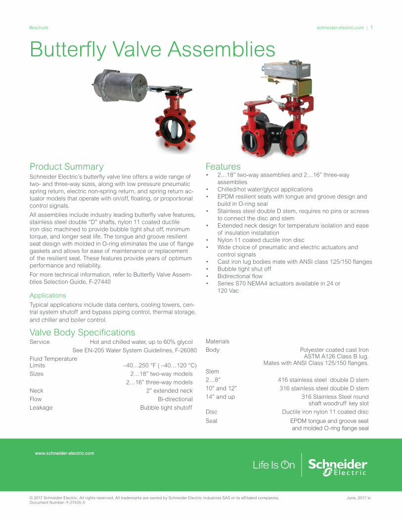
Product SummarySchneider Electric’s butterfly valve line offers a wide range of two- and three-way sizes, along with low pressure pneumatic spring return, electric non-spring return, and spring return ac-tuator models that operate with on/off, floating, or proportional control signals.
All assemblies include industry leading butterfly valve features, stainless steel double “D” shafts, nylon 11 coated ductile iron disc machined to provide bubble tight shut off, minimum torque, and longer seat life. The tongue and groove resilient seat design with molded in O-ring eliminates the use of flange gaskets and allows for ease of maintenance or replacement of the resilient seat. These features provide years of optimum performance and reliability.
For more technical information, refer to Butterfly Valve Assem-blies Selection Guide, F-27440
ApplicationsTypical applications include data centers, cooling towers, cen-tral system shutoff and bypass piping control, thermal storage, and chiller and boiler control.
Materials
Body Polyester coated cast Iron ASTM A126 Class B lug. Mates with ANSI Class 125/150 flanges.
Stem
2…8” 416 stainless steel double D stem
10” and 12” 316 stainless steel double D stem
14” and up 316 Stainless Steel round shaft woodruff key slot
Disc Ductile iron nylon 11 coated disc
Seat EPDM tongue and groove seat and molded O-ring flange seal
2 | schneider-electric.com Brochure
June, 2017 tc © 2017 Schneider Electric. All rights reserved. All trademarks are owned by Schneider Electric Industries SAS or its affiliated companies. Document Number: F-27435-5
Butterfly Valve Numbering SystemRubber Lined
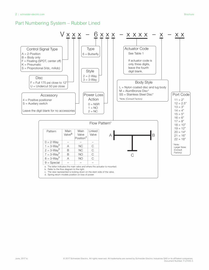
V x xx – 6 x xx – x x xx – x – xx
Flow Patternc
Control Signal TypeA = 2-PositionB = Body onlyF = Floating (SPDT, center off)K = PneumaticS = Proprotional (Vdc, mAdc)
DiscF = Full 175 psi close to 12"U = Undercut 50 psi close
Accessory4 = Positive positionerS = Auxilary switch
Leave the digit blank for no accessories
Type6 = Butterfly
Style2 = 2-Way3 = 3-Way
Power LossAction0 = NSR1 = NO2 = NC
0 = 2-Way – – –1 = 3-Wayb A NC C2 = 3-Wayb B NC C7 = 3-Wayb B NO C8 = 3-Wayb A NO C9 = Special – – –a. The letter indicates the main valve and where the actuator is mounted.b. Refer to the flow diagram to the right. c. The view represented is looking down on the stem side of the valve.d. Spring return models position on loss of power
Actuator CodeSee Table 1
If actuator code isonly three digits, leave the fourth digit blank.
Body StyleL = Nylon coated disc and lug bodyM = AlumBronze Disc* SS = Stainless Steel Disc**Note: (Consult Factory)
Port Code11 = 2”12 = 2.5”13 = 3”14 = 4”15 = 5”16 = 6”17 = 8”18 = 10”19 = 12”20 = 14“21 = 16”22 = 18”
MainValve
Positiond
MainValvea
Pattern LinkedValve
* Note: Larger Sizes (Consult Factory)
A B
C
Part Numbering System – Rubber Lined
schneider-electric.com | 3Brochure
© 2017 Schneider Electric. All rights reserved. All trademarks are owned by Schneider Electric Industries SAS or its affiliated companies. June, 2017 tcDocument Number: F-27435-5
Actuator Codes
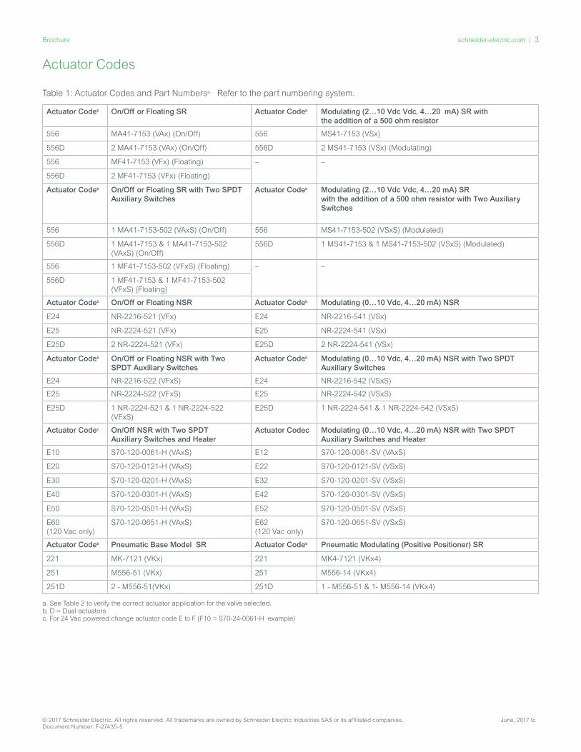
Table 1: Actuator Codes and Part Numbersa . Refer to the part numbering system.
Actuator Codeb On/Off or Floating SR Actuator Codeb Modulating (2…10 Vdc Vdc, 4…20 mA) SR with the addition of a 500 ohm resistor
556 MA41-7153 (VAx) (On/Off) 556 MS41-7153 (VSx)
556D 2 MA41-7153 (VAx) (On/Off) 556D 2 MS41-7153 (VSx) (Modulating)
556 MF41-7153 (VFx) (Floating) – –
556D 2 MF41-7153 (VFx) (Floating)
Actuator Codeb On/Off or Floating SR with Two SPDT Auxiliary Switches
Actuator Codeb Modulating (2…10 Vdc Vdc, 4…20 mA) SR with the addition of a 500 ohm resistor with Two Auxiliary Switches
556 1 MA41-7153-502 (VAxS) (On/Off) 556 MS41-7153-502 (VSxS) (Modulated)
556D 1 MA41-7153 & 1 MA41-7153-502 (VAxS) (On/Off)
556D 1 MS41-7153 & 1 MS41-7153-502 (VSxS) (Modulated)
556 1 MF41-7153-502 (VFxS) (Floating) – –
556D 1 MF41-7153 & 1 MF41-7153-502 (VFxS) (Floating)
Actuator Codeb On/Off or Floating NSR Actuator Codeb Modulating (0…10 Vdc, 4…20 mA) NSR
E24 NR-2216-521 (VFx) E24 NR-2216-541 (VSx)
E25 NR-2224-521 (VFx) E25 NR-2224-541 (VSx)
E25D 2 NR-2224-521 (VFx) E25D 2 NR-2224-541 (VSx)
Actuator Codeb On/Off or Floating NSR with Two SPDT Auxiliary Switches
Actuator Codeb Modulating (0…10 Vdc, 4…20 mA) NSR with Two SPDT Auxiliary Switches
E24 NR-2216-522 (VFxS) E24 NR-2216-542 (VSxS)
E25 NR-2224-522 (VFxS) E25 NR-2224-542 (VSxS)
E25D 1 NR-2224-521 & 1 NR-2224-522 (VFxS)
E25D 1 NR-2224-541 & 1 NR-2224-542 (VSxS)
Actuator Codec On/Off NSR with Two SPDT Auxiliary Switches and Heater
Actuator Codec Modulating (0…10 Vdc, 4…20 mA) NSR with Two SPDT Auxiliary Switches and Heater
E10 S70-120-0061-H (VAxS) E12 S70-120-0061-SV (VAxS)
E20 S70-120-0121-H (VAxS) E22 S70-120-0121-SV (VSxS)
E30 S70-120-0201-H (VAxS) E32 S70-120-0201-SV (VSxS)
E40 S70-120-0301-H (VAxS) E42 S70-120-0301-SV (VSxS)
E50 S70-120-0501-H (VAxS) E52 S70-120-0501-SV (VSxS)
E60 (120 Vac only)
S70-120-0651-H (VAxS) E62 (120 Vac only)
S70-120-0651-SV (VSxS)
Actuator Codeb Pneumatic Base Model SR Actuator Codeb Pneumatic Modulating (Positive Positioner) SR
221 MK-7121 (VKx) 221 MK4-7121 (VKx4)
251 M556-51 (VKx) 251 M556-14 (VKx4)
251D 2 - M556-51(VKx) 251D 1 - M556-51 & 1- M556-14 (VKx4)
a. See Table 2 to verify the correct actuator application for the valve selected.b. D = Dual actuatorsc. For 24 Vac powered change actuator code E to F (F10 = S70-24-0061-H example)
4 | schneider-electric.com Brochure
June, 2017 tc © 2017 Schneider Electric. All rights reserved. All trademarks are owned by Schneider Electric Industries SAS or its affiliated companies. Document Number: F-27435-5
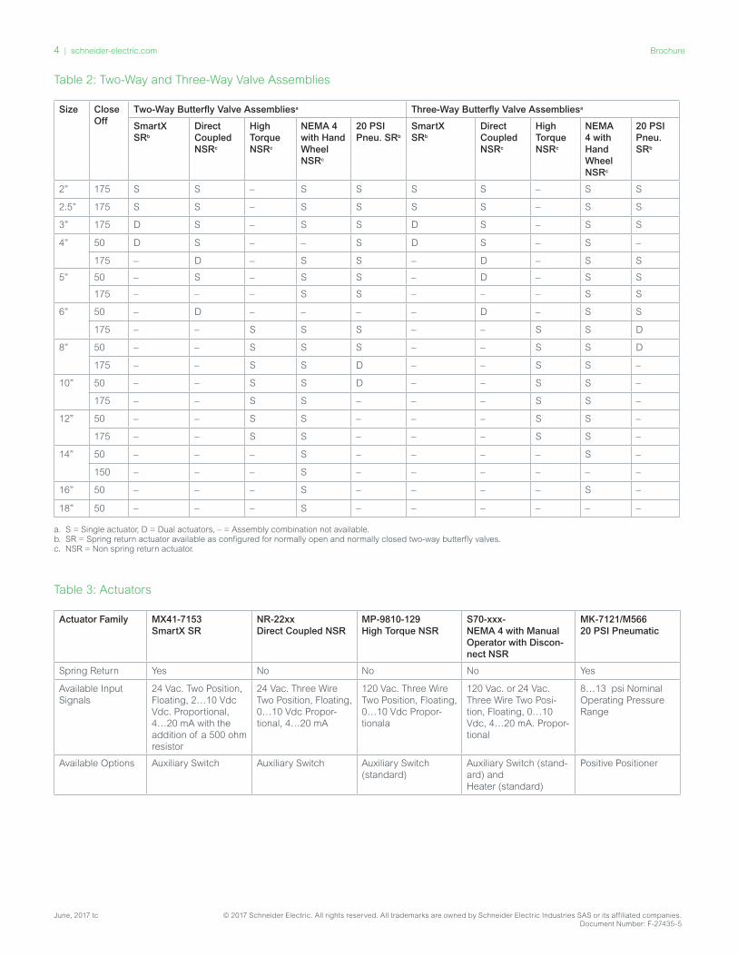
Table 2: Two-Way and Three-Way Valve Assemblies
Size Close Off
Two-Way Butterfly Valve Assembliesa Three-Way Butterfly Valve Assembliesa
SmartX SRb
Direct Coupled NSRc
High Torque NSRc
NEMA 4 with Hand Wheel NSRc
20 PSI Pneu. SRb
SmartX SRb
Direct Coupled NSRc
High Torque NSRc
NEMA 4 with Hand Wheel NSRc
20 PSI Pneu. SRb
2” 175 S S – S S S S – S S
2.5” 175 S S – S S S S – S S
3” 175 D S – S S D S – S S
4” 50 D S – – S D S – S –
175 – D – S S – D – S S
5” 50 – S – S S – D – S S
175 – – – S S – – – S S
6” 50 – D – – – – D – S S
175 – – S S S – – S S D
8” 50 – – S S S – – S S D
175 – – S S D – – S S –
10” 50 – – S S D – – S S –
175 – – S S – – – S S –
12” 50 – – S S – – – S S –
175 – – S S – – – S S –
14” 50 – – – S – – – – S –
150 – – – S – – – – – –
16” 50 – – – S – – – – S –
18” 50 – – – S – – – – – –
a. S = Single actuator, D = Dual actuators, – = Assembly combination not available.b. SR = Spring return actuator available as configured for normally open and normally closed two-way butterfly valves.c. NSR = Non spring return actuator.
Table 3: Actuators
Actuator Family MX41-7153 SmartX SR
NR-22xx Direct Coupled NSR
MP-9810-129 High Torque NSR
S70-xxx- NEMA 4 with Manual Operator with Discon-nect NSR
MK-7121/M566 20 PSI Pneumatic
Spring Return Yes No No No Yes
Available Input Signals
24 Vac. Two Position, Floating, 2…10 Vdc Vdc. Proportional, 4…20 mA with the addition of a 500 ohm resistor
24 Vac. Three Wire Two Position, Floating, 0…10 Vdc Propor-tional, 4…20 mA
120 Vac. Three Wire Two Position, Floating, 0…10 Vdc Propor-tionala
120 Vac. or 24 Vac. Three Wire Two Posi-tion, Floating, 0…10 Vdc, 4…20 mA. Propor-tional
8…13 psi Nominal Operating Pressure Range
Available Options Auxiliary Switch Auxiliary Switch Auxiliary Switch (standard)
Auxiliary Switch (stand-ard) and Heater (standard)
Positive Positioner
schneider-electric.com | 5Brochure
© 2017 Schneider Electric. All rights reserved. All trademarks are owned by Schneider Electric Industries SAS or its affiliated companies. June, 2017 tcDocument Number: F-27435-5
6 | schneider-electric.com Brochure
June, 2017 tc © 2017 Schneider Electric. All rights reserved. All trademarks are owned by Schneider Electric Industries SAS or its affiliated companies. Document Number: F-27435-5

schneider-electric.com | 7Brochure
© 2017 Schneider Electric. All rights reserved. All trademarks are owned by Schneider Electric Industries SAS or its affiliated companies. June, 2017 tcDocument Number: F-27435-5
schneider-electric.com | 8Brochure
© 2017 Schneider Electric. All rights reserved. All trademarks are owned by Schneider Electric Industries SAS or its affiliated companies. June, 2017 tcDocument Number: F-27435-5
IMAGE OR IMAGES
IMAGE OR IMAGES