PRODUCT SPECIFICATIONS - LennoxPROs.com · Med/High 2178 2173 2173 2158 2138 2098 2038 1963 1883...
12
Gas Furnaces 80AF 80% AFUE 44,000 to 132,000 Btuh Input 1.5 to 5 Tons Add-On Cooling INSTALLATION OPTIONS • Available in Upflow/Horizontal and Counterflow models HEAT EXCHANGER • Aluminized steel tapered design primary heat exchanger with crimped construction for long life BURNERS • Aluminized steel inshot burners for smooth combustion CABINET CONSTRUCTION • Unitized construction for cabinet integrity • Bottom or side return air • Baked on pre-painted steel cabinet finish • Left or right side gas and electric entry • Less than 2% air leakage (meets ANSI/ASHRAE Standard 193-2010) BLOWER • Easily removable slide-out blower design • PSC multi-speed permanently lubricated blower motor for low maintenance and optimum efficiency CONTROLS • Single stage gas valve • Integrated ignition and fan control board features self diagnostics • Hot surface ignitor VENTING • Permanently lubricated draft motor is air cooled for long life • “L” designated units comply with California’s South Coast Air Quality Management District Low NOx requirements Warranty Heat Exchanger - 20 Year Limited Parts - 5 Year Limited PRODUCT SPECIFICATIONS Upflow / Horizontal Counterflow
Transcript of PRODUCT SPECIFICATIONS - LennoxPROs.com · Med/High 2178 2173 2173 2158 2138 2098 2038 1963 1883...

Gas Furnaces80AF
80% AFUE44,000 to 132,000 Btuh Input
1.5 to 5 Tons Add-On Cooling
INSTALLATION OPTIONS
• Available in Upflow/Horizontal and Counterflow models
HEAT EXCHANGER
• Aluminized steel tapered design primary heat exchanger with crimped construction for long life
BURNERS
• Aluminized steel inshot burners for smooth combustion
CABINET CONSTRUCTION
• Unitized construction for cabinet integrity
• Bottom or side return air
• Baked on pre-painted steel cabinet finish
• Left or right side gas and electric entry
• Less than 2% air leakage (meets ANSI/ASHRAE Standard 193-2010)
BLOWER
• Easily removable slide-out blower design
• PSC multi-speed permanently lubricated blower motor for low maintenance and optimum efficiency
CONTROLS
• Single stage gas valve
• Integrated ignition and fan control board features self diagnostics
• Hot surface ignitor
VENTING
• Permanently lubricated draft motor is air cooled for long life
• “L” designated units comply with California’s South Coast Air Quality Management District Low NOx requirements
Warranty Heat Exchanger - 20 Year Limited
Parts - 5 Year Limited
PRODUCT SPECIFICATIONS
Upflow /Horizontal
Counterflow

Gas Furnaces80AFModel Number Identification
80 AF 1 UH 110 P 20 C L
UH = Upflow / HorizontalDF = Counterflow
P = PSC Direct Drive Blower Motor
Nominal Airflow08 = 800 cfm12 = 1200 cfm16 = 1600 cfm20 = 2000 cfm
80 = AFUE
AF = Aire-Flo
Heat Input045 = 45,000 Btuh070 = 70,000 Btuh090 = 90,000 Btuh
110 = 110,000 Btuh135 = 135,000 Btuh
SpecificationsModel No.
Model No. - Low Nox80AF1UH045P12A
80AF1UH045P12AL80AF1UH070P12A
80AF1UH070P12AL80AF1UH090P12B
- - -80AF1UH090P16B80AF1UH090P16BL
80AF1UH110P16C- - -
80AF1UH110P20C80AF1UH110P20CL
Upflow / Horiz. Upflow / Horiz. Upflow / Horiz. Upflow / Horiz. Upflow / Horiz. Upflow / Horiz.Input Btuh 44,000 66,000 88,000 88,000 110,000 110,000Output Btuh 35,000 54,000 71,000 71,000 89,000 89,000AFUE (Isolated Comb. System) 80% 80% 80% 80% 80% 80%Temperature Rise (°F) 15 - 45 30 - 60 25 - 55 25 - 55 25 - 55 30 - 60Gas Pipe Size (in.) 1/2 1/2 1/2 1/2 1/2 1/2Flue Connection in. (diameter) 4 4 4 4 4 4Volts/Hertz/Phase 120/60/1 120/60/1 120/60/1 120/60/1 120/60/1 120/60/1Blower Motor Horsepower 1/3 1/3 1/3 1/2 1/2 3/4Add-On Cooling (tons) 2-3 2-3 2-3 3-4 3-4 4-5Circuit Breaker or Fuse 15 15 15 15 15 15Full Load Amps 3.1 3.1 6.1 8.2 8.2 10Blower Wheel Size (Dia. x Width) 10 x 8 10 x 8 10 x 9 10 x 10 10 x 10 11½ x 10Shipping Weight (lbs.) 105 114 131 183 151 161
1 = 1-Stage
Cabinet WidthA = 14-1/2 in.B = 17-1/2 in.C = 21 inD = 24-1/2 in.
SpecificationsModel No.
80AF1UH135P20D 80AF1DF045P12A 80AF1DF070P12A 80AF1DF090P16B 80AF1DF110P20C
Upflow / Horiz. Counterflow Counterflow Counterflow CounterflowInput Btuh 132,000 44,000 66,000 88,000 110,000Output Btuh 107,000 35,000 54,000 71,000 89,000AFUE (Isolated Comb. System) 80% 80% 80% 80% 80%Temperature Rise (°F) 30 - 60 15 - 45 25 - 55 25 - 55 30 - 60Gas Pipe Size (in.) 1/2 1/2 1/2 1/2 1/2Flue Connection in. (diameter) 4 4 4 4 4Volts/Hertz/Phase 120/60/1 120/60/1 120/60/1 120/60/1 120/60/1Blower Motor Horsepower 3/4 1/3 1/3 1/2 3/4Add-On Cooling (tons) 4-5 2-3 2-3 3-4 4-5Circuit Breaker or Fuse 15 15 15 15 15Full Load Amps 11.5 6.1 6.1 8.2 10.0Blower Wheel Size (Dia. x Width) 11 x 11 10 x 8 10 x 8 10 x 10 11½ x 10Shipping Weight (lbs.) 174 112 121 140 163
L = Low NOx

Gas Furnaces80AF
Accessories - Upflow / HorizontalModel No.
80AF1UH045P12A80AF1UH070P12A
80AF1UH090P12B80AF1UH090P16B
80AF1UH110P16C80AF1UH110P20C
80AF1UH135P20D
Upflow / Horizontal Upflow / Horizontal Upflow / Horizontal Upflow / HorizontalCABINETHorizontal Suspension Kit (Horizontal) 51W10 51W10 51W10 51W10Return Air Base (Upflow) 68W61 68W62 68W63 68W64FILTER KITS1 Air Filter and
Rack Kit (Up-flow/Horizontal
Horizontal (end) 87L95 (14 x 25 x 1) 87L96 (18 x 25 x 1) 87L97 (20 x 25 x 1) 87L98 (25 x 25 x 1) Side Return(Upflow)
Single 44J22 44J22 44J22 44J2210-pack 66K63 66K63 66K63 66K63
Size 16 x 25 x 1 16 x 25 x 1 16 x 25 x 1 16 x 25 x 1GAS HEATINGHigh Altitude Pressure Switch Kit
0-4500 ft. No Change No Change No Change No Change 4501-7500 ft. 80W52 (045, 070) 80W52 (090) 80W57 (110) 80W57 (135)
7501-10,000 ft. 80W51 (045, 070) 80W51 (090) 80W52 (110) 80W51 (135)Natural to LP Conversion Kit 0-7500 ft. 11K49 11K49 11K49 11K49
7501-10,000 ft. 11K44 11K44 11K44 11K44LP to Natural Conversion Kit 0-7500 ft. 73W81 73W81 73W81 73W81Natural Gas High Altitude Orifice Kit 7501-10,000 ft. 73W37 73W37 73W37 73W37NIGHT SERVICE KITNight Service Kit 68W80 68W80 68W80 68W80VENTINGVent Adaptor − 6 in. conn. size upflow applications only 18M79 18M79 18M79 18M791 Cleanable polyurethane frame type filter.
Accessories - CounterflowModel No.
80AF1DF045P12A80AF1DF070P12A 80AF1DF090P16B 80AF1DF110P20C
Counterflow Counterflow CounterflowCABINETCombustible Flooring Base (Counterflow) 11M59 11M60 11M61FILTER KITS1 Air Filter and Rack Kit (Counterflow) 51W06 ((1) 20 x 16 x 1 51W07 (2) 20 x 20 x 1 51W08 (2) 20 x 20 x 1GAS HEATINGHigh Altitude Pressure Switch Kit
4501-7500 ft. 80W52 (045, 070) 80W52 (090) 80W57 (110)7501-10,000 ft. 80W51 (045, 070) 80W51 (090) 80W52 (110)
Natural to LP Conversion Kit 0-7500 ft. 11K49 11K49 11K497501-10,000 ft. 11K44 11K44 11K44
LP to Natural Conversion Kit 0-7500 ft. 73W81 73W81 73W81LP High Altitude Orifice Kit 7501-10,000 ft. 73W37 73W37 73W37NIGHT SERVICE KITNight Service Kit 68W80 68W80 68W801 Cleanable polyurethane frame type filter.

Gas Furnaces80AF
Blower DataModel No. Blower
Speed
1 CFM @ External Static Pressure - in w.c. Less Filter.00 .10 .20 .30 .40 .50 .60 .70 .80 .90
80AF1UH045P12A(Upflow / Horizontal)
High 1663 1613 1563 1518 1463 1393 1323 1218 1128 1013Med/High 1328 1328 1323 1308 1268 1228 1178 1128 1003 923Med/Low 1133 1123 1108 1133 1118 1078 1043 988 918 813
Low 918 933 943 943 938 918 878 833 778 643
80AF1UH070P12A(Upflow / Horizontal)
High 1653 1613 1573 1513 1473 1393 1333 1238 1153 1038Med/High 1363 1358 1348 1328 1293 1263 1198 1118 1038 933Med/Low 1088 1108 1128 1123 1093 1073 1028 968 908 823
Low 928 938 953 948 938 918 873 828 768 778
80AF1UH090P12B(Upflow / Horizontal)
High 1788 1753 1718 1678 1623 1528 1463 1358 1248 1153Med/High 1443 1428 1413 1403 1363 1308 1268 1178 1098 993Med/Low 1188 1178 1163 1163 1143 1118 1078 1013 928 808
Low 963 963 968 973 948 918 903 833 778 673
80AF1UH090P16B(Upflow / Horizontal)
High 2153 2023 1903 1833 1763 1658 1578 1463 1348 1193Med/High 1818 1773 1733 1698 1628 1553 1463 1358 1223 1113Med/Low 1508 1518 1528 1493 1453 1403 1323 1253 1148 1013
Low 1253 1273 1298 1298 1273 1218 1183 1108 1013 913
80AF1UH110P16C(Upflow / Horizontal)
High 2163 2118 2073 2008 1933 1843 1768 1673 1553 1418Med/High 1838 1813 1783 1738 1688 1628 1568 1463 1343 1183Med/Low 1558 1548 1533 1538 1498 1463 1388 1313 1198 1053
Low 1263 1293 1328 1328 1313 1288 1228 1163 1043 90380AF1UH110P20C
(Upflow / Horizontal)Single Side Return Air - Air
volumes in bold require field fabricated transition to accommodate 20 x 25 x 1 in. air filter in order to maintain
proper air velocity.
High 2708 2598 2498 2428 2343 2253 2168 2078 1958 1823
Med/High 2168 2153 2143 2108 2063 2003 1948 1843 1778 1693
Med/Low 1688 1733 1778 1788 1798 1778 1748 1703 1633 1548
Low 1403 1423 1443 1478 1473 1473 1483 1453 1418 1348
Bottom Return Air, Side Return Air with Optional Return Air Base, Return Air from Both
Sides or Return Air from Bot-tom and One Side.
High 2568 2513 2458 2378 2288 2193 2123 2008 1898 1788
Med/High 2263 2243 2223 2173 2098 2048 1978 1883 1803 1703
Med/Low 1838 1853 1863 1878 1858 1838 1788 1713 1668 1538
Low 1423 1448 1473 1533 1563 1563 1543 1498 1463 1368
80AF1UH135P20D(Upflow / Horizontal)
Single Side Return Air - Air volumes in bold require
field fabricated transition to accommodate 20 x 25 x 1 in. air filter in order to maintain
proper air velocity.
High 2803 2718 2633 2568 2488 2398 2298 2208 2103 1978
Med/High 2178 2173 2173 2158 2138 2098 2038 1963 1883 1783
Med/Low 1698 1708 1713 1783 1768 1773 1768 1733 1668 1593
Low 1253 1313 1373 1413 1443 1463 1473 1448 1423 1373
Bottom Return Air, Side Return Air with Optional Return Air Base, Return Air from Both
Sides or Return Air from Bot-tom and One Side.
High 2778 2743 2713 2598 2488 2413 2328 2213 2113 1978
Med/High 2198 2213 2228 2213 2178 2128 2073 1988 1883 1783
Med/Low 1658 1718 1778 1813 1838 1818 1818 1753 1673 1598
Low 1338 1388 1438 1453 1478 1498 1488 1468 1428 1383
Notes:1 Maximum approved external static pressure is 0.50 in. w.c.

Gas Furnaces80AF
Blower DataModel No. Blower
Speed
1 CFM @ External Static Pressure - in w.c. Less Filter.00 .10 .20 .30 .40 .50 .60 .70 .80 .90
80AF1DF045P12A(Counterflow)
High 1613 1518 1458 1408 1338 1248 1198 1133 1023 918Med/High 1478 1378 1343 1288 1228 1183 1098 1053 953 843Med/Low 1228 1138 1123 1103 1078 1033 993 938 863 758
Low 1033 938 938 943 938 888 863 808 733 648
80AF1DF070P12A(Counterflow)
High 1673 1553 1498 1453 1383 1298 1208 1133 1033 918Med/High 1488 1378 1348 1308 1258 1193 1123 1058 968 858Med/Low 1263 1153 1143 1113 1073 1043 978 893 828 718
Low 1043 948 948 933 908 898 843 793 708 623
80AF1DF090P16B(Counterflow)
High 2083 1923 1858 1773 1688 1588 1478 1333 1213 1058Med/High 1948 1788 1738 1668 1593 1493 1408 1268 1133 998Med/Low 1733 1578 1538 1488 1438 1358 1253 1143 1013 898
Low 1468 1323 1313 1288 1258 1203 1143 1033 908 803
80AF1DF110P20C(Counterflow)
High 2858 2753 2663 2548 2528 2378 2268 2188 2108 1983Med/High 2428 2318 2313 2248 2213 2143 2058 2013 1943 1818Med/Low 1998 1883 1928 1938 1928 1913 1878 1813 1743 1658
Low 1598 1523 1558 1598 1613 1618 1608 1568 1508 1468Notes:1 Maximum approved external static pressure is 0.50 in. w.c.
Clearance to Combustibles (in.)UPFLOW / COUNTERFLOW POSITION
Vent Type Type B1 Type C
Sides 0 1 0
Rear 0 0Top 1 1Front 2-1/4 2-1/4Front (service/alcove) 24 24Floor Combustible CombustibleFlue 1 (25) 6 (152)NOTE − Air for combustion must conform to the methods outlined in the Na-
tional Fuel Gas Code (NFPA 54/ANSI-Z223.1).NOTE − In the U.S. flue sizing must conform to the methods outlined in the
current National Fuel Gas Code (NFPA 54/ANSI-Z223.1) or applicable provisions of local building codes.
1 Left side requires 4 in. if single wall vent is used on 14-1/2 in. cabinets, 2 in. on 17-1/2 in. cabinets.
HORIZONTAL POSITIONVent Type Type B1 Type C
End 1 2 1 2
Rear 0 0Top 1 0 1 0Front 2-1/4 2-1/4Front (service) 24 24Floor Combustible CombustibleFlue 1 6NOTE − Air for combustion must conform to the methods outlined in the Na-
tional Fuel Gas Code (NFPA 54/ANSI-Z223.1).NOTE − In the U.S. flue sizing must conform to the methods outlined in the
current National Fuel Gas Code (NFPA 54/ANSI-Z223.1) or applicable provisions of local building codes.
1 Line contact installation permissible between jacket top or sides and building joists.
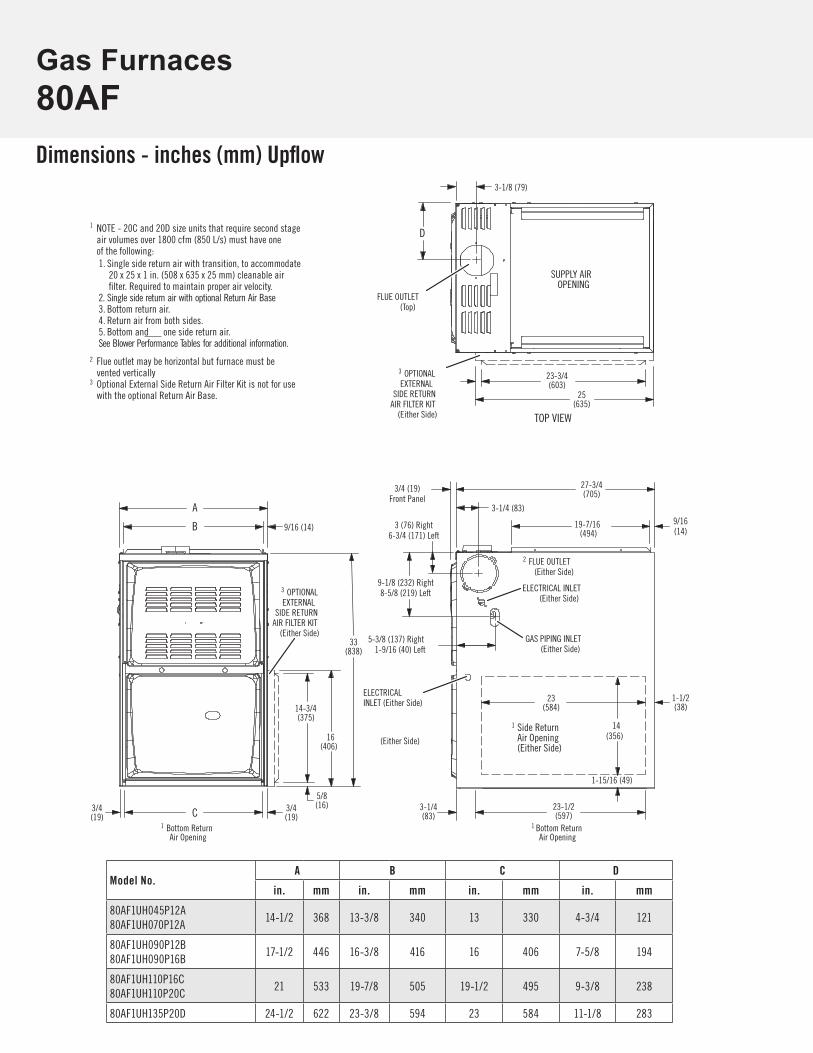
Gas Furnaces80AFDimensions - inches (mm) Upflow
Model No.A B C D
in. mm in. mm in. mm in. mm
80AF1UH045P12A80AF1UH070P12A
14-1/2 368 13-3/8 340 13 330 4-3/4 121
80AF1UH090P12B80AF1UH090P16B
17-1/2 446 16-3/8 416 16 406 7-5/8 194
80AF1UH110P16C80AF1UH110P20C
21 533 19-7/8 505 19-1/2 495 9-3/8 238
80AF1UH135P20D 24-1/2 622 23-3/8 594 23 584 11-1/8 283
23(584)
(19)3/4
(19)1 Bottom Return
Air Opening
GAS PIPING INLET(Either Side)
Side ReturnAir Opening(Either Side)
1 Bottom Return
Air Opening
FLUE OUTLET(Top)
ELECTRICAL INLET(Either Side)
SUPPLY AIROPENING
TOP VIEW
A
B 9/16 (14)
C
D
3/4
27-3/4(705)
19-7/16(494)
23-1/2(597)
1-1/2(38)
9-1/8 (232) Right8-5/8 (219) Left
5-3/8 (137) Right1-9/16 (40) Left
33(838)
3-1/8 (79)
1-15/16 (49)
14(356)
9/16(14)
3 (76) Right6-3/4 (171) Left
2
FLUE OUTLET(Either Side)
3 OPTIONALEXTERNAL
SIDE RETURNAIR FILTER KIT
(Either Side)
16(406)
14-3/4(375)
3 OPTIONALEXTERNAL
SIDE RETURNAIR FILTER KIT
(Either Side)
2 Flue outlet may be horizontal but furnace must bevented vertically
3 Optional External Side Return Air Filter Kit is not for usewith the optional Return Air Base.
1 NOTE - 20C and 20D size units that require second stageair volumes over 1800 cfm (850 L/s) must have oneof the following:1. Single side return air with transition, to accommodate
20 x 25 x 1 in. (508 x 635 x 25 mm) cleanable airfilter. Required to maintain proper air velocity.
2. Single side return air with optional Return Air Base3. Bottom return air.4. Return air from both sides.5. Bottom and one side return air.See Blower Performance Tables for additional information.
3-1/4 (83)
5/8(16)
1
3-1/4(83)
23-3/4(603)
25(635)
3/4 (19)Front Panel
ELECTRICALINLET (Either Side)
(Either Side)

Gas Furnaces80AF
27-3/4(705)
27-3/4(705)
D
A
TOP VIEW
33(838)
27-3/4(705)
A
(79)
6-3/4
GAS PIPING INLET(Top or Bottom)
RETURNAIR
OPENING
FLUE OUTLET(Top)
ELECTRICAL INLET(Top or Bottom)
SUPPLYAIR
OPENING
FRONT VIEW
TOP VIEW
CA
END VIEWEND VIEW
33(838)
27-3/4(705)
19-7/16(494)
9/16(14)
B
23-1/2(597)
4-1/4(108)
(19)
5-3/8 (137) Top1-9/16 (40) Bottom
9-1/8 (232) Top8-5/8 (219) Bottom
3 (76)
(171)
3-1/8
1 FLUEOUTLET
(End)
LEFT-HAND AIR DISCHARGE1 Flue outlet may be from end but
furnace must be vented vertically
FRONT VIEWEND VIEW END VIEW
1 FLUE OUTLET(Top)
3 (76)
6-3/4(171)
AIRFLOW
GAS PIPING INLET(Top or Bottom)
ELECTRICAL INLET(Top or Bottom)
RIGHT-HAND AIR DISCHARGE
1 Flue outlet may be horizontal butfurnace must be vented vertically
9-1/8 (232) Bottom8 (203) Top5-3/8 (137) Bottom
1-5/8 (41) Top
9/16(14)
3/4
AIRFLOW
AIRFLOW
19-7/16(494)
9/16(14)B
9/16(14)
D
A
1 FLUEOUTLET
(End) (79)3-1/8
SUPPLYAIR
OPENING
RETURNAIR
OPENING
C
23-1/2(597)
4-1/4(108)
(19)3/4
AIRFLOW
11/16 (17)Front Panel
3/4 (19)Front Panel
3/4(19)
(19)3/4
3/4(19)
3/4(19)
Dimensions - inches (mm) Horizontal
Model No.A B C D
in. mm in. mm in. mm in. mm
80AF1UH045P12A80AF1UH070P12A
14-1/2 368 13-3/8 340 13 330 4-3/4 121
80AF1UH090P12B80AF1UH090P16B
17-1/2 446 16-3/8 416 16 406 7-5/8 194
80AF1UH110P16C80AF1UH110P20C
21 533 19-7/8 505 19-1/2 495 9-3/8 238
80AF1UH135P20D 24-1/2 622 23-3/8 594 23 584 11-1/8 283
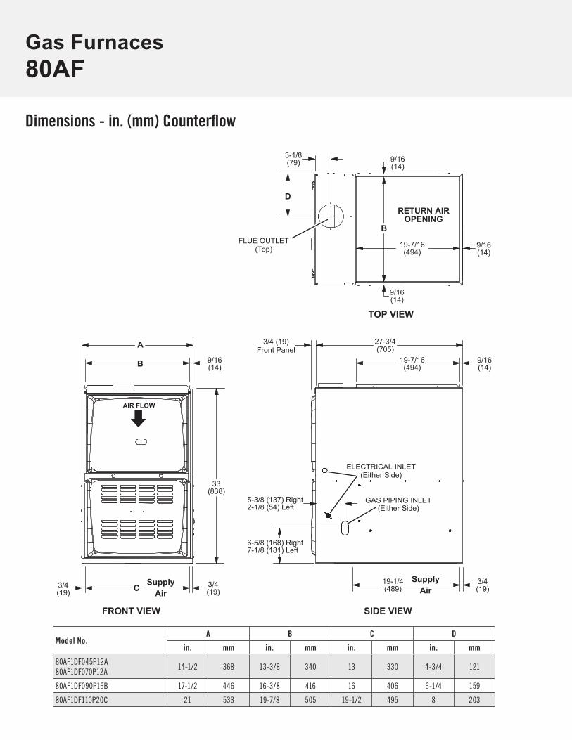
80AFGas Furnaces
Dimensions - in. (mm) Counterflow
Model No.A B C D
in. mm in. mm in. mm in. mm
80AF1DF045P12A80AF1DF070P12A
14-1/2 368 13-3/8 340 13 330 4-3/4 121
80AF1DF090P16B 17-1/2 446 16-3/8 416 16 406 6-1/4 159
80AF1DF110P20C 21 533 19-7/8 505 19-1/2 495 8 203
3/4 (19)Front Panel
GAS PIPING INLET(Either Side)
FLUE OUTLET(Top)
ELECTRICAL INLET(Either Side)
RETURN AIROPENING
FRONT VIEW SIDE VIEW
TOP VIEW
A
B
C
D
3/4(19)
27-3/4(705)
19-1/4(489)
6-5/8 (168) Right7-1/8 (181) Left
5-3/8 (137) Right2-1/8 (54) Left
33(838)
AIR FLOW
3/4(19)
19-7/16(494)
9/16(14)
B
SupplyAir
SupplyAir
9/16(14)
9/16(14)
3-1/8(79)
9/16(14)
9/16(14)
19-7/16(494)
3/4(19)


Gas Furnaces80AF
RevisionsSections Description of Change
Product Specifications Temperature Rise Ranges updated.
1.800.982.2333 www.aireflo-hvac.com 210599 (11/2016) © Aire-Flo Heating and Cooling, 2016