PRODUCT OVERVIEW MBR - Mak Water Product... · 2017-12-04 · Overview MAK Water’s Membrane...
41
PRODUCT OVERVIEW MBR
Transcript of PRODUCT OVERVIEW MBR - Mak Water Product... · 2017-12-04 · Overview MAK Water’s Membrane...

PRODUCT
OVERVIEW
MBR
OverviewMAK Water’s Membrane Bioreactor (MBR) waste water
treatment plants are designed to treat domestic strength
sewage, to achieve Class A+ treated effluent, suitable for reuse
in virtually all non-potable “risk category high” applications.
MAK Water’s MBR plants are containerised systems for easy
deployment to remote locations.
The MAK Advantage:
• High quality Australian designed and built systems
• Proven design, approved by Department of Health (WA)
• Containerised system minimises site installation work
• Factory tested prior to delivery
• Nationwide service & maintenance capabilities
• Remote monitoring for expert process support
• Fully automated systems minimise operator attendance
• MAK standard designs for fast lead times
• Optimised designs to suit client’s objectives
• Fully customisable to accommodate client specific
engineering standards, vendor data requirements and site
preferred electrical equipment
• Extensive hire fleet available for rapid deployment
MAK Containerised 200 m3/day MBR Plant
MAK Containerised 2 x 250 m3/day MBR Plant

Overview
The MBR process is a suspended growth activated sludge system that utilises microporous membranes
for solid/liquid separation in lieu of secondary clarifiers.
The standard treatment process involves influent screening, biological degradation (anoxic/aerobic
treatment), cross flow ultrafiltration (UF) pressure membranes (external to the bioreactor), with
automated chemical cleaning system, and effluent sterilization (chlorination).
Additional treatment steps for enhanced nutrient removal (T-N & T-P), secondary effluent sterilization
(UV or residual trim hypo dosing), and sludge de-watering systems may be added as required to suit
influent quality and/or treated effluent quality requirements.
The pretested, compact nature of the containerised design minimises site installation works and enables
plug and play operation.

OverviewThe following table summarises typical influent and treated effluent values.
NOTES:
• MAK Water recommends an influent analysis be carried out prior to detailed design, if possible
• ENR = Enhanced Nutrient Removal (optional)
Parameter Unit Influent Effluent (Class A+)
BOD mg/L 150~500 <10
TSS mg/L 150~400 <10
T-N mg/L <50 (<80 with ENR) <40 (<10 with ENR)
T-P mg/L <15 <10 (<3 with ENR)
Turbidity NTU - <2
E.Coli CFU/100 mL - <1
Coliphages PFU/100 mL - <1
Clostridia CFU/100 mL - <1
Free Chlorine mg/L - 0.2~2

Process Steps
Balance
Tank(s)
Raw
sewage
Balance Tank
The Balance Tank is designed to handle peak flows and allow a pre-determined and controlled flow for
subsequent treatment. The waste water is temporarily stored in the Balance Tank before being pumped
to the inlet (micron) screen located above the MBR’s bioreactor. The feed pump flow rate is set using a
flow control valve; excess flow is returned to the balance tank to maintain homogeneity of influent feed.
The Balance Tank level is regulated by 3 float-type level switches.
The feed pump flow rate is continuously monitored; an alarm is generated by any abnormal readings.

Process Steps
Balance
Tank(s)
Raw
sewage
Micro Screening
The raw sewage is pumped from the balance tank to the inlet (micron) screen. The micro screen is a
disc filter comprising a 250 micron filtering mesh with a self-cleaning system using pressurised water (or
treated effluent); it is ideally suited for MBR pre-screening applications, thanks to the ability to trap hairs
and fibres, which, if not removed, have the potential to foul the UF membranes downstream.
Particles are retained in the mesh; when the pre-set pressure differential is reached, the washing cycle
begins. While the discs slowly turn, water jets send water towards the mesh, dragging the solids to a
hopper situated in the centre part of the equipment.
Screenings are deposited into a waste receptacle; screened effluent discharges into the bioreactor’s
anoxic tank for treatment.
Micro
Screen
Waste
Bin
Potable Water or
Treated Effluent
Process Steps
Balance
Tank(s)
Raw
sewage
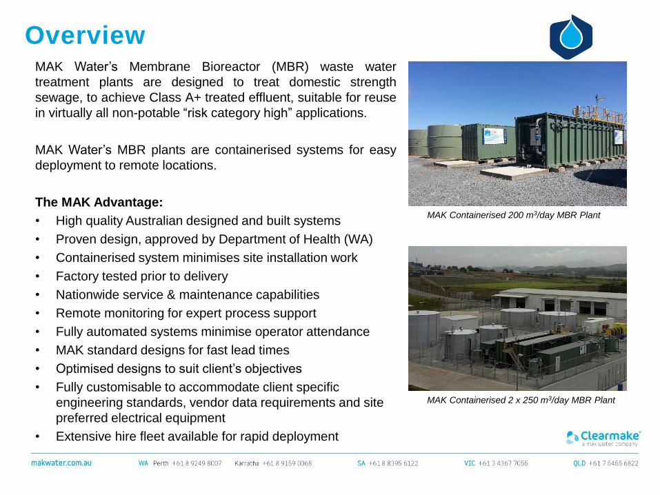
Anoxic Tank
The screened sewage from the micro screen flows into the Anoxic Tank, which allows nitrate-specific
bacteria to use nitrate (NO3) as an oxygen source and a nutrient in a process called denitrification.
De-nitrification occurs when oxygen levels are depleted and nitrate becomes the primary oxygen source
for microorganisms. The process is performed under anoxic conditions, when the dissolved oxygen
concentration is less than 0.5 mg/L, ideally less than 0.2 mg/L. When bacteria break apart nitrate (NO3-)
to gain the oxygen (O2), the nitrate is reduced to nitrous oxide (N2O), and turns to nitrogen gas (N2).
Since nitrogen gas has low water solubility, it escapes into the atmosphere as gas bubbles. Free
nitrogen is the major component of air, thus its release does not cause any environmental concern.
The tank is fitted with a submersible mixer, with guide rail and lifting chain for maintenance.
Micro
Screen
Waste
Bin
Anoxic
Zone
with
Mixer

Process Steps
Balance
Tank(s)
Raw
sewage
Anoxic Tank
The anoxic tank is enriched with returned activated sludge (RAS) from the Aerobic Tank’s MLR pump, to
provide a plentiful supply of food for the bacteria
Coagulant is used to react with orthophosphates to form phosphate precipitates. This reaction is very
rapid. The coagulant will also react with the alkalinity in the wastewater to form water insoluble
hydroxides. These insoluble salts will deposit onto the sludge particles, which are removed from the
treatment system with the excess sludge (WAS).
Where ClearAccessTM remote monitoring is installed, the ORP is continuously monitored; an alarm is
generated by any abnormal readings.
Micro
Screen
Waste
Bin
Anoxic
Zone
with
Mixer
RAS
Coagulant Dosing

Process Steps
Balance
Tank(s)
Raw
sewage
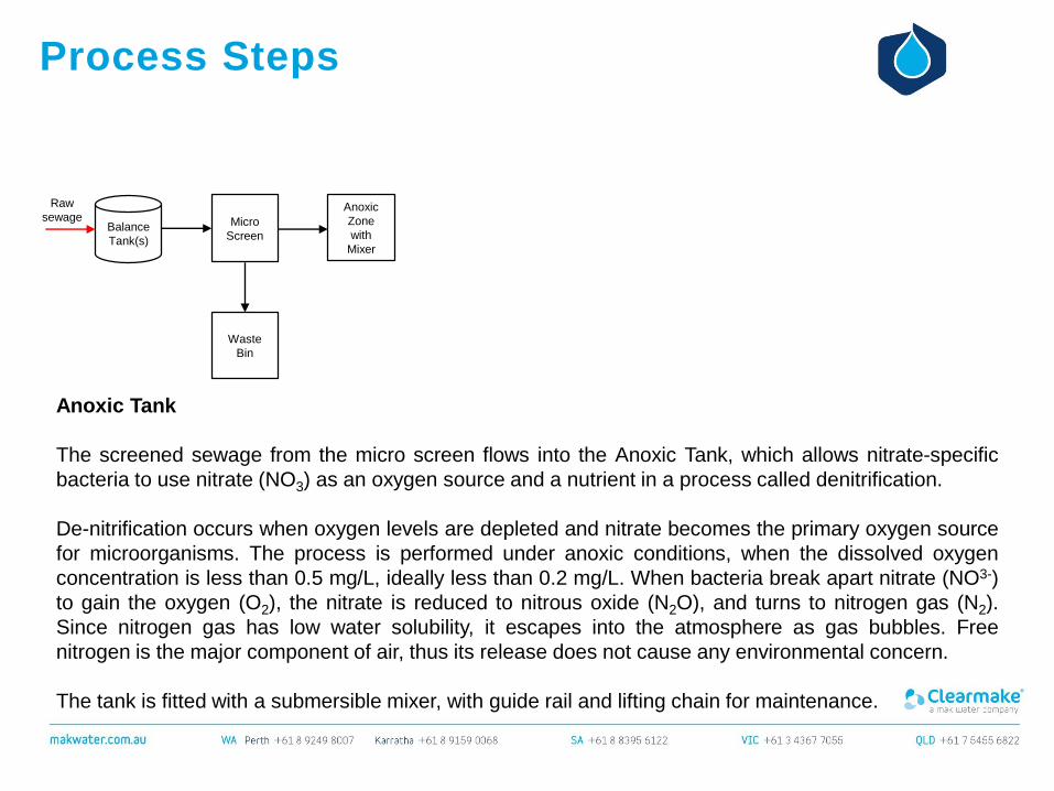
Aerobic Tank
BOD removal and nitrification occurs in the aerobic zone. Wastewater overflows from the anoxic zone to
the aerobic zone. Air is introduced into the aerobic zone through fine bubble diffusers, located on the
tank floor, by the dedicated aeration blower.
The autotrophic bacteria oxidize inorganic nitrogen components to obtain energy for growth and
maintenance, while they remove a majority of the colloidal contaminants present in the waste water by
converting them into carbon dioxide and biological floc.
Nitrification is a two-step process. Bacteria known as Nitrosomonas convert ammonia and ammonium to
nitrite. Next, bacteria called Nitrobacter finish the conversion of nitrite to nitrate.
Micro
Screen
Waste
Bin
Anoxic
Zone
with
Mixer
RAS
Coagulant Dosing
Aerobic
Zone
with
MLR
Pump
Aeration
blower
Process Steps
Balance
Tank(s)
Raw
sewage
Aerobic Tank
On a continuous basis, the Mixed Liquor Return (MLR) pump recirculates the Mixed Liquor Suspended
Solids (MLSS) around the bioreactor. A certain portion of activated sludge is periodically removed or
“wasted” from the biological system in order to maintain a pre-selected sludge age in the Biological
Tanks. Activated bio-solids (sludge) are transferred through the dedicated Waste Activated Sludge
(WAS) pipeline to the sludge tank.
The aerobic tank level, RAS and WAS flow rates are continuously monitored; alarms are generated by
any abnormal readings.
Where ClearAccessTM remote monitoring is installed, a Dissolved Oxygen (DO) analyser continuously
monitors the oxygen level, with the PLC automatically controlling the speed of the blower.
Micro
Screen
Waste
Bin
Anoxic
Zone
with
Mixer
RAS
Coagulant Dosing
Aerobic
Zone
with
MLR
Pump
WAS
Aeration
blower
To Sludge
Tank
Sludge
Tank
WAS

Process Steps
Balance
Tank(s)
Raw
sewage
Ultra Filtration
MAK Water's MBR plants utilise Berghof Biopulse technology, which makes use of the unique feature of
the HyMem 8 mm PVDF LE (Low Energy) membrane: it can be backwashed.
Mixed Liquor Suspended Solid (MLSS) from the bioreactor is pumped, at an optimized flow rate,
through the externally mounted cross flow Ultra Filtration (UF) membranes, which separate the bio-
solids from the liquid by means of filtration.
The cross-flow filtration method creates turbulence on the membrane surface, thereby hindering the
accumulation of retained particles. A high flow speed at the membrane surface carries the particles back
into the main flow, thereby minimizing the formation of the coating layer.
Micro
Screen
Waste
Bin
Anoxic
Zone
with
Mixer
RAS
Coagulant Dosing
Aerobic
Zone
with
MLR
Pump
WAS
Aeration
blower
To Sludge
Tank
Sludge
Tank
WAS
UF
(cross
flow)
CEB &
CIP
Tank
Process Steps
Balance
Tank(s)
Raw
sewage
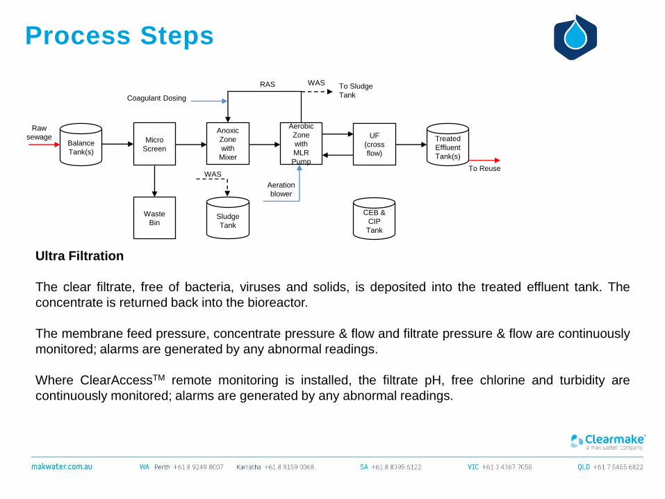
Ultra Filtration
The clear filtrate, free of bacteria, viruses and solids, is deposited into the treated effluent tank. The
concentrate is returned back into the bioreactor.
The membrane feed pressure, concentrate pressure & flow and filtrate pressure & flow are continuously
monitored; alarms are generated by any abnormal readings.
Where ClearAccessTM remote monitoring is installed, the filtrate pH, free chlorine and turbidity are
continuously monitored; alarms are generated by any abnormal readings.
Micro
Screen
Waste
Bin
Anoxic
Zone
with
Mixer
RAS
Coagulant Dosing
Aerobic
Zone
with
MLR
Pump
WAS
Aeration
blower
To Sludge
Tank
Sludge
Tank
WAS
UF
(cross
flow)
Treated
Effluent
Tank(s)
To Reuse
CEB &
CIP
Tank
Process Steps
Balance
Tank(s)
Raw
sewage
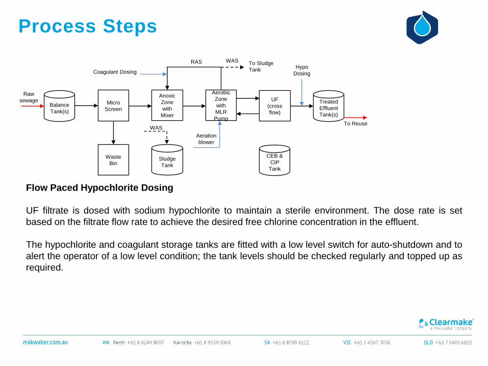
Flow Paced Hypochlorite Dosing
UF filtrate is dosed with sodium hypochlorite to maintain a sterile environment. The dose rate is set
based on the filtrate flow rate to achieve the desired free chlorine concentration in the effluent.
The hypochlorite and coagulant storage tanks are fitted with a low level switch for auto-shutdown and to
alert the operator of a low level condition; the tank levels should be checked regularly and topped up as
required.
Micro
Screen
Waste
Bin
Anoxic
Zone
with
Mixer
RAS
Coagulant Dosing
Aerobic
Zone
with
MLR
Pump
WAS
Aeration
blower
To Sludge
Tank
Sludge
Tank
WAS
UF
(cross
flow)
Treated
Effluent
Tank(s)
Hypo
Dosing
To Reuse
CEB &
CIP
Tank

CEB &
CIP
Tank
Process Steps
Balance
Tank(s)
Raw
sewage
Ultra Filtration – Auto Backwashing
An integrated automatic backwashing program controls the backwash cycles and backwash time in
order to ensure reliable operation.
The UF backwash pump takes suction from the CEB/CIP tank, which contains UF filtrate.
During normal filtration sequence, individual UF modules are automatically backwashed at a defined
frequency triggered by timer; backwashing can also be manually initiated via the HMI touch-screen.
The backwash pump discharge pressure & flow are continuously monitored; alarms are generated by
any abnormal readings.
Micro
Screen
Waste
Bin
Anoxic
Zone
with
Mixer
Aerobic
Zone
with
MLR
Pump
Sludge
Tank
UF
(cross
flow)
Treated
Effluent
Tank(s)
To Reuse
Process Steps
Balance
Tank(s)
Raw
sewage
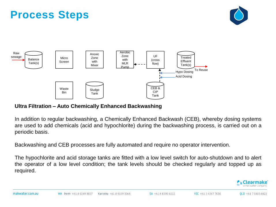
Ultra Filtration – Auto Chemically Enhanced Backwashing
In addition to regular backwashing, a Chemically Enhanced Backwash (CEB), whereby dosing systems
are used to add chemicals (acid and hypochlorite) during the backwashing process, is carried out on a
periodic basis.
Backwashing and CEB processes are fully automated and require no operator intervention.
The hypochlorite and acid storage tanks are fitted with a low level switch for auto-shutdown and to alert
the operator of a low level condition; the tank levels should be checked regularly and topped up as
required.
Micro
Screen
Waste
Bin
Anoxic
Zone
with
Mixer
Aerobic
Zone
with
MLR
Pump
Sludge
Tank
UF
(cross
flow)
Treated
Effluent
Tank(s)
Hypo Dosing
Acid Dosing
To Reuse
CEB &
CIP
Tank
Process Steps
Balance
Tank(s)
Raw
sewage
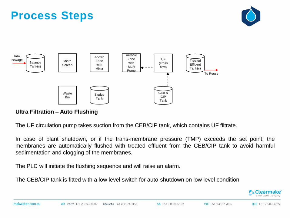
Ultra Filtration – Auto Flushing
The UF circulation pump takes suction from the CEB/CIP tank, which contains UF filtrate.
In case of plant shutdown, or if the trans-membrane pressure (TMP) exceeds the set point, the
membranes are automatically flushed with treated effluent from the CEB/CIP tank to avoid harmful
sedimentation and clogging of the membranes.
The PLC will initiate the flushing sequence and will raise an alarm.
The CEB/CIP tank is fitted with a low level switch for auto-shutdown on low level condition
Micro
Screen
Waste
Bin
Anoxic
Zone
with
Mixer
Aerobic
Zone
with
MLR
Pump
Sludge
Tank
UF
(cross
flow)
Treated
Effluent
Tank(s)
To Reuse
CEB &
CIP
Tank

Process Steps
Balance
Tank(s)
Raw
sewage
Ultra Filtration – CIP
A Clean In Place (CIP) system is provided for routine chemical cleaning of the UF membranes; the
chemical clean is a manually initiated function requiring an operator, whereby acid/alkaline chemicals
are manually added to the CEB/CIP tank and circulated around the membranes for a period of time.
Spent CIP solution is returned to the bioreactor.
A CIP membrane clean is typically performed on a semi-annual basis as part of a routine planned
maintenance procedure.
Micro
Screen
Waste
Bin
Anoxic
Zone
with
Mixer
Aerobic
Zone
with
MLR
Pump
Sludge
Tank
UF
(cross
flow)
Treated
Effluent
Tank(s)
To Reuse
CEB &
CIP
Tank
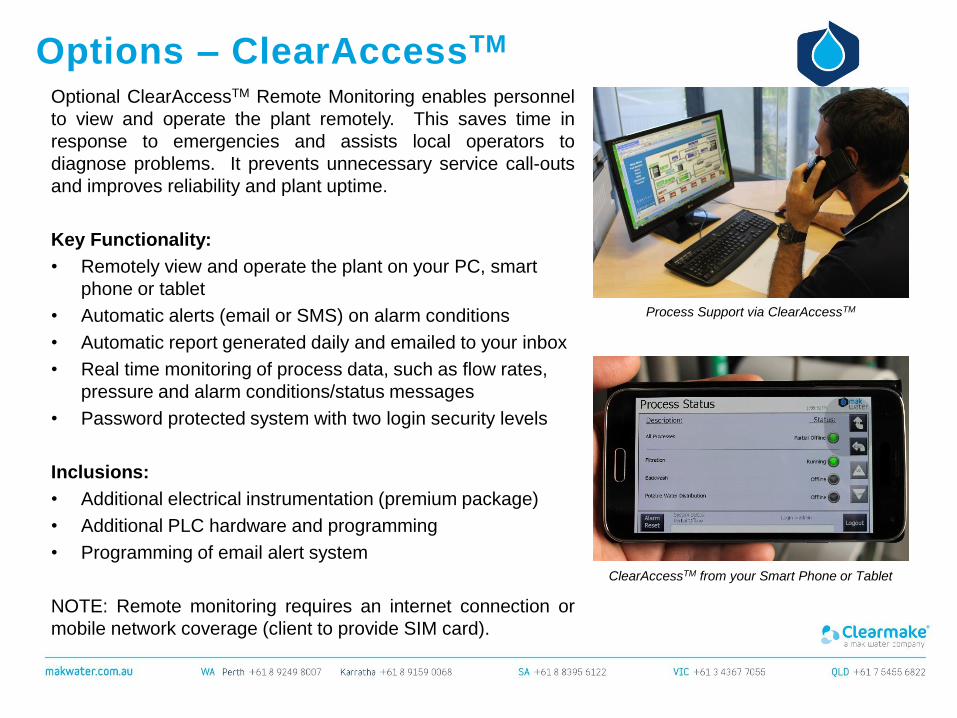
Options – ClearAccessTM
Optional ClearAccessTM Remote Monitoring enables personnel
to view and operate the plant remotely. This saves time in
response to emergencies and assists local operators to
diagnose problems. It prevents unnecessary service call-outs
and improves reliability and plant uptime.
Key Functionality:
• Remotely view and operate the plant on your PC, smart
phone or tablet
• Automatic alerts (email or SMS) on alarm conditions
• Automatic report generated daily and emailed to your inbox
• Real time monitoring of process data, such as flow rates,
pressure and alarm conditions/status messages
• Password protected system with two login security levels
Inclusions:
• Additional electrical instrumentation (premium package)
• Additional PLC hardware and programming
• Programming of email alert system
NOTE: Remote monitoring requires an internet connection or
mobile network coverage (client to provide SIM card).
Process Support via ClearAccessTM
ClearAccessTM from your Smart Phone or Tablet
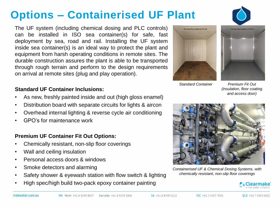
Options – Containerised UF PlantThe UF system (including chemical dosing and PLC controls)
can be installed in ISO sea container(s) for safe, fast
deployment by sea, road and rail. Installing the UF system
inside sea container(s) is an ideal way to protect the plant and
equipment from harsh operating conditions in remote sites. The
durable construction assures the plant is able to be transported
through rough terrain and perform to the design requirements
on arrival at remote sites (plug and play operation).
Standard UF Container Inclusions:
• As new, freshly painted inside and out (high gloss enamel)
• Distribution board with separate circuits for lights & aircon
• Overhead internal lighting & reverse cycle air conditioning
• GPO’s for maintenance work
Premium UF Container Fit Out Options:
• Chemically resistant, non-slip floor coverings
• Wall and ceiling insulation
• Personal access doors & windows
• Smoke detectors and alarming
• Safety shower & eyewash station with flow switch & lighting
• High spec/high build two-pack epoxy container painting
Standard Container Premium Fit Out
(insulation, floor coating
and access door)
Containerised UF & Chemical Dosing Systems, with
chemically resistant, non-slip floor coverings

Options – Salsnes Fine Screen Filter
The Salsnes Filter system can use used as a replacement for the Micro Screen, and provides a
significant advantage: the ability to dewater the sludge (10~20% dry matter) and thereby reduce
operating costs by eliminating the handling of sludge.
Three critical processes, solids separation, primary sludge thickening and dewatering are performed in
one compact unit that can completely replace conventional primary treatment and does so in a fraction
of the footprint, saving costs and valuable land space.
It does this by building a filter mat, particles larger than the mesh opening start the process by partially
blocking the mesh. This in turn traps smaller and smaller particles building the mat. Solids are gently
lifted from the effluent for thickening and dewatering. The unique air knife technology continually cleans
the mesh, continually presenting clean mesh to the effluent.
Options – Salsnes Fine Screen Filter
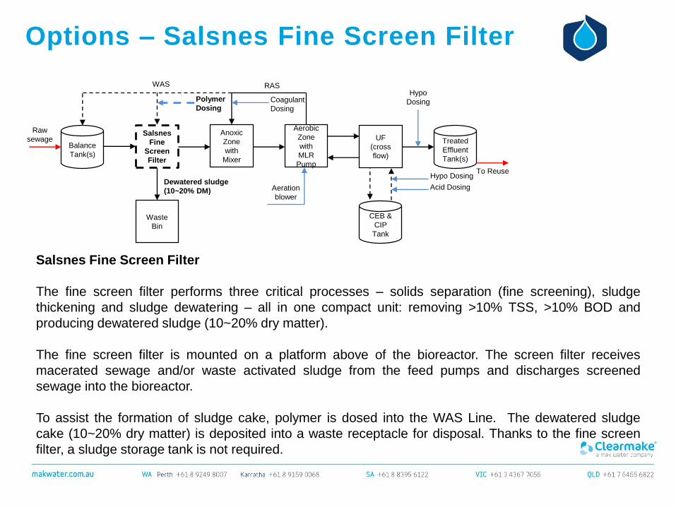
Salsnes Fine Screen Filter
The fine screen filter performs three critical processes – solids separation (fine screening), sludge
thickening and sludge dewatering – all in one compact unit: removing >10% TSS, >10% BOD and
producing dewatered sludge (10~20% dry matter).
The fine screen filter is mounted on a platform above of the bioreactor. The screen filter receives
macerated sewage and/or waste activated sludge from the feed pumps and discharges screened
sewage into the bioreactor.
To assist the formation of sludge cake, polymer is dosed into the WAS Line. The dewatered sludge
cake (10~20% dry matter) is deposited into a waste receptacle for disposal. Thanks to the fine screen
filter, a sludge storage tank is not required.
Balance
Tank(s)
Salsnes
Fine
Screen
Filter
Waste
Bin
Raw
sewageAnoxic
Zone
with
Mixer
UF
(cross
flow)
Aeration
blower
Hypo Dosing
Acid Dosing
RASWAS
Coagulant
Dosing
Dewatered sludge
(10~20% DM)
Polymer
Dosing
CEB &
CIP
Tank
Treated
Effluent
Tank(s)
Hypo
Dosing
To Reuse
Aerobic
Zone
with
MLR
Pump
Options – Enhanced Nutrient Removal
Balance
Tank(s)
Raw
sewage
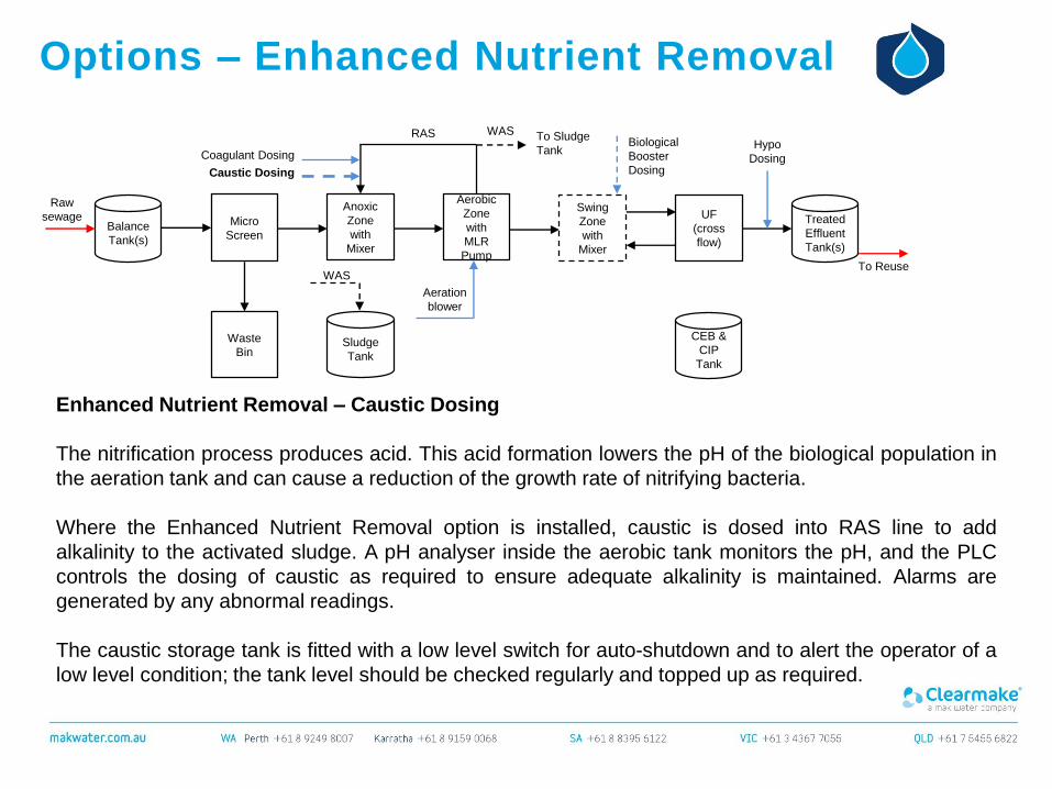
Enhanced Nutrient Removal – Caustic Dosing
The nitrification process produces acid. This acid formation lowers the pH of the biological population in
the aeration tank and can cause a reduction of the growth rate of nitrifying bacteria.
Where the Enhanced Nutrient Removal option is installed, caustic is dosed into RAS line to add
alkalinity to the activated sludge. A pH analyser inside the aerobic tank monitors the pH, and the PLC
controls the dosing of caustic as required to ensure adequate alkalinity is maintained. Alarms are
generated by any abnormal readings.
The caustic storage tank is fitted with a low level switch for auto-shutdown and to alert the operator of a
low level condition; the tank level should be checked regularly and topped up as required.
Micro
Screen
Waste
Bin
Anoxic
Zone
with
Mixer
RAS
Coagulant Dosing
Aerobic
Zone
with
MLR
Pump
WAS
Aeration
blower
To Sludge
Tank
Sludge
Tank
WAS
UF
(cross
flow)
Treated
Effluent
Tank(s)
Hypo
Dosing
To Reuse
Swing
Zone
with
Mixer
Biological
Booster
DosingCaustic Dosing
CEB &
CIP
Tank
Options – Enhanced Nutrient Removal
Balance
Tank(s)
Raw
sewage
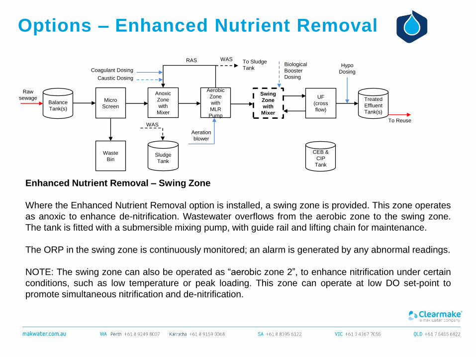
Enhanced Nutrient Removal – Swing Zone
Where the Enhanced Nutrient Removal option is installed, a swing zone is provided. This zone operates
as anoxic to enhance de-nitrification. Wastewater overflows from the aerobic zone to the swing zone.
The tank is fitted with a submersible mixing pump, with guide rail and lifting chain for maintenance.
The ORP in the swing zone is continuously monitored; an alarm is generated by any abnormal readings.
NOTE: The swing zone can also be operated as “aerobic zone 2”, to enhance nitrification under certain
conditions, such as low temperature or peak loading. This zone can operate at low DO set-point to
promote simultaneous nitrification and de-nitrification.
Micro
Screen
Waste
Bin
Anoxic
Zone
with
Mixer
RAS
Coagulant Dosing
Aerobic
Zone
with
MLR
Pump
WAS
Aeration
blower
To Sludge
Tank
Sludge
Tank
WAS
UF
(cross
flow)
Treated
Effluent
Tank(s)
Hypo
Dosing
To Reuse
Swing
Zone
with
Mixer
Biological
Booster
DosingCaustic Dosing
CEB &
CIP
Tank
Options – Enhanced Nutrient Removal
Balance
Tank(s)
Raw
sewage
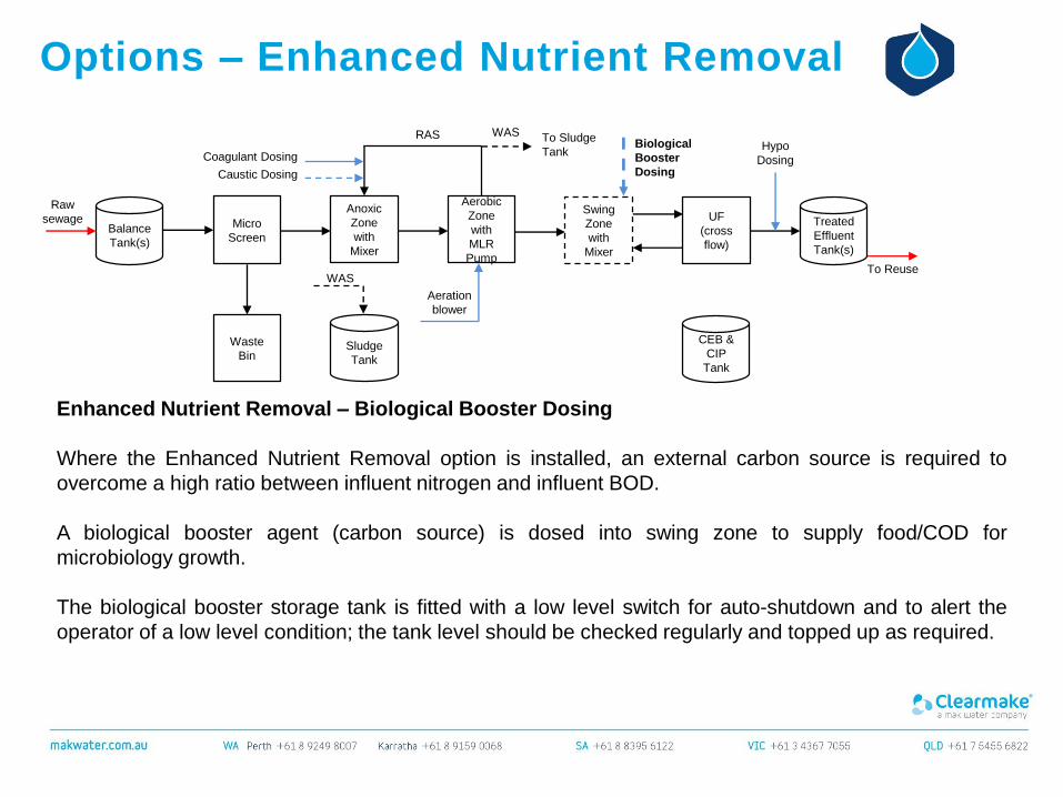
Enhanced Nutrient Removal – Biological Booster Dosing
Where the Enhanced Nutrient Removal option is installed, an external carbon source is required to
overcome a high ratio between influent nitrogen and influent BOD.
A biological booster agent (carbon source) is dosed into swing zone to supply food/COD for
microbiology growth.
The biological booster storage tank is fitted with a low level switch for auto-shutdown and to alert the
operator of a low level condition; the tank level should be checked regularly and topped up as required.
Micro
Screen
Waste
Bin
Anoxic
Zone
with
Mixer
RAS
Coagulant Dosing
Aerobic
Zone
with
MLR
Pump
WAS
Aeration
blower
To Sludge
Tank
Sludge
Tank
WAS
UF
(cross
flow)
Treated
Effluent
Tank(s)
Hypo
Dosing
To Reuse
Swing
Zone
with
Mixer
Biological
Booster
DosingCaustic Dosing
CEB &
CIP
Tank

Options – Effluent Sterilisation
PLC Controlled (Residual Trim) Hypochlorite Dosing, with Recirculation & Monitoring
The recirculation pump circulates the contents of the effluent storage tank on a continuous basis; a
chlorine analyser monitors the free residual chlorine, and the PLC controls dosing of sodium
hypochlorite as required to ensure correct free chlorine levels are maintained in the tank at all times.
Alarms are generated by any abnormal readings.
The hypochlorite storage tank is fitted with a low level switch for auto-shutdown and to alert the operator
of a low level condition; the tank level should be checked regularly and topped up as required.
Balance
Tank(s)
Raw
sewage Micro
Screen
Waste
Bin
Anoxic
Zone
with
Mixer
RAS
Coagulant Dosing
Aerobic
Zone
with
MLR
Pump
WAS
Aeration
blower
To Sludge
Tank
Sludge
Tank
WAS
UF
(cross
flow)
Hypo
Dosing
CEB &
CIP
Tank
Treated
Effluent
Tank(s)
To Reuse
Recirculation
Options – Effluent Sterilisation
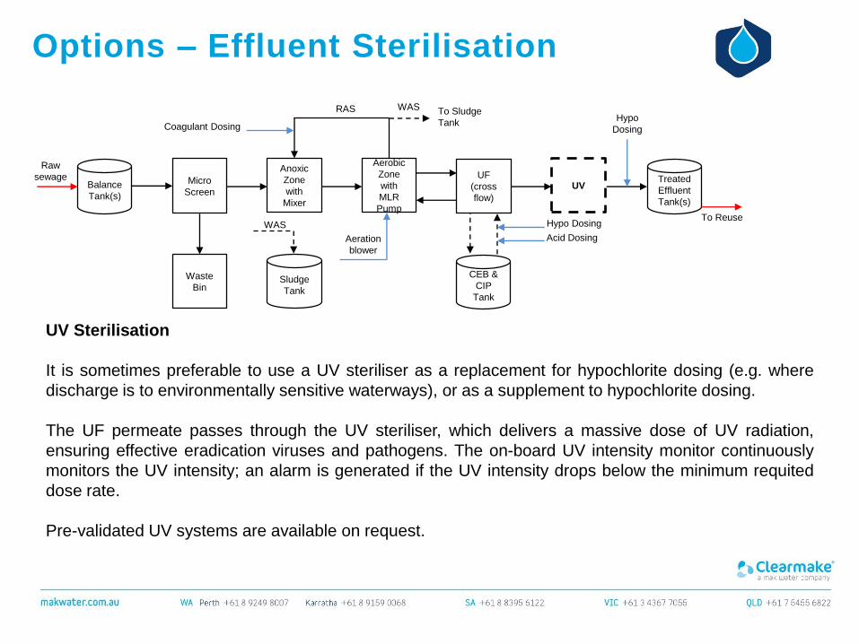
UV Sterilisation
It is sometimes preferable to use a UV steriliser as a replacement for hypochlorite dosing (e.g. where
discharge is to environmentally sensitive waterways), or as a supplement to hypochlorite dosing.
The UF permeate passes through the UV steriliser, which delivers a massive dose of UV radiation,
ensuring effective eradication viruses and pathogens. The on-board UV intensity monitor continuously
monitors the UV intensity; an alarm is generated if the UV intensity drops below the minimum requited
dose rate.
Pre-validated UV systems are available on request.
Balance
Tank(s)
Micro
Screen
Waste
Bin
Raw
sewageAnoxic
Zone
with
Mixer
UF
(cross
flow)
Aeration
blower
Hypo Dosing
Acid Dosing
Sludge
Tank
Coagulant Dosing
RAS WAS To Sludge
Tank
WAS
UV
CEB &
CIP
Tank
Treated
Effluent
Tank(s)
Hypo
Dosing
To Reuse
Aerobic
Zone
with
MLR
Pump

To Reuse
Options – Irrigation/Delivery Pump
Irrigation/Delivery Pump Set
A treated effluent delivery pump set can be provided to deliver treated water to end users.
The system typically is configured as a constant pressure system, with the capability to deliver variable
flow rates in response to downstream demand.
A pressure sensor is installed on the discharge manifold to automatically control the operation of the
pump.
Various options are available for pumping configurations (VSDs, standby pumps etc), and electrical
controls, to suit the client’s requirements.
Balance
Tank(s)
Raw
sewage Micro
Screen
Waste
Bin
Anoxic
Zone
with
Mixer
RAS
Coagulant Dosing
Aerobic
Zone
with
MLR
Pump
WAS
Aeration
blower
To Sludge
Tank
Sludge
Tank
WAS
UF
(cross
flow)
Treated
Effluent
Tank(s)
Hypo
Dosing
CEB &
CIP
Tank
Irrigation
/Delivery
Pump
Options – Membrane Integrity Testing
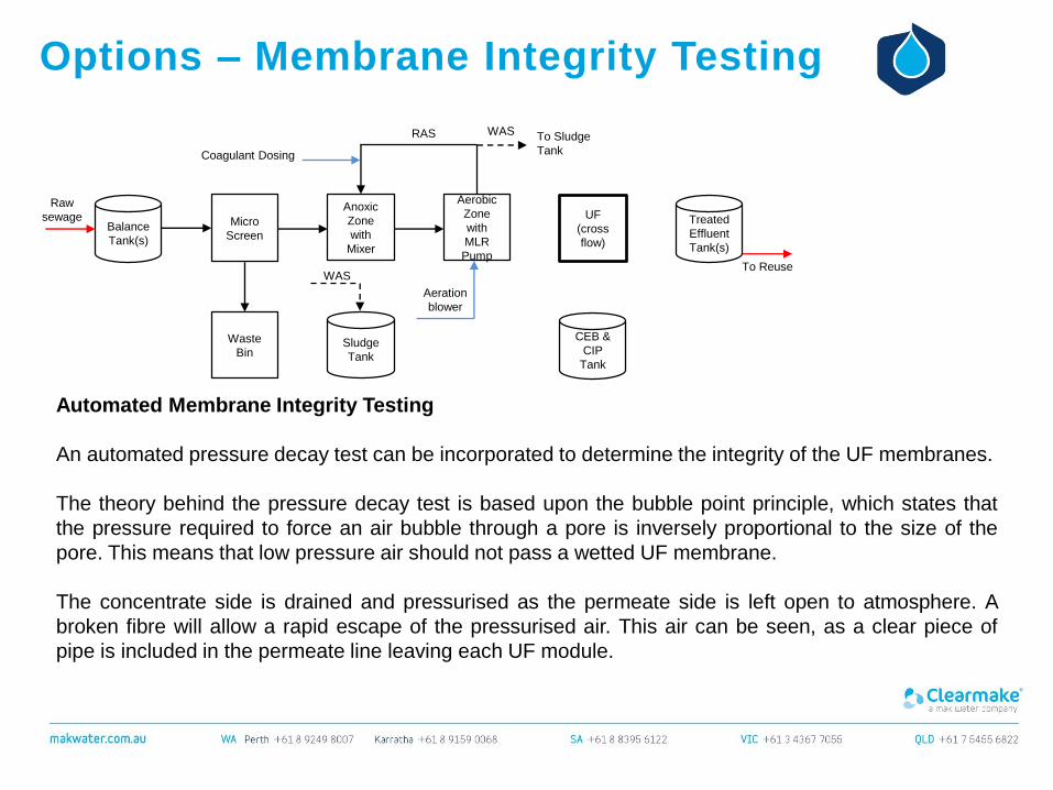
Automated Membrane Integrity Testing
An automated pressure decay test can be incorporated to determine the integrity of the UF membranes.
The theory behind the pressure decay test is based upon the bubble point principle, which states that
the pressure required to force an air bubble through a pore is inversely proportional to the size of the
pore. This means that low pressure air should not pass a wetted UF membrane.
The concentrate side is drained and pressurised as the permeate side is left open to atmosphere. A
broken fibre will allow a rapid escape of the pressurised air. This air can be seen, as a clear piece of
pipe is included in the permeate line leaving each UF module.
Balance
Tank(s)
Micro
Screen
Waste
Bin
Raw
sewageAnoxic
Zone
with
Mixer
UF
(cross
flow)
Aeration
blower
Sludge
Tank
Coagulant Dosing
RAS WAS To Sludge
Tank
WAS
CEB &
CIP
Tank
Treated
Effluent
Tank(s)
To Reuse
Aerobic
Zone
with
MLR
Pump
Options – Membrane Integrity Testing
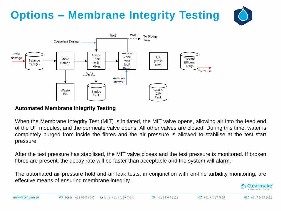
Automated Membrane Integrity Testing
When the Membrane Integrity Test (MIT) is initiated, the MIT valve opens, allowing air into the feed end
of the UF modules, and the permeate valve opens. All other valves are closed. During this time, water is
completely purged from inside the fibres and the air pressure is allowed to stabilise at the test start
pressure.
After the test pressure has stabilised, the MIT valve closes and the test pressure is monitored. If broken
fibres are present, the decay rate will be faster than acceptable and the system will alarm.
The automated air pressure hold and air leak tests, in conjunction with on-line turbidity monitoring, are
effective means of ensuring membrane integrity.
Balance
Tank(s)
Micro
Screen
Waste
Bin
Raw
sewageAnoxic
Zone
with
Mixer
UF
(cross
flow)
Aeration
blower
Sludge
Tank
Coagulant Dosing
RAS WAS To Sludge
Tank
WAS
CEB &
CIP
Tank
Treated
Effluent
Tank(s)
To Reuse
Aerobic
Zone
with
MLR
Pump
Options – Odour Control
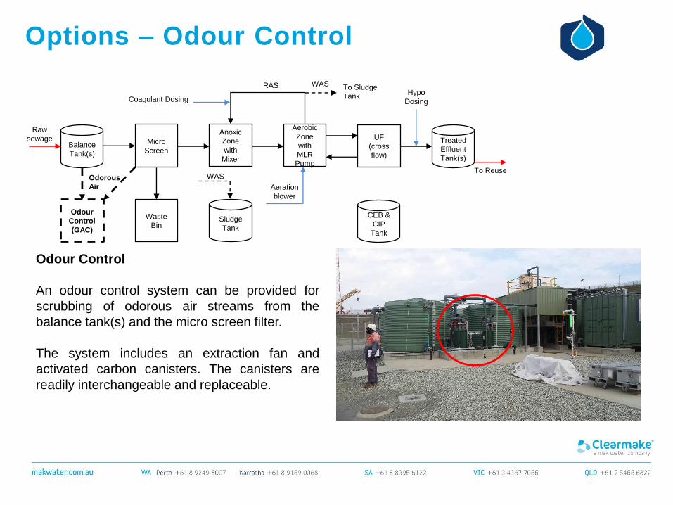
Odour Control
An odour control system can be provided for
scrubbing of odorous air streams from the
balance tank(s) and the micro screen filter.
The system includes an extraction fan and
activated carbon canisters. The canisters are
readily interchangeable and replaceable.
Balance
Tank(s)
Raw
sewage Micro
Screen
Waste
Bin
Anoxic
Zone
with
Mixer
RAS
Coagulant Dosing
Aerobic
Zone
with
MLR
Pump
WAS
Aeration
blower
To Sludge
Tank
Sludge
Tank
WAS
UF
(cross
flow)
CEB &
CIP
Tank
Treated
Effluent
Tank(s)
To Reuse
Hypo
Dosing
Odour
Control
(GAC)
Odorous
Air
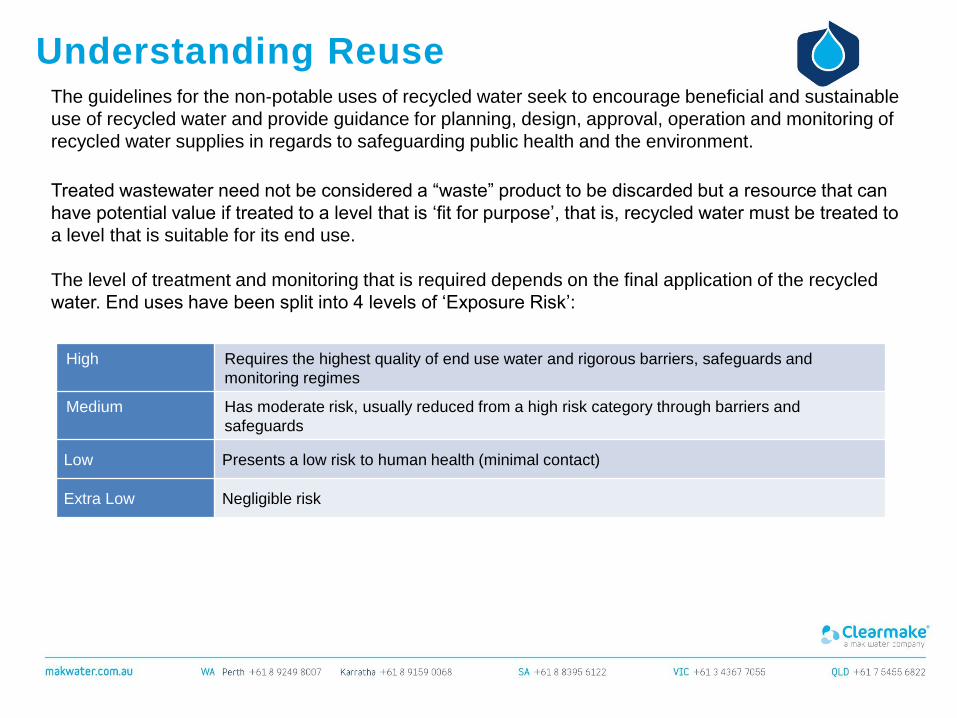
Understanding ReuseThe guidelines for the non-potable uses of recycled water seek to encourage beneficial and sustainable
use of recycled water and provide guidance for planning, design, approval, operation and monitoring of
recycled water supplies in regards to safeguarding public health and the environment.
Treated wastewater need not be considered a “waste” product to be discarded but a resource that can
have potential value if treated to a level that is ‘fit for purpose’, that is, recycled water must be treated to
a level that is suitable for its end use.
The level of treatment and monitoring that is required depends on the final application of the recycled
water. End uses have been split into 4 levels of ‘Exposure Risk’:
High Requires the highest quality of end use water and rigorous barriers, safeguards and
monitoring regimes
Medium Has moderate risk, usually reduced from a high risk category through barriers and
safeguards
Low Presents a low risk to human health (minimal contact)
Extra Low Negligible risk

Understanding ReuseThe MAK MBR WWTP produces treated effluent in compliance with “Risk Category High” of the
guidelines; the treated effluent is suitable for reuse in low, medium and high risk reuse applications.
Some “Low, Medium & High Risk” reuse applications include:
Exposure Risk Level Potential End Uses
High (Class A+) Multi dwellings; internal reuse (toilet flushing and dedicated cold water taps for
washing machines) or external surface irrigation
Agricultural irrigation of food crops consumed raw or unprocessed
Urban surface irrigation with unrestricted access and application
Fire fighting
Medium (Class A) Dust suppression
Wash down water
Cooling towers
Industrial use with potential human exposure
Urban surface irrigation with some restricted access and application
Fountains and water features
Stock watering, dairy cattle, grazing
Commercial food crops
Low (Class C)
Urban irrigation with enhanced restricted access and application*
Communal residential irrigation (sub-surface for fruit trees)
Agricultural irrigation; non-edible crops, fodder livestock
Subsoil irrigation
NOTE: The relevant health authorities may require an approved Recycled Water Quality Management
Plan to be in place, prior to authorising reuse of the treated effluent. MAK Water can provide this.
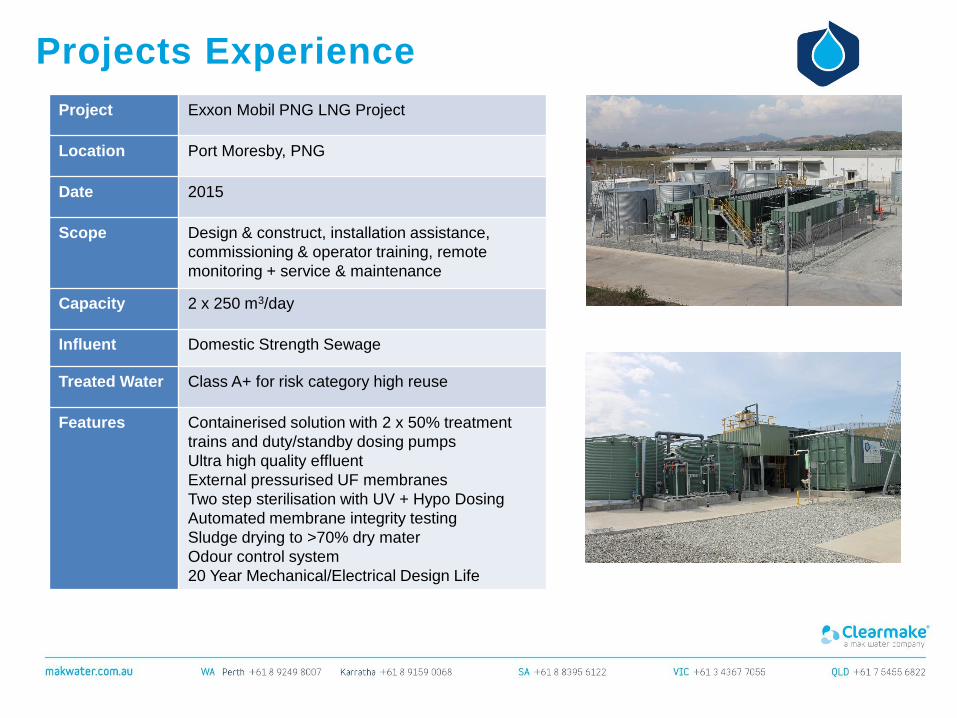
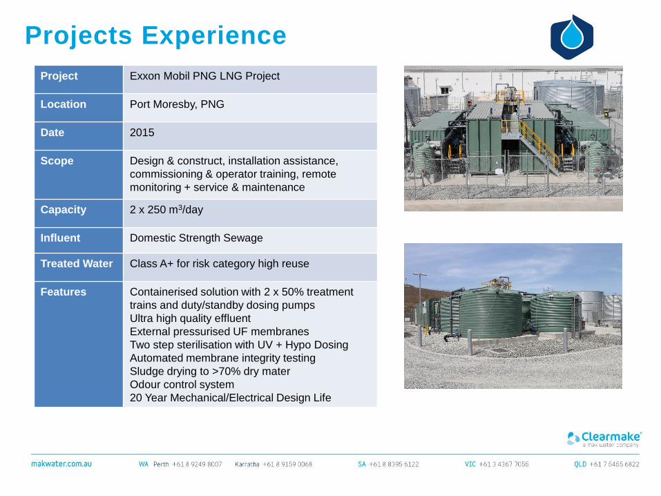
Projects Experience
Project Exxon Mobil PNG LNG Project
Location Port Moresby, PNG
Date 2015
Scope Design & construct, installation assistance,
commissioning & operator training, remote
monitoring + service & maintenance
Capacity 2 x 250 m3/day
Influent Domestic Strength Sewage
Treated Water Class A+ for risk category high reuse
Features Containerised solution with 2 x 50% treatment
trains and duty/standby dosing pumps
Ultra high quality effluent
External pressurised UF membranes
Two step sterilisation with UV + Hypo Dosing
Automated membrane integrity testing
Sludge drying to >70% dry mater
Odour control system
20 Year Mechanical/Electrical Design Life
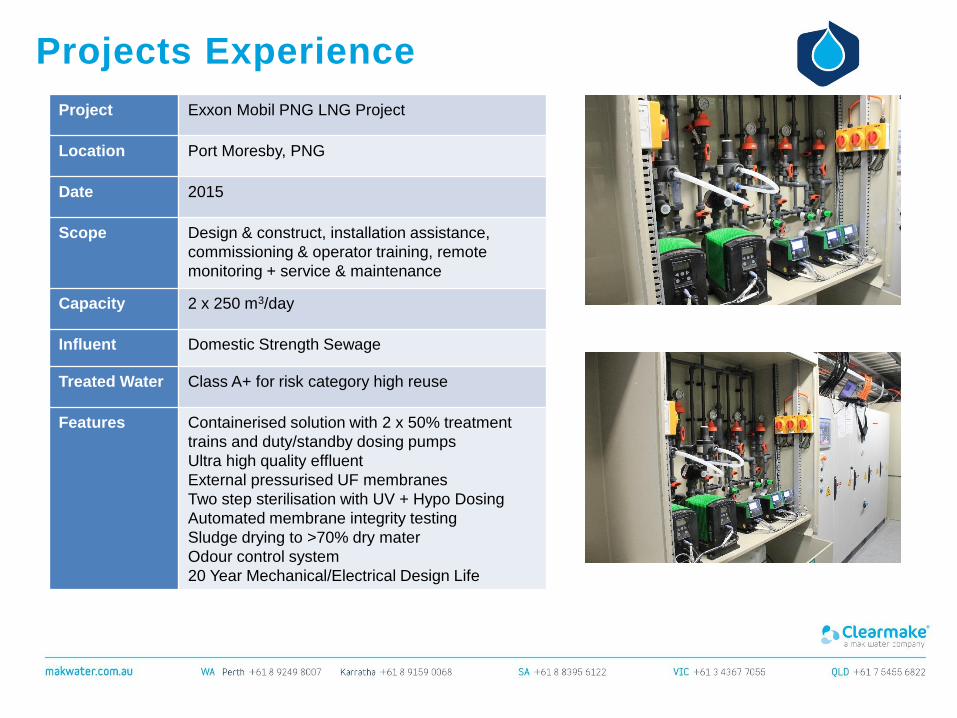
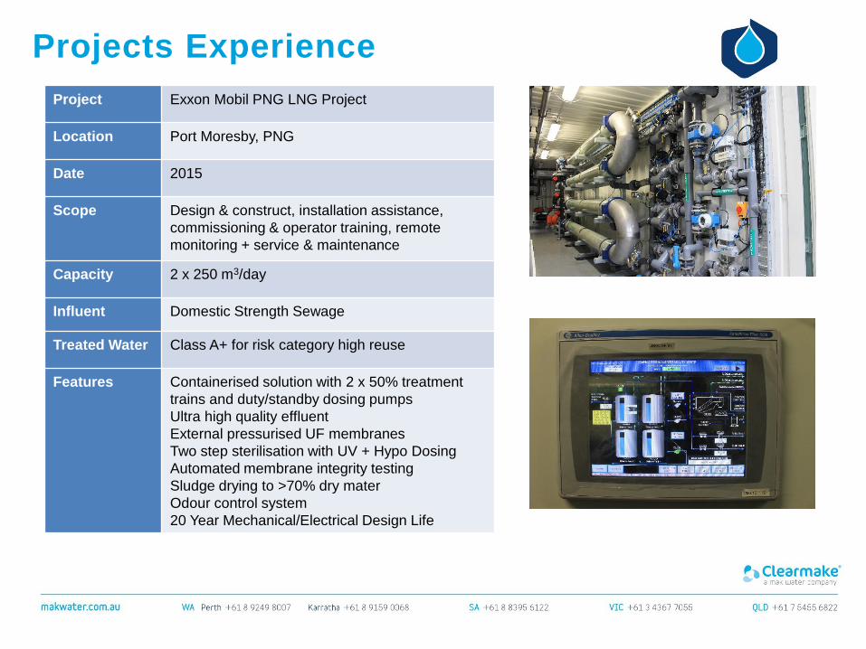
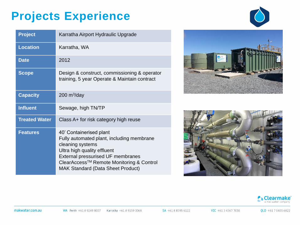
Projects Experience
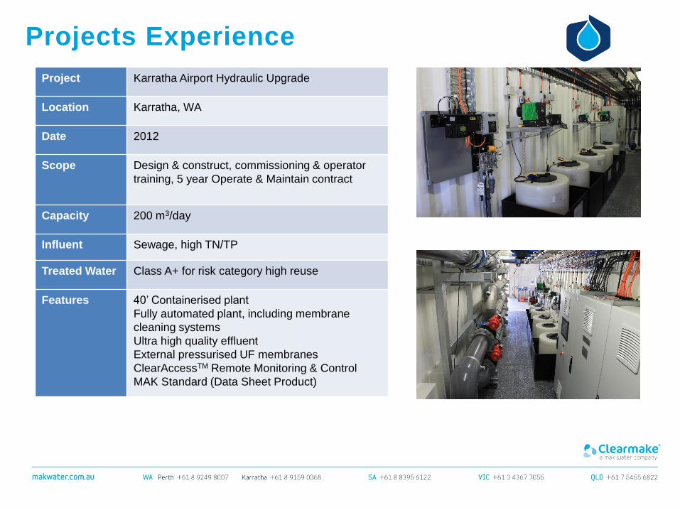
Project Karratha Airport Hydraulic Upgrade
Location Karratha, WA
Date 2012
Scope Design & construct, commissioning & operator
training, 5 year Operate & Maintain contract
Capacity 200 m3/day
Influent Sewage, high TN/TP
Treated Water Class A+ for risk category high reuse
Features 40’ Containerised plant
Fully automated plant, including membrane
cleaning systems
Ultra high quality effluent
External pressurised UF membranes
ClearAccessTM Remote Monitoring & Control
MAK Standard (Data Sheet Product)
Projects Experience
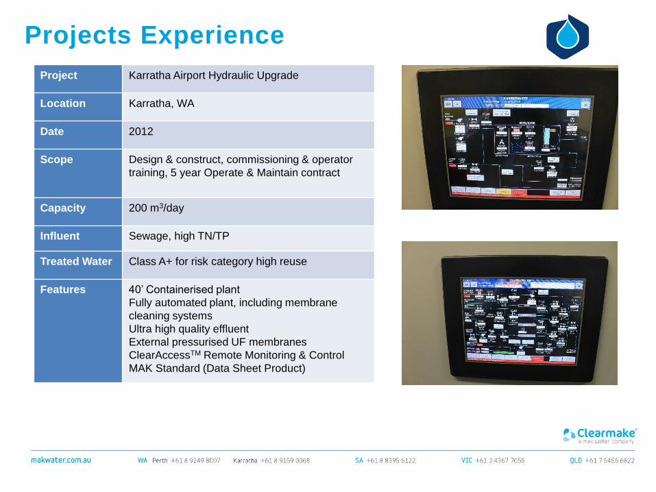
Project Karratha Airport Hydraulic Upgrade
Location Karratha, WA
Date 2012
Scope Design & construct, commissioning & operator
training, 5 year Operate & Maintain contract
Capacity 200 m3/day
Influent Sewage, high TN/TP
Treated Water Class A+ for risk category high reuse
Features 40’ Containerised plant
Fully automated plant, including membrane
cleaning systems
Ultra high quality effluent
External pressurised UF membranes
ClearAccessTM Remote Monitoring & Control
MAK Standard (Data Sheet Product)
Projects Experience
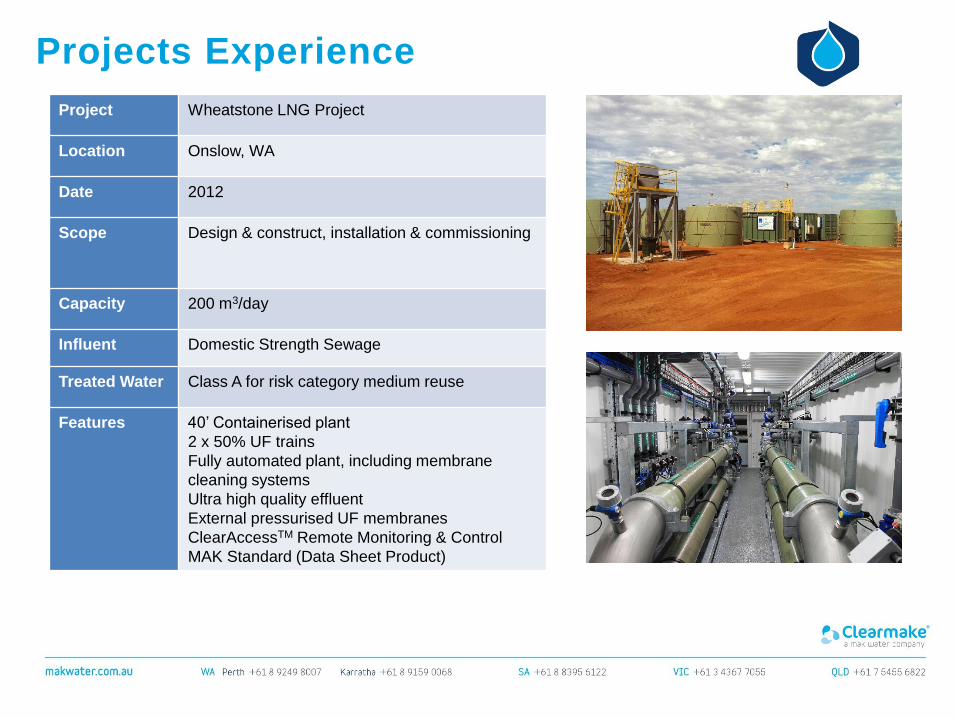
Project Wheatstone LNG Project
Location Onslow, WA
Date 2012
Scope Design & construct, installation & commissioning
Capacity 200 m3/day
Influent Domestic Strength Sewage
Treated Water Class A for risk category medium reuse
Features 40’ Containerised plant
2 x 50% UF trains
Fully automated plant, including membrane
cleaning systems
Ultra high quality effluent
External pressurised UF membranes
ClearAccessTM Remote Monitoring & Control
MAK Standard (Data Sheet Product)