PRODUCT NAME - RS Components
41
No.EX※※-OMP0013-B PRODUCT NAME SI unit for EtherNet/IP TM MODEL / Series / Product Number EX260-SEN#
Transcript of PRODUCT NAME - RS Components

No.EX※※-OMP0013-B
PRODUCT NAME
SI unit for EtherNet/IPTM
MODEL / Series / Product Number
EX260-SEN#

-1-
No.EX※※-OMP0013-B
Table of Contents
Safety Instructions 2 Model Indication and How to Order 8 Summary of Product elements 9
Definition and terminology 10 Installation and Wiring 11
Installation 11 Wiring 12
LED Indication and Settings 15 Hardware configuration 18
EDS file and icon 18 Setting using RSLogix5000TM 18 Setting using Network Configuration 23 EtherNet/IPTM Device Level Ring (DLR) function 28 EtherNet/IPTM QuickConnectTM function 28
Troubleshooting and Maintenance 30 Specifications 35
Specifications 35 Dimensions 38
Accessories 39
-2-
No.EX※※-OMP0013-B
Safety Instructions These safety instructions are intended to prevent hazardous situations and/or equipment damage. These instructions indicate the level of potential hazard with the labels of "Caution", "Warning" or "Danger". They are all important notes for safety and must be followed in addition to International standards (ISO/IEC) ∗1) and other safety regulations.
∗1) ISO 4414: Pneumatic fluid power -- General rules relating to systems. ISO 4413: Hydraulic fluid power -- General rules relating to systems. IEC 60204-1: Safety of machinery -- Electrical equipment of machines. (Part 1: General requirements) ISO 10218-1992: Manipulating industrial robots -Safety. etc.
Caution : CAUTION indicates a hazard with a low level of risk which, if not avoided, could result in minor or moderate injury.
Warning : WARNING indicates a hazard with a medium level of risk which, if not avoided, could result in death or serious injury.
Danger : DANGER indicates a hazard with a high level of risk which, if not avoided, will result in death or serious injury.
Warning 1. The compatibility of the product is the responsibility of the person who designs the
equipment or decides its specifications. Since the product specified here is used under various operating conditions, its compatibility with specific equipment must be decided by the person who designs the equipment or decides its specifications based on necessary analysis and test results. The expected performance and safety assurance of the equipment will be the responsibility of the person who has determined its compatibility with the product. This person should also continuously review all specifications of the product referring to its latest catalog information, with a view to giving due consideration to any possibility of equipment failure when configuring the equipment.
2. Only personnel with appropriate training should operate machinery and equipment. The product specified here may become unsafe if handled incorrectly. The assembly, operation and maintenance of machines or equipment including our products must be performed by an operator who is appropriately trained and experienced.
3. Do not service or attempt to remove product and machinery/equipment until safety is confirmed. 1. The inspection and maintenance of machinery/equipment should only be performed after measures
to prevent falling or runaway of the driven objects have been confirmed. 2. When the product is to be removed, confirm that the safety measures as mentioned above are
implemented and the power from any appropriate source is cut, and read and understand the specific product precautions of all relevant products carefully.
3. Before machinery/equipment is restarted, take measures to prevent unexpected operation and malfunction.
4. Contact SMC beforehand and take special consideration of safety measures if the product is to be used in any of the following conditions.
1. Conditions and environments outside of the given specifications, or use outdoors or in a place exposed to direct sunlight.
2. Installation on equipment in conjunction with atomic energy, railways, air navigation, space, shipping, vehicles, military, medical treatment, combustion and recreation, or equipment in contact with food and beverages, emergency stop circuits, clutch and brake circuits in press applications, safety equipment or other applications unsuitable for the standard specifications described in the product catalog.
3. An application which could have negative effects on people, property, or animals requiring special safety analysis.
4. Use in an interlock circuit, which requires the provision of double interlock for possible failure by using a mechanical protective function, and periodical checks to confirm proper operation.
-3-
No.EX※※-OMP0013-B
Caution The product is provided for use in manufacturing industries. The product herein described is basically provided for peaceful use in manufacturing industries. If considering using the product in other industries, consult SMC beforehand and exchange specifications or a contract if necessary. If anything is unclear, contact your nearest sales branch.
Limited warranty and Disclaimer/Compliance Requirements The product used is subject to the following "Limited warranty and Disclaimer" and "Compliance Requirements". Read and accept them before using the product.
Limited warranty and Disclaimer 1. The warranty period of the product is 1 year in service or 1.5 years after the product is delivered,
whichever is first.*2) Also, the product may have specified durability, running distance or replacement parts. Please consult your nearest sales branch.
2. For any failure or damage reported within the warranty period which is clearly our responsibility, a replacement product or necessary parts will be provided. This limited warranty applies only to our product independently, and not to any other damage incurred due to the failure of the product.
3. Prior to using SMC products, please read and understand the warranty terms and disclaimers noted in the specified catalog for the particular products.
∗2) Vacuum pads are excluded from this 1 year warranty. A vacuum pad is a consumable part, so it is warranted for a year after it is delivered. Also, even within the warranty period, the wear of a product due to the use of the vacuum pad or failure due to the deterioration of rubber material are not covered by the limited warranty.
Compliance Requirements
1. The use of SMC products with production equipment for the manufacture of weapons of mass destruction (WMD) or any other weapon is strictly prohibited.
2. The exports of SMC products or technology from one country to another are governed by the relevant security laws and regulation of the countries involved in the transaction. Prior to the shipment of a SMC product to another country, assure that all local rules governing that export are known and followed.
-4-
No.EX※※-OMP0013-B
Operator ♦This operation manual is intended for those who have knowledge of machinery using pneumatic
equipment, and have sufficient knowledge of assembly, operation and maintenance of such equipment. Only those persons are allowed to perform assembly, operation and maintenance.
♦Read and understand this operation manual carefully before assembling, operating or providing maintenance to the product.
■Safety Instructions
Warning ■Do not disassemble, modify (including changing the printed circuit board) or repair.
An injury or failure can result. ■Do not operate the product outside of the specifications.
Do not use for flammable or harmful fluids. Fire, malfunction, or damage to the product can result. Verify the specifications before use. ■Do not operate in an atmosphere containing flammable or explosive gases.
Fire or an explosion can result. This product is not designed to be explosion proof. ■If using the product in an interlocking circuit: •Provide a double interlocking system, for example a mechanical system. •Check the product regularly for proper operation. Otherwise malfunction can result, causing an accident. ■The following instructions must be followed during maintenance: •Turn off the power supply. •Stop the air supply, exhaust the residual pressure and verify that the air is released before performing maintenance.
Otherwise an injury can result.
Caution ■After maintenance is complete, perform appropriate functional inspections.
Stop operation if the equipment does not function properly. Safety cannot be assured in the case of unexpected malfunction. ■Provide grounding to assure the safety and noise resistance of the Serial System.
Individual grounding should be provided close to the product with a short cable.

-5-
No.EX※※-OMP0013-B
■NOTE ○Follow the instructions given below when designing, selecting and handling the product.
•The instructions on design and selection (installation, wiring, environment, adjustment, operation, maintenance, etc.) described below must also be followed. ∗Product specifications •When conformity to UL is required, the SI unit should be used with a UL1310 Class 2 power supply. •The SI unit is a “UL” approved product only if they have a mark on the body. •Use the specified voltage. Otherwise failure or malfunction can result.
•Reserve a space for maintenance. Allow sufficient space for maintenance when designing the system.
•Do not remove any nameplates or labels. This can lead to incorrect maintenance, or misreading of the operation manual, which could cause damage or malfunction to the product. It may also result in non-conformity to safety standards.

-6-
No.EX※※-OMP0013-B
•Product handling ∗Installation •Do not drop, hit or apply excessive shock to the fieldbus system. Otherwise damage to the product can result, causing malfunction.
•Tighten to the specified tightening torque. If the tightening torque is exceeded the mounting screws may be broken. IP67 protection cannot be guaranteed if the screws are not tightened to the specified torque.
•Never mount a product in a location that will be used as a foothold. The product may be damaged if excessive force is applied by stepping or climbing onto it.
∗Wiring •Avoid repeatedly bending or stretching the cables, or placing heavy load on them. Repetitive bending stress or tensile stress can cause breakage of the cable.
•Wire correctly. Incorrect wiring can break the product.
•Do not perform wiring while the power is on. Otherwise damage to the fieldbus system and/or I/O device can result, causing malfunction.
•Do not route wires and cables together with power or high voltage cables. Otherwise the fieldbus system and/or I/O device can malfunction due to interference of noise and surge voltage from power and high voltage cables to the signal line. Route the wires (piping) of the fieldbus system and/or I/O device separately from power or high voltage cables.
•Confirm proper insulation of wiring. Poor insulation (interference from another circuit, poor insulation between terminals, etc.) can lead to excess voltage or current being applied to the product, causing damage.
•Take appropriate measures against noise, such as using a noise filter, when the fieldbus system is incorporated into equipment. Otherwise noise can cause malfunction.
∗Environment •Select the proper type of protection according to the environment of operation. IP67 protection is achieved when the following conditions are met. (1) The units are connected properly with fieldbus cable with M12 connector and power cable with M12 (M8)
connector. (2) Suitable mounting of each unit and manifold valve. If using in an environment that is exposed to water splashes, please take measures such as using a cover.
•Do not use in a place where the product could be splashed by oil or chemicals. If the product is to be used in an environment containing oils or chemicals such as coolant or cleaning solvent, even for a short time, it may be adversely affected (damage, malfunction etc.).
•Do not use the product in an environment where corrosive gases or fluids could be splashed. Otherwise damage to the product and malfunction can result.
•Do not use in an area where surges are generated. If there is equipment which generates a large amount of surge (solenoid type lifter, high frequency induction furnace, motor, etc.) close to the fieldbus system, this may cause deterioration or breakage of the internal circuit of the fieldbus system. Avoid sources of surge generation and crossed lines.
•When a surge-generating load such as a relay or solenoid is driven directly, use an fieldbus system with a built-in surge absorbing element. Direct drive of a load generating surge voltage can damage the fieldbus system.
•The product is CE marked, but not immune to lightning strikes. Take measures against lightning strikes in the system.
•Prevent foreign matter such as remnant of wires from entering the fieldbus system to avoid failure and malfunction.

-7-
No.EX※※-OMP0013-B
•Mount the product in a place that is not exposed to vibration or impact. Otherwise failure or malfunction can result.
•Do not use the product in an environment that is exposed to temperature cycle. Heat cycles other than ordinary changes in temperature can adversely affect the inside of the product.
•Do not expose the product to direct sunlight. If using in a location directly exposed to sunlight, shade the product from the sunlight. Otherwise failure or malfunction can result.
•Keep within the specified ambient temperature range. Otherwise malfunction can result.
•Do not operate close to a heat source, or in a location exposed to radiant heat. Otherwise malfunction can result.
∗Adjustment and Operation •Perform settings suitable for the operating conditions. Incorrect setting can cause operation failure.
•Please refer to the PLC manufacturer's manual etc. for details of programming and addresses. For the PLC protocol and programming refer to the relevant manufacturer's documentation.
•The surface on the product may be hot.
∗Maintenance •Turn off the power supply, stop the supplied air, exhaust the residual pressure and verify the release of air before performing maintenance. There is a risk of unexpected malfunction.
•Perform regular maintenance and inspections. There is a risk of unexpected malfunction.
•After maintenance is complete, perform appropriate functional inspections. Stop operation if the equipment does not function properly. Otherwise safety is not assured due to an unexpected malfunction or incorrect operation.
•Do not use solvents such as benzene, thinner etc. to clean the each unit. They could damage the surface of the body and erase the markings on the body. Use a soft cloth to remove stains. For heavy stains, use a cloth soaked with diluted neutral detergent and fully squeezed, then wipe up the stains again with a dry cloth.
-8-
No.EX※※-OMP0013-B
Model Indication and How to Order
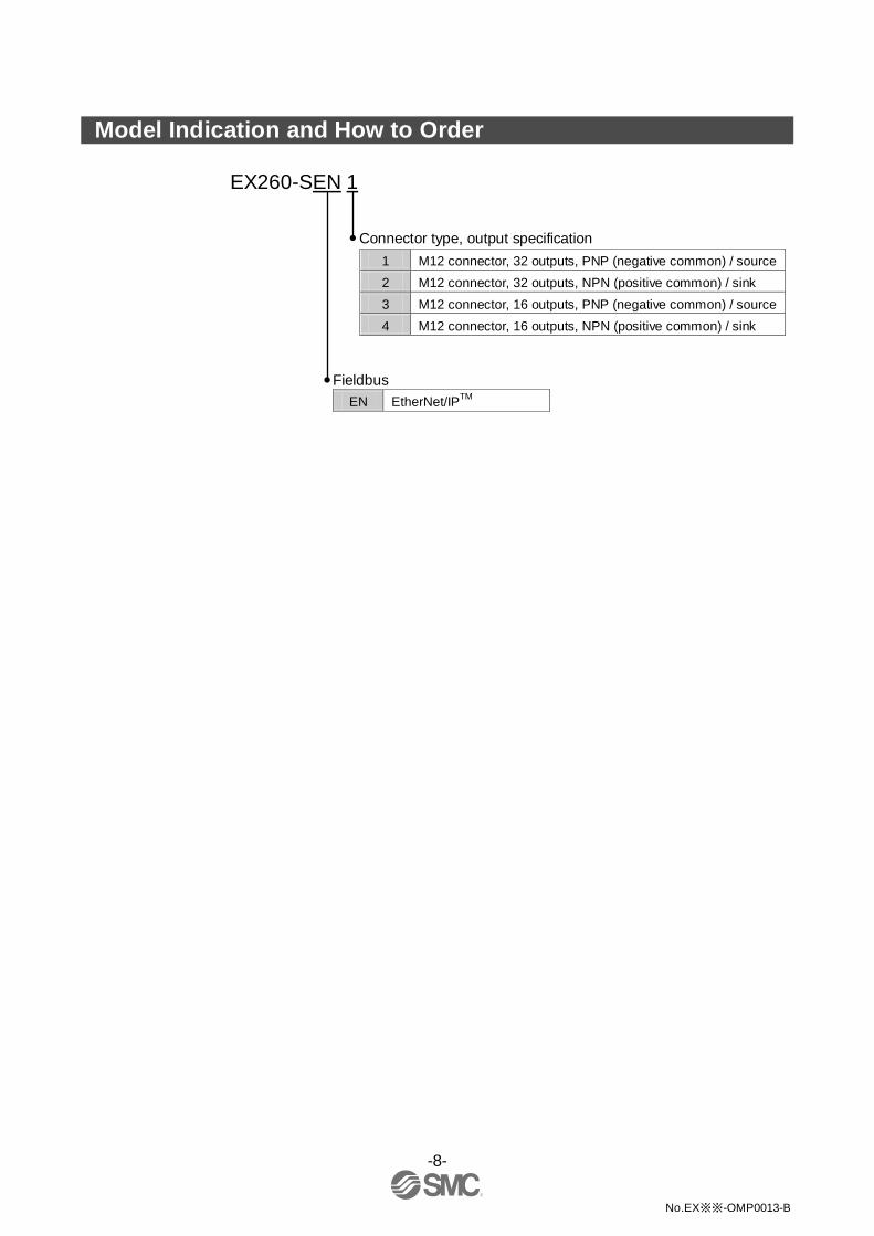
EX260-SEN 1
Connector type, output specification 1 M12 connector, 32 outputs, PNP (negative common) / source 2 M12 connector, 32 outputs, NPN (positive common) / sink 3 M12 connector, 16 outputs, PNP (negative common) / source 4 M12 connector, 16 outputs, NPN (positive common) / sink
Fieldbus EN EtherNet/IPTM
-9-
No.EX※※-OMP0013-B
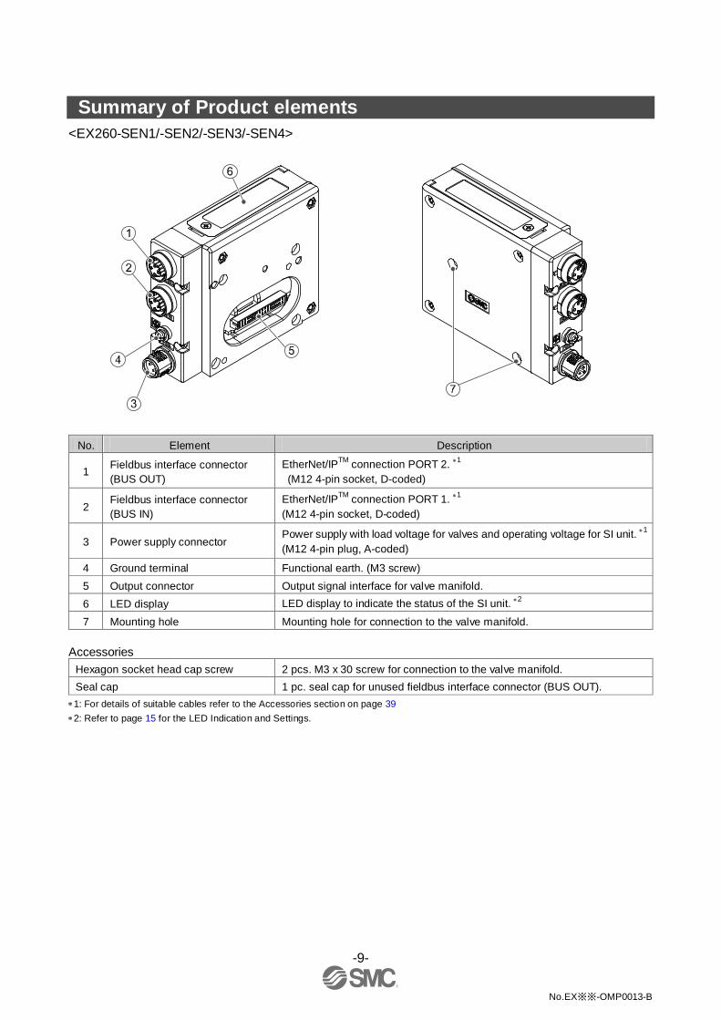
Summary of Product elements <EX260-SEN1/-SEN2/-SEN3/-SEN4>
No. Element Description
1 Fieldbus interface connector (BUS OUT)
EtherNet/IPTM connection PORT 2. ∗1 (M12 4-pin socket, D-coded)
2 Fieldbus interface connector (BUS IN)
EtherNet/IPTM connection PORT 1. ∗1 (M12 4-pin socket, D-coded)
3 Power supply connector Power supply with load voltage for valves and operating voltage for SI unit. ∗1
(M12 4-pin plug, A-coded)
4 Ground terminal Functional earth. (M3 screw) 5 Output connector Output signal interface for valve manifold. 6 LED display LED display to indicate the status of the SI unit. ∗2
7 Mounting hole Mounting hole for connection to the valve manifold. Accessories
Hexagon socket head cap screw 2 pcs. M3 x 30 screw for connection to the valve manifold. Seal cap 1 pc. seal cap for unused fieldbus interface connector (BUS OUT).
∗1: For details of suitable cables refer to the Accessories section on page 39 ∗2: Refer to page 15 for the LED Indication and Settings.
-10-
No.EX※※-OMP0013-B
■Definition and terminology
Terms Meaning 100 100BASE-TX Standard of LAN transmission line with communication speed of 100 Mbps. A
AD value The signal from the analogue input device is converted to digital, and displayed in decimal and hexadecimal. These hexadecimal and decimal values are also outputted to the analogue output device.
Auto negotiation The function that automatically optimizes the communication speed and method between the Ethernet devices.
C Current consumption The current necessary to operate each unit. D
DHCP The protocol which automatically set the information such as IP address which needs to be registered in order to use the network. Those information are set to each equipment which are connected to TCP/IP network.
DIN rail A metal rail conforming with DIN (German) standard.
DLR ∗ An abbreviation for Device Level Ring: Performs a fast switching of the communication route when any problem occurs with the Ring network, to maintain communication.
E EDS Settable attribute information of a device (each parameter’s object address, etc.)
stored on external disk.
Enclosure (IP□□) Abbreviation of international (ingress) protection. A standard related to the protection from external objects (hands, steel ball, steel wire, dust, water, etc.) applied to the product.
F Fieldbus
The protocol that uses digital communication to exchange signals between field equipment (instruments and actuators) running on site and a PLC.
Full duplex Communication system that can send and receive data at the same time bi-directionally
H Half duplex Communication system that sends and receives data in one direction at a time. I
IP address A 32 bit digit sequence which is assigned to identify devices which are connected to the network.
M MAC address A unique number inherent to all devices which are connected to EtherNet/IPTM.
Manifold A form consisting of multiple components. A form made by combining multiple components
N NPN output
The output type that uses an NPN transistor to operate output device. It is also known as a positive common type since a positive potential is applied to the power supply common line.
Number of outputs The number of points that can operate output device (solenoid valve) P
PLC Abbreviation of programmable logic controller. A digital computer used for automation of electromechanical processes.
PNP output The output type that uses a PNP transistor to operate output device. It is also known as a negative common type since a negative potential is applied to the power supply common line.
Q QuickConnectTM ∗ The function that reduces the time from the power being supplied to the equipment
operating and communication starting.
S SI unit Abbreviation of serial interface unit. A unit connected to a PLC to communicate
input and output data.
T Topology Connection configuration of the network ∗: Supported by the product version "Device Revision 2.1" manufactured in March 2013 or later. Products that were manufactured before
then do not support these functions.
-11-
No.EX※※-OMP0013-B
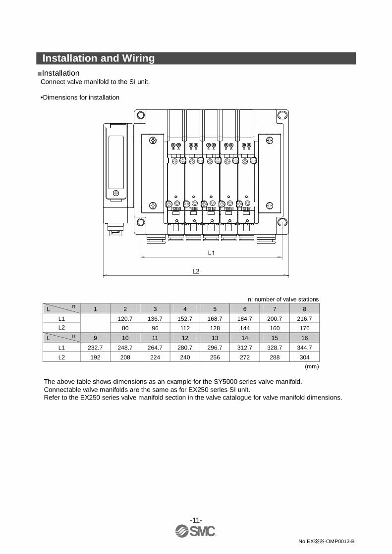
Installation and Wiring ■Installation Connect valve manifold to the SI unit.
•Dimensions for installation
n: number of valve stations L 1 2 3 4 5 6 7 8
L1
120.7 136.7 152.7 168.7 184.7 200.7 216.7 L2 80 96 112 128 144 160 176
L 9 10 11 12 13 14 15 16 L1 232.7 248.7 264.7 280.7 296.7 312.7 328.7 344.7 L2 192 208 224 240 256 272 288 304
(mm)
The above table shows dimensions as an example for the SY5000 series valve manifold. Connectable valve manifolds are the same as for EX250 series SI unit. Refer to the EX250 series valve manifold section in the valve catalogue for valve manifold dimensions.
n
n
-12-
No.EX※※-OMP0013-B
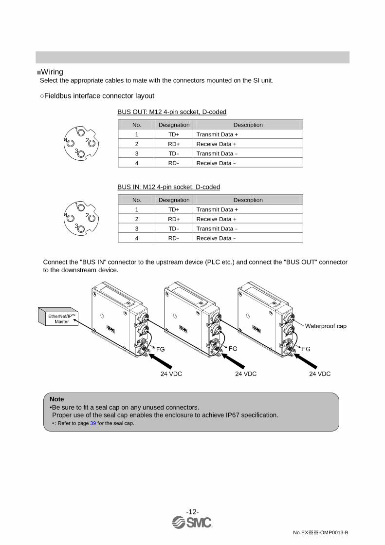
■Wiring Select the appropriate cables to mate with the connectors mounted on the SI unit.
○Fieldbus interface connector layout
BUS OUT: M12 4-pin socket, D-coded
No. Designation Description 1 TD+ Transmit Data + 2 RD+ Receive Data + 3 TD- Transmit Data - 4 RD- Receive Data -
BUS IN: M12 4-pin socket, D-coded
No. Designation Description 1 TD+ Transmit Data + 2 RD+ Receive Data + 3 TD- Transmit Data - 4 RD- Receive Data -
Connect the "BUS IN" connector to the upstream device (PLC etc.) and connect the "BUS OUT" connector to the downstream device.
Note •Be sure to fit a seal cap on any unused connectors. Proper use of the seal cap enables the enclosure to achieve IP67 specification. ∗: Refer to page 39 for the seal cap.

-13-
No.EX※※-OMP0013-B
○Power supply connector layout
PWR: M12 4-pin plug, A-coded
No. Designation Description 1 SI24 V +24 V for SI unit operation 2 SV24 V +24 V for solenoid valve 3 SI0 V 0 V for SI unit operation 4 SV0 V 0 V for solenoid valve
Power-supply line for solenoid valve and power-supply line for SI unit operation are isolated. Be sure to supply power, respectively. Either single-source power or two different power supplies can be used.
∗: Pay attention not to exceed the tolerance range of power supply vo ltage.

-14-
No.EX※※-OMP0013-B
○Ground terminal Connect the ground terminal to ground. Resistance to ground should be 100 ohms or less.
-15-
No.EX※※-OMP0013-B
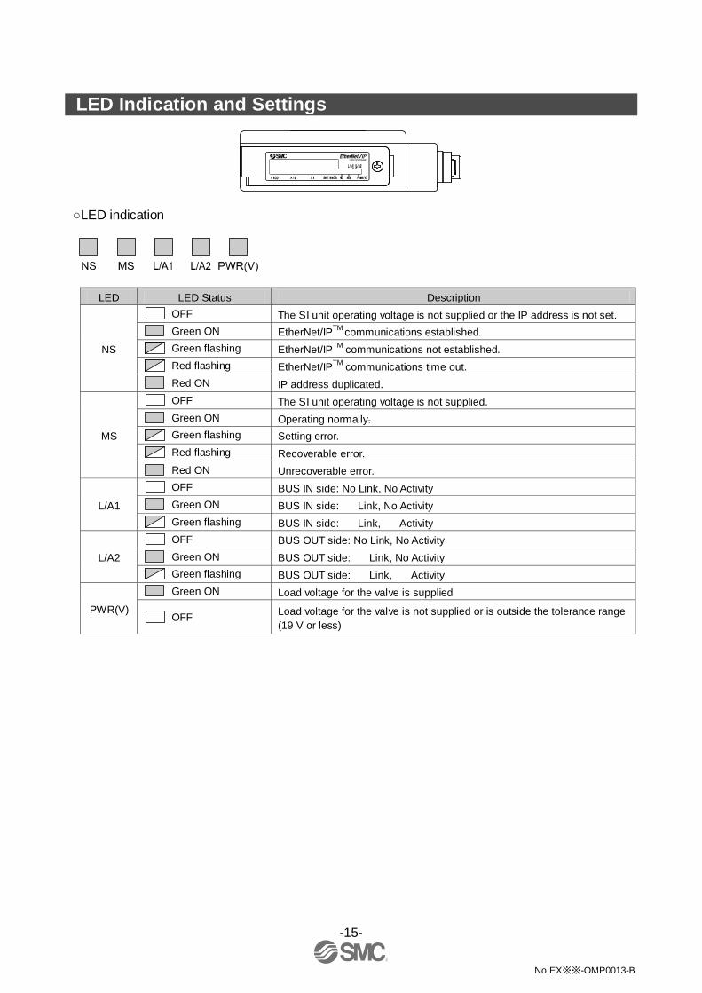
LED Indication and Settings
○LED indication
LED LED Status Description
NS
OFF The SI unit operating voltage is not supplied or the IP address is not set.
Green ON EtherNet/IPTM communications established.
Green flashing EtherNet/IPTM communications not established.
Red flashing EtherNet/IPTM communications time out.
Red ON IP address duplicated.
MS
OFF The SI unit operating voltage is not supplied.
Green ON Operating normally.
Green flashing Setting error.
Red flashing Recoverable error.
Red ON Unrecoverable error.
L/A1 OFF BUS IN side: No Link, No Activity
Green ON BUS IN side: Link, No Activity
Green flashing BUS IN side: Link, Activity
L/A2 OFF BUS OUT side: No Link, No Activity
Green ON BUS OUT side: Link, No Activity
Green flashing BUS OUT side: Link, Activity
PWR(V) Green ON Load voltage for the valve is supplied
OFF Load voltage for the valve is not supplied or is outside the tolerance range (19 V or less)
-16-
No.EX※※-OMP0013-B
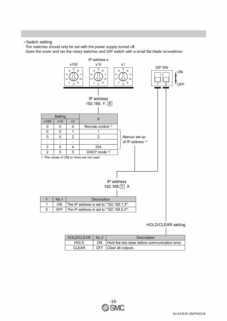
○Switch setting The switches should only be set with the power supply turned off. Open the cover and set the rotary switches and DIP switch with a small flat blade screwdriver.
-17-
No.EX※※-OMP0013-B
∗1: Remote control (IP Address X switch set to 000)
The mode to respond to the following commands of the BOOTP/DHCP Server, supplied by Rockwell Automation. Enable DHCP The IP address etc. can be obtained from the BOOTP/DHCP Server. If the power supply is switched off and on again in this state, the SI unit will obtain the IP address etc. again.
Disable BOOTP/DHCP The IP address etc. cannot be obtained from the BOOTP/DHCP Server. If the power supply is switched off and on again in this state, the previous settings will be maintained.
∗2: DHCP mode (IP Address X switch set to 255) The mode to obtain the IP address from the DHCP server. The IP address will be lost when the power supply is turned off.
∗3: Manual setting of IP address Manual setting of the IP address within the range 192.168.0.1 to 254, or 192.168.1.1 to 254.
Default setting The default settings are "Remote Control" and "Enable DHCP" mode.
Note •If the IP address of an SI unit is not known, set the mode to “DHCP mode” to reset the settings.

-18-
No.EX※※-OMP0013-B
Hardware configuration ■EDS file and icon The compatible EDS file is required to configure the SI unit within an EtherNet/IPTM network. Please download the latest EDS file from the following URL (http://www.smcworld.com). ∗: The method of installing the EDS file depends on the configuration software, so please refer to the configuration software manual.
EDS file
Product number File name Contents (EDS file and icon) 1 EX260-SEN1 ex260_sen1_24_v∗∗.zip ex260_sen1_24_v∗∗.eds ex260-sen1.ico
2 EX260-SEN2 ex260_sen2_24_v∗∗.zip ex260_sen2_24_v∗∗.eds ex260-sen2.ico
3 EX260-SEN3 ex260_sen3_22_v∗∗.zip ex260_sen3_22_v∗∗.eds ex260-sen3.ico 4 EX260-SEN4 ex260_sen4_22_v∗∗.zip ex260_sen4_22_v∗∗.eds ex260-sen4.ico
■Setting using RSLogix5000TM The method of connecting the SI unit with a Rockwell Automation EtherNet/IPTM (master) module is shown below. Refer to the RSLogix5000TM manual for further details.
∗: The screens shown below are based on using the Rockwell Automation RSLogix5000TM software. RSLogix5000TM is a trademark of Rockwell Automation.
For RSLogix5000TM, it is possible to perform settings without using the EDS file. ○Setting without using the EDS file •Select the master in the [I/O Configuration] folder, and select [New Module].

-19-
No.EX※※-OMP0013-B
•The Select Module Type screen will be displayed. Select [ETHERNET MODULE Generic Ethernet Module] and click on Create.
-20-
No.EX※※-OMP0013-B
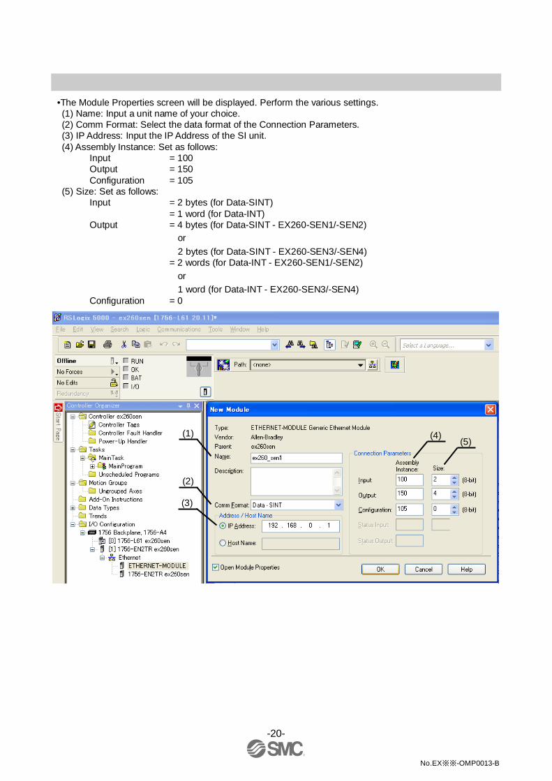
•The Module Properties screen will be displayed. Perform the various settings. (1) Name: Input a unit name of your choice. (2) Comm Format: Select the data format of the Connection Parameters. (3) IP Address: Input the IP Address of the SI unit. (4) Assembly Instance: Set as follows:
Input = 100 Output = 150 Configuration = 105
(5) Size: Set as follows: Input = 2 bytes (for Data-SINT)
= 1 word (for Data-INT) Output = 4 bytes (for Data-SINT - EX260-SEN1/-SEN2)
or 2 bytes (for Data-SINT - EX260-SEN3/-SEN4)
= 2 words (for Data-INT - EX260-SEN1/-SEN2) or 1 word (for Data-INT - EX260-SEN3/-SEN4)
Configuration = 0
(1) (4)
(2)
(3)
(5)

-21-
No.EX※※-OMP0013-B
○Setting using the EDS file ∗1 •Install in advance the EDS file using the Rockwell Automation software RSNetWorxTM for EtherNet/IPTM. Refer to the Manual for RSNetWorxTM for EtherNet/IPTM for installation instructions.
∗1: This function is supported by the EDS file Revision 2.0 for products manufactured in March 2013 or later (Device Revision 2.1). ∗2: RSNetWorxTM is a trademark of Rockwell Automation.
When the EDS file is installed, the SI unit number will be added in the Select Module screen. Select the SI unit number to be used, and click the Create button.
Example: "EX260-SEN1" is selected.

-22-
No.EX※※-OMP0013-B
•The Module Properties screen is displayed. Perform each setting. (1) Name: Enter the desired unit name. (2) IP Address: Enter the IP address that was set for the SI unit.
(1)
(2)
-23-
No.EX※※-OMP0013-B
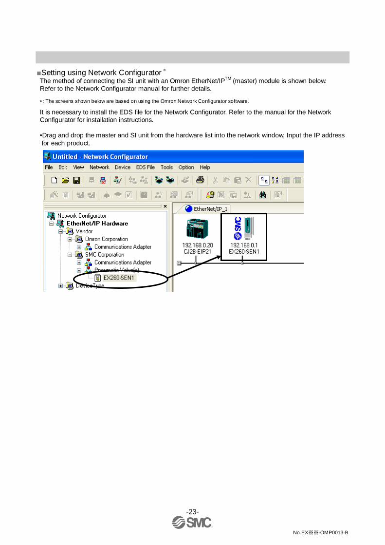
■Setting using Network Configurator ∗ The method of connecting the SI unit with an Omron EtherNet/IPTM (master) module is shown below. Refer to the Network Configurator manual for further details.
∗: The screens shown below are based on using the Omron Network Configurator software.
It is necessary to install the EDS file for the Network Configurator. Refer to the manual for the Network Configurator for installation instructions.
•Drag and drop the master and SI unit from the hardware list into the network window. Input the IP address for each product.

-24-
No.EX※※-OMP0013-B
•Double-click on the icon of the master to open the Edit Device Parameters window, and move the SI unit from the [Unregister Device List] to the [Register Device List].

-25-
No.EX※※-OMP0013-B
•Double click on the SI unit in the [Register Device List] to open the Edit Connection screen. For [Connection I/O Type], select [Exclusive Owner]. For the Originator Device, select an arbitrary [Input Tag Set] and [Output Tag Set], with the same number of bytes as the [Output Tag Set] and [Input Tag Set] in the Target Device, and register the Input / Output connections.
Input size = 2 bytes Output size = 4 bytes (for EX260-SEN1/-SEN2)
2 bytes (for EX260-SEN3/-SEN4)

-26-
No.EX※※-OMP0013-B
Example: Tag Set D00100 (2 bytes) to the Input, and D00150 (4 bytes) to the Output.

-27-
No.EX※※-OMP0013-B
•If the allocation has been correctly completed, the registered IP address will be displayed with the SI unit icon in the network window.
-28-
No.EX※※-OMP0013-B
■EtherNet/IPTM Device Level Ring (DLR) function ∗ This SI unit can be used as an EtherNet/IPTM compliant node for network rings with the DLR function. To enable the DLR function, all the ring nodes need to be applicable to the DLR function. Since all of the DLR function settings are performed by the Ring Supervisor, there is no need to perform any settings to the SI unit. Refer to the manual for the Ring Supervisor for detailed settings.
∗: Supported by the product version "Device Revision 2.1" manufactured in March 2013 or later. Products that were manufactured before then do not support these functions.
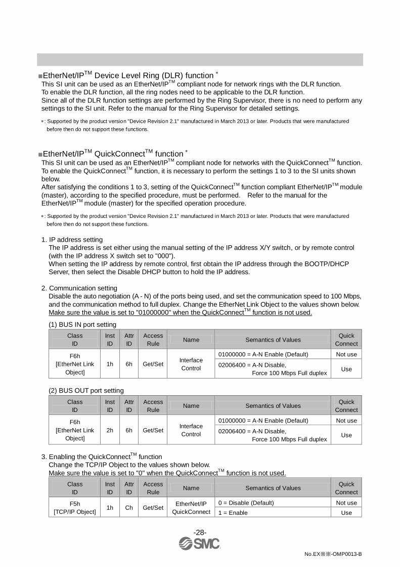
■EtherNet/IPTM QuickConnectTM function ∗ This SI unit can be used as an EtherNet/IPTM compliant node for networks with the QuickConnectTM function. To enable the QuickConnectTM function, it is necessary to perform the settings 1 to 3 to the SI units shown below. After satisfying the conditions 1 to 3, setting of the QuickConnectTM function compliant EtherNet/IPTM module (master), according to the specified procedure, must be performed. Refer to the manual for the EtherNet/IPTM module (master) for the specified operation procedure.
∗: Supported by the product version "Device Revision 2.1" manufactured in March 2013 or later. Products that were manufactured before then do not support these functions.
1. IP address setting
The IP address is set either using the manual setting of the IP address X/Y switch, or by remote control (with the IP address X switch set to "000"). When setting the IP address by remote control, first obtain the IP address through the BOOTP/DHCP Server, then select the Disable DHCP button to hold the IP address.
2. Communication setting
Disable the auto negotiation (A - N) of the ports being used, and set the communication speed to 100 Mbps, and the communication method to full duplex. Change the EtherNet Link Object to the values shown below. Make sure the value is set to "01000000" when the QuickConnectTM function is not used.
(1) BUS IN port setting Class
ID Inst ID
Attr ID
Access Rule Name Semantics of Values
Quick Connect
F6h [EtherNet Link
Object] 1h 6h Get/Set Interface
Control
01000000 = A-N Enable (Default) Not use
02006400 = A-N Disable, Force 100 Mbps Full duplex Use
(2) BUS OUT port setting
Class ID
Inst ID
Attr ID
Access Rule
Name Semantics of Values Quick Connect
F6h [EtherNet Link
Object] 2h 6h Get/Set
Interface Control
01000000 = A-N Enable (Default) Not use
02006400 = A-N Disable, Force 100 Mbps Full duplex
Use
3. Enabling the QuickConnectTM function
Change the TCP/IP Object to the values shown below. Make sure the value is set to "0" when the QuickConnectTM function is not used.
Class ID
Inst ID
Attr ID
Access Rule
Name Semantics of Values Quick Connect
F5h [TCP/IP Object]
1h Ch Get/Set EtherNet/IP QuickConnect
0 = Disable (Default) Not use 1 = Enable Use
-29-
No.EX※※-OMP0013-B
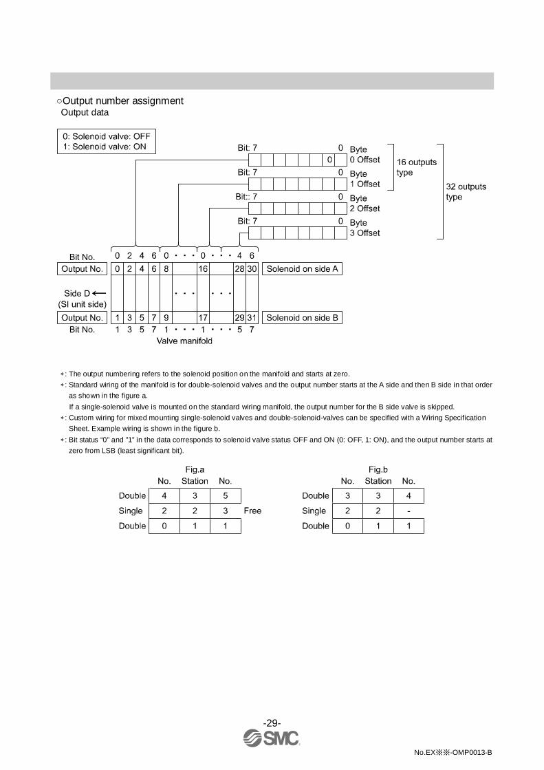
○Output number assignment Output data
∗: The output numbering refers to the solenoid position on the manifold and starts at zero. ∗: Standard wiring of the manifold is for double-solenoid valves and the output number starts at the A side and then B side in that order
as shown in the figure a. If a single-solenoid valve is mounted on the standard wiring manifold, the output number for the B side valve is skipped.
∗: Custom wiring for mixed mounting single-solenoid valves and double-solenoid-valves can be specified with a Wiring Specification Sheet. Example wiring is shown in the figure b.
∗: Bit status “0” and ”1” in the data corresponds to solenoid valve status OFF and ON (0: OFF, 1: ON), and the output number starts at zero from LSB (least significant bit).
-30-
No.EX※※-OMP0013-B
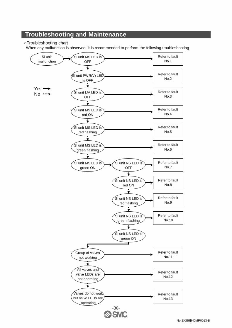
Troubleshooting and Maintenance ○Troubleshooting chart When any malfunction is observed, it is recommended to perform the following troubleshooting.
SI unit malfunction
Refer to fault No.1
Group of valves not working
SI unit PWR(V) LED is OFF
All valves and valve LEDs are not operating
SI unit MS LED is green flashing
SI unit NS LED is OFF
Refer to fault No.7
SI unit NS LED is red ON
SI unit NS LED is red flashing
SI unit NS LED is green flashing
SI unit MS LED is OFF
SI unit MS LED is red ON
SI unit MS LED is red flashing
Valves do not work but valve LEDs are
operating
SI unit MS LED is green ON
Refer to fault No.2
Refer to fault No.4
Refer to fault No.5
Refer to fault No.6
Refer to fault No.8
Refer to fault No.9
Refer to fault No.10
Refer to fault No.11
Refer to fault No.12
Refer to fault No.13
SI unit NS LED is green ON
Yes No
SI unit L/A LED is OFF
Refer to fault No.3

-31-
No.EX※※-OMP0013-B
Troubleshooting table
Fault No.1 Fault Probable cause Recommended error handling Recommended action
SI unit MS LED is OFF (Green / Red is OFF)
Defective power cable wiring for SI unit operation
Check the condition of the power cable wiring to the SI unit.
Re-tighten the power cable. (Replace the cable if it is broken)
Correct the power cable wiring layout.
SI unit operating voltage is not supplied
Check the condition of the supply voltage to the SI unit.
Supply 24 VDC ±10% to the SI unit.
Fault No.2
Fault Probable cause Recommended error handling Recommended action
SI unit PWR(V) LED is OFF
Defective power cable wiring for the solenoid valve
Check the condition of the power cable wiring for the valve.
Re-tighten the power cable. (Replace the cable if it is broken)
Correct the power cable wiring layout.
Load voltage for the valve is not supplied
Check the condition of the supply voltage for the valve.
Supply 24 VDC +10% / -5% to the valves.
Fault No.3
Fault Probable cause Recommended error handling Recommended action
SI unit L/A LED is OFF
EtherNet/IPTM communication error between the SI unit and the upstream EtherNet/IPTM device.
Check the status of the upstream EtherNet/IPTM device.
Supply power to the upstream EtherNet/IPTM device.
Check the BUS IN side communication cable connections and check for broken wires.
Tighten the communication cable connection. (Replace the cable if it is broken)
Check that there are no high voltage cables or equipment that generates noise around the communication cable and SI unit.
Take measures to keep the communication cable and SI unit away from noise sources.
Fault No.4
Fault Probable cause Recommended error handling Recommended action
SI unit MS LED is red ON
Failure of SI unit Replace the SI unit and check that it operates normally.
Replace the SI unit.
Fault No.5
Fault Probable cause Recommended error handling Recommended action
SI unit MS LED is red flashing
Load voltage for the valve is not supplied
Check the condition of the supply voltage for the valve.
Supply 24 VDC +10% / -5% to the valves.
Abnormal state of SI unit
Check that there are no high voltage cables or equipment that generates noise around the power supply cable.
Take measures to keep the power supply cable away from noise sources.

-32-
No.EX※※-OMP0013-B
Fault No.6
Fault Probable cause Recommended error handling Recommended action
SI unit MS LED is green flashing
Parameter setting error
- Contact your nearest SMC Sales Office.
Fault No.7
Fault Probable cause Recommended error handling Recommended action
SI unit NS LED is OFF (Green / Red is OFF)
IP address has not been set
Check the IP address setting. Set the IP address.
Fault No.8 Fault Probable cause Recommended error handling Recommended action
SI unit NS LED is red ON
IP address duplication error
Check that the IP address is not duplicated. Set an IP address that is not duplicated.
Fault No.9 Fault Probable cause Recommended error handling Recommended action
SI unit NS LED is red flashing
Communication time-out
Check the communication cable connections and check for broken wires.
Tighten the communication cable connection. (Replace the cable if it is broken)
Check that there are no high voltage cables or equipment that generates noise around the communication cable.
Take measures to keep the communication cable away from noise sources.
Fault No.10 Fault Probable cause Recommended error handling Recommended action
SI unit NS LED is green flashing
Connection is not established Check if the master is operating normally.
Refer to the master device manual, and review the settings.
Fault No.11
Fault Probable cause Recommended error handling Recommended action
Group of valves not working
Too many valves
Check if solenoid count does not exceed the allowable number. This depends on the SI unit model and valve series. Allowable solenoid number by valve series:
SY/SV/S0700 series: 32 points VQC series: 24 points
Keep the number of mounted solenoid valves within specification.
-33-
No.EX※※-OMP0013-B
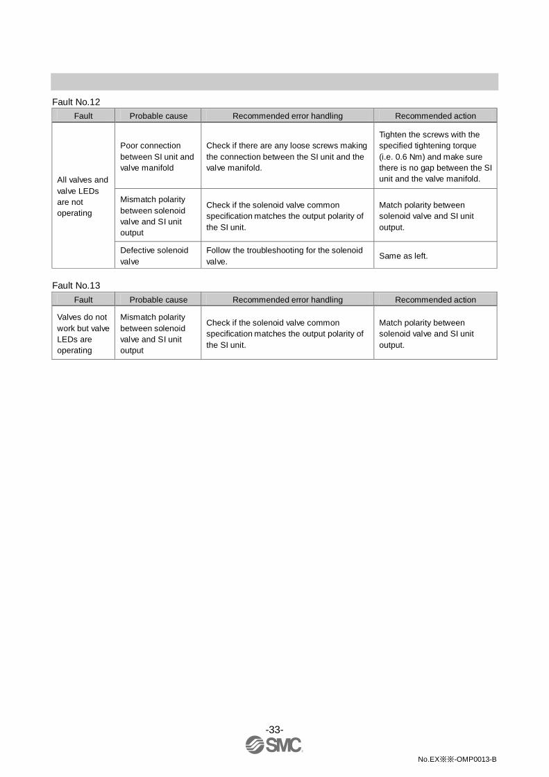
Fault No.12
Fault Probable cause Recommended error handling Recommended action
All valves and valve LEDs are not operating
Poor connection between SI unit and valve manifold
Check if there are any loose screws making the connection between the SI unit and the valve manifold.
Tighten the screws with the specified tightening torque (i.e. 0.6 Nm) and make sure there is no gap between the SI unit and the valve manifold.
Mismatch polarity between solenoid valve and SI unit output
Check if the solenoid valve common specification matches the output polarity of the SI unit.
Match polarity between solenoid valve and SI unit output.
Defective solenoid valve
Follow the troubleshooting for the solenoid valve.
Same as left.
Fault No.13
Fault Probable cause Recommended error handling Recommended action
Valves do not work but valve LEDs are operating
Mismatch polarity between solenoid valve and SI unit output
Check if the solenoid valve common specification matches the output polarity of the SI unit.
Match polarity between solenoid valve and SI unit output.

-34-
No.EX※※-OMP0013-B
○Maintenance Replacement of the SI unit •Remove the M3 hexagon screws from the SI unit and release the SI unit from the valve manifold. •Replace the SI unit. •Tighten the screws with the specified tightening torque. (0.6 Nm)
Precautions for maintenance (1) Be sure to switch off the power. (2) Check there is no foreign matter inside the SI unit. (3) Check there is no damage and no foreign matter on the gasket. (4) Be sure to tighten the screws with the specified torque.
If the SI unit is not assembled properly, inside PCBs may be damaged or liquid and/or dust may enter into the unit.
○Assembly and disassembly of the SI unit
-35-
No.EX※※-OMP0013-B
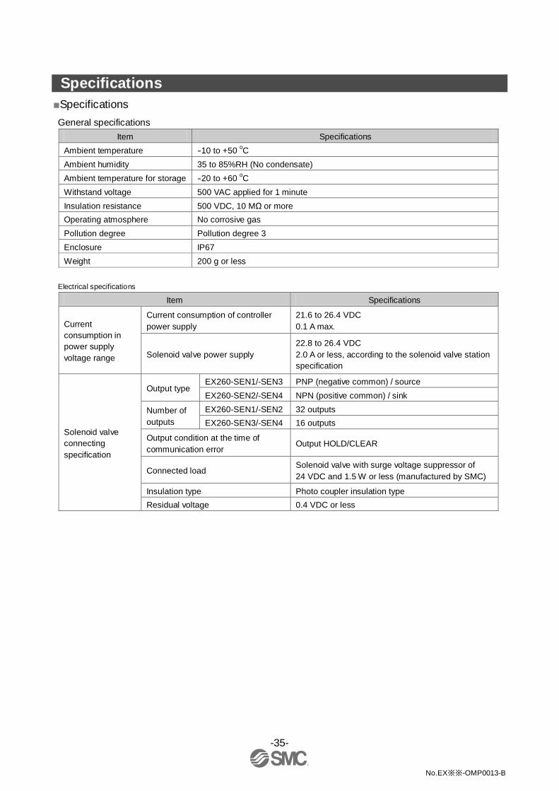
Specifications ■Specifications General specifications
Item Specifications Ambient temperature -10 to +50 oC Ambient humidity 35 to 85%RH (No condensate) Ambient temperature for storage -20 to +60 oC Withstand voltage 500 VAC applied for 1 minute Insulation resistance 500 VDC, 10 MΩ or more Operating atmosphere No corrosive gas Pollution degree Pollution degree 3 Enclosure IP67 Weight 200 g or less
Electrical specifications
Item Specifications
Current consumption in power supply voltage range
Current consumption of controller power supply
21.6 to 26.4 VDC 0.1 A max.
Solenoid valve power supply 22.8 to 26.4 VDC 2.0 A or less, according to the solenoid valve station specification
Solenoid valve connecting specification
Output type EX260-SEN1/-SEN3 PNP (negative common) / source EX260-SEN2/-SEN4 NPN (positive common) / sink
Number of outputs
EX260-SEN1/-SEN2 32 outputs EX260-SEN3/-SEN4 16 outputs
Output condition at the time of communication error
Output HOLD/CLEAR
Connected load Solenoid valve with surge voltage suppressor of 24 VDC and 1.5 W or less (manufactured by SMC)
Insulation type Photo coupler insulation type Residual voltage 0.4 VDC or less
-36-
No.EX※※-OMP0013-B
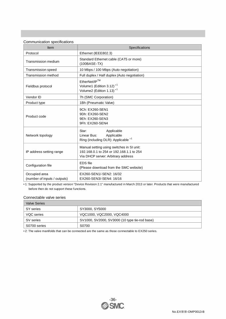
Communication specifications
Item Specifications Protocol Ethernet (IEEE802.3)
Transmission medium Standard Ethernet cable (CAT5 or more) (100BASE-TX)
Transmission speed 10 Mbps / 100 Mbps (Auto negotiation) Transmission method Full duplex / Half duplex (Auto negotiation)
Fieldbus protocol EtherNet/IPTM Volume1 (Edition 3.12) ∗1 Volume2 (Edition 1.13) ∗1
Vendor ID 7h (SMC Corporation) Product type 1Bh (Pneumatic Valve)
Product code
9Ch: EX260-SEN1 9Dh: EX260-SEN2 9Eh: EX260-SEN3 9Fh: EX260-SEN4
Network topology Star: Applicable Linear Bus: Applicable Ring (including DLR): Applicable ∗1
IP address setting range Manual setting using switches in SI unit: 192.168.0.1 to 254 or 192.168.1.1 to 254 Via DHCP server: Arbitrary address
Configuration file EDS file (Please download from the SMC website)
Occupied area (number of inputs / outputs)
EX260-SEN1/-SEN2: 16/32 EX260-SEN3/-SEN4: 16/16
∗1: Supported by the product version "Device Revision 2.1" manufactured in March 2013 or later. Products that were manufactured before then do not support these functions.
Connectable valve series
Valve Series SY series SY3000, SY5000 VQC series VQC1000, VQC2000, VQC4000 SV series SV1000, SV2000, SV3000 (10 type tie-rod base) S0700 series S0700
∗2: The valve manifolds that can be connected are the same as those connectable to EX250 series.

-37-
No.EX※※-OMP0013-B
○I/O Mapping Input area mapping
Offset (Word)
Input data MSB LSB MSB LSB 15 8 7 0
0 L L L L SOLV L L L L L L L L L L L L: Low fixed (0)
Input status area
Input status area specifications Item Status State
SOLV State of power supply for solenoid valve 0 Normal 1 Abnormal (19 V or less)
Output area mapping •For EX260-SEN1/-SEN2
Offset (Word)
Output data MSB LSB MSB LSB 15 8 7 0
0 15 14 13 12 11 10 9 8 7 6 5 4 3 2 1 0 1 31 30 29 28 27 26 25 24 23 22 21 20 19 18 17 16
•For EX260-SEN3/-SEN4
Offset (Word)
Output data MSB LSB MSB LSB 15 8 7 0
0 15 14 13 12 11 10 9 8 7 6 5 4 3 2 1 0

-38-
No.EX※※-OMP0013-B
■Dimensions
•If a fieldwireable connector is used for the power supply connection, and the SI unit is installed directly to a valve manifold, the connector should be φ16 mm or less. If the connector is a larger diameter it will interfere with the clamping face. Recommended cables are specified in the accessories section, on page 39.

-39-
No.EX※※-OMP0013-B
Accessories ○Connector cable
SI unit
connector Suitable connector
Description Part number Specifications Manufacturer
1 Fieldbus interface connector
Cable with communication connector
EX9-AC010EN-PSRJ: 1 m EX9-AC020EN-PSRJ: 2 m EX9-AC030EN-PSRJ: 3 m EX9-AC050EN-PSRJ: 5 m EX9-AC100EN-PSRJ: 10 m
Connector: M12 straight at one end and RJ45 at the other end
SMC
PCA-1446566 Connector: M12 straight Cable: 5 m
Fieldwireable connector
PCA-1446553 Connector: M12 straight
plug
2 Power supply connector
Cable with power supply connector
EX500-AP010-S Connector: M12 straight Cable: 1 m
EX500-AP050-S Connector: M12 straight Cable: 5 m
EX500-AP010-A Connector: M12 angle Cable: 1 m
EX500-AP050-A Connector: M12 angle Cable: 5 m
Cable with power supply connector (for SPEEDCON)
PCA-1401804 Connector: M12 straight Cable: 1.5 m
PCA-1401805 Connector: M12 straight Cable: 3 m
PCA-1401806 Connector: M12 straight Cable: 5 m
○Seal cap This cap is used to protect the M12 connector opening when the connector is not used. When the "BUS OUT" connector is not used, the seal cap can keep the SI unit under IP67 rated protection. (One seal cap will be attached to the SI unit when shipped from factory.)
Description Part No. Specification Seal cap EX9-AWTS For M12 connector socket: 10 pcs.

No.EX※※-OMP0013-B
Revision history A: Modified errors in text. B: Modified errors in text.
Note: Specifications are subject to change without prior notice and any obligation on the part of the manufacturer. EtherNet/IPTM is a trademark of ODVA. © 2012-2013 SMC Corporation All Rights Reserved