PRODUCT MODEL BASED DESIGN OF PRECAST FACADES …14705/FULLTEXT01.pdf · PRODUCT MODEL BASED DESIGN...
84
PRODUCT MODEL BASED DESIGN OF PRECAST FACADES Vesa Karhu Licentiate Thesis Division of Construction Management and Economics Department of Real Estate and Construction Management Royal Institute of Technology Stockholm, Sweden 1997
Transcript of PRODUCT MODEL BASED DESIGN OF PRECAST FACADES …14705/FULLTEXT01.pdf · PRODUCT MODEL BASED DESIGN...

PRODUCT MODEL BASED DESIGNOF
PRECAST FACADES
Vesa Karhu
Licentiate ThesisDivision of Construction Management and EconomicsDepartment of Real Estate and Construction ManagementRoyal Institute of TechnologyStockholm, Sweden1997

2

3
PREFACEThe research presented in this thesis has been conducted at VTT BuildingTechnology and the Royal Institute of Technology (KTH) between 1992and 1997. KTH is for the moment the leading institute in product modellingresearch in the Scandinavian countries.
I would like to thank my supervisor Prof. Bo-Christer Björk for encouragingme to continue the work. I would also like to thank Mr. Matti Hannus forinitialising the research and for valuable comments during the initial phasesof the work.
This research was funded by the Technical Research Centre of Finland(VTT), The Finnish Association of Construction Products Industries (RTT)and the Technology Development Centre of Finland (TEKES). Thecompanies that participated in the testing were the architectural companyArkkitehtitoimisto Innovarch Oy, the structural engineering companyTampereen Juva Oy and the manufacturer Partek Betonila Oy. The finalarchitectural software was developed in Studio Kivi Oy. I would like tothank the persons from the above companies.
Additionally I would like to thank Prof. Brian Atkin for the Englishlanguage aspects, Associate Prof. Jan Bröchner for valuable comments andsuggestions. I would also like to thank my colleagues at VTT BuildingTechnology and KTH for their valuable comments and suggestions.
An important factor during the research has been my kayaking hobby. Hardtraining is balanced by hard work. Special thanks go to my common-lawwife Katarina who has given me support during the last phases of theresearch.
Espoo, May 1997.
Vesa Karhu

4

5
ABSTRACTIn Finland, approximately 80 % of the facades of buildings aremanufactured as precast units. Currently one of the obstacles to making theoverall design and construction of precast building facades more efficient isthe inefficient exchange of data about facades between architects, structuralengineers and precast element manufacturers. The product model approachseems to offer a new methodology for data exchange and sharing whichwould solve many of the current problems. This thesis presents the resultsof research in which this approach was tested.
The prevailing way of designing facades was chosen as a reference processmodel. Based on an analysis of data needs in the different stages of theprocess a product data model of a facade was developed. The product datamodel was restricted to facades only and does not include other informationabout the building. Central data structures in the conceptual schema definehow a precast concrete facade consists of precast concrete units, i.e.,elements. Structural wall layers that may have openings form the elements.
The conceptual schema was implemented as a prototype which was basedon existing software, modified and further developed. The prototype wastested by an architectural design company, a structural design company anda manufacturer. The main conclusion of testing was that the data producedin the architectural design is directly usable in further design. The structuralor element design may use the architectural data as such. Also, it is possibleto create applications that take into account the architect's preferred designapproach.
KEYWORDS: facade, precast concrete, data exchange, object oriented,architectural design

6

7
SAMMANFATTNINGI Finland tillverkas ungefär 80 % av alla fasader av prefabricerade element.För närvarande är ett av hindren för att effektivisera projekteringen ochbyggandet av prefabricerade fasader den ineffektiva dataöverföringenmellan arkitekter, konstruktörer och elementtillverkare. Produktmodelleringverkar att erbjuda en ny metodik för dataöverföring och -distribution, somkunde lösa många av dagens problem. Denna avhandling presenterarresultat från ett forskningsprojekt där en dylik metodik har testats.
Det idag dominerande sättet att projektera fasader valdes som enutgångspunkt (processmodell) i studien. På basen av en analys avinformationsbehovet i processens olika skeden definierades enproduktmodell som strukturerar informationen om en fasad. Modellenbegränsades till enbart fasaden och inkluderar därmed inte annaninformation om byggnaden ifråga. Centrala datastrukturer i begreppschematbeskriver hur en prefabricerad betongfasad består av prefabricerade enheter,dvs. element. Elementen består av vägglager som kan innehålla öppningar.
Begreppschemat implementerades i en prototyp, baserad på existerandeprogramvara, vilken modifierades och utvecklades vidare. Prototypentestades av en arkitektbyrå, en konstruktör och en tillverkare avbetongelement. Huvudslutsatsen av testningen var att den information somproduceras i arkitektprojekteringen direkt är användbar i den fortsattaprojekteringen. Det är också möjligt att utveckla IT-tillämpningar som tarhänsyn till arkitekternas preferenser beträffande arbetssätt.
NYCKEORD: Fasad, prefabricerad betong, dataöverföring,objektorienterad, arkkitektprojektering

8

9
CONTENTSPREFACE...................................................................................................... 3
ABSTRACT .................................................................................................. 5
SAMMANFATTNING ................................................................................. 7
CONTENTS .................................................................................................. 9
LIST OF ABBREVIATIONS ..................................................................... 11
1. INTRODUCTION................................................................................... 13
1.1 Background........................................................................................ 13
1.2 Research questions............................................................................. 14
1.3 Scope and phases of the research....................................................... 15
1.4 Structure of the thesis ........................................................................ 16
2. RELATED RESEARCH ......................................................................... 19
2.1 Methods for integration ..................................................................... 19
2.2 Product data model vs. product model............................................... 20
2.3 STEP standardisation......................................................................... 21
2.4 Generic building product model proposals ........................................ 22
2.5 Aspect models.................................................................................... 24
3. METHODOLOGY .................................................................................. 27
3.1 Methods used in this research............................................................ 27
3.2 Choice of modelling tools.................................................................. 27
3.3 Object definition cards....................................................................... 29
3.4 Kinds of evidence .............................................................................. 30
4. THE BUILDING DESIGN PROCESS................................................... 31
4.1 Level of prefabrication in Finland ..................................................... 31
4.2 The overall design process................................................................. 31
4.3 The detailed design stage design........................................................ 34
4.4 Analysis of current problems ............................................................. 36
5. THE PRODUCT DATA MODEL OF A FACADE ............................... 39
5.1 Modelling procedure.......................................................................... 39
5.2 The decomposition hierarchy of facade............................................. 41
5.3 Structural layer................................................................................... 42
5.4 Opening.............................................................................................. 43

10
5.5 Edge ................................................................................................... 44
5.6 Surface ............................................................................................... 45
5.7 Overall model..................................................................................... 46
6. CHECK LISTS........................................................................................ 49
6.1 Formulation of the check lists............................................................ 49
6.2 Possible uses of the check lists .......................................................... 51
7. DEVELOPING PROTOTYPE SOFTWARE ......................................... 53
7.1 Implementation of type objects.......................................................... 53
7.2 Functions of the prototype ................................................................. 54
7.3 The final prototype............................................................................. 56
8. TESTING THE DEVELOPED METHODS IN PRACTICE ................. 57
8.1 Purpose of the testing......................................................................... 57
8.2 Test building ...................................................................................... 57
8.3 Software ............................................................................................. 58
8.4 Prototype software test....................................................................... 58
8.5 Test design ......................................................................................... 59
8.6 Results................................................................................................ 62
8.7 Limitations and restrictions of the model .......................................... 62
9. CONCLUSIONS ..................................................................................... 65
9.1 Usefulness of the results .................................................................... 65
9.2 A possible way ahead - STEP and IFC.............................................. 66
ACKNOWLEDGEMENTS......................................................................... 67
REFERENCES............................................................................................ 69
APPENDIX A: SADT/IDEF0 syntax.......................................................... 73
APPENDIX B: EXPRESS language ........................................................... 75
APPENDIX C: Schema of the facade in EXPRESS................................... 77
11
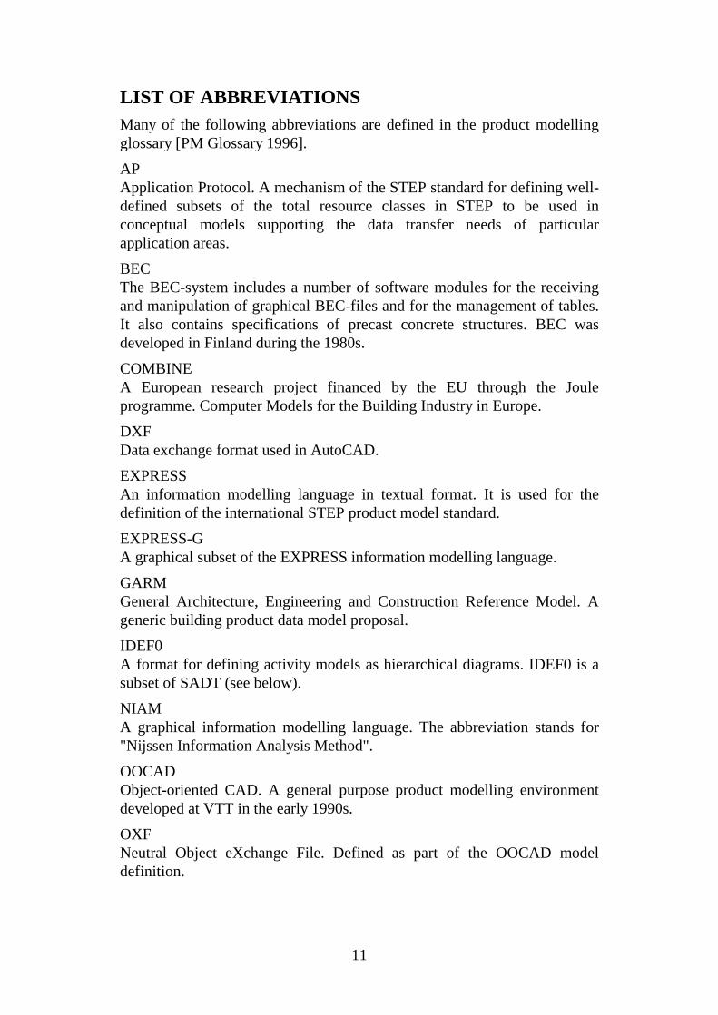
LIST OF ABBREVIATIONSMany of the following abbreviations are defined in the product modellingglossary [PM Glossary 1996].
APApplication Protocol. A mechanism of the STEP standard for defining well-defined subsets of the total resource classes in STEP to be used inconceptual models supporting the data transfer needs of particularapplication areas.
BECThe BEC-system includes a number of software modules for the receivingand manipulation of graphical BEC-files and for the management of tables.It also contains specifications of precast concrete structures. BEC wasdeveloped in Finland during the 1980s.
COMBINEA European research project financed by the EU through the Jouleprogramme. Computer Models for the Building Industry in Europe.
DXFData exchange format used in AutoCAD.
EXPRESSAn information modelling language in textual format. It is used for thedefinition of the international STEP product model standard.
EXPRESS-GA graphical subset of the EXPRESS information modelling language.
GARMGeneral Architecture, Engineering and Construction Reference Model. Ageneric building product data model proposal.
IDEF0A format for defining activity models as hierarchical diagrams. IDEF0 is asubset of SADT (see below).
NIAMA graphical information modelling language. The abbreviation stands for"Nijssen Information Analysis Method".
OOCADObject-oriented CAD. A general purpose product modelling environmentdeveloped at VTT in the early 1990s.
OXFNeutral Object eXchange File. Defined as part of the OOCAD modeldefinition.

12
RATASComputer-aided design of buildings. An abbreviation for research,development and standardisation projects in Finland. RATAS-work isformally organised by a committee under the Building Information Institute.
SADTA format for defining activity models as hierarchical diagrams (see alsoIDEF0 above). The abbreviation stands for Structured Analysis DesignTechnique.
STEPStandard for the Exchange of Product Model Data.
13
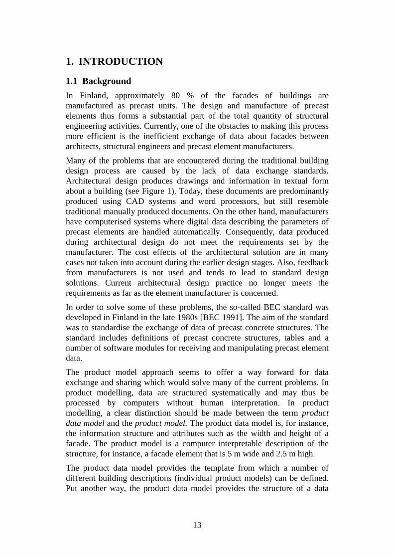
1. INTRODUCTION
1.1 Background
In Finland, approximately 80 % of the facades of buildings aremanufactured as precast units. The design and manufacture of precastelements thus forms a substantial part of the total quantity of structuralengineering activities. Currently, one of the obstacles to making this processmore efficient is the inefficient exchange of data about facades betweenarchitects, structural engineers and precast element manufacturers.
Many of the problems that are encountered during the traditional buildingdesign process are caused by the lack of data exchange standards.Architectural design produces drawings and information in textual formabout a building (see Figure 1). Today, these documents are predominantlyproduced using CAD systems and word processors, but still resembletraditional manually produced documents. On the other hand, manufacturershave computerised systems where digital data describing the parameters ofprecast elements are handled automatically. Consequently, data producedduring architectural design do not meet the requirements set by themanufacturer. The cost effects of the architectural solution are in manycases not taken into account during the earlier design stages. Also, feedbackfrom manufacturers is not used and tends to lead to standard designsolutions. Current architectural design practice no longer meets therequirements as far as the element manufacturer is concerned.
In order to solve some of these problems, the so-called BEC standard wasdeveloped in Finland in the late 1980s [BEC 1991]. The aim of the standardwas to standardise the exchange of data of precast concrete structures. Thestandard includes definitions of precast concrete structures, tables and anumber of software modules for receiving and manipulating precast elementdata.
The product model approach seems to offer a way forward for dataexchange and sharing which would solve many of the current problems. Inproduct modelling, data are structured systematically and may thus beprocessed by computers without human interpretation. In productmodelling, a clear distinction should be made between the term productdata model and the product model. The product data model is, for instance,the information structure and attributes such as the width and height of afacade. The product model is a computer interpretable description of thestructure, for instance, a facade element that is 5 m wide and 2.5 m high.
The product data model provides the template from which a number ofdifferent building descriptions (individual product models) can be defined.Put another way, the product data model provides the structure of a data

14
base system which can be filled with information about individualbuildings.
Research covering product modelling has been undertaken in manycountries, but the models presented have been somewhat theoretical.Testing of the models has generally been limited and, thus, they cannot beimplemented directly.
Structuraldesign
Manufacturing
Structureddata
Drawings andtextual data
Scale 1:50Scale 1:50
Scale 1:50
Architecturaldesign
Figure 1. Current situation of data exchange in Finland. Data fromarchitectural design is transferred to structural design as drawings andtextual data. Manufacturers may receive structured data, for instance, inBEC-format [BEC 1991].
1.2 Research questions
The integration of the design of a precast facade is of considerableimportance to improving the overall efficiency of the building process.Traditional architectural design is not sufficiently efficient to enablecomplete integration. The questions that arise are:
• what kind of approach should be used to integrate the architecturaldesign of precast facades with the design and manufacture of elements?
• how can the effects of this integration be verified and evaluated againstthe traditional design procedure?
Architectural design tends to concentrate on visible objects such as surfacesand edges of windows or door openings. Thus, the first schematic designsdo not contain much data on concrete for use in element design ormanufacture. Accordingly, the affected designs must be completed by thestructural engineer. The various parties involved in a building design projecthave different ideas, concepts, information and computer applicationsconcerning what shall be designed and manufactured. Further questionsarise:

15
• what are the characteristic features of the traditional architectural designprocess?
• what kind of standardisation is needed to achieve integration?
The question about the features of the design process is interesting whencompared to the integration requirements. Shall a process in itself remainthe same or should the process be re-engineered? However, this questionfalls outside the scope of this research and is not, therefore, developedfurther.
1.3 Scope and phases of the research
The scope of the research presented in this thesis was the integration of thearchitectural design process of facades with the manufacturing process, bydefining a product data model of a precast concrete facade. Also, the scopeincluded the formalisation of the results into guidelines and instructions.
The primary focus was on data exchange, from the architectural design tothe element design and manufacturing, during the tendering phase and theinitial phase of the element design.
The key phases of the research were as follows.
• Define a basic activity model of the building design process of precastconcrete facades emphasising architectural design.
• Analyse the problems occurring in the current design process.
• Define a product data model of a precast concrete facade.
• Define check-lists of the data input and output requirements.
• Develop prototype software based on the product data model.
• Test the prototypes with data from a real project.
• Conclude if a product model based architectural design process enhancesthe whole building design process.
• Propose guidelines for using the product model based approach in thearchitectural design of facades.
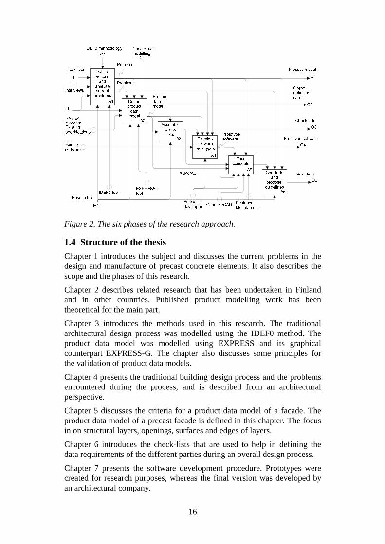
The research approach, comprising its six phases, is shown in Figure 2. Thefigure uses the SADT notation (see Appendix A for more details on SADTmethod). The software developer and other parties in the project had a roleduring the development of software prototypes and testing. These can beseen as mechanisms to the activities A4 and A5. All other activities wereperformed by the author.
16
O1
Process model
I2
Interviews
O2
Objectdefinitioncards
I3
Relatedresearch
O3
Check lists
O4
Prototype software
O5
Guidelines
C1
ConceptualmodellingC2
IDEF0 methodology
Defineprocessand
analysecurrentproblems
A1 Defineproductdatamodel
A2Assemblechecklists
A3 Developsoftwareprototypes
A4Test
concepts
A5Conclude
andproposeguidelines
A6
Process
Problems
Productdatamodel
Prototypesoftware
I1
Task lists
Existingsoftware
Existingspecifications
Softwaredeveloper
Designer,Manufacturer
M1
Researcher
IDEF0-toolEXPRESS-tool
AutoCAD
ConcreteCAD
Figure 2. The six phases of the research approach.
1.4 Structure of the thesis
Chapter 1 introduces the subject and discusses the current problems in thedesign and manufacture of precast concrete elements. It also describes thescope and the phases of this research.
Chapter 2 describes related research that has been undertaken in Finlandand in other countries. Published product modelling work has beentheoretical for the main part.
Chapter 3 introduces the methods used in this research. The traditionalarchitectural design process was modelled using the IDEF0 method. Theproduct data model was modelled using EXPRESS and its graphicalcounterpart EXPRESS-G. The chapter also discusses some principles forthe validation of product data models.
Chapter 4 presents the traditional building design process and the problemsencountered during the process, and is described from an architecturalperspective.
Chapter 5 discusses the criteria for a product data model of a facade. Theproduct data model of a precast facade is defined in this chapter. The focusin on structural layers, openings, surfaces and edges of layers.
Chapter 6 introduces the check-lists that are used to help in defining thedata requirements of the different parties during an overall design process.
Chapter 7 presents the software development procedure. Prototypes werecreated for research purposes, whereas the final version was developed byan architectural company.

17
Chapter 8 presents the test design process and the results. The test wasbased on the traditional building design process, but with a product modelapproach. A number of ideas and limitations are also discussed.
In Chapter 9 conclusions are presented. The traditional architectural designprocess may use the product model approach as this provides more accuratedata definitions.
Appendix A presents a summary the function modelling techniques SADTand IDEF0. Selected examples are provided.
Appendix B presents a short introduction to the EXPRESS language and itsgraphical counterpart EXPRESS-G. The EXPRESS language is used inSTEP technology.
Appendix C presents the full schema of the facade in textual format.
A shorter version of this thesis has been published in the Electronic Journalof Information Technology in Construction [Karhu 1997].

18

19
2. RELATED RESEARCH
2.1 Methods for integration
Luiten [1994] recognises six ways in which communication betweencomputer applications may be accomplished:
• closed integrated systems;
• open integrated systems;
• communication with low semantic representations;
• classification and coding;
• product modelling; and
• knowledge-based technologies.
Closed integrated systems are vendor specific systems covering manyapplications. Some early examples of building design systems are thosedeveloped in the UK in the 1970s [Jones 1982]. Open systems, on the otherhand, allow communication with other programs, but they use an internaldata exchange. Low semantic representations are usually limited to, forinstance, descriptions of the geometry. An example is the DXF format.Classification or coding provides a method for communication on a higherlevel. An example is the SfB classification for project information [CIB1977] that comprises functional building elements, activities and resources.Product modelling provides a means for communicating on a higher level.Knowledge based systems concentrate on the formalisation of both data andknowledge.
During the 1970s and early 1980s, CAD systems became popular and wereconsidered to be the primary vehicle for integration. CAD systems usedgeometrical information based on a number of different modelling methods(wire models, surface models, etc.). The geometry cannot be used as theonly means of integration because [Luiten 1994]:
• the shape of the product is not stable during the design process;
• information exists before the shape is chosen; and
• parties in a project use different shape representations.
Since the early 1980s other integration techniques used in CAD systemsinclude layering [Björk et al. 1996] and reference file techniques. Thesesystems concentrate on splitting up an overall building model according tobuilding elements and responsibility for their inherent information, as wellas facilitating views of the models and supporting the plotting of drawings.

20
2.2 Product data model vs. product model
During the late 1980s, the concepts of geometric modelling evolved intoproduct modelling. The product model approach seems to offer the toolsneeded to overcome some of the persistent problems in data exchange.
In a product model, data about an artefact are arranged in a systematic wayusing object oriented data base principles. Traditional CAD softwareprimarily models the graphical appearance of the building parts. Theproduct model approach describes building parts directly. This approach hasbeen a prime research subject for some ten years. It is currently receivingincreasing attention both in standardisation efforts, such the ISO STEPprocess [ISO 1994b] and the Industry Foundation Classes initiative [IAI1996] as well as in the development of commercial software.
A central concept in the following presentation is the conceptual schema. Inthe theory of conceptual modelling or data base design the conceptualschema denotes the formalised description of the structure of theinformation stored in an information base [Boman et al. 1991], [ISO 1985].Conceptual schemata may be used to structure database applications asdiverse as census records, banking applications, missile guidance systems ordescriptions of aircraft.
A product data model is defined as [PM Glossary 1996]: A particular typeof conceptual schema, which structures the information needed to describe aphysical artefact, designed and manufactured by man. The central objectclasses of product data models describe the functional parts of the artefactand assemblies formed by them, rather than concepts needed forrepresenting the parts in different kinds of documents.
A product model is a computer-interpretable description of an artefact,structured according to some predefined product data model.
Figure 3 illustrates the difference between a conceptual schema and aninformation base. It also provides an example of two differentimplementations of the same information base using a data base and theSTEP physical file format [ISO 1994] which is presently used for productdata exchange. The information base presented in the figure contains theactual values of a real designed object such as the facade and its position (x-coordinate, y-coordinate, etc.), shape, a unique id, etc..
In the literature and in practice, the term product model is often used todescribe the conceptual schema even though the term product data modelwould be more correct. For a general discussion of product models andproduct data models see Björk [1995].

21
FACADEFacade_1Facade_2...
Textual
SCHEM A Exam ple;ENTITY facade SUPERTYPE OF (precast_facade ANDOR cast_in_situ_facade);id : id ;position: pos ition ;shape : shape ;balconies: O PTIONAL SET [1:?] OF balcony ;channels : O PTIONAL SET [1 :?] OF channel ;END_ENTITY ;ENTITY pos itionid : id ;x_coord,y_coord,z_coord : REAL;x_rot,y_rot,z_rot: REAL;END_ENTITY:ENTITY shapeid: id ;END_ENTITY;...
END_SCHEM A;
Physical file
ISO -10303-21 ;H E A D E R ;F ILE _D E SC R IP TIO N (E xam ple V K K );F ILE _S C E H M A('E xam ple ');E N D S E C ;D A T A ;#1 =F AC A D E ('Facad e_ 1',# 3 ,#5 ,$ ,$);#2 =F AC A D E ('Facad e_ 2',# 4 ,#6 ,$ ,$);#3=PO SIT IO N ('Po sition_1 ',0 .0,0.0 ,0 .0,0 .0 ,0 .0 ,0.0 );#4=PO SIT IO N ('P osition_2 ',5 000 .0 ,0 .0 ,0 .0,0 .0 ,0 .0,0 .0 );#5 =S H A P E ('S ha pe_ 1',......E N D S E C ;E N D -IS O -10303-2 1 ;
position
id
shape
balconies S [1:?]
channe ls S [1:? ]
cast_ in_situ_facade
facade
precast_facade
shape
balcony
channel
id
position
Graphical
Information base
Data base
Conceptual schema
POSITIONPosition_1Position_2
SHAPEShape_1Shape_2
Figure 3. An example of a part of a small conceptual schema in textualformat (upper left corner) and graphical presentation (upper right). Theinformation base is presented in the lower left corner as a data base and asa STEP physical file in the lower right corner.
2.3 STEP standardisation
The STEP standardisation effort in product modelling is important bothfrom the industry viewpoint, but also because it has provided a lot ofimpetus for research in the domain. The acronym STEP stands forStandardisation for the Exchange of Product model data. It is organisedunder the International Organisation for Standardisation (ISO). Thestandard currently contains 12 parts.
22
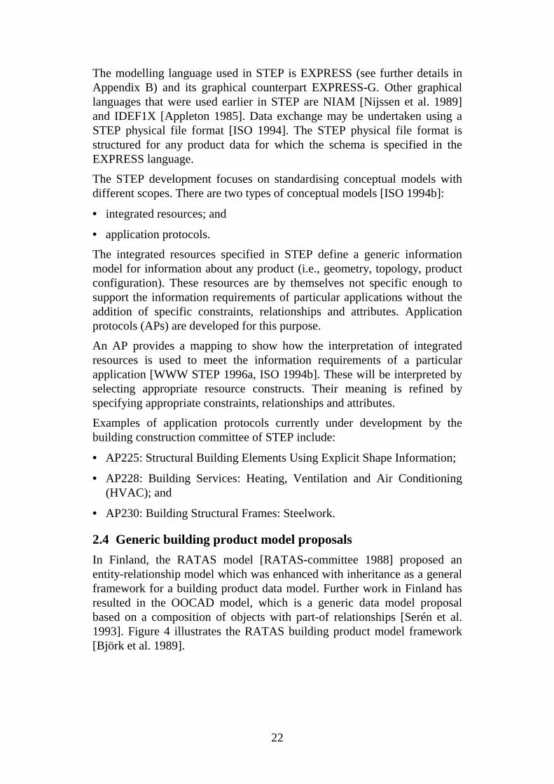
The modelling language used in STEP is EXPRESS (see further details inAppendix B) and its graphical counterpart EXPRESS-G. Other graphicallanguages that were used earlier in STEP are NIAM [Nijssen et al. 1989]and IDEF1X [Appleton 1985]. Data exchange may be undertaken using aSTEP physical file format [ISO 1994]. The STEP physical file format isstructured for any product data for which the schema is specified in theEXPRESS language.
The STEP development focuses on standardising conceptual models withdifferent scopes. There are two types of conceptual models [ISO 1994b]:
• integrated resources; and
• application protocols.
The integrated resources specified in STEP define a generic informationmodel for information about any product (i.e., geometry, topology, productconfiguration). These resources are by themselves not specific enough tosupport the information requirements of particular applications without theaddition of specific constraints, relationships and attributes. Applicationprotocols (APs) are developed for this purpose.
An AP provides a mapping to show how the interpretation of integratedresources is used to meet the information requirements of a particularapplication [WWW STEP 1996a, ISO 1994b]. These will be interpreted byselecting appropriate resource constructs. Their meaning is refined byspecifying appropriate constraints, relationships and attributes.
Examples of application protocols currently under development by thebuilding construction committee of STEP include:
• AP225: Structural Building Elements Using Explicit Shape Information;
• AP228: Building Services: Heating, Ventilation and Air Conditioning(HVAC); and
• AP230: Building Structural Frames: Steelwork.
2.4 Generic building product model proposals
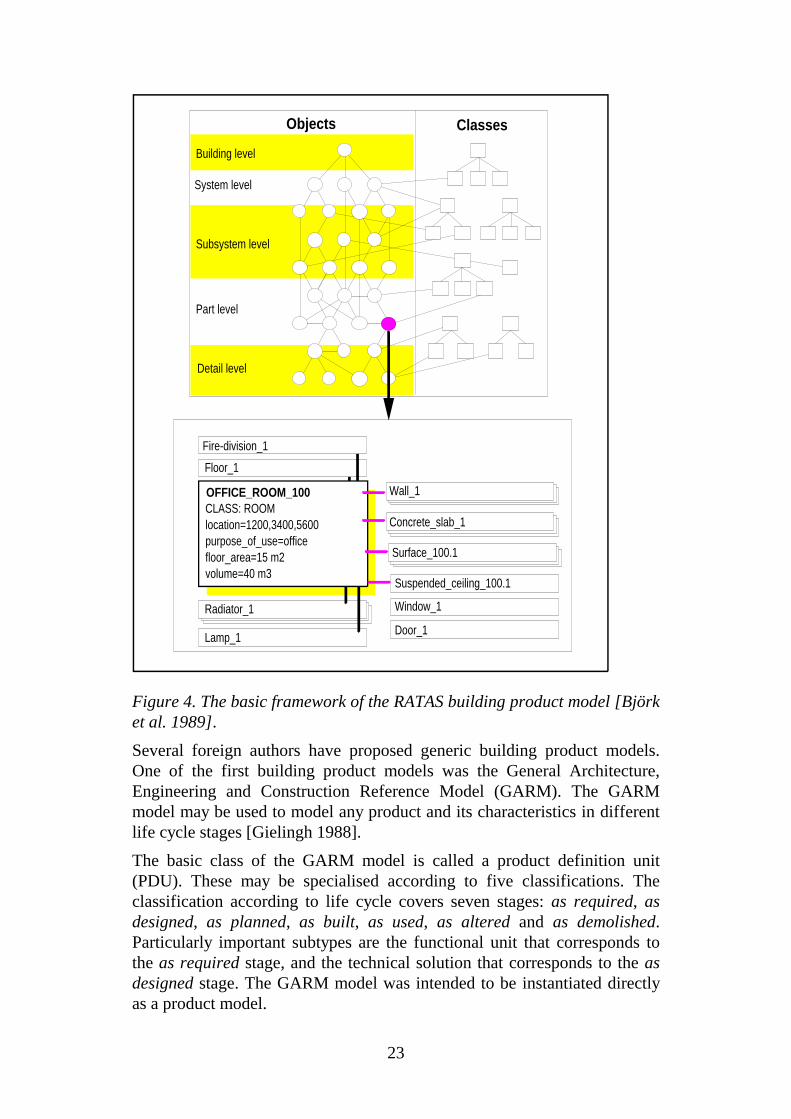
In Finland, the RATAS model [RATAS-committee 1988] proposed anentity-relationship model which was enhanced with inheritance as a generalframework for a building product data model. Further work in Finland hasresulted in the OOCAD model, which is a generic data model proposalbased on a composition of objects with part-of relationships [Serén et al.1993]. Figure 4 illustrates the RATAS building product model framework[Björk et al. 1989].
23
Objects Classes
Building level
System level
Subsystem level
Part level
Detail level
Fire-division_1
Floor_1
Wall_1
Surface_100.1
Concrete_slab_1
Radiator_1
Lamp_1
CLASS: ROOMlocation=1200,3400,5600purpose_of_use=officefloor_area=15 m2volume=40 m3
OFFICE_ROOM_100
Suspended_ceiling_100.1
Window_1
Door_1
Figure 4. The basic framework of the RATAS building product model [Björket al. 1989].
Several foreign authors have proposed generic building product models.One of the first building product models was the General Architecture,Engineering and Construction Reference Model (GARM). The GARMmodel may be used to model any product and its characteristics in differentlife cycle stages [Gielingh 1988].
The basic class of the GARM model is called a product definition unit(PDU). These may be specialised according to five classifications. Theclassification according to life cycle covers seven stages: as required, asdesigned, as planned, as built, as used, as altered and as demolished.Particularly important subtypes are the functional unit that corresponds tothe as required stage, and the technical solution that corresponds to the asdesigned stage. The GARM model was intended to be instantiated directlyas a product model.
24
The GARM model has been further developed in the IMPPACT referencemodel [Gielingh et al. 1993] which uses conceptual models of differentscopes. The IMPPACT model tries to combine both process modelling andproduct modelling. The process modelling concentrates on production.
The AEC Building Systems Model is focused on the functional systems ofwhich a building is composed [Turner 1990]. The functional systems are,for example, enclosure, structural and mechanical systems. It differs fromthe GARM model in that its analysis is oriented to the functions of buildingparts rather that to more generic classifications.
2.5 Aspect models
Recently, there has been a shift from all-encompassing product models toconceptual schemas describing more limited domains. Terms such as aspectmodels have been used to describe such types. A good example of an aspectmodel is the Integrated Data Model (IDM) provided by the COMBINEproject [Dubois et al. 1992]. The IDM model concentrates on buildingenergy and HVAC system information. An example of an entity in the IDMmodel [COMBINE 1995] is the wall that is defined as:
ENTITY wallSUBTYPE OF (elementary_space_enclosing_element);loadability : load_bearing ;has_wall_type: OPTIONAL wall_type ;
END_ENTITY ;
The loading attribute receives a Boolean value. The wall type is defined asTYPE wall_type = ENUMERATION OF ( framed, non_framed);END_TYPE;
The wall has also a construction type which may be composed by layers.
For the particular field of structural design, some models have beenproposed. Hannus [1990] discusses CAD systems based on productmodelling for precast concrete structures. The main topics are theinterchange of data between CAD systems, product modelling andimplementation.
Dale [1991] uses object oriented modelling techniques for structural design.He also uses GARM as a reference model. He mentions the multiplerepresentations of the structural design. The different models are ageometric model, structural model and a computational model. Dale’smodel has been tested using a plate girder bridge model.
Lavakare uses the product model approach for a structural steel framingdata model [Lavakare et al. 1989]. His model is divided into eighthierarchical levels where the entity building is on the highest level.
Karlshøy [1994] presents a construction information model KONIM whichis a building product model. It is based on the principle of references, where
25
only a minor part of the building information is stored in the core of theproduct model. The remaining information is stored in the references.
Luiten [1994] used precast concrete structures to test product models ofbeams, columns, hollow core slabs and connections. The goal in hisresearch was to develop a strategy to support integration of design andconstruction in building projects. He proposes a building project model(BPM) that integrates product, activity and resource information.
CIMSTEEL [Watson 1995] uses the product model approach for structuralsteel framing data models. Based on this work, a STEP application protocol(AP 230: Building structural frames: Steelwork) is under development forthis area.
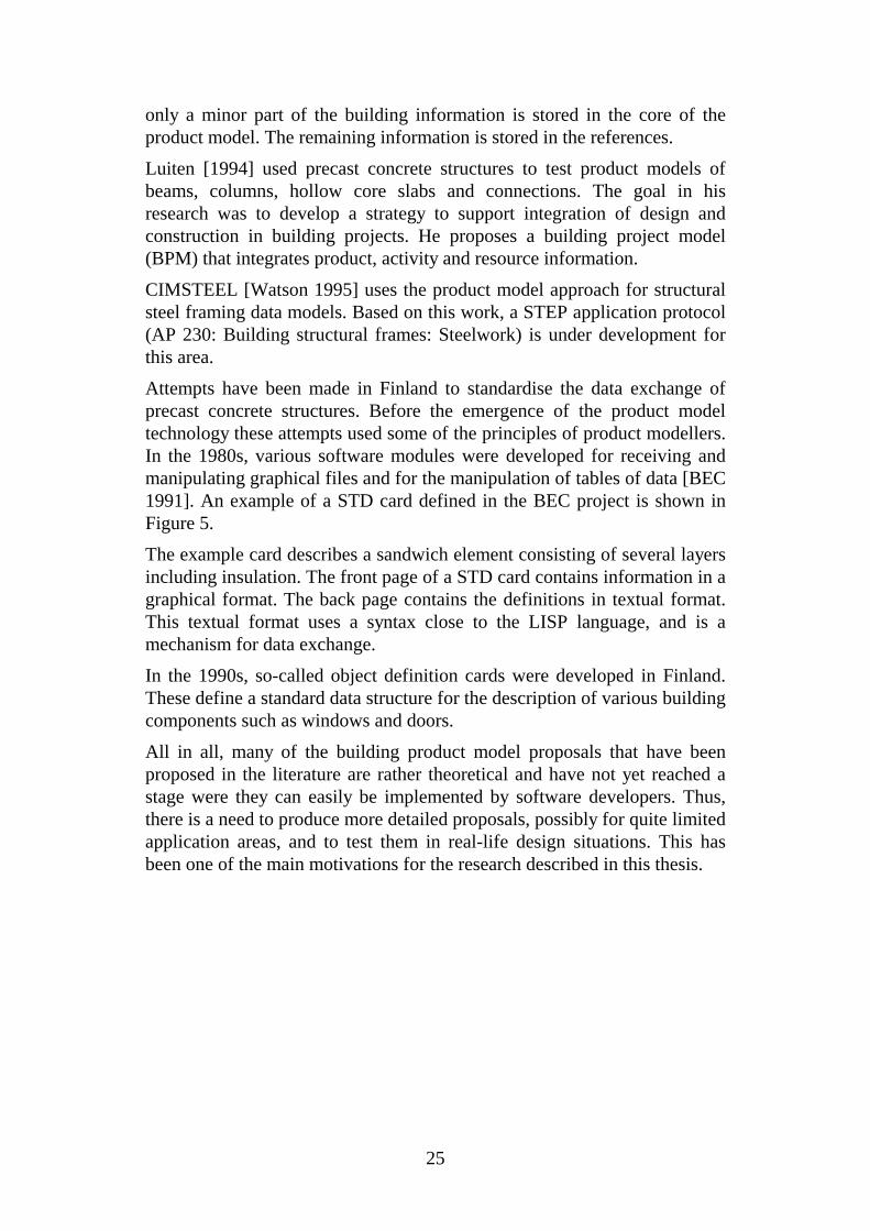
Attempts have been made in Finland to standardise the data exchange ofprecast concrete structures. Before the emergence of the product modeltechnology these attempts used some of the principles of product modellers.In the 1980s, various software modules were developed for receiving andmanipulating graphical files and for the manipulation of tables of data [BEC1991]. An example of a STD card defined in the BEC project is shown inFigure 5.
The example card describes a sandwich element consisting of several layersincluding insulation. The front page of a STD card contains information in agraphical format. The back page contains the definitions in textual format.This textual format uses a syntax close to the LISP language, and is amechanism for data exchange.
In the 1990s, so-called object definition cards were developed in Finland.These define a standard data structure for the description of various buildingcomponents such as windows and doors.
All in all, many of the building product model proposals that have beenproposed in the literature are rather theoretical and have not yet reached astage were they can easily be implemented by software developers. Thus,there is a need to produce more detailed proposals, possibly for quite limitedapplication areas, and to test them in real-life design situations. This hasbeen one of the main motivations for the research described in this thesis.

26
Z
Yo
b1+b2+b3+b4
Yo
e1(x,y,z)s1(x,y,z)
X
Dimensions:u1=[dx(max),0,dz(max)]u2=[L(x),0,0]u3=[0,B(y),0]u4=[0,0,H(z)]
X
Z
X
Y
Y
Z
ELEMENT CARD
SANDWICH ELEMENT
4.2.10
15.04.91
1
2.0
Class:
Element:
No:
Date:
Page:
Rev:
ELEMENT CARD
SANDWICH ELEMENT
4.2.10
15.04.91
2
2.0
Class:
Element:
No:
Date:
Page:
Rev:
(OBJ objid(DES 'Sandwich element')(POS x y z ux uy uz vx vy vz)(CLA sandwich(MAX L B H)(LBH L B H)(CODE name ...)...)(CLA concrete...)
)
Figure 5. An example of a STD card defined in the BEC-standard [BEC1991]. The front page and a portion of the back page are shown.
27
3. METHODOLOGY
3.1 Methods used in this research
In this research the following general methods were adopted.
• Gather basic information and data in interviews with clients, architects,structural engineers, contractors, manufacturers and software developers.
• Use formal process modelling methods for activity modelling.
• Use formal conceptual modelling methods for product modelling.
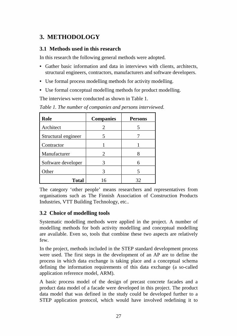
The interviews were conducted as shown in Table 1.
Table 1. The number of companies and persons interviewed.
Role Companies Persons
Architect 2 5
Structural engineer 5 7
Contractor 1 1
Manufacturer 2 8
Software developer 3 6
Other 3 5
Total 16 32
The category ‘other people’ means researchers and representatives fromorganisations such as The Finnish Association of Construction ProductsIndustries, VTT Building Technology, etc..
3.2 Choice of modelling tools
Systematic modelling methods were applied in the project. A number ofmodelling methods for both activity modelling and conceptual modellingare available. Even so, tools that combine these two aspects are relativelyfew.
In the project, methods included in the STEP standard development processwere used. The first steps in the development of an AP are to define theprocess in which data exchange is taking place and a conceptual schemadefining the information requirements of this data exchange (a so-calledapplication reference model, ARM).
A basic process model of the design of precast concrete facades and aproduct data model of a facade were developed in this project. The productdata model that was defined in the study could be developed further to aSTEP application protocol, which would have involved redefining it to
28
reuse the data structures of STEP resource entity definitions. However, thiswas deemed to be outside the scope of the research because limitedresources were available. The development of an AP would requireinternational co-operation and a contribution of about 3-4 years of work.
The building design process from briefing to construction and finalapproval was modelled using SADT-charts [Marca et al. 1987]. Specialinterest was focused on tasks that are of importance in architectural design.
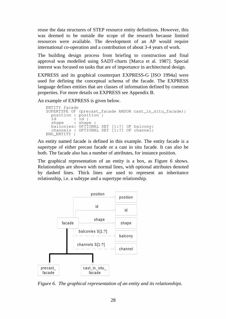
EXPRESS and its graphical counterpart EXPRESS-G [ISO 1994a] wereused for defining the conceptual schema of the facade. The EXPRESSlanguage defines entities that are classes of information defined by commonproperties. For more details on EXPRESS see Appendix B.
An example of EXPRESS is given below.ENTITY facadeSUPERTYPE OF (precast_facade ANDOR cast_in_situ_facade);
position : position ;id : id ;shape : shape ;balconies: OPTIONAL SET [1:?] OF balcony;channels : OPTIONAL SET [1:?] OF channel;
END_ENTITY ;
An entity named facade is defined in this example. The entity facade is asupertype of either precast facade or a cast in situ facade. It can also beboth. The facade also has a number of attributes, for instance position.
The graphical representation of an entity is a box, as Figure 6 shows.Relationships are shown with normal lines, with optional attributes denotedby dashed lines. Thick lines are used to represent an inheritancerelationship, i.e. a subtype and a supertype relationship.
position
id
shape
balcon ies S [1 :? ]
channels S [1 :? ]
cast_ in_situ_facade
facade
precast_facade
shape
balcony
channel
id
position
Figure 6. The graphical representation of an entity and its relationships.

29
A number of both commercial and freeware STEP tools are available[WWW STEP 1996b]. Examples of the functionality of the software toolsinclude:
• browsers for traversing EXPRESS models;
• compilers that convert EXPRESS into a programming language;
• converters that convert between modelling languages;
• decommenters that strip comments from EXPRESS source code;
• editors that assist in creating EXPRESS models in textual and graphicalformat;
• parsers that check the EXPRESS syntax and possibly semantics.
Also, a number of tools may be used to process the different files such asimporting or exporting files in STEP physical file format. Some tools haveincorporated many of the functionalities into one software package.
3.3 Object definition cards
So-called product model object definition cards of the object classesincluded in the precast facade data model were created. Such cards haverecently been adopted in Finland by the RATAS committee [RATAS1996a] in order to facilitate communicating product model definitions withsoftware developers and end users. An example of an object definition cardis shown in Figure 7.
Figure 7. An example of an object definition card [RATAS 1996b].

30
The basic concepts behind the object definition cards are that:
• an overall summary data card is used to define a rough hierarchicalcomposition of the facade;
• exact definitions of each object may be found in individual cards; and
• the cards may be updated independently from other cards.
The object definition cards contain a short explanation in text format, anEXPRESS-G-diagram and an optional picture of the object. The card mayalso contain an additional explanation in text-format and the EXPRESS-code of the object, for instance different edge shapes. The EXPRESS-codeis also seen in Figure 7. Twenty different object definition cards werecreated in this research and they are found in reference Karhu et al. [1994].
3.4 Kinds of evidence
Clayton et al. [1997] discuss the subject of how to compare an innovativedesign process, such as the product model presented in this thesis, with aconventional process. He argues that the validation of the results fromresearch (for example, a product data model proposal) usually falls into afew categories:
• logical argument;
• a worked example;
• a demonstration; and
• a trial.
The first argument, the logical argument, is not particularly useful in thecase at hand in this research. A worked example, on the other hand,attempts to provide more evidence, but the examples are merely acomplement to the logical argument. The examples are detached from thereal world so that they suit the logical argument. The demonstration raisesthe standard a little, although the demonstration may be tailored to fit theresearch. Thus, it will be difficult to determine whether or not it will be ofuse to other practitioners. The last category, a trial, usually needs a largereffort to develop software since the application must be robust and bug-free.
In terms of Clayton’s categories the worked example and a demonstrationwere used in the initial software development phase of this research. Thefinal test, the design of the facade, may also be categorised as a workedexample though the data used was taken from a real project. These resultsare discussed in Chapter 8.

31
4. THE BUILDING DESIGN PROCESS
4.1 Level of prefabrication in Finland
Approximately 80 % of facades are manufactured as precast units inFinland. This has been the prevailing situation in the 1980s and early 1990s.The use of this type of technology has resulted in a design, construction andmanufacturing process which differs somewhat from the traditional in-situconstruction process. The division of tasks and the exchange of databetween the architect, the structural designer, the manufacturer of theelements and the contractor are critical factors in the strive to achieve anefficient design and prefabrication process.
In order to help us understand this division of tasks and exchange of data,the use of formal process modelling tools can be extremely useful. Suchmodels can describe the current process and its problems more clearly thanverbal accounts and can also be used as a basis for reengineering efforts.Such models can also support the development of application softwarewhich facilitates in integrating the process.
In this chapter a model of the building process which in the study wasdefined using the SADT notation is briefly discussed, and selected parts ofthe overall model are presented. The syntax and notations used in SADT-diagrams are explained in more detail in Appendix A. Since the emphasis ofthe thesis is on the product data model to be presented in section 5 theprocess model is not described in all its details. The complete activity modelmay be found in reference Karhu et al. [1994], in Finnish.
4.2 The overall design process
The building design process is in most countries carried out in a more orless standardised form, often particular to the country in question (a goodexample is offered by the British bill-of-quantities practice). Suchstandardisation is important, for instance in order to define the exact datacontents of documents issued at the end of different process phases (e.g.,building permit documents), as well as the responsibilities of differentprocess participants. Mostly these standards have been formalised in theform of industry guidelines, check lists, standard agreements etc..
In Finland the traditional building design process is divided into stagesaccording to task lists [RT 1995a, RT 1995b, RT 1995c, RT 1995d]. Theselists have been issued by the Building Information Institute as the result ofcommittee work:
• briefing;
• programming;
• global design;
32
• detailed design;
• design during construction; and
• design for usage and maintenance.
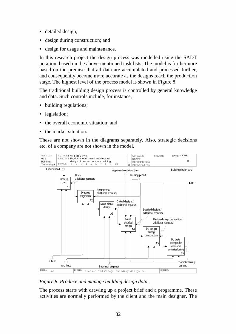
In this research project the design process was modelled using the SADTnotation, based on the above-mentioned task lists. The model is furthermorebased on the premise that all data are accumulated and processed further,and consequently become more accurate as the designs reach the productionstage. The highest level of the process model is shown in Figure 8.
The traditional building design process is controlled by general knowledgeand data. Such controls include, for instance,
• building regulations;
• legislation;
• the overall economic situation; and
• the market situation.
These are not shown in the diagrams separately. Also, strategic decisionsetc. of a company are not shown in the model.
Draw up brief
A1
Draw up programme
A2Make global
design
A3
Make detailed design
A4 Do design during
construction
A5Do tasks
during take over and
commissioningA6
Brief/additional requests
Programme/additional requests
Global designs/additional requests
Detailed designs/additional requests
Design during construction/additional requests
Complementarydesigns
O1
Building design data
USED AT: CONT EXT :
NODE: TITLE: NUMBER:A0 Produce and manage building design d a
AUTHOR:PROJECT:
NOTES: 1 2 3 4 5 6 7 8 9 10
WORKINGDRAFTRECOMMENDEDPUBLICATION
READER DATEVTT RTE VKKProduct model based architecturaldesign of precast concrete building
VTTBuildingTechnology X
C1Client's need
Client
Architect Structural engineer
Approved cost objectives
Building permit
Figure 8. Produce and manage building design data.
The process starts with drawing up a project brief and a programme. Theseactivities are normally performed by the client and the main designer. The
33
main architectural design process begins in the activity A3 Make globaldesign. The architect’s tasks during briefing and programming are usuallyconsidered as the main designer’s tasks. The main designer may be anarchitect or a group of persons and the tasks include co-ordination of thedesign work.
There are other published divisions or classifications of the constructionprocess. An ISO technical report divides the process into the design phase,production phase, use phase and the demolition phase [ISO 1993]. Thedesign phase includes activities such as briefing, environmental and spacedesign and constructional design. The integrated building process model(IBPM) divides the design process into the following activities: understandfunctional requirements, explore concepts, develop schematic, developdesign, communicate design to others and maintain design information andmodels [Sanvido 1990]. These activities overlap partly the Finnish model ofbuilding design process. Luiten analyses the building process from theinteraction point of view [Luiten 1994]. The process is divided into threesubactivities: design building, manage construction and constructbuilding.The model based on the existing Finnish guidelines was chosen asa starting point for this research since it reflects local conditions and theprevailing practice better than some of the foreign alternatives.
The project brief is a collection of basic information provided by the clientconcerning mainly space requirements. The information consists of needs,requirements and possibilities. The subactivities are:
• analyse present situation;
• define requirements;
• study alternatives for space acquisition; and
• prepare programme decision.
The project brief may lead to the definition of a building programme if thebrief indicates a substantial change in spatial needs which cannot beaccommodated through renovation or renting. The actual building programis usually defined by the client. In this process the design instructions areassembled. They contain:
• project-specific instructions;
• standards;
• instructions concerning documents;
• quality class definitions;
• special requirements for design;
• usage of quality management systems; and
• decision procedures concerning design solutions, etc.
34
The activities during the global design stage are based on the output of thebriefing and programming phases. The global design stage is further dividedinto three main phases.
• The first phase yields a basic solution in which masses and general sitedesigns are made.
• The second phase yields a proposed solution, which is based on a chosenbasic architectural solution. Feasibility analyses from the structural pointof view are carried out.
• The third phase, scheme design, is used to elaborate designs for theapplication of a building permit. The building permit can be obtainedwithin one month for a normal building in Finland.
The architect's main decisions concerning the facade are repeatable visiblesurfaces, openings and some details, such as details of windows in theglobal design stage. The facade is designed as a whole. In such cases wherethe technology used is precast element, the facade is divided into elementsonly later by the structural engineer.
4.3 The detailed design stage design
In the following we will only concentrate on a process where precastelements are used. During the detailed design stage all the parties becomeactively involved (architect, structural designer and manufacturer of thebuilding elements) and data exchange becomes essential. In the followingthe part of the model for the detailed design stage which concentrates on thefacades is further elaborated (Figure 9). The process for designing thefacade begins with the definition of the general shape of the facade.Openings and surfaces are usually designed next. Tiling may be designed ifit is needed. In the next activity, A4124 Define element division and joints,it should be noted that the element division may be determined either by thearchitect or by the structural engineer, depending on the agreement thatdefines the responsibilities of each participant. The figure shows thealternative where the structural engineer defines the element division andjoints. The last two activities are used to define some properties of thestructural layers and the edge shapes.

35
Defineshape offacade
A4121
Designopenings
andsurfaces
A4122 Designtiling
A4123Define
elementdivision
and joints
A4124 Define properties
of structurallayers
A4125Designedge
shapesA4126
Shape of facade/additional requests
Positions of opening, surfaces, areas/additional requests
Type of tiling, sizes, joints types,bond, size, shape/additional requests
Element division, joints, positions/additional requests
Layer thickness, k-value, fire class/additional requests
I1
Estimatedglobal designs/additionalrequests
O1
Data of facade/additional requests
USED AT: CONT EXT :
NODE: TITLE: NUMBER:A412 Design facad e
AUTHOR:PROJECT:
NOTES: 1 2 3 4 5 6 7 8 9 10
WORKINGDRAFTRECOMMENDEDPUBLICATION
READER DATEVTT RTE VKKProduct model based architecturaldesign of precast concrete building
VTTBuildingTechnology X
M1Architect M2Structural engineer
Figure 9. A part of the activity model for designing of a facade.
On a more generic level a typical information flow in the traditionalbuilding design process (when precast elements are used) goes from thearchitect to the structural engineer and further to the manufacturer, seeFigure 10. The data from the architectural design are usually presented inthe form of drawings (today predominantly produced using computers)which need to be interpreted by humans on the receiving side.
ArchitectStructuralengineer
Manufacturer
Feedback
Manual data exchange (drawings etc.)
Computer interpretable data exchange
Figure 10. A typical information sequence during a building design processduring the design of structural prefabricated components.

36
Structural engineering and prefabrication applications can exchange datamore directly without human interpretation since many software systemscontrolling the manufacturing process are able to receive data in somestandardised formats. Some feedback information can also be fed back fromthe manufacturing process (dashed line).
4.4 Analysis of current problems
Information concerning present day problems, related to this process, wasgathered in interviews with experts from the companies that collaborated inthe research project (see also Table 1).
Current problems include:
• The data concerning the facade which are produced during the differentphases of the architectural design process do not meet the informationcontent and format requirements of the other parties using theinformation as input to their own activities.
• there is insufficient feedback of requirements, experience data etc. fromthe latter stages back to the architectural design
The traditional building design process as such no longer corresponds to thedemands of today. If contractual aspects are set aside, one of the maincauses of problems outlined above has been the lack of standard datadefinitions for information exchange in various design stages. This leads toa variety in contents and accuracy in the design documents. Paper drawingsmay be interpreted by humans but not by computers.
Traditionally, data exchange involving architectural design is done viapaper documents, i.e., drawings, though the design data produced is indigital format. The usage of paper documents is caused partly by the lack ofdata exchange standards and partly by the fact that the data contents havenot been agreed on beforehand. The results of the architectural design arepassed to the structural engineer who then uses his own softwareapplications to do the appropriate feasibility analyses. The documentsproduced are drawings and written specifications. These may beunstructured and their data accuracy and reliability is often insufficient. Theinput of data to other systems is made by manual inspection of the drawingsdespite the fact that CAD-systems may have been used to produce thesedrawings in the first place. This often leads to misinterpretation of the data.
At the end of this process, it is difficult for the manufacturer to estimatecosts. Inaccurate designs produced during the tender stage cause difficultiesin determining the costs. In many cases the cost objectives that were setduring programming have to be revised or a lower quality level must beaccepted. On the other hand, the data from the structural engineering designmay be passed to the manufacturer in a computer interpretable format.

37
Tenders are based on the experience of the person who calculates them andon using typical elements as a basis for the calculations. A tender offer bythe manufacturer is based on using a typical element as the basis for the costestimation. The choice of this typical element is in many cases not correctwhich gives a wrong total cost effect. Experience from previous projectsand solutions is not used sufficiently. The element design is in many casesdone in a hurry. This easily leads to a lower level of quality.
The information process described above often leads to reuse of standarddesign solutions. It leaves little or no time for innovations and newtechnology suggested by the manufacturer (feedback). There are examplesof feedback from the manufacturer to the architectural design but thefeedback is usually not sufficient to enable new solutions instead ofstandard solutions. Luiten [Luiten 1994] points out that there is noformalised way to exchange comments or suggestions from construction todesign. More information exchange is needed.

38
39
5. THE PRODUCT DATA MODEL OF A FACADE
5.1 Modelling procedure
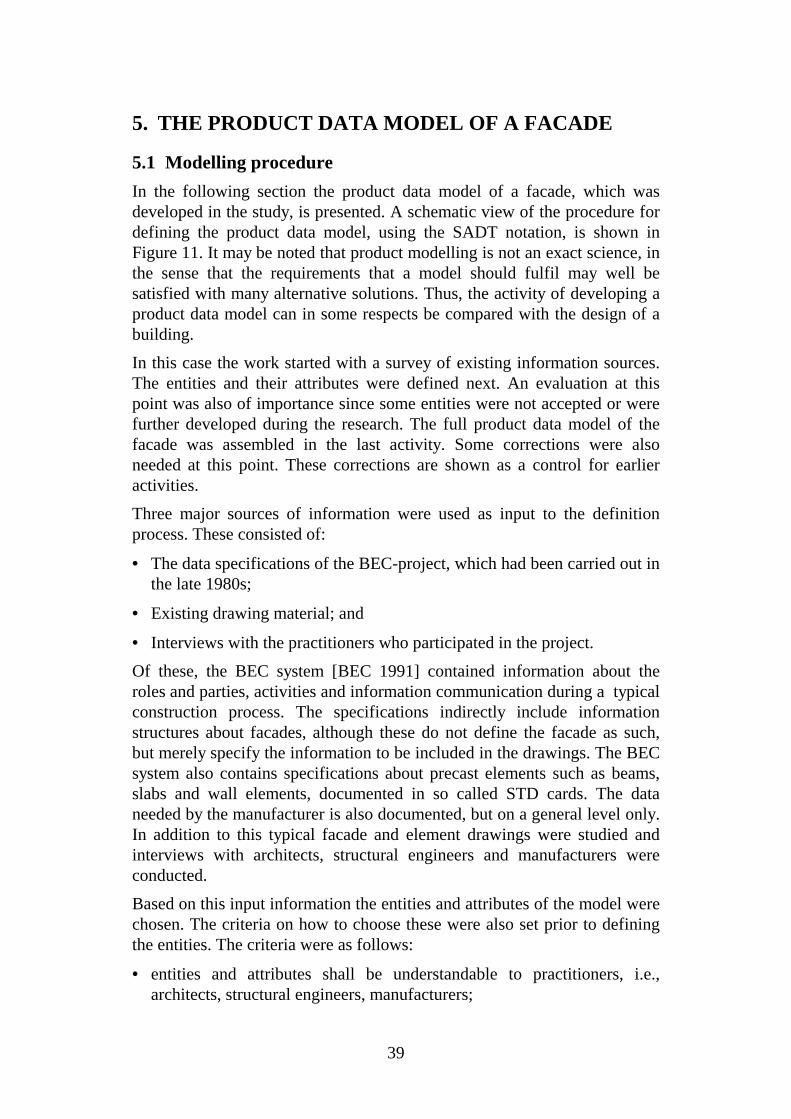
In the following section the product data model of a facade, which wasdeveloped in the study, is presented. A schematic view of the procedure fordefining the product data model, using the SADT notation, is shown inFigure 11. It may be noted that product modelling is not an exact science, inthe sense that the requirements that a model should fulfil may well besatisfied with many alternative solutions. Thus, the activity of developing aproduct data model can in some respects be compared with the design of abuilding.
In this case the work started with a survey of existing information sources.The entities and their attributes were defined next. An evaluation at thispoint was also of importance since some entities were not accepted or werefurther developed during the research. The full product data model of thefacade was assembled in the last activity. Some corrections were alsoneeded at this point. These corrections are shown as a control for earlieractivities.
Three major sources of information were used as input to the definitionprocess. These consisted of:
• The data specifications of the BEC-project, which had been carried out inthe late 1980s;
• Existing drawing material; and
• Interviews with the practitioners who participated in the project.
Of these, the BEC system [BEC 1991] contained information about theroles and parties, activities and information communication during a typicalconstruction process. The specifications indirectly include informationstructures about facades, although these do not define the facade as such,but merely specify the information to be included in the drawings. The BECsystem also contains specifications about precast elements such as beams,slabs and wall elements, documented in so called STD cards. The dataneeded by the manufacturer is also documented, but on a general level only.In addition to this typical facade and element drawings were studied andinterviews with architects, structural engineers and manufacturers wereconducted.
Based on this input information the entities and attributes of the model werechosen. The criteria on how to choose these were also set prior to definingthe entities. The criteria were as follows:
• entities and attributes shall be understandable to practitioners, i.e.,architects, structural engineers, manufacturers;

40
• entities and attributes shall be implementable in current softwareplatforms; and
• entities shall have a close correspondence with real life objects.
The structural layer is a typical entity. An element consists of a number ofstructural layers. The outer layer is usually designed by the architectwhereas the inner layers are determined by the structural engineer. Thus, afluent information exchange is needed. The surfaces determine themanufacturing sequence. The casting of a structural layer, for instance, isdone with the element face down which means that the tiles must be laidfirst on the mould.
C2
Process
C1
Problems
O1
Objectdefinitioncards
O2
Productdatamodel
C3
Conceptualmodelling
I1
Relatedresearch
I2
Existingspecifications
Surveyexisting
definitions
A21
Determinecriteria
A22
Defineentities
A23
Defineattributes
A24
Evaluate
A25
Assembleproduct
data modelA26
Survey
Criteria
Entities
Attributes
Acceptedentities andattributes
Not acceptedentities andattributes
Interviews
M1
Researcher
M2
EXPRESS-tool
Corrections
Figure 11. The procedure used in this research to assemble the productdata model of the facade.
In the following the model is presented in the following way. First theoverall abstraction hierarchy is discussed. After that the major parts whichare designed during the architectural design process (see also Figure 9) areshown and discussed. These include:
• structural layers;
• openings;
• surfaces; and
• edges.
Finally, the product data model as a whole is presented.
41
5.2 The decomposition hierarchy of facade
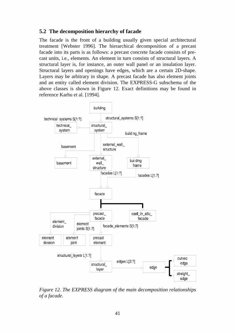
The facade is the front of a building usually given special architecturaltreatment [Webster 1996]. The hierarchical decomposition of a precastfacade into its parts is as follows: a precast concrete facade consists of pre-cast units, i.e., elements. An element in turn consists of structural layers. Astructural layer is, for instance, an outer wall panel or an insulation layer.Structural layers and openings have edges, which are a certain 2D-shape.Layers may be arbitrary in shape. A precast facade has also element jointsand an entity called element division. The EXPRESS-G subschema of theabove classes is shown in Figure 12. Exact definitions may be found inreference Karhu et al. [1994].
straight_edge
precast_facade
external_wall_
structurebasement
technical_system
cast_in_situ_facade
precast_element
element_division
element_joint
structural_layer
edge
facade
edges L[2:?]
element_division
element_joints S[1:?]
facade_elements S[1:?]
building
structural_system
structural_systems S[1:?]technical_systems S[1:?]
facades L[1:?]
building_frame
facades L[1:?]
building_frame
external_wall_structure
basement
curved_edge
structural_layers L[1:?]
Figure 12. The EXPRESS diagram of the main decomposition relationshipsof a facade.
42
Going upwards in the decomposition hierarchy we see that a facade is a partof the object called external wall structure, which in turn is a part of thestructural system. Highest up we find the building object itself. This part ofthe product data model is important for positioning the data in the context ofan overall building product model, but was not relevant for the testingperformed in this project.
A facade may be a part of the external wall structure and a building frame.These in turn are parts of the structural system. In practice, a load bearingfacade is considered as part of the building frame, a non-bearing facadebelongs to the external wall structure. In this research the main focus was onthe facade itself.
5.3 Structural layer
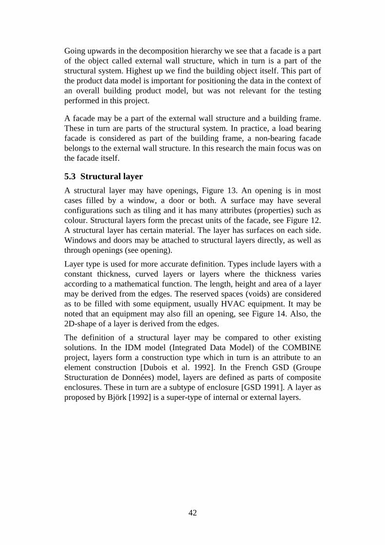
A structural layer may have openings, Figure 13. An opening is in mostcases filled by a window, a door or both. A surface may have severalconfigurations such as tiling and it has many attributes (properties) such ascolour. Structural layers form the precast units of the facade, see Figure 12.A structural layer has certain material. The layer has surfaces on each side.Windows and doors may be attached to structural layers directly, as well asthrough openings (see opening).
Layer type is used for more accurate definition. Types include layers with aconstant thickness, curved layers or layers where the thickness variesaccording to a mathematical function. The length, height and area of a layermay be derived from the edges. The reserved spaces (voids) are consideredas to be filled with some equipment, usually HVAC equipment. It may benoted that an equipment may also fill an opening, see Figure 14. Also, the2D-shape of a layer is derived from the edges.
The definition of a structural layer may be compared to other existingsolutions. In the IDM model (Integrated Data Model) of the COMBINEproject, layers form a construction type which in turn is an attribute to anelement construction [Dubois et al. 1992]. In the French GSD (GroupeStructuration de Données) model, layers are defined as parts of compositeenclosures. These in turn are a subtype of enclosure [GSD 1991]. A layer asproposed by Björk [1992] is a super-type of internal or external layers.
43
R E A L
S TR IN G
edge
layer_type
surface
opening
reserved_space
w indow
door
clam p
other_equipm ent
edges L[1 :?]
nam e_of_ layer
type_of_ layer
surfaces S [1:?]
openings S [1 :?]
reserved_spaces S [1 :?]
w indow s S [1:?]
doors S [1:? ]
c lam ps S [1:?]
o ther_equipm ents S [1:? ]
(D E R ) s l_ length
(D E R ) s l_height
(D ER ) sl_area
(D ER ) shape
m ateria ls S [1:?]
shape2D
m ateria l
openings S [1:? ]
w indow s S [1:?]
s tructura l_layer
Figure 13. The information structure for a structural layer.
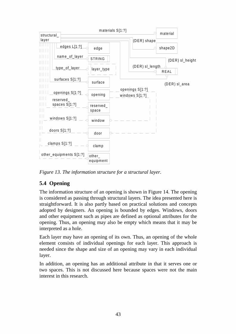
5.4 Opening
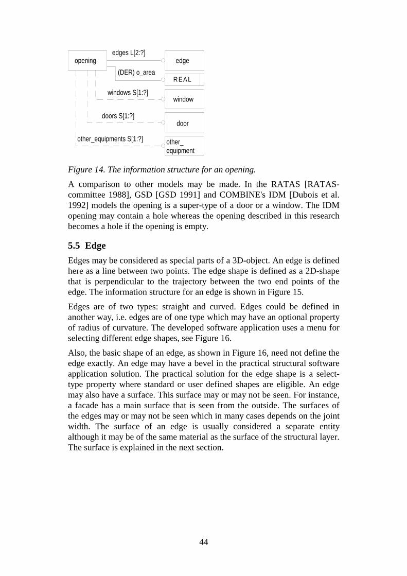
The information structure of an opening is shown in Figure 14. The openingis considered as passing through structural layers. The idea presented here isstraightforward. It is also partly based on practical solutions and conceptsadopted by designers. An opening is bounded by edges. Windows, doorsand other equipment such as pipes are defined as optional attributes for theopening. Thus, an opening may also be empty which means that it may beinterpreted as a hole.
Each layer may have an opening of its own. Thus, an opening of the wholeelement consists of individual openings for each layer. This approach isneeded since the shape and size of an opening may vary in each individuallayer.
In addition, an opening has an additional attribute in that it serves one ortwo spaces. This is not discussed here because spaces were not the maininterest in this research.
44
R EAL
opening edge
window
door
other_equipment
edges L[2:?]
(DER) o_area
windows S[1:?]
doors S[1:?]
other_equipments S[1:?]
Figure 14. The information structure for an opening.
A comparison to other models may be made. In the RATAS [RATAS-committee 1988], GSD [GSD 1991] and COMBINE's IDM [Dubois et al.1992] models the opening is a super-type of a door or a window. The IDMopening may contain a hole whereas the opening described in this researchbecomes a hole if the opening is empty.
5.5 Edge
Edges may be considered as special parts of a 3D-object. An edge is definedhere as a line between two points. The edge shape is defined as a 2D-shapethat is perpendicular to the trajectory between the two end points of theedge. The information structure for an edge is shown in Figure 15.
Edges are of two types: straight and curved. Edges could be defined inanother way, i.e. edges are of one type which may have an optional propertyof radius of curvature. The developed software application uses a menu forselecting different edge shapes, see Figure 16.
Also, the basic shape of an edge, as shown in Figure 16, need not define theedge exactly. An edge may have a bevel in the practical structural softwareapplication solution. The practical solution for the edge shape is a select-type property where standard or user defined shapes are eligible. An edgemay also have a surface. This surface may or may not be seen. For instance,a facade has a main surface that is seen from the outside. The surfaces ofthe edges may or may not be seen which in many cases depends on the jointwidth. The surface of an edge is usually considered a separate entityalthough it may be of the same material as the surface of the structural layer.The surface is explained in the next section.

45
R EA L
edge poin t
surface
edge_shape
corner_po in ts L [2 :2 ]
surfaces S [1 :? ]
edge_shape
beve ls L [1 :?]
beve l
stra ight_edge
curved_edge
rad ius_of_curvature
Figure 15. The information structure for an edge.
An example of the interface for defining shapes of edges is shown in Figure16. The user may select an appropriate edge shape by clicking on thedesired shape.
Figure 16. Architect's edges-menu. Six different edge shapes in 2D areshown.
5.6 Surface
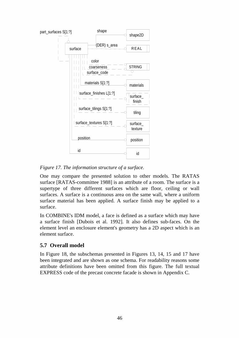
The information structure of a surface is shown in Figure 17. In practicalapplications the 2D-shape is needed to determine areas of certain surfacetypes. A surface may have many material alternatives, it may have a surfacefinish and may also have different surface patterns. Tiling may be attachedto a surface, see also Figure 20. A manufacturer may calculate costs interms of areas of different surfaces. A surface finish is chosen from a list.
The definition of a surface is of importance since it in many casesdetermines exactly the work order in manufacturing.
46
STRING
R EAL
color
shape
(DER) s_area
surface_finishes L[1:?]
coarseness
surface_tilings S[1:?]
materials S[1:?]
surface_textures S[1:?]
surface_code
part_surfaces S[1:?]
position
id
shape2D
materials
surface_finish
tiling
surface_texture
position
id
surface
Figure 17. The information structure of a surface.
One may compare the presented solution to other models. The RATASsurface [RATAS-committee 1988] is an attribute of a room. The surface is asupertype of three different surfaces which are floor, ceiling or wallsurfaces. A surface is a continuous area on the same wall, where a uniformsurface material has been applied. A surface finish may be applied to asurface.
In COMBINE's IDM model, a face is defined as a surface which may havea surface finish [Dubois et al. 1992]. It also defines sub-faces. On theelement level an enclosure element's geometry has a 2D aspect which is anelement surface.
5.7 Overall model
In Figure 18, the subschemas presented in Figures 13, 14, 15 and 17 havebeen integrated and are shown as one schema. For readability reasons someattribute definitions have been omitted from this figure. The full textualEXPRESS code of the precast concrete facade is shown in Appendix C.

47
straight_edge
precast_facade
external_wall_
structurebasement
tile
cast_in_situ_
facade
precast_element
element_division
element_joint
structural_layer
edge
opening
window
door
reserved_space
clamp
surface
surface_finish
tiling
facade
joint
bond
frame
material
surface_pattern
openings S[1:?]
windows S[1:?]
doors S[1:?]
reserved_spaces S[1:?}
clamps S[1:?]
edges L[2:?]
tilings S[1:?]
joints S[1:?]
surface_tiles S[1:?]
bond
windows S[1:?] doors S[1:?]
surface_pattern
materials S[1:?]
materials S[1:?]materials S[1:?]
other_equipment
other_equipments S[1:?]
other_equipments S[1:?]
surfaces S[1:?]
element_division
element_joints S[1:?]
facade_elements S[1:?]
surface_finishes L[1:?]
building
structural_system
structural_systems S[1:?]technical_systems S[1:?]
facades L[1:?]
building_frame
facades L[1:?]
building_frameexternal_wall_structure
basement
frame
frame
curved_edge
technical_system
structural_layers L[1:?]
Figure 18. The overall EXPRESS-G-diagram of the facade.

48
49
6. CHECK LISTS
6.1 Formulation of the check lists
Check lists are a practical solution that helps in defining the data re-quirements during the different design stages. In this study check lists weredefined based on the activities in the process model (see Figure 9) and theentities and attributes of the product model (Figure 18).
The entities that are of importance in each design stage were selected fromthe product data model of the facade. The data accuracy and contents of anentity, such as a structural layer, changes during the design process. Thus,same entities are designed more than once but in different level of detail.
For instance, a manufacturer and an architect may agree that the data in theglobal design stage shall include the shape and position of the facade andthe type of the element joints. The element division may be determined bythe architect or by the structural engineer.
An example of a part of a check list is shown in Table 2. The examplecheck list has two main entities that are the facade and the structural layer.A number of attributes to these are also shown in the list.
The global design stage will produce enough information for the applicationfor the building permit. The data during the first stage in the detailed designstage will be used for the invitation of tenders. This stage may be calledtender design. The manufacturer will calculate costs on the basis of thesedata. The invitation of tenders will be complemented by other partiesinvolved, e.g., the structural engineer. After the selection of themanufacturer the detailed design will produce the initial data for thedetailed element design. This stage may be called initial element design.The design is further elaborated by the structural engineer and it will finallyproduce all the necessary data for the manufacturing process.
The use of check lists results in a clear definition of the data generation andflow during the whole building design process. The data producer and thedata user could also be shown in the lists.
Each activity outputs some data concerning the facade. To constructionprofessionals the check lists are more readable than the product model orthe activity model.
The areas of different surfaces and element types could also be added to thecheck lists. This is purely for practical reasons as manufacturers usuallycalculate costs based on areas.

50
Table 2. An extract from a check list.
CHECK LIST Globaldesign
Tenderdesign
Initialelementdesign
Facade
facade shape x x x
position x x x
element division position x x x
element joint type x x x
width x x
length x
2D-shape x x
position x x
joint material name x x
colour x x
Structural layer
structural layer layer type x x
thickness x x
layer material name x x x
thermal property u-value x x x
layer edge edge shape x x
corner points x x x
bevel x
position x x x
edge surface (as layer surface)
layer surface 2D-shape x x x
area x x x
colour x x x
position x x x
surface material name x x x
colour x x x
surface finish type x x x

51
6.2 Possible uses of the check lists
These checklists can be used in a number of ways:
• They can provide additional material that helps in determiningsubcontract boundaries;
• They can be used to educate project participants so that they understandthe design management aspects better;
• They can be incorporated in quality insurance manuals; and
• They can be used as input to the software development projects.
The check-lists may be used as supplements to contracts. The same checklist may be used to define data needs during different design stages as wellas for defining limitations and subcontract boundaries. A typical exampleconcerns the element division since it may be defined either by the architector the structural engineer. The project participants may get a clearer view ofthe importance of the entities during the design process. The check lists mayalso be used in the quality insurance manuals, especially when new projectswith new participants are started. Software developers may also profit fromthe check lists since the data management and information flow is clearlydefined.
The check lists that were developed during this research were furtherincluded in a guideline issued by the Building Information Institute inFinland [RT 1994]. This guideline is focused on precast concrete structures.Thus, it contains information about wall structures, slabs, beams andcolumns. All design stages are included and examples of data exchangeformats given.

52

53
7. DEVELOPING PROTOTYPE SOFTWARE
7.1 Implementation of type objects
A prototype computer application was developed to test the product datamodel. The software platform was AutoCAD. The reasons for this choicewere that the architectural company involved in the research uses it and thatit has been used for many prototype applications by the research group atVTT Building Technology.
An important data structure which was incorporated in the prototype is theuse of so-called type objects to define common properties of one or moreinstance objects. This is an important aspect of several of the genericproduct model proposals that have been defined (GARM, OOCAD, IAIcore). Instance objects (the actual individual elements of a facade) areusually defined as occurrences of type objects (template definitions ofstandard types of elements). Type objects may also be nested, that is consistof a number of child objects which are instances of other type objects[Serén et al. 1993].
The feature of AutoCAD which was used in the initial phase of theprototype development was the so-called block. Blocks can be used toimplement type objects. A Block is a named assembly of graphical objectsand attribute definitions. Graphical objects are lines, polylines, etc..Attribute definitions contain alphanumeric information. Additionally, aBlock may contain an instance of another block.
It turned out that it is difficult to modify blocks dynamically during thedesign procedure for which reason they were not used in later prototypes.The product model was consequently later implemented using AutoCAD'sextended entity data feature [AutoCAD 1992].
The physical data exchange between the different applications wasimplemented as OXF files. OXF is an object-based data exchange formatdeveloped in a research project at VTT [Serén et al. 1993]. In scope, it israther similar to the STEP physical file format [ISO 1994]. The main reasonto use OXF was the availability of software supporting the generation ofOXF files from AutoCAD as well as the technical features of the format. Inparticular OXF has been designed to support type and instance objects. Afuller explanation of OXF is, however, outside the scope of this paper.
The principle of the CAD-implementation is shown in Figure 19. The figureshows how type and instance objects were implemented in AutoCAD and inthe neutral data exchange file.
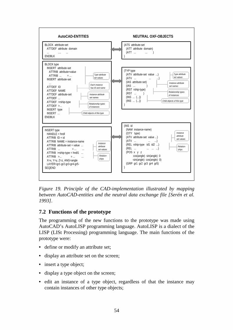
54
AutoCAD-ENTITIES NEUTRAL OXF-OBJECTS
BLOCK attribute-set ATTDEF attribute domain ... .... ...ENDBLK
BLOCK type INSERT attribute-set ATTRIB attribute=value ATTRIB ... = ... INSERT attribute-set ... ATTDEF ID ATTDEF NAME ATTDEF attribute-set ATTDEF ... ATTDEF >rship-type ATTDEF >... INSERT type INSERT ...ENDBLK
(TYP type (ATV attribute-set value ...) (ATV ... ... ...) (IAS attribute-set) (IAS ... ) (RST rship-type) (RST ... ) (INS ... (...)) (INS ... (...)))
(ATS attribute-set (ATT attribute domain) (ATT ... ... ))
INSERT type HANDLE = hndl ATTRIB ID = id ATTRIB NAME = instance-name ATTRIB attribute-set = value ... ATTRIB ... = ... ... ATTRIB >rship-type = hndl1 ... ATTRIB >... = ... ... X=x, Y=y, Z=z, ANG=angle LAYER=gr1-gr2-gr3-gr4-gr5-SEQEND
Type attributeset values
Each instancehas ID and name
Instance attributeset names
Relationship typesof instances
Child objects of this type
Instanceattribute set values
Relation-ships
Type attributeset values
Instance attributeset names
Relationship typesof instances
Child objects of this type
(INS id (NAM instance-name) (OTY type) (ATV attribute-set value ...) (ATV ... ... ...) (REL rship-type id1 id2 ...) (REL ... ... ... ...) (POS x y z cos(angle) sin(angle) 0 -sin(angle) cos(angle) 0) (GRP gr1 gr2 gr3 gr4 gr5))
Instanceattribute set values
Relation-ships
Figure 19. Principle of the CAD-implementation illustrated by mappingbetween AutoCAD-entities and the neutral data exchange file [Serén et al.1993].
7.2 Functions of the prototype
The programming of the new functions to the prototype was made usingAutoCAD’s AutoLISP programming language. AutoLISP is a dialect of theLISP (LISt Processing) programming language. The main functions of theprototype were:
• define or modify an attribute set;
• display an attribute set on the screen;
• insert a type object;
• display a type object on the screen;
• edit an instance of a type object, regardless of that the instance maycontain instances of other type objects;
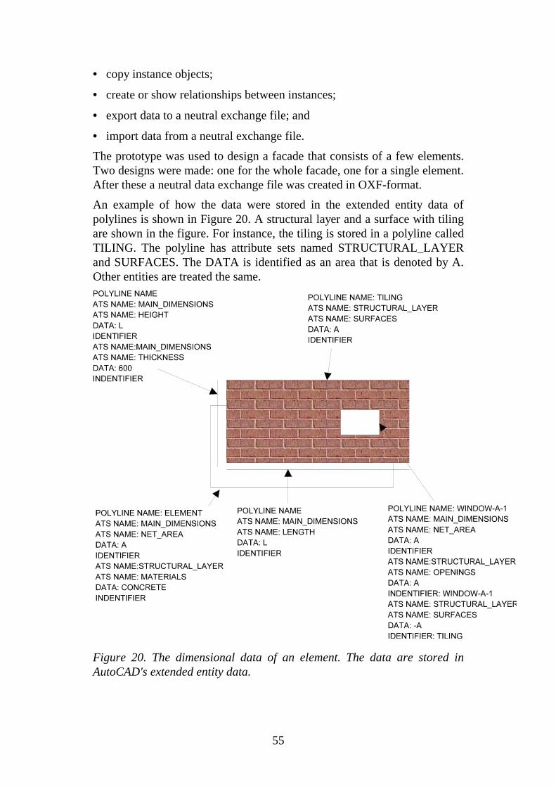
55
• copy instance objects;
• create or show relationships between instances;
• export data to a neutral exchange file; and
• import data from a neutral exchange file.
The prototype was used to design a facade that consists of a few elements.Two designs were made: one for the whole facade, one for a single element.After these a neutral data exchange file was created in OXF-format.
An example of how the data were stored in the extended entity data ofpolylines is shown in Figure 20. A structural layer and a surface with tilingare shown in the figure. For instance, the tiling is stored in a polyline calledTILING. The polyline has attribute sets named STRUCTURAL_LAYERand SURFACES. The DATA is identified as an area that is denoted by A.Other entities are treated the same.
Figure 20. The dimensional data of an element. The data are stored inAutoCAD's extended entity data.
56
7.3 The final prototype
The final prototype application that was used in a test project (see nextchapter) was developed in the architectural company. This application alsouses AutoCAD's extended entity data for storing the information. Thearchitect’s AutoCAD was version 12.
The final prototype application has a simple interface that enables a user tocreate an id for an element and attributes that are needed. The functions thatwere included in this application were:
• design of an element;
• design of an area;
• design of an edge and joints; and
• output to a file.
The prototypes take into account the architect's normal way of design. Thismeans that the produced data are more accurate and detailed in the laterdesign stages (from the global design stage to the detail design stage). Also,as mentioned earlier, the architectural data focuses more on surfaces andopenings, not structural details.
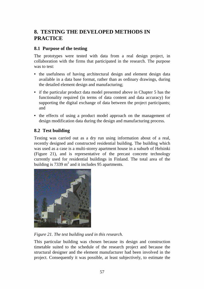
57
8. TESTING THE DEVELOPED METHODS INPRACTICE
8.1 Purpose of the testing
The prototypes were tested with data from a real design project, incollaboration with the firms that participated in the research. The purposewas to test:
• the usefulness of having architectural design and element design dataavailable in a data base format, rather than as ordinary drawings, duringthe detailed element design and manufacturing;
• if the particular product data model presented above in Chapter 5 has thefunctionality required (in terms of data content and data accuracy) forsupporting the digital exchange of data between the project participants;and
• the effects of using a product model approach on the management ofdesign modification data during the design and manufacturing process.
8.2 Test building
Testing was carried out as a dry run using information about of a real,recently designed and constructed residential building. The building whichwas used as a case is a multi-storey apartment house in a suburb of Helsinki(Figure 21), and is representative of the precast concrete technologycurrently used for residential buildings in Finland. The total area of thebuilding is 7339 m2 and it includes 95 apartments.
Figure 21. The test building used in this research.
This particular building was chosen because its design and constructiontimetable suited to the schedule of the research project and because thestructural designer and the element manufacturer had been involved in theproject. Consequently it was possible, at least subjectively, to estimate the
58
effects of using the product model approach, compared to the normal dataexchange practice which had been used in the project. In the test, a part ofthe eastern facade of the building (storeys 13-15) was redesigned and thedata were exchanged between the project participants as in the real project.
8.3 Software
In addition to the prototypes that were developed as a part of this studycommercial applications had to be used in order to complete the wholedesign and manufacturing ”circle”. The resources available for the researchwere not sufficient for the development of prototypes that would havecovered all the necessary tasks.
The software tools that were used in the testing are listed below:
The architectural designer used:
• Prototypes developed in the study on top of AutoCAD (version 12).
The structural or element designer used the following modules ofConcreteCAD:
• Gides (whole building, whole facades);
• Exwall (detailed element design).
The element manufacturer used:
• ConcreteCAD;
• In-house CAM-software of Partek.
ConcreteCAD is suite of software modules which have been tailor-made forthe design and manufacturing of prefabricated concrete buildings[ConcreteCAD 1992]. It is widely used in Finland and has users also inseveral other countries. The structure of ConcreteCAD is centred on havingone and only one model of the building being designed, which is stored in acustomised database. Drawings and other output documents are generatedfrom the information in the database. ConcreteCAD was also chosenbecause the industry practitioners who participated in the testing werealready using it.
The manufacturer has a modern facility using computer controlledadjustable element moulds. The software used by the element manufacturerfor production control has a relational data base as its platform. In additionthe factory uses Concrete CAD for some in-house design applications.
8.4 Prototype software test
Some initial small-scale tests of the developed AutoCAD prototypes werecarried out before the actual design started. Special interest was focused onhow data from the architectural design stage may be directly used in theelement design. The architectural data that are defined and may be used are
59
modular dimensions, surfaces, openings and edge shapes (see also Figure9). In addition, the architectural data consists of details concerning windowclamps and fasteners. A number of corrections were made based on thefeedback received. The major points from the feedback were:
• The edges of elements were not stored in the architect’s model as itcontained only surfaces and shapes of edges.
• The local element co-ordination in the ConcreteCAD program iscalculated from the position of the first edge that is input to the database.This caused that an individual element had an arbitrary position when itwas input to the ConcreteCAD program.
• Some openings were not defined, they were just empty areas betweensurfaces.
• Some edge shapes were missing due to a bug in the architect’s program.
• The DXF conversion did not match exactly.
The following conventions were adopted to ensure better co-ordination:
• The origin of the local co-ordinate system of an element will be placedon the lower left corner of the element (seen from the outside of thebuilding). The first edge shall start from the origin.
• All openings shall be designed as real openings because a surface mayconsist of parts that form the whole surface. The initial tests showed thatthe architect's "opening" was just an area with no surface.
• The edges of an element shall be designed counter-clockwise.
• An element shall have an attribute which specifies the location of theelement in the global co-ordinate system.
8.5 Test design
After the modifications the actual test design was started. The testing wasdivided into two main phases:
• phase A included a normal design procedure; and
• phase B included a change in the design solution.
In the phase A the eastern facade of the building for storeys 13-15 wasdesigned. This included the design of the elements by the architect. Thearchitectural designs were used as input to the structural (element) design.The architectural design was started by generating modular dimensions,surfaces, thickness of structural layers and materials. The openings weredesigned next. The shapes of edges were designed for each individualstructural layer including shapes in the openings.

60
In the phase B the architect made two changes: an element wasredimensioned by 300 mm (width) and the position of one opening waschanged. These changes resulted in different proportions of surfacematerial. The changes are critical from the manufacturer's point of view.
The main interest in each phase, A and B, was focused partly on the reuse ofdata from the architect's application by the structural engineer's application,and partly on the exchange of data from the structural engineer's applicationto the manufacturer's system. In addition, possible errors and lack of datawere studied.
The testing was carried out in accordance with the activity model which hadbeen developed in the project. The test design "stage" corresponds to thedetail design stage in the activity model (see Figure 8 and Figure 9).
The architect used the application which had been developed in the project.This application creates a data base using the conceptual schema presentedabove, although this ”database” lacks some of the functionality of object-oriented or relational databases, since it has been implemented as part of asequential CAD file using AutoCAD’s extended entity data. The architectdesigned the surfaces, openings and some window details. Surfacesconsisted of many sub-surfaces. The types of edges, i.e., edge shapes, variedin the openings. The types were chosen using a menu, see Figure 16. Finallya data exchange file was produced in ASCII format.
In the next stage these data were transferred to the structural engineer’sConcreteCAD application. Although it would have been possible to writesoftware that could have done this conversion automatically, the conversionwas done manually, by interpretation of the human-readable files producedfrom the architect’s application. The reasons for this were purely due toresource restrictions, since developing such conversion software wouldhave cost too much, in comparison to the overall budget of the project. Thedata exchange was thus only simulated. The important thing is, however,that the data contained in the architect’s model was transferred to thereceiving application, not the speed of the conversion.
After this the element designer started his work using ConcreteCAD'sGides-module. The element division was chosen, based on the modulardimensions of the architectural design. The thickness and material typeswere designed for each structural layer. Elements were created according tothe element division. The element division is decided either by the architector the structural engineer, depending on what has been agreed. In thisexample, the architect decided the element division.
The edges were then defined. It showed that the architect had designededges of the outer wall layer using modular dimensions, for which reasonthey had to be moved inward by 7.5 mm. The insulation layer and the innerstructural layers were also treated in the same way. The openings were
61
designed using the same principle. The edges of openings had to be movedby a few millimetres because the architectural data used modulardimensions.
The rest of the structural design was accomplished as a normal design.Reinforcement and other equipment were defined. For further elaboration ofthe data, the following information for each element was saved in thedatabase of the structural designer:
• ID of the element (precast unit);
• name of each layer, dimensions and relative position;
• surfaces and their materials;
• size and relative position of opening;
• shape of edge of each layer;
• reinforcement rebars of each layer;
• shapes, size and relative position of reserved spaces;
• name, shape, size and relative position of additional equipment.
The position of each structural layer was relative to the position of theelement. Elements were positioned in the global co-ordinate system of thefacade.
Element joints may cause problems: module dimension versus realdimension. The architect may design joints exactly by shapes anddimensions but uses modular dimensions on positioning on the elementlevel. Another problem may occur: if the edge of an opening coincides withthe edge of a structural layer, i.e., the opening may not be considered as anopening anymore.
In the last stage, the structural engineer passed the designs to themanufacturer electronically using an Ethernet network. Since themanufacturer also used ConcreteCAD up-front no conversion was needed.A macro in ConcreteCAD's Exwall module created an ASCII-file in whichthe manufacturer added some internal parameters such as product typenumber and the name of the "lowest" layer during casting. This ASCII filewas then used as input information for the production planning software ofthe manufacturer.
In addition a material table in BEC-format [BEC 1991], [Hannus 1990] wascreated from the data transferred to the manufacturer. BEC was developedin Finland during the 1980s. The whole BEC-system includes a number ofsoftware modules for the receiving and manipulation of graphical BEC-filesand for the management of tables. The BEC formats are currently widelyused for data exchange to element manufacturers in Finland.

62
8.6 Results
The results of the tests were both quantitative and qualitative. Theparticipating designers were asked to compare the time used when using theproduct model approach to the way the work had originally been carriedout. The results were conclusive to some extent. The total amount of timespent was 20 % longer using the product model approach in phase A(normal design procedure). The design changes were 7 % longer. On theother hand this was largely due to the substantially increased workload ofthe element designer because some data were manually converted from thearchitect’s application to the element designer’s application. (The dataexisted in the architect’s designs but there was no conversion program.)
Both the architect and the manufacturer saved time. Compared to thedrawing oriented approach the manufacturer may make changesapproximately 30 % faster in the product model approach because the dataof an element is in computer interpretable format.
More important were the qualitative advantages which the participantstestified to in the interviews carried out. The conceptual schema of thefacade proved to be sufficient. This led to a better data accuracy and thedata content was clearly defined already at an early stage of the buildingdesign process. The test showed that the architectural data are usable assuch in the element design which means that the normal procedures ofarchitectural design need not be changed. Data in earlier building designstages are considered more general, i.e., facade is designed as a wholewhere surfaces and opening are placed.
The test also showed that having usable architectural data the elementdesigner may concentrate on essential design matters. Especially, the shapesof edges as defined by the architect reduced the routine design work of theelement designer. It is of importance to note that the shapes of edges dependon the manufacturer.
The manufacturer has an advantage: cost estimations may be done earlierthan normally. This will also enable more data interchange between thearchitect and the manufacturer because solutions may be based on themanufacturer’s suggestions. The automation level of the manufacturingprocess may be improved only through more accurate data.
In the long run such qualitative advantages will no doubt be converted intomonetary benefits due to shorted design times, fewer mistakes, etc.
8.7 Limitations and restrictions of the model
Limitations of the developed model exist. For instance, a window or a doormay be included in an opening which also means that an opening is alwayssurrounded by material of the structural layer. The opening is inside the

63
layer. But in some cases the opening is not inside of the layer. The problemis illustrated in Figure 22.
The edge of the opening coincides with the edge of the structural layer. Theopening is no more a normal opening but it becomes an opening in a facade.It also means that the window or a door is no more in an opening of a layerbut in an opening of the facade. The presented model is limited to openingsin the structural layers only. This type of structural layers are commonwhere balconies are attached, or generally where an entrance is needed.These “openings” are usually filled by a combination of a window and adoor.
Figure 22. The problems of an opening: a normal opening on the left isinside of the structural layer, the opening on the right is not inside of thelayer.

64

65
9. CONCLUSIONS
9.1 Usefulness of the results
The architectural description of a facade is complicated. The test verifiedthat the data defined by the architect such as modular dimensions, surfaces,openings and edge shapes, are usable directly in the structural design. Thus,the data are also usable for the manufacturer of the precast facades. It alsoshowed that it is possible to produce the data in computer interpretableformat without changing the "normal" design procedure. However, thisrequires well-designed computer applications. The product model basedapproach forces more accurate data definitions which in the long run resultsin cost reduction in terms of error and redundant design work reduction.
The SADT method was well suited for the overall description of theactivities that occur during the traditional building process. The integrationof the activity model with the conceptual model is of importance. Also, theinfluence of using the product model approach on the process itself is ofinterest, especially when feedback and experience from past designs andsolutions are to be used.
The basic results obtained in this project may be exploited in all stages ofthe process of designing and manufacturing prefabricated elements even ifthe test was focused on the detail design stage. Architects and otherparticipants in a design project may use the check-lists to define their dataneeds during all stages of the process.
Developers of software applications may utilise the object definition cardsand the conceptual schema of a precast facade to develop new softwareapplications. Also, manufacturers may standardise their data needs. Anumber of requirements need to be defined for the software applications.An application shall be able to handle:
• surfaces (material and area);
• openings (dimension and area);
• edge shapes of openings and structural layers;
• the facade as a whole;
• element joints; and
• the co-ordinates of a structural layer.
The coordinate systems for each object should also be standardised oragreed at the beginning of each project. Furthermore, applications shall notrestrict the design procedure of architect.

66
9.2 A possible way ahead - STEP and IFC
Extensive exploitation of the ideas and results presented here requiresstandardising the data exchange structures on the national or preferablyinternational level. ISO/STEP development [ISO 1994b] could be a solutionin the form of a possible application protocol for prefabricated facadeelements. Also, IAI (International Alliance for Interoperability) and its IFCs(Industry Foundation Classes) may provide solutions [IAI 1996] in the nearfuture. It is to be hoped that the results of this research could provide auseful input into these standardisation activities, in a sub-domain which isof particular importance to the Finnish construction industry.

67
ACKNOWLEDGEMENTSThis research was funded by the Technical Research Centre of Finland(VTT), The Finnish Association of Construction Products Industries (RTT)and the Technology Development Centre of Finland (TEKES). Thecompanies that participated in the testing were the architectural companyArkkitehtitoimisto Innovarch Oy, the structural engineering companyTampereen Juva Oy and the manufacturer Partek Betonila Oy. Thearchitect’s final software was developed by Studio Kivi Oy.
The following persons were interviewed or participated in the research:Christer Finne (Arkkitehtiryhmä Kråkström Oy), Seppo Niemioja andKimmo Setkänen (Arkkitehtitoimisto Innovarch Oy), Pertti Alho and TapioRistimäki (CADEX Oy), Aarni Heikkonen (CADOR Oy), AarnoMyllyniemi and Antti Laitakari (Finnmap Oy), Harto Räty (FinnmapPartners Oy), Heikki Järvinen (Juva Engineering Oy Ltd), Jouni Allen-Perkko, Pentti Jalonen and Timo Kannisto (Parma Oy), Heikki Sarín, KaleviGranlund, Matti Raukola, Timo Tuominen and Tuomo Svanlund (PartekBetonila Oy), Jari Tanskanen (Partek Parametri Oy), Riitta Takanen(Rakennustoimisto A. Puolimatka Oy, Arto Suikka and Seppo Petrow(RTT), Matti Rasilainen and Pekka Timonen (Runkotek Oy), ArtoKiviniemi (Studio Kivi Oy), Aarno Vainio (Tampereen Juva Oy), Olli-Pekka Nordlund (TEKES) and Asko Sarja (VTT Building Technology).

68
69
REFERENCESAppleton. 1985. Information modelling language IDEF1X. AppletonCompany Inc., USA.
AutoCAD. 1992. AutoCAD Version 12 Manual. Neuchatel, Autodesk BV.
BEC. 1991. Manual. Betonielementti-CAD. Helsinki: Finnish ConcreteAssociation.
Björk, B-C. 1992. A conceptual model of spaces, space boundaries andenclosing structures. Automation in Construction. Vol. 1, No. 3, pp. 193-214.
Björk, B-C. 1995. Requirements and information structures for buildingproduct data model. VTT Publications 245. Technical research centre ofFinland. Espoo.
Björk, B-C., Löwnertz, K. and Kiviniemi, A. 1996. ISO 13567 - theproposed international standard for structuring layers in computer aidedbuilding design. Proceedings of the CIB W78 and TG10 workshop onConstruction on the Information Highway, Bled. Pp. 77-88.
Björk, B.-C. and Penttilä, H. 1989. A scenario for the development andimplementation of a building product model standard. Advances inEngineering Software, vol. 11, no. 4, pp. 176-187.
Boman, M., Bubenko, J. and Johannesson, P. 1991. Conceptual modelling.Department of Computer and System sciences, Stockholm University.Second edition. Stockholm.
CIB. 1977. An introductory guide to the use of SfB. CIB Report No. 40.Conseil International du Bátiment pour la Recherche l´Etude et laDocumentation
Clayton, M. J., Fisher, M., Teicholz, P. and Kunz, J. 1997. Charrette TestingMethod. Working paper. http://http.tamu.edu/~mclay/mjc-arcc.htm
COMBINE. 1995. Integrated Data Model. The EXPRESS specification ofthe IDM. A World Wide Web document at URL:http://dutcu15.tudelft.nl/~combine/idm/index.html
ConcreteCAD. 1992. ConcreteCAD Manual. Cadex Oy. Finland.
Dale, S.I. 1991. Object-oriented product modeling for structural design.Division of Structural Engineering. The Norwegian Institute of Technology.Trondheim.
Dubois, A.-M., Escudié, J.-C. and Laret, L. 1992. COMBINE IntegratedData Model, Volume I - NIAM diagrams, Volume II - Dictionary, V.3.3,920123, CSTB, Sophia Antipolis, France.
Gielingh, W. 1988. General AEC reference model. ISO TC 184/SC4/WG1
70
doc. 3.2.2.1, TNO building and construction research, BI-88-150. Delft.
Gielingh, W. and Suhm, A.K. 1993. IMPPACT reference model: anapproach for integrated product and process modelling of discrete partmanufacturing. Springer Verlag. Darmstadt.
GSD. 1991. Synthese des modeles conceptuels développés dans le la cadrede la recherche batiment en France, Plan Construction et Architecture,Ministre de'l equipement, du logement, des transports et de l'espace, Paris.
Hannus, M. 1990. Computer aided design of component based buildings.Open Industrialization: A Solution for Building Modernization. Conferenceproceedings. Stuttgart. pp. 6-1 -6-9.
IAI. 1996. Industry Alliance for Interoperability.http://www.interoperability.com/
ISO. 1985. Concepts and terminology for the conceptual schema and theinformation base. ISO/DTR 9007 (TC 97). Published also as SIS technicalreport 311, Standardiseringskommissionen i Sverige, Stockholm.
ISO. 1993. Classification of Information in the Construction Process. ISOworking group TC59/ SC13 WG2, Technical Report N35E.
ISO. 1994a. International Standard DIS 10303 (STEP). Part 11: TheEXPRESS Language Reference Manual.
ISO. 1994b. International Standard DIS 10303 (STEP), Part 1: Overviewand fundamental principles. TC 184 SC 4
ISO. 1994c. International Standard DIS 10303 (STEP), Part 21: Clear textencoding of the exchange structure.
Jones, E. M. 1982. The design of a complex building using an integratedCAD-system. CAD 82 conference proceedings. Butterworths, Guildford,England.
Karhu, V., Hannus, M., Pellosniemi, J. 1994. Elementtirakennuksentuotemallipohjainen arkkitehtisuunnittelu [Product model based architecturaldesign of prefabricated building]. VTT Research Notes 1568. TechnicalResearch Centre of Finland, Espoo.
Karhu, V. 1997. Product Model Based Design of Precast Facades.http://itcon.org/1997/1/
Karlshøy, J. 1994. Principper og metoder for opstilling af datamodeller tilbyggetekniske anvendelser. Serie R. No. 315. Department of structuralengineering. Technical University of Denmark.
Lavakare, A. and Howard, C. 1989. Structural steel framing data model.Technical Report No. 012, CIFE, Stanford University, California.
Luiten, G. 1994. Computer Aided Design for Construction in the BuildingIndustry. Ph.D. thesis, Delft University of Technology.

71
Marca, D. A. and McGowan, C. L. 1987. SADT - structured analysis anddesign technique. New York, McGraw-Hill.
Nijssen, G. and Halpin, T. 1989. Conceptual schema and relational databasedesign, a fact oriented approach. Prentice Hall, London.
PM Glossary. 1996. http://www.vtt.fi/cic/service/glossary/glossary.html
RATAS-committee. 1988. Rakennuksen tuotemalli. (The building productmodel), Rakennuskirja Oy, Helsinki, Finland.
RATAS. 1996a. http://www.vtt.fi/cic/projects/ratasimp/
RATAS. 1996b. http://www.vtt.fi/cic/projects/ratasimp/edge.htm
RT. 1994. RT 10-10557. Valmisosarakentamisen tiedonhallinta.Betonielementtirakentaminen. [Building work. Precast concreteconstruction.]. Helsinki: Rakennustieto Oy. 20 p.
RT. 1995a. RT 10-10575. Rakennuttamisen tehtäväluettelo. [Scope of workclient's work in building construction.]. Helsinki: Rakennustieto Oy. 14 p.
RT. 1995b. RT 10-10576. Arkkitehtisuunnittelun tehtäväluettelo. [Scope ofwork in architectural design.]. Helsinki: Rakennustieto Oy. 12 p.
RT. 1995c. RT 10-10579. Talotekniikan suunnittelun tehtäväluettelo. [Scopeof work in building services design.]. Helsinki: Rakennustieto Oy. 12 p.
RT. 1995d. RT 10-10580. Geosuunnittelun tehtäväluettelo. [Scope of workin geotechnical design.]. Helsinki: Rakennustieto Oy. 8 p.
Sanvido, V. 1990. An Integrated Building Process Model, ComputerIntegrated Construction Research Program, Dept. of ArchitecturalEngineering, Pennsylvania State University, USA, Technical Report No. 1
Serén, K.- J., Hannus, M., Karstila, K., Kihlman, M. and Pellosniemi, J.1993. Object-oriented CAD tool implementations for the constructionindustry. VTT Research Notes 1460, Laboratory of Structural Engineering,Technical Research Centre of Finland, Espoo
Turner, J. 1990. AEC building systems model. ISO TC184/ SC4/ WG1,Doc. N363. Working paper.
Watson, A. 1995. To product models and beyond. In: Brandon, P. and Betts,M. (eds). Integrated construction information. E&FN Spon, London.pp.159-172.
Webster. 1996. http://gs213.sp.cs.cmu.edu/prog/webster?facade
WWW STEP. 1996a. http://www.scra.org/uspro/stds/ap_text.html
WWW STEP. 1996b. http://www.nist.gov/sc4/tools/express/

72
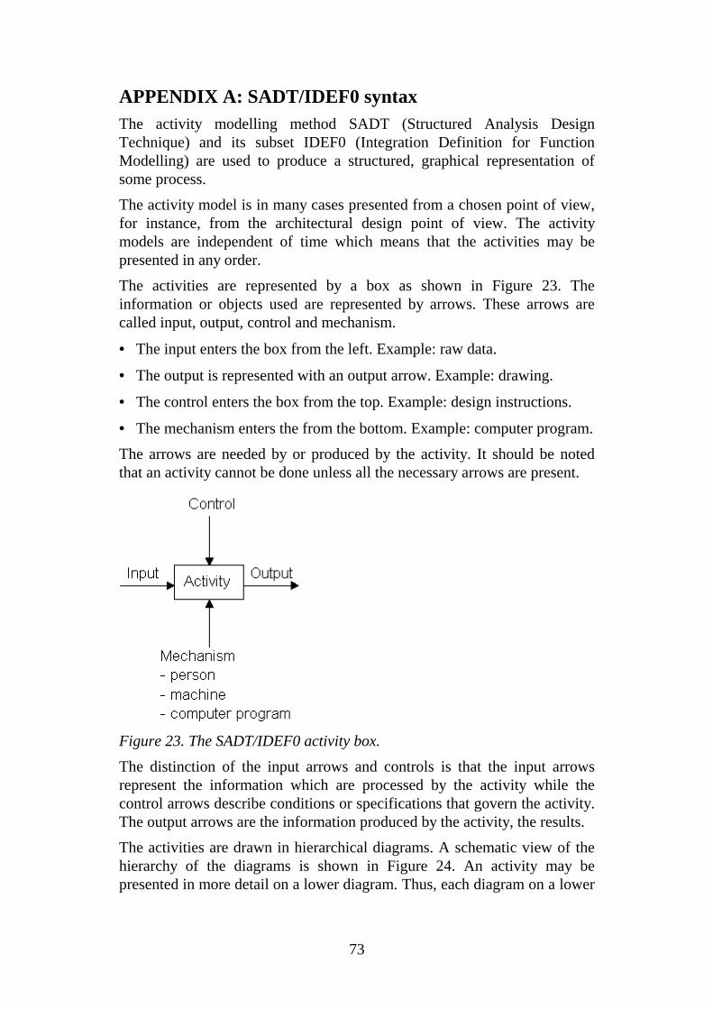
73
APPENDIX A: SADT/IDEF0 syntaxThe activity modelling method SADT (Structured Analysis DesignTechnique) and its subset IDEF0 (Integration Definition for FunctionModelling) are used to produce a structured, graphical representation ofsome process.
The activity model is in many cases presented from a chosen point of view,for instance, from the architectural design point of view. The activitymodels are independent of time which means that the activities may bepresented in any order.
The activities are represented by a box as shown in Figure 23. Theinformation or objects used are represented by arrows. These arrows arecalled input, output, control and mechanism.
• The input enters the box from the left. Example: raw data.
• The output is represented with an output arrow. Example: drawing.
• The control enters the box from the top. Example: design instructions.
• The mechanism enters the from the bottom. Example: computer program.
The arrows are needed by or produced by the activity. It should be notedthat an activity cannot be done unless all the necessary arrows are present.
Figure 23. The SADT/IDEF0 activity box.
The distinction of the input arrows and controls is that the input arrowsrepresent the information which are processed by the activity while thecontrol arrows describe conditions or specifications that govern the activity.The output arrows are the information produced by the activity, the results.
The activities are drawn in hierarchical diagrams. A schematic view of thehierarchy of the diagrams is shown in Figure 24. An activity may bepresented in more detail on a lower diagram. Thus, each diagram on a lower

74
level is a child diagram of the upper level diagram, the parent diagram. Theparent diagram is a sum of the child diagrams.
The hierarchy of the diagrams may be traced by the node number. The nodenumber is shown on the lower left corner of the diagram. The hierarchy mayalso be traced by the graphical context box that is shown on the upper rightcorner of the diagram.
A0
A3
More
genera
lM
ore
deta
iled
A32
A2
Each diagramhas a node
number, whichis formed bytaking the node
number of theparent diagram
and appending to it the numberof the box being decomposed
One squareis drawn for
each box onthe parentdiagram and
the one isshaded, which
the diagramdecomposes
Parent-child-
relation
Top A diagram containsboxes and arrows(not shown here);
external arrows ofa diagram must becompatible with
those of thecorresponding box
in a parent diagram
Figure 24. The hierarchical structure and reference systematic of the IDEF0
modelling system.
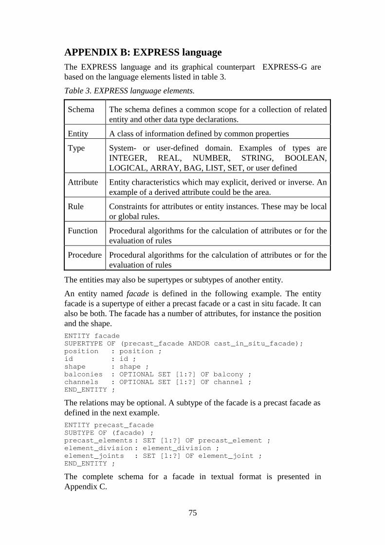
75
APPENDIX B: EXPRESS languageThe EXPRESS language and its graphical counterpart EXPRESS-G arebased on the language elements listed in table 3.
Table 3. EXPRESS language elements.
Schema The schema defines a common scope for a collection of relatedentity and other data type declarations.
Entity A class of information defined by common properties
Type System- or user-defined domain. Examples of types areINTEGER, REAL, NUMBER, STRING, BOOLEAN,LOGICAL, ARRAY, BAG, LIST, SET, or user defined
Attribute Entity characteristics which may explicit, derived or inverse. Anexample of a derived attribute could be the area.
Rule Constraints for attributes or entity instances. These may be localor global rules.
Function Procedural algorithms for the calculation of attributes or for theevaluation of rules
Procedure Procedural algorithms for the calculation of attributes or for theevaluation of rules
The entities may also be supertypes or subtypes of another entity.
An entity named facade is defined in the following example. The entityfacade is a supertype of either a precast facade or a cast in situ facade. It canalso be both. The facade has a number of attributes, for instance the positionand the shape.ENTITY facadeSUPERTYPE OF (precast_facade ANDOR cast_in_situ_facade);position : position ;id : id ;shape : shape ;balconies : OPTIONAL SET [1:?] OF balcony ;channels : OPTIONAL SET [1:?] OF channel ;END_ENTITY ;
The relations may be optional. A subtype of the facade is a precast facade asdefined in the next example.ENTITY precast_facadeSUBTYPE OF (facade) ;precast_elements : SET [1:?] OF precast_element ;element_division : element_division ;element_joints : SET [1:?] OF element_joint ;END_ENTITY ;
The complete schema for a facade in textual format is presented inAppendix C.
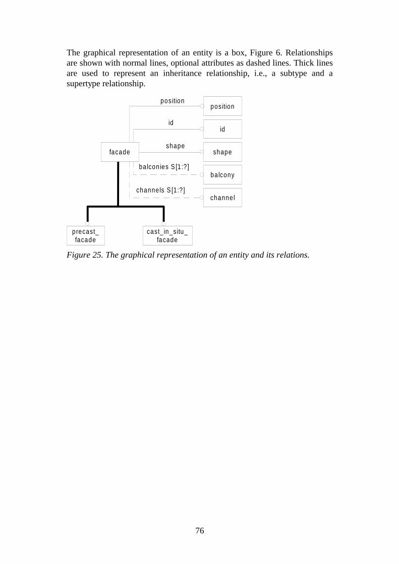
76
The graphical representation of an entity is a box, Figure 6. Relationshipsare shown with normal lines, optional attributes as dashed lines. Thick linesare used to represent an inheritance relationship, i.e., a subtype and asupertype relationship.
position
id
shape
balcon ies S [1 :? ]
channels S [1 :? ]
cast_ in_situ_facade
facade
precast_facade
shape
balcony
channel
id
position
Figure 25. The graphical representation of an entity and its relations.
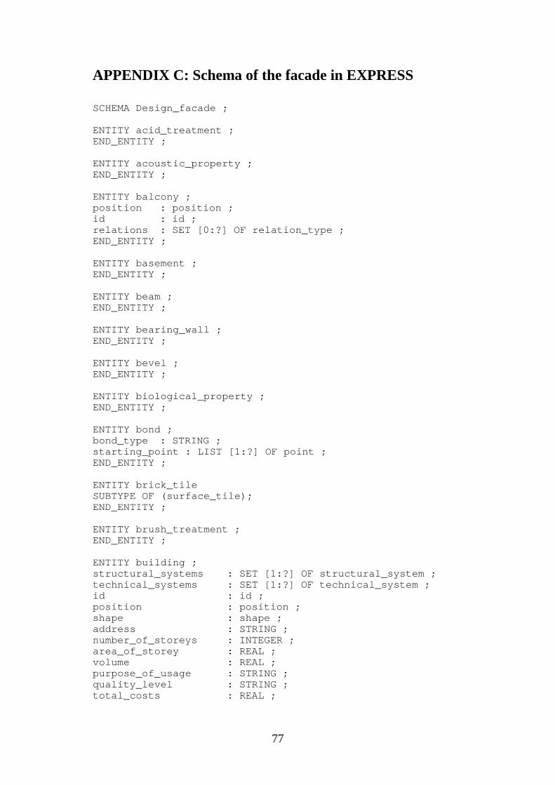
77
APPENDIX C: Schema of the facade in EXPRESS
SCHEMA Design_facade ;
ENTITY acid_treatment ;END_ENTITY ;
ENTITY acoustic_property ;END_ENTITY ;
ENTITY balcony ;position : position ;id : id ;relations : SET [0:?] OF relation_type ;END_ENTITY ;
ENTITY basement ;END_ENTITY ;
ENTITY beam ;END_ENTITY ;
ENTITY bearing_wall ;END_ENTITY ;
ENTITY bevel ;END_ENTITY ;
ENTITY biological_property ;END_ENTITY ;
ENTITY bond ;bond_type : STRING ;starting_point : LIST [1:?] OF point ;END_ENTITY ;
ENTITY brick_tileSUBTYPE OF (surface_tile);END_ENTITY ;
ENTITY brush_treatment ;END_ENTITY ;
ENTITY building ;structural_systems : SET [1:?] OF structural_system ;technical_systems : SET [1:?] OF technical_system ;id : id ;position : position ;shape : shape ;address : STRING ;number_of_storeys : INTEGER ;area_of_storey : REAL ;volume : REAL ;purpose_of_usage : STRING ;quality_level : STRING ;total_costs : REAL ;

78
fire_class : STRING ;END_ENTITY ;
ENTITY building_frame ;columns : SET [0:?] OF column ;beams : SET [0:?] OF beam ;slabs : SET [0:?] OF slab ;bearing_walls : SET [0:?] OF bearing_wall ;facades : LIST [1:?] OF facade ;END_ENTITY ;
ENTITY cast_in_situ_facadeSUBTYPE OF (facade) ;structural_layers : LIST [1:?] OF structural_layer ;END_ENTITY ;
ENTITY channel ;END_ENTITY ;
ENTITY clamp ;END_ENTITY ;
ENTITY cleansing;END_ENTITY ;
ENTITY column ;END_ENTITY ;
ENTITY curved_edgeSUBTYPE OF (edge) ;radius_of_curvature : REAL ;END_ENTITY ;
ENTITY curved_layer ;END_ENTITY ;
ENTITY door ;d_type : STRING ;fire_class : STRING ;frame : frame ;position : position ;id : id ;END_ENTITY ;
ENTITY durability_property ;END_ENTITY ;
ENTITY edgeSUPERTYPE OF(ONEOF(straight_edge, curved_edge)) ;corner_points : LIST [2:2] OF point ;surfaces : OPTIONAL SET [1:?] OF surface ;edge_shape : edge_shape ;bevels : OPTIONAL LIST [1:?] OF bevel ;position : position ;id : id ;END_ENTITY ;
ENTITY electrical_property ;
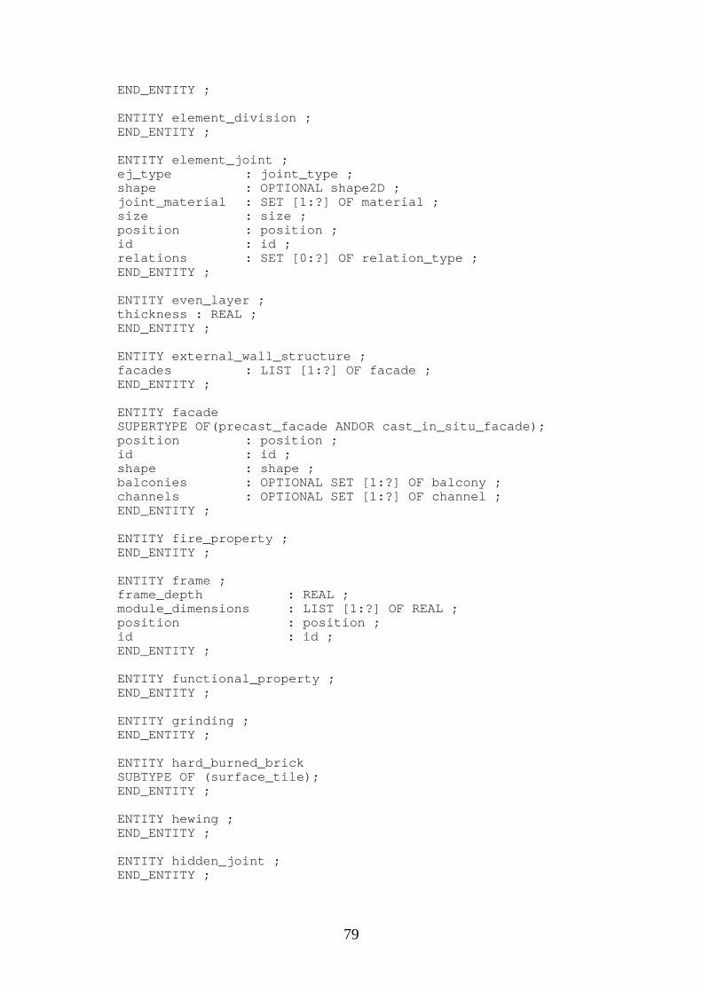
79
END_ENTITY ;
ENTITY element_division ;END_ENTITY ;
ENTITY element_joint ;ej_type : joint_type ;shape : OPTIONAL shape2D ;joint_material : SET [1:?] OF material ;size : size ;position : position ;id : id ;relations : SET [0:?] OF relation_type ;END_ENTITY ;
ENTITY even_layer ;thickness : REAL ;END_ENTITY ;
ENTITY external_wall_structure ;facades : LIST [1:?] OF facade ;END_ENTITY ;
ENTITY facadeSUPERTYPE OF(precast_facade ANDOR cast_in_situ_facade);position : position ;id : id ;shape : shape ;balconies : OPTIONAL SET [1:?] OF balcony ;channels : OPTIONAL SET [1:?] OF channel ;END_ENTITY ;
ENTITY fire_property ;END_ENTITY ;
ENTITY frame ;frame_depth : REAL ;module_dimensions : LIST [1:?] OF REAL ;position : position ;id : id ;END_ENTITY ;
ENTITY functional_property ;END_ENTITY ;
ENTITY grinding ;END_ENTITY ;
ENTITY hard_burned_brickSUBTYPE OF (surface_tile);END_ENTITY ;
ENTITY hewing ;END_ENTITY ;
ENTITY hidden_joint ;END_ENTITY ;
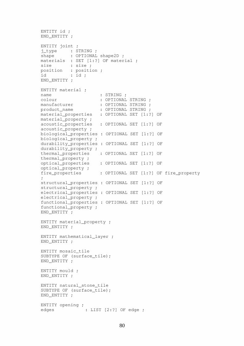
80
ENTITY id ;END_ENTITY ;
ENTITY joint ;j_type : STRING ;shape : OPTIONAL shape2D ;materials : SET [1:?] OF material ;size : size ;position : position ;id : id ;END_ENTITY ;
ENTITY material ;name : STRING ;colour : OPTIONAL STRING ;manufacturer : OPTIONAL STRING ;product_name : OPTIONAL STRING ;material_properties : OPTIONAL SET [1:?] OFmaterial_property ;acoustic_properties : OPTIONAL SET [1:?] OFacoustic_property ;biological_properties : OPTIONAL SET [1:?] OFbiological_property ;durability_properties : OPTIONAL SET [1:?] OFdurability_property ;thermal_properties : OPTIONAL SET [1:?] OFthermal_property ;optical_properties : OPTIONAL SET [1:?] OFoptical_property ;fire_properties : OPTIONAL SET [1:?] OF fire_property;structural_properties : OPTIONAL SET [1:?] OFstructural_property ;electrical_properties : OPTIONAL SET [1:?] OFelectrical_property ;functional_properties : OPTIONAL SET [1:?] OFfunctional_property ;END_ENTITY ;
ENTITY material_property ;END_ENTITY ;
ENTITY mathematical_layer ;END_ENTITY ;
ENTITY mosaic_tileSUBTYPE OF (surface_tile);END_ENTITY ;
ENTITY mould ;END_ENTITY ;
ENTITY natural_stone_tileSUBTYPE OF (surface_tile);END_ENTITY ;
ENTITY opening ;edges : LIST [2:?] OF edge ;
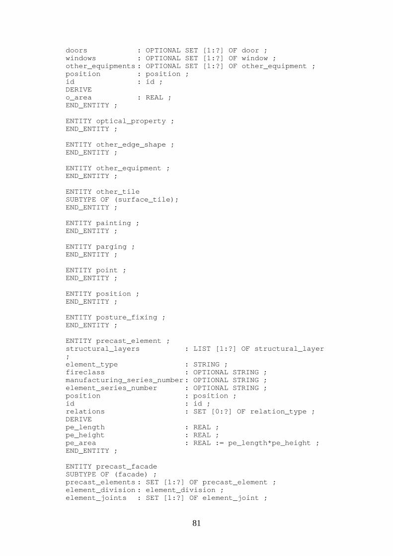
81
doors : OPTIONAL SET [1:?] OF door ;windows : OPTIONAL SET [1:?] OF window ;other_equipments : OPTIONAL SET [1:?] OF other_equipment ;position : position ;id : id ;DERIVEo_area : REAL ;END_ENTITY ;
ENTITY optical_property ;END_ENTITY ;
ENTITY other_edge_shape ;END_ENTITY ;
ENTITY other_equipment ;END_ENTITY ;
ENTITY other_tileSUBTYPE OF (surface_tile);END_ENTITY ;
ENTITY painting ;END_ENTITY ;
ENTITY parging ;END_ENTITY ;
ENTITY point ;END_ENTITY ;
ENTITY position ;END_ENTITY ;
ENTITY posture_fixing ;END_ENTITY ;
ENTITY precast_element ;structural_layers : LIST [1:?] OF structural_layer;element_type : STRING ;fireclass : OPTIONAL STRING ;manufacturing_series_number : OPTIONAL STRING ;element_series_number : OPTIONAL STRING ;position : position ;id : id ;relations : SET [0:?] OF relation_type ;DERIVEpe_length : REAL ;pe_height : REAL ;pe_area : REAL := pe_length*pe_height ;END_ENTITY ;
ENTITY precast_facadeSUBTYPE OF (facade) ;precast_elements : SET [1:?] OF precast_element ;element_division : element_division ;element_joints : SET [1:?] OF element_joint ;
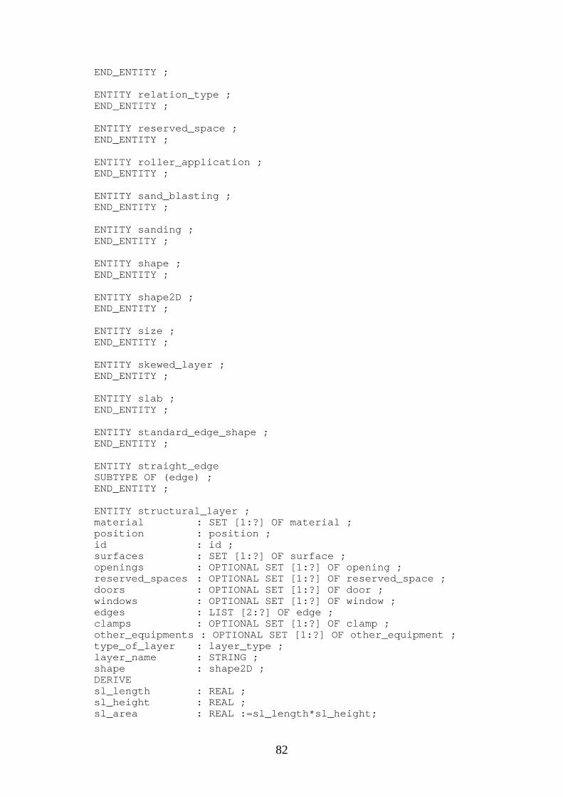
82
END_ENTITY ;
ENTITY relation_type ;END_ENTITY ;
ENTITY reserved_space ;END_ENTITY ;
ENTITY roller_application ;END_ENTITY ;
ENTITY sand_blasting ;END_ENTITY ;
ENTITY sanding ;END_ENTITY ;
ENTITY shape ;END_ENTITY ;
ENTITY shape2D ;END_ENTITY ;
ENTITY size ;END_ENTITY ;
ENTITY skewed_layer ;END_ENTITY ;
ENTITY slab ;END_ENTITY ;
ENTITY standard_edge_shape ;END_ENTITY ;
ENTITY straight_edgeSUBTYPE OF (edge) ;END_ENTITY ;
ENTITY structural_layer ;material : SET [1:?] OF material ;position : position ;id : id ;surfaces : SET [1:?] OF surface ;openings : OPTIONAL SET [1:?] OF opening ;reserved_spaces : OPTIONAL SET [1:?] OF reserved_space ;doors : OPTIONAL SET [1:?] OF door ;windows : OPTIONAL SET [1:?] OF window ;edges : LIST [2:?] OF edge ;clamps : OPTIONAL SET [1:?] OF clamp ;other_equipments : OPTIONAL SET [1:?] OF other_equipment ;type_of_layer : layer_type ;layer_name : STRING ;shape : shape2D ;DERIVEsl_length : REAL ;sl_height : REAL ;sl_area : REAL :=sl_length*sl_height;
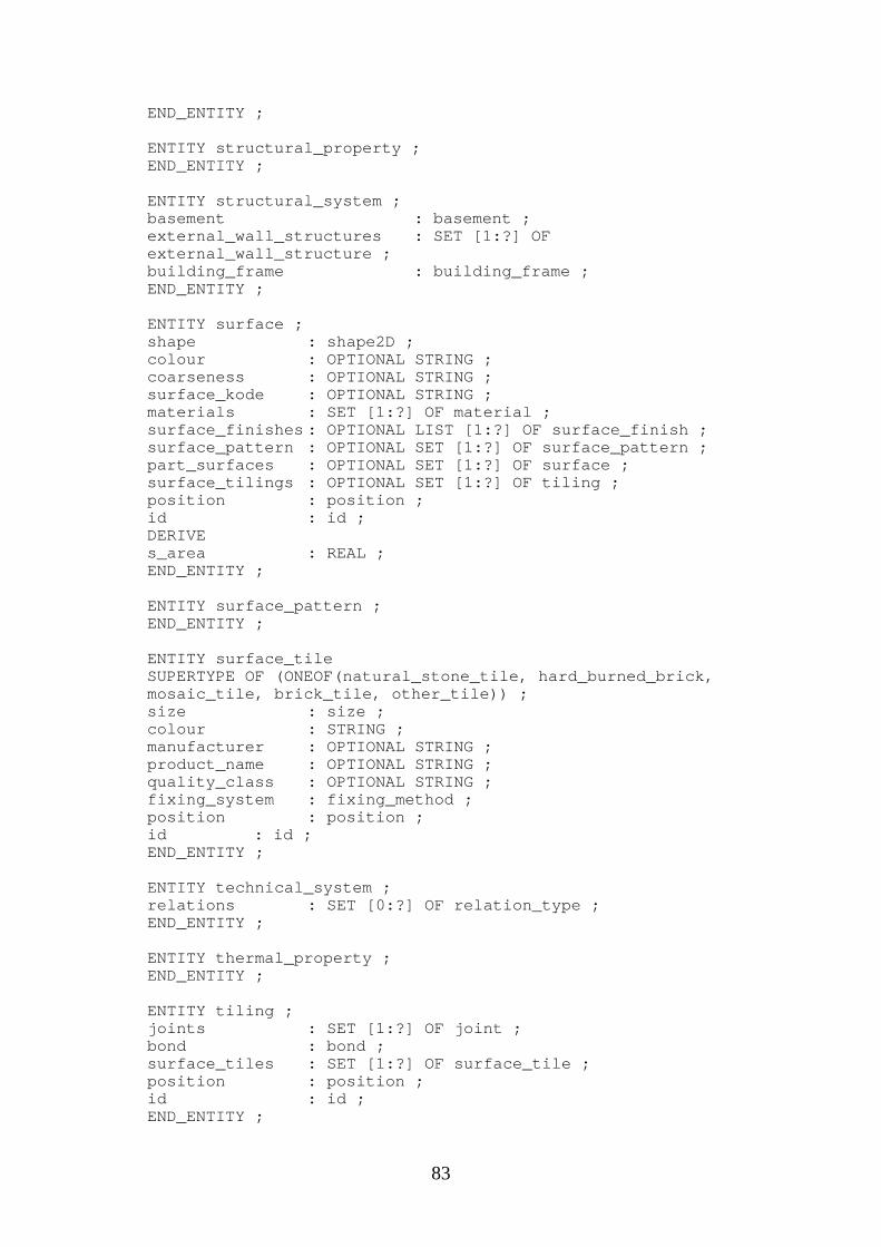
83
END_ENTITY ;
ENTITY structural_property ;END_ENTITY ;
ENTITY structural_system ;basement : basement ;external_wall_structures : SET [1:?] OFexternal_wall_structure ;building_frame : building_frame ;END_ENTITY ;
ENTITY surface ;shape : shape2D ;colour : OPTIONAL STRING ;coarseness : OPTIONAL STRING ;surface_kode : OPTIONAL STRING ;materials : SET [1:?] OF material ;surface_finishes : OPTIONAL LIST [1:?] OF surface_finish ;surface_pattern : OPTIONAL SET [1:?] OF surface_pattern ;part_surfaces : OPTIONAL SET [1:?] OF surface ;surface_tilings : OPTIONAL SET [1:?] OF tiling ;position : position ;id : id ;DERIVEs_area : REAL ;END_ENTITY ;
ENTITY surface_pattern ;END_ENTITY ;
ENTITY surface_tileSUPERTYPE OF (ONEOF(natural_stone_tile, hard_burned_brick,mosaic_tile, brick_tile, other_tile)) ;size : size ;colour : STRING ;manufacturer : OPTIONAL STRING ;product_name : OPTIONAL STRING ;quality_class : OPTIONAL STRING ;fixing_system : fixing_method ;position : position ;id : id ;END_ENTITY ;
ENTITY technical_system ;relations : SET [0:?] OF relation_type ;END_ENTITY ;
ENTITY thermal_property ;END_ENTITY ;
ENTITY tiling ;joints : SET [1:?] OF joint ;bond : bond ;surface_tiles : SET [1:?] OF surface_tile ;position : position ;id : id ;END_ENTITY ;
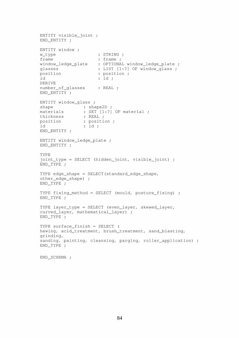
84
ENTITY visible_joint ;END_ENTITY ;
ENTITY window ;w_type : STRING ;frame : frame ;window_ledge_plate : OPTIONAL window_ledge_plate ;glasses : LIST [1:?] OF window_glass ;position : position ;id : id ;DERIVEnumber_of_glasses : REAL ;END_ENTITY ;
ENTITY window_glass ;shape : shape2D ;materials : SET [1:?] OF material ;thickness : REAL ;position : position ;id : id ;END_ENTITY ;
ENTITY window_ledge_plate ;END_ENTITY ;
TYPEjoint_type = SELECT (hidden_joint, visible_joint) ;END_TYPE ;
TYPE edge_shape = SELECT(standard_edge_shape,other_edge_shape) ;END_TYPE ;
TYPE fixing_method = SELECT (mould, posture_fixing) ;END_TYPE ;
TYPE layer_type = SELECT (even_layer, skewed_layer,curved_layer, mathematical_layer) ;END_TYPE ;
TYPE surface_finish = SELECT (hewing, acid_treatment, brush_treatment, sand_blasting,grinding,sanding, painting, cleansing, parging, roller_application) ;END_TYPE ;
END_SCHEMA ;