PRODUCT INFORMATION IN THE BOX ADDITIONAL … · 2018-10-31 · IN THE BOX • RZRXP-10 Amplified...
12
MTX.COM OWNER’S MANUAL RZRXP-10 POLARIS ® RZR ® AMPLIFIED SUBWOOFER ENCLOSURE
Transcript of PRODUCT INFORMATION IN THE BOX ADDITIONAL … · 2018-10-31 · IN THE BOX • RZRXP-10 Amplified...

M T X . C O M
OWNER’S MANUALRZRXP-10
POLARIS® RZR® AMPLIFIED SUBWOOFER ENCLOSURE

M T X . C O M2
IMPORTANT NOTICEIf you have any questions regarding wire routing in a vehicle, please contact MTX Technical Support at 1-800-225-5689.
When connecting power and ground wires ensure that the red power wire is fused at the point where it is connected to the vehicle’s battery. Failure to do so can result in damage to the vehicle if a short circuit develops between the vehicle connection point and the product.
PRODUCT INFORMATIONModel #Serial #Dealer’s NameDate of Purchase
IN THE BOX• RZRXP-10AmplifiedSubwooferEnclosure• EBCandEBCExtensionWire• Mounting Hardware (1)1"T30TorxScrew (2)1.5"T30TorxScrews
ADDITIONAL ACCESSORIES NEEDED AND NOT INCLUDEDMTX recommends using StreetWires PS1K-10 amp kit which includes the following:• PowerandGroundWiretoRuntotheBattery• 20AATCFuseHolderandFuse• AccessoryConnectionWire• RCACablestoConnecttotheSource
INSTALLATION TOOLSThe following is a list of suggested tools needed for installation:• Torx-T40• Torx-T30• Torx-T25• 10mm Wrench or Socket• Razor Knife
INTRODUCTIONThankyouforpurchasingtheMTXAudioamplifiedsubwooferenclosuredesignedforthePolaris® RZR®.TheeasytoinstallsubwooferistheperfectdirectfitbasssolutionforyourPolaris® RZR®. CongratulationsandenjoytheultimateaudioexperiencewithMTX!
FITS THE FOLLOWING VEHICLES• RZR®XP/XP41000(2014andUp)• RZR®XP/XP4TURBO(2016andUp)• RZR®900/900S/1000S(2015andUp)• RZR®4900EPS(2015andUp)NOTE:Willnotfitonvehicleswiththeaddedheateraccessory.

M T X . C O M 3
FEATURES• 10"All-WeatherAmplifiedSubwooferEnclosure• Integrated250-WattRMS/500-WattPeakPowerAmplifier• IntegratedPowerandGroundConnections• LowLevelInputwithExternalGainControl• DashMountBassControlKnob(Included)• MountsUnderneathDashboard-DirectFit,NoDrillingRequired
SPECIFICATIONS• RMS Power Handling: 250-Watts• Peak Power Handling: 500-Watts• FrequencyResponse:34Hz-120Hz

M T X . C O M4
INSTALLATIONStep 1 - Release the two quick locks to remove the hood from the vehicle.
Step 2 - Lift up the hood and slide towards the front of the vehicle.
Step3-Removethetwo(2)T40screwsholdingdownthetopdashcover.

M T X . C O M 5
Step4-Liftandpullbackthetopdashcovertoreleasetheclipsholdingitinplace.Unplugthegaugeand switches making sure not to damage the vehicle and ignition wiring. Make note to rememberwhatconnectorisassociatedwitheachspecificswitch.
Step5-RemovetheTorxheadscrewfromthedashpocketbrace.Afterthisisremovedtheplasticdash pocket and bracket can be pulled out of the dash.

M T X . C O M6
Step6-Removethetwo(2)T40screwsholdingthedashboardinplace.
Step 7 - Pull the dashboard towards the back of the vehicle. There are locking clips on the right and left side that hold it in place. The dash will pop out.
M T X . C O M 7
Step 8 - Carefullylift the dash out of the vehicle. If the locking clips have fallen off, place them back onto the locking tabs on the dash. These are needed to re-assemble the dashboard.
Step9-Removethetwo(2)10mmhexboltsthatareholdingthegloveboxtothevehicleframe.Whenthescrewsareremovedthegloveboxcanbelowereddownandoutoftheenclosure.
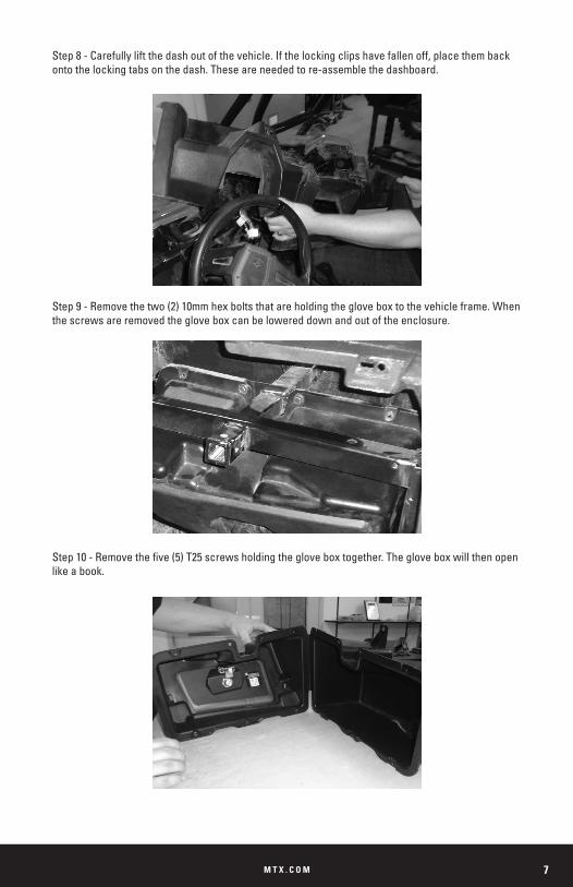
Step10-Removethefive(5)T25screwsholdingthegloveboxtogether.Thegloveboxwillthenopenlike a book.

M T X . C O M8
Step11-Cutthe“binding”plastichingewitharazorknifetoseparatethefrontandbackoftheglovebox.Thebacksideofthegloveboxwillnolongerbeused.Thefrontsideofthegloveboxwillbeattached to the enclosure.
Step12-Usingthefive(5)T25screwsthatwereremovedfromthefront/backassemblyoftheglovebox,attachthefrontofthegloveboxtotheRZRXP-10enclosure.Takecaretonotstripouttheplastic,buttightenitenoughsotheenclosureandgloveboxaresolidlyconnected.
Step 13 - The enclosure can now be placed into the vehicle. Place the rectangular protrusion at an angleintothedashareafirst.Theenclosurecantheneasilyslideupintoplace.

M T X . C O M 9
Step14-Holdtheenclosureupandalignthegloveboxscrewholeswiththevehicleframemount.Replacethetwo(2)10mmhexboltsandtightentheenclosureinplace.Itmayhelptoplaceasupportingobjectundertheenclosuresobothhandsarefreetolineupthescrewholeswiththevehicle frame mount.
Step 15 - There are three mounting holes on the bottom of the enclosure to screw the base of the enclosure into place. The furthest hole to the right uses the included 1" screw. The other two mounting holes use the 1.5" screws. Tighten the screws down, but take care to not strip them. These screws lock into the plastic foot board.

M T X . C O M10
Step 16 - Now that the enclosure is securely tightened in place, the power and signal wires need to be connected to the battery and signal source. • The Red wire should be connected directly to the battery’s positive terminal and fused with a 30A fuse. • The Blackwireshouldbedirectlyconnectedtothebattery’snegativeterminal. • If your vehicle is equipped with the Polaris®bussbarkit,theRedandBlackwirescanbe connectedtothebussbarunderthehoodonthefirewall.TheRedwirewillstillneedtobe fused. • The BluewirecanbeconnectedtotheACC/KeyTurnOnlocatedonthebussbarofanyvehicle.
Step17-ConnecttheRCAinputstothesignalsourceofyourchoice
Step 18 - Turn the unit on and check to make sure everything works. Set the gain using the gain pot that is attached to the orange / grey wires. Set the gain to the bass level desired.
Step19-TheincludedEBCcanbeconnectedandmountedtoadesiredlocationtoalloweasytrimadjustmentofthebasslevelafterthegainhasbeenset.
Step 20 - Replace all the parts and screws that have been removed to return the RZR back to its completely assembled state.

M T X . C O M 11
For proper perfomance and safety, MTX recommends installing an inline fuse per the owner’s manual instructions according to the following.
TROUBLESHOOTING
UTVThunderForm 30A Fuse
Problem Cause Solution
NoLEDIndication
No+12VatRemoteConnection Supply+12VtoTerminal
No+12VatPowerConnection Supply+12VtoTerminal
InsufficientGroundConnection VerifyGroundConnection
BlownPowerFuse
Removethe6TorxScrewsonthePerimeteroftheAmplifier.CarefullyRemovetheAmplifiertoAccesstheFuseHolderonthePowerCable.Replace with a 30A Fuse.
PowerLEDOn,NoOutput
VolumeonSourceUnitOff IncreaseVolumeonSourceUnit
GainControlonAmplifierOff TurnUpGain
IndicatorLEDSolidRed SpeakerorAmplifierDefective
OutputDistortedHeadUnitVolumeSetTooHigh LowerHeadUnitVolume
AmplifierGainSetTooHigh LowerAmplifierGain
BassisWeak SpeakersWiredOutofPhaseFromthe Subwoofer WireSpeakerswithCorrectPhase
BlowingFusesExcessiveOutputLevels LowertheVolume
AmplifierDefective Return for Service

M T X . C O M12
© 2016 Mitek Corporation. All rights reserved. MTX is a trademark of Mitek Corporation. All other trademarks are property of their respective owners. Designed and Engineered in the U.S.A.
Due to continual product development, all specifications are subject to change without notice.
MTX Audio, 4545 East Baseline Rd. Phoenix, AZ 85042 U.S.A. 1-800-225-5689
MTX005491 RevC 9/17 • 21A10545 • AW0015387