Product Guide REF615 Feeder Protection and Control · outgoing feeder. Feeder Protection and...
96
— RELION® 615 SERIES Feeder Protection and Control REF615 Product Guide
Transcript of Product Guide REF615 Feeder Protection and Control · outgoing feeder. Feeder Protection and...

—RELION® 615 SERIES
Feeder Protection and ControlREF615Product Guide
Contents
1. Description..................................................................... 3
2. Standard configurations................................................. 3
3. Protection functions......................................................20
4. Application................................................................... 20
5. Supported ABB solutions............................................. 29
6. Control......................................................................... 30
7. Measurements............................................................. 31
8. Power quality................................................................31
9. Fault location................................................................31
10. Disturbance recorder...................................................31
11. Event log..................................................................... 31
12. Recorded data............................................................ 32
13. Condition monitoring .................................................. 32
14. Trip-circuit supervision.................................................33
15. Self-supervision...........................................................33
16. Fuse failure supervision............................................... 33
17. Current circuit supervision........................................... 33
18. Access control............................................................ 33
19. Inputs and outputs...................................................... 33
20. Station communication................................................35
21. Technical data.............................................................40
22. Local HMI....................................................................77
23. Mounting methods...................................................... 78
24. Relay case and plug-in unit......................................... 78
25. Selection and ordering data.........................................78
26. Accessories and ordering data.................................... 79
27. Tools...........................................................................80
28. Cyber security............................................................. 81
29. Terminal diagrams.......................................................82
30. Certificates.................................................................. 88
31. Inspection reports....................................................... 88
32. References..................................................................88
33. Functions, codes and symbols.................................... 89
34. Document revision history........................................... 94
Disclaimer
The information in this document is subject to change without notice and should not be construed as a commitment by ABB. ABB assumes no responsibility for any errors
that may appear in this document.
© Copyright 2018 ABB.
All rights reserved.
Trademarks
ABB and Relion are registered trademarks of the ABB Group. All other brand or product names mentioned in this document may be trademarks or registered trademarks
of their respective holders.
Feeder Protection and Control 1MRS756379 TREF615 Product version: 5.0 FP1
2 ABB

1. DescriptionREF615 is a dedicated feeder protection and control relaydesigned for the protection, control, measurement andsupervision of utility substations and industrial power systemsincluding radial, looped and meshed distribution networks withor without distributed power generation. REF615 is a member
of ABB’s Relion® product family and part of its 615 protectionand control product series. The 615 series relays arecharacterized by their compactness and withdrawable-unitdesign.
Re-engineered from the ground up, the 615 series has beendesigned to unleash the full potential of the IEC 61850 standardfor communication and interoperability between substationautomation devices.
The relay provides main protection for overhead lines and cablefeeders in distribution networks. The relay is also used as back-up protection in applications, where an independent andredundant protection system is required.
Depending on the chosen standard configuration, the relay isadapted for the protection of overhead line and cable feeders inisolated neutral, resistance earthed, compensated and solidlyearthed networks. Once the standard configuration relay hasbeen given the application-specific settings, it can directly beput into service.
The 615 series relays support a range of communicationprotocols including IEC 61850 with Edition 2 support, processbus according to IEC 61850-9-2 LE, IEC 60870-5-103,
Modbus® and DNP3. Profibus DPV1 communication protocol issupported by using the protocol converter SPA-ZC 302.
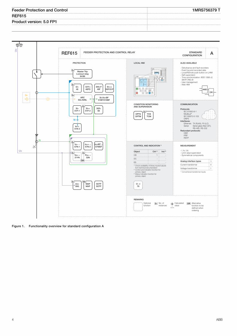
2. Standard configurationsREF615 is available with twelve alternative standardconfigurations. The standard signal configuration can bealtered by means of the signal matrix or the graphicalapplication functionality of the Protection and Control IEDManager PCM600. Further, the application configurationfunctionality of PCM600 supports the creation of multi-layerlogic functions using various logical elements, including timersand flip-flops. By combining protection functions with logicfunction blocks, the relay configuration can be adapted to user-specific application requirements.
The relay is delivered from the factory with default connectionsdescribed in the functional diagrams for binary inputs, binaryoutputs, function-to-function connections and alarm LEDs.Some of the supported functions in REF615 must be addedwith the Application Configuration tool to be available in theSignal Matrix tool and in the relay. The positive measuringdirection of directional protection functions is towards theoutgoing feeder.
Feeder Protection and Control 1MRS756379 TREF615 Product version: 5.0 FP1 Issued: 2018-12-20
Revision: T
ABB 3
CONDITION MONITORING AND SUPERVISION
ORAND
CONTROL AND INDICATION 1) MEASUREMENT
FEEDER PROTECTION AND CONTROL RELAY STANDARD CONFIGURATION
PROTECTION LOCAL HMI
Object Ctrl 2) Ind 3)
CB
DC
ES1) Check availability of binary inputs/outputs
from technical documentation2) Control and indication function for
primary object3) Status indication function for primary object
RL
ClearESCI
O
Configuration ASystemHMITimeAuthorization
RL
ClearESCI
O
U12 0. 0 kVP 0.00 kWQ 0.00 kVAr
IL2 0 A
A
REMARKS
Optionalfunction
No. ofinstances
Alternative function to be defined when ordering
OR
Io/Uo
Calculatedvalue
3×
COMMUNICATION
Protocols: IEC 61850-8-1 Modbus®
IEC 60870-5-103 DNP3Interfaces: Ethernet: TX (RJ45), FX (LC) Serial: Serial glass fiber (ST), RS-485, RS-232Redundant protocols: HSR PRP RSTP
REF615
1 -
- -
- -
- I, Io, Uo- Limit value supervision- Symmetrical components
4
1
Analog interface types 1)
Current transformer
Voltage transformer1) Conventional transformer inputs
ALSO AVAILABLE
- Disturbance and fault recorders- Event log and recorded data- Local/Remote push button on LHMI- Self-supervision- Time synchronization: IEEE 1588 v2,
SNTP, IRIG-B- User management- Web HMI
2×TCSTCM
O→I79
2×I2>46
I2/I1>46PD
3Ith>F49F
3I>>>50P/51P
3×ARC
50L/50NL
2×Master Trip
Lockout relay94/86
2×Io>→67N-1
Io>>→67N-2
Io>IEF→67NIEF
3×Uo>59G
Io>>51N-2
3I>51P-1
3I>/Io>BF51BF/51NBF
3I2f>68
3×Yo>→21YN
3×Po>→32N
OR
2×3I>>
51P-2
OPTSOPTM
18×MAPMAP
Uo
Uo
Io
Io
3×
A
SOTFSOTF
GUID-030C217F-7B91-4739-9DAE-90D1E053EB53 V2 EN
Figure 1. Functionality overview for standard configuration A
Feeder Protection and Control 1MRS756379 TREF615 Product version: 5.0 FP1
4 ABB
CONDITION MONITORING AND SUPERVISION
ORAND
CONTROL AND INDICATION 1) MEASUREMENT
FEEDER PROTECTION AND CONTROL RELAY STANDARD CONFIGURATION
PROTECTION LOCAL HMI
Object Ctrl 2) Ind 3)
CB
DC
ES1) Check availability of binary inputs/outputs
from technical documentation2) Control and indication function for
primary object3) Status indication function for primary object
RL
ClearESCI
O
Configuration ASystemHMITimeAuthorization
RL
ClearESCI
O
U12 0. 0 kVP 0.00 kWQ 0.00 kVAr
IL2 0 A
A
REMARKS
Optionalfunction
No. ofinstances
Alternative function to be defined when ordering
OR
Io/Uo
Calculatedvalue
3×
COMMUNICATION
Protocols: IEC 61850-8-1 Modbus®
IEC 60870-5-103 DNP3Interfaces: Ethernet: TX (RJ45), FX (LC) Serial: Serial glass fiber (ST), RS-485, RS-232Redundant protocols: HSR PRP RSTP
REF615
1 -
2 3
1 2
B
- I, Io, Uo- Limit value supervision- Load profile record- RTD/mA measurement (optional)- Symmetrical components
4
1
Analog interface types 1)
Current transformer
Voltage transformer1) Conventional transformer inputs
ALSO AVAILABLE
- Disturbance and fault recorders- Event log and recorded data- High-Speed Output module (optional)- Local/Remote push button on LHMI- Self-supervision- Time synchronization: IEEE 1588 v2,
SNTP, IRIG-B- User management- Web HMI
2×TCSTCM
O→I79
2×I2>46
I2/I1>46PD
3Ith>F49F
3I>>>50P/51P
3×ARC
50L/50NL
Master TripLockout relay
94/86
2×Io>→67N-1
Io>>→67N-2
Io>IEF→67NIEF
3×Uo>59G
3I>/Io>BF51BF/51NBF
3I2f>68
3I>51P-1
2×3I>>
51P-2
CBCMCBCM
3×Yo>→21YN
3×Po>→32N
Io>HA51NHA
OR OR
OPTSOPTM
PHIZHIZ
18×MAPMAP
6xRTD2xmA
Io>>51N-2
Uo
Io
Uo
3I
Io
3×
SOTFSOTF
Master TripLockout relay
94/86
3×2×
GUID-5E9640AA-129C-42CB-9E29-5480A9656B10 V2 EN
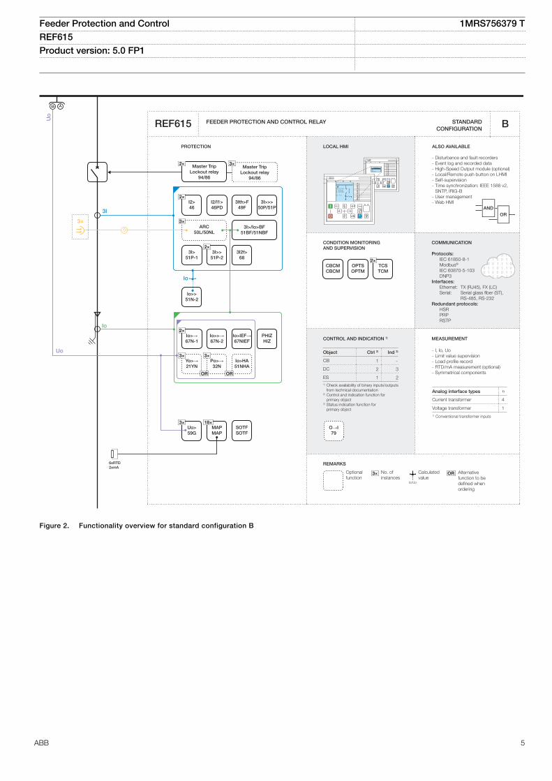
Figure 2. Functionality overview for standard configuration B
Feeder Protection and Control 1MRS756379 TREF615 Product version: 5.0 FP1
ABB 5
CONDITION MONITORING AND SUPERVISION
ORAND
CONTROL AND INDICATION 1) MEASUREMENT
FEEDER PROTECTION AND CONTROL RELAY STANDARD CONFIGURATION
PROTECTION LOCAL HMI
Object Ctrl 2) Ind 3)
CB
DC
ES1) Check availability of binary inputs/outputs
from technical documentation2) Control and indication function for
primary object3) Status indication function for primary object
RL
ClearESCI
O
Configuration ASystemHMITimeAuthorization
RL
ClearESCI
O
U12 0. 0 kVP 0.00 kWQ 0.00 kVAr
IL2 0 A
A
REMARKS
Optionalfunction
No. ofinstances
Alternative function to be defined when ordering
OR
Io/Uo
Calculatedvalue
3×
COMMUNICATION
Protocols: IEC 61850-8-1 Modbus®
IEC 60870-5-103 DNP3Interfaces: Ethernet: TX (RJ45), FX (LC) Serial: Serial glass fiber (ST), RS-485, RS-232Redundant protocols: HSR PRP RSTP
REF615
1 -
- -
- -
C
- I, Io- Limit value supervision- Symmetrical components
4
-
Analog interface types 1)
Current transformer
Voltage transformer1) Conventional transformer inputs
2×TCSTCM
O→I79
2×I2>46
I2/I1>46PD
3Ith>F49F
3I>>>50P/51P
3×ARC
50L/50NL
2×Master Trip
Lockout relay94/86
3I>/Io>BF51BF/51NBF
3I2f>68
3I>51P-1
2×3I>>
51P-2
Io>>51N-2
Io>>>50N/51N
2×Io>
51N-1
OPTSOPTM
18×MAPMAP
3I
Io
3×
ALSO AVAILABLE
- Disturbance and fault recorders- Event log and recorded data- Local/Remote push button on LHMI- Self-supervision- Time synchronization: IEEE 1588 v2,
SNTP, IRIG-B- User management- Web HMI
SOTFSOTF
GUID-5404DAD5-4FE4-4E91-8A18-31CC0812A09C V2 EN
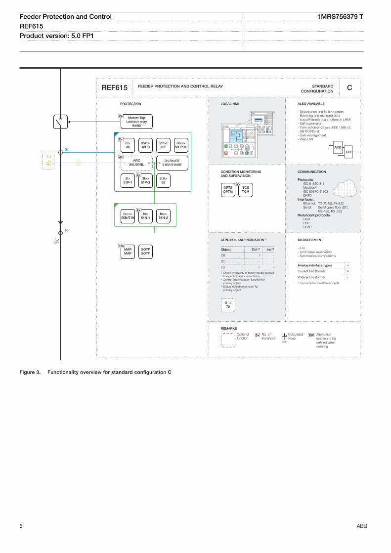
Figure 3. Functionality overview for standard configuration C
Feeder Protection and Control 1MRS756379 TREF615 Product version: 5.0 FP1
6 ABB
CONDITION MONITORING AND SUPERVISION
ORAND
CONTROL AND INDICATION 1) MEASUREMENT
FEEDER PROTECTION AND CONTROL RELAY STANDARD CONFIGURATION
PROTECTION LOCAL HMI
Object Ctrl 2) Ind 3)
CB
DC
ES1) Check availability of binary inputs/outputs
from technical documentation2) Control and indication function for
primary object3) Status indication function for primary object
RL
ClearESCI
O
Configuration ASystemHMITimeAuthorization
RL
ClearESCI
O
U12 0. 0 kVP 0.00 kWQ 0.00 kVAr
IL2 0 A
A
REMARKS
Optionalfunction
No. ofinstances
Alternative function to be defined when ordering
OR
Io/Uo
Calculatedvalue
3×
COMMUNICATION
Protocols: IEC 61850-8-1 Modbus®
IEC 60870-5-103 DNP3Interfaces: Ethernet: TX (RJ45), FX (LC) Serial: Serial glass fiber (ST), RS-485, RS-232Redundant protocols: HSR PRP RSTP
REF615 D
- I, Io- Limit value supervision- Load profile record- RTD/mA measurement (optional)- Symmetrical components
4
-
Analog interface types 1)
Current transformer
Voltage transformer1) Conventional transformer inputs
OPTSOPTM
2×TCSTCM
O→I79
2×I2>46
I2/I1>46PD
3Ith>F49F
3I>>>50P/51P
3×ARC
50L/50NL
Io>>51N-2
3I>51P-1
3I>/Io>BF51BF/51NBF
3I2f>68
2×3I>>
51P-2
CBCMCBCM
Io>>>50N/51N
2×Io>
51N-1Io>HA51NHA
2×Master Trip
Lockout relay94/86
18×MAPMAP
3I
Io
3×
1 -
2 3
1 2
ALSO AVAILABLE
- Disturbance and fault recorders- Event log and recorded data- High-Speed Output module (optional)- Local/Remote push button on LHMI- Self-supervision- Time synchronization: IEEE 1588 v2,
SNTP, IRIG-B- User management- Web HMI
SOTFSOTF
GUID-2907E142-1D1E-4109-9603-76FDF7A15F02 V2 EN
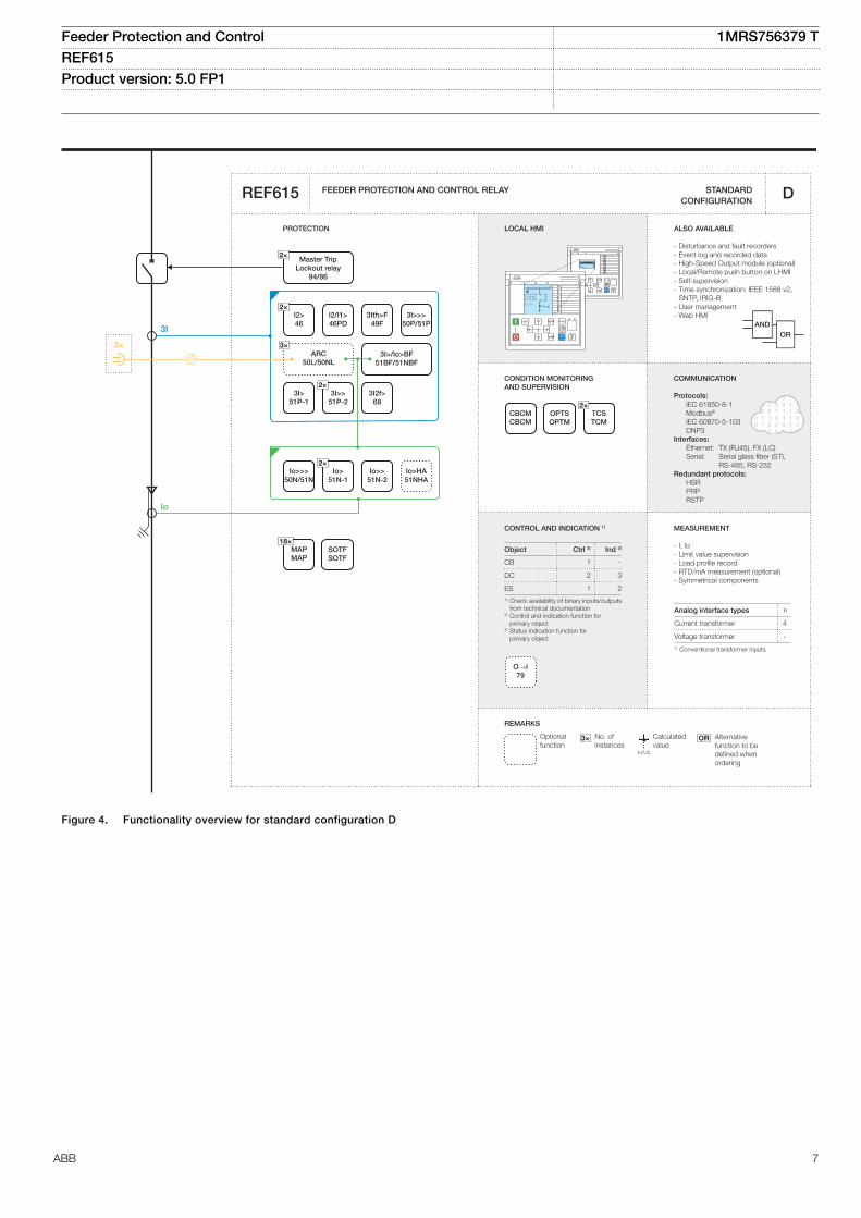
Figure 4. Functionality overview for standard configuration D
Feeder Protection and Control 1MRS756379 TREF615 Product version: 5.0 FP1
ABB 7
CONDITION MONITORING AND SUPERVISION
ORAND
CONTROL AND INDICATION 1) MEASUREMENT
FEEDER PROTECTION AND CONTROL RELAY STANDARD CONFIGURATION
PROTECTION LOCAL HMI
Object Ctrl 2) Ind 3)
CB
DC
ES1) Check availability of binary inputs/outputs
from technical documentation2) Control and indication function for
primary object3) Status indication function for primary object
RL
ClearESCI
O
Configuration ASystemHMITimeAuthorization
RL
ClearESCI
O
U12 0. 0 kVP 0.00 kWQ 0.00 kVAr
IL2 0 A
A
REMARKS
Optionalfunction
No. ofinstances
Alternative function to be defined when ordering
OR
Io/Uo
Calculatedvalue
3×
REF615
COMMUNICATION
Protocols: IEC 61850-8-1/-9-2LE Modbus®
IEC 60870-5-103 DNP3Interfaces: Ethernet: TX (RJ45), FX (LC) Serial: Serial glass fiber (ST), RS-485, RS-232Redundant protocols: HSR PRP RSTP
1 -
2 3
1 2
E
- I, U, Io, Uo, P, Q, E, pf, f- Limit value supervision- Load profile record- RTD/mA measurement (optional)- Symmetrical components
4
5
Analog interface types 1)
Current transformer
Voltage transformer1) Conventional transformer inputs
FUSEF60
CBCMCBCM
MCS 3IMCS 3I
O→I79
2×I2>46
I2/I1>46PD
3Ith>F49F
3I>>>50P/51P
3×ARC
50L/50NL
Master TripLockout relay
94/86
2×Io>→67N-1
Io>>→67N-2
Io>IEF→67NIEF
3×Yo>→21YN
3×Po>→32N
3I>/Io>BF51BF/51NBF
3I2f>68
OR
3I>51P-1
2×3I>>
51P-2
3×Uo>59G
2×TCSTCM
OPTSOPTM
18×MAPMAP
2xRTD1xmA
PHIZHIZ
Io>>51N-2
3I
3I
UL1
UL2
UL3
UL1UL2UL3
Uo
Uo
Io
Io Io
Io
3×
ALSO AVAILABLE
- Disturbance and fault recorders- Event log and recorded data- High-Speed Output module (optional)- Local/Remote push button on LHMI- Self-supervision- Time synchronization: IEEE 1588 v2,
SNTP, IRIG-B- User management- Web HMI
SOTFSOTF
Master TripLockout relay
94/86
3×2×
GUID-4512CC4D-BAA4-49CD-BF84-7BA9628DC231 V2 EN
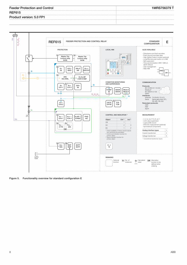
Figure 5. Functionality overview for standard configuration E
Feeder Protection and Control 1MRS756379 TREF615 Product version: 5.0 FP1
8 ABB
CONDITION MONITORING AND SUPERVISION
ORAND
CONTROL AND INDICATION 1) MEASUREMENT
FEEDER PROTECTION AND CONTROL RELAY STANDARD CONFIGURATION
PROTECTION LOCAL HMI
Object Ctrl 2) Ind 3)
CB
DC
ES1) Check availability of binary inputs/outputs
from technical documentation2) Control and indication function for
primary object3) Status indication function for primary object
RL
ClearESCI
O
Configuration ASystemHMITimeAuthorization
RL
ClearESCI
O
U12 0. 0 kVP 0.00 kWQ 0.00 kVAr
IL2 0 A
A
REMARKS
Optionalfunction
No. ofinstances
Alternative function to be defined when ordering
OR
Io/Uo
Calculatedvalue
3×
REF615
COMMUNICATION
Protocols: IEC 61850-8-1/-9-2LE Modbus®
IEC 60870-5-103 DNP3Interfaces: Ethernet: TX (RJ45), FX (LC) Serial: Serial glass fiber (ST), RS-485, RS-232Redundant protocols: HSR PRP RSTP
1 -
2 3
1 2
F
- I, U, Io, Uo, P, Q, E, pf, f- Limit value supervision- Load profile record- RTD/mA measurement (optional)- Symmetrical components
4
5
Analog interface types 1)
Current transformer
Voltage transformer1) Conventional transformer inputs
ALSO AVAILABLE
- Disturbance and fault recorders- Event log and recorded data- High-Speed Output module (optional)- Local/Remote push button on LHMI- Self-supervision- Time synchronization: IEEE 1588 v2,
SNTP, IRIG-B- User management- Web HMI
2×3I>→67-1
O→I79
2×I2>46
I2/I1>46PD
3Ith>F49F
3I>>>50P/51P
3×ARC
50L/50NL
Master TripLockout relay
94/86
2×Io>→67N-1
Io>>→67N-2
Io>IEF→67NIEF
3×Yo>→21YN
3×Po>→32N
Io>HA51NHA
3×3U<27
U2>47O-
U1<47U+
3×3U>59
3×Uo>59G
3I>>→67-2
3I>/Io>BF51BF/51NBF
3I2f>68
OR OR
MCS 3IMCS 3I
FUSEF60
CBCMCBCM
2×TCSTCM
OPTSOPTM
18×MAPMAP
2xRTD1xmA
PHIZHIZ
Io>>51N-2
3I
UL1UL2UL3
Uo
Io
Io
UL1UL2UL3
UL1
UL2
UL3
Uo
3I
3×
Io
SOTFSOTF
Master TripLockout relay
94/86
3×2×
GUID-6130FC3E-1C25-479D-B922-BA263933D048 V2 EN
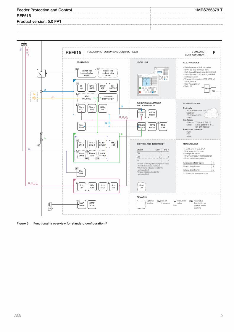
Figure 6. Functionality overview for standard configuration F
Feeder Protection and Control 1MRS756379 TREF615 Product version: 5.0 FP1
ABB 9
CONDITION MONITORING AND SUPERVISION
ORAND
FEEDER PROTECTION AND CONTROL RELAY STANDARD CONFIGURATION
PROTECTION LOCAL HMI
RL
ClearESCI
O
Configuration ASystemHMITimeAuthorization
RL
ClearESCI
O
U12 0. 0 kVP 0.00 kWQ 0.00 kVAr
IL2 0 A
A
REMARKS
Optionalfunction
No. ofinstances
Alternative function to be defined when ordering
OR
Io/Uo
Calculatedvalue
3×
REF615
COMMUNICATION
Protocols: IEC 61850-8-1 IEC 61850-9-2LE Modbus®
IEC 60870-5-103 DNP3Interfaces: Ethernet: TX (RJ45), FX (LC) Serial: Serial glass fiber (ST), RS-485, RS-232Redundant protocols: HSR PRP RSTP
G
ALSO AVAILABLE
- Disturbance and fault recorders- Event log and recorded data- High-Speed Output module (optional)- Local/Remote push button on LHMI- Self-supervision- Time synchronization: IEEE 1588 v2,
SNTP, IRIG-B- User management- Web HMI
MEASUREMENT
- I, U, Io, Uo, P, Q, E, pf, f- Limit value supervision- Load profile record- Symmetrical components
Analog interface types 1)
Current sensor 3
Voltage sensor 3
Current transformer 11) Combi sensor inputs with conventional
Io input
CONTROL AND INDICATION 1)
Object Ctrl 2) Ind 3)
CB
DC
ES1) Check availability of binary inputs/outputs
from technical documentation2) Control and indication function for
primary object3) Status indication function for primary object
1 -
2 3
1 2
2×3I>→67-1
O→I79
2×I2>46
I2/I1>46PD
3Ith>F49F
3I>>>50P/51P
3×ARC
50L/50NL
Master TripLockout relay
94/86
2×Io>→67N-1
Io>>→67N-2
3×Yo>→21YN
3×Po>→32N
3×3U<27
U2>47O-
U1<47U+
3×3U>59
3×Uo>59G
Io>>51N-2
3I>>→67-2
3I>/Io>BF51BF/51NBF
3I2f>68
OR
MCS 3IMCS 3I
FUSEF60
CBCMCBCM
2×TCSTCM
OPTSOPTM
PHIZHIZ
18×MAPMAP
SYNC25
UL1
UL2
UL3
3I
Io
Uo
Io
3I
Io
UL1UL2UL3
3×
IEC 61850-9-2LE
SOTFSOTF
UL1UL2UL3
UL1
Master TripLockout relay
94/86
3×2×
GUID-3524788E-FDB0-4425-9949-C5CBD1301E75 V2 EN
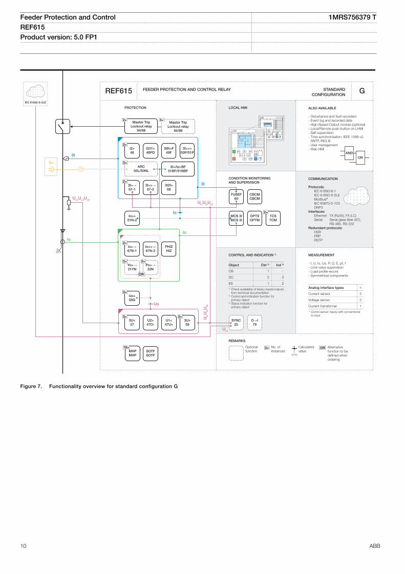
Figure 7. Functionality overview for standard configuration G
Feeder Protection and Control 1MRS756379 TREF615 Product version: 5.0 FP1
10 ABB
CONDITION MONITORING AND SUPERVISION
ORAND
CONTROL AND INDICATION 1) MEASUREMENT
FEEDER PROTECTION AND CONTROL RELAY STANDARD CONFIGURATION
PROTECTION LOCAL HMI
Object Ctrl 2) Ind 3)
CB
DC
ES1) Check availability of binary inputs/outputs
from technical documentation2) Control and indication function for
primary object3) Status indication function for primary object
RL
ClearESCI
O
Configuration ASystemHMITimeAuthorization
RL
ClearESCI
O
U12 0. 0 kVP 0.00 kWQ 0.00 kVAr
IL2 0 A
A
REMARKS
Optionalfunction
No. ofinstances
Alternative function to be defined when ordering
OR
Io/Uo
Calculatedvalue
3×
REF615
COMMUNICATION
Protocols: IEC 61850-8-1/-9-2LE Modbus®
IEC 60870-5-103 DNP3Interfaces: Ethernet: TX (RJ45), FX (LC) Serial: Serial glass fiber (ST), RS-485, RS-232Redundant protocols: HSR PRP RSTP
H
- I, U, Io, Uo, P, Q, E, pf, f- Limit value supervision- Load profile record- RTD/mA measurement (optional)- Symmetrical components
4
5
Analog interface types 1)
Current transformer
Voltage transformer1) Conventional transformer inputs
ALSO AVAILABLE
- Disturbance and fault recorders- Event log and recorded data- High-Speed Output module (optional)- Local/Remote push button on LHMI- Self-supervision- Time synchronization: IEEE 1588 v2,
SNTP, IRIG-B- User management- Web HMI
1 -
2 3
1 2
3I>51P-1
2×3I>>
51P-2
SYNC25
O→I79
2×I2>46
I2/I1>46PD
3I>>>50P/51P
3×ARC
50L/50NL
Master TripLockout relay
94/86
3×3U<27
3×3U>59
3×Uo>59G
3×f>/f<,df/dt81
Io>>51N-2
3I>/Io>BF51BF/51NBF
3I2f>68
Io>>>50N/51N
2xRTD1xmA
MCS 3IMCS 3I
FUSEF60
CBCMCBCM
2×TCSTCM
OPTSOPTM
18×MAPMAP
PHIZHIZ
2×Io>
51N-1
3I
UL1
UL2
UL3
UL1UL2UL3 UL1
UL2
UL3
U12
U12
Uo
Uo
Io
Io
IoIo
3I
3×
SOTFSOTF
Master TripLockout relay
94/86
3×2×
GUID-345574F5-1790-43CF-BCD8-FE2C4EFF1CE5 V2 EN
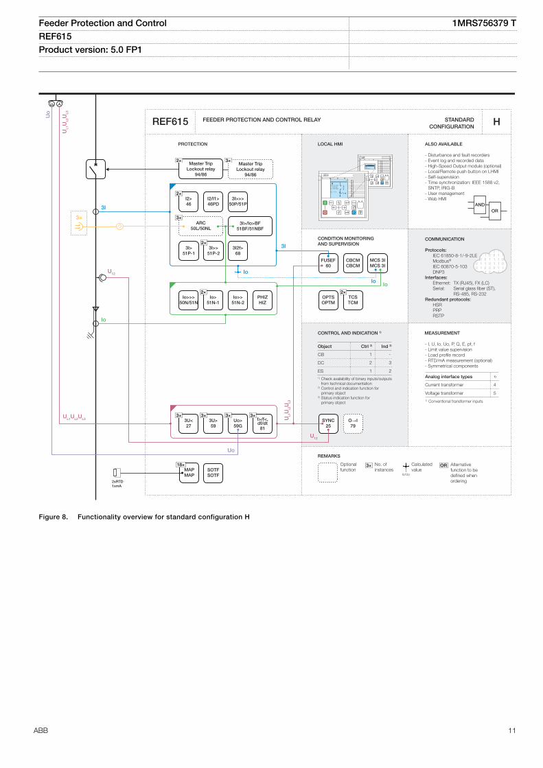
Figure 8. Functionality overview for standard configuration H
Feeder Protection and Control 1MRS756379 TREF615 Product version: 5.0 FP1
ABB 11
CONDITION MONITORING AND SUPERVISION
ORAND
CONTROL AND INDICATION 1) MEASUREMENT
FEEDER PROTECTION AND CONTROL RELAY STANDARD CONFIGURATION
PROTECTION LOCAL HMI
Object Ctrl 2) Ind 3)
CB
DC
ES1) Check availability of binary inputs/outputs
from technical documentation2) Control and indication function for
primary object3) Status indication function for primary object
RL
ClearESCI
O
Configuration ASystemHMITimeAuthorization
RL
ClearESCI
O
U12 0. 0 kVP 0.00 kWQ 0.00 kVAr
IL2 0 A
A
REMARKS
Optionalfunction
No. ofinstances
Alternative function to be defined when ordering
OR
Io/Uo
Calculatedvalue
3×
REF615
COMMUNICATION
Protocols: IEC 61850-8-1/-9-2LE Modbus®
IEC 60870-5-103 DNP3Interfaces: Ethernet: TX (RJ45), FX (LC) Serial: Serial glass fiber (ST), RS-485, RS-232Redundant protocols: HSR PRP RSTP
J
- I, U, Io, Uo, P, Q, E, pf, f- Limit value supervision- Load profile record- RTD/mA measurement (optional)- Symmetrical components
4
5
Analog interface types 1)
Current transformer
Voltage transformer1) Conventional transformer inputs
ALSO AVAILABLE
- Disturbance and fault recorders- Event log and recorded data- High-Speed Output module (optional)- Local/Remote push button on LHMI- Self-supervision- Time synchronization: IEEE 1588 v2,
SNTP, IRIG-B- User management- Web HMI
1 -
2 3
1 2
SYNC25
O→I79
2×I2>46
3Ith>F49F
3I>>>50P/51P
3×ARC
50L/50NL
Master TripLockout relay
94/86
2×Io>→67N-1
Io>>→67N-2
Io>IEF→67NIEF
3×Yo>→21YN
3×Po>→32N
Io>HA51NHA
3×3U<27
U2>47O-
U1<47U+
3×3U>59
3×Uo>59G
3×f>/f<,df/dt81
2×3I>→67-1
3I>>→67-2
3I>/Io>BF51BF/51NBF
3I2f>68
PQM3IPQM3I
PQM3UPQM3V
PQMUPQMV
OR OR
I2/I1>46PD
18×MAPMAP
Io>>51N-2
2xRTD1xmA
MCS 3IMCS 3I
FUSEF60
CBCMCBCM
2×TCSTCM
OPTSOPTM
3I
UL1UL2UL3
U12
U12
Uo
Io
Io
UL1
UL2
UL3
Uo
3I
Io
UL1UL2UL3
PQUUBPQVUB
3×
UL1
UL2
UL3
SOTFSOTF
Master TripLockout relay
94/86
3×2×
GUID-8736C89A-53BA-49B3-95A1-3984B605504F V2 EN
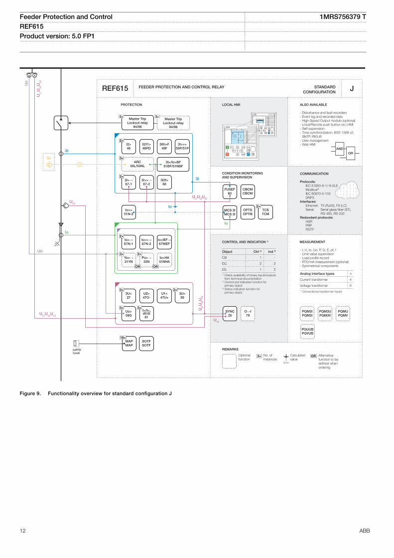
Figure 9. Functionality overview for standard configuration J
Feeder Protection and Control 1MRS756379 TREF615 Product version: 5.0 FP1
12 ABB
CONDITION MONITORING AND SUPERVISION
ORAND
CONTROL AND INDICATION 1) MEASUREMENT
FEEDER PROTECTION AND CONTROL RELAY STANDARD CONFIGURATION
PROTECTION LOCAL HMI
Object Ctrl 2) Ind 3)
CB
DC
ES1) Check availability of binary inputs/outputs
from technical documentation2) Control and indication function for
primary object3) Status indication function for primary object
RL
ClearESCI
O
Configuration ASystemHMITimeAuthorization
RL
ClearESCI
O
U12 0. 0 kVP 0.00 kWQ 0.00 kVAr
IL2 0 A
A
REMARKS
Optionalfunction
No. ofinstances
Alternative function to be defined when ordering
OR
Io/Uo
Calculatedvalue
3×
REF615
COMMUNICATION
Protocols: IEC 61850-8-1/-9-2LE Modbus®
IEC 60870-5-103 DNP3Interfaces: Ethernet: TX (RJ45), FX (LC) Serial: Serial glass fiber (ST), RS-485, RS-232Redundant protocols: HSR PRP RSTP
PQUUBPQVUB
K
- I, U, Io, Uo, P, Q, E, pf, f- Limit value supervision- Load profile record- Symmetrical components
5
5
Analog interface types 1)
Current transformer
Voltage transformer1) Conventional transformer inputs
ALSO AVAILABLE
- Disturbance and fault recorders- Event log and recorded data- High-Speed Output module (optional)- Local/Remote push button on LHMI- Self-supervision- Time synchronization: IEEE 1588 v2,
SNTP, IRIG-B- User management- Web HMI
1 -
2 3
1 2
3I>51P-1
3I>>51P-2
SYNC25
O→I79
2×I2>46
3I>>>50P/51P
3×ARC
50L/50NL
Master TripLockout relay
94/86
Master TripLockout relay
94/86
3×2×
2×3U<27
2×3U>59
2×Uo>59G
3×f>/f<,df/dt81
3I>/Io>BF51BF/51NBF
3I2f>68
Io>>>50N/51N
18×MAPMAP
2×TCSTCM
MCS 3IMCS 3I
FUSEF60
CBCMCBCM
OPTSOPTM
3I>→67-1
3I>>→67-2
dIoHi>87NH
3Ith>F49F
PQM3IPQM3I
PQM3UPQM3V
PQMUPQMV
Io>>51N-2
Io>→67N-1
Io>>→67N-2
FLOC21FL
2×Io>
51N-1
3I
3I
Uo
UL1
UL2
UL3
U12
U12
Io
Io
Io
Iob
UL1
UL2
UL3
Uo
3×
SOTFSOTF
GUID-8CD5AE89-755F-489F-8B47-DC1ADF541EE7 V2 EN
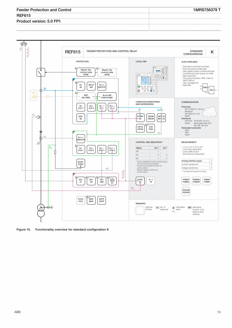
Figure 10. Functionality overview for standard configuration K
Feeder Protection and Control 1MRS756379 TREF615 Product version: 5.0 FP1
ABB 13
CONDITION MONITORING AND SUPERVISION
ORAND
FEEDER PROTECTION AND CONTROL RELAY STANDARD CONFIGURATION
PROTECTION LOCAL HMI
RL
ClearESCI
O
Configuration ASystemHMITimeAuthorization
RL
ClearESCI
O
U12 0. 0 kVP 0.00 kWQ 0.00 kVAr
IL2 0 A
A
REMARKS
Optionalfunction
No. ofinstances
Alternative function to be defined when ordering
OR
Io/Uo
Calculatedvalue
3×
REF615
COMMUNICATION
Protocols: IEC 61850-8-1 IEC 61850-9-2LE Modbus®
IEC 60870-5-103 DNP3Interfaces: Ethernet: TX (RJ45), FX (LC) Serial: Serial glass fiber (ST), RS-485, RS-232Redundant protocols: HSR PRP RSTP
L
ALSO AVAILABLE
- Disturbance and fault recorders- Event log and recorded data- High-Speed Output module (optional)- Local/Remote push button on LHMI- Self-supervision- Time synchronization: IEEE 1588 v2,
SNTP, IRIG-B- User management- Web HMI
MEASUREMENT
- I, U, Io, P, Q, E, pf, f- Limit value supervision- Load profile record- Symmetrical components
3
3
Analog interface types 1)
Current sensor
Voltage sensor
1Current transformer1) Combi sensor inputs with conventional Io
input
CONTROL AND INDICATION 1)
Object Ctrl 2) Ind 3)
CB
DC
ES1) Check availability of binary inputs/outputs
from technical documentation2) Control and indication function for
primary object3) Status indication function for primary object
1 -
2 3
1 2
O→I79
2×I2>46
3Ith>F49F
3I>>>50P/51P
3×ARC
50L/50NL
Master TripLockout relay
94/86
Master TripLockout relay
94/86
3×2×
Io>>51N-2
3I>>→67-2
3I>/Io>BF51BF/51NBF
3I2f>68
PQM3IPQM3I
PQM3UPQM3V
PQMUPQMV
MCS 3IMCS 3I
FUSEF60
CBCMCBCM
2×TCSTCM
OPTSOPTM
18×MAPMAP
FLOC21FL
I2/I1>46PD
3I>51P-1
3I>>51P-2
P>/Q>32R/32O
Q>→, 3U<32Q, 27
PQUUBPQVUB
3I>→67-1
3I
Io
3×3U<27
U2>47O-
U1<47U+
3×3U>59
3×Uo>59G
f>/f<,df/dt81
Io
Uo
IoIo
2×Io>→67N-1
Io>>→67N-2
Io>IEF→67NIEF
3×Yo>→21YN
3×Po>→32N
Io>HA51NHA
OR OR
2×U
L1U
L2U
L3
Io>51N-1
Io>>>50N/51N
Io>→Y67YN
VS78V
U<RT27RT
IEC 61850-9-2LE
3I3×
SOTFSOTF
SYNC25
2×
2×
2× 2×
6×
3×
2×
UL1
UL1UL2UL3
GUID-A240AB33-E70D-4471-A934-D2603FE3E6FE V3 EN
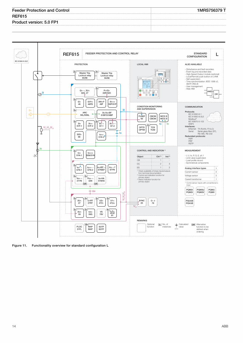
Figure 11. Functionality overview for standard configuration L
Feeder Protection and Control 1MRS756379 TREF615 Product version: 5.0 FP1
14 ABB
CONDITION MONITORING AND SUPERVISION
ORAND
CONTROL AND INDICATION 1) MEASUREMENT
FEEDER PROTECTION AND CONTROL RELAY STANDARD CONFIGURATION
PROTECTION LOCAL HMI
Object Ctrl 2) Ind 3)
CB
DC
ES1) Check availability of binary inputs/outputs
from technical documentation2) Control and indication function for
primary object3) Status indication function for primary object
RL
ClearESCI
O
Configuration ASystemHMITimeAuthorization
RL
ClearESCI
O
U12 0. 0 kVP 0.00 kWQ 0.00 kVAr
IL2 0 A
A
*
OR
REMARKS
Optionalfunction
No. ofinstances
Alternative function to be defined when ordering
Io/Uo
Calculatedvalue
3× Reserves the 3I inputs for the high-impedance based differential purpose when this functionality is used
REF615
COMMUNICATION
Protocols: IEC 61850-8-1/-9-2LE Modbus®
IEC 60870-5-103 DNP3Interfaces: Ethernet: TX (RJ45), FX (LC) Serial: Serial glass fiber (ST), RS-485, RS-232Redundant protocols: HSR PRP RSTP
N
- I, U, Io, Uo, P, Q, E, pf, f- Limit value supervision- Load profile record- RTD/mA measurement (optional)- Symmetrical components
4
5
Analog interface types 1)
Current transformer
Voltage transformer1) Conventional transformer inputs
ALSO AVAILABLE
- Disturbance and fault recorders- Event log and recorded data- High-Speed Output module (optional)- Local/Remote push button on LHMI- Self-supervision- Time synchronization: IEEE 1588 v2,
SNTP, IRIG-B- User management- Web HMI
1 -
2 3
1 2
SYNC25
O→I79
2×I2>46
3Ith>F49F
3I>>>50P/51P
3×ARC
50L/50NL
Master TripLockout relay
94/86
Master TripLockout relay
94/86
3×2×
3I>>→67-2
3I>/Io>BF51BF/51NBF
3I2f>68
PQM3IPQM3I
PQM3UPQM3V
PQMUPQMV
MCS 3IMCS 3I
FUSEF60
CBCMCBCM
2×TCSTCM
OPTSOPTM
2×3I>
51P-13I>>
51P-2
I2/I1>46PD
3I
3I
UL1UL2UL3
U12
U12
Uo
3×3U<27
U2>47O-
U1<47U+
3×3U>59
3×Uo>59G
6×f>/f<,df/dt81
UL1
UL2
UL3
Uo
VS78V
U<RT27RT
3×
P>/Q>32R/32O
Q>→, 3U<32Q, 27
Io
PQUUBPQVUB
Io
Io2×
3I>→67-1
UL1
UL2
UL3
3×
2xRTD1xmA
18×MAPMAP
FLOC21FL
SOTFSOTF
dHi_A>87A
dHi_B>87B
dHi_C>87C
* * *
MCS I_AMCS I_A
MCS I_BMCS I_B
MCS I_CMCS I_C
Io>>>50N/51N
Io>>51N-2
2×Io>
51N-1PHIZHIZ
2×Io>→67N-1
Io>>→67N-2
Io>IEF→67NIEF
3×Yo>→21YN
3×Po>→32N
Io>HA51NHA
OR OR
Io>→Y67YN
* * *
2× 2×
2×
GUID-33D8F0DD-5B76-40C1-8FAB-EF75271C1F88 V3 EN
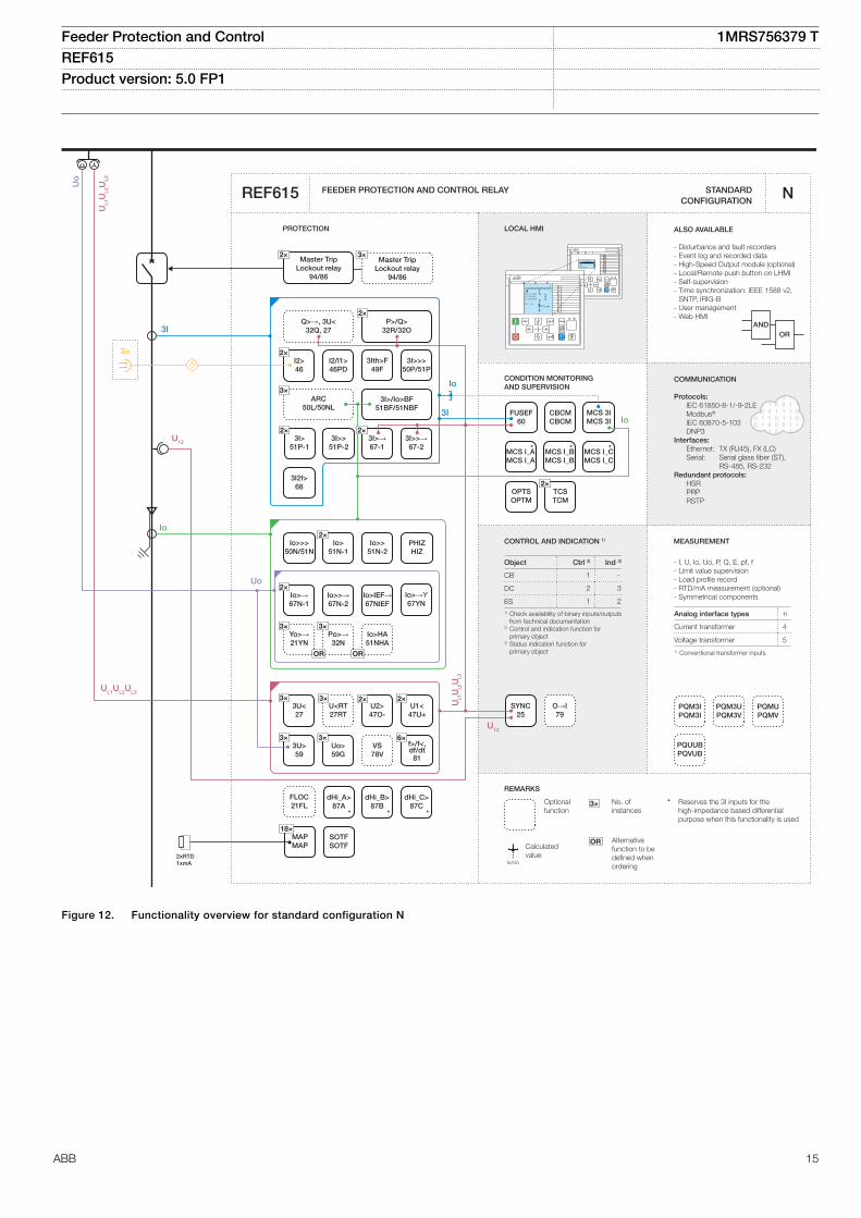
Figure 12. Functionality overview for standard configuration N
Feeder Protection and Control 1MRS756379 TREF615 Product version: 5.0 FP1
ABB 15
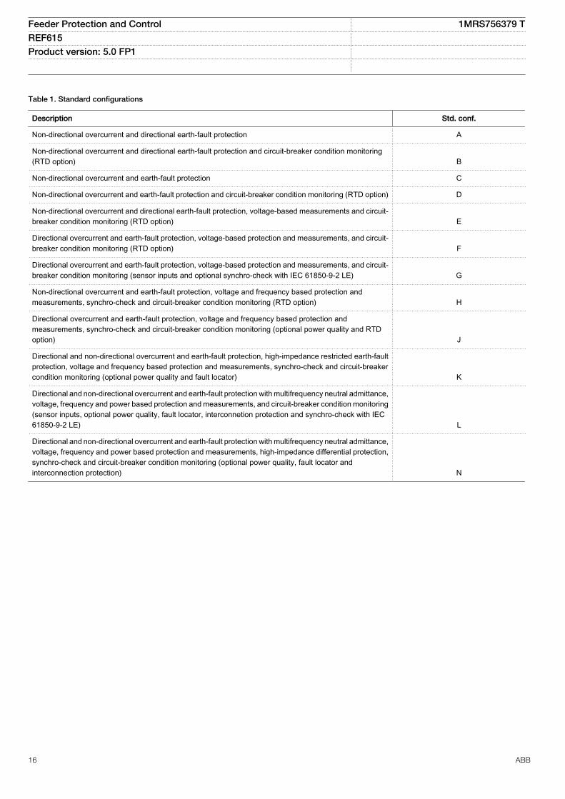
Table 1. Standard configurations
Description Std. conf.
Non-directional overcurrent and directional earth-fault protection A
Non-directional overcurrent and directional earth-fault protection and circuit-breaker condition monitoring(RTD option) B
Non-directional overcurrent and earth-fault protection C
Non-directional overcurrent and earth-fault protection and circuit-breaker condition monitoring (RTD option) D
Non-directional overcurrent and directional earth-fault protection, voltage-based measurements and circuit-breaker condition monitoring (RTD option) E
Directional overcurrent and earth-fault protection, voltage-based protection and measurements, and circuit-breaker condition monitoring (RTD option) F
Directional overcurrent and earth-fault protection, voltage-based protection and measurements, and circuit-breaker condition monitoring (sensor inputs and optional synchro-check with IEC 61850-9-2 LE) G
Non-directional overcurrent and earth-fault protection, voltage and frequency based protection andmeasurements, synchro-check and circuit-breaker condition monitoring (RTD option) H
Directional overcurrent and earth-fault protection, voltage and frequency based protection andmeasurements, synchro-check and circuit-breaker condition monitoring (optional power quality and RTDoption) J
Directional and non-directional overcurrent and earth-fault protection, high-impedance restricted earth-faultprotection, voltage and frequency based protection and measurements, synchro-check and circuit-breakercondition monitoring (optional power quality and fault locator) K
Directional and non-directional overcurrent and earth-fault protection with multifrequency neutral admittance,voltage, frequency and power based protection and measurements, and circuit-breaker condition monitoring(sensor inputs, optional power quality, fault locator, interconnetion protection and synchro-check with IEC61850-9-2 LE) L
Directional and non-directional overcurrent and earth-fault protection with multifrequency neutral admittance,voltage, frequency and power based protection and measurements, high-impedance differential protection,synchro-check and circuit-breaker condition monitoring (optional power quality, fault locator andinterconnection protection) N
Feeder Protection and Control 1MRS756379 TREF615 Product version: 5.0 FP1
16 ABB
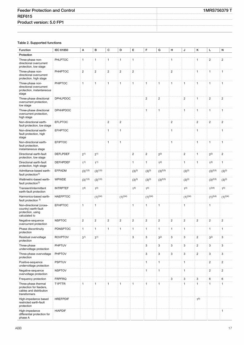
Table 2. Supported functions
Function IEC 61850 A B C D E F G H J K L N
ProtectionThree-phase non-directional overcurrentprotection, low stage
PHLPTOC 1 1 1 1 1 1 1 2 2
Three-phase non-directional overcurrentprotection, high stage
PHHPTOC 2 2 2 2 2 2 1 1 1
Three-phase non-directional overcurrentprotection, instantaneousstage
PHIPTOC 1 1 1 1 1 1 1 1 1 1 1 1
Three-phase directionalovercurrent protection,low stage
DPHLPDOC 2 2 2 1 2 2
Three-phase directionalovercurrent protection,high stage
DPHHPDOC 1 1 1 1 1 1
Non-directional earth-fault protection, low stage
EFLPTOC 2 2 2 2 2 2
Non-directional earth-fault protection, highstage
EFHPTOC 1 1 1 1 1
Non-directional earth-fault protection,instantaneous stage
EFIPTOC 1 1 1 1 1 1
Directional earth-faultprotection, low stage
DEFLPDEF 21) 21) 2 2 22) 2 1 22) 2
Directional earth-faultprotection, high stage
DEFHPDEF 11) 11) 1 1 12) 1 1 12) 1
Admittance-based earth-fault protection3)
EFPADM (3)1)3) (3)1)3) (3)3) (3)3) (3)2)3) (3)3) (3)2)3) (3)3)
Wattmetric-based earth-fault protection3)
WPWDE (3)1)3) (3)1)3) (3)3) (3)3) (3)2)3) (3)3) (3)2)3) (3)3)
Transient/intermittentearth-fault protection
INTRPTEF 14) 14) 14) 14) 14) 12)4) 14)
Harmonics-based earth-fault protection 3)
HAEFPTOC (1)3)4) (1)3)4) (1)3)4) (1)3)4) (1)3)4) (1)3)4)
Non-directional (cross-country) earth-faultprotection, usingcalculated Io
EFHPTOC 1 1 1 1 1 1 1
Negative-sequenceovercurrent protection
NSPTOC 2 2 2 2 2 2 2 2 2 2 2 2
Phase discontinuityprotection
PDNSPTOC 1 1 1 1 1 1 1 1 1 1 1
Residual overvoltageprotection
ROVPTOV 31) 31) 3 3 32) 3 3 2 32) 3
Three-phaseundervoltage protection
PHPTUV 3 3 3 3 2 3 3
Three-phase overvoltageprotection
PHPTOV 3 3 3 3 2 3 3
Positive-sequenceundervoltage protection
PSPTUV 1 1 1 2 2
Negative-sequenceovervoltage protection
NSPTOV 1 1 1 2 2
Frequency protection FRPFRQ 3 3 3 6 6Three-phase thermalprotection for feeders,cables and distributiontransformers
T1PTTR 1 1 1 1 1 1 1 1 1 1 1
High-impedance basedrestricted earth-faultprotection
HREFPDIF 15)
High-impedancedifferential protection forphase A
HIAPDIF 1
Feeder Protection and Control 1MRS756379 TREF615 Product version: 5.0 FP1
ABB 17
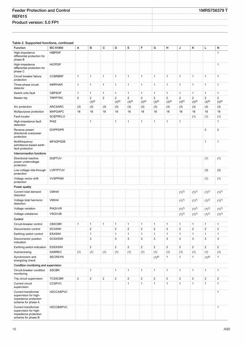
Table 2. Supported functions, continuedFunction IEC 61850 A B C D E F G H J K L N
High-impedancedifferential protection forphase B
HIBPDIF 1
High-impedancedifferential protection forphase C
HICPDIF 1
Circuit breaker failureprotection
CCBRBRF 1 1 1 1 1 1 1 1 1 1 1 1
Three-phase inrushdetector
INRPHAR 1 1 1 1 1 1 1 1 1 1 1 1
Switch onto fault CBPSOF 1 1 1 1 1 1 1 1 1 1 1 1Master trip TRPPTRC 2 2
(3)6)2 2
(3)6)2(3)6)
2(3)6)
2(3)6)
2(3)6)
2(3)6)
2(3)6)
2(3)6)
2(3)6)
Arc protection ARCSARC (3) (3) (3) (3) (3) (3) (3) (3) (3) (3) (3) (3)Multipurpose protection MAPGAPC 18 18 18 18 18 18 18 18 18 18 18 18Fault locator SCEFRFLO (1) (1) (1)High-impedance faultdetection
PHIZ 1 1 1 1 1 1 1 1
Reverse power/directional overpowerprotection
DOPPDPR 2 2
Multifrequencyadmittance-based earth-fault protection
MFADPSDE 1 1
Interconnection functionsDirectional reactivepower undervoltageprotection
DQPTUV (1) (1)
Low-voltage ride-throughprotection
LVRTPTUV (3) (3)
Voltage vector shiftprotection
VVSPPAM (1) (1)
Power qualityCurrent total demanddistortion
CMHAI (1)7) (1)7) (1)7) (1)7)
Voltage total harmonicdistortion
VMHAI (1)7) (1)7) (1)7) (1)7)
Voltage variation PHQVVR (1)7) (1)7) (1)7) (1)7)
Voltage unbalance VSQVUB (1)7) (1)7) (1)7) (1)7)
ControlCircuit-breaker control CBXCBR 1 1 1 1 1 1 1 1 1 1 1 1Disconnector control DCXSWI 2 2 2 2 2 2 2 2 2 2Earthing switch control ESXSWI 1 1 1 1 1 1 1 1 1 1Disconnector positionindication
DCSXSWI 3 3 3 3 3 3 3 3 3 3
Earthing switch indication ESSXSWI 2 2 2 2 2 2 2 2 2 2Autoreclosing DARREC (1) (1) (1) (1) (1) (1) (1) (1) (1) (1) (1) (1)Synchronism andenergizing check
SECRSYN (1)8) 1 1 1 (1)8) 1
Condition monitoring and supervisionCircuit-breaker conditionmonitoring
SSCBR 1 1 1 1 1 1 1 1 1 1
Trip circuit supervision TCSSCBR 2 2 2 2 2 2 2 2 2 2 2 2Current circuitsupervision
CCSPVC 1 1 1 1 1 1 1 1
Current transformersupervision for high-impedance protectionscheme for phase A
HZCCASPVC 1
Current transformersupervision for high-impedance protectionscheme for phase B
HZCCBSPVC 1
Feeder Protection and Control 1MRS756379 TREF615 Product version: 5.0 FP1
18 ABB
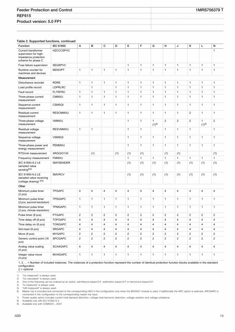
Table 2. Supported functions, continuedFunction IEC 61850 A B C D E F G H J K L N
Current transformersupervision for high-impedance protectionscheme for phase C
HZCCCSPVC 1
Fuse failure supervision SEQSPVC 1 1 1 1 1 1 1 1Runtime counter formachines and devices
MDSOPT 1 1 1 1 1 1 1 1 1 1 1 1
MeasurementDisturbance recorder RDRE 1 1 1 1 1 1 1 1 1 1 1 1Load profile record LDPRLRC 1 1 1 1 1 1 1 1 1 1Fault record FLTRFRC 1 1 1 1 1 1 1 1 1 1 1 1Three-phase currentmeasurement
CMMXU 1 1 1 1 1 1 1 1 1 1 1 1
Sequence currentmeasurement
CSMSQI 1 1 1 1 1 1 1 1 1 1 1 1
Residual currentmeasurement
RESCMMXU 1 1 1 1 1 1 1 1 1 2 1 1
Three-phase voltagemeasurement
VMMXU 1 1 1(1)8)
2 2 2 1(1)8)
2
Residual voltagemeasurement
RESVMMXU 1 1 1 1 1 1 1 1
Sequence voltagemeasurement
VSMSQI 1 1 1 1 1 1 1 1
Three-phase power andenergy measurement
PEMMXU 1 1 1 1 1 1 1 1
RTD/mA measurement XRGGIO130 (1) (1) (1) (1) (1) (1) (1)Frequency measurement FMMXU 1 1 1 1 1 1 1 1IEC 61850-9-2 LEsampled valuesending8)9)
SMVSENDER (1) (1) (1) (1) (1) (1) (1) (1)
IEC 61850-9-2 LEsampled value receiving(voltage sharing) 8)9)
SMVRCV (1) (1) (1) (1) (1) (1) (1) (1)
OtherMinimum pulse timer(2 pcs)
TPGAPC 4 4 4 4 4 4 4 4 4 4 4 4
Minimum pulse timer(2 pcs, second resolution)
TPSGAPC 1 1 1 1 1 1 1 1 1 1 1 1
Minimum pulse timer(2 pcs, minute resolution)
TPMGAPC 1 1 1 1 1 1 1 1 1 1 1 1
Pulse timer (8 pcs) PTGAPC 2 2 2 2 2 2 2 2 2 2 2 2Time delay off (8 pcs) TOFGAPC 4 4 4 4 4 4 4 4 4 4 4 4Time delay on (8 pcs) TONGAPC 4 4 4 4 4 4 4 4 4 4 4 4Set-reset (8 pcs) SRGAPC 4 4 4 4 4 4 4 4 4 4 4 4Move (8 pcs) MVGAPC 2 2 2 2 2 2 2 2 2 2 2 2Generic control point (16pcs)
SPCGAPC 2 2 2 2 2 2 2 2 2 2 2 2
Analog value scaling(4 pcs)
SCA4GAPC 4 4 4 4 4 4 4 4 4 4 4 4
Integer value move(4 pcs)
MVI4GAPC 1 1 1 1 1 1 1 1 1 1 1 1
1, 2, ... = Number of included instances. The instances of a protection function represent the number of identical protection function blocks available in the standardconfiguration.() = optional
1) "Uo measured" is always used.2) "Uo calculated" is always used.3) One of the following can be ordered as an option: admittance-based E/F, wattmetric-based E/F or harmonics-based E/F.4) "Io measured" is always used.5) "IoB measured" is always used.6) Master trip is included and connected to the corresponding HSO in the configuration only when the BIO0007 module is used. If additionally the ARC option is selected, ARCSARC is
connected in the configuration to the corresponding master trip input.7) Power quality option includes current total demand distortion, voltage total harmonic distortion, voltage variation and voltage unbalance.8) Available only with IEC 61850-9-29) Available only with COM0031...0037
Feeder Protection and Control 1MRS756379 TREF615 Product version: 5.0 FP1
ABB 19
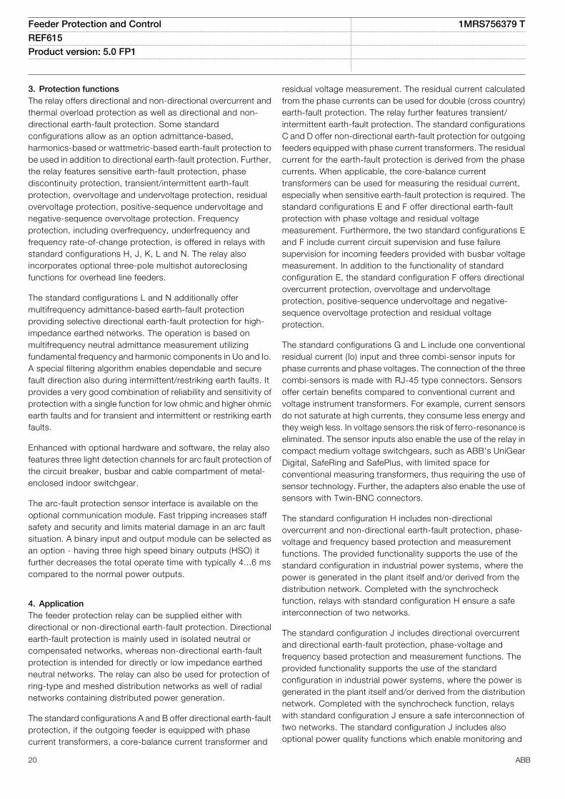
3. Protection functionsThe relay offers directional and non-directional overcurrent andthermal overload protection as well as directional and non-directional earth-fault protection. Some standardconfigurations allow as an option admittance-based,harmonics-based or wattmetric-based earth-fault protection tobe used in addition to directional earth-fault protection. Further,the relay features sensitive earth-fault protection, phasediscontinuity protection, transient/intermittent earth-faultprotection, overvoltage and undervoltage protection, residualovervoltage protection, positive-sequence undervoltage andnegative-sequence overvoltage protection. Frequencyprotection, including overfrequency, underfrequency andfrequency rate-of-change protection, is offered in relays withstandard configurations H, J, K, L and N. The relay alsoincorporates optional three-pole multishot autoreclosingfunctions for overhead line feeders.
The standard configurations L and N additionally offermultifrequency admittance-based earth-fault protectionproviding selective directional earth-fault protection for high-impedance earthed networks. The operation is based onmultifrequency neutral admittance measurement utilizingfundamental frequency and harmonic components in Uo and Io.A special filtering algorithm enables dependable and securefault direction also during intermittent/restriking earth faults. Itprovides a very good combination of reliability and sensitivity ofprotection with a single function for low ohmic and higher ohmicearth faults and for transient and intermittent or restriking earthfaults.
Enhanced with optional hardware and software, the relay alsofeatures three light detection channels for arc fault protection ofthe circuit breaker, busbar and cable compartment of metal-enclosed indoor switchgear.
The arc-fault protection sensor interface is available on theoptional communication module. Fast tripping increases staffsafety and security and limits material damage in an arc faultsituation. A binary input and output module can be selected asan option - having three high speed binary outputs (HSO) itfurther decreases the total operate time with typically 4...6 mscompared to the normal power outputs.
4. ApplicationThe feeder protection relay can be supplied either withdirectional or non-directional earth-fault protection. Directionalearth-fault protection is mainly used in isolated neutral orcompensated networks, whereas non-directional earth-faultprotection is intended for directly or low impedance earthedneutral networks. The relay can also be used for protection ofring-type and meshed distribution networks as well of radialnetworks containing distributed power generation.
The standard configurations A and B offer directional earth-faultprotection, if the outgoing feeder is equipped with phasecurrent transformers, a core-balance current transformer and
residual voltage measurement. The residual current calculatedfrom the phase currents can be used for double (cross country)earth-fault protection. The relay further features transient/intermittent earth-fault protection. The standard configurationsC and D offer non-directional earth-fault protection for outgoingfeeders equipped with phase current transformers. The residualcurrent for the earth-fault protection is derived from the phasecurrents. When applicable, the core-balance currenttransformers can be used for measuring the residual current,especially when sensitive earth-fault protection is required. Thestandard configurations E and F offer directional earth-faultprotection with phase voltage and residual voltagemeasurement. Furthermore, the two standard configurations Eand F include current circuit supervision and fuse failuresupervision for incoming feeders provided with busbar voltagemeasurement. In addition to the functionality of standardconfiguration E, the standard configuration F offers directionalovercurrent protection, overvoltage and undervoltageprotection, positive-sequence undervoltage and negative-sequence overvoltage protection and residual voltageprotection.
The standard configurations G and L include one conventionalresidual current (Io) input and three combi-sensor inputs forphase currents and phase voltages. The connection of the threecombi-sensors is made with RJ-45 type connectors. Sensorsoffer certain benefits compared to conventional current andvoltage instrument transformers. For example, current sensorsdo not saturate at high currents, they consume less energy andthey weigh less. In voltage sensors the risk of ferro-resonance iseliminated. The sensor inputs also enable the use of the relay incompact medium voltage switchgears, such as ABB’s UniGearDigital, SafeRing and SafePlus, with limited space forconventional measuring transformers, thus requiring the use ofsensor technology. Further, the adapters also enable the use ofsensors with Twin-BNC connectors.
The standard configuration H includes non-directionalovercurrent and non-directional earth-fault protection, phase-voltage and frequency based protection and measurementfunctions. The provided functionality supports the use of thestandard configuration in industrial power systems, where thepower is generated in the plant itself and/or derived from thedistribution network. Completed with the synchrocheckfunction, relays with standard configuration H ensure a safeinterconnection of two networks.
The standard configuration J includes directional overcurrentand directional earth-fault protection, phase-voltage andfrequency based protection and measurement functions. Theprovided functionality supports the use of the standardconfiguration in industrial power systems, where the power isgenerated in the plant itself and/or derived from the distributionnetwork. Completed with the synchrocheck function, relayswith standard configuration J ensure a safe interconnection oftwo networks. The standard configuration J includes alsooptional power quality functions which enable monitoring and
Feeder Protection and Control 1MRS756379 TREF615 Product version: 5.0 FP1
20 ABB
detecting current and voltage harmonics and short durationsystem disturbances.
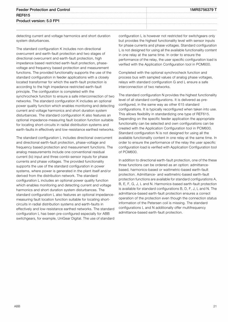
The standard configuration K includes non-directionalovercurrent and earth-fault protection and two stages ofdirectional overcurrent and earth-fault protection, highimpedance based restricted earth-fault protection, phase-voltage and frequency based protection and measurementfunctions. The provided functionality supports the use of thestandard configuration in feeder applications with a closelylocated transformer for which the earth-fault protection isaccording to the high impedance restricted earth-faultprinciple. The configuration is completed with thesynchrocheck function to ensure a safe interconnection of twonetworks. The standard configuration K includes an optionalpower quality function which enables monitoring and detectingcurrent and voltage harmonics and short duration systemdisturbances. The standard configuration K also features anoptional impedance-measuring fault location function suitablefor locating short-circuits in radial distribution systems andearth-faults in effectively and low-resistance earthed networks.
The standard configuration L includes directional overcurrentand directional earth-fault protection, phase-voltage andfrequency based protection and measurement functions. Theanalog measurements include one conventional residualcurrent (Io) input and three combi-sensor inputs for phasecurrents and phase voltages. The provided functionalitysupports the use of the standard configuration in powersystems, where power is generated in the plant itself and/orderived from the distribution network. The standardconfiguration L includes an optional power quality functionwhich enables monitoring and detecting current and voltageharmonics and short duration system disturbances. Thestandard configuration L also features an optional impedance-measuring fault location function suitable for locating short-circuits in radial distribution systems and earth-faults ineffectively and low-resistance earthed networks. The standardconfiguration L has been pre-configured especially for ABBswitchgears, for example, UniGear Digital. The use of standard
configuration L is however not restricted for switchgears onlybut provides the highest functionality level with sensor inputsfor phase currents and phase voltages. Standard configurationL is not designed for using all the available functionality contentin one relay at the same time. In order to ensure theperformance of the relay, the user specific configuration load isverified with the Application Configuration tool in PCM600.
Completed with the optional synchrocheck function andprocess bus with sampled values of analog phase voltages,relays with standard configuration G and L ensure a safeinterconnection of two networks.
The standard configuration N provides the highest functionalitylevel of all standard configurations. It is delivered as pre-configured, in the same way as other 615 standardconfigurations. It is typically reconfigured when taken into use.This allows flexibility in standardizing one type of REF615.Depending on the specific feeder application the appropriatefunctionality can be selected and own configurations can becreated with the Application Configuration tool in PCM600.Standard configuration N is not designed for using all theavailable functionality content in one relay at the same time. Inorder to ensure the performance of the relay the user specificconfiguration load is verified with Application Configuration toolof PCM600.
In addition to directional earth-fault protection, one of the thesethree functions can be ordered as an option: admittance-based, harmonics-based or wattmetric-based earth-faultprotection. Admittance- and wattmetric-based earth-faultprotection functions are available for standard configurations A,B, E, F, G, J, L and N. Harmonics-based earth-fault protectionis available for standard configurations B, D, F, J, L and N. Theadmittance-based earth-fault protection ensures a correctoperation of the protection even though the connection statusinformation of the Petersen coil is missing. The standardconfigurations L and N additionally offer multifrequencyadmittance-based earth-fault protection.
Feeder Protection and Control 1MRS756379 TREF615 Product version: 5.0 FP1
ABB 21
Io
3I
REF615Std. conf.
ANSI IEC
49F
50L/50NL
50P/51P
51BF/51NBF
51P-2/51P-1
67N 1)
67NIEF
3Ith>F
ARC
3I>>>
3I>/Io>BF
3I>>/3I>
Io→ 1)
Io>→IEF
B
1) or 51NHA (Io>HA), 21YN (Yo>→), 32N (Po>→)
3U Uo
Io
3I
REF615Std. conf.
ANSI IEC
47O-/59
47U+/27
50L/50NL
59G
81
U2>/3U>
U1</3U<
ARC
Uo>
f</f>, df/dt
H
REF615Std. conf.
ANSI IEC
49F
50L/50NL
50P/51P
51BF/51NBF
51P-2/51P-1
67N 1)
67NIEF
79
3Ith>F
ARC
3I>>>
3I>/Io>BF
3I>>/3I>
Io→ 1)
Io>→IEF
O→I
B
1) or 51NHA (Io>HA), 21YN (Yo>→), 32N (Po>→)
Io
3I
REF615Std. conf.
ANSI IEC
50L/50NL
50P/51P
51BF/51NBF
51N
51P-2/51P-1
ARC
3I>>>
3I>/Io>BF
Io>
3I>>/3I>
B
Cable Overhead line
GUID-D6509110-3E79-44CD-8DA9-D81FE934BDA4 V1 EN
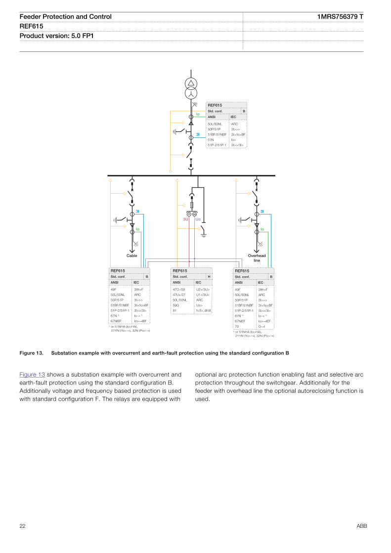
Figure 13. Substation example with overcurrent and earth-fault protection using the standard configuration B
Figure 13 shows a substation example with overcurrent andearth-fault protection using the standard configuration B.Additionally voltage and frequency based protection is usedwith standard configuration F. The relays are equipped with
optional arc protection function enabling fast and selective arcprotection throughout the switchgear. Additionally for thefeeder with overhead line the optional autoreclosing function isused.
Feeder Protection and Control 1MRS756379 TREF615 Product version: 5.0 FP1
22 ABB
Io
3I
REF615Std. conf.
ANSI IEC
49F
50L/50NL
50P/51P
51BF/51NBF
51P/51N
3Ith>F
ARC
3I>>>
3I>/Io>BF
3I/Io
D
Io
3I
REF615Std. conf.
ANSI IEC
21FL
49F
50L/50NL
50P/51P
51BF/51NBF
51P/51N
FLOC
3Ith>F
ARC
3I>>>
3I>/Io>BF
3I/Io
N
3I
Io
REF615Std. conf.
ANSI IEC
50L/50NL
50P/51P
51BF/51NBF
51N (SEF)
51P-2/51P-1
ARC
3I>>>
3I>/Io>BF
Io>
3I>>/3I>
D
Cable Cable
GUID-35166A11-E347-402F-A882-D04E1007577D V1 EN
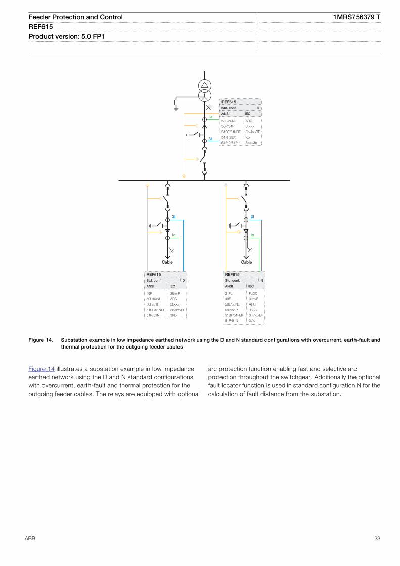
Figure 14. Substation example in low impedance earthed network using the D and N standard configurations with overcurrent, earth-fault andthermal protection for the outgoing feeder cables
Figure 14 illustrates a substation example in low impedanceearthed network using the D and N standard configurationswith overcurrent, earth-fault and thermal protection for theoutgoing feeder cables. The relays are equipped with optional
arc protection function enabling fast and selective arcprotection throughout the switchgear. Additionally the optionalfault locator function is used in standard configuration N for thecalculation of fault distance from the substation.
Feeder Protection and Control 1MRS756379 TREF615 Product version: 5.0 FP1
ABB 23
Io
3I
3U
Io
3I
3U
REF615Std. conf.
ANSI IEC
47O-/59
47U+/27
50L/50NL
50P/51P
51BF/51NBF
67/67N 1)
U2>/3U>
U1</3U<
ARC
3I>>>
3I>/Io>BF
3I→/Io→ 1)
L
Io
3I
3U
REF615Std. conf.
ANSI IEC
47O-/59
47U+/27
49F
50L/50NL
50P/51P
51BF/51NBF
67/67N
U2>/3U>
U1</3U<
3Ith>F
ARC
3I>>>
3I>/Io>BF
3I→/Io→
L
Io
3I
3U
REF615Std. conf.
ANSI IEC
47O-/59
47U+/27
49F
50L/50NL
50P/51P
51BF/51NBF
67/67N
79
U2>/3U>
U1</3U<
3Ith>F
ARC
3I>>>
3I>/Io>BF
3I→/Io→O→I
L
REF615Std. conf.
ANSI IEC
47O-/59
47U+/27
50L/50NL
50P/51P
51BF/51NBF
67
U2>/3U>
U1</3U<
ARC
3I>>>
3I>/Io>BF
3I→
G
Io
3I
3U
REF615Std. conf.
ANSI IEC
47O-/59
47U+/27
49F
50L/50NL
50P/51P
51BF/51NBF
67/67N
U2>/3U>
U1</3U<
3Ith>F
ARC
3I>>>
3I>/Io>BF
3I→/Io→
L
Io
3I
3U
REF615Std. conf.
ANSI IEC
47O-/59
47U+/27
49F
50L/50NL
50P/51P
51BF/51NBF
67/67N
79
U2>/3U>
U1</3U<
3Ith>F
ARC
3I>>>
3I>/Io>BF
3I→/Io→O→I
L
REF615Std. conf.
ANSI IEC
47O-/59
47U+/27
50L/50NL
50P/51P
51BF/51NBF
67/67N 1)
U2>/3U>
U1</3U<
ARC
3I>>>
3I>/Io>BF
3I→/Io→ 1)
L
3I
3U
1) used in non-directional mode 1) used in non-directional mode
CableOverhead line
Overhead line
Cable
GUID-52115F97-519B-40F3-B676-1CC27990CA50 V1 EN
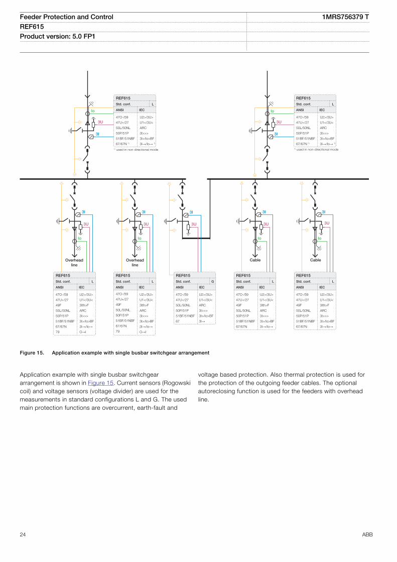
Figure 15. Application example with single busbar switchgear arrangement
Application example with single busbar switchgeararrangement is shown in Figure 15. Current sensors (Rogowskicoil) and voltage sensors (voltage divider) are used for themeasurements in standard configurations L and G. The usedmain protection functions are overcurrent, earth-fault and
voltage based protection. Also thermal protection is used forthe protection of the outgoing feeder cables. The optionalautoreclosing function is used for the feeders with overheadline.
Feeder Protection and Control 1MRS756379 TREF615 Product version: 5.0 FP1
24 ABB
3U Uo
Io
3I
REF615Std. conf.
ANSI IEC
25
47O-/59
47U+/27
50L/50NL
50P/51P
51BF/51NBF
67/67N
SYNC
U2>/3U>
U1</3U<
ARC
3I>>>
3I>/Io>BF
3I→/Io→
N
3UUo
Io
3I
REF615Std. conf.
ANSI IEC
25
47O-/59
47U+/27
50L/50NL
50P/51P
51BF/51NBF
67/67N
SYNC
U2>/3U>
U1</3U<
ARC
3I>>>
3I>/Io>BF
3I→/Io→
N
3UUo
3I 3I
3I
3U Uo
REF615Std. conf.
ANSI IEC
47O-/59
47U+/27
50L/50NL
59G
81
U2>/3U>
U1</3U<
ARC
Uo>
f</f>, df/dt
H
REF615Std. conf.
ANSI IEC
27/59
49F
50L/50NL
50P/51P
51BF/51NBF
51P/51N
81
87NH
3U</3U>
3Ith>F
ARC
3I>>>
3I>/Io>BF
3I/Io
f<, f>, df/dt
dIoHi>
K
REF615Std. conf.
ANSI IEC
27/59
49F
50L/50NL
50P/51P
51BF/51NBF
51P/51N
81
87NH
3U</3U>
3Ith>F
ARC
3I>>>
3I>/Io>BF
3I/Io
f<, f>, df/dt
dIoHi>
K
REF615Std. conf.
ANSI IEC
25
47O-/59
47U+/27
50L/50NL
50P/51P
51BF/51NBF
59G
67
81
SYNC
U2>/3U>
U1</3U<
ARC
3I>>>
3I>/Io>BF
Uo>
3I→f</f>, df/dt
N
Io
3I
Iob
REF615Std. conf.
ANSI IEC
27/59
49F
50L/50NL
50P/51P
51BF/51NBF
51P/51N
81
87NH
3U</3U>
3Ith>F
ARC
3I>>>
3I>/Io>BF
3I/Io
f<, f>, df/dt
dIoHi>
K
Io Io
IobIob
GUID-51FCF15D-3965-4719-AEF5-F37617767572 V1 EN
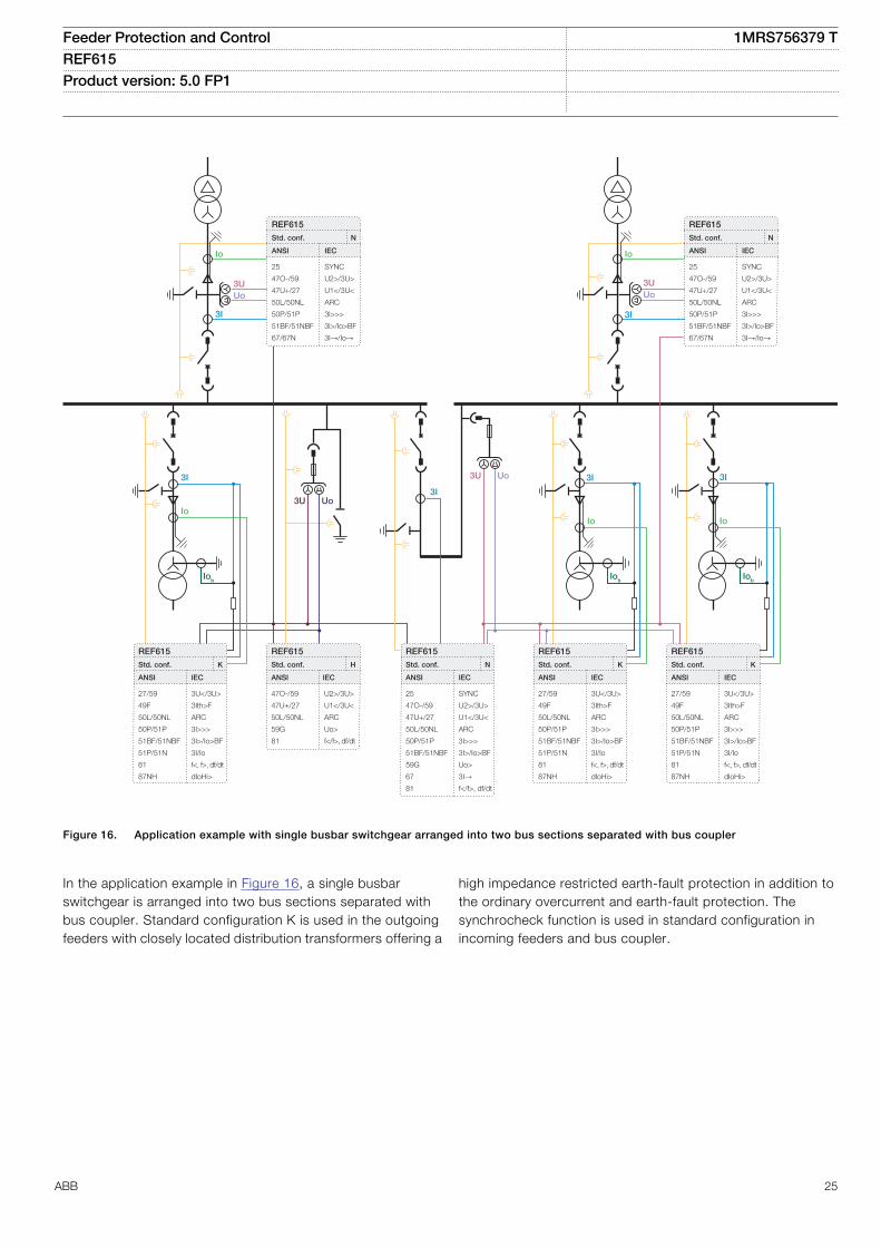
Figure 16. Application example with single busbar switchgear arranged into two bus sections separated with bus coupler
In the application example in Figure 16, a single busbarswitchgear is arranged into two bus sections separated withbus coupler. Standard configuration K is used in the outgoingfeeders with closely located distribution transformers offering a
high impedance restricted earth-fault protection in addition tothe ordinary overcurrent and earth-fault protection. Thesynchrocheck function is used in standard configuration inincoming feeders and bus coupler.
Feeder Protection and Control 1MRS756379 TREF615 Product version: 5.0 FP1
ABB 25
Io
3I
REF615Std. conf.
ANSI IEC
25
47O-/59
47U+/27
50L/50NL
50P/51P
51BF/51NBF
59G
67
SYNC
U2>/3U>
U1</3U<
ARC
3I>>>
3I>/Io>BF
Uo>
3I→
N
3UUo
Io
3I
REF615Std. conf.
ANSI IEC
25
47O-/59
47U+/27
50L/50NL
50P/51P
51BF/51NBF
59G
67
SYNC
U2>/3U>
U1</3U<
ARC
3I>>>
3I>/Io>BF
Uo>
3I→
N
3UUo
REF615Std. conf.
ANSI IEC
47O-/59
47U+/27
50L/50NL
59G
81
U2>/3U>
U1</3U<
ARC
Uo>
f</f>, df/dt
N
3U Uo3I
REF615Std. conf.
ANSI IEC
25
47O-/59
47U+/27
50L/50NL
50P/51P
51BF/51NBF
59G
67
81
SYNC
U2>/3U>
U1</3U<
ARC
3I>>>
3I>/Io>BF
Uo>
3I→f</f>, df/dt
N
Io
3I
REF615Std. conf.
ANSI IEC
49F
50L/50NL
50P/51P
51BF/51NBF
51P/51N
67NIEF
3Ith>F
ARC
3I>>>
3I>/Io>BF
3I/Io
Io>IEF→
N
Io
3I
REF615Std. conf.
ANSI IEC
47O-/59
47U+/27
49F
50L/50NL
50P/51P
51BF/51NBF
67/67N
79
U2>/3U>
U1</3U<
3Ith>F
ARC
3I>>>
3I>/Io>BF
3I→/Io→O→I
N
3U Uo
Io
3I
REF615Std. conf.
ANSI IEC
49F
50L/50NL
50P/51P
51BF/51NBF
51P/51N
67NIEF
3Ith>F
ARC
3I>>>
3I>/Io>BF
3I/Io
Io>IEF→
N
Cable Overhead line
Cable
GUID-D9276030-D56F-4396-A5F1-A81CDBCEE500 V1 EN
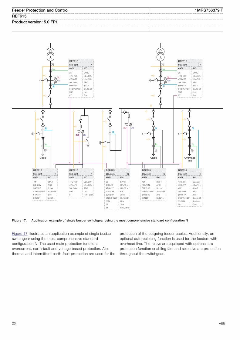
Figure 17. Application example of single busbar switchgear using the most comprehensive standard configuration N
Figure 17 illustrates an application example of single busbarswitchgear using the most comprehensive standardconfiguration N. The used main protection functionsovercurrent, earth-fault and voltage based protection. Alsothermal and intermittent earth-fault protection are used for the
protection of the outgoing feeder cables. Additionally, anoptional autoreclosing function is used for the feeders withoverhead line. The relays are equipped with optional arcprotection function enabling fast and selective arc protectionthroughout the switchgear.
Feeder Protection and Control 1MRS756379 TREF615 Product version: 5.0 FP1
26 ABB
REF615Std. conf.
ANSI IEC
25
47O-/59
47U+/27
49F
50L/50NL
59G
60
67/67N
81
SYNC
U2>/3U<
U1</3U>
3Ith>F
ARC
Uo>
FUSEF
3I→/Io→f</f>,df/dt
J
U12
3U Uo
Io
3I
GUID-5F636A0B-E6FC-4227-900B-1E2BAC9A1AB9 V1 EN
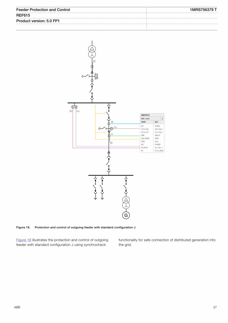
Figure 18. Protection and control of outgoing feeder with standard configuration J
Figure 18 illustrates the protection and control of outgoingfeeder with standard configuration J using synchrocheck
functionality for safe connection of distributed generation intothe grid.
Feeder Protection and Control 1MRS756379 TREF615 Product version: 5.0 FP1
ABB 27
Zone A Zone B
3I3I
Incoming/OutgoingFeeder for Zone A
Incoming/OutgoingFeeder for Zone B
3I3I
Bus coupler
3I 3I
REF615
Std. conf.
ANSI IEC
47O-/59
47U+/27
51BF
59G
81
87A
87B
87C
MCS I_A
MCS I_B
MCS I_C
U2>/3U>
U1</3U<
3I>
Uo>
f>/f<,df/dt
dHi_A>
dHi_B>
dHi_C>
MCS I_A
MCS I_B
MCS I_C
N
REF615
Std. conf.
ANSI IEC
47O-/59
47U+/27
51BF
59G
81
87A
87B
87C
MCS I_A
MCS I_B
MCS I_C
U2>/3U>
U1</3U<
3I>
Uo>
f>/f<,df/dt
dHi_A>
dHi_B>
dHi_C>
MCS I_A
MCS I_B
MCS I_C
N
3U Uo 3U Uo
GUID-9D66E4ED-7461-4822-9C76-DBA2878DDDF1 V1 EN
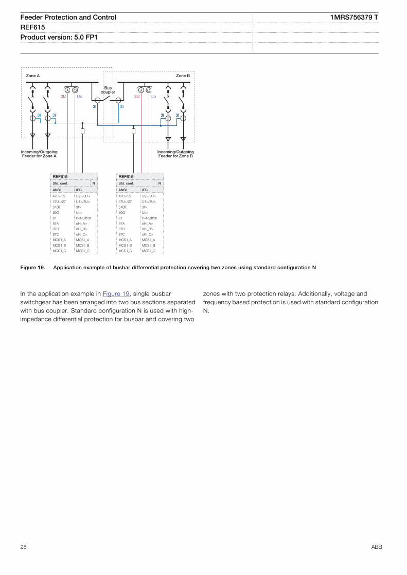
Figure 19. Application example of busbar differential protection covering two zones using standard configuration N
In the application example in Figure 19, single busbarswitchgear has been arranged into two bus sections separatedwith bus coupler. Standard configuration N is used with high-impedance differential protection for busbar and covering two
zones with two protection relays. Additionally, voltage andfrequency based protection is used with standard configurationN.
Feeder Protection and Control 1MRS756379 TREF615 Product version: 5.0 FP1
28 ABB
5. Supported ABB solutionsThe 615 series protection relays together with the SubstationManagement Unit COM600S constitute a genuine IEC 61850solution for reliable power distribution in utility and industrialpower systems. To facilitate the system engineering, ABB'srelays are supplied with connectivity packages. Theconnectivity packages include a compilation of software andrelay-specific information, including single-line diagramtemplates and a full relay data model. The data model includesevent and parameter lists. With the connectivity packages, therelays can be readily configured using PCM600 and integratedwith COM600S or the network control and managementsystem MicroSCADA Pro.
The 615 series relays offer native support for IEC 61850 Edition2 also including binary and analog horizontal GOOSEmessaging. In addition, process bus with the sending ofsampled values of analog currents and voltages and thereceiving of sampled values of voltages is supported.Compared to traditional hard-wired, inter-device signaling,peer-to-peer communication over a switched Ethernet LANoffers an advanced and versatile platform for power systemprotection. Among the distinctive features of the protectionsystem approach, enabled by the full implementation of the IEC61850 substation automation standard, are fastcommunication capability, continuous supervision of theprotection and communication system's integrity, and aninherent flexibility regarding reconfiguration and upgrades.Thisprotection relay series is able to optimally utilize interoperabilityprovided by the IEC 61850 Edition 2 features.
At substation level, COM600S uses the data content of the bay-level devices to enhance substation level functionality.
COM600S features a Web browser-based HMI, which providesa customizable graphical display for visualizing single-linemimic diagrams for switchgear bay solutions. The SLD featureis especially useful when 615 series relays without the optionalsingle-line diagram feature are used. The Web HMI ofCOM600S also provides an overview of the whole substation,including relay-specific single-line diagrams, which makesinformation easily accessible. Substation devices andprocesses can also be remotely accessed through the WebHMI, which improves personnel safety.
In addition, COM600S can be used as a local data warehousefor the substation's technical documentation and for thenetwork data collected by the devices. The collected networkdata facilitates extensive reporting and analyzing of networkfault situations by using the data historian and event handlingfeatures of COM600S. The historical data can be used foraccurate monitoring of process and equipment performance,using calculations based on both real-time and historicalvalues. A better understanding of the process dynamics isachieved by combining time-based process measurementswith production and maintenance events.
COM600S can also function as a gateway and provideseamless connectivity between the substation devices andnetwork-level control and management systems, such asMicroSCADA Pro and System 800xA.
GOOSE Analyzer interface in COM600S enables the followingand analyzing the horizontal IEC 61850 application duringcommissioning and operation at station level. It logs all GOOSEevents during substation operation to enable improved systemsupervision.
Table 3. Supported ABB solutions
Product Version
Substation Management Unit COM600S 4.0 SP1 or later
4.1 or later (Edition 2)
MicroSCADA Pro SYS 600 9.3 FP2 or later
9.4 or later (Edition 2)
System 800xA 5.1 or later
Feeder Protection and Control 1MRS756379 TREF615 Product version: 5.0 FP1
ABB 29
PCM600Ethernet switch
Utility: IEC 60870-5-104Industry: OPC
COM600SWeb HMI
ABBMicroSCADA Pro/
System 800xA
Analog and binary horizontal GOOSE communication IEC 61850
PCM600Ethernet switch
COM600SWeb HMI
Analog and binary horizontal GOOSE communication IEC 61850
GUID-4D002AA0-E35D-4D3F-A157-01F1A3044DDB V4 EN
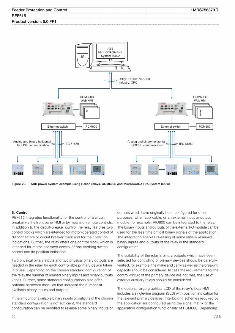
Figure 20. ABB power system example using Relion relays, COM600S and MicroSCADA Pro/System 800xA
6. ControlREF615 integrates functionality for the control of a circuitbreaker via the front panel HMI or by means of remote controls.In addition to the circuit-breaker control the relay features twocontrol blocks which are intended for motor-operated control ofdisconnectors or circuit breaker truck and for their positionindications. Further, the relay offers one control block which isintended for motor-operated control of one earthing switchcontrol and its position indication.
Two physical binary inputs and two physical binary outputs areneeded in the relay for each controllable primary device takeninto use. Depending on the chosen standard configuration ofthe relay the number of unused binary inputs and binary outputsvaries. Further, some standard configurations also offeroptional hardware modules that increase the number ofavailable binary inputs and outputs.
If the amount of available binary inputs or outputs of the chosenstandard configuration is not sufficient, the standardconfiguration can be modified to release some binary inputs or
outputs which have originally been configured for otherpurposes, when applicable, or an external input or outputmodule, for example, RIO600 can be integrated to the relay.The binary inputs and outputs of the external I/O module can beused for the less time critical binary signals of the application.The integration enables releasing of some initially reservedbinary inputs and outputs of the relay in the standardconfiguration.
The suitability of the relay's binary outputs which have beenselected for controlling of primary devices should be carefullyverified, for example, the make and carry as well as the breakingcapacity should be considered. In case the requirements for thecontrol-circuit of the primary device are not met, the use ofexternal auxiliary relays should be considered.
The optional large graphical LCD of the relay's local HMIincludes a single-line diagram (SLD) with position indication forthe relevant primary devices. Interlocking schemes required bythe application are configured using the signal matrix or theapplication configuration functionality of PCM600. Depending
Feeder Protection and Control 1MRS756379 TREF615 Product version: 5.0 FP1
30 ABB
on the standard configuration, the relay also incorporates asynchrocheck function to ensure that the voltage, phase angleand frequency on either side of an open circuit breaker satisfythe conditions for safe interconnection of two networks.
7. MeasurementsThe relay continuously measures the phase currents, thesymmetrical components of the currents and the residualcurrent. If the relay includes voltage measurements, it alsomeasures the residual voltage, the phase voltages and thevoltage sequence components. Depending on the standardconfiguration the relay additionally offers frequencymeasurement. The relay also calculates the demand value ofthe current over a user-selectable, pre-set time frame, thethermal overload of the protected object, and the phaseunbalance based on the ratio between the negative-sequenceand positive-sequence current.
Furthermore, the relay offers three-phase power and energymeasurement including power factor.
The measured values can be accessed via the local HMI orremotely via the communication interface of the relay. Thevalues can also be accessed locally or remotely using the WebHMI.
The relay is provided with a load profile recorder. The loadprofile feature stores the historical load data captured at aperiodical time interval (demand interval). The records are inCOMTRADE format.
8. Power qualityIn the EN standards, power quality is defined through thecharacteristics of the supply voltage. Transients, short-durationand long-duration voltage variations and unbalance andwaveform distortions are the key characteristics describingpower quality. The distortion monitoring functions are used formonitoring the current total demand distortion and the voltagetotal harmonic distortion.
Power quality monitoring is an essential service that utilities canprovide for their industrial and key customers. A monitoringsystem can provide information about system disturbances andtheir possible causes. It can also detect problem conditionsthroughout the system before they cause customer complaints,equipment malfunctions and even equipment damage orfailure. Power quality problems are not limited to the utility sideof the system. In fact, the majority of power quality problemsare localized within customer facilities. Thus, power qualitymonitoring is not only an effective customer service strategy butalso a way to protect a utility's reputation for quality power andservice.
The protection relay has the following power quality monitoringfunctions.
• Voltage variation• Voltage unbalance• Current harmonics• Voltage harmonics
The voltage unbalance and voltage variation functions are usedfor measuring short-duration voltage variations and monitoringvoltage unbalance conditions in power transmission anddistribution networks.
The voltage and current harmonics functions provide a methodfor monitoring the power quality by means of the currentwaveform distortion and voltage waveform distortion. Thefunctions provides a short-term three-second average and along-term demand for total demand distortion TDD and totalharmonic distortion THD.
9. Fault locationThe relay features an optional impedance-measuring faultlocation function suitable for locating short-circuits in radialdistribution systems. Earth faults can be located in effectivelyand low-resistance earthed networks. Under circumstanceswhere the fault current magnitude is at least of the same orderof magnitude or higher than the load current, earth faults canalso be located in isolated neutral distribution networks. Thefault location function identifies the type of the fault and thencalculates the distance to the fault point. An estimate of thefault resistance value is also calculated. The estimate providesinformation about the possible fault cause and the accuracy ofthe estimated distance to the fault point.
10. Disturbance recorderThe relay is provided with a disturbance recorder featuring up to12 analog and 64 binary signal channels.The analog channelscan be set to record either the waveform or the trend of thecurrents and voltages measured.
The analog channels can be set to trigger the recording functionwhen the measured value falls below or exceeds the set values.The binary signal channels can be set to start a recording eitheron the rising or the falling edge of the binary signal or on both.
By default, the binary channels are set to record external orinternal relay signals, for example, the start or trip signals of therelay stages, or external blocking or control signals. Binary relaysignals, such as protection start and trip signals, or an externalrelay control signal via a binary input, can be set to trigger therecording. Recorded information is stored in a nonvolatilememory and can be uploaded for subsequent fault analysis.
11. Event logTo collect sequence-of-events information, the relay has a non-volatile memory capable of storing 1024 events with theassociated time stamps. The non-volatile memory retains itsdata even if the relay temporarily loses its auxiliary supply. Theevent log facilitates detailed pre- and post-fault analyses of
Feeder Protection and Control 1MRS756379 TREF615 Product version: 5.0 FP1
ABB 31
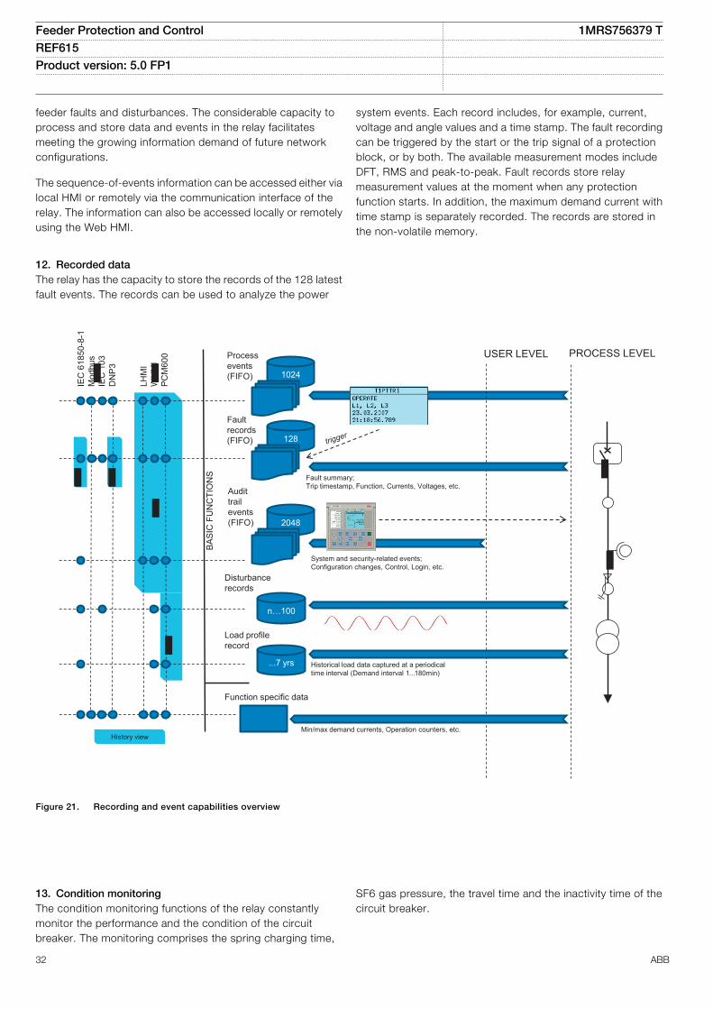
feeder faults and disturbances. The considerable capacity toprocess and store data and events in the relay facilitatesmeeting the growing information demand of future networkconfigurations.
The sequence-of-events information can be accessed either vialocal HMI or remotely via the communication interface of therelay. The information can also be accessed locally or remotelyusing the Web HMI.
12. Recorded dataThe relay has the capacity to store the records of the 128 latestfault events. The records can be used to analyze the power
system events. Each record includes, for example, current,voltage and angle values and a time stamp. The fault recordingcan be triggered by the start or the trip signal of a protectionblock, or by both. The available measurement modes includeDFT, RMS and peak-to-peak. Fault records store relaymeasurement values at the moment when any protectionfunction starts. In addition, the maximum demand current withtime stamp is separately recorded. The records are stored inthe non-volatile memory.
1024
PROCESS LEVELUSER LEVEL
Fault summary; Trip timestamp, Function, Currents, Voltages, etc.
BASI
C F
UN
CTI
ON
S
IEC
618
50-8
-1M
odbu
sIE
C 1
03D
NP3
LHM
IW
HM
IPC
M60
0 Process events (FIFO)
128
Fault records (FIFO)
System and security-related events;Configuration changes, Control, Login, etc.
2048
Audittrailevents(FIFO)
n…100
Disturbance records
...7 yrs
Load profile record
Historical load data captured at a periodical time interval (Demand interval 1 ...180min)
Function specific data
Min/max demand currents, Operation counters, etc. History view
GUID-CDF1DC16-AF90-406F-B21B-EF6C7F60BCCA V1 EN
Figure 21. Recording and event capabilities overview
13. Condition monitoringThe condition monitoring functions of the relay constantlymonitor the performance and the condition of the circuitbreaker. The monitoring comprises the spring charging time,
SF6 gas pressure, the travel time and the inactivity time of thecircuit breaker.
Feeder Protection and Control 1MRS756379 TREF615 Product version: 5.0 FP1
32 ABB
The monitoring functions provide operational circuit breakerhistory data, which can be used for scheduling preventivecircuit breaker maintenance.
In addition, the relay includes a runtime counter for monitoringof how many hours a protected device has been in operationthus enabling scheduling of time-based preventivemaintenance of the device.
14. Trip-circuit supervisionThe trip-circuit supervision continuously monitors theavailability and operability of the trip circuit. It provides open-circuit monitoring both when the circuit breaker is in its closedand in its open position. It also detects loss of circuit-breakercontrol voltage.
15. Self-supervisionThe relay’s built-in self-supervision system continuouslymonitors the state of the relay hardware and the operation ofthe relay software. Any fault or malfunction detected is used foralerting the operator.
A permanent relay fault blocks the protection functions toprevent incorrect operation.
16. Fuse failure supervisionDepending on the chosen standard configuration, the relayincludes fuse failure supervision functionality. The fuse failuresupervision detects failures between the voltage measurementcircuit and the relay. The failures are detected either by thenegative sequence-based algorithm or by the delta voltage anddelta current algorithm. Upon the detection of a failure, the fusefailure supervision function activates an alarm and blocksvoltage-dependent protection functions from unintendedoperation.
17. Current circuit supervisionDepending on the chosen standard configuration, the relayincludes current circuit supervision. Current circuit supervisionis used for detecting faults in the current transformer secondarycircuits. On detecting of a fault the current circuit supervisionfunction activates an alarm LED and blocks certain protectionfunctions to avoid unintended operation. The current circuitsupervision function calculates the sum of the phase currentsfrom the protection cores and compares the sum with themeasured single reference current from a core balance currenttransformer or from separate cores in the phase currenttransformers.
18. Access controlTo protect the relay from unauthorized access and to maintaininformation integrity, the relay is provided with a four-level, role-based authentication system with administrator-programmableindividual passwords for the viewer, operator, engineer andadministrator levels. The access control applies to the localHMI, the Web HMI and PCM600.
19. Inputs and outputsDepending on the standard configuration selected, the relay isequipped with three phase-current inputs and one residual-current input for non-directional earth-fault protection, or threephase-current inputs, one residual-current input and oneresidual voltage input for directional earth-fault protection orthree phase-current inputs, one residual-current input, threephase-voltage inputs and one residual voltage input fordirectional earth-fault protection and directional overcurrentprotection. Standard configurations G and L include oneconventional residual current (Io 0.2/1 A) input and three sensorinputs for the direct connection of three combi-sensors withRJ-45 connectors. As an alternative to combi-sensors,separate current and voltage sensors can be utilized usingadapters. Furthermore, the adapters also enable the use ofsensors with Twin-BNC connectors.
The phase-current inputs are rated 1/5 A. Two optionalresidual-current inputs are available, that is, 1/5 A or 0.2/1 A.The 0.2/1 A input is normally used in applications requiringsensitive earth-fault protection and featuring core-balancecurrent transformers. The three phase-voltage inputs and theresidual-voltage input covers the rated voltages 60...210 V.Both phase-to-phase voltages and phase-to-earth voltagescan be connected.
The phase-current input 1 A or 5 A, the residual-current input 1A or 5 A, alternatively 0.2 A or 1 A, and the rated voltage of theresidual voltage input are selected in the relay software. Inaddition, the binary input thresholds 16…176 V DC are selectedby adjusting the relay’s parameter settings.
All binary input and output contacts are freely configurable withthe signal matrix or application configuration functionality ofPCM600.
See the Input/output overview table and the terminal diagramsfor more information about the inputs and outputs.
Optionally, a binary input and output module can be selected. Ithas three high speed binary outputs (HSO) and it decreases thetotal operate time with typically 4...6 ms compared to thenormal power outputs.
Feeder Protection and Control 1MRS756379 TREF615 Product version: 5.0 FP1
ABB 33
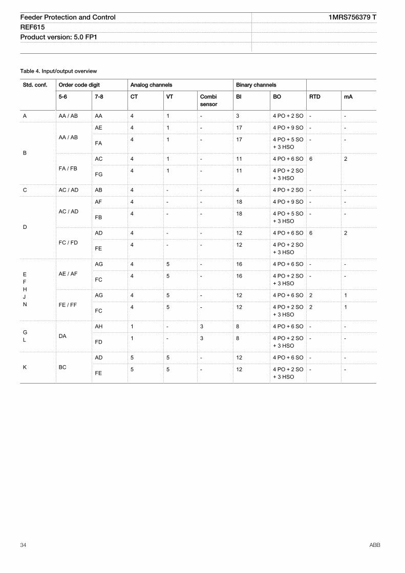
Table 4. Input/output overview
Std. conf. Order code digit Analog channels Binary channels
5-6 7-8 CT VT Combisensor
BI BO RTD mA
A AA / AB AA 4 1 - 3 4 PO + 2 SO - -
B
AA / AB
AE 4 1 - 17 4 PO + 9 SO - -
FA 4 1 - 17 4 PO + 5 SO+ 3 HSO
- -
FA / FB
AC 4 1 - 11 4 PO + 6 SO 6 2
FG 4 1 - 11 4 PO + 2 SO+ 3 HSO
C AC / AD AB 4 - - 4 4 PO + 2 SO - -
D
AC / AD
AF 4 - - 18 4 PO + 9 SO - -
FB 4 - - 18 4 PO + 5 SO+ 3 HSO
- -
FC / FD
AD 4 - - 12 4 PO + 6 SO 6 2
FE 4 - - 12 4 PO + 2 SO+ 3 HSO
EFHJN
AE / AF
AG 4 5 - 16 4 PO + 6 SO - -
FC 4 5 - 16 4 PO + 2 SO+ 3 HSO
- -
FE / FF
AG 4 5 - 12 4 PO + 6 SO 2 1
FC 4 5 - 12 4 PO + 2 SO+ 3 HSO
2 1
GL DA
AH 1 - 3 8 4 PO + 6 SO - -
FD 1 - 3 8 4 PO + 2 SO+ 3 HSO
- -
K BC
AD 5 5 - 12 4 PO + 6 SO - -
FE 5 5 - 12 4 PO + 2 SO+ 3 HSO
- -
Feeder Protection and Control 1MRS756379 TREF615 Product version: 5.0 FP1
34 ABB
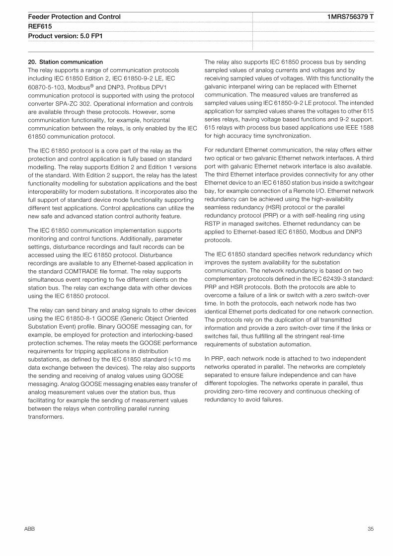
20. Station communicationThe relay supports a range of communication protocolsincluding IEC 61850 Edition 2, IEC 61850-9-2 LE, IEC
60870-5-103, Modbus® and DNP3. Profibus DPV1communication protocol is supported with using the protocolconverter SPA-ZC 302. Operational information and controlsare available through these protocols. However, somecommunication functionality, for example, horizontalcommunication between the relays, is only enabled by the IEC61850 communication protocol.
The IEC 61850 protocol is a core part of the relay as theprotection and control application is fully based on standardmodelling. The relay supports Edition 2 and Edition 1 versionsof the standard. With Edition 2 support, the relay has the latestfunctionality modelling for substation applications and the bestinteroperability for modern substations. It incorporates also thefull support of standard device mode functionality supportingdifferent test applications. Control applications can utilize thenew safe and advanced station control authority feature.
The IEC 61850 communication implementation supportsmonitoring and control functions. Additionally, parametersettings, disturbance recordings and fault records can beaccessed using the IEC 61850 protocol. Disturbancerecordings are available to any Ethernet-based application inthe standard COMTRADE file format. The relay supportssimultaneous event reporting to five different clients on thestation bus. The relay can exchange data with other devicesusing the IEC 61850 protocol.
The relay can send binary and analog signals to other devicesusing the IEC 61850-8-1 GOOSE (Generic Object OrientedSubstation Event) profile. Binary GOOSE messaging can, forexample, be employed for protection and interlocking-basedprotection schemes. The relay meets the GOOSE performancerequirements for tripping applications in distributionsubstations, as defined by the IEC 61850 standard (<10 msdata exchange between the devices). The relay also supportsthe sending and receiving of analog values using GOOSEmessaging. Analog GOOSE messaging enables easy transfer ofanalog measurement values over the station bus, thusfacilitating for example the sending of measurement valuesbetween the relays when controlling parallel runningtransformers.
The relay also supports IEC 61850 process bus by sendingsampled values of analog currents and voltages and byreceiving sampled values of voltages. With this functionality thegalvanic interpanel wiring can be replaced with Ethernetcommunication. The measured values are transferred assampled values using IEC 61850-9-2 LE protocol. The intendedapplication for sampled values shares the voltages to other 615series relays, having voltage based functions and 9-2 support.615 relays with process bus based applications use IEEE 1588for high accuracy time synchronization.
For redundant Ethernet communication, the relay offers eithertwo optical or two galvanic Ethernet network interfaces. A thirdport with galvanic Ethernet network interface is also available.The third Ethernet interface provides connectivity for any otherEthernet device to an IEC 61850 station bus inside a switchgearbay, for example connection of a Remote I/O. Ethernet networkredundancy can be achieved using the high-availabilityseamless redundancy (HSR) protocol or the parallelredundancy protocol (PRP) or a with self-healing ring usingRSTP in managed switches. Ethernet redundancy can beapplied to Ethernet-based IEC 61850, Modbus and DNP3protocols.
The IEC 61850 standard specifies network redundancy whichimproves the system availability for the substationcommunication. The network redundancy is based on twocomplementary protocols defined in the IEC 62439-3 standard:PRP and HSR protocols. Both the protocols are able toovercome a failure of a link or switch with a zero switch-overtime. In both the protocols, each network node has twoidentical Ethernet ports dedicated for one network connection.The protocols rely on the duplication of all transmittedinformation and provide a zero switch-over time if the links orswitches fail, thus fulfilling all the stringent real-timerequirements of substation automation.
In PRP, each network node is attached to two independentnetworks operated in parallel. The networks are completelyseparated to ensure failure independence and can havedifferent topologies. The networks operate in parallel, thusproviding zero-time recovery and continuous checking ofredundancy to avoid failures.
Feeder Protection and Control 1MRS756379 TREF615 Product version: 5.0 FP1
ABB 35
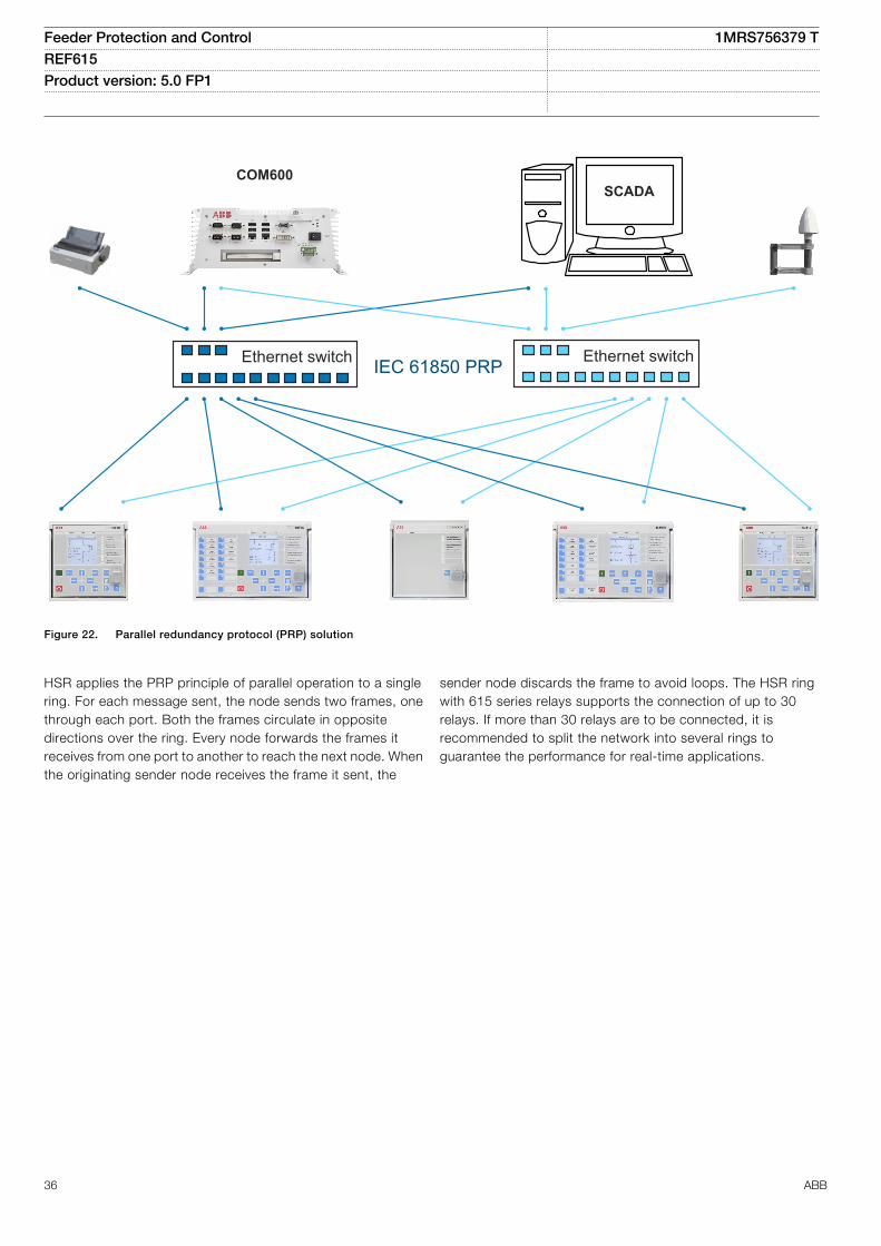
Ethernet switchIEC 61850 PRPEthernet switch
SCADACOM600
GUID-334D26B1-C3BD-47B6-BD9D-2301190A5E9D V2 EN
Figure 22. Parallel redundancy protocol (PRP) solution
HSR applies the PRP principle of parallel operation to a singlering. For each message sent, the node sends two frames, onethrough each port. Both the frames circulate in oppositedirections over the ring. Every node forwards the frames itreceives from one port to another to reach the next node. Whenthe originating sender node receives the frame it sent, the
sender node discards the frame to avoid loops. The HSR ringwith 615 series relays supports the connection of up to 30relays. If more than 30 relays are to be connected, it isrecommended to split the network into several rings toguarantee the performance for real-time applications.
Feeder Protection and Control 1MRS756379 TREF615 Product version: 5.0 FP1
36 ABB
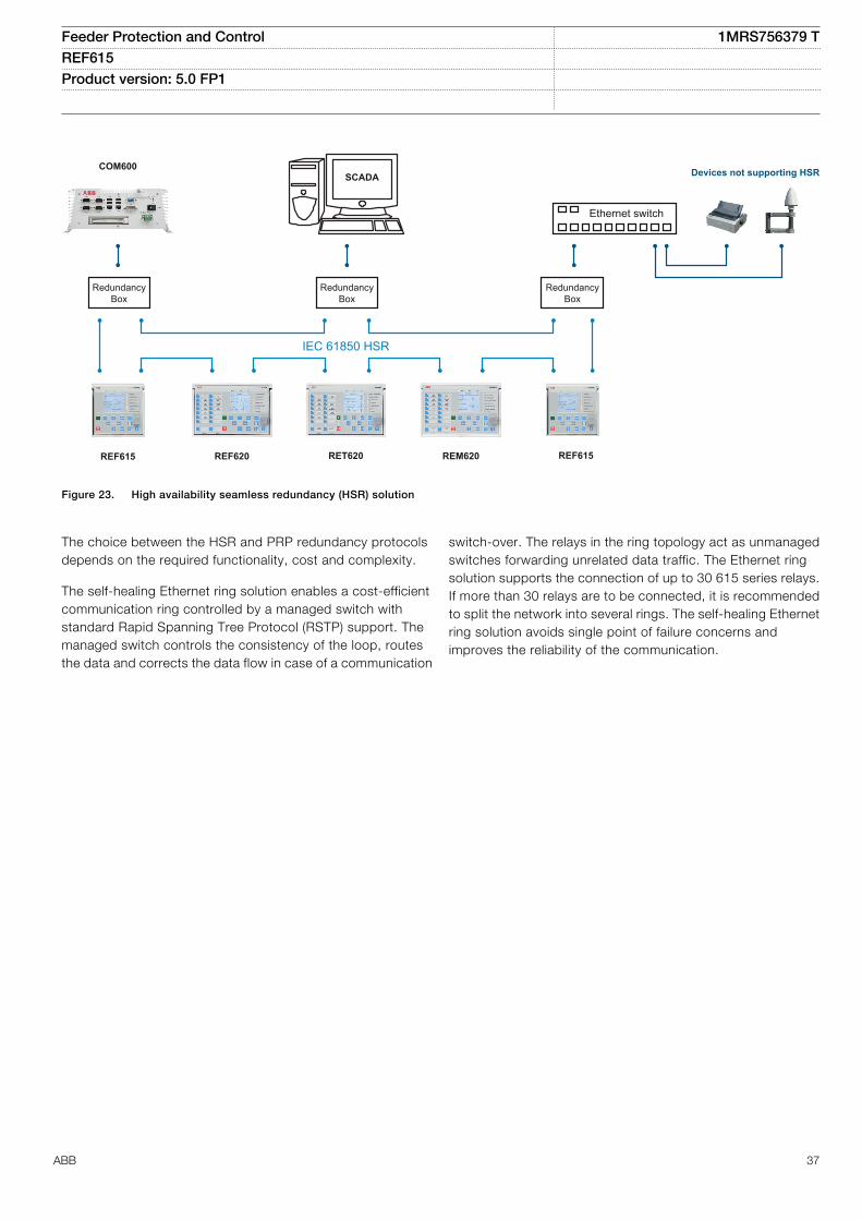
Ethernet switch
RedundancyBox
IEC 61850 HSR
RedundancyBox
RedundancyBox
REF615 REF620 RET620 REM620 REF615
SCADA Devices not supporting HSRCOM600
GUID-7996332D-7FC8-49F3-A4FE-FB4ABB730405 V1 EN
Figure 23. High availability seamless redundancy (HSR) solution
The choice between the HSR and PRP redundancy protocolsdepends on the required functionality, cost and complexity.
The self-healing Ethernet ring solution enables a cost-efficientcommunication ring controlled by a managed switch withstandard Rapid Spanning Tree Protocol (RSTP) support. Themanaged switch controls the consistency of the loop, routesthe data and corrects the data flow in case of a communication
switch-over. The relays in the ring topology act as unmanagedswitches forwarding unrelated data traffic. The Ethernet ringsolution supports the connection of up to 30 615 series relays.If more than 30 relays are to be connected, it is recommendedto split the network into several rings. The self-healing Ethernetring solution avoids single point of failure concerns andimproves the reliability of the communication.
Feeder Protection and Control 1MRS756379 TREF615 Product version: 5.0 FP1
ABB 37
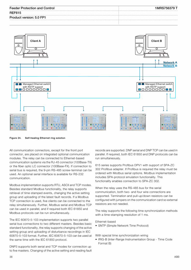
Managed Ethernet switchwith RSTP support
Managed Ethernet switchwith RSTP support
Client BClient A
Network ANetwork B
GUID-AB81C355-EF5D-4658-8AE0-01DC076E519C V4 EN
Figure 24. Self-healing Ethernet ring solution
All communication connectors, except for the front portconnector, are placed on integrated optional communicationmodules. The relay can be connected to Ethernet-basedcommunication systems via the RJ-45 connector (100Base-TX)or the fiber optic LC connector (100Base-FX). If connection toserial bus is required, the 9-pin RS-485 screw-terminal can beused. An optional serial interface is available for RS-232communication.
Modbus implementation supports RTU, ASCII and TCP modes.Besides standard Modbus functionality, the relay supportsretrieval of time-stamped events, changing the active settinggroup and uploading of the latest fault records. If a ModbusTCP connection is used, five clients can be connected to therelay simultaneously. Further, Modbus serial and Modbus TCPcan be used in parallel, and if required both IEC 61850 andModbus protocols can be run simultaneously.
The IEC 60870-5-103 implementation supports two parallelserial bus connections to two different masters. Besides basicstandard functionality, the relay supports changing of the activesetting group and uploading of disturbance recordings in IEC60870-5-103 format. Further, IEC 60870-5-103 can be used atthe same time with the IEC 61850 protocol.
DNP3 supports both serial and TCP modes for connection upto five masters. Changing of the active setting and reading fault
records are supported. DNP serial and DNP TCP can be used inparallel. If required, both IEC 61850 and DNP protocols can berun simultaneously.
615 series supports Profibus DPV1 with support of SPA-ZC302 Profibus adapter. If Profibus is required the relay must beordered with Modbus serial options. Modbus implementationincludes SPA-protocol emulation functionality. Thisfunctionality enables connection to SPA-ZC 302.
When the relay uses the RS-485 bus for the serialcommunication, both two- and four wire connections aresupported. Termination and pull-up/down resistors can beconfigured with jumpers on the communication card so externalresistors are not needed.
The relay supports the following time synchronization methodswith a time-stamping resolution of 1 ms.
Ethernet-based• SNTP (Simple Network Time Protocol)
With special time synchronization wiring• IRIG-B (Inter-Range Instrumentation Group - Time Code
Format B)
Feeder Protection and Control 1MRS756379 TREF615 Product version: 5.0 FP1
38 ABB
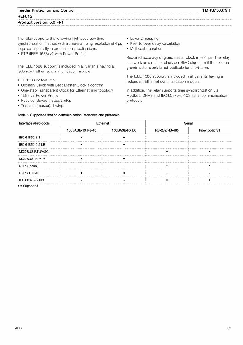
The relay supports the following high accuracy timesynchronization method with a time-stamping resolution of 4 µsrequired especially in process bus applications.• PTP (IEEE 1588) v2 with Power Profile
The IEEE 1588 support is included in all variants having aredundant Ethernet communication module.
IEEE 1588 v2 features• Ordinary Clock with Best Master Clock algorithm• One-step Transparent Clock for Ethernet ring topology• 1588 v2 Power Profile• Receive (slave): 1-step/2-step• Transmit (master): 1-step
• Layer 2 mapping• Peer to peer delay calculation• Multicast operation
Required accuracy of grandmaster clock is +/-1 µs. The relaycan work as a master clock per BMC algorithm if the externalgrandmaster clock is not available for short term.
The IEEE 1588 support is included in all variants having aredundant Ethernet communication module.
In addition, the relay supports time synchronization viaModbus, DNP3 and IEC 60870-5-103 serial communicationprotocols.
Table 5. Supported station communication interfaces and protocols
Interfaces/Protocols Ethernet Serial
100BASE-TX RJ-45 100BASE-FX LC RS-232/RS-485 Fiber optic ST
IEC 61850-8-1 - -
IEC 61850-9-2 LE - -
MODBUS RTU/ASCII - -
MODBUS TCP/IP - -
DNP3 (serial) - -
DNP3 TCP/IP - -
IEC 60870-5-103 - - = Supported
Feeder Protection and Control 1MRS756379 TREF615 Product version: 5.0 FP1
ABB 39
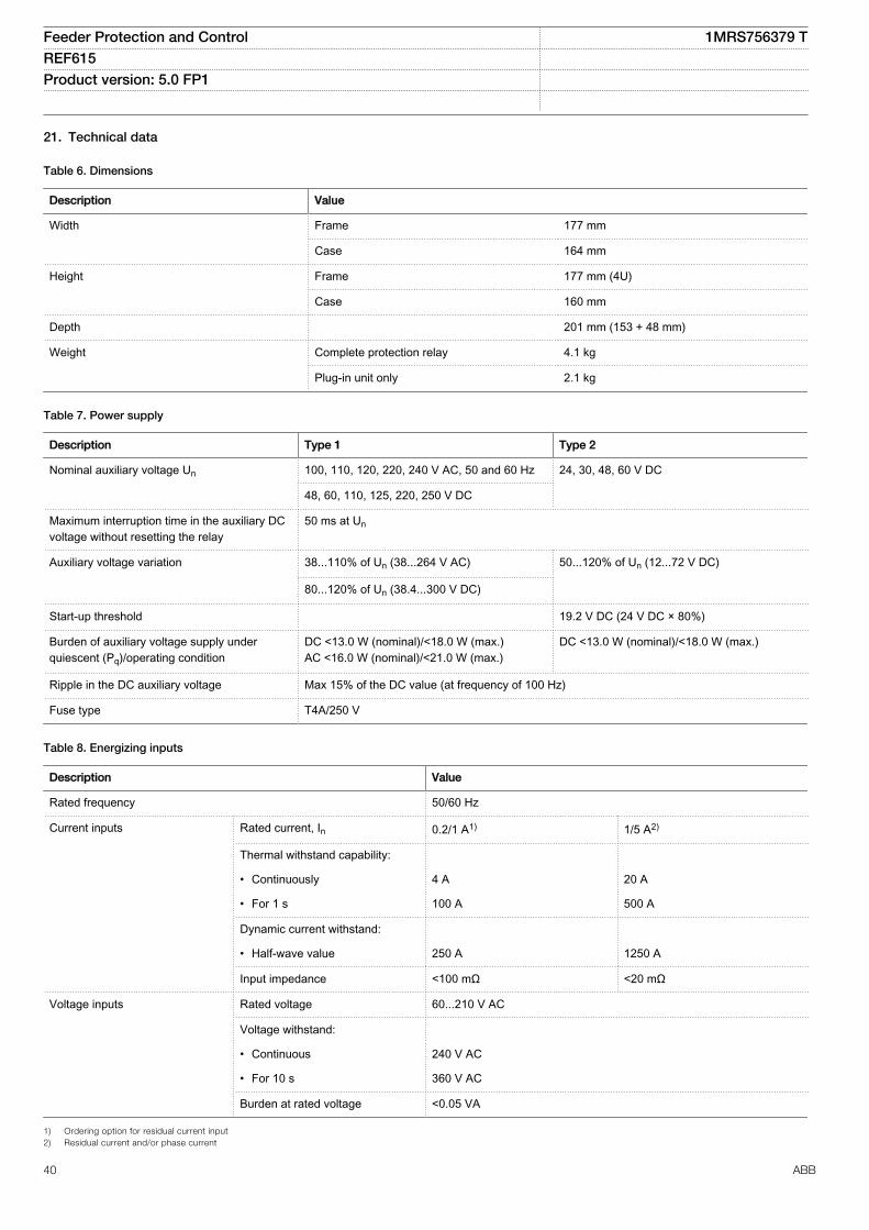
21. Technical data
Table 6. Dimensions
Description Value
Width Frame 177 mm
Case 164 mm
Height Frame 177 mm (4U)
Case 160 mm
Depth 201 mm (153 + 48 mm)
Weight Complete protection relay 4.1 kg
Plug-in unit only 2.1 kg
Table 7. Power supply
Description Type 1 Type 2
Nominal auxiliary voltage Un 100, 110, 120, 220, 240 V AC, 50 and 60 Hz 24, 30, 48, 60 V DC
48, 60, 110, 125, 220, 250 V DC
Maximum interruption time in the auxiliary DCvoltage without resetting the relay
50 ms at Un
Auxiliary voltage variation 38...110% of Un (38...264 V AC) 50...120% of Un (12...72 V DC)
80...120% of Un (38.4...300 V DC)
Start-up threshold 19.2 V DC (24 V DC × 80%)
Burden of auxiliary voltage supply underquiescent (Pq)/operating condition
DC <13.0 W (nominal)/<18.0 W (max.)AC <16.0 W (nominal)/<21.0 W (max.)
DC <13.0 W (nominal)/<18.0 W (max.)
Ripple in the DC auxiliary voltage Max 15% of the DC value (at frequency of 100 Hz)
Fuse type T4A/250 V
Table 8. Energizing inputs
Description Value
Rated frequency 50/60 Hz
Current inputs Rated current, In 0.2/1 A1) 1/5 A2)
Thermal withstand capability:
• Continuously 4 A 20 A
• For 1 s 100 A 500 A
Dynamic current withstand:
• Half-wave value 250 A 1250 A
Input impedance <100 mΩ <20 mΩ
Voltage inputs Rated voltage 60...210 V AC
Voltage withstand:
• Continuous 240 V AC
• For 10 s 360 V AC
Burden at rated voltage <0.05 VA
1) Ordering option for residual current input2) Residual current and/or phase current
Feeder Protection and Control 1MRS756379 TREF615 Product version: 5.0 FP1
40 ABB
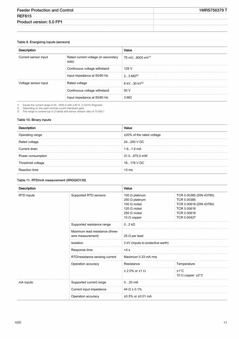
Table 9. Energizing inputs (sensors)
Description Value
Current sensor input Rated current voltage (in secondaryside)
75 mV...9000 mV1)
Continuous voltage withstand 125 V
Input impedance at 50/60 Hz 2...3 MΩ2)
Voltage sensor input Rated voltage 6 kV...30 kV3)
Continuous voltage withstand 50 V
Input impedance at 50/60 Hz 3 MΩ
1) Equals the current range of 40...4000 A with a 80 A, 3 mV/Hz Rogowski2) Depending on the used nominal current (hardware gain)3) This range is covered (up to 2*rated) with sensor division ratio of 10 000:1
Table 10. Binary inputs
Description Value
Operating range ±20% of the rated voltage
Rated voltage 24...250 V DC
Current drain 1.6...1.9 mA
Power consumption 31.0...570.0 mW
Threshold voltage 16...176 V DC
Reaction time <3 ms
Table 11. RTD/mA measurement (XRGGIO130)
Description Value
RTD inputs Supported RTD sensors 100 Ω platinum250 Ω platinum100 Ω nickel120 Ω nickel250 Ω nickel10 Ω copper
TCR 0.00385 (DIN 43760)TCR 0.00385TCR 0.00618 (DIN 43760)TCR 0.00618TCR 0.00618TCR 0.00427
Supported resistance range 0...2 kΩ
Maximum lead resistance (three-wire measurement) 25 Ω per lead
Isolation 2 kV (inputs to protective earth)
Response time <4 s
RTD/resistance sensing current Maximum 0.33 mA rms
Operation accuracy Resistance Temperature
± 2.0% or ±1 Ω ±1°C10 Ω copper: ±2°C
mA inputs Supported current range 0…20 mA
Current input impedance 44 Ω ± 0.1%
Operation accuracy ±0.5% or ±0.01 mA
Feeder Protection and Control 1MRS756379 TREF615 Product version: 5.0 FP1
ABB 41
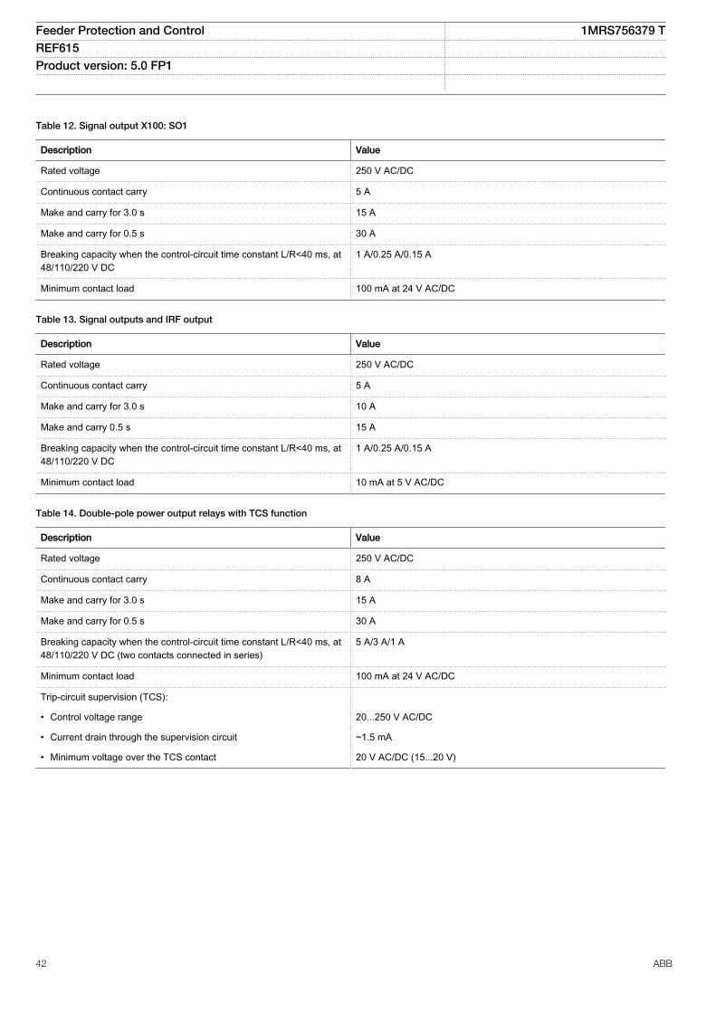
Table 12. Signal output X100: SO1
Description Value
Rated voltage 250 V AC/DC
Continuous contact carry 5 A
Make and carry for 3.0 s 15 A
Make and carry for 0.5 s 30 A
Breaking capacity when the control-circuit time constant L/R<40 ms, at48/110/220 V DC
1 A/0.25 A/0.15 A
Minimum contact load 100 mA at 24 V AC/DC
Table 13. Signal outputs and IRF output
Description Value
Rated voltage 250 V AC/DC
Continuous contact carry 5 A
Make and carry for 3.0 s 10 A
Make and carry 0.5 s 15 A
Breaking capacity when the control-circuit time constant L/R<40 ms, at48/110/220 V DC
1 A/0.25 A/0.15 A
Minimum contact load 10 mA at 5 V AC/DC
Table 14. Double-pole power output relays with TCS function
Description Value
Rated voltage 250 V AC/DC
Continuous contact carry 8 A
Make and carry for 3.0 s 15 A
Make and carry for 0.5 s 30 A
Breaking capacity when the control-circuit time constant L/R<40 ms, at48/110/220 V DC (two contacts connected in series)
5 A/3 A/1 A
Minimum contact load 100 mA at 24 V AC/DC
Trip-circuit supervision (TCS):
• Control voltage range 20...250 V AC/DC
• Current drain through the supervision circuit ~1.5 mA
• Minimum voltage over the TCS contact 20 V AC/DC (15...20 V)
Feeder Protection and Control 1MRS756379 TREF615 Product version: 5.0 FP1
42 ABB
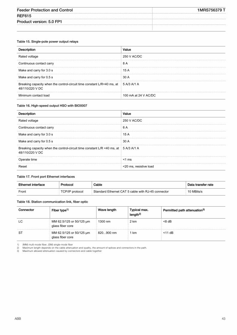
Table 15. Single-pole power output relays
Description Value
Rated voltage 250 V AC/DC
Continuous contact carry 8 A
Make and carry for 3.0 s 15 A
Make and carry for 0.5 s 30 A
Breaking capacity when the control-circuit time constant L/R<40 ms, at48/110/220 V DC
5 A/3 A/1 A
Minimum contact load 100 mA at 24 V AC/DC
Table 16. High-speed output HSO with BIO0007
Description Value
Rated voltage 250 V AC/DC
Continuous contact carry 6 A
Make and carry for 3.0 s 15 A
Make and carry for 0.5 s 30 A
Breaking capacity when the control-circuit time constant L/R <40 ms, at48/110/220 V DC
5 A/3 A/1 A
Operate time <1 ms
Reset <20 ms, resistive load
Table 17. Front port Ethernet interfaces
Ethernet interface Protocol Cable Data transfer rate
Front TCP/IP protocol Standard Ethernet CAT 5 cable with RJ-45 connector 10 MBits/s
Table 18. Station communication link, fiber optic
Connector Fiber type1) Wave length Typical max.
length2)Permitted path attenuation3)
LC MM 62.5/125 or 50/125 μmglass fiber core
1300 nm 2 km <8 dB
ST MM 62.5/125 or 50/125 μmglass fiber core
820...900 nm 1 km <11 dB
1) (MM) multi-mode fiber, (SM) single-mode fiber2) Maximum length depends on the cable attenuation and quality, the amount of splices and connectors in the path.3) Maximum allowed attenuation caused by connectors and cable together
Feeder Protection and Control 1MRS756379 TREF615 Product version: 5.0 FP1
ABB 43
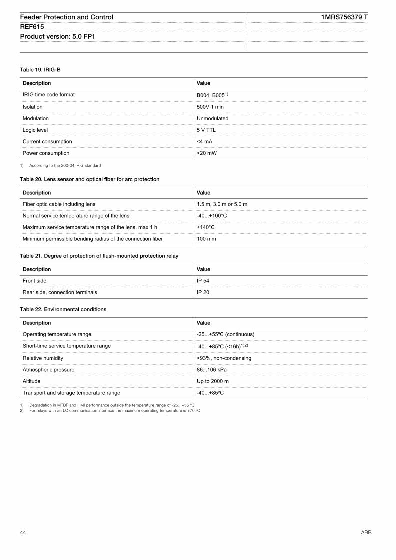
Table 19. IRIG-B
Description Value
IRIG time code format B004, B0051)
Isolation 500V 1 min
Modulation Unmodulated
Logic level 5 V TTL
Current consumption <4 mA
Power consumption <20 mW
1) According to the 200-04 IRIG standard
Table 20. Lens sensor and optical fiber for arc protection
Description Value
Fiber optic cable including lens 1.5 m, 3.0 m or 5.0 m
Normal service temperature range of the lens -40...+100°C
Maximum service temperature range of the lens, max 1 h +140°C
Minimum permissible bending radius of the connection fiber 100 mm
Table 21. Degree of protection of flush-mounted protection relay
Description Value
Front side IP 54
Rear side, connection terminals IP 20
Table 22. Environmental conditions
Description Value
Operating temperature range -25...+55ºC (continuous)
Short-time service temperature range -40...+85ºC (<16h)1)2)
Relative humidity <93%, non-condensing
Atmospheric pressure 86...106 kPa
Altitude Up to 2000 m
Transport and storage temperature range -40...+85ºC
1) Degradation in MTBF and HMI performance outside the temperature range of -25...+55 ºC2) For relays with an LC communication interface the maximum operating temperature is +70 ºC
Feeder Protection and Control 1MRS756379 TREF615 Product version: 5.0 FP1
44 ABB
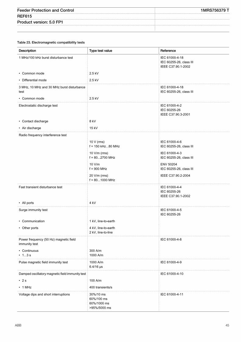
Table 23. Electromagnetic compatibility tests
Description Type test value Reference
1 MHz/100 kHz burst disturbance test IEC 61000-4-18IEC 60255-26, class IIIIEEE C37.90.1-2002
• Common mode 2.5 kV
• Differential mode 2.5 kV
3 MHz, 10 MHz and 30 MHz burst disturbancetest
IEC 61000-4-18IEC 60255-26, class III
• Common mode 2.5 kV
Electrostatic discharge test IEC 61000-4-2IEC 60255-26IEEE C37.90.3-2001
• Contact discharge 8 kV
• Air discharge 15 kV
Radio frequency interference test
10 V (rms)f = 150 kHz...80 MHz
IEC 61000-4-6IEC 60255-26, class III
10 V/m (rms)f = 80...2700 MHz
IEC 61000-4-3IEC 60255-26, class III
10 V/mf = 900 MHz
ENV 50204IEC 60255-26, class III
20 V/m (rms)f = 80...1000 MHz
IEEE C37.90.2-2004
Fast transient disturbance test IEC 61000-4-4IEC 60255-26IEEE C37.90.1-2002
• All ports 4 kV
Surge immunity test IEC 61000-4-5IEC 60255-26
• Communication 1 kV, line-to-earth
• Other ports 4 kV, line-to-earth2 kV, line-to-line
Power frequency (50 Hz) magnetic fieldimmunity test
IEC 61000-4-8
• Continuous• 1...3 s
300 A/m1000 A/m
Pulse magnetic field immunity test 1000 A/m6.4/16 µs
IEC 61000-4-9
Damped oscillatory magnetic field immunity test IEC 61000-4-10
• 2 s 100 A/m
• 1 MHz 400 transients/s
Voltage dips and short interruptions 30%/10 ms60%/100 ms60%/1000 ms>95%/5000 ms
IEC 61000-4-11
Feeder Protection and Control 1MRS756379 TREF615 Product version: 5.0 FP1
ABB 45
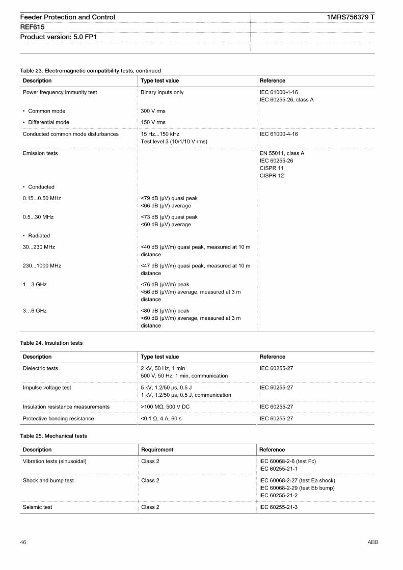
Table 23. Electromagnetic compatibility tests, continued
Description Type test value Reference
Power frequency immunity test Binary inputs only IEC 61000-4-16IEC 60255-26, class A
• Common mode 300 V rms
• Differential mode 150 V rms
Conducted common mode disturbances 15 Hz...150 kHzTest level 3 (10/1/10 V rms)
IEC 61000-4-16
Emission tests EN 55011, class AIEC 60255-26CISPR 11CISPR 12
• Conducted
0.15...0.50 MHz <79 dB (µV) quasi peak<66 dB (µV) average
0.5...30 MHz <73 dB (µV) quasi peak<60 dB (µV) average
• Radiated
30...230 MHz <40 dB (µV/m) quasi peak, measured at 10 mdistance
230...1000 MHz <47 dB (µV/m) quasi peak, measured at 10 mdistance
1…3 GHz <76 dB (µV/m) peak<56 dB (µV/m) average, measured at 3 mdistance
3…6 GHz <80 dB (µV/m) peak<60 dB (µV/m) average, measured at 3 mdistance
Table 24. Insulation tests
Description Type test value Reference
Dielectric tests 2 kV, 50 Hz, 1 min500 V, 50 Hz, 1 min, communication
IEC 60255-27
Impulse voltage test 5 kV, 1.2/50 μs, 0.5 J1 kV, 1.2/50 μs, 0.5 J, communication
IEC 60255-27
Insulation resistance measurements >100 MΩ, 500 V DC IEC 60255-27
Protective bonding resistance <0.1 Ω, 4 A, 60 s IEC 60255-27
Table 25. Mechanical tests
Description Requirement Reference
Vibration tests (sinusoidal) Class 2 IEC 60068-2-6 (test Fc)IEC 60255-21-1
Shock and bump test Class 2 IEC 60068-2-27 (test Ea shock)IEC 60068-2-29 (test Eb bump)IEC 60255-21-2
Seismic test Class 2 IEC 60255-21-3
Feeder Protection and Control 1MRS756379 TREF615 Product version: 5.0 FP1
46 ABB
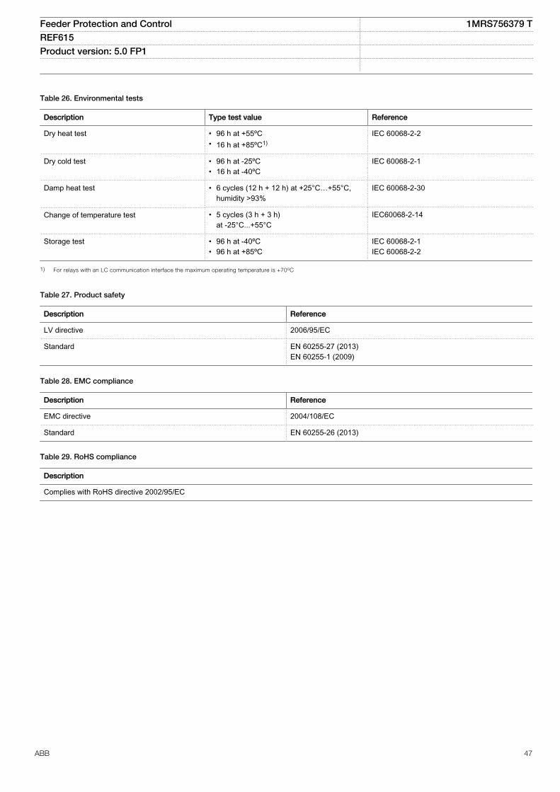
Table 26. Environmental tests
Description Type test value Reference
Dry heat test • 96 h at +55ºC• 16 h at +85ºC1)
IEC 60068-2-2
Dry cold test • 96 h at -25ºC• 16 h at -40ºC
IEC 60068-2-1
Damp heat test • 6 cycles (12 h + 12 h) at +25°C…+55°C,humidity >93%
IEC 60068-2-30
Change of temperature test • 5 cycles (3 h + 3 h)at -25°C...+55°C
IEC60068-2-14
Storage test • 96 h at -40ºC• 96 h at +85ºC
IEC 60068-2-1IEC 60068-2-2
1) For relays with an LC communication interface the maximum operating temperature is +70oC
Table 27. Product safety
Description Reference
LV directive 2006/95/EC
Standard EN 60255-27 (2013)EN 60255-1 (2009)
Table 28. EMC compliance
Description Reference
EMC directive 2004/108/EC
Standard EN 60255-26 (2013)
Table 29. RoHS compliance
Description
Complies with RoHS directive 2002/95/EC
Feeder Protection and Control 1MRS756379 TREF615 Product version: 5.0 FP1
ABB 47
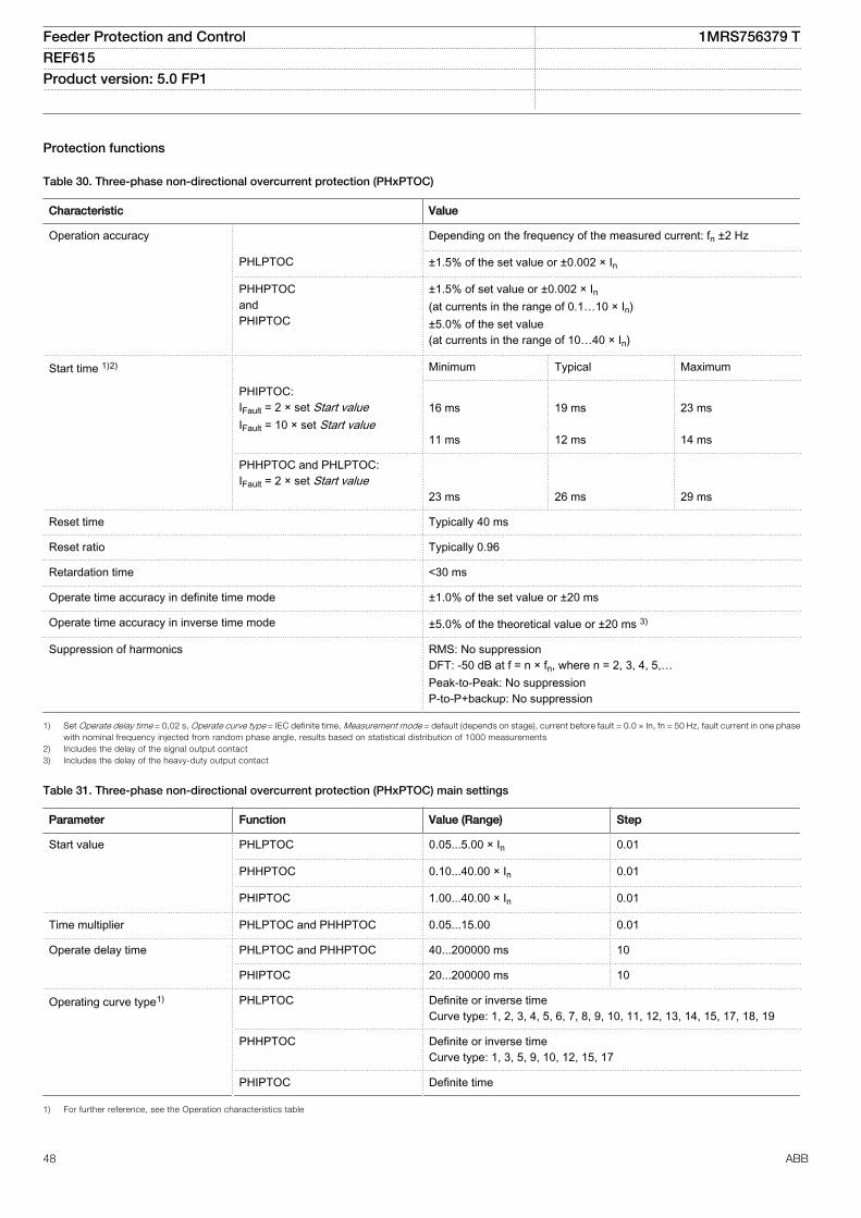
Protection functions
Table 30. Three-phase non-directional overcurrent protection (PHxPTOC)
Characteristic Value
Operation accuracy Depending on the frequency of the measured current: fn ±2 Hz
PHLPTOC ±1.5% of the set value or ±0.002 × In
PHHPTOCandPHIPTOC
±1.5% of set value or ±0.002 × In(at currents in the range of 0.1…10 × In)±5.0% of the set value(at currents in the range of 10…40 × In)
Start time 1)2) Minimum Typical Maximum
PHIPTOC:IFault = 2 × set Start valueIFault = 10 × set Start value
16 ms 11 ms
19 ms 12 ms
23 ms 14 ms
PHHPTOC and PHLPTOC:IFault = 2 × set Start value
23 ms
26 ms
29 ms
Reset time Typically 40 ms
Reset ratio Typically 0.96
Retardation time <30 ms
Operate time accuracy in definite time mode ±1.0% of the set value or ±20 ms
Operate time accuracy in inverse time mode ±5.0% of the theoretical value or ±20 ms 3)
Suppression of harmonics RMS: No suppressionDFT: -50 dB at f = n × fn, where n = 2, 3, 4, 5,…Peak-to-Peak: No suppressionP-to-P+backup: No suppression
1) Set Operate delay time = 0,02 s, Operate curve type = IEC definite time, Measurement mode = default (depends on stage), current before fault = 0.0 × In, fn = 50 Hz, fault current in one phasewith nominal frequency injected from random phase angle, results based on statistical distribution of 1000 measurements
2) Includes the delay of the signal output contact3) Includes the delay of the heavy-duty output contact
Table 31. Three-phase non-directional overcurrent protection (PHxPTOC) main settings
Parameter Function Value (Range) Step
Start value PHLPTOC 0.05...5.00 × In 0.01
PHHPTOC 0.10...40.00 × In 0.01
PHIPTOC 1.00...40.00 × In 0.01
Time multiplier PHLPTOC and PHHPTOC 0.05...15.00 0.01
Operate delay time PHLPTOC and PHHPTOC 40...200000 ms 10
PHIPTOC 20...200000 ms 10
Operating curve type1) PHLPTOC Definite or inverse timeCurve type: 1, 2, 3, 4, 5, 6, 7, 8, 9, 10, 11, 12, 13, 14, 15, 17, 18, 19
PHHPTOC Definite or inverse timeCurve type: 1, 3, 5, 9, 10, 12, 15, 17
PHIPTOC Definite time
1) For further reference, see the Operation characteristics table
Feeder Protection and Control 1MRS756379 TREF615 Product version: 5.0 FP1
48 ABB
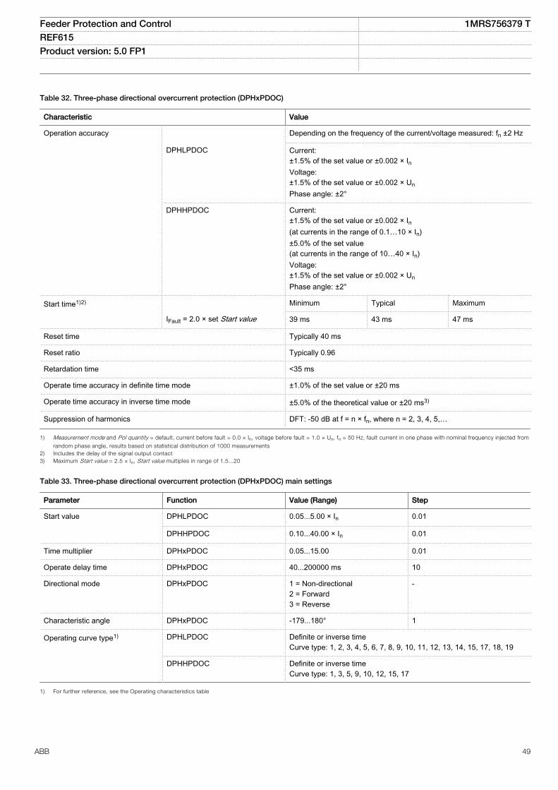
Table 32. Three-phase directional overcurrent protection (DPHxPDOC)
Characteristic Value
Operation accuracy Depending on the frequency of the current/voltage measured: fn ±2 Hz
DPHLPDOC Current:±1.5% of the set value or ±0.002 × InVoltage:±1.5% of the set value or ±0.002 × UnPhase angle: ±2°
DPHHPDOC Current:±1.5% of the set value or ±0.002 × In(at currents in the range of 0.1…10 × In)±5.0% of the set value(at currents in the range of 10…40 × In)Voltage:±1.5% of the set value or ±0.002 × UnPhase angle: ±2°
Start time1)2) Minimum Typical Maximum
IFault = 2.0 × set Start value 39 ms 43 ms 47 ms
Reset time Typically 40 ms
Reset ratio Typically 0.96
Retardation time <35 ms
Operate time accuracy in definite time mode ±1.0% of the set value or ±20 ms
Operate time accuracy in inverse time mode ±5.0% of the theoretical value or ±20 ms3)
Suppression of harmonics DFT: -50 dB at f = n × fn, where n = 2, 3, 4, 5,…
1) Measurement mode and Pol quantity = default, current before fault = 0.0 × In, voltage before fault = 1.0 × Un, fn = 50 Hz, fault current in one phase with nominal frequency injected from
random phase angle, results based on statistical distribution of 1000 measurements2) Includes the delay of the signal output contact3) Maximum Start value = 2.5 × In, Start value multiples in range of 1.5...20
Table 33. Three-phase directional overcurrent protection (DPHxPDOC) main settings
Parameter Function Value (Range) Step
Start value DPHLPDOC 0.05...5.00 × In 0.01
DPHHPDOC 0.10...40.00 × In 0.01
Time multiplier DPHxPDOC 0.05...15.00 0.01
Operate delay time DPHxPDOC 40...200000 ms 10
Directional mode DPHxPDOC 1 = Non-directional2 = Forward3 = Reverse
-
Characteristic angle DPHxPDOC -179...180° 1
Operating curve type1) DPHLPDOC Definite or inverse timeCurve type: 1, 2, 3, 4, 5, 6, 7, 8, 9, 10, 11, 12, 13, 14, 15, 17, 18, 19
DPHHPDOC Definite or inverse timeCurve type: 1, 3, 5, 9, 10, 12, 15, 17
1) For further reference, see the Operating characteristics table
Feeder Protection and Control 1MRS756379 TREF615 Product version: 5.0 FP1
ABB 49
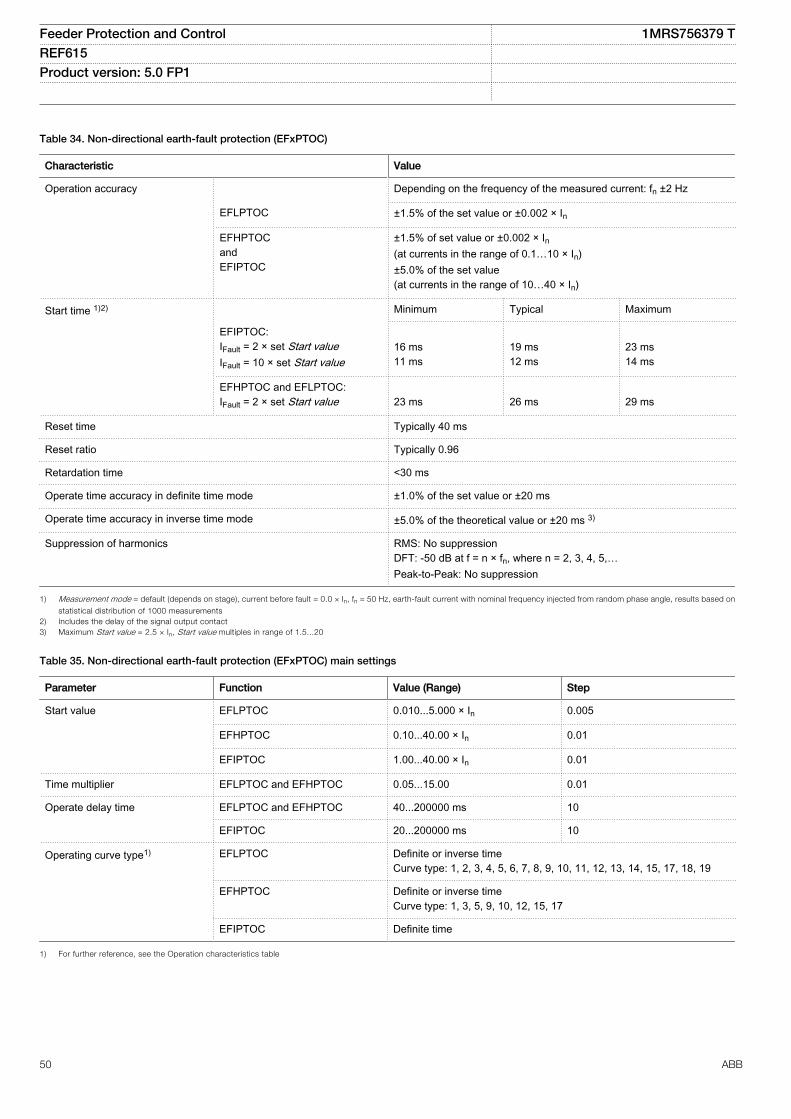
Table 34. Non-directional earth-fault protection (EFxPTOC)
Characteristic Value
Operation accuracy Depending on the frequency of the measured current: fn ±2 Hz
EFLPTOC ±1.5% of the set value or ±0.002 × In
EFHPTOCandEFIPTOC
±1.5% of set value or ±0.002 × In(at currents in the range of 0.1…10 × In)±5.0% of the set value(at currents in the range of 10…40 × In)
Start time 1)2) Minimum Typical Maximum
EFIPTOC:IFault = 2 × set Start valueIFault = 10 × set Start value
16 ms11 ms
19 ms12 ms
23 ms14 ms
EFHPTOC and EFLPTOC:IFault = 2 × set Start value
23 ms
26 ms
29 ms
Reset time Typically 40 ms
Reset ratio Typically 0.96
Retardation time <30 ms
Operate time accuracy in definite time mode ±1.0% of the set value or ±20 ms
Operate time accuracy in inverse time mode ±5.0% of the theoretical value or ±20 ms 3)
Suppression of harmonics RMS: No suppressionDFT: -50 dB at f = n × fn, where n = 2, 3, 4, 5,…Peak-to-Peak: No suppression
1) Measurement mode = default (depends on stage), current before fault = 0.0 × In, fn = 50 Hz, earth-fault current with nominal frequency injected from random phase angle, results based on
statistical distribution of 1000 measurements2) Includes the delay of the signal output contact3) Maximum Start value = 2.5 × In, Start value multiples in range of 1.5...20
Table 35. Non-directional earth-fault protection (EFxPTOC) main settings
Parameter Function Value (Range) Step
Start value EFLPTOC 0.010...5.000 × In 0.005
EFHPTOC 0.10...40.00 × In 0.01
EFIPTOC 1.00...40.00 × In 0.01
Time multiplier EFLPTOC and EFHPTOC 0.05...15.00 0.01
Operate delay time EFLPTOC and EFHPTOC 40...200000 ms 10
EFIPTOC 20...200000 ms 10
Operating curve type1) EFLPTOC Definite or inverse timeCurve type: 1, 2, 3, 4, 5, 6, 7, 8, 9, 10, 11, 12, 13, 14, 15, 17, 18, 19
EFHPTOC Definite or inverse timeCurve type: 1, 3, 5, 9, 10, 12, 15, 17
EFIPTOC Definite time
1) For further reference, see the Operation characteristics table
Feeder Protection and Control 1MRS756379 TREF615 Product version: 5.0 FP1
50 ABB
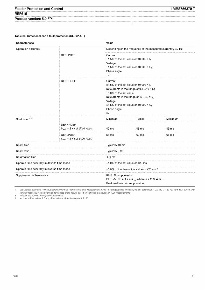
Table 36. Directional earth-fault protection (DEFxPDEF)
Characteristic Value
Operation accuracy Depending on the frequency of the measured current: fn ±2 Hz
DEFLPDEF Current:±1.5% of the set value or ±0.002 × InVoltage±1.5% of the set value or ±0.002 × UnPhase angle:±2°
DEFHPDEF Current:±1.5% of the set value or ±0.002 × In(at currents in the range of 0.1…10 × In)±5.0% of the set value(at currents in the range of 10…40 × In)Voltage:±1.5% of the set value or ±0.002 × UnPhase angle:±2°
Start time 1)2) Minimum Typical Maximum
DEFHPDEFIFault = 2 × set Start value
42 ms
46 ms
49 ms
DEFLPDEFIFault = 2 × set Start value
58 ms 62 ms 66 ms
Reset time Typically 40 ms
Reset ratio Typically 0.96
Retardation time <30 ms
Operate time accuracy in definite time mode ±1.0% of the set value or ±20 ms
Operate time accuracy in inverse time mode ±5.0% of the theoretical value or ±20 ms 3)
Suppression of harmonics RMS: No suppressionDFT: -50 dB at f = n × fn, where n = 2, 3, 4, 5,…Peak-to-Peak: No suppression
1) Set Operate delay time = 0.06 s,Operate curve type = IEC definite time, Measurement mode = default (depends on stage), current before fault = 0.0 × In, fn = 50 Hz, earth-fault current with
nominal frequency injected from random phase angle, results based on statistical distribution of 1000 measurements2) Includes the delay of the signal output contact3) Maximum Start value = 2.5 × In, Start value multiples in range of 1.5...20
Feeder Protection and Control 1MRS756379 TREF615 Product version: 5.0 FP1
ABB 51
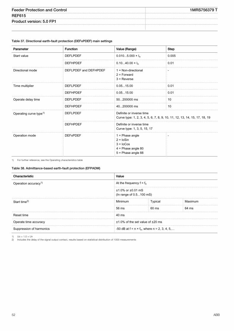
Table 37. Directional earth-fault protection (DEFxPDEF) main settings
Parameter Function Value (Range) Step
Start value DEFLPDEF 0.010...5.000 × In 0.005
DEFHPDEF 0.10...40.00 × In 0.01
Directional mode DEFLPDEF and DEFHPDEF 1 = Non-directional2 = Forward3 = Reverse
-
Time multiplier DEFLPDEF 0.05...15.00 0.01
DEFHPDEF 0.05...15.00 0.01
Operate delay time DEFLPDEF 50...200000 ms 10
DEFHPDEF 40...200000 ms 10
Operating curve type1) DEFLPDEF Definite or inverse timeCurve type: 1, 2, 3, 4, 5, 6, 7, 8, 9, 10, 11, 12, 13, 14, 15, 17, 18, 19
DEFHPDEF Definite or inverse timeCurve type: 1, 3, 5, 15, 17
Operation mode DEFxPDEF 1 = Phase angle2 = IoSin3 = IoCos4 = Phase angle 805 = Phase angle 88
-
1) For further reference, see the Operating characteristics table
Table 38. Admittance-based earth-fault protection (EFPADM)
Characteristic Value
Operation accuracy1) At the frequency f = fn
±1.0% or ±0.01 mS(In range of 0.5...100 mS)
Start time2) Minimum Typical Maximum
56 ms 60 ms 64 ms
Reset time 40 ms
Operate time accuracy ±1.0% of the set value of ±20 ms
Suppression of harmonics -50 dB at f = n × fn, where n = 2, 3, 4, 5,…
1) Uo = 1.0 × Un2) Includes the delay of the signal output contact, results based on statistical distribution of 1000 measurements
Feeder Protection and Control 1MRS756379 TREF615 Product version: 5.0 FP1
52 ABB
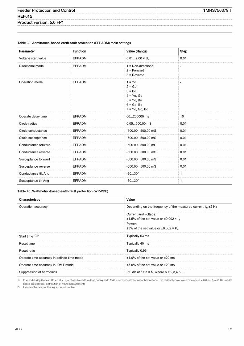
Table 39. Admittance-based earth-fault protection (EFPADM) main settings
Parameter Function Value (Range) Step
Voltage start value EFPADM 0.01...2.00 × Un 0.01
Directional mode EFPADM 1 = Non-directional2 = Forward3 = Reverse
-
Operation mode EFPADM 1 = Yo2 = Go3 = Bo4 = Yo, Go5 = Yo, Bo6 = Go, Bo7 = Yo, Go, Bo
-
Operate delay time EFPADM 60...200000 ms 10
Circle radius EFPADM 0.05...500.00 mS 0.01
Circle conductance EFPADM -500.00...500.00 mS 0.01
Circle susceptance EFPADM -500.00...500.00 mS 0.01
Conductance forward EFPADM -500.00...500.00 mS 0.01
Conductance reverse EFPADM -500.00...500.00 mS 0.01
Susceptance forward EFPADM -500.00...500.00 mS 0.01
Susceptance reverse EFPADM -500.00...500.00 mS 0.01
Conductance tilt Ang EFPADM -30...30° 1
Susceptance tilt Ang EFPADM -30...30° 1
Table 40. Wattmetric-based earth-fault protection (WPWDE)
Characteristic Value
Operation accuracy Depending on the frequency of the measured current: fn ±2 Hz
Current and voltage:±1.5% of the set value or ±0.002 × InPower:±3% of the set value or ±0.002 × Pn
Start time 1)2) Typically 63 ms
Reset time Typically 40 ms
Reset ratio Typically 0.96
Operate time accuracy in definite time mode ±1.0% of the set value or ±20 ms
Operate time accuracy in IDMT mode ±5.0% of the set value or ±20 ms
Suppression of harmonics -50 dB at f = n × fn, where n = 2,3,4,5,…
1) Io varied during the test, Uo = 1.0 × Un = phase-to-earth voltage during earth fault in compensated or unearthed network, the residual power value before fault = 0.0 pu, fn = 50 Hz, results
based on statistical distribution of 1000 measurements2) Includes the delay of the signal output contact
Feeder Protection and Control 1MRS756379 TREF615 Product version: 5.0 FP1
ABB 53
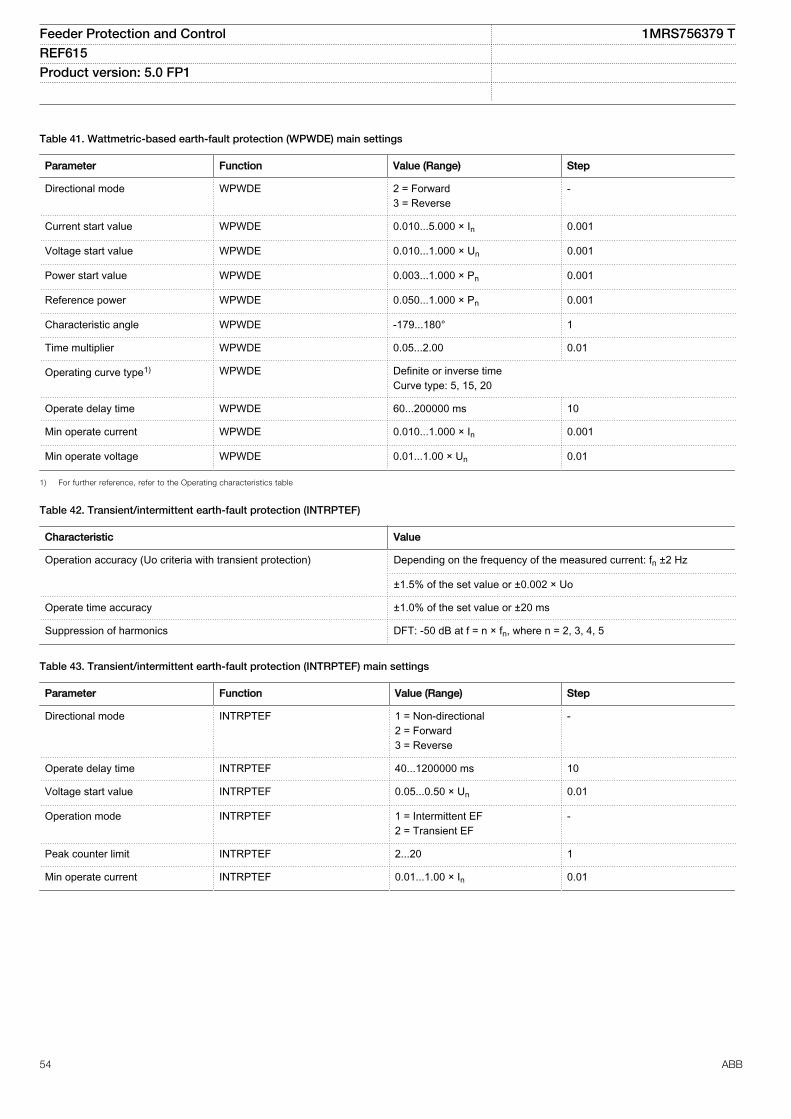
Table 41. Wattmetric-based earth-fault protection (WPWDE) main settings
Parameter Function Value (Range) Step
Directional mode WPWDE 2 = Forward3 = Reverse
-
Current start value WPWDE 0.010...5.000 × In 0.001
Voltage start value WPWDE 0.010...1.000 × Un 0.001
Power start value WPWDE 0.003...1.000 × Pn 0.001
Reference power WPWDE 0.050...1.000 × Pn 0.001
Characteristic angle WPWDE -179...180° 1
Time multiplier WPWDE 0.05...2.00 0.01
Operating curve type1) WPWDE Definite or inverse timeCurve type: 5, 15, 20
Operate delay time WPWDE 60...200000 ms 10
Min operate current WPWDE 0.010...1.000 × In 0.001
Min operate voltage WPWDE 0.01...1.00 × Un 0.01
1) For further reference, refer to the Operating characteristics table
Table 42. Transient/intermittent earth-fault protection (INTRPTEF)
Characteristic Value
Operation accuracy (Uo criteria with transient protection) Depending on the frequency of the measured current: fn ±2 Hz
±1.5% of the set value or ±0.002 × Uo
Operate time accuracy ±1.0% of the set value or ±20 ms
Suppression of harmonics DFT: -50 dB at f = n × fn, where n = 2, 3, 4, 5
Table 43. Transient/intermittent earth-fault protection (INTRPTEF) main settings
Parameter Function Value (Range) Step
Directional mode INTRPTEF 1 = Non-directional2 = Forward3 = Reverse
-
Operate delay time INTRPTEF 40...1200000 ms 10
Voltage start value INTRPTEF 0.05...0.50 × Un 0.01
Operation mode INTRPTEF 1 = Intermittent EF2 = Transient EF
-
Peak counter limit INTRPTEF 2...20 1
Min operate current INTRPTEF 0.01...1.00 × In 0.01
Feeder Protection and Control 1MRS756379 TREF615 Product version: 5.0 FP1
54 ABB
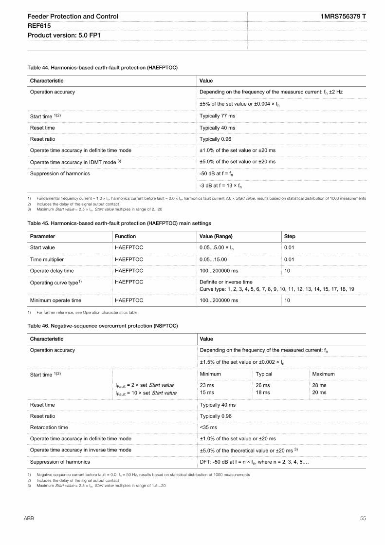
Table 44. Harmonics-based earth-fault protection (HAEFPTOC)
Characteristic Value
Operation accuracy Depending on the frequency of the measured current: fn ±2 Hz
±5% of the set value or ±0.004 × In
Start time 1)2) Typically 77 ms
Reset time Typically 40 ms
Reset ratio Typically 0.96
Operate time accuracy in definite time mode ±1.0% of the set value or ±20 ms
Operate time accuracy in IDMT mode 3) ±5.0% of the set value or ±20 ms
Suppression of harmonics -50 dB at f = fn
-3 dB at f = 13 × fn
1) Fundamental frequency current = 1.0 × In, harmonics current before fault = 0.0 × In, harmonics fault current 2.0 × Start value, results based on statistical distribution of 1000 measurements
2) Includes the delay of the signal output contact3) Maximum Start value = 2.5 × In, Start value multiples in range of 2...20
Table 45. Harmonics-based earth-fault protection (HAEFPTOC) main settings
Parameter Function Value (Range) Step
Start value HAEFPTOC 0.05...5.00 × In 0.01
Time multiplier HAEFPTOC 0.05...15.00 0.01
Operate delay time HAEFPTOC 100...200000 ms 10
Operating curve type1) HAEFPTOC Definite or inverse timeCurve type: 1, 2, 3, 4, 5, 6, 7, 8, 9, 10, 11, 12, 13, 14, 15, 17, 18, 19
Minimum operate time HAEFPTOC 100...200000 ms 10
1) For further reference, see Operation characteristics table
Table 46. Negative-sequence overcurrent protection (NSPTOC)
Characteristic Value
Operation accuracy Depending on the frequency of the measured current: fn
±1.5% of the set value or ±0.002 × In
Start time 1)2) Minimum Typical Maximum
IFault = 2 × set Start valueIFault = 10 × set Start value
23 ms15 ms
26 ms18 ms
28 ms20 ms
Reset time Typically 40 ms
Reset ratio Typically 0.96
Retardation time <35 ms
Operate time accuracy in definite time mode ±1.0% of the set value or ±20 ms
Operate time accuracy in inverse time mode ±5.0% of the theoretical value or ±20 ms 3)
Suppression of harmonics DFT: -50 dB at f = n × fn, where n = 2, 3, 4, 5,…
1) Negative sequence current before fault = 0.0, fn = 50 Hz, results based on statistical distribution of 1000 measurements
2) Includes the delay of the signal output contact3) Maximum Start value = 2.5 × In, Start value multiples in range of 1.5...20
Feeder Protection and Control 1MRS756379 TREF615 Product version: 5.0 FP1
ABB 55
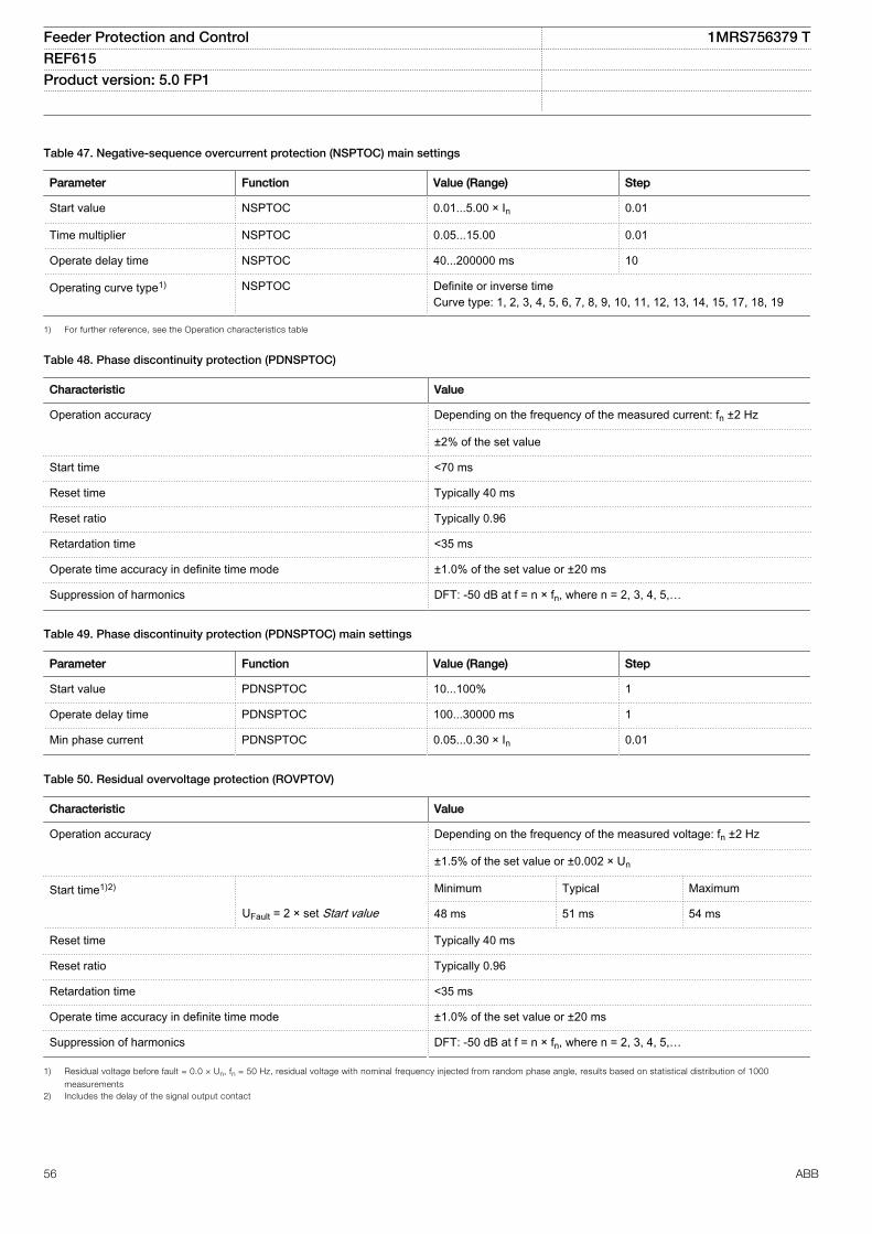
Table 47. Negative-sequence overcurrent protection (NSPTOC) main settings
Parameter Function Value (Range) Step
Start value NSPTOC 0.01...5.00 × In 0.01
Time multiplier NSPTOC 0.05...15.00 0.01
Operate delay time NSPTOC 40...200000 ms 10
Operating curve type1) NSPTOC Definite or inverse timeCurve type: 1, 2, 3, 4, 5, 6, 7, 8, 9, 10, 11, 12, 13, 14, 15, 17, 18, 19
1) For further reference, see the Operation characteristics table
Table 48. Phase discontinuity protection (PDNSPTOC)
Characteristic Value
Operation accuracy Depending on the frequency of the measured current: fn ±2 Hz
±2% of the set value
Start time <70 ms
Reset time Typically 40 ms
Reset ratio Typically 0.96
Retardation time <35 ms
Operate time accuracy in definite time mode ±1.0% of the set value or ±20 ms
Suppression of harmonics DFT: -50 dB at f = n × fn, where n = 2, 3, 4, 5,…
Table 49. Phase discontinuity protection (PDNSPTOC) main settings
Parameter Function Value (Range) Step
Start value PDNSPTOC 10...100% 1
Operate delay time PDNSPTOC 100...30000 ms 1
Min phase current PDNSPTOC 0.05...0.30 × In 0.01
Table 50. Residual overvoltage protection (ROVPTOV)
Characteristic Value
Operation accuracy Depending on the frequency of the measured voltage: fn ±2 Hz
±1.5% of the set value or ±0.002 × Un
Start time1)2) Minimum Typical Maximum
UFault = 2 × set Start value 48 ms 51 ms 54 ms
Reset time Typically 40 ms
Reset ratio Typically 0.96
Retardation time <35 ms
Operate time accuracy in definite time mode ±1.0% of the set value or ±20 ms
Suppression of harmonics DFT: -50 dB at f = n × fn, where n = 2, 3, 4, 5,…
1) Residual voltage before fault = 0.0 × Un, fn = 50 Hz, residual voltage with nominal frequency injected from random phase angle, results based on statistical distribution of 1000
measurements2) Includes the delay of the signal output contact
Feeder Protection and Control 1MRS756379 TREF615 Product version: 5.0 FP1
56 ABB
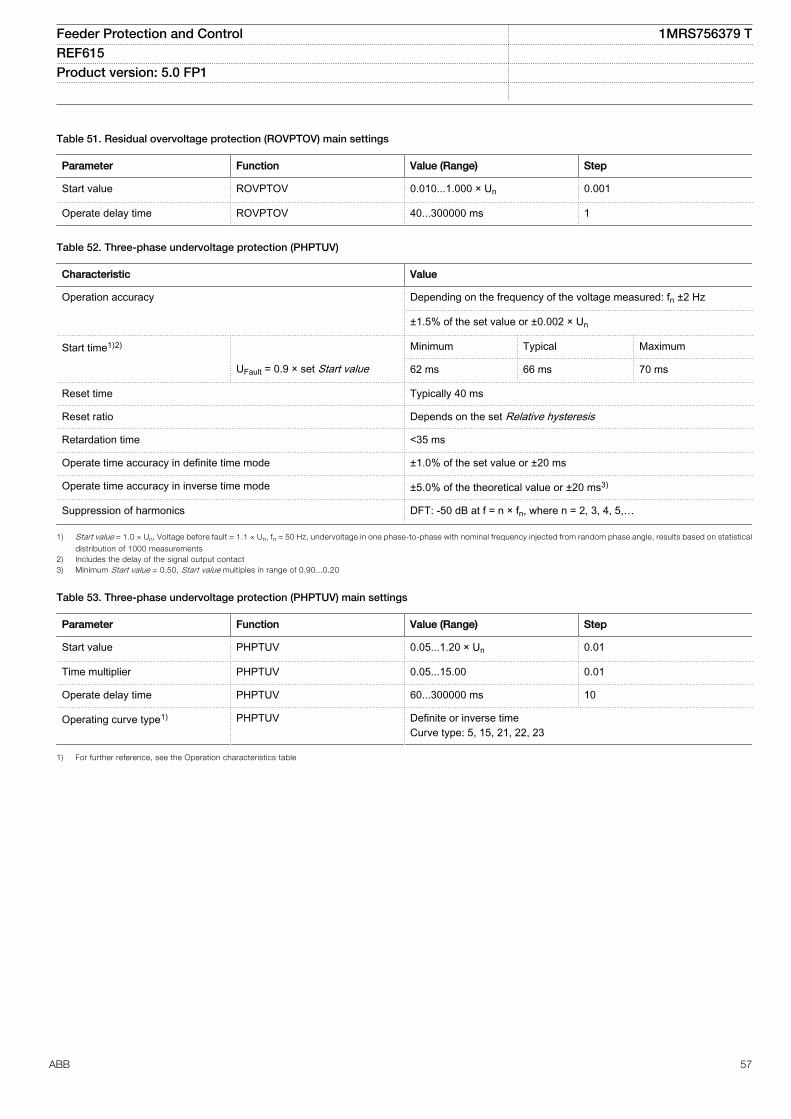
Table 51. Residual overvoltage protection (ROVPTOV) main settings
Parameter Function Value (Range) Step
Start value ROVPTOV 0.010...1.000 × Un 0.001
Operate delay time ROVPTOV 40...300000 ms 1
Table 52. Three-phase undervoltage protection (PHPTUV)
Characteristic Value
Operation accuracy Depending on the frequency of the voltage measured: fn ±2 Hz
±1.5% of the set value or ±0.002 × Un
Start time1)2) Minimum Typical Maximum
UFault = 0.9 × set Start value 62 ms 66 ms 70 ms
Reset time Typically 40 ms
Reset ratio Depends on the set Relative hysteresis
Retardation time <35 ms
Operate time accuracy in definite time mode ±1.0% of the set value or ±20 ms
Operate time accuracy in inverse time mode ±5.0% of the theoretical value or ±20 ms3)
Suppression of harmonics DFT: -50 dB at f = n × fn, where n = 2, 3, 4, 5,…
1) Start value = 1.0 × Un, Voltage before fault = 1.1 × Un, fn = 50 Hz, undervoltage in one phase-to-phase with nominal frequency injected from random phase angle, results based on statistical
distribution of 1000 measurements2) Includes the delay of the signal output contact3) Minimum Start value = 0.50, Start value multiples in range of 0.90...0.20
Table 53. Three-phase undervoltage protection (PHPTUV) main settings
Parameter Function Value (Range) Step
Start value PHPTUV 0.05...1.20 × Un 0.01
Time multiplier PHPTUV 0.05...15.00 0.01
Operate delay time PHPTUV 60...300000 ms 10
Operating curve type1) PHPTUV Definite or inverse timeCurve type: 5, 15, 21, 22, 23
1) For further reference, see the Operation characteristics table
Feeder Protection and Control 1MRS756379 TREF615 Product version: 5.0 FP1
ABB 57
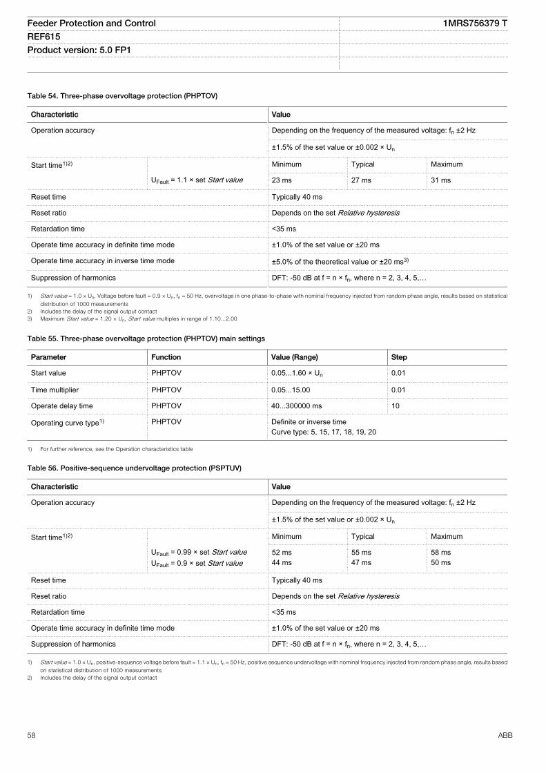
Table 54. Three-phase overvoltage protection (PHPTOV)
Characteristic Value
Operation accuracy Depending on the frequency of the measured voltage: fn ±2 Hz
±1.5% of the set value or ±0.002 × Un
Start time1)2) Minimum Typical Maximum
UFault = 1.1 × set Start value 23 ms 27 ms 31 ms
Reset time Typically 40 ms
Reset ratio Depends on the set Relative hysteresis
Retardation time <35 ms
Operate time accuracy in definite time mode ±1.0% of the set value or ±20 ms
Operate time accuracy in inverse time mode ±5.0% of the theoretical value or ±20 ms3)
Suppression of harmonics DFT: -50 dB at f = n × fn, where n = 2, 3, 4, 5,…
1) Start value = 1.0 × Un, Voltage before fault = 0.9 × Un, fn = 50 Hz, overvoltage in one phase-to-phase with nominal frequency injected from random phase angle, results based on statistical
distribution of 1000 measurements2) Includes the delay of the signal output contact3) Maximum Start value = 1.20 × Un, Start value multiples in range of 1.10...2.00
Table 55. Three-phase overvoltage protection (PHPTOV) main settings
Parameter Function Value (Range) Step
Start value PHPTOV 0.05...1.60 × Un 0.01
Time multiplier PHPTOV 0.05...15.00 0.01
Operate delay time PHPTOV 40...300000 ms 10
Operating curve type1) PHPTOV Definite or inverse timeCurve type: 5, 15, 17, 18, 19, 20
1) For further reference, see the Operation characteristics table
Table 56. Positive-sequence undervoltage protection (PSPTUV)
Characteristic Value
Operation accuracy Depending on the frequency of the measured voltage: fn ±2 Hz
±1.5% of the set value or ±0.002 × Un
Start time1)2) Minimum Typical Maximum
UFault = 0.99 × set Start valueUFault = 0.9 × set Start value
52 ms44 ms
55 ms47 ms
58 ms50 ms
Reset time Typically 40 ms
Reset ratio Depends on the set Relative hysteresis
Retardation time <35 ms
Operate time accuracy in definite time mode ±1.0% of the set value or ±20 ms
Suppression of harmonics DFT: -50 dB at f = n × fn, where n = 2, 3, 4, 5,…
1) Start value = 1.0 × Un, positive-sequence voltage before fault = 1.1 × Un, fn = 50 Hz, positive sequence undervoltage with nominal frequency injected from random phase angle, results based
on statistical distribution of 1000 measurements2) Includes the delay of the signal output contact
Feeder Protection and Control 1MRS756379 TREF615 Product version: 5.0 FP1
58 ABB
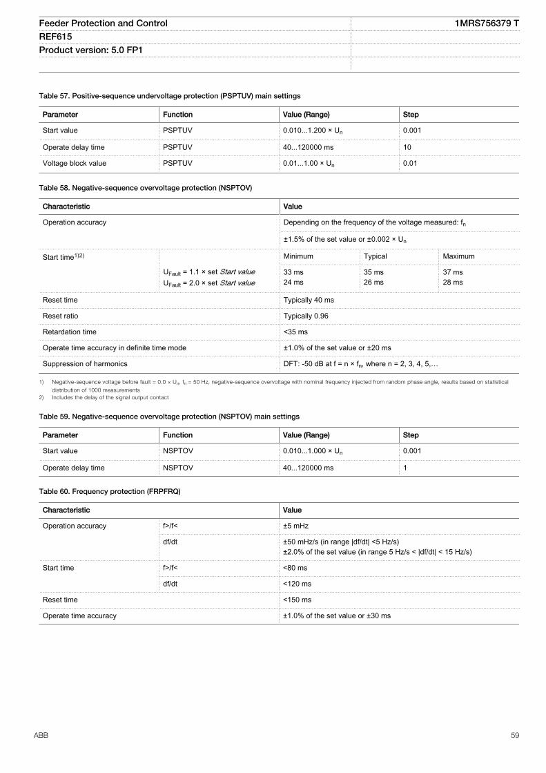
Table 57. Positive-sequence undervoltage protection (PSPTUV) main settings
Parameter Function Value (Range) Step
Start value PSPTUV 0.010...1.200 × Un 0.001
Operate delay time PSPTUV 40...120000 ms 10
Voltage block value PSPTUV 0.01...1.00 × Un 0.01
Table 58. Negative-sequence overvoltage protection (NSPTOV)
Characteristic Value
Operation accuracy Depending on the frequency of the voltage measured: fn
±1.5% of the set value or ±0.002 × Un
Start time1)2) Minimum Typical Maximum
UFault = 1.1 × set Start valueUFault = 2.0 × set Start value
33 ms24 ms
35 ms26 ms
37 ms28 ms
Reset time Typically 40 ms
Reset ratio Typically 0.96
Retardation time <35 ms
Operate time accuracy in definite time mode ±1.0% of the set value or ±20 ms
Suppression of harmonics DFT: -50 dB at f = n × fn, where n = 2, 3, 4, 5,…
1) Negative-sequence voltage before fault = 0.0 × Un, fn = 50 Hz, negative-sequence overvoltage with nominal frequency injected from random phase angle, results based on statistical
distribution of 1000 measurements2) Includes the delay of the signal output contact
Table 59. Negative-sequence overvoltage protection (NSPTOV) main settings
Parameter Function Value (Range) Step
Start value NSPTOV 0.010...1.000 × Un 0.001
Operate delay time NSPTOV 40...120000 ms 1
Table 60. Frequency protection (FRPFRQ)
Characteristic Value
Operation accuracy f>/f< ±5 mHz
df/dt ±50 mHz/s (in range |df/dt| <5 Hz/s)±2.0% of the set value (in range 5 Hz/s < |df/dt| < 15 Hz/s)
Start time f>/f< <80 ms
df/dt <120 ms
Reset time <150 ms
Operate time accuracy ±1.0% of the set value or ±30 ms
Feeder Protection and Control 1MRS756379 TREF615 Product version: 5.0 FP1
ABB 59
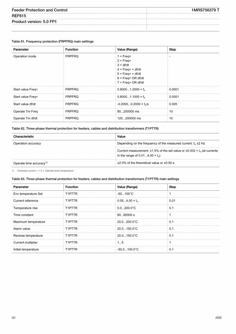
Table 61. Frequency protection (FRPFRQ) main settings
Parameter Function Value (Range) Step
Operation mode FRPFRQ 1 = Freq<2 = Freq>3 = df/dt4 = Freq< + df/dt5 = Freq> + df/dt6 = Freq< OR df/dt7 = Freq> OR df/dt
-
Start value Freq> FRPFRQ 0.9000...1.2000 × fn 0.0001
Start value Freq< FRPFRQ 0.8000...1.1000 × fn 0.0001
Start value df/dt FRPFRQ -0.2000...0.2000 × fn/s 0.005
Operate Tm Freq FRPFRQ 80...200000 ms 10
Operate Tm df/dt FRPFRQ 120...200000 ms 10
Table 62. Three-phase thermal protection for feeders, cables and distribution transformers (T1PTTR)
Characteristic Value
Operation accuracy Depending on the frequency of the measured current: fn ±2 Hz
Current measurement: ±1.5% of the set value or ±0.002 × In (at currentsin the range of 0.01...4.00 × In)
Operate time accuracy1) ±2.0% of the theoretical value or ±0.50 s
1) Overload current > 1.2 × Operate level temperature
Table 63. Three-phase thermal protection for feeders, cables and distribution transformers (T1PTTR) main settings
Parameter Function Value (Range) Step
Env temperature Set T1PTTR -50...100°C 1
Current reference T1PTTR 0.05...4.00 × In 0.01
Temperature rise T1PTTR 0.0...200.0°C 0.1
Time constant T1PTTR 60...60000 s 1
Maximum temperature T1PTTR 20.0...200.0°C 0.1
Alarm value T1PTTR 20.0...150.0°C 0.1
Reclose temperature T1PTTR 20.0...150.0°C 0.1
Current multiplier T1PTTR 1...5 1
Initial temperature T1PTTR -50.0...100.0°C 0.1
Feeder Protection and Control 1MRS756379 TREF615 Product version: 5.0 FP1
60 ABB
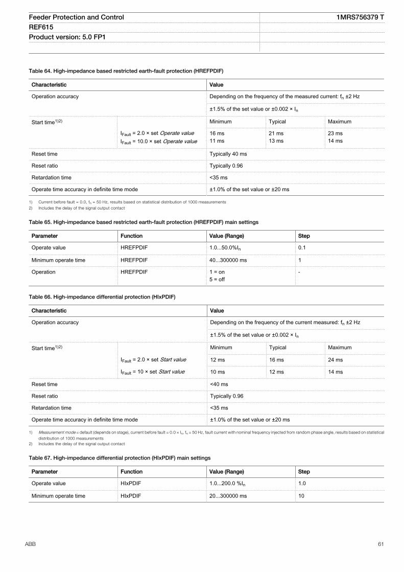
Table 64. High-impedance based restricted earth-fault protection (HREFPDIF)
Characteristic Value
Operation accuracy Depending on the frequency of the measured current: fn ±2 Hz
±1.5% of the set value or ±0.002 × In
Start time1)2) Minimum Typical Maximum
IFault = 2.0 × set Operate valueIFault = 10.0 × set Operate value
16 ms11 ms
21 ms13 ms
23 ms14 ms
Reset time Typically 40 ms
Reset ratio Typically 0.96
Retardation time <35 ms
Operate time accuracy in definite time mode ±1.0% of the set value or ±20 ms
1) Current before fault = 0.0, fn = 50 Hz, results based on statistical distribution of 1000 measurements
2) Includes the delay of the signal output contact
Table 65. High-impedance based restricted earth-fault protection (HREFPDIF) main settings
Parameter Function Value (Range) Step
Operate value HREFPDIF 1.0...50.0%In 0.1
Minimum operate time HREFPDIF 40...300000 ms 1
Operation HREFPDIF 1 = on5 = off
-
Table 66. High-impedance differential protection (HIxPDIF)
Characteristic Value
Operation accuracy Depending on the frequency of the current measured: fn ±2 Hz
±1.5% of the set value or ±0.002 × In
Start time1)2) Minimum Typical Maximum
IFault = 2.0 × set Start value 12 ms 16 ms 24 ms
IFault = 10 × set Start value 10 ms 12 ms 14 ms
Reset time <40 ms
Reset ratio Typically 0.96
Retardation time <35 ms
Operate time accuracy in definite time mode ±1.0% of the set value or ±20 ms
1) Measurement mode = default (depends on stage), current before fault = 0.0 × In, fn = 50 Hz, fault current with nominal frequency injected from random phase angle, results based on statistical
distribution of 1000 measurements2) Includes the delay of the signal output contact
Table 67. High-impedance differential protection (HIxPDIF) main settings
Parameter Function Value (Range) Step
Operate value HIxPDIF 1.0...200.0 %In 1.0
Minimum operate time HIxPDIF 20...300000 ms 10
Feeder Protection and Control 1MRS756379 TREF615 Product version: 5.0 FP1
ABB 61
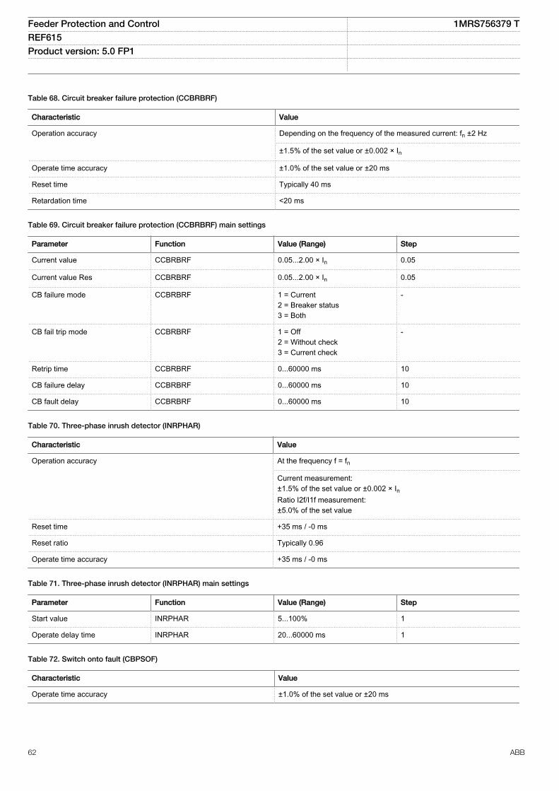
Table 68. Circuit breaker failure protection (CCBRBRF)
Characteristic Value
Operation accuracy Depending on the frequency of the measured current: fn ±2 Hz
±1.5% of the set value or ±0.002 × In
Operate time accuracy ±1.0% of the set value or ±20 ms
Reset time Typically 40 ms
Retardation time <20 ms
Table 69. Circuit breaker failure protection (CCBRBRF) main settings
Parameter Function Value (Range) Step
Current value CCBRBRF 0.05...2.00 × In 0.05
Current value Res CCBRBRF 0.05...2.00 × In 0.05
CB failure mode CCBRBRF 1 = Current2 = Breaker status3 = Both
-
CB fail trip mode CCBRBRF 1 = Off2 = Without check3 = Current check
-
Retrip time CCBRBRF 0...60000 ms 10
CB failure delay CCBRBRF 0...60000 ms 10
CB fault delay CCBRBRF 0...60000 ms 10
Table 70. Three-phase inrush detector (INRPHAR)
Characteristic Value
Operation accuracy At the frequency f = fn
Current measurement:±1.5% of the set value or ±0.002 × InRatio I2f/I1f measurement:±5.0% of the set value
Reset time +35 ms / -0 ms
Reset ratio Typically 0.96
Operate time accuracy +35 ms / -0 ms
Table 71. Three-phase inrush detector (INRPHAR) main settings
Parameter Function Value (Range) Step
Start value INRPHAR 5...100% 1
Operate delay time INRPHAR 20...60000 ms 1
Table 72. Switch onto fault (CBPSOF)
Characteristic Value
Operate time accuracy ±1.0% of the set value or ±20 ms
Feeder Protection and Control 1MRS756379 TREF615 Product version: 5.0 FP1
62 ABB
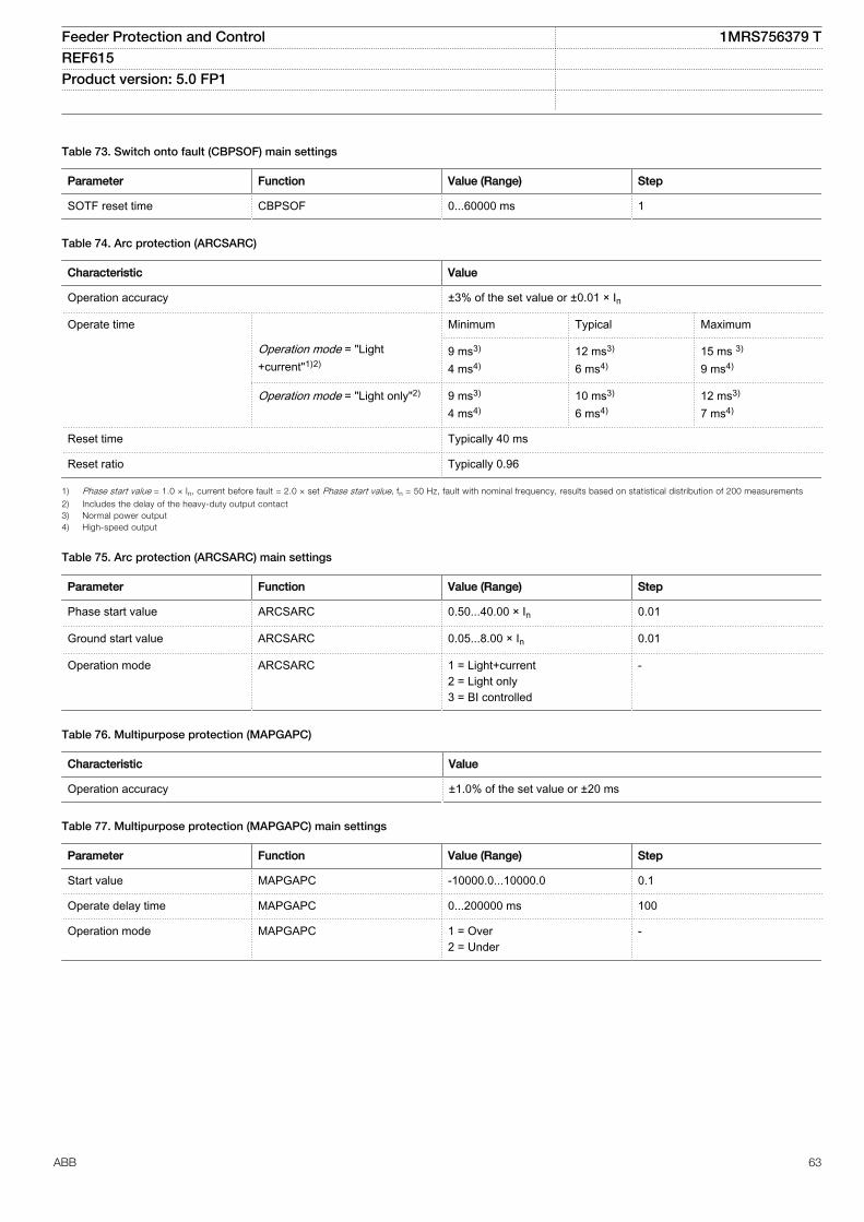
Table 73. Switch onto fault (CBPSOF) main settings
Parameter Function Value (Range) Step
SOTF reset time CBPSOF 0...60000 ms 1
Table 74. Arc protection (ARCSARC)
Characteristic Value
Operation accuracy ±3% of the set value or ±0.01 × In
Operate time Minimum Typical Maximum
Operation mode = "Light+current"1)2)
9 ms3)
4 ms4)12 ms3)
6 ms4)15 ms 3)
9 ms4)
Operation mode = "Light only"2) 9 ms3)
4 ms4)10 ms3)
6 ms4)12 ms3)
7 ms4)
Reset time Typically 40 ms
Reset ratio Typically 0.96
1) Phase start value = 1.0 × In, current before fault = 2.0 × set Phase start value, fn = 50 Hz, fault with nominal frequency, results based on statistical distribution of 200 measurements
2) Includes the delay of the heavy-duty output contact3) Normal power output4) High-speed output
Table 75. Arc protection (ARCSARC) main settings
Parameter Function Value (Range) Step
Phase start value ARCSARC 0.50...40.00 × In 0.01
Ground start value ARCSARC 0.05...8.00 × In 0.01
Operation mode ARCSARC 1 = Light+current2 = Light only3 = BI controlled
-
Table 76. Multipurpose protection (MAPGAPC)
Characteristic Value
Operation accuracy ±1.0% of the set value or ±20 ms
Table 77. Multipurpose protection (MAPGAPC) main settings
Parameter Function Value (Range) Step
Start value MAPGAPC -10000.0...10000.0 0.1
Operate delay time MAPGAPC 0...200000 ms 100
Operation mode MAPGAPC 1 = Over2 = Under
-
Feeder Protection and Control 1MRS756379 TREF615 Product version: 5.0 FP1
ABB 63
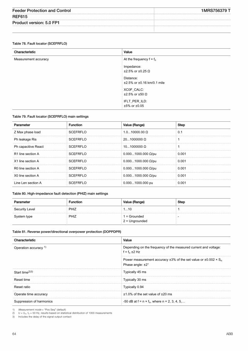
Table 78. Fault locator (SCEFRFLO)
Characteristic Value
Measurement accuracy At the frequency f = fn
Impedance:±2.5% or ±0.25 Ω
Distance:±2.5% or ±0.16 km/0.1 mile
XC0F_CALC:±2.5% or ±50 Ω
IFLT_PER_ILD:±5% or ±0.05
Table 79. Fault locator (SCEFRFLO) main settings
Parameter Function Value (Range) Step
Z Max phase load SCEFRFLO 1.0...10000.00 Ω 0.1
Ph leakage Ris SCEFRFLO 20...1000000 Ω 1
Ph capacitive React SCEFRFLO 10...1000000 Ω 1
R1 line section A SCEFRFLO 0.000...1000.000 Ω/pu 0.001
X1 line section A SCEFRFLO 0.000...1000.000 Ω/pu 0.001
R0 line section A SCEFRFLO 0.000...1000.000 Ω/pu 0.001
X0 line section A SCEFRFLO 0.000...1000.000 Ω/pu 0.001
Line Len section A SCEFRFLO 0.000...1000.000 pu 0.001
Table 80. High-impedance fault detection (PHIZ) main settings
Parameter Function Value (Range) Step
Security Level PHIZ 1...10 1
System type PHIZ 1 = Grounded2 = Ungrounded
-
Table 81. Reverse power/directional overpower protection (DOPPDPR)
Characteristic Value
Operation accuracy 1)
Depending on the frequency of the measured current and voltage:f = fn ±2 Hz
Power measurement accuracy ±3% of the set value or ±0.002 × SnPhase angle: ±2°
Start time2)3) Typically 45 ms
Reset time Typically 30 ms
Reset ratio Typically 0.94
Operate time accuracy ±1.0% of the set value of ±20 ms
Suppression of harmonics -50 dB at f = n × fn, where n = 2, 3, 4, 5,…
1) Measurement mode = “Pos Seq” (default)2) U = Un, fn = 50 Hz, results based on statistical distribution of 1000 measurements
3) Includes the delay of the signal output contact
Feeder Protection and Control 1MRS756379 TREF615 Product version: 5.0 FP1
64 ABB
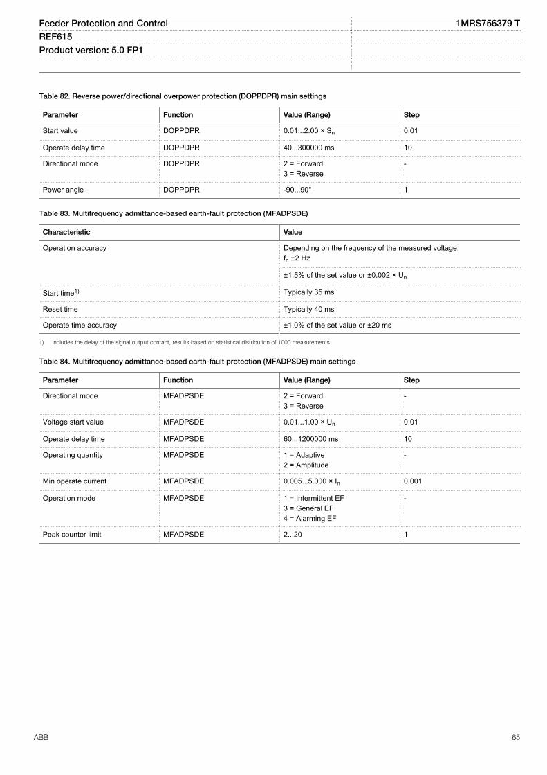
Table 82. Reverse power/directional overpower protection (DOPPDPR) main settings
Parameter Function Value (Range) Step
Start value DOPPDPR 0.01...2.00 × Sn 0.01
Operate delay time DOPPDPR 40...300000 ms 10
Directional mode DOPPDPR 2 = Forward3 = Reverse
-
Power angle DOPPDPR -90...90° 1
Table 83. Multifrequency admittance-based earth-fault protection (MFADPSDE)
Characteristic Value
Operation accuracy Depending on the frequency of the measured voltage:fn ±2 Hz
±1.5% of the set value or ±0.002 × Un
Start time1) Typically 35 ms
Reset time Typically 40 ms
Operate time accuracy ±1.0% of the set value or ±20 ms
1) Includes the delay of the signal output contact, results based on statistical distribution of 1000 measurements
Table 84. Multifrequency admittance-based earth-fault protection (MFADPSDE) main settings
Parameter Function Value (Range) Step
Directional mode MFADPSDE 2 = Forward3 = Reverse
-
Voltage start value MFADPSDE 0.01...1.00 × Un 0.01
Operate delay time MFADPSDE 60...1200000 ms 10
Operating quantity MFADPSDE 1 = Adaptive2 = Amplitude
-
Min operate current MFADPSDE 0.005...5.000 × In 0.001
Operation mode MFADPSDE 1 = Intermittent EF3 = General EF4 = Alarming EF
-
Peak counter limit MFADPSDE 2...20 1
Feeder Protection and Control 1MRS756379 TREF615 Product version: 5.0 FP1
ABB 65
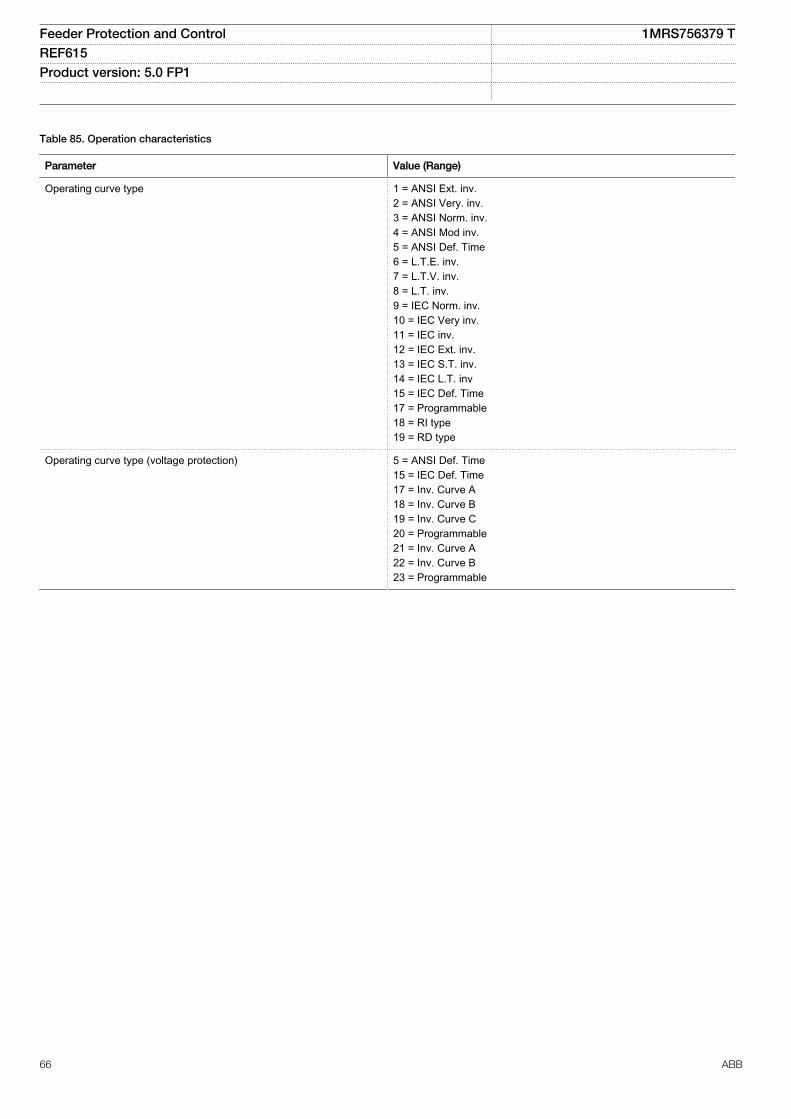
Table 85. Operation characteristics
Parameter Value (Range)
Operating curve type 1 = ANSI Ext. inv.2 = ANSI Very. inv.3 = ANSI Norm. inv.4 = ANSI Mod inv.5 = ANSI Def. Time6 = L.T.E. inv.7 = L.T.V. inv.8 = L.T. inv.9 = IEC Norm. inv.10 = IEC Very inv.11 = IEC inv.12 = IEC Ext. inv.13 = IEC S.T. inv.14 = IEC L.T. inv15 = IEC Def. Time17 = Programmable18 = RI type19 = RD type
Operating curve type (voltage protection) 5 = ANSI Def. Time15 = IEC Def. Time17 = Inv. Curve A18 = Inv. Curve B19 = Inv. Curve C20 = Programmable21 = Inv. Curve A22 = Inv. Curve B23 = Programmable
Feeder Protection and Control 1MRS756379 TREF615 Product version: 5.0 FP1
66 ABB
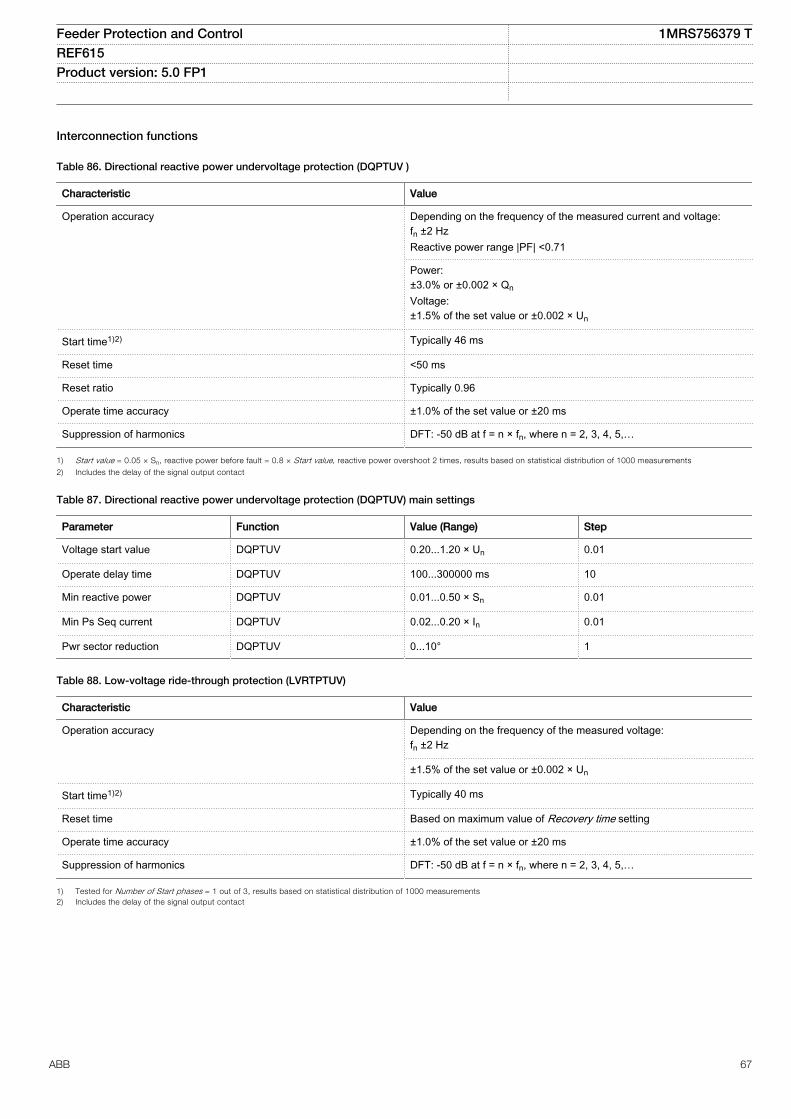
Interconnection functions
Table 86. Directional reactive power undervoltage protection (DQPTUV )
Characteristic Value
Operation accuracy Depending on the frequency of the measured current and voltage:fn ±2 HzReactive power range |PF| <0.71
Power:±3.0% or ±0.002 × QnVoltage:±1.5% of the set value or ±0.002 × Un
Start time1)2) Typically 46 ms
Reset time <50 ms
Reset ratio Typically 0.96
Operate time accuracy ±1.0% of the set value or ±20 ms
Suppression of harmonics DFT: -50 dB at f = n × fn, where n = 2, 3, 4, 5,…
1) Start value = 0.05 × Sn, reactive power before fault = 0.8 × Start value, reactive power overshoot 2 times, results based on statistical distribution of 1000 measurements
2) Includes the delay of the signal output contact
Table 87. Directional reactive power undervoltage protection (DQPTUV) main settings
Parameter Function Value (Range) Step
Voltage start value DQPTUV 0.20...1.20 × Un 0.01
Operate delay time DQPTUV 100...300000 ms 10
Min reactive power DQPTUV 0.01...0.50 × Sn 0.01
Min Ps Seq current DQPTUV 0.02...0.20 × In 0.01
Pwr sector reduction DQPTUV 0...10° 1
Table 88. Low-voltage ride-through protection (LVRTPTUV)
Characteristic Value
Operation accuracy Depending on the frequency of the measured voltage:fn ±2 Hz
±1.5% of the set value or ±0.002 × Un
Start time1)2) Typically 40 ms
Reset time Based on maximum value of Recovery time setting
Operate time accuracy ±1.0% of the set value or ±20 ms
Suppression of harmonics DFT: -50 dB at f = n × fn, where n = 2, 3, 4, 5,…
1) Tested for Number of Start phases = 1 out of 3, results based on statistical distribution of 1000 measurements2) Includes the delay of the signal output contact
Feeder Protection and Control 1MRS756379 TREF615 Product version: 5.0 FP1
ABB 67
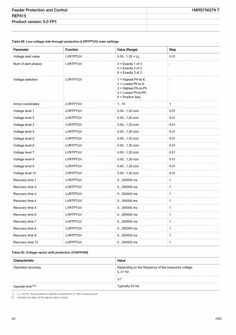
Table 89. Low-voltage ride-through protection (LVRTPTUV) main settings
Parameter Function Value (Range) Step
Voltage start value LVRTPTUV 0.05...1.20 × Un 0.01
Num of start phases LVRTPTUV 4 = Exactly 1 of 35 = Exactly 2 of 36 = Exactly 3 of 3
-
Voltage selection LVRTPTUV 1 = Highest Ph-to-E2 = Lowest Ph-to-E3 = Highest Ph-to-Ph4 = Lowest Ph-to-Ph5 = Positive Seq
-
Active coordinates LVRTPTUV 1...10 1
Voltage level 1 LVRTPTUV 0.00...1.20 xUn 0.01
Voltage level 2 LVRTPTUV 0.00...1.20 xUn 0.01
Voltage level 3 LVRTPTUV 0.00...1.20 xUn 0.01
Voltage level 4 LVRTPTUV 0.00...1.20 xUn 0.01
Voltage level 5 LVRTPTUV 0.00...1.20 xUn 0.01
Voltage level 6 LVRTPTUV 0.00...1.20 xUn 0.01
Voltage level 7 LVRTPTUV 0.00...1.20 xUn 0.01
Voltage level 8 LVRTPTUV 0.00...1.20 xUn 0.01
Voltage level 9 LVRTPTUV 0.00...1.20 xUn 0.01
Voltage level 10 LVRTPTUV 0.00...1.20 xUn 0.01
Recovery time 1 LVRTPTUV 0...300000 ms 1
Recovery time 2 LVRTPTUV 0...300000 ms 1
Recovery time 3 LVRTPTUV 0...300000 ms 1
Recovery time 4 LVRTPTUV 0...300000 ms 1
Recovery time 5 LVRTPTUV 0...300000 ms 1
Recovery time 6 LVRTPTUV 0...300000 ms 1
Recovery time 7 LVRTPTUV 0...300000 ms 1
Recovery time 8 LVRTPTUV 0...300000 ms 1
Recovery time 9 LVRTPTUV 0...300000 ms 1
Recovery time 10 LVRTPTUV 0...300000 ms 1
Table 90. Voltage vector shift protection (VVSPPAM)
Characteristic Value
Operation accuracy Depending on the frequency of the measured voltage:fn ±1 Hz
±1°
Operate time1)2) Typically 53 ms
1) fn = 50 Hz, results based on statistical distribution of 1000 measurements
2) Includes the delay of the signal output contact
Feeder Protection and Control 1MRS756379 TREF615 Product version: 5.0 FP1
68 ABB

Table 91. Voltage vector shift protection (VVSPPAM) main settings
Parameter Function Value (Range) Step
Start value VVSPPAM 2.0...30.0° 0.1
Over Volt Blk value VVSPPAM 0.40...1.50 × Un 0.01
Under Volt Blk value VVSPPAM 0.15...1.00 × Un 0.01
Phase supervision VVSPPAM 7 = Ph A + B + C8 = Pos sequence
-
Feeder Protection and Control 1MRS756379 TREF615 Product version: 5.0 FP1
ABB 69
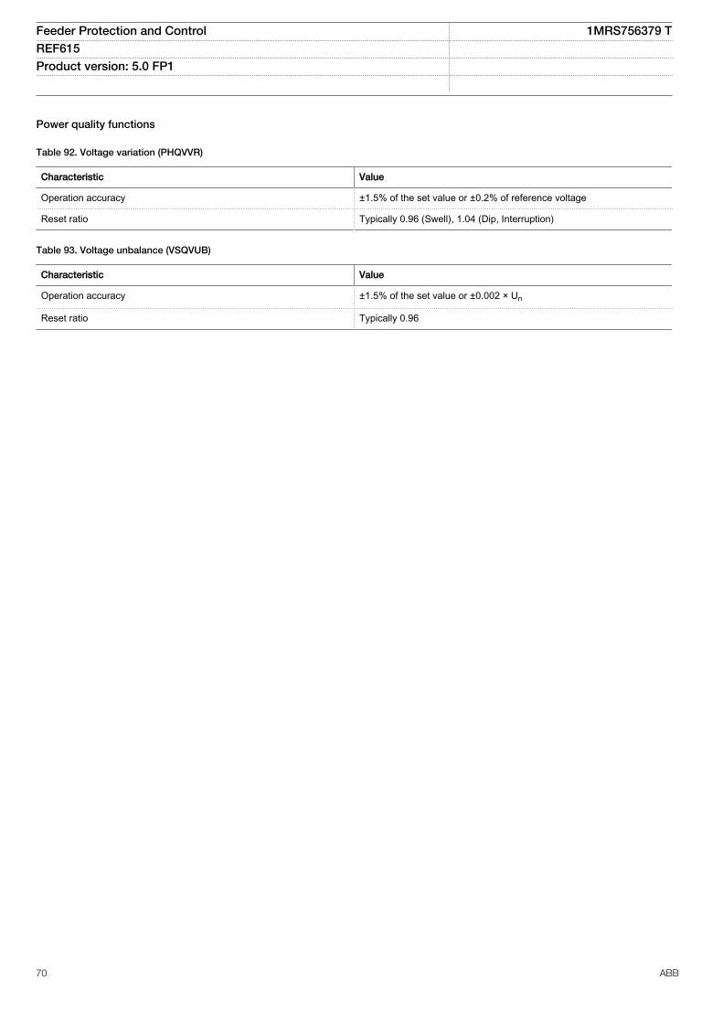
Power quality functions
Table 92. Voltage variation (PHQVVR)
Characteristic Value
Operation accuracy ±1.5% of the set value or ±0.2% of reference voltage
Reset ratio Typically 0.96 (Swell), 1.04 (Dip, Interruption)
Table 93. Voltage unbalance (VSQVUB)
Characteristic Value
Operation accuracy ±1.5% of the set value or ±0.002 × Un
Reset ratio Typically 0.96
Feeder Protection and Control 1MRS756379 TREF615 Product version: 5.0 FP1
70 ABB
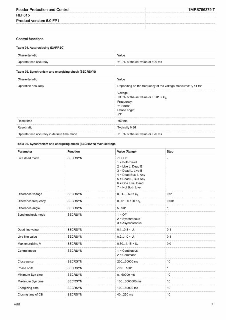
Control functions
Table 94. Autoreclosing (DARREC)
Characteristic Value
Operate time accuracy ±1.0% of the set value or ±20 ms
Table 95. Synchronism and energizing check (SECRSYN)
Characteristic Value
Operation accuracy Depending on the frequency of the voltage measured: fn ±1 Hz
Voltage:±3.0% of the set value or ±0.01 × UnFrequency:±10 mHzPhase angle:±3°
Reset time <50 ms
Reset ratio Typically 0.96
Operate time accuracy in definite time mode ±1.0% of the set value or ±20 ms
Table 96. Synchronism and energizing check (SECRSYN) main settings
Parameter Function Value (Range) Step
Live dead mode SECRSYN -1 = Off1 = Both Dead2 = Live L, Dead B3 = Dead L, Live B4 = Dead Bus, L Any5 = Dead L, Bus Any6 = One Live, Dead7 = Not Both Live
-
Difference voltage SECRSYN 0.01...0.50 × Un 0.01
Difference frequency SECRSYN 0.001...0.100 × fn 0.001
Difference angle SECRSYN 5...90° 1
Synchrocheck mode SECRSYN 1 = Off2 = Synchronous3 = Asynchronous
-
Dead line value SECRSYN 0.1...0.8 × Un 0.1
Live line value SECRSYN 0.2...1.0 × Un 0.1
Max energizing V SECRSYN 0.50...1.15 × Un 0.01
Control mode SECRSYN 1 = Continuous2 = Command
-
Close pulse SECRSYN 200...60000 ms 10
Phase shift SECRSYN -180...180° 1
Minimum Syn time SECRSYN 0...60000 ms 10
Maximum Syn time SECRSYN 100...6000000 ms 10
Energizing time SECRSYN 100...60000 ms 10
Closing time of CB SECRSYN 40...250 ms 10
Feeder Protection and Control 1MRS756379 TREF615 Product version: 5.0 FP1
ABB 71
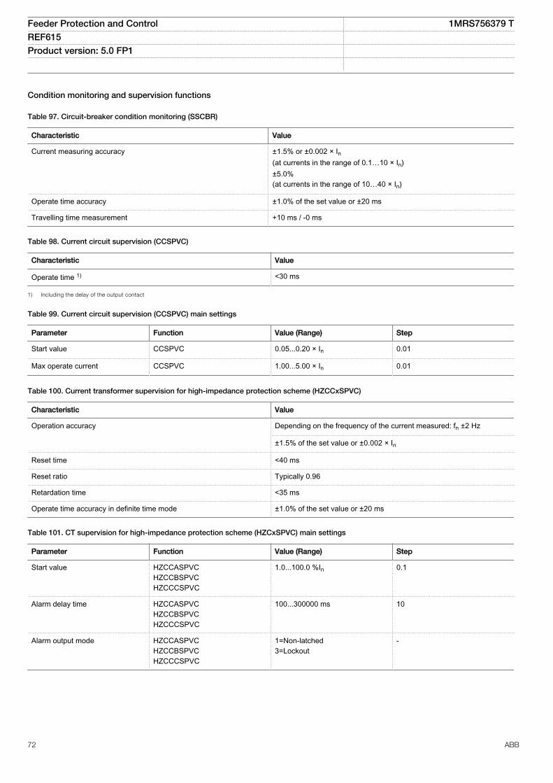
Condition monitoring and supervision functions
Table 97. Circuit-breaker condition monitoring (SSCBR)
Characteristic Value
Current measuring accuracy ±1.5% or ±0.002 × In(at currents in the range of 0.1…10 × In)±5.0%(at currents in the range of 10…40 × In)
Operate time accuracy ±1.0% of the set value or ±20 ms
Travelling time measurement +10 ms / -0 ms
Table 98. Current circuit supervision (CCSPVC)
Characteristic Value
Operate time 1) <30 ms
1) Including the delay of the output contact
Table 99. Current circuit supervision (CCSPVC) main settings
Parameter Function Value (Range) Step
Start value CCSPVC 0.05...0.20 × In 0.01
Max operate current CCSPVC 1.00...5.00 × In 0.01
Table 100. Current transformer supervision for high-impedance protection scheme (HZCCxSPVC)
Characteristic Value
Operation accuracy Depending on the frequency of the current measured: fn ±2 Hz
±1.5% of the set value or ±0.002 × In
Reset time <40 ms
Reset ratio Typically 0.96
Retardation time <35 ms
Operate time accuracy in definite time mode ±1.0% of the set value or ±20 ms
Table 101. CT supervision for high-impedance protection scheme (HZCxSPVC) main settings
Parameter Function Value (Range) Step
Start value HZCCASPVCHZCCBSPVCHZCCCSPVC
1.0...100.0 %In 0.1
Alarm delay time HZCCASPVCHZCCBSPVCHZCCCSPVC
100...300000 ms 10
Alarm output mode HZCCASPVCHZCCBSPVCHZCCCSPVC
1=Non-latched3=Lockout
-
Feeder Protection and Control 1MRS756379 TREF615 Product version: 5.0 FP1
72 ABB
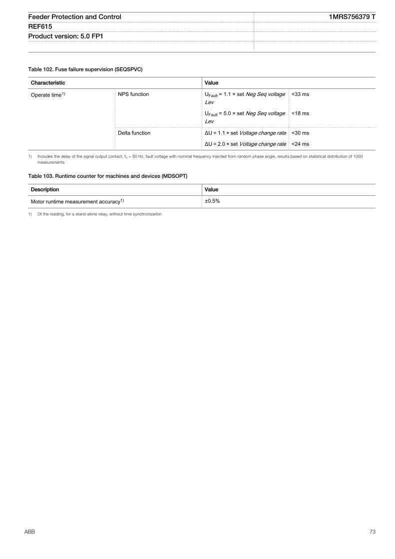
Table 102. Fuse failure supervision (SEQSPVC)
Characteristic Value
Operate time1) NPS function UFault = 1.1 × set Neg Seq voltageLev
<33 ms
UFault = 5.0 × set Neg Seq voltageLev
<18 ms
Delta function ΔU = 1.1 × set Voltage change rate <30 ms
ΔU = 2.0 × set Voltage change rate <24 ms
1) Includes the delay of the signal output contact, fn = 50 Hz, fault voltage with nominal frequency injected from random phase angle, results based on statistical distribution of 1000
measurements
Table 103. Runtime counter for machines and devices (MDSOPT)
Description Value
Motor runtime measurement accuracy1) ±0.5%
1) Of the reading, for a stand-alone relay, without time synchronization
Feeder Protection and Control 1MRS756379 TREF615 Product version: 5.0 FP1
ABB 73
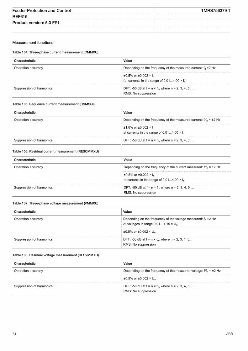
Measurement functions
Table 104. Three-phase current measurement (CMMXU)
Characteristic Value
Operation accuracy Depending on the frequency of the measured current: fn ±2 Hz
±0.5% or ±0.002 × In(at currents in the range of 0.01...4.00 × In)
Suppression of harmonics DFT: -50 dB at f = n × fn, where n = 2, 3, 4, 5,…RMS: No suppression
Table 105. Sequence current measurement (CSMSQI)
Characteristic Value
Operation accuracy Depending on the frequency of the measured current: f/fn = ±2 Hz
±1.0% or ±0.002 × Inat currents in the range of 0.01...4.00 × In
Suppression of harmonics DFT: -50 dB at f = n × fn, where n = 2, 3, 4, 5,…
Table 106. Residual current measurement (RESCMMXU)
Characteristic Value
Operation accuracy Depending on the frequency of the current measured: f/fn = ±2 Hz
±0.5% or ±0.002 × Inat currents in the range of 0.01...4.00 × In
Suppression of harmonics DFT: -50 dB at f = n × fn, where n = 2, 3, 4, 5,…RMS: No suppression
Table 107. Three-phase voltage measurement (VMMXU)
Characteristic Value
Operation accuracy Depending on the frequency of the voltage measured: fn ±2 HzAt voltages in range 0.01…1.15 × Un
±0.5% or ±0.002 × Un
Suppression of harmonics DFT: -50 dB at f = n × fn, where n = 2, 3, 4, 5,…RMS: No suppression
Table 108. Residual voltage measurement (RESVMMXU)
Characteristic Value
Operation accuracy Depending on the frequency of the measured voltage: f/fn = ±2 Hz
±0.5% or ±0.002 × Un
Suppression of harmonics DFT: -50 dB at f = n × fn, where n = 2, 3, 4, 5,…RMS: No suppression
Feeder Protection and Control 1MRS756379 TREF615 Product version: 5.0 FP1
74 ABB
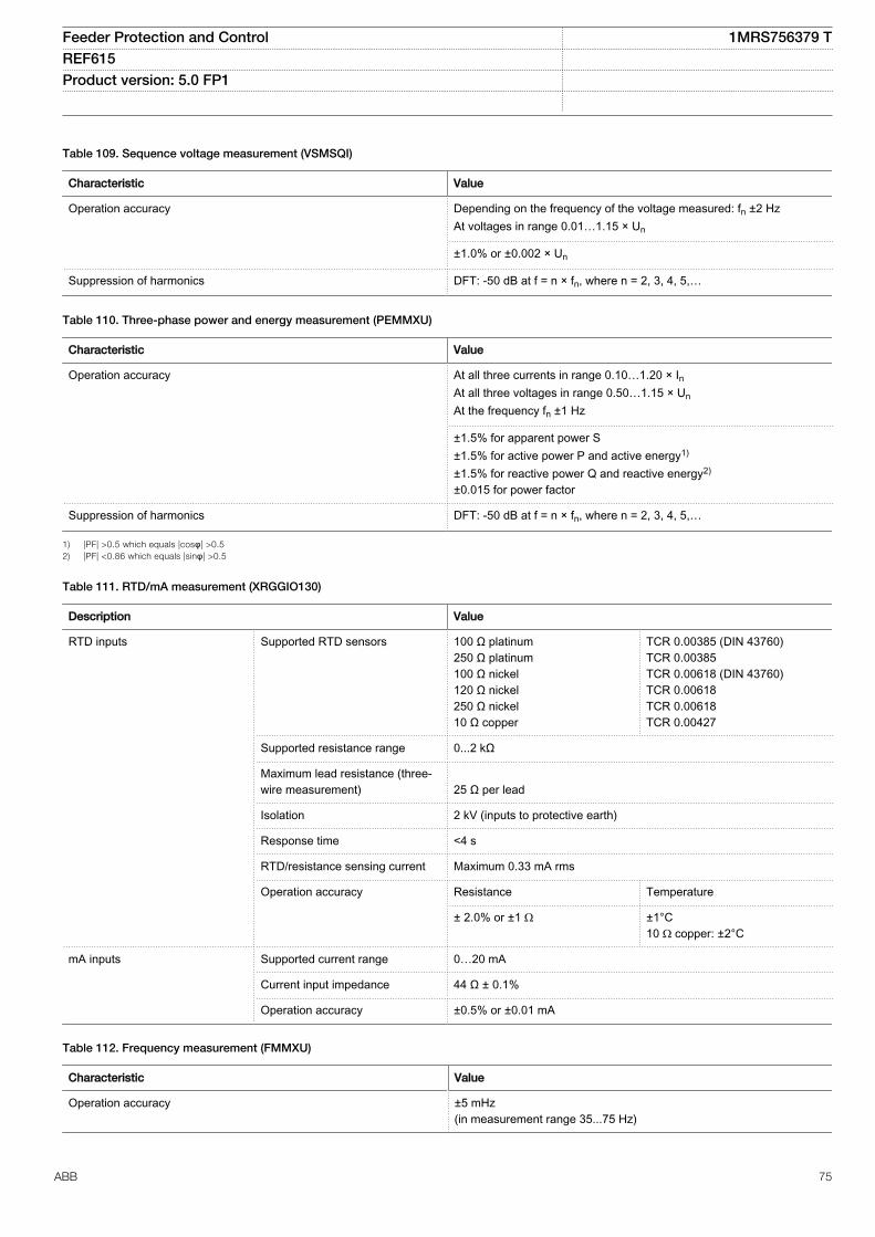
Table 109. Sequence voltage measurement (VSMSQI)
Characteristic Value
Operation accuracy Depending on the frequency of the voltage measured: fn ±2 HzAt voltages in range 0.01…1.15 × Un
±1.0% or ±0.002 × Un
Suppression of harmonics DFT: -50 dB at f = n × fn, where n = 2, 3, 4, 5,…
Table 110. Three-phase power and energy measurement (PEMMXU)
Characteristic Value
Operation accuracy At all three currents in range 0.10…1.20 × InAt all three voltages in range 0.50…1.15 × UnAt the frequency fn ±1 Hz
±1.5% for apparent power S±1.5% for active power P and active energy1)
±1.5% for reactive power Q and reactive energy2)
±0.015 for power factor
Suppression of harmonics DFT: -50 dB at f = n × fn, where n = 2, 3, 4, 5,…
1) |PF| >0.5 which equals |cosφ| >0.52) |PF| <0.86 which equals |sinφ| >0.5
Table 111. RTD/mA measurement (XRGGIO130)
Description Value
RTD inputs Supported RTD sensors 100 Ω platinum250 Ω platinum100 Ω nickel120 Ω nickel250 Ω nickel10 Ω copper
TCR 0.00385 (DIN 43760)TCR 0.00385TCR 0.00618 (DIN 43760)TCR 0.00618TCR 0.00618TCR 0.00427
Supported resistance range 0...2 kΩ
Maximum lead resistance (three-wire measurement) 25 Ω per lead
Isolation 2 kV (inputs to protective earth)
Response time <4 s
RTD/resistance sensing current Maximum 0.33 mA rms
Operation accuracy Resistance Temperature
± 2.0% or ±1 Ω ±1°C10 Ω copper: ±2°C
mA inputs Supported current range 0…20 mA
Current input impedance 44 Ω ± 0.1%
Operation accuracy ±0.5% or ±0.01 mA
Table 112. Frequency measurement (FMMXU)
Characteristic Value
Operation accuracy ±5 mHz(in measurement range 35...75 Hz)
Feeder Protection and Control 1MRS756379 TREF615 Product version: 5.0 FP1
ABB 75
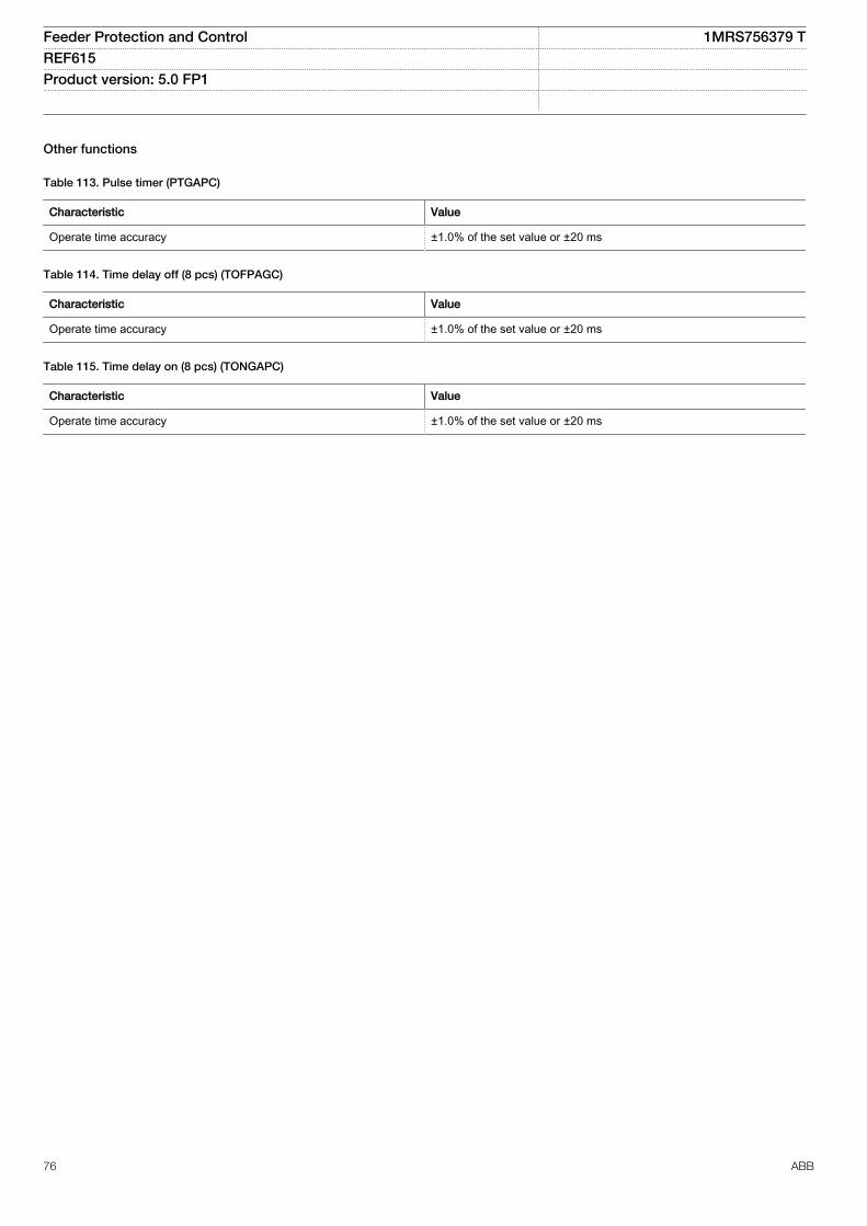
Other functions
Table 113. Pulse timer (PTGAPC)
Characteristic Value
Operate time accuracy ±1.0% of the set value or ±20 ms
Table 114. Time delay off (8 pcs) (TOFPAGC)
Characteristic Value
Operate time accuracy ±1.0% of the set value or ±20 ms
Table 115. Time delay on (8 pcs) (TONGAPC)
Characteristic Value
Operate time accuracy ±1.0% of the set value or ±20 ms
Feeder Protection and Control 1MRS756379 TREF615 Product version: 5.0 FP1
76 ABB
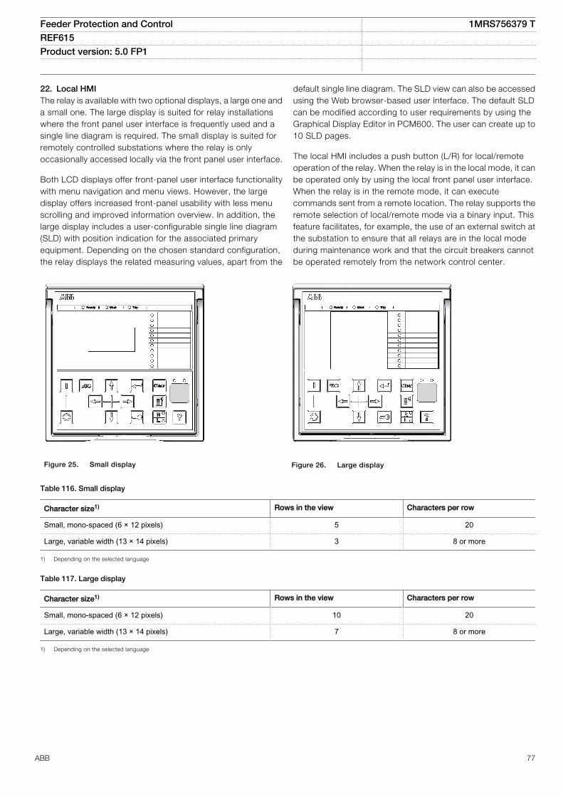
22. Local HMIThe relay is available with two optional displays, a large one anda small one. The large display is suited for relay installationswhere the front panel user interface is frequently used and asingle line diagram is required. The small display is suited forremotely controlled substations where the relay is onlyoccasionally accessed locally via the front panel user interface.
Both LCD displays offer front-panel user interface functionalitywith menu navigation and menu views. However, the largedisplay offers increased front-panel usability with less menuscrolling and improved information overview. In addition, thelarge display includes a user-configurable single line diagram(SLD) with position indication for the associated primaryequipment. Depending on the chosen standard configuration,the relay displays the related measuring values, apart from the
default single line diagram. The SLD view can also be accessedusing the Web browser-based user interface. The default SLDcan be modified according to user requirements by using theGraphical Display Editor in PCM600. The user can create up to10 SLD pages.
The local HMI includes a push button (L/R) for local/remoteoperation of the relay. When the relay is in the local mode, it canbe operated only by using the local front panel user interface.When the relay is in the remote mode, it can executecommands sent from a remote location. The relay supports theremote selection of local/remote mode via a binary input. Thisfeature facilitates, for example, the use of an external switch atthe substation to ensure that all relays are in the local modeduring maintenance work and that the circuit breakers cannotbe operated remotely from the network control center.
IECA070904 V3 EN
Figure 25. Small display
IECA070901 V3 EN
Figure 26. Large display
Table 116. Small display
Character size1) Rows in the view Characters per row
Small, mono-spaced (6 × 12 pixels) 5 20
Large, variable width (13 × 14 pixels) 3 8 or more
1) Depending on the selected language
Table 117. Large display
Character size1) Rows in the view Characters per row
Small, mono-spaced (6 × 12 pixels) 10 20
Large, variable width (13 × 14 pixels) 7 8 or more
1) Depending on the selected language
Feeder Protection and Control 1MRS756379 TREF615 Product version: 5.0 FP1
ABB 77
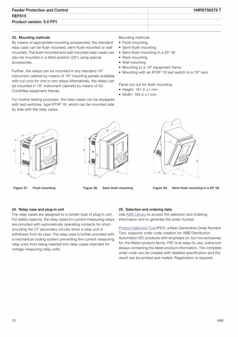
23. Mounting methodsBy means of appropriate mounting accessories, the standardrelay case can be flush mounted, semi-flush mounted or wallmounted. The flush mounted and wall mounted relay cases canalso be mounted in a tilted position (25°) using specialaccessories.
Further, the relays can be mounted in any standard 19”instrument cabinet by means of 19” mounting panels availablewith cut-outs for one or two relays.Alternatively, the relays canbe mounted in 19” instrument cabinets by means of 4UCombiflex equipment frames.
For routine testing purposes, the relay cases can be equippedwith test switches, type RTXP 18, which can be mounted sideby side with the relay cases.
Mounting methods• Flush mounting• Semi-flush mounting• Semi-flush mounting in a 25° tilt• Rack mounting• Wall mounting• Mounting to a 19" equipment frame• Mounting with an RTXP 18 test switch to a 19" rack
Panel cut-out for flush mounting• Height: 161.5 ±1 mm• Width: 165.5 ±1 mm
48
177
160
177
153
164
IECA070900 V4 EN
Figure 27. Flush mounting
98
177
160
186
103
IECA070903 V4 EN
Figure 28. Semi-flush mounting
230
107
25°
133
190
IECA070902 V4 EN
Figure 29. Semi-flush mounting in a 25º tilt
24. Relay case and plug-in unitThe relay cases are assigned to a certain type of plug-in unit.For safety reasons, the relay cases for current measuring relaysare provided with automatically operating contacts for short-circuiting the CT secondary circuits when a relay unit iswithdrawn from its case. The relay case is further provided witha mechanical coding system preventing the current measuringrelay units from being inserted into relay cases intended forvoltage measuring relay units.
25. Selection and ordering dataUse ABB Library to access the selection and orderinginformation and to generate the order number.
Product Selection Tool (PST), a Next-Generation Order NumberTool, supports order code creation for ABB DistributionAutomation IEC products with emphasis on, but not exclusivelyfor, the Relion product family. PST is an easy-to-use, online toolalways containing the latest product information. The completeorder code can be created with detailed specification and theresult can be printed and mailed. Registration is required.
Feeder Protection and Control 1MRS756379 TREF615 Product version: 5.0 FP1
78 ABB
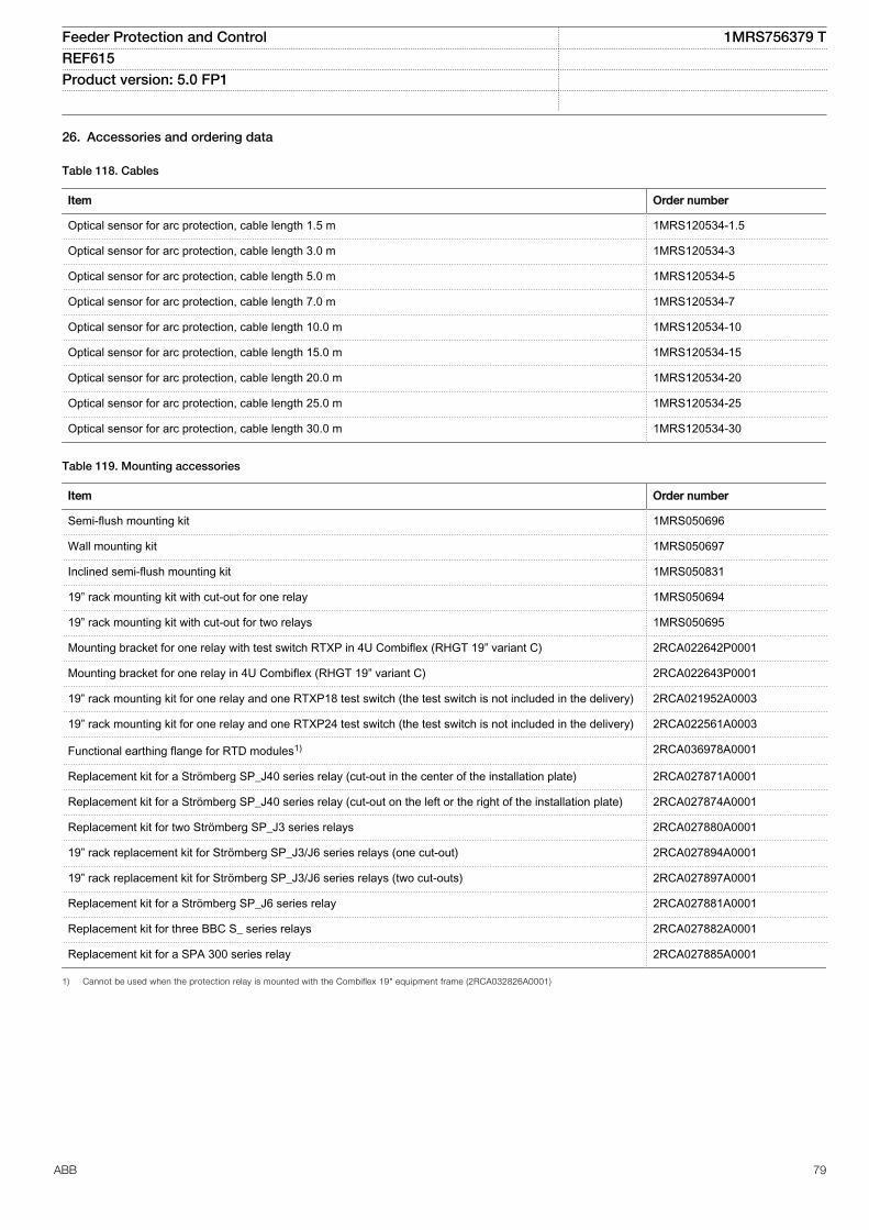
26. Accessories and ordering data
Table 118. Cables
Item Order number
Optical sensor for arc protection, cable length 1.5 m 1MRS120534-1.5
Optical sensor for arc protection, cable length 3.0 m 1MRS120534-3
Optical sensor for arc protection, cable length 5.0 m 1MRS120534-5
Optical sensor for arc protection, cable length 7.0 m 1MRS120534-7
Optical sensor for arc protection, cable length 10.0 m 1MRS120534-10
Optical sensor for arc protection, cable length 15.0 m 1MRS120534-15
Optical sensor for arc protection, cable length 20.0 m 1MRS120534-20
Optical sensor for arc protection, cable length 25.0 m 1MRS120534-25
Optical sensor for arc protection, cable length 30.0 m 1MRS120534-30
Table 119. Mounting accessories
Item Order number
Semi-flush mounting kit 1MRS050696
Wall mounting kit 1MRS050697
Inclined semi-flush mounting kit 1MRS050831
19” rack mounting kit with cut-out for one relay 1MRS050694
19” rack mounting kit with cut-out for two relays 1MRS050695
Mounting bracket for one relay with test switch RTXP in 4U Combiflex (RHGT 19” variant C) 2RCA022642P0001
Mounting bracket for one relay in 4U Combiflex (RHGT 19” variant C) 2RCA022643P0001
19” rack mounting kit for one relay and one RTXP18 test switch (the test switch is not included in the delivery) 2RCA021952A0003
19” rack mounting kit for one relay and one RTXP24 test switch (the test switch is not included in the delivery) 2RCA022561A0003
Functional earthing flange for RTD modules1) 2RCA036978A0001
Replacement kit for a Strömberg SP_J40 series relay (cut-out in the center of the installation plate) 2RCA027871A0001
Replacement kit for a Strömberg SP_J40 series relay (cut-out on the left or the right of the installation plate) 2RCA027874A0001
Replacement kit for two Strömberg SP_J3 series relays 2RCA027880A0001
19” rack replacement kit for Strömberg SP_J3/J6 series relays (one cut-out) 2RCA027894A0001
19” rack replacement kit for Strömberg SP_J3/J6 series relays (two cut-outs) 2RCA027897A0001
Replacement kit for a Strömberg SP_J6 series relay 2RCA027881A0001
Replacement kit for three BBC S_ series relays 2RCA027882A0001
Replacement kit for a SPA 300 series relay 2RCA027885A0001
1) Cannot be used when the protection relay is mounted with the Combiflex 19" equipment frame (2RCA032826A0001)
Feeder Protection and Control 1MRS756379 TREF615 Product version: 5.0 FP1
ABB 79
27. ToolsThe protection relay is delivered as a preconfigured unit. Thedefault parameter setting values can be changed from the front-panel user interface (local HMI), the Web browser-based userinterface (Web HMI) or Protection and Control IED ManagerPCM600 in combination with the relay-specific connectivitypackage.
PCM600 offers extensive relay configuration functions. Forexample, depending on the protection relay, the relay signals,application, graphical display and single-line diagram, and IEC61850 communication, including horizontal GOOSEcommunication, can be modified with PCM600.
When the Web HMI is used, the protection relay can beaccessed either locally or remotely using a Web browser
(Internet Explorer). For security reasons, the Web HMI isdisabled by default but it can be enabled via the local HMI. TheWeb HMI functionality can be limited to read-only access.
The relay connectivity package is a collection of software andspecific relay information, which enables system products andtools to connect and interact with the protection relay. Theconnectivity packages reduce the risk of errors in systemintegration, minimizing device configuration and setup times.Further, the connectivity packages for protection relays of thisproduct series include a flexible update tool for adding oneadditional local HMI language to the protection relay. Theupdate tool is activated using PCM600, and it enables multipleupdates of the additional HMI language, thus offering flexiblemeans for possible future language updates.
Table 120. Tools
Description Version
PCM600 2.6 (Rollup 20150626) or later
Web browser IE 8.0, IE 9.0, IE 10.0 or IE 11.0
REF615 Connectivity Package 5.1 or later
Feeder Protection and Control 1MRS756379 TREF615 Product version: 5.0 FP1
80 ABB
Table 121. Supported functions
Function Web HMI PCM600
Relay parameter setting
Saving of relay parameter settings in the relay
Signal monitoring
Disturbance recorder handling
Alarm LED viewing
Access control management
Relay signal configuration (Signal Matrix) -
Modbus® communication configuration (communication management) -
DNP3 communication configuration (communication management) -
IEC 60870-5-103 communication configuration (communicationmanagement) -
Saving of relay parameter settings in the tool -
Disturbance record analysis -
XRIO parameter export/import
Graphical display configuration -
Application configuration -
IEC 61850 communication configuration, GOOSE (communicationconfiguration) -
Phasor diagram viewing -
Event viewing
Saving of event data on the user's PC
Online monitoring - = Supported
28. Cyber securityThe relay supports role based user authentication andauthorization. It can store 2048 audit trail events to a non-volatile memory. The non-volatile memory is based on amemory type which does not need battery backup or regularcomponent exchange to maintain the memory storage. FTP
and Web HMI use TLS encryption with a minimum of 128 bit keylength protecting the data in transit. In this case the usedcommunication protocols are FTPS and HTTPS. All rearcommunication ports and optional protocol services can bedeactivated according to the required system setup.
Feeder Protection and Control 1MRS756379 TREF615 Product version: 5.0 FP1
ABB 81
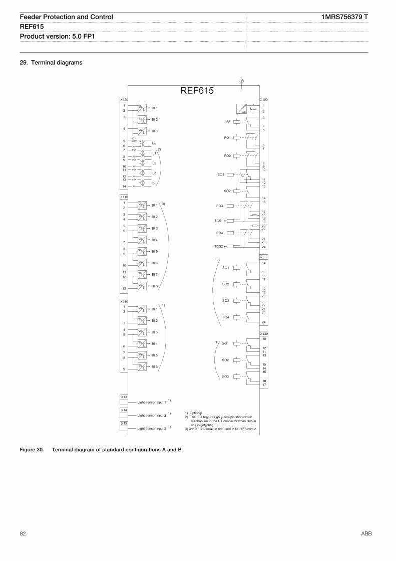
29. Terminal diagrams
IECA070918 V6 EN
Figure 30. Terminal diagram of standard configurations A and B
Feeder Protection and Control 1MRS756379 TREF615 Product version: 5.0 FP1
82 ABB
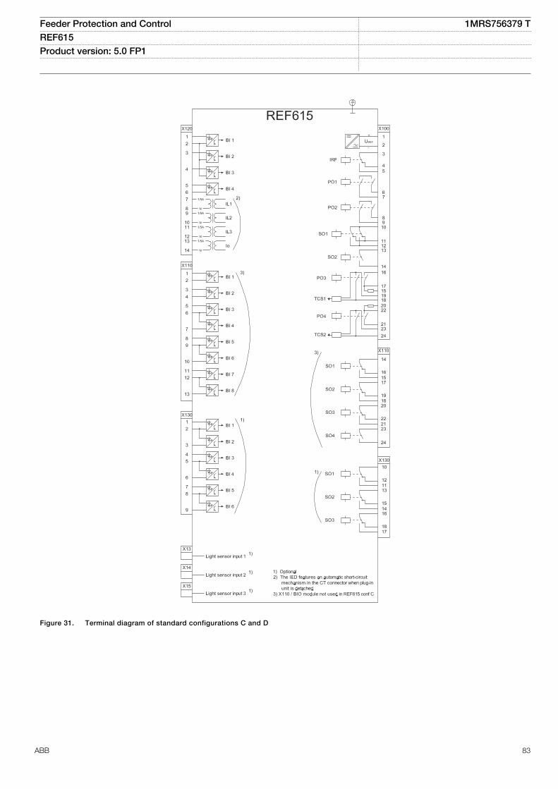
IECA070919 V6 EN
Figure 31. Terminal diagram of standard configurations C and D
Feeder Protection and Control 1MRS756379 TREF615 Product version: 5.0 FP1
ABB 83
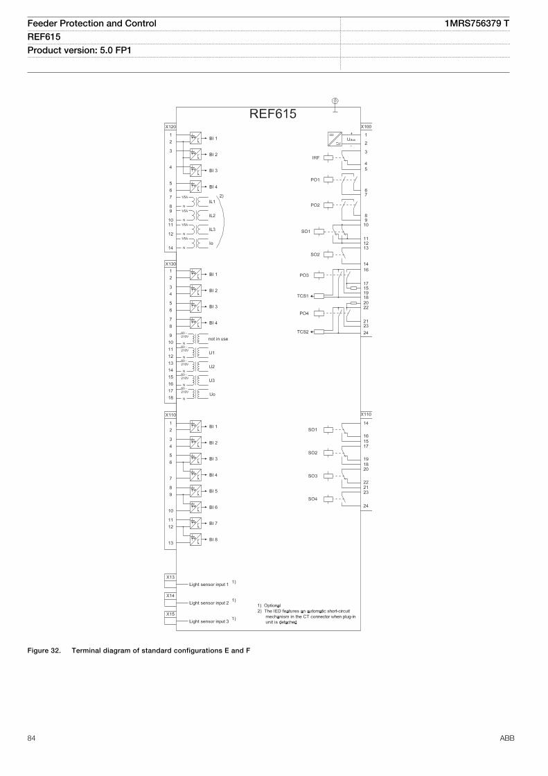
GUID-FA7A5888-5288-4969-84D0-00354EAB3997 V4 EN
Figure 32. Terminal diagram of standard configurations E and F
Feeder Protection and Control 1MRS756379 TREF615 Product version: 5.0 FP1
84 ABB
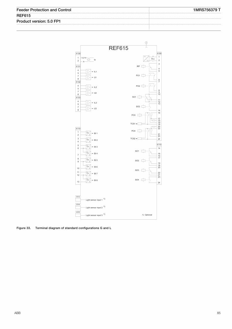
GUID-88778A7A-2A9B-46BF-AC33-075626A03AC8 V1 EN
Figure 33. Terminal diagram of standard configurations G and L
Feeder Protection and Control 1MRS756379 TREF615 Product version: 5.0 FP1
ABB 85
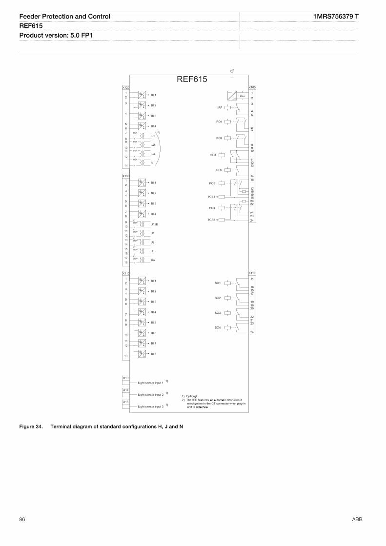
GUID-F4CCBBC7-41DD-4E1C-99E8-69029EC6933C V1 EN
Figure 34. Terminal diagram of standard configurations H, J and N
Feeder Protection and Control 1MRS756379 TREF615 Product version: 5.0 FP1
86 ABB
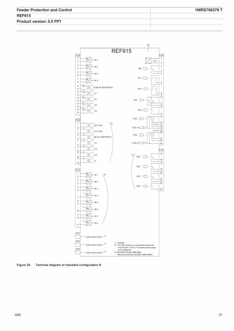
REF615
X13Light sensor input 1 1)
X14Light sensor input 2 1)
X15Light sensor input 3 1)
1) Optional2) The IED features an automatic short-circuit mechanism in the CT connector when plug-in unit is detached3) BIO0005 Module (8BI+4BO) Alternative Module BIO0007 (8BI+3HSO)
16
17
1918
X100
67
89
10
111213
15
14
2
1
3
45
22
212324
SO2
TCS2
PO4
SO1
TCS1
PO3
PO2
PO1
IRF
+
-Uaux
20
X110
34
56
7
89
10BI 6
BI 5
BI 4
BI 3
BI 2
BI 8
BI 712
13
11
BI 112
X110
16
14
15
19
17
18
22
20
21
SO3
SO2
SO1
23SO4
24
2)
X120
1
23
45
67
89
1011
1213
14
not in use1/5A
N
not in use
IoB (for HREFPDIF1)
IL1
IL2
IL3
Io
1/5A
N1/5A
N1/5A
N1/5A
N1/5A
N1/5A
N
X13012
34
56
BI 4
BI 3
BI 2
BI 1
87
9101112
U12B (for SECRSYN1)
1314
U1
1516
U2
1718
U3
UoN
N
N
N
60 -
N
210V
60 -210V
60 -210V
60 -210V
60 -210V
3)
3)
GUID-A45849DB-919C-40DF-9B12-046614708F09 V1 EN
Figure 35. Terminal diagram of standard configuration K
Feeder Protection and Control 1MRS756379 TREF615 Product version: 5.0 FP1
ABB 87

30. CertificatesDNV GL has issued an IEC 61850 Edition 2 Certificate Level A1
for Relion® 615 series. Certificate number: 7410570I-OPE/INC15-1136.
DNV GL has issued an IEC 61850 Edition 1 Certificate Level A1
for Relion® 615 series. Certificate number: 74105701-OPE/INC15-1145.
Additional certificates can be found on the product page.
31. Inspection reportsKEMA has issued an Inspection report for REF615,“Comparison between hardwired and GOOSE performance ofUniGear switchgear panels with REF615 and REF630 FeederProtection and Control IEDs based on IEC 62271-3”. Reportnumber: 70972064-TDT 09-1398.
The Inspection report concludes in its summary, apart from theperformance comparisons, that “both the REF630 and REF615comply to the performance class P1 message type 1A “Trip” fordistribution bays (transfer time <10 msec) as defined in IEC61850-5”.
32. ReferencesThe www.abb.com/substationautomation portal providesinformation on the entire range of distribution automationproducts and services.
The latest relevant information on the REF615 protection andcontrol relay is found on the product page. Scroll down thepage to find and download the related documentation.
Feeder Protection and Control 1MRS756379 TREF615 Product version: 5.0 FP1
88 ABB
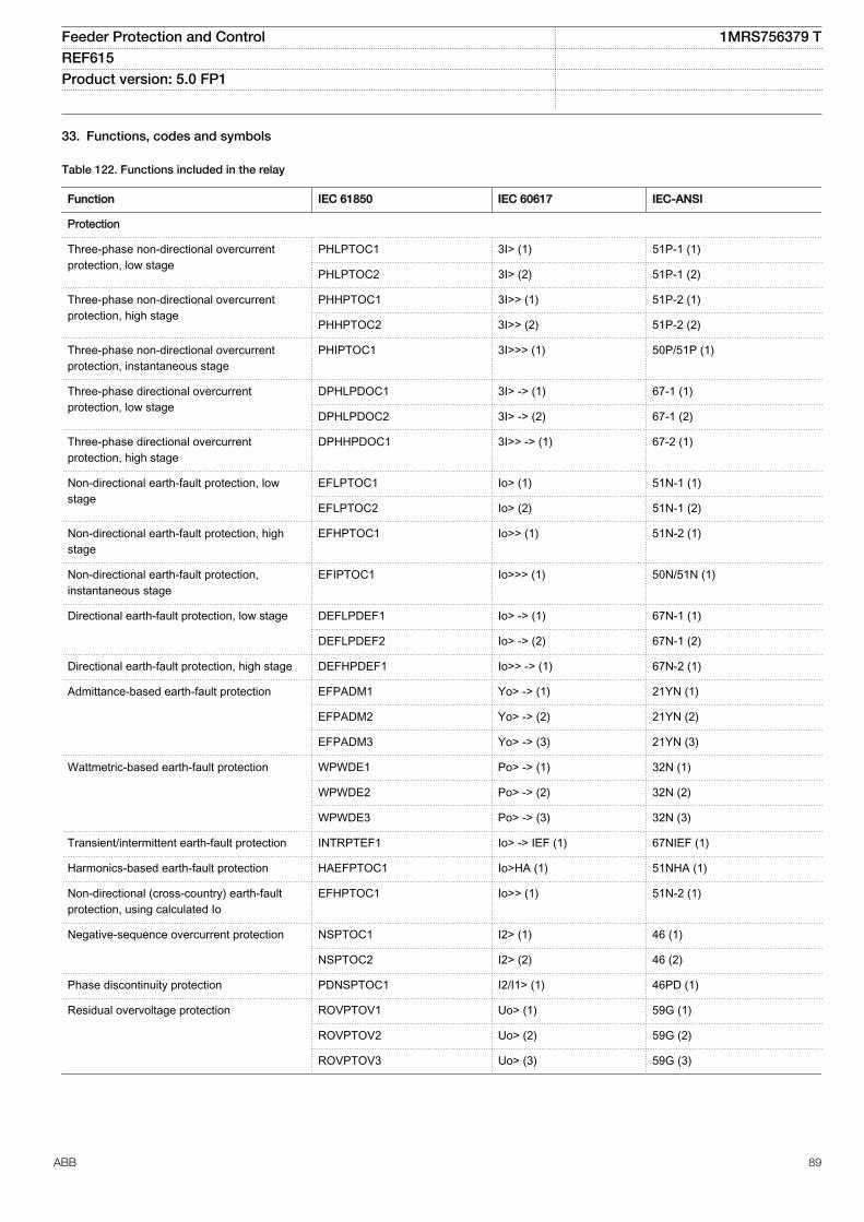
33. Functions, codes and symbols
Table 122. Functions included in the relay
Function IEC 61850 IEC 60617 IEC-ANSI
Protection
Three-phase non-directional overcurrentprotection, low stage
PHLPTOC1 3I> (1) 51P-1 (1)
PHLPTOC2 3I> (2) 51P-1 (2)
Three-phase non-directional overcurrentprotection, high stage
PHHPTOC1 3I>> (1) 51P-2 (1)
PHHPTOC2 3I>> (2) 51P-2 (2)
Three-phase non-directional overcurrentprotection, instantaneous stage
PHIPTOC1 3I>>> (1) 50P/51P (1)
Three-phase directional overcurrentprotection, low stage
DPHLPDOC1 3I> -> (1) 67-1 (1)
DPHLPDOC2 3I> -> (2) 67-1 (2)
Three-phase directional overcurrentprotection, high stage
DPHHPDOC1 3I>> -> (1) 67-2 (1)
Non-directional earth-fault protection, lowstage
EFLPTOC1 Io> (1) 51N-1 (1)
EFLPTOC2 Io> (2) 51N-1 (2)
Non-directional earth-fault protection, highstage
EFHPTOC1 Io>> (1) 51N-2 (1)
Non-directional earth-fault protection,instantaneous stage
EFIPTOC1 Io>>> (1) 50N/51N (1)
Directional earth-fault protection, low stage DEFLPDEF1 Io> -> (1) 67N-1 (1)
DEFLPDEF2 Io> -> (2) 67N-1 (2)
Directional earth-fault protection, high stage DEFHPDEF1 Io>> -> (1) 67N-2 (1)
Admittance-based earth-fault protection EFPADM1 Yo> -> (1) 21YN (1)
EFPADM2 Yo> -> (2) 21YN (2)
EFPADM3 Yo> -> (3) 21YN (3)
Wattmetric-based earth-fault protection WPWDE1 Po> -> (1) 32N (1)
WPWDE2 Po> -> (2) 32N (2)
WPWDE3 Po> -> (3) 32N (3)
Transient/intermittent earth-fault protection INTRPTEF1 Io> -> IEF (1) 67NIEF (1)
Harmonics-based earth-fault protection HAEFPTOC1 Io>HA (1) 51NHA (1)
Non-directional (cross-country) earth-faultprotection, using calculated Io
EFHPTOC1 Io>> (1) 51N-2 (1)
Negative-sequence overcurrent protection NSPTOC1 I2> (1) 46 (1)
NSPTOC2 I2> (2) 46 (2)
Phase discontinuity protection PDNSPTOC1 I2/I1> (1) 46PD (1)
Residual overvoltage protection ROVPTOV1 Uo> (1) 59G (1)
ROVPTOV2 Uo> (2) 59G (2)
ROVPTOV3 Uo> (3) 59G (3)
Feeder Protection and Control 1MRS756379 TREF615 Product version: 5.0 FP1
ABB 89
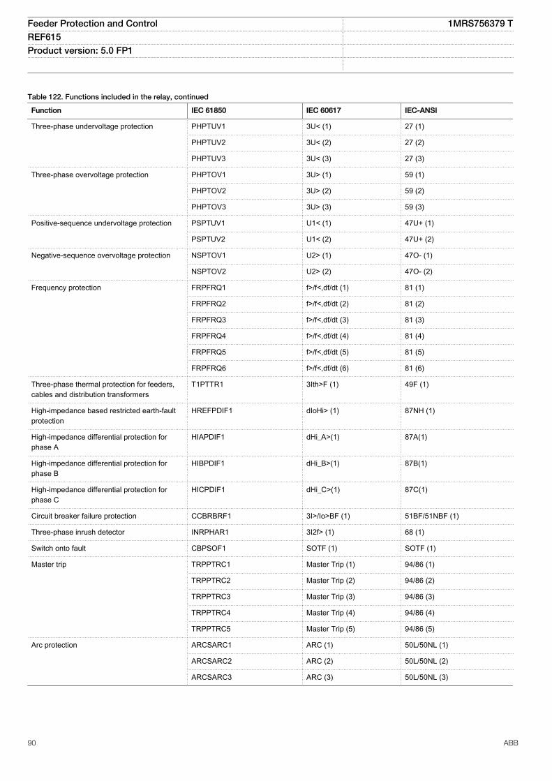
Table 122. Functions included in the relay, continued
Function IEC 61850 IEC 60617 IEC-ANSI
Three-phase undervoltage protection PHPTUV1 3U< (1) 27 (1)
PHPTUV2 3U< (2) 27 (2)
PHPTUV3 3U< (3) 27 (3)
Three-phase overvoltage protection PHPTOV1 3U> (1) 59 (1)
PHPTOV2 3U> (2) 59 (2)
PHPTOV3 3U> (3) 59 (3)
Positive-sequence undervoltage protection PSPTUV1 U1< (1) 47U+ (1)
PSPTUV2 U1< (2) 47U+ (2)
Negative-sequence overvoltage protection NSPTOV1 U2> (1) 47O- (1)
NSPTOV2 U2> (2) 47O- (2)
Frequency protection FRPFRQ1 f>/f<,df/dt (1) 81 (1)
FRPFRQ2 f>/f<,df/dt (2) 81 (2)
FRPFRQ3 f>/f<,df/dt (3) 81 (3)
FRPFRQ4 f>/f<,df/dt (4) 81 (4)
FRPFRQ5 f>/f<,df/dt (5) 81 (5)
FRPFRQ6 f>/f<,df/dt (6) 81 (6)
Three-phase thermal protection for feeders,cables and distribution transformers
T1PTTR1 3Ith>F (1) 49F (1)
High-impedance based restricted earth-faultprotection
HREFPDIF1 dIoHi> (1) 87NH (1)
High-impedance differential protection forphase A
HIAPDIF1 dHi_A>(1) 87A(1)
High-impedance differential protection forphase B
HIBPDIF1 dHi_B>(1) 87B(1)
High-impedance differential protection forphase C
HICPDIF1 dHi_C>(1) 87C(1)
Circuit breaker failure protection CCBRBRF1 3I>/Io>BF (1) 51BF/51NBF (1)
Three-phase inrush detector INRPHAR1 3I2f> (1) 68 (1)
Switch onto fault CBPSOF1 SOTF (1) SOTF (1)
Master trip TRPPTRC1 Master Trip (1) 94/86 (1)
TRPPTRC2 Master Trip (2) 94/86 (2)
TRPPTRC3 Master Trip (3) 94/86 (3)
TRPPTRC4 Master Trip (4) 94/86 (4)
TRPPTRC5 Master Trip (5) 94/86 (5)
Arc protection ARCSARC1 ARC (1) 50L/50NL (1)
ARCSARC2 ARC (2) 50L/50NL (2)
ARCSARC3 ARC (3) 50L/50NL (3)
Feeder Protection and Control 1MRS756379 TREF615 Product version: 5.0 FP1
90 ABB
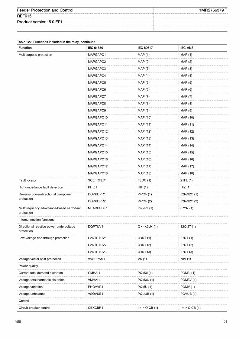
Table 122. Functions included in the relay, continued
Function IEC 61850 IEC 60617 IEC-ANSI
Multipurpose protection MAPGAPC1 MAP (1) MAP (1)
MAPGAPC2 MAP (2) MAP (2)
MAPGAPC3 MAP (3) MAP (3)
MAPGAPC4 MAP (4) MAP (4)
MAPGAPC5 MAP (5) MAP (5)
MAPGAPC6 MAP (6) MAP (6)
MAPGAPC7 MAP (7) MAP (7)
MAPGAPC8 MAP (8) MAP (8)
MAPGAPC9 MAP (9) MAP (9)
MAPGAPC10 MAP (10) MAP (10)
MAPGAPC11 MAP (11) MAP (11)
MAPGAPC12 MAP (12) MAP (12)
MAPGAPC13 MAP (13) MAP (13)
MAPGAPC14 MAP (14) MAP (14)
MAPGAPC15 MAP (15) MAP (15)
MAPGAPC16 MAP (16) MAP (16)
MAPGAPC17 MAP (17) MAP (17)
MAPGAPC18 MAP (18) MAP (18)
Fault locator SCEFRFLO1 FLOC (1) 21FL (1)
High-impedance fault detection PHIZ1 HIF (1) HIZ (1)
Reverse power/directional overpowerprotection
DOPPDPR1 P>/Q> (1) 32R/32O (1)
DOPPDPR2 P>/Q> (2) 32R/32O (2)
Multifrequency admittance-based earth-faultprotection
MFADPSDE1 Io> ->Y (1) 67YN (1)
Interconnection functions
Directional reactive power undervoltageprotection
DQPTUV1 Q> ->,3U< (1) 32Q,27 (1)
Low-voltage ride-through protection LVRTPTUV1 U<RT (1) 27RT (1)
LVRTPTUV2 U<RT (2) 27RT (2)
LVRTPTUV3 U<RT (3) 27RT (3)
Voltage vector shift protection VVSPPAM1 VS (1) 78V (1)
Power quality
Current total demand distortion CMHAI1 PQM3I (1) PQM3I (1)
Voltage total harmonic distortion VMHAI1 PQM3U (1) PQM3V (1)
Voltage variation PHQVVR1 PQMU (1) PQMV (1)
Voltage unbalance VSQVUB1 PQUUB (1) PQVUB (1)
Control
Circuit-breaker control CBXCBR1 I <-> O CB (1) I <-> O CB (1)
Feeder Protection and Control 1MRS756379 TREF615 Product version: 5.0 FP1
ABB 91
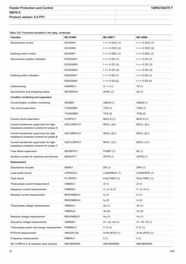
Table 122. Functions included in the relay, continued
Function IEC 61850 IEC 60617 IEC-ANSI
Disconnector control DCXSWI1 I <-> O DCC (1) I <-> O DCC (1)
DCXSWI2 I <-> O DCC (2) I <-> O DCC (2)
Earthing switch control ESXSWI1 I <-> O ESC (1) I <-> O ESC (1)
Disconnector position indication DCSXSWI1 I <-> O DC (1) I <-> O DC (1)
DCSXSWI2 I <-> O DC (2) I <-> O DC (2)
DCSXSWI3 I <-> O DC (3) I <-> O DC (3)
Earthing switch indication ESSXSWI1 I <-> O ES (1) I <-> O ES (1)
ESSXSWI2 I <-> O ES (2) I <-> O ES (2)
Autoreclosing DARREC1 O -> I (1) 79 (1)
Synchronism and energizing check SECRSYN1 SYNC (1) 25 (1)
Condition monitoring and supervision
Circuit-breaker condition monitoring SSCBR1 CBCM (1) CBCM (1)
Trip circuit supervision TCSSCBR1 TCS (1) TCM (1)
TCSSCBR2 TCS (2) TCM (2)
Current circuit supervision CCSPVC1 MCS 3I (1) MCS 3I (1)
Current transformer supervision for high-impedance protection scheme for phase A
HZCCASPVC1 MCS I_A(1) MCS I_A(1)
Current transformer supervision for high-impedance protection scheme for phase B
HZCCBSPVC1 MCS I_B(1) MCS I_B(1)
Current transformer supervision for high-impedance protection scheme for phase C
HZCCCSPVC1 MCS I_C(1) MCS I_C(1)
Fuse failure supervision SEQSPVC1 FUSEF (1) 60 (1)
Runtime counter for machines and devices MDSOPT1 OPTS (1) OPTM (1)
Measurement
Disturbance recorder RDRE1 DR (1) DFR (1)
Load profile record LDPRLRC1 LOADPROF (1) LOADPROF (1)
Fault record FLTRFRC1 FAULTREC (1) FAULTREC (1)
Three-phase current measurement CMMXU1 3I (1) 3I (1)
Sequence current measurement CSMSQI1 I1, I2, I0 (1) I1, I2, I0 (1)
Residual current measurement RESCMMXU1 Io (1) In (1)
RESCMMXU2 Io (2) In (2)
Three-phase voltage measurement VMMXU1 3U (1) 3V (1)
VMMXU2 3U (2) 3V (2)
Residual voltage measurement RESVMMXU1 Uo (1) Vn (1)
Sequence voltage measurement VSMSQI1 U1, U2, U0 (1) V1, V2, V0 (1)
Three-phase power and energy measurement PEMMXU1 P, E (1) P, E (1)
RTD/mA measurement XRGGIO130 X130 (RTD) (1) X130 (RTD) (1)
Frequency measurement FMMXU1 f (1) f (1)
IEC 61850-9-2 LE sampled value sending SMVSENDER SMVSENDER SMVSENDER
Feeder Protection and Control 1MRS756379 TREF615 Product version: 5.0 FP1
92 ABB
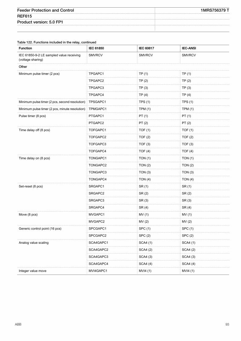
Table 122. Functions included in the relay, continued
Function IEC 61850 IEC 60617 IEC-ANSI
IEC 61850-9-2 LE sampled value receiving(voltage sharing)
SMVRCV SMVRCV SMVRCV
Other
Minimum pulse timer (2 pcs) TPGAPC1 TP (1) TP (1)
TPGAPC2 TP (2) TP (2)
TPGAPC3 TP (3) TP (3)
TPGAPC4 TP (4) TP (4)
Minimum pulse timer (2 pcs, second resolution) TPSGAPC1 TPS (1) TPS (1)
Minimum pulse timer (2 pcs, minute resolution) TPMGAPC1 TPM (1) TPM (1)
Pulse timer (8 pcs) PTGAPC1 PT (1) PT (1)
PTGAPC2 PT (2) PT (2)
Time delay off (8 pcs) TOFGAPC1 TOF (1) TOF (1)
TOFGAPC2 TOF (2) TOF (2)
TOFGAPC3 TOF (3) TOF (3)
TOFGAPC4 TOF (4) TOF (4)
Time delay on (8 pcs) TONGAPC1 TON (1) TON (1)
TONGAPC2 TON (2) TON (2)
TONGAPC3 TON (3) TON (3)
TONGAPC4 TON (4) TON (4)
Set-reset (8 pcs) SRGAPC1 SR (1) SR (1)
SRGAPC2 SR (2) SR (2)
SRGAPC3 SR (3) SR (3)
SRGAPC4 SR (4) SR (4)
Move (8 pcs) MVGAPC1 MV (1) MV (1)
MVGAPC2 MV (2) MV (2)
Generic control point (16 pcs) SPCGAPC1 SPC (1) SPC (1)
SPCGAPC2 SPC (2) SPC (2)
Analog value scaling SCA4GAPC1 SCA4 (1) SCA4 (1)
SCA4GAPC2 SCA4 (2) SCA4 (2)
SCA4GAPC3 SCA4 (3) SCA4 (3)
SCA4GAPC4 SCA4 (4) SCA4 (4)
Integer value move MVI4GAPC1 MVI4 (1) MVI4 (1)
Feeder Protection and Control 1MRS756379 TREF615 Product version: 5.0 FP1
ABB 93
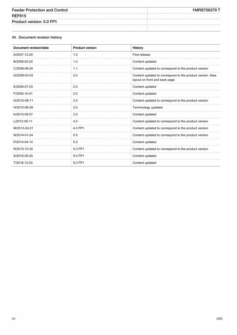
34. Document revision history
Document revision/date Product version History
A/2007-12-20 1.0 First release
B/2008-02-22 1.0 Content updated
C/2008-06-20 1.1 Content updated to correspond to the product version
D/2009-03-03 2.0 Content updated to correspond to the product version. Newlayout on front and back page
E/2009-07-03 2.0 Content updated
F/2009-10-01 2.0 Content updated
G/2010-06-11 3.0 Content updated to correspond to the product version
H/2010-06-29 3.0 Terminology updated
K/2010-09-07 3.0 Content updated
L/2012-05-11 4.0 Content updated to correspond to the product version
M/2013-02-21 4.0 FP1 Content updated to correspond to the product version
N/2014-01-24 5.0 Content updated to correspond to the product version
P/2014-04-10 5.0 Content updated
R/2015-10-30 5.0 FP1 Content updated to correspond to the product version
S/2016-05-20 5.0 FP1 Content updated
T/2018-12-20 5.0 FP1 Content updated
Feeder Protection and Control 1MRS756379 TREF615 Product version: 5.0 FP1
94 ABB

95
ABB Distribution SolutionsDistribution AutomationP.O. Box 699FI-65101 VAASA, FinlandPhone +358 10 22 11
ABB Distribution AutomationManeja WorksVadodara-390013, IndiaPhone +91 265 2604386Fax +91 265 2638922
www.abb.com/mediumvoltagewww.abb.com/relionwww.abb.com/substationautomation
—
© Copyright 2018 ABB. All rights reserved. 1MR
S75
6379
T