
PRODUCT GUIDE - · PDF filefrom our first Product Guide we have ... frequency protections and...
34
PRODUCT GUIDE Electronic edition – Applications CREATIVE ENGINEERING
Transcript of PRODUCT GUIDE - · PDF filefrom our first Product Guide we have ... frequency protections and...

PRODUCT GUIDEElectronic edition – Applications
CrEAtivE EnginEEring

The interactive simulator provides a taste of the new InteliVision, with demo and preview options illustrating screen information and function.
simulator
OnlInE

InteliVision is a new generation colour display unit for either InteliGenNT / InteliSysNT or InteliDrive controllers.
It is designed as a simple, easy to use Plug and Play solution, which also features our unique TRENDS
monitoring as a standard feature.
It is the first colour display in the Power Generation field.
More info on page 54.
www.comap.cz/intelivision
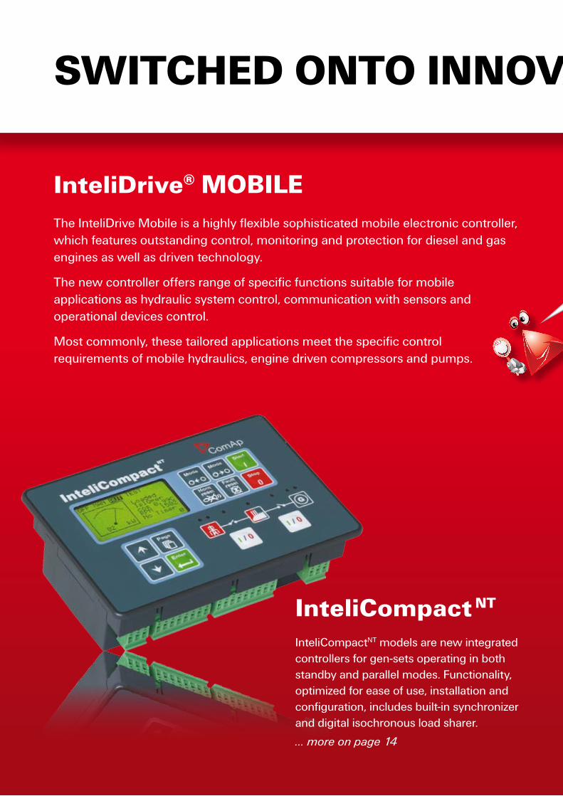
The InteliDrive Mobile is a highly flexible sophisticated mobile electronic controller, which features outstanding control, monitoring and protection for diesel and gas engines as well as driven technology.
The new controller offers range of specific functions suitable for mobile applications as hydraulic system control, communication with sensors and operational devices control.
Most commonly, these tailored applications meet the specific control requirements of mobile hydraulics, engine driven compressors and pumps.
InteliDrive® MObIlE
SwITChED OnTO InnOvaTIOn
InteliCompact nT
InteliCompactNT models are new integrated controllers for gen-sets operating in both standby and parallel modes. Functionality, optimized for ease of use, installation and configuration, includes built-in synchronizer and digital isochronous load sharer.
… more on page 14

SwITChED OnTO InnOvaTIOn
The new InteliATSNT controllers are designed to monitor the incoming AC mains supply (1 or 3 phases) for under voltage, over voltage, under frequency, over frequency and voltage unbalance.
… more on page 8
InteliaTS nT
more on page 40

wElCOME TO OUR PRODUCT GUIDE
Following the positive feedback from our first Product Guide we have updated the second issue with more
information on an ever-growing range of control products. In the meantime,
our design and development teams have worked very hard to create exciting new control solutions to
meet customers’ application needs – all of which are detailed in the
new guide.
We hope you find it just as useful and practical as before. Inside you will
find technical information, product features and functions, alongside
customer feedback on how the products have performance in the
field. Hearing what you think is very important to us, so if you would like
to share you experience of using our products please let us know by
emailing your story to [email protected]
Overall the offers a comprehensive guide to our entire range of products
and accessories. I hope you find it both helpful and invaluable.
Regards Libor Mertl – Managing Director
Power Generation Controllers 7
aTS controllers 8
Gen-set controllers 10
Generator controllers 28
Drive Power Controllers 33
Engine controllers 34
Off-road machinery controllers 40
associated Control Products 43
accessories 44
PC tools 58
Mains protections 63
Electronic potentiometers 64
applications 65
Power generation applications 66
Drive power applications 78
about Comap 89
COnTEnT
What do all those abbreviations mean? It’s easy. Go to page 62!
Ia-nT, Il-nT, IC-nT, MC-nT, IG-nT, IS-nT, IGS-nT, IM-nT, ID, Iv …

This section demonstrates the flexibility and capability of ComAp power generation control solutions by illustrating a wide range of applications including single gen-sets, multiple sets operating in parallel and complex CHP (cogeneration) applications. Each example shows how ComAp control products integrate seamlessly to deliver a complete and effective control and monitoring package for both typical and complex power applications.
Power generation applications 66
ComAp drive power control products are suitable for a wide range of diesel engine powered plant and equipment. The following applications are just a small selection to demonstrate the versatility of ComAp drive power products and accessories for use in this demanding market.
Drive power applications 78
applications
Ap
pl
iCA
tio
ns
65

A p p l i C A t i o n s / A U t o M A t i C t r A n s F E r s W i t C H
MAINS
IA-NT
IL-NT MRS 10
Start/Stop
Ready to load
Transfer demand
ENGINE ROOM
MARKET
OFFICE
SUPERMARKET
Open / delayed transition– manual transfer demand
z Stand-by gen-set. IA-NT continuously monitors mains supply for under voltage, over voltage, under frequency, over frequency and voltage unbalance. In the case of mains failure it sends a remote start command to the standby gen-set.
z IA-NT waits for “Ready To Load” signal or standby gen-set voltage – configurable - and switches load to the standby generator.
z After the mains returns the IA-NT switches load back to mains and sends remote stop command to the standby gen-set.
z Different delay intervals can be set for individual changeover phases. z The changeover can take place also on explicit demand, not only after mains failure. z ATS function works with backup battery or in reduced mode without backup battery.
z 1× IA-NT STD z 1× arbitrary gen-set controller (e.g. IL-NT MRS 10) or key start box
Description:
Scope of supply:
66

A p p l i C A t i o n s / s i n g l E g E n s E t
IL-NT MRS 16
GSM MODEM
LIGHTHOUSE
J1939
SERVICE PROVIDER
GSM MODEM#IL-NT:AL=(!Fls
Oil Pressure,!Wrn
Fuel Level)
#IL-NT:AL=(!Fls
Oil Pressure,!Wrn
Fuel Level)
Prime mover system– remote monitoring via GSM
z Manual and remote start of gen-set with electronic engine. IL-NT MRS 16 starts, controls and monitors the gen-set and controls the circuit breaker to supply the load.
z Service provider can monitor and control gen-set operation remotely via GSM modem.
z Controller sends active SMS or Emails upon alarm event. z Generator is protected by built in over/under voltage and
frequency protections and IDMT overcurrent protection. z Controller communicates with engine management unit by CAN
J1939 bus. Engine values and alarms are visible on graphical LCD screen in plain language – no need to learn cryptic flashing or numeric error codes.
z 1× IL-NT MRS 16 z 1× IL-NT RS232 z 1× GSM modem (not delivered by ComAp)
Description:
Scope of supply:
Ap
pl
iCA
tio
ns
67

A p p l i C A t i o n s / s i n g l E g E n s E t
IL-NT AMF 25
GSM MODEM
MAINS
TV
TRANSMITTER J1939
SERVICE PROVIDER
GSM MODEM#IL-NT:AL=(!Fls
Oil Pressure,!Wrn
Fuel Level)
#IL-NT:AL=(!Fls
Oil Pressure,!Wrn
Fuel Level)
Standby system– remote monitoring via GSM
z Stand-by gen-set with electronic engine. IL-NT AMF 25 continuously monitors a mains supply and automatically starts an engine and switches load to a standby generator set in case of mains failure.
z Service provider can monitor gen-set operation remotely via GSM modem.
z Generator is protected by built in over/under voltage and frequency protections and IDMT overcurrent protection.
z Controller communicates with engine management unit by CAN J1939 bus. Engine values and alarms are visible on graphical LCD screen in plain language – no need to learn cryptic flashing or numeric error codes.
z 1× IL-NT AMF 25 z 1× IL-NT RS232 z 1× GSM modem (not delivered by ComAp)
Description:
Scope of supply:
68
A p p l i C A t i o n s / p A r A l l E l i n g g E n s E t s
IGL-RA15
IC-NT SPtM
SERVICE
PROVIDER
FIREWALL
INTERNET
ENGINE ROOM
MAINS
DISTRIBUTION POINT
SURGERY
IB-Lite
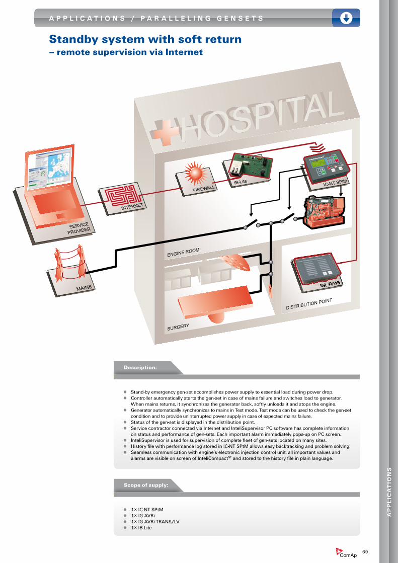
Standby system with soft return– remote supervision via Internet
z Stand-by emergency gen-set accomplishes power supply to essential load during power drop. z Controller automatically starts the gen-set in case of mains failure and switches load to generator.
When mains returns, it synchronizes the generator back, softly unloads it and stops the engine. z Generator automatically synchronizes to mains in Test mode. Test mode can be used to check the gen-set
condition and to provide uninterrupted power supply in case of expected mains failure. z Status of the gen-set is displayed in the distribution point. z Service contractor connected via Internet and InteliSupervisor PC software has complete information
on status and performance of gen-sets. Each important alarm immediately pops-up on PC screen. z InteliSupervisor is used for supervision of complete fleet of gen-sets located on many sites. z History file with performance log stored in IC-NT SPtM allows easy backtracking and problem solving. z Seamless communication with engine’s electronic injection control unit, all important values and
alarms are visible on screen of InteliCompactNT and stored to the history file in plain language.
z 1× IC-NT SPtM z 1× IG-AVRi z 1× IG-AVRi-TRANS/LV z 1× IB-Lite
Description:
Scope of supply:
Ap
pl
iCA
tio
ns
69

A p p l i C A t i o n s / p A r A l l E l i n g g E n s E t s
SERVICE
CONTRACTOR
IG-IB
FIREWALL
INTERNET
IM-NT
MAINS
CAN
2
LOAD
IC-NT MINT
IC-NT MINT
IC-NT MINTCONTROL ROOM
Multiple gensets in parallel to grid– remote monitoring and supervision via Internet
z Fully automatic system reduces electric energy bill by keeping the mains power below high tariff level during peak hours. z At the same time it accomplishes emergency standby power in case of mains failure. z Remote control and monitoring uses available factory LAN for connection between a Power house and a Control room z Service contractor connected via Internet and InteliSupervisor PC software has complete information on status and
performance of gen-sets. Each important alarm immediately pops-up on PC screen. z InteliSupervisor is used for supervision of complete fleet of gen-sets located on many sites. z Wide range of engine and generator protections, including vector-shift protection. z Automatic forward and reverse synchronization with soft load ramp-up and ramp-down during changeover. z Active and reactive load import/export control and load-sharing. z Automatic optimization of number of running sets according to load. z Peak loping controlled by built in Scheduler, engines automatically run during peak period. z History file with performance log stored in IC-NT MINT allows easy backtracking and problem solving. z Seamless communication with engine’s electronic injection control unit, all important values and alarms are visible on
screen of InteliCompactNT and stored to the history file in plain language.
z 3× IC-NT MINT z 3× IG-AVRi z 3× IG-AVRi-TRANS/LV
z 1× IM-NT z 1× IG-IB z 1× IG-IB3 dongle
Description:
Scope of supply:
70

A p p l i C A t i o n s / p A r A l l E l i n g g E n s E t s
Rental sets
IG-NT
IM-NT
IG-NT
IG-NT
LOAD
z Containerized rental gen-sets can be used for maintenance of power lines without interruption of power delivery to end consumer.
z Gen-sets are connected one-by-one to mains at the consumer’s end and manually loaded. Power line is then manually disconnected and consumer is powered from generators running in parallel.
z The group of gen-sets is reverse synchronized to mains after finalization of maintenance on power line. InteliMainsNT keeps generators and mains in synchronism enabling manual reconnection to power line.
z InteliMainsNT is built in a small shock proof suitcase. z Interconnection of containers is done by color coded not-interchangeable connectors. z Each gen-set can be used in Stand-by, Single parallel to mains and Multiple parallel modes according to the
position of Mode selector switch. z Frequency selector enables switching between 50Hz/230V and 60Hz/277V mains.
z 3× IG-NT z 3× IGS-NT-LSM+PMS dongle z 3× IG-AVRi
z 3× IG-AVRi-TRANS/LV z 1× IM-NT
Description:
Scope of supply:
Ap
pl
iCA
tio
ns
71

A p p l i C A t i o n s / p A r A l l E l i n g g E n s E t s
INTERNET
IM-NT
IG-NT
IM-NT
J1939
IG-NT
J1939
J1939 BTB
CAN
2
IM-NT
PLC
IG-NT
IG-NT
ENGINE ROOM 1
PRODUCTION HALL 1
IM-NT
IG-NT
IM-NT
J1939
IG-NT
J1939
J1939
CAN
2
LAN / W
AN
IG-NT
IG-NT
IG-IB
ENGINE ROOM 2
PRODUCTION HALL 2
CONTROL ROOM
MAINS
MAINS
GATE
FACTORY Ltd. F
Complex installation– multiple grids
z Essential load is fed by two mains feeders during normal operation to achieve maximum reliability of the power delivery. Bus-tie breaker (BTB) is closed.
z Complex switching algorithm running in external PLC defines which breakers are opened and which are closed independent on availability of two mains and gen-sets.
z Reverse synchronizing on both feeders and on bus-tie breaker is accomplished by 5 InteliMainsNT modules controlled by external PLC.
z Active and reactive load-sharing can operate in two modes: – Sharing the load between all running gen-sets – if BTB is closed – Sharing the load in two independent groups – if BTB is opened
z Automatic power dependant start/stop can operate in two modes as well: – Running on all gen-sets – if BTB is closed – Running in two independent groups – if BTB is opened
z All controllers are interconnected by one CAN bus all the time, disregarded if BTB is closed or open, no need for relays reconnecting the CAN bus.
z Complete system is remotely controlled and supervised from Control room connected via company LAN and IG-IB to all controllers.
Description:
72

INTERNET
IM-NT
IG-NT
IM-NT
J1939
IG-NT
J1939
J1939 BTB
CAN
2
IM-NT
PLC
IG-NT
IG-NT
ENGINE ROOM 1
PRODUCTION HALL 1
IM-NT
IG-NT
IM-NT
J1939
IG-NT
J1939
J1939
CAN
2
LAN / W
AN
IG-NT
IG-NT
IG-IB
ENGINE ROOM 2
PRODUCTION HALL 2
CONTROL ROOM
MAINS
MAINS
GATE
FACTORY Ltd. F
z 6× IG-NT z 6× IGS-NT-LSM+PMS dongle z 6× IG-AVRi
z 6× IG-AVRi-TRANS/LV z 5× IM-NT z 1× IG-IB
z 1× IG-IB 15 dongle z 1× optional PLC
(not delivered by ComAp)
Scope of supply:
Ap
pl
iCA
tio
ns
73

A p p l i C A t i o n s / p A r A l l E l i n g g E n s E t s
RECEPTION
KITCHEN
ROOMS
LIFT
ENGINE ROOM
CONTROL ROOM
IM-NT
MAINS
IS-NT
J1939
J1939
CAN
2
IS-NT
INTELIVISION
INTELIVISION
Standby system with load shedding– advanced displays
z The system guarantees emergency standby power in case of mains failure. z IM-NT provides AMF function and activates mains to gen-sets changeover in the case of mains failure no break return to mains. z Load shedding can take place during the changeover to trip the unessential load when gen-set goes to island. z Gen-set starts, the power is ramped-up, load is reconnected. The second gen-set is started if needed (more load requires more gen-set power). z Automatic forward and reverse synchronisation with soft load ramp-up and ramp-down during changeover is available. z Wide range of engine and generator protections, including vector shift protection are standard features. z Automatic optimization of number of running sets according to load can be selected. z Automatic equalization of running hours of particular engines is available. z The second gen-set can be used as a backup set. z History file with performance log stored in IS-NT allows easy backtracking and problem solving.
z 2× IS-NT z 2× IGS-NT-LSM+PMS dongle
z 2× InteliVision z 1× IM-NT
z 2× IG-AVRi z 2× IG-AVRi-TRANS/LV
Description:
Scope of supply:
74
A p p l i C A t i o n s / p A r A l l E l i n g g E n s E t s
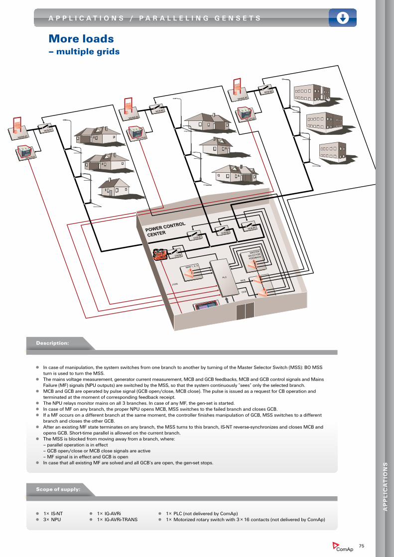
More loads– multiple grids
GCB #3
CGCB
J1939
GCB #1
MAINS #1
MASTER
SELECTOR
FEEDBACK
MASTER
SELECTOR
MCB #1
MAN 1, 2, 3
GCB #2
MAINS #2
MCB #2
MAINS #3
MCB #3
IS-NT
NPU-FUV
NPU-FUV
NPU-FUV
MCB
GCB
1, 2, 3
PLC
POWER CONTROL
CENTER
z In case of manipulation, the system switches from one branch to another by turning of the Master Selector Switch (MSS): BO MSS turn is used to turn the MSS.
z The mains voltage measurement, generator current measurement, MCB and GCB feedbacks, MCB and GCB control signals and Mains Failure (MF) signals (NPU outputs) are switched by the MSS, so that the system continuously “sees” only the selected branch.
z MCB and GCB are operated by pulse signal (GCB open/close, MCB close). The pulse is issued as a request for CB operation and terminated at the moment of corresponding feedback receipt.
z The NPU relays monitor mains on all 3 branches. In case of any MF, the gen-set is started. z In case of MF on any branch, the proper NPU opens MCB, MSS switches to the failed branch and closes GCB. z If a MF occurs on a different branch at the same moment, the controller finishes manipulation of GCB, MSS switches to a different
branch and closes the other GCB. z After an existing MF state terminates on any branch, the MSS turns to this branch, IS-NT reverse-synchronizes and closes MCB and
opens GCB. Short-time parallel is allowed on the current branch. z The MSS is blocked from moving away from a branch, where:
– parallel operation is in effect – GCB open/close or MCB close signals are active – MF signal is in effect and GCB is open
z In case that all existing MF are solved and all GCB’s are open, the gen-set stops.
z 1× IS-NT z 3× NPU
z 1× IG-AVRi z 1× IG-AVRi-TRANS
z 1× PLC (not delivered by ComAp) z 1× Motorized rotary switch with 3 × 16 contacts (not delivered by ComAp)
Description:
Scope of supply:
Ap
pl
iCA
tio
ns
75

A p p l i C A t i o n s / p A r A l l E l i n g g E n s E t s
RECEPTION
OFFICE
ENGINE ROOM
POOL
Heat exchanger/boiler Exhaust
Heating water
Fuel line
Engine
Generator Electrical supply
Electricalpanel
IS-AIN8
I-AOUT8
IS-NT
MAINS
IS-AIN8
CAN1
IS-BIN16/8
IG-IB
Pre
ssur
e
Tem
pera
ture
Tem
pera
ture
Temperature
Pressure
Tem
pera
ture
Pre
ssur
e
Tem
pera
ture
Pre
ssur
e
Pressure
Temperature
Temperature
Tem
pera
ture
Tem
pera
ture
Tem
pera
ture
Pum
pP
ump
Vent
ilatio
n
Hea
t (Jo
ule)
CONTROL ROOM
LAN
CAN2
2009
2009
Combined heat and power (ChP)– cogeneration
76

RECEPTION
OFFICE
ENGINE ROOM
POOL
Heat exchanger/boiler Exhaust
Heating water
Fuel line
Engine
Generator Electrical supply
Electricalpanel
IS-AIN8
I-AOUT8
IS-NT
MAINS
IS-AIN8
CAN1
IS-BIN16/8
IG-IB
Pre
ssur
e
Tem
pera
ture
Tem
pera
ture
Temperature
Pressure
Tem
pera
ture
Pre
ssur
e
Tem
pera
ture
Pre
ssur
e
Pressure
Temperature
Temperature
Tem
pera
ture
Tem
pera
ture
Tem
pera
ture
Pum
pP
ump
Vent
ilatio
n
Hea
t (Jo
ule)
CONTROL ROOM
LAN
CAN2
2009
2009
z CHP (also known as cogeneration) is the most efficient way of using fossil or renewable fuel. z It provides output of power (3 phase electricity) and heat (hot water), which is recovered from
the cooling system and flue gases. z The overall power and heat consumption of the application can be covered by the CHP system.
Export of energy or heat is also possible. z All analog and binary signals both from engine and from auxiliary systems are measured by
IS-NT and its accessory modules. z Complete control of auxiliary technologies is done by built-in PLC module. z All data measured from auxiliary equipment are stored in a history file. z Remote control and monitoring is available. z Only the most important Analog Inputs / Outputs and Binary Inputs / Outputs connections
are drawn.
z 1× IS-NT z 1× IS-BIN16/8 z 2× IS-AIN8 z 1× I-AOUT8 z 1× IG-AVRi z 1× IG-AVRi-TRANS/LV z 1× IG-IB
Description:
Scope of supply:
Having problems with the complexity of your current control system? InteliSysNT
integrates all functions in one convenient solution.
Ap
pl
iCA
tio
ns
77
A p p l i C A t i o n s / i n D U s t r i A l E n g i n E s
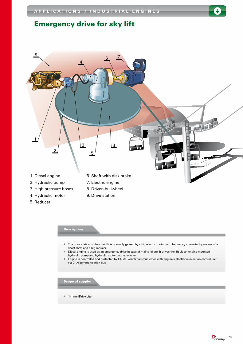
Emergency drive for sky lift
1
23
4
5
6 7
8
9
1. Diesel engine
2. Hydraulic pump
3. High pressure hoses
4. Hydraulic motor
5. Reducer
6. Shaft with disk-brake
7. Electric engine
8. Driven bullwheel
9. Drive station
z The drive station of the chairlift is normally geared by a big electric motor with frequency converter by means of a short shaft and a big reducer.
z Diesel engine is used as an emergency drive in case of mains failure. It drives the lift via an engine-mounted hydraulic pump and hydraulic motor on the reducer.
z Engine is controlled and protected by ID-Lite, which communicates with engine‘s electronic injection control unit via CAN communication bus.
z 1× InteliDrive Lite
Description:
Scope of supply:
78

A p p l i C A t i o n s / i n D U s t r i A l E n g i n E s
hydraulic of shearing machine
Requested
Pressure
+
–
Previous
FollowingError
–
+ x Kd
+
++
EngineHP
x Kp
+ il
x Ki
+
PSCurrent Pressure
Current Following Error
Error Integral
(n)
(n-1)
Desired = proportional gain
= derivative gain
= integral gain
= integral limit
= hydraulic pump
= pressure sensonr
KpKd
Kiil
HPPS
HYDRAULIC PUMP
DIESEL ENGINE
HYDRAULIC RESERVOIR
J1939Speed request
Pressure
CONTROL VALVES
ID-DCU
z Mobile hydraulic shear balers and fragmentizers, which are driven by diesel engines with electronic fuel injection and meet all of the latest emission standards.
z Subject machines are mainly used to compress scrap-metal and cut it into pieces, very useful for further processing.
z The ID-DCU Industrial oversees the complete, control, monitoring, fault-logging and protection of the machine operation.
z All information is visualized on the screen, including faults transmitted via CAN from the engine mounted ECU. z The hydraulic sequences are controlled via integrated and enhanced PLC logics, as well as the engine-speed load
is controlled via PID-loops. z The advanced bi-directional CAN-Bus communication helps simplify the wiring to the engine.
z 1× ID-DCU Industrial
Description:
Scope of supply:
Ap
pl
iCA
tio
ns
79

A p p l i C A t i o n s / i n D U s t r i A l E n g i n E s
Irrigation pump system
CONTROL ROOM
Requiredflow
PID loopSpeedrequest
ID-DCU
Pressure
Temperature
Fuel solenoid
J1939
Starter
Engine
ID-SCM
PumpFlow meter
WATER
Requiredflow
PID loopSpeedrequest
ID-DCU
Pressure
Temperature
Fuel solenoid
J1939
Starter
Engine
ID-SCM
PumpFlow meter
WATER
Requiredflow
PID loopSpeedrequest
ID-DCU
Pressure
Temperature
Fuel solenoid
J1939
Starter
Engine
ID-SCM
PumpFlow meter
WATER
Requiredflow
PID loopSpeedrequest
ID-DCU
Pressure
Temperature
Fuel solenoid
J1939
Starter
Engine
ID-SCM
PumpFlow meter
WATER
z Systems involving large numbers (over 10) of engine driven irrigation pumps controlled and monitored from one supervision point by radio or GSM modems.
z InteliDrive makes complete control, monitoring and protection of the engine. z Water flow from a pump is measured by flow-meter with impulse output. Frequency of pulses, that is directly
proportional to flow of water, is measured by module ID-SCM. z Variable speed engine enables to change water flow according momentary need. z Required flow is received via radio or GSM modem from a central supervision point and maintained by PID
loop build in InteliDrive.
z 1× ID-DCU Industrial z 1× ID-SCM z 1× Radio or GSM modem (not delivered by ComAp) z 1× Flow-meter (not delivered by ComAp)
Description:
Scope of supply:
80

A p p l i C A t i o n s / i n D U s t r i A l E n g i n E s
Gas compressor
CONTROL ROOM
4-20mA/psi
4-20mA/psi
CmpH
CmpH
DP limit OFF
DP Limit ON
SP limit OFF
SP Limit ON
ORDP Limit
Out
SP LimitOut
SP&DP Limit
RPM lim 900
RPM lim 1500
LowestRPM
ToMAX
RAMP
SW
Output to Engine
Speed Out
Discharge
pressure
DP Sensor
Suction
pressure
SP SensorCmpH
Up limit OFF
Up Limit ON SpeedUp AND
PLC value Del3
SpUpA
ToSpUpOR
AND
SpRqRPM
ToSpUpSpUp
BO SpUp
BO SpDn
SpDn
ToSpDn
OR
OR
MAX
AND
AND
1
2
4
3
9
18
20
17
19
8
22
7
15
ID-SCM
FLOW METER
INTELIDRIVE DCU
INDUSTRIAL
SUCTION
PRESSURE
SENSOR
DISCHARGE
PRESSURE
SENSOR
Fuel solenoidStarter
Temperature
RPM
Pressure
ENGINE
EARTH
COMPRESSOR
Speed governor
4-20mA/psi
4-20mA/psi
CmpH
CmpH
DP limit OFF
DP Limit ON
SP limit OFF
SP Limit ON
ORDP Limit
Out
SP LimitOut
SP&DP Limit
RPM lim 900
RPM lim 1500
LowestRPM
ToMAX
RAMP
SW
Output to Engine
Speed Out
Discharge
pressure
DP Sensor
Suction
pressure
SP SensorCmpH
Up limit OFF
Up Limit ON SpeedUp AND
PLC value Del3
SpUpA
ToSpUpOR
AND
SpRqRPM
ToSpUpSpUp
BO SpUp
BO SpDn
SpDn
ToSpDn
OR
OR
MAX
AND
AND
1
2
4
3
9
18
20
17
19
8
22
7
15
ID-SCM
FLOW METER
INTELIDRIVE DCU
INDUSTRIAL
SUCTION
PRESSURE
SENSOR
DISCHARGE
PRESSURE
SENSOR
Fuel solenoidStarter
Temperature
RPM
Pressure
ENGINE
EARTH
COMPRESSOR
Speed governor
z Gas compressor is driven by a combustion engine. z InteliDrive makes complete control, monitoring and protection of the engine and compressor. z Sophisticated control algorithm using build-in PLC modules accomplishes optimal running conditions for the
compressor. z Speed of the engine is determined according to the suction and discharge pressures of the compressor. z Additional unload and by-pass valves are controlled by InteliDrive in dependence on both suction and
discharge pressures.
z 1× ID-DCU Industrial z 1× ID-SCM z 1× Radio or GSM modem (not delivered by ComAp) z 1× Flow-meter (not delivered by ComAp)
Description:
Scope of supply:
Ap
pl
iCA
tio
ns
81

A p p l i C A t i o n s / M A r i n E E n g i n E s
Ship control system
ENGINE ROOM 1
TRANSMISSION HYDRAULIC
CLUTCH
ENGINE
ID-DCU
MARINE
ID-DCU
MARINE
MODBUS
DISPLAY PANEL
BRIDGE
ETHER
NET
2 1 ECU
ECM
J1939
J1939
J1939
J1587
J1587
J1587
CLUTCH CONTROL
ID-DCU
MARINE
SPLITER
MODBUS
TCP RTU
MODBUS
MODBUS
TCP RTU
MODBUS
CAN2
MODBUS
TCP RTU
MODBUS
CLUTCH CONTROL
4 - 20 mA R
EQU
ESTED SPEED
4 - 20 mA R
EQU
ESTED SPEED
ENGINE ROOM 2
2
1
2
2x 4/20mA
4/20mA
z Small ferries typically feature two propellers, one in bow and one in stern. Propellers can rotate by 360° to give requested maneuverability to the ferry.
z Each propeller is driven by two engines located in two separate engine rooms. z In each engine room is also one auxiliary gen-set. z Propulsion engines are controlled by InteliDrive Marine, in PROP configuration, via J1939 bus. Redundant
J1587 bus is used in case of J1939 failure. z Requested speed is defined by 4-20mA signal from the bridge. z InteliDrive controllers make propulsion load-sharing to keep engines evenly loaded. z Engines of auxiliary gen-sets are controlled by InteliDrive Marine in AUX configuration. z InteliDrive controllers communicate to a ship’s control and visualization system via Modbus RTU/TCP
converter and Ethernet bus. z Optimal configurable structure of InteliDrive’s Modbus message together with high communication speed
of Ethernet bus gives immediate information on engine speed and torque required on the bridge of a quickly maneuvering ship.
Description:
82

ENGINE ROOM 1
TRANSMISSION HYDRAULIC
CLUTCH
ENGINE
ID-DCU
MARINE
ID-DCU
MARINE
MODBUS
DISPLAY PANEL
BRIDGE
ETHER
NET
2 1 ECU
ECM
J1939
J1939
J1939
J1587
J1587
J1587
CLUTCH CONTROL
ID-DCU
MARINE
SPLITER
MODBUS
TCP RTU
MODBUS
MODBUS
TCP RTU
MODBUS
CAN2
MODBUS
TCP RTU
MODBUS
CLUTCH CONTROL
4 - 20 mA R
EQU
ESTED SPEED
4 - 20 mA R
EQU
ESTED SPEED
ENGINE ROOM 2
2
1
2
2x 4/20mA
4/20mA
z 6× ID-DCU Marine z 6× ID-RPU z 4× ID-COM z 6× Modbus RTU/TCP converter (not delivered by ComAp)
Scope of supply:
No ordinary engine controller features engine speed control,
monitoring, propulsion and load sharing. With ID-DCU Marine you
get all this and more!
Ap
pl
iCA
tio
ns
83

A p p l i C A t i o n s / M o B i l E M A C H i n E r Y
wheel loader
CONTROL VALVES
RPM Pickup Speed Governor Fuel Solenoid Starter
Coolant TempLube Oil Press
High Temp
Low Oil Press
Fuel LevelID-MOBILE
Proportional Valve
On-Off Valve
4
8
CAN
ID-MOBILECAN
z Wheel loader application – where a standard (non-electronic) engine drives a hydraulic pump and produces high-pressure oil drives wheels through hydro-motors delivers power to all hydraulic cylinders and pistons.
z Two InteliDrive Mobile (ID-Mobile) controllers are utilized in the application. The first one, located in the driver’s cabin, receives commands from the driver via two joysticks and various switches giving him complete information on machine status via a large color screen and a few pilot-lights. The second InteliDrive Mobile, located on the machine frame, controls and monitors the engine and various hydraulic control valves.
z Communication between the two InteliDrive controllers and the on-board display is via CAN line. This makes the system wiring and integration very simple.
z All values, warnings and fault codes from the engine are displayed on the on-board display. z Control of the bucket level is via proportional hydraulic valves, control of wheel speed with anti-slip protection
is via PWM hydraulic valves and all other control loops are realized by standard integrated free configurable control blocks.
z 2× InteliDrive Mobile z 1× VGA Mobile display
Description:
Scope of supply:
84

A p p l i C A t i o n s / M o B i l E M A C H i n E r Y
Shunting loco
RPM
J1939
CAN
EMS
Compressor
Cooling
Air SYST
Brakes
Air SYST
Air
Hydro-Turbo
ID-MOBILE
InteliVision
z The shunting locomotive re-power application uses an InteliDrive Mobile (ID-Mobile) for the complete control, monitoring and protection of the Volvo D16 engine which drive a Voith Hydro – Turbo gear-box for propulsion via a system of push-rods. It is also used for a number of auxiliary functions which includes the air-system compressor or for the vehicle speed by monitoring the RPM in the Voith Hydro – Turbo.
z Full communication between engine, ID-Mobile and the two InteliVision displays is achieved with J1939 CAN bus – making the system wiring and integration very simple.
z All values, warnings and fault codes from the engine (EMS) are displayed on the two large InteliVision displays, located on both sides of the locomotive cabin.
z Smooth take-off and moving, with wheel-slip limitation, is controlled by Ramp function – made possible with the standard ID-Mobile integrated, free configurable PLC logic.
z 1× InteliDrive Mobile z 2× InteliVision
Description:
Scope of supply:
Ap
pl
iCA
tio
ns
85

A p p l i C A t i o n s / M o B i l E M A C H i n E r Y
Crusher
= pressure sensorPS
HydraulicPump
ECU
CAN
DISPLAY
CAN
ON/OFF VALVES
PROP. VALVES
Motion Control
Crushing Chamber
Adjustment
Grizzly Feeder Speed Control
HydraulicValves
ID-MOBILE
86

HydraulicPump
ECU
CAN
DISPLAY
CAN
ON/OFF VALVES
PROP. VALVES
Motion Control
Crushing Chamber
Adjustment
Grizzly Feeder Speed Control
HydraulicValves
ID-MOBILE
z Crusher application - where an electronic engine drives a hydraulic pump. The InteliDrive Mobile (ID-Mobile) controller oversees the complete control, monitoring and protection of the engine and all driven machinery. The continuous speed control of a grizzly feeder together with the adjustment of the crushing chamber prevents the crusher from blockages and reduces wear on critical components.
z Communication between engine, InteliDrive Mobile and a display is via CAN bus line. This makes the system wiring and integration very simple.
z Visualization of the most important parameters of the machine as well as selection of the operational mode of the machine is done by a display located near the InteliDrive Mobile controller.
z Control of machine operation is realized by standard integrated, free configurable PLC logic.
z 1× InteliDrive Mobile z 1× Monochrome or colour display
Description:
Scope of supply:
Ap
pl
iCA
tio
ns
87

USa
netherlands Slovakia
Canada
“We admire ComAp products because of their innovative features. These include forward looking technological development of monitoring; the ability to solve non-standard customers’ requirements and the huge spectrum of opportunities for running of power supplies.”
peter ŠiškaChief of Application and costing estimation departmentwww.elteco.sk
“ComAp’s compressor and engine control panel solution optimizes natural gas production on Boss’s booster units by providing accurate process control using digital pressure transducers.Our customers are very happy with its event history capabilities as well as its compressor and engine protective features. We also value the fact that the ComAp ID-DCU panel is fully compatible with future electronic emission certified engines and control capabilities. BOSS Industries has standardized on the ComAp panel for our gas well booster compressor units.“
Ed KetchamVP Saleswww.bossair.com
“All our generator sets and propulsion engines are equipped with a ComAp engine controller, ID-DCU Marine. They are approved by all major Ship Classification Companies. The units fulfill our high quality standards, have many applications and are widely used. Remote monitoring is one of them, which Sandfirden Technics is using in some cases.“
Harry JasperService Departmentwww.sandfirden.nl
”When I first saw InteliVision, I immediately recognized its potential for our power generation systems. The large easy to read color display and customer-friendly interactivity is precisely what our customers have been looking for. We have already installed systems with InteliVision and received very positive feedback from our customers on the units performance.“
santokh sahotaEngineering Managerwww.simson-maxwell.com
boss Industries
Sandfirden Technics ElTECO
Simson-Maxwell
Satisfied Customers worldwide
88

about Comap
89
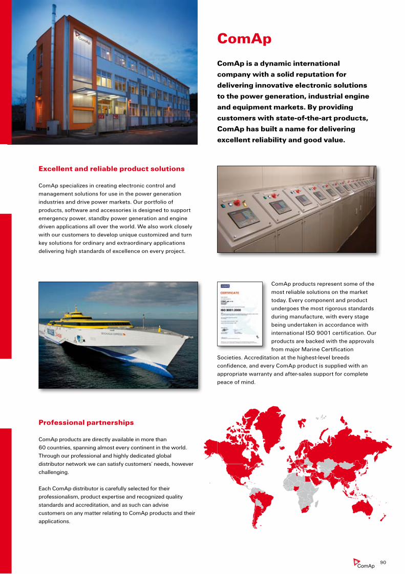
Excellent and reliable product solutions
ComAp specializes in creating electronic control and management solutions for use in the power generation industries and drive power markets. Our portfolio of products, software and accessories is designed to support emergency power, standby power generation and engine driven applications all over the world. We also work closely with our customers to develop unique customized and turn key solutions for ordinary and extraordinary applications delivering high standards of excellence on every project.
ComAp products represent some of the most reliable solutions on the market today. Every component and product undergoes the most rigorous standards during manufacture, with every stage being undertaken in accordance with international ISO 9001 certification. Our products are backed with the approvals from major Marine Certification
Societies. Accreditation at the highest-level breeds confidence, and every ComAp product is supplied with an appropriate warranty and after-sales support for complete peace of mind.
Professional partnerships
ComAp products are directly available in more than 60 countries, spanning almost every continent in the world. Through our professional and highly dedicated global distributor network we can satisfy customers’ needs, however challenging. Each ComAp distributor is carefully selected for their professionalism, product expertise and recognized quality standards and accreditation, and as such can advise customers on any matter relating to ComAp products and their applications.
Comap
Comap is a dynamic international
company with a solid reputation for
delivering innovative electronic solutions
to the power generation, industrial engine
and equipment markets. by providing
customers with state-of-the-art products,
Comap has built a name for delivering
excellent reliability and good value.
90
People make the difference
ComAp‘s key strengths are flexibility, experience, knowledge and enthusiasm. This blend of values defines our personality and gives you the assurance of a truly honest and positive relationship. By
supporting our people, investing in their development and encouraging creativity, our teams work hard to find new opportunities, technologies and solutions that enable us to successfully help our customers solve their problems effectively.
At ComAp, we believe passionately in the importance of continuously developing new technology along with forward thinking software and hardware to maintain the enviable position as worldwide leader in communication and control for power generation and drive power applications.
At the heart of this process is a strong desire to exceed our customers’ expectations by finding outstanding solutions for them and drawing upon the company’s most valuable asset – people. Over 80 % of ComAp employees are graduates with specialized electronic and programming knowledge appropriate to
the innovative development of market-orientated engine management systems. This unique know-how is matched by ComAp’s significant investment at every stage of the research and development process, resulting in the creation of leading edge modern development facilities. ComAp consistently set high standards, reflected in our third place in the ’Best Employers Study in the Czech Republic’ (conducted by Hewitt Associates) in consecutive years (2006 and 2007).
Comap Systems
ComAp’s expertise extends beyond innovative controllers to include a range of subsidiary businesses specializing in related services including bi-fuel conversions, power energy systems solutions and electronic component distribution.
These subsidiaries are located in key strategic regions around the world ensuring our customers benefit from local capability coupled with global reach. Most of them are named ComAp Systems and more information is available on each business at www.comapsystems.com.
Key Milestones
1991Establishment of ComAp.
1993Successful commissioning of four Gen-set Control Systems made by ComAp on Mediterranean islands.
1994MX controller, the second generation of ComAp’s gen-set control systems, was launched.
1996PX, the revolutionary gen-set controller with configurable input and outputs, was developed.
1999The strategic co-operation with HuegliTech Company significantly increased our distribution network.
2000InteliGen, the first member of the Inteli family and flagship of our gen-set control systems, was released.
2001ComAp Ltd. – 100 % UK based ComAp subsidiary was established close to Bristol.
2002InteliSys, our top end product dedicated to CHP and large engine control applications, was released. New mid-range product InteliLite was launched for AMF and MRS applications.
2004InteliDrive controller for non gen-set, engine driven applications was released.
2006ComAp LLC – ComAp subsidiary to promote products in the USA and Canada.
2007InteliVision – the first color display unit in power generation field.
2008InteliCompact – controller for simple paralleling gensets.
91

Comap, spol. s r. o.
Kundratka 2359/17 • 180 00 Praha 8 • Czech Republic
Phone: + 420 246 012 111 • Fax: + 420 266 316 647
[email protected] • www.comap.cz
Manufacturer
local Distributor / partner
© ComAp. 2009-01/CpCEprgU. All rights reserved.
specifications in this product guide are subject to change without notice.
We are looking forward to your visit.
ulmoser
Hügli Logo mit Adresse


![260-2501 Tipping Bucket Rain Gauge User ManualE } À > Ç v Æ } } ] } v z z z z z z z z z z z z z z z z z z z z z z z z z z z z z z z z z z z z z z z z z z z z z z z z z z z z z z](https://static.fdocuments.us/doc/165x107/60df9ff0f4aa6921e4565fc2/260-2501-tipping-bucket-rain-gauge-user-manual-e-v-v-z-z.jpg)


![for model : TM-9200s-U240n-5A TM-9300s-U240n-5A DELAB ... 2013.pdf · (refer to IDMT Graph) Select the desired IDMT curve using the [ Up / (+) ] or [ Down / (-) ] button. Newly selected](https://static.fdocuments.us/doc/165x107/60dab49f5dabad678957ab66/for-model-tm-9200s-u240n-5a-tm-9300s-u240n-5a-delab-2013pdf-refer-to-idmt.jpg)


![I De [I], [Z] · PDF file'pms W wifl b props& a nw vim of projacts whkh ace p&mimtly lydc r- &mi tscb cantria ... idmt~ed as one of fh top lea concern of IS weuIive~ tvcettfly](https://static.fdocuments.us/doc/165x107/5aa6117f7f8b9ac8748dfb25/i-de-i-z-pms-w-wifl-b-props-a-nw-vim-of-projacts-whkh-ace-pmimtly-lydc-r-mi.jpg)

