
Product Description June 2001 AMA...
64
ABB Industry Oy $%% Product Description ,QGXFWLRQ0DFKLQHV June 2001 AMA 315/355/400
Transcript of Product Description June 2001 AMA...
ABB Industry Oy
Product Description
June 2001 AMA 315/355/400

This document has been carefully checked. However, if any errors are found, we ask the user to notify us as soonas possible.
The specified data is only a description of this product and should not be interpreted as binding characteristics. Inthe interest of our customers we continually improve our product to the latest technical development. Deviationsbetween products and product descriptions or these operating instructions can, therefore, occur.
We reserve all rights in this document and in the information contained therein. Reproduction, use or disclosureto third parties without express authority is strictly forbidden.

Data subject to change without notice. Copyright 2001, ABB Industry
1. General________________________________________________________________________5
2. Features _______________________________________________________________________5
3. Cooling & Enclosures_____________________________________________________________53.1 Weather Protected Type I (ODP/WP-I) or IC01, IP23 ______________________________________ 53.2 Weather Protected Type II (WP-II) or IC01, IP24W________________________________________ 63.3 Totally-enclosed water-air-cooled (TEWAC) or IC81W, IP55 ________________________________ 63.4 Totally-enclosed air-to-air-cooled (TEAAC) or IC611, IP55 __________________________________ 6
4. Mounting_______________________________________________________________________74.1 Standard mounting arrangements _____________________________________________________ 7
5. Direction of rotation ______________________________________________________________7
6. Stator Windings and Insulation _____________________________________________________7
7. Sound Levels ___________________________________________________________________77.1 Special Sound Level _______________________________________________________________ 8
8. Vibration Severity__________________________________________________________________8
9. Ambient Temperature ____________________________________________________________89.1 Standard ambient temperature _______________________________________________________ 89.2 Special ambient temperature_________________________________________________________ 8
10. Altitude ________________________________________________________________________810.1 Standard altitude __________________________________________________________________ 810.2 Special altitude____________________________________________________________________ 8
11. Rotor and Shaft _________________________________________________________________8
12. Couplings ______________________________________________________________________8
13. Bearings _______________________________________________________________________913.1 Standard antifriction bearings in horizontally mounted machines _____________________________ 913.2 Standard antifriction bearings in vertically mounted machines ______________________________ 1013.3 Standard sleeve bearings in horizontally mounted machines _______________________________ 1113.4 Special bearings and bearing accessories _____________________________________________ 12
14. Conduit Boxes (Terminal Boxes) ___________________________________________________1214.1 Standard main conduit boxes _______________________________________________________ 1214.2 Standard auxiliary conduit box_______________________________________________________ 1314.3 Special conduit boxes _____________________________________________________________ 13
15. Corrosion Protection_____________________________________________________________1315.1 Standard painting (Paint system 1) ______________________________________________________ 1315.2 Special painting __________________________________________________________________ 13
16. Accessories ___________________________________________________________________1316.1 Standard accessories _____________________________________________________________ 1316.2 Optional accessories ______________________________________________________________ 13
17. Packing_______________________________________________________________________1317.1 Standard packing_________________________________________________________________ 1317.2 Special packing __________________________________________________________________ 13
18. Testing _______________________________________________________________________1318.1 Routine test _____________________________________________________________________ 1318.2 Special testing ___________________________________________________________________ 14
19. Documentation _________________________________________________________________1419.1 Standard documentation ___________________________________________________________ 1419.2 Special documentation_____________________________________________________________ 14
!" #
20. Control and Protective Equipment __________________________________________________15
Data subject to change without notice. Copyright 2001, ABB Industry
20.1 Temperature control ______________________________________________________________ 1520.2 Space heaters ___________________________________________________________________ 1520.3 Air Filters for Weather Protected Machines (WP-II or IP24W) ______________________________ 1520.4 Differential Pressure Switch for condition monitoring of filters ______________________________ 1520.5 Leakage Detector for heat exchangers (TEWAC or IC81W) _______________________________ 15
21. Testing _______________________________________________________________________1521.1 Type tests ______________________________________________________________________ 15
22. Foundation Equipment ___________________________________________________________1622.1 Foundation studs_________________________________________________________________ 1622.2 Sole plates _____________________________________________________________________ 1622.3 Shims _________________________________________________________________________ 16
$"%
23. Control and Protective Equipment __________________________________________________1723.1 Temperature control ______________________________________________________________ 1723.2 Transmitters for RTDs and/or Thermocouples __________________________________________ 1823.3 Vibration Monitoring ______________________________________________________________ 1823.4 Space heaters ___________________________________________________________________ 2023.5 Pulse Encoders __________________________________________________________________ 20
24. Bearings & Bearing Accessories ___________________________________________________2024.1 Bearing housing seals_____________________________________________________________ 2024.2 Bearing insulation ________________________________________________________________ 2024.3 Grease box for excess and waste grease ______________________________________________ 2124.4 Constant level oiler for self-lubricated sleeve bearings____________________________________ 21
25. Conduit Boxes (Terminal Boxes) ___________________________________________________2125.1 NEMA Type II Conduit Box _________________________________________________________ 2125.2 Extra Long Leads ________________________________________________________________ 21
26. Painting_______________________________________________________________________2226.1 Special color shade_______________________________________________________________ 2226.2 Special painting (Paint system 2) ____________________________________________________ 2226.3 Special painting (Paint system 3) ____________________________________________________ 22
27. Special Sound Level_____________________________________________________________2227.1 Low noise WP-II (IC01, IP24W) _____________________________________________________ 2227.2 Low noise TEAAC (IC611, IP55)_____________________________________________________ 22
28. Packing_______________________________________________________________________23
29. Documentation _________________________________________________________________23
&'( )
40. NEMA Machines________________________________________________________________24
41. IEC Machines __________________________________________________________________24
(*
32. Starting capacity________________________________________________________________45
33. 60 Hz NEMA machines __________________________________________________________46
34. 50 Hz IEC machines_____________________________________________________________49
+,- .

Data subject to change without notice. Copyright 2001, ABB Industry
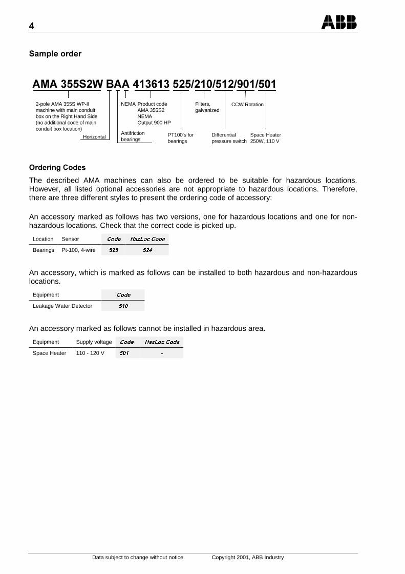
When placing an order, the machine type, size and product code must be specified. Ifvariants or optional accessories are chosen, the corresponding codes must be alsoincluded.
!""" # $$$ $$$%%%1 2 3 4 5 6 7 8 9 11 1210
1 Machine Family2 Frame size in mm, 315, 355 or 400, followed by S3 Number of poles4 Cooling and Enclosure
D = WP-I [IC01, IP23]W = WP-II [IC01, IP24W]L = TEWAC [IC81W, IP55]A = TEAAC [IC611, IP55]
5 ! Mounting arrangementB = horizontal (F-1 / F-2 or IM 1001)V = vertical (IEC only, IM 3011)
6 Bearing typeA = antifrictionS = sleeve
7 StandardA = NEMA S = CSA, NEMA dimensions [in]I = IEC C = CSA, IEC dimensions [mm]
8 " Protection for hazardous locations (optional)O = Class I Division 2 T3 K = Class II Division 2 Group F, GR = Class I Zone 2 Ex nA II T3 F = Class III (fibre environments)
&' Points 8 and 9, factory fills.9 ( Indication of special construction (not compulsory)10 ) Location of manufacture
H = Helsinki (Finland) C = Champagne (France)
11 # Product code specifies voltage, frequency and output. See rating lists.12 $$$ Variant codes, see accessory/variant list.
Some optional features in the standard construction must be specified with a variant code:
&RGH
Direction of rotation of 2-pole machines Clockwise (CW) 1RFRGHviewed from Drive end Counter-clockwise (CCW)
Location of main terminal box Right Hand Side 1RFRGHviewed from Drive-end Left Hand Side
Data subject to change without notice. Copyright 2001, ABB Industry
*
+!,-
2-pole AMA 355S WP-IImachine with main conduitbox on the Right Hand Side(no additional code of mainconduit box location)
HorizontalAntifrictionbearings
NEMA Product codeAMA 355S2NEMAOutput 900 HP
PT100’s forbearings
Filters,galvanized
Differentialpressure switch
CCW Rotation
Space Heater250W, 110 V
.
The described AMA machines can also be ordered to be suitable for hazardous locations.However, all listed optional accessories are not appropriate to hazardous locations. Therefore,there are three different styles to present the ordering code of accessory:
An accessory marked as follows has two versions, one for hazardous locations and one for non-hazardous locations. Check that the correct code is picked up.
Location Sensor &RGH +D]/RF&RGH
Bearings Pt-100, 4-wire
An accessory, which is marked as follows can be installed to both hazardous and non-hazardouslocations.
Equipment &RGH
Leakage Water Detector
An accessory marked as follows cannot be installed in hazardous area.
Equipment Supply voltage &RGH +D]/RF&RGH
Space Heater 110 - 120 V

Data subject to change without notice. Copyright 2001, ABB Industry
.)/0% !1
% 2*ABB’s squirrel cage induction machine typeAMA 315/355/400 is available according toNEMA and IEC standards. The standard isspecified in the machine type designation.
AMA 315/355/400 is also available forhazardous locations according to NationalElectric Code (NEC) and Canadian ElectricCode (CE Code). The machines are designedfor following hazardous areas:
- Class I Division 2 Group A, B, C, D T3
- Class I Zone 2 Ex nA II T3
- Class II Division 2 Group F, G
- Class III
Standard temperature class is T3, but themachines are also available for temperatureclasses T1-T4. Please, ask an advice fromthe factory.
The machines have the output range up to1500 HP at 60 Hz and up to 1120 kW at 50Hz and voltages up to 6.6 kV. Thesynchronous speed is from 750 to 3600 rpmfor horizontal machines and 750 to 1800 rpmfor vertical machines.
These machines are horizontally or verticallymounted. The standard shaft heights forhorizontal machines are 12.5”, 14.5” and 17”or 315, 355 and 400 mm and for vertical 315,355 and 400 mm.
AMA 315/355/400 machine frames areconstructed of heavy fabricated steelcombined with cast iron end housings toensure rigid mounting and minimal vibration.
Enclosures are open drip proof, weatherprotected or totally enclosed equipped withwater-to-air or air-to-air (AMA 400 only) heatexchanger. All enclosure alternatives are notsuitable for all hazardous locations.
Typical applications include pumps, fans,blowers, compressors and conveyors.
% 3
• Machine frame is constructed of heavyfabricated steel combined with cast iron endhousings to ensure rigid mounting andminimal vibration
• Keyed shaft end
• Balancing with half key
• The machine is easy to install due to liftinglugs and jacking screws as standard (jackingscrews in horizontal machines only)
• Dowel holes at drive end
• Long life grease lubricated bearings withminimum lifetime of 100 000 hours (L10h)
• The sleeve bearings (in horizontal machinesonly) are self-lubricated and with 1/2”(12 mm) end float
• Undrilled steel flange for customer cableentry in main conduit box.
• Insulation class F, VPIed windings, withclass B temperature rise for maximum lifeand superior overload capability
• Low vibration level
• Rotor cage material:2 poles - aluminum4 and more poles - copper
• Direction of rotation:2 poles - unidirectional4 and more poles - bi-directional
• High efficiency, even at partial loads forminimum operating costs
• Grounding on the frame and in the terminalboxes
• Standard machines are CSA certified.
• Hazardous location machines are CSA andCSA/US certified.
• Factory certified for ISO 9001 QualityProgram
• Factory certified for ISO 14001Environmental Program
% .*4/*The cooling and enclosure is specified in themachine type designation. All options areavailable for both horizontal and verticalmachines.
% +1 5+67.8
Weather Protected Type I or IC01, IP23machines are mainly for use in environmentswhere dirt and moisture are minimal.ODP/WP-I machines can be only installed toClass I Division 2 hazardous location.
,
Data subject to change without notice. Copyright 2001, ABB Industry
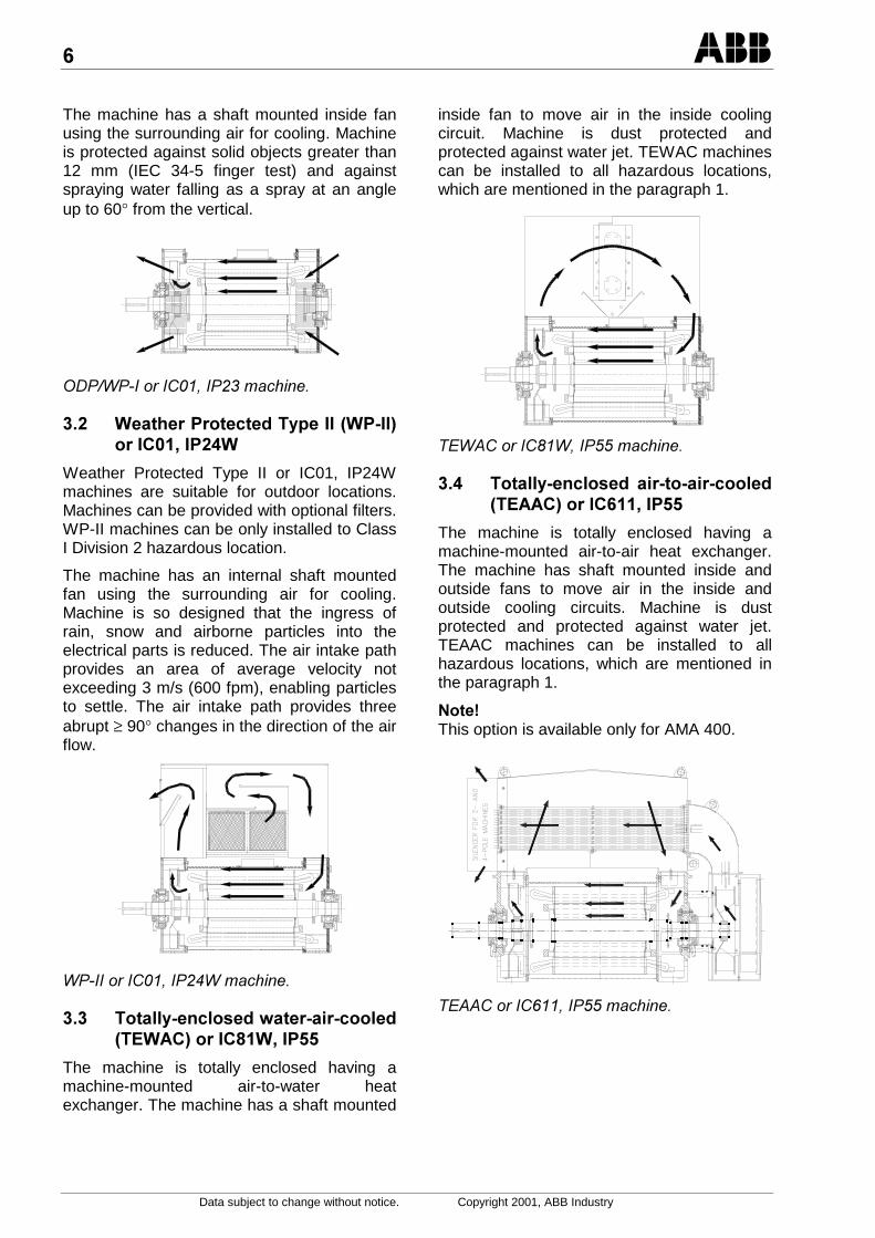
The machine has a shaft mounted inside fanusing the surrounding air for cooling. Machineis protected against solid objects greater than12 mm (IEC 34-5 finger test) and againstspraying water falling as a spray at an angleup to 60° from the vertical.
% +1 5+67.8+
Weather Protected Type II or IC01, IP24Wmachines are suitable for outdoor locations.Machines can be provided with optional filters.WP-II machines can be only installed to ClassI Division 2 hazardous location.
The machine has an internal shaft mountedfan using the surrounding air for cooling.Machine is so designed that the ingress ofrain, snow and airborne particles into theelectrical parts is reduced. The air intake pathprovides an area of average velocity notexceeding 3 m/s (600 fpm), enabling particlesto settle. The air intake path provides threeabrupt ≥ 90° changes in the direction of the airflow.
% **6* 966* 5/+.7.:+8
The machine is totally enclosed having amachine-mounted air-to-water heatexchanger. The machine has a shaft mounted
inside fan to move air in the inside coolingcircuit. Machine is dust protected andprotected against water jet. TEWAC machinescan be installed to all hazardous locations,which are mentioned in the paragraph 1.
% **6* 666* 5/.7.,8
The machine is totally enclosed having amachine-mounted air-to-air heat exchanger.The machine has shaft mounted inside andoutside fans to move air in the inside andoutside cooling circuits. Machine is dustprotected and protected against water jet.TEAAC machines can be installed to allhazardous locations, which are mentioned inthe paragraph 1.
&'This option is available only for AMA 400.
;
Data subject to change without notice. Copyright 2001, ABB Industry
%
%
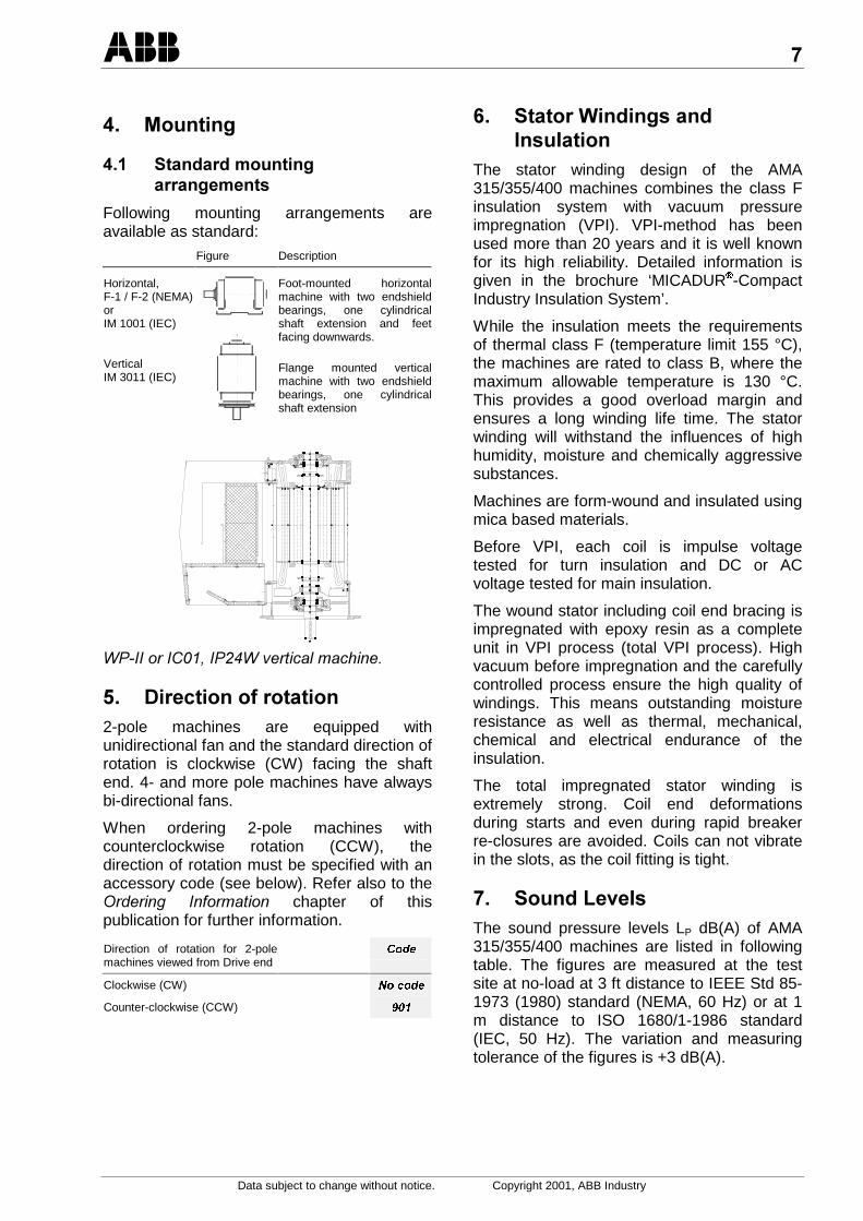
Following mounting arrangements areavailable as standard:
Figure Description
Horizontal,F-1 / F-2 (NEMA)orIM 1001 (IEC)
VerticalIM 3011 (IEC)
Foot-mounted horizontalmachine with two endshieldbearings, one cylindricalshaft extension and feetfacing downwards.
Flange mounted verticalmachine with two endshieldbearings, one cylindricalshaft extension
!"
% 2-pole machines are equipped withunidirectional fan and the standard direction ofrotation is clockwise (CW) facing the shaftend. 4- and more pole machines have alwaysbi-directional fans.
When ordering 2-pole machines withcounterclockwise rotation (CCW), thedirection of rotation must be specified with anaccessory code (see below). Refer also to the#$ %! chapter of thispublication for further information.
Direction of rotation for 2-polemachines viewed from Drive end
&RGH
1RFRGHClockwise (CW)
Counter-clockwise (CCW)
,% + *
The stator winding design of the AMA315/355/400 machines combines the class Finsulation system with vacuum pressureimpregnation (VPI). VPI-method has beenused more than 20 years and it is well knownfor its high reliability. Detailed information isgiven in the brochure ‘MICADUR-CompactIndustry Insulation System’.
While the insulation meets the requirementsof thermal class F (temperature limit 155 °C),the machines are rated to class B, where themaximum allowable temperature is 130 °C.This provides a good overload margin andensures a long winding life time. The statorwinding will withstand the influences of highhumidity, moisture and chemically aggressivesubstances.
Machines are form-wound and insulated usingmica based materials.
Before VPI, each coil is impulse voltagetested for turn insulation and DC or ACvoltage tested for main insulation.
The wound stator including coil end bracing isimpregnated with epoxy resin as a completeunit in VPI process (total VPI process). Highvacuum before impregnation and the carefullycontrolled process ensure the high quality ofwindings. This means outstanding moistureresistance as well as thermal, mechanical,chemical and electrical endurance of theinsulation.
The total impregnated stator winding isextremely strong. Coil end deformationsduring starts and even during rapid breakerre-closures are avoided. Coils can not vibratein the slots, as the coil fitting is tight.
;% <$*The sound pressure levels LP dB(A) of AMA315/355/400 machines are listed in followingtable. The figures are measured at the testsite at no-load at 3 ft distance to IEEE Std 85-1973 (1980) standard (NEMA, 60 Hz) or at 1m distance to ISO 1680/1-1986 standard(IEC, 50 Hz). The variation and measuringtolerance of the figures is +3 dB(A).
:
Data subject to change without notice. Copyright 2001, ABB Industry
ODP/WP-I or WP-II or TEWAC or TEAAC orIC01, IP23 IC01, IP24W IC81W, IP55 IC611, IP55
Poles 50 Hz60 Hz 50 Hz60 Hz 50 Hz60 Hz 50Hz 60 Hz
2 85 88 83 85 80 82 85 884 85 88 82 84 80 82 85 886 82 85 80 81 79 80 83 868(AMA400) 80 82 79 80 78 79 81 83
;% * <$*
Refer to the &'"(!)!(chapter ofthis publication for low noise WP-II (IC01,IP24W) and low noise TEAAC (IC611, IP55)machines.
:%=# $Vibration measurements taken on fullyassembled machine on no load are within thefollowing limits:Displacement 3000 rpm and above max. 0.001 in
Peak to Peak2999 rpm and below max. 0.002 in
Peak to PeakVelocity NEMA
3600 rpm and below
IEC:3000 rpm and below
max. 0.1 in/sPeak
max. 1.8 mm/sRMS
-% #
-% #°Cmin max
Water cooled machines 0 + 40
Non water cooled machineswith sleeve bearings
0 + 40
Non water cooled machineswith antifriction bearings
- 30 + 40
The machines are designed so that the statortemperature rise added to the 40 °C ambienttemperature, will not exceed the Class Btemperature rise limit.
-% *#
If ambient temperature exceeds 40 °C, thestator temperature rise must be offset byreducing the power and consequent machinelosses. A machine rated for a 40 °C ambienttemperature can be operated in a 50 °Cambient in a following way:
Rated S.F. in 40 °C Max. operating load in 50 °C
1.0 90 % of rated power
Machines applied this way will have no specialambient temperature data on the rating plate.
% *
% *
The machines are suitable for operation atsea level and up to 3 300 feet or 1000 maltitude in a maximum ambient temperature of40 °C.
% **
Machines may also be suitable for operationat higher elevations with derating of ambienttemperature or service factor. As a guide,machine temperature rise increases 1 % forevery 330 feet above 3 300 feet or for every100 m above 1000 m, which means:Rated S.F.in 40 °C
Ambienttemperature
Max. altitude withS.F 1.0
1.0 30 °C 6600 Ft. or 2000 m
1.0 20 °C 9900 Ft. or 3000 m
Machines applied this way will have no specialaltitude or temperature data on the ratingplate.
% 0 1AMA 315/355/400 machines have a fabricatedrotor cage. It is either copper or aluminumalloy (2-pole machines with aluminum). Thecopper bars are brazed to the copper shortcircuit end rings. The bars of the aluminumcage are made of extruded rod and arecontinuous welded in an automatic machine tothe aluminum short circuit end rings. The barsare mechanically locked into the slots byswedging. The rotors of hazardous locationmachines are additionally resin treated toprevent sparking.
The rotor is balanced with a half key, which isindicated with letter H stamped on the shaftend.
The standard shaft material is hot rolledASTM A 572-81:Grade 50 or St52-3 steel.The rotor core is shrink fitted to the shaft.
% .*Machines are normally designed for directconnection with flexible coupling. In case ofsleeve bearings the coupling must be axiallylimiting type. The rotor of the machine isbalanced with a half key, which must be notedwhen selecting and balancing the coupling.
-
Data subject to change without notice. Copyright 2001, ABB Industry
% !The horizontally mounted machines areprovided either with antifriction bearings orwith sleeve bearings, the vertically mountedmachines are provided only with antifrictionbearings.
The bearing arrangements are specified in themachine type designation.
% # 1>** 1
.1
• Deep groove ball bearings in both ends ofthe machine
• Minimum lifetime (L10h) is 100 000 hours
• Regreasable bearings
• Labyrinth seal without any wearing parts
• Axially free NDE (opposite drive end)bearing to allow thermal elongation
• Axially free bearing is spring loaded toreduce noise and vibration
• The complete bearing type designations areindicated on lubrication plate
• Relubrication data is indicated on lubricationplate
• SPM-nipples (Shock Pulse Measuring) forbearing condition monitoring as standard onboth ends of the machine
• Tested for IP56 protection (excluding opendeck marine applications)
• Factory grease ESSO Unirex N2Standard ball bearings for horizontal mountingmachines are listed in the following table:
AMA type Poles DE bearing NDE bearing
315 all 6317M/C3 6317M/C3
355 2 6317M/C3 6317M/C3
4 or more 6319/C3 6319/C3
400 2 6317M/C3 6317M/C3
4 or more 6324/C3 6324/C3
DE = Drive End, NDE = Non Drive End
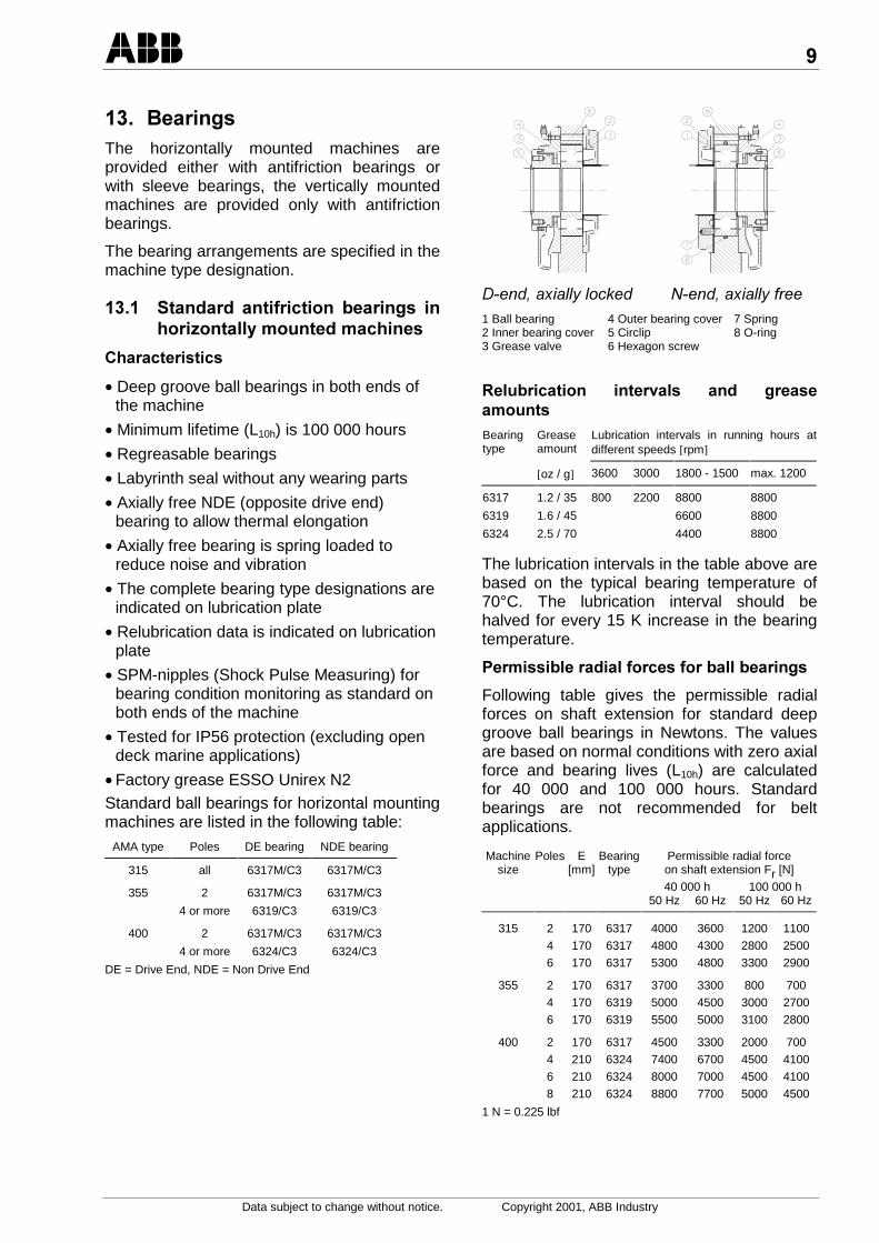
#*""+",# -#*""+%1 Ball bearing 4 Outer bearing cover 7 Spring2 Inner bearing cover 5 Circlip 8 O-ring3 Grease valve 6 Hexagon screw
0*# $*
Bearingtype
Greaseamount
Lubrication intervals in running hours atdifferent speeds [rpm]
[oz / g] 3600 3000 1800 - 1500 max. 1200
6317 1.2 / 35 800 2200 8800 8800
6319 1.6 / 45 6600 8800
6324 2.5 / 70 4400 8800
The lubrication intervals in the table above arebased on the typical bearing temperature of70°C. The lubrication interval should behalved for every 15 K increase in the bearingtemperature.
#* *#**#
Following table gives the permissible radialforces on shaft extension for standard deepgroove ball bearings in Newtons. The valuesare based on normal conditions with zero axialforce and bearing lives (L10h) are calculatedfor 40 000 and 100 000 hours. Standardbearings are not recommended for beltapplications.
Machinesize
Poles E[mm]
Bearingtype
Permissible radial forceon shaft extension Fr [N]
40 000 h 100 000 h50 Hz 60 Hz 50 Hz 60 Hz
315 2 170 6317 4000 3600 1200 1100
4 170 6317 4800 4300 2800 2500
6 170 6317 5300 4800 3300 2900
355 2 170 6317 3700 3300 800 700
4 170 6319 5000 4500 3000 2700
6 170 6319 5500 5000 3100 2800
400 2 170 6317 4500 3300 2000 700
4 210 6324 7400 6700 4500 4100
6 210 6324 8000 7000 4500 4100
8 210 6324 8800 7700 5000 4500
1 N = 0.225 lbf

Data subject to change without notice. Copyright 2001, ABB Industry
#*?*#**#
Following table gives the permissible axialforces for standard bearings in Newtons,assuming zero radial force. The values arebased on normal conditions and calculatedbearing lives (L10h) 40 000 h and 100 000 h.FaÍ is the force acting towards the machine(D-end) and FaÌ is the force acting outwardsthe machine (D-end).Machine Poles Bearing Permissible axial force Fa [N]
Size type 40 000 h 100 000 hFaÍ FaÌ FaÍ FaÌ
315 2 6317 1800 4800 600 3600
4 6317 2800 5800 1300 4300
6 6317 3500 6500 1700 4700
355 2 6317 1700 4700 500 3500
4 6319 3200 6200 1500 4500
6 6319 3900 6900 1800 4800
400 2 6317 1600 4600 500 3500
4 6324 4400 8400 2100 6100
6 6324 5200 9200 2600 6600
8 6324 6100 10100 3100 7100
The values are for 60 Hz, they can be added by 10 % for 50 Hzmachines. 1 N = 0.225 lbf
% # $** 1
.1
• Deep groove ball bearing in drive end andangular contact ball bearing in non-drive endof the machine
• Minimum lifetime (L10h) is 100 000 hours
• Regreasable bearings
• Labyrinth seal without any wearing parts
• Axially free DE (drive end) bearing to allowthermal elongation
• Axially free bearing is spring loaded toreduce noise and vibration
• The complete bearing type designations areindicated on lubrication plate
• Relubrication data is indicated on lubricationplate
• SPM-nipples (Shock Pulse Measuring) forbearing condition monitoring as standard onboth ends of the machine
• Tested for IP56 protection (excluding opendeck marine applications)
• Factory grease ESSO Unirex N2Standard ball bearings for vertical mountingmachines are listed in the following table:
AMA type Poles DE bearing NDE bearing
315 4 or more 6317/C3 7317
355 4 or more 6319/C3 7319
400 4 or more 6324/C3 7324
DE = Drive End, NDE = Non Drive End
-#*""+",# #*""+%1 Ball bearing 4 Outer bearing cover 7 Spring2 Inner bearing cover 5 Circlip 8 O-ring3 Grease valve 6 Hexagon screw
0*# $*
Bearingtype
Greaseamount
Lubrication intervals in running hours atdifferent speeds [rpm]
[oz / g] 1500-1800 1000 – 1200 max. 900
6317 1.2 / 35 4400 4400
6319 1.6 / 45 3300 4400
6324 2.5 / 70 2200 4400 4400
7317 1.2 / 35 4400 4400
7319 1.6 / 45 3300 4400
7324 2.5 / 70 2200 4400 4400
The lubrication intervals in the table are basedon the typical bearing temperature of 70°C.The lubrication interval should be halved forevery 15 K increase in the bearingtemperature.
#* *#**#
Following table gives the permissible radialforces on shaft extension for a standard deepgroove ball bearings in Newtons. The valuesare based on normal conditions with zero axialforce and bearing lives (L10h) are calculatedfor 40 000 and 100 000 hours. Standardbearings are not recommended for beltapplications.

Data subject to change without notice. Copyright 2001, ABB Industry
Machinesize
Poles E[mm]
Bearingtype
Permissible radial forceon shaft extension Fr [N]
40 000 h 100 000 h50 Hz 60 Hz 50 Hz 60 Hz
315 4 170 6317 4800 4300 2800 2500
6 170 6317 5300 4800 3300 2900
355 4 170 6319 5000 4500 3000 2700
6 170 6319 5500 5000 3100 2800
400 4 210 6324 7400 6700 4500 4100
6 210 6324 8000 7000 4500 4100
8 210 6324 8800 7700 5000 4500
1 N = 0.225 lbf
#*?*#**#
&' Only downward forces are allowed
Following table gives the permissible axialforces downwards for standard bearings inNewtons, assuming zero radial force. Thevalues are based on normal conditions andcalculated bearing lives (L10h) 40 000 h and100 000 h. Values are calculated withmaximum rotor weight.Machine Poles Bearing Permissible axial force Fa [N]
Size type 40 000 h 100 000 hFaÏ FaÏ
315 4 7317 9 000 5 000
6 7317 11 000 6 000
355 4 7319 10 000 5 000
6 7319 11 000 6 000
400 4 7324 13 000 7 000
6 7324 16 000 9 000
8 7324 18 000 10 000
The values are for 60 Hz, they can be added by 10 % for 50 Hzmachines. 1 N = 0.225 lbf
% *$ # 1>** 1
.1
• Sleeve bearings in both ends of the machine
• Rigid cast iron bearing housing
• The shell consists of a steel body, which islined with white metal
• Self-lubricating = the bearing housing isfilled with lubricating oil and the bearings arelubricated by oil ring
• The standard end float of the sleevebearings is 1/2” (±1/4”) or 12 mm (±6 mm)
• The DE sleeve bearing is axially locatingone
• The complete type designation is stampedon the lubrication plate
• Lubrication data is indicated on lubricationplate
• IP55 protection
!>
AMA type Poles DE bearing NDE bearing315 all ZMNLB 7-75 ZMNLB 7-75355 all ZMNLB 7-75 ZMNLB 7-75400 2 EFZLB 9-80 EFZLQ 9-80
4 or more EFZLB 9-100 EFZLQ 9-100ZM = center flange mounted bearingEF = side flange mounted bearing
! %"$ )!# (" .$ !+'/0
&#%"$)!#(" .$!+'1
• Mineral oils are used for lubrication of sleevebearings. The oil must have a viscosity valueas defined in SSU or ISO 3448 class. Theexact viscosity value is stated on lubricationplate.
• There is an oil level sight glass on the sideof the bearing for checking of the oil level.
• Oil change after 8800 operating hours.Shorter intervals are required in the case offrequent starting and stopping, high oiltemperatures or excessive contaminationthrough external influences.
Rotation speed and oil viscosity grade:
Rotation speed [rpm] SSU viscositygrade number
ISO viscosity gradenumber
Below 1200 315 SSU/100 °F ISO VG 681200 – 1800 214 SSU/100 °F ISO VG 46Above 1800 150 SSU/100 °F ISO VG 32
Data subject to change without notice. Copyright 2001, ABB Industry
#**$#
Standard sleeve bearings do not withstandexternal loads. The driven equipment mustcarry all external loads. End float must belimited with a limiting type of coupling.
% * # #
Refer to the '!" ((( #1!)( chapter of this publication forbearing temperature control.
Refer to the &'"(!)!(chapter ofthis publication for other bearings or bearingaccessories.
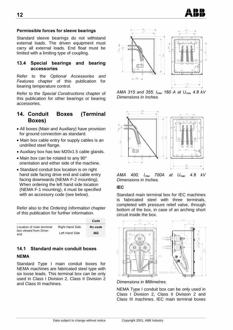
% . !? 5*!?7
• All boxes (Main and Auxiliary) have provisionfor ground connection as standard.
• Main box cable entry for supply cables is anundrilled steel flange.
• Auxiliary box has two M20x1.5 cable glands.
• Main box can be rotated to any 90°orientation and either side of the machine.
• Standard conduit box location is on righthand side facing drive end and cable entryfacing downwards (NEMA F-2 mounting).When ordering the left hand side location(NEMA F-1 mounting), it must be specifiedwith an accessory code (see below).
Refer also to the #$%!chapterof this publication for further information.
&RGH
Right Hand Side 1RFRGHLocation of main terminalbox viewed from Drive-end Left Hand Side
% #?
&/
Standard Type I main conduit boxes forNEMA machines are fabricated steel type withsix loose leads. This terminal box can be onlyused in Class I Division 2, Class II Division 2and Class III machines.
0 #2 PD[ !3PD[ ,4(((
0 2 PD[ 5 ! 3PD[ ,4(((
/.
Standard main terminal box for IEC machinesis fabricated steel with three terminals,completed with pressure relief valve, throughbottom of the box, in case of an arching shortcircuit inside the box.
((0""!(
NEMA Type I conduit box can be only used inClass I Division 2, Class II Division 2 andClass III machines. IEC main terminal boxes

Data subject to change without notice. Copyright 2001, ABB Industry
can be used as well in all specified hazardouslocations (see page 2).
% ?* #?
(((60""!(.,!(7
% * #?
Refer to the &'"(!)!(chapter ofthis publication for other conduit box (terminalbox) arrangements and accessories.
% .
% 57
The surface treatment of the machines isbased on epoxy paint system suitableespecially for urban and industrialatmospheres with moderate corrosive attack(ISO 12944–2, C2 and C3 without direct UV-radiation). Total dry film thickness of 120 µmis recommended if the atmospheric stress islow (C2).
Water-borne paints are used always whenpossible. The pre-treatment and painting ofthe machines are done according torespective machine surface materials.
The color of the finish paint is as standardblue Munsell 8B 4.5/3.25. The machines areprimered inside (shields, frame etc.) asstandard.
All materials, like castings, sheet steel,screws, washers etc., are treated with amethod appropriate to the material for reliableanti-corrosion protection under severeenvironmental conditions.
Bolts and nuts are zinc plated, or equivalent,hex head metric series.
% *
Refer to the &'"(!)!(chapter ofthis publication for other paintings or finishingcolors.
,%
,%
The following accessories are included asstandard to all machines:
• 6 pcs of Pt-100 RTDs in stator winding, as4-wire connection to a separate auxiliaryterminal box. They are also approved forhazardous locations.
• SPM-nipples, one per antifriction bearing
• 4 pcs of jacking screws in horizontalmachines
• Stainless steel rating plates
• 4 pcs of lifting lugs
• 2 pcs of dowel holes in horizontal machines
,% *
Refer to the '!" ((( #1!)( chapter of this publication for otheraccessories.
;% @
;% @
When AMA machine will be delivered withtruck or train, it does not need any specialpacking. The machine is fixed with bolts towooden pallet and covered with plastic whenneeded. The lifting can be done by crane fromthe lifting eyes located on the frame of themachine.
;% *@
Refer to the &'"(!)!(chapter ofthis publication for other packing possibilities.
:%
:% 0
All AMA 315/355/400 machines are tested tothe following routine test program:
• Visual inspection
• Air gap measurement
• Insulation resistance measurement
• Resistance measurement at the ambienttemperature
• Terminal markings and direction of rotation
• Axial play, only for machines with sleevebearings

Data subject to change without notice. Copyright 2001, ABB Industry
• Vibration measurement
• No load point
• Short circuit point
• High voltage test
• Insulation resistance measurement
:% *
Refer to the '!" ((( #1!)( chapter of this publication for othertests.
-%
-%
Following documents and manuals aresupplied with each order:
• Performance data of machine
• Torque and current vs. speed curve
• Certified outline drawing
• Main connection diagram including diagramfor control equipment
• Connection
• Instruction for Installation, Maintenance andService
• Routine Test Report
-% *
Refer to the &'"(!)!(chapter ofthis publication for other documentation.

Data subject to change without notice. Copyright 2001, ABB Industry
.)/0!% * 3
If machine described in 8( 0('! chapter of this publication doesnot meet the requirements, the followingoptional accessories and features areavailable.
% .* $/A
% *
2 pcs of Pt-100 RTDs in bearings (1 pcs /bearing), as 4-wire connection to an auxiliaryterminal box (where stator RTDs areconnected).
Location Sensor &RGH +D]/RF&RGH
Bearings Pt-100, 4-wire
Refer to the &'"(!)!(chapter ofthis publication for other temperature controlalternatives.
% 1
250 W space heater for normal environmentwith a separate terminal box. The whole unitcan be changed or retrofitted withoutdismantling the machine.
Supply voltage &RGH +D]/RF&RGH
110 - 120 V
220 - 250 V
380 - 440 V
480 - 500 V
Refer to the &'"(!)!(chapter ofthis publication for other space heateralternatives.
% 3* +1 15+6+7
Panel type, all metal (galvanized or stainlesssteel) and washable filters can be applied tonormal industrial applications. Whole unit canbe changed or retrofitted even when themachine is in operation.
&RGH
Galvanized
StainlessSteel
% * 91 *
Adjustable, single pole changeover contactdifferential pressure switch for conditionmonitoring of filters in WP-II or IP24Wmachines. Maximum load of the switch is 277VAC / 10 A / 300 VA.
&RGH
The Differential Pressure Switch can be alsoused in hazardous location, but it must beconnected to intrinsic safety circuit.
% <@ 1?15/+..:+7
Leakage detector with rated voltage 8 VDC(operating voltage 5 to 60 VDC) for conditionmonitoring of air-to-water heat exchangers inTEWAC or IC81W machines.
&RGH
The Leakage Detector can be also used inhazardous location, but it must be connectedto intrinsic safety circuit.
%
%
Following tests are added to the Routine Testprogram in Chapter 18.1. for the Type Tests:
• Inertia measurement
• Heat run test
• No load curve and determination ofefficiency
• Starting current
&RGH
Type Test
Witnessed Type Test
,
Data subject to change without notice. Copyright 2001, ABB Industry
% 3 /A
% 3
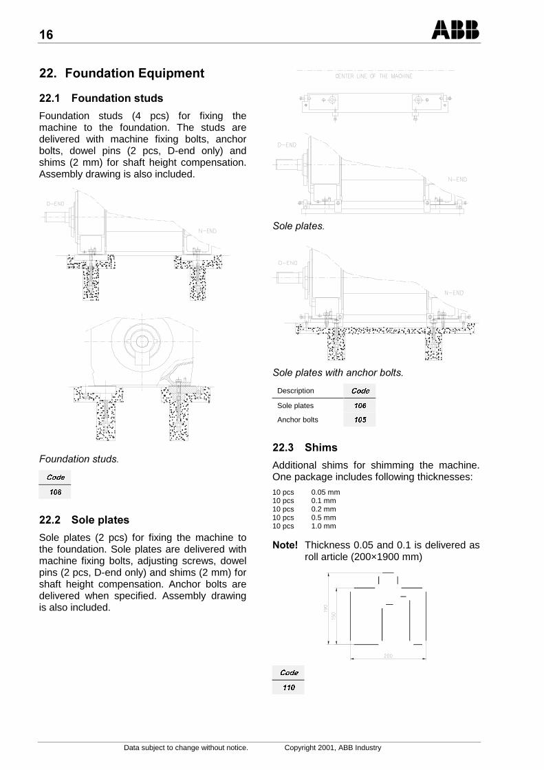
Foundation studs (4 pcs) for fixing themachine to the foundation. The studs aredelivered with machine fixing bolts, anchorbolts, dowel pins (2 pcs, D-end only) andshims (2 mm) for shaft height compensation.Assembly drawing is also included.
1)#!(!)#(
&RGH
% **
Sole plates (2 pcs) for fixing the machine tothe foundation. Sole plates are delivered withmachine fixing bolts, adjusting screws, dowelpins (2 pcs, D-end only) and shims (2 mm) forshaft height compensation. Anchor bolts aredelivered when specified. Assembly drawingis also included.
&"'"!(
&"'"!(9!."!(
Description &RGH
Sole plates
Anchor bolts
% 1
Additional shims for shimming the machine.One package includes following thicknesses:10 pcs 0.05 mm10 pcs 0.1 mm10 pcs 0.2 mm10 pcs 0.5 mm10 pcs 1.0 mm
&' Thickness 0.05 and 0.1 is delivered asroll article (200×1900 mm)
&RGH
;
Data subject to change without notice. Copyright 2001, ABB Industry
.)/0.% *.
If machine described in 8( 0('!chapter and '!"(((# 1!)( described in Chapter B of thispublication does not meet the requirements,following special constructions are available.
% .* $/A
% *
As a standard there are 6 pcs of Pt-100 RTDsin stator winding as 4-wire connection to aseparate auxiliary terminal box.
On separate request following alternatives arealso available:
• 6 pcs of Cu-10 RTDs instead of standard Pt-100 RTDs, as 4-wire connection to aseparate auxiliary terminal box.Location Sensor &RGH
Stator Cu-10, 4-wire
Cu-10 RTDs can be also used in hazardouslocation, but they must be connected tointrinsic safety circuit
!
&' Totally 2 alternatives can be chosenfor bearings.
• 2 pcs of Cu-10 RTDs (1 pcs/bearing), as 4-wire connection to an auxiliary terminal box(where stator RTDs are connected).
• 2 pcs of thermocouples (1 pcs/bearing)wired to an auxiliary terminal box (wherestator RTDs are connected).
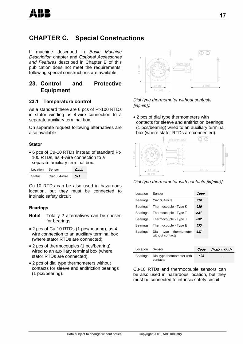
• 2 pcs of dial type thermometers withoutcontacts for sleeve and antifriction bearings(1 pcs/bearing).
"!+'!!9!)!!!([[]]
• 2 pcs of dial type thermometers withcontacts for sleeve and antifriction bearings(1 pcs/bearing) wired to an auxiliary terminalbox (where stator RTDs are connected).
"!+'!!9!!!([[]]
Location Sensor &RGH
Bearings Cu-10, 4-wire
Bearings Thermocouple - Type K
Bearings Thermocouple - Type T
Bearings Thermocouple - Type J
Bearings Thermocouple - Type E
Bearings Dial type thermometerwithout contacts
Location Sensor &RGH +D]/RF&RGH
Bearings Dial type thermometer withcontacts
Cu-10 RTDs and thermocouple sensors canbe also used in hazardous location, but theymust be connected to intrinsic safety circuit

:
Data subject to change without notice. Copyright 2001, ABB Industry
.*
Following alternatives are available for totallyenclosed machines:
• 2 pcs of Pt-100 RTDs (one in each end) as4-wire connection to an auxiliary terminalbox (where stator RTDs are connected).
• 2 pcs of Cu-10 RTDs (one in each end) as4-wire connection to an auxiliary terminalbox (where stator RTDs are connected).
• 2 pcs of thermocouples (one in each end)connected to an auxiliary terminal box(where stator RTDs are connected).
• 2 pcs of dial type thermometers withoutcontacts (one in each end).
"!+'!!9!)!!!(%"$6677
• 2 pcs of dial type thermometer with contacts(one in each end) wired to an auxiliaryterminal box (where stator RTDs areconnected). See figure “Dial typethermometer with contacts” (bearings).
Location Sensor &RGH +D]/RF&RGH
Cooling air Pt-100, 4-wire
Location Sensor &RGH
Cooling air Cu-10, 4-wire
Cooling air Thermocouple - Type K
Cooling air Thermocouple - Type T
Cooling air Thermocouple - Type J
Cooling air Thermocouple - Type E
Cooling air Dial type thermometerwithout contacts
Location Sensor &RGH +D]/RF&RGH
Cooling air Dial type thermometerwith contacts
Cu-10 RTDs and Thermocouples can be alsoused in hazardous location, but they must beconnected to intrinsic safety circuit.
% 0 1*
Temperature coefficient of RTDs depends onresistor material and dimensioning. Todetermine the exact temperature function ofresistance, a temperature transmitter can beused. The measuring range is 0 - 200°C withthe output of 4 - 20 mA. The standardtemperature transmitter unit covers thetransmitters for three temperature sensors ofstator winding and one temperature sensorper bearing. Transmitters are mounted inauxiliary terminal box.
&RGH +D]/RF&RGH
Transmitters for hazardous location must beconnected to intrinsic safety circuit.
% =#
Following equipment is available for vibrationmonitoring of AMA 315/355/400 machines.
=#91 * ,,66:50# 197
The Vibraswitch Malfunction Detector is anacceleration sensitive instrument thatmeasures the total destructive acceleratoryforces acting on rotating and reciprocatingmachinery. The detector is mounted inhorizontal position on the D-end housing ofthe horizontal machine and in horizontalposition on the ND-end housing of the verticalmachine. The detector is wired to auxiliaryterminal box.
-
Data subject to change without notice. Copyright 2001, ABB Industry
1* B
Contact rating: 5 Amps at 117 VAC, 50/60 HzCoil power: 14 W maximumMeasurement range: 0 to 4.5 g from 0 to 300 Hz (18,000 RPM)Switch contacts: SPDT Single pole, double throw load
contactsRemote option reset: 117 volt AC reset coil voltageMounting locations: Nonhazardous, outdoors, unprotected,
meets NEMA 1 thru 5 and 12classification
Accuracy: ± 5 % of full range from 30 to 300 HzSetpoint Adjustment: 1 turn per g
Measurementpoint
&RGH +D]/RF&RGH
D-end, horizontaldirection
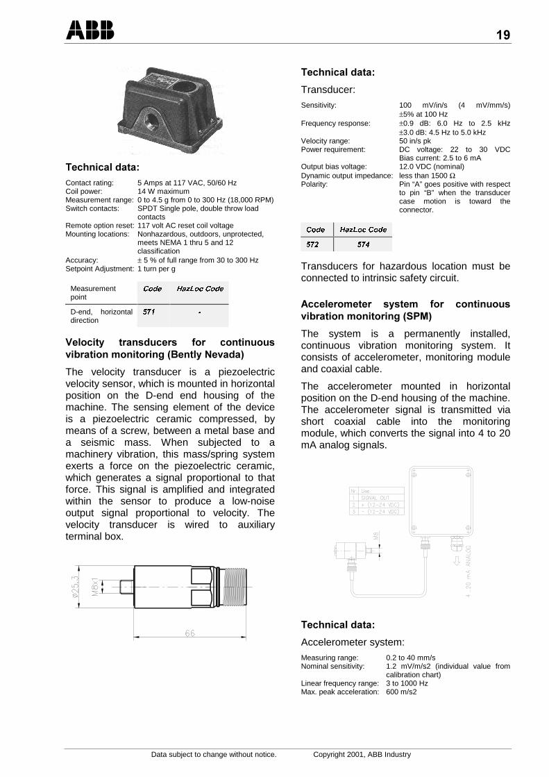
=* $#5!*&$ 7
The velocity transducer is a piezoelectricvelocity sensor, which is mounted in horizontalposition on the D-end end housing of themachine. The sensing element of the deviceis a piezoelectric ceramic compressed, bymeans of a screw, between a metal base anda seismic mass. When subjected to amachinery vibration, this mass/spring systemexerts a force on the piezoelectric ceramic,which generates a signal proportional to thatforce. This signal is amplified and integratedwithin the sensor to produce a low-noiseoutput signal proportional to velocity. Thevelocity transducer is wired to auxiliaryterminal box.
1* B
Transducer:Sensitivity: 100 mV/in/s (4 mV/mm/s)
±5% at 100 HzFrequency response: ±0.9 dB: 6.0 Hz to 2.5 kHz
±3.0 dB: 4.5 Hz to 5.0 kHzVelocity range: 50 in/s pkPower requirement: DC voltage: 22 to 30 VDC
Bias current: 2.5 to 6 mAOutput bias voltage: 12.0 VDC (nominal)Dynamic output impedance: less than 1500 ΩPolarity: Pin “A” goes positive with respect
to pin “B” when the transducercase motion is toward theconnector.
&RGH +D]/RF&RGH
Transducers for hazardous location must beconnected to intrinsic safety circuit.
* $#5 7
The system is a permanently installed,continuous vibration monitoring system. Itconsists of accelerometer, monitoring moduleand coaxial cable.
The accelerometer mounted in horizontalposition on the D-end housing of the machine.The accelerometer signal is transmitted viashort coaxial cable into the monitoringmodule, which converts the signal into 4 to 20mA analog signals.
1* B
Accelerometer system:Measuring range: 0.2 to 40 mm/sNominal sensitivity: 1.2 mV/m/s2 (individual value from
calibration chart)Linear frequency range: 3 to 1000 HzMax. peak acceleration: 600 m/s2

Data subject to change without notice. Copyright 2001, ABB Industry
Vibration monitoring module:Channels: 1 pcsMeasuring range 1: 0 to 5 mm/s (0 to 0.19 in/s)Measuring range 2: 0 to 10 mm/s (0 to 0.39 in/s)Measuring range 3: 0 to 20 mm/s (0 to 0.78 in/s)Measuring range 4: 0 to 40 mm/s (0 to 1.57 in/s)Frequency range: 10 to 1000 HzMeasuring time: appr. 1 sAnalog output: 4 to 20 mAFault indication: <1 mA out = interrupted transducer linePower supply: 12 to 24 VDCAmbient temperature:0 to +55 °C
&RGH +D]/RF&RGH
% 1
2x100 W low surface temperature (max. 170°C) space heaters with a separate terminalbox. The whole unit can be changed orretrofitted without dismantling the machine.
Supply voltage &RGH
110 V
220 V
% */
Bi-directional digital hollow shaft pulseencoder with operating voltage 9 to 30 V.
Pulse rate &RGH +D]/RF&RGH
1024 ppr
2048 ppr
% !4!
% !1*
There are three basic types of bearinghousing seals:
• rubbing seals
• non-rubbing seals
• combined sealsGrease lubricated antifriction bearings of AMA315/355/400 machines have a non-rubbinglabyrinth sealing as a standard sealingmethod. Advantage of labyrinth sealing is thatit does not have any wearing parts. Thestandard construction has been tested inhorizontal position for IP56.
&0 /<
Besides standard labyrinth sealing alsoINPRO/SEAL bearing isolators areavailable. INPRO/SEAL bearing isolator is atwo-part dynamic seal (stator press fitted intothe bearing housing and rotor attached to theshaft). The rotor and stator form a non-contact, compound labyrinth. Degree ofprotection is IP56.
1 Grease valve2 Lid for INPRO/SEAL3 INPRO/SEAL bearing isolator4 Hexagon screw
INPRO/SEAL is a trademark of INPRO COMPANIES, INC.
&RGH
.&/C/ /<
Taconite type seal is a combination of rubbingand non-rubbing seals and therefore it is notrecommended for 2-pole machines due tohigh peripheral speeds. Degree of protectionis IP55.
1 Grease valve 4 V-ring2 Inner labyrinth half 5 Set screw3 Outer labyrinth half 6 Hexagon screw
&RGH
% !*
In case of e.g. converter supply bearinginsulation can be provided to both ends (driveand non drive end) of the machine. Usuallyonly the non drive end bearing is insulated. Ifdrive-end bearing is also insulated it is
Data subject to change without notice. Copyright 2001, ABB Industry
possible to measure potential differencebetween rotor and stator (e.g. for bearinginsulation control without disassembling themachine). When both ends are insulated, D-end insulation is short circuited with a cableduring normal operation.
Item Use &RGH
Insulated ND-end To prevent bearingcurrents
Insulated D-endand ND-end
To check thecondition of bearinginsulation
% 2#?? 9
Grease lubricated bearings are provided withgrease valves. Relubrication is to beperformed while the machine is running. Theexcess and waste grease is removed throughthe relief valve in the bottom of the outerbearing cover. If required grease lubricatedbearings can be equipped with a grease box.
&RGH
% . *$* * *6*# *$#
The oiler is designed to maintain the proper oillevel at all times. The lubricator reactsautomatically as the oil level lowers in thebearing and replaces the amount of oil usedwith a fresh supply until the original oil level isagain attained. Reservoir material is glass andoil capacity is 0.12 litres.
&RGH
% . !? 5*!?7
Besides standard main conduit boxesfollowing alternatives are also available.
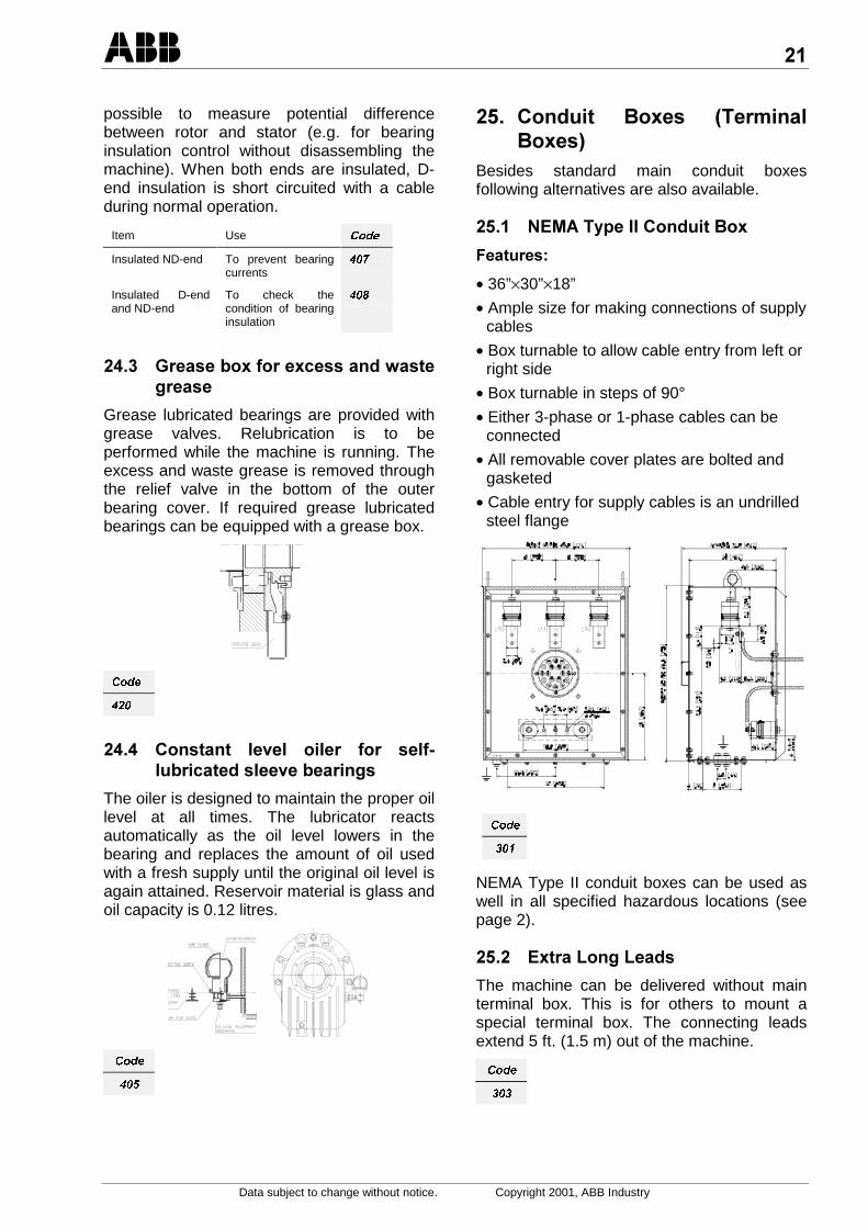
% &/. !?
3B
• 36”×30”×18”
• Ample size for making connections of supplycables
• Box turnable to allow cable entry from left orright side
• Box turnable in steps of 90°
• Either 3-phase or 1-phase cables can beconnected
• All removable cover plates are bolted andgasketed
• Cable entry for supply cables is an undrilledsteel flange
&RGH
NEMA Type II conduit boxes can be used aswell in all specified hazardous locations (seepage 2).
% /?<<
The machine can be delivered without mainterminal box. This is for others to mount aspecial terminal box. The connecting leadsextend 5 ft. (1.5 m) out of the machine.
&RGH
Data subject to change without notice. Copyright 2001, ABB Industry
,%
,% **1
The machine is painted according to standardpainting procedure but with special colorshade.
,% *57
This UV-resistant surface treatment is basedon epoxy-polyurethane paint system suitablefor moderate outdoor conditions in city-, sea-,industrial climates with direct UV radiation(ISO 12944-2, C3). The pretreatment andpainting of the machines are done accordingto respective machine surface materials. Thecolour shade is standard.
,% *57
The surface treatment of the machines isbased on epoxy paint system suitable forespecially straining outdoor conditions in city-,sea-, industrial climates (ISO 12944-2, C4).Suitable for chemical industry with highhumidity and ship machinery on deck. Thepre-treatment and painting of the machinesare done according to respective machinesurface materials. The colour shade isstandard.
&RGH
Special colour shade
Special painting (Paint system 2)
Special painting (Paint system 3)
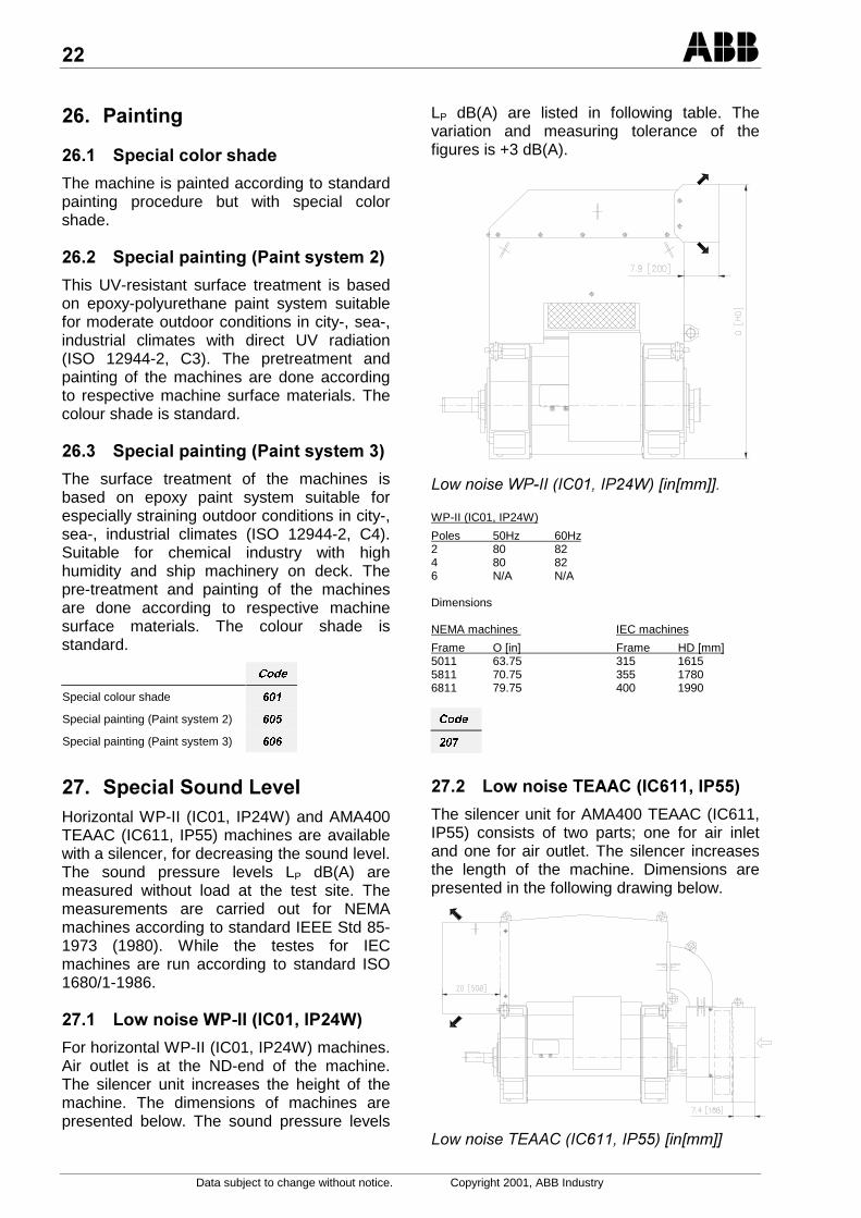
;% * <$*Horizontal WP-II (IC01, IP24W) and AMA400TEAAC (IC611, IP55) machines are availablewith a silencer, for decreasing the sound level.The sound pressure levels LP dB(A) aremeasured without load at the test site. Themeasurements are carried out for NEMAmachines according to standard IEEE Std 85-1973 (1980). While the testes for IECmachines are run according to standard ISO1680/1-1986.
;% <9+65.8+7
For horizontal WP-II (IC01, IP24W) machines.Air outlet is at the ND-end of the machine.The silencer unit increases the height of themachine. The dimensions of machines arepresented below. The sound pressure levels
LP dB(A) are listed in following table. Thevariation and measuring tolerance of thefigures is +3 dB(A).
:9(; <6677
WP-II (IC01, IP24W)
Poles 50Hz 60Hz2 80 824 80 826 N/A N/A
Dimensions
NEMA machines IEC machines
Frame O [in] Frame HD [mm]5011 63.75 315 16155811 70.75 355 17806811 79.75 400 1990
&RGH
;% <9/.5.,87
The silencer unit for AMA400 TEAAC (IC611,IP55) consists of two parts; one for air inletand one for air outlet. The silencer increasesthe length of the machine. Dimensions arepresented in the following drawing below.
:9(; <6677

Data subject to change without notice. Copyright 2001, ABB Industry
The sound pressure levels LP dB(A) are listedin following table.
TEAAC orIC611, IP55
Poles 50Hz 60Hz2 81 844 80 836 80 83
&RGH
:% @The AMA machines are packed in a containeror a wooden box for overseas transportation.This ensures good protection against water,salt spray, moisture, rust and vibration duringthe loading, sea transportation and unloadingof the machine. The dimensions and otherrequirements of the box are stated for eachmachine separately.
Spare parts and accessories are normallypacked in the same box with the machine.
Sea transportation package is stronglyrecommended if the machine will be stored forlonger time.
Addresses, packing numbers and shippingmarks as well as weights and dimensions arepainted on two sides of the box. All necessarycare, centre and sling marks are provided.
Packing lists are placed outside the box undera metal plate.
The lifting should be done by using a forklift ora crane due to rigid construction of the box.
&RGH
Seaworthy Packing
Seaworthy Packing,impregnated wood
-% Following additional documents are alsoavailable:
Item &RGH
Rotor drawing for torsional analysis
Sectional drawing of the machine
Dimension drawing of main conduit box
Dimension drawing of auxiliary conduit box

Data subject to change without notice. Copyright 2001, ABB Industry
.)/0% 9
% &/1Page
NEMA WP-I/ODP with antifriction bearings .................. 25
NEMA WP-I/ODP with sleeve bearings ........................ 26
NEMA WP-II with antifriction bearings.......................... 27
NEMA WP-II with sleeve bearings................................ 28
NEMA TEWAC with antifriction bearings ...................... 29
NEMA TEWAC with sleeve bearings ............................ 30
NEMA TEAAC with antifriction bearings ....................... 31
NEMA TEAAC with sleeve bearings ............................. 32
% /.1
Horizontal Machines:
IEC IC01, IP23 with antifriction bearings, IM 1001........ 33
IEC IC01, IP23 with sleeve bearings, IM 1001.............. 34
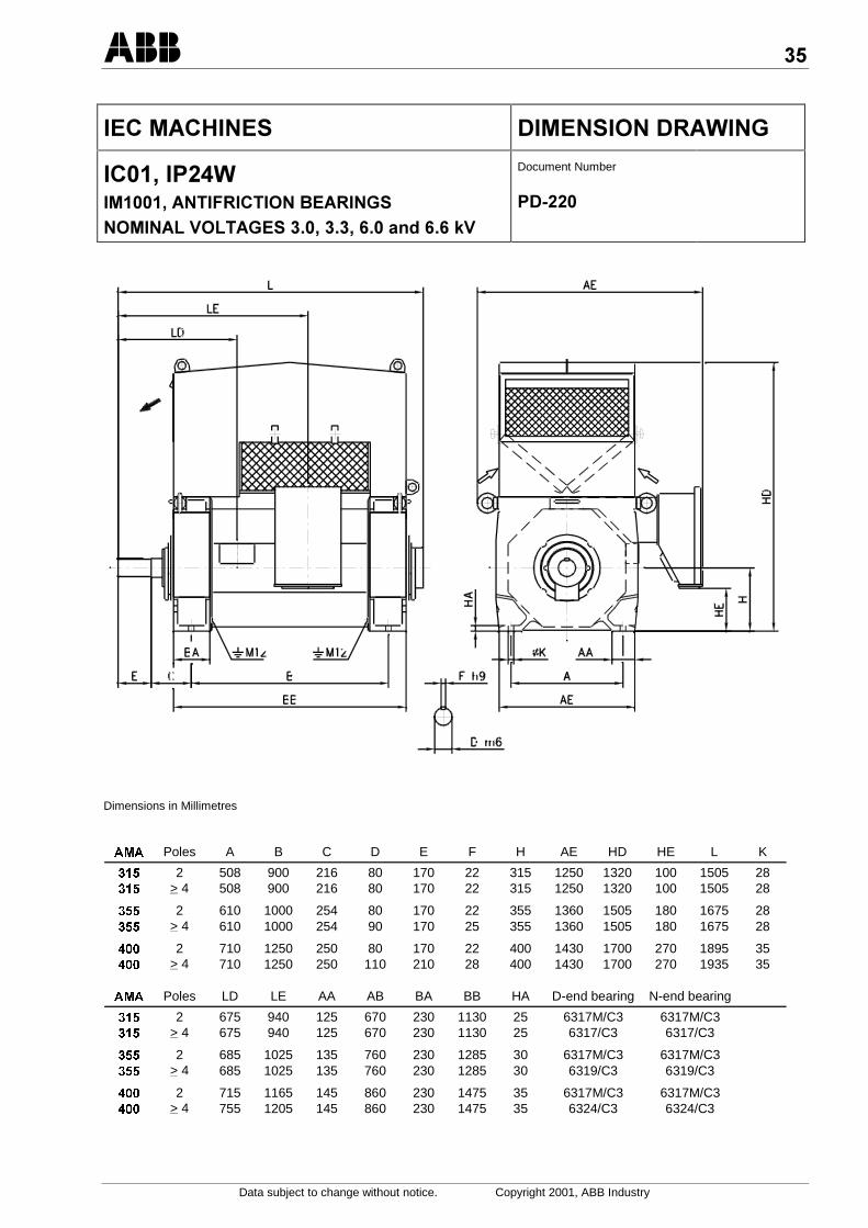
IEC IC01, IP24W with antifriction bearings, IM 1001 .... 35
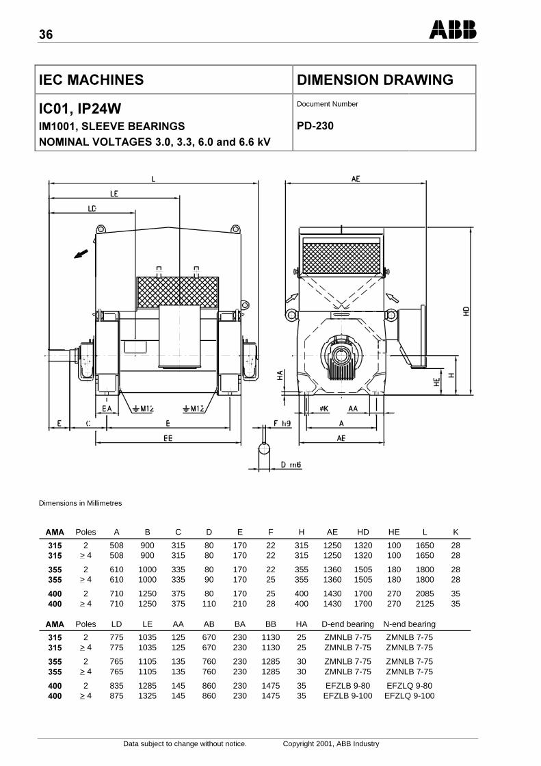
IEC IC01, IP24W with sleeve bearings, IM 1001 .......... 36
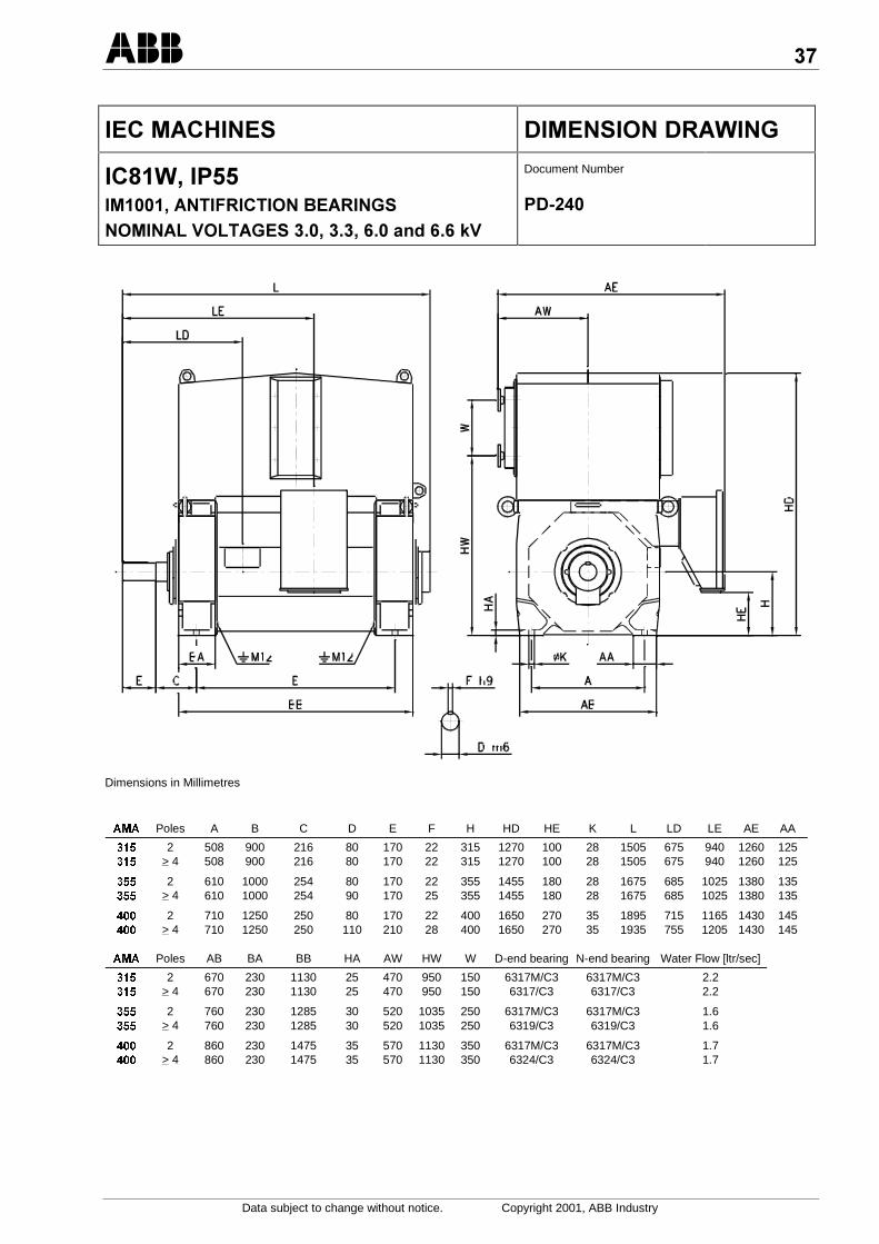
IEC IC81W, IP55 with antifriction bearings, IM 1001 .... 37
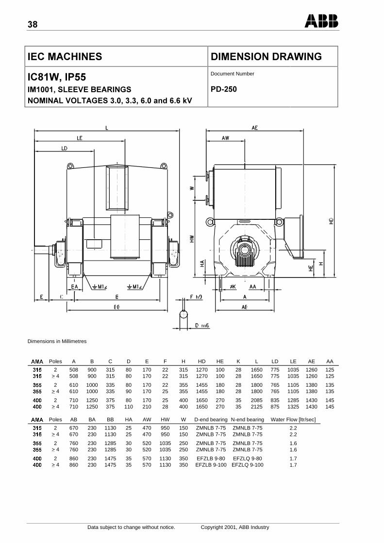
IEC IC81W, IP55 with sleeve bearings, IM 1001 .......... 38
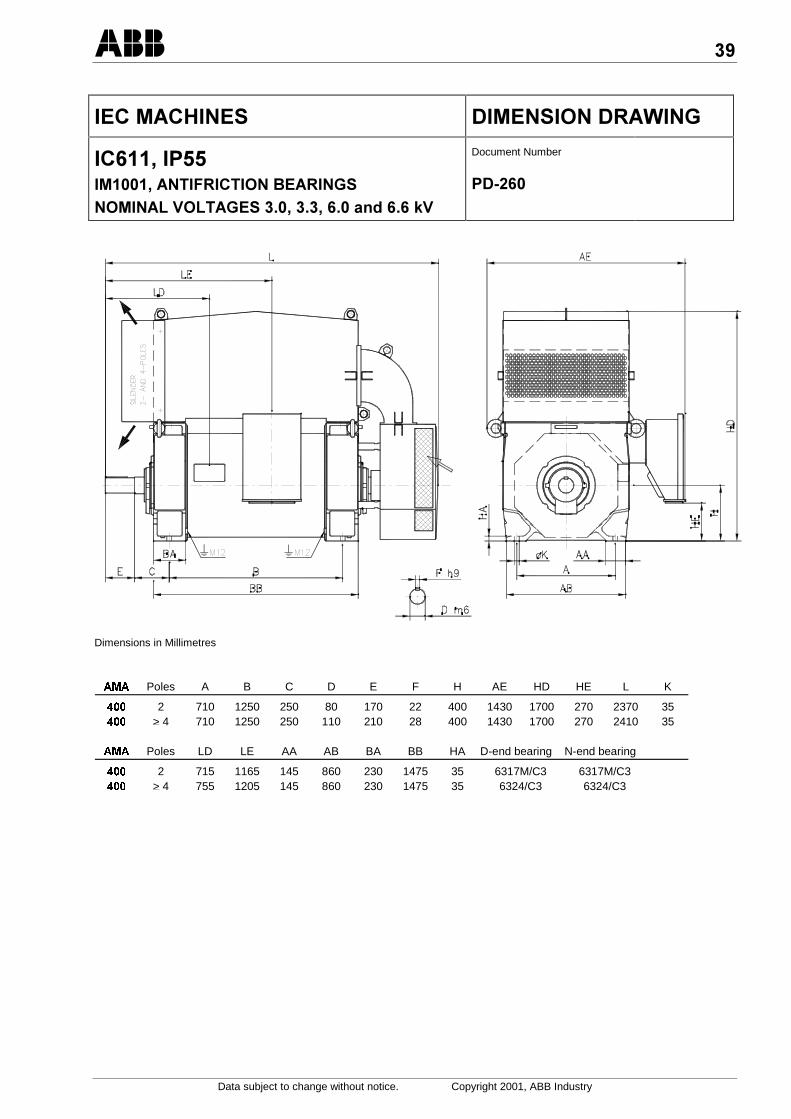
IEC IC611, IP55 with antifriction bearings, IM 1001...... 39
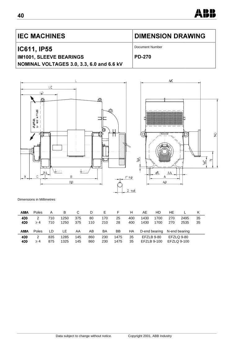
IEC IC611, IP55 with sleeve bearings, IM 1001............ 40
Vertical Machines:
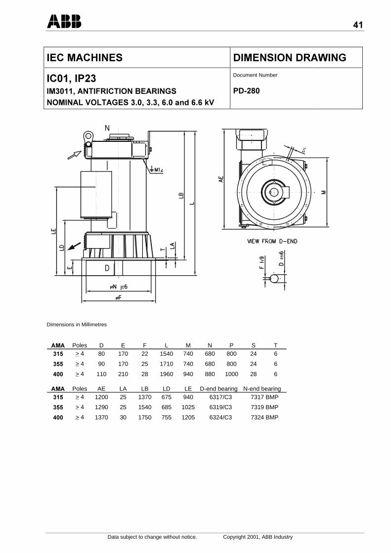
IEC IC01, IP23 with antifriction bearings, IM 3011........ 41
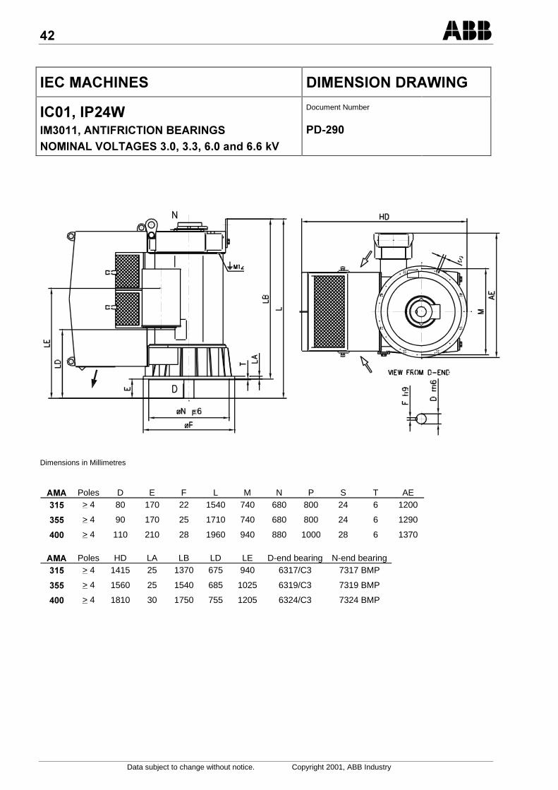
IEC IC01, IP24W with antifriction bearings, IM 3011 .... 42
IEC IC81W, IP55 with antifriction bearings, IM 3011 .... 43
IEC IC611, IP55 with antifriction bearings, IM 3011...... 44
Data subject to change without notice. Copyright 2001, ABB Industry
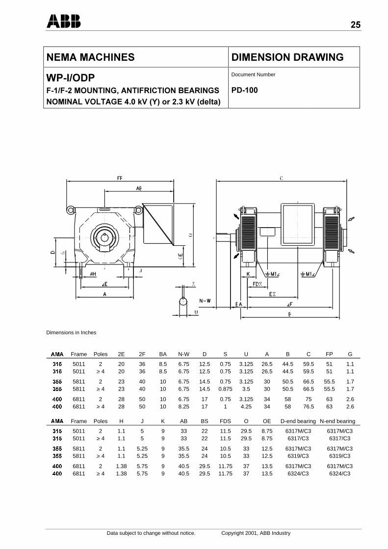
&/.)&/ /& &0+&2
+63636D&&28&30.&!/0&2 &&<=<2/%@=5C7%@=5 *7
Document Number
6
Dimensions in Inches
$0$ Frame Poles 2E 2F BA N-W D S U A B C FP G
5011 2 20 36 8.5 6.75 12.5 0.75 3.125 26.5 44.5 59.5 51 1.1 5011 > 4 20 36 8.5 6.75 12.5 0.75 3.125 26.5 44.5 59.5 51 1.1
5811 2 23 40 10 6.75 14.5 0.75 3.125 30 50.5 66.5 55.5 1.7 5811 > 4 23 40 10 6.75 14.5 0.875 3.5 30 50.5 66.5 55.5 1.7
6811 2 28 50 10 6.75 17 0.75 3.125 34 58 75 63 2.6 6811 > 4 28 50 10 8.25 17 1 4.25 34 58 76.5 63 2.6
$0$ Frame Poles H J K AB BS FDS O OE D-end bearing N-end bearing
5011 2 1.1 5 9 33 22 11.5 29.5 8.75 6317M/C3 6317M/C3 5011 > 4 1.1 5 9 33 22 11.5 29.5 8.75 6317/C3 6317/C3
5811 2 1.1 5.25 9 35.5 24 10.5 33 12.5 6317M/C3 6317M/C3 5811 > 4 1.1 5.25 9 35.5 24 10.5 33 12.5 6319/C3 6319/C3
6811 2 1.38 5.75 9 40.5 29.5 11.75 37 13.5 6317M/C3 6317M/C3 6811 > 4 1.38 5.75 9 40.5 29.5 11.75 37 13.5 6324/C3 6324/C3
,
Data subject to change without notice. Copyright 2001, ABB Industry
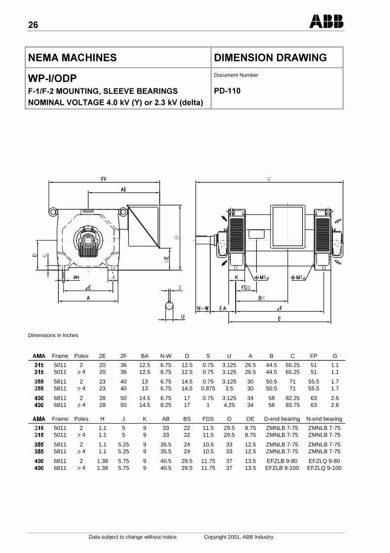
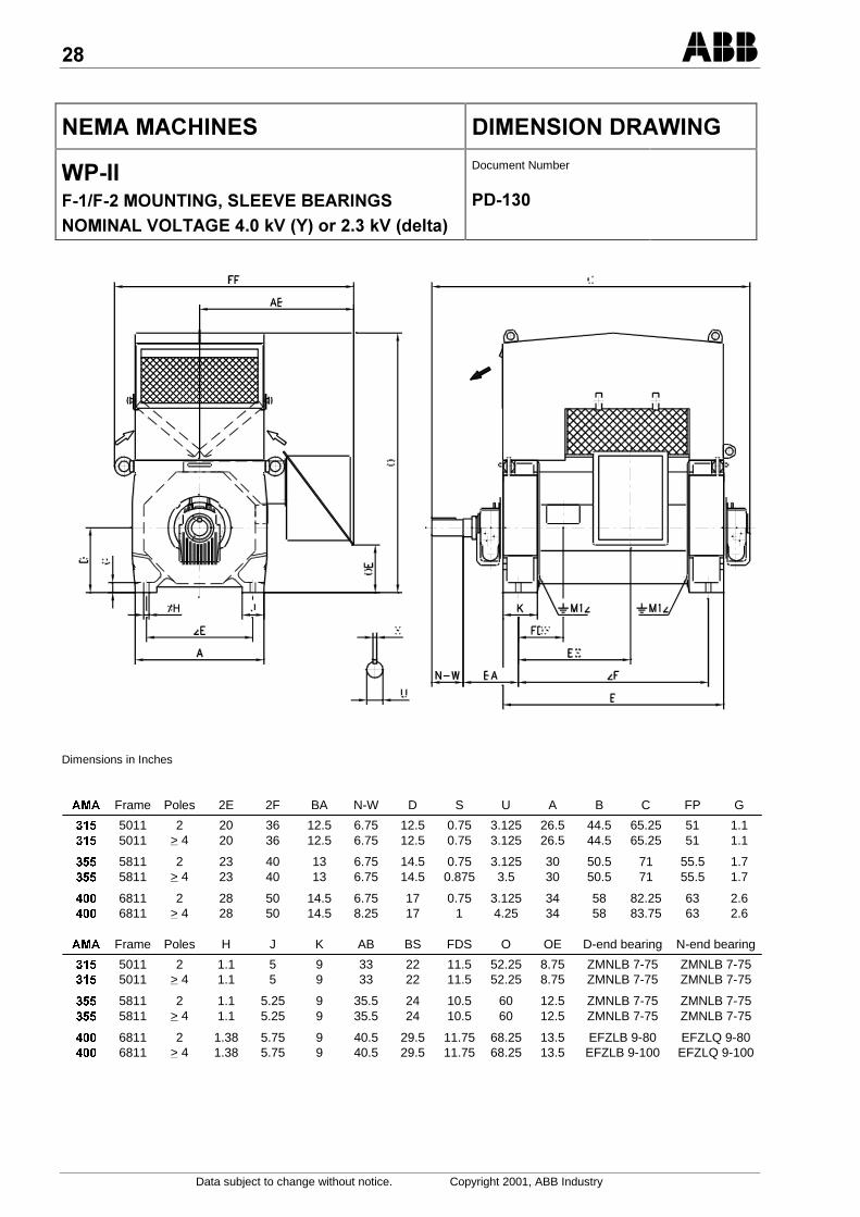
&/.)&/ /& &0+&2
+63636D&&28 <//=/!/0&2 &&<=<2/%@=5C7%@=5 *7
Document Number
6
Dimensions in Inches
$0$ Frame Poles 2E 2F BA N-W D S U A B C FP G
5011 2 20 36 12.5 6.75 12.5 0.75 3.125 26.5 44.5 65.25 51 1.1 5011 > 4 20 36 12.5 6.75 12.5 0.75 3.125 26.5 44.5 65.25 51 1.1
5811 2 23 40 13 6.75 14.5 0.75 3.125 30 50.5 71 55.5 1.7 5811 > 4 23 40 13 6.75 14.5 0.875 3.5 30 50.5 71 55.5 1.7
6811 2 28 50 14.5 6.75 17 0.75 3.125 34 58 82.25 63 2.6 6811 > 4 28 50 14.5 8.25 17 1 4.25 34 58 83.75 63 2.6
$0$ Frame Poles H J K AB BS FDS O OE D-end bearing N-end bearing
5011 2 1.1 5 9 33 22 11.5 29.5 8.75 ZMNLB 7-75 ZMNLB 7-75 5011 > 4 1.1 5 9 33 22 11.5 29.5 8.75 ZMNLB 7-75 ZMNLB 7-75
5811 2 1.1 5.25 9 35.5 24 10.5 33 12.5 ZMNLB 7-75 ZMNLB 7-75 5811 > 4 1.1 5.25 9 35.5 24 10.5 33 12.5 ZMNLB 7-75 ZMNLB 7-75
6811 2 1.38 5.75 9 40.5 29.5 11.75 37 13.5 EFZLB 9-80 EFZLQ 9-80 6811 > 4 1.38 5.75 9 40.5 29.5 11.75 37 13.5 EFZLB 9-100 EFZLQ 9-100
;
Data subject to change without notice. Copyright 2001, ABB Industry
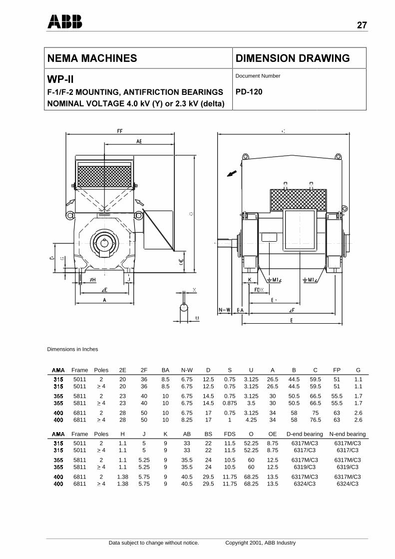
&/.)&/ /& &0+&2
+63636D&&28&30.&!/0&2 &&<=<2/%@=5C7%@=5 *7
Document Number
6
Dimensions in Inches
$0$ Frame Poles 2E 2F BA N-W D S U A B C FP G
5011 2 20 36 8.5 6.75 12.5 0.75 3.125 26.5 44.5 59.5 51 1.1 5011 > 4 20 36 8.5 6.75 12.5 0.75 3.125 26.5 44.5 59.5 51 1.1
5811 2 23 40 10 6.75 14.5 0.75 3.125 30 50.5 66.5 55.5 1.7 5811 > 4 23 40 10 6.75 14.5 0.875 3.5 30 50.5 66.5 55.5 1.7
6811 2 28 50 10 6.75 17 0.75 3.125 34 58 75 63 2.6 6811 > 4 28 50 10 8.25 17 1 4.25 34 58 76.5 63 2.6
$0$ Frame Poles H J K AB BS FDS O OE D-end bearing N-end bearing
5011 2 1.1 5 9 33 22 11.5 52.25 8.75 6317M/C3 6317M/C3 5011 > 4 1.1 5 9 33 22 11.5 52.25 8.75 6317/C3 6317/C3
5811 2 1.1 5.25 9 35.5 24 10.5 60 12.5 6317M/C3 6317M/C3 5811 > 4 1.1 5.25 9 35.5 24 10.5 60 12.5 6319/C3 6319/C3
6811 2 1.38 5.75 9 40.5 29.5 11.75 68.25 13.5 6317M/C3 6317M/C3 6811 > 4 1.38 5.75 9 40.5 29.5 11.75 68.25 13.5 6324/C3 6324/C3
:
Data subject to change without notice. Copyright 2001, ABB Industry
&/.)&/ /& &0+&2
+63636D&&28 <//=/!/0&2 &&<=<2/%@=5C7%@=5 *7
Document Number
6
Dimensions in Inches
$0$ Frame Poles 2E 2F BA N-W D S U A B C FP G
5011 2 20 36 12.5 6.75 12.5 0.75 3.125 26.5 44.5 65.25 51 1.1 5011 > 4 20 36 12.5 6.75 12.5 0.75 3.125 26.5 44.5 65.25 51 1.1
5811 2 23 40 13 6.75 14.5 0.75 3.125 30 50.5 71 55.5 1.7 5811 > 4 23 40 13 6.75 14.5 0.875 3.5 30 50.5 71 55.5 1.7
6811 2 28 50 14.5 6.75 17 0.75 3.125 34 58 82.25 63 2.6 6811 > 4 28 50 14.5 8.25 17 1 4.25 34 58 83.75 63 2.6
$0$ Frame Poles H J K AB BS FDS O OE D-end bearing N-end bearing
5011 2 1.1 5 9 33 22 11.5 52.25 8.75 ZMNLB 7-75 ZMNLB 7-75 5011 > 4 1.1 5 9 33 22 11.5 52.25 8.75 ZMNLB 7-75 ZMNLB 7-75
5811 2 1.1 5.25 9 35.5 24 10.5 60 12.5 ZMNLB 7-75 ZMNLB 7-75 5811 > 4 1.1 5.25 9 35.5 24 10.5 60 12.5 ZMNLB 7-75 ZMNLB 7-75
6811 2 1.38 5.75 9 40.5 29.5 11.75 68.25 13.5 EFZLB 9-80 EFZLQ 9-80 6811 > 4 1.38 5.75 9 40.5 29.5 11.75 68.25 13.5 EFZLB 9-100 EFZLQ 9-100
-
Data subject to change without notice. Copyright 2001, ABB Industry
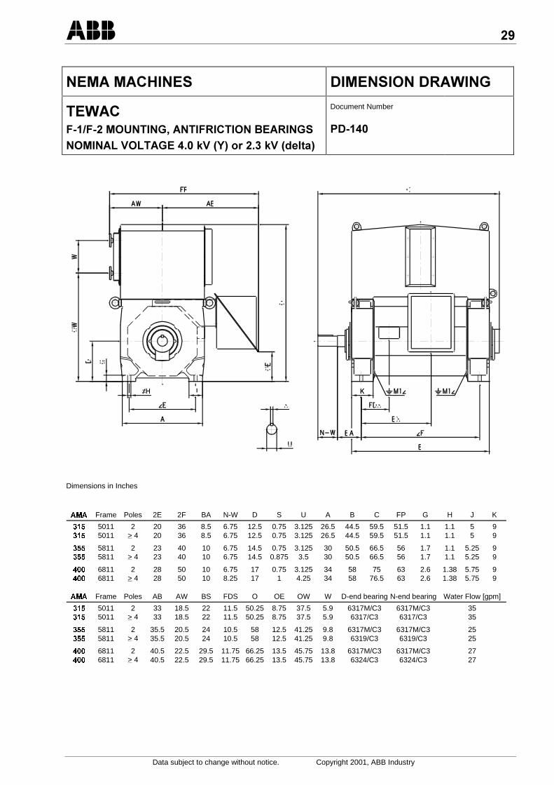
&/.)&/ /& &0+&2
/+.3636D&&28&30.&!/0&2 &&<=<2/%@=5C7%@=5 *7
Document Number
6
Dimensions in Inches
$0$ Frame Poles 2E 2F BA N-W D S U A B C FP G H J K
5011 2 20 36 8.5 6.75 12.5 0.75 3.125 26.5 44.5 59.5 51.5 1.1 1.1 5 9 5011 > 4 20 36 8.5 6.75 12.5 0.75 3.125 26.5 44.5 59.5 51.5 1.1 1.1 5 9
5811 2 23 40 10 6.75 14.5 0.75 3.125 30 50.5 66.5 56 1.7 1.1 5.25 9 5811 > 4 23 40 10 6.75 14.5 0.875 3.5 30 50.5 66.5 56 1.7 1.1 5.25 9
6811 2 28 50 10 6.75 17 0.75 3.125 34 58 75 63 2.6 1.38 5.75 9 6811 > 4 28 50 10 8.25 17 1 4.25 34 58 76.5 63 2.6 1.38 5.75 9
$0$ Frame Poles AB AW BS FDS O OE OW W D-end bearing N-end bearing Water Flow [gpm]
5011 2 33 18.5 22 11.5 50.25 8.75 37.5 5.9 6317M/C3 6317M/C3 35 5011 > 4 33 18.5 22 11.5 50.25 8.75 37.5 5.9 6317/C3 6317/C3 35
5811 2 35.5 20.5 24 10.5 58 12.5 41.25 9.8 6317M/C3 6317M/C3 25 5811 > 4 35.5 20.5 24 10.5 58 12.5 41.25 9.8 6319/C3 6319/C3 25
6811 2 40.5 22.5 29.5 11.75 66.25 13.5 45.75 13.8 6317M/C3 6317M/C3 27 6811 > 4 40.5 22.5 29.5 11.75 66.25 13.5 45.75 13.8 6324/C3 6324/C3 27

Data subject to change without notice. Copyright 2001, ABB Industry
&/.)&/ /& &0+&2
/+.3636D&&28 <//=/!/0&2 &&<=<2/%@=5C7%@=5 *7
Document Number
6
Dimensions in Inches
$0$ Frame Poles 2E 2F BA N-W D S U A B C FP G H J K
5011 2 20 36 12.5 6.75 12.5 0.75 3.125 26.5 44.5 65.25 51.5 1.1 1.1 5 9 5011 > 4 20 36 12.5 6.75 12.5 0.75 3.125 26.5 44.5 65.25 51.5 1.1 1.1 5 9
5811 2 23 40 13 6.75 14.5 0.75 3.125 30 50.5 71 56 1.7 1.1 5.25 9 5811 > 4 23 40 13 6.75 14.5 0.875 3.5 30 50.5 71 56 1.7 1.1 5.25 9
6811 2 28 50 14.5 6.75 17 0.75 3.125 34 58 82.25 63 2.6 1.38 5.75 9 6811 > 4 28 50 14.5 8.25 17 1 4.25 34 58 83.75 63 2.6 1.38 5.75 9
$0$ Frame Poles AB AW BS FDS O OE OW W D-end bearing N-end bearing Water Flow [gpm]
5011 2 33 18.5 22 11.5 50.25 8.75 37.5 5.9 ZMNLB 7-75 ZMNLB 7-75 35 5011 > 4 33 18.5 22 11.5 50.25 8.75 37.5 5.9 ZMNLB 7-75 ZMNLB 7-75 35
5811 2 35.5 20.5 24 10.5 58 12.5 41.25 9.8 ZMNLB 7-75 ZMNLB 7-75 25 5811 > 4 35.5 20.5 24 10.5 58 12.5 41.25 9.8 ZMNLB 7-75 ZMNLB 7-75 25
6811 2 40.5 22.5 29.5 11.75 66.25 13.5 45.75 13.8 EFZLB 9-80 EFZLQ 9-80 27 6811 > 4 40.5 22.5 29.5 11.75 66.25 13.5 45.75 13.8 EFZLB 9-100 EFZLQ 9-100 27

Data subject to change without notice. Copyright 2001, ABB Industry
&/.)&/ /& &0+&2
/.3636D&&28&30.&!/0&2 &&<=<2/%@=5C7%@=5 *7
Document Number
6,
Dimensions in Inches
$0$ Frame Poles 2E 2F BA N-W D S U A B C FP G
6811 2 28 50 10 6.75 17 0.75 3.125 34 58 94 63 2.6 6811 > 4 28 50 10 8.25 17 1 4.25 34 58 95.5 63 2.6
$0$ Frame Poles H J K AB BS FDS O OE D-end bearing N-end bearing
6811 2 1.38 5.75 9 40.5 29.5 11.75 68.25 13.5 6317M/C3 6317M/C3 6811 > 4 1.38 5.75 9 40.5 29.5 11.75 68.25 13.5 6324/C3 6324/C3

Data subject to change without notice. Copyright 2001, ABB Industry
&/.)&/ /& &0+&2
/.3636D&&28 <//=/!/0&2 &&<=<2/%@=5C7%@=5 *7
Document Number
6;
Dimensions in Inches
$0$ Frame Poles 2E 2F BA N-W D S U A B C FP G
6811 2 28 50 14.5 6.75 17 0.75 3.125 34 58 98.5 63 2.6 6811 > 4 28 50 14.5 8.25 17 1 4.25 34 58 100 63 2.6
$0$ Frame Poles H J K AB BS FDS O OE D-end bearing N-end bearing
6811 2 1.38 5.75 9 40.5 29.5 11.75 68.25 13.5 EFZLB 9-80 EFZLQ 9-80 6811 > 4 1.38 5.75 9 40.5 29.5 11.75 68.25 13.5 EFZLB 9-100 EFZLQ 9-100
Data subject to change without notice. Copyright 2001, ABB Industry
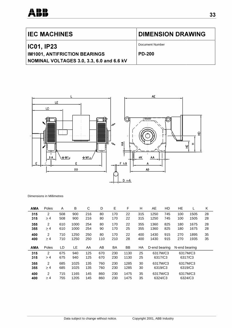
/..)&/ /& &0+&2
.88&30.&!/0&2 &&<=<2/ %8%8,% ,%,@=
Document Number
6
Dimensions in Millimetres
Poles A B C D E F H AE HD HE L K
2 508 900 216 80 170 22 315 1250 745 100 1505 28 > 4 508 900 216 80 170 22 315 1250 745 100 1505 28
2 610 1000 254 80 170 22 355 1360 825 180 1675 28 > 4 610 1000 254 90 170 25 355 1360 825 180 1675 28
2 710 1250 250 80 170 22 400 1430 915 270 1895 35 > 4 710 1250 250 110 210 28 400 1430 915 270 1935 35
Poles LD LE AA AB BA BB HA D-end bearing N-end bearing
2 675 940 125 670 230 1130 25 6317M/C3 6317M/C3 > 4 675 940 125 670 230 1130 25 6317/C3 6317/C3
2 685 1025 135 760 230 1285 30 6317M/C3 6317M/C3 > 4 685 1025 135 760 230 1285 30 6319/C3 6319/C3
2 715 1165 145 860 230 1475 35 6317M/C3 6317M/C3 > 4 755 1205 145 860 230 1475 35 6324/C3 6324/C3
Data subject to change without notice. Copyright 2001, ABB Industry
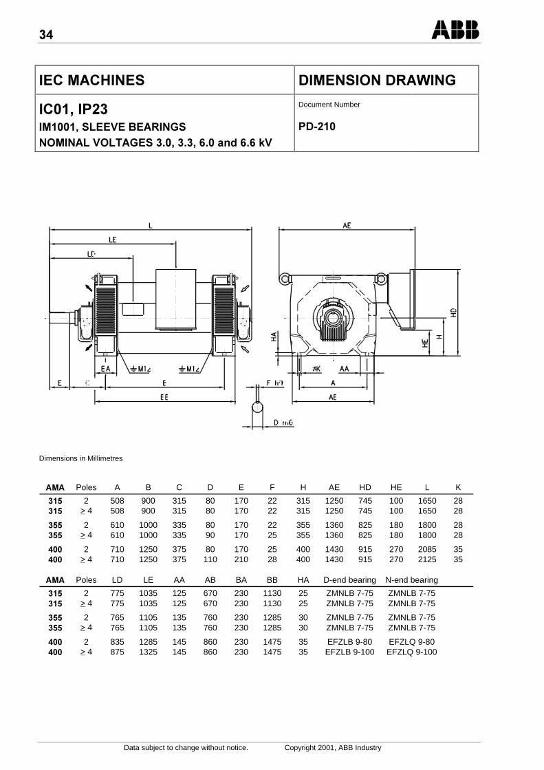
/..)&/ /& &0+&2
.88 <//=/!/0&2 &&<=<2/ %8%8,% ,%,@=
Document Number
6
Dimensions in Millimetres
Poles A B C D E F H AE HD HE L K
2 508 900 315 80 170 22 315 1250 745 100 1650 28 > 4 508 900 315 80 170 22 315 1250 745 100 1650 28
2 610 1000 335 80 170 22 355 1360 825 180 1800 28 > 4 610 1000 335 90 170 25 355 1360 825 180 1800 28
2 710 1250 375 80 170 25 400 1430 915 270 2085 35 > 4 710 1250 375 110 210 28 400 1430 915 270 2125 35
Poles LD LE AA AB BA BB HA D-end bearing N-end bearing
2 775 1035 125 670 230 1130 25 ZMNLB 7-75 ZMNLB 7-75 > 4 775 1035 125 670 230 1130 25 ZMNLB 7-75 ZMNLB 7-75
2 765 1105 135 760 230 1285 30 ZMNLB 7-75 ZMNLB 7-75 > 4 765 1105 135 760 230 1285 30 ZMNLB 7-75 ZMNLB 7-75
2 835 1285 145 860 230 1475 35 EFZLB 9-80 EFZLQ 9-80 > 4 875 1325 145 860 230 1475 35 EFZLB 9-100 EFZLQ 9-100
Data subject to change without notice. Copyright 2001, ABB Industry
/..)&/ /& &0+&2
.8+8&30.&!/0&2 &&<=<2/ %8%8,% ,%,@=
Document Number
6
Dimensions in Millimetres
$0$ Poles A B C D E F H AE HD HE L K
2 508 900 216 80 170 22 315 1250 1320 100 1505 28 > 4 508 900 216 80 170 22 315 1250 1320 100 1505 28
2 610 1000 254 80 170 22 355 1360 1505 180 1675 28 > 4 610 1000 254 90 170 25 355 1360 1505 180 1675 28
2 710 1250 250 80 170 22 400 1430 1700 270 1895 35 > 4 710 1250 250 110 210 28 400 1430 1700 270 1935 35
$0$ Poles LD LE AA AB BA BB HA D-end bearing N-end bearing
2 675 940 125 670 230 1130 25 6317M/C3 6317M/C3 > 4 675 940 125 670 230 1130 25 6317/C3 6317/C3
2 685 1025 135 760 230 1285 30 6317M/C3 6317M/C3 > 4 685 1025 135 760 230 1285 30 6319/C3 6319/C3
2 715 1165 145 860 230 1475 35 6317M/C3 6317M/C3 > 4 755 1205 145 860 230 1475 35 6324/C3 6324/C3
,
Data subject to change without notice. Copyright 2001, ABB Industry
/..)&/ /& &0+&2
.8+8 <//=/!/0&2 &&<=<2/ %8%8,% ,%,@=
Document Number
6
Dimensions in Millimetres
Poles A B C D E F H AE HD HE L K
2 508 900 315 80 170 22 315 1250 1320 100 1650 28 > 4 508 900 315 80 170 22 315 1250 1320 100 1650 28
2 610 1000 335 80 170 22 355 1360 1505 180 1800 28 > 4 610 1000 335 90 170 25 355 1360 1505 180 1800 28
2 710 1250 375 80 170 25 400 1430 1700 270 2085 35 > 4 710 1250 375 110 210 28 400 1430 1700 270 2125 35
Poles LD LE AA AB BA BB HA D-end bearing N-end bearing
2 775 1035 125 670 230 1130 25 ZMNLB 7-75 ZMNLB 7-75 > 4 775 1035 125 670 230 1130 25 ZMNLB 7-75 ZMNLB 7-75
2 765 1105 135 760 230 1285 30 ZMNLB 7-75 ZMNLB 7-75 > 4 765 1105 135 760 230 1285 30 ZMNLB 7-75 ZMNLB 7-75
2 835 1285 145 860 230 1475 35 EFZLB 9-80 EFZLQ 9-80 > 4 875 1325 145 860 230 1475 35 EFZLB 9-100 EFZLQ 9-100
;
Data subject to change without notice. Copyright 2001, ABB Industry
/..)&/ /& &0+&2
.:+88&30.&!/0&2 &&<=<2/ %8%8,% ,%,@=
Document Number
6
Dimensions in Millimetres
$0$ Poles A B C D E F H HD HE K L LD LE AE AA
2 508 900 216 80 170 22 315 1270 100 28 1505 675 940 1260 125 > 4 508 900 216 80 170 22 315 1270 100 28 1505 675 940 1260 125
2 610 1000 254 80 170 22 355 1455 180 28 1675 685 1025 1380 135 > 4 610 1000 254 90 170 25 355 1455 180 28 1675 685 1025 1380 135
2 710 1250 250 80 170 22 400 1650 270 35 1895 715 1165 1430 145 > 4 710 1250 250 110 210 28 400 1650 270 35 1935 755 1205 1430 145
$0$ Poles AB BA BB HA AW HW W D-end bearing N-end bearing Water Flow [ltr/sec]
2 670 230 1130 25 470 950 150 6317M/C3 6317M/C3 2.2 > 4 670 230 1130 25 470 950 150 6317/C3 6317/C3 2.2
2 760 230 1285 30 520 1035 250 6317M/C3 6317M/C3 1.6 > 4 760 230 1285 30 520 1035 250 6319/C3 6319/C3 1.6
2 860 230 1475 35 570 1130 350 6317M/C3 6317M/C3 1.7 > 4 860 230 1475 35 570 1130 350 6324/C3 6324/C3 1.7
:
Data subject to change without notice. Copyright 2001, ABB Industry
/..)&/ /& &0+&2
.:+88 <//=/!/0&2 &&<=<2/ %8%8,% ,%,@=
Document Number
6
Dimensions in Millimetres
$0$ Poles A B C D E F H HD HE K L LD LE AE AA
2 508 900 315 80 170 22 315 1270 100 28 1650 775 1035 1260 125 > 4 508 900 315 80 170 22 315 1270 100 28 1650 775 1035 1260 125
2 610 1000 335 80 170 22 355 1455 180 28 1800 765 1105 1380 135 > 4 610 1000 335 90 170 25 355 1455 180 28 1800 765 1105 1380 135
2 710 1250 375 80 170 25 400 1650 270 35 2085 835 1285 1430 145 > 4 710 1250 375 110 210 28 400 1650 270 35 2125 875 1325 1430 145
$0$ Poles AB BA BB HA AW HW W D-end bearing N-end bearing
2 670 230 1130 25 470 950 150 ZMNLB 7-75 ZMNLB 7-75 > 4 670 230 1130 25 470 950 150 ZMNLB 7-75 ZMNLB 7-75
2 760 230 1285 30 520 1035 250 ZMNLB 7-75 ZMNLB 7-75 > 4 760 230 1285 30 520 1035 250 ZMNLB 7-75 ZMNLB 7-75
2 860 230 1475 35 570 1130 350 EFZLB 9-80 EFZLQ 9-80 > 4 860 230 1475 35 570 1130 350 EFZLB 9-100 EFZLQ 9-100
1.6
1.71.7
Water Flow [ltr/sec]
2.22.2
1.6
-
Data subject to change without notice. Copyright 2001, ABB Industry
/..)&/ /& &0+&2
.,88&30.&!/0&2 &&<=<2/ %8%8,% ,%,@=
Document Number
6,
Dimensions in Millimetres
$0$ Poles A B C D E F H AE HD HE L K
2 710 1250 250 80 170 22 400 1430 1700 270 2370 35 > 4 710 1250 250 110 210 28 400 1430 1700 270 2410 35
$0$ Poles LD LE AA AB BA BB HA D-end bearing N-end bearing
2 715 1165 145 860 230 1475 35 6317M/C3 6317M/C3 > 4 755 1205 145 860 230 1475 35 6324/C3 6324/C3
Data subject to change without notice. Copyright 2001, ABB Industry
/..)&/ /& &0+&2
.,88 <//=/!/0&2 &&<=<2/ %8%8,% ,%,@=
Document Number
6;
Dimensions in Millimetres
$0$ Poles A B C D E F H AE HD HE L K
2 710 1250 375 80 170 25 400 1430 1700 270 2495 35 > 4 710 1250 375 110 210 28 400 1430 1700 270 2535 35
$0$ Poles LD LE AA AB BA BB HA D-end bearing N-end bearing
2 835 1285 145 860 230 1475 35 EFZLB 9-80 EFZLQ 9-80 > 4 875 1325 145 860 230 1475 35 EFZLB 9-100 EFZLQ 9-100
Data subject to change without notice. Copyright 2001, ABB Industry
/..)&/ /& &0+&2
.88&30.&!/0&2 &&<=<2/ %8%8,% ,%,@=
Document Number
6:
Dimensions in Millimetres
Poles D E F L M N P S T > 4 80 170 22 1540 740 680 800 24 6
> 4 90 170 25 1710 740 680 800 24 6
> 4 110 210 28 1960 940 880 1000 28 6
Poles AE LA LB LD LE D-end bearing N-end bearing > 4 1200 25 1370 675 940 6317/C3 7317 BMP
> 4 1290 25 1540 685 1025 6319/C3 7319 BMP
> 4 1370 30 1750 755 1205 6324/C3 7324 BMP
Data subject to change without notice. Copyright 2001, ABB Industry
/..)&/ /& &0+&2
.8+8&30.&!/0&2 &&<=<2/ %8%8,% ,%,@=
Document Number
6-
Dimensions in Millimetres
Poles D E F L M N P S T AE > 4 80 170 22 1540 740 680 800 24 6 1200
> 4 90 170 25 1710 740 680 800 24 6 1290
> 4 110 210 28 1960 940 880 1000 28 6 1370
Poles HD LA LB LD LE D-end bearing N-end bearing > 4 1415 25 1370 675 940 6317/C3 7317 BMP
> 4 1560 25 1540 685 1025 6319/C3 7319 BMP
> 4 1810 30 1750 755 1205 6324/C3 7324 BMP

Data subject to change without notice. Copyright 2001, ABB Industry
/..)&/ /& &0+&2
.:+88&30.&!/0&2 &&<=<2/ %8%8,% ,%,@=
Document Number
6
Dimensions in Millimetres
Poles D E F L M N P S T AE HD LA > 4 80 170 22 1540 740 680 800 24 6 1260 1365 25
> 4 90 170 25 1710 740 680 800 24 6 1380 1510 25
> 4 110 210 28 1960 940 880 1000 28 6 1430 1760 30
Poles LB LD LE AW HW W D-end bearing N-end bearing Water Flow [ltr/sec] > 4 1370 675 940 470 950 150 6317/C3 7317 BMP 2.2
> 4 1540 685 1025 520 1035 250 6319/C3 7319 BMP 1.6
> 4 1750 755 1205 570 1130 350 6324/C3 7324 BMP 1.7

Data subject to change without notice. Copyright 2001, ABB Industry
/..)&/ /& &0+&2
.,88&30.&!/0&2 &&<=<2/ %8%8,% ,%,@=
Document Number
6
Dimensions in Millimetres
Poles D E F L M N P S T AE > 4 110 210 28 2410 940 880 1000 28 6 1370
Poles HD LA LB LD LE D-end bearing N-end bearing > 4 1760 30 2200 755 1205 6324/C3 7324 BMP
Data subject to change without notice. Copyright 2001, ABB Industry
.)/0/% 0<
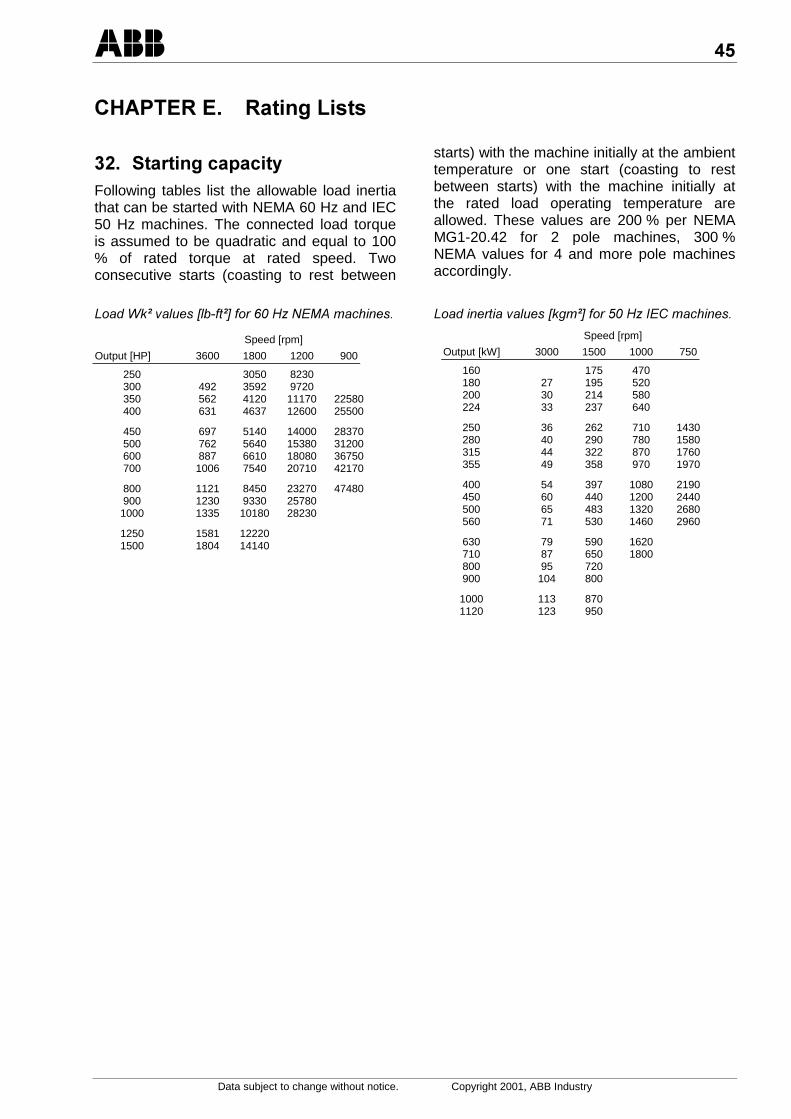
% Following tables list the allowable load inertiathat can be started with NEMA 60 Hz and IEC50 Hz machines. The connected load torqueis assumed to be quadratic and equal to 100% of rated torque at rated speed. Twoconsecutive starts (coasting to rest between
starts) with the machine initially at the ambienttemperature or one start (coasting to restbetween starts) with the machine initially atthe rated load operating temperature areallowed. These values are 200 % per NEMAMG1-20.42 for 2 pole machines, 300 %NEMA values for 4 and more pole machinesaccordingly.
:#,= ")(6".%!=7%>?-0(
Speed [rpm]
Output [HP] 3600 1800 1200 900
250 3050 8230300 492 3592 9720350 562 4120 11170 22580400 631 4637 12600 25500
450 697 5140 14000 28370500 762 5640 15380 31200600 887 6610 18080 36750700 1006 7540 20710 42170
800 1121 8450 23270 47480900 1230 9330 257801000 1335 10180 28230
1250 1581 122201500 1804 14140
:#! ")(6,$=7%>?(
Speed [rpm]
Output [kW] 3000 1500 1000 750
160 175 470180 27 195 520200 30 214 580224 33 237 640
250 36 262 710 1430280 40 290 780 1580315 44 322 870 1760355 49 358 970 1970
400 54 397 1080 2190450 60 440 1200 2440500 65 483 1320 2680560 71 530 1460 2960
630 79 590 1620710 87 650 1800800 95 720900 104 800
1000 113 8701120 123 950
,
Data subject to change without notice. Copyright 2001, ABB Industry
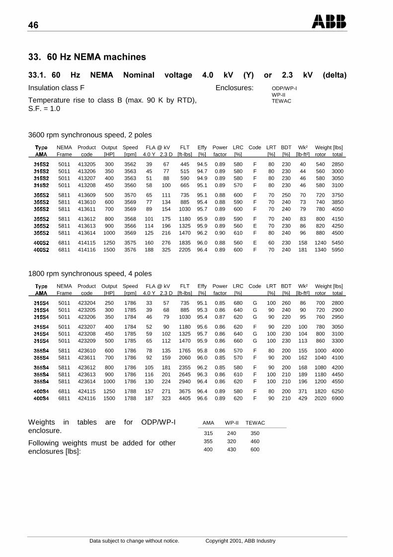
% ,)>&/1
%% , )> &/ &* $* % @= 5C7 % @= 5 *7
Insulation class F
Temperature rise to class B (max. 90 K by RTD),S.F. = 1.0
Enclosures: ODP/WP-IWP-IITEWAC
3600 rpm synchronous speed, 2 poles
7\SH NEMA Product Output Speed FLT Effy Power LRC Code LRT BDT Wk²$0$ Frame code [HP] [rpm] 4.0 Y 2.3 D [ft-lbs] [%] factor [%] [%] [%] [lb-ft²] rotor total
6 5011 413205 300 3562 39 67 445 94.5 0.89 580 F 80 230 40 540 28506 5011 413206 350 3563 45 77 515 94.7 0.89 580 F 80 230 44 560 30006 5011 413207 400 3563 51 88 590 94.9 0.89 580 F 80 230 46 580 30506 5011 413208 450 3560 58 100 665 95.1 0.89 570 F 80 230 46 580 3100
6 5811 413609 500 3570 65 111 735 95.1 0.88 600 F 70 250 70 720 37506 5811 413610 600 3569 77 134 885 95.4 0.88 590 F 70 240 73 740 38506 5811 413611 700 3569 89 154 1030 95.7 0.89 600 F 70 240 79 780 4050
6 5811 413612 800 3568 101 175 1180 95.9 0.89 590 F 70 240 83 800 41506 5811 413613 900 3566 114 196 1325 95.9 0.89 560 E 70 230 86 820 42506 5811 413614 1000 3569 125 216 1470 96.2 0.90 610 F 80 240 96 880 4500
6 6811 414115 1250 3575 160 276 1835 96.0 0.88 560 E 60 230 158 1240 54506 6811 414116 1500 3576 188 325 2205 96.4 0.89 600 F 70 240 181 1340 5950
FLA @ kV Weight [lbs]
1800 rpm synchronous speed, 4 poles
7\SH NEMA Product Output Speed FLT Effy Power LRC Code LRT BDT Wk²$0$ Frame code [HP] [rpm] 4.0 Y 2.3 D [ft-lbs] [%] factor [%] [%] [%] [lb-ft²] rotor total
6 5011 423204 250 1786 33 57 735 95.1 0.85 680 G 100 260 86 700 28006 5011 423205 300 1785 39 68 885 95.3 0.86 640 G 90 240 90 720 29006 5011 423206 350 1784 46 79 1030 95.4 0.87 620 G 90 220 95 760 2950
6 5011 423207 400 1784 52 90 1180 95.6 0.86 620 F 90 220 100 780 30506 5011 423208 450 1785 59 102 1325 95.7 0.86 640 G 100 230 104 800 31006 5011 423209 500 1785 65 112 1470 95.9 0.86 660 G 100 230 113 860 3300
6 5811 423610 600 1786 78 135 1765 95.8 0.86 570 F 80 200 155 1000 40006 5811 423611 700 1786 92 159 2060 96.0 0.85 570 F 90 200 162 1040 4100
6 5811 423612 800 1786 105 181 2355 96.2 0.85 580 F 90 200 168 1080 42006 5811 423613 900 1786 116 201 2645 96.3 0.86 610 F 100 210 189 1180 44506 5811 423614 1000 1786 130 224 2940 96.4 0.86 620 F 100 210 196 1200 4550
6 6811 424115 1250 1788 157 271 3675 96.4 0.89 580 F 80 200 371 1820 62506 6811 424116 1500 1788 187 323 4405 96.6 0.89 620 F 90 210 429 2020 6900
FLA @ kV Weight [lbs]
Weights in tables are for ODP/WP-Ienclosure.
Following weights must be added for otherenclosures [lbs]:
AMA WP-II TEWAC
315 240 350
355 320 460
400 430 600
;
Data subject to change without notice. Copyright 2001, ABB Industry
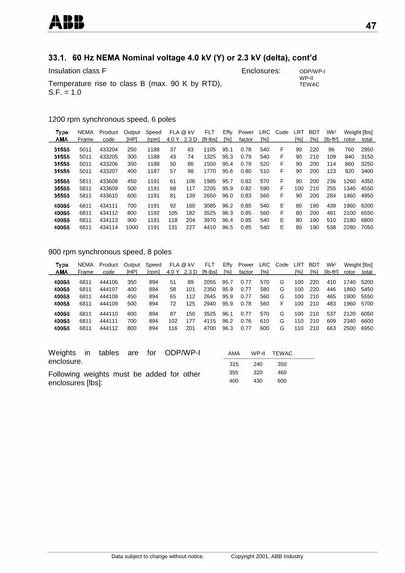
%% ,)>&/&*$*%@=5C7%@=5 *78E
Insulation class F
Temperature rise to class B (max. 90 K by RTD),S.F. = 1.0
Enclosures: ODP/WP-IWP-IITEWAC
1200 rpm synchronous speed, 6 poles
7\SH NEMA Product Output Speed FLT Effy Power LRC Code LRT BDT Wk²$0$ Frame code [HP] [rpm] 4.0 Y 2.3 D [ft-lbs] [%] factor [%] [%] [%] [lb-ft²] rotor total
6 5011 433204 250 1188 37 63 1105 95.1 0.78 540 F 90 220 96 760 29506 5011 433205 300 1188 43 74 1325 95.3 0.79 540 F 90 210 109 840 31506 5011 433206 350 1188 50 86 1550 95.4 0.79 520 F 90 200 114 860 32506 5011 433207 400 1187 57 98 1770 95.6 0.80 510 F 90 200 123 920 3400
6 5811 433608 450 1191 61 106 1985 95.7 0.82 570 F 90 200 236 1260 43506 5811 433609 500 1191 68 117 2205 95.9 0.82 590 F 100 210 255 1340 45506 5811 433610 600 1191 81 139 2650 96.0 0.83 560 F 90 200 284 1460 4850
6 6811 434111 700 1191 92 160 3085 96.2 0.85 540 E 80 190 439 1960 62006 6811 434112 800 1192 105 182 3525 96.3 0.85 560 F 80 200 481 2100 65506 6811 434113 900 1191 118 204 3970 96.4 0.85 540 E 80 190 510 2180 68006 6811 434114 1000 1191 131 227 4410 96.5 0.85 540 E 80 190 538 2280 7050
FLA @ kV Weight [lbs]
900 rpm synchronous speed, 8 poles
7\SH NEMA Product Output Speed FLT Effy Power LRC Code LRT BDT Wk²$0$ Frame code [HP] [rpm] 4.0 Y 2.3 D [ft-lbs] [%] factor [%] [%] [%] [lb-ft²] rotor total
6 6811 444106 350 894 51 89 2055 95.7 0.77 570 G 100 220 410 1740 52006 6811 444107 400 894 58 101 2350 95.9 0.77 580 G 100 220 446 1860 54506 6811 444108 450 894 65 112 2645 95.9 0.77 560 G 100 210 465 1900 55506 6811 444109 500 894 72 125 2940 95.9 0.78 560 F 100 210 483 1960 5700
6 6811 444110 600 894 87 150 3525 96.1 0.77 570 G 100 210 537 2120 60506 6811 444111 700 894 102 177 4115 96.2 0.76 610 G 110 210 609 2340 66006 6811 444112 800 894 116 201 4700 96.3 0.77 600 G 110 210 663 2500 6950
FLA @ kV Weight [lbs]
Weights in tables are for ODP/WP-Ienclosure.
Following weights must be added for otherenclosures [lbs]:
AMA WP-II TEWAC
315 240 350
355 320 460
400 430 600

:
Data subject to change without notice. Copyright 2001, ABB Industry
%% ,)>&/&*$*%@=5C7%@=5 *78/.
Insulation class F
Temperature rise to class B (max. 90 K by RTD), S.F. = 1.0
3600 rpm synchronous speed, 2 poles
7\SH NEMA Product Output Speed FLT Effy Power LRC Code LRT BDT Wk²$0$ Frame code [HP] [rpm] 4.0 Y 2.3 D [ft-lbs] [%] factor [%] [%] [%] [lb-ft²] rotor total
6$ 6811 414312 800 3578 104 180 1175 95.0 0.87 620 F 70 260 156 1200 61006$ 6811 414313 900 3577 116 201 1320 95.1 0.88 570 F 60 240 162 1240 62006$ 6811 414314 1000 3579 129 223 1470 95.4 0.87 640 G 70 260 173 1300 64506$ 6811 414315 1250 3579 157 272 1835 95.8 0.89 640 F 70 260 196 1400 6900
FLA @ kV Weight [lbs]
1800 rpm synchronous speed, 4 poles
7\SH NEMA Product Output Speed FLT Effy Power LRC Code LRT BDT Wk²$0$ Frame code [HP] [rpm] 4.0 Y 2.3 D [ft-lbs] [%] factor [%] [%] [%] [lb-ft²] rotor total
6$ 6811 424312 800 1788 102 177 2350 95.2 0.88 570 F 70 210 351 1720 66506$ 6811 424313 900 1789 114 197 2645 95.5 0.89 600 F 80 210 386 1840 70506$ 6811 424314 1000 1788 126 218 2940 95.6 0.89 590 F 80 210 409 1920 72506$ 6811 424315 1250 1788 156 270 3675 96.1 0.90 600 F 80 200 467 2120 7900
FLA @ kV Weight [lbs]
1200 rpm synchronous speed, 6 poles
7\SH NEMA Product Output Speed FLT Effy Power LRC Code LRT BDT Wk²$0$ Frame code [HP] [rpm] 4.0 Y 2.3 D [ft-lbs] [%] factor [%] [%] [%] [lb-ft²] rotor total
6$ 6811 434309 500 1193 68 118 2200 95.5 0.83 640 G 100 240 434 1900 68006$ 6811 434310 600 1193 80 139 2645 95.8 0.84 620 G 90 220 477 2040 72006$ 6811 434311 700 1193 93 161 3085 95.9 0.84 630 G 100 230 519 2180 7550
6$ 6811 434312 800 1192 106 183 3525 96.1 0.84 600 F 90 220 548 2280 78006$ 6811 434313 900 1192 119 206 3965 96.2 0.84 600 F 90 210 576 2380 8050
FLA @ kV Weight [lbs]
900 rpm synchronous speed, 8 poles
7\SH NEMA Product Output Speed FLT Effy Power LRC Code LRT BDT Wk²$0$ Frame code [HP] [rpm] 4.0 Y 2.3 D [ft-lbs] [%] factor [%] [%] [%] [lb-ft²] rotor total
6$ 6811 444305 300 895 46 79 1760 95.2 0.74 640 H 110 250 448 1840 62506$ 6811 444306 350 895 53 91 2055 95.4 0.75 640 H 110 250 484 1960 65006$ 6811 444307 400 895 59 103 2350 95.5 0.76 620 H 110 240 503 2000 66006$ 6811 444308 450 894 67 115 2645 95.6 0.76 610 G 110 230 521 2060 6700
6$ 6811 444309 500 895 75 130 2935 95.8 0.75 650 H 120 250 575 2220 71006$ 6811 444310 600 895 91 158 3520 95.9 0.74 680 J 130 250 647 2440 76006$ 6811 444311 700 895 105 182 4110 96.1 0.74 660 H 130 240 701 2600 8000
FLA @ kV Weight [lbs]

-
Data subject to change without notice. Copyright 2001, ABB Industry
% )>/.1
%% )>/.&*$*%@=
Insulation class F
Temperature rise to class B (max. 80 K by res.)
Enclosures: IC01, IP23IC01, IP24WIC81W, IP55
3000 rpm synchronous speed, 2 poles
7\SH Product Output Speed In Tn Eff Power Is Ts Tmax Inertia$0$ code [kW] [rpm] [A] [Nm] [%] factor In Tn Tn [kgm²] rotor total
6 313106 180 2957 43 581 94.3 0.87 5.0 0.75 2.10 1.6 230 12406 313107 200 2956 48 646 94.1 0.85 4.8 0.70 2.00 1.6 230 12406 313108 224 2956 48 724 94.1 0.85 4.8 0.70 2.00 1.6 230 12406 313109 250 2957 59 807 94.6 0.86 4.9 0.75 2.05 1.7 240 1300
6 313110 280 2957 59 904 94.6 0.86 4.9 0.75 2.05 1.7 240 13006 313111 315 2958 73 1017 95.0 0.87 5.2 0.80 2.10 2.0 260 14006 313112 355 2960 81 1145 95.2 0.88 5.4 0.85 2.20 2.1 280 1480
6 313513 400 2964 92 1289 95.4 0.88 5.2 0.70 2.15 3.0 330 17206 313514 450 2966 102 1449 95.7 0.88 5.6 0.75 2.30 3.2 340 18006 313515 500 2965 114 1611 95.7 0.89 5.2 0.70 2.15 3.4 350 1840
6 313516 560 2965 127 1804 95.9 0.89 5.6 0.75 2.25 3.5 360 19006 313517 630 2968 143 2027 95.9 0.88 5.8 0.80 2.35 3.8 380 19606 313518 710 2967 160 2285 96.0 0.89 5.8 0.80 2.35 4.1 400 2060
6 314019 800 2976 183 2567 96.2 0.87 5.7 0.70 2.25 6.9 570 25406 314020 900 2976 201 2888 96.4 0.89 5.9 0.75 2.25 7.6 610 27206 314021 1000 2975 224 3210 96.4 0.89 5.5 0.70 2.15 7.9 620 27806 314022 1120 2974 248 3597 96.5 0.90 5.5 0.70 2.15 8.3 650 2900
Weight [kg]
1500 rpm synchronous speed, 4 poles
7\SH Product Output Speed In Tn Eff Power Is Ts Tmax Inertia$0$ code [kW] [rpm] [A] [Nm] [%] factor In Tn Tn [kgm²] rotor total
6 323105 160 1483 38 1030 94.9 0.87 5.6 0.85 2.15 3.5 300 12406 323106 180 1482 43 1160 94.7 0.86 5.3 0.80 2.05 3.5 300 12406 323107 200 1481 48 1290 94.9 0.86 5.2 0.80 2.00 3.5 300 1240
6 323108 224 1481 53 1444 95.0 0.86 5.2 0.80 2.00 3.6 320 12806 323109 250 1481 59 1612 95.2 0.86 5.3 0.85 1.95 3.8 330 13206 323110 280 1482 66 1804 95.4 0.86 5.5 0.90 2.00 4.0 340 1360
6 323111 315 1482 73 2029 95.8 0.86 5.6 0.95 2.00 4.4 370 14406 323112 355 1481 84 2289 95.4 0.85 5.3 0.90 2.00 4.4 370 14206 323113 400 1482 94 2577 95.6 0.85 5.6 0.95 2.00 4.8 390 1500
6 323514 450 1485 104 2895 96.0 0.86 5.3 0.90 1.85 6.8 470 18806 323515 500 1486 116 3213 96.2 0.86 5.8 1.00 2.05 7.4 500 19606 323516 560 1486 128 3600 96.3 0.87 5.7 1.00 1.95 8.0 530 2040
6 323517 630 1485 143 4051 96.3 0.87 5.6 1.00 1.90 8.6 560 21406 323518 710 1485 163 4565 96.4 0.87 5.7 1.05 1.95 8.8 580 2180
6 324019 800 1487 182 5136 96.4 0.88 5.7 0.80 2.00 14.7 790 27406 324020 900 1488 204 5778 96.5 0.88 5.8 0.85 2.05 15.7 820 28606 324021 1000 1488 225 6418 96.7 0.88 5.9 0.90 2.10 17.1 880 30406 324022 1120 1489 255 7184 96.8 0.87 6.4 1.00 2.30 18.1 920 3160
Weight [kg]
Weights in tables are for IC01, IP23enclosure
Following weights must be added for otherenclosures [kg]:
AMA IC01, IP24W IC81W, IP55
315 110 160355 150 210400 200 270
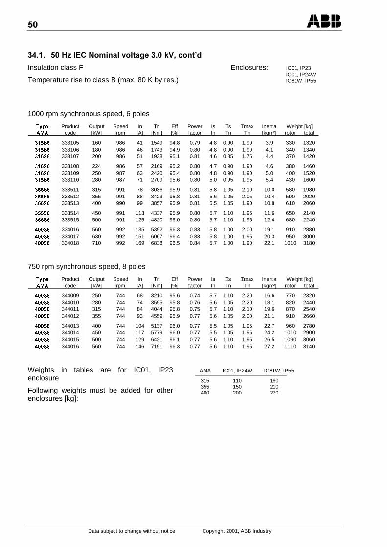
Data subject to change without notice. Copyright 2001, ABB Industry
%% )>/.&*$*%@=8E
Insulation class F
Temperature rise to class B (max. 80 K by res.)
Enclosures: IC01, IP23IC01, IP24WIC81W, IP55
1000 rpm synchronous speed, 6 poles
7\SH Product Output Speed In Tn Eff Power Is Ts Tmax Inertia$0$ code [kW] [rpm] [A] [Nm] [%] factor In Tn Tn [kgm²] rotor total
6 333105 160 986 41 1549 94.8 0.79 4.8 0.90 1.90 3.9 330 13206 333106 180 986 46 1743 94.9 0.80 4.8 0.90 1.90 4.1 340 13406 333107 200 986 51 1938 95.1 0.81 4.6 0.85 1.75 4.4 370 1420
6 333108 224 986 57 2169 95.2 0.80 4.7 0.90 1.90 4.6 380 14606 333109 250 987 63 2420 95.4 0.80 4.8 0.90 1.90 5.0 400 15206 333110 280 987 71 2709 95.6 0.80 5.0 0.95 1.95 5.4 430 1600
6 333511 315 991 78 3036 95.9 0.81 5.8 1.05 2.10 10.0 580 19806 333512 355 991 88 3423 95.8 0.81 5.6 1.05 2.05 10.4 590 20206 333513 400 990 99 3857 95.9 0.81 5.5 1.05 1.90 10.8 610 2060
6 333514 450 991 113 4337 95.9 0.80 5.7 1.10 1.95 11.6 650 21406 333515 500 991 125 4820 96.0 0.80 5.7 1.10 1.95 12.4 680 2240
6 334016 560 992 135 5392 96.3 0.83 5.8 1.00 2.00 19.1 910 28806 334017 630 992 151 6067 96.4 0.83 5.8 1.00 1.95 20.3 950 30006 334018 710 992 169 6838 96.5 0.84 5.7 1.00 1.90 22.1 1010 3180
Weight [kg]
750 rpm synchronous speed, 8 poles
7\SH Product Output Speed In Tn Eff Power Is Ts Tmax Inertia$0$ code [kW] [rpm] [A] [Nm] [%] factor In Tn Tn [kgm²] rotor total
6 344009 250 744 68 3210 95.6 0.74 5.7 1.10 2.20 16.6 770 23206 344010 280 744 74 3595 95.8 0.76 5.6 1.05 2.20 18.1 820 24406 344011 315 744 84 4044 95.8 0.75 5.7 1.10 2.10 19.6 870 25406 344012 355 744 93 4559 95.9 0.77 5.6 1.05 2.00 21.1 910 2660
6 344013 400 744 104 5137 96.0 0.77 5.5 1.05 1.95 22.7 960 27806 344014 450 744 117 5779 96.0 0.77 5.5 1.05 1.95 24.2 1010 29006 344015 500 744 129 6421 96.1 0.77 5.6 1.10 1.95 26.5 1090 30606 344016 560 744 146 7191 96.3 0.77 5.6 1.10 1.95 27.2 1110 3140
Weight [kg]
Weights in tables are for IC01, IP23enclosure
Following weights must be added for otherenclosures [kg]:
AMA IC01, IP24W IC81W, IP55
315 110 160355 150 210400 200 270
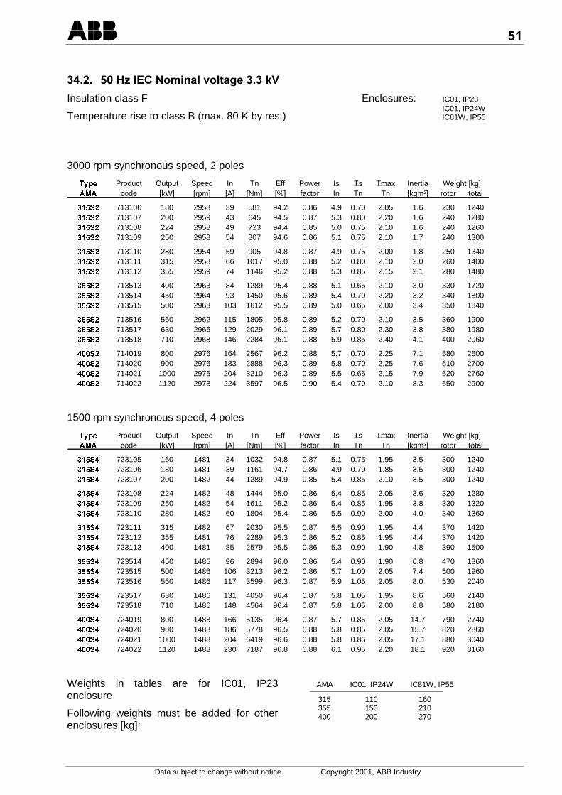
Data subject to change without notice. Copyright 2001, ABB Industry
%% )>/.&*$*%@=
Insulation class F
Temperature rise to class B (max. 80 K by res.)
Enclosures: IC01, IP23IC01, IP24WIC81W, IP55
3000 rpm synchronous speed, 2 poles
7\SH Product Output Speed In Tn Eff Power Is Ts Tmax Inertia$0$ code [kW] [rpm] [A] [Nm] [%] factor In Tn Tn [kgm²] rotor total
6 713106 180 2958 39 581 94.2 0.86 4.9 0.70 2.05 1.6 230 12406 713107 200 2959 43 645 94.5 0.87 5.3 0.80 2.20 1.6 240 12806 713108 224 2958 49 723 94.4 0.85 5.0 0.75 2.10 1.6 240 12606 713109 250 2958 54 807 94.6 0.86 5.1 0.75 2.10 1.7 240 1300
6 713110 280 2954 59 905 94.8 0.87 4.9 0.75 2.00 1.8 250 13406 713111 315 2958 66 1017 95.0 0.88 5.2 0.80 2.10 2.0 260 14006 713112 355 2959 74 1146 95.2 0.88 5.3 0.85 2.15 2.1 280 1480
6 713513 400 2963 84 1289 95.4 0.88 5.1 0.65 2.10 3.0 330 17206 713514 450 2964 93 1450 95.6 0.89 5.4 0.70 2.20 3.2 340 18006 713515 500 2963 103 1612 95.5 0.89 5.0 0.65 2.00 3.4 350 1840
6 713516 560 2962 115 1805 95.8 0.89 5.2 0.70 2.10 3.5 360 19006 713517 630 2966 129 2029 96.1 0.89 5.7 0.80 2.30 3.8 380 19806 713518 710 2968 146 2284 96.1 0.88 5.9 0.85 2.40 4.1 400 2060
6 714019 800 2976 164 2567 96.2 0.88 5.7 0.70 2.25 7.1 580 26006 714020 900 2976 183 2888 96.3 0.89 5.8 0.70 2.25 7.6 610 27006 714021 1000 2975 204 3210 96.3 0.89 5.5 0.65 2.15 7.9 620 27606 714022 1120 2973 224 3597 96.5 0.90 5.4 0.70 2.10 8.3 650 2900
Weight [kg]
1500 rpm synchronous speed, 4 poles
7\SH Product Output Speed In Tn Eff Power Is Ts Tmax Inertia$0$ code [kW] [rpm] [A] [Nm] [%] factor In Tn Tn [kgm²] rotor total
6 723105 160 1481 34 1032 94.8 0.87 5.1 0.75 1.95 3.5 300 12406 723106 180 1481 39 1161 94.7 0.86 4.9 0.70 1.85 3.5 300 12406 723107 200 1482 44 1289 94.9 0.85 5.4 0.85 2.10 3.5 300 1240
6 723108 224 1482 48 1444 95.0 0.86 5.4 0.85 2.05 3.6 320 12806 723109 250 1482 54 1611 95.2 0.86 5.4 0.85 1.95 3.8 330 13206 723110 280 1482 60 1804 95.4 0.86 5.5 0.90 2.00 4.0 340 1360
6 723111 315 1482 67 2030 95.5 0.87 5.5 0.90 1.95 4.4 370 14206 723112 355 1481 76 2289 95.3 0.86 5.2 0.85 1.95 4.4 370 14206 723113 400 1481 85 2579 95.5 0.86 5.3 0.90 1.90 4.8 390 1500
6 723514 450 1485 96 2894 96.0 0.86 5.4 0.90 1.90 6.8 470 18606 723515 500 1486 106 3213 96.2 0.86 5.7 1.00 2.05 7.4 500 19606 723516 560 1486 117 3599 96.3 0.87 5.9 1.05 2.05 8.0 530 2040
6 723517 630 1486 131 4050 96.4 0.87 5.8 1.05 1.95 8.6 560 21406 723518 710 1486 148 4564 96.4 0.87 5.8 1.05 2.00 8.8 580 2180
6 724019 800 1488 166 5135 96.4 0.87 5.7 0.85 2.05 14.7 790 27406 724020 900 1488 186 5778 96.5 0.88 5.8 0.85 2.05 15.7 820 28606 724021 1000 1488 204 6419 96.6 0.88 5.8 0.85 2.05 17.1 880 30406 724022 1120 1488 230 7187 96.8 0.88 6.1 0.95 2.20 18.1 920 3160
Weight [kg]
Weights in tables are for IC01, IP23enclosure
Following weights must be added for otherenclosures [kg]:
AMA IC01, IP24W IC81W, IP55
315 110 160355 150 210400 200 270

Data subject to change without notice. Copyright 2001, ABB Industry
%% )>/.&*$*%@=8E
Insulation class F
Temperature rise to class B (max. 80 K by res.)
Enclosures: IC01, IP23IC01, IP24WIC81W, IP55
1000 rpm synchronous speed, 6 poles
7\SH Product Output Speed In Tn Eff Power Is Ts Tmax Inertia$0$ code [kW] [rpm] [A] [Nm] [%] factor In Tn Tn [kgm²] rotor total
6 733105 160 987 38 1548 94.9 0.79 5.0 0.95 2.00 3.9 330 13206 733106 180 987 42 1742 95.0 0.79 4.9 0.90 1.95 4.1 340 13406 733107 200 986 46 1937 95.1 0.80 4.7 0.85 1.85 4.4 370 1420
6 733108 224 986 52 2169 95.2 0.80 4.7 0.90 1.90 4.6 380 14606 733109 250 986 57 2421 95.3 0.80 4.7 0.90 1.85 5.0 400 15206 733110 280 986 64 2711 95.5 0.80 4.8 0.90 1.90 5.4 430 1600
6 733511 315 990 70 3037 95.8 0.82 5.6 1.00 2.00 10.0 580 19806 733512 355 991 81 3420 96.0 0.80 5.9 1.15 2.10 10.4 590 20406 733513 400 991 91 3855 95.9 0.80 5.8 1.10 2.00 10.8 610 2060
6 733514 450 991 104 4336 95.9 0.79 5.9 1.20 2.05 11.6 650 21406 733515 500 991 115 4818 96.0 0.79 5.8 1.15 2.00 12.4 680 2240
6 734016 560 992 123 5391 96.3 0.83 5.8 1.00 2.00 19.1 910 28606 734017 630 992 138 6066 96.4 0.83 5.9 1.00 2.00 20.3 950 30006 734018 710 992 154 6838 96.5 0.84 5.7 1.00 1.90 22.1 1010 3160
Weight [kg]
750 rpm synchronous speed, 8 poles
7\SH Product Output Speed In Tn Eff Power Is Ts Tmax Inertia$0$ code [kW] [rpm] [A] [Nm] [%] factor In Tn Tn [kgm²] rotor total
6 744009 250 744 61 3211 95.6 0.75 5.5 1.05 2.15 16.6 770 23206 744010 280 744 68 3595 95.7 0.75 5.6 1.10 2.15 18.1 820 24406 744011 315 744 75 4045 95.9 0.77 5.6 1.05 2.15 19.6 870 25606 744012 355 744 85 4557 95.9 0.76 5.7 1.10 2.05 21.1 910 2660
6 744013 400 744 95 5136 96.0 0.77 5.6 1.05 2.00 22.7 960 27806 744014 450 744 106 5779 96.0 0.77 5.5 1.05 1.95 24.2 1010 28806 744015 500 744 117 6422 96.1 0.78 5.5 1.05 1.90 26.5 1090 30606 744016 560 744 133 7190 96.2 0.77 5.7 1.15 2.00 28.0 1130 3180
Weight [kg]
Weights in tables are for IC01, IP23enclosure
Following weights must be added for otherenclosures [kg]:
AMA IC01, IP24W IC81W, IP55
315 110 160355 150 210400 200 270

Data subject to change without notice. Copyright 2001, ABB Industry
%% )>/.&*$*,%@=
Insulation class F
Temperature rise to class B (max. 80 K by res.)
Enclosures: IC01, IP23IC01, IP24WIC81W, IP55
3000 rpm synchronous speed, 2 poles
7\SH Product Output Speed In Tn Eff Power Is Ts Tmax Inertia$0$ code [kW] [rpm] [A] [Nm] [%] factor In Tn Tn [kgm²] rotor total
6 613509 250 2967 29 805 94.6 0.88 5.3 0.65 2.20 2.7 310 16006 613510 280 2968 32 901 94.9 0.88 5.5 0.65 2.25 2.8 320 16406 613511 315 2969 36 1013 95.1 0.88 5.7 0.70 2.30 3.0 330 17006 613512 355 2967 41 1143 95.4 0.89 5.6 0.70 2.25 3.1 330 1740
6 613513 400 2970 46 1286 95.6 0.88 6.1 0.80 2.50 3.2 340 17806 613514 450 2969 51 1448 95.6 0.88 5.8 0.75 2.35 3.4 350 18206 613515 500 2969 57 1608 95.8 0.88 6.1 0.85 2.45 3.5 360 1860
6 613516 560 2969 64 1801 95.9 0.88 6.1 0.85 2.50 3.6 370 19206 613517 630 2969 71 2027 96.0 0.89 6.1 0.85 2.45 3.9 390 20006 613518 710 2969 80 2284 96.1 0.89 6.2 0.90 2.45 4.2 410 2080
6 614019 800 2976 90 2567 96.2 0.89 5.7 0.70 2.25 7.1 580 25806 614020 900 2976 100 2888 96.4 0.90 5.8 0.75 2.30 7.9 620 27606 614021 1000 2975 112 3210 96.2 0.90 5.4 0.65 2.15 8.1 630 28206 614022 1120 2973 123 3597 96.4 0.90 5.4 0.70 2.10 8.6 660 2920
Weight [kg]
1500 rpm synchronous speed, 4 poles
7\SH Product Output Speed In Tn Eff Power Is Ts Tmax Inertia$0$ code [kW] [rpm] [A] [Nm] [%] factor In Tn Tn [kgm²] rotor total
6 623507 200 1487 24 1284 95.2 0.86 6.0 0.90 2.25 5.7 410 16606 623508 224 1488 27 1437 95.4 0.85 6.3 1.00 2.40 5.7 410 16606 623509 250 1487 30 1606 95.4 0.85 5.7 0.90 2.15 5.7 410 16606 623510 280 1487 33 1798 95.6 0.85 5.9 0.95 2.15 6.0 430 1720
6 623511 315 1488 37 2021 95.8 0.85 6.4 1.00 2.25 6.6 460 18006 623512 355 1488 42 2278 96.0 0.85 6.5 1.10 2.30 6.8 470 18606 623513 400 1487 47 2569 96.0 0.86 6.0 1.00 2.10 7.1 490 19006 623514 450 1486 52 2893 96.0 0.87 5.6 0.95 1.90 7.4 500 1940
6 623515 500 1485 57 3214 96.1 0.87 5.6 0.95 1.90 7.7 520 19806 623516 560 1485 64 3602 96.1 0.88 5.4 0.95 1.80 8.3 550 20806 623517 630 1486 72 4049 96.2 0.87 5.8 1.00 1.95 8.8 580 21606 623518 710 1485 81 4566 96.3 0.87 5.5 1.00 1.85 9.1 590 2220
6 624019 800 1488 91 5136 96.4 0.88 5.7 0.85 2.05 14.7 790 27206 624020 900 1488 102 5777 96.5 0.88 5.8 0.85 2.05 15.7 820 28406 624021 1000 1488 113 6418 96.6 0.88 6.0 0.90 2.15 17.1 880 30206 624022 1120 1489 128 7184 96.7 0.87 6.3 1.00 2.30 18.1 920 3140
Weight [kg]
Weights in tables are for IC01, IP23enclosure
Following weights must be added for otherenclosures [kg]:
AMA IC01, IP24W IC81W, IP55
315 110 160355 150 210400 200 270
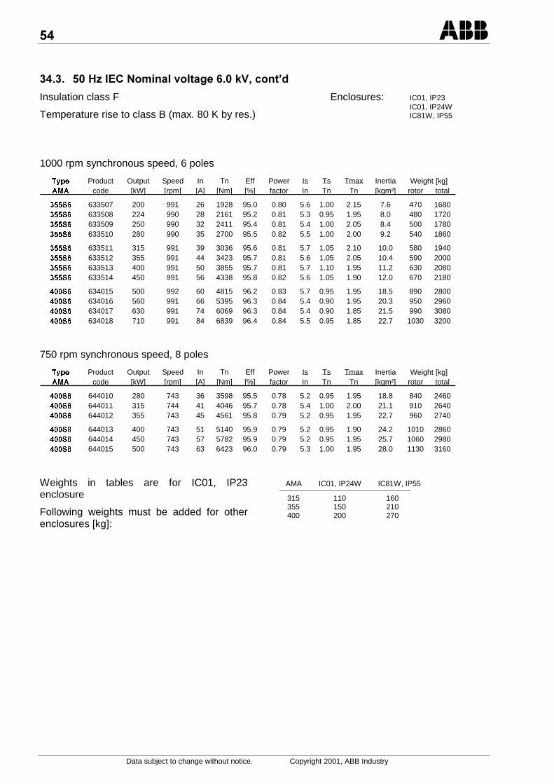
Data subject to change without notice. Copyright 2001, ABB Industry
%% )>/.&*$*,%@=8E
Insulation class F
Temperature rise to class B (max. 80 K by res.)
Enclosures: IC01, IP23IC01, IP24WIC81W, IP55
1000 rpm synchronous speed, 6 poles
7\SH Product Output Speed In Tn Eff Power Is Ts Tmax Inertia$0$ code [kW] [rpm] [A] [Nm] [%] factor In Tn Tn [kgm²] rotor total
6 633507 200 991 26 1928 95.0 0.80 5.6 1.00 2.15 7.6 470 16806 633508 224 990 28 2161 95.2 0.81 5.3 0.95 1.95 8.0 480 17206 633509 250 990 32 2411 95.4 0.81 5.4 1.00 2.05 8.4 500 17806 633510 280 990 35 2700 95.5 0.82 5.5 1.00 2.00 9.2 540 1860
6 633511 315 991 39 3036 95.6 0.81 5.7 1.05 2.10 10.0 580 19406 633512 355 991 44 3423 95.7 0.81 5.6 1.05 2.05 10.4 590 20006 633513 400 991 50 3855 95.7 0.81 5.7 1.10 1.95 11.2 630 20806 633514 450 991 56 4338 95.8 0.82 5.6 1.05 1.90 12.0 670 2180
6 634015 500 992 60 4815 96.2 0.83 5.7 0.95 1.95 18.5 890 28006 634016 560 991 66 5395 96.3 0.84 5.4 0.90 1.95 20.3 950 29606 634017 630 991 74 6069 96.3 0.84 5.4 0.90 1.85 21.5 990 30806 634018 710 991 84 6839 96.4 0.84 5.5 0.95 1.85 22.7 1030 3200
Weight [kg]
750 rpm synchronous speed, 8 poles
7\SH Product Output Speed In Tn Eff Power Is Ts Tmax Inertia$0$ code [kW] [rpm] [A] [Nm] [%] factor In Tn Tn [kgm²] rotor total
6 644010 280 743 36 3598 95.5 0.78 5.2 0.95 1.95 18.8 840 24606 644011 315 744 41 4046 95.7 0.78 5.4 1.00 2.00 21.1 910 26406 644012 355 743 45 4561 95.8 0.79 5.2 0.95 1.95 22.7 960 2740
6 644013 400 743 51 5140 95.9 0.79 5.2 0.95 1.90 24.2 1010 28606 644014 450 743 57 5782 95.9 0.79 5.2 0.95 1.95 25.7 1060 29806 644015 500 743 63 6423 96.0 0.79 5.3 1.00 1.95 28.0 1130 3160
Weight [kg]
Weights in tables are for IC01, IP23enclosure
Following weights must be added for otherenclosures [kg]:
AMA IC01, IP24W IC81W, IP55
315 110 160355 150 210400 200 270
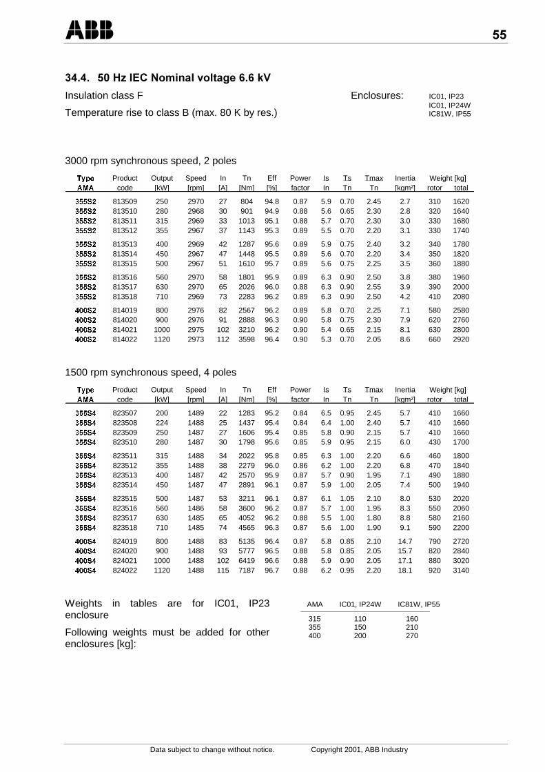
Data subject to change without notice. Copyright 2001, ABB Industry
%% )>/.&*$*,%,@=
Insulation class F
Temperature rise to class B (max. 80 K by res.)
Enclosures: IC01, IP23IC01, IP24WIC81W, IP55
3000 rpm synchronous speed, 2 poles
7\SH Product Output Speed In Tn Eff Power Is Ts Tmax Inertia$0$ code [kW] [rpm] [A] [Nm] [%] factor In Tn Tn [kgm²] rotor total
6 813509 250 2970 27 804 94.8 0.87 5.9 0.70 2.45 2.7 310 16206 813510 280 2968 30 901 94.9 0.88 5.6 0.65 2.30 2.8 320 16406 813511 315 2969 33 1013 95.1 0.88 5.7 0.70 2.30 3.0 330 16806 813512 355 2967 37 1143 95.3 0.89 5.5 0.70 2.20 3.1 330 1740
6 813513 400 2969 42 1287 95.6 0.89 5.9 0.75 2.40 3.2 340 17806 813514 450 2967 47 1448 95.5 0.89 5.6 0.70 2.20 3.4 350 18206 813515 500 2967 51 1610 95.7 0.89 5.6 0.75 2.25 3.5 360 1880
6 813516 560 2970 58 1801 95.9 0.89 6.3 0.90 2.50 3.8 380 19606 813517 630 2970 65 2026 96.0 0.88 6.3 0.90 2.55 3.9 390 20006 813518 710 2969 73 2283 96.2 0.89 6.3 0.90 2.50 4.2 410 2080
6 814019 800 2976 82 2567 96.2 0.89 5.8 0.70 2.25 7.1 580 25806 814020 900 2976 91 2888 96.3 0.90 5.8 0.75 2.30 7.9 620 27606 814021 1000 2975 102 3210 96.2 0.90 5.4 0.65 2.15 8.1 630 28006 814022 1120 2973 112 3598 96.4 0.90 5.3 0.70 2.05 8.6 660 2920
Weight [kg]
1500 rpm synchronous speed, 4 poles
7\SH Product Output Speed In Tn Eff Power Is Ts Tmax Inertia$0$ code [kW] [rpm] [A] [Nm] [%] factor In Tn Tn [kgm²] rotor total
6 823507 200 1489 22 1283 95.2 0.84 6.5 0.95 2.45 5.7 410 16606 823508 224 1488 25 1437 95.4 0.84 6.4 1.00 2.40 5.7 410 16606 823509 250 1487 27 1606 95.4 0.85 5.8 0.90 2.15 5.7 410 16606 823510 280 1487 30 1798 95.6 0.85 5.9 0.95 2.15 6.0 430 1700
6 823511 315 1488 34 2022 95.8 0.85 6.3 1.00 2.20 6.6 460 18006 823512 355 1488 38 2279 96.0 0.86 6.2 1.00 2.20 6.8 470 18406 823513 400 1487 42 2570 95.9 0.87 5.7 0.90 1.95 7.1 490 18806 823514 450 1487 47 2891 96.1 0.87 5.9 1.00 2.05 7.4 500 1940
6 823515 500 1487 53 3211 96.1 0.87 6.1 1.05 2.10 8.0 530 20206 823516 560 1486 58 3600 96.2 0.87 5.7 1.00 1.95 8.3 550 20606 823517 630 1485 65 4052 96.2 0.88 5.5 1.00 1.80 8.8 580 21606 823518 710 1485 74 4565 96.3 0.87 5.6 1.00 1.90 9.1 590 2200
6 824019 800 1488 83 5135 96.4 0.87 5.8 0.85 2.10 14.7 790 27206 824020 900 1488 93 5777 96.5 0.88 5.8 0.85 2.05 15.7 820 28406 824021 1000 1488 102 6419 96.6 0.88 5.9 0.90 2.05 17.1 880 30206 824022 1120 1488 115 7187 96.7 0.88 6.2 0.95 2.20 18.1 920 3140
Weight [kg]
Weights in tables are for IC01, IP23enclosure
Following weights must be added for otherenclosures [kg]:
AMA IC01, IP24W IC81W, IP55
315 110 160355 150 210400 200 270
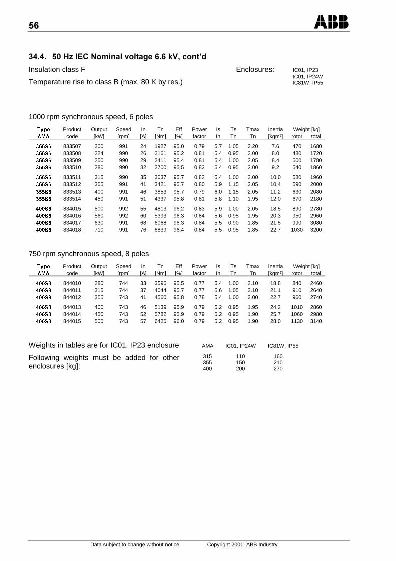
,
Data subject to change without notice. Copyright 2001, ABB Industry
%% )>/.&*$*,%,@=8E
Insulation class F
Temperature rise to class B (max. 80 K by res.)
Enclosures: IC01, IP23IC01, IP24WIC81W, IP55
1000 rpm synchronous speed, 6 poles
7\SH Product Output Speed In Tn Eff Power Is Ts Tmax Inertia$0$ code [kW] [rpm] [A] [Nm] [%] factor In Tn Tn [kgm²] rotor total
6 833507 200 991 24 1927 95.0 0.79 5.7 1.05 2.20 7.6 470 16806 833508 224 990 26 2161 95.2 0.81 5.4 0.95 2.00 8.0 480 17206 833509 250 990 29 2411 95.4 0.81 5.4 1.00 2.05 8.4 500 17806 833510 280 990 32 2700 95.5 0.82 5.4 0.95 2.00 9.2 540 1860
6 833511 315 990 35 3037 95.7 0.82 5.4 1.00 2.00 10.0 580 19606 833512 355 991 41 3421 95.7 0.80 5.9 1.15 2.05 10.4 590 20006 833513 400 991 46 3853 95.7 0.79 6.0 1.15 2.05 11.2 630 20806 833514 450 991 51 4337 95.8 0.81 5.8 1.10 1.95 12.0 670 2180
6 834015 500 992 55 4813 96.2 0.83 5.9 1.00 2.05 18.5 890 27806 834016 560 992 60 5393 96.3 0.84 5.6 0.95 1.95 20.3 950 29606 834017 630 991 68 6068 96.3 0.84 5.5 0.90 1.85 21.5 990 30806 834018 710 991 76 6839 96.4 0.84 5.5 0.95 1.85 22.7 1030 3200
Weight [kg]
750 rpm synchronous speed, 8 poles
7\SH Product Output Speed In Tn Eff Power Is Ts Tmax Inertia$0$ code [kW] [rpm] [A] [Nm] [%] factor In Tn Tn [kgm²] rotor total
6 844010 280 744 33 3596 95.5 0.77 5.4 1.00 2.10 18.8 840 24606 844011 315 744 37 4044 95.7 0.77 5.6 1.05 2.10 21.1 910 26406 844012 355 743 41 4560 95.8 0.78 5.4 1.00 2.00 22.7 960 2740
6 844013 400 743 46 5139 95.9 0.79 5.2 0.95 1.95 24.2 1010 28606 844014 450 743 52 5782 95.9 0.79 5.2 0.95 1.90 25.7 1060 29806 844015 500 743 57 6425 96.0 0.79 5.2 0.95 1.90 28.0 1130 3140
Weight [kg]
Weights in tables are for IC01, IP23 enclosure
Following weights must be added for otherenclosures [kg]:
AMA IC01, IP24W IC81W, IP55
315 110 160355 150 210400 200 270
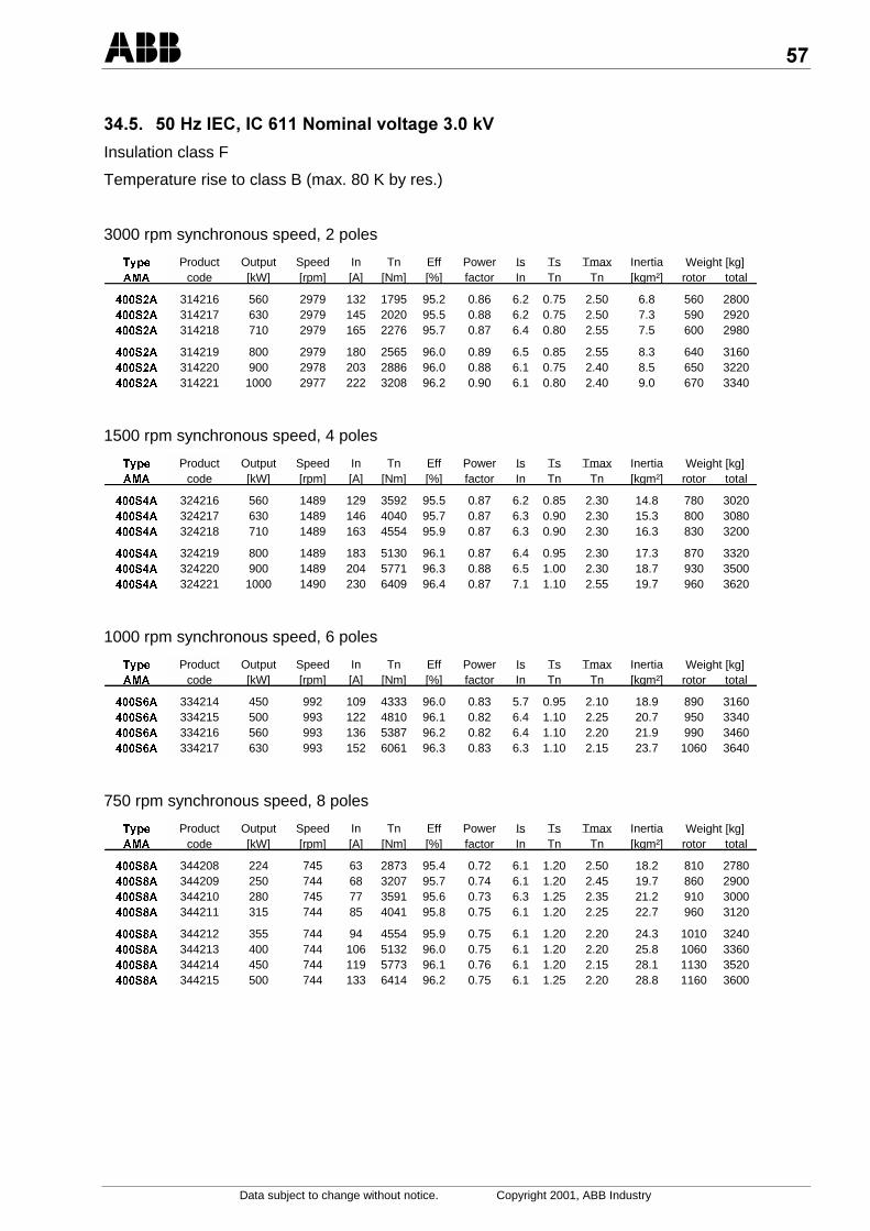
;
Data subject to change without notice. Copyright 2001, ABB Industry
%% )>/.8.,&*$*%@=
Insulation class F
Temperature rise to class B (max. 80 K by res.)
3000 rpm synchronous speed, 2 poles
7\SH Product Output Speed In Tn Eff Power Is Ts Tmax Inertia$0$ code [kW] [rpm] [A] [Nm] [%] factor In Tn Tn [kgm²] rotor total
6$ 314216 560 2979 132 1795 95.2 0.86 6.2 0.75 2.50 6.8 560 28006$ 314217 630 2979 145 2020 95.5 0.88 6.2 0.75 2.50 7.3 590 29206$ 314218 710 2979 165 2276 95.7 0.87 6.4 0.80 2.55 7.5 600 2980
6$ 314219 800 2979 180 2565 96.0 0.89 6.5 0.85 2.55 8.3 640 31606$ 314220 900 2978 203 2886 96.0 0.88 6.1 0.75 2.40 8.5 650 32206$ 314221 1000 2977 222 3208 96.2 0.90 6.1 0.80 2.40 9.0 670 3340
Weight [kg]
1500 rpm synchronous speed, 4 poles
7\SH Product Output Speed In Tn Eff Power Is Ts Tmax Inertia$0$ code [kW] [rpm] [A] [Nm] [%] factor In Tn Tn [kgm²] rotor total
6$ 324216 560 1489 129 3592 95.5 0.87 6.2 0.85 2.30 14.8 780 30206$ 324217 630 1489 146 4040 95.7 0.87 6.3 0.90 2.30 15.3 800 30806$ 324218 710 1489 163 4554 95.9 0.87 6.3 0.90 2.30 16.3 830 3200
6$ 324219 800 1489 183 5130 96.1 0.87 6.4 0.95 2.30 17.3 870 33206$ 324220 900 1489 204 5771 96.3 0.88 6.5 1.00 2.30 18.7 930 35006$ 324221 1000 1490 230 6409 96.4 0.87 7.1 1.10 2.55 19.7 960 3620
Weight [kg]
1000 rpm synchronous speed, 6 poles
7\SH Product Output Speed In Tn Eff Power Is Ts Tmax Inertia$0$ code [kW] [rpm] [A] [Nm] [%] factor In Tn Tn [kgm²] rotor total
6$ 334214 450 992 109 4333 96.0 0.83 5.7 0.95 2.10 18.9 890 31606$ 334215 500 993 122 4810 96.1 0.82 6.4 1.10 2.25 20.7 950 33406$ 334216 560 993 136 5387 96.2 0.82 6.4 1.10 2.20 21.9 990 34606$ 334217 630 993 152 6061 96.3 0.83 6.3 1.10 2.15 23.7 1060 3640
Weight [kg]
750 rpm synchronous speed, 8 poles
7\SH Product Output Speed In Tn Eff Power Is Ts Tmax Inertia$0$ code [kW] [rpm] [A] [Nm] [%] factor In Tn Tn [kgm²] rotor total
6$ 344208 224 745 63 2873 95.4 0.72 6.1 1.20 2.50 18.2 810 27806$ 344209 250 744 68 3207 95.7 0.74 6.1 1.20 2.45 19.7 860 29006$ 344210 280 745 77 3591 95.6 0.73 6.3 1.25 2.35 21.2 910 30006$ 344211 315 744 85 4041 95.8 0.75 6.1 1.20 2.25 22.7 960 3120
6$ 344212 355 744 94 4554 95.9 0.75 6.1 1.20 2.20 24.3 1010 32406$ 344213 400 744 106 5132 96.0 0.75 6.1 1.20 2.20 25.8 1060 33606$ 344214 450 744 119 5773 96.1 0.76 6.1 1.20 2.15 28.1 1130 35206$ 344215 500 744 133 6414 96.2 0.75 6.1 1.25 2.20 28.8 1160 3600
Weight [kg]
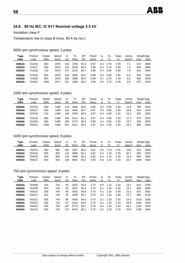
:
Data subject to change without notice. Copyright 2001, ABB Industry
%,% )>/.8.,&*$*%@=
Insulation class F
Temperature rise to class B (max. 80 K by res.)
3000 rpm synchronous speed, 2 poles
7\SH Product Output Speed In Tn Eff Power Is Ts Tmax Inertia$0$ code [kW] [rpm] [A] [Nm] [%] factor In Tn Tn [kgm²] rotor total
6$ 714216 560 2979 118 1795 95.4 0.87 6.4 0.75 2.55 7.1 570 28806$ 714217 630 2979 130 2020 95.5 0.88 6.3 0.75 2.55 7.5 600 29806$ 714218 710 2979 147 2276 95.7 0.88 6.4 0.80 2.55 7.8 610 3040
6$ 714219 800 2979 164 2565 96.0 0.89 6.5 0.80 2.55 8.3 640 31606$ 714220 900 2978 185 2886 96.0 0.89 6.1 0.75 2.40 8.5 650 32006$ 714221 1000 2977 201 3208 96.2 0.90 6.0 0.75 2.35 9.0 670 3340
Weight [kg]
1500 rpm synchronous speed, 4 poles
7\SH Product Output Speed In Tn Eff Power Is Ts Tmax Inertia$0$ code [kW] [rpm] [A] [Nm] [%] factor In Tn Tn [kgm²] rotor total
6$ 724216 560 1489 119 3590 95.5 0.86 6.5 0.90 2.40 14.8 780 30206$ 724217 630 1489 131 4040 95.7 0.87 6.3 0.90 2.30 15.8 810 31406$ 724218 710 1489 149 4553 95.9 0.87 6.4 0.95 2.30 16.3 830 3200
6$ 724219 800 1489 166 5131 96.1 0.87 6.4 0.95 2.30 17.3 870 33206$ 724220 900 1489 185 5772 96.3 0.88 6.4 0.95 2.25 18.7 930 35006$ 724221 1000 1490 207 6411 96.4 0.87 6.8 1.05 2.45 19.7 960 3620
Weight [kg]
1000 rpm synchronous speed, 6 poles
7\SH Product Output Speed In Tn Eff Power Is Ts Tmax Inertia$0$ code [kW] [rpm] [A] [Nm] [%] factor In Tn Tn [kgm²] rotor total
6$ 734214 450 993 102 4327 96.0 0.81 6.5 1.10 2.35 19.5 910 32006$ 734215 500 993 112 4809 96.1 0.81 6.4 1.10 2.25 20.7 950 33206$ 734216 560 993 124 5386 96.2 0.82 6.5 1.15 2.25 21.9 990 34606$ 734217 630 993 138 6061 96.3 0.83 6.3 1.10 2.15 23.7 1060 3620
Weight [kg]
750 rpm synchronous speed, 8 poles
7\SH Product Output Speed In Tn Eff Power Is Ts Tmax Inertia$0$ code [kW] [rpm] [A] [Nm] [%] factor In Tn Tn [kgm²] rotor total
6$ 744208 224 744 56 2874 95.4 0.73 6.0 1.15 2.40 18.2 810 27806$ 744209 250 745 62 3207 95.6 0.73 6.1 1.20 2.45 19.7 860 29006$ 744210 280 744 69 3592 95.8 0.75 6.1 1.20 2.40 21.2 910 30206$ 744211 315 745 78 4040 95.7 0.74 6.3 1.25 2.30 22.7 960 3120
6$ 744212 355 744 86 4554 95.9 0.75 6.1 1.20 2.25 24.3 1010 32406$ 744213 400 744 97 5132 95.9 0.75 6.1 1.20 2.20 25.8 1060 33406$ 744214 450 744 107 5774 96.1 0.76 6.0 1.20 2.10 28.1 1130 35206$ 744215 500 745 121 6413 96.1 0.75 6.2 1.25 2.25 29.6 1180 3640
Weight [kg]

-
Data subject to change without notice. Copyright 2001, ABB Industry
%;% )>/.8.,&*$*,%@=
Insulation class F
Temperature rise to class B (max. 80 K by res.)
3000 rpm synchronous speed, 2 poles
7\SH Product Output Speed In Tn Eff Power Is Ts Tmax Inertia$0$ code [kW] [rpm] [A] [Nm] [%] factor In Tn Tn [kgm²] rotor total
6$ 614216 560 2978 64 1796 95.3 0.88 6.2 0.75 2.50 7.1 570 28606$ 614217 630 2978 72 2020 95.5 0.89 6.2 0.75 2.50 7.5 600 29606$ 614218 710 2979 81 2276 95.7 0.88 6.4 0.80 2.50 7.8 610 3020
6$ 614219 800 2979 89 2565 96.0 0.90 6.5 0.80 2.55 8.5 650 32006$ 614220 900 2977 101 2887 95.9 0.89 6.0 0.75 2.40 8.8 660 32606$ 614221 1000 2977 110 3208 96.2 0.90 6.0 0.80 2.35 9.2 690 3380
Weight [kg]
1500 rpm synchronous speed, 4 poles
7\SH Product Output Speed In Tn Eff Power Is Ts Tmax Inertia$0$ code [kW] [rpm] [A] [Nm] [%] factor In Tn Tn [kgm²] rotor total
6$ 624216 560 1489 65 3592 95.5 0.87 6.2 0.85 2.30 14.8 780 30006$ 624217 630 1489 73 4040 95.7 0.87 6.4 0.95 2.35 15.3 800 30806$ 624218 710 1489 82 4554 95.9 0.87 6.4 0.95 2.30 16.3 830 3180
6$ 624219 800 1489 92 5130 96.1 0.87 6.5 1.00 2.35 17.3 870 33006$ 624220 900 1489 102 5771 96.3 0.88 6.6 1.00 2.40 18.7 930 34806$ 624221 1000 1490 115 6409 96.4 0.87 7.0 1.10 2.55 19.7 960 3600
Weight [kg]
1000 rpm synchronous speed, 6 poles
7\SH Product Output Speed In Tn Eff Power Is Ts Tmax Inertia$0$ code [kW] [rpm] [A] [Nm] [%] factor In Tn Tn [kgm²] rotor total
6$ 634214 450 993 55 4329 96.0 0.83 6.2 1.05 2.20 20.1 930 32606$ 634215 500 992 60 4812 96.1 0.84 6.0 1.00 2.15 21.9 990 34206$ 634216 560 992 67 5389 96.2 0.84 6.0 1.00 2.10 23.1 1040 35406$ 634217 630 993 75 6062 96.3 0.83 6.1 1.05 2.10 24.3 1080 3660
Weight [kg]
750 rpm synchronous speed, 8 poles
7\SH Product Output Speed In Tn Eff Power Is Ts Tmax Inertia$0$ code [kW] [rpm] [A] [Nm] [%] factor In Tn Tn [kgm²] rotor total
6$ 644209 250 744 33 3209 95.4 0.77 5.7 1.05 2.15 20.4 890 29206$ 644210 280 744 37 3593 95.6 0.77 5.9 1.10 2.25 22.7 960 31006$ 644211 315 744 41 4043 95.7 0.77 5.8 1.10 2.20 24.3 1010 3200
6$ 644212 355 744 46 4557 95.8 0.78 5.7 1.05 2.15 25.8 1060 33206$ 644213 400 744 52 5134 95.9 0.78 5.8 1.10 2.15 27.3 1110 34406$ 644214 450 744 58 5775 96.0 0.78 5.8 1.10 2.15 29.6 1180 3620
Weight [kg]

,
Data subject to change without notice. Copyright 2001, ABB Industry
%:% )>/.8.,&*$*,%,@=
Insulation class F
Temperature rise to class B (max. 80 K by res.)
3000 rpm synchronous speed, 2 poles
7\SH Product Output Speed In Tn Eff Power Is Ts Tmax Inertia$0$ code [kW] [rpm] [A] [Nm] [%] factor In Tn Tn [kgm²] rotor total
6$ 814216 560 2979 58 1795 95.4 0.89 6.3 0.75 2.55 7.3 590 29206$ 814217 630 2979 65 2020 95.5 0.89 6.4 0.80 2.60 7.5 600 29606$ 814218 710 2979 74 2276 95.7 0.88 6.5 0.80 2.55 7.8 610 3020
6$ 814219 800 2979 81 2565 96.0 0.90 6.5 0.80 2.55 8.5 650 32006$ 814220 900 2977 92 2887 95.9 0.89 6.0 0.75 2.40 8.8 660 32406$ 814221 1000 2976 100 3209 96.1 0.90 5.9 0.75 2.30 9.2 690 3360
Weight [kg]
1500 rpm synchronous speed, 4 poles
7\SH Product Output Speed In Tn Eff Power Is Ts Tmax Inertia$0$ code [kW] [rpm] [A] [Nm] [%] factor In Tn Tn [kgm²] rotor total
6$ 824216 560 1489 60 3591 95.5 0.86 6.5 0.90 2.40 14.8 780 30006$ 824217 630 1489 66 4040 95.7 0.88 6.3 0.90 2.30 15.8 810 31206$ 824218 710 1489 75 4553 95.9 0.87 6.5 0.95 2.35 16.3 830 3180
6$ 824219 800 1489 83 5130 96.1 0.87 6.5 1.00 2.35 17.3 870 33006$ 824220 900 1489 93 5772 96.3 0.88 6.5 1.00 2.30 18.7 930 34806$ 824221 1000 1490 104 6411 96.4 0.87 6.9 1.10 2.50 19.7 960 3600
Weight [kg]
1000 rpm synchronous speed, 6 poles
7\SH Product Output Speed In Tn Eff Power Is Ts Tmax Inertia$0$ code [kW] [rpm] [A] [Nm] [%] factor In Tn Tn [kgm²] rotor total
6$ 834214 450 993 50 4328 96.0 0.82 6.4 1.10 2.30 20.1 930 32406$ 834215 500 993 55 4811 96.1 0.83 6.2 1.05 2.15 21.9 990 34206$ 834216 560 993 61 5388 96.2 0.83 6.1 1.05 2.10 23.1 1040 35406$ 834217 630 993 68 6062 96.3 0.83 6.1 1.05 2.10 24.3 1080 3660
Weight [kg]
750 rpm synchronous speed, 8 poles
7\SH Product Output Speed In Tn Eff Power Is Ts Tmax Inertia$0$ code [kW] [rpm] [A] [Nm] [%] factor In Tn Tn [kgm²] rotor total
6$ 844209 250 744 31 3208 95.3 0.76 6.0 1.15 2.35 20.4 890 29206$ 844210 280 745 34 3591 95.5 0.76 6.1 1.15 2.40 22.7 960 31006$ 844211 315 744 38 4042 95.7 0.77 5.9 1.10 2.25 24.3 1010 3200
6$ 844212 355 744 42 4556 95.8 0.77 5.8 1.10 2.20 25.8 1060 33206$ 844213 400 744 47 5134 95.9 0.78 5.8 1.10 2.15 27.3 1110 34406$ 844214 450 744 52 5776 96.0 0.78 5.7 1.10 2.10 29.6 1180 3600
Weight [kg]

,
Data subject to change without notice. Copyright 2001, ABB Industry
&/(
Accelerometer ......................................................................19Accessories ..........................................................................13Air filters ...............................................................................15Altitude ...................................................................................8Ambient temperature ..............................................................8Antifriction bearings ..........................................................9, 10Axial forces.....................................................................10, 11
Balancing................................................................................5Bearing accessories .............................................................20Bearing insulation .................................................................20Bearings .................................................................................9Bently Nevada ......................................................................19
Class I Division 2 ......................................................3, 5, 6, 12Class I Zone 2 ....................................................................3, 5Class II Division 2 .........................................................3, 5, 12Colour.............................................................................13, 22Conduit box ..............................................................12, 13, 21Constant level oiler ...............................................................21Control and protective equipment ...................................15, 17Cooling ...................................................................................5Corrosion protection .............................................................13
Differential pressure switch...................................................15Dimension drawings .............................................................24Direction of rotation.........................................................3, 5, 7Documentation ...............................................................14, 23
Enclosures..............................................................................5End float ...........................................................................5, 11
#
Foundation............................................................................16Foundation studs ..................................................................16Frame.....................................................................................5
/
Grease..............................................................................9, 10Grease box...........................................................................21
Hazardous location .................................................................5
+
IC01, IP23 ..............................................................................5IC01, IP24W ...........................................................................6IC611, IP55 ............................................................................6IC81W, IP55...........................................................................6INPRO/SEAL........................................................................20Insulation ................................................................................7Insulation class.......................................................................5
0
Jacking screws .......................................................................5
*
Leakage detector..................................................................15
Lifting lugs.............................................................................. 5Load inertia .......................................................................... 45Low noise............................................................................. 22Lubrication plate..................................................................... 9
Maintenance ........................................................................ 11Mounting ................................................................................ 7
!
ODP....................................................................................... 5Optional accessories............................................................ 15Ordering information .............................................................. 3
Packing.......................................................................... 13, 23Painting.......................................................................... 13, 22Protection......................................................................... 9, 10Pulse encoders .................................................................... 20
Radial forces .................................................................... 9, 10Rating lists ........................................................................... 45Rating plate.......................................................................... 13Relubrication .................................................................... 9, 10Robert Shaw ........................................................................ 18Rotor ...................................................................................... 8Rotor cage ............................................................................. 5
$
Seals.................................................................................... 20Shaft ...................................................................................... 8Shaft end ............................................................................... 5Shims................................................................................... 16Sleeve bearings ................................................................... 11Sole plates ........................................................................... 16Sound level ...................................................................... 7, 22Space heaters................................................................ 15, 20Special colour shade............................................................ 22Special constructions ........................................................... 17SPM........................................................................... 9, 10, 19Starting capacity .................................................................. 45
TACONITE........................................................................... 20TEAAC................................................................................... 6Temperature control....................................................... 15, 17Temperature rise.................................................................... 5Terminal box .................................................................. 12, 21Testing........................................................................... 13, 15TEWAC.................................................................................. 6Thermocouples .............................................................. 17, 18Thermometers................................................................ 17, 18Transmitters......................................................................... 18Type designation.................................................................... 3
1
Velocity transducers............................................................. 19Vibraswitch........................................................................... 18Vibration................................................................................. 8Vibration monitoring ............................................................. 18Windings................................................................................ 7VPI..................................................................................... 5, 7WP-I....................................................................................... 5WP-II...................................................................................... 6

3BFP 001 230 R0101 REV C06/01
For more detailed information, please contact your local ABB representative
ABB Industry OyInduction MachinesP.O. Box 18600381 Helsinki FINLANDTel. +358 10 22 2000Fax +358 10 22 22544www.abb.com/motors&drives