Product Data Sheet - MTS Sensors Sheet SENSORS ® Document Part ... The system manager (e.g. TwinCAT...
12
Model RH Rod-style position sensor Model RP Profile-style position sensor Temposonics ® Magnetostrictive, Absolute, Non-contact Linear-Position Sensors R-Series Models RP and RH EtherCAT ® Industrial Ethernet Interface Data Sheet SENSO RS ® Document Part Number 551074 Revision B All specifications are subject to change. Contact MTS for specifications and engineering drawings that are critical to your application. Drawings contained in this document are for reference only. Go to http://www.mtssensors.com for the latest support documentation and related media. Time-based Magnetostrictive position sensing principle Movable position magnet Magnetic field from position magnet Interaction of magnetic fields causes waveguide to generate a strain pulse Magnetic field encompasses entire waveguide - generated by the interrogation pulse Bias magnet Strain-Pulse detector Interrogation Return wire Waveguide Benefits of Magnetostriction Temposonics linear-position sensors use the time-based magneto- strictive position sensing principle developed by MTS. Within the sensing element, a sonic-strain pulse is induced in a specially designed magnetostrictive waveguide by the momentary interaction of two magnetic fields. One field comes from a movable permanent magnet that passes along the outside of the sensor. The other field comes from an “interrogation” current pulse applied along the waveguide. The resulting strain pulse travels at sonic speed along the waveguide and is detected at the head of the sensing element. The position of the magnet is determined with high precision and speed by accurately measuring the elapsed time between the applica- tion of the interrogation pulse and the arrival of the resulting strain pulse with a high-speed counter. The elapsed time measurement is directly proportional to the position of the permanent magnet and is an absolute value. Therefore, the sensor's output signal corresponds to absolute position, instead of incremental, and never requires recalibration or re-homing after a power loss. Absolute, non-contact sensing eliminates wear, and guarantees the best durability and output repeatability. FEATURES Linear, Absolute Measurement LEDs For Sensor Diagnostics Superior Accuracy, Resolution down to 1 µm Non-Contact Sensing Technology Linearity Deviation Less Than 0.01% Repeatability Within 0.001% Direct EtherCAT Interface, Position + Velocity 100 µs Position / Velocity Update Time, Regardless of Overall Stroke Length BENEFITS Rugged Industrial Sensor Position + Velocity Measurements For Up to 20 Magnets APPLICATIONS Continuous Operation In Harsh Industrial Conditions High Pressure Conditions For Accurate, High-Speed, Simultaneous Multi-Position and Velocity Measurements TYPICAL INDUSTRIES Factory Automation Fluid Power Plastic Injection and Blow Molding Material Handling and Packaging EtherCAT ® is a registered trademark and patented technology licenced by Beckhoff Automation GmbH, Germany
Transcript of Product Data Sheet - MTS Sensors Sheet SENSORS ® Document Part ... The system manager (e.g. TwinCAT...

Model RH Rod-style position sensorModel RP Profile-style position sensor
Temposonics®
Magnetostrictive, Absolute, Non-contact
Linear-Position Sensors
R-Series Models RP and RHEtherCAT® Industrial Ethernet Interface
Data Sheet
SENSORS
®
Document Part Number 551074 Revision B
All specifications are subject to change. Contact MTS for specifications and engineering drawings that are critical to your application. Drawings contained in this document are for reference only. Go to http://www.mtssensors.com for the latest support documentation and related media.
Time-based Magnetostrictive position sensing principle
Movable position magnet
Magnetic field from position magnet
Interaction of magnetic fields causes waveguide to generate a strain pulse
Magnetic field encompassesentire waveguide - generated
by the interrogation pulse
Bias magnet
Strain-Pulse detector
InterrogationReturn wire
Waveguide
Benefits of Magnetostriction
Temposonics linear-position sensors use the time-based magneto- strictive position sensing principle developed by MTS. Within the sensing element, a sonic-strain pulse is induced in a specially designed magnetostrictive waveguide by the momentary interaction of two magnetic fields. One field comes from a movable permanent magnet that passes along the outside of the sensor. The other field comes from an “interrogation” current pulse applied along the waveguide. The resulting strain pulse travels at sonic speed along the waveguide and is detected at the head of the sensing element.
The position of the magnet is determined with high precision and speed by accurately measuring the elapsed time between the applica-tion of the interrogation pulse and the arrival of the resulting strain pulse with a high-speed counter. The elapsed time measurement is directly proportional to the position of the permanent magnet and is an absolute value. Therefore, the sensor's output signal corresponds to absolute position, instead of incremental, and never requires recalibration or re-homing after a power loss. Absolute, non-contact sensing eliminates wear, and guarantees the best durability and output repeatability.
FEATURES
� Linear, Absolute Measurement � LEDs For Sensor Diagnostics � Superior Accuracy, Resolution down to 1 µm � Non-Contact Sensing Technology � Linearity Deviation Less Than 0.01% � Repeatability Within 0.001% � Direct EtherCAT Interface, Position + Velocity � 100 µs Position / Velocity Update Time, Regardless of
Overall Stroke Length
BENEFITS
� Rugged Industrial Sensor � Position + Velocity Measurements For Up to 20 Magnets
APPLICATIONS
� Continuous Operation In Harsh Industrial Conditions � High Pressure Conditions � For Accurate, High-Speed, Simultaneous Multi-Position
and Velocity Measurements
TYPICAL INDUSTRIES
� Factory Automation � Fluid Power � Plastic Injection and Blow Molding � Material Handling and Packaging
EtherCAT® is a registered trademark and patented technology licenced byBeckhoff Automation GmbH, Germany
MTS SensorsR-Series Models RP and RH Temposonics® Linear-Position Sensors - EtherCAT® OutputProduct Data Sheet, Document Part No.: 551074 Revision B (EN) 05/2014 2
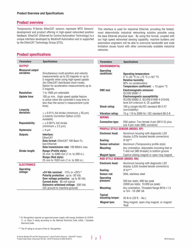
Product specifications
Product overview
Parameters Specifications
OUTPUTMeasured output variables: Simultaneous multi-position and velocity
measurements up to 20 magnets or up to 5 magnets when using high-speed update (for EtherCAT distributed clock mode). Option for acceleration measurements up to 2 magnets.
Resolution: 1 to 1000 µm selectableUpdate time: 100 µs min. (high speed update feature
is active when the controller’s loop time is less than the sensor’s measurement cycle time)
Linearity deviation: < ± 0.01% full stroke (minimum ± 50 µm)
(Linearity Correction Option (LCO) available)
Repeatability: < ± 0.001% full stroke(minimum ± 2.5 µm)
Hysteresis: < 4 µm
Outputs: Interface: EtherCATData format: EtherCAT 100 Base-Tx, fast EthernetData transmission rate: 100 Mbit/s max.
Stroke length: Range (Profile style): 25 mm to 5080 mm (1 in. to 200 in.)Range (Rod style): 25 mm to 7620 mm (1 in. to 300 in.)
ELECTRONICS
Operating voltage: +24 Vdc nominal: -15% or +20%*
Polarity protection: up to -30 VdcOver voltage protection: up to 36 VdcCurrent drain: 80 mA typicalDielectric withstand voltage: 500 Vdc (DC ground to machine ground)
Product Overview and Specifications
Parameters Specifications
ENVIRONMENTAL
Operating conditions: Operating temperature:
0 °C (32 °F) to +75 °C (+167 °F)Relative humidity: 90% no condensationTemperature coefficient: < 15 ppm/ °C
EMC test: Electromagnetic emission: IEC/EN 50081-1Electromagnetic susceptibility: IEC/EN 50082-2, IEC/EN 61000-4-2/3/4/6, level 3/4 criterium A, CE qualified
Shock rating: 100 g (single hit)/IEC standard 68-2-27 (survivability)
Vibration rating: 15 g / 10 to 2000 Hz / IEC standard 68-2-6WIRING
Connection type: D56 option: Two female 4-pin (M12-D) plus one 4-pin male (M8) connector
PROFILE STYLE SENSOR (MODEL RP)
Electronic head: Aluminum housing with diagnostic LED display (LEDs located beside connectors)
Sealing: IP 65**Sensor extrusion: Aluminum (Temposonics profile style)Mounting: Any orientation. Adjustable mounting feet or
T-slot nut (M5 threads) in bottom grooveMagnet types: Captive-sliding magnet or open-ring magnetROD STYLE SENSOR (MODEL RH)
Electronic head: Aluminum housing with diagnostic LED display (LEDs located beside connectors)
Sealing: IP 67**Sensor rod: 304L stainless steelOperating pressure: 350 bar static, 690 bar peak
(5000 psi static, 10,000 psi peak) Mounting: Any orientation. Threaded flange M18 x 1.5
or 3/4 - 16 UNF-3ATypical mounting torque: 45 N-m (33 ft. - lbs.)Magnet tyes: Ring magnet, open-ring magnet, or magnet
float
Temposonics R-Series EtherCAT sensors represent MTS Sensors’ development and product offering in high-speed networked position feedback. EtherCAT (Ethernet for Control Automation Technology) is a unique interface developed by Beckhoff Automation and is supported by the EtherCAT Technology Group (ETG).
This interface is used for industrial Ethernet, providing the fastest, most deterministic industrial networking solution possible using the base Ethernet physical layer. By using this format, coupled with our high speed networked sensing capability, machine builders and automation engineers will be able to overcome bandwidth and node limitation issues found with other commercially available industrial networks.
* UL Recognition requires an approved power supply with energy limitation UL 61010- 1), or Class 2 rating according to the National Electrical Code (USA) / Canadian Electrical Code.
** The IP rating is not part of the UL Recognition.

MTS SensorsR-Series Models RP and RH Temposonics® Linear-Position Sensors - EtherCAT® Output
Product Data Sheet, Document Part No.: 551074 Revision B (EN) 05/20143
EtherCAT Output Options, ProgrammabilityEnhanced Monitoring and Diagnostics
Enhanced monitoring and diagnostics
SENSOR STATUS AND DIAGNOSTIC DISPLAY
Integrated diagnostic LEDs (green/red), located beside sensor connectors (see ‘Figure 1’), pro-vide basic visual monitoring for normal sensor operation and troubleshooting. Diagnostic display LEDs indicate four modes described in ‘Table 1. Diagnostic display indicator modes'
Figure 1. R-Series sensor Integrated diagnostic LEDs
Status LED (Green)
Off:On:Flashing:
InitializingNormal functionVarious flashing codes showdifferent operational status
Error LED (Red)
Off:On:Flashing:
Normal functionmissing magnetSupply voltage beyond limits (high or low)
IN Port LED (Green)
Off:On:Flashing:
No linkLink detectedTraffic
OUT Port LED (Green)
Off:On:Flashing:
No linkLink detectedTraffic
Table 1. Diagnostic display indicator modes
EtherCAT interface
EtherCAT is an open field bus system which is based on Ethernet technology, (IEEE 802.3), with a high data rate and short response time, resulting in very good real-time performance. It is standardized in the IEC/PAS 62407 and is part of the ISO 15745-4 standard. The EtherCAT protocol is also being integrated into the IEC 61158, IEC 61784, and IEC 61800-7 standards.
The Temposonics EtherCAT sensor is connected as a slave device, and as such, fulfils all the requirements of the EtherCAT field bus system. Adding the sensor to an EtherCAT bus system is very easy. The system manager (e.g. TwinCAT from Beckoff Automation) gets all the parameters of the sensor from the XML file, available from the MTS website at http://www.mtssensors.com. There are no adjustments necessary on the sensor itself. For some applications, optimum system performance is obtained using the sensor’s high speed updates, up to 10 kHz, by synchronizing to the EtherCAT’s 'distributed clock mode' (available on the “E101” sensor output option).
Operation modes and output
There are two operation modes available:
E101 - Fast update position and velocity:
• Designed for high-speed motion control• Up to 5 simultaneous magnet measurements• 100 µs update rate, (independent of stroke length)
E102 Multi-magnet position and velocity:
• Designed for gauging systems having many magnet positions• Up to 20 simultaneous magnet measurements• Standard update rates, (stroke length dependent)
When using multiple magnets, the minimum allowed distance between magnets is 75 mm (3 in.) to maintain proper sensor output (see ‘Figure 2’).
Figure 2.
1 to 5 magnet Measurement
1 to 20 magnetMeasurement
M1
Active stroke length
Position / Velocity
M1 M2 M19 M20
75 mm(3 in.) min.
M3
Position / Velocity
M2 M4 M5M3
75 mm(3 in.) min.
Temposonics®
R-Series R®
Temposonics®
R-Series R®
Single to multi-magnet output diagram
LINEARITY CORRECTION OPTION (LCO)
The Linearity Correction Option (LCO) provides improved sensor output accuracy. For most stroke lengths linearity accuracy is improved up to a factor of 5 resulting in deviations from actual position of less than ± 20 µm (0.0008 in.). For stroke lengths over 5000 mm (197 in.), the linearity accuracy is improved up to factor of 10. Selecting the sensor style and magnet is important (both must be matched together). Contact the factory for assistance when designing for the LCO in your application.

MTS SensorsR-Series Models RP and RH Temposonics® Linear-Position Sensors - EtherCAT® OutputProduct Data Sheet, Document Part No.: 551074 Revision B (EN) 05/2014 4
Model RP profile-style sensor dimension references
MODEL RP, PROFILE-STYLE SENSOR WITH CAPTIVE-SLIDING MAGNET Drawing is for reference only, contact applications engineering for tolerance specific information.
49 mm(1.92 in.)
9 mm(0.36 in.)
50 mm (1.97 in.)68 mm (2.68 in.)
5.5 mm(0.21 in.) dia.
M5 or #10 screw
2 mm(0.07 in.)
45 mm(1.77 in.)
12 mm (0.47 in.)
100 mm(3.9 in.)
Stroke length
82 mm (3.2 in.)Dead zone
End of stroke‘Span’ position
Beginning of stroke ‘Null’ position
Mounting foot, moveable(part no.: 400802)
Electronics housing
Captive-sliding magnet
D56integral connector option
19 mm (0.75 in.)
Figure 3. R-Series Model RP Profile-style sensor dimension reference (Shown with the D56 connector option)
MODEL RP, PROFILE-STYLE SENSOR WITH OPEN-RING MAGNET Drawing is for reference only, contact applications engineering for toler-ance specific information.
28 mm(1.10 in.)
Nullzone
Open-ring magnet Style M(part no. 251416-2)
Dead Zone66 mm (2.6 in.)
Stroke lengthNon-ferrous mountingsupport and screws
100 mm(3.9 in.)
19 mm(0.75 in.)
28 mm(1.10 in.)
D56integral connector option
ElectronicsHousing
End of stroke ‘Span’ positionBeginning of stroke ‘Null’ position
Figure 4. R-Series Model RP Profile-style sensor dimension reference (Shown with the D56 connector option)
Model RP Profile-Style SensorSensor Dimension References

MTS SensorsR-Series Models RP and RH Temposonics® Linear-Position Sensors - EtherCAT® Output
Product Data Sheet, Document Part No.: 551074 Revision B (EN) 05/20145
Model RP Profile-Style SensorStandard Magnet Selections
Standard magnet selections (Model RP)
SELECTION OF POSITION MAGNETS (ONE MAGNET INCLUDED WITH MODEL RP SENSOR)
A choice of two magnet mounting configurations are available with the profile-style sensor; A ‘captive-sliding’ magnet, Styles S or V or an ‘open-ring’ magnet, Style M. Captive-sliding magnets utilize slide bearings of special material that reduce friction, and if required, help mitigate dirt build up. The slide bearings are designed to operate dry, requiring no external lubrication or maintenance.
The Style M ‘open-ring’ magnet mounts on the moving machine part and travels just above the sensor’s profile extrusion. The open-ring magnet requires a minimum distance away from ferrous metals to allow proper sensor output. It must be mounted using non-ferrous screws and a non-ferrous support bracket, or utilize a non-ferrous spacer of at least 5 mm (0.2 in.) thickness.
POSITION MAGNET SELECTIONS (Drawing dimensions are for reference only)
Magnet dimensions and mounted magnet dimensions Description Part number
40 mm(1.58 in.)
25 mm(1 in.)
20 mm(0.79 in.)
43 mm(1.69 in.)
14 mm(0.55 in.)
Rotation: Vertical: 18°
Horizontal: 360°
Ball-jointed arm(M5 thread)
Captive-sliding magnet, Style S
For Model RP profile-style sensor252182
40 mm(1.58 in.)
25 mm(1 in.)
9 mm(0.35 in.)
57 mm(2.24 in.)
14 mm(0.55 in.)
Rotation: Vertical: 18°
Ball-jointed arm(M5 thread)
Captive-sliding magnet, Style V
For Model RP profile-style sensor252184
Magnet dimensions and mounted magnet dimensions Description Part number
21 mm(0.81 in.)
25 mm(0.97 in.)14 mm
(0.55 in.)
2 HolesEach 4.3 mm(0.17 in.) dia. on24 mm (0.94 in.) dia.
60°
Open-ring magnet, Style M
I.D.: 13.5 mm (0.53 in.)O.D.: 33 mm (1.3 in.)Thickness: 8 mm (0.31 in.)Operating temperature: - 40 °C to 100 °C
This magnet may influence the sensor performance specifications for some applications.
251416-2
45 mm(1.77 in.)
52 mm(2.05 in.)
36 mm(1.41 in.)
21 mm(0.81 in.)
29 mm(1.14 in.)
Max gap3 mm ± 1 mm(0.12 in. ± 0.04 in.)
Non-ferrous mounting supportand screws
Open-ring magnet Style ‘M’

MTS SensorsR-Series Models RP and RH Temposonics® Linear-Position Sensors - EtherCAT® OutputProduct Data Sheet, Document Part No.: 551074 Revision B (EN) 05/2014 6
Model RP Sensor mountingModel RP profile-style sensor mounting flexible installation in any position!
Temposonics Model RP profile-style sensors offer two basic mounting methods; side grooves for use with mounting feet or a bottom groove that accepts special T-Slot nuts. Both the mounting feet and T-Slot nuts can be positioned along the sensor extrusion to best secure the sensor for each particular application.
Notes:
1. Model RP sensors include two mounting feet (part no. 400802) for sensors stroke lengths up to 1250 mm (50 in.)2. One additional mounting foot is included for stroke lengths over 1250 mm (50 in.) and for each additional 500 mm (20 in.),
thereafter.3. MTS recommends using 10-32 cap screws (customer supplied) at a maximum torque of 44 in. lbs. when fastening mounting feet.
Profile-Style sensor mounting and installation reference Mounting method Part number
(Width = 14.5 mm (0.57 in.)
Mounting feet, standard (304 SS)
Profile-style sensor mounting for sen-sor model RP
400802
10 - 32 Cap screwsRecommended(Customer supplied)
Mounting feet and screws
Profile-style sensor foot installation
See Mounting Feet
part number:400802
T-Slot nut
Nut for mounting model RP sensorM5 thread (Optional, ordered separately)
401602
4 Holes5.3 mm
(0.21 in.) dia.
28 mm(1.1 in.)
9 mm(0.36 in.)
50 mm(1.97 in.)
2 mm(0.08 in.) 68 mm
(2.68 in.)
9 mm(0.36 in.)
Mounting foot and screws
5 mm (0.20 in.)T-Slot nut, M5 threadDetail
M5 Threadedstud and nut
Model RP Profile-Style Sensor Sensor Mounting Reference

MTS SensorsR-Series Models RP and RH Temposonics® Linear-Position Sensors - EtherCAT® Output
Product Data Sheet, Document Part No.: 551074 Revision B (EN) 05/20147
Model RH Rod-Style SensorDimension References
Model RH rod-style sensor dimension reference
The Temposonics R-Series rod-style sensor (Model RH) offers modular construction, flexible mounting configurations, and easy installation. The Model RH sensor is designed for mounting in applications where high pressure conditions exist (5000 psi continuous, 10,000 psi spike) such as inside hydraulic cylinders. The Model RH sensor (see 'Figure 5') may also be mounted externally in many applications.
Stroke-dependent Dead Zones:Stroke length:
25 mm (1 in.) - 5000 mm (197 in.)
5005 mm (197 in.) - 7620 mm (300 in.)
Dead zone:
63.5 mm (2.5 in.)
66 mm (2.6 in.)
MODEL RH, ROD-STYLE SENSOR WITH RING MAGNET (MAGNET ORDERED SEPARATELY) Drawing is for reference only, contact applications engineering for tolerance specific information.
Figure 5. Model RH Rod-style sensor dimension reference (shown with D56 integral connector options
19 mm (0.75 in.)
105 mm (4.1 in.) 51 mm (2 in.)
Beginning of stroke ‘Null’ position End of stroke ‘Span’ position
Electronics housing
Null zoneStroke length
Flat-faced hex flange type ‘S ’
Sensor Rod10 mm (0.39 in.) dia.25 mm
(0.98 in.)
O-RingRing magnet
Dead zone(refer to Notes
‘Stroke dependentdead zones’)
Refer to ‘Table 2’ for(A) Flange threads
D56Integral connector option
)
MODEL RH, ROD-STYLE SENSOR WITH RING MAGNET (MAGNET ORDERED SEPARATELY) Drawing is for reference only, contact applications engineering for tolerance specific information.
Figure 6.
25.4 mm (1 in.)
O-Ring
Beginning of stroke ‘Null’ position
Null
51 mm (2 in.)
Electronicshousing
2.5 mm (0.10 in.)
Raised-faced flange, Type ‘T’Refer to ‘Table 2’
25 mm (0.98 in.)
Ring Magnetpart no.: 201542-2
Refer to ‘Table 2’ (A) Flange Threads
B
C
Refer to ‘Table 2’(B) dimensions and (C) dimensions
D56Integral connector option
Model RH Rod-style sensor dimension reference (Shown with the D56 Integral cable connection type option)
Housing styleFlange type Description (A) Flange threads (B) Dimensions (C) Dimensions
T US customary threads with raised-face flange 3/4" - 16 UNF-3A 1.75 in. 2 in.
S US customary threads with flat-faced flange 3/4" - 16 UNF-3A 1.75 in. 2 in.
M Metric threads with flat-faced flange M18 x 1.5 46 mm 53 mm
Table 2. Model RH Rod-style sensor housing style and flange type references
MTS SensorsR-Series Models RP and RH Temposonics® Linear-Position Sensors - EtherCAT® OutputProduct Data Sheet, Document Part No.: 551074 Revision B (EN) 05/2014 8
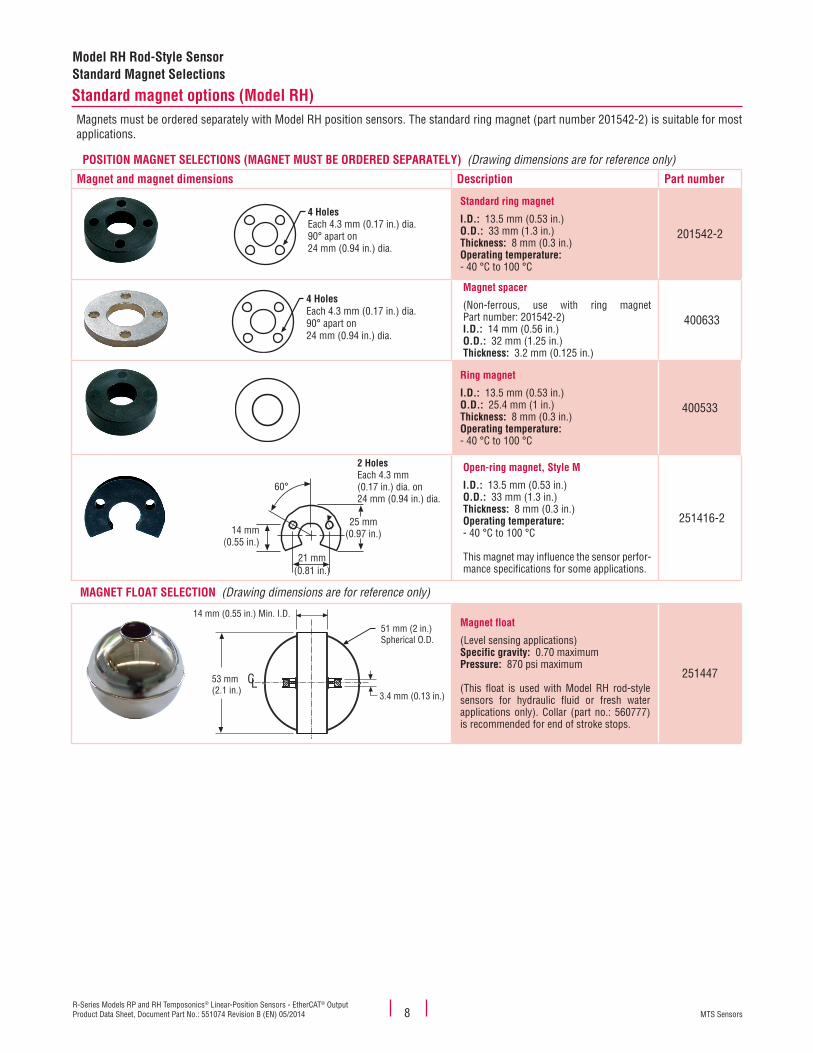
Model RH Rod-Style SensorStandard Magnet Selections
Standard magnet options (Model RH)Magnets must be ordered separately with Model RH position sensors. The standard ring magnet (part number 201542-2) is suitable for most applications.
POSITION MAGNET SELECTIONS (MAGNET MUST BE ORDERED SEPARATELY) (Drawing dimensions are for reference only)
Magnet and magnet dimensions Description Part number
Standard ring magnet
I.D.: 13.5 mm (0.53 in.)O.D.: 33 mm (1.3 in.)Thickness: 8 mm (0.3 in.)Operating temperature: - 40 °C to 100 °C
201542-2
Magnet spacer
(Non-ferrous, use with ring magnet Part number: 201542-2)I.D.: 14 mm (0.56 in.)O.D.: 32 mm (1.25 in.)Thickness: 3.2 mm (0.125 in.)
400633
Ring magnet
I.D.: 13.5 mm (0.53 in.)O.D.: 25.4 mm (1 in.)Thickness: 8 mm (0.3 in.)Operating temperature: - 40 °C to 100 °C
400533
Open-ring magnet, Style M
I.D.: 13.5 mm (0.53 in.)O.D.: 33 mm (1.3 in.)Thickness: 8 mm (0.3 in.)Operating temperature: - 40 °C to 100 °C
This magnet may influence the sensor perfor-mance specifications for some applications.
251416-2
MAGNET FLOAT SELECTION (Drawing dimensions are for reference only)
Magnet float
(Level sensing applications)Specific gravity: 0.70 maximumPressure: 870 psi maximum
(This float is used with Model RH rod-style sensors for hydraulic fluid or fresh water applications only). Collar (part no.: 560777) is recommended for end of stroke stops.
251447
4 HolesEach 4.3 mm (0.17 in.) dia.90° apart on 24 mm (0.94 in.) dia.
4 HolesEach 4.3 mm (0.17 in.) dia.90° apart on 24 mm (0.94 in.) dia.
21 mm(0.81 in.)
25 mm(0.97 in.)14 mm
(0.55 in.)
2 HolesEach 4.3 mm(0.17 in.) dia. on24 mm (0.94 in.) dia.
60°
14 mm (0.55 in.) Min. I.D.
51 mm (2 in.)Spherical O.D.
3.4 mm (0.13 in.)
CL53 mm(2.1 in.)

MTS SensorsR-Series Models RP and RH Temposonics® Linear-Position Sensors - EtherCAT® Output
Product Data Sheet, Document Part No.: 551074 Revision B (EN) 05/20149
Model RH Rod-Style Sensor Mounting Cylinder Installation and Connections
Model RH rod-style sensor mounting
The position magnet requires minimum distances away from ferrous metals to allow proper sensor output. The minimum distance from the front of the magnet to the cylinder end cap is 15 mm (0.6 in.).
The minimum distance from the back of the magnet to the piston head is 3.2 mm (0.125 in.). However, a minimum distance of at least 5 mm (0.197 in.) is preferred for added performance margin. The non-ferrous spacer (part no. 400633), provides this minimum distance when used along with the standard ring magnet (part no.: 201542-2) as shown in Figure 7.
Figure 7.
Non ferrous spacer
Min. 3.2 mm (0.125 in.)
Ring magnet
on fepace
(0.125 in.)
g magnetRing
Nosp
Min. 3.2 mm(0 125 in )
g magnetRing
Cylinder end cap
Piston head
Temposonics ®
R-Series R®
> 15 mm (0.6 in.)
Model RH rod-style mounting
Cylinder installation
When used for direct-stroke measurement in fluid cylinders, the sensor's high pressure, stainless steel rod installs into a bore in the piston head/rod assembly as shown in Figure 8. This method guarantees a long-life and trouble-free operation.
The sensor cartridge can be removed from the flange and rod hous-ing while still installed in the cylinder. This procedure allows quick and easy sensor cartridge replacement, without the loss of hydraulic pressure.
The sensor’s rod housing and flange can remainpermanently installed in the cylinder
Ring magnet
The sensor cartridge, consisting of the electronics housingand sensing element, is easy to replace by removing(2) M4 thread 2.5 mm hex socket head screws
Figure 8. Fluid cylinder installation
(D56) BUS CONNECTOR OPTION
D56 connector option for 'daisy chain' topologies. A separate cable is used for the supply voltage. Unused connectors should be covered by a protective cap (part no.: 370537).
D56Female
4-pin Bus In
D56Female
4-pin Bus Out
D56Male, 4-pin
Input voltage
Connections and wiringBUS CONNECTIONS IN/OUT
43
21
Female, 4-pin (M12-D) Integral connector pin-out as viewed from the end of the sensor
Pin number Cable color Function
1 Yellow Tx+
2 White Rx+
3 Orange Tx-
4 Blue Rx-
INPUT VOLTAGE
34
21
Input voltage, male, 4-pin (M8) integral connector pin-out as viewed from the end of the sensor
Pin number Cable color Supply voltage
1 Brown +24 Vdc (-15/+20%)
2 White No connection
3 Blue DC ground (for supply)
4 Black No connection

MTS SensorsR-Series Models RP and RH Temposonics® Linear-Position Sensors - EtherCAT® OutputProduct Data Sheet, Document Part No.: 551074 Revision B (EN) 05/2014 10
Models RP and RH SensorsOrdering Information, Connector and Cable Assembly Options(D56) CABLE CONNECTOR OPTIONS (Drawing dimensions are for reference only)
Connector and connector dimensions Description Part number
Bus Cable Connector, Male 4-pin (M12), D-coded with insulation displacement technology
370523
Connector, Female 4-pin (M8) and cable with pigtail termination
For 24 Vdc input. Wire gage 4x0.25 mm2 shielded, PUR cable jacket
5 m length = 530066
10 m length = 530096
15 m length = 530093
Connector end cap
(Unused connectors should be covered by this protective cap)
370537
BUS CABLE WITH CONNECTORS (Drawing dimensions are for reference only)
Bus cable and connector assemblies Description Part number
Ethernet cable
2 - Male, (M12) 4-pin connectors
47 mm(1.85 in.)
16 mm(0.63 in.) dia.
1
23
4
Industrial Ethernet Bus Cable, 5 m length (Cat 5e ES)
Assembly Includes two 4-pin (M12) connectors (D-coded) and PUR cable jacket (green)
530064
Ethernet cable
Male, (M12) 4-pin connector
47 mm(1.85 in.)
16 mm(0.63 in.) dia.
1
23
4
M12 x 1
RJ45 Connector
55 mm(2.17 in.)
Industrial Ethernet Bus Cable, 5 m length (Cat 5e ES)
Assembly Includes one RJ45 connector and one 4-pin (M12) connector (D-coded) with PUR cable jacket (green) Cables using the RJ45 connector provide con-venient sensor connection to a PC for setup and programming but are not recommended for factory floor installations.
530065
SW17/ width across flats 17
M12
x1Ø1
9.5 m
m(0.
77 in
.)
52 mm (2.05 in.)
SW13/ width across flats 13
10 mm(0.39 in.)
dia.
M8 x 1
32.5 mm(1.28 in.)

MTS SensorsR-Series Models RP and RH Temposonics® Linear-Position Sensors - EtherCAT® Output
Product Data Sheet, Document Part No.: 551074 Revision B (EN) 05/201411
Models RP and RH SensorsOrdering Information
R D 5 6 1 E 1 0
1 2 3 4 5 6 7 8 9 10 11 12 13 14 15 16 17 18 19
SENSOR MODEL = R 1-2RP = Profile style RH = Hydraulic rod style
HOUSING STYLE = 3
Model RP profile-style sensor (includes one magnet):S = Captive-sliding magnet with ball joint
at top (part no. 252182)V = Captive-sliding magnet with ball
joint at front (part no. 252184)M = Open-ring magnet (part no. 251416-2)
Model RH rod-style sensor (magnet(s) must be ordered separately):T = US customary threads, raised-faced
flange and pressure tube, standardU = Same as option “T”, except uses
fluoroelastomer seals for the electronics housing
B = Sensor cartridge only (no flange or pressure tube, stroke length < 1830 mm (72 in.))
S = US customary threads, flat-faced flange and pressure tube, standard
H = Same as option “S”, except uses fluoroelastomer seals for the electronics housing
M = Metric threads, flat-faced flange and pressure tube, standard
V = Same as option “M”, except uses fluoroelastomer seals for the electronics housing
STROKE LENGTH = 4-8
— — — — M = Millimeters(Encode in 5 mm increments)
Stroke Length Notes:
— — — . — U = Inches and tenths(Encode in 0.1 in. increments)
1. Profile-style sensor (model RP) stroke range = 25 mm (1 in.) - 5080 mm. (200 in.)2. Rod-style sensor (model RH) stroke range = 25 mm (1 in.) - 7620 mm (300 in.)
CONNECTION TYPE = D 5 6 9-11
Integral connector:
D56 = Two 4-pin female (M12-D), plus one 4-pin male (M8)
INPUT VOLTAGE = 1 121 = +24 Vdc (+20% - 15%)
OUTPUT = E 1 0 13-16
E101 = EtherCAT, position and velocity, high speed updates, maximum 5 magnets
E102 = EtherCAT, position and velocity, maximum 20 magnets
E103 = Same as option 'E101' with Linearity Correction Option (LCO)
E104 = Same as option 'E102' with Linearity Correction Option (LCO)
NUMBER OF MAGNETS = Z 17-19
For multi-position measurement only (Order additional magnets separately).
Z — — = Number of magnets for output E101 (range 02 to 05), or for output E102 (range 02 to 20)

Document Part number: 551074 Revision B (EN) 05/2014
MTS, Temposonics and Level Plus are registered trademarks of MTS Systems Corporation. All other trademarks are the property of their respective owners. Printed in USA. Copyright © 2014 MTS Systems Corporation. All Rights Reserved in all media.
All specifications are subject to change. Contact MTS for specifications and engineering drawings that are critical to your application. Drawings contained in this document are for reference only. Go to http://www.mtssensors.com for the latest product information.
LOCA
TION
S
LEGA
L NO
TICE
SUSAMTS Systems CorporationSensors Division3001 Sheldon DriveCary, N.C. 27513, USATel. +1 919 677-0100Fax +1 919 [email protected]
GERMANYMTS Sensor TechnologieGmbH & Co. KGAuf dem Schüffel 958513 Lüdenscheid, GermanyTel. + 49 2351 9587-0Fax + 49 2351 [email protected]
JAPANMTS Sensors Technology Corp.737 Aihara-machi, Machida-shi, Tokyo 194-0211, JapanTel. + 81 42 775-3838Fax + 81 42 775- [email protected]
FRANCEMTS Systems SASZone EUROPARC Bâtiment EXA 1616/18, rue Eugène Dupuis94046 Creteil, FranceTel. + 33 1 58 4390-28Fax + 33 1 58 [email protected]
ITALYMTS Systems Srl.Sensor DivisionVia Diaz,425050 Provaglio d‘Iseo (BS), ItalyTel. + 39 030 988 3819Fax + 39 030 982 [email protected]
CHINAMTS Sensors Room 504, Huajing Commercial Center, No. 188, North Qinzhou Road200233 Shanghai, ChinaTel. +86 21 6485 5800 Fax +86 21 6495 [email protected]