Product Data · Scroll compressor Internal pressure relief valve Internal thermal overload Filter...
20
Product Data 24ABB3**C Comfortt13 Air Conditioner for Coastal Applications with Puronr Refrigerant Carrier’s Air Conditioners with Puronr refrigerant provide a collection of features unmatched by any other family of equipment. The 24ABB has been designed utilizing Carrier’s Puron refrigerant. The environmentally sound refrigerant allows you to make a responsible decision in the protection of the earth’s ozone layer. NOTE: Ratings contained in this document are subject to change at any time. Always refer to the AHRI directory (www.ahridirectory.org) for the most up−to−date ratings information. INDUSTRY LEADING FEATURES / BENEFITS Efficiency S 13 SEER/11 EER S Microtube Technologyt refrigeration system S Indoor air quality accessories available Sound S Sound level as low as 75 dBA Comfort S System supports Thermidistatt or standard thermostat controls Reliability S Puronr refrigerant − environmentally sound, won’t deplete the ozone layer and low lifetime servce cost. S Front−seating service valves S Scroll compressor S Internal pressure relief valve S Internal thermal overload S Filter drier S Balanced refrigeration system for maximum reliability Durability WeatherArmor t protection package: S Solid, durable sheet metal construction S Dense wire coil guard S Baked−on powder paint on all sides ArmorPlate Condenser Coil S Aluminum fin material is pre−coated on both sides with a corrosion protective epoxy phenolic coating. Applications S Long−line − up to 250 feet (76.20 m) total equivalent length, up to 200 feet (60.96 m) condenser above evaporator, or up to 80 ft. (24.38 m) evaporator above condenser (See Longline Guide for more information.) S Low ambient (down to −20_F/−28.9_C)) with accessory kit
Transcript of Product Data · Scroll compressor Internal pressure relief valve Internal thermal overload Filter...

Product Data
24ABB3**CComfort�13 Air Conditioner for Coastal Applicationswith Puron� Refrigerant
Carrier’s Air Conditioners with Puron� refrigerant provide acollection of features unmatched by any other family ofequipment. The 24ABB has been designed utilizing Carrier’sPuron refrigerant. The environmentally sound refrigerant allowsyou to make a responsible decision in the protection of the earth’sozone layer.
NOTE: Ratings contained in this document are subject tochange at any time. Always refer to the AHRI directory(www.ahridirectory.org) for the most up−to−date ratingsinformation.
INDUSTRY LEADING FEATURES / BENEFITSEfficiency
� 13 SEER/11 EER
� Microtube Technology� refrigeration system
� Indoor air quality accessories available
Sound� Sound level as low as 75 dBA
Comfort� System supports Thermidistat� or standard thermostat
controls
Reliability� Puron� refrigerant − environmentally sound, won’t
deplete the ozone layer and low lifetime servce cost.
� Front−seating service valves
� Scroll compressor
� Internal pressure relief valve
� Internal thermal overload
� Filter drier
� Balanced refrigeration system for maximum reliability
DurabilityWeatherArmor� protection package:
� Solid, durable sheet metal construction
� Dense wire coil guard
� Baked−on powder paint on all sides
ArmorPlate Condenser Coil
� Aluminum fin material is pre−coated on both sides witha corrosion protective epoxy phenolic coating.
Applications� Long−line − up to 250 feet (76.20 m) total equivalent
length, up to 200 feet (60.96 m) condenser aboveevaporator, or up to 80 ft. (24.38 m) evaporator abovecondenser (See Longline Guide for more information.)
� Low ambient (down to −20�F/−28.9�C)) withaccessory kit
2
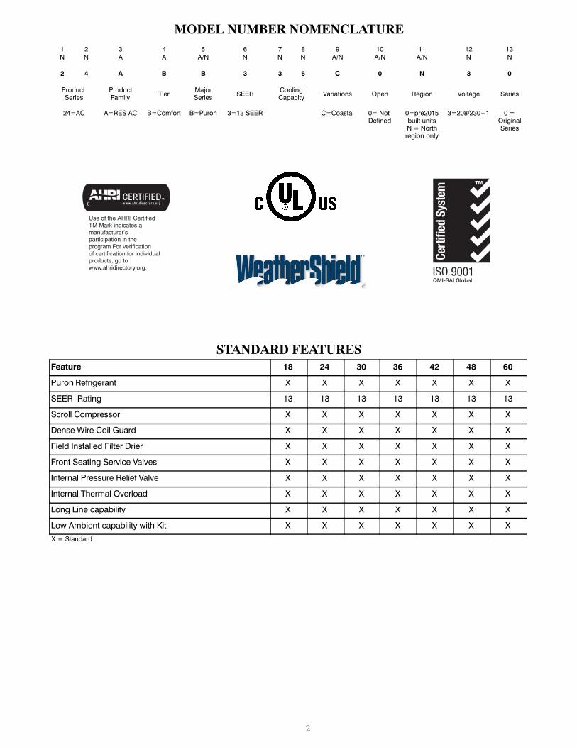
MODEL NUMBER NOMENCLATURE1 2 3 4 5 6 7 8 9 10 11 12 13
N N A A A/N N N N A/N A/N A/N N N
2 4 A B B 3 3 6 C 0 N 3 0
Product Series
ProductFamily
TierMajorSeries
SEERCoolingCapacity
Variations Open Region Voltage Series
24=AC A=RES AC B=Comfort B=Puron 3=13 SEER C=Coastal 0= Not Defined
0=pre2015built unitsN = Northregion only
3=208/230-1 0 =OriginalSeries
Use of the AHRI CertifiedTM Mark indicates amanufacturer’s participation in the program For verification of certification for individual products, go to www.ahridirectory.org.
STANDARD FEATURESFeature 18 24 30 36 42 48 60
Puron Refrigerant X X X X X X X
SEER Rating 13 13 13 13 13 13 13
Scroll Compressor X X X X X X X
Dense Wire Coil Guard X X X X X X X
Field Installed Filter Drier X X X X X X X
Front Seating Service Valves X X X X X X X
Internal Pressure Relief Valve X X X X X X X
Internal Thermal Overload X X X X X X X
Long Line capability X X X X X X X
Low Ambient capability with Kit X X X X X X X
X = Standard

3
REFRIGERANT PIPING LENGTH LIMITATIONSLiquid Line Sizing and Maximum Total Equivalent Lengths� for Cooling Only Systems with Puron� Refrigerant:The maximum allowable length of a residential split system depends on the liquid line diameter and vertical separation between indoor andoutdoor units.See Table below for liquid line sizing and maximum lengths :
Maximum Total Equivalent LengthOutdoor Unit BELOW Indoor Unit
SizeLiquid LineConnection
LiquidLine
Diam.w/ TXV
AC with Puron Refrigerant Maximum Total Equivalent Length�: Outdoor unit BELOW IndoorVertical Separation ft (m)
0-5(0-1.5)
6-10(1.8-3.0)
11-20(3.4-6.1)
21-30(6.4-9.1)
31-40(9.4-12.2)
41-50(12.5-15.2)
51-60(15.5-18.3)
61-70(18.6-21.3)
71-80(21.6-24.4)
018AC withPuron
3/8
1/4 150 150 125 100 100 75 -- -- --
5/16 250* 250* 250* 250* 250* 250* 250* 225* 150
3/8 250* 250* 250* 250* 250* 250* 250* 250* 250*
024AC withPuron
3/8
1/4 75 75 75 50 50 -- -- -- --
5/16 250* 250* 250* 250* 250* 225* 175 125 100
3/8 250* 250* 250* 250* 250* 250* 250* 250* 250*
030AC withPuron
3/8
1/4 30 -- -- -- -- -- -- -- --
5/16 175 225* 200 175 125 100 75 -- --
3/8 250* 250* 250* 250* 250* 250* 250* 250* 250*
036AC withPuron
3/85/16 175 150 150 100 100 100 75 -- --
3//8 250* 250* 250* 250* 250* 250* 250* 250* 250*
042AC withPuron
3/85/16 125 100 100 75 75 50 -- -- --
3/8 250* 250* 250* 250* 250* 250* 250* 250* 150
048AC withPuron
3/8 3/8 250* 250* 250* 250* 250* 250* 230 160 --
060AC withPuron
3/8 3/8 250* 250* 250* 225* 190 150 110 -- --
* Maximum actual length not to exceed 200 ft (61 m)
� Total equivalent length accounts for losses due to elbows or fitting. See the Long Line Guideline for details.
-- = outside acceptable range
Maximum Total Equivalent LengthOutdoor Unit ABOVE Indoor Unit
SizeLiquid LineConnection
LiquidLine
Diam.w/ TXV
AC with Puron Refrigerant Maximum Total Equivalent Length�: Outdoor unit ABOVE IndoorVertical Separation ft (m)
25(7.6)
26-50(7.9-15.2)
51-75(15.5-22.9)
76-100(23.2-30.5)
101-125(30.8-38.1)
126-150(38.4-45.7)
151-175(46.0-53.3)
176-200(53.6-61.0)
018AC withPuron
3/8
1/4 175 250* 250* 250* 250* 250* 250* 250*
5/16 250* 250* 250* 250* 250* 250* 250* 250*
3/8 250* 250* 250* 250* 250* 250* 250* 250*
024AC withPuron
3/8
1/4 100 125 175 200 225* 250* 250* 250*
5/16 250* 250* 250* 250* 250* 250* 250* 250*
3/8 250* 250* 250* 250* 250* 250* 250* 250*
030AC withPuron
3/8
1/4 30 -- -- -- -- -- -- --
5/16 250* 250* 250* 250* 250* 250* 250* 250*
3/8 250* 250* 250* 250* 250* 250* 250* 250*
036AC withPuron
3/85/16 225* 250* 250* 250* 250* 250* 250* 250*
3/8 250* 250* 250* 250* 250* 250* 250* 250*
042AC withPuron
3/8 5/16 175 200 250* 250* 250* 250* 250* 250*
3/8 250* 250* 250* 250* 250* 250* 250* 250*
048AC withPuron
3/8 3/8 250* 250* 250* 250* 250* 250* 250* 250*
060AC withPuron
3/8 3/8 250* 250* 250* 250* 250* 250* 250* 250*
* Maximum actual length not to exceed 200 ft (61 m)
� Total equivalent length accounts for losses due to elbows or fitting. See the Long Line Guideline for details.
-- = outside acceptable range

4
REFRIGERANT CHARGE ADJUSTMENTSLiquid Line Size Puron Charge oz/ft (g/m)
3/80.60 (17.74)
(Factory charge for lineset = 9 oz / 266.16 g)
5/16 0.40 (11.83)
1/4 0.27 (7.98)
Units are factory charged for 15 ft (4.6 m) of 3/8” liquid line. The factory charge for 3/8” lineset 9 oz. When using other length or diameterliquid lines, charge adjustments are required per the chart above.
Charging Formula:
[(Lineset oz/ft x total length) – (factory charge for lineset)] = charge adjustment
Example 1: System has 15 ft of line set using existing 1/4“ liquid line. What charge adjustment is required?
Formula: (.27 oz/ft x 15ft) – (9 oz) = (4.95) oz.
Net result is to remove 4.95 oz of refrigerant from the system
Example 2: System has 45 ft of existing 5/16” liquid line. What is the charge adjustment?
Formula: (.40 oz/ft. x 45ft) – (9 oz.) = 9 oz.
Net result is to add 9 oz of refrigerant to the system
LONG LINE APPLICATIONSAn application is considered Long Line, when the refrigerant level in the system requires the use of accessories to maintain acceptablerefrigerant management for systems reliability. See Accessory Usage Guideline table for required accessories. Defining a system as long linedepends on the liquid line diameter, actual length of the tubing, and vertical separation between the indoor and outdoor units.For Air Conditioner systems, the chart below shows when an application is considered Long Line.
AC WITH PURON� REFRIGERANT LONG LINE DESCRIPTION ft (m)Beyond these lengths, long line accessories are required
Liquid Line Size Units On Same Level Outdoor Below Indoor Outdoor Above Indoor
1/4No accessories needed within allowedlengths
No accessories needed within allowedlengths
175 (53.3)
5/16 120 (36.6) 50 (15.2) vertical or 120 (36.6) total 120 (36.6)
3/8 80 (24.4) 35 (10.7) vertical or 80 24.4) total 80 (24.4)
Note: See Long Line Guideline for details
VAPOR LINE SIZING AND COOLING CAPACITY LOSSAcceptable vapor line diameters provide adequate oil return to the compressor while avoiding excessive capacity loss. The suction linediameters shown in the chart below are acceptable for AC systems with Puron refrigerant:
Vapor Line Sizing and Cooling Capacity Losses — Puron� Refrigerant 1−Stage Air Conditioner Applications
UnitNominal
Size (Btuh)
MaximumLiquid LineDiameters(In. OD)
Vapor LineDiameters(In. OD)
Cooling Capacity Loss (%)Total Equivalent Line Length ft. (m)
26-50(7.9-15.2)
51-80(15.5-24.4)
81-100(24.7-30.5)
101-125(30.8-38.1)
126-150(38.4-45.7)
151-175(46.0-53.3)
176-200(53.6-61.0)
201-225(61.3-68.6)
226-250(68.9-76.2)
0181 StageAC withPuron
3/8
1/2 1 2 3 5 6 7 8 9 11
5/8 0 1 1 1 2 2 2 3 3
3/4 0 0 0 0 1 1 1 1 1
0241 StageAC withPuron
3/8
5/8 0 1 2 2 3 3 4 5 5
3/4 0 0 1 1 1 1 1 2 2
7/8 0 0 0 0 0 1 1 1 1
0301 StageAC withPuron
3/8
5/8 1 2 3 3 4 5 6 7 8
3/4 0 0 1 1 1 2 2 2 3
7/8 0 0 0 0 1 1 1 1 1
0361 StageAC withPuron
3/8
5/8 1 2 4 5 6 8 9 10 12
3/4 0 1 1 2 2 3 3 4 4
7/8 0 0 0 1 1 1 1 2 2
0421 StageAC withPuron
3/8
3/4 0 1 2 2 3 4 4 5 6
7/8 0 0 1 1 1 2 2 2 3
1 1/8 0 0 0 0 0 0 0 0 0
0481 StageAC withPuron
3/8
3/4 0 1 2 3 4 5 5 6 7
7/8 0 0 1 1 2 2 2 3 3
1 1/8 0 0 0 0 0 0 0 1 1
0601 StageAC withPuron
3/8
3/4 1 2 4 5 6 7 9 10 11
7/8 0 1 2 2 3 4 4 5 5
1 1/8 0 0 0 1 1 1 1 1 1
Applications in this area may be long line and may have height restrictions. See the Residential Piping and Long Line Guideline.

5
PHYSICAL DATAUNIT SIZE SERIES 18-30 24-30 30-30 36-30 42-30 48-30 60-31
Operating Weight lb (kg)128
(58.1)133
(60.3)155
(70.3)167
(75.7)188
(85.3)197
(89.4)227
(102.7)
Shipping Weight lb (kg)159
(72.1)167
(75.7)193
(87.3)205
(92.8)225
(102.1)235
(106.6)267
(120.9)
Compressor Type Scroll
REFRIGERANT Puron� (R-410A)
Control TXV (Puron� Hard Shutoff)
Charge lb (kg)4.1
(1.86)5.1
(2.31)5.8
(2.63)6.8
(3.08)6.2
(2.81)7.3
(3.31)9.9
(4.49)
COND FAN Propeller Type, Direct Drive
Air Discharge Vertical
Air Qty (CFM) 1881 2196 3167 3167 3810 3810 4046
Motor HP 1/12 1/10 1/5 1/5 1/5 1/5 1/4
Motor RPM 1100 1100 1100 1100 800 800 800
COND COIL
Face Area (Sq ft) 13.13 14.77 17.25 21.56 17.60 20.12 17.60
Fins per In. 20 20 20 20 20 20 20
Rows 1 1 1 1 1 1 2
Circuits 3 3 3 5 4 5 8
VALVE CONNECT. (In. ID)
Vapor 5/8 5/8 3/4 3/4 7/8 7/8 7/8
Liquid 3/8 3/8 3/8 3/8 3/8 3/8 3/8
REFRIGERANT TUBES (In. OD)
Rated Vapor* 5/8 3/4 7/8 1-1/8
Vapor 3/4 7/8 1-1/8 1-1/8
Liquid (0-50 ft / 0 - 15.2 m) Tube Length) 3/8”
Liquid (For Long-Line applications) 3/8”
* Units are rated with 25 ft (7.6 m) of lineset length. See Vapor Line Sizing and Cooling Capacity Loss table when using other sizes and lengths of lineset
Note: See unit Installation Instruction for proper installation.
ACCESSORY THERMOSTATSPART NUMBER PROGRAM GAS ELECTRIC HEAT PUMP HEAT COOL
TC-PAC01 5-2 Day √ √ 1 1
TC-NAC01 NP √ √ 1 1
TCSNAC01 NP √ √ 1 1
THERMOSTAT ACCESSORIES
PART NUMBER DESCRIPTION THERMOSTATS USED WITH
TSTATXXCNV10‡ Thermostat Conversion Kit (4 to 5 wire) - 10 pack All Carrier® branded thermostats
TX-LBP01 Large Decorative Backplate TP-Pxx, TP-Nxx, TC-Pxx
TX-MBP01 Medium Decorative Backplate TC-Nxx, TB-Pxx
ACCESSORIESORDER
NUMBERDESCRIPTION
Size - Voltage & Series
18-30 24-30 30-30 36-30 42-30 48-30 60-31
KSAFT0101AAA FREEZE THERMOSTAT X X X X X X X
KAATD0101TDR TIME DELAY RELAY X X X X X X X
KAAWS0101AAA WINTER START X X X X X X X
KSALA0301410 LOW AMBIENT PSW X X X X X X X
KSALA0601AAA� MOTORMASTER 230V X X X X X X X
HC32GE234 MOTOR FAN BALL BEARING X
HC34GE239 MOTOR FAN BALL BEARING X
HC38GE219 MOTOR FAN BALL BEARING X X
HC40GE228 MOTOR FAN BALL BEARING X X X
KSAHS1701AAA HARD START (CAP / RELAY) X X X X X X X
KSACY0101AAA CYCLE PROTECTOR X X X X X X X
KSASF0101AAA SUPPORT FEET X X X X X X X
KAACS0201PTC START ASSIST PTC X X X X X X X
KAACH1201AAA CRANKCASE HTR X X X
KAACH1401AAA CRANKCASE HTR X X X X
KSATX0201PUR TXV PURON HSO X X X
KSATX0301PUR TXV PURON HSO X X
KSATX0401PUR TXV PURON HSO X
KSATX0501PUR TXV PURON HSO X
KSASH0601COP SOUND HOOD X X X X X X
KSASH2101COP SOUND HOOD X
KAALP0301PUR LOW PRESSURE SWITCH X X X X X X X
KAAHI0501PUR HIGH PRESSURE SWITCH X X X X X X X
KAALS0201LLS LIQUID LINE SOLENOID X X X X X X X
KHASS0606MPK* SNOW STAND RACK X X X X X X X
� Required accessories include ball bearing fan motor, compressor start assist (CAP / Relay), crankcase heater, evaporator freeze stat, hard shut-off TXV.
X Available accessory
* Available for order through RCD

6
ACCESSORY USAGE GUIDELINE
ACCESSORYREQUIRED FOR LOW-AMBIENT
COOLING APPLICATIONS(Below 55°F/12.8�C)
REQUIRED FOR LONG LINE APPLICATIONS*
(Over 80 ft./24.38 m)
REQUIRED FOR SEA COAST
APPLICATIONS(Within 2 miles/3.22 km)
Ball Bearing Fan Motor Yes� No No
Compressor Start Assist Capacitor and Relay Yes Yes No
Crankcase Heater Yes Yes No
Evaporator Freeze Thermostat Yes No No
Hard Shut-Off TXV Yes Yes Yes
Liquid Line Solenoid Valve No No No
Motor Master® or Low-ambient Pressure Switch Yes No No
Support Feet Recommended No Recommended
Winter Start Control Yes No No
� Additional requirement for Low-Ambient Controller (full modulation feature) MotorMaster� Control.
Accessory Description and Usage (Listed Alphabetically)1. Ball−Bearing Fan MotorA fan motor with ball bearings which permits speed reductionwhile maintaining bearing lubrication.
Usage Guideline:Required on all units when MotorMaster� —
2. Compressor Start Assist − Capacitor and RelayStart capacitor and relay gives a ”hard” boost to compressormotor at each start up.
Usage Guideline:Required for reciprocating compressors in the following applications:
Long lineLow ambient cooling
Hard shut off expansion valve on indoor coilLiquid line solenoid on indoor coil
Required for single−phase scroll compressors in the following applications:
Long line
Low ambient coolingSuggested for all compressors in areas with a history of low voltage problems.
3. Compressor Start Assist — PTC TypeSolid state electrical device which gives a ”soft” boost to thecompressor at each start−up.
Usage Guideline:
Suggested in installations with marginal power supply.4. Crankcase HeaterAn electric resistance heater which mounts to the base of thecompressor to keep the lubricant warm during off cycles.Improves compressor lubrication on restart and minimizes thechance of liquid slugging.
Usage Guideline:Required in low ambient cooling applications.
Required in long line applications.Suggested in all commercial applications.
5. Cycle ProtectorThe cycle protector is designed to prevent compressor shortcycling. This control provides an approximate 5−minute delayafter power to the compressor has been interrupted for anyreason, including power outage, protector control trip, thermostatjiggling, or normal cycling.
6. Evaporator Freeze ThermostatAn SPST temperature−actuated switch that stops unit operationwhen evaporator reaches freeze−up conditions.
Usage Guideline:7. Liquid−Line Solenoid Valve (LLS)An electrically operated shutoff valve which stops and startsrefrigerant liquid flow in response to compressor operation. It isto be installed at the outdoor unit to control refrigerant off cyclemigration in the heating mode.
Usage Guideline:
An LLS is required in all long line heat pump applications to control refrigerant off cycle migration in
the heating mode. See Long Line Guideline.Required when low ambient kit has been added.
8. Low−Ambient Pressure Switch KitA long life pressure switch which is mounted to outdoor unitservice valve. It is designed to cycle the outdoor fan motor inorder to maintain head pressure within normal operating limits(approximately 100 psig to 225 psig). The control will maintainworking head pressure at low−ambient temperatures down to 0�Fwhen properly installed.
Usage Guideline:
A Low−Ambient Pressure Switch or MotorMaster�Low−Ambient Controller must be used when cooling operation isused at outdoor temperatures below 55�F (12.8�C).9. MotorMaster� Low−Ambient ControllerA fan−speed control device activated by a temperature sensor,designed to control condenser fan motor speed in response to thesaturated, condensing temperature during operation in coolingmode only. For outdoor temperatures down to −20�F (−28.9�C),it maintains condensing temperature at 100�F ±10�F (37.8�C ±−5.5�C).
Usage Guideline:A MotorMaster� Low Ambient Controller or Low−Ambient Pressure Switch must be used when cooling operation is used at outdoor temperatures below 55�F (12.8�C).
Suggested for all commercial applications.

7
Accessory Description and Usage (Listed Alphabetically) (Continued)10. Outdoor Air Temperature SensorDesigned for use with Carrier Thermostats listed in thispublication. This device enables the thermostat to display theoutdoor temperature. This device alsois required to enable special thermostat features such as auxiliaryheat lock out.
Usage Guideline:Suggested for all Carrier thermostats listed in this publication.
11. Sound HoodWraparound sound reducing cover for the compressor. Reducesthe sound level by about 2 dBA.
Usage Guideline:
Suggested when unit is installed closer than 15 ft (4.6 m) toquiet areas, bedrooms, etc.Suggested when unit is installed between two houses less than 10 ft (3.0 m) apart.
12. Support FeetFour stick−on plastic feet that raise the unit 4 in. above themounting pad. This allows sand, dirt, and other debris to beflushed from the unit base, minimizing corrosion.
Usage Guideline:Suggested in the following applications:
Coastal installations.Windy areas or where debris is normally circulating.
Rooftop installations.For improved sound ratings.
13. Thermostatic Expansion Valve (TXV)A modulating flow−control valve which meters refrigerant liquidflow rate into the evaporator in response to the superheat of therefrigerant gas leaving the evaporator.Kit includes valve, adapter tubes, and external equalizer tube.Hard shut off types are available.
NOTE: When using a hard shut off TXV with single phasereciprocating compressors, a Compressor Start Assist Capacitorand Relay is required.
Usage Guideline:Required to achieve AHRI ratings in certain equipment
combinations. Refer to combination ratings.
Hard shut off TXV or LLS required in air conditioner long line applications.Required for use on all zoning systems.
14. Time−Delay RelayAn SPST delay relay which briefly continues operation of indoorblower motor to provide additional cooling after the compressorcycles off.NOTE: Most indoor unit controls include this feature. For thosethat do not, use the guideline below.
Usage Guideline:
For improved efficiency ratings for certain combinations of indoor and outdoor units. Refer to AHRI Unitary Directory.
15. Winter Start ControlThis control is designed to alleviate nuisance opening of thelow−pressure switch by bypassing it for the first 3 minutes ofoperation.

8
ELECTRICAL DATAUNIT SIZE - VOLTAGE,
SERIESV/PH
OPER VOLTS* COMPR FANMCA
MAX FUSE**or CKT BRK
AMPSMAX MIN LRA RLA FLA
18-30
208/230/1 253 197
48.0 9.0 0.5 11.7 20
24-30 58.3 13.5 0.8 17.6 30
30-30 73.0 14.1 1.1 18.7 30
36-30 79.0 16.7 1.1 21.9 35
42-30 109.0 19.9 1.2 26.0 40
48-30 117.0 21.8 1.2 28.4 40
60-31 134.0 26.3 1.2 34.1 50
* Permissible limits of the voltage range at which the unit will operate satisfactorily.
** Time-Delay fuse.
FLA - Full Load Amps
LRA - Locked Rotor Amps
MCA - Minimum Circuit Amps
RLA - Rated Load Amps
NOTE: Control circuit is 24-V on all units and requires external power source. Copper wire must be used from service disconnect to unit. All motors/compressors contain internal overload protection.
Complies with 2010 requirements of ASHRAE Standards 90.1
A−WEIGHTED SOUND POWER LEVEL (dBA)UNIT SIZE -
VOLTAGE, SERIESSTANDARD RATING
(dBA)TYPICAL OCTAVE BAND SPECTRUM (dBA, without tone adjustment)
125 250 500 1000 2000 4000 8000
18-30 75 50.0 59.0 65.5 69.5 64.5 61.0 55.0
24-30 75 53.0 60.0 68.0 69.5 68.0 63.0 58.5
30-30 77 57.0 66.5 71.0 73.0 69.5 66.5 59.0
36-30 77 55.0 66.5 71.0 70.5 69.0 67.0 63.5
42-30 77 57.0 60.0 66.5 69.0 68.0 64.5 58.0
48-30 80 57.0 60.0 68.0 75.0 69.0 66.5 65.5
60-31 80 59.5 65.0 71.5 72.0 67.0 65.0 62.0
NOTE: Tested in compliance with AHRI 270-2008 but not listed with AHRI.
A−WEIGHTED SOUND POWER LEVEL (dBA) WITH SOUND SHIELDUNIT SIZE -
VOLTAGE, SERIESSTANDARD RATING
(dBA)TYPICAL OCTAVE BAND SPECTRUM (dBA, without tone adjustment)
125 250 500 1000 2000 4000 8000
18-30 73 50.5 60.0 66.0 68.0 64.0 60.5 54.0
24-30 73 53.5 60.0 67.0 68.5 66.5 61.5 56.0
30-30 77 57.5 66.0 71.0 72.5 69.0 65.5 57.5
36-30 76 55.5 66.0 70.0 69.5 68.5 66.0 61.5
42-30 74 57.0 60.5 66.5 67.5 67.0 62.5 56.5
48-30 78 57.0 60.5 67.5 74.0 68.0 64.0 62.5
60-31 77 59.5 65.0 71.0 68.5 66.0 61.5 58.5
NOTE: Tested in compliance with AHRI 270-2008 but not listed with AHRI.
CHARGING SUBCOOLING (TXV−TYPE EXPANSION DEVICE)UNIT SIZE - VOLTAGE, SERIES REQUIRED SUBCOOLING °F (°C)
18-30 8 (4.4)
24-30 11 (6.1)
30-30 9 (5.0)
36-30 10 (5.6)
42-30 11 (6.1)
48-30 12 (6.7)
60-31 11 (6.1)

9
DIM
EN
SIO
NS −
EN
GL
ISH
B
3"
K5/
16"
L
C3
1/2"
1 7/
8"
N
P
M
E
F
G
A
UN
ITSE
RIES
ELEC
TRIC
AL
CHA
RACT
ERIS
TICS
AB
CD
EF
GK
LM
NP
OPE
RATI
NG
WEI
GH
T (lb
s)SH
IPPI
NG
WEI
GH
T (lb
s)SH
IPPI
NG
DIM
ENSI
ON
S (L
x W
x H
)24
ABB
318
0X
OO
O25
3/4
"31
13/
16"
3 3/
4"5/
8"4
7/16
"21
1/4
"9
1/8"
2 13
/16"
1/2"
15 3
/8"
12 1
/2"
14 3
/4"
128
159
26 7
/8" X
30
1/16
" X 3
5 15
/16"
24A
BB32
40
XO
OO
25 3
/4"
35 1
/4"
3 3/
4"5/
8"4
7/16
"21
1/4
"9
1/8"
2 13
/16"
1/2"
13"
14 1
/4"
15 7
/8"
133
167
26 7
/8" X
30
1/16
" X 3
9 3/
8"
24A
BB33
00
XO
OO
31 3
/16"
32 5
/16"
3 3/
4"3/
4"6
9/16
"24
11/
16"
9 1/
8"2
13/1
6"1/
2"16
1/8
"15
"15
7/8
"15
519
332
3/8
" X 3
5 1/
2" X
35
15/1
6"
24A
BB33
60
XO
OO
31 3
/16"
39 1
/8"
3 3/
4"3/
4"6
9/16
"24
11/
16"
9 1/
8"2
13/1
6"1/
2"13
5/8
"15
3/4
"18
1/2
"16
720
532
3/8
" X 3
5 1/
2" X
42
3/4"
24A
BB34
20
XO
OO
35"
28 1
5/16
"3
7/8"
7/8"
6 9/
16"
28 7
/16"
9 1/
8"2
15/1
6"5/
8"15
3/4
"15
"12
3/8
"18
822
536
1/8
" X 3
9 5/
16" X
32
9/16
"
24A
BB34
80
XO
OO
35"
32 5
/16"
3 7/
8"7/
8"6
9/16
"28
7/1
6"9
1/8"
2 15
/16"
5/8"
16 1
/4"
16 3
/8"
14 1
/4"
197
235
36 1
/8" X
39
5/16
" X 3
5 15
/16"
24A
BB36
00,
1X
OO
O35
"28
15/
16"
3 7/
8"7/
8"6
9/16
"28
7/1
6"9
1/8"
2 15
/16"
5/8"
16 3
/8"
16 5
/8"
12 1
/4"
227
267
36 1
/8" X
39
5/16
" X 3
2 9/
16"
208-230-1-60
230-1-60
208/230-3-60
460-3-60
UN
IT S
IZE
MIN
IMU
MM
OU
NTI
NG
PA
DD
IMEN
SIO
NS
-23
1/2
" X 2
3 1/
2"
18,2
426
" X 2
6"
30,3
631
1/2
" X 3
1 1/
2"
42,4
8,60
35" X
35"
AIR
DIS
CHA
RGE
AIR
DIS
CHA
RGE
X =
YES
O =
NO
SQ.
AIR
IN
V
APO
R LI
NE
CON
N.
D
3/8"
LI
QU
ID L
INE
CON
N.
AIR
IN
AIR
IN
AIR
IN
3/8"
TIE
DO
WN
KN
OCK
OU
TS(2
) PLA
CES
FIEL
D C
ON
TRO
L SU
PPLY
CO
NN
.7/
8" H
OLE
FIEL
D P
OW
ER S
UPP
LY C
ON
N.
7/8
" HO
LE W
ITH
1 1/
8" K
NO
CKO
UT

10
DIM
EN
SIO
NS −
SI
B
76.2
K
8.0
L
C88
.947
.6
N
P
M
E
F
G
A
UN
ITSE
RIES
ELEC
TRIC
AL
CHA
RACT
ERIS
TICS
AB
CD
EF
GK
LM
NP
OPE
RATI
NG
WEI
GH
T (K
gs)
SHIP
PIN
GW
EIG
HT
(Kgs
)SH
IPPI
NG
DIM
ENSI
ON
S (L
x W
x H
)24
ABB
318
0X
OO
O65
4.0
808.
595
.615
.911
3.0
539.
923
1.3
70.9
12.8
390.
531
7.5
374.
658
.072
.168
2.8
X 76
2.8
X 91
3.2
24A
BB32
40
XO
OO
654.
089
4.8
95.6
15.9
113.
053
9.9
231.
370
.912
.833
0.2
362.
040
3.2
60.3
75.7
682.
8 X
762.
8 X
999.
5
24A
BB33
00
XO
OO
792.
582
1.2
95.6
19.1
166.
762
6.3
231.
370
.912
.840
9.6
381.
040
3.2
70.3
87.5
821.
2 X
901.
2 X
913.
2
24A
BB33
60
XO
OO
792.
599
3.9
95.6
19.1
166.
762
6.3
231.
370
.912
.834
6.1
400.
046
9.9
75.7
93.0
821.
2 X
901.
2 X
1085
.9
24A
BB34
20
XO
OO
889.
073
4.8
97.9
22.2
166.
772
2.8
231.
374
.516
.340
0.0
381.
031
4.3
85.3
102.
091
7.7
X 99
7.7
X 82
6.8
24A
BB34
80
XO
OO
889.
082
1.2
97.9
22.2
166.
772
2.8
231.
374
.516
.341
2.8
415.
936
2.0
89.4
106.
691
7.7
X 99
7.7
X 91
3.2
24A
BB36
00,
1X
OO
O88
9.0
734.
897
.922
.216
6.7
722.
823
1.3
74.5
16.3
415.
942
2.3
311.
210
3.0
121.
191
7.7
X 99
7.7
X 82
6.8
208-230-1-60
230-1-60
208/230-3-60
460-3-60
UN
IT S
IZE
MIN
IMU
MM
OU
NTI
NG
PA
DD
IMEN
SIO
NS
-59
6.9
X 59
6.9
18,2
466
0.4
X 66
0.4
30,3
680
0.1
X 80
0.1
42,4
8,60
889.
0 X
889.
0
AIR
DIS
CHA
RGE
X =
YES
O =
NO
SQ.
A
IRD
ISCH
ARG
E
AIR
IN
V
APO
R LI
NE
CON
N.
D
9.53
LIQ
UID
LIN
E CO
NN
.
AIR
IN
AIR
IN
AIR
IN
9.53
TIE
DO
WN
KN
OCK
OU
TS(2
) PLA
CES
FIEL
D C
ON
TRO
L SU
PPLY
CO
NN
.22
.23
HO
LE
FIEL
D P
OW
ER S
UPP
LY C
ON
N.
22.
23 H
OLE
WIT
H28
.58
KNO
CKO
UT

11
CL
EA
RA
NC
ES
Cle
aran
ces
(var
iou
s ex
amp
les)
Wal
l6”
(1
52.4
)
24”
(609
.6)
Ser
vice
Wal
l
Wal
l
Wall
12”
(304
.8)
12”
(304
.8)
18”
(457
.2)
24”
(609
.6)
Ser
vice
6”
(152
.4)
12”
(304
.8)
24”
(609
.6)
Ser
vice
24”
(609
.6)
Ser
vice
24”
(609
.6)
Ser
vice
No
te:
Nu
mb
ers
in (
) =
mm
18”
(457
.2)
18”
(457
.2)
12”
(304
.8)
A0
78
32

12
TESTED AHRI COMBINATION RATINGS*
NOTE: Ratings contained in this document are subject to change at any time.
For AHRI ratings certificates, please refer to the AHRI directory www.ahridirectory.org Additional ratings and system combinations can be accessed via the Carrier database at:http://cactaxcredits.info/carrier-ratings/ac_ratings_srch.phpEquipment performance Calculator can be accessed at: http://rpmob.wrightsoft.com/
Model Number Indoor Model Furnace Model Capacity EER SEER
24ABB318C30 CAP**1814A**+TDR 17,700 11.0 13.0
24ABB324C30 CAP**2414A**+TDR 22,600 11.0 13.0
24ABB330C30 CAP**3014A**+TDR 29,000 11.0 13.0
24ABB336C30 CAP**3617A**+TDR 34,400 11.0 13.0
24ABB342C30 CAP**4221A**+TDR 40,500 11.0 13.0
24ABB348C30 CAP**4821A**+TDR 46,500 11.0 13.0
24ABB360C31 CAP**6024A**+TDR 59,500 11.0 13.0
* Ratings are net values reflecting the effects of circulating fan heat. Supplemental electric heat is not included. Ratings are based on:EER — Energy Efficiency Ratio
SEER — Seasonal Energy Efficiency Ratio
TDR — Time-Delay Relay. In most cases, only 1 method should be used to achieve TDR function. Using more than 1 method in a system may cause degradation in performance. Use either the accessory Time-Delay Relay KAATD0101TDR or a furnace equipped with TDR. Most Carrier furnaces are equipped with TDR.
NOTES: 1. Ratings are net values reflecting the effects of circulating fan motor heat. Supplemental electric heat is not included.
2. Tested outdoor/indoor combinations have been tested in accordance with DOE test procedures for central air conditioners. Ratings for other combinations are determined under DOE computer simulation procedures.
3. Determine actual CFM values obtainable for your system by referring to fan performance data in fan coil or furnace coil literature.
4. Do not apply with capillary tube coils as performance and reliability are significantly affected.

13
DE
TA
ILE
D C
OO
LIN
G C
APA
CIT
IES#
EV
AP
OR
AT
OR
AIR
CO
ND
EN
SE
R E
NT
ER
ING
AIR
TE
MP
ER
AT
UR
ES
°F
(°C
)
75 (
23.9
)85 (
29.4
)95 (
35)
105 (
40.6
)115 (
46.1
)125 (
51.7
)
CF
ME
WB
°F
(°C
)
Cap
acit
y M
Btu
hTo
tal
Syste
mK
W**
Cap
acit
y M
Btu
hTo
tal
Syste
mK
W**
Cap
acit
y M
Btu
hTo
tal
Syste
mK
W**
Cap
acit
y M
Btu
hTo
tal
Syste
mK
W**
Cap
acit
y M
Btu
hTo
tal
Syste
mK
W**
Cap
acit
y M
Btu
hTo
tal
Syste
mK
W**
To
tal
Se
ns‡
To
tal
Se
ns‡
To
tal
Se
ns‡
To
tal
Se
ns‡
To
tal
Se
ns‡
To
tal
Se
ns‡
24A
BB
318C
30 O
utd
oo
r S
ecti
on
Wit
h C
AP
**1814A
** I
nd
oo
r S
ecti
on
525
72
(2
2.2
)2
1.0
51
0.1
81
.27
20
.09
9.8
41
.42
19
.06
9.4
81
.58
18
.01
9.1
21
.76
16
.89
8.7
41
.96
15
.64
8.3
32
.17
67
(1
9.4
)1
9.2
71
2.5
11
.27
18
.38
12
.16
1.4
21
7.4
31
1.7
91
.58
16
.45
11
.42
1.7
61
5.4
11
1.0
31
.96
14
.26
10
.61
2.1
7
62
(1
6.7
)1
7.6
81
4.8
21
.27
16
.86
14
.46
1.4
21
6.0
11
4.0
91
.58
15
.13
13
.68
1.7
61
4.2
81
4.2
81
.96
13
.40
13
.40
2.1
7
57
(1
3.9
)1
7.1
61
7.1
61
.27
16
.51
16
.51
1.4
21
5.8
11
5.8
11
.58
15
.07
15
.07
1.7
61
4.2
81
4.2
81
.96
13
.40
13
.40
2.1
7
600
72
(2
2.2
)2
1.4
01
0.6
71
.29
20
.39
10
.32
1.4
41
9.3
39
.96
1.6
11
8.2
59
.60
1.7
91
7.0
89
.21
1.9
81
5.8
08
.79
2.2
0
67
(1
9.4
)1
9.6
11
3.3
01
.30
18
.68
12
.95
1.4
51
7.7
01
2.5
81
.61
16
.69
12
.21
1.7
91
5.6
11
1.8
11
.99
14
.43
11
.38
2.2
0
62
(1
6.7
)1
8.0
81
5.9
11
.30
17
.25
15
.53
1.4
51
6.4
11
6.4
11
.61
15
.63
15
.63
1.7
91
4.7
91
4.7
91
.99
13
.85
13
.85
2.2
0
57
(1
3.9
)1
7.8
71
7.8
71
.30
17
.17
17
.17
1.4
51
6.4
21
6.4
21
.61
15
.63
15
.63
1.7
91
4.7
91
4.7
91
.99
13
.85
13
.85
2.2
0
675
72
(2
2.2
)2
1.6
51
1.1
31
.32
20
.61
10
.78
1.4
71
9.5
11
0.4
21
.63
18
.40
10
.05
1.8
21
7.2
19
.66
2.0
11
5.8
99
.24
2.2
3
67
(1
9.4
)1
9.8
61
4.0
71
.33
18
.90
13
.71
1.4
71
7.8
91
3.3
41
.64
16
.86
12
.96
1.8
21
5.7
61
2.5
52
.01
14
.55
12
.11
2.2
3
62
(1
6.7
)1
8.4
61
8.3
51
.33
17
.70
17
.70
1.4
81
6.9
11
6.9
11
.64
16
.09
16
.09
1.8
21
5.2
01
5.2
02
.01
14
.21
14
.21
2.2
3
57
(1
3.9
)1
8.4
51
8.4
51
.33
17
.70
17
.70
1.4
81
6.9
11
6.9
11
.64
16
.09
16
.09
1.8
21
5.2
01
5.2
02
.01
14
.21
14
.21
2.2
3
EV
AP
OR
AT
OR
AIR
CO
ND
EN
SE
R E
NT
ER
ING
AIR
TE
MP
ER
AT
UR
ES
°F
(°C
)
75 (
23.9
)85 (
29.4
)95 (
35)
105 (
40.6
)115 (
46.1
)125 (
51.7
)
CF
ME
WB
°F
(°C
)
Cap
acit
y M
Btu
hTo
tal
Syste
mK
W**
Cap
acit
y M
Btu
hTo
tal
Syste
mK
W**
Cap
acit
y M
Btu
hTo
tal
Syste
mK
W**
Cap
acit
y M
Btu
hTo
tal
Syste
mK
W**
Cap
acit
y M
Btu
hTo
tal
Syste
mK
W**
Cap
acit
y M
Btu
hTo
tal
Syste
mK
W**
To
tal
Se
ns‡
To
tal
Se
ns‡
To
tal
Se
ns‡
To
tal
Se
ns‡
To
tal
Se
ns‡
To
tal
Se
ns‡
24A
BB
324C
30 O
utd
oo
r S
ecti
on
Wit
h C
AP
**2414A
** I
nd
oo
r S
ecti
on
700
72
(2
2.2
)2
6.8
81
2.9
21
.68
25
.69
12
.51
1.8
72
4.4
21
2.0
72
.08
23
.10
11
.62
2.3
22
1.6
81
1.1
42
.58
20
.12
10
.63
2.8
6
67
(1
9.4
)2
4.5
11
5.8
51
.67
23
.40
15
.42
1.8
62
2.2
41
4.9
82
.07
21
.01
14
.52
2.3
11
9.7
11
4.0
42
.57
18
.29
13
.52
2.8
5
62
(1
6.7
)2
2.4
11
8.7
71
.66
21
.40
18
.33
1.8
52
0.3
51
7.8
72
.07
19
.27
17
.38
2.3
01
8.2
41
8.2
42
.56
17
.16
17
.16
2.8
5
57
(1
3.9
)2
1.7
92
1.7
91
.66
20
.98
20
.98
1.8
52
0.1
32
0.1
32
.07
19
.22
19
.22
2.3
01
8.2
41
8.2
42
.56
17
.16
17
.16
2.8
5
800
72
(2
2.2
)2
7.3
51
3.5
61
.72
26
.11
13
.14
1.9
12
4.7
91
2.7
02
.12
23
.43
12
.24
2.3
62
1.9
51
1.7
62
.61
20
.34
11
.23
2.9
0
67
(1
9.4
)2
4.9
61
6.8
81
.71
23
.81
16
.45
1.9
02
2.6
01
6.0
02
.11
21
.33
15
.53
2.3
51
9.9
81
5.0
42
.61
18
.51
14
.51
2.8
9
62
(1
6.7
)2
2.9
42
0.1
71
.70
21
.92
19
.70
1.8
92
0.9
22
0.9
22
.11
19
.96
19
.96
2.3
41
8.9
11
8.9
12
.60
17
.76
17
.76
2.8
9
57
(1
3.9
)2
2.7
12
2.7
11
.70
21
.84
21
.84
1.8
92
0.9
32
0.9
32
.11
19
.96
19
.96
2.3
41
8.9
11
8.9
12
.60
17
.76
17
.76
2.8
9
900
72
(2
2.2
)2
7.7
01
4.1
61
.76
26
.41
13
.74
1.9
52
5.0
61
3.2
92
.16
23
.65
12
.83
2.3
92
2.1
41
2.3
42
.65
20
.47
11
.81
2.9
3
67
(1
9.4
)2
5.3
01
7.8
61
.75
24
.11
17
.43
1.9
42
2.8
71
6.9
72
.15
21
.57
16
.50
2.3
92
0.1
81
5.9
92
.64
18
.68
15
.45
2.9
3
62
(1
6.7
)2
3.4
52
3.4
51
.74
22
.55
22
.55
1.9
32
1.5
82
1.5
82
.15
20
.56
20
.56
2.3
81
9.4
51
9.4
52
.64
18
.24
18
.24
2.9
3
57
(1
3.9
)2
3.4
72
3.4
71
.74
22
.55
22
.55
1.9
32
1.5
82
1.5
82
.15
20
.56
20
.56
2.3
81
9.4
51
9.4
52
.64
18
.24
18
.24
2.9
3
See
no
tes o
n p
g.
16

14
DE
TA
ILE
D C
OO
LIN
G C
APA
CIT
IES#
(C
ON
T.)
EV
AP
OR
AT
OR
AIR
CO
ND
EN
SE
R E
NT
ER
ING
AIR
TE
MP
ER
AT
UR
ES
°F
(°C
)
75 (
23.9
)85 (
29.4
)95 (
35)
105 (
40.6
)115 (
46.1
)125 (
51.7
)
CF
ME
WB
°F
(°C
)
Cap
acit
y M
Btu
hTo
tal
Syste
mK
W**
Cap
acit
y M
Btu
hTo
tal
Syste
mK
W**
Cap
acit
y M
Btu
hTo
tal
Syste
mK
W**
Cap
acit
y M
Btu
hTo
tal
Syste
mK
W**
Cap
acit
y M
Btu
hTo
tal
Syste
mK
W**
Cap
acit
y M
Btu
hTo
tal
Syste
mK
W**
To
tal
Se
ns‡
To
tal
Se
ns‡
To
tal
Se
ns‡
To
tal
Se
ns‡
To
tal
Se
ns‡
To
tal
Se
ns‡
24A
BB
330C
30 O
utd
oo
r S
ecti
on
Wit
h C
AP
**3014A
** I
nd
oo
r S
ecti
on
875
72
(2
2.2
)3
4.4
21
7.5
52
.14
32
.93
17
.00
2.3
53
1.3
71
6.4
32
.60
29
.70
15
.82
2.8
72
7.8
91
5.1
83
.16
25
.89
14
.48
3.4
9
67
(1
9.4
)3
1.3
82
1.5
42
.13
30
.01
20
.98
2.3
42
8.5
52
0.3
92
.59
27
.00
19
.78
2.8
62
5.3
31
9.1
23
.15
23
.50
18
.41
3.4
8
62
(1
6.7
)2
8.7
12
5.5
32
.12
27
.46
24
.95
2.3
42
6.1
52
4.3
32
.58
24
.79
23
.66
2.8
52
3.4
62
3.4
63
.15
22
.06
22
.06
3.4
7
57
(1
3.9
)2
7.9
72
7.9
72
.11
26
.95
26
.95
2.3
42
5.8
82
5.8
82
.58
24
.72
24
.72
2.8
52
3.4
62
3.4
63
.15
22
.06
22
.06
3.4
7
1000
72
(2
2.2
)3
5.0
11
8.4
02
.19
33
.47
17
.84
2.4
03
1.8
41
7.2
62
.65
30
.11
16
.65
2.9
22
8.2
41
5.9
93
.21
26
.17
15
.28
3.5
4
67
(1
9.4
)3
1.9
52
2.9
12
.17
30
.51
22
.34
2.3
92
9.0
02
1.7
52
.64
27
.40
21
.13
2.9
12
5.6
82
0.4
63
.20
23
.79
19
.73
3.5
3
62
(1
6.7
)2
9.3
72
7.3
92
.17
28
.12
26
.77
2.3
92
6.8
72
6.8
72
.63
25
.65
25
.65
2.9
02
4.3
12
4.3
13
.20
22
.82
22
.82
3.5
2
57
(1
3.9
)2
9.1
12
9.1
12
.16
28
.03
28
.03
2.3
82
6.8
82
6.8
82
.63
25
.65
25
.65
2.9
02
4.3
12
4.3
13
.20
22
.82
22
.82
3.5
2
1125
72
(2
2.2
)3
5.4
41
9.2
02
.23
33
.85
18
.63
2.4
53
2.1
71
8.0
42
.70
30
.39
17
.43
2.9
62
8.4
71
6.7
63
.26
26
.35
16
.04
3.5
8
67
(1
9.4
)3
2.3
62
4.2
22
.22
30
.89
23
.65
2.4
42
9.3
42
3.0
52
.68
27
.70
22
.41
2.9
52
5.9
42
1.7
33
.25
24
.01
20
.98
3.5
7
62
(1
6.7
)3
0.0
33
0.0
32
.21
28
.91
28
.91
2.4
32
7.7
02
7.7
02
.68
26
.41
26
.41
2.9
52
5.0
02
5.0
03
.25
23
.43
23
.43
3.5
7
57
(1
3.9
)3
0.0
53
0.0
52
.21
28
.92
28
.92
2.4
32
7.7
02
7.7
02
.68
26
.41
26
.41
2.9
52
5.0
02
5.0
03
.25
23
.43
23
.43
3.5
7
EV
AP
OR
AT
OR
AIR
CO
ND
EN
SE
R E
NT
ER
ING
AIR
TE
MP
ER
AT
UR
ES
°F
(°C
)
75 (
23.9
)85 (
29.4
)95 (
35)
105 (
40.6
)115 (
46.1
)125 (
51.7
)
CF
ME
WB
°F
(°C
)
Cap
acit
y M
Btu
hTo
tal
Syste
mK
W**
Cap
acit
y M
Btu
hTo
tal
Syste
mK
W**
Cap
acit
y M
Btu
hTo
tal
Syste
mK
W**
Cap
acit
y M
Btu
hTo
tal
Syste
mK
W**
Cap
acit
y M
Btu
hTo
tal
Syste
mK
W**
Cap
acit
y M
Btu
hTo
tal
Syste
mK
W**
To
tal
Se
ns‡
To
tal
Se
ns‡
To
tal
Se
ns‡
To
tal
Se
ns‡
To
tal
Se
ns‡
To
tal
Se
ns‡
24A
BB
336C
30 O
utd
oo
r S
ecti
on
Wit
h C
AP
**3617A
** I
nd
oo
r S
ecti
on
1050
72
(2
2.2
)4
0.7
62
0.7
52
.59
38
.98
20
.09
2.8
73
7.1
11
9.4
13
.17
35
.12
18
.68
3.5
13
2.9
41
7.9
03
.88
30
.52
17
.04
4.2
7
67
(1
9.4
)3
7.3
22
5.5
32
.57
35
.68
24
.85
2.8
53
3.9
32
4.1
53
.16
32
.08
23
.40
3.4
93
0.0
72
2.6
13
.86
27
.85
21
.75
4.2
5
62
(1
6.7
)3
4.2
53
0.2
82
.56
32
.76
29
.59
2.8
33
1.1
92
8.8
53
.14
29
.56
28
.05
3.4
72
7.9
22
7.9
23
.84
26
.21
26
.21
4.2
3
57
(1
3.9
)3
3.3
53
3.3
52
.55
32
.13
32
.13
2.8
33
0.8
33
0.8
33
.14
29
.44
29
.44
3.4
72
7.9
22
7.9
23
.84
26
.22
26
.22
4.2
3
1200
72
(2
2.2
)4
1.3
82
1.6
92
.65
39
.54
21
.01
2.9
33
7.6
02
0.3
23
.23
35
.53
19
.58
3.5
73
3.2
81
8.7
93
.94
30
.79
17
.92
4.3
3
67
(1
9.4
)3
7.9
22
7.0
42
.63
36
.21
26
.36
2.9
13
4.4
02
5.6
43
.21
32
.49
24
.90
3.5
53
0.4
22
4.0
93
.92
28
.14
23
.21
4.3
1
62
(1
6.7
)3
4.9
83
2.3
82
.62
33
.47
31
.64
2.8
93
1.9
03
1.9
03
.20
30
.47
30
.47
3.5
42
8.8
52
8.8
53
.90
27
.03
27
.03
4.3
0
57
(1
3.9
)3
4.6
33
4.6
32
.62
33
.33
33
.33
2.8
93
1.9
53
1.9
53
.20
30
.47
30
.47
3.5
42
8.8
52
8.8
53
.90
27
.04
27
.04
4.3
0
1350
72
(2
2.2
)4
1.8
42
2.5
62
.71
39
.94
21
.88
2.9
93
7.9
52
1.1
73
.29
35
.82
20
.42
3.6
33
3.5
21
9.6
24
.00
30
.96
18
.73
4.3
9
67
(1
9.4
)3
8.3
62
8.4
82
.69
36
.59
27
.79
2.9
73
4.7
52
7.0
83
.27
32
.79
26
.32
3.6
13
0.6
82
5.5
03
.98
28
.36
24
.59
4.3
7
62
(1
6.7
)3
5.6
83
5.4
02
.68
34
.30
34
.30
2.9
63
2.8
53
2.8
53
.26
31
.29
31
.29
3.6
02
9.5
92
9.5
93
.97
27
.68
27
.68
4.3
6
57
(1
3.9
)3
5.6
73
5.6
72
.68
34
.31
34
.31
2.9
63
2.8
53
2.8
53
.26
31
.29
31
.29
3.6
02
9.5
92
9.5
93
.97
27
.68
27
.68
4.3
6
See
no
tes o
n p
g.
16

15
DE
TA
ILE
D C
OO
LIN
G C
APA
CIT
IES#
(C
ON
T.)
EV
AP
OR
AT
OR
AIR
CO
ND
EN
SE
R E
NT
ER
ING
AIR
TE
MP
ER
AT
UR
ES
°F
(°C
)
75 (
23.9
)85 (
29.4
)95 (
35)
105 (
40.6
)115 (
46.1
)125 (
51.7
)
CF
ME
WB
°F
(°C
)
Cap
acit
y M
Btu
hTo
tal
Syste
mK
W**
Cap
acit
y M
Btu
hTo
tal
Syste
mK
W**
Cap
acit
y M
Btu
hTo
tal
Syste
mK
W**
Cap
acit
y M
Btu
hTo
tal
Syste
mK
W**
Cap
acit
y M
Btu
hTo
tal
Syste
mK
W**
Cap
acit
y M
Btu
hTo
tal
Syste
mK
W**
To
tal
Se
ns‡
To
tal
Se
ns‡
To
tal
Se
ns‡
To
tal
Se
ns‡
To
tal
Se
ns‡
To
tal
Se
ns‡
24A
BB
342C
30 O
utd
oo
r S
ecti
on
Wit
h C
AP
**4221A
** I
nd
oo
r S
ecti
on
1225
72
(2
2.2
)4
8.0
32
2.7
82
.97
45
.91
22
.03
3.3
64
3.7
02
1.2
63
.76
41
.38
20
.47
4.1
83
8.8
81
9.6
24
.61
36
.11
18
.69
5.0
6
67
(1
9.4
)4
3.9
02
7.8
43
.03
41
.94
27
.08
3.4
13
9.9
02
6.2
93
.80
37
.77
25
.49
4.2
03
5.4
82
4.6
34
.62
32
.97
23
.71
5.0
5
62
(1
6.7
)4
0.1
73
2.8
83
.09
38
.41
32
.10
3.4
53
6.5
83
1.3
03
.82
34
.70
30
.46
4.2
23
2.7
43
2.4
14
.62
30
.81
30
.81
5.0
4
57
(1
3.9
)3
8.8
73
8.8
73
.10
37
.45
37
.45
3.4
63
5.9
63
5.9
63
.83
34
.39
34
.39
4.2
23
2.7
03
2.7
04
.62
30
.81
30
.81
5.0
4
1400
72
(2
2.2
)4
8.8
32
3.7
93
.02
46
.62
23
.03
3.4
14
4.3
22
2.2
43
.82
41
.92
21
.44
4.2
43
9.3
32
0.5
74
.67
36
.46
19
.63
5.1
2
67
(1
9.4
)4
4.6
72
9.4
63
.08
42
.62
28
.69
3.4
64
0.5
02
7.8
93
.86
38
.28
27
.07
4.2
73
5.9
22
6.2
14
.69
33
.33
25
.27
5.1
2
62
(1
6.7
)4
1.0
63
5.1
43
.14
39
.25
34
.33
3.5
03
7.4
13
3.4
63
.88
35
.61
35
.61
4.2
83
3.8
23
3.8
24
.69
31
.80
31
.80
5.1
1
57
(1
3.9
)4
0.4
44
0.4
43
.14
38
.91
38
.91
3.5
13
7.3
23
7.3
23
.88
35
.64
35
.64
4.2
83
3.8
23
3.8
24
.69
31
.80
31
.80
5.1
1
1575
72
(2
2.2
)4
9.4
52
4.7
53
.07
47
.16
23
.98
3.4
64
4.7
92
3.1
93
.87
42
.32
22
.37
4.3
03
9.6
52
1.5
04
.74
36
.70
20
.54
5.1
8
67
(1
9.4
)4
5.2
63
1.0
43
.14
43
.15
30
.25
3.5
24
0.9
62
9.4
53
.91
38
.69
28
.63
4.3
33
6.2
72
7.7
54
.75
33
.61
26
.79
5.1
8
62
(1
6.7
)4
1.8
73
7.2
53
.19
40
.04
40
.04
3.5
63
8.4
23
8.4
23
.94
36
.64
36
.64
4.3
43
4.7
23
4.7
24
.75
32
.58
32
.58
5.1
8
57
(1
3.9
)4
1.7
24
1.7
23
.19
40
.11
40
.11
3.5
53
8.4
23
8.4
23
.94
36
.65
36
.65
4.3
43
4.7
33
4.7
34
.75
32
.59
32
.59
5.1
8
EV
AP
OR
AT
OR
AIR
CO
ND
EN
SE
R E
NT
ER
ING
AIR
TE
MP
ER
AT
UR
ES
°F
(°C
)
75 (
23.9
)85 (
29.4
)95 (
35)
105 (
40.6
)115 (
46.1
)125 (
51.7
)
CF
ME
WB
°F
(°C
)
Cap
acit
y M
Btu
hTo
tal
Syste
mK
W**
Cap
acit
y M
Btu
hTo
tal
Syste
mK
W**
Cap
acit
y M
Btu
hTo
tal
Syste
mK
W**
Cap
acit
y M
Btu
hTo
tal
Syste
mK
W**
Cap
acit
y M
Btu
hTo
tal
Syste
mK
W**
Cap
acit
y M
Btu
hTo
tal
Syste
mK
W**
To
tal
Se
ns‡
To
tal
Se
ns‡
To
tal
Se
ns‡
To
tal
Se
ns‡
To
tal
Se
ns‡
To
tal
Se
ns‡
24A
BB
348C
30 O
utd
oo
r S
ecti
on
Wit
h C
AP
**4821A
** I
nd
oo
r S
ecti
on
1400
72
(2
2.2
)5
5.0
62
7.6
33
.38
52
.58
26
.72
3.8
14
9.9
92
5.7
74
.27
47
.31
24
.81
4.7
74
4.4
12
3.7
95
.30
41
.17
22
.66
5.8
7
67
(1
9.4
)5
0.5
53
3.9
53
.39
48
.26
33
.02
3.8
14
5.8
53
2.0
54
.27
43
.36
31
.06
4.7
64
0.6
83
0.0
25
.29
37
.71
28
.88
5.8
6
62
(1
6.7
)4
6.4
04
0.2
13
.40
44
.30
39
.26
3.8
14
2.1
33
8.2
64
.26
39
.90
37
.21
4.7
53
7.5
83
7.5
85
.28
35
.36
35
.36
5.8
5
57
(1
3.9
)4
4.9
44
4.9
43
.40
43
.26
43
.26
3.8
14
1.4
94
1.4
94
.26
39
.63
39
.63
4.7
53
7.6
13
7.6
15
.28
35
.36
35
.36
5.8
5
1600
72
(2
2.2
)5
5.9
32
8.8
93
.46
53
.34
27
.96
3.8
95
0.6
52
7.0
14
.35
47
.88
26
.04
4.8
54
4.8
82
5.0
05
.38
41
.53
23
.85
5.9
5
67
(1
9.4
)5
1.4
03
6.0
03
.47
49
.01
35
.05
3.8
94
6.5
03
4.0
74
.35
43
.92
33
.07
4.8
44
1.1
53
2.0
25
.37
38
.09
30
.86
5.9
4
62
(1
6.7
)4
7.3
74
3.0
33
.47
45
.22
42
.02
3.8
94
3.0
44
2.6
64
.34
41
.00
41
.00
4.8
33
8.8
53
8.8
55
.36
36
.45
36
.45
5.9
3
57
(1
3.9
)4
6.6
94
6.6
93
.47
44
.88
44
.88
3.8
94
2.9
94
2.9
94
.34
41
.01
41
.01
4.8
33
8.8
63
8.8
65
.36
36
.45
36
.45
5.9
3
1800
72
(2
2.2
)5
6.5
53
0.0
73
.53
53
.88
29
.14
3.9
65
1.1
22
8.1
74
.43
48
.27
27
.19
4.9
34
5.1
92
6.1
45
.46
41
.76
24
.99
6.0
2
67
(1
9.4
)5
2.0
13
7.9
43
.54
49
.54
36
.98
3.9
74
6.9
63
5.9
94
.42
44
.32
34
.99
4.9
24
1.4
93
3.9
25
.45
38
.36
32
.73
6.0
1
62
(1
6.7
)4
8.2
24
5.5
73
.55
46
.18
46
.18
3.9
74
4.1
94
4.1
94
.42
42
.10
42
.10
4.9
13
9.8
43
9.8
45
.44
37
.30
37
.30
6.0
1
57
(1
3.9
)4
8.1
04
8.1
03
.55
46
.20
46
.20
3.9
74
4.1
94
4.1
94
.42
42
.11
42
.11
4.9
13
9.8
43
9.8
45
.44
37
.31
37
.31
6.0
1
See
no
tes o
n p
g.
16

16
DE
TA
ILE
D C
OO
LIN
G C
APA
CIT
IES#
(C
ON
T.)
EV
AP
OR
AT
OR
AIR
CO
ND
EN
SE
R E
NT
ER
ING
AIR
TE
MP
ER
AT
UR
ES
°F
(°C
)
75 (
23.9
)85 (
29.4
)95 (
35)
105 (
40.6
)115 (
46.1
)125 (
51.7
)
CF
ME
WB
°F
(°C
)
Cap
acit
y M
Btu
hTo
tal
Syste
mK
W**
Cap
acit
y M
Btu
hTo
tal
Syste
mK
W**
Cap
acit
y M
Btu
hTo
tal
Syste
mK
W**
Cap
acit
y M
Btu
hTo
tal
Syste
mK
W**
Cap
acit
y M
Btu
hTo
tal
Syste
mK
W**
Cap
acit
y M
Btu
hTo
tal
Syste
mK
W**
To
tal
Se
ns‡
To
tal
Se
ns‡
To
tal
Se
ns‡
To
tal
Se
ns‡
To
tal
Se
ns‡
To
tal
Se
ns‡
24A
BB
360C
31 O
utd
oo
r S
ecti
on
Wit
h C
AP
**6024A
** I
nd
oo
r S
ecti
on
1750
72
(2
2.2
)7
0.4
63
5.9
34
.33
67
.31
34
.74
4.7
86
3.9
23
3.4
75
.27
60
.32
32
.15
5.8
15
6.3
93
0.7
26
.39
52
.01
29
.16
7.0
1
67
(1
9.4
)6
4.6
84
4.0
54
.27
61
.75
42
.83
4.7
25
8.6
34
1.5
45
.21
55
.32
40
.20
5.7
45
1.7
33
8.7
66
.33
47
.76
37
.20
6.9
5
62
(1
6.7
)5
9.3
95
2.1
24
.21
56
.74
50
.88
4.6
65
3.9
24
9.5
65
.15
50
.97
48
.16
5.6
94
7.8
64
7.6
56
.28
44
.83
44
.83
6.9
1
57
(1
3.9
)5
7.3
95
7.3
94
.19
55
.26
55
.26
4.6
45
2.9
75
2.9
75
.14
50
.52
50
.52
5.6
84
7.8
54
7.8
56
.28
44
.83
44
.83
6.9
1
2000
72
(2
2.2
)7
1.6
73
7.6
04
.44
68
.36
36
.38
4.8
86
4.8
33
5.0
95
.38
61
.09
33
.75
5.9
15
7.0
23
2.3
06
.49
52
.47
30
.71
7.1
1
67
(1
9.4
)6
5.8
24
6.7
44
.37
62
.76
45
.50
4.8
25
9.5
04
4.1
95
.31
56
.06
42
.82
5.8
55
2.3
54
1.3
76
.43
48
.23
39
.77
7.0
5
62
(1
6.7
)6
0.6
65
5.8
14
.32
57
.92
54
.51
4.7
75
5.0
65
3.0
75
.26
52
.29
52
.29
5.8
04
9.4
24
9.4
26
.39
46
.19
46
.19
7.0
3
57
(1
3.9
)5
9.6
55
9.6
54
.31
57
.36
57
.36
4.7
65
4.9
15
4.9
15
.26
52
.29
52
.29
5.8
04
9.4
24
9.4
26
.39
46
.19
46
.19
7.0
3
2250
72
(2
2.2
)7
2.5
43
9.1
64
.54
69
.12
37
.93
4.9
96
5.4
83
6.6
35
.48
61
.62
35
.26
6.0
25
7.4
33
3.8
06
.59
52
.76
32
.19
7.2
1
67
(1
9.4
)6
6.6
44
9.2
94
.48
63
.48
48
.03
4.9
26
0.1
34
6.7
25
.42
56
.59
45
.34
5.9
55
2.7
84
3.8
56
.53
48
.57
42
.20
7.1
5
62
(1
6.7
)6
1.7
65
9.1
74
.43
59
.03
59
.03
4.8
85
6.4
85
6.4
85
.37
53
.71
53
.71
5.9
25
0.6
75
0.6
76
.50
47
.25
47
.25
7.1
4
57
(1
3.9
)6
1.5
06
1.5
04
.42
59
.08
59
.08
4.8
85
6.4
85
6.4
85
.37
53
.71
53
.71
5.9
25
0.6
75
0.6
76
.51
47
.26
47
.26
7.1
4
� T
ota
l an
d s
en
sib
le c
ap
acitie
s a
re n
et
cap
acitie
s.
Blo
wer
mo
tor
heat
has b
een
su
btr
acte
d.
� S
en
sib
le c
ap
acitie
s s
ho
wn
are
based
on
80�F
(2
7�C
) en
teri
ng
air
at
the in
do
or
co
il. F
or
sen
sib
le c
ap
acitie
s a
t o
ther
than
80�F
(2
7�C
), d
ed
uct
83
5 B
tuh
(2
45
kW
) p
er
10
00
CF
M (
48
0 L
/S)
of
ind
oo
r co
il air
fo
r each
deg
ree b
elo
w 8
0�F
(2
7�C
), o
r ad
d 8
35
Btu
h (
24
5 k
W)
per
10
00
CF
M (
48
0 L
/S)
of
ind
oo
r co
il air
per
deg
ree a
bo
ve 8
0�F
(2
7�C
).
# D
eta
iled
co
olin
g c
ap
acitie
s a
re b
ased
on
in
do
or
an
d o
utd
oo
r u
nit a
t th
e s
am
e e
levatio
n p
er
AH
RI
sta
nd
ard
21
0/2
40
-9
4.
If a
dd
itio
nal tu
bin
g len
gth
an
d/o
r in
do
or
un
it is lo
cate
d a
bo
ve o
utd
oo
r u
nit,
a s
ligh
t vari
atio
n in
cap
acity m
ay
occu
r.
** S
yste
m k
w is t
ota
l o
f in
do
or
an
d o
utd
oo
r u
nit k
ilow
att
s.
��
At
TV
A r
atin
g in
do
or
co
nd
itio
n (
75�F
ed
b/6
3�F
ew
b).
All
oth
er
ind
oo
r air
tem
pera
ture
s a
re a
t 8
0�F
ed
b.
NO
TE
: W
hen
th
e r
eq
uir
ed
data
falls
betw
een
th
e p
ub
lish
ed
data
, in
terp
ola
tio
n m
ay b
e p
erf
orm
ed
. E
xtr
ap
ola
tio
n is n
ot
an
accep
tab
le p
ractice.
EW
B —
En
teri
ng
Wet
Bu
lb
NO
TE
: W
hen
th
e r
eq
uir
ed
data
fall
betw
een
th
e p
ub
lish
ed
data
, in
terp
ola
tio
n m
ay b
e p
erf
orm
ed
. E
xtr
ap
ola
tio
n is n
ot
an
accep
tab
le p
ractice.

17
CONDENSER ONLY RATINGS*SST
°F (°C)
CONDENSER ENTERING AIR TEMPERATURES °F (°C)
55 (12.78) 65 (18.33) 75 (23.89) 85 (29.44) 95 (35.0) 105 (40.56) 115 (46.11) 125 (51.67)
24ABB318C30
30(-1.11)
TCG 16.90 15.90 15.00 14.00 12.90 11.90 10.80 9.70
SDT 68.50 77.80 87.20 96.60 106.10 115.50 125.00 134.40
KW 0.83 0.95 1.08 1.23 1.39 1.56 1.74 1.93
35(1.67)
TCG 18.60 17.60 16.50 15.50 14.40 13.20 12.10 10.80
SDT 69.60 78.90 88.30 97.60 107.00 116.40 125.80 135.20
KW 0.83 0.95 1.08 1.23 1.39 1.56 1.75 1.94
40(4.44)
TCG 20.50 19.40 18.20 17.10 15.90 14.70 13.40 12.10
SDT 70.80 80.10 89.30 98.60 107.90 117.20 126.60 135.90
KW 0.83 0.95 1.08 1.23 1.39 1.57 1.75 1.96
45(7.22)
TCG 22.40 21.20 20.00 18.70 17.50 16.20 14.80 13.40
SDT 72.10 81.30 90.50 99.70 108.90 118.20 127.40 136.70
KW 0.83 0.95 1.08 1.23 1.39 1.57 1.76 1.96
50(10.0)
TCG 24.40 23.10 21.80 20.50 19.10 17.70 16.20 14.70
SDT 73.40 82.50 91.60 100.80 109.90 119.10 128.30 137.40
KW 0.83 0.95 1.08 1.23 1.39 1.57 1.76 1.97
55(12.78)
TCG 26.50 25.10 23.70 22.20 20.70 19.20 17.70 16.10
SDT 74.80 83.80 92.90 101.90 111.00 120.10 129.20 138.20
KW 0.83 0.95 1.08 1.23 1.39 1.57 1.76 1.97
24ABB324C30
30(-1.11)
TCG 20.60 19.40 18.30 17.10 16.00 14.70 13.50 12.20
SDT 71.70 80.80 90.10 99.30 108.60 118.00 127.40 136.90
KW 1.07 1.22 1.39 1.58 1.78 2.01 2.25 2.52
35(1.67)
TCG 22.70 21.40 20.20 18.90 17.70 16.40 15.00 13.60
SDT 73.10 82.20 91.30 100.50 109.70 119.00 128.40 137.70
KW 1.08 1.23 1.40 1.58 1.79 2.02 2.27 2.54
40(4.44)
TCG 24.90 23.60 22.20 20.90 19.50 18.10 16.60 15.10
SDT 74.60 83.60 92.60 101.70 110.90 120.10 129.30 138.60
KW 1.09 1.24 1.41 1.59 1.80 2.03 2.28 2.55
45(7.22)
TCG 27.30 25.90 24.40 23.00 21.50 19.90 18.30 16.70
SDT 76.20 85.00 94.00 103.00 112.00 121.20 130.30 139.50
KW 1.10 1.25 1.42 1.60 1.81 2.04 2.29 2.56
50(10.0)
TCG 29.80 28.30 26.70 25.10 23.50 21.90 20.20 18.30
SDT 77.90 86.60 95.40 104.30 113.30 122.30 131.30 140.40
KW 1.11 1.26 1.43 1.61 1.82 2.05 2.30 2.57
55(12.78)
TCG 32.50 30.80 29.10 27.40 25.70 23.90 22.00 20.10
SDT 79.60 88.20 97.00 105.80 114.60 123.50 132.40 141.30
KW 1.12 1.27 1.44 1.62 1.83 2.06 2.31 2.58
24ABB330C30
30(-1.11)
TCG 26.90 25.50 24.00 22.50 21.00 19.40 17.70 15.90
SDT 71.30 80.30 89.40 98.50 107.70 117.00 126.30 135.60
KW 1.42 1.59 1.78 2.00 2.23 2.48 2.76 3.04
35(1.67)
TCG 29.60 28.10 26.50 24.90 23.20 21.50 19.70 17.80
SDT 72.70 81.60 90.60 99.70 108.80 118.00 127.20 136.40
KW 1.42 1.60 1.79 2.00 2.24 2.50 2.78 3.07
40(4.44)
TCG 32.50 30.90 29.20 27.40 25.70 23.80 21.90 19.80
SDT 74.30 83.00 91.90 100.90 109.90 119.00 128.10 137.30
KW 1.43 1.61 1.80 2.01 2.25 2.51 2.79 3.10
45(7.22)
TCG 35.60 33.80 32.00 30.20 28.20 26.20 24.20 21.90
SDT 75.90 84.50 93.30 102.10 111.10 120.10 129.10 138.20
KW 1.45 1.62 1.81 2.02 2.26 2.52 2.81 3.12
50(10.0)
TCG 38.90 37.00 35.00 33.00 31.00 28.80 26.60 24.20
SDT 77.60 86.10 94.70 103.50 112.30 121.20 130.10 139.10
KW 1.46 1.63 1.82 2.04 2.27 2.54 2.82 3.13
55(12.78)
TCG 42.50 40.40 38.20 36.10 33.80 31.50 29.10 26.50
SDT 79.50 87.80 96.30 104.90 113.60 122.40 131.20 140.00
KW 1.48 1.65 1.84 2.05 2.29 2.55 2.84 3.15
24ABB336C30
30(-1.11)
TCG 33.30 31.50 29.70 27.80 25.90 23.90 21.80 19.50
SDT 71.60 80.70 89.90 99.10 108.30 117.50 126.70 135.90
KW 1.69 1.91 2.15 2.42 2.71 3.02 3.36 3.70
35(1.67)
TCG 36.70 34.70 32.80 30.80 28.70 26.50 24.20 21.80
SDT 73.10 82.10 91.20 100.30 109.40 118.60 127.70 136.80
KW 1.70 1.92 2.16 2.43 2.73 3.05 3.39 3.75
40(4.44)
TCG 40.20 38.10 36.00 33.80 31.60 29.30 26.80 24.20
SDT 74.60 83.50 92.50 101.60 110.60 119.70 128.80 137.80
KW 1.72 1.94 2.18 2.45 2.75 3.07 3.42 3.79
45(7.22)
TCG 44.00 41.70 39.40 37.10 34.60 32.10 29.50 26.70
SDT 76.30 85.10 94.00 102.90 111.90 120.90 129.90 138.80
KW 1.74 1.95 2.20 2.47 2.77 3.10 3.45 3.82
50(10.0)
TCG 47.90 45.50 43.00 40.40 37.80 35.10 32.30 29.20
SDT 78.00 86.70 95.50 104.30 113.20 122.10 131.00 139.70
KW 1.75 1.97 2.22 2.49 2.79 3.12 3.47 3.85
55(12.78)
TCG 52.10 49.40 46.70 43.90 41.10 38.20 35.10 31.80
SDT 79.80 88.40 97.00 105.80 114.60 123.30 132.10 140.70
KW 1.78 1.99 2.24 2.51 2.81 3.14 3.49 3.87
See notes on pg. 18

18
CONDENSER ONLY RATINGS* (CONT.)SST
°F (°C)
CONDENSER ENTERING AIR TEMPERATURES °F (°C)
55 (12.78) 65 (18.33) 75 (23.89) 85 (29.44) 95 (35.0) 105 (40.56) 115 (46.11) 125 (51.67)
24ABB342C30
30(-1.11)
TCG 38.30 36.20 34.00 31.90 29.80 27.70 25.50 23.20
SDT 75.60 84.60 93.70 102.80 111.90 121.10 130.40 139.60
KW 2.07 2.36 2.67 2.98 3.29 3.61 3.94 4.27
35(1.67)
TCG 42.20 39.90 37.60 35.30 33.00 30.60 28.20 25.70
SDT 77.30 86.10 95.10 104.10 113.10 122.30 131.40 140.60
KW 2.01 2.33 2.64 2.97 3.30 3.64 3.98 4.33
40(4.44)
TCG 46.40 43.90 41.30 38.80 36.30 33.80 31.10 28.40
SDT 79.00 87.70 96.50 105.40 114.40 123.40 132.50 141.50
KW 1.95 2.28 2.61 2.95 3.30 3.65 4.01 4.38
45(7.22)
TCG 50.90 48.10 45.40 42.60 39.90 37.10 34.20 31.20
SDT 80.80 89.40 98.10 106.90 115.70 124.60 133.50 142.40
KW 1.88 2.22 2.57 2.93 3.29 3.66 4.03 4.41
50(10.0)
TCG 55.60 52.60 49.60 46.60 43.60 40.50 37.40 34.10
SDT 82.70 91.20 99.70 108.40 117.10 125.90 134.60 143.40
KW 1.80 2.15 2.52 2.89 3.27 3.65 4.04 4.44
55(12.78)
TCG 60.50 57.20 54.00 50.70 47.40 44.10 40.70 37.00
SDT 84.70 93.00 101.40 109.90 118.50 127.20 135.80 144.30
KW 1.71 2.08 2.45 2.84 3.23 3.64 4.04 4.45
24ABB348C30
30(-1.11)
TCG 43.60 41.10 38.60 36.20 33.70 31.20 28.70 26.10
SDT 75.50 84.50 93.60 102.70 111.80 121.00 130.20 139.50
KW 2.19 2.52 2.88 3.27 3.68 4.12 4.60 5.11
35(1.67)
TCG 48.10 45.30 42.60 39.90 37.20 34.50 31.70 28.80
SDT 77.20 86.10 95.00 104.00 113.10 122.20 131.30 140.40
KW 2.19 2.53 2.89 3.29 3.71 4.16 4.64 5.16
40(4.44)
TCG 52.80 49.80 46.80 43.90 40.90 38.00 34.90 31.70
SDT 78.90 87.70 96.60 105.40 114.40 123.40 132.40 141.40
KW 2.19 2.53 2.90 3.30 3.73 4.19 4.68 5.20
45(7.22)
TCG 57.80 54.50 51.30 48.00 44.80 41.50 38.20 34.70
SDT 80.80 89.40 98.10 106.90 115.70 124.60 133.50 142.30
KW 2.18 2.53 2.91 3.31 3.75 4.21 4.71 5.24
50(10.0)
TCG 63.00 59.40 55.90 52.30 48.80 45.20 41.60 37.70
SDT 82.70 91.20 99.80 108.50 117.10 125.90 134.60 143.30
KW 2.17 2.53 2.91 3.32 3.76 4.24 4.74 5.26
55(12.78)
TCG 68.40 64.50 60.60 56.70 52.80 49.00 45.00 40.70
SDT 84.80 93.10 101.50 110.00 118.60 127.20 135.80 144.20
KW 2.17 2.53 2.91 3.33 3.78 4.25 4.76 5.29
24ABB360C31
30(-1.11)
TCG 57.70 54.50 51.30 48.00 44.70 41.20 37.70 33.90
SDT 74.10 83.20 92.30 101.50 110.60 119.70 128.80 137.80
KW 2.74 3.09 3.48 3.90 4.37 4.88 5.43 6.01
35(1.67)
TCG 63.40 59.90 56.40 52.90 49.20 45.50 41.60 37.50
SDT 75.80 84.80 93.80 102.90 111.90 120.90 129.90 138.80
KW 2.79 3.14 3.53 3.96 4.43 4.94 5.49 6.08
40(4.44)
TCG 69.40 65.70 61.90 58.00 54.00 49.90 45.70 41.20
SDT 77.60 86.50 95.40 104.40 113.30 122.20 131.10 139.90
KW 2.85 3.19 3.58 4.01 4.48 5.00 5.55 6.15
45(7.22)
TCG 75.80 71.70 67.50 63.30 59.00 54.60 49.90 45.00
SDT 79.40 88.20 97.10 105.90 114.80 123.60 132.30 140.90
KW 2.90 3.25 3.64 4.07 4.55 5.06 5.62 6.21
50(10.0)
TCG 82.50 78.00 73.50 68.90 64.20 59.30 54.30 48.90
SDT 81.40 90.10 98.80 107.50 116.30 124.90 133.60 142.00
KW 2.97 3.32 3.71 4.14 4.61 5.12 5.68 6.27
55(12.78)
TCG 89.40 84.60 79.70 74.70 69.50 64.30 58.70 52.80
SDT 83.40 92.00 100.60 109.20 117.80 126.40 134.80 143.10
KW 3.03 3.38 3.78 4.21 4.68 5.19 5.74 6.33
* AHRI listing applies only to systems shown in Combination Ratings table.
KW - Outdoor Unit Kilowatts Only.
SDT - Saturated Temperature Leaving Compressor (°F/°C)
SST - Saturated Temperature Entering Compressor (°F/°C)
TCG - Gross Cooling Capacity (1000 Btuh)
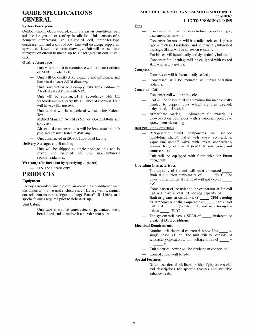
19
GUIDE SPECIFICATIONSGENERALSystem DescriptionOutdoor−mounted, air−cooled, split−system air conditioner unitsuitable for ground or rooftop installation. Unit consists of ahermetic compressor, an air−cooled coil, propeller−typecondenser fan, and a control box. Unit will discharge supply airupward as shown on contract drawings. Unit will be used in arefrigeration circuit to match up to a packaged fan coil or coilunit.Quality Assurance
— Unit will be rated in accordance with the latest editionof AHRI Standard 210.
— Unit will be certified for capacity and efficiency, andlisted in the latest AHRI directory.
— Unit construction will comply with latest edition ofANSI/ ASHRAE and with NEC.
— Unit will be constructed in accordance with ULstandards and will carry the UL label of approval. Unitwill have c−UL approval.
— Unit cabinet will be capable of withstanding FederalTestMethod Standard No. 141 (Method 6061) 500−hr saltspray test.
— Air−cooled condenser coils will be leak tested at 150psig and pressure tested at 450 psig.
— Unit constructed in ISO9001 approved facility.Delivery, Storage, and Handling
— Unit will be shipped as single package only and isstored and handled per unit manufacturer’srecommendations.
Warranty (for inclusion by specifying engineer)— U.S. and Canada only.
PRODUCTSEquipmentFactory assembled, single piece, air−cooled air conditioner unit.Contained within the unit enclosure is all factory wiring, piping,controls, compressor, refrigerant charge Puron� (R−410A), andspecial features required prior to field start−up.
Unit Cabinet— Unit cabinet will be constructed of galvanized steel,
bonderized, and coated with a powder coat paint.
AIR−COOLED, SPLIT−SYSTEM AIR CONDITIONER 24ABB3C
1−1/2 TO 5 NOMINAL TONSFans
— Condenser fan will be direct−drive propeller type,discharging air upward.
— Condenser fan motors will be totally enclosed, 1−phasetype with class B insulation and permanently lubricatedbearings. Shafts will be corrosion resistant.
— Fan blades will be statically and dynamically balanced.— Condenser fan openings will be equipped with coated
steel wire safety guards.
Compressor— Compressor will be hermetically sealed.
— Compressor will be mounted on rubber vibrationisolators.
Condenser Coil— Condenser coil will be air cooled.
— Coil will be constructed of aluminum fins mechanicallybonded to copper tubes which are then cleaned,dehydrated, and sealed.
— ArmorPlate coating − Aluminum fin material ispre−coated on both sides with a corrosion protectiveepoxy phenolic coating.
Refrigeration Components
— Refrigeration circuit components will includeliquid−line shutoff valve with sweat connections,vapor−line shutoff valve with sweat connections,system charge of Puron� (R−410A) refrigerant, andcompressor oil.
— Unit will be equipped with filter drier for Puronrefrigerant.
Operating Characteristics— The capacity of the unit will meet or exceed _____
Btuh at a suction temperature of _____ �F/�C. Thepower consumption at full load will not exceed _____kW.
— Combination of the unit and the evaporator or fan coilunit will have a total net cooling capacity of _____Btuh or greater at conditions of _____ CFM enteringair temperature at the evaporator at _____ �F/�C wetbulb and _____ �F/�C dry bulb, and air entering theunit at _____ �F/�C.
— The system will have a SEER of _____ Btuh/watt orgreater at DOE conditions.
Electrical Requirements— Nominal unit electrical characteristics will be _____ v,
single phase, 60 hz. The unit will be capable ofsatisfactory operation within voltage limits of _____ vto _____ v.
— Unit electrical power will be single point connection.
— Control circuit will be 24v.Special Features
— Refer to section of this literature identifying accessoriesand descriptions for specific features and availableenhancements.

20
Copyright 2015 Carrier Corp. � 7310 W. Morris St. � Indianapolis, IN 46231
Manufacturer reserves the right to change, at any time, specifications and designs without notice and without obligations.
Catalog No: 24ABB3C-8PD
Replaces: 24ABB3C-7PD
Edition Date: 08/15