PRODUCT DATA - Nilan 77.6 W Sound power level L WA) 56 dB(A) Reference flow rate 0.060 m3/s (215.6...
20
COMFORT 200 TOP BY NILAN PRODUCT DATA Domestic Ventilation < 308 m 3 /h Passive heat recovery Ventilation & passive heat recovery
Transcript of PRODUCT DATA - Nilan 77.6 W Sound power level L WA) 56 dB(A) Reference flow rate 0.060 m3/s (215.6...
COMFORT 200 TOP BY NILAN
PRODUCT DATA
Domestic Ventilation < 308 m3/h
Passive heat recovery
Ventilation & passive heat recovery
2
COMFORT 200 TOP Product description
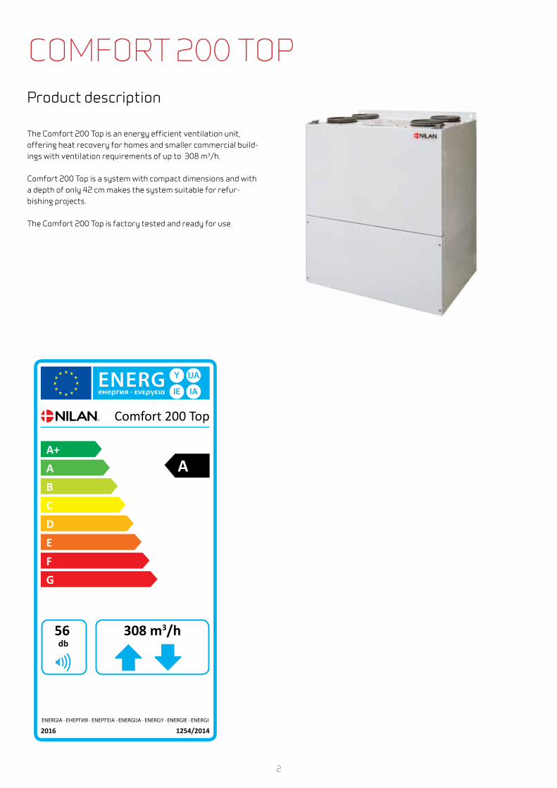
The Comfort 200 Top is an energy efficient ventilation unit, offering heat recovery for homes and smaller commercial build-ings with ventilation requirements of up to 308 m3/h.
Comfort 200 Top is a system with compact dimensions and with a depth of only 42 cm makes the system suitable for refur-bishing projects.
The Comfort 200 Top is factory tested and ready for use.
Comfort 200 Top
A+ A B C D E F G
A
2016 1254/2014ENERGIA · ЕНЕРГИЯ · ΕΝΕΡΓΕΙΑ · ENERG ENERGI
db308 m3/h56
3
COMFORT 200 TOP BY NILAN
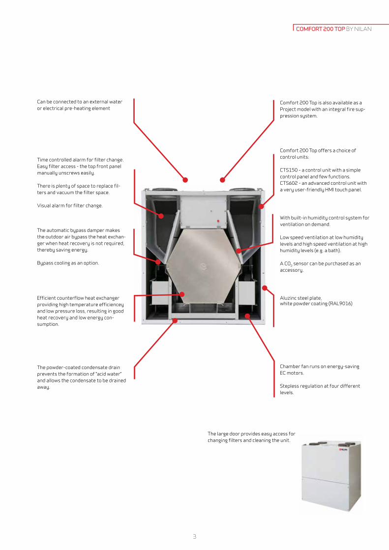
Time controlled alarm for filter change. Easy filter access - the top front panel manually unscrews easily.
There is plenty of space to replace fil-ters and vacuum the filter space.
Visual alarm for filter change.
Can be connected to an external water or electrical pre-heating element
The automatic bypass damper makes the outdoor air bypass the heat exchan-ger when heat recovery is not required, thereby saving energy.
Bypass cooling as an option.
Efficient counterflow heat exchanger providing high temperature efficiencey and low pressure loss, resulting in good heat recovery and low energy con-sumption.
The powder-coated condensate drain prevents the formation of “acid water” and allows the condensate to be drained away.
Chamber fan runs on energy-saving EC motors.
Stepless regulation at four different levels.
Comfort 200 Top offers a choice of control units:
CTS150 – a control unit with a simple control panel and few functions.CTS602 – an advanced control unit with a very user-friendly HMI touch panel.
Comfort 200 Top is also available as a Project model with an integral fire sup-pression system.
Aluzinc steel plate, white powder coating (RAL9016)
The large door provides easy access for changing filters and cleaning the unit.
With built-in humidity control system for ventilation on demand.
Low speed ventilation at low humidity levels and high speed ventilation at high humidity levels (e.g. a bath).
A CO2 sensor can be purchased as an accessory.
4
TECHNICAL DATA
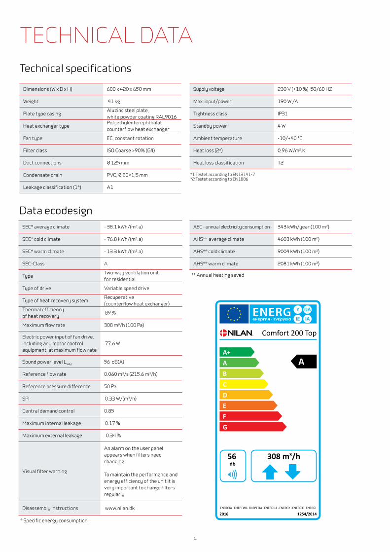
Dimensions (W x D x H) 600 x 420 x 650 mm
Weight 41 kg
Plate type casingAluzinc steel plate, white powder coating RAL9016
Heat exchanger type Polyethylenterephthalat counterflow heat exchanger
Fan type EC, constant rotation
Filter class ISO Coarse >90% (G4)
Duct connections Ø 125 mm
Condensate drain PVC, Ø 20×1,5 mm
Leakage classification (1*) A1
SEC* average climate - 38.1 kWh/(m2.a)
SEC* cold climate - 76.8 kWh/(m2.a)
SEC* warm climate - 13.3 kWh/(m2.a)
SEC-Class A
TypeTwo-way ventilation unit for residential
Type of drive Variable speed drive
Type of heat recovery systemRecuperative (counterflow heat exchanger)
Thermal efficiency of heat recovery
89 %
Maximum flow rate 308 m3/h (100 Pa)
Electric power input of fan drive, including any motor control equipment, at maximum flow rate
77.6 W
Sound power level LWA) 56 dB(A)
Reference flow rate 0.060 m3/s (215.6 m3/h)
Reference pressure difference 50 Pa
SPI 0.33 W/(m3/h)
Central demand control 0.85
Maximum internal leakage 0.17 %
Maximum external leakage 0.34 %
Visual filter warning
An alarm on the user panel appears when filters need changing.
To maintain the performance and energy efficiency of the unit it is very important to change filters regularly.
Disassembly instructions www.nilan.dk
* Specific energy consumption
Supply voltage 230 V (±10 %), 50/60 HZ
Max. input/power 190 W /A
Tightness class IP31
Standby power 4 W
Ambient temperature -10/+40 °C
Heat loss (2*) 0,96 W/m2.K
Heat loss classification T2
*1 Testet according to EN13141-7 *2 Testet according to EN1886
AEC - annual electricity consumption 343 kWh/year (100 m2)
AHS** average climate 4603 kWh (100 m2)
AHS** cold climate 9004 kWh (100 m2)
AHS** warm climate 2081 kWh (100 m2)
** Annual heating saved
Technical specifications
Data ecodesign
Comfort 200 Top
A+ A B C D E F G
A
2016 1254/2014ENERGIA · ЕНЕРГИЯ · ΕΝΕΡΓΕΙΑ · ENERG ENERGI
db308 m3/h56

5
COMFORT 200 TOP BY NILAN
Dimensional drawingAll dimensions are in mm.
Connections
1: Fresh air 2: Supply air 3: Extract air 4: Discharge air 5: Condensate drain 6: Electric and water heating
6
650
600
550 35
195
12
5420
146
105 390 105
106
195
122
Ø 125
1
2
3
4
6105 390 105
106
195
122
Ø 125
1
2
3
4
6
650
600
550 35
195
12
5420
146
105 390 105
106
195
122
Ø 125
1
2
3
4
6105 390 105
106
195
122
Ø 125
1
2
3
4
6
650
600
550 35
195
12
5420
146
105 390 105
106
195
122
Ø 125
1
2
3
4
6105 390 105
106
195
122
Ø 125
1
2
3
4
6
650
600
550 35
195
12
5420
146
105 390 105
106
195
122
Ø 125
1
2
3
4
6105 390 105
106
195
122
Ø 125
1
2
3
4
Right modelLeft model

6
PLANNING DATACapacityCapacity of standard unit as a function of qv and Pt, ext.
SEL values according to EN 13141-7 are for standard units with ISO Coarse >90% (G4) filters and without heating element.
SEL values represent the unit´s total power comsumption for both ventilator, excl. control.
Testet according to EN13141-7
Attention! The SEL values are measured and stated as a total value for both fans.
Temperature efficiencyTemperature efficiency for units with counterflow heat exchanger according to EN13141-7 (dry).
50 75 100 125 150 175 200 225 250 275 300 3250
25
50
75
100
125
150
175
200
225
250
20 30 40 50 60 70 80 90
qv (m3/h)
qv (l/s)
Pa
Max Pa
1.000 J/m3
800 J/m3
50 75 100 125 150 175 200 225 250 275 300 32585
86
87
88
89
90
91
92
93
94
ηt (%)
qv [m3/h]
qv [l/s]20 30 40 50 60 70 80 90
7
COMFORT 200 TOP BY NILAN
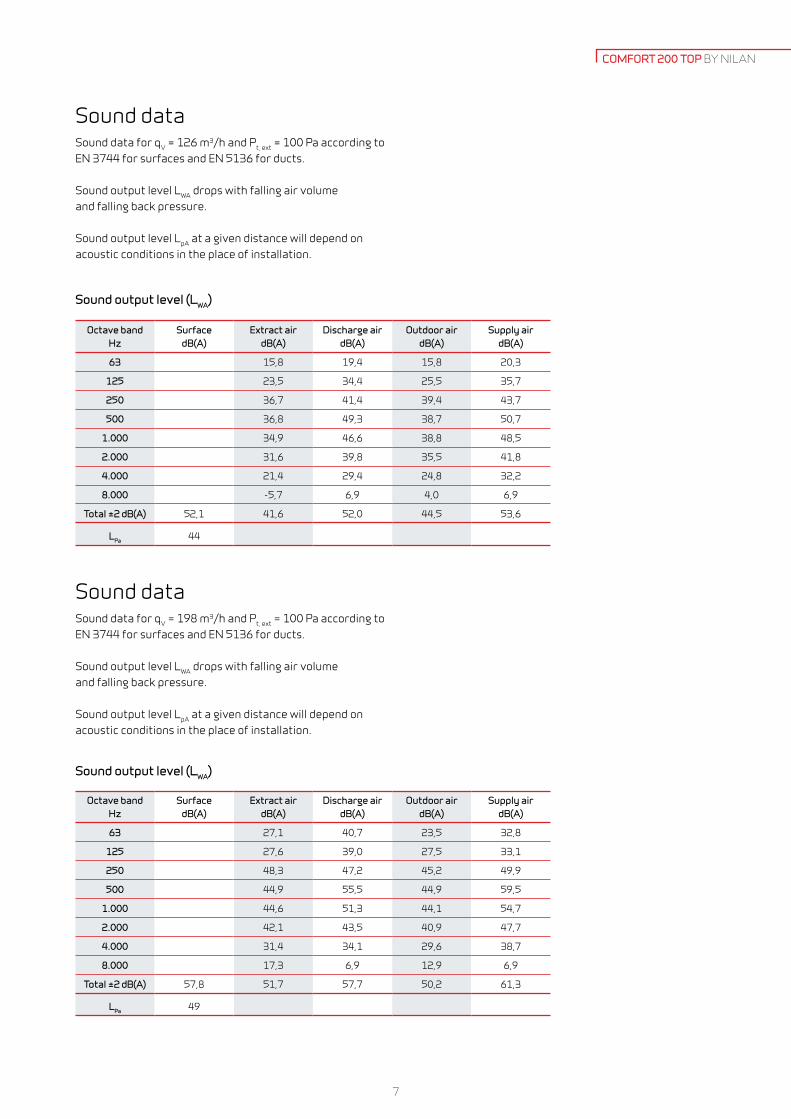
Sound output level (LWA)
Sound dataSound data for qV = 126 m3/h and Pt, ext = 100 Pa according to EN 3744 for surfaces and EN 5136 for ducts.
Sound output level LWA drops with falling air volume and falling back pressure.
Sound output level LpA at a given distance will depend on acoustic conditions in the place of installation.
Octave band Hz
Surface dB(A)
Extract air dB(A)
Discharge air dB(A)
Outdoor air dB(A)
Supply air dB(A)
63 15,8 19,4 15,8 20,3
125 23,5 34,4 25,5 35,7
250 36,7 41,4 39,4 43,7
500 36,8 49,3 38,7 50,7
1.000 34,9 46,6 38,8 48,5
2.000 31,6 39,8 35,5 41,8
4.000 21,4 29,4 24,8 32,2
8.000 -5,7 6,9 4,0 6,9
Total ±2 dB(A) 52,1 41,6 52,0 44,5 53,6
LPa 44
Octave band Hz
Surface dB(A)
Extract air dB(A)
Discharge air dB(A)
Outdoor air dB(A)
Supply air dB(A)
63 27,1 40,7 23,5 32,8
125 27,6 39,0 27,5 33,1
250 48,3 47,2 45,2 49,9
500 44,9 55,5 44,9 59,5
1.000 44,6 51,3 44,1 54,7
2.000 42,1 43,5 40,9 47,7
4.000 31,4 34,1 29,6 38,7
8.000 17,3 6,9 12,9 6,9
Total ±2 dB(A) 57,8 51,7 57,7 50,2 61,3
LPa 49
Sound dataSound data for qV = 198 m3/h and Pt, ext = 100 Pa according to EN 3744 for surfaces and EN 5136 for ducts.
Sound output level LWA drops with falling air volume and falling back pressure.
Sound output level LpA at a given distance will depend on acoustic conditions in the place of installation.
Sound output level (LWA)
8
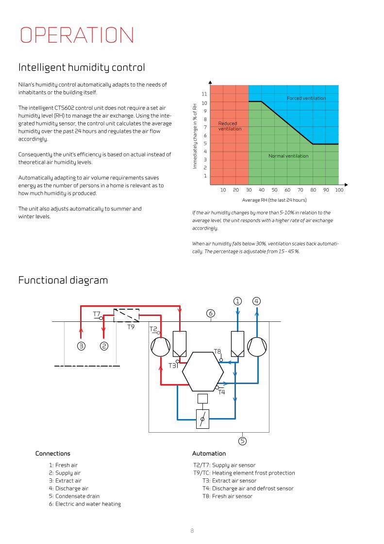
Functional diagram
OPERATIONIntelligent humidity controlNilan’s humidity control automatically adapts to the needs of inhabitants or the building itself.
The intelligent CTS602 control unit does not require a set air humidity level (RH) to manage the air exchange. Using the inte-grated humidity sensor, the control unit calculates the average humidity over the past 24 hours and regulates the air flow accordingly.
Consequently the unit’s efficiency is based on actual instead of theoretical air humidity levels.
Automatically adapting to air volume requirements saves energy as the number of persons in a home is relevant as to how much humidity is produced.
The unit also adjusts automatically to summer and winter levels.
5
6
7
8
9
4
3
2
1
10
11
40 50 60 70 80 90 100302010Im
med
iate
ly c
hang
e in
% o
f RH
Average RH (the last 24 hours)
Reducedventilation
Forced ventilation
Normal ventilation
If the air humidity changes by more than 5-10% in relation to the
average level, the unit responds with a higher rate of air exchange
accordingly.
When air humidity falls below 30%, ventilation scales back automati-
cally. The percentage is adjustable from 15 - 45 %.
1
T4
T3
T8
T2
2
5
4
6
3
T7
T9
Connections
1: Fresh air 2: Supply air 3: Extract air 4: Discharge air 5: Condensate drain 6: Electric and water heating
Automation
T2/T7: Supply air sensor T9/TC: Heating element frost protection T3: Extract air sensor T4: Discharge air and defrost sensor T8: Fresh air sensor

9
Water side Air side
Temperature input/output
[°C]
Flow
[m3/h]
Pressure drop
[kPa]
Output
[kW]
Flow
[m3/h]
Temperature before WHE*
[°C]
Temperature after WHE*
[°C]
Pressure drop over WHE*
[Pa]
40/30
0.04 0.85 0.52 100 16 31.1 2
0.06 1.25 0.64 135 16 29.8 3
0.08 2.18 0.87 210 16 28.1 6
60/40
0.04 0.69 0.94 100 16 43.5 2
0.05 1.00 1.16 135 16 41.1 3
0.07 1.75 1.58 210 16 38.0 6
70/40
0.03 0.40 1.06 100 16 47.0 2
0.04 0.58 1.30 135 16 44.2 3
0.05 1.00 1.76 210 16 40.5 6
Capacity water heating element
* Water heating element.
Capacity - Heating element (accessory CTS602)
Electrical heating elementThe electrical heating element is fitted in the supply air duct at a distance of min. 2 x duct diameter from the system´s fresh air inlet connection pipe (normally min 320 mm.) and connected to the CTS602 control panel and 230 V supply.
The electrical heating surface can supply up to 1,2 kW of heat.
Water heating element for duct fittingThe water heating element is designed to be built into duct and must be connected to the primary heating supply and the CTS602 control. The water heating element includes copper pipes and aluminium fins.
Capacities can be seen in the table below.
COMFORT 200 TOP BY NILAN

10
CTS150 Control The CTS150 control unit is a simple control unit used to control the 200 Top system. It offers the user only limited access to set-tings.
Users can adjust the air volume and humidity levels.
The control unit also shows whether the system is working and when an alarm is triggered.
To set and regulate the system, it has to be connected to a PC via a USB flash drive. Download the software from NilanNet and install. The software can be used not only to set the system, but also to read operating data.
AUTOMATION CTS150
Functional overview + Standard
- Accessories
Filter monitor Filter monitor with timer (factory default setting is 90 days). Adjustable to 30/90/180/360 days. +
Bypass Bypassing the outdoor air reduces heat recovery when heat recovery are not required. +
Humidity control Allows you to set a higher or lower ventilation step in the case of high/low air humidity. +
Summer/Winter operation Possible to set operation for summer and winter. +
Winter low Allows you to select a low ventilation step in the case of low outside temperatures. +
Defrost function Temperature-based automatic function for defrosting the heat exchanger. +
Temperature control The system’s overriding temperature sensor is T3 extract air. +
Air volume Allows you to set four ventilation steps stepless. Supply air and extract air are set individually.Step 1 < 25% - Step 2 < 45% - Step 3 < 70% - Step 4 < 100%
+
User option It is also possible to activate user selection mode (Step 4) via a potential-free contact. -
Software screen shot of the CTS150 automatic control and good overview on system settings.

11
Electrical pre-heating element (Frost protection)To prevent the highly efficient counterflow heat exchanger from freezing, we recommend that you fit an electrical pre-heating element. The element consumes very little energy but improves heat recovery. The net result is more cost-efficient operation. See page 16.
User selection/Range hood solutionIt is also possible to activate user selection mode (Step 4) via a potential-free contact. The set includes a cable with two RJ12 connectors. Connect the connector at the unit and connect the control panel and the 10 m of cable, for example, to a range hood, ind the two-connectionbox.
User selection/range hood-damper solution It is also possible to activate user selection mode (Step 4) via a potential-free contact. The set includes an RJ12 cable, a connection box for the range hood, damper connections as well as a 230V main supply plug.
EM-boxThe EM-box distributes extract air between kitchen and bathroom. If the range hood runs via the ventilation system and is operating, extract air flow from the bathroom is reduced to ensure that there is enough air to allow the cooker hood to extract cooking odours. To protect the system, the EM-box is fitted with a metal filter, which efficiently eliminates fat particles from range hood air.
Pollenfilter ISO ePM1 65-80% (F7)Comfort 200 Top are as standard delivered with ISO Coarse >90% (G4) filter. If there are someone in the housing which suffers of pollen allergy, it is possible to order a ISO ePM1 65-80% (F7) pollenfilter to minimize the amount af Pollen in the supply-air.
Water trapTo prevent ”false” air being sucked into the system via the condensate drain, the system must be fitted with a water trap. While there is water in the condensate drain, the water trap works well. However, during the summer months when there is no condensation of extract air, the water trap will dry out (and therefore cease to prevent ”false” air intake). A Nilan water trap with ball prevents ”false” air flow all year round.
Flexible silencingFor easy fitting and excellent noise reduction between the system and the distribu-tion box and/or between the system and roof vents.
ACCESSORIES CTS150 COMFORT 200 TOP BY NILAN

12
External communication
The CTS602 control unit communicates by default with Modbus RTU RS485 communication. A CTS system using this form of communication can easily be connected to the unit.
Nilan units have an open Modbus communication, i.e. not only can the unit be monitored, but its operation can also be set in the same way as it can via the operating panel.
The protocol is by default set up for a Modbus RTU30 address; however, values can be set between 1 and 247.
A Modbus converter allows you to connect one or more units to a computer to monitor and control the unit.
CTS602 Control
The CTS 602 HMI touch panel is featuring a wide range of functions, e.g., menu-controlled operation, weekly program-me settings, filter monitor with timer, fan speed adjustment, summer bypass (free cooling), supply-heating element con-trol, error messages etc.
The CTS 602 comes with factory settings, including a defaultsetting which can be customised to operational requirementsto achieve optimum operation and utilisation of the system.
There is an option for selecting between 2 front page images for the main screen.
Operating instructions for the CTS 602 can be found in a sepa-rate user manual supplied with the unit.
AUTOMATION CTS602

13
COMFORT 200 TOP BY NILAN
Functional overview + Standard- Accessories
3 levels The control function is divided into 3 levels: User/Service/Factory with various options at each level +
Weekly plan The unit has 3 weekly programmes (with a factory setting of “off”)• Programme 1: for working families• Programme 2: for stay-at-home families• Programme 3: for businessesThere is also an option for you to set your own weekly programme.
+
User option 1 & 2 This allows you to override the operating mode in the main menu via an external potential-free contact or PIR sensor.
+
Alarms Alarm log featuring the last 16 alarms. +
Datalog Possible to log data. Capacity 46.000 logs• Adjustable between 1 and 120 minutes• If “OFF”, only events and alarms are logged
Filter monitor Filter monitor with timer (factory default setting is 90 days). Adjustable to 30/90/180/360 days. +
Bypass Bypassing the outdoor air reduces heat recovery when heat recovery are not required. +
Air quality Allows you to choose whether to switch humidity sensors and/or CO2 sensors on and off. +/-
Humidity control Allows you to set a higher or lower ventilation step in the case of high/low air humidity. +
CO2 control Allows you to set a higher or lower ventilation step in the case of a high CO2 level. -
Summer/Winter operation Possible to set operation for summer and winter
Winter low Allows you to select a low ventilation step in the case of low outside temperatures +
Defrost function Temperature-based automatic function for defrosting the heat exchanger. +
Frostprotection Should a heating system fail, the unit is turned off automatically to reduce the risk of damage to the water heating coil from frost due to further cooling by the system.
+
Temperature control Allows you to select the temperature sensor which will control the unit.• T3 EXHAUST (extract air)
+
Room low Stops the unit when the room temperature reaches a pre-determined low, avoiding further cooling in case of a malfunction in the central heating system. The low temperature can be set from 1 - 20 degrees, controlled by:• T3 EXHAUST (extract air)
+
Air volume Allows you to set four ventilation steps stepless. Supply air and extract air are set individually.Step 1 < 25% - Step 2 < 45% - Step 3 < 70% - Step 4 < 100%
+
External fire alarm Possible to connect the unit to external firealarm. +
Joint alarm The unit can be connected to an external fire alarm. +
Constant pressure control Allows control from both the extract air and supply air side. -
Cooling Via bypass (can only cool with outdoor temperature) andcool recovery (can only cool with indoor temperature).This allows you to choose whether to run the system at a higher or the highest ventilation step during cooling.The weekly programme has an option for setting cooling at night.
+
Intake air control Allows you to set the regulator to control the intake air temperature/supply air(only available if the control unit has been configured for a supply-heating element).
+
External water heating element
• Temperature sensor T7 is an supply air sensor• Integrated frost protection for external water heating element• Motorised valve and circulation pump control unit
-
External electric heating element
• Temperature sensor T7 is an supply air sensor• Overheating protection
-
Delayed start-up There is a possibility for a delayed start-up by the fans, when a closing damper is installed. +
Reset Allows you to restore the factory settings. +
Manual test Allows you to test the unit’s functions manually. +
Language Option for setting the relevant language (Danish/Finnish/Norwegian/Swedish/German/English/French/Polish).
+
14
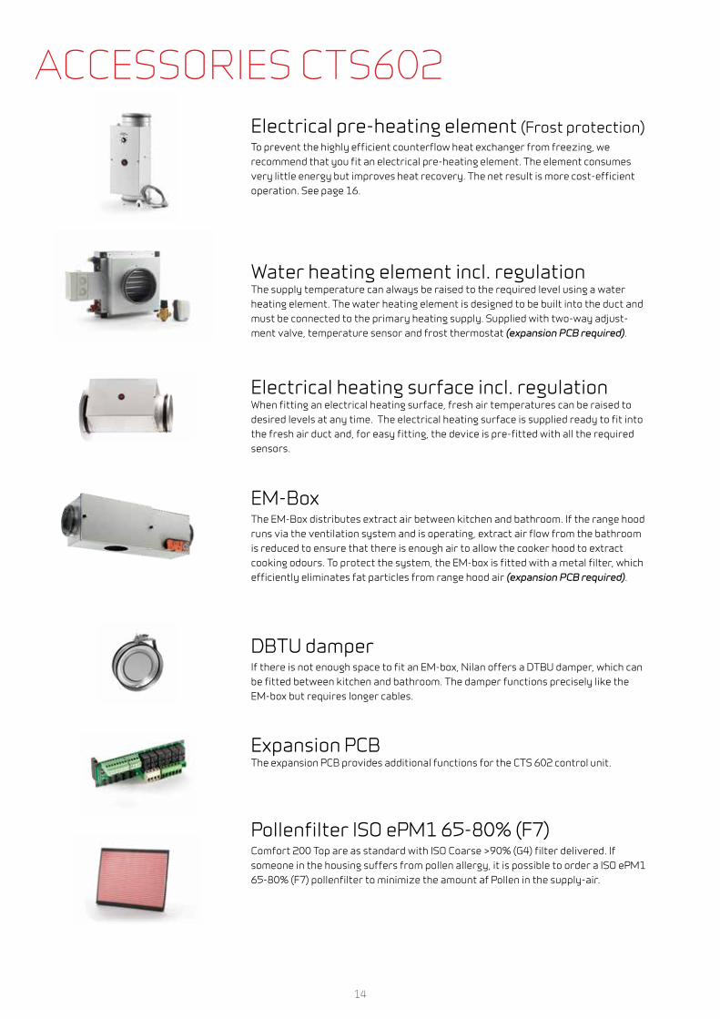
Electrical pre-heating element (Frost protection)To prevent the highly efficient counterflow heat exchanger from freezing, we recommend that you fit an electrical pre-heating element. The element consumes very little energy but improves heat recovery. The net result is more cost-efficient operation. See page 16.
Water heating element incl. regulation The supply temperature can always be raised to the required level using a water heating element. The water heating element is designed to be built into the duct and must be connected to the primary heating supply. Supplied with two-way adjust-ment valve, temperature sensor and frost thermostat (expansion PCB required).
Electrical heating surface incl. regulation When fitting an electrical heating surface, fresh air temperatures can be raised to desired levels at any time. The electrical heating surface is supplied ready to fit into the fresh air duct and, for easy fitting, the device is pre-fitted with all the required sensors.
EM-BoxThe EM-Box distributes extract air between kitchen and bathroom. If the range hood runs via the ventilation system and is operating, extract air flow from the bathroom is reduced to ensure that there is enough air to allow the cooker hood to extract cooking odours. To protect the system, the EM-box is fitted with a metal filter, which efficiently eliminates fat particles from range hood air (expansion PCB required).
DBTU damperIf there is not enough space to fit an EM-box, Nilan offers a DTBU damper, which can be fitted between kitchen and bathroom. The damper functions precisely like the EM-box but requires longer cables.
Expansion PCB The expansion PCB provides additional functions for the CTS 602 control unit.
Pollenfilter ISO ePM1 65-80% (F7)Comfort 200 Top are as standard with ISO Coarse >90% (G4) filter delivered. If someone in the housing suffers from pollen allergy, it is possible to order a ISO ePM1 65-80% (F7) pollenfilter to minimize the amount af Pollen in the supply-air.
ACCESSORIES CTS602
15
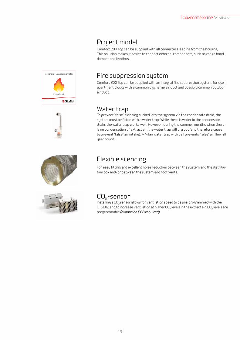
Project modelComfort 200 Top can be supplied with all connectors leading from the housing. This solution makes it easier to connect external components, such as range hood, damper and Modbus.
Fire suppression systemComfort 200 Top can be supplied with an integral fire suppression system, for use in apartment blocks with a common discharge air duct and possibly common outdoor air duct.
Water trapTo prevent ”false” air being sucked into the system via the condensate drain, the system must be fitted with a water trap. While there is water in the condensate drain, the water trap works well. However, during the summer months when there is no condensation of extract air, the water trap will dry out (and therefore cease to prevent ”false” air intake). A Nilan water trap with ball prevents ”false” air flow all year round.
Flexible silencingFor easy fitting and excellent noise reduction between the system and the distribu-tion box and/or between the system and roof vents.
CO2-sensor Installing a CO2 sensor allows for ventilation speed to be pre-programmed with the CTS602 and to increase ventilation at higher CO2 levels in the extract air. CO2 levels are programmable (expansion PCB required).
Integreret Brandautomatik
Installeret
COMFORT 200 TOP BY NILAN

16
OPERATION
tAußen > -3°C
tAußen < -3°C
The energy used for the preheating is not wasted, as it ensures a constant high temperature efficiency
Frost protectionAll ventilation units with a counterflow heat exchanger will ice up if the outdoor temperature is below freezing for a prolonged period.
The extracted air condenses when it is cooled down during heat recovery. The high temperature efficiency will slowly turn the condensate to ice, which will block up the counterflow heat exchanger unless remedial action is taken.
It should be considered whether the unit’s operation can be protected during a lengthy period of frost or whether it is acceptable to decrease its operation.
In homes which are occupied at night, it would be advisable to protect the unit against frost when the outdoor tempera-ture is coldest by using a pre-heating element. On the other hand, if the ventilation is for an office, it may be acceptable to decrease the operating level at night.
ɳt[%]
Tem
pera
ture
eff
icie
ncy
Operation Ice building Ice buildingDefrost Defrost
With pre-heater
Defrost function
Outdoor temperature< -3 °CNormal operation
Pre-heaterinstalled
Normal operation secureduntil outdoor temp. < -12 °C
When outdoor temp. < -12 °C reduced air volume
Defrost function starts when:
Outdoor temp < 1 °C (T8)Discharge air < 3 °C in 5 min.
Defrosting stops when:Discharge air > 7°C (T4)
No After 30 min.
No
Yes
Yes
1. Bypass damper opens 2. The intake motor switches off3. Warm extracted air will flow through the heat exchanger4. The ice is melting
Frost protection
Air volume 126 m3/h 216 m3/h
Frost protection when outside temperature is -2 °C -2 °C
Hours during the year 676 676
Energy used to frost protection via pre-heating 107 kWh/a 183 kWh/a
Loss of energy when icing 105 kWh/a 180 kWh/a
Loss of energy when deicing 200 kWh/a 343 kWh/a
Energy savings by using frost protection 198 kWh/a 340 kWh/a
Average calculation by Danish dry weather data.
The example below shows the energy used to frost protect versus defrosting.

17
Min. 20 cm
Min. 50 cm
Min. 60 cm
DELIVERY AND HANDLINGTransport and storageComfort 200 Top is shipped in protective packaging for transport and storage. Comfort 200 Top must be stored in a dry place in its original packaging until installation.
The packaging should only be removed immediately prior to installation.
Installation conditionsDuring installation, future service and maintenance should be taken into account. We recommend a minimum gap in front of the unit of 60 cm.
The unit must be installed level for the sake of the condensate drain. The condensate drain requires clearance of min. 12,5 cm under the drain nozzle.
Electric heating elements (accessories) are fitted in the duct. The heating element must be insulated using fire-resistant insulation material.
The electric heating element must be connected by an authorised electrician.
Installation of electric heating element
Electric heating
element
Electric pre-heating
element with
temperature sensor
Min. 32 cm
Min. 32 cm
COMFORT 200 TOP BY NILAN

18
NILAIR
Enabling the impossible
Traditional air distribution systems take up a lot of space and often make special building structures impossible. NilAIR virtual-ly eliminates this problem, due to the tubes’ size and flexibility.
Advantages
• Flexible and space-saving solution• Rapid and simple installation with a click system• Dimensionally stable and corrosion-resistant quality material• Simple regulation of the air supply volume• Low weight• Airtight• Easy to clean• Easy to handle and transport• Prevents sound travelling from room to room
NilAIR is already installed in thousands of European homes and since its introduction more than ten years ago its use has stea-dily increased, due to the rapid and easy installation without any special tools being required.
NilAIR is installed together with a ventilation unit,which in simple terms consists of distribution boxes from which tubes are led out to air extraction and air supply boxes in the individual rooms.
NilAIR can be installed in ceilings, walls or floors. The lightweight tubes can be used for even the most complicated tube align-ments, where e.g. traditional spiral ducts cannot be used.
Installation examples

19
NILAIR PRINCIPLE NILAIR BY NILAN
Distribution manifold supply air(mounted in floor or ceiling)
Air supply(mounted in floor, wall or ceiling)
Air extraction(mounted in wall or ceiling)
Living room
Utility room
Bathroom
Bathroom
Kitchen
Room
Room
Family room
Bedroom
Distribution manifold extract air(mounted in floor or ceiling)
Ventilation unit
Soundflex

Ver.
1.10
- 20
18.1
1WWW.NILAN.DK
Nila
n A
/S a
ssum
es n
o re
spon
sibi
lity
for
any
erro
rs o
r om
issi
ons
in th
e pr
inte
d in
form
atio
n m
ater
ial o
r fo
r lo
ss o
r da
mag
e th
at m
ay fo
llow
from
the
use
of s
uch
publ
ishe
d m
ater
ials
- w
heth
er s
uch
loss
of d
amag
e is
cau
sed
by e
rror
s or
in
expe
dien
cies
in th
e m
ater
ial o
r ot
herw
ise.
Nila
n A
/S r
eser
ves
the
righ
t wit
hout
pri
or n
otic
e to
cha
nge
prod
ucts
and
info
rmat
ion
mat
eria
l. A
ll tr
adem
arks
are
the
prop
erty
of N
ilan
A/S
. All
righ
ts r
eser
ved.
INFORMATION FROM A TO ZNilan develops and manufactures premium-quality, energy-saving ventilation and heat pump solutionsthat provide a healthy indoor climate and low-level energy consumption with the greatest consideration forthe environment. In order to facilitate each step in the construction process – from choosing the solutionthrough to planning, installation and maintenance – we have created a series of information material whichis available for download at www.nilan.dk.
BrochureGeneral information about the solution and its benefits.
Product dataTechnical information to ensure correct choice of solution.
Installation instructionsDetailed guide for instal-lation and initial adjust-ment of the solution.
User manualDetailed guide for regulation of the solution to ensure optimum day-to-day operation.
DrawingsTender documents and 3D drawings are available to down-load for planning purposes.
Visit us at www.nilan.dk to find outmore about our company and solutions,download further information and findyour nearest dealer.
Nilan A/SNilanvej 28722 HedenstedDenmarkTel. +45 76 75 25 00Fax +45 76 75 25 [email protected]
1000
136
340
254
212
136
340
254 296
560
508
Ø 160 mm
MONTAGEVEJLEDNINGCTS602 LIGHT BY NILAN
Comfort 252 / 302 Top / Polar
Version 3.00 - 26.11.2018
BRUGERVEJLEDNINGCTS602 LIGHT BY NILAN
Comfort 252 / 302 Top / Polar
Version 3.00 - 03.10.2018


![Nilan VPM 600-3200 Nilan VPM 600-3200 Active heat recovery and cooling ... nilan’s VPM series is an all-in-one solution, ... h`Z b a^c\Zg [dg YZi ad`Vadbg YZ! ] ...](https://static.fdocuments.us/doc/165x107/5b0c61817f8b9a02508c1701/nilan-vpm-600-vpm-600-3200-active-heat-recovery-and-cooling-nilans-vpm-series.jpg)