Product catalogue | 2012 SafeLink 2 Compact ring main · PDF file ·...
28
SafeLink 2 Compact ring main solution for secondary 12 kV distribution networks Product catalogue | 2012
Transcript of Product catalogue | 2012 SafeLink 2 Compact ring main · PDF file ·...
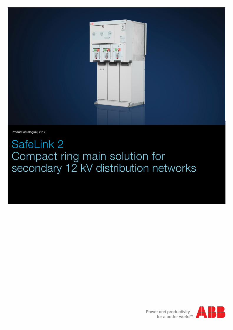
SafeLink 2Compact ring main solution for secondary 12 kV distribution networks
Product catalogue | 2012


3 Product Catalogue | Contents
Contents
Introduction 4
Overview 5
Product configurations 6
Range 8
Module technical data 9
Common technical data 11
Fuse selection tables 12
Automation 13
Optional features 14
Dimensions – 2-way / 3-way 20
Dimensions – 4-way / CFCF 21
Standards 22
Maintenance 23
Environmental declaration 24
4 Product Catalogue |
Introduction
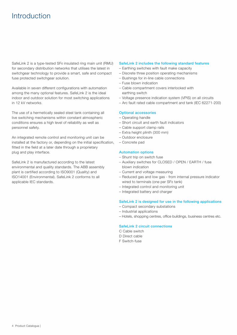
SafeLink 2 is a type-tested SF6 insulated ring main unit (RMU) for secondary distribution networks that utilises the latest in switchgear technology to provide a smart, safe and compact fuse protected switchgear solution.
Available in seven different configurations with automation among the many optional features. SafeLink 2 is the ideal indoor and outdoor solution for most switching applications in 12 kV networks.
The use of a hermetically sealed steel tank containing all live switching mechanisms within constant atmospheric conditions ensures a high level of reliability as well as personnel safety.
An integrated remote control and monitoring unit can beinstalled at the factory or, depending on the initial specification, fitted in the field at a later date through a proprietary plug and play interface.
SafeLink 2 is manufactured according to the latest environmental and quality standards. The ABB assembly plant is certified according to ISO9001 (Quality) and ISO14001 (Environmental). SafeLink 2 conforms to all applicable IEC standards.
SafeLink 2 includes the following standard features– Earthing switches with fault make capacity– Discrete three position operating mechanisms– Bushings for in-line cable connections– Fuse blown indication– Cable compartment covers interlocked with
earthing switch– Voltage presence indication system (VPIS) on all circuits– Arc fault rated cable compartment and tank (IEC 62271-200)
Optional accessories– Operating handle– Short circuit and earth fault indicators – Cable support clamp rails– Extra height plinth (300 mm)– Outdoor enclosure– Concrete pad
Automation options– Shunt trip on switch fuse– Auxiliary switches for CLOSED / OPEN / EARTH / fuse
blown indication– Current and voltage measuring– Reduced gas and low gas - from internal pressure indicator
wired to terminals (one per SF6 tank)– Integrated control and monitoring unit – Integrated battery and charger
SafeLink 2 is designed for use in the following applications– Compact secondary substations– Industrial applications– Hotels, shopping centres, office buildings, business centres etc.
SafeLink 2 circuit connectionsC Cable switchD Direct cableF Switch-fuse

5 Product Catalogue | Overview
Overview
Each switch is in the form of a three-position switch giving CLOSED, OPEN and EARTH conditions with respect to the connected cable. The status of each switch is indicated by the symbol visible in the mimic panel and confirmed by the mimic diagram. Active flags in the diagram match the circuit condition with black confirming CLOSED switches and white indicating switches that are OPEN. Access to the cable box and fuse compartment is interlocked with the switch status.
SafeLink 2 units can be supplied with direct busbar connections (D) in place of load break switches to allow SafeLink 2 units to be joined with an external cable connection.
The operating handle is designed to give a delay between switching operations. Insertion of the operating handle is controlled by a rotary selector, which has one of three possible states:1. Handle access blocked.2. Switching between OPEN and CLOSED and switch-fuse
reset possible.3. Switching between OPEN and EARTH possible.
The selector handle can be padlocked in any of these three positions.
CoversUpper and lower front covers made from Aluzink® with a light grey (RAL 7035) powder coat finish. UV stabilised polycarbonate labels contain the mimic diagram of the main circuit with the position indicators for the switching devices.
Cable compartmentsEach switch module has a separate cable compartment that is divided from the others by means of partition walls. These partition walls can easily be removed, allowing unrestricted access for connection of cables.
The cable compartment covers are individually removable and contain additional inner panels (4 - 6 mm), for arc containment. These covers are manufactured from 2 mm Aluzink® (except the arc containment panel) and are powder coated with colour RAL 7035.
Upper front cover1. Fuses contained behind door2. Interlocked fuse access door catch3. Fuse blown indicator 4. Short circuit and earth fault indicators (optional)5. Gas gauge / gas gauge cover6. Rating plate / serial no.
Lower front cover7. Switch mode selector8. Separate mimic panels9. Voltage present indication system10. Interlocked cable compartment door
The SafeLink 2 unit is certified for use on distribution systems operating at up to 12 kV. SafeLink 2 is available in several configurations based on ring and fuse-protected switches: e.g. CFC, CCC, CFCC, and CFCF; where C denotes a load break switch and F a switch-fuse combination. The switch-fuse combination has three-phase tripping and when the switch is earthed, both sides of the fuses are connected to earth.
1 2 3 4
5
6
789
10
6 Product Catalogue | Product configurations
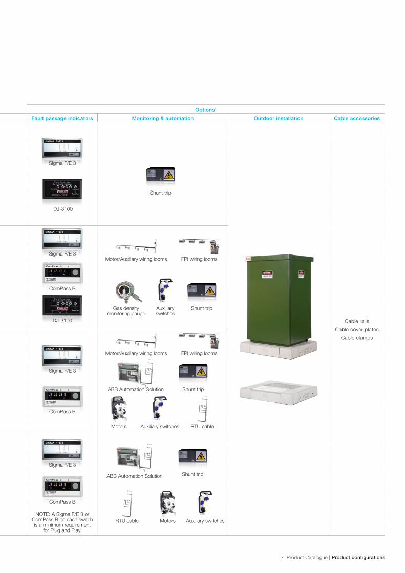
Included items Options1
Variants Connectivity Fault passage indicators Monitoring & automation Outdoor installation Cable accessories
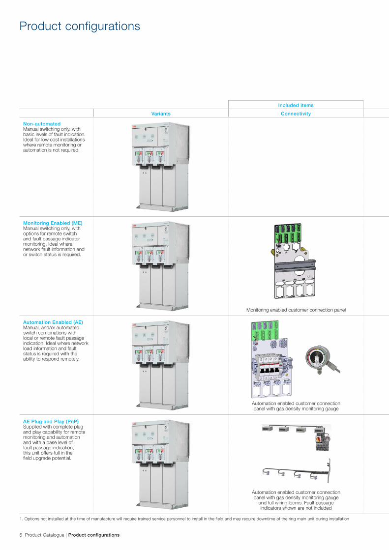
Non-automatedManual switching only, with basic levels of fault indication. Ideal for low cost installations where remote monitoring or automation is not required.
Cable railsCable cover plates
Cable clamps
Monitoring Enabled (ME)Manual switching only, with options for remote switch and fault passage indicator monitoring. Ideal where network fault information and or switch status is required.
Automation Enabled (AE)Manual, and/or automated switch combinations with local or remote fault passage indication. Ideal where network load information and fault status is required with the ability to respond remotely.
AE Plug and Play (PnP)Supplied with complete plug and play capability for remote monitoring and automation and with a base level of fault passage indication, this unit offers full in the field upgrade potential.
Automation enabled customer connection panel with gas density monitoring gauge
Monitoring enabled customer connection panel
1. Options not installed at the time of manufacture will require trained service personnel to install in the field and may require downtime of the ring main unit during installation
Product configurations
Automation enabled customer connection panel with gas density monitoring gauge
and full wiring looms. Fault passage indicators shown are not included
7 Product Catalogue | Product configurations
Included items Options1
Variants Connectivity Fault passage indicators Monitoring & automation Outdoor installation Cable accessories
Non-automatedManual switching only, with basic levels of fault indication. Ideal for low cost installations where remote monitoring or automation is not required.
Cable railsCable cover plates
Cable clamps
Monitoring Enabled (ME)Manual switching only, with options for remote switch and fault passage indicator monitoring. Ideal where network fault information and or switch status is required.
Automation Enabled (AE)Manual, and/or automated switch combinations with local or remote fault passage indication. Ideal where network load information and fault status is required with the ability to respond remotely.
AE Plug and Play (PnP)Supplied with complete plug and play capability for remote monitoring and automation and with a base level of fault passage indication, this unit offers full in the field upgrade potential.
Sigma F/E 3
ComPass B
NOTE: A Sigma F/E 3 or ComPass B on each switch is a minimum requirement
for Plug and Play.
Sigma F/E 3
Sigma F/E 3
Sigma F/E 3
DJ-3100
ComPass B
ComPass B
DJ-3100
Shunt trip
Shunt trip
Shunt trip
Shunt trip ABB Automation Solution
ABB Automation Solution
RTU cable Auxiliary switches
Auxiliary switches
Gas density monitoring gauge
RTU cableAuxiliary switchesMotors
Motors
FPI wiring looms
FPI wiring looms
Motor/Auxiliary wiring looms
Motor/Auxiliary wiring looms
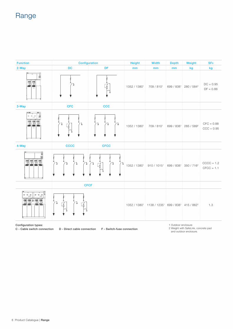
8 Product Catalogue | Range
Range
Configuration types: C - Cable switch connection D - Direct cable connection F - Switch-fuse connection
1 Outdoor enclosure2 Weight with SafeLink, concrete pad
and outdoor enclosure.
Function Configuration Height Width Depth Weight SF6
2-Way DC DF mm mm mm kg kg
1352 / 13801 709 / 8101 699 / 8381 280 / 5842DC = 0.95DF = 0.88
3-Way CFC CCC
1352 / 13801 709 / 8101 699 / 8381 285 / 5892CFC = 0.88CCC = 0.95
4-Way CCCC CFCC
1352 / 13801 910 / 10151 699 / 8381 350 / 7162CCCC = 1.2CFCC = 1.1
CFCF
1352 / 13801 1138 / 12351 699 / 8381 415 / 8622 1.3
9 Product Catalogue | Module technical data
Module technical data
Module C – Cable switch connection D – Direct cable connection F – Switch fuse connection
Technical data
Rated voltage kV 12 12 12Power frequency withstand voltage kV 28 / 32 28 28 / 32Impulse withstand voltage kV 95 / 110 95 95 / 110Rated normal current A 630 630 Fuse dependentBreaking capacities:- active load A 630 (E3) - 200 (E3)- closed loop A 630 (E3) - 200 (E3)- off load cable charging A 10 - 10Making capacity kA 52.5 peak / 21 rms - N/A (TDisc 21 kA)Short time current 1 sec. kA 21 21 N/A (Transfer current 1200 A)Short time current 3 sec. kA 21 rms 21 rms N/ANumber of mechanical operations n 1000 (M1) No switch 1000 (M1)Earthing switch
Rated voltage kV 12 - 12Power frequency withstand voltage kV 32 - 32Impulse withstand voltage kV 110 - 110Making capacity kA 52.5 peak / 21 rms - 7.9 peak / 3.2 rmsShort time current 1 sec. kA 21 - 21Short time current 3 sec. kA 21 rms - 7.9 peak / 3.2 rmsNumber of mechanical operations n 1000 (M0) - 1000 (M0)Standard features – Three position load
break switch with CLOSED/OPEN/EARTH positions
– Capacitive voltage indicator, VPIS to IEC 62271-206 with integrated indicator lamps (LED)
– Vertical cable bushings - from rear to front, L1 at the rear
– Earthing bar– Arc fault rated cable
compartment– Cable compartment front
covers interlocked with earth switch
– Capacitive voltage indicator, VPIS to IEC 62271-206 with integrated indicator lamps (LED)
– Vertical cable bushings - from rear to front, L1 at the rear
– Earthing bar– Arc fault rated cable
compartment– Cable compartment front
covers interlocked with earth switch
– Three position load break switch with CLOSED/OPEN/EARTH positions
– Capacitive voltage indicator, VPIS to IEC 62271-206 with integrated indicator lamps (LED)
– Vertical cable bushings - from rear to front, L1 at the rear
– Earthing bar– Arc fault rated cable
compartment– Cable compartment front
covers interlocked with earth switch
– Fuse access interlocked with earth switch
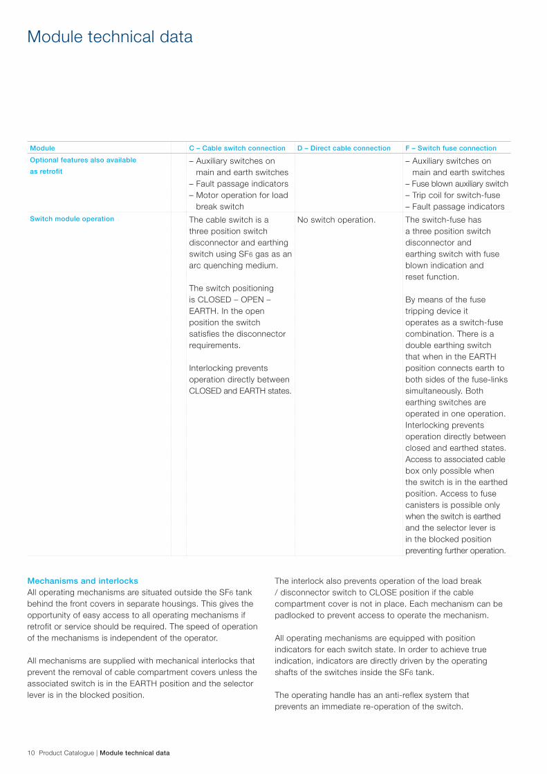
10 Product Catalogue | Module technical data
Module C – Cable switch connection D – Direct cable connection F – Switch fuse connectionOptional features also available as retrofit
– Auxiliary switches on main and earth switches
– Fault passage indicators– Motor operation for load
break switch
– Auxiliary switches on main and earth switches
– Fuse blown auxiliary switch– Trip coil for switch-fuse– Fault passage indicators
Switch module operation The cable switch is a three position switch disconnector and earthing switch using SF6 gas as an arc quenching medium.
The switch positioning is CLOSED – OPEN – EARTH. In the open position the switch satisfies the disconnector requirements.
Interlocking prevents operation directly between CLOSED and EARTH states.
No switch operation. The switch-fuse has a three position switch disconnector and earthing switch with fuse blown indication and reset function.
By means of the fuse tripping device it operates as a switch-fuse combination. There is a double earthing switch that when in the EARTH position connects earth to both sides of the fuse-links simultaneously. Both earthing switches are operated in one operation. Interlocking prevents operation directly between closed and earthed states. Access to associated cable box only possible when the switch is in the earthed position. Access to fuse canisters is possible only when the switch is earthed and the selector lever is in the blocked position preventing further operation.
Module technical data
Mechanisms and interlocksAll operating mechanisms are situated outside the SF6 tank behind the front covers in separate housings. This gives the opportunity of easy access to all operating mechanisms if retrofit or service should be required. The speed of operation of the mechanisms is independent of the operator.
All mechanisms are supplied with mechanical interlocks that prevent the removal of cable compartment covers unless the associated switch is in the EARTH position and the selector lever is in the blocked position.
The interlock also prevents operation of the load break / disconnector switch to CLOSE position if the cable compartment cover is not in place. Each mechanism can be padlocked to prevent access to operate the mechanism.
All operating mechanisms are equipped with position indicators for each switch state. In order to achieve true indication, indicators are directly driven by the operating shafts of the switches inside the SF6 tank.
The operating handle has an anti-reflex system that prevents an immediate re-operation of the switch.
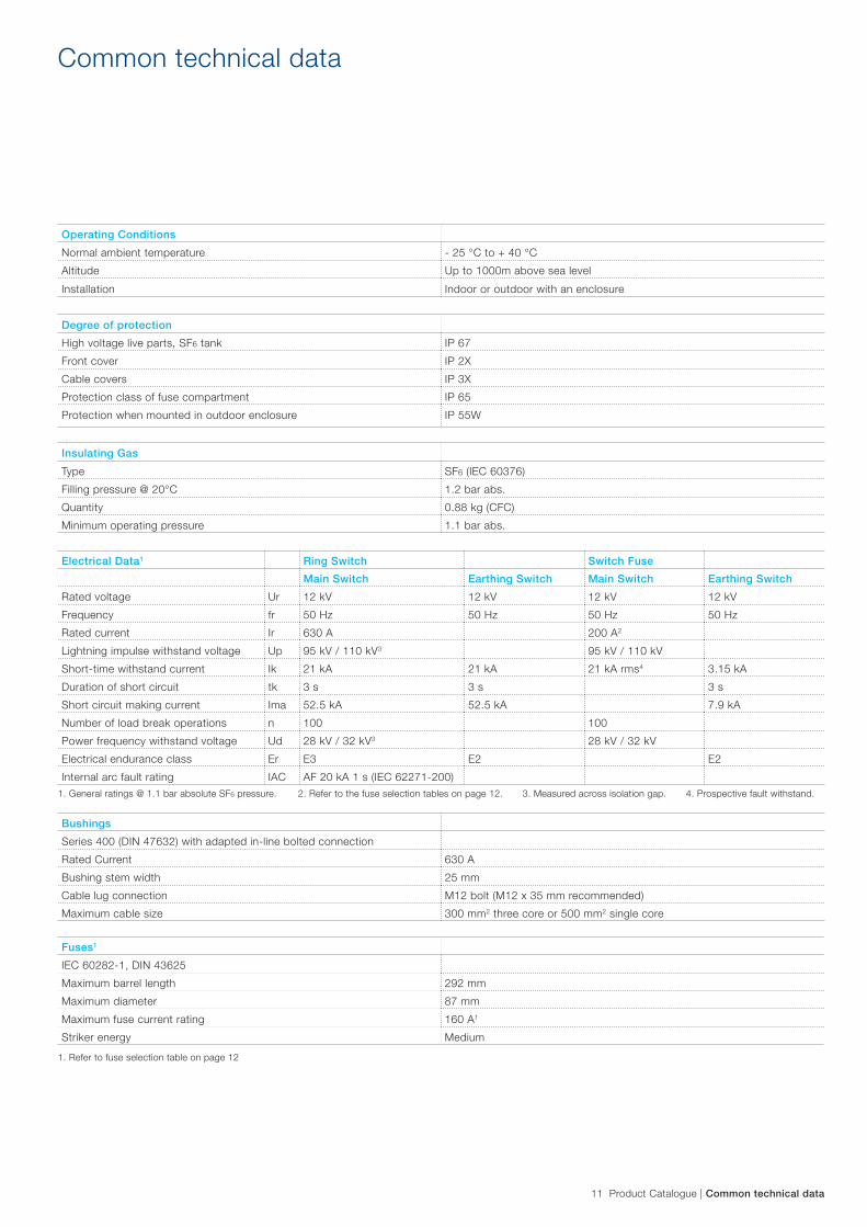
11 Product Catalogue | Common technical data
Operating ConditionsNormal ambient temperature - 25 °C to + 40 °CAltitude Up to 1000m above sea levelInstallation Indoor or outdoor with an enclosure
Degree of protection High voltage live parts, SF6 tank IP 67Front cover IP 2XCable covers IP 3XProtection class of fuse compartment IP 65Protection when mounted in outdoor enclosure IP 55W
Insulating GasType SF6 (IEC 60376)Filling pressure @ 20°C 1.2 bar abs.Quantity 0.88 kg (CFC)Minimum operating pressure 1.1 bar abs.
Electrical Data1 Ring Switch Switch FuseMain Switch Earthing Switch Main Switch Earthing Switch
Rated voltage Ur 12 kV 12 kV 12 kV 12 kVFrequency fr 50 Hz 50 Hz 50 Hz 50 HzRated current Ir 630 A 200 A2
Lightning impulse withstand voltage Up 95 kV / 110 kV3 95 kV / 110 kVShort-time withstand current Ik 21 kA 21 kA 21 kA rms4 3.15 kADuration of short circuit tk 3 s 3 s 3 sShort circuit making current Ima 52.5 kA 52.5 kA 7.9 kANumber of load break operations n 100 100Power frequency withstand voltage Ud 28 kV / 32 kV3 28 kV / 32 kVElectrical endurance class Er E3 E2 E2Internal arc fault rating IAC AF 20 kA 1 s (IEC 62271-200)
1. General ratings @ 1.1 bar absolute SF6 pressure.
1. Refer to fuse selection table on page 12
2. Refer to the fuse selection tables on page 12. 3. Measured across isolation gap. 4. Prospective fault withstand.
BushingsSeries 400 (DIN 47632) with adapted in-line bolted connectionRated Current 630 ABushing stem width 25 mmCable lug connection M12 bolt (M12 x 35 mm recommended)Maximum cable size 300 mm2 three core or 500 mm2 single core
Fuses1
IEC 60282-1, DIN 43625 Maximum barrel length 292 mmMaximum diameter 87 mmMaximum fuse current rating 160 A1
Striker energy Medium
Common technical data
12 Product Catalogue | Common technical data
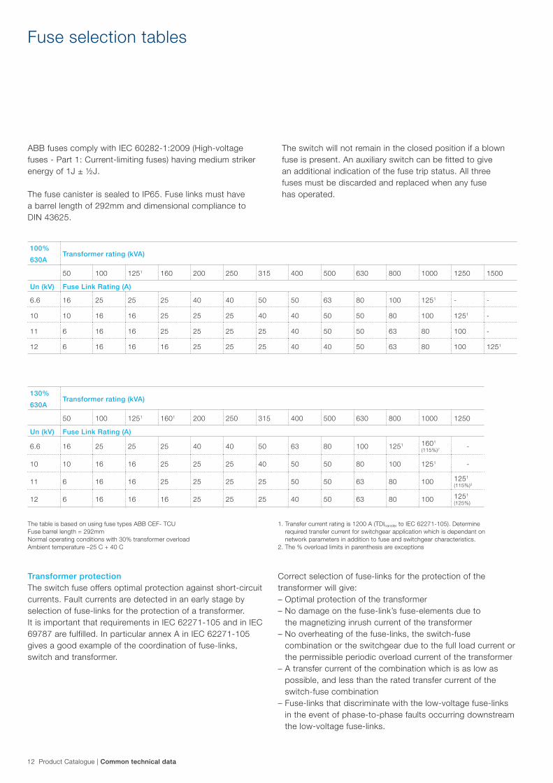
ABB fuses comply with IEC 60282-1:2009 (High-voltage fuses - Part 1: Current-limiting fuses) having medium striker energy of 1J ± ½J.
The fuse canister is sealed to IP65. Fuse links must have a barrel length of 292mm and dimensional compliance to DIN 43625.
Fuse selection tables
130%630A
Transformer rating (kVA)
50 100 1251 1601 200 250 315 400 500 630 800 1000 1250
Un (kV) Fuse Link Rating (A)
6.6 16 25 25 25 40 40 50 63 80 100 1251 1601 (115%)2 -
10 10 16 16 25 25 25 40 50 50 80 100 1251 -
11 6 16 16 25 25 25 25 50 50 63 80 100 1251 (115%)2
12 6 16 16 16 25 25 25 40 50 63 80 100 1251 (125%)
The table is based on using fuse types ABB CEF- TCUFuse barrel length = 292mmNormal operating conditions with 30% transformer overloadAmbient temperature –25 C + 40 C
100%630A
Transformer rating (kVA)
50 100 1251 160 200 250 315 400 500 630 800 1000 1250 1500
Un (kV) Fuse Link Rating (A)
6.6 16 25 25 25 40 40 50 50 63 80 100 1251 - -
10 10 16 16 25 25 25 40 40 50 50 80 100 1251 -
11 6 16 16 25 25 25 25 40 50 50 63 80 100 -
12 6 16 16 16 25 25 25 40 40 50 63 80 100 1251
The switch will not remain in the closed position if a blown fuse is present. An auxiliary switch can be fitted to give an additional indication of the fuse trip status. All three fuses must be discarded and replaced when any fuse has operated.
Transformer protectionThe switch fuse offers optimal protection against short-circuit currents. Fault currents are detected in an early stage by selection of fuse-links for the protection of a transformer. It is important that requirements in IEC 62271-105 and in IEC 69787 are fulfilled. In particular annex A in IEC 62271-105 gives a good example of the coordination of fuse-links, switch and transformer.
Correct selection of fuse-links for the protection of the transformer will give:– Optimal protection of the transformer– No damage on the fuse-link’s fuse-elements due to
the magnetizing inrush current of the transformer– No overheating of the fuse-links, the switch-fuse
combination or the switchgear due to the full load current or the permissible periodic overload current of the transformer
– A transfer current of the combination which is as low as possible, and less than the rated transfer current of the switch-fuse combination
– Fuse-links that discriminate with the low-voltage fuse-links in the event of phase-to-phase faults occurring downstream the low-voltage fuse-links.
1. Transfer current rating is 1200 A (TDItransfer to IEC 62271-105). Determine required transfer current for switchgear application which is dependant on network parameters in addition to fuse and switchgear characteristics.
2. The % overload limits in parenthesis are exceptions
13 Product Catalogue | Automation
Automation
SafeLink 2 Automation is an optional system designed for controlling and monitoring the switchgear.
Key functions of SafeLink 2 Automation– Remote switch position indication for both ring and
fuse switches– Remote control for ring switches when motor drive units
are fitted– Real time ring current and voltage measurement on all
three phases– Directional earth fault and phase to phase fault detection
SafeLink 2 Automation is powered by a 24 Vdc battery backed power supply. AC supply, DC output, current flow, battery condition testing and system failure alarms are some of the many points controlled and monitored via Modbus from the RTU.
SafeLink 2 Automation requires a 230Vac, 50 Hz supply. An IP 66 rated 3 pin plug and connector are provided to connect mains power to the automation control box.
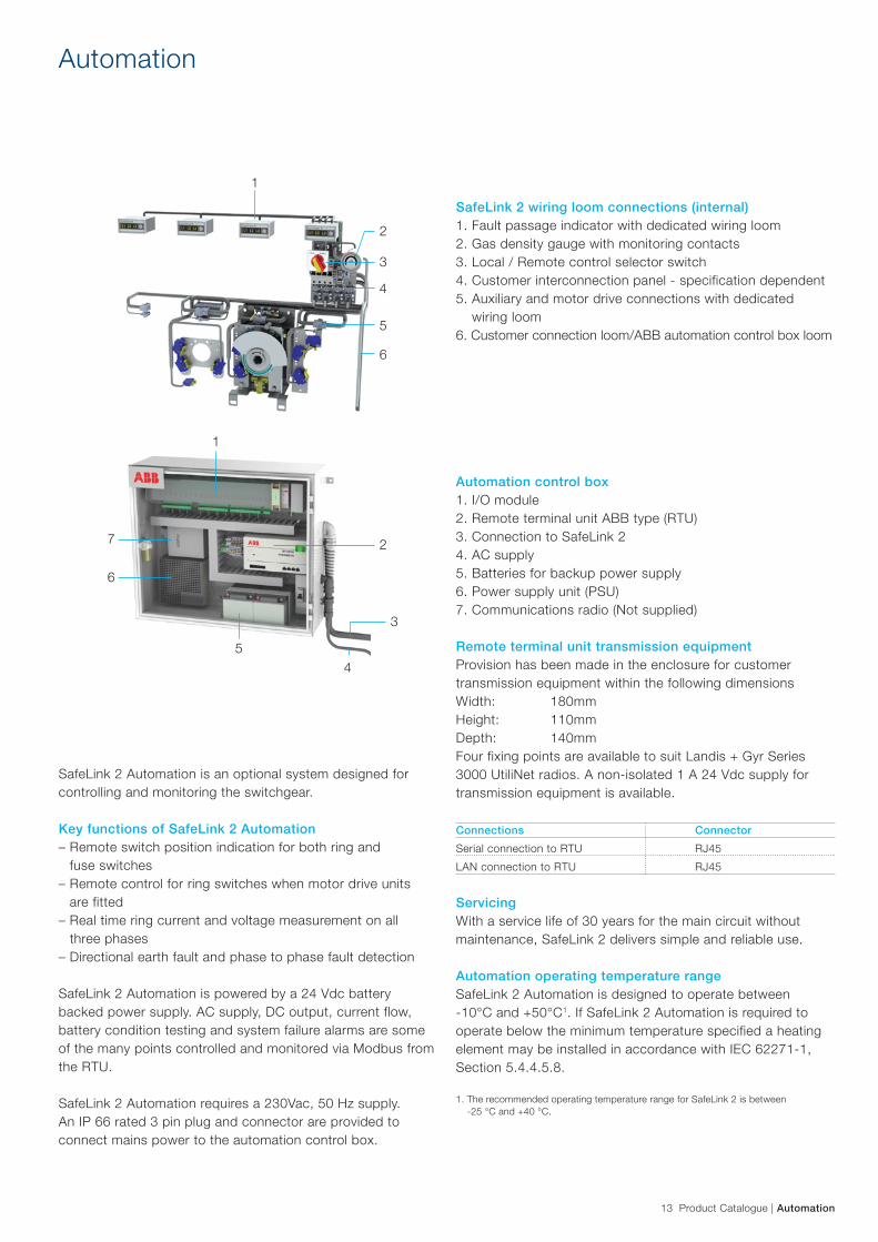
SafeLink 2 wiring loom connections (internal)1. Fault passage indicator with dedicated wiring loom2. Gas density gauge with monitoring contacts3. Local / Remote control selector switch4. Customer interconnection panel - specification dependent5. Auxiliary and motor drive connections with dedicated
wiring loom6. Customer connection loom/ABB automation control box loom
Automation control box1. I/O module2. Remote terminal unit ABB type (RTU)3. Connection to SafeLink 24. AC supply5. Batteries for backup power supply6. Power supply unit (PSU)7. Communications radio (Not supplied)
Remote terminal unit transmission equipmentProvision has been made in the enclosure for customer transmission equipment within the following dimensionsWidth: 180mmHeight: 110mmDepth: 140mmFour fixing points are available to suit Landis + Gyr Series 3000 UtiliNet radios. A non-isolated 1 A 24 Vdc supply for transmission equipment is available.
Connections ConnectorSerial connection to RTU RJ45LAN connection to RTU RJ45
ServicingWith a service life of 30 years for the main circuit without maintenance, SafeLink 2 delivers simple and reliable use.
Automation operating temperature rangeSafeLink 2 Automation is designed to operate between -10°C and +50°C1. If SafeLink 2 Automation is required to operate below the minimum temperature specified a heating element may be installed in accordance with IEC 62271-1, Section 5.4.4.5.8.
1. The recommended operating temperature range for SafeLink 2 is between -25 °C and +40 °C.
1
3
2
4
5
6
27
3
6
1
54
14 Product Catalogue | Optional features
Optional features
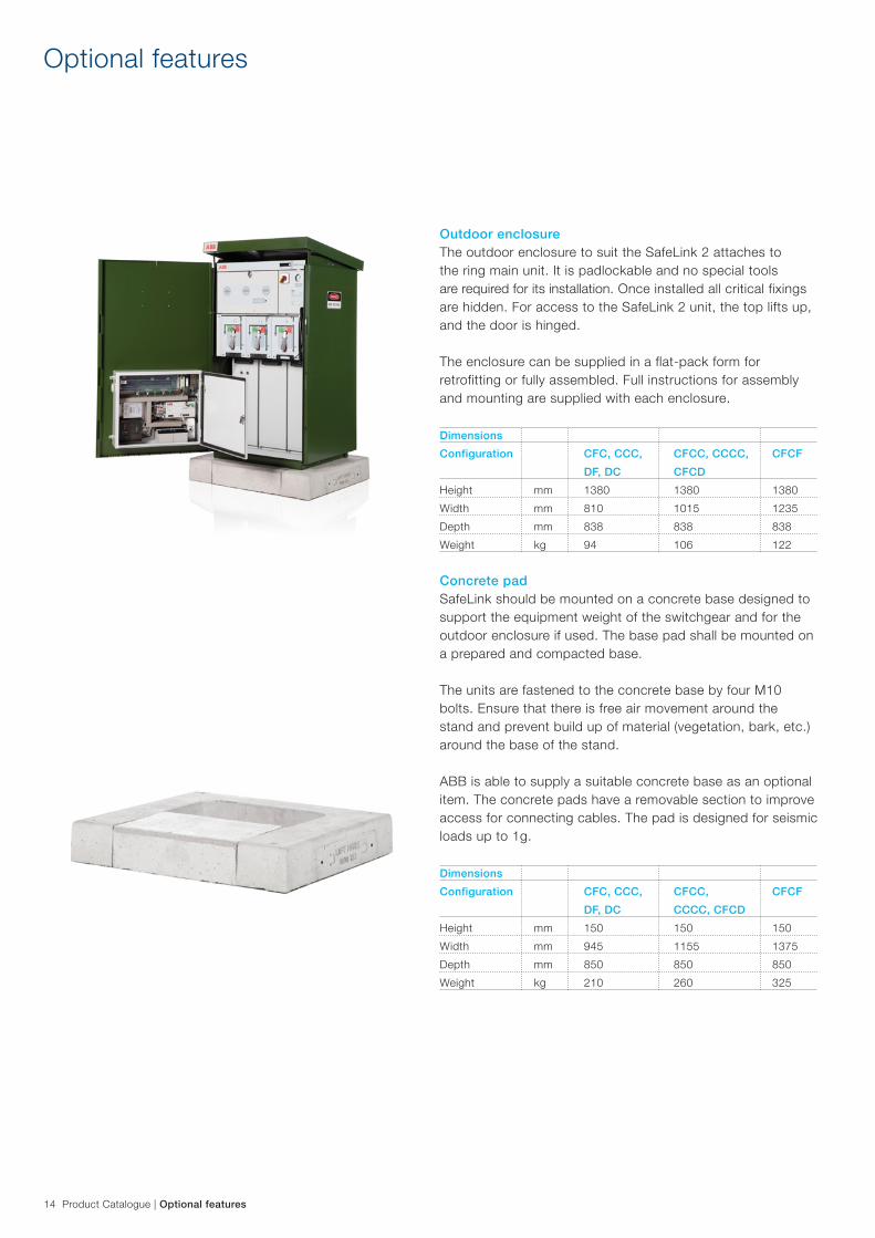
Outdoor enclosureThe outdoor enclosure to suit the SafeLink 2 attaches to the ring main unit. It is padlockable and no special tools are required for its installation. Once installed all critical fixings are hidden. For access to the SafeLink 2 unit, the top lifts up, and the door is hinged.
The enclosure can be supplied in a flat-pack form for retrofitting or fully assembled. Full instructions for assembly and mounting are supplied with each enclosure.
DimensionsConfiguration CFC, CCC, CFCC, CCCC, CFCF DF, DC CFCDHeight mm 1380 1380 1380Width mm 810 1015 1235Depth mm 838 838 838Weight kg 94 106 122
Concrete padSafeLink should be mounted on a concrete base designed to support the equipment weight of the switchgear and for the outdoor enclosure if used. The base pad shall be mounted on a prepared and compacted base.
The units are fastened to the concrete base by four M10 bolts. Ensure that there is free air movement around the stand and prevent build up of material (vegetation, bark, etc.) around the base of the stand.
ABB is able to supply a suitable concrete base as an optional item. The concrete pads have a removable section to improve access for connecting cables. The pad is designed for seismic loads up to 1g.
DimensionsConfiguration CFC, CCC, CFCC, CFCF DF, DC CCCC, CFCDHeight mm 150 150 150Width mm 945 1155 1375Depth mm 850 850 850Weight kg 210 260 325
15 Product Catalogue | Optional features
SIGMA F+E 3 short-circuit and earth fault indicatorThe SIGMA F+E 3 provides short-circuit and earth fault indication with relay outputs for remote monitoring. Includes three cable bushing mounted current transformers for short circuit and earth fault detection.
Trip currents (Ik) adjustable to 200, 300, 400, 600, 800, 1000 or 2000A, or self-adjusting
Trip currents (Io) adjustable to 20, 40, 60, 80, 100, 120 or 400 AResponse delay (Ik/Io) 40, 80, 200, 300 ms/ 80, 160, 200, 300 msTimed reset after passage of 1, 2, 4 or 8 hRemote test/remote reset via external potential-free momentary contactEnergy supply Long-life lithium cell, life expectancy 20 years,
total flashing time >1000hRelay contact permanent or momentary contact (1s), adjustable
Note: The Sigma F+E 3 is a minimum fault passage indication requirement for plug and play capability on automation enabled (AE) units.
ComPass B directional short-circuit and directional earth fault indicatorThe ComPass B provides directional detection of short-circuits and directional detection of earth faults, indication of load flow direction, and neutral earth connections. Connection to automation is available through Modbus. Includes three cable bushing mounted current transformers.
Trip currents (Ik/Io) 50 A - 2000 A / 20 A - 1000 ADelay time (Ik/Io) 40 ms < t < 60 msTimed reset after passage of 1, 2, 4 or 8 hRemote test/remote reset via external potential-free momentary contactEnergy supply External: by 24 - 230V AC/DC; internal:
by back-up supplyRelay contact permanent or momentary contact (1s), selectable
Note: A voltage indication cable connecting to the VPIS is supplied for directional fault indication.
DJ-3100 short-circuit and earth fault indicatorThe DJ-3100 provides detection of short-circuits and earth fault indications. Includes three cable bushing mounted current transformers for short circuit detection and one cable mounted current transformer for earth fault protection.
Trip currents (Ik) 150 A - 2000 AEarth fault currents (I0) 10A – 60 A ± 1 ADelay time (Ik/I0) 40 ms < t < 60 msTimed reset after passage of 7 s, 1, 2, or 4 hTest/reset reset via external potential-free momentary contactEnergy supply Internal: by long life lithium cell 3.6 V / 2.45 Ah
Optional features
16 Product Catalogue | Optional features
Optional features
Phase comparator type PCMThe PCM-phase comparator indicates phase balance /unbalance between two modules. To be used in capacitive coupling systems, acc. to IEC 61243-5 and/or IEC 62271-206.
Before closing a new incoming feeder or ring current to a live SafeLink 2 ring main unit, check phase balance with the phase comparator.
Special featuresNo external power supply required.Voltage indication by flashing LED.Fully insulated system (IP 68) with cast resin.
Technical data VIM 3Rated frequency 50 / 60 HzThreshold voltage U 70 - 90VThreshold current I 1,62 - 2,5 µACapacity to coupling system 74 - 88 pFInput impedance of indicator 36 - 43,2 MOhmEnclosure protection IP 68Dimensions VIM 3, w x h x d, excl. connectors 144 x 28 x 30 mm
Remote LED indicatorThis module gives a bright red LED indication if there is a fault.
The module is mounted on the inside of the enclosure door in such a way that it is visible externally.
17 Product Catalogue | Optional features
Optional features
AutomationConfigurable solutions determined by customer choice of components and looms– Customer interface panel choice for required level of
monitoring or automation– 1 common wiring loom for each monitoring device– 1 common wiring loom for each auxiliary switch or motor drive– Local/Remote selector located on low voltage
compartment door– One common automation system for both 3 and 4 way
RMUs with common looms
Automation control box– 1 common wiring loom connection to control box and RTU
for power supply, SF6 monitoring, local/remote indication and Modbus signals
– Plug-in control box that houses battery and automation control box can be supplied to fit within the outdoor enclosure space
For more information see page 13.
Motor drive– Demountable modular assembly able to be fitted to any
ring switch– Fitted behind mimic panel– Two auxiliary switches per switch position– Integral contactor control, wiring loom and plug connection– 24Vdc operation– Manual override is standard
Auxiliary switchSnap action double-break switch with forced contact opening and self–cleaning contacts.
– 1 x Normally Open contact and 1 x Normally Closed contact per block.
– Auxiliary switch can be fitted to ring switches and switch fuses.
Note: Motor drives have their own switch position switches fitted. Auxiliary switches for fuse trip indication are available.
Ratings Ith A 10Vac V 380Vdc V 450V withstand V 2500
18 Product Catalogue | Optional features
Optional features
Shunt trip– Available in 24Vdc and 230 Vac – The shunt trip can be retrofitted to any fuse switch combination
SF6 gas pressure monitor with auxiliary contactsThis monitor is a direct replacement for the standard gauge.
There are two sets of contacts built into the gauge.
The first stage contact opens when the pressure drops to 1.15 bar indicating reduced gas. The second stage contact opens when the pressure drops to 1.1 bar or below and provides a signal that can be used for remote operation lockout.
Gas filling/sampling adaptor kitThe gas filling/sampling adaptor kit allows access to the SF6 gas tank via the density gauge shut-off connecting valve.
Fitted with ¼ NPT nipple for connection to bottle regulator set (not supplied).
Extended height plinthExtends the height by 300mmFits to the base of the RMUAvailable in three sizes to suit width of the RMU
Additional tank protectionA SafeLink 2 model is available upon request where the 304L stainless steel tank has a protective coating to provide additional protection in corrosive environments. A top cover is also fitted to the top of the tank yet does not affect the overall dimensions.
19 Product Catalogue | Optional features
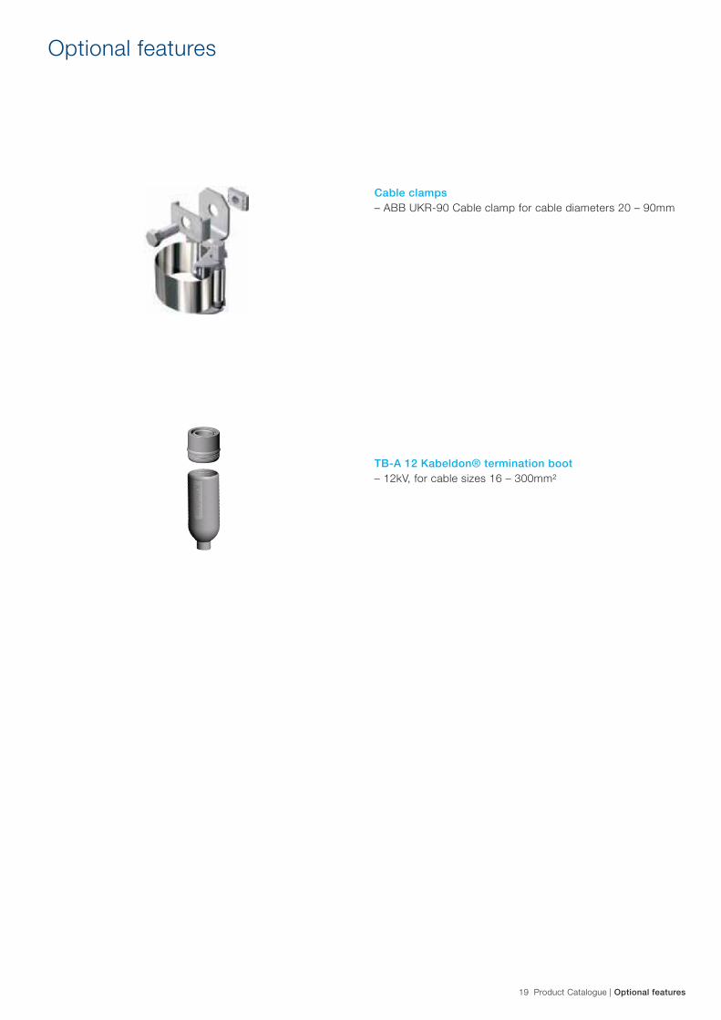
Cable clamps– ABB UKR-90 Cable clamp for cable diameters 20 – 90mm
TB-A 12 Kabeldon® termination boot– 12kV, for cable sizes 16 – 300mm²
Optional features

20 Product Catalogue | Dimensions – 2-way / 3-way
Dimensions – 2-way / 3-way
Configuration CFC, CCC / DF, DCHeight1 mm 1352Width mm 709Depth mm 699Weight kg 285
1 Extended height plinths are available to increase standard height to 1650mm
628
110
ARC PRODUCT CHIMNEY ADDED
CHIMNEY PLUS ABSORBER ADDED
SECTION A-A
STANDARD UNIT FRONT VIEW
3013
9910
0
144
200
205 205
200
60
100
709
1352
A A
699
645
Document Identity
Filename Project:
Jurgens Wolfaardt Harri Laitinen Released
26/07/2012 27/07/2012
CFC General Arrangement SL2
D
E
F
1 2
C
321 4
B
A
5 6
C
A
B
1
E
7 8
3We
rese
rve
all r
ight
s in
this
doc
umen
t and
in th
e in
form
atio
n co
ntai
ned
ther
ein.
Rep
rodu
ctio
n, u
se o
r di
sclo
sure
to th
irdpa
rtie
s w
ithou
t exp
ress
aut
horit
y is
str
ictly
forb
idde
n. ©
AB
B L
td, P
TP
M, 1
33 C
entr
al P
ark
Driv
e, A
uckl
and,
New
Zea
land
.
Scale: 1:10
4 5
F
Paper Size
Lang
Date Checked
Status Author
Supplementary Title (Line 2)
PPMV
ECN#
A3
D
Supplementary Title
Document kind
1ABB Responsible Department/ Company
Date Created
Sheet
Checked by
EN
Projection: 3rd Angle
Date Effective
Title
of
Rev
CFC General Arrangement SL2
All dimensions in mm.Unless stated tolerances are: Linear: ± 0.25 Drilled Holes: +0.14 - 0 Reamed Holes: + 0.03 - 0 Angular: ± 1
SafeLink 2
732AFL SIDECOVERS ADDED
750
805
Left Hand View(end panel removed)
Front View
Foundation View (Section AA)
CFC, CCC, DF, DC
1056
Front View
Foundation View(section A-A)
1138
1352
A A
26/07/2012
E
F
1 2
C
321 4
B
5 6
C
A
B
D
E
3We
rese
rve
all r
ight
s in
this
doc
umen
t and
in th
e in
form
atio
n co
ntai
ned
ther
ein.
Rep
rodu
ctio
n, u
se o
r di
sclo
sure
to th
ird
Euan Hyndman
D
A3 Date Created
Sheet
Checked by
EN
Date Effective
Title
of Document kind
CFCF General Arrangement SL2
Responsible Department/ Company Rev
1
part
ies
with
out e
xpre
ss a
utho
rity
is s
tric
tly fo
rbid
den.
© A
BB
Ltd
, PP
MV
, 133
Cen
tral
Par
k D
rive,
Auc
klan
d, N
ew Z
eala
nd.
Angular: ± 1 27/07/2012
Harri Laitinen
PPMV
SafeLink 2
5
ABB 1 Document Identity
Filename4
8
A
7
Scale: 1:10
Supplementary Title (Line 2)
Released F Paper Size
Lang
Date Checked
Status Author
contact the Author of the last revision.
Project:
Supplementary Title
All dimensions in mm.Unless stated tolerances are: Linear: ± 0.25 Drilled Holes: +0.14 - 0 Reamed Holes: + 0.03 - 0
If in doubt of any information, please A
Left Hand View(end panel removed)
699
645
200
100
198
60
144
30
365
99
199
100
220
200
13 TYPICAL
26/07/2012 4:24 p.m.
21 Product Catalogue | Dimensions – 4-way / CFCF
Dimensions – 4-way / CFCF
832
SECTION A-A
222196 196
30
13
200
200
144
9810
010
0
60144(end panel removed)Left Hand View
Foundation View
645
699
Front View
910
1352
A A
Rev
1 Document kind
Supplementary Title
1 Document Identity
Filename Project:
SafeLink 2
CFCC General Arrangement SL2
26/07/2012
ReleasedBrent Knox
27/07/2012
D
E
F
1 2
C
32
Responsible Department/ Company
4
B
A
5 6
C
A
B
D
E
7
Harri Laitinen
3We
rese
rve
all r
ight
s in
this
doc
umen
t and
in th
e in
form
atio
n co
ntai
ned
ther
ein.
Rep
rodu
ctio
n, u
se o
r di
sclo
sure
to th
irdpa
rtie
s w
ithou
t exp
ress
aut
horit
y is
str
ictly
forb
idde
n. ©
AB
B L
td, P
PM
V, 1
33 C
entr
al P
ark
Driv
e, A
uckl
and,
New
Zea
land
.
Scale: 1:10
4 5
1
CFCC General Arrangement SL2
8
of
Title
Print DateF
Paper Size
Lang
Date Checked In
Status Author
Supplementary Title (Line 2)
ECN#
A3 Date Created
Sheet
Checked by
EN
Projection: 3rd Angle
All dimensions in mm.Unless stated tolerances are: Linear: ± 0.25 Drilled Holes: +0.14 - 0 Reamed Holes: + 0.03 - 0 Angular: ± 1
PPMV
1056
Front View
Foundation View(section A-A)
1138
1352
A A
26/07/2012
E
F
1 2
C
321 4
B
5 6
C
A
B
D
E
3We
rese
rve
all r
ight
s in
this
doc
umen
t and
in th
e in
form
atio
n co
ntai
ned
ther
ein.
Rep
rodu
ctio
n, u
se o
r di
sclo
sure
to th
ird
Euan Hyndman
D
A3 Date Created
Sheet
Checked by
EN
Date Effective
Title
of Document kind
CFCF General Arrangement SL2
Responsible Department/ Company Rev
1
part
ies
with
out e
xpre
ss a
utho
rity
is s
tric
tly fo
rbid
den.
© A
BB
Ltd
, PP
MV
, 133
Cen
tral
Par
k D
rive,
Auc
klan
d, N
ew Z
eala
nd.
Angular: ± 1 27/07/2012
Harri Laitinen
PPMV
SafeLink 2
5
ABB 1 Document Identity
Filename4
8
A
7
Scale: 1:10
Supplementary Title (Line 2)
Released F Paper Size
Lang
Date Checked
Status Author
contact the Author of the last revision.
Project:
Supplementary Title
All dimensions in mm.Unless stated tolerances are: Linear: ± 0.25 Drilled Holes: +0.14 - 0 Reamed Holes: + 0.03 - 0
If in doubt of any information, please A
Left Hand View(end panel removed)
699
645
200
100
198
60
144
30
365
99
199
100
220
200
13 TYPICAL
26/07/2012 4:24 p.m.
832
SECTION A-A
222196 196
30
13
200
200
144
9810
010
0
60144(end panel removed)Left Hand View
Foundation View
645
699
Front View
910
1352
A A
Rev
1 Document kind
Supplementary Title
1 Document Identity
Filename Project:
SafeLink 2
CFCC General Arrangement SL2
26/07/2012
ReleasedBrent Knox
27/07/2012
D
E
F
1 2
C
32
Responsible Department/ Company
4
B
A
5 6
C
A
B
D
E
7
Harri Laitinen
3We
rese
rve
all r
ight
s in
this
doc
umen
t and
in th
e in
form
atio
n co
ntai
ned
ther
ein.
Rep
rodu
ctio
n, u
se o
r di
sclo
sure
to th
irdpa
rtie
s w
ithou
t exp
ress
aut
horit
y is
str
ictly
forb
idde
n. ©
AB
B L
td, P
PM
V, 1
33 C
entr
al P
ark
Driv
e, A
uckl
and,
New
Zea
land
.
Scale: 1:10
4 5
1
CFCC General Arrangement SL2
8
of
Title
Print DateF
Paper Size
Lang
Date Checked In
Status Author
Supplementary Title (Line 2)
ECN#
A3 Date Created
Sheet
Checked by
EN
Projection: 3rd Angle
All dimensions in mm.Unless stated tolerances are: Linear: ± 0.25 Drilled Holes: +0.14 - 0 Reamed Holes: + 0.03 - 0 Angular: ± 1
PPMV
Left Hand View(end panel removed)
Left Hand View(end panel removed)
Front View
Front View
Foundation View (Section AA)
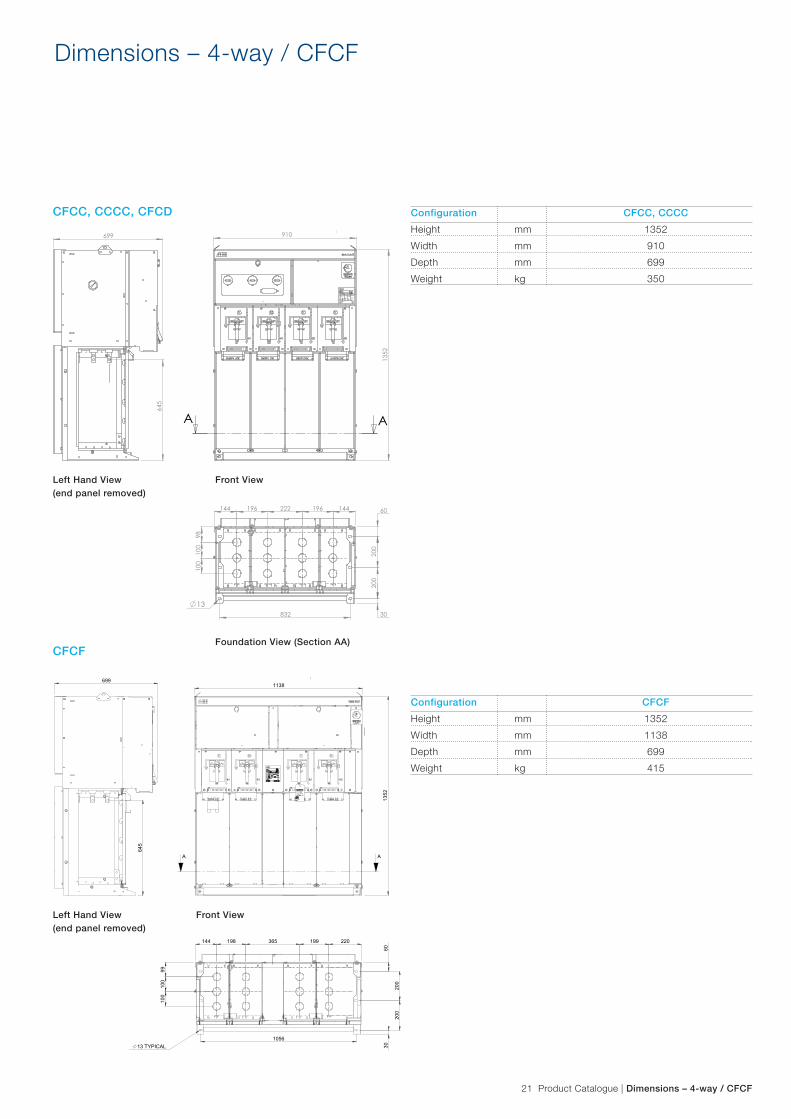
Configuration CFCC, CCCCHeight mm 1352Width mm 910Depth mm 699Weight kg 350
Configuration CFCFHeight mm 1352Width mm 1138Depth mm 699Weight kg 415
CFCC, CCCC, CFCD
CFCF
22 Product Catalogue | Standards
Standards
Codes and standardsSafeLink 2 is manufactured and tested in accordance with the latest version of the following IEC standards.
IEC 62271-1 High – voltage switchgear and control gear, common specificationsIEC 62271-102 Alternating current disconnectors and earthing switchesIEC 62271-105 Alternating current switch-fuse combinationsIEC 62271-200 A.C. metal-enclosed switchgear and control gear for rated voltages above 1kV and up to and including 52 kVIEC 60265-1 (1998-01) High-voltage switches - Part 1: Switches for rated voltages above 1kV and less than 52 kVIEC 60137 (1995-12) Insulating bushings for alternating voltages above 1000 VIEC 60529 (1989-11) Degrees of protection provided by enclosures (IP Code)62271-206 Voltage presence indicating systems for rated voltages above 1 kV and up to and including 52 kV
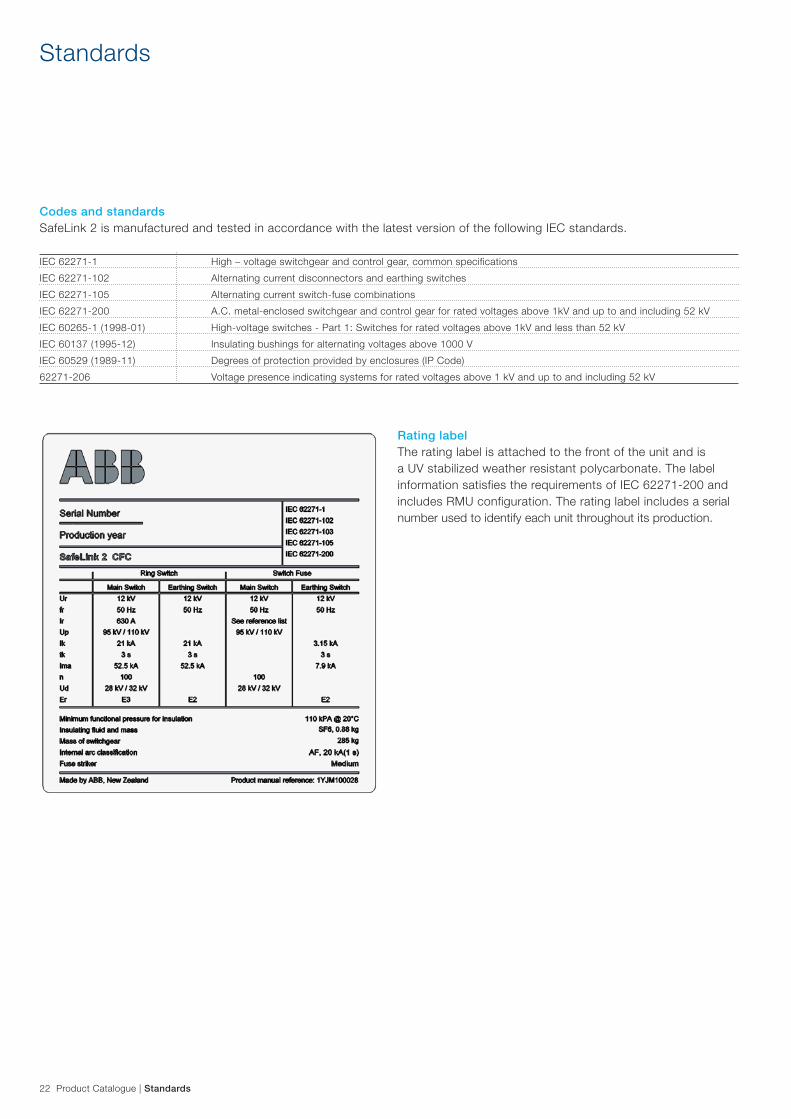
Rating labelThe rating label is attached to the front of the unit and is a UV stabilized weather resistant polycarbonate. The label information satisfies the requirements of IEC 62271-200 and includes RMU configuration. The rating label includes a serial number used to identify each unit throughout its production.
23 Product Catalogue | Maintenance
Maintenance
EnvironmentThe SafeLink 2 tank is a gas-tight welded stainless steel compartment. The tank is mounted on a hot dipped galvanized 4mm steel frame. The unit should be kept free of vegetation or other material to prevent corrosion of the stand and/or enclosure.
Additional protection against tank corrosion is available, see page 18.
The mass of SF6 placed into the SafeLink 2 equipment at the time of filling is approximately as follows:
Configuration MassCFC, CCC kg 0.88, 0.95CFCC, CCCC kg 1.1, 1.2CFCF kg 1.3
SF6 GasABB has SF6 recycling facilities available. For more information on SF6, visit http://www.abb.com/sf6
MaintenanceAll components within the SF6 insulated tank are maintenance free for the life expectancy of the unit.
Scratches or other damage to panels must be repaired.
Mechanical parts located outside the sealed tank are surface treated or made of corrosion resistant materials.
Units installed in harsh environments will require regular operation and maintenance. Maintenance includes cleaning the unit and inspection for and repair of corrosion. The maintenance interval is dependent on the atmospheric corrosivity category specified in EN ISO 12944 part 2. For the correct maintenance intervals contact ABB. For added tank protection in harsh environments see page 18.
The outdoor enclosure is fabricated from marine grade aluminium with a powder coated finish. The base of the stand must be kept clear of vegetation and other materials.
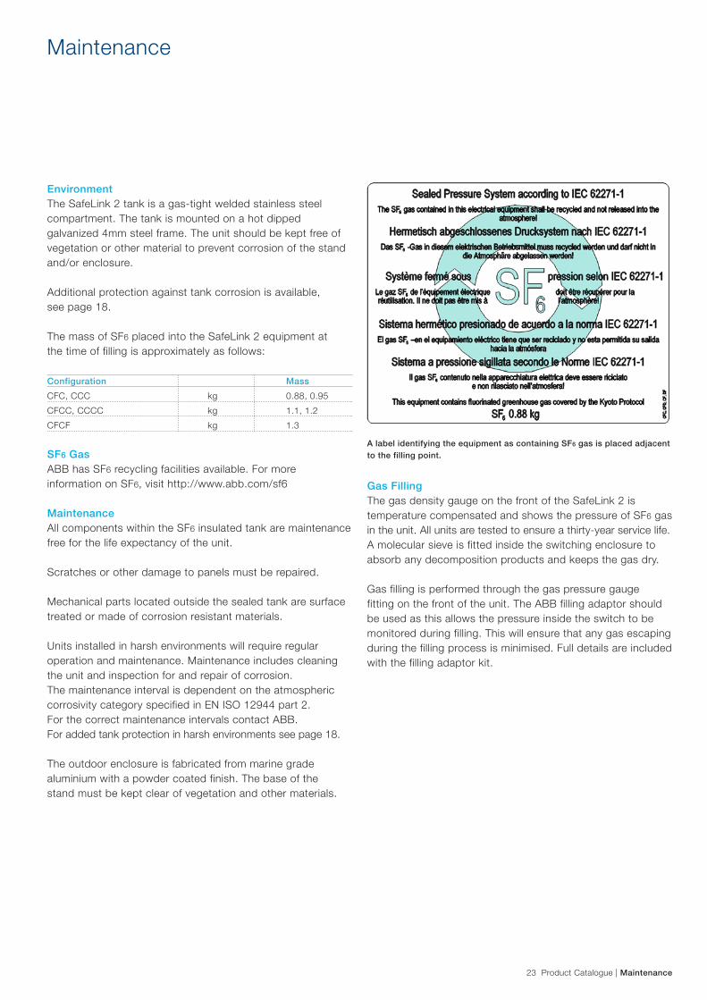
A label identifying the equipment as containing SF6 gas is placed adjacent to the filling point.
Gas FillingThe gas density gauge on the front of the SafeLink 2 is temperature compensated and shows the pressure of SF6 gas in the unit. All units are tested to ensure a thirty-year service life. A molecular sieve is fitted inside the switching enclosure to absorb any decomposition products and keeps the gas dry.
Gas filling is performed through the gas pressure gauge fitting on the front of the unit. The ABB filling adaptor should be used as this allows the pressure inside the switch to be monitored during filling. This will ensure that any gas escaping during the filling process is minimised. Full details are included with the filling adaptor kit.
83
104
Project:
D
E
F
1 2
C
321 4
B
A
5 6
C
A
B
D
E
7 8
3
Finish - Matt Velvet
Angular: ± 1
Scale: 2:1
4 5
F
part
ies
with
oute
xpre
ssau
thor
ityis
stric
tlyfo
rbid
den.
©A
BB
Ltd,
PP
MV
,133
Cen
tral
Par
kD
rive,
Auc
klan
d,N
ewZ
eala
nd.
SafeLink 2 Lang
Date Checked In
Paper Size
A
Author Status
Jurgens Wolfaardt ECN#
A3 Date Created
Sheet
Checked by
EN
Projection: 3rd Angle
We
rese
rve
allr
ight
sin
this
docu
men
tand
inth
ein
form
atio
nco
ntai
ned
ther
ein.
Rep
rodu
ctio
n,us
eor
disc
losu
reto
third
Released
Euan Hyndman
Harri Laitinen
Production ReleaseA
Print Date
Title
of
29/05/2012 Supplementary Title (Line 2)
LABEL SF6 WARNING CFC, CFD, CF & DF SL2
Responsible Department/ Company Rev
1 Document kind
Supplementary Title
2
3719
Document Identity
27/07/2012
Filename
PPMV
Date Revision Details Author
Based on 1VB8000077
C544827/07/2012
All dimensions in mm.Unless stated tolerances are: Linear: ± 0.25 Drilled Holes: +0.14 - 0 Reamed Holes: + 0.03 - 0
Material - 175µm polycarbonate with 3M 468 permanent adhesive backing
24 Product Catalogue | Environmental declaration
Environmental declaration
The product complies with the requirements denoted by IEC 62271-200.
ABB is committed to the protection of the environment and adheres to ISO 14001 standards. It is our obligation to facilitate end-of-life recycling for our products. ABB can arrange to reclaim SF6 gas from discarded switchgears for recycling.
There are no explicit requirements for how to handle discarded switchgears at end-of-life. ABB’s recycling service is according to IEC 62271-303:2008 section 10: {End of life SF6 filled equipment}. No special action is required; non-recoverable parts can be disposed of normally according to local regulations
The switchgear is gas-tight with an expected diffusion rate of less than 0.1% per annum. Referring to the reference-pressure of 1.2 bar, the switchgear will maintain gas-tightness and a gas-pressure better than 1.1 bar* throughout its designed life span (* at 20°C). The designed life span under indoor service condition exceeds 30 years.
1. Based a CFC configuration
Raw Material Weight % of total weight Recycle Environmental effects & recycle/reuse processes (kg) Steel (incl. Stainless) 195 77% Yes Separate and (re)meltCopper 27 10% Yes Separate and (re)meltZinc 6 2% Yes Separate and (re)meltBrass 2 1% Yes Separate and (re)meltSilver 0.1 0.03% Yes Separate and (re)meltThermoplastic 4 1% Yes Separate and make pellets or burn for energyRubber 1.5 1% Yes Burn for energySF6 gas 0.88 0.3% Yes ABB reclaims and recycles used SF6 gasTotal for recycling 235 93% Epoxy 18 7% Returns Returns 60% silicon ash if burned for energyEpoxy Resin Fibre 0.2 0.1% Landfill Total Weight1 253 100


Contact Us
ABB LimitedPower Products Division Medium Voltage ProductsPO Box 83203Edmonton Auckland 0652New ZealandTel: +64 9 837 1234Fax: +64 9 837 2950www.abb.co.nz/mediumvoltage
Text and illustrations are not binding.The right to make alterations is reserved.
© Copyright 2012 ABBAll rights reserved
1YJM
1000
27 E
N –
09.2
012