Product Bulletin ValveLink Software October 2012 ValveLink Software
16
www.Fisher.com ValveLink ™ Software ValveLink ™ Solo ValveLink ™ SNAP‐ON ™ ValveLink ™ DTM ValveLink ™ PLUG‐IN for PRM ® H Communicate with both HART ® and FOUNDATION ™ Fieldbus FIELDVUE ™ digital valve controllers H Configure, calibrate, and diagnose FIELDVUE instruments from one location H Use Stabilize & Optimize and Performance Tuner to easily optimize tuning H Performance Diagnostics provide in‐service diagnostics for monitoring the health of the valve assembly without disturbing the process H Diagnostics provide validation of assembly rebuild and detailed insight into the physical condition of the valve/actuator assembly H Setup and test FIELDVUE instruments for Safety Instrumented System (SIS) Solutions H Solenoid Valve Test to test and monitor the health of the solenoid connected to the valve assembly (SIS only) H Scheduler allows you to specify a time and date to automatically run tasks on a regular basis H Ability to preconfigure calibration and diagnostics in the workshop with Batch Runner or setup your own “Macro” file H Time saving Concurrent Batch allows executing a diagnostic test or Calibration on multiple valves at the same time H Merge Database feature provides the ability to automate multiple ValveLink databases and tags to a single or multiple stations H ValveLink Express licensing allows you to obtain a free version of ValveLink software that allows FIELDVUE instrument setup, calibration and verification H Generate diagnostic, calibration, and configuration reports in Microsoft ® Word and PDF format ValveLink Software D102227X012 Product Bulletin 62.1:ValveLink Software October 2017
Transcript of Product Bulletin ValveLink Software October 2012 ValveLink Software

www.Fisher.com
ValveLink™ Software
ValveLink™ Solo
ValveLink™ SNAP‐ON™
ValveLink™ DTM
ValveLink™ PLUG‐IN for PRM®
� Communicate with both HART® andFOUNDATION™ Fieldbus FIELDVUE™ digital valvecontrollers
� Configure, calibrate, and diagnose FIELDVUEinstruments from one location
� Use Stabilize & Optimize and PerformanceTuner to easily optimize tuning
� Performance Diagnostics provide in‐servicediagnostics for monitoring the health of thevalve assembly without disturbing theprocess
� Diagnostics provide validation of assemblyrebuild and detailed insight into the physicalcondition of the valve/actuator assembly
� Setup and test FIELDVUE instruments forSafety Instrumented System (SIS) Solutions
� Solenoid Valve Test to test and monitor thehealth of the solenoid connected to the valveassembly (SIS only)
� Scheduler allows you to specify a time anddate to automatically run tasks on a regularbasis
� Ability to preconfigure calibration anddiagnostics in the workshop with BatchRunner or setup your own “Macro” file
� Time saving Concurrent Batch allowsexecuting a diagnostic test or Calibration onmultiple valves at the same time
� Merge Database feature provides the abilityto automate multiple ValveLink databasesand tags to a single or multiple stations
� ValveLink Express licensing allows you toobtain a free version of ValveLink softwarethat allows FIELDVUE instrument setup,calibration and verification
� Generate diagnostic, calibration, andconfiguration reports in Microsoft® Wordand PDF format
ValveLink SoftwareD102227X012
Product Bulletin62.1:ValveLink Software
October 2017

ValveLink SoftwareD102227X012
Product Bulletin62.1:ValveLink SoftwareOctober 2017
2
ValveLink Software Product Suite
ValveLink software is available in a variety of configurations to allow you to realize the full benefit of FIELDVUE digitalvalve controllers.
ValveLink Solo
ValveLink Solo permits users to perform configuration, calibration, anddiagnostics on HART and FOUNDATION Fieldbus FIELDVUE digital valve controllers.
Integrate ValveLink software into AMS Device Manager
ValveLink SNAP‐ON provides integration with AMS Device Manager to performconfiguration, calibration, and diagnostics. Integration with AMS Device Managerprovides the ability to communicate with FIELDVUE digital valve controllers viaDeltaV�, Ovation�, PROVOX�, HART multiplexers, and HART modems.Non‐Emerson host integration, including Invensys and Honeywell (HART only)systems, can be provided through HSI (Host System Integration).
Integrate ValveLink DTM into Field Device Tool - FDT
ValveLink DTM provides integration into a Field Device Tool frame application toperform configuration, calibration, and diagnostics on FIELDVUE digital valvecontrollers. The ValveLink DTM is certified with the FDT group.
Integrate ValveLink Software into the Yokogawa Plant ResourceManager (PRM)
ValveLink PLUG‐IN for PRM provides integration with the Yokogawa PlantResource Manager (PRM). This integration provides PRM users with the ability tolaunch the ValveLink PLUG‐IN for PRM directly from PRM and to communicatewith HART and FOUNDATION fieldbus FIELDVUE digital valve controllers throughPRM and the Yokogawa CENTUM CS 3000 R3 and CENTRUM VP.

Trend Travel, Pressure, and Drive Signal
ValveLink SoftwareD102227X012
Product Bulletin62.1:ValveLink Software
October 2017
3
Communicate with both HART and FOUNDATION fieldbusFIELDVUE digital valve controllersIntegrated or standalone ValveLink software remotely communicates with HART FIELDVUE instruments over theexisting 4‐20 mA signal wiring using the HART communication standard. The same software also can communicatewith FOUNDATION Fieldbus FIELDVUE instruments over the fieldbus H1 segment. Information is presented in aconsistent, easy‐to‐interpret interface that provides the capability to configure, calibrate, and diagnose FIELDVUEinstruments from one location:
� Dashboard of critical instrument information
� A device connection view of all connected instruments
� Monitoring of instrument operational parameters and alerts, including Field Diagnostic alerts
� Review and comparison of diagnostic graphs
� Instrument setup and calibration
� Data import and export
� Schedule diagnostic tests
� Time-Saving tools such as Batch Runner and Concurrent Batch Runner

TREND VALVE TRAVEL AND PRESSURE
Alert categorization
Device alerts, such as Travel Deviation, are permanentlymapped to a Field Diagnostic Alert in FOUNDATION Fieldbusapplications. Multiple Field Diagnostic categories can be
selected per Field Diagnostic Alerts.
HART applications allow one Field DiagnosticCategory per Field Diagnostic Alert
Status Monitor
Status Monitor
IN THE FIELDON THE BENCH
ValveLink SoftwareD102227X012
Product Bulletin62.1:ValveLink SoftwareOctober 2017
4
Field Diagnostic Alerts, which follow the NAMUR NE107 Standard, allow categorization of Device Alerts with thehighest severity displayed on the dashboard.
Standalone ValveLink software can use the Emerson USB Fieldbus Interface, as well as the National Instruments(NI-Fbus) interface to connect to Fieldbus FIELDVUE instruments (DVC6200f and DVC6000f) to configure, calibrate,and diagnose the device on a bench or in the field:

Performance Diagnostics tests are available upon user request or a pre‐selected daily, weekly,monthly, or yearly schedule without user intervention for HART instruments
Performance Diagnostics are continually running in FOUNDATION Fieldbus Instrumentsand do not need to be initiated by ValveLink software
ValveLink SoftwareD102227X012
Product Bulletin62.1:ValveLink Software
October 2017
5
Use the Performance Tuner to easily optimize tuningThe Performance Tuner lets you easily adjust a FIELDVUE digital valve controller for optimum performance. Whenmounting a FIELDVUE digital valve controller, to either a Fisher or a non‐Fisher valve, the Performance Tuner canoptimize valve performance for you.
Performance Diagnostics provide in‐service diagnostics formonitoring the health of the valve assembly withoutdisturbing the process
Performance Diagnostics (PD) provides predictive in‐service diagnostics for monitoring the health of the valveassembly and customized diagnostics for advanced troubleshooting. Performance Diagnostics continuously analyzethe valve assembly and passively gather data without disturbing or interrupting the control valve while it is in theprocess.
PD may be used to help detect problems with air leakage, valve assembly friction and deadband, instrument airquality, loose connections, supply pressure restriction, and valve assembly calibration. When a problem is identified,the diagnostic provides a description and severity of the problem, a probable cause, and recommended action.
In‐service diagnostics for troubleshooting allow custom diagnostics to be set up to collect data at a high‐frequencycollection rate and present the data in a graphical format.

Performance Diagnostics provide on‐line/in‐servicepredictive diagnostics to identify faults and list possible
causes and recommended corrective actions for each fault
ValveLink SoftwareD102227X012
Product Bulletin62.1:ValveLink SoftwareOctober 2017
6
Provide Real‐Time Notification of Current and PotentialValve and Instrument Problems using PerformanceDiagnosticsPerformance Diagnosticsenable the use of diagnosticswhile the valve is in‐serviceand operating withoutdisturbing the process. Testscan be performed to identifyproblems with the entirecontrol valve assembly, suchas:
� Red/Yellow/Green condition indicator provides a quick visual indication of the following:
� the physical condition of the FIELDVUE instrument pneumatic components
� instrument air supply pressureand volume
� relay adjustment on double actingpiston actuators
� the total air received and used by the instrument, and
� why a valve assembly is deviatingfrom the set point
� PD One Button is a sweep of the above tests. When the sweep is complete, ValveLink software will show any errors, possible causes, and recommended actions to resolve the error(s).
� Friction and Deadband Trending
Performance Diagnostics tests are available upon userrequest or a pre‐selected daily, weekly, monthly, oryearly schedule without user intervention for HARTinstruments. Performance Diagnostics are continuallyrunning in Foundation Fieldbus Instruments and donot need to be initiated by ValveLink software.

Signature Analyzer Boundary Editor allows you to usedefault or customized test criteria
Diagnostic tests, such as the Valve Signature Diagnosticexample shown here, help you detect emerging valverepair requirements before they impact performance
ValveLink software enables simultaneousmultiple overlay of tests (up to ten). This
allows you to trend valve history.
ORIGINALTEST
NEWTEST
Zoom in to examine
valve movement and
other details
BOUNDARY RESULTS
PASS/FAIL RESULT
ValveLink SoftwareD102227X012
Product Bulletin62.1:ValveLink Software
October 2017
7
Provide validation of assembly rebuild and detailed insightinto the physical condition of the valve/actuator assembly
Performance Diagnostics monitor the digital valve controller set point and plot valve operation to provide insight intothe dynamic performance of the valve/actuator assembly. Out‐of‐service diagnostics such as valve signature, dynamicerror band, and step response assist in the identification of emerging valve problems quickly and accurately.
Use out-of-service diagnostics to prioritize and planmaintenance activities when the process is shut down.
The Valve Signature diagnostic is used to:
� Evaluate valve friction, deadband, and shutoff capability.
� Calculate actuator spring rate and bench set.
� Identify potential packing problems.
� Compare current condition to previous baseline condition.
� Signature Analyzer enables rapid analysis of the Valve Signature to more efficiently manage your plant assets. Based on default or user defined settings, Signature Analyzer provides pass/fail results for Maximum Friction, Minimum Friction, Stem Integrity, and Stick Slip, enabling better documentation for required maintenance or validation of valve repairs.
The Dynamic Error Band diagnostic is used toanalyze hysteresis, deadband, and dynamic error.

Use Step Response tests to verify instrumenttuning and valve response to signal changes
Select pre-configured Step Tests to evaluate valveperformance.
At the same time the instrument performs the partialstroke test, ValveLink software also gathers diagnosticdata. Use this data to evaluate valve performance and
determine if maintenance is required.
ValveLink SoftwareD102227X012
Product Bulletin62.1:ValveLink SoftwareOctober 2017
8
The Step Response diagnostic allows you to evaluate how well the valve tracks an input change. By minimizing deadtime, deadband, and overshoot, process control is greatly enhanced. With the Step Response test you can:
� Validate tuning parameters.
� Obtain a numerical analysis for overshoot, hysteresis, dead time, t63, and t86.
� Define up to 30 steps.
Setup and test FIELDVUE instruments for Safety Instrumented System(SIS) Solutions
Use ValveLink software to set up and test the final control element in safety instrumented system applications. ValveLink software for DVC6200 SIS digital valve controllersprovides:
� A Setup Wizard to set up the digital valve controller for use in a Safety Instrumented System.
� The capability to initiate a partial stroke test of the final control element without requiring a process shutdown. You can run a partial stroke test to prove the valve will respond on demand.
� ValveLink software enables the Solenoid Valve Test for SIS instruments. This is to verify that a solenoid used in conjunction with a DVC6200 SIS digital valve controller is operational.

A Trigger event, based on one of eight processvariables, documents a “Safety Demand” event
when used in a safety instrumented system
ValveLink SoftwareD102227X012
Product Bulletin62.1:ValveLink Software
October 2017
9
Each PST will be scored as Red/Yellow/Green based on a user selection of acceptance (Abort or Abnormal) criteria and result criticality. This result will be shown as an indicator bulb on the graph and in the analyzed section as PST Result.
� Signature Analyzer that automates diagnostics results of Valve Signature and Partial Stroke diagnostic data. The Signature Analyzer uses a set of user configurable limits to help determine possible issues with the valve assembly, such as a broken shaft or stem.
� A Trigger event that allows you to log the “Safety Demand” event and reset valve stroke while storing pre‐event and post‐event data for additional valve diagnostics. Trip event data can also be accessed for an audit and presented to regulatory insurance authorities.
The Trigger functionality allows data to be collected and stored in the instrument. Trip event data can be accessed for an audit and presented as required. The trigger will initiate on‐board data collection based on a change in actuator pressure, valve travel, input current, pressure differential, travel deviation, or travel cutoff. The data is retained in the event of a power loss.
Every event performed with ValveLink software is logged with a time and date stamp to document that tests were run and how the valve assembly responded.
� Diagnostic information to allow predictive maintenance of the final control element. No need to unnecessarily shutdown the process to perform maintenance on the safety shutdown valve.
� The capability to monitor the health of a solenoid valve downstream of the digital valve controller. This can improve safety reliability and provide assurance that the solenoid valve is not stuck in the open position.
� ValveLink Solo Event Messenger capability to send notification via email, pager, or cell phone if a specific alert, or set of alerts, occurs on a predefined set of safety shutdown valves.

Use Batch Runner to automate diagnostic tests and other repetitive activities
With Batch Runner you can setupValveLink software to automatically rundiagnostic tests, calibrate, or uploadconfiguration data from multiple valveswith a user specified routine. During aturnaround or production change, youcan download firmware, uploadconfigurations, run the PerformanceTuner to optimize tuning, or even resetthe instrument clock without anyinteraction by personnel.
Batch Runner increases efficiency byallowing you to set up a batch once, andrepeatedly run that set of actions ondifferent groups of valve assemblies.
ValveLink SoftwareD102227X012
Product Bulletin62.1:ValveLink SoftwareOctober 2017
10
Scheduler allows you to specify a time and date toautomatically run tasks on a regular basis
With Scheduler, you can schedule tasks, such as in‐service Performance Diagnostics and SIS Partial Strokediagnostics to run on a recurring daily, weekly, monthly, or yearly schedule that you specify. A summary of theoutcome of scheduled tasks is available from within Scheduler and for complete details you can view the resultingdiagnostic graphs and analyses.
Ability to preconfigure calibration and diagnostics in theworkshop with Batch Runner or setup your own “Macro”

ValveLink SoftwareD102227X012
Product Bulletin62.1:ValveLink Software
October 2017
11
Time saving Concurrent Batch Runner to run Signaturetest, Step-Response test, or Auto-Calibration on multiplevalves at the same timeIn addition to the Batch Runner, ValveLink software includes the time-saving Concurrent Batch Runner capability. Thisallows executing a diagnostic test or Auto-Calibration on multiple valves at the same time. The diagnostic results fromthe tested valves can be collected at the completion of the concurrent batch or at a later time after the tags have beenput back “In-Service”.
The Concurrent Batch Runner is a 2-part process:
1. Executes diagnostic or calibration on multiple valves simultaneously, then,
2. the follow up batch uploads the diagnostic results in ValveLink software either during current outage or once valvesare back “In-Service”.
Key benefits
� Further increase process uptime and improve productivity with up to 80% time saving when running Concurrent Batch over a Batch Runner for similar tasks.
� Run up to three tasks in Concurrent Batch for one tag with the DVC6200 FW7 device only.
� Diagnostics are stored in the instrument after the concurrent batch is executed, allowing for data retrieval immediately after completion of the test or at a later time when valve is In-Service.
� Available with all configurations of the ValveLink software suite (ValveLink SOLO, ValveLink SNAP-ON, ValveLink DTM and ValveLink PLUG-IN for PRM).
� Supported on DVC6200, DVC6200f, DVC6000, and DVC6000f instruments.
� Fits into the proactive maintenance strategy of monitoring and diagnosing problems and correcting root cause sooner by gathering maximum data in a minimum amount of time.

Merge databases on LAN Network
DESTINATION
SOURCE
ValveLink SoftwareD102227X012
Product Bulletin62.1:ValveLink SoftwareOctober 2017
12
Merge Database feature provides ability to automatemultiple ValveLink software databases and tags into singleor multiple stationsAvailable with ValveLink SOLO, ValveLink DTM and ValveLink PLUG-IN for PRM.
Manually or automatically, using scheduler feature, merge multiple ValveLink software databases to a single ormultiple stations, helping to eliminate diagnostic data silos on individual stations.
ValveLink SoftwareD102227X012
Product Bulletin62.1:ValveLink Software
October 2017
13
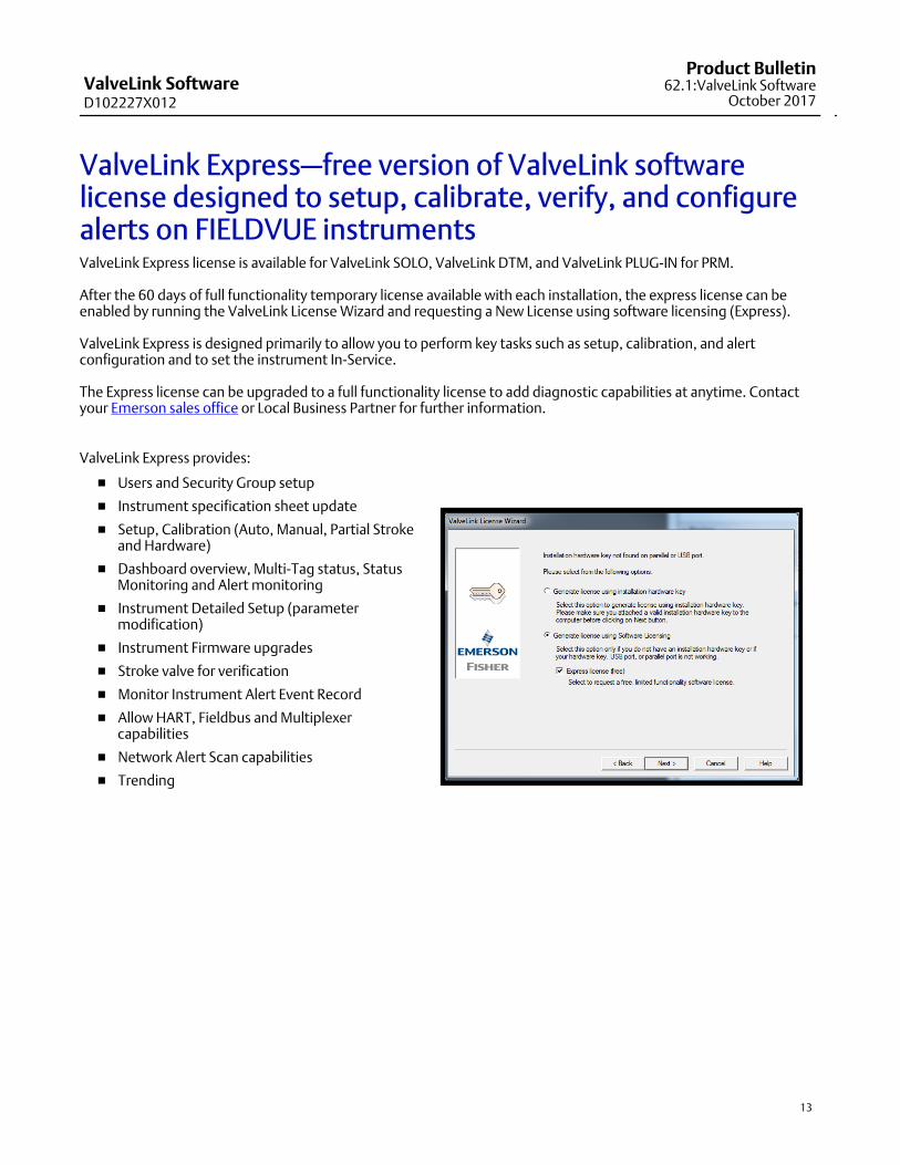
ValveLink Express—free version of ValveLink softwarelicense designed to setup, calibrate, verify, and configurealerts on FIELDVUE instrumentsValveLink Express license is available for ValveLink SOLO, ValveLink DTM, and ValveLink PLUG-IN for PRM.
After the 60 days of full functionality temporary license available with each installation, the express license can beenabled by running the ValveLink License Wizard and requesting a New License using software licensing (Express).
ValveLink Express is designed primarily to allow you to perform key tasks such as setup, calibration, and alertconfiguration and to set the instrument In-Service.
The Express license can be upgraded to a full functionality license to add diagnostic capabilities at anytime. Contactyour Emerson sales office or Local Business Partner for further information.
ValveLink Express provides:
� Users and Security Group setup
� Instrument specification sheet update
� Setup, Calibration (Auto, Manual, Partial Stroke and Hardware)
� Dashboard overview, Multi-Tag status, Status Monitoring and Alert monitoring
� Instrument Detailed Setup (parameter modification)
� Instrument Firmware upgrades
� Stroke valve for verification
� Monitor Instrument Alert Event Record
� Allow HART, Fieldbus and Multiplexer capabilities
� Network Alert Scan capabilities
� Trending
ValveLink SoftwareD102227X012
Product Bulletin62.1:ValveLink SoftwareOctober 2017
14
Specifications
Hardware Requirements
Computer and processor:
1 gigahertz (GHz) processor
Memory:
512 megabytes (MB) RAM (Windows XP)
1 gigabyte (GB) RAM (All other Operating Systems)
Hard disk:
No Trending - 65 MB available storage space
Trending - 125 MB available storage space
Drive:
CD-ROM Drive
Display:
1024 X 768 resolution
I/O (ValveLink Solo):
USB Port required for instrument level step-ups
HART communications require at least one of thefollowing interfaces:
HART Modem - Standard RS-232 Port��(requires dedicated interrupt)
HART Multiplexer - Standard RS-232 Port��(requires RS-485 converter)
MACTek VIATOR USB HART Modem - USB Port
MACTek VIATOR Bluetooth HART Interface -��Windows Bluetooth Serial Port Profile (SPP)
Modbus communications require the following:
Standard RS-232 Port
Additional HART Interface (see above)
FOUNDATION Fieldbus communications require at��least one of the following:
National Instruments Fieldbus H1 interfaces
NI USB-8486
PCI-FBUS/2 and above
PCMCIA-FBUS/2 Series 2 and above
Emerson USB Fieldbus Interface (v3.0)
NI-FBUS Configuration - 2 Port Card
The following settings are applicable forconfiguration of a NI-FBUS 2 Port Card: a) If only one port will be connected to a LIVE���segment, the other port must be set to “LAS”���(not “Bus Monitor”)
b) If both ports will be connected to LIVE segments,���then both ports must be set to “Basic” mode.
NI driver software must be installed BEFORE installingthe NI hardware.
Other configurations may result in initializationfailure of the NI Communication Manager software
Supported Languages
ValveLink Software v13.3 is only available in English
Supported Operating Systems
ValveLink SoloWindows Server 2003 SP2 (32bit)Windows� XP SP3 (32 bit)Windows 7 Professional SP1 (32 and 64 bit)Windows 7 Enterprise SP1 (32 and 64 bit)Windows Server� 2008 SP2 (64 bit)Windows Server 2008 R2 SP1 (64 bit)Windows 8 Professional (64 bit)Windows 8 Enterprise (64 bit)Windows 8.1 Professional (64 bit)Windows 8.1 Enterprise (64 bit)Windows Server 2012 Essential (64 bit)Windows Server 2012 Datacenter (64 bit)Windows Server 2012 R2 Essential (64 bit)Windows Server 2012 R2 Datacenter (64 bit)Windows 10 Professional (64 bit)Windows 10 Enterprise (64 bit)Windows Server 2016 Standard (64 bit)Windows Server 2016 Datacenter (64 bit)
ValveLink SNAP-ON for AMS Device ManagerOperating systems supported by AMS DeviceManager v11.0, v11.1.1, v11.5, v12.0, v12.5, v13.0,�v13.1.1, v13.5
ValveLink PLUG-IN for PRMOperating systems supported by Yokogawa Plant�Resource Manager (PRM) v3.12 or newer.
Software Requirements
Internet Explorer 6.0 or later Microsoft Windows Installer 3.1 or later �(3.5 recommended; required by �Microsoft .NET Framework)
ValveLink SoftwareD102227X012
Product Bulletin62.1:ValveLink Software
October 2017
15
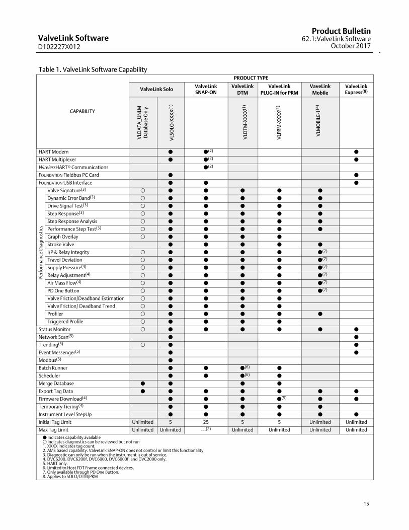
Table 1. ValveLink Software Capability
CAPABILITY
PRODUCT TYPE
ValveLink SoloValveLinkSNAP‐ON
ValveLink
DTM
ValveLink
PLUG‐IN for PRM
VaveLink
Mobile
ValveLinkExpress(8)
VLD
AT
A_
UN
LM
Dat
abas
e O
nly
VLS
OLO
-XX
XX
(1)
VLD
TM
-XX
XX
(1)
VLP
RM
-XX
XX
(1)
VLM
OB
ILE-
1(4
)
HART Modem � �(2) �
HART Multiplexer � �(2) �
WirelessHART� Communications �(2)
FOUNDATION Fieldbus PC Card � �
FOUNDATION USB Interface � � �
Pe
rfo
rman
ce D
iag
no
stic
s
Valve Signature(3) � � � � � �
Dynamic Error Band(3) � � � � � �
Drive Signal Test(3) � � � � � �
Step Response(3) � � � � � �
Step Response Analysis � � � � � �
Performance Step Test(3) � � � � � �
Graph Overlay � � � � �
Stroke Valve � � � � �
I/P & Relay Integrity � � � � � �(7)
Travel Deviation � � � � � �(7)
Supply Pressure(4) � � � � � �(7)
Relay Adjustment(4) � � � � � �(7)
Air Mass Flow(4) � � � � � �(7)
PD One Button � � � � � �(7)
Valve Friction/Deadband Estimation � � � � �
Valve Friction/ Deadband Trend � � � � �
Profiler � � � � � �
Triggered Profile � � � � �
Status Monitor � � � � � � �
Network Scan(5) � �
Trending(5) � � �
Event Messenger(5) � �
Modbus(5) �
Batch Runner � � �(6) �
Scheduler � � �(6) �
Merge Database � � � �
Export Tag Data � � � � � � �
Firmware Download(4) � � � �(5) � �
Temporary Tiering(4) � � � � �
Instrument Level StepUp � � � � � �
Initial Tag Limit Unlimited 5 25 5 5 Unlimited Unlimited
Max Tag Limit Unlimited Unlimited ---(2) Unlimited Unlimited Unlimited Unlimited
� Indicates capability available� Indicates diagnostics can be reviewed but not run1. XXXX indicates tag count.2. AMS based capability. ValveLink SNAP‐ON does not control or limit this functionality.3. Diagnostic can only be run when the instrument is out of service.4. DVC6200, DVC6200f, DVC6000, DVC6000f, and DVC2000 only.5. HART only.6. Limited to Host FDT Frame connected devices.7. Only available through PD One Button.8. Applies to SOLO/DTM/PRM

ValveLink SoftwareD102227X012
Product Bulletin62.1:ValveLink SoftwareOctober 2017
16
Emerson Automation SolutionsMarshalltown, Iowa 50158 USASorocaba, 18087 BrazilCernay, France 68700Dubai, United Arab EmiratesSingapore 128461 Singapore
www.Fisher.com
The contents of this publication are presented for informational purposes only, and while every effort has been made to ensure their accuracy, they are notto be construed as warranties or guarantees, express or implied, regarding the products or services described herein or their use or applicability. All sales aregoverned by our terms and conditions, which are available upon request. We reserve the right to modify or improve the designs or specifications of suchproducts at any time without notice.
� 1995, 2017 Fisher Controls International LLC. All rights reserved.
Fisher, FIELDVUE, ValveLink, SNAP-ON, DeltaV, Ovation, and PROVOX are marks owned by one of the companies in the Emerson Automation Solutionsbusiness unit of Emerson Electric Co. Emerson Automation Solutions , Emerson, and the Emerson logo are trademarks and service marks of Emerson ElectricCo. HART and WirelessHART are registered trademarks of FieldComm Group. FOUNDATION Fieldbus is a trademark of FieldComm Group. Microsoft, Windows,Windows Server, and Windows Vista are registered trademarks of Microsoft Corporation in the United States and other countries. All other marks are theproperty of their respective owners.
Neither Emerson, Emerson Automation Solutions, nor any of their affiliated entities assumes responsibility for the selection, use or maintenanceof any product. Responsibility for proper selection, use, and maintenance of any product remains solely with the purchaser and end user.