
Product Airstream™ Data Hydronic Ceiling Cassettes
16
© Carrier Corporation 2014 Form 42WKN-5PD Hydronic ceiling cassette units offer: • 6 chilled water cooling models to properly match job • Optional electric heat or hot water coil • Wall-mounted thermostat • Installation cost savings through use of exisiting piping and/or wiring • Low noise level construction • Optional microprocessor based controller with infrared transmitter Features/Benefits Ceiling cassette units make each served area an independent controlled temperature zone to suit diverse requirements. Construction Cases are constructed of lightweight galvanized sheet steel with integral fan mounting rails for added strength. Fire resistant foam insulation (rated to UL94 VO) is fitted internally to provide both thermal and acoustic insulation. The pearl-gray fascia is constructed of high-impact polystyrene. Chilled water coil Units use large surface area coils posi- tioned to optimize heat transfer and airflow. Each coil is manufactured from copper tubes with mechanically bond- ed aluminum fins and is circuited from headers to ensure low water pressure drops. Airstream™ 42WKN08-36 Hydronic Ceiling Cassettes 50/60 Hz 3 / 4 to 3 Nominal Tons (2.6 to 10.6 kW) Product Data UNIT SIZES 08-12 UNIT SIZES 18-36 a42-4013 a42-4014
Transcript of Product Airstream™ Data Hydronic Ceiling Cassettes

© Carrier Corporation 2014 Form 42WKN-5PD
Hydronic ceiling cassette units offer:• 6 chilled water cooling models to
properly match job• Optional electric heat or hot water
coil• Wall-mounted thermostat• Installation cost savings through
use of exisiting piping and/or wiring• Low noise level construction• Optional microprocessor based
controller with infrared transmitter
Features/BenefitsCeiling cassette units make each served area an independent controlled temperature zone to suit diverse requirements. ConstructionCases are constructed of lightweight galvanized sheet steel with integral fan mounting rails for added strength. Fire resistant foam insulation (rated to UL94 VO) is fitted internally to provide both thermal and acoustic insulation.
The pearl-gray fascia is constructed of high-impact polystyrene.
Chilled water coilUnits use large surface area coils posi-tioned to optimize heat transfer and airflow. Each coil is manufactured from copper tubes with mechanically bond-ed aluminum fins and is circuited from headers to ensure low water pressure drops.
Airstream™42WKN08-36
Hydronic Ceiling Cassettes50/60 Hz
3/4 to 3 Nominal Tons(2.6 to 10.6 kW)
ProductData
UNIT SIZES 08-12
UNIT SIZES 18-36
a42-4013
a42-4014

2
FanThe backward-curved, centrifugal fans are statically and dynamically balanced for quiet operation. Fan impellers are made from either aluminum or fire-retardant plastic (UL94 VO) for lightweight and corrosion-resistant operation. En-closed multi-speed external rotor fan motor allows good heat dissipation and increased motor efficiency. Fans come complete with thermal over-load protection and sealed-for-life lubricated bearings.
FiltrationReusable wire framed filters are fitted and may be vacuum cleaned.
Condensate pumpA condensate pump is fitted to carry water out of the unit. The pump is fixed to a mounting bracket which can be withdrawn from the side of the chassis and incorporates an in-spection hole to allow a visual check of the pump during operation. A float switch is fitted to stop the cool-ing action should the pump become blocked or fail.
Air vanesAir outlet vanes are manufactured from aluminum and covered with ny-lon flock to prevent condensation from forming. Vanes are manually adjustable on unit sizes 08,12 and
driven by an electric motor on unit sizes 18-36. Motorized air vanes can be set to auto sweep or can be stopped in a fixed position. Polysty-rene blanking pieces are supplied with cassette packing so that up to two fascia discharge slots can be blanked off.
Alarm interlock relayAlarm interlock relay includes a relay for unit failure notification. Normally open/normally closed contacts are available for field connection.
Table of contentsPage
Features/Benefits. . . . . . . . . . . . . . . . . . . . . . . . . . . . . . . . . . . . . . . . . .1,2Model Number Nomenclature . . . . . . . . . . . . . . . . . . . . . . . . . . . . . . . . . . 2Physical Data . . . . . . . . . . . . . . . . . . . . . . . . . . . . . . . . . . . . . . . . . . . . . . 3Options and Accessories . . . . . . . . . . . . . . . . . . . . . . . . . . . . . . . . . . . . .4,5Dimensions . . . . . . . . . . . . . . . . . . . . . . . . . . . . . . . . . . . . . . . . . . . . . .6-8Selection Procedure . . . . . . . . . . . . . . . . . . . . . . . . . . . . . . . . . . . . . . . . . 9Performance Data . . . . . . . . . . . . . . . . . . . . . . . . . . . . . . . . . . . . . . .10,11Electrical Data . . . . . . . . . . . . . . . . . . . . . . . . . . . . . . . . . . . . . . . . . . . . 12Typical Wiring Schematic . . . . . . . . . . . . . . . . . . . . . . . . . . . . . . . . . . . . 12Controls . . . . . . . . . . . . . . . . . . . . . . . . . . . . . . . . . . . . . . . . . . . . . . . . 13Guide Specifications . . . . . . . . . . . . . . . . . . . . . . . . . . . . . . . . . . . . . .14,15
Features/Benefits (cont)
Model number nomenclature42 SERIES HYDRONIC CEILING CASSETTES
20 N
42WKN – Hydronic Cooling Ceiling Cassette
Supply VoltageA – 115-1-60B – 208-1-60C – 230-1-60H – 277-1-60J – 110-1-50K – 220-1-50
A
Design RevisionA – Current Design
ControlE – Electro-Mechanical ControlsM – Microprocessor Controls
Heating OptionN – NoneA – Electric HeatB – Hot Water Heating Coil
FiltrationA – Cleanable FilterB – MERV 8 Filter
A E42WKN
Unit Size and Nominal Capacity08 – 8 MBtuh12 – 12 MBtuh18 – 18 MBtuh20 – 20 MBtuh33 – 33 MBtuh36 – 36 MBtuh
A

3
LEGEND NOTES:1. Cooling capacity based on 80 F dry bulb/67 F wet bulb indoor and
a 45 F entering/55 F leaving chilled water temperature.2. Heating capacity based on water temperature of 180 F inlet /160 F
outlet and an air temperature of 70 F dry bulb.3. Ducted air volume based on maximum air volume available
through one branch duct 6 ft long, with cassette fan(s) at highspeed and corresponding fascia aperture closed.
4. Fresh air volume based on maximum fresh air through all knock-outs connected to one 10 ft long duct with fan at high speed.
42WKN UNIT SIZE 08 12 18 20 33 36NOMINAL TONS 3/4 1 11/2 13/4 21/2 3COOLING CAPACITY (Btuh) 6,601 11,091 17,592 19,087 29,722 35,258DIMENSIONS/WEIGHTS
Height – Chassis/Fascia (in.)(not additive) 113/4 / 11/4 113/4 / 11/4 11 / 13/4 11 / 13/4 13 / 13/4 13 / 13/4
Width – Chassis/Fascia (in.) 221/2 / 25 221/2 / 25 323/8 / 37 323/8 / 37 451/2 / 491/4 451/2 / 491/4Depth – Chassis/Fascia (in.) 221/2 / 25 221/2 / 25 323/8 / 37 323/8 / 37 323/8 / 37 323/8 / 37Weight – Chassis/Fascia (lb) 40 / 5 40 / 5 64 / 18 64 / 18 97 / 21 97 / 21
CHILLED WATER COILType Finned TubeQuantity 1 1 1 1 1 1Face Area (sq ft) 1.8 1.8 2.8 2.8 5.2 5.2Nominal Airflow (cfm)High 350 350 630 700 970 1160Medium 300 300 530 630 890 970Low 260 260 500 530 785 890
Discharge 4-way 4-way 4-way 4-way 4-way 4-wayUnit Water Volume (gal) 0.29 0.29 0.45 0.45 0.79 0.79
FANType CentrifugalQuantity 1 1 1 1 2 2Diameter (in.) 12 12 15 15 14 14Horsepower per fan (Hp) 1/8 1/8 1/8 1/8 1/8 1/8
CONNECTIONS (Sweat)Chilled Water Inlet, OD (in.) 5/8 5/8 7/8 7/8 7/8 7/8Chilled Water Outlet, OD (in.) 5/8 5/8 7/8 7/8 7/8 7/8Condensate, ID (in.) 3/8 3/8 3/8 3/8 3/8 3/8
FILTRATIONType Cleanable Wire FramedQuantity 1 1 2 2 3 3Arrestance 80% 80% 80% 80% 80% 80%Type MERV 8 ThrowawayQuantity 1 1 2 2 3 3Size (in.) 12x12x1 12x12x1 12x24x1 12x24x1 12x24x1 12x24x1
CONDENSATE PUMPMaximum Head (in.) 30 30 30 30 30 30Nominal Flow Rate (gpm) 0.1 0.1 0.1 0.1 0.1 0.1
HEATING OPTIONElectric Heating Capacity (kW) 1.5 1.5 3.0 3.0 5.0 5.0Hot Water Heating Capacity (Btuh) 13,799 N/A 29,258 30,946 46,455 51,600Hot Water Coil Connection, OD (in.) (Sweat) 5/8 N/A 5/8 5/8 5/8 5/8
BRANCH DUCT OPTIONBranch Duct Connections (quantity) 2 2 2 2 2 2Branch Duct Diameter (in.) 5 5 5 5 6 6Ducted Air Volume (cfm) 80 80 100 125 200 220
FRESH AIR OPTIONFresh Air Connections (quantity) 1-2 1-2 1-3 1-3 1-3 1-3Fresh Air Duct Diameter (in.) 3 3 3 3 3 3Fresh Air Volume (cfm) 40 40 60 65 90 95
ID — Inside DiameterN/A — Not ApplicableOD — Outside Diameter
Physical data
4
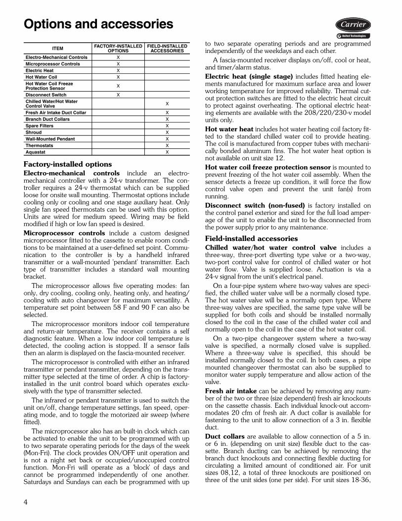
Factory-installed optionsElectro-mechanical controls include an electro-mechanical controller with a 24-v transformer. The con-troller requires a 24-v thermostat which can be suppliedloose for onsite wall mounting. Thermostat options includecooling only or cooling and one stage auxiliary heat. Onlysingle fan speed thermostats can be used with this option.Units are wired for medium speed. Wiring may be fieldmodified if high or low fan speed is desired.Microprocessor controls include a custom designedmicroprocessor fitted to the cassette to enable room condi-tions to be maintained at a user-defined set point. Commu-nication to the controller is by a handheld infraredtransmitter or a wall-mounted 'pendant' transmitter. Eachtype of transmitter includes a standard wall mountingbracket.
The microprocessor allows five operating modes: fanonly, dry cooling, cooling only, heating only, and heating/cooling with auto changeover for maximum versatility. Atemperature set point between 58 F and 90 F can also beselected.
The microprocessor monitors indoor coil temperatureand return-air temperature. The receiver contains a selfdiagnostic feature. When a low indoor coil temperature isdetected, the cooling action is stopped. If a sensor failsthen an alarm is displayed on the fascia-mounted receiver.
The microprocessor is controlled with either an infraredtransmitter or pendant transmitter, depending on the trans-mitter type selected at the time of order. A chip is factory-installed in the unit control board which operates exclu-sively with the type of transmitter selected.
The infrared or pendant transmitter is used to switch theunit on/off, change temperature settings, fan speed, oper-ating mode, and to toggle the motorized air sweep (wherefitted).
The microprocessor also has an built-in clock which canbe activated to enable the unit to be programmed with upto two separate operating periods for the days of the week(Mon-Fri). The clock provides ON/OFF unit operation andis not a night set back or occupied/unoccupied controlfunction. Mon-Fri will operate as a 'block' of days andcannot be programmed independently of one another.Saturdays and Sundays can each be programmed with up
to two separate operating periods and are programmedindependently of the weekdays and each other.
A fascia-mounted receiver displays on/off, cool or heat,and timer/alarm status.Electric heat (single stage) includes fitted heating ele-ments manufactured for maximum surface area and lowerworking temperature for improved reliability. Thermal cut-out protection switches are fitted to the electric heat circuitto protect against overheating. The optional electric heat-ing elements are available with the 208/220/230-v modelunits only. Hot water heat includes hot water heating coil factory fit-ted to the standard chilled water coil to provide heating.The coil is manufactured from copper tubes with mechani-cally bonded aluminum fins. The hot water heat option isnot available on unit size 12.Hot water coil freeze protection sensor is mounted toprevent freezing of the hot water coil assembly. When thesensor detects a freeze up condition, it will force the flowcontrol valve open and prevent the unit fan(s) fromrunning.Disconnect switch (non-fused) is factory installed onthe control panel exterior and sized for the full load amper-age of the unit to enable the unit to be disconnected fromthe power supply prior to any maintenance.
Field-installed accessoriesChilled water/hot water control valve includes athree-way, three-port diverting type valve or a two-way,two-port control valve for control of chilled water or hotwater flow. Valve is supplied loose. Actuation is via a24-v signal from the unit's electrical panel.
On a four-pipe system where two-way valves are speci-fied, the chilled water valve will be a normally closed type.The hot water valve will be a normally open type. Wherethree-way valves are specified, the same type valve will besupplied for both coils and should be installed normallyclosed to the coil in the case of the chilled water coil andnormally open to the coil in the case of the hot water coil.
On a two-pipe changeover system where a two-wayvalve is specified, a normally closed valve is supplied.Where a three-way valve is specified, this should beinstalled normally closed to the coil. In both cases, a pipemounted changeover thermostat can also be supplied tomonitor water supply temperature and allow action of thevalve.Fresh air intake can be achieved by removing any num-ber of the two or three (size dependent) fresh air knockoutson the cassette chassis. Each individual knock-out accom-modates 20 cfm of fresh air. A duct collar is available forfastening to the unit to allow connection of a 3 in. flexibleduct.Duct collars are available to allow connection of a 5 in.or 6 in. (depending on unit size) flexible duct to the cas-sette. Branch ducting can be achieved by removing thebranch duct knockouts and connecting flexible ducting forcirculating a limited amount of conditioned air. For unitsizes 08,12, a total of three knockouts are positioned onthree of the unit sides (one per side). For unit sizes 18-36,
ITEM FACTORY-INSTALLED OPTIONS
FIELD-INSTALLED ACCESSORIES
Electro-Mechanical Controls XMicroprocessor Controls XElectric Heat XHot Water Coil XHot Water Coil Freeze Protection Sensor X
Disconnect Switch XChilled Water/Hot Water Control Valve X
Fresh Air Intake Duct Collar XBranch Duct Collars XSpare Filters XShroud XWall-Mounted Pendant XThermostats XAquastat X
Options and accessories

5
a total of four knockouts are available and are arranged inpairs along two of the unit sides (two per side).NOTE: On the 08,12 size units, it is recommended thatonly one of the three branch duct knockouts is utilized, dueto the small capacity of the unit.Spare filters accessories include either a cleanable wiremesh filter or a throwaway MERV 8 filter.Shroud is a sheet metal cover used to cover unit housingwhen the unit is not mounted in a drop or false ceiling. Theshroud is painted Sky White with a hammertone finish.
Wall-mounted pendant for communication to themicroprocessor controller replaces the standard infraredremote control. This accessory requires the wall-mountedpendant base be wired back to the unit. When this acces-sory is ordered, the unit will not ship with the infraredremote.Thermostats are available for use with the electrome-chanical controller. These thermostats operate with 24-vpower and are for wall mounting. Several options are avail-able depending upon system type. Aquastat is available for use with a 2-pipe heating/cooling changeover system.

6
Dimensions
25 3/16
25 3/16
1 11/16
22 1/211 1/4
2 3/4
10 11/16
19 9/16
19 1/2 12 9/16
1 7/16
22 15/16
7/8
22 1/2
8 13/16
11 5/16
4 11/16
3 11/16
2 5/8
O 5 3/16
6 1/25 1/83 3/4 2 1/16
2 5/8
A
A
VIEW A-A
9 13/16
1 1/8
2 3/4
5
78
9
5
10
6
1. CW Inlet2. CW Outlet3. HW Coil Inlet (Optional)4. HW Coil Outlet (Optional)5. Branch Duct Opening (x3)6. Fresh Air Intake (x2)7. Pump Inspection Port8. Condensate Drain9. Control Panel10. Mounting Bracket
1 2
3
4
3 3/8
3 5/8
42WKN08 AND 42WKN12 UNIT
NOTE: Dimensions shown in inches.
a42-4319.eps

7
37
37
11/16
32 3/8
2 3/4
9 1/2
2 5/8
28 11/16
31 3/8
28 9/16 12 9/16
1 13/16
4 5/86
8 5/8
1 5/8
5 5/167 3/4
2 3/4 2 3/44 7/8
4 15/16
32 5/165 3/8
3 3/16
1 5/163
8 13/16
8 11/16
11 13/16
3 1/87 13/16
2 3/4
VIEW A-A
A
A
2
5
1
4
10
5
6
7
8
9
3
5 3/8
1. CW Coil Inlet2. CW Coil Outlet3. HW Coil Inlet (Optional)4. HW Coil Outlet (Optional)5. Fresh Air Intake (x3)6. Branch Duct Opening (x4)7. Pump Inspection Port8. Condensate Drain9. Control Panel10. Mounting Bracket
42WKN18 AND 42WKN20 UNIT
NOTE: Dimensions shown in inches.
a42-4319

8
Dimensions (cont)
A
A
VIEW A-A
49 3/16
37
2 1/4
32 3/8
4 3/4
11 1/2
2 5/8
28 11/16
12 9/1628 9/16 1 7/8
43 1/2
7/8 8 13/16
19 5/8
12 7/16
6 3/8
3 5/8
3 3/8
3
64 5/8
7 3/16
2 3/16
4 3/47 9/16
9 13/16
1 5/8
4 7/82 3/42 3/4
3 1/89 13/162 3/4
5
10
2
5
4
31
6
7
9
8
1. CW Coil Inlet2. CW Coil Outlet3. HW Coil Inlet (Optional)4. HW Coil Outlet (Optional)5. Fresh Air Intake (x3)6. Branch Duct Opening (x4)7. Pump Inspection Port8. Condensate Drain9. Control Panel10. Mounting Bracket
42WKN33 AND 42WKN36 UNIT
NOTE: Dimensions shown in inches.
a42-4329

9
I Determine job requirements.
Given:Room Sensible Cooling Load . . . . . . . .8,200 BtuhRoom Total Cooling Load . . . . . . . . .11,000 BtuhEntering-Air Temperature . . . . . . 80 F at 50% RHEntering Water Temperature . . . . . . . . . . . . .45 FTemperature Rise . . . . . . . . . . . . . . . . . . . . .10 FNominal Air Delivery . . . . . . . . . . . . . . . . 350 cfm
II Determine unit size and nominal cfm.For an initial selection, choose a unit size that willprovide the required airflow (cfm). Refer to thePhysical Data table on page 3. At high speed, a42WKN12 unit will provide 350 cfm.
III Determine total cooling capacity.Refer to the cooling capacity table for 42WKN12on page 10. Locate required entering dry bulb (edb)and relative humidity (RH) conditions. Locate theentering water temperature required. Under TotalCooling (TC) column, a 42WKN12 unit at an enter-ing-air temperature of 80 F dry bulb at 50% RH, anentering water temperature of 45 F, and a watertemperature rise of 10 F, will provide 11,236 Btuh.
IV Determine sensible cooling capacity.In cooling capacity table for 42WKN12, locate thesensible cooling (SC) column and find that the42WKN12 at the required conditions will provide8,200 Btuh of sensible cooling at a water tempera-ture rise of 10 F. The 42WKN12 will satisfy the jobrequirements.If additional SC were required, a larger unit or alower entering water temperature would be needed.
Selection procedure (42WKN12 unit example)

10
CHILLED WATER UNIT COOLING CAPACITIES
LEGEND NOTES:1. All duties based on high fan speed except where stated otherwise.2. Cooling capacities are gross. Do not include fan motor gains.3. Pressure drops are coil only (excludes valves).4. Hot water duties on chilled water units fitted with additional,
optional hot water coil. See data on next page.
HOT WATER COIL HEATING CAPACITIES
LEGEND
NOTES:1. All duties based on high fan speed except where stated otherwise.2. Pressure drops are coil only, excluding valves.3. Hot water duties based on units fitted with additional, optional hot water coil.4. Hot water coil not available on size 42WKN12.
42WKN UNIT SIZE
ENTERINGDB AIR
TEMPERATURE (F) at 50% RH
CHILLED WATER ENTERING/LEAVING TEMPERATURE40/50 F 45/55 F
TC (Btuh) SC (Btuh) Flow (gpm)
Pressure Drop (psi) TC (Btuh) SC (Btuh) Flow
(gpm)Pressure Drop (psi)
0872 5,236 5,156 1.1 2.4 3,999 3,999 0.8 1.575 6,528 5,989 1.3 3.5 4,729 4,729 1.0 2.080 10,037 7,529 2.0 7.6 7,026 6,107 1.4 4.0
1272 8,723 7,261 1.8 1.9 5,623 5,623 1.1 0.975 10,831 8,173 2.2 2.7 7,502 6,604 1.5 1.480 14,435 9,644 2.9 4.6 11,236 8,200 2.3 2.9
1872 13,728 12,126 2.8 1.9 9,295 9,295 1.9 0.975 17,478 13,840 3.5 2.8 11,447 10,853 2.3 1.480 24,588 16,659 4.9 5.1 18,432 13,900 3.7 3.1
2072 14,810 13,098 3.0 2.1 10,103 10,103 2.0 1.175 18,956 14,985 3.8 3.3 12,341 11,716 2.5 1.580 26,569 18,022 5.3 5.9 19,971 15,041 4.0 3.6
3372 23,570 20,321 4.7 3.5 15,695 15,695 3.2 1.775 29,100 22,928 5.8 5.1 19,912 18,365 4.0 2.780 41,598 28,029 8.3 9.6 30,595 23,129 6.1 5.6
3672 27,054 23,385 5.4 4.5 18,066 18,066 3.6 2.275 33,895 26,690 6.8 6.7 22,721 21,074 4.6 3.380 47,991 32,334 9.6 12.5 35,934 26,916 7.2 7.5
DB — Dry BulbRH — Relative HumiditySC — Sensible Cooling CapacityTC — Total Cooling Capacity
42WKN UNIT SIZE ENTERING DB AIR TEMPERATURE (F) at 50% RH
HOT WATER INLET 180F/160FHeating Capacity (Btuh) Flow Rate (gpm) Pressure Drop (psi)
0850 16,819 1.8 3.960 15,292 1.6 3.370 13,799 1.4 2.7
1250 N/A N/A N/A60 N/A N/A N/A70 N/A N/A N/A
1850 35,763 3.7 3.460 32,480 3.4 2.970 29,258 3.1 2.4
2050 37,938 4.0 3.760 34,401 3.6 3.270 30,946 3.2 2.7
3350 55,683 5.8 4.060 51,120 5.3 3.570 46,555 4.9 3.0
3650 62,005 6.5 4.860 56,762 5.9 4.170 51,600 5.4 3.5
DB — Dry BulbN/A — Not ApplicableRH — Relative Humidity
Performance data

11
CHILLED WATER UNIT — TWO-PIPE CHANGEOVER HEATING CAPACITIES
LEGEND
NOTES:1. All duties based on high fan speed except where stated otherwise.2. Pressure drops are coil only, excluding valves.
SOUND DATA
LEGEND
NOTE: Overall SPL measured at a distance of 5 ft below the fascia infree field, dry coil conditions, referenced to 2 x 10⁵Pa.
42WKN UNIT SIZE ENTERING DB AIR TEMPERATURE (F) at 50% RH
HOT WATER INLET 180F/160FHeating Capacity (Btuh) Flow Rate (gpm) Pressure Drop (psi)
0850 28,389 3.0 11.060 25,903 2.7 9.470 23,605 2.5 8.0
1250 33,471 3.5 4.660 30,715 3.2 4.070 27,995 2.9 3.4
1850 60,388 6.3 5.760 55,127 5.8 4.870 49,706 5.2 4.0
2050 65,350 6.8 6.560 59,887 6.3 5.670 54,118 5.7 4.7
3350 99,476 10.4 10.160 91,494 9.6 8.870 82,986 8.7 7.4
3650 114,225 11.9 13.060 105,132 11.0 11.270 95,896 10.0 9.5
DB — Dry BulbRH — Relative Humidity
42WKN UNIT SIZE FAN SPEED SPL
dBASOUND PRESSURE FREQUENCY SPECTRUM, dB
125 Hz 250 Hz 500 Hz 1000 Hz 2000 Hz 4000 Hz 8000 Hz
08High 29 37 37 33 29 21 14 10Med 26 34 34 30 24 15 12 10Low 22 31 29 25 17 8 10 8
12High 35 42 41 38 35 28 21 12Med 32 38 39 36 32 24 16 10Low 29 37 37 33 29 21 14 10
18High 43 41 45 38 40 33 25 17Med 39 39 41 35 36 27 19 16Low 38 38 40 34 34 25 18 16
20High 46 43 47 40 43 37 29 19Med 43 41 45 38 40 33 25 17Low 39 39 41 35 36 27 19 16
33High 48 51 49 46 42 34 22 19Med 44 50 46 43 38 28 18 17Low 42 49 44 41 36 25 17 16
36High 52 54 54 50 46 41 27 24Med 48 51 49 46 42 34 22 19Low 45 50 47 44 39 31 19 18
SPL — Sound Pressure Level

12
LEGEND
*Standard unit fitted with optional electric heating elements. Availablewith 208/220/230-v model units only.
Typical wiring schematicNOTE: Refer to Installation and Operation manual forwiring schematic.
42WKN NOMINAL CAPACITY
(Digit 4,5)
SUPPLY VOLTAGE (Digit 6)
PERFORMANCE (WITH ELECTRIC HEAT)* PERFORMANCE (NO ELECTRIC HEAT)
FLA MCA Recommended Fuse Size FLA MCA Recommended
Fuse Size
08 and 12Small Chassis
A: 115-60-1— — — 0.70 0.88 15
J: 110-50-1
B: 208-60-1 6.25 7.81 15
0.35 0.44 15C: 230-60-1 6.87 8.59 15
K: 220-50-1 6.59 8.24 15
H: 277-60-1 — — — 0.29 0.36 15
18 and 20Medium Chassis
A: 115-60-1— — — 1.10 1.38 15
J: 110-50-1
B: 208-60-1 12.35 15.44 20
0.55 0.69 15C: 230-60-1 13.59 16.99 20
K: 220-50-1 13.03 16.29 20
H: 277-60-1 — — — 0.46 0.58 15
33 and 36Large Chassis
A: 115-60-1— -— -— 1.92 2.40 15
J: 110-50-1
B: 208-60-1 20.68 25.85 30
0.96 1.20 15C: 230-60-1 22.76 28.45 30
K: 220-50-1 21.81 27.26 30
H: 277-60-1 — — — 0.80 1.00 15
FLA — Full Load AmpsMCA — Minimum Circuit Amps
Electrical data
13
Sequence of operation
Electro-mechanical controls — A 24-v signal from thethermostat to terminal G supplies power to the blowermotor(s), condensate pump and vane motor (if equipped).A toggle switch on the control box can be used to switchthe oscillating vanes on or off. The condensate pump willrun continuously, as long as the blower is energized. A callfor heating, at terminal W, or cooling, at terminal Y, willenergize the water valve actuator and allow water to flowthrough the cassette coil. When the call for heating or cool-ing is satisfied the valve will close.
If the temperature drops below the set point of the coilfreezestat, the water valve with automatically open to circu-late water through the coil.
If the condensate float switch detects a high level ofwater in the condensate tray, the switch will open, activatethe condensate pump and disable the heating/cooling sig-nal until the water level drops down to normal.Microprocessor controls — The PCB (printed circuitboard) microprocessor control board relays control theoperation of the indoor-fan motor, outdoor-fan motor,compressor and electric heater (if fitted), to maintain roomconditions at a user-defined set point.
Temperature settings, fan speeds and other controlfunctions can be changed by the infrared transmitter oroptional pendant. The controller PCB provides the follow-ing input/output facilities:InputsT1 Return Air Temperature Sensor: 50k at 77 F.T3 Indoor Coil Temperature Sensor: 50k at 77 F.OutputsIndoor fan motor — The controller will switch a combina-tion of three, 10-amp, 230-vac (3 speed settings) resistiverated relays to deliver the selected indoor fan speed.Condensate pump — Activated when unit is in coolingmode.Vane motor — A 10-amp, 230-vac resistive rated relayswitches the vane motor on when Air Sweep is selected(units sizes 18-36 only).Electric heat — A 30-amp, 230-vac resistive rated relayswitches the electric heater on when required.
Indoor fan operationThe indoor fan will run continuously at the most recentlyset speed or will alter the speed according to the roomtemperature conditions when set to Auto. The indoor fanwill continue to run until the unit is turned off by the user orby a preset time setting. When the unit is turned off duringheating, the indoor fan will continue to run for approxi-mately 2 minutes, this helps to dissipate residual heat fromthe electric heaters.
Boost heatThe electric heat relay can be used to initiate either lowwatts density electric heating (optional) or low pressure hotwater heating (optional). The boost heat will be activatedwhen the room temperature falls to more than 8º F belowset point. Hysteresis of 2º F will be applied to prevent
“hunting.” The boost heat facility is automatically enabledor disabled by selecting non heat pump (Jumper 2 open).
Temperature controlThe controller will switch heating or cooling loads in orderto maintain the temperature set point. The deadband isprogrammed to 4º F. Under normal operation, cooling orheating will be activated at the limits of the deadband andwill continue to operate until set point is achieved.
The temperature set point can be adjusted between58 and 90 F in 2º F increments.
Power failureThe controller will auto restart in its previous mode ofoperation after a power failure. When power is restored,the controller will revert to its last operating mode, e.g., ifthe controller was turned on before power fail, after poweris restored the controller will automatically turn on. Alter-natively, if the controller was turned off before power fail,the controller will remain off after power is restored.
Electric heater overheat protectionIn the event of an auto reset overheat cutout, the electricheater will be switched off until the temperature drops suf-ficiently for the auto cutout to reset itself.
Master/slave operationThe network option allows for one master unit and up to19 slave units to be interconnected using a twin twistedpair screened cable to create a network.
The master/slave operation has been programmed tooperate the units in the following manner:
When the master unit receives a transmission from thetransmitter, the transmitter settings are provided to all unitson the network.
Slave units do NOT monitor the return-air temperaturebut rely instead on the master unit to monitor return-airtemperature and make all control decisions. Slave units willmimic the operation of the master unit and will cool, heat,switch on, switch off etc., with the master.
At all times, the slave units will follow the usual methodof operation regarding alarms and will act accordingly.When a master unit experiences an alarm, it will act in theusual manner while maintaining instruction to slave units tooperate normally. The exception to this is when the masterunit experiences a return air sensor failure. Because themaster unit cannot control correctly, it will instruct theslave units to revert to stand-alone operation.
In the event of the network cable being severed or com-munications between master and slaves being lost for anyreason, the slave units will revert to stand-alone controlafter six minutes without instruction from the master. Dur-ing this time, the slaves will monitor the return air tempera-ture themselves and will make their own control decisionsbased upon the last set of transmitter settings receivedfrom the master unit.
Controls

14
Commercial Hydronic Cassette Fan CoilHVAC Guide SpecificationsSize Range: ¾ to 3 Tons
7,000 to 36,000 Btuh,Nominal Cooling15,000 to 66,000 Btuh,Nominal Heating
Carrier Model Number: 42WKNPart 1 — General1.01 SYSTEM DESCRIPTION
Indoor, in-the-ceiling mounted, chilled or hot watercoil, to be matched with a commercial chiller, watersource heat pumps, or hot water boiler (180 Fmaximum).
1.02 QUALITY ASSURANCEBase unit shall be certified by UL (Underwriters Lab-oratories). Each coil shall be factory tested for leak-age at 325 psig air pressure with coil submerged inwater. Insulation and adhesive shall meet NFPA-90A(National Fire Protection Association) requirementsfor flame spread and smoke generation. Insulationshall be rated to UL94 VO. All equipment wiringshall comply with NEC (National Electrical Code)requirements.
1.03 DELIVERY, STORAGE, AND HANDLINGUnit shall be stored and handled per manufacturer’sinstructions.
1.04 WARRANTY (One year on parts).Part 2 — Products2.01 EQUIPMENT
A. General:Indoor, downward discharge 2 or 4-pipe low-profilein-ceiling fan coil. Units shall come complete withcooling coil or hot water coil (4-pipe systems only),fan, fan motor, piping connectors, electrical con-trols, condensate pump, and hanging brackets.
B. Unit Cabinet:1. Cabinet shall be constructed of galvanized sheet
steel. Cabinet shall have filter tracks and clean-able filters which shall be accessible from below.Adjacent room cooling to be provided by a sim-ple knockout in the cabinet side panel, and cab-inet shall have provisions to accommodate alimited amount of ductwork, if desired.
2. Fan shall be a centrifugal, direct-drive blowertype with air intake in center of the unit and dis-charge on the perimeter. Air louvers shall beadjustable for 2, 3 or 4-way discharge. Air out-let vanes shall be fully insulated aluminum toprevent condensation from forming. Vanesshall be manually adjustable on unit sizes08,12, but shall be driven by an electric motorfor unit sizes 18-36.
3. Fascia shall be constructed of high impactpolystyrene.
C. Coil:1. Standard base unit shall be equipped with a
cooling coil for installation in a 2-pipe system.Additional coil depth and circuiting shall be pro-vided for installation in a 4-pipe system.
2. Heating coils are single row, independently cir-cuited coils specifically designed for hot waterapplication. Heating coil is located downstreamfrom cooling coil.
3. Coils shall have ½-in. copper tubes, aluminumfins bonded to the tubes by mechanical expan-sion, and a working pressure of 325 psig.
4. Each coil shall have a manual air vent on upperconnection, a drain port on the lower connec-tion.
D. Motors:Motor shall be enclosed and with thermal overloadprotection, sealed for life lubricated bearings, andexternal rotor allowing good heat dissipation. Fanmotor shall be 3-speed.
E. Controls:Controls shall be 24-v, and shall be easily operatedby the user from a wall-mounted thermostat. Anormally closed float control shall be in the conden-sate sump to shut unit down in case of pumpmalfunction.
F. Alarm Interlock Relay:Alarm interlock relay shall include a relay forunit failure notification. Normally open/normallyclosed contacts are available for field connection.
G. Filters:Unit shall have a filter track with factory-suppliedcleanable filters or MERV 8 disposable filters.
H. Electrical Requirements:Unit shall operate on a 115-v, 208-v, 230-v or277-v 60 Hz power supply or on 110-v or 220-v 50Hz power supply as specified on the equipmentschedule.
I. Operating Characteristics:A one-coil unit installed in a 2-pipe system shall becapable of providing cooling as specified by theoperating mode of the central water supply system.A double-circuit coil unit installed in a 4-pipe systemshall be capable of providing sequenced heating andcooling.
J. Special Features:1. Fresh Air Intake Kit:
The fresh air intake kit shall include duct collarsfor connection to the unit.
2. Duct Collars:Duct collars shall be available to allow connec-tion of a 5 in. or 6 in. (depending on unit size)flexible duct to the cassette.
Guide specifications

15
3. Thermostat:The thermostat shall be commercial grade tocontrol unit operation and shall provide singlespeed fan capability. Automatic changeoverfrom cooling or heating shall be provided(4-pipe systems only).
4. Motorized Valve Accessory:The motorized valve shall be a two-position,spring return two or three-way valve.
5. Microprocessor Control:a. The microprocessor control shall include a
custom designed microprocessor fitted to thecassette to enable room conditions to bemaintained at a user defined set point.
b. Microprocessor controller shall allow auto-matic control of fan speed based on demandin space. The controller, either an infraredtransmitter or pendant transmitter, alsoallows programming of a weekly operatingschedule.
6. Electric Heat:Single-stage electric heat shall include fittedheating elements manufactured for maximumsurface area and lower working temperature forimproved reliability. Thermal cutout protectionswitches are fitted to the electric heat circuit toprotect against overheating. The optional elec-tric heating elements are available with the208/220/230-v model units only.
7. Hot Water Coil Freeze Protection Sensor:The freeze protection sensor shall be availablefor mounting to prevent freezing of the hotwater coil assembly. When the sensor detects afreeze up condition, it will force the flow controlvalve open and prevent the unit fan(s) fromrunning.
8. Disconnect Switch:The non-fused disconnect switch shall be fac-tory mounted on the exterior of the controlpanel and sized for the full load amperage ofthe unit to enable the unit to be disconnectedfrom the power supply prior to anymaintenance.
9. Shroud:A shroud shall be available as a sheet metalcover used to cover unit housing when the unitis not mounted in a drop or false ceiling. Theshroud is painted Sky White with a hammer-tone finish.
10. Wall-Mounted Pendant:A wired, wall-mounted pendant for communica-tion to the microprocessor controller shall beavailable to replace the standard infraredremote control.
11. Aquastat:An aquastat shall be available for use with a2-pipe heating/cooling changeover system.

Manufacturer reserves the right to discontinue, or change at any time, specifications or designs without notice and without incurring obligations.Pg 16 Catalog No. 04-52420017-01 Printed in U.S.A. Form 42WKN-5PD
Replaces: 42WKN-4PD
Carrier Corporation • Syracuse, New York 13221 10-14