PROCESSING AND MECHANICAL PROPERTIES OF NOVEL WOOD FIBRE
13
PROCESSING AND MECHANICAL PROPERTIES OF NOVEL WOOD FIBRE COMPOSITES FOAMS R.C. Neagu 1 , M. Cuénoud 1 , F. Berthold 2 , P.-E. Bourban 1 , E.K. Gamstedt 2 , M. Lindström 2 , J.-A.E. Månson 1 1 Laboratoire de Technologie des Composites et Polymères (LTC), Ecole Polytechnique Fédérale de Lausanne (EPFL), CH-1015 Lausanne, Switzerland 2 New Materials and Composites, INNVENTIA AB, Box 5604, SE-114 86 Stockholm, Sweden [email protected] SUMMARY Wood fibre reinforced polylactic acid (PLA) composite foams have been successfully produced using supercritical carbon dioxide. A significant increase of specific properties, both stiffness and strength, was achieved by adding 5-10 wt% wood fibres. The experimental stiffness was comparable with a superposed micromechanical model for a three phase fibre reinforced foam. These first results on the integration of wood fibres into cellular PLA polymer are very encouraging. Keywords: polylactic acid (PLA), wood fibres, foams, supercritical processing, cellular composites INTRODUCTION The development of cellular polymers and composites has experienced a very large increase in recent years in many applications as biomedical implants [1], packaging, insulation panels or sandwich core. These materials are particularly important to attain significant weight reductions and have interesting properties compared to bulk materials, e.g. higher impact strength, toughness, thermal conductivity, etc. It would be desirable to develop cellular composites with similar or better properties than the current foams available on the market but that are biodegradable, compostable and based on renewable resources. One very promising polymer is polylactic acid (PLA) derived from renewable resources such as corn or sugar canes [2]. Until the 1980s, the high production costs limited its use to the biomedical field but with processing improvement and lower production cost, PLA has become more and more competitive compared to other petroleum-based polymers. To improve mechanical properties, PLA can be reinforced with fibres. In contrast to man-made fibres, wood fibres are renewable, biodegradable and recyclable. Efforts have been made to develop foams with microfibrillar cellulose reinforcing the cell wall [3]. The potential of wood fibre reinforced foams has not been investigated to the same extent until now. One argument is that wood fibres are too large compared
Transcript of PROCESSING AND MECHANICAL PROPERTIES OF NOVEL WOOD FIBRE

PROCESSING AND MECHANICAL PROPERTIES OF
NOVEL WOOD FIBRE COMPOSITES FOAMS
R.C. Neagu1, M. Cuénoud
1, F. Berthold
2, P.-E. Bourban
1, E.K. Gamstedt
2,
M. Lindström2, J.-A.E. Månson
1
1Laboratoire de Technologie des Composites et Polymères (LTC),
Ecole Polytechnique Fédérale de Lausanne (EPFL), CH-1015 Lausanne, Switzerland
2New Materials and Composites,
INNVENTIA AB, Box 5604, SE-114 86 Stockholm, Sweden
SUMMARY
Wood fibre reinforced polylactic acid (PLA) composite foams have been successfully
produced using supercritical carbon dioxide. A significant increase of specific
properties, both stiffness and strength, was achieved by adding 5-10 wt% wood fibres.
The experimental stiffness was comparable with a superposed micromechanical model
for a three phase fibre reinforced foam. These first results on the integration of wood
fibres into cellular PLA polymer are very encouraging.
Keywords: polylactic acid (PLA), wood fibres, foams, supercritical processing, cellular
composites
INTRODUCTION
The development of cellular polymers and composites has experienced a very large
increase in recent years in many applications as biomedical implants [1], packaging,
insulation panels or sandwich core. These materials are particularly important to attain
significant weight reductions and have interesting properties compared to bulk
materials, e.g. higher impact strength, toughness, thermal conductivity, etc. It would be
desirable to develop cellular composites with similar or better properties than the
current foams available on the market but that are biodegradable, compostable and
based on renewable resources.
One very promising polymer is polylactic acid (PLA) derived from renewable resources
such as corn or sugar canes [2]. Until the 1980s, the high production costs limited its use
to the biomedical field but with processing improvement and lower production cost,
PLA has become more and more competitive compared to other petroleum-based
polymers. To improve mechanical properties, PLA can be reinforced with fibres. In
contrast to man-made fibres, wood fibres are renewable, biodegradable and recyclable.
Efforts have been made to develop foams with microfibrillar cellulose reinforcing the
cell wall [3]. The potential of wood fibre reinforced foams has not been investigated to
the same extent until now. One argument is that wood fibres are too large compared

with the cell size to provide any tangible reinforcement. This study shows that wood
fibres indeed can serve as reinforcement, and improve the mechanical properties.
Polymer and composite foams can be produced in both batch and continuous processes
(such as extrusion and injection moulding) using either physical or chemical foaming
agents. In a batch process, materials are first saturated with the foaming agent under
certain temperature and pressure. A thermodynamic instability is created in the polymer.
The quick pressure release leads to the nucleation and growth of cells. The structure is
fixed by cooling. The critical processing parameters affecting the microstructure are the
saturation time, the foaming temperature, the saturation pressure, depressurisation and
cooling rates. Carbon dioxide (CO2) is often considered as a promising “green solvent”
alternative to noxious organic solvents and chlorofluorocarbons [4]. It can have the
properties of supercritical fluids which, above a critical temperature and pressure,
display a density similar to that of a liquid with a diffusivity and viscosity similar to that
of a gas. Supercritical CO2 has been used to produce foam in batch processing condition
of e.g. polyethylene (HDPE) and polypropylene (PP) filled with wood particles [5].
Fillers are known to act as nucleating agent and change the melt viscosity. Moreover
fillers influence the microstructure and thus the mechanical and thermal properties of
the foams [6]. For instance, HDPE and PP foams with wood particle fillers displayed an
increase in both stiffness and strength, at lower cost [5]. However these improvements
in mechanical properties are usually accompanied by a reduction in both ductility and
impact resistance.
The aim of this work is to experimentally study wood fibre reinforced PLA foams that
are batch produced using supercritical CO2. The idea is to gain increased knowledge on
the processing routes and attainable properties of these composite foams. For a given
processing path, foams with various wood fibre contents and fibre treatments are
studied. The foam morphology, determined through microscopic observation, and the
mechanical behaviour, measured by compression tests, are investigated. Results of the
mechanical tests are compared with predictions of a micromechanical model.
MATERIALS AND METHODS
Materials
PLA fibres (PLA01, N.I. Teijin Shoji Co. Ltd., Japan) and fully bleached commercial
birch fibres were used to produce commingled preforms which were subsequently
foamed using supercritical CO2. The wood fibres were treated with (i) butyl
tetracarboxylic acid (BTCA) and (ii) with BTCA and an additional surfactant Na2HP04
composed of a positively charged head and a negatively charged tail. The BTCA can be
used as cellulose cross-linking agent, which introduces cross-links inside the cell wall
leading to increased fibre stiffness [7]. With the surfactant the fibres become negatively
charged, an effect which is expected to hinder the wood fibres to aggregate by reducing
their ability to form hydrogen bonds.
The characteristic of the fibres is given in Table 1 in terms of the fibre length l, diameter
d, and aspect ratio α = l/d.
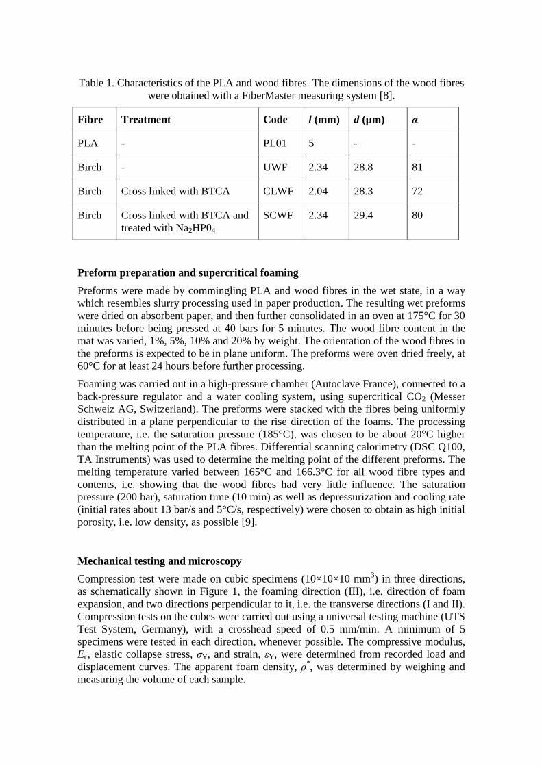
Table 1. Characteristics of the PLA and wood fibres. The dimensions of the wood fibres
were obtained with a FiberMaster measuring system [8].
Fibre Treatment Code l (mm) d (µm) α
PLA - PL01 5 - -
Birch - UWF 2.34 28.8 81
Birch Cross linked with BTCA CLWF 2.04 28.3 72
Birch Cross linked with BTCA and
treated with Na2HP04
SCWF 2.34 29.4 80
Preform preparation and supercritical foaming
Preforms were made by commingling PLA and wood fibres in the wet state, in a way
which resembles slurry processing used in paper production. The resulting wet preforms
were dried on absorbent paper, and then further consolidated in an oven at 175°C for 30
minutes before being pressed at 40 bars for 5 minutes. The wood fibre content in the
mat was varied, 1%, 5%, 10% and 20% by weight. The orientation of the wood fibres in
the preforms is expected to be in plane uniform. The preforms were oven dried freely, at
60°C for at least 24 hours before further processing.
Foaming was carried out in a high-pressure chamber (Autoclave France), connected to a
back-pressure regulator and a water cooling system, using supercritical CO2 (Messer
Schweiz AG, Switzerland). The preforms were stacked with the fibres being uniformly
distributed in a plane perpendicular to the rise direction of the foams. The processing
temperature, i.e. the saturation pressure (185°C), was chosen to be about 20°C higher
than the melting point of the PLA fibres. Differential scanning calorimetry (DSC Q100,
TA Instruments) was used to determine the melting point of the different preforms. The
melting temperature varied between 165°C and 166.3°C for all wood fibre types and
contents, i.e. showing that the wood fibres had very little influence. The saturation
pressure (200 bar), saturation time (10 min) as well as depressurization and cooling rate
(initial rates about 13 bar/s and 5°C/s, respectively) were chosen to obtain as high initial
porosity, i.e. low density, as possible [9].
Mechanical testing and microscopy
Compression test were made on cubic specimens (10×10×10 mm3) in three directions,
as schematically shown in Figure 1, the foaming direction (III), i.e. direction of foam
expansion, and two directions perpendicular to it, i.e. the transverse directions (I and II).
Compression tests on the cubes were carried out using a universal testing machine (UTS
Test System, Germany), with a crosshead speed of 0.5 mm/min. A minimum of 5
specimens were tested in each direction, whenever possible. The compressive modulus,
Ec, elastic collapse stress, σY, and strain, εY, were determined from recorded load and
displacement curves. The apparent foam density, ρ*, was determined by weighing and
measuring the volume of each sample.

Figure 1. : Schematic representation prepared specimens in relation to the foaming (rise)
direction of the sample.
Scanning electron microscopy (SEM) was used to examine the microstructure of the
wood fibre composite foams. Razor blade cut samples were carbon coated with a high
vacuum carbon coater (Cressington 208) and were observed with a microscope (Philips
XL30) in secondary electron mode at an accelerating voltage of 3 kV. Two specimens
from each sample were observed for each of the three perpendicular spatial directions.
Image analysis was carried out using the open source software ImageJ [10], which
offers the possibility of extracting quantitative information from the porous structure.
The Feret’s diameter, i.e. the measured distance between theoretical parallel lines that
are drawn tangent to the cell profile in the micrograph, was used as a measure of the
average cell size. This measure can also be used to obtain an estimate of the average cell
wall thickness and cell density together with the foam porosity [11].
MICROMECHANICAL MODELLING
The mechanical properties of two phase foams (polymer/cell) can be related to the foam
density, whilst the cellular nature of the microstructure determines the mode of failure
under stress [12]. In this work it is desirable to analyse the three-phase foam
(polymer/fibre/cell) and predict the reinforcement effect of the wood fibres. It has
previously been shown that the concept of laminate analogy can be used to predict the
modulus of high density reinforced foams [13]. A similar approach will be used here
and will be briefly described in the following. The fundamental idea and assumption is
that the foam can be treated as homogenous material with the effective properties of a
foam. It is further assumed the wood fibres are randomly distributed in the plane with
normal direction III.
The laminate analogy approach is based on modelling composites reinforced by
nonaligned discontinuous fibres by using the classical lamination theory for a stack of
unidirectional layers, each of which accounts, for one fibre orientation. In this way, the
modulus of a wide range of nonaligned short-fibre reinforced composite can be
estimated, e.g. [14]. The modulus of a composite with fibres uniformly oriented in-plane
can be written like
2 2
1 4c
1
U UE
U
(1)
where U1 and U4 are well known laminate invariants defined as
U1 3
8Q11
3
8Q22
1
4Q12
1
2Q66 (2)
U4 1
8Q11
1
8Q22
3
4Q12
1
2Q66 (3)
where Q11, Q22, Q12 and Q16 are components of the stiffness matrix of a laminate with
perfectly aligned fibres. These are related to engineering constants as Q11 = EL/(1 –
νLTνTL), Q22 = ET/(1 – νLTνTL), Q12 = LTET/(1 – νLTνTL) and Q66 = GLT, where
TL = νLTET/ EL. The longitudinal and transverse Young’s modulus of the lamina are
denoted EL and ET, respectively. The major Poisson ratio is denoted νLT and the shear
modulus GLT. The properties of the lamina (EL, ET, GLT, νLT) can be obtained from the
properties of its constituents (fibre and matrix) using a micromechanical model. The
Halpin-Tsai equations [15] can be applied to short fibre composites as
f1
m f1
1
1
VM
M V
(4)
(Mf /Mm )1
(Mf /Mm ) (5)
where M, Mf and Mm represent the moduli, listed in Table 2, which also gives he
parameter , and change depending on which lamina modulus is sought. The volume
fraction of the wood fibres contained in cell walls of the foam composite is represented
by Vf1.
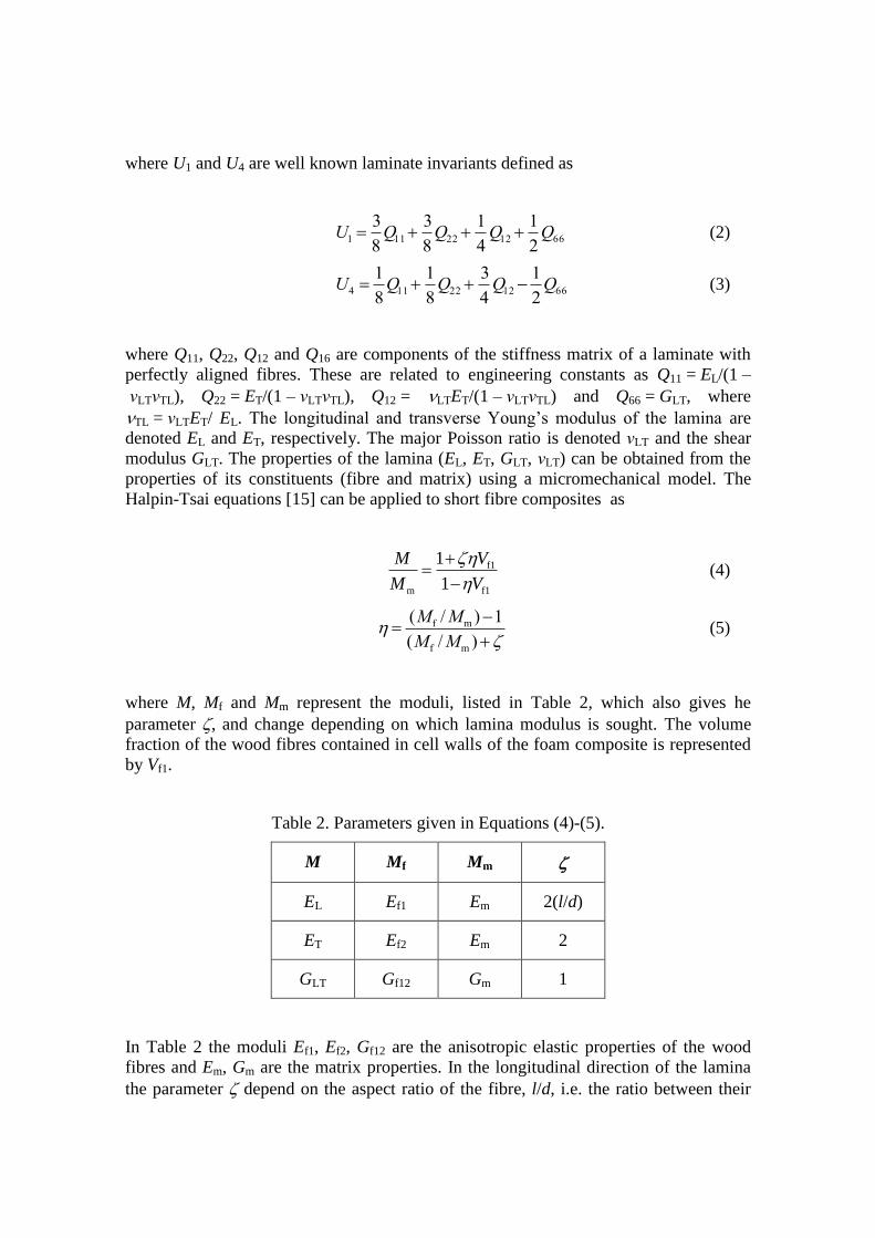
Table 2. Parameters given in Equations (4)-(5).
M Mf Mm
EL Ef1 Em 2(l/d)
ET Ef2 Em 2
GLT Gf12 Gm 1
In Table 2 the moduli Ef1, Ef2, Gf12 are the anisotropic elastic properties of the wood
fibres and Em, Gm are the matrix properties. In the longitudinal direction of the lamina
the parameter depend on the aspect ratio of the fibre, l/d, i.e. the ratio between their
length, l, and diameter, d, which is given in Table 1. The Poisson ratio, νLT, can be
obtained from the rule of mixture,
LT fVf1 m(1Vf1) (6)
where νf12 and νm are the Poisson ratios of the wood fibres and matrix, respectively. So
far, the model described can be applied for any type of short fibre composites with a
uniform fibre orientation distribution. To adapt the model to fibre reinforced foams, it is
assumed that the matrix material (in Table 2) can be described by the Gibson-Ashby
relation [12] for open cell foams
2
m PLA p(1 )E E V (7)
where EPLA is the modulus of solid PLA and Vp is the porosity of the foam. Equations
(1)-(7) can now be used to estimate the modulus of short fibre reinforced foams as
function of Vp and Vf1. It is necessary to know the fibre properties, the matrix properties
and the relation between Vp-Vf1 to be able to predict the foam composite modulus. The
relation between Vf1 and Vp can be written
Vf1 Vf (1Vp) (8)
where Vf is the fibre volume fraction in the preform, i.e. before foaming. This can be
obtained from the weight fraction Wf as
Vf cfWf (9)
c fVf PLA(1Vf ) (10)
where f and PLA are the density of the fibres and solid PLA matrix. The volume
fraction of porosity in Equations (7)-(8) is obtained from the relative density as
Vp 1*
c (11)
where * is the density of the foam composite and c the density of the bulk composite.

RESULTS AND DISUCSSION
Morphology
SEM provided qualitative as well as quantitative microstructural data useful for
understanding structural formation during processing and building an appropriate
micromechanical model.
All foams displayed a rather large dispersion in cell size, in particular the pure PLA
foams and the composite foams with 1 wt% wood fibres (see Figure 2 for foams with
UWF). No significant impact of wood fibre treatment on cell morphology was seen. The
micrographs shown in Figure 2 for foams with UWF can be considered representative
for each composition for all surface treatments. The evolution in structure and
morphology at higher wood fibre contents can clearly be seen in Figure 2. As the fibre
content increased the cell size decreased, although a few large and extremely elongated
pores are visible in planes with normal direction I and II. With image analysis an
interesting trend was observed, and considering the pure PLA case as separate
(homogeneous cell nucleation), an increase in wood fibre content implied smaller cell
sizes (measured as the Feret diameter) in all cases, confirmed what was apparent on the
micrographs (Figure 2). Again it was not possible to distinguish if wood fibre treatments
had a significant effect on the values measured for the cell sizes since all cases were
largely comparable, within experimental uncertainty.
1% wt 5% wt 10% wt
Figure 2. Microstructure of foams with UWF for different fibre content. The direction
of the normal of the plane of view is indicated, i.e. I-II show a plane in the foaming
direction, and III a plane perpendicular to it.
Micrographs in the plane perpendicular to the foaming direction, i.e. normal direction
III, revealed significant amounts of fibres, only for fibre contents higher than 1 wt%
(Figure 2). It appeared that the fibres had remained in this particular plane and were not
considerably disrupted by the foaming. The density of wood fibres was quite impressive
and very few fairly regular shaped cells were seen on these planes. Moreover fibres in
II
III
I II
III III

foams with up to 10 wt% appeared to be well wetted, none of them sticking out bare and
they remained mainly uniformly oriented in the plane perpendicular to the foaming
direction. It was clear that for all the foams the fibres mainly stayed in plane I-II. The
driving force for cell growth is induced by the pressure difference, between the cell and
the external pressure. This force is opposed mainly by the resistance of the material
surrounding the cell governed by the elongational viscosity. The wood fibres were
randomly oriented in plane I-II, perpendicular to the foaming direction, and create a
network of fibres in this plane. It is likely that the cells expand easier in the foaming
direction and the perpendicular directions in-between the wood fibre layers, which form
a network more difficult to deform. This could also explain the observation of large
cells oriented perpendicular to the foaming direction, especially in foams with higher
wood fibre content.
The microstructure at high fibre content, 20 wt%, changed. SEM micrographs showed
there was too little PLA matrix to perfectly wet all the fibres (Figure 3). Fibres jutting
out of the surface of planes with normal in direction I and II were visible, indicating that
they have essentially remained in the plane perpendicular to the foaming direction.
Figure 3 confirms that the specimens with 20 wt% wood fibres were not foams as the
fibres were incompletely impregnated, and the structure resembled more the one of
simple fibre mat.
Figure 3. Micrograph of foam with 20 wt% UWF showing insufficient fibre
impregnation.
An estimation of the fibre diameter using Figure 3 gives values ranging from 20-30 m,
which are in agreement with the measurements in Table 1. A high degree of orientation
similar to the stacking of layers in the commingled preforms before initial compaction
was visible. This suggests that the pre-compaction was not sufficient and during heating
in the autoclave the preform might expand due to release of internal stresses. This
would obviously cause large voids in the preform (as was seen between different wood

fibre layers and perpendicular to the foaming direction) before saturation temperature
and pressure are reached in the autoclave. Upon venting the gas will probably follow
these fast paths out of the material, not contributing to any cell formation.
The main conclusion from the SEM study is that the presence of wood fibres gave rise
to a change in the foam morphology. The foam microstructure was highly
inhomogeneous. The preforms had a layered structure and cell formation took place
mainly in between the layered wood fibre networks. In many cases it was found that
large foam cells or macro-pores were elongated perpendicular to the foaming direction.
Generally good wetting of the wood fibres by the PLA matrix was noticed. The wood
fibres remained oriented uniformly in the plane perpendicular to the foaming direction
as in the preform before the foaming. Addition of 10 wt% wood fibres seemed to be a
limit to obtain foams, with the used processing conditions.
Density and mechanical properties
The results of the density measurements are shown against weight fraction of wood
fibres in Figure 4. There was an increase in density, for all fibre treatments, from 1 wt%
to 10 wt% fibre content. The materials with 20 wt% which cannot be considered as
foams had lower densities then the reinforced foams. The decrease in density for foams
with 1 wt% wood fibres could be due to increased nucleation but also because of
insufficient viscosity which could lead to cell coalescence. The different fibre
treatments seem to reduce the density increase. This effect is slightly higher for SCWF
which were treated in a way to form a weaker wood fibre network in the preform. This
could allow for more foam expansion as compared with CLWF and UWF reinforced
foams.
Figure 4. Foam density as function of the weight fraction in the preforms.
Values of the Feret diameter obtained from image analysis were used together with the
density data in Figure 4 to approximate the average cell wall thickness. Results showed
that average cell wall thicknesses in between boundaries of 15–45 μm, with the overall
trend following what has already been seen for density, i.e. increase with wood fibre
content. These values are of the same order as the wood fibre sizes. Higher value of the
cell wall thickness might reasonably be expected to fully sheath the fibres but, the
estimate for has not been found to be much smaller than the fibre dimensions. It was
also found that the density of cells is approximately of 4∙104 cells/cm
3, which is
comparable to conventional reported values of 102–10
3 cells/cm
3. However, it should be
mentioned that the Feret diameters obtained with image analysis were lower than
approximate made directly on SEM micrographs, leading to an underestimation of the
cell wall thickness and an overestimation of the number of cells.
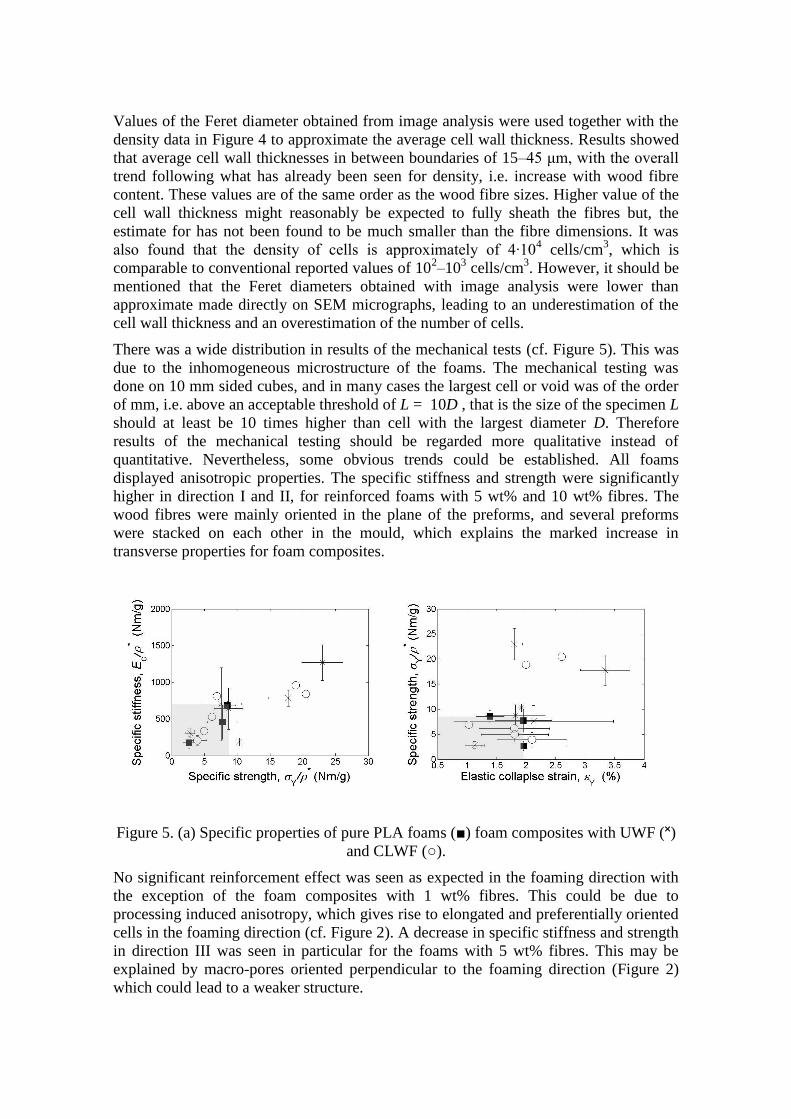
There was a wide distribution in results of the mechanical tests (cf. Figure 5). This was
due to the inhomogeneous microstructure of the foams. The mechanical testing was
done on 10 mm sided cubes, and in many cases the largest cell or void was of the order
of mm, i.e. above an acceptable threshold of L = 10D , that is the size of the specimen L
should at least be 10 times higher than cell with the largest diameter D. Therefore
results of the mechanical testing should be regarded more qualitative instead of
quantitative. Nevertheless, some obvious trends could be established. All foams
displayed anisotropic properties. The specific stiffness and strength were significantly
higher in direction I and II, for reinforced foams with 5 wt% and 10 wt% fibres. The
wood fibres were mainly oriented in the plane of the preforms, and several preforms
were stacked on each other in the mould, which explains the marked increase in
transverse properties for foam composites.
Figure 5. (a) Specific properties of pure PLA foams (■) foam composites with UWF (˟)
and CLWF (○).
No significant reinforcement effect was seen as expected in the foaming direction with
the exception of the foam composites with 1 wt% fibres. This could be due to
processing induced anisotropy, which gives rise to elongated and preferentially oriented
cells in the foaming direction (cf. Figure 2). A decrease in specific stiffness and strength
in direction III was seen in particular for the foams with 5 wt% fibres. This may be
explained by macro-pores oriented perpendicular to the foaming direction (Figure 2)
which could lead to a weaker structure.
The results of the mechanical testing for foams with UWF and CLWF in all directions
are shown in Figure 5a-b as the specific properties, i.e. Ec / ρ* vs. σY / ρ
* (Figure 5a) and
σY / ρ* vs. εY (Figure 5b). The density of these foams is shown in Figure 4. The only
foams that present a significant increase in specific stiffness and strength as compared
with neat PLA foams in Figure 5a are the foams with 5 wt% and 10 wt% fibres in the
transverse directions (I and II). In addition, a simultaneous increase in the elastic
collapse strain was noticed for foams with 10 wt% fibres (Figure 5b). The foams with
CLWF were stiffer and stronger than the corresponding foams with UWF, at 5 wt% but
not at 10 wt% fibre content. It has previously been shown that BTCA treated wood
fibres have higher stiffness as compared with untreated fibres [14]. Foams with SCWF
showed similar properties.
The micromechanical model which superposes the Gibson-Ashby relation [12] and the
Halpin-Tsai equations, Equations (1)-(11), was used to predict the stiffness of the foam
composites. Input data needed are the relation between foam porosity, Equation (11),
and volume fraction of the wood fibres in the preforms, Equation (8), as well as the
elastic parameters of the constituents. The Young’s modulus of PLA, EPLA = 2.2 GPa,
was obtained with Equation (7) using experimental data for pure PLA foams in
direction I and II. The longitudinal stiffness, Ef1, for the UWF and both the treated fibres
were taken from Neagu et al. [14], as 35 GPa and 40 GPa, respectively. The Poisson
ratios were chosen to m = 0.3 and f12 = 0.3, and the needed anisotropic properties,
Ef2/Ef1 = 0.125 and Gf12/Ef1 = 0.1, were based on values found in literature [14].
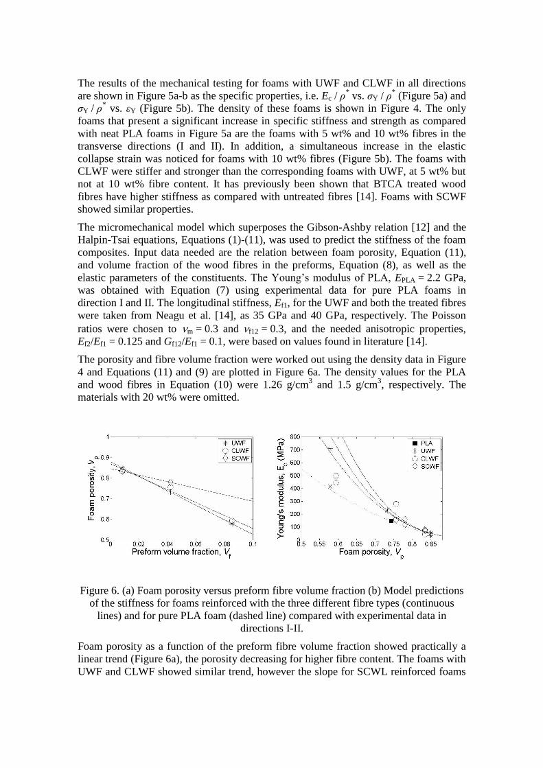
The porosity and fibre volume fraction were worked out using the density data in Figure
4 and Equations (11) and (9) are plotted in Figure 6a. The density values for the PLA
and wood fibres in Equation (10) were 1.26 g/cm3 and 1.5 g/cm
3, respectively. The
materials with 20 wt% were omitted.
Figure 6. (a) Foam porosity versus preform fibre volume fraction (b) Model predictions
of the stiffness for foams reinforced with the three different fibre types (continuous
lines) and for pure PLA foam (dashed line) compared with experimental data in
directions I-II.
Foam porosity as a function of the preform fibre volume fraction showed practically a
linear trend (Figure 6a), the porosity decreasing for higher fibre content. The foams with
UWF and CLWF showed similar trend, however the slope for SCWL reinforced foams

was lower. The lower slope is the more is the amount of fibres can be added for a given
relative density or porosity. It was previously mentioned that the surfactant treated cross
linked fibres are less bound and form a weaker network probably allowing for more
foam expansion, hence lower relative density (Figure 4) or higher porosity (Figure 6a).
The reinforcement potential increases with increased fibre stiffness (cross linked fibres
have higher stiffness) and increased aspect ratio. Even so, the key factor is the relation
between, foam porosity and fibre volume fraction in the preform shown in Figure 6a,
the higher the slope of the linear relation Vp-Vf is the more reinforcement is obtained.
CONCLUSIONS
Foams with different fibre content and treatment were produced using supercritical CO2
from a stack of preforms done by a wet process and composed of wood and PLA fibres.
The fibres were oriented randomly in-plane and perpendicular to the foaming direction.
The addition of fibres had a strong effect on microstructure of the foams. With the
processing conditions used in this work the limit of maximal fibre fraction that can be
added was 10 wt%.
Reinforced foams were anisotropic and stiffer in the directions where wood fibres were
uniformly dispersed than in the foaming direction. No significant difference was
observed between the UWF and CLWF reinforced foams. Foams with SCWF had lower
relative density, i.e. higher porosity, for the same foam morphology and were easier to
expand. The key factor for reinforcement is the relation between, foam porosity (relative
density) and fibre volume fraction in the preform.
The foaming conditions have to be adapted for each wood fibre content to obtain foam
with the desired porosity. To maximise the reinforcement effect, foams have to be done
in a way so the porosity does not decrease to a large extent with increased wood fibre
fraction. Changing the viscosity of the matrix and fibre treatment, i.e. like the surfactant
treatment used in this study, could help. Another solution could be to make foams with
smaller cells and higher cell density, by increasing the cooling rate and depressurization
rate.
ACKNOWLEDGEMENTS
Financial support from the SustainComp project within the Seventh Research
Framework Programme (FP7) of the European Union (EU) is greatly acknowledged.
The authors would like to thank Thomas Gascou and Carole Boissard for contribution
on the experimental part and fruitful discussions.
References
[1] Mathieu LM, Montjovent MO, Bourban PE, Pioletti DP, Månson J-AE.
Bioresorbable composites prepared by supercritical fluid foaming. Journal of
Biomedical Materials Research Part A 2005;75A(1):89-97.
[2] Garlotta D. A literature review of poly(lactic acid). Journal of Polymers and the
Environment 2001;9(2):63-84.

[3] Svagan AJ, Samir M, Berglund LA. Biomimetic polysaccharide nanocomposites
of high cellulose content and high toughness. Biomacromolecules 2007;8(8):2556-2563.
[4] Nalawade SP, Picchioni F, Janssen LPBM. Supercritical carbon dioxide as a
green solvent for processing polymer melts: Processing aspects and applications.
Progress in Polymer Science 2006;31(1):19-43.
[5] Rachtanapun P, Selke SEM, Matuana LM. Microcellular foam of polymer
blends of HDPE/PP and their composites with wood fiber. Journal of Applied Polymer
Science 2003;88(12):2842-2850.
[6] Di YW, Iannace S, Di Maio E, Nicolais L. Poly(lactic acid)/organoclay
nanocomposites: Thermal, rheological properties and foam processing. Journal of
Polymer Science Part B-Polymer Physics 2005;43(6):689-698.
[7] Zhou YJ, Luner P, Caluwe P. Mechanism of Crosslinking of Papers with
Polyfunctional Carboxylic Acids. Journal of Applied Polymer Science
1995;59(9):1523–1534.
[8] Karlsson H, Fransson PI. STFI Fibermaster Gives Papermakers New Muscle -
New Knowledge Concerning Fiber Shape Can Be the Key to Paper of the Future.
Svensk Papperstidning - Nordisk Cellulosa 1994;97(10):26-28.
[9] Bühler M, Bourban PE, Manson JAE. Cellular thermoplastic composites with
microstructural gradients of fibres and porosity. Compos. Sci. Technol. 2008;68(3-
4):820-828.
[10] Rasband WS. ImageJ (http://rsb.info.nih.gov/ij/). Bethesda, Maryland, USA:
U.S. National Institutes of Health, 1997 – 2007.
[11] Shutov FA. Cellular structure and properties of foamed polymers. In: Klempner
D, Frisch KC, editors. Handbook of Polymeric foams and Foam Technology. Hanser
Publishers, 1991.
[12] Gibson LJ, Ashby MF. Cellular solids : structure and properties. Cambridge ;
New York: Cambridge University Press, 1997.
[13] Masi P, Nicolais L, Mazzola M, Narkis M. Tensile Properties of Fiberglass-
Reinforced Polyester Foams. Journal of Applied Polymer Science 1983;28(4):1517-
1525.
[14] Neagu RC, Gamstedt EK, Berthold F. Stiffness contribution of various wood
fibers to composite materials. Journal of Composite Materials 2006;40(8):663-699.
[15] Chou T-W. Microstructural design of fiber composites. Cambridge, 2005.


![The wood fibre equivalent [m³ (f)] an introduction · 2015-04-02 · 17.03.2015 Slide 1 Geneva Holger Weimar The wood fibre equivalent [m³ (f)] Dr. Holger Weimar Thünen Institute](https://static.fdocuments.us/doc/165x107/5f42be73a9b4c77d2c382f0b/the-wood-fibre-equivalent-m-f-an-introduction-2015-04-02-17032015-slide.jpg)