PROCESS OVERVIEW - RWTH Aachen University
12
Project : 2018 AEC Hackathon Geometry Robotic Production Toolpath Planes Toolpath Curves Robot Trajectory Re-oriented Planes Approach & Retract PROCESS DESIGN PRODUCTION PROCESS OVERVIEW
Transcript of PROCESS OVERVIEW - RWTH Aachen University

Project : 2018 AEC Hackathon
GeometryRobotic
ProductionToolpathPlanes
ToolpathCurves
Robot Trajectory
Re-oriented Planes
Approach & Retract
PROCESSDESIGN PRODUCTION
PROCESS OVERVIEW
Project : 2018 AEC Hackathon
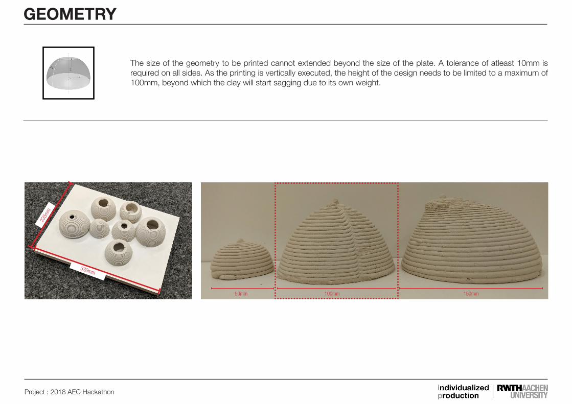
The size of the geometry to be printed cannot extended beyond the size of the plate. A tolerance of atleast 10mm is required on all sides. As the printing is vertically executed, the height of the design needs to be limited to a maximum of 100mm, beyond which the clay will start sagging due to its own weight.
GEOMETRY
50mm
320mm
235m
m
100mm 150mm

SphereGenerating a sphere to get a dome by cutting the sphere in half.
Solid DifferenceCreating the dome.
ExtrudeCreate the subtracting geometry by extruding the rectangle.
RectangleCreate a rectangle to create the subtracting geometry.
Origin Point
Origin Plane
Dome
Project : 2018 AEC Hackathon
GEOMETRY
Project : 2018 AEC Hackathon
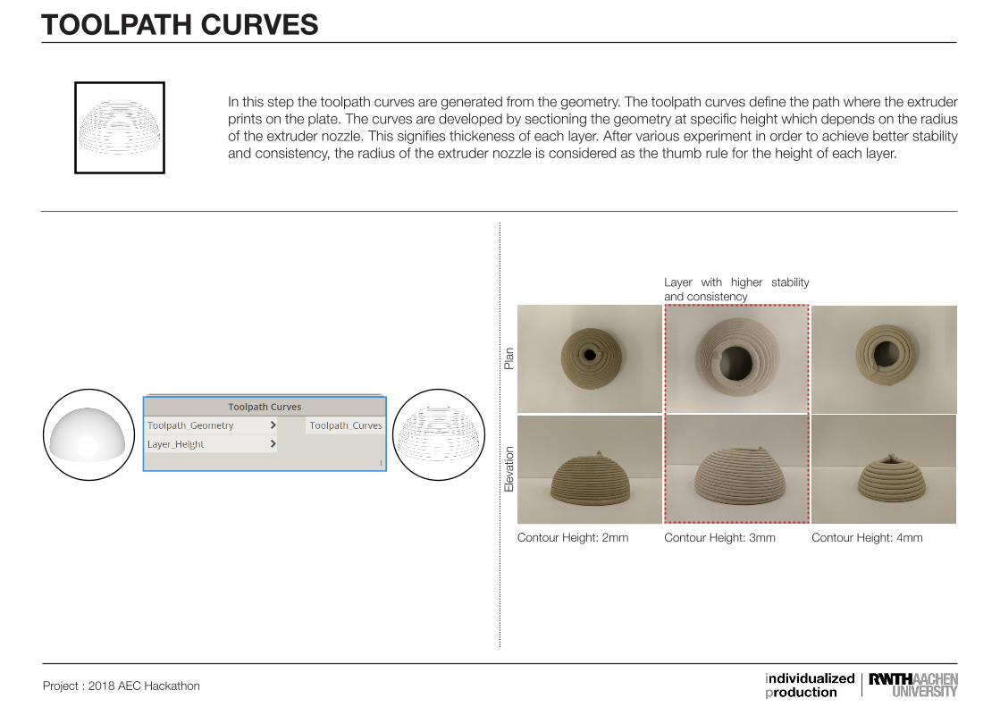
Contour Height: 4mm
Pla
nE
leva
tion
Contour Height: 3mmContour Height: 2mm
Layer with higher stability and consistency
TOOLPATH CURVES
In this step the toolpath curves are generated from the geometry. The toolpath curves define the path where the extruder prints on the plate. The curves are developed by sectioning the geometry at specific height which depends on the radius of the extruder nozzle. This signifies thickeness of each layer. After various experiment in order to achieve better stability and consistency, the radius of the extruder nozzle is considered as the thumb rule for the height of each layer.
Project : 2018 AEC Hackathon
TOOLPATH CURVES
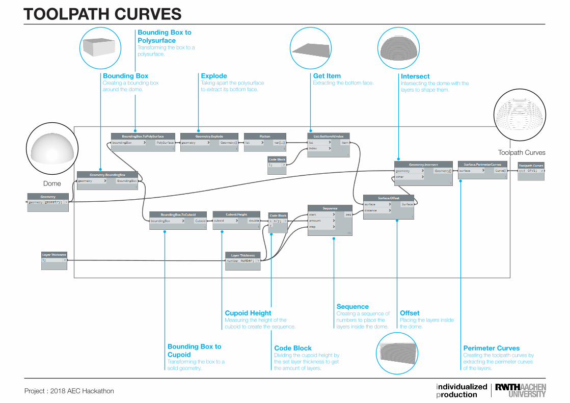
ExplodeTaking apart the polysurface to extract its bottom face.
Get ItemExtracting the bottom face.
IntersectIntersecting the dome with the layers to shape them.
Bounding Box to CupoidTransforming the box to a solid geometry.
Code BlockDividing the cupoid height by the set layer thickness to get the amount of layers.
OffsetPlacing the layers inside the dome.
Perimeter CurvesCreating the toolpath curves by extracting the perimeter curves of the layers.
Toolpath Curves
Dome
Bounding Box to PolysurfaceTransforming the box to a polysurface.
SequenceCreating a sequence of numbers to place the layers inside the dome.
Bounding BoxCreating a bounding box around the dome.
Cupoid HeightMeasuring the height of the cuboid to create the sequence.

Project : 2018 AEC Hackathon
TOOLPATH PLANES
In this step the toolpath planes are generated from the toolpath curves. Although the toolpath curves define the path for the extruder to travel, as the robot allows 6 degrees of freedom(DOF) the oritentation of tip of the extruder with respect to the plate. For easier understanding the experiement is conducted only with 3 DOF i.e on the same plane.
PlanSimulationToolpath - Custom NodeToolpath
3DOF
6DOF
Elevation
Layers with twist
Layers more smooth

Project : 2018 AEC Hackathon
TOOLPATH PLANES - 3DOF
Start Point & End PointExtracting the start and end points of the toolpath curves to generate its planes.
List CreateCombining start and end points with the dividing segment points of the toolpath curves to one list as origin for the toolpath planes.
Curve LengthMeasuring the lengths of toolpath curves to divide each curve in equal segments.
PlaneCreating toolpath planes on the toolpath curves.
Toolpath Planes
Points Equal Segment LengthDividing toolpath curves in equal segments and extracting the points.
Plane Normal & Plane X AxisExtracting normal and x axis from the world plane to create the toolpath planes.
Toolpath Curves
Project : 2018 AEC Hackathon
APPROACH & RETRACT
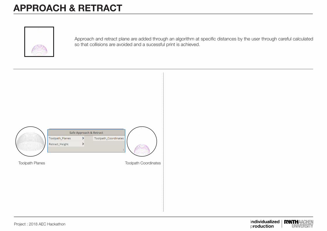
Approach and retract plane are added through an algorithm at specific distances by the user through careful calculated so that collisions are avoided and a sucessful print is achieved.
Toolpath Planes Toolpath Coordinates

Project : 2018 AEC Hackathon
First ItemExtracting the first coordinate to create the start point for the safe retract.
Geometry TranslateMoving the first coordinate by the set length to create the toolpath start point.
List CreateCombining the coordinates with the moved start and end coordinates to one list.
Last ItemExtracting the last coordinate to create the end point for the safe retract.
Geometry TranslateMoving the last coordinate by the set length to create the toolpath end point.
Toolpath Coordinates
Toolpath Planes
Plane to Coordinate SystemTransforming the toolpath planes to coordinates.
Z AxisExtracting the z axis of the coordinate system as direction to move the first coordinates.
Z AxisExtracting the z axis of the coordinate system as direction to move the last coordinates.
APPROACH & RETRACT
Project : 2018 AEC Hackathon
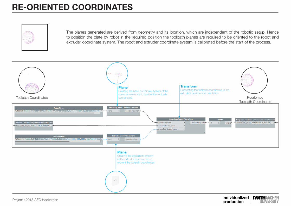
PlaneCreating the base coordinate system of the dome as reference to reorient the toolpath coordinates.
TransformReorienting the toolpath coordinates to the extruders position and orientation.
PlaneCreating the coordinate system of the extruder as reference to reorient the toolpath coordinates.
Reoriented Toolpath Coordinates
Toolpath Coordinates
RE-ORIENTED COORDINATES
The planes generated are derived from geometry and its location, which are independent of the robotic setup. Hence to position the plate by robot in the required position the toolpath planes are required to be oriented to the robot and extruder coordinate system. The robot and extruder coordinate system is calibrated before the start of the process.
Project : 2018 AEC Hackathon
ROBOTIC TRAJECTORY
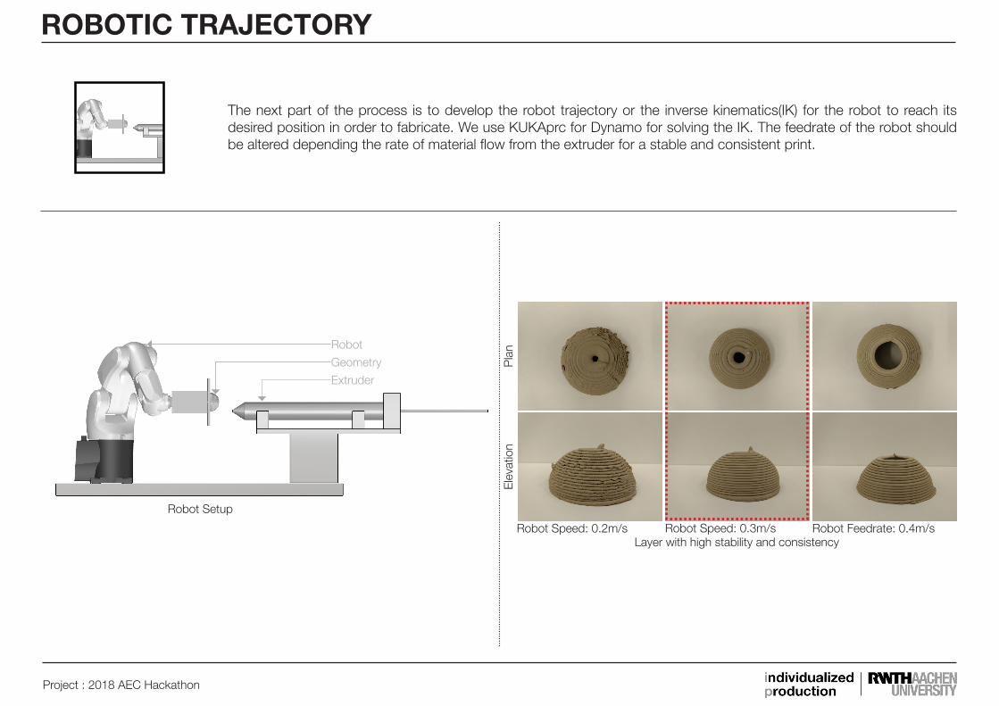
The next part of the process is to develop the robot trajectory or the inverse kinematics(IK) for the robot to reach its desired position in order to fabricate. We use KUKAprc for Dynamo for solving the IK. The feedrate of the robot should be altered depending the rate of material flow from the extruder for a stable and consistent print.
Pla
nE
leva
tion
Robot Feedrate: 0.4m/sRobot Speed: 0.2m/s Robot Speed: 0.3m/sLayer with high stability and consistency
Robot Setup
Extruder
Geometry
Robot
Project : 2018 AEC Hackathon
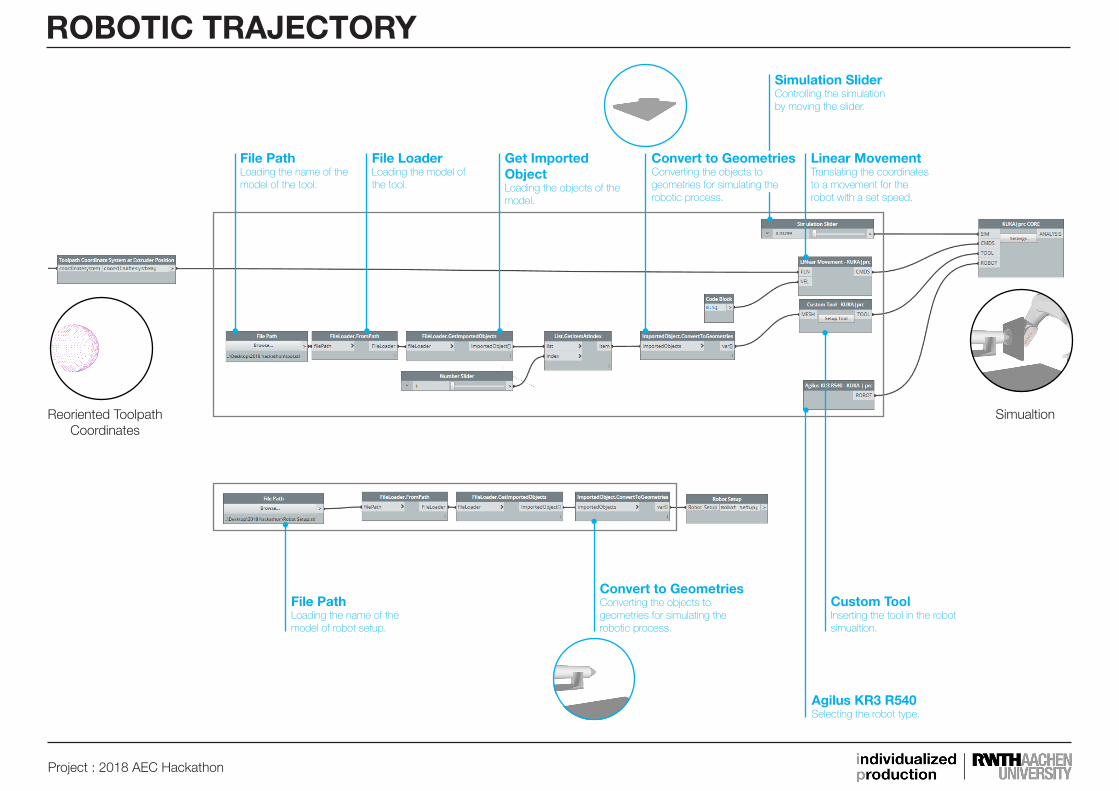
ROBOTIC TRAJECTORY
File PathLoading the name of the model of the tool.
Get Imported ObjectLoading the objects of the model.
Simulation SliderControlling the simulation by moving the slider.
Linear MovementTranslating the coordinates to a movement for the robot with a set speed.
File PathLoading the name of the model of robot setup.
Agilus KR3 R540Selecting the robot type.
Simualtion
Convert to GeometriesConverting the objects to geometries for simulating the robotic process.
Custom ToolInserting the tool in the robot simualtion.
Reoriented Toolpath Coordinates
File LoaderLoading the model of the tool.
Convert to GeometriesConverting the objects to geometries for simulating the robotic process.