PROCESS HEAT EXCHANGER - BORSIGzm.borsig.de/uploads/tx_empageflip/BORSIG_Process... · BORSIG...
20
BORSIG PROCESS HEAT EXCHANGER PROCESS GAS WASTE HEAT RECOVERY SYSTEMS PROCESS GAS WASTE HEAT RECOVERY SYSTEMS A Member of KNM Group Berhad
Transcript of PROCESS HEAT EXCHANGER - BORSIGzm.borsig.de/uploads/tx_empageflip/BORSIG_Process... · BORSIG...
BORSIGPROCESS HEAT EXCHANGER
PROCESS GAS WASTE HEATRECOVERY SYSTEMS
PROCESS GAS WASTE HEAT RECOVERY SYSTEMS
A Member of KNM Group Berhad
“Tunnelflow” Quench Coolers
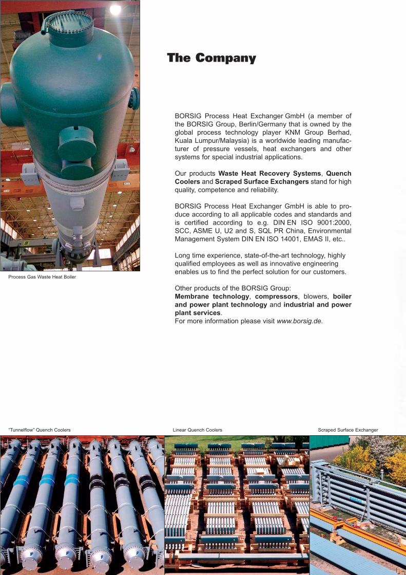
The Company
BORSIG Process Heat Exchanger GmbH (a member of
the BORSIG Group, Berlin/Germany that is owned by the
global process technology player KNM Group Berhad,
Kuala Lumpur/Malaysia) is a worldwide leading manufac-
turer of pressure vessels, heat exchangers and other
systems for special industrial applications.
Our products Waste Heat Recovery Systems, Quench
Coolers and Scraped Surface Exchangers stand for high
quality, competence and reliability.
BORSIG Process Heat Exchanger GmbH is able to pro-
duce according to all applicable codes and standards and
is certified according to e.g. DIN EN ISO 9001:2000,
SCC, ASME U, U2 and S, SQL PR China, Environmental
Management System DIN EN ISO 14001, EMAS II, etc..
Long time experience, state-of-the-art technology, highly
qualified employees as well as innovative engineering
enables us to find the perfect solution for our customers.
Other products of the BORSIG Group:
Membrane technology, compressors, blowers, boiler
and power plant technology and industrial and power
plant services.
For more information please visit www.borsig.de.
Linear Quench Coolers Scraped Surface Exchanger
Process Gas Waste Heat Boiler
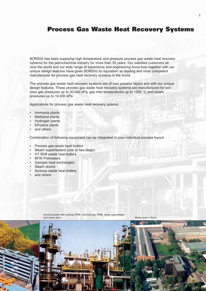
Process Gas Waste Heat Recovery Systems
BORSIG has been supplying high temperature and pressure process gas waste heat recovery
systems for the petrochemical industry for more than 35 years. Our satisfied customers all
over the world and our wide range of experience and engineering know-how together with our
unique design features have given BORSIG its reputation as leading and most competent
manufacturer for process gas heat recovery systems in the world.
The process gas waste heat recovery systems are of own process layout and with our unique
design features. These process gas waste heat recovery systems are manufactured for pro-
cess gas pressures up to 30,000 kPa, gas inlet temperatures up to 1200 °C and steam
pressures up to 14,000 kPa.
Applications for process gas waste heat recovery sytems:
• Ammonia plants
• Methanol plants
• Hydrogen plants
• Ethylene plants
• and others
Combination of following equipment can be integrated in your individual process layout:
• Process gas waste heat boilers
• Steam superheaters (one or two stage)
• HT Shift waste heat boilers
• BFW Preheaters
• Gas/gas heat exchangers
• Steam drums
• Synloop waste heat boilers
• and others.
Works area in Berlin
Ammonia plant with synloop WHB, reformed gas WHB, steam superheater
and steam drum
1

Configurations
2
Fig. 4: Arrangement of a waste heat boiler and
steam drum in a hydrogen plant
Fig. 5: Two parallel arranged WHBs are operating on
one common steam drum in the reformed gas section
of a 2,500 MTPD methanol plantFig. 3
Fig. 1, 2, 3: Typical configuration of a combined reformed and synthesis gas heat recovery system
1 - Reformed gas WHB
2 - HP steam superheater
3 - Steam drum
4 - Shift WHB
5 - Shift BFW preheater
6 - Synloop WHB
7 - Synloop BFW preheater
Fig. 1
Fig. 2

Process Gas Waste Heat Boilers
Stiffened Tubesheet Design
The principle of this design is explained in schematic
sketches hereafter.
The thin tubesheet with a thickness of 15-30 mm is rein-
forced by a stiffening system. The stiffener fingers are
machined out from the reinforcement plates. These
stiffener plates are welded to a forged ring which itself is
welded to the tubesheet flange ring. All stiffener fingers
are welded to the thin tubesheet.
The action/reaction forces through the stiffener system
are shown in Fig. 8.
The pressure load on the thin tubesheet caused by the
high steam side pressure is transferred from the thin
tubesheet through the stiffener fingers into the reinforce-
ment plates and via the forged ring and the tubesheet
flange ring into the shell. This results in elongation of the
shell which is close to the tube elongation by thermal
expansion. Therefore the resulting stresses in the tube
to tubesheet welds are low.
The stiffened tubesheet system is designed to absorb
the maximum pressure on gas side or steam side with
pressure on the other side being zero.
Presassembled stiffener system with integrated part of the
bypass tube Automatic welding of stiffener fingers to tubesheet with robot
Fig. 8: Action/reaction forces in stiffener system
Fig. 7: 3-D computer graphic model of
stiffened tubesheet system
Fig. 6: Pressure area reinforced by one finger
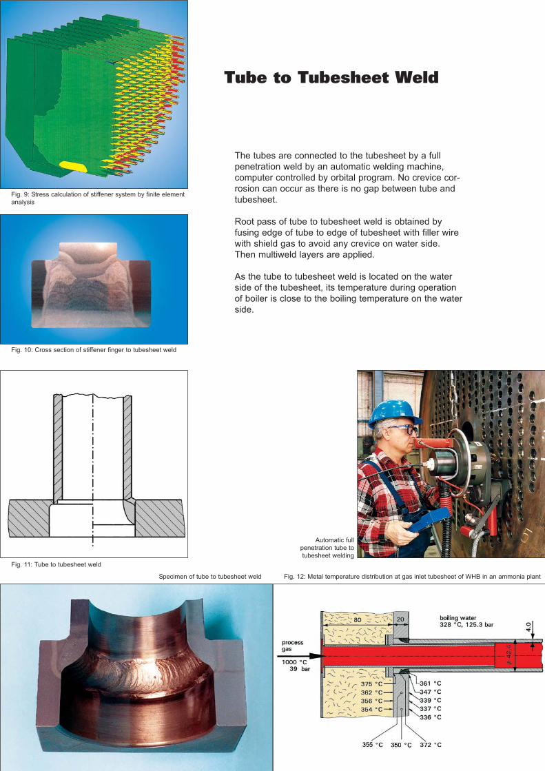
Tube to Tubesheet Weld
The tubes are connected to the tubesheet by a full
penetration weld by an automatic welding machine,
computer controlled by orbital program. No crevice cor-
rosion can occur as there is no gap between tube and
tubesheet.
Root pass of tube to tubesheet weld is obtained by
fusing edge of tube to edge of tubesheet with filler wire
with shield gas to avoid any crevice on water side.
Then multiweld layers are applied.
As the tube to tubesheet weld is located on the water
side of the tubesheet, its temperature during operation
of boiler is close to the boiling temperature on the water
side.
Automatic full
penetration tube to
tubesheet welding
Fig. 10: Cross section of stiffener finger to tubesheet weld
Fig. 9: Stress calculation of stiffener system by finite element
analysis
Specimen of tube to tubesheet weld Fig. 12: Metal temperature distribution at gas inlet tubesheet of WHB in an ammonia plant
Fig. 11: Tube to tubesheet weld
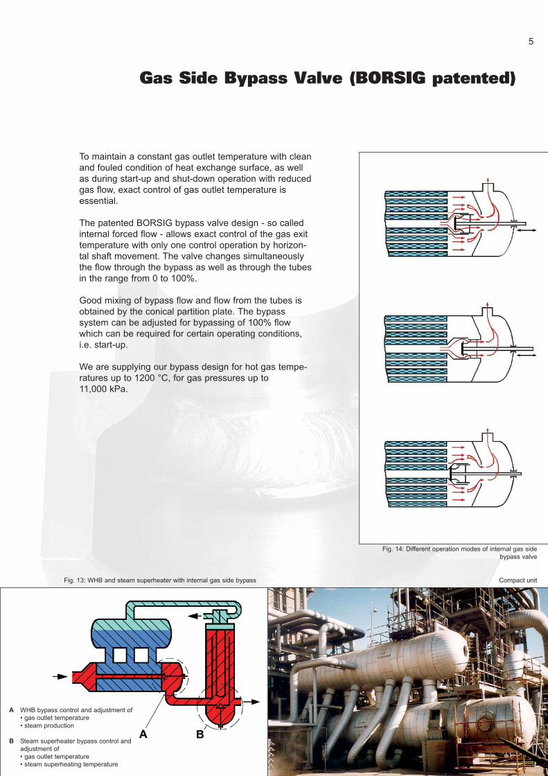
Gas Side Bypass Valve (BORSIG patented)
To maintain a constant gas outlet temperature with clean
and fouled condition of heat exchange surface, as well
as during start-up and shut-down operation with reduced
gas flow, exact control of gas outlet temperature is
essential.
The patented BORSIG bypass valve design - so called
internal forced flow - allows exact control of the gas exit
temperature with only one control operation by horizon-
tal shaft movement. The valve changes simultaneously
the flow through the bypass as well as through the tubes
in the range from 0 to 100%.
Good mixing of bypass flow and flow from the tubes is
obtained by the conical partition plate. The bypass
system can be adjusted for bypassing of 100% flow
which can be required for certain operating conditions,
i.e. start-up.
We are supplying our bypass design for hot gas tempe-
ratures up to 1200 °C, for gas pressures up to
11,000 kPa.
Fig. 13: WHB and steam superheater with internal gas side bypass Compact unit
Fig. 14: Different operation modes of internal gas side
bypass valve
A WHB bypass control and adjustment of
• gas outlet temperature
• steam production
B Steam superheater bypass control and
adjustment of
• gas outlet temperature
• steam superheating temperature
5
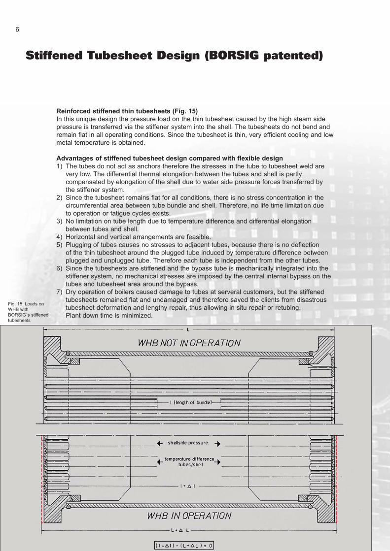
Stiffened Tubesheet Design (BORSIG patented)
Reinforced stiffened thin tubesheets (Fig. 15)
In this unique design the pressure load on the thin tubesheet caused by the high steam side
pressure is transferred via the stiffener system into the shell. The tubesheets do not bend and
remain flat in all operating conditions. Since the tubesheet is thin, very efficient cooling and low
metal temperature is obtained.
Advantages of stiffened tubesheet design compared with flexible design
1) The tubes do not act as anchors therefore the stresses in the tube to tubesheet weld are
very low. The differential thermal elongation between the tubes and shell is partly
compensated by elongation of the shell due to water side pressure forces transferred by
the stiffener system.
2) Since the tubesheet remains flat for all conditions, there is no stress concentration in the
circumferential area between tube bundle and shell. Therefore, no life time limitation due
to operation or fatigue cycles exists.
3) No limitation on tube length due to temperature difference and differential elongation
between tubes and shell.
4) Horizontal and vertical arrangements are feasible.
5) Plugging of tubes causes no stresses to adjacent tubes, because there is no deflection
of the thin tubesheet around the plugged tube induced by temperature difference between
plugged and unplugged tube. Therefore each tube is independent from the other tubes.
6) Since the tubesheets are stiffened and the bypass tube is mechanically integrated into the
stiffener system, no mechanical stresses are imposed by the central internal bypass on the
tubes and tubesheet area around the bypass.
7) Dry operation of boilers caused damage to tubes at serveral customers, but the stiffened
tubesheets remained flat and undamaged and therefore saved the clients from disastrous
tubesheet deformation and lengthy repair, thus allowing in situ repair or retubing.
Plant down time is minimized.
6
Fig. 15: Loads on
WHB with
BORSIG´s stiffened
tubesheets
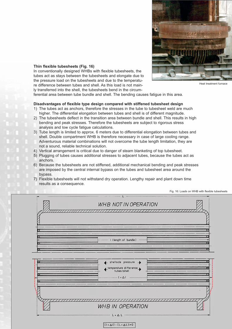
Thin flexible tubesheets (Fig. 16)
In conventionally designed WHBs with flexible tubesheets, the
tubes act as stays between the tubesheets and elongate due to
the pressure load on the tubesheets and due to the temperatu-
re difference between tubes and shell. As this load is not main-
ly transferred into the shell, the tubesheets bend in the circum-
ferential area between tube bundle and shell. The bending causes fatigue in this area.
Disadvantages of flexible type design compared with stiffened tubesheet design
1) The tubes act as anchors, therefore the stresses in the tube to tubesheet weld are much
higher. The differential elongation between tubes and shell is of different magnitude.
2) The tubesheets deflect in the transition area between bundle and shell. This results in high
bending and peak stresses. Therefore the tubesheets are subject to rigorous stress
analysis and low cycle fatigue calculations.
3) Tube length is limited to approx. 6 meters due to differential elongation between tubes and
shell. Double compartment WHB is therefore necessary in case of large cooling range.
Adventurous material combinations will not overcome the tube length limitation, they are
not a sound, reliable technical solution.
4) Vertical arrangement is critical due to danger of steam blanketing of top tubesheet.
5) Plugging of tubes causes additional stresses to adjacent tubes, because the tubes act as
anchors.
6) Because the tubesheets are not stiffened, additional mechanical bending and peak stresses
are imposed by the central internal bypass on the tubes and tubesheet area around the
bypass.
7) Flexible tubesheets will not withstand dry operation. Lengthy repair and plant down time
results as a consequence.
Heat treatment furnace
Fig. 16: Loads on WHB with flexible tubesheets
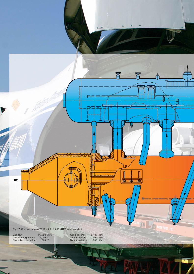
Fig. 17: Compact process WHB unit for 2,000 MTPD ammonia plant
Gas flow: Gas pressure:
Gas inlet temperature: Steam pressure:
Gas outlet temperature: Steam production:
275,000
1,000
360
kg/hr
°C
°C
3,400
13,000
280
kPa
kPa
t/h
9
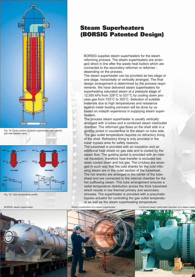
Steam Superheaters(BORSIG Patented Design)
BORSIG supplies steam superheaters for the steam
reforming process. The steam superheaters are arran-
ged direct in line after the waste heat boilers which are
connected to the secondary reformer or reformer -
depending on the process.
The steam superheater can be provided as two stage or
one stage, horizontally or vertically arranged. The final
design arrangement is determined by the process requi-
rements. We have delivered steam superheaters for
superheating saturated steam at a pressure stage of
12,500 kPa from 328°C to 531°C by cooling down pro-
cess gas from 723°C to 355°C. Selection of suitable
materials due to high temperatures and resistance
against metal dusting corrosion will be done by us
based on indepth experience in supplying steam super-
heaters.
The process steam superheater is usually vertically
arranged with U-tubes and a combined steam inlet/outlet
chamber. The reformed gas flows on the shell side in a
guiding jacket in counterflow to the steam on tube side.
The gas outlet temperature requires no refractory lining
of the shell. Refractory lining is only provided in the
lower bypass area for safety reasons.
The tubesheet is provided with an insulation and an
additional heat shield on gas side and is cooled by the
steam flow. The guiding jacket is provided with an inter-
nal insulation, therefore heat transfer is excluded bet-
ween cooled down and hot gas. The U-tubes are arran-
ged in such way that the cold shanks for the cold inflo-
wing steam are in the outer section of the tubesheet.
The hot shanks are arranged in the center of the tube-
sheet and are connected to the internal chamber for the
hot outflowing steam. This tube arrangement ensures a
radial temperature distribution across the thick tubesheet
which results in low thermal primary and secondary
stresses. The superheater is provided with a pneumatic
bypass actuator for controlling the gas outlet temperatu-
re as well as the steam superheating temperature.
Fig. 18: Cross section of steam superheater with internal
gas side bypass valve
Fig. 19: Tube temperature profile
BORSIG steam superheater Works construction of a steam superheater Combined steam inlet/outlet chamber of a steam super
heater
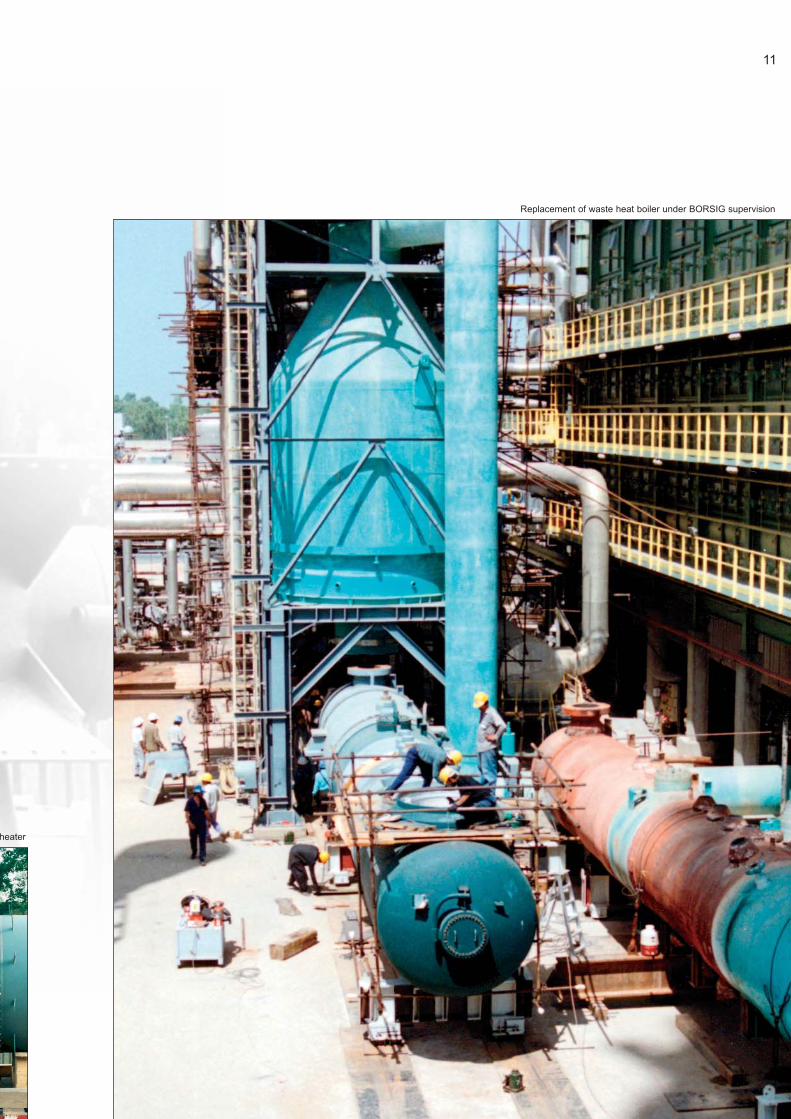
Replacement of waste heat boiler under BORSIG supervision
11
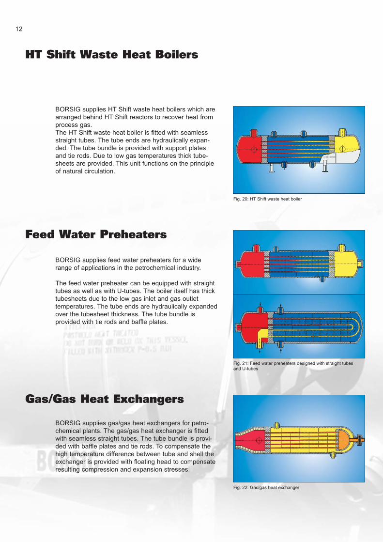
HT Shift Waste Heat Boilers
BORSIG supplies HT Shift waste heat boilers which are
arranged behind HT Shift reactors to recover heat from
process gas.
The HT Shift waste heat boiler is fitted with seamless
straight tubes. The tube ends are hydraulically expan-
ded. The tube bundle is provided with support plates
and tie rods. Due to low gas temperatures thick tube-
sheets are provided. This unit functions on the principle
of natural circulation.
12
BORSIG supplies feed water preheaters for a wide
range of applications in the petrochemical industry.
The feed water preheater can be equipped with straight
tubes as well as with U-tubes. The boiler itself has thick
tubesheets due to the low gas inlet and gas outlet
temperatures. The tube ends are hydraulically expanded
over the tubesheet thickness. The tube bundle is
provided with tie rods and baffle plates.
Gas/Gas Heat Exchangers
BORSIG supplies gas/gas heat exchangers for petro-
chemical plants. The gas/gas heat exchanger is fitted
with seamless straight tubes. The tube bundle is provi-
ded with baffle plates and tie rods. To compensate the
high temperature difference between tube and shell the
exchanger is provided with floating head to compensate
resulting compression and expansion stresses.
Fig. 20: HT Shift waste heat boiler
Fig. 21: Feed water preheaters designed with straight tubes
and U-tubes
Fig. 22: Gas/gas heat exchanger
Feed Water Preheaters

BORSIG supplies steam drums for high steam pressu-
res up to 16,500 kPa and steam flow rates up to 500
tons/hr. Steam drums are provided with demisters for
steam purification. Cyclones can be provided. All drums
are furnished with separation chambers for defined inter-
nal flows, with vortex breakers, thermosleeve nozzle for
BFW inlet, BFW distribution pipe system, chemical
dosing device, continous blow down pipe, instrumenta-
tion nozzles and oval manholes with self-tightening pres-
sure sealing covers.
We can deliver the steam drum with complete instru-
mentation.
Steam Drums
BORSIG supplies steam attemperators for controlling
the superheated steam temperature. Steam attempera-
tors can be integrated into the steam drums or designed
as separate unit connected to the steam drum by down-
comer and riser piping and function on the principle of
natural circulation like a single waste heat recovery boi-
ler. Steam temperature can be controlled by an internal
bypass valve.
Fig. 24: Steam attemperator integrated into steam drum
Fig. 25: Steam attemperator designed as separate unit
Fig. 23: Steam drum
13
Steam Attemperators
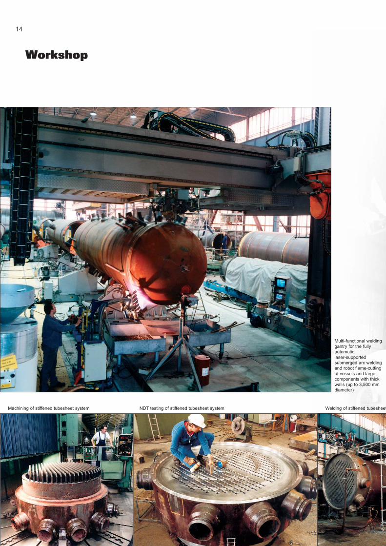
Workshop
14
Multi-functional welding
gantry for the fully
automatic,
laser-supported
submerged arc welding
and robot flame-cutting
of vessels and large
components with thick
walls (up to 3,500 mm
diameter)
Machining of stiffened tubesheet system NDT testing of stiffened tubesheet system Welding of stiffened tubesheet
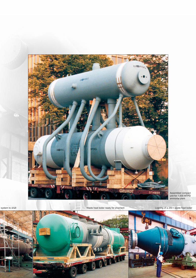
Assembled compact
unit for 1,500 MTPD
ammonia plant
t system to shell Waste heat boiler ready for shipment Loading of a 250 t waste heat boiler
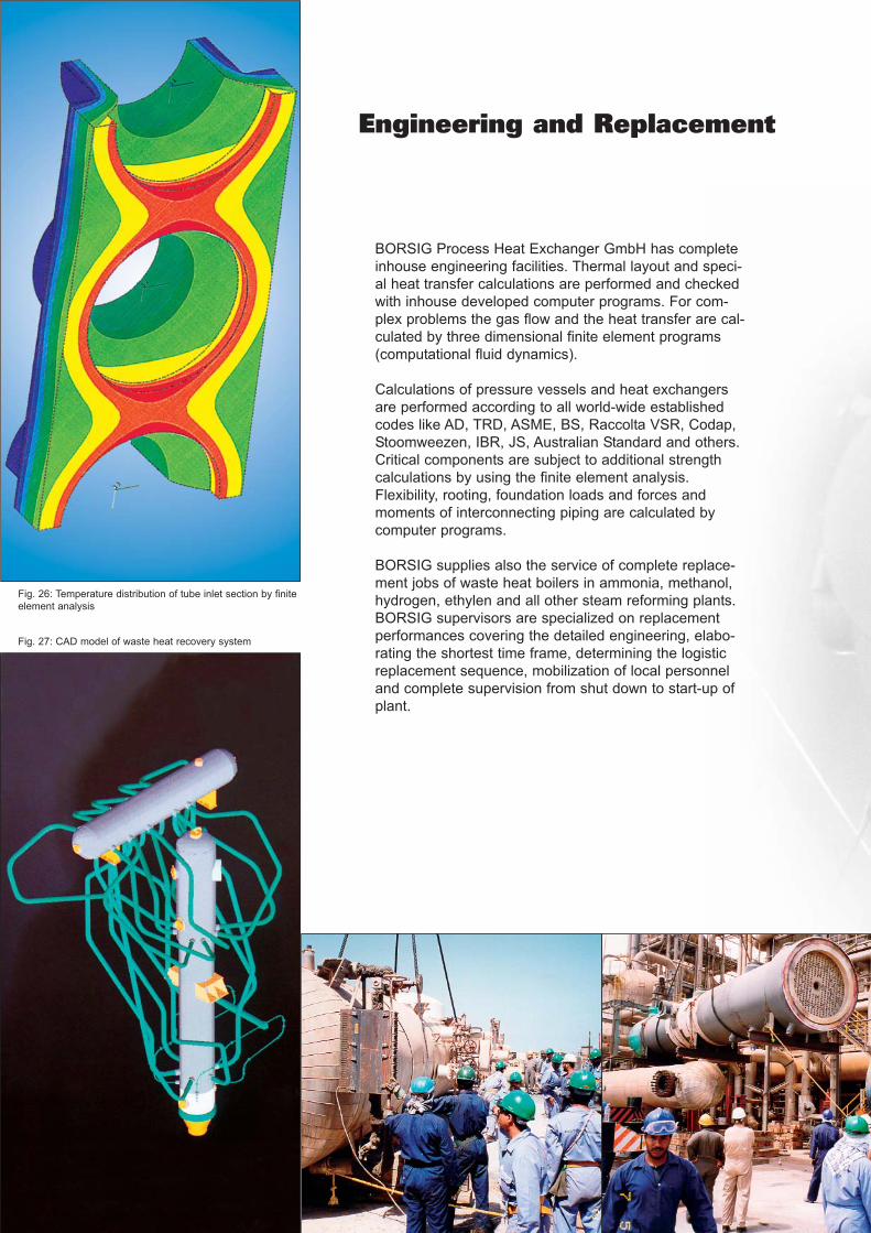
Engineering and Replacement
BORSIG Process Heat Exchanger GmbH has complete
inhouse engineering facilities. Thermal layout and speci-
al heat transfer calculations are performed and checked
with inhouse developed computer programs. For com-
plex problems the gas flow and the heat transfer are cal-
culated by three dimensional finite element programs
(computational fluid dynamics).
Calculations of pressure vessels and heat exchangers
are performed according to all world-wide established
codes like AD, TRD, ASME, BS, Raccolta VSR, Codap,
Stoomweezen, IBR, JS, Australian Standard and others.
Critical components are subject to additional strength
calculations by using the finite element analysis.
Flexibility, rooting, foundation loads and forces and
moments of interconnecting piping are calculated by
computer programs.
BORSIG supplies also the service of complete replace-
ment jobs of waste heat boilers in ammonia, methanol,
hydrogen, ethylen and all other steam reforming plants.
BORSIG supervisors are specialized on replacement
performances covering the detailed engineering, elabo-
rating the shortest time frame, determining the logistic
replacement sequence, mobilization of local personnel
and complete supervision from shut down to start-up of
plant.
Fig. 26: Temperature distribution of tube inlet section by finite
element analysis
Fig. 27: CAD model of waste heat recovery system
BORSIG Process Heat Exchanger GmbH with its manufacturing methods, workshop facilities
and equipment complies fully with the latest state-of-the-art. The high-tech welding technology
is our core competence:
- laser controlled narrow gap SAW welding system,
- robot welding technology for GMAW welding for high pressure vessels,
- TIG-hot wire welding, also on ball valve surfaces,
- mechanical tube to tubesheet welding,
- qualified manufacturing of all steel and nickel-based alloys.
Quality assurance and control activities are independent of the manufacturing process or pro-
duct lines and guarantee that machined and handled materials, components, assemblies, pro-
ducts and service operations are executed in accordance with all specified requirements.
Quality assurance surveils adherence to national and international specifications, statutory and
contract provisions as well as the directives, standards and regulations stipulated by BORSIG.
BORSIG Process Heat Exchanger certification comprise
DIN EN ISO 9001:2000, SCC, ASME U, U2 and S, SQL PR China, Environmental
Management System DIN EN ISO 14001, EMAS II, etc..
In 2003 BORSIG Process Heat Exchanger GmbH has introduced the Integrally Management
System (IMS) comprising of quality, works safety and environmental management systems.
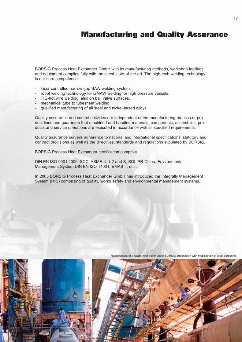
Manufacturing and Quality Assurance
Replacement of a waste heat boiler under BORSIG supervision with mobilization of local personnel.
17
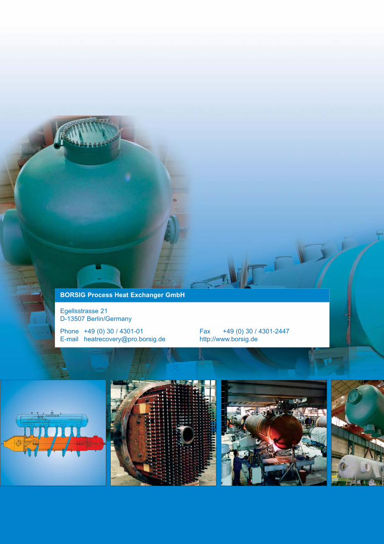
BORSIG Process Heat Exchanger GmbH
Egellsstrasse 21
D-13507 Berlin/Germany
Phone +49 (0) 30 / 4301-01 Fax +49 (0) 30 / 4301-2447
E-mail [email protected] http://www.borsig.de