Process Gas Equipment Ne€¦ · DTube stub)Face seal DTube stub)Face seal DTube stub Connection...
173
Process Gas Equipment Regulators Diaphragm Valves Check Valves Vacuum Generators Flow Switches CAT.ES100-88A New New
Transcript of Process Gas Equipment Ne€¦ · DTube stub)Face seal DTube stub)Face seal DTube stub Connection...

Process Gas EquipmentRegulatorsDiaphragm ValvesCheck ValvesVacuum GeneratorsFlow Switches
CAT.ES100-88A
NewNew

For ultra high purity (UHP)
RegulatorsFor ultra high purity (UHP)
For UHP gas delivery in semiconductor and other clean industries.
Series APSeries AP
Series SLSeries SL
Series AZSeries AZ
AP9000
AP2700
AP1700
AP1600/AP1900
AP500
AP1000/AP1100/AP1500
SL5400/SL5800
SL5200
AP1200
AP1400T
AZ1200/AZ1300/AZ1400T
SL5500
P.2 to 23
P.24 to 31
P.32 to 45
Series BPSeries BP
BP1000 Welded
P.68, 69AZ1000/AZ1100/AZ1500
AZ9200
Forward 1

Series KTSeries KTP.60 to 65
Series AK PASeries AK PAP.86 to 93
For high pressure applications
Regulators
For high pressure applicationsFor air operated applicationsFor air operated applications
AK10PA/AK15PA AK12PA/AK14PAT KT10 KT10 Welded connection KT12
Series AKSeries AKBack Pressure Regulator
Series BPSeries BP
BP1000AK1000/AK1500
AK1700AK9200
AK1200/AK1300/AK1400T
P.46 to 59 P.66, 67
For general applicationsFor general applicationsFor wide variety of applications from semiconductor to general.
For air operated applicationsFor air operated applicationsFor air operated applications
Series AP PASeries AP PAP.70 to 77
Series AZ PASeries AZ PAP.78 to 85
AP10PA/AP15PA AP12PA/AP14PAT AZ10PA/AZ15PA AZ12PA/AZ14PAT
Forward 2

Air operated type
Series APSeries APManually operated type
Series APSeries AP
AP3000/AP3200
AP3130
AP3700
AP3550/AP4550AP3540/AP4540
AP3571/AP4571
AP3100
AP3125
AP3800
AP3900
AP3150AP3600/AP4600/AP3260
AP3625/AP4625
AP3657/AP4657
AP3650/AP4650
Series AP64Series AP64 Series AP7,70/71/72Series AP7,70/71/72 Series AP74/74BSeries AP74/74B
AP64
AP70
AP7
AP74B
AP74AP71
AP72
Technical Data/Glossary of Terms ····································································· P.143, 144
P.100 to 113
P.128, 129 P.130 to 135 P.136 to 139
P.114 to 123
Diaphragm Valves
Check Valve Vacuum Generators Flow Switches
For ultra high purity (UHP)For ultra high purity (UHP)For UHP gas delivery in semiconductor and other clean industries.
Forward 3

Series Features
1) Optional finish not available on all AZ series.
Application
Body material
EP
Surface finishin. ( m)
Connectiontype
Connection
Fitting
Cleanroom Assembly
N2 Testing
Helium Testing
Ultra High Purity (UHP)
316L SSSecondary remelt
Electropolish + Passivation
RaRa max
Welded
Face sealTube stub weld
Threaded
NPTCompression
316L SS316 SSBrass
General applications
Ra32 in. (0.8 m)15 in. (0.4 m)
10 in. (0.25 m)7 in. (0.18 m)5 in. (0.13 m)
10 in. (0.25 m)25 in. (0.62 m) 1)
Series AP Series AZ Series AK
Standard Selectable by model or option
Forward 4

AP1000
AP1100
AP1500
SL5500
AP1600
AP1900
SL5400
SL5800
AP1400T
AP1200
AP500
SL5200
AP1700
AP2700
4) 300
3500
3500
3500
1000
300
23003000
15.920.7
2300 15.9
17003000
11.720.7
1700 11.7
150
150
3500
3500
2.1
24.1
24.1
24.1
6.9
2.1
300 2.1
1.0
1.0
24.1
24.1
316L VAR
316L VAR
316L VAR
316L VAR
316L VAR
316L VAR
316L VAR
316L VAR
316L VAR
316L VAR
316L VAR
316L VAR
316L VAR
316L VAR
Application Construction Material Max. inlet pressureDistribution
(Point of use)Source
(Cylinder)Tied
diaphragm Springless Body 1) Hastelloy®
Internal psig (MPa)Series
Sin
gle
sta
ge
Sin
gle
sta
ge
(co
mp
act)
Tw
o s
tag
e
1) 316L VAR : 316L SS secondary remelt 316L : 316L SS2) In accordance with SEMI F32.3) At 150 psig (1.0 MPa) inlet pressure. Figure varies depending on gas and operating pressures.4) For low vapor pressure gases.
Hastelloy® is a registered trademark of Haynes International.
Regulator Series AP/SLRegulator Series AP/SL
300 2.1
800
250
5.5
1.7
3500 24.1
100 0.7
3500 24.1
AP9100
AP9000
AP9115
11.71700316L
316L
Forward 5

SMC does not sell products in Japan that are METI certified.
1 to 302 to 602 to 1003 to 120
1 to 302 to 602 to 1005 to 150
1 to 100.007 to 0.20.014 to 0.40.014 to 0.70.034 to 1.0
0.007 to 0.07
0.007 to 0.20.014 to 0.40.014 to 0.70.034 to 1.0
0.007 to 0.20.007 to 0.40.014 to 0.70.007 to 0.070.007 to 0.20.014 to 0.40.014 to 0.70.007 to 0.070.007 to 0.20.014 to 0.40.014 to 0.70.034 to 1.0
0.007 to 0.20.007 to 0.40.014 to 0.7
0.007 to 0.20.007 to 0.40.014 to 0.7
0.007 to 0.20.014 to 0.40.014 to 0.70.034 to 1.00.007 to 0.20.014 to 0.40.014 to 0.70.034 to 1.0
0.034 to 0.7Preset to 2.1
0.034 to 0.7
0.034 to 1.0
0.0034 to 0.070.0034 to 0.20.007 to 0.40.007 to 0.7
0.0034 to 0.070.0034 to 0.20.007 to 0.40.007 to 0.70.007 to 0.20.014 to 0.40.014 to 0.7
-88 kPa to 0.07 MPa
1 to 302 to 602 to 1005 to 150
100mmHg abs. to 30psig -88kPa to 0.2MPa
100mmHg abs. to 10psig -88kPa to 0.07MPa
100mmHg abs. to 10psig -88kPa to 0.07MPa
1 to 301 to 602 to 1001 to 101 to 302 to 602 to 1001 to 101 to 302 to 602 to 1005 to 150
1 to 301 to 602 to 100
1 to 301 to 602 to 100
1 to 302 to 60
100mmHg abs. to 30psig -88kPa to 0.2MPa
2 to 1005 to 1501 to 302 to 602 to 1005 to 150
5 to 100Preset to 300
5 to 100
5 to 150
0.5 to 100.5 to 301 to 601 to 100
0.5 to 100.5 to 301 to 601 to 1001 to 302 to 602 to 100
100 mmHgabsoluteto 10 psig
0.007 to 0.20.014 to 0.40.014 to 0.70.021 to 0.8
Standard Selectable by model or optionMay be selected for source applications of inert gases, though tied diaphragm is recommended.
Outlet pressure
psig (MPa)
0.130.16
100150 (HF opt.)
0.23
0.4
0.45
120
200
400
0.651.1
8001000 (HF opt.)1500 (FC opt.)
0.060.1
1530 (HF opt.)
0.070.15
30130 (HF opt.)
0.05
0.105
3.0
4.0
2000
5000
0.090.15
30120 (HF opt.)
0.05
0.09
0.09
0.13
0.5
30
30
100
Sub-atmospheric(Absolute)
Cv 2)
30
150
Flow, N2 3)
slpm
1/43/8
1/43/8
1/4
1/43/8
1/43/8
1/43/8
1/23/41
1/23/41
1/43/81/23/4
1/43/81/2
1/43/81/2
1/43/81/2
1/43/81/2
1/43/8
1/43/8
1/43/8
Connectionsizeinch
Welded
Welded
Welded
Face sealTube stub
Face sealTube stub
Face sealTube stub
Connection type
Connection FittingsPage
P.4
P.16
P.6
P.26
P.8
P.10
P.28
P.30
P.12
P.14
P.22
P.2
P.24
P.18
P.20
Forward 6
AZAK
KTBP
Diap
hrag
m V
alve
sCh
eck
Valv
esVa
cuum
Gen
erat
ors
Flow
Sw
itche
sTe
chni
cal D
ata/
Glos
sary
of Te
rms
Prec
autio
nsSL
APRe
com
men
datio
nsRe
gula
tors

AZ1000
AZ1100
AZ1500
AZ1400T
AZ1300
AZ1200
AZ9200
300
3500
300 2.1
300 2.1
23003000
15.920.7
2300 15.9300 2.1
17003000
11.720.7
1700 11.7
2.1
24.1
316L
Application Construction Material Max. inlet pressureDistribution
(Point of use)Source
(Cylinder)Tied
diaphragm Springless Body 1) Hastelloy®
Internal psig (MPa)Series
Sin
gle
sta
ge
1) 316L : 316L SS 316 : 316 SS B : Brass2) In accordance with SEMI F32.3) At 150 psig (1.0 MPa) inlet pressure. Figure varies depending on gas and operating pressures.4) For low vapor pressure gases.
Hastelloy® is a registered trademark of Haynes International.
AK1000
AK1500
AK1400T
AK1300
AK1200
AK9200
AK1700
3500
3500
300 2.1
3500 24.1
300 2.1
23003000
316B
316B
15.920.7
2300 15.9300 2.1
17003000
11.720.7
1700 11.7
24.1
24.1
Application Construction Material Max. inlet pressureDistribution
(Point of use)Source
(Cylinder)Tied
diaphragm Springless Body 1) Hastelloy®
Internal psig (MPa)Series
Sin
gle
sta
ge
Tw
ost
age
Regulator Series AZRegulator Series AZ
Regulator Series AKRegulator Series AK
300 2.1
3500 24.1
4)
00
300 2.1
Forward 7

SMC does not sell products in Japan that are METI certified.
1 to 101 to 302 to 602 to 1005 to 150
0.007 to 0.070.007 to 0.20.014 to 0.40.014 to 0.70.034 to 1.0
0.007 to 0.20.014 to 0.40.014 to 0.70.034 to 1.0
0.007 to 0.20.014 to 0.40.014 to 0.70.034 to 1.00.007 to 0.20.014 to 0.40.014 to 0.70.034 to 1.00.007 to 0.20.014 to 0.40.014 to 0.70.034 to 1.00.007 to 0.20.014 to 0.40.014 to 0.70.034 to 1.0
-88 kPa to 0.07 MPa
1 to 302 to 602 to 1005 to 150
1 to 302 to 60
-88kPa to 0.2MPa100mmHg abs. to 30psig
2 to 1005 to 1501 to 302 to 602 to 1005 to 1501 to 302 to 602 to 1005 to 1501 to 302 to 602 to 1005 to 150
100 mmHgabsoluteto 10 psig
Standard Selectable by model or optionMay be selected for source applications of inert gases, though tied diaphragm is recommended.
Outlet pressure
psig (MPa)
0.651.1
8001000 (HF opt.)1500 (FC opt.)
1.6 2000
0.090.15
0.05
0.09
30120 (HF opt.)
0.45
1.1
0.5
30
400
1000
Sub-atmospheric(Absolute)
Cv 2) Flow, N2 3)
slpm
1/43/8
1/43/81/21/43/81/2
3/41
1/43/81/2
1/43/8
1/43/8
Connectionsizeinch
Welded Face sealTube stub
Connection type
Connection FittingsPage
0.5 to 101 to 302 to 602 to 1005 to 1505 to 2005 to 30010 to 500
0.007 to 0.070.007 to 0.20.014 to 0.40.014 to 0.70.034 to 1.00.034 to 1.40.034 to 2.10.07 to 3.4
0.007 to 0.20.014 to 0.40.014 to 0.70.034 to 1.0
0.007 to 0.20.014 to 0.40.014 to 0.70.034 to 1.00.007 to 0.20.014 to 0.40.014 to 0.70.034 to 1.00.007 to 0.20.014 to 0.40.014 to 0.70.034 to 1.0
0.007 to 0.20.014 to 0.40.014 to 0.70.034 to 1.4
1 to 302 to 602 to 1005 to 150
1 to 302 to 60
100mmHg abs. to 30psig -88kPa to 0.2MPa
2 to 1005 to 1501 to 302 to 602 to 1005 to 1501 to 302 to 602 to 1005 to 150
1 to 302 to 602 to 1005 to 200
Outlet pressure
psig (MPa)
0.651.1
8001000 (HF opt.)1500 (FC opt.)
0.05 30
0.090.15
30120 (HF opt.)
0.09
0.45
1.1
30
400
1000
Sub-atmospheric(Absolute)
Cv 2) Flow, N2 3)
slpm
1/43/8
1/43/81/2
1/43/8
1/43/81/2
1/43/81/2
1/43/8
Connectionsizeinch
Threaded NPTCompression
Threaded
0.007 to 0.20.014 to 0.40.014 to 0.70.034 to 1.0
1 to 302 to 602 to 1005 to 150
1.6 2000 3/4
NPTCompression
Connection type
Connection FittingsPage
P.32
P.38
P.40
P.42
P.36
P.46
P.48
P.50
P.52
P.54
P.56
P.58
P.44
P.34
Forward 8
KTBP
Diap
hrag
m V
alve
sCh
eck
Valv
esVa
cuum
Gen
erat
ors
Flow
Sw
itche
sTe
chni
cal D
ata/
Glos
sary
of Te
rms
Prec
autio
nsSL
APRe
com
men
datio
nsAZ
Regu
lato
rsAK

AP10PA
AP15PA
AP14PAT
AP12PA
AZ10PA
AZ15PA
AZ14PAT
AZ12PA
AK10PA
AK15PA
AK14PAT
AK12PA
3500
3500
3500
3500
24.1
24.1
3500
3500
23003000
15.920.7
23003000
15.920.7
23003000
15.920.7
17003000
11.720.7
17003000
11.720.7
17003000
11.720.7
24.1
24.1
24.1
24.1
316L VAR
316L
316B
Application Construction Material Max. inlet pressureDistribution
(Point of use)Source
(Cylinder)Tied
diaphragm Springless Body 1) Hastelloy®
Internal psig (MPa)Series
Sin
gle
sta
ge
1) 316L VAR : 316L SS secondary remelt 316L : 316L SS2) In accordance with SEMI F32.3) At 150 psig (1.0 MPa) inlet pressure. Figure varies depending on gas and operating pressures.
Hastelloy® is a registered trademark of Haynes International.
Air Operated Regulator Series AP/AZ/AKAir Operated Regulator Series AP/AZ/AK
A
PA
1666LL6 SS seseccoondary rreemmm166LL6 SS seseccoondary rremm
PA
PAT
PA
PA
(P
A
Forward 9

7 to 150
7 to 150
7 to 150
7 to 150
7 to 150
7 to 150
7 to 150
7 to 150
7 to 150
7 to 150
7 to 150
7 to 150
0.05 to 1.0
0.05 to 1.0
0.05 to 1.0
0.05 to 1.0
0.05 to 1.0
0.05 to 1.0
0.05 to 1.0
0.05 to 1.0
0.05 to 1.0
0.05 to 1.0
0.05 to 1.0
0.05 to 1.0
Outlet pressure
psig (MPa)
0.09
0.45
30
400
0.09
0.45
30
400
0.651.1
8001000 (HF opt.)
0.090.15
0.651.1
8001000 (HF opt.)
0.651.1
8001000 (HF opt.)
0.090.15
30120 (HF opt.)
0.090.15
30120 (HF opt.)
30120 (HF opt.)
0.09
0.45
30
400
Sub-atmospheric(Absolute)
Cv 2)
1/43/8
1/43/8
1/43/81/23/4
1/43/81/2
1/43/8
1/43/8
1/43/8
1/43/81/2
1/43/81/23/4
1/43/81/23/4
1/43/81/2
1/43/8
Welded
Welded
Threaded
Face sealTube stub
Face sealTube stub
NPTCompression
Connection type
ConnectionFlow, N2 3)
slpm
Connectionsizeinch Fittings
Page
Standard Selectable by model or optionMay be selected for source applications of inert gases, though tied diaphragm is recommended.
P.70
P.72
P.74
P.76
P.78
P.80
P.82
P.84
P.86
P.88
P.90
P.92
SMC does not sell products in Japan that are METI certified. Forward 10
KTBP
Diap
hrag
m V
alve
sCh
eck
Valv
esVa
cuum
Gen
erat
ors
Flow
Sw
itche
sTe
chni
cal D
ata/
Glos
sary
of Te
rms
Prec
autio
nsSL
APRe
com
men
datio
nsRe
gula
tors
AZAK

S
B
316L
S
B
10000
6000
4000
6000
5000
69
41.4
27.6
41.4
34.5
5 to 5005 to 800
10 to 150015 to 250025 to 400050 to 6000
100 to 10000
0.034 to 3.40.034 to 5.50.07 to 10.30.1 to 17.20.17 to 27.60.34 to 41.4
0.7 to 69
5 to 5005 to 800
10 to 150015 to 250025 to 400050 to 6000
0.034 to 3.40.034 to 5.50.07 to 10.30.1 to 17.20.17 to 27.60.34 to 41.4
5 to 5005 to 800
10 to 150015 to 250025 to 4000
0.034 to 3.40.034 to 5.50.07 to 10.30.1 to 17.20.17 to 27.6
5 to 1205 to 3005 to 600
10 to 100015 to 150025 to 2500
0.034 to 0.80.034 to 2.10.034 to 4.10.07 to 6.90.1 to 10.30.17 to 17.2
Max. inlet pressure Outlet pressure
psig (MPa) psig (MPa)Series
Series
Bodymaterial 1)
KT10
KT12
316L VAR
316B
1/4
1/43/8
0.3
0.0034 to 0.070.007 to 0.20.014 to 0.40.034 to 0.70.1 to 1.40.1 to 2.1
0.5 to 101 to 302 to 605 to 10015 to 20015 to 300
Operating pressureCv 2)
psig (MPa)
Connectionsizeinch
Bodymaterial 1)
BP1000
1) 316L VAR : 316L SS secondary remelt 316L : 316L SS 316 : 316 SS S : 300 SS series B : Brass2) In accordance with SEMI F32.
High Pressure Regulator Series KTHigh Pressure Regulator Series KT
Back Pressure Regulator Series BPBack Pressure Regulator Series BP
Pressure Gauges (For UHP and general applications) P.94
Forward 11

SMC does not sell products in Japan that are METI certified.
1/4
1/23/4
Threaded
Welded
Threaded
NPT
Face seal
NPT
0.060.12
0.82.0
Cv 2)Connection type
PageConnection
sizeinch Connection Fittings
Threaded
Welded
NPTCompression
Face sealTube stub
Connection typePage
Connection Fittings
Standard Selectable by model or option
P.60
P.62
P.64
P.66
P.68
Forward 12
Diap
hrag
m V
alve
sCh
eck
Valv
esVa
cuum
Gen
erat
ors
Flow
Sw
itche
sTe
chni
cal D
ata/
Glos
sary
of Te
rms
Prec
autio
nsSL
APRe
com
men
datio
nsRe
gula
tors
AZAK
KTBP

AP3540
AP3550
AP3580
AP3000
AP4540
AP4550
AP4580
AP3113
AP3130
AP3700
AP3708
316L VAR
Application Status Bodymaterial 1)Distribution
(Point of use)Source
(Cylinder) N.C. N.O.Series
Air
op
erat
ed
AP3571
AP4571
316L VAR
Application Status Bodymaterial 1)Distribution
(Point of use)Source
(Cylinder) N.C. N.O.Series
Air o
pera
ted
Two
step
mod
eDiaphragm Valves (Air operated)Diaphragm Valves (Air operated)
Diaphragm Valves (Two step mode)Diaphragm Valves (Two step mode)
1) 316L VAR : 316L SS secondary remelt2) In accordance with SEMI F32.
Forward 13

125
250
250
3000
125
250
250
1300
3000
250
250
0.9
1.7
1.7
20.7
0.9
1.7
1.7
9.0
20.7
1.7
1.7
Max. operating pressure Connectionsizeinchpsig
LOTO
0.5
0.5
0.5
1.0
0.7
2.8
2.8
0.230.28
0.29
0.29
0.29
Cv 2)
1/43/8
1/43/8
1/43/8
1/43/81/23/4
3/81/23/4
WeldedFace sealTube stub
Connection type
Connection FittingPage
(MPa)
Standard Selectable by model or optionSource applications for maximum source pressure of 250 psig (1.7 MPa) or less.
125
125
0.9
0.9
Max. operating pressure Connectionsizeinchpsig
LOTO
0.29
0.5
Cv 2)
1/43/8
Face sealTube weld
Connection type
Connection
Welded
FittingPage
(MPa)
P.100
P.104
P.102
P.106
P.108
P.110
SMC does not sell products in Japan that are METI certified. Forward 14
AZAK
KTBP
Diap
hrag
m V
alve
sCh
eck
Valv
esVa
cuum
Gen
erat
ors
Flow
Sw
itche
sTe
chni
cal D
ata/
Glos
sary
of Te
rms
Prec
autio
nsSL
APRe
com
men
datio
nsRe
gula
tors

AP3600
AP3625
AP3650
AP3657
AP4600
AP4625
AP4650
AP4657
AP3100
AP3125
AP3150
AP3157
AP3800
AP3900
Multi turn round knob
1/4 turn lever knob
1/4 turn indicating round knob
Pull twist round knob
Multi turn round knob
1/4 trun lever knob
1/4 turn indicating round knob
Pull twist round knob
Multi turn round knob
1/4 turn lever knob
1/4 turn indicating round knob
Pull twist round knob
Round knob
Pull twist round knob
316L VAR
ApplicationKnob Body
material 1)Distribution(Point of use)
Source (Cylinder)
Series
Man
ual
AP3200
AP3260
Air
oper
ated
Manu
al 316L VAR
ApplicationStatus or Knob Body
material 1)Distribution(Point of use)
Source(Cylinder)
N.C.
Multi turn round knob
Series
1) 316L VAR : 316L SS secondary remelt 2) In accordance with SEMI F32.
Diaphragm Valves (Manual)Diaphragm Valves (Manual)
Diaphragm Valves (Metal seated)Diaphragm Valves (Metal seated)
Option (LOTO, Operational Safety Device) P.124 Porting Guide P.125
Forward 15

20.7
1.7
20.7
20.7
9.0
9.0
1.7
0.29
0.5
1.0
1.0
1.0
2.8
3000
250
3000
3000
1300
1300
250
Max. operating pressure Connectionsizeinchpsig
LOTO
0.71.3
Cv 2)
1/43/8
1/43/8
1/43/81/23/4
3/81/23/4
WeldedFace sealTube stub
Connection type
Connection FittingPage
(MPa)
125
125
0.9
0.9
Maximum inlet pressure Connectionsizeinchpsig
LOTO
0.27
0.27
Cv 2)
1/43/8
Face sealTube weld
Connections
Connection
Welded
FittingPage
MPa
P.114
P.116
P.118
P.120
P.112
P.122
Standard Selectable by model or optionSource applications for maximum source pressure of 250 psig (1.7 MPa) or less.
SMC does not sell products in Japan that are METI certified. Forward 16
AZAK
KTBP
Diap
hrag
m V
alve
sCh
eck
Valv
esVa
cuum
Gen
erat
ors
Flow
Sw
itche
sTe
chni
cal D
ata/
Glos
sary
of Te
rms
Prec
autio
nsSL
APRe
com
men
datio
nsRe
gula
tors

AP64 3500316L VAR 24.1
Bodymaterial
1)
Max. operatingpressure
psigCv 2)
psid
3
(MPa)
0.023
Crackingpressure
0.4 max
Connectionsizeinch
1/4 Face sealTube stub
Connection type
Connection
Welded
FittingPage
(MPa)Series
Standard Selectable by model or option
AP7
AP70
AP71
AP72
-26 (100)
-26 (100)
-26 (100)
-26 (100)
316L
316L
316L
316L VAR
-88
-88
-88
-88
Bodymaterial
1)
Max. vacuumpressure
in.Hg(Torr)
Constantbleedpsid
—
—
3
3
(MPa)
—
—
0.023
0.023
Check valvecracking pressureModules
3)
Connectionsizeinch
1/43/8
1/43/8
1/43/8
1/43/8
Face sealTube stub
Connection type
Connection
Welded
FittingPage
(kPa)Series
3500
3500
2400
24.1
24.1
16.3
1/4
1/2
3/4
Bodymaterial
1)
Max. operatingpressure
psig
25102550100
225350500950
110016502600
Flow, at 100 psig (0.69 MPa) N2
slpm
Connectionsizeinch
Face sealTube stub
Connections
Connection
Welded
FittingPage
MPaSeries
AP74
AP74B
316L VAR
316L
1) 316L VAR : 316L SS secondary remelt 316L : 316L SS2) In accordance with SEMI F32.3) Monoblock vacuum generator, N2 supply valve and check valve
P.128
P.130
P.130
P.132
P.134
P.136
P.138
Check ValveCheck Valve
Vacuum GeneratorVacuum Generator
Flow SwitchFlow Switch
SMC does not sell products in Japan that are METI certified.
Regulator and Valve Selection Guide ··· Forward 19 to 25Technical Data/Glossary of Terms ········ P.143, 144
Forward 17

Regulators P.1
Diaphragm Valves P.99
Check Valves P.127
Vacuum Generators P.127
Flow Switches P.127
Forward 18

Regulator and Valve Selection Guide
Valve and Regulator Recommendationsfor source and distribution application
This guide is a reference guide to help customers determine an appropriate AP Tech valve and regulator to be used in process gas systems. Before selecting a product, please make sure to read through this guide. For information and specifications related to the specific model, please refer to the catalog data sheet.
Source valves are those on the upstream side of the pressure regulator in the source gas cabinet or bulk delivery system.
Distribution valves are those on the downstream side of the pressure regulator in the source gas cabinet or bulk delivery system and used anywhere downstream of the regulator (s) for cylinder applications at point of use (POU) in valve manifold boxes (VMBs) and process tools.
Source regulators are those used in the source gas cabinet or bulk delivery system.
Distribution regulators are those used at point of use (POU) in valve manifold boxes (VMBs) and process tools. Recommendations are based on typical usage. Operating practices at a specific facility may require a different component selection.
It is assumed that non-liquefied gas cylinders are switched over to a new cylinder when the pressure drops to 150 to 250 psig (1.0 to 1.7 MPa). Therefore, maximum recommended flow rates for source regulators and source valves assume 150 to 250 psig (1.0 to 1.7 MPa) inlet pressure for this gas.
It is assumed that the cylinder pressure for liquefied gas systems is maintained at or above the vapor pressure at 16 C. It is assumed that cylinders are switched over before the liquid is all vaporized into gas. Therefore, maximum recommended flow rates for source regulators are based on 16 C vapor pressure at the regulator inlet for these gases.
Absolute or very low positive pressure delivery bear close scrutiny. The AP1402TA delivers both sub-atmospheric and positive pressure (30 psig) equally well, whereas the AP1101 is strictly intended for sub-atmospheric pressure delivery (10 psig or less). If low flow and very low positive pressure delivery is desired, the AP1001 should be selected instead of the AP1101. The alternative is to select the AP1402TA which provides more flow capacity and the ability to delivery sub-atmospheric and positive pressure.
The SHP option is for certain point of use applications in lieu of the SH option. The SHP designation provides
Hastelloy® C-22 internals comprised of the poppet and diaphragm, whereas the SH option includes the nozzle.
If a source regulator is listed as and , it means two stage regulation is required. The two regulators are in series with listed as the first stage and listed as the second stage.
Valve recommendations are based on typical cylinder pressures and delivery line pressures. Pressure drop across valves at low pressures may be excessive and required a different valve selection.
Valve recommendations are for the process line isolation. Purge and vent valves are not addressed in this document but generally an AP3000, AP3650, or AP3540 valve will provide sufficient flow capability. The valve series recommended were purposely limited for the sake of brevity. The model number indicates the basic size and rating. For example, manually operated valves are noted as AP3650 but an AP3600 or AP3625 would also be appropriate and equivalent selections.
Vespel® seats are recommended for nitrous oxide (N2O) and for souce applications for carbon dioxide (CO2) with either continuous flow demand or flow rates in excess of 100 slpm.
Heating may be required in the source manifold for some gases even when not stated due to duration of flow, ambient conditions, etc. When heating is recommended, appropriate heating method shall be selected depending on gas type. In general, the gas should be heated upstream of the pressure regulator.
Distribution line pressure is assumed to be 60 psig (0.4 MPa) minimum or typical source pressure whichever is less. If the actual line pressure is higher, then higher flow rates than listed in this guideline can be obtained.
The guide's general recommendations are based upon typical appications from material point of view. Some series are not available depending on the regulations in different countries so the selection should be made complying with the regulations in the countries where the product will be used.In Japan since using compression fittings for toxic gas is prohibited, AP/AZ series should be used for toxic gas. The proper regulator and valve selection can be significantly affected by parameters such as system design, flow duration, frequency of use, ambient conditions and outlet pressure. Please consult SMC for a specific recommendation beyond the scope of this document or if any doubt exists. It is important to understand that one may follow this guide’s recommendation, yet have a failure due to a parameter specific to the given application, as noted. Restated, one may achieve higher or lower flow capacities than stipulated in this guide due to the parameters and conditions of a specific application and system design.
Precautions for selection
CautionSince the product specified here is used under various operating conditions, its compatibility with fluid and specific equipment must be decided by the person who designs the equipment or decided its specifications based on necessary analysis and test results.The expected performance and safety assurance of the equipment will be the responsibility of the person who has determined its compatibility with the product regardless of any recommendation.Proper installation, operation and maintenance are also required to assure safe, trouble free performance.Forward 19

Recommended Model Selection Table
230
280
185
225
550475
250
450
1000
200
350
1000
Application Valve Regulator
Source applications Distribution applications Source applications Distribution applications
Maximumflow
(slpm)
Maximumflow
(slpm)
Maximumflow
(slpm)
Maximumflow
(slpm)Recommendation RecommendationRecommendationRecommendation
Process Gas
AP3000AP3650AP3002AP3650
AP3000AP3650AP3002AP3650AP3100AP3130AP3125AP3540AP3650AP4540AP4650AP3113AP3125
AP3000AP3650AP3002AP3650AP3130AP3125
25
45
400
90
160
890
100
225
1000
80
150
800
AP3540AP3650AP4540AP4650AP3700AP3800AP3540AP3650AP4540AP4650AP3800AP3700AP3800AP3540AP3650AP4540AP4650AP3700AP3800
AP3540AP3650AP4540AP4650AP3700AP3800
35075
30100200800
55075
400600
1100
10100300
1500
AP/AZ/AK1500SAP/AZ/AK1400TSAP/AZ/AK1200S
AP/AZ/AK1500SAP1900S
AP/AZ/AK1400TSAP/AZ/AK1200S HR
AP/AZ/AK1500SAP/AZ/AK1400TSAP/AZ/AK1200SAP/AZ/AK1200S
AP/AZ/AK1200S HFAP9100S
AP/AZ/AK1500SAP1900S
AP1900S HFAP/AZ/AK1200S HR
36
5075
95
3050
150400
600
53060
125
250
5001000
102550
100
200
4001000
AP/AZ/AK1000SAP/AZ/AK1000S HFAP/AZ/AK1400TSAP/AZ/AK1200S
AP/AZ/AK1200S HFAZ/AK1300S
AP/AZ/AK1000SAP/AZ/AK1000S HFAP/AZ/AK1400TSAP/AZ/AK1200S
AP/AZ/AK1200S HFAZ/AK1300S
AP/AZ/AK1000SAP/AZ/AK1000S HFAP/AZ/AK1400TSAP/AZ/AK1200S
AP/AZ/AK1200S HFAZ/AK1300S
AP/AZ/AK1200S FCAP9100S
AP/AZ/AK1000SAP/AZ/AK1000S HFAP/AZ/AK1400TSAP/AZ/AK1200S
AP/AZ/AK1200S HFAZ/AK1300S
AP/AZ/AK1200S FCAP9100S
Acetylene
(C2H2)
Air
Ammonia(NH3)
Argon(Ar)
15 psig (0.1MPa) maximum source regulator outlet pressure. denotes heating required to achieve stated flow.
How to read model number listed as recommendation.
Example
Valve
AP3650Regulator
AP/AZ/AK1200 S VS HF AP/AZ1402T S A
For more details, please refer to catalog.
Please read the forward 15 before selecting a product.
SeriesAP/AZ/AK1200: 3 series are recommended (AP1200, AZ1200, AK1200).Valve: Only typical series is shown as recommendation and other models with same specifications (operating pressure, Cv) are also recommended.For example, other than AP3650, AP3600/3625/3657 are also recommended.
MaterialS: Stainless steel body as standard design.SH: Stainless steel body with Hastelloy® internals as it further improves corrosion resistance than S (standard design).Either SH or SHP can be used with AP series regulators and SHP is used with AZ series regulators. (SHP provides Hastelloy® internals comprised of the poppet and diaphragm, whereas SH includes the nozzle.)Material of stainless steel body varies depending on series.
AP series (except AP9000&9100) … 316L SS secondary remeltAZ series and AP9000&9100 … 316L SSAK series … 316 SS
VS: Seat material is made of Vespel®. (Only for specific series)No code: PCTFE as standard design.
Option (Only for specific series)HF: High flowFC: Force compensationHR: High inlet pressure
A: Delivery of sub-atmospheric pressure. (Only for specific series)
Forward 20
AZAK
KTBP
Diap
hrag
m V
alve
sCh
eck
Valv
esVa
cuum
Gen
erat
ors
Flow
Sw
itche
sTe
chni
cal D
ata/
Glos
sary
of Te
rms
Prec
autio
nsSL
APRe
com
men
datio
nsRe
gula
tors

140
240
185
225
20
185
225
115
145
115
145
35
65
500
700
2500
185
225
75
150
300
20
185
225
20
70
85
14
150
14
Application Valve Regulator
Source applications Distribution applications Source applications Distribution applications
Maximumflow
(slpm)
Maximumflow
(slpm)
Maximumflow
(slpm)
Maximumflow
(slpm)Recommendation RecommendationRecommendationRecommendation
Process Gas
AP3540AP3650AP4540AP4650AP3000AP3650AP3002AP3650AP4540AP4650AP3000AP3650AP3002AP3650AP3000AP3650AP3002AP3650AP3000AP3650AP3002AP3650AP3540AP3650AP4540AP4650AP3000AP3650AP3002AP3650AP3113AP3125
AP3000AP3650AP3002AP3650AP3540AP3650AP4540AP4650AP3113AP3125
AP4540AP4650AP3000AP3650AP3002AP3650AP4540AP4650AP3000AP3650AP3002AP3650AP4540AP4650AP3700AP3800AP4540AP4650
55
95
90
160
15
90
160
60
100
60
100
30
60
75
140
750
90
160
50
100
400
15
90
160
20
35
60
7
75
7
AP3540AP3650AP4540AP4650AP3540AP3650AP4540AP4650AP4540AP4650AP3540AP3650AP4540AP4650AP3540AP3650AP4540AP4650AP3540AP3650AP4540AP4650AP3540AP3650AP4540AP4650AP3540AP3650AP4540AP4650AP3700AP3800
AP3540AP3650AP4540AP4650AP3540AP3650AP4540AP4650AP3700AP3800
AP4540AP4650AP3540AP3650AP4540AP4650AP4540AP4650AP3540AP3650AP4540AP4650AP4540AP4650AP3700AP3800AP4540AP4650
540
1550
150
6
1560
525
525
350
375
150
500
1000
51550
35075
200
6
5225
7
35
25
35075
17
AP/AZ/AK1500SAP/AZ/AK1400TS
AP/AZ/AK1500SAP1900S
AP/AZ/AK1400TS
AP/AZ/AK1402TSA
AP/AZ/AK1500SAP/AZ/AK1400TS
AP/AZ/AK1500SAP/AZ/AK1400TS
AP/AZ/AK1500SAP/AZ/AK1400TS
AP/AZ/AK1500SAP/AZ/AK1400TS
AP/AZ/AK1500SAP/AZ/AK1400TS
AP/AZ/AK1200S VS
AP/AZ/AK1500SAP1900S
AP/AZ/AK1400TS
AP/AZ/AK1500SHAP/AZ/AK1400TSAP/AZ/AK1200SH
AP/AZ/AK1200SH HF
AP/AZ/AK1402TSA
AP1700SAP2700S
AP/AZ1402TSA
AP/AZ/AK1500SAP1900S
AP/AZ/AK1400TS
AP/AZ/AK1500SAP/AZ/AK1400TSAP/AZ/AK1200S
AP/AZ/AK1000SAP/AZ/AK1402TSA
520
1550
150
0.46
153060
51025
51025
35
82040
100
160
325800
51550
5153075
125
2500.56
1020
1735
25
35075
17
AP/AZ/AK1000SAP/AZ/AK1000S HF
AP/AZ/AK1000SAP/AZ/AK1000S HFAP/AZ/AK1400TS
AP/AZ/AK1101SHAP/AZ/AK1402TSA
AP/AZ/AK1000SAP/AZ/AK1000S HFAP/AZ/AK1400TS
AP/AZ/AK1000SAP/AZ/AK1000S HFAP/AZ/AK1400TS
AP/AZ/AK1000SAP/AZ/AK1000S HFAP/AZ/AK1400TS
AP/AZ/AK1000SAP/AZ/AK1000S HF
AP/AZ/AK1000SAP/AZ/AK1000S HFAP/AZ/AK1400TSAP/AZ/AK1200S
AP/AZ/AK1200S HFAZ/AK1300S
AP/AZ/AK1200S FCAP9100S
AP/AZ/AK1000SAP/AZ/AK1000S HFAP/AZ/AK1400TS
AP/AZ/AK1000SHAP/AZ/AK1000SH HF
AP/AZ/AK1400TSAP/AZ/AK1200SH
AP/AZ/AK1200SH HFAZ/AK1300S
AP/AZ/AK1200SH FCAP/AZ/AK1101S
AP/AZ/AK1402TSAAP/AZ/AK1000S
AP/AZ/AK1000S HF
AP1001SAP/AZ/AK1402TSA
AP/AZ/AK1000SAP/AZ/AK1000S HFAP/AZ/AK1400TS
AP/AZ/AK1000SAP/AZ/AK1400TSAP/AZ/AK1200S
AP/AZ/AK1000SAP/AZ/AK1402TSA
Carbon Dioxide(CO2)
Carbon Monoxide(CO)
Chlorine(Cl2)
ChlorineTrifluoride(ClF3)
Diborane Mixtures(Nitrogen Balance)
Dichlorosilane(SiH2Cl2)
Dimethylsilane(C2SiH8)
Disilane(Si2H6)
Diethyltelluride(Te(C2H5)2)
AP/AZ/AK1225S VSAP/AZ/AK1200S VS HF
AP9030S VSAP9100S VS
If and are indicated in front of a model number, it means two stage regulation is required. The two regulators are in series with listed as the first stage and listed as the second stage.
Arsine(AsH3)
Arsine Mixtures(Nitrogen Balance)
Boron Trichloride(BCl3)
Boron TrichlorideMix
(Nitrogen Balance)
Boron Trifluoride(BF3)
Boron 11Trifluoride
(11BF3)
Butene-1(C4H8)
denotes heating required to achieve stated flow.Please read the forward 16 regarding how to read model number listed as recommendation.
Please read the forward 15 before selecting a product.
Recommended Model Selection Table
Forward 21

380
485
10
185
225
10
18
185
225
55
15
140
170
110
190
10
200
600
25
115
140
140
175
30
60
60
100
275
Application Valve Regulator
Process Gas
AP3000AP3650AP3002AP3650AP3200AP3000AP3650AP3002AP3650AP3540AP3650AP4540AP4650AP3000AP3650AP3002AP3650AP4540AP4650
AP4540AP4650AP3000AP3650AP3002AP3650AP3540AP3650AP4540AP4650AP3000AP3650AP3002AP3650AP3130AP3125
AP4540AP4650
AP3000AP3650AP3002AP3650AP3000AP3650AP3002AP3650AP4540AP4650
AP4540AP4650
AP3000AP3650AP3002AP3650AP3113AP3125
90
160
10
90
160
4
7
90
160
40
15
40
70
35
65
50
100
500
15
145
250
55
100
25
40
40
80
400
AP3540AP3650AP4540AP4650AP3200AP3540AP3650AP4540AP4650AP3540AP3650AP4540AP4650AP3540AP3650AP4540AP4650AP4540AP4650
AP4540AP4650AP3540AP3650AP4540AP4650AP3540AP3650AP4540AP4650AP3540AP3650AP4540AP4650AP3700AP3800
AP4540AP4650
AP3540AP3650AP4540AP4650AP3540AP3650AP4540AP4650AP4540AP4650
AP4540AP4650
AP3540AP3650AP4540AP4650AP3700AP3800
35075
525
17
102050
350
5
350
350
104080
500
5
1050
35075
7
35075
35075
125
AP/AZ/AK1500SAP/AZ/AK1400TSAP/AZ/AK1200S
AP/AZ/AK1500SHAP/AZ/AK1400TS
AP/AZ/AK1000SAP/AZ/AK1402TSA
AP/AZ/AK1500SAP1900S
AP/AZ/AK1400TS
AP/AZ/AK1500SAP/AZ/AK1400TS
AP/AZ1400TSA
AP/AZ/AK1500SAP/AZ/AK1400TS
AP/AZ/AK1500SAP/AZ/AK1400TS
AP/AZ/AK1500SAP1900S
AP1900S HFAP/AZ/AK1200S HR
AP/AZ/AK1402TSA
AP/AZ/AK1500SAP/AZ/AK1400TS
AP/AZ/AK1500SAP/AZ/AK1400TSAP/AZ/AK1200S
AP/AZ/AK1402TSA
AP/AZ/AK1500SAP/AZ/AK1400TSAP/AZ/AK1200S
AP/AZ/AK1500SAP/AZ/AK1400TSAP/AZ/AK1200S
AP/AZ/AK1200S HF
35
5075
51025
17
102050
35
500.5535
50
35
50
5153060
100
250500
0.5
5102050
36
50750.51735
50753
102550
90
175450
AP/AZ/AK1000SAP/AZ/AK1000S HFAP/AZ/AK1400TSAP/AZ/AK1200S
AP/AZ/AK1000SHAP/AZ/AK1000SH HF
AP/AZ/AK1400TS
AP/AZ/AK1000SAP/AZ/AK1402TSA
AP/AZ/AK1000SAP/AZ/AK1000S HFAP/AZ/AK1400TS
AP/AZ/AK1000SAP/AZ/AK1000S HFAP/AZ/AK1400TS
AP/AZ1101SAP/AZ1402TSAAP/AZ/AK1000S
AP/AZ/AK1000S HFAP/AZ/AK1400TS
AP/AZ/AK1000SAP/AZ/AK1000S HFAP/AZ/AK1400TS
AP/AZ/AK1000SAP/AZ/AK1000S HFAP/AZ/AK1400TSAP/AZ/AK1200S
AP/AZ/AK1200S HFAZ/AK1300
AP/AZ/AK1200S FCAP9100S
AP/AZ1101SAP1001S
AP/AZ/AK1402TSAAP/AZ/AK1000S
AP/AZ/AK1000S HFAP/AZ/AK1400TS
AP/AZ/AK1000SAP/AZ/AK1000S HFAP/AZ/AK1400TSAP/AZ/AK1200SAP/AZ/AK1101SAP/AZ/AK1000S
AP/AZ/AK1402TSAAP/AZ/AK1000S
AP/AZ/AK1000S HFAP/AZ/AK1400TSAP/AZ/AK1200SAP/AZ/AK1000S
AP/AZ/AK1000S HFAP/AZ/AK1400TSAP/AZ/AK1200S
AP/AZ/AK1200S HFAZ/AK1300
AP/AZ/AK1200S FCAP9100S
Halocarbon 13B1(CBrF3)
Halocarbon 14(CF4)
Halocarbon 21(CHCl2F)
Halocarbon 23(CHF3)
Halocarbon 32(CH2F2)
Halocarbon 114(C2Cl2F4)
Halocarbon 115(C2ClF5)
Halocarbon 116(C2F6)
Ethylene(C2H4)
Fluorine(F2)
Fluorine Mixtures(10 %, 3.4 MPa)
(Nitrogen Balance)
Germane(GeH4)
Halocarbon 12(CCl2F2)
Halocarbon 12B2(CBr2F2)
Halocarbon 13(CClF3)
Germane Mixtures(Nitrogen Balance)
Consult Factory Consult Factory
Maximumflow
(slpm)
Maximumflow
(slpm)
Maximumflow
(slpm)
Maximumflow
(slpm)Recommendation RecommendationRecommendationRecommendation
If and are indicated in front of a model number, it means two stage regulation is required. The two regulators are in series with listed as the first stage and listed as the second stage.
denotes heating required to achieve stated flow.Please read the forward 16 regarding how to read model number listed as recommendation.
Please read the forward 15 before selecting a product.
Source applications Distribution applications Source applications Distribution applications
Recommended Model Selection Table
Forward 22
AZAK
KTBP
Diap
hrag
m V
alve
sCh
eck
Valv
esVa
cuum
Gen
erat
ors
Flow
Sw
itche
sTe
chni
cal D
ata/
Glos
sary
of Te
rms
Prec
autio
nsSL
APRe
com
men
datio
nsRe
gula
tors

180
55
350
35
60
25
750
1000
2500
800
1600
3000
155
190
350
500
2000
210
265
20
125
215
185
225
210
260
AP4540AP4650
AP4540AP4650AP3100AP3700AP3800AP3540AP3650AP4540AP4650AP4540AP4650AP3000AP3650AP3002AP3650AP3130AP3125
AP3000AP3650AP3002AP3650AP3130AP3125
AP3000AP3650AP3002AP3650AP3000AP3650AP3002AP3650AP3113AP3125
AP3000AP3650AP3002AP3650AP4540AP4650AP3540AP3650AP4540AP4650AP3000AP3650AP3002AP3650AP3000AP3650AP3002AP3650
70
40
230
20
40
20
250
450
2500
300
600
3000
55
95
75
150
850
105
190
20
55
95
90
160
80
140
AP4540AP4650
AP4540AP4650AP3800AP3700AP3800AP3540AP3650AP4540AP4650AP4540AP4650AP3540AP3650AP4540AP4650AP3700AP3800
AP3540AP3650AP4540AP4650AP3700AP3800
AP3540AP3650AP4540AP4650AP3540AP3650AP4540AP4650AP3700AP3800
AP3540AP3650AP4540AP4650AP4540AP4650AP3540AP3650AP4540AP4650AP3540AP3650AP4540AP4650AP3540AP3650AP4540AP4650
32575
35075
35075
6
125500625
2000
125500625900
1200
13050
290
150
600
2000
102040
5
540
102050
540
AP/AZ/AK1500SAP/AZ/AK1400TSAP/AZ/AK1200S
AP/AZ/AK1500SAP/AZ/AK1400TSAP/AZ/AK1200S
AP/AZ/AK1500SAP/AZ/AK1400TSAP/AZ/AK1200S
AP/AZ/AK1402TSA
AP/AZ/AK1500SAP1900S
AP1900S HFAP/AZ/AK1200S HR
AP/AZ/AK1500SAP1900S
AP1900S HFAP2700S
AP/AZ/AK1200S HR
AP/AZ/AK1500SHAP/AZ/AK1400TSAP/AZ/AK1200SH
AP/AZ/AK1500SHAP/AZ/AK1400TSAP/AZ/AK1200SH
AP/AZ/AK1500SHAP1900SH
AP/AZ/AK1400TS
AP/AZ/AK1402TSA
AP/AZ/AK1500SAP/AZ/AK1400TS
AP/AZ/AK1500SAP1900S
AP/AZ/AK1400TS
AP/AZ/AK1500SAP/AZ/AK1400TS
35
257535
5075
35
507516
65125275625
900
12002500
65125275625
900
12003000
12
30508
204085
160
300800102040
5
52040
102050
51040
AP/AZ/AK1000SAP/AZ/AK1000S HFAP/AZ/AK1400TSAP/AZ/AK1200SAP/AZ/AK1000S
AP/AZ/AK1000S HFAP/AZ/AK1400TSAP/AZ/AK1200S
AP/AZ/AK1000SAP/AZ/AK1000S HFAP/AZ/AK1400TSAP/AZ/AK1200SAP/AZ/AK1101S
AP/AZ/AK1402TSAAP/AZ/AK1000S
AP/AZ/AK1000S HFAP/AZ/AK1400TSAP/AZ/AK1200S
AP/AZ/AK1200S HFAZ/AK1300
AP/AZ/AK1200S FCAP9100S
AP/AZ/AK1000SAP/AZ/AK1000S HFAP/AZ/AK1400TSAP/AZ/AK1200S
AP/AZ/AK1200S HFAZ/AK1300S
AP/AZ/AK1200S FCAP9100S
AP/AZ/AK1000SHAP/AZ/AK1000SH HF
AP/AZ/AK1400TSAP/AZ/AK1200SHAP/AZ/AK1000SH
AP/AZ/AK1000SH HFAP/AZ/AK1400TSAP/AZ/AK1200SH
AP/AZ/AK1200SH HFAZ/AK1300S
AP/AZ/AK1200SH FCAP9100S
AP/AZ/AK1000SHAP/AZ/AK1000SH HF
AP/AZ/AK1400TS
AP/AZ/AK1402TSA
AP/AZ/AK1000SAAP/AZ/AK1000S HF
AP/AZ/AK1400TS
AP/AZ/AK1000SAP/AZ/AK1000S HFAP/AZ/AK1400TS
AP/AZ/AK1000SAP/AZ/AK1000S HFAP/AZ/AK1400TS
Hydrogen(H2)
Hydrogen Bromide(HBr)
Hydrogen Chloride(HCl)
Hydrogen ChlorideMixtures
(Nitrogen Balance)
Hydrogen Fluoride(HF)
Hydrogen Selenide(H2Se)
Hydrogen SelenideMixtures
(Nitrogen Balance)
Hydrogen Sulfide(H2S)
AP1225SHAP1210SH HF
AP9030SAP9110S
Halocarbon 125(C2HF5)
Halocarbon R218(C3F8)
Helium(He)
Halocarbon 134A(C2H2F4)
Halocarbon C318(C4F8)
Application Valve Regulator
Process Gas
Maximumflow
(slpm)
Maximumflow
(slpm)
Maximumflow
(slpm)
Maximumflow
(slpm)Recommendation RecommendationRecommendationRecommendation
If and are indicated in front of a model number, it means two stage regulation is required. The two regulators are in series with listed as the first stage and listed as the second stage.
denotes heating required to achieve stated flow.Please read the forward 16 regarding how to read model number listed as recommendation.
Please read the forward 15 before selecting a product.
Source applications Distribution applications Source applications Distribution applications
Recommended Model Selection Table
Forward 23

105
130
245
295
40
70
60
200
350
400
490
215
260
250
400
1000
75
100
350
310
380
300
500
1500
15
250
400
AP3000AP3650AP3002AP3650AP3000AP3650AP3002AP3650AP3540AP3650AP4540AP4650AP4540AP4650AP3540AP3650AP4540AP4650AP3000AP3650AP3002AP3650AP3000AP3650AP3002AP3650AP3000AP3650AP3002AP3650AP3130AP3125
AP3000AP3650AP3002AP3650AP3130AP3125
AP3000AP3650AP3002AP3650AP3000AP3650AP3002AP3650AP3113AP3125
AP4540AP4650AP3000AP3650AP3002AP3650
50
90
120
210
25
40
45
70
120
120
200
110
190
100
200
1000
60
110
500
75
125
70
140
750
15
75
150
1000
AP3540AP3650AP4540AP4650AP3540AP3650AP4540AP4650AP3540AP3650AP4540AP4650AP4540AP4650AP3540AP3650AP4540AP4650AP3540AP3650AP4540AP4650AP3540AP3650AP4540AP4650AP3540AP3650AP4540AP4650AP3700AP3800
AP3540AP3650AP4540AP4650AP3700AP3800
AP3540AP3650AP4540AP4650AP3540AP3650AP4540AP4650AP3700AP3800
AP4540AP4650AP3540AP3650AP4540AP4650AP3700AP3800
2060
102040
350
1103
5075
550
2040
300
50200250350
1000
560
150
400
1000
35075
360
100150
500
1000
5
1080
1501000
AP/AZ/AK1500SAP/AZ/AK1400TS
AP/AZ/AK1500SAP1900S
AP/AZ/AK1400TS
AP/AZ/AK1500SAP/AZ/AK1400TS
AP/AZ/AK1000SAP/AZ/AK1402TSA
AP/AZ/AK1500SAP/AZ/AK1400TSAP/AZ/AK1200S
AP/AZ/AK1500SAP/AZ/AK1400TS
AP/AZ/AK1500SAP1900S
AP/AZ/AK1200S HF
AP/AZ/AK1500SAP1900S
AP1900S HFAP2700
AP/AZ/AK1200S HR
AP/AZ/AK1500SAP/AZ/AK1400TS
AP/AZ1400TSAP2700S
AP/AZ1200S HR
AP/AZ/AK1500SAP/AZ/AK1400TSAP/AZ/AK1200S
AP/AZ/AK1500S VSAP/AZ/AK1400TS VSAP/AZ/AK1200S VSAP/AZ1200S VS HF
AP/AZ/AK1402TSA
AP/AZ/AK1500SAP1900S
AP1900S HFAP/AZ/AK1200S HR
203060
102040
35
10
35
50755
1050
2040
100
2550
150250
300
4001000
6153075
125
250600
36
50758
203585
160
3208000.35
102550
120
200
4001000
AP/AZ/AK1000SAP/AZ/AK1000S HFAP/AZ/AK1400TS
AP/AZ/AK1000SAP/AZ/AK1000S HFAP/AZ/AK1400TS
AP/AZ/AK1000SAP/AZ/AK1000S HF
AP/AZ/AK1402TSA
AP/AZ/AK1000SAP/AZ/AK1000S HFAP/AZ/AK1400TSAP/AZ/AK1200SAP/AZ/AK1000S
AP/AZ/AK1000S HFAP/AZ/AK1400TS
AP/AZ/AK1000SAP/AZ/AK1000S HFAP/AZ/AK1400TS
AP/AZ/AK1000SAP/AZ/AK1000S HFAP/AZ/AK1400TSAP/AZ/AK1200S
AP/AZ/AK1200S HFAZ/AK1300S
AP/AZ/AK1200S FCAP9100S
AP/AZ/AK1000SAP/AZ/AK1000S HFAP/AZ/AK1400TSAP/AZ/AK1200S
AP/AZ/AK1200 S HFAZ/AK1300S
AP/AZ/AK1200S FCAP9100S
AP/AZ/AK1000SAP/AZ/AK1000S HFAP/AZ/AK1400TSAP/AZ/AK1200S
AP/AZ/AK1000S VSAP/AZ/AK1000S VS HFAP/AZ/AK1400TS VSAP/AZ/AK1200S VS
AP/AZ/AK1200S VS HFAZ/AK1300S
AP/AZ/AK1200S VS FCAP9100S VSAP/AZ1101S
AP/AZ/AK1402TSAAP/AZ/AK1000S
AP/AZ/AK1000S HFAP/AZ/AK1400TSAP/AZ/AK1200S
AP/AZ/AK1200S HFAZ/AK1300S
AP/AZ/AK1200S FCAP9100S
Neon(Ne)
Nitrogen(N2)
Nitrogen Trifluoride(NF3)
Nitric Oxide(NO)
Nitrous Oxide(N2O)
Octafluorocyclopentene(C5F8)
Oxygen(O2)
AP9030AP9110
AP/AZ1225S VSAP/AZ1200S VS HF
AP9030S VSAP9100S VS
Krypton(Kr)
Methane(CH4)
Methanol(CH3OH)
Methysilane(CH3SiH3)
Methyl Fluoride(CH3F)
Methyl Chloride(CH3Cl)
Application Valve Regulator
Process Gas
Maximumflow
(slpm)
Maximumflow
(slpm)
Maximumflow
(slpm)
Maximumflow
(slpm)Recommendation RecommendationRecommendationRecommendation
If and are indicated in front of a model number, it means two stage regulation is required. The two regulators are in series with listed as the first stage and listed as the second stage.
denotes heating required to achieve stated flow.Please read the forward 16 regarding how to read model number listed as recommendation.
Please read the forward 15 before selecting a product.
Source applications Distribution applications Source applications Distribution applications
Recommended Model Selection Table
Forward 24
AZAK
KTBP
Diap
hrag
m V
alve
sCh
eck
Valv
esVa
cuum
Gen
erat
ors
Flow
Sw
itche
sTe
chni
cal D
ata/
Glos
sary
of Te
rms
Prec
autio
nsSL
APRe
com
men
datio
nsRe
gula
tors

25
320
390
185
225
15
19
41
65
115
185
320
150
250
600
185
225
10
95
115
80
125
200
500
200
35
30
10
85
100
AP4540AP4650AP3000AP3650AP3002AP3650AP3000AP3650AP3002AP3650AP3000AP3650AP3002AP3650AP3130AP3125AP3540AP3650AP4450AP4650AP3540AP3650AP4540AP4650AP3000AP3650AP3002AP3650AP3130AP3125
AP3000AP3650AP3002AP3650AP4540AP4650AP3000AP3650AP3002AP3650AP4540AP4650
AP3000AP3650AP3000AP3650AP3113AP3125
AP4540AP4650
AP4540AP4650AP4540AP4650AP4540AP4650AP3000AP3650AP3002AP3650
25
80
145
90
160
5
9
52
42
75
75
125
75
150
750
90
160
10
45
80
30
35
75
400
80
30
25
10
40
70
AP4540AP4650AP3540AP3650AP4540AP4650AP3540AP3650AP4540AP4650AP3540AP3650AP4540AP4650AP3700AP3800AP3540AP3650AP4540AP4650AP3540AP3650AP4540AP4650AP3540AP3650AP4540AP4650AP3700AP3800
AP3540AP3650AP4540AP4650AP4540AP4650AP3540AP3650AP4540AP4650AP4540AP4650
AP3540AP3650AP4540AP4650AP3700AP3800
AP4540AP4650
AP4540AP4650AP4540AP4650AP4540AP4650AP3540AP3650AP4540AP4650
5
540
1020
1020
35075
350
5405060
100
500
102040
5
1040
16
34060
150500
315
10
7
5
525
AP/AZ/AK1402TSA
AP/AZ/AK1500SAP/AZ/AK1400TS
AP/AZ/AK1500SAP1900S
AP/AZ/AK1500SAP1900S
AP/AZ/AK1500SAP/AZ/AK1400TSAP/AZ/AK1200S
AP/AZ/AK1500SAP/AZ/AK1400TS
AP/AZ/AK1500SAP/AZ/AK1400TS
AP2700SAP/AZ/AK1200S
AP/AZ/AK1200S HF
AP/AZ/AK1500SAP1900S
AP/AZ/AK1400TS
AP/AZ/AK1402TSA
AP/AZ/AK1500SAP/AZ/AK1400TS
AP/AZ/AK1000SAP/AZ/AK1402TSA
AP/AZ/AK1500SAP/AZ/AK1400TSAP/AZ/AK1200S
AP/AZ/AK1200S HFAP9100S
AP/AZ/AK1500SAP/AZ/AK1400TS
AP/AZ/AK1402TSA
AP/AZ/AK1402TSA
AP/AZ/AK1402TSA
AP/AZ/AK1500SAP/AZ/AK1400TS
0.555
10
1020
1020
35
50
35
50
102550
120
200
4001000
102040
0.55
102040
6
5122560
90
180400
35
150.5100.57
0.355
1025
AP/AZ1101SAP/AZ/AK1402TSA
AP/AZ/AK1000SAP/AZ/AK1000S HF
AP/AZ/AK1000SAP/AZ/AK1000S HF
AP/AZ/AK1000SAP/AZ/AK1000S HF
AP/AZ/AK1000SAP/AZ/AK1000S HFAP/AZ/AK1400TS
AP/AZ/AK1000SAP/AZ/AK1000S HFAP/AZ/AK1400TS
AP/AZ/AK1000SAP/AZ/AK1000S HFAP/AZ/AK1400TSAP/AZ/AK1200S
AP/AZ/AK1200S HFAZ/AK1300S
AP/AZ/AK1200S FCAP9100S
AP/AZ/AK1000SAP/AZ/AK1000S HFAP/AZ/AK1400TS
AP/AZ/AK1101SAP/AZ/AK1402TSA
AP/AZ/AK1000SAP/AZ/AK1000S HFAP/AZ/AK1400TS
AP/AZ/AK1402TSA
AP/AZ/AK1000SAP/AZ/AK1000S HFAP/AZ/AK1400TSAP/AZ/AK1200S
AP/AZ/AK1200S HFAZ/AK1300S
AP/AZ/AK1200S FCAP9100S
AP/AZ/AK1000SAP/AZ/AK1000S HFAP/AZ/AK1400TSAP/AZ/AK1101S
AP/AZ/AK1402TSAAP/AZ1101S
AP/AZ/AK1402TSAAP/AZ/AK1101SH
AP/AZ/AK1402TSAAP/AZ/AK1000S
AP/AZ/AK1000S HFAP/AZ/AK1400TS
Propene(C3H6)
Silane(SiH4)
Silane Mixtures(Nitrogen Balance)
Silicon Tetrachloride(SiCl4)
SiliconTetrafluoride
(SiF4)
Sulfur Dioxide(SO2)
Sulfur Hexafluoride(SF6)
Sulfur Tetrafluoride(SF4)
Trichlorosilane(SiHCl3)
Trimethylsilane((CH3)3SiH)
Tungsten Hexafluoride(WF6)
Xenon(Xe)
Propane(C3H8)
AP/AZ1225SAP/AZ1200S HF
Perfluorobutadiene(C4F6)
Phosphine(PH3)
PhosphineMixtures
(Nitrogen Balance)
PhosphorousPentafluoride
(PF5)
Application Valve Regulator
Process Gas
Maximumflow
(slpm)
Maximumflow
(slpm)
Maximumflow
(slpm)
Maximumflow
(slpm)Recommendation RecommendationRecommendationRecommendation
If and are indicated in front of a model number, it means two stage regulation is required. The two regulators are in series with listed as the first stage and listed as the second stage.
denotes heating required to achieve stated flow.Please read the forward 16 regarding how to read model number listed as recommendation.
Please read the forward 15 before selecting a product.
Source applications Distribution applications Source applications Distribution applications
Recommended Model Selection Table
Forward 25

For ultra high purity (UHP)
For general applications
P.2P.4P.6P.8
P.10P.12P.14P.16P.18P.20P.22
P.24P.26P.28P.30
P.32P.34P.36P.38P.40P.42P.44
P.46P.48P.50P.52P.54P.56P.58P.66
RegulatorsRegulators Series Page
P.94P.96
Single Stage Compact RegulatorSingle Stage Regulator: Low to intermediate flowSingle Stage Regulator: Low flow (Tied-diaphragm)Single Stage Regulator: Low to intermediate flowSingle Stage Regulator: Low to intermediate flow (Tied-diaphragm)Single Stage Regulator: Intermediate flow (Tied-diaphragm)Single Stage Regulator: High flow (Tied-diaphragm)Single Stage Regulator: Delivery of sub-atmospheric pressureTwo Stage Regulator: Low flow (Tied-diaphragm)Two Stage Regulator: Intermediate flow (Tied-diaphragm)Single Stage Regulator: Bulk gas delivery
Single Stage Compact RegulatorSingle Stage Regulator: Low flowSingle Stage Regulator: Intermediate flowSingle Stage Regulator: Intermediate flow
Single Stage Regulator: Low to intermediate flowSingle Stage Regulator: Low flow (Tied-diaphragm)Single Stage Regulator: Intermediate flow (Tied-diaphragm)Single Stage Regulator: High flowSingle Stage Regulator: High flow (Tied-diaphragm)Single Stage Regulator: High flow (Tied-diaphragm)Single Stage Regulator: Delivery of sub-atmospheric pressure
Single Stage Regulator: Low to intermediate flowSingle Stage Regulator: Low flow (Tied-diaphragm)Single Stage Regulator: Intermediate flow (Tied-diaphragm)Single Stage Regulator: High flowSingle Stage Regulator: High flow (Tied-diaphragm)Single Stage Regulator: High flow (Tied-diaphragm)Two Stage Regulator: Low flow (Tied-diaphragm)Back Pressure Regulator
AP500AP1000AP1500AP1600AP1900AP1400TAP1200AP1100AP1700AP2700AP9000 & 9100SL5200SL5500SL5400SL5800AZ1000AZ1500AZ1400TAZ1300AZ1200AZ9200AZ1100
AK1000AK1500AK1400TAK1300AK1200AK9200AK1700BP1000
For air operated applicationsP.70P.72P.74P.76P.78P.80P.82P.84P.86P.88P.90P.92
Pneumatic Actuation Pressure Regulator: Low flowPneumatic Actuation Pressure Regulator: Low flow (Tied-diaphragm)Pneumatic Actuation Pressure Regulator: Intermediate flow (Tied-diaphragm)Pneumatic Actuation Pressure Regulator: High flow (Tied-diaphragm)Pneumatic Actuation Pressure Regulator: Low flowPneumatic Actuation Pressure Regulator: Low flow (Tied-diaphragm)Pneumatic Actuation Pressure Regulator: Intermediate flow (Tied-diaphragm)Pneumatic Actuation Pressure Regulator: High flow (Tied-diaphragm)Pneumatic Actuation Pressure Regulator: Low flowPneumatic Actuation Pressure Regulator: Low flow (Tied-diaphragm)Pneumatic Actuation Pressure Regulator: Intermediate flow (Tied-diaphragm)Pneumatic Actuation Pressure Regulator: High flow (Tied-diaphragm)
AP10PAAP15PAAP14PATAP12PAAZ10PAAZ15PAAZ14PATAZ12PAAK10PAAK15PAAK14PATAK12PA
For high pressure applicationsP.60P.62P.64
Single Stage Regulator: Low flowSingle Stage Regulator: Low flow (Welded connection)Single Stage Regulator: High flow
KT10KT10KT12
For ultra high purity (UHP)P.68Back Pressure Regulator BP1000
Pressure GaugesRegulators and Back Pressure Regulator/Specific Product Precautions
1
AZAK
KTBP
Diap
hrag
m V
alve
sCh
eck
Valv
esVa
cuum
Gen
erat
ors
Flow
Sw
itche
sTe
chni
cal D
ata/
Glos
sary
of Te
rms
Prec
autio
nsSL
APRe
com
men
datio
nsRe
gula
tors

Operating Parameters
Delivery pressure
GasSource pressureProof pressure (Inlet)Burst pressureAmbient and operating temperatureCv
Leak rate
Across the seat leak Surface finishConnectionsSupply pressure effectInstallationInternal volumeMass
AP501 A100 mm Hg absolute to 10 psig(-88 kPa to 0.07 MPa)
AP5010.5 to 10 psig
(0.0034 to 0.07 MPa)
AP5020.5 to 30 psig
(0.0034 to 0.2 MPa)
AP5061 to 60 psig
(0.007 to 0.4 MPa)Select compatible materials of construction for the gas
Vacuum to 150 psig (1.0 MPa)500 psig (3.4 MPa)1000 psig (6.9 MPa)
-40 to 71 C (No freezing) 1)
0.062 x 10⁻¹¹ Pa·m3/sec
2 x 10⁻¹⁰ Pa·m3/sec 2)
4 x 10⁻⁹ Pa·m3/sec 2)
Ra max 15 in. (0.4 m) Option: 10 in. (0.25 m), 7 in. (0.18 m), 5 in. (0.13 m)Face seal, Tube weld
0.2 psig (0.0014 MPa) rise in delivery pressure per 20 psig (0.14 MPa) source pressure dropBottom mount
0.15 in3 (2.4 cm3)0.45 kg 3)
AP5101 to 100 psig
(0.007 to 0.7 MPa)
Specifications
Porting Configuration (Top view)
3PWG2PW
1) -10 to 90 C for Vespel® seat.2) Tested with Helium gas inlet pressure 100 psig (0.7 MPa).3) Mass, including individual boxed weight, may vary depending on connections or options.
Inboard leakageOutboard leakage
Gauge port (Outlet )
No codeMV4FV4TW4V3L1
Connections or Pressure gauge 2)
psig/bar unit MPa unitNo gauge port1/4 inch face seal (Male)
1/4 inch face seal (Female)1/4 inch tube weld
Nopressuregauge
Withpressuregauge
-30in.Hg to 30psig-30in.Hg to 60psig-30in.Hg to 100psig
-0.1 to 0.2 MPa-0.1 to 0.4 MPa-0.1 to 0.7 MPa
Code
For UHP gas deliveryFlow capacity Standard: to 15 slpm
HF (option): to 30 slpmBody material: 316L SS secondary remeltHastelloy internals available for corrosion resistanceSub-atmospheric pressure delivery option
Series AP500
Single Stage Compact Regulator for Ultra High Purity
How to Order
AP5 S FV4 FV402 2PW
Surface finish
No codeMVX
Surface finish Ra max15 in. (0.4 m) Standard
10 in. (0.25 m)7 in. (0.18 m)5 in. (0.13 m)
Code
Ports
2PW3PWG
Ports2 ports3 ports
Code
Connections (Inlet , Outlet )
FV4MV4TW4
Connections1/4 inch face seal (Female)
1/4 inch face seal (Male)1/4 inch tube weld
Code
Range options 1)
No codeA
SpecificationStandard
Sub-atmospheric
Code
1) Only available with AP501.
Port Number
Seat material
No codeTFVS
MaterialPCTFE (Standard)
PTFE 4)
Vespel® 5)
Code
4) PTFE recommended for applications such as within a process tool.
5) Not available with SH material.
2) Refer to gauge guide (P.94) for gauge specifications.
No codeFIHF
SpecificationStandard
Friction dampener 6)
High flow 7)
Cv
0.06
0.1
Code
6) FI is friction dampener to slow response and reduce interaction with MFC.
7) VS material not available with HF option.
Pressure gauge unit 3)
No codeMPA
Unitpsig/bar
MPa
Code
3) Pressure gauge unit MPa or psig/bar selectable. However under Japanese regulation, only MPa is available in Japan.
316L SSsecondary
remelt
Material
S
SH
Body Poppet Diaphragm Nozzle
Hastelloy®
C-22
316L SSElgiloy® 316L SS
Code
Option
Delivery pressure
01
020610
Delivery pressure
0.5 to 30 psig (0.0034 to 0.2 MPa)1 to 60 psig (0.007 to 0.4 MPa)1 to 100 psig (0.007 to 0.7 MPa)
Code0.5 to 10 psig (0.0034 to 0.07 MPa)
Sub-atmospheric (A):100 mm Hg absolute to 10 psig
(-88 kPa to 0.07 MPa)
IN OUT Gauge port (Outlet)
2

2 x 10-32 UNF depth 0.25 (6.3)(Mounting hole)
45
1.12( 28.4)
0.44
(11
.2)
A
Max
. 3.3
2 (8
4.3)
ø0.82(ø20.8)
ø1.00(ø25.4)
1.00(25.4)
Option Other Parameters
HFCvSupply pressure effect
AP501 A AP501 AP502 AP5060.1
0.4 psig (0.0028 MPa) rise in delivery pressure per 20 psig (0.14 MPa) source pressure drop
AP510
OptionHigh flowHigher flow capacity with internal changes only, no change in external dimensions. Changes from the standard type are:
Hastelloy® is a registered trademark of Haynes International. Elgiloy® is a registered trademark of Elgiloy Specialty Metals.Vespel® is a registered trademark of DuPont.
316L SS
PTFE (Option: PCTFE, Vespel®)
Hastelloy® C-22
PTFE (Option: PCTFE)
316L SS secondary remeltElectropolish + Passivation
Elgiloy®
316L SS
Wetted PartsBody Surface finishPoppetDiaphragmNozzleSeat
S SH
Wetted Parts Material
Connections
FV4MV4TW4
2.78
2.12
A
(70.6)
(53.8)
inch (mm)
Dimensions
AP500
Flow Characteristics
Single Stage Compact Regulator for Ultra High Purity Series AP500
inch (mm)
0
5
10
15
20
25
30
35
0 10 20 30 40 50 60 70 80Flow Rate (slpm, N2)
Del
iver
y pr
essu
re (
psig
)
0.00
0.03
0.07
0.10
0.14
0.17
0.21
0.24
Del
iver
y pr
essu
re (
MP
a)
0
5
10
15
20
25
30
35
0 2 4 6 8 10Flow rate (slpm, N2)
Del
iver
y pr
essu
re (
psig
)
0.00
0.03
0.07
0.10
0.14
0.17
0.21
0.24
Del
iver
y pr
essu
re (
MP
a)
0
100
200
300
400
500
600
700
0 1 2 3 4 5 6 7 8Flow rate (slpm, N2)
Del
iver
y pr
essu
re (
mm
Hg
abs)
-101
-88
-75
-61
-48
-35
-21
-8
Der
iver
y pr
essu
re (
kPa)
760 0
AP500HF75 psig (0.52 MPa)30 psig (0.21 MPa)
Inlet pressure: 45 psig (0.31 MPa)
AP500 100 psig (0.69 MPa)Inlet pressure: 30 psig (0.21 MPa)
AP501A Input pressure : 2 psig (14 kPa)
3
AZAK
KTBP
Diap
hrag
m V
alve
sCh
eck
Valv
esVa
cuum
Gen
erat
ors
Flow
Sw
itche
sTe
chni
cal D
ata/
Glos
sary
of Te
rms
Prec
autio
nsSL
APRe
com
men
datio
nsRe
gula
tors

Operating Parameters
Delivery pressure
GasSource pressureProof pressure (Inlet)Burst pressureAmbient and operating temperatureCv
Leak rate
Across the seat leakSurface finishConnectionsBonnet portSupply pressure effectInstallationInternal volumeMass
AP10011 to 10 psig
(0.007 to 0.07 MPa)
AP10021 to 30 psig
(0.007 to 0.2 MPa)
AP10062 to 60 psig
(0.014 to 0.4 MPa)
AP10102 to 100 psig
(0.014 to 0.7 MPa)Select compatible materials of construction for the gas
5000 psig (34.5 MPa)10000 psig (69 MPa)
-40 to 71 C (No freezing) 2)
0.092 x 10⁻¹¹ Pa·m3/sec
2 x 10⁻¹⁰ Pa·m3/sec 3)
4 x 10⁻⁹ Pa·m3/sec 4)
Ra max 15 in. (0.4 m) Option: 10 in. (0.25 m), 7 in. (0.18 m), 5 in. (0.13 m)Face seal, Tube weld
NPT 1/8 inch 5)
0.38 psig (0.0026 MPa) rise in delivery pressure per 100 psig (0.7 MPa) source pressure dropBottom mount (Option: panel mount)
0.49 in3 (8 cm3)1.25 kg 6)
AP10155 to 150 psig
(0.034 to 1.0 MPa)
1) Max 300 psig (2.1 MPa) for PTFE seat.2) -10 to 90 C for Vespel® seat.3) Tested with Helium gas inlet pressure 1500 psig (10.5 MPa).
Specifications
Porting Configuration
3PW2PW 4PW
Vacuum to 3500 psig (24.1 MPa) 1)
4) Tested with Helium gas inlet pressure 1000 psig (7 MPa).5) On panel mount option, bonnet port is not threaded.6) Mass, including individual boxed weight, may vary depending on connections or options.
Inboard leakageOutboard leakage
Vacuum to 300 psig (2.1MPa)
Bonnet option
No codeP
BonnetStandard
Panel installation 6)
Code
For UHP gas deliveryHigh inlet pressure type: Max. 3500 psig (24.1 MPa)Flow capacity Standard: to 30 slpm
HF (option): to 120 slpmBody material: 316L SS secondary remeltHastelloy internals available for corrosion resistance
Series AP1000
Single Stage Regulator for Ultra High Purity
6) Panel mounting hole: dia 1.56inch (39.6 mm).
Pressure gauge unit 2)
No codeMPA
Unitpsig/bar
MPa
Code
2) Pressure gauge unit MPa or psig/bar selectable. However under Japanese regulation, only MPa is available in Japan.
How to Order
AP10 S FV4 FV401 2PW
Surface finish
No codeMVX
Surface finish Ra max15 in. (0.4 m) Standard
10 in. (0.25 m)7 in. (0.18 m)5 in. (0.13 m)
Code Ports
2PW3PW4PW
Ports2 ports3 ports4 ports
Code
Connections (Inlet , Outlet )
Seat material
No codeVSTF
MaterialPCTFE (Standard)
Vespel® 3)
PTFE 4) 5)
Code
3) Not available with SHP, SH, H materials.
4) PTFE recommended for applications such as within a process tool.
5) Source pressure rating is limited to 300 psig (2.1 MPa) or less.
Port Number
Delivery pressure
0102061015
Delivery pressure1 to 10 psig (0.007 to 0.07 MPa)1 to 30 psig (0.007 to 0.2 MPa)2 to 60 psig (0.014 to 0.4 MPa)2 to 100 psig (0.014 to 0.7 MPa)5 to 150 psig (0.034 to 1.0 MPa)
Code
Gauge port (Inlet , Outlet )
No code
0
V3L1H241040
No gauge port
-30 in.Hg to 30 psig-30 in.Hg to 60 psig
-30 in.Hg to 100 psig-30 in.Hg to 160 psig
0 to 200 psig0 to 400 psig0 to 1000 psig0 to 4000 psig
-0.1 to 0.2 MPa-0.1 to 0.4 MPa-0.1 to 0.7 MPa-0.1 to 1.1 MPa0 to 1.4 MPa0 to 3 MPa0 to 7 MPa0 to 28 MPa
Pressure gauge 1)
psig/bar unit MPa unit
No pressure gauge(Connections: 1/4 inch face seal male)
Code
1) Refer to gauge guide (P.94) for gauge specifications.
IN OUT Gauge port (Inlet) Gauge port (Outlet)
2PW3PW3PW4PW
AP1001S
1
FV4FV4FV4FV4
FV4FV4FV4FV4
0V3V3
MPAMPA
Sample Order NumberPort
Option
No codeHF
SpecificationStandard (Cv: 0.09)High flow (Cv: 0.15)
Code
Material
Hastelloy®
C-22
Nozzle
316L SS
Diaphragm316L SS
Hastelloy®
C-22
Poppet 316L SS
Hastelloy®
C-22
316L SSsecondary
remelt
Body
Hastelloy®
C-22
SSHPSH
H
Code
FV4MV4TW4FV6MV6TW6
Connections1/4 inch face seal (Female)1/4 inch face seal (Male)
1/4 inch tube weld3/8 inch face seal (Female) 3/8 inch face seal (Male)
3/8 inch tube weld
Code
Low to intermediate flow
4

ConnectionsA
FV4MV4TW4FV6MV6TW6
(94.0)
(75.2)
(119.4)
(75.2)
3.70
2.96
4.70
2.96
(mm)inch
ø1.5 (ø38.1)
ø2.25 (ø57.2)
ø2.00 (ø50.8)
ø2.12 (ø53.8)
0.69
(17.
5)M
ax. 5
.6 (
142.
2)
A
0.88 (22.4)
2 x 10-32 UNF depth 0.3 (7.6)(Mounting hole)
Option Other Parameters
HFCvSupply pressure effect
AP1001 AP1002 AP1006 AP10100.15
0.75 psig (0.0052 MPa) rise in delivery pressure per 100 psig (0.7 MPa) source pressure drop
AP1015
OptionHigh flowHigher flow capacity with internal changes only, no change in external dimensions. Changes from the standard type are:
Wetted PartsBodySurface finishPoppetDiaphragmNozzle
Seat
S316L SS secondary remeltElectropolish + Passivation
Hastelloy® C-22
SHP
PCTFE(Option: PTFE)
Hastelloy® C-22Electropolish
SH H
Hastelloy® C-22Hastelloy® C-22
Wetted Parts Material
316L SS316L SS
PCTFE(Option: Vespel®, PTFE)
Hastelloy® is a registered trademark of Haynes International.Vespel® is a registered trademark of DuPont.
Dimensions
AP1000
Flow Characteristics
Series AP1000Single Stage Regulator for Ultra High PurityLow to intermediate flow
inch (mm)
010
20
30
40
50
60
70
80
90
100
0 100 200 300 400Flow rate (slpm, N2)
Del
iver
y pr
essu
re (
psig
)
0.000.07
0.14
0.21
0.28
0.34
0.41
0.48
0.55
0.62
0.69
Del
iver
y pr
essu
re (
MP
a)
0
10
20
30
40
50
60
70
0 20 40 60 80 100 120 140 160 180 200Flow rate (slpm, N2)
Del
iver
y pr
essu
re (
psig
)
0.00
0.07
0.14
0.21
0.28
0.34
0.41
0.48
Del
iver
y pr
essu
re (
MP
a)0
10
20
30
40
50
0 20 40 60 80Flow rate (slpm, N2)
Del
iver
y pr
essu
re (
psig
)
0.00
0.07
0.14
0.21
0.28
0.34
Del
iver
y pr
essu
re (
MP
a)
AP10002000-3000 psig (13.8-20.7 MPa)500 psig (3.4 MPa)
Inlet pressure: 1000 psig (6.9 MPa)200 psig (1.4 MPa)
AP1000HF100 psig (0.69 MPa)30 psig (0.21 MPa)
Inlet pressure: 50 psig (0.34 MPa)
AP1000100 psig (0.69 MPa)40 psig (0.28 MPa)
Inlet pressure: 80 psig (0.55 MPa)20 psig (0.14 MPa)
316L SS
5
AZAK
KTBP
Diap
hrag
m V
alve
sCh
eck
Valv
esVa
cuum
Gen
erat
ors
Flow
Sw
itche
sTe
chni
cal D
ata/
Glos
sary
of Te
rms
Prec
autio
nsSL
APRe
com
men
datio
nsRe
gula
tors

Operating Parameters
Delivery pressure
GasSource pressureProof pressure (Inlet)Burst pressureAmbient and operating temperatureCv
Leak rate
Across the seat leakSurface finish ConnectionsBonnet portSupply pressure effectInstallationInternal volumeMass
AP15021 to 30 psig
(0.007 to 0.2 MPa)
AP15062 to 60 psig
(0.014 to 0.4 MPa)
Vacuum to 3500 psig (24.1 MPa)
AP15102 to 100 psig
(0.014 to 0.7 MPa)
AP15155 to 150 psig
(0.034 to 1.0 MPa)Select compatible materials of construction for the gas
5000 psig (34.5 MPa)10000 psig (69MPa)
-40 to 71 C (No freezing) 1)
0.092 x 10⁻¹¹ Pa·m3/sec
2 x 10⁻¹⁰ Pa·m3/sec 2)
4 x 10⁻⁹ Pa·m3/sec 3)
Ra max 15 in. (0.4 m) Option: 10 in. (0.25 m), 7 in. (0.18 m), 5 in. (0.13 m) Face seal, Tube weld
NPT 1/8 inch 4)
0.41 psig (0.0028 MPa) rise in delivery pressure per 100 psig (0.7 MPa) source pressure dropBottom mount (Option: panel mount)
0.51 in3 (8.4 cm3)1.27 kg 5)
1) -10 to 90 C for Vespel® seat.2) Tested with Helium gas inlet pressure 1500 psig (10.5 MPa).3) Tested with Helium gas inlet pressure 1000 psig (7 MPa).
4) On panel mount option, bonnet port is not threaded.5) Mass, including individual boxed weight, may vary depending on connections or options.
Specifications
Porting Configuration
3PW2PW 4PW
Inboard leakageOutboard leakage
For UHP gas deliveryHigh inlet pressure type: Max. 3500 psig (24.1 MPa)Flow capacity : to 30 slpmBody material: 316L SS secondary remeltHastelloy internals available for corrosion resistanceTied-diaphragm design
Low flow(Tied-diaphragm)
Series AP1500
Single Stage Regulator for Ultra High Purity
Bonnet option
No codeP
BonnetStandard
Panel installation 4)
Code
4) Panel mounting hole:dia. 1.56 inch (39.6 mm).
How to Order
AP15 S FV4 FV402 2PW
Surface finish
No codeMVX
Surface finish Ra max15 in. (0.4 m) Standard
10 in. (0.25 m)7 in. (0.18 m)5 in. (0.13 m)
CodePorts
2PW3PW4PW
Ports2 port3 port4 port
Code
Connections (Inlet , Outlet )
FV4MV4TW4FV6MV6TW6
Connections1/4 inch face seal (Female)
1/4 inch face seal (Male)1/4 inch tube weld
3/8 inch face seal (Female)3/8 inch face seal (Male)
3/8 inch tube weld
Code
Seat material
No code
VS
MaterialPCTFE
(Standard)Vespel® 3)
Code
3) Not available with SHP, SH, H materials.
Port Number
Delivery pressure
02061015
Delivery pressure1 to 30 psig (0.007 to 0.2 MPa)2 to 60 psig (0.014 to 0.4 MPa)2 to 100 psig (0.014 to 0.7 MPa)5 to 150 psig (0.034 to 1.0 MPa)
Code
Material
Hastelloy®
C-22
Nozzle
316L SS
Diaphragm316L SS
Hastelloy®
C-22
Poppet316L SS
Hastelloy®
C-22
316L SSsecondary
remelt
Body
Hastelloy®
C-22
SSHPSH
H
Code
Pressure gauge unit 2)
No codeMPA
Unitpsig/bar
MPa
Code
2) Pressure gauge unit MPa or psig/bar selectable. However under Japanese regulation, only MPa is available in Japan.
IN OUT Gauge port (Inlet) Gauge port (Outlet)
Gauge port (Inlet , Outlet )
No code
0
V3L1H241040
No gauge port
-30 in.Hg to 30 psig-30 in.Hg to 60 psig
-30 in.Hg to 100 psig-30 in.Hg to 160 psig
0 to 200 psig0 to 400 psig0 to 1000 psig0 to 4000 psig
-0.1 to 0.2 MPa-0.1 to 0.4 MPa-0.1 to 0.7 MPa-0.1 to 1.1 MPa0 to 1.4 MPa0 to 3 MPa0 to 7 MPa0 to 28 MPa
Pressure gauge 1)
psig/bar unit MPa unit
No pressure gauge(Connections: 1/4 inch face seal male)
Code
1) Refer to gauge guide (P.94) for gauge specifications.
2PW3PW3PW4PW
AP1510S
40
FV4FV4FV4FV4
FV4FV4FV4FV4
011
MPAMPA
Sample Order NumberPort
6

ø1.5 (ø38.1)
ø2.25 (ø57.2)
INOUT
ø2.00 (ø50.8)
0.69
(17.
5)M
ax. 5
.6 (
142.
2)
A
2 x 10-32 UNF depth 0.3 (7.6)(Mounting hole)
0.88 (22.4)
ø2.12 (ø53.8)
Wetted PartsBody Surface finishPoppetDiaphragmNozzleSeat
S316L SS secondary remeltElectropolish + Passivation
SHP
316L SS
SH HHastelloy® C-22
ElectropolishHastelloy® C-22Hastelloy® C-22
Hastelloy® C-22PCTFE
316L SS316L SS
PCTFE (Option: Vespel®)
Wetted Parts Material
Hastelloy® is a registered trademark of Haynes International.Vespel® is a registered trademark of DuPont.
Flow Characteristics
Dimensions
AP1500
Connectionsinch (mm)
A
FV4MV4TW4FV6MV6TW6
3.70
2.96
4.70
2.96
(94.0)
(75.2)
(119.4)
(75.2)
Series AP1500Single Stage Regulator for Ultra High PurityLow flow (Tied-diaphragm)
inch (mm)
010
20
30
40
50
60
70
80
90
100
0 100 200 300 400Flow rate (slpm, N2)
Del
iver
y pr
essu
re (
psig
)
0.000.07
0.14
0.21
0.28
0.34
0.41
0.48
0.55
0.62
0.69
Del
iver
y pr
essu
re (
MP
a)
AP1500
0
10
20
30
40
50
0 20 40 60 80Flow rate (slpm, N2)
Del
iver
y pr
essu
re (
psig
)
0.00
0.07
0.14
0.21
0.28
0.34
Del
iver
y pr
essu
re (
MP
a)
2000 to 3000 psig (13.8 to 20.7 MPa)500 psig (3.4 MPa)
Inlet pressure: 1000 psig (6.9 MPa)200 psig (1.4 MPa) AP1500
100 psig (0.69 MPa)40 psig (0.28 MPa)
Inlet pressure: 80 psig (0.55 MPa)20 psig (0.14 MPa)
7
AZAK
KTBP
Diap
hrag
m V
alve
sCh
eck
Valv
esVa
cuum
Gen
erat
ors
Flow
Sw
itche
sTe
chni
cal D
ata/
Glos
sary
of Te
rms
Prec
autio
nsSL
APRe
com
men
datio
nsRe
gula
tors

Operating Parameters
Delivery pressure
Gas
Source pressure
Proof pressure (Inlet)Burst pressureAmbient and operating temperatureCv
Leak rate
Across the seat leakSurface finishConnectionsBonnet portSupply pressure effectInstallationInternal volumeMass
AP16011 to 10 psig
(0.007 to 0.07 MPa)
Vacuum to 100 psig(0.7 MPa)
AP16021 to 30 psig
(0.007 to 0.2 MPa)
AP16062 to 60 psig
(0.014 to 0.4 MPa)
AP16102 to 100 psig
(0.014 to 0.7 MPa)Select compatible materials of construction for the gas
4000 psig (27.6 MPa)8000 psig (55.2 MPa)
-40 to 71 C (No freezing) 1)
0.132 x 10⁻¹¹ Pa·m3/sec
2 x 10⁻¹⁰ Pa·m3/sec 2)
4 x 10⁻⁹ Pa·m3/sec 3)
Ra max 15 in. (0.4 m) Option: 10 in. (0.25 m), 7 in. (0.18 m), 5 in. (0.13 m)Face seal, Tube weld
NPT 1/8 inch 4)
0.25 psig (0.0017 MPa) rise in delivery pressure per 100 psig (0.7 MPa) source pressure dropBottom mount (Option: panel mount)
0.82 in3 (13.5 cm3)1.54 kg 5)
1) -10 to 90 C for Vespel® seat.2) Tested with Helium gas inlet pressure 1500 psig (10.5 MPa).3) Tested with Helium gas inlet pressure 500 psig (3.5 MPa).
4) On panel mount option, bonnet port is not threaded.5) Mass, including individual boxed weight, may vary depending on connections or options.
Specifications
Porting Configuration
3PW2PW 4PW
Vacuum to 3500 psig (24.1 MPa)
Inboard leakageOutboard leakage
For UHP gas deliveryHigh inlet pressure type: Max. 3500 psig (24.1 MPa)Flow capacity: to 100 slpmBody material: 316L SS secondary remeltHastelloy internals available for corrosion resistance
Series AP1600
Single Stage Regulator for Ultra High Purity
Bonnet option
No codeP
BonnetStandard
Panel installation 4)
Code
4) Panel mounting hole:dia. 1.43 inch (36.3 mm).
How to Order
AP16 S FV4 FV401 2PW
Surface finish
No codeMVX
Surface finish Ra max15 in. (0.4 m) Standard
10 in. (0.25 m)7 in. (0.18 m)5 in. (0.13 m)
CodePorts
2PW3PW4PW
Ports2 ports3 ports4 ports
Code
Connections (Inlet , Outlet )
FV4MV4TW4FV6MV6TW6
Connections1/4 inch face seal (Female)
1/4 inch face seal (Male)1/4 inch tube weld
3/8 inch face seal (Female)3/8 inch face seal (Male)
3/8 inch tube weld
Code
Seat material
No code
VS
MaterialPCTFE
(Standard)Vespel® 3)
Code
3) Not available with SH material.
Port Number
Delivery pressure
01020610
Delivery pressure1 to 10 psig (0.007 to 0.07 MPa)1 to 30 psig (0.007 to 0.2 MPa)2 to 60 psig (0.014 to 0.4 MPa)2 to 100 psig (0.014 to 0.7 MPa)
Code
No code
0
V3L11040
Pressure gauge 1)
No gauge port
-30 in.Hg to 30 psig-30 in.Hg to 60 psig-30 in.Hg to 100 psig
0 to 1000 psig0 to 4000 psig
-0.1 to 0.2 MPa-0.1 to 0.4 MPa-0.1 to 0.7 MPa
0 to 7 MPa0 to 28 MPa
No pressure gauge(Connections: 1/4 inch face seal male)
Code
316L SSsecondary
remelt
Material
S
SH
Body Poppet316L SS
Diaphragm316L SS
Nozzle316L SS
Hastelloy®
C-22Hastelloy®
C-22Hastelloy®
C-22
Code
Pressure gauge unit 2)
No codeMPA
Unitpsig/bar
MPa
Code
Gauge port (Inlet , Outlet )
Low to intermediate flow
2) Pressure gauge unit MPa or psig/bar selectable. Howeverunder Japanese regulation, only MPa is available in Japan.
1) Refer to gauge guide (P.94) for gauge specifications.
IN OUT Gauge port (Inlet) Gauge port (Outlet)
2PW3PW3PW4PW
AP1601S
1
FV4FV4FV4FV4
FV4FV4FV4FV4
0V3V3 MPA
Sample Order NumberPort
psig/bar unit MPa unit
8

ø1.5 (ø38.1)
ø2.62 (ø66.5)
0.69
(17.
5)
ø2.5 (ø63.5)
A
Max
. 5.5
(13
9.7)
2 x 10-32 UNF depth 0.3 (7.6)(Mounting hole)
0.88 (22.4)
INOUT
ø2.12 (ø53.8)
Wetted Parts Material
Hastelloy® is a registered trademark of Haynes International.Vespel® is a registered trademark of DuPont.
Flow Characteristics
Dimensions
AP1600
Connectionsinch (mm)
A
FV4MV4TW4FV6MV6TW6
4.30
3.46
5.22
4.00
(109.2)
(87.9)
(132.6)
(101.6)
Wetted PartsBodySurface finishPoppetDiaphragm NozzleSeat
S316L SS secondary remeltElectropolish + Passivation
316L SS 316L SS 316L SS
PCTFE (Option: Vespel®)
Hastelloy® C-22 Hastelloy® C-22 Hastelloy® C-22
PCTFE
SH
Series AP1600Single Stage Regulator for Ultra High PurityLow to intermediate flow
inch (mm)
010
20
30
40
50
60
70
80
90
100
0 100 200 300 400 500 600Flow rate (slpm, N2)
Del
iver
y pr
essu
re (
psig
)
0.000.07
0.14
0.21
0.28
0.34
0.41
0.48
0.55
0.62
0.69
Del
iver
y pr
essu
re (
MP
a)
0
10
20
30
40
50
60
0 50 100 150Flow rate (slpm, N2)
Del
iver
y pr
essu
re (
psig
)
0.00
0.07
0.14
0.21
0.28
0.34
0.41
Del
iver
y pr
essu
re (
MP
a)
AP16002000 to 3000 psig (13.8 to 20.7 MPa)500 psig (3.4 MPa)
Inlet pressure: 1000 psig (0.69 MPa)200 psig (1.4 MPa) AP1600
100 psig (0.69 MPa)60 psig (0.41 MPa)
Inlet pressure: 80 psig (0.55 MPa)
9
AZAK
KTBP
Diap
hrag
m V
alve
sCh
eck
Valv
esVa
cuum
Gen
erat
ors
Flow
Sw
itche
sTe
chni
cal D
ata/
Glos
sary
of Te
rms
Prec
autio
nsSL
APRe
com
men
datio
nsRe
gula
tors

Operating Parameters
Delivery pressure
GasSource pressureProof pressure (Inlet)Burst pressureAmbient and operating temperatureCv
Leak rate
Across the seat leakSurface finishConnectionsBonnet portSupply pressure effectInstallationInternal volumeMass
AP19011 to 10 psig
(0.007 to 0.07 MPa)
AP19021 to 30 psig
(0.007 to 0.2 MPa)
AP19062 to 60 psig
(0.014 to 0.4 MPa)
AP19102 to 100 psig
(0.014 to 0.7 MPa)Select compatible materials of construction for the gas
Vacuum to 3500 psig (24.1 MPa)4000 psig (27.6 MPa)8000 psig (55.2 MPa)
-40 to 71 C (No freezing) 1)
0.132 x 10⁻¹¹ Pa·m3/sec
2 x 10⁻¹⁰ Pa·m3/sec 2)
4 x 10⁻⁹ Pa·m3/sec 3)
Ra max 15 in. (0.4 m) Option: 10 in. (0.25 m), 7 in. (0.18 m), 5 in. (0.13 m)Face seal, Tube weld
NPT 1/8 inch 4)
0.25 psig (0.0017 MPa) rise in delivery pressure per 100 psig (0.7 MPa) source pressure dropBottom mount (Option: panel mount)
0.82 in3 (13.5 cm3)1.54 kg 5)
AP19155 to 150 psig
(0.034 to 1.0 MPa)
1) -10 to 90 C for Vespel® seat.2) Tested with Helium gas inlet pressure 1500 psig (10.5 MPa).3) Tested with Helium gas inlet pressure 1000 psig (7 MPa).
4) On panel mount option, bonnet port is not threaded.5) Mass, including individual boxed weight, may vary depending on connections or options.
Specifications
Porting Configuration
3PW2PW 4PW
Inboard leakageOutboard leakage
For UHP gas deliveryHigh inlet pressure type: Max. 3500 psig (24.1 MPa)Body material: 316L SS secondary remeltHastelloy internals available for corrosion resistanceTied-diaphragm design
Low to intermediate flow(Tied-diaphragm)
Series AP1900
Single Stage Regulator for Ultra High Purity
Bonnet option
No codeP
BonnetStandard
Panel installation 4)
Code
4) Panel mounting hole: dia.1.43 inch (36.3 mm).
How to Order
AP19 S FV4 FV401 2PW
Surface finish
No codeMVX
Surface finish Ra max15 in. (0.4 m) Standard
10 in. (0.25 m)7 in. (0.18 m)5 in. (0.13 m)
CodePorts
2PW3PW4PW
Ports2 ports3 ports4 ports
Code
Connections (Inlet , Outlet )
FV4MV4TW4FV6MV6TW6FV8MV8TW8
Connections1/4 inch face seal (Female)
1/4 inch face seal (Male)1/4 inch tube weld
3/8 inch face seal (Female)3/8 inch face seal (Male)
3/8 inch tube weld1/2 inch face seal (Female)
1/2 inch face seal (Male)1/2 inch tube weld
Code
Seat material
No codeVS
MaterialPCTFE (Standard)
Vespel® 3)
Code
3) Not available with SH material.
Port Number
Delivery pressure
0102061015
Delivery pressure1 to 10 psig (0.007 to 0.07 MPa)1 to 30 psig (0.007 to 0.2 MPa)2 to 60 psig (0.014 to 0.4 MPa)2 to 100 psig (0.014 to 0.7 MPa)5 to 150 psig (0.034 to 1.0 MPa)
Code
Gauge port (Inlet , Outlet )
No code
0
V3L11040
Pressure gauge 1)
No gauge port
-30 in.Hg to 30 psig-30 in.Hg to 60 psig-30 in.Hg to 100 psig
0 to 1000 psig0 to 4000 psig
-0.1 to 0.2 MPa-0.1 to 0.4 MPa-0.1 to 0.7 MPa
0 to 7 MPa0 to 28 MPa
No pressure gauge(Connections: 1/4 inch face seal male)
Code
316L SS secondary
remelt
Material
S
SH
Body Poppet316L SS
Diaphragm316L SS
Nozzle316L SS
Hastelloy®
C-22Hastelloy®
C-22Hastelloy®
C-22
Code Option
No codeHF
SpecificationStandard (Cv: 0.13)High flow (Cv: 0.16)
Code
Pressure gauge unit 2)
No codeMPA
Unitpsig/bar
MPa
Code
2) Pressure gauge unit MPa or psig/bar selectable. Howeverunder Japanese regulation, only MPa is available in Japan.
1) Refer to gauge guide (P.94) for gauge specifications.
IN OUT Gauge port (Inlet) Gauge port (Outlet)IN OUT Gauge port (Inlet) Gauge port (Outlet)
2PW3PW3PW4PW
AP1901S
40
FV4FV4FV4FV4
FV4FV4FV4FV4
0V3V3
MPAMPA
Sample Order NumberPort
psig/bar unit MPa unit
10

ø1.5 (ø38.1)
ø2.62 (ø66.5)
ø2.5 (ø63.5)
0.69
(17.
5)
A
Max
. 5.5
(13
9.7)
2 x 10-32 UNF depth 0.3 (7.6)(Mounting hole)
0.88 (22.4)
INOUT
ø2.12 (ø53.8)
Option Other Parameters
HFCvSupply pressure effect
AP1901 AP1902 AP1906 AP19100.16
0.6 psig (0.0042 MPa) rise in delivery pressure per 100 psig (0.7 MPa) source pressure drop
AP1915
OptionHigh flowHigher flow capacity with internal changes only, no change in external dimensions. Changes from the standard type are:
Connectionsinch (mm)
A
FV4MV4TW4FV6MV6TW6FV8MV8TW8
4.30
3.46
5.22
4.00
5.22
4.34
(109.2)
(87.9)
(132.6)
(101.6)
(132.6)
(110.2)
Wetted PartsBodySurface finishPoppetDiaphragmNozzleSeat
S316L SS secondary remeltElectropolish + Passivation
SH
Hastelloy® C-22Hastelloy® C-22Hastelloy® C-22
PCTFE
Wetted Parts Material
316L SS316L SS316L SS
PCTFE (Option: Vespel®)
Hastelloy® is a registered trademark of Haynes International.Vespel® is a registered trademark of DuPont.
Dimensions
AP1900
Flow Characteristics
Series AP1900Single Stage Regulator for Ultra High PurityLow to intermediate flow (Tied-diaphragm)
inch (mm)
010
20
30
40
50
60
70
80
90
100
0 100 200 300 400 500 600Flow rate (slpm, N2)
Del
iver
y pr
essu
re (
psig
)
0.000.07
0.14
0.21
0.28
0.34
0.41
0.48
0.55
0.62
0.69
Del
iver
y pr
essu
re (
MP
a)
010
20
30
40
50
60
70
80
90
100
0 50 100 150 200 250 300 350 400 450Flow rate (slpm, N2)
Del
iver
y pr
essu
re (
psig
)
0.000.07
0.14
0.21
0.28
0.34
0.41
0.48
0.55
0.62
0.69
Del
iver
y pr
essu
re (
MP
a)0
10
20
30
40
50
60
0 50 100 150Flow rate (slpm, N2)
Del
iver
y pr
essu
re (
psig
)
0.00
0.07
0.14
0.21
0.28
0.34
0.41
Del
iver
y pr
essu
re (
MP
a)
AP19002000 to 3000 psig (13.8 to 20.7 MPa)500 psig (3.4 MPa)
Inlet pressure: 1000 psig (6.9 MPa)200 psig (1.4 MPa)
AP1900100 psig (0.69 MPa)60 psig (0.41 MPa)
Inlet pressure: 80 psig (0.55 MPa)
AP1900HF600 psig (4.1 MPa)100 psig (0.69 MPa)
Inlet pressure: 300 psig (2.1 MPa)60 psig (0.41 MPa)
11
AZAK
KTBP
Diap
hrag
m V
alve
sCh
eck
Valv
esVa
cuum
Gen
erat
ors
Flow
Sw
itche
sTe
chni
cal D
ata/
Glos
sary
of Te
rms
Prec
autio
nsSL
APRe
com
men
datio
nsRe
gula
tors

Porting Configuration
3PW2PW
4PW
Operating Parameters
Delivery pressure
GasSource pressureProof pressure (Inlet)Burst pressureAmbient and operating temperatureCv
Leak rate
Across the seat leakSurface finishConnectionsBonnet portSupply pressure effectInstallationInternal volumeMass
AP1402T A100 mm Hg absolute to 30 psig(-88kPa to 0.2MPa)
Vacuum to 300 psig (2.1 MPa)
AP1402T1 to 30 psig
(0.007 to 0.2 MPa)
AP1406T2 to 60 psig
(0.014 to 0.4 MPa)
AP1410T2 to 100 psig
(0.014 to 0.7 MPa)Select compatible materials of construction for the gas
4000 psig (27.6 MPa)8000 psig (55.2 MPa)
-40 to 71 C (No freezing) 2)
0.452 x 10⁻¹¹ Pa·m3/sec
2 x 10⁻¹⁰ Pa·m3/sec 3)
4 x 10⁻⁹ Pa·m3/sec 4)
Ra max 15 in. (0.4 m) Option: 10 in. (0.25 m), 7 in. (0.18 m), 5 in. (0.13 m)Face seal, Tube weld
NPT 1/8 inch 5)
1.6 psig(0.011 MPa) rise in delivery pressure per 100 psig (0.7 MPa) source pressure dropBottom mount (Option: panel mount)
1.06 in3 (17.4 cm3)2.04 kg 6)
Vacuum to 2300 psig(15.9 MPa)
AP1415T5 to 150 psig (0.034 to 1.0 MPa)(Source pressure 1000 psig or less) 1)
2) -10 to 90 C for Vespel® seat.3) Tested with Helium gas inlet pressure 1500 psig (10.5 MPa).4) Tested with Helium gas inlet pressure 1000 psig (7 MPa).5) On panel mount option, bonnet port is not threaded.6) Mass, including individual boxed weight, may vary depending on connections or options.
Specifications
Inboard leakageOutboard leakage
1) Source pressure above 1000 psig (6.9 MPa) decreases maximum delivery pressure to less than 150 psig (1 MPa) due to supply pressure effect. When the source pressure is 2300 psig (15.9 MPa), achievable delivery pressure is around 129 psig (0.89 MPa).
For UHP gas deliveryHigh inlet pressure type Standard: Max. 2300 psig(15.9 MPa)
HR(option): Max. 3000 psig (20.7 MPa)Flow capacity : to 400 slpmBody material: 316L SS secondary remeltHastelloy internals standard
Intermediate flow (Tied-diaphragm)
Series AP1400T
Single Stage Regulator for Ultra High Purity
AP14 S FV4 FV402 2PW
Surface finish
No codeMVX
Surface finish Ra max15 in. (0.4 m) Standard
10 in. (0.25 m)7 in. (0.18 m)5 in. (0.13 m)
Code
Ports
2PW3PW4PW
Ports2 ports3 ports4 ports
Code
Connections (Inlet , Outlet )
FV4MV4TW4FV6MV6TW6FV8MV8TW8
Connections1/4 inch face seal (Female)
1/4 inch face seal (Male)1/4 inch tube weld
3/8 inch face seal (Female)3/8 inch face seal (Male)
3/8 inch tube weld1/2 inch face seal (Female)
1/2 inch face seal (Male)1/2 inch tube weld
Code
Seat material
No codeVS
MaterialPCTFE (Standard)
Vespel® 4)
Code
4) Not available with SH material.
Port Number
Gauge port (Inlet , Outlet )
No code
0
V3L1H241040
Pressure gauge 2)
No gauge portNo pressure gauge
(Connections: 1/4 inch face seal male)
Code
2) Refer to gauge guide (P.94) for gauge specifications.
Delivery pressure
02
061015
Delivery pressure
2 to 60 psig (0.014 to 0.4 MPa)2 to 100 psig (0.014 to 0.7 MPa)5 to 150 psig (0.034 to 1.0 MPa)
Code1 to 30 psig (0.007 to 0.2 MPa)
Sub-atmospheric(A):100 mm Hg absolute to 30 psig (-88 kPa to 0.2 MPa)
T
Range options 1)
No codeA
RangeStandard
Sub-atmospheric
Code
1) Only available with AP1402T.
Bonnet option
6) Panel mounting hole: 1.56 inch (39.6 mm).
7) Bonnet port is not threaded. SC option not available with 1402TA option.
316L SSsecondary
remelt
Material
S
SH
Body Poppet Diaphragm Nozzle316L SS
Hastelloy®
C-22
Hastelloy®
C-22Hastelloy®
C-22
Code
Option
5) Not available with AP1402T and AP1406T.
Pressure gauge unit 3)
No codeMPA
Unitpsig/bar
MPa
Code
3) Pressure gauge unit MPa or psig/bar selectable. However under Japanese regulation, only MPa is available in Japan.
No codeP
SC
BonnetStandard
Panel installation 6)
Short type 7)
Code
No code
HR
SpecificationStandard
High inlet pressure(Max. inlet pressure
3000 psig (20.7MPa)) 5)
Code
IN OUTGauge port (Inlet)Gauge port (Outlet)
2PW3PW3PW4PW
AP1410T
40
FV4FV4FV4FV4
FV4FV4FV4FV4
011
MPAMPA
Sample Order NumberPort
psig/bar unit
-30 in.Hg to 30 psig-30 in.Hg to 60 psig
-30 in.Hg to 100 psig-30 in.Hg to 160 psig
0 to 200 psig0 to 400 psig0 to 1000 psig0 to 4000 psig
-0.1 to 0.2 MPa-0.1 to 0.4 MPa-0.1 to 0.7 MPa-0.1 to 1.1 MPa
0 to 1.4 MPa0 to 3 MPa0 to 7 MPa0 to 28 MPa
MPa unit
Sub-atmospheric pressure delivery option
Tied-diaphragm design
How to Order
12

0.69
(17.
5)
B
øA
Max
. 6.0
(15
2.4)
Max
. 5.6
(14
2.2)
(W
hen
sele
ctin
g th
e op
tion
code
SC
)
2 x 10-32 UNF depth 0.3 (7.6)(Mounting hole)
ø1.5 (ø38.1)
ø2.62 (ø66.5)
0.88 (22.4)
ø2.12 (ø53.8)
Option Other Parameters
HRSource pressureProof pressure (Inlet)Burst pressure
AP1410TVacuum to 3000 psig (20.7 MPa)
4500 psig (31 MPa)9000 psig (62 MPa)
AP1415T
OptionHigh inlet pressureChanges from the standard type are:
Connections A B
FV4MV4TW4FV6MV6TW6FV8MV8TW8
3.704.003.46
5.22
4.00
5.22
4.34
(94.0)(101.6)(87.9)
(132.6)
(101.6)
(132.6)
(110.2)
2.00
2.50
(50.8)
(63.5)
Wetted PartsBodySurface finishPoppetDiaphragmNozzleSeat
S316L SS secondary remeltElectropolish + Passivation
Hastelloy® C-22Hastelloy® C-22
SH
Hastelloy® C-22PCTFE
Wetted Parts Material
316L SSPCTFE (Option: Vespel®)
Hastelloy® is a registered trademark of Haynes International.Vespel® is a registered trademark of DuPont.
Dimensions
AP1400T
Flow Characteristics
Series AP1400TSingle Stage Regulator for Ultra High PurityIntermediate flow (Tied-diaphragm)
inch (mm) inch (mm)
inch (mm)
0
100
200
300
400
500
600
700
0 1 2 3 4 5 6 7 8 9 10Flow rate (slpm, N2)
Del
iver
y pr
essu
re (
mm
Hg
abs)
-101
-88
-75
-61
-48
-35
-21
-8
Del
iver
y pr
essu
re (
kPa)
760 0
0
10
20
30
40
50
60
70
80
0 100 200 300 400 500 600 700 800Flow rate (slpm, N2)
Del
iver
y pr
essu
re (
psig
)
0.00
0.07
0.14
0.21
0.28
0.34
0.41
0.48
0.55
Del
iver
y pr
essu
re (
MP
a)
0
10
20
30
40
50
0 40 80 120 160 200Flow rate (slpm, N2)
Del
iver
y pr
essu
re (
psig
)
0.00
0.07
0.14
0.21
0.28
0.35
Del
iver
y pr
essu
re (
MP
a)
AP1402TA Inlet pressure: 0 psig (0 kPa)
AP1400T2000 psig (13.8 MPa)200 psig (1.4 MPa)
Inlet pressure: 600 psig (4.1 MPa)
AP1400T 80 psig (0.55 MPa)Inlet pressure: 60 psig (0.41 MPa)
13
AZAK
KTBP
Diap
hrag
m V
alve
sCh
eck
Valv
esVa
cuum
Gen
erat
ors
Flow
Sw
itche
sTe
chni
cal D
ata/
Glos
sary
of Te
rms
Prec
autio
nsSL
APRe
com
men
datio
nsRe
gula
tors

Operating Parameters
Delivery pressure
GasSource pressureProof pressure (Inlet)Burst pressureAmbient and operating temperatureCv
Leak rate
Across the seat leak
Surface finish
ConnectionsBonnet port
Supply pressure effect
InstallationInternal volumeMass
AP12021 to 30 psig(0.007 to 0.2 MPa)
AP12062 to 60 psig(0.014 to 0.4 MPa)
Vacuum to 1700 psig (11.7 MPa)
AP12102 to 100 psig(0.014 to 0.7 MPa)
AP1215 AP12255 to 150 psig (0.034 to 1.0 MPa)
(Source pressure 1000psig or less) 1)
Preset to 250 psig(1.7 MPa) 2)
2550 psig (17.6 MPa)8000 psig (55.2 MPa)
-40 to 71 C (No freezing) 3)
0.652 x 10⁻¹¹ Pa·m3/sec
2 x 10⁻¹⁰ Pa·m3/sec 4)
4 x 10⁻⁹ Pa·m3/sec 5)
Face seal, Tube weldNPT 1/8 inch 6)
Bottom mount (Option: panel mount)1.07 in3 (17.6 cm3)
2.0 kg 7)
Specifications
Porting Configuration
3PW2PW
4PW
Select compatible materials of construction for the gas
Inboard leakageOutboard leakage
1) Source pressure above 1000 psig (6.9 MPa) decreases maximum delivery pressure to less than 150 psig (1 MPa) due to supply pressure effect. When the source pressure is 1700 psig (11.7 MPa), achievable delivery pressure is around 125 psig (0.86 MPa ) (HF and FC option 120 psig (0.83 MPa)).
2) 250 psig outlet pressure preset at 800 psig (5.5MPa) inlet pressure. Custom inlet/outlet pressure settings available. Please contact SMC.
3) -10 to 90 for Vespel® seat.4) Tested with Helium gas inlet
pressure 1500 psig (10.5 MPa).5) Tested with Helium gas inlet
pressure 1000 psig (7 MPa).6) On panel mount option, bonnet port
is not threaded.7) Mass, including individual boxed
weight, may vary depending on connections or options.
Ra max 15 in. (0.4 m)Option: 10 in. (0.25 m), 7 in. (0.18 m), 5 in. (0.13 m)
3.5 psig (0.024 MPa) rise in delivery pressure per 100 psig (0.7 MPa) source pressure drop
For UHP gas deliveryHigh inlet pressure type Standard: Max. 1700 psig(11.7 MPa)
HR(option): Max. 3000 psig (20.7 MPa)Flow capacity Standard: to 800 slpm
HF (option): to 1000 slpmFC (option): to 1500 slpm
Body material: 316L SS secondary remelt
Hastelloy internals available for corrosion resistance
Tied-diaphragm design
High flow (Tied-diaphragm)
Series AP1200
Single Stage Regulator for Ultra High Purity
How to Order
AP12 S FV8 FV802 2PW
Seat material
No codeVS
MaterialPCTFE (Standard)
Vespel® 3)
Code
3) Not available with SHP and SH materials.
Port Number
Bonnet option
No codeP
SC
BonnetStandard
Panel installation 7)
Short type 8)
Code
7) Panel mounting hole: dia. 1.56 inch (39.6 mm).
8) Bonnet port is not threaded.SC option not available with FC or HR option.
Delivery pressure
0206101525
Delivery pressure1 to 30 psig (0.007 to 0.2 MPa)2 to 60 psig (0.014 to 0.4 MPa)2 to 100 psig (0.014 to 0.7 MPa)5 to 150 psig (0.034 to 1.0 MPa)
Preset to 250 psig (1.7 MPa)
Code
Material
Hastelloy®
C-22
Nozzle
316L SS
Diaphragm
Hastelloy®
C-22
Poppet316L SS
Hastelloy®
C-22
316L SSsecondary
remelt
BodyS
SHP
SH
Code
Option
No codeHF
FC
HR
SpecificationStandard (Cv: 0.65)High flow (Cv: 1.1)
High inlet pressure(Max. inlet pressure
3000 psig (20.7 MPa)) 4) 6)
Force compensation(Cv: 0.65) 4) 5)
Code
4) FC and HR options are not available with AP1202, AP1206 and AP1225.
5) FC option is available with connection size 1/2 or 3/4 inch.
6) 3/4 inch face seal fittings rated to 2400 psig (16.5 MPa) maximum.
Pressure gauge unit 2)
No codeMPA
Unitpsig/bar
MPa
Code
2) Pressure gauge unit MPa or psig/bar selectable. Howeverunder Japanese regulation, only MPa is available in Japan.
Surface finish
No codeMVX
Surface finish Ra max15 in. (0.4 m) Standard
10 in. (0.25 m)7 in. (0.18 m)5 in. (0.13 m)
Code Ports
2PW3PW4PW
Ports2 ports3 ports4 ports
Code
Connections (Inlet , Outlet )
FV4MV4TW4FV6MV6TW6FV8MV8TW8FV12MV12TW12
Connections1/4 inch face seal (Female)
1/4 inch face seal (Male)1/4 inch tube weld
3/8 inch face seal (Female)3/8 inch face seal (Male)
3/8 inch tube weld1/2 inch face seal (Female)
1/2 inch face seal (Male)1/2 inch tube weld
3/4 inch face seal (Female)3/4 inch face seal (Male)
3/4 inch tube weld
Code
Gauge port (Inlet , Outlet )
No code
0
V3L1H241040
Pressure gauge 1)
No gauge portNo pressure gauge
(Connections: 1/4 inch face seal male)
Code
1) Refer to gauge guide (P.94) for gauge specifications.IN OUT Gauge port (Inlet) Gauge port (Outlet)
2PW3PW3PW4PW
AP1210S
40
FV8FV8FV8FV8
FV8FV8FV8FV8
011
MPAMPA
Sample Order NumberPort
psig/bar unit
-30 in.Hg to 30 psig-30 in.Hg to 60 psig-30 in.Hg to 100 psig-30 in.Hg to 160 psig
0 to 200 psig0 to 400 psig
0 to 1000 psig0 to 4000 psig
-0.1 to 0.2 MPa-0.1 to 0.4 MPa-0.1 to 0.7 MPa-0.1 to 1.1 MPa0 to 1.4 MPa0 to 3 MPa0 to 7 MPa
0 to 28 MPa
MPa unit
14

0.69
(17.
5)
B
øA
Max
. 6.5
(16
5.1)
(W
hen
sele
ctin
g th
e op
tion
code
FC
)M
ax. 5
.6 (
142.
2) (
Whe
n se
lect
ing
the
optio
n co
de S
C)
2 x 10-32 UNF depth 0.3 (7.6)(Mounting hole)
ø1.5 (ø38.1)
ø2.62 (ø66.5)
0.88 (22.4)
Max
. 6.0
(15
2.4)
ø2.12 (ø53.8)
Option Other Parameters
HFCvSupply pressureeffect
AP1202 AP1206 AP1210 AP1215 AP12251.1
4.2 psig (0.029 MPa) rise in delivery pressure per 100 psig (0.7 MPa) source pressure drop
Other Parameters
FC
Source pressureCv
Connections
Supply pressureeffect
Vacuum to 300 psig (2.1 MPa)0.65
1/2, 3/4 inch face seal, 1/2, 3/4 inch tube weld
4.2 psig (0.029 MPa) rise in delivery pressure per 100 psig (0.7 MPa) source pressure drop
Other Parameters
HRSource pressureProof pressure (Inlet)Burst pressure
Vacuum to 3000 psig (20.7 MPa) )
4500 psig (31 MPa)9000 psig (62 MPa)
Option
Option
AP1210 AP1215
AP1210 AP1215
Dimensions
AP1200
316L SS secondary remeltElectropolish + Passivation
Hastelloy® C-22316L SS
PCTFE (Option: Vespel®)
Hastelloy® C-22
PCTFE316L SS Hastelloy® C-22
ConnectionsA B
FV4MV4TW4FV6MV6TW6FV8MV8TW8FV12MV12TW12
(50.8)
(63.5)
2.00
2.50
(94.0)(101.6)(87.9)
(132.6)
(101.6)
(132.6)
(110.2)
(159.0)
(127.0)
3.704.003.46
5.22
4.00
5.22
4.34
6.26
5.00
Options1. High flowHigher flow capacity with internal changes only, no change in external dimensions. Changes from the standard type are:
2. Force compensationForce compensation feature added to HF option and has wider flow capacity than HF option. Changes from the standard type are:
3. High inlet pressureChanges from the standard type are:
Flow Characteristics
Wetted Parts Material
Wetted PartsBodySurface finishPoppetDiaphragmNozzleSeat
S SH
Hastelloy® is a registered trademark of Haynes International.Vespel® is a registered trademark of DuPont.
SHP
) If connection size differs, flow characteristics also differ.
Series AP1200Single Stage Regulator for Ultra High PurityHigh flow (Tied-diaphragm)
inch (mm) inch (mm)
inch (mm)
0
20
40
60
80
100
120
0 100 200 300 400 500 600 700 800 900 1000Flow rate (slpm, N2)
Del
iver
y pr
essu
re (
psig
)
0.00
0.14
0.28
0.41
0.55
0.69
0.83
Del
iver
y pr
essu
re (
MP
a)
0
10
20
30
40
50
60
70
80
0 200 400 600 800 1000 1200 1400 1600 1800 2000Flow rate (slpm, N2)
Del
iver
y pr
essu
re (
psig
)
0.00
0.07
0.14
0.21
0.28
0.34
0.41
0.48
0.55
Del
iver
y pr
essu
re (
MP
a)
0
10
20
30
40
50
0 200 400 600 800Flow rate (slpm, N2)
Del
iver
y pr
essu
re (
psig
)
0.00
0.07
0.14
0.21
0.28
0.34
Del
iver
y pr
essu
re (
MP
a)
AP1200HF150 psig (1.0 MPa)50 psig (0.35 MPa)
Inlet pressure: 100 psig (0.69 MPa)
AP1200FC Inlet pressure:150 psig (1.0 MPa)
AP120080 psig (0.55 MPa)Inlet pressure: 60 psig (0.41 MPa)
1/2 inch connections )
3/4 inch connections )
) 3/4 inch face seal fittings rated to 2400 psig (16.5 MPa) maximum.
15
AZAK
KTBP
Diap
hrag
m V
alve
sCh
eck
Valv
esVa
cuum
Gen
erat
ors
Flow
Sw
itche
sTe
chni
cal D
ata/
Glos
sary
of Te
rms
Prec
autio
nsSL
APRe
com
men
datio
nsRe
gula
tors

Operating ParametersDelivery pressureGasSource pressureProof pressure (Inlet)Burst pressureAmbient and operating temperatureCv
Leak rate
Across the seat leakSurface finishConnectionsBonnet portInstallationInternal volumeMass
AP1101100 mm Hg absolute to 10 psig (-88 kPa to 0.07 MPa)Select compatible materials of construction for the gas
Vacuum to 300 psig (2.1 MPa)500 psig (3.4 MPa)
8000 psig (55.2 MPa)-40 to 71 C (No freezing)
0.052 x 10⁻¹¹ Pa·m3/sec
2 x 10⁻¹⁰ Pa·m3/sec 1)
4 x 10⁻⁹ Pa·m3/sec 1)
Ra max 15 in. (0.4 m) Option: 10 in. (0.25 m), 7 in. (0.18 m), 5 in. (0.13 m)Face seal, Tube weld
NPT 1/8 inch 2)
Bottom mount (Option: panel mount)0.49 in3 (8 cm3)
1.25 kg 3)
1) Tested with Helium gas inlet pressure 300 psig (2.1 Mpa).2) On panel mount option, bonnet port is not threaded.
3) Mass, including individual boxed weight, may vary depending on connections or options.
Specifications
Porting Configuration
3PW2PW
4PW
Inboard leakageOutboard leakage
For UHP gas deliverySub-atmospheric to low positive pressure deliveryFlow capacity : to 0.5 slpmBody material: 316L SS secondary remeltHastelloy internals available for corrosion resistance
Series AP1100
Delivery of sub-atmospheric pressureSingle Stage Regulator for Ultra High Purity
Bonnet option
No codeP
BonnetStandard
Panel installation 4)
Code
4) Panel mounting hole: dia 1.56 inch (39.6 mm).
3) PTFE recommended for applications such as within a process tool.
How to Order
AP11 S FV4 FV401 2PW
Seat material
No codeTF
MaterialPCTFE (Standard)
PTFE 3)
Code
Surface finish
No codeMVX
Surface finish Ra max15 in. (0.4 m) Standard
10 in. (0.25 m)7 in. (0.18 m)5 in. (0.13 m)
Code
Ports
2PW3PW4PW
Ports2 ports3 ports4 ports
Code
Connections (Inlet , Outlet )
FV4MV4TW4FV6MV6TW6
Connections1/4 inch face seal (Female)
1/4 inch face seal (Male)1/4 inch tube weld
3/8 inch face seal (Female)3/8 inch face seal (Male)
3/8 inch tube weld
Code
Port Number
Delivery pressure
01Delivery pressure
100 mm Hg absolute to 10 psig (-88 kPa to 0.07 MPa)Code
Gauge port (Inlet , Outlet )
No code
0
V3L
Pressure gauge 1)
No gauge portNo pressure gauge
(Connections: 1/4 inch face seal male)
Code psig/bar unit
-30 in.Hg to 60 psig-30 in.Hg to 30 psig
-0.1 to 0.4 MPa-0.1 to 0.2 MPa
MPa unit
Material
Hastelloy®
C-22
Nozzle
316L SS
Diaphragm316L SS
Hastelloy®
C-22
Poppet316L SS
Hastelloy®
C-22
316L SSsecondary
remelt
Body
Hastelloy®
C-22
SSHPSH
H
Code
Pressure gauge unit 2)
No codeMPA
Unitpsig/bar
MPa
Code
2) Pressure gauge unit MPa or psig/bar selectable. However under Japanese regulation, only MPa is available in Japan.
1) Other range available. Refer to gauge guide (P.94).
IN OUT Gauge port (Inlet) Gauge port (Outlet)
2PW3PW3PW4PW
AP1101S
V3
FV4FV4FV4FV4
FV4FV4FV4FV4
0V3V3
MPAMPA
Sample Order NumberPort
16

ø2.25 (ø57.2)
ø2.00 (ø50.8)
0.69
(17.
5)
A
Max
. 5.6
(14
2.2)
2 x 10-32 UNF depth 0.3 (7.6)(Mounting hole)
ø1.5 (ø38.1)
0.88 (22.4)
ø2.12 (ø53.8)
Flow Characteristics
Dimensions
AP1100
Hastelloy® is a registered trademark of Haynes International.
Wetted Parts Material
Wetted PartsBody Surface finishPoppetDiaphragmNozzleSeat
S316L SS secondary remeltElectropolish + Passivation
SHP
316L SS
SH HHastelloy® C-22
ElectropolishHastelloy® C-22Hastelloy® C-22
Hastelloy® C-22PCTFE (Option: PTFE)
316L SS316L SS
Connectionsinch (mm)
A
FV4MV4TW4FV6MV6TW6
3.70
2.96
4.70
2.96
(94.0)
(75.2)
(119.4)
(75.2)
Series AP1100Single Stage Regulator for Ultra High PurityDelivery of sub-atmospheric pressure
inch (mm)
0
100
200
300
400
500
600
700
0 1 2 3Flow rate (slpm, N2)
Del
iver
y pr
essu
re (
mm
Hg
abs)
-101
-88
-75
-61
-48
-35
-21
-8
Del
iver
y pr
essu
re (
kPa)
760 0
AP1100 Inlet pressure: 2 psig (14 kPa)
17
AZAK
KTBP
Diap
hrag
m V
alve
sCh
eck
Valv
esVa
cuum
Gen
erat
ors
Flow
Sw
itche
sTe
chni
cal D
ata/
Glos
sary
of Te
rms
Prec
autio
nsSL
APRe
com
men
datio
nsRe
gula
tors

Operating Parameters
Delivery pressure
GasSource pressureFirst stage pressureProof pressure (Inlet)Burst pressureAmbient and operating temperatureCv
Leak rate
Across the seat leakSurface finishConnectionsBonnet portSupply pressure effectInstallationInternal volumeMass
AP17021 to 30 psig
(0.007 to 0.2 MPa)
AP17062 to 60 psig
(0.014 to 0.4 MPa)
AP17102 to 100 psig
(0.014 to 0.7 MPa)Select compatible materials of construction for the gas
Vacuum to 3500 psig (24.1 MPa)175 psig (1.2 MPa)
4000 psig (27.6 MPa)8000 psig (55.2 MPa)
-40 to 71 C (No freezing) 1)
0.052 x 10⁻¹¹ Pa·m3/sec
2 x 10⁻¹⁰ Pa·m3/sec 2)
4 x 10⁻⁹ Pa·m3/sec 3)
Ra max 15 in. (0.4 m) Option: 10 in. (0.25 m), 7 in. (0.18 m), 5 in. (0.13 m)Face seal, Tube weld
NPT 1/8 inch 4)
0.05 psig (0.00035 MPa) rise in delivery pressure per 100 psig (0.7 MPa) source pressure dropOption: panel mount0.92 in3 (15.1cm3)
2.04 kg 5)
1) -10 to 90 C for Vespel® seat.2) Tested with Helium gas inlet pressure 1500 psig (10.5 MPa).3) Tested with Helium gas inlet pressure 1000 psig (7 MPa).
4) On panel mount option, bonnet port is not threaded.5) Mass, including individual boxed weight, may vary depending on connections or options.
Specifications
Porting Configuration
2PW 4PW
Inboard leakageOutboard leakage
For UHP gas deliveryHigh inlet pressure type: Max. 3500 psig (24.1 MPa)Body material: 316L SS secondary remeltHastelloy internals available for corrosion resistanceMinimizes supply pressure effect by two stage regulationTied-diaphragm design
Series AP1700
Low flow (Tied-diaphragm)Two Stage Regulator for Ultra High Purity
Bonnet option
No codeP
BonnetStandard
Panel installation 4)
Code
4) Panel mounting hole: dia.1.56 inch (39.6 mm).
How to Order
AP17 S FV4 FV402 2PW
Surface finish
No codeMVX
Surface finish Ra max15 in. (0.4 m) Standard
10 in. (0.25 m)7 in. (0.18 m)5 in. (0.13 m)
Code
Ports
2PW4PW
Ports2 ports4 ports
Code
Connections (Inlet , Outlet )
FV4MV4TW4FV6MV6TW6
Connections1/4 inch face seal (Female)
1/4 inch face seal (Male)1/4 inch tube weld
3/8 inch face seal (Female)3/8 inch face seal (Male)
3/8 inch tube weld
Code
Seat material
No code
VS
MaterialPCTFE
(Standard)Vespel® 3)
Code
3) Not available with SH material.
Port Number
Delivery pressure
020610
Delivery pressure1 to 30 psig (0.007 to 0.2 MPa)2 to 60 psig (0.014 to 0.4 MPa)2 to 100 psig (0.014 to 0.7 MPa)
Code
Gauge port (Inlet , Outlet )
No code
0
V3L1H241040
Pressure gauge 1)
No gauge portNo pressure gauge
(Connections: 1/4 inch face seal male)
Code
316L SSsecondary
remelt
Material
S
SH
Body Poppet316L SS
Diaphragm316L SS
Nozzle316L SS
Hastelloy®
C-22Hastelloy®
C-22Hastelloy®
C-22
Code
Pressure gauge unit 2)
No codeMPA
Unitpsig/bar
MPa
Code
2) Pressure gauge unit MPa or psig/bar selectable. However under Japanese regulation, only MPa is available in Japan.
1) Refer to gauge guide (P.94) for gauge specifications.
IN OUT Gauge port (Inlet) Gauge port (Outlet)
psig/bar unit
-30 in.Hg to 30 psig-30 in.Hg to 60 psig
-30 in.Hg to 100 psig-30 in.Hg to 160 psig
0 to 200 psig0 to 400 psig0 to 1000 psig0 to 4000 psig
-0.1 to 0.2 MPa-0.1 to 0.4 MPa-0.1 to 0.7 MPa-0.1 to 1.1 MPa
0 to 1.4 MPa0 to 3 MPa0 to 7 MPa0 to 28 MPa
MPa unit
2PW4PW4PW
AP1702S040
FV4FV4FV4
FV4FV4FV4
0V3 MPA
Sample Order NumberPort
18

ø2.25 (ø57.2)
A
Max
. 7.5
(19
0.5)
2.36
(59
.9)
ø1.5 (ø38.1)
INOUT
ø2.12 (ø53.8)
Flow Characteristics
Dimensions
AP1700
Hastelloy® is a registered trademark of Haynes International.Vespel® is a registered trademark of DuPont.
Wetted Parts Material
Connections inch (mm)A
FV4MV4TW4FV6MV6TW6
3.70
2.96
4.70
2.96
(94.0)
(75.2)
(119.4)
(75.2)
Wetted PartsBodySurface finishPoppetDiaphragm NozzleSeat
S316L SS secondary remeltElectropolish + Passivation
316L SS316L SS316L SS
PCTFE (Option: Vespel®)
Hastelloy® C-22Hastelloy® C-22Hastelloy® C-22
PCTFE
SH
Series AP1700Two Stage Regulator for Ultra High PurityLow flow (Tied-diaphragm)
inch (mm)
010
20
30
40
50
60
70
80
90
100
0 50 100 150 200Flow rate (slpm, N2)
Del
iver
y pr
essu
re (
psig
)
0.000.07
0.14
0.21
0.28
0.34
0.41
0.48
0.55
0.62
0.69
Del
iver
y pr
essu
re (
MP
a)
AP1700 Inlet pressure: 200 to 3000 psig (1.4 to 20.7 MPa)
19
AZAK
KTBP
Diap
hrag
m V
alve
sCh
eck
Valv
esVa
cuum
Gen
erat
ors
Flow
Sw
itche
sTe
chni
cal D
ata/
Glos
sary
of Te
rms
Prec
autio
nsSL
APRe
com
men
datio
nsRe
gula
tors

2PW 3PWQMP
MP4PW 5PWQ
Porting Configuration
Operating Parameters
Delivery pressure
GasSource pressureFirst stage pressureProof pressure (Inlet)Burst pressureAmbient and operating temperatureCv
Leak rate
Across the seat leakSurface finishConnectionsBonnet portSupply pressure effectInstallationInternal volumeMass
AP27021 to 30 psig
(0.007 to 0.2 MPa)Select compatible materials of construction for the gas
Vacuum to 3500 psig (24.1 MPa)200 psig (1.4 MPa)
4000 psig (27.6 MPa)8000 psig (55.2 MPa)
-40 to 71 C (No freezing) 1)
0.1052 x 10⁻¹¹ Pa·m3/sec
2 x 10⁻¹⁰ Pa·m3/sec 2)
4 x 10⁻⁹ Pa·m3/sec 3)
Ra max 15 in. (0.4 m) Option: 10 in. (0.25 m), 7 in. (0.18 m), 5 in. (0.13 m)Face seal, Tube weld
NPT 1/8 inch 4)
0.01 psig (0.00007 MPa) rise in delivery pressure per 100 psig (0.7 MPa) source pressure dropOption: panel mount1.87 in3 (30.6 cm3)
2.27 kg 5)
AP27062 to 60 psig
(0.014 to 0.4 MPa)
AP27102 to 100 psig
(0.014 to 0.7 MPa)
AP27123 to 120 psig
(0.021 to 0.8 MPa)
Specifications
1) -10 to 90 C for Vespel® seat.2) Tested with Helium gas inlet pressure 1500 psig (10.5 Mpa).3) Tested with Helium gas inlet pressure 1000 psig (7 MPa).
4) On panel mount option, bonnet port is not threaded.5) Mass, including individual boxed weight, may vary depending on connections or options.
Inboard leakageOutboard leakage
For UHP gas deliveryHigh inlet pressure type: Max. 3500 psig (24.1 MPa)Flow capacity to 150 slpm (NF3)
to 900 slpm (H2)Body material: 316L SS secondary remeltHastelloy internals available for corrosion resistanceMinimizes supply pressure effect by two stage regulation
Tied-diaphragm design
Series AP2700
Bonnet option
No codeP
BonnetStandard
Panel installation 4)
Code
4) Panel mounting hole:dia. 1.56 inch (39.6 mm).
How to Order
AP27 S FV4 FV402 2PW
Surface finish
No codeMVX
Surface finish Ra max15 in. (0.4 m) Standard
10 in. (0.25 m)7 in. (0.18 m)5 in. (0.13 m)
Code
Ports
2PW
3PWQ
4PW
5PWQ
Ports2 ports
4 ports
3 ports (1 pressure monitor port (MP))
5 ports (1 pressure monitor port (MP))
Code
Connections (Inlet , Outlet )
FV4MV4TW4FV6MV6TW6
Connections1/4 inch face seal (Female)
1/4 inch face seal (Male)1/4 inch tube weld
3/8 inch face seal (Female)3/8 inch face seal (Male)
3/8 inch tube weld
Code
Seat material
No code
VS
MaterialPCTFE
(Standard)Vespel® 3)
Code
3) Not available with SH material.
Port Number
Delivery pressure
02061012
Delivery pressure1 to 30 psig (0.007 to 0.2 MPa)2 to 60 psig (0.014 to 0.4 MPa)2 to 100 psig (0.014 to 0.7 MPa)3 to 120 psig (0.021 to 0.8 MPa)
Code
316L SSsecondary
remelt
Material
S
SH
Body Poppet316L SS
Diaphragm Nozzle316L SS
Hastelloy®
C-22Hastelloy®
C-22
Code
Hastelloy®
C-22
Pressure gauge unit 2)
No codeMPA
Unitpsig/bar
MPa
Code
2) Pressure gauge unit MPa or psig/bar selectable. Howeverunder Japanese regulation, only MPa is available in Japan.
Gauge port (Inlet , Outlet )
No code
0
V3L1H241040
Pressure gauge 1)
No gauge portNo pressure gauge
(Connections: 1/4 inch face seal male)
Code
1) Refer to gauge guide (P.94) for gauge specifications.
Intermediate flow (Tied-diaphragm)Two Stage Regulator for Ultra High Purity
IN OUT Gauge port (Inlet) Gauge port (Outlet) MP=Monitoring gauge port
psig/bar unit MPa unit
-30 in.Hg to 30 psig-30 in.Hg to 60 psig-30 in.Hg to 100 psig-30 in.Hg to 160 psig
0 to 200 psig0 to 400 psig0 to 1000 psig0 to 4000 psig
-0.1 to 0.2 MPa-0.1 to 0.4 MPa-0.1 to 0.7 MPa-0.1 to 1.1 MPa
0 to 1.4 MPa0 to 3 MPa0 to 7 MPa0 to 28 MPa
2PW3PWQ4PW
5PWQ
AP2702S
4040
FV4FV4FV4FV4
FV4FV4FV4FV4
V3V3
MPAMPA
Sample Order NumberPort
20

Hastelloy® is a registered trademark of Haynes International.Vespel® is a registered trademark of DuPont.
Dimensions
AP2700
Flow Characteristics
Wetted PartsBodySurface finishPoppetDiaphragmNozzleSeat
S316L SS secondary remeltElectropolish + Passivation
316L SS316L SS / Hastelloy® C-22
316L SSPCTFE (Option: Vespel®)
Hastelloy® C-22Hastelloy® C-22Hastelloy® C-22
PCTFE
SH
Wetted Parts Material
Connectionsinch (mm)
A
FV4MV4TW4FV6MV6TW6
4.30
3.46
5.22
4.00
(109.2)
(87.9)
(132.6)
(101.6)
ø2.12 (ø53.8)
ø1.5 (ø38.1)
ø1.87 (ø47.5)
ø2.62 (ø66.5)
A
Max
. 10.
95 (
278.
1)
2.92
0.
04
(74.
2 1)
2.56
0.
04
(65.
0 1)
4.93
0.
05
(125
.2
1.3)
1.54
0.
04
(39.
1 1)
HPLP
Series AP2700Two Stage Regulator for Ultra High PurityIntermediate flow (Tied-diaphragm)
inch (mm)
0
20
40
60
80
100
0 50 100 150 200 250 300 350Flow rate (slpm, N2)
Del
iver
y pr
essu
re (
psig
)
0.00
0.14
0.28
0.41
0.55
0.69
Del
iver
y pr
essu
re (
MP
a)
AP2700 Inlet pressure: greater than 150 psig (1.0 MPa)
21
AZAK
KTBP
Diap
hrag
m V
alve
sCh
eck
Valv
esVa
cuum
Gen
erat
ors
Flow
Sw
itche
sTe
chni
cal D
ata/
Glos
sary
of Te
rms
Prec
autio
nsSL
APRe
com
men
datio
nsRe
gula
tors

Porting Configuration
2PW 3PW
For UHP gas deliveryInlet pressure AP9000: Max. 1700 psig (11.7 MPa)
AP9100: Max. 800 psig (5.5 MPa)Flow capacity AP9000: to 2000 slpm
AP9100: to 5000 slpmBody material: 316L SSTied-diaphragm design
Series AP9000 & 9100
Bulk gas deliverySingle Stage Regulator for Ultra High Purity
How to Order
AP9 S FV16 FV160 2PW
Surface finish
No codeM
Surface finish Ra max15 in. (0.4 m)
10 in. (0.25 m)
CodePorts
2PW3PW
Ports2 ports3 ports
Code
Connections (Inlet , Outlet )
FV8MV8TW8FV12MV12TW12FV16MV16TW16
Connections1/2 inch face seal (Female)
1/2 inch face seal (Male)1/2 inch tube weld
3/4 inch face seal (Female)3/4 inch face seal (Male)
3/4 inch tube weld1 inch face seal (Female)
1 inch face seal (Male)1 inch tube weld
Code
Seat material
No codeVS
MaterialPCTFE (Standard)
Vespel®
Code
Port Number
Size
01
Cv34
Code
Gauge ports (Outlet )
No code
0
V3L1H4
Pressure gauge 1)
No gauge port
Code
Material
SCode Material
316L SS
101530
Delivery pressure
5 to 100 psig (0.034 to 0.7 MPa)5 to 150 psig (0.034 to 1.0 MPa)
Preset to 300 psig (2.1 MPa)
Size0 1
Code
No pressure gauge(Connections: 1/4 inch face seal male)
Operating Parameters
Delivery pressure
Gas
Source pressure
Proof pressure (Inlet)Burst pressureAmbient and operating temperatureCv
Leak rate
Across the seat leakSurface finishConnectionsBonnet port
Supply pressure effect
Internal volumeMass
Vacuum to 1700 psig(11.7 MPa)
5 to 100 psig(0.034 to 0.7 MPa)
AP9010
2550 psig (17.6 MPa)6800 psig (46.9 MPa)
-40 to 71 C (No freezing) 2)
2 x 10-11 Pa·m3/sec2 x 10-10 Pa·m3/sec 3)
4 x 10⁻⁹ Pa·m3/sec 3)
Ra max 15 in (0.4 m) or 10 in (0.25 m)Face seal, Tube weld
NPT 1/8 inch
12 in3 (197 cm3)5.9 kg 4)
Preset to 300 psig(2.1 MPa) 1)
AP9030
Vacuum to 800 psig(5.5 MPa)
5 to 100 psig(0.034 to 0.7 MPa)
AP9110
Vacuum to 250 psig(1.7 MPa)
5 to 150 psig(0.034 to 1.0 MPa)
AP9115
Specifications
3.0 4.0
3.7 psig (0.026 MPa) rise in delivery pressure per 100 psig (0.7 MPa) source pressure drop
5.4 psig (0.038 MPa) rise in delivery pressure per 100 psig (0.7 MPa) source pressure drop
Pressure gauge unit 2)
No codeMPA
Unitpsig/bar
MPa
Code
Select compatible materials of construction for the gas
2) Pressure gauge unit MPa or psig/bar selectable. Howeverunder Japanese regulation, only MPa is available in Japan.
1) Refer to gauge guide (P.94) for gauge specifications.
IN OUT Gauge port (Outlet)
1) At 800 psig (5.5 MPa) inlet pressure. Optional preset pressure available. Please contact SMC.2) -10 to 90 °C for Vespel® seat.3) Tested with Helium gas inlet pressure 300 psig (2.1 MPa).4) Mass, including individual boxed weight, may vary depending on connections or options.
Inboard leakageOutboard leakage
2PW3PW
AP9010SH
FV12FV12
FV12FV12 MPA
Sample Order NumberPort
psig/bar unit
-30 in.Hg to 30 psig-30 in.Hg to 60 psig
-30 in.Hg to 100 psig-30 in.Hg to 160 psig
0 to 400 psig
-0.1 to 0.2 MPa-0.1 to 0.4 MPa-0.1 to 0.7 MPa-0.1 to 1.1 MPa
0 to 3 MPa
MPa unit
10
Delivery pressure
22

ø4.00 (ø101.6)
ø3.5 (ø88.9)
1.5 (38.1)
AA
Max
. 11.
2 (2
84.5
)
5.38
(13
6.7)
1.13
(28.
7)
2 x 1/4-20 UNC depth 0.35 (8.9)(Mounting hole)
HPLP
3.5 (89)
ø0.
75 (
ø19
)Flow Characteristics
Hastelloy® is a registered trademark of Haynes International.Elgiloy® is a registered trademark of Elgiloy Specialty Metals.Vespel® is a registered trademark of DuPont.
Wetted Parts Material
Wetted PartsBodySurface finishPoppetBellowsNozzleSeatPoppet springBonnet seal
S316L SS
Electropolish + PassivationHastelloy® C-22Hastelloy® C-22
316L SSPCTFE (Option: Vespel®)
Elgiloy®
Nickel 200 ) (Silver plated)
Dimensions
AP9000 & 9100
Connectionsinch (mm)
A
FV8MV8TW8FV12MV12TW12FV16MV16TW16
3.11
4.75
3.64
4.75
3.92
4.75
(79.0)
(120.7)
(92.5)
(120.7)
(99.6)
(120.7)
Series AP9000 & 9100Single Stage Regulator for Ultra High PurityBulk gas delivery
inch (mm)
0
50
100
150
200
250
300
0 200 400 600 800 1000 1200 1400 1600 1800 2000Flow rate (slpm, N2)
Del
iver
y pr
essu
re (
psig
)
0.0
0.3
0.7
1.0
1.4
1.7
2.1
Del
iver
y pr
essu
re (
MP
a)
0
10
20
30
40
50
60
70
80
90
0 200 400 600 800 1000 1200 1400 1600 1800 2000Flow rate (slpm, N2)
Del
iver
y pr
essu
re (
psig
)
0.00
0.07
0.14
0.21
0.28
0.34
0.41
0.48
0.55
0.62
Del
iver
y pr
essu
re (
MP
a)
0
10
20
30
40
50
60
70
80
90
0 500 1000 1500 2000 2500 3000 3500 4000 4500 5000Flow rate (slpm, N2)
Del
iver
y pr
essu
re (
psig
)
0.00
0.07
0.14
0.21
0.28
0.34
0.41
0.48
0.55
0.62
Del
iver
y pr
essu
re (
MP
a)
AP9030 600 psig (4.1 MPa)Inlet pressure:
AP90101000 psig (6.9 MPa)200 psig (1.4 MPa)
Inlet pressure: 300 psig (2.1 MPa)75 psig (0.52 MPa)
AP9110 150 psig (1.0 MPa)Inlet pressure: 75 psig (0.52 MPa)
) 316 SS silver plated for AP9030
23
AZAK
KTBP
Diap
hrag
m V
alve
sCh
eck
Valv
esVa
cuum
Gen
erat
ors
Flow
Sw
itche
sTe
chni
cal D
ata/
Glos
sary
of Te
rms
Prec
autio
nsSL
APRe
com
men
datio
nsRe
gula
tors

Porting Configuration
2PW 3PW
IN OUT Gauge port(Outlet)
For UHP gas deliveryFlow capacity Standard: to 30 slpm
HF (option): to 130 slpmBody material: 316L SS secondary remeltHastelloy internals available for corrosion resistanceSub-atmospheric pressure delivery optionSpringless design (No poppet spring in the wetted area)
Series SL5200
Single Stage Compact Regulator for Ultra High Purity
Connections (Inlet , Outlet )
FV4MV4TW4FV6MV6TW6
Connections1/4 inch face seal (Female)
1/4 inch face seal (Male)1/4 inch tube weld
3/8 inch face seal (Female)3/8 inch face seal (Male)
3/8 inch tube weld
Code
How to Order
SL52 S M FV4 FV402 2PW
Surface finish
MVX
Surface finish Ra max10 in. (0.25 m) Standard
7 μin. (0.18 m)5 μin. (0.13 m)
Code
Ports
2PW3PW
Ports2 ports3 ports
CodeRange options 1)
No codeA
SpecificationStandard
Sub-atmospheric
Code
1) Only available with SL5201.
Port Number
Material
SSH
Body Poppet316L SS
Hastelloy® C-22
Diaphragm
316L SS
Code
Seat material
No codeVS
MaterialPCTFE (Standard)
Vespel® 4)
Code
4) Not available with SH material.
Delivery pressure
01
020610
Delivery pressure
0.5 to 30 psig (0.0034 to 0.2 MPa)1 to 60 psig (0.007 to 0.4 MPa)1 to 100 psig (0.007 to 0.7 MPa)
Code0.5 to 10 psig (0.0034 to 0.07 MPa)
Sub-atmospheric (A):100 mm Hg absolute to 10 psig
(-88 kPa to 0.07 MPa)
316L SSsecondary remelt
Operating Parameters
Delivery pressure
GasSource pressureProof pressure (Inlet)Burst pressureAmbient and operating temperatureCv
Leak rate
Across the seat leakSurface finishConnectionsSupply pressure effectInstallationInternal volumeMass
SL5201 A100 mm Hg absolute to 10 psig(-88kPa to 0.07 MPa)
Select compatible materials of construction for the gasVacuum to 150 psig (1.0 MPa)
500 psig (3.4 MPa)1000 psig (6.9 MPa)
-40 to 71 C (No freezing) 1)
0.072 x 10⁻¹¹ Pa·m3/sec
2 x 10⁻¹⁰ Pa·m3/sec 2)
4 x 10⁻⁹ Pa·m3/sec 2)
Ra max 10 in. (0.25 m) Option: 7 in. (0.18 m), 5 in. (0.13 m)Face seal, Tube weld
0.20 psig (0.0014 MPa) rise in delivery pressure per 20 psig (0.14 MPa) source pressure dropBottom mount
0.19 in3 (3.1 cm3)0.45 kg 3)
SL52010.5 to 10 psig
(0.0034 to 0.07 MPa)
SL52020.5 to 30 psig
(0.0034 to 0.2 MPa)
SL52101 to 100 psig
(0.007 to 0.7 MPa)
SL52061 to 60 psig
(0.007 to 0.4 MPa)
Specifications
Option Other Parameters
HFCvSupply pressure effect
0.150.50 psig (0.0035 MPa) rise in delivery pressure per 20 psig (0.14 MPa) source pressure drop
OptionHigh flowHigher flow capacity with internal changes only, no change in external dimensions. Changes from the standard type are:
SL5201 A SL5201 SL5202 SL5210SL5206
Option
No code
HF
Specification
High flow(Cv: 0.15)
Standard(Cv: 0.07)
Code
1) -10 to 90 C for Vespel® seat.2) Tested with Helium gas inlet pressure 100 psig (0.7 MPa).
3) Mass, including individual boxed weight, may vary depending on connections or options.
Inboard leakageOutboard leakage
Gauge port (Outlet )
No code0
FV4V3L1
Connections or Pressure gauge 2)
psig/bar unit MPa unitNo gauge port1/4 inch face seal (Male)
1/4 inch face seal (Female)No pressure
gauge
Withpressuregauge
-30in.Hg to 30psig-30in.Hg to 60psig-30in.Hg to 100psig
-0.1 to 0.2 MPa-0.1 to 0.4 MPa-0.1 to 0.7 MPa
Code
2) Refer to gauge guide (P.94) for gauge specifications.
Pressure gauge unit 3)
No codeMPA
Unitpsig/bar
MPa
Code
3) Pressure gauge unit MPa or psig/bar selectable. However under Japanese regulation, only MPa is available in Japan.
24

Flow Characteristics
Hastelloy® is a registered trademark of Haynes International.Vespel® is a registered trademark of DuPont.
Dimensions
SL5200
Connections(mm)inch
FV4MV4TW4FV6MV6TW6
(70.6)
(53.8)
(98.0)
(67.3)
A
2.78
2.12
3.86
2.65
ø1.18 (ø30.0)
ø0.97(ø24.6)
0.44
(11
.2)
ø1.25(ø31.8)
A
ø1.42 (ø36.1)
Max
. 3.9
5 (1
00.3
)
2 x 10-32 UNF depth 0.25 (6.3)(Mounting hole)
45°1.0(25.4)
Wetted PartsBodySurface finishPoppetDiaphragmSeat
S316L SS secondary remeltElectropolish + Passivation
316L SS316L SS
PCTFE (Option: Vespel®)
Hastelloy® C-22
PCTFE
SH
Wetted Parts Material
Single Stage Compact Regulator for Ultra High Purity Series SL5200
inch (mm)
0
100
200
300
400
500
600
700
0 1 2 3 4 5 6 7 8 9 10Flow rate (slpm, N2)
Del
iver
y pr
essu
re (
Hg
abs)
-101
-88
-75
-61
-48
-35
-21
-8
Del
iver
y pr
essu
re (
kPa)
760 0
0
5
10
15
20
25
30
35
40
0 5 10 15 20 25 30 35 40 45 50Flow rate (slpm, N2)
Del
iver
y pr
essu
re (
psig
)
0.00
0.03
0.07
0.10
0.14
0.17
0.21
0.24
0.28
Del
iver
y pr
essu
re (
MP
a)
0
10
20
30
40
50
60
70
0 20 40 60 80 100 120 140Flow rate (slpm, N2)
Del
iver
y pr
essu
re (
psig
)
0.00
0.07
0.14
0.21
0.28
0.34
0.41
0.48
Del
iver
y pr
essu
re (
MP
a)
SL5201A High flow optionInlet pressure: 2 psig (14 kPa)
Standard
SL5210100 psig (0.69 MPa)30 psig (0.21 MPa)
Inlet pressure: 60 psig (0.41 MPa)
SL5210HF100 psig (0.69 MPa) inletInlet pressure:50 psig (0.34 MPa) inlet
25
AZAK
KTBP
Diap
hrag
m V
alve
sCh
eck
Valv
esVa
cuum
Gen
erat
ors
Flow
Sw
itche
sTe
chni
cal D
ata/
Glos
sary
of Te
rms
Prec
autio
nsSL
APRe
com
men
datio
nsRe
gula
tors

Porting Configuration
2PW 3PW
4PW
For UHP gas deliveryHigh inlet pressure type: Max. 3500 psig (24.1 MPa)Flow capacity to 30 slpmBody material: 316L SS secondary remeltHastelloy internals available for corrosion resistanceSub-atmospheric pressure delivery optionSpringless design (No poppet spring in the wetted area)
Series SL5500
How to Order
SL55 S M FV4 FV402 2PW
Surface finish
MVX
Surface finish Ra max10 in. (0.25 m) Standard
7 in. (0.18 m)5 in. (0.13 m)
Code
Ports
2PW3PW4PW
Ports2 ports3 ports4 ports
Code
Range options 1)
No codeA
SpecificationStandard
Sub-atmospheric
Code
1) Only available with SL5502.
Material
S
SH
Body Poppet316L SS
Hastelloy®
C-22
Diaphragm316L SS
Hastelloy®
C-22
Code
Delivery pressure
02
0610
Delivery pressure
1 to 60 psig (0.007 to 0.4 MPa)2 to 100 psig (0.014 to 0.7 MPa)
Code
Sub-atmospheric (A):100 mm Hg absolute to 30 psig
(-88kPa to 0.2 MPa)
1 to 30 psig (0.007 to 0.2 MPa)
316L SSsecondary
remelt
Bonnet option
No codeP
BonnetStandard
Panel installation 5)
Code
5) Panel mounting hole: dia. 1.56 inch (39.6 mm).
Seat material
No code
VS
MaterialPCTFE
(Standard)Vespel® 4)
Code
4) Not available with SH material.
Gauge port (Inlet , Outlet )
No code
0
V3L1H241040
Pressure gauge 2)
psig/bar unit MPa unitNo gauge port
No pressure gauge(Connections: 1/4 inch face seal male)
Code
Port Number
Operating Parameters
Delivery pressure
GasSource pressureProof pressure (Inlet)Burst pressureAmbient and operating temperatureCv
Leak rate
Across the seat leakSurface finishBonnet portSupply pressure effectInstallationInternal volumeMass
SL5502 A
Vacuum to 3500 psig (24.1 MPa)5000 psig (34.5 MPa)10000 psig (69 MPa)
-40 to 71 C (No freezing) 1)
0.092 x 10⁻¹¹ Pa·m3/sec
2 x 10⁻¹⁰ Pa·m3/sec 2)
4 x 10⁻⁹ Pa·m3/sec 3)
Ra max 10 in. (0.25 m) Option: 7 in. (0.18 m), 5 in. (0.13 m)NPT 1/8 inch 4)
0.25 psig (0.0017 MPa) rise in delivery pressure per 100 psig (0.7 MPa) source pressure dropBottom mount (Option: panel mount)
0.55 in3 (9 cm3)1.63 kg 5)
SL5502 SL5510SL5506100 mm Hg absolute to 30 psig
(-88 kPa to 0.2 MPa)1 to 30 psig
(0.007 to 0.2 MPa)2 to 100 psig
(0.014 to 0.7 MPa)1 to 60 psig
(0.007 to 0.4 MPa)
Specifications
Connections (Inlet , Outlet )
FV4MV4TW4FV6MV6TW6
Connections1/4 inch face seal (Female)
1/4 inch face seal (Male)1/4 inch tube weld
3/8 inch face seal (Female)3/8 inch face seal (Male)
3/8 inch tube weld
Code
Pressure gauge unit 3)
No codeMPA
Unitpsig/bar
MPa
Code
Select compatible materials of construction for the gas
3) Pressure gauge unit MPa or psig/bar selectable. However under Japanese regulation, only MPa is available in Japan.
2) Refer to gauge guide (P.94) for gauge specifications.
1) -10 to 90 C for Vespel® seat.2) Tested with Helium gas inlet pressure 1500 psig (10.5 MPa).3) Tested with Helium gas inlet pressure 1000 psig (7 MPa).
4) On panel mount option, bonnet port is not threaded.5) Mass, including individual boxed weight, may vary depending on
connections or options.
Single Stage Regulator for Ultra High Purity Low flow
Inboard leakageOutboard leakage
IN OUT Gauge port (Inlet) Gauge port (Outlet)
-30 in.Hg to 30 psig-30 in.Hg to 60 psig
-30 in.Hg to 100 psig-30 in.Hg to 160 psig
0 to 200 psig0 to 400 psig0 to 1000 psig0 to 4000 psig
-0.1 to 0.2 MPa-0.1 to 0.4 MPa-0.1 to 0.7 MPa-0.1 to 1.1 MPa0 to 1.4 MPa0 to 3 MPa0 to 7 MPa0 to 28 MPa
2PW3PW3PW4PW
SL5502S
40
FV4FV4FV4FV4
FV4FV4FV4FV4
011
MPAMPA
Sample Order NumberPort
26

Dimensions
SL5500
Flow Characteristics
Hastelloy® is a registered trademark of Haynes International.Vespel® is a registered trademark of DuPont.
Wetted PartsBodySurface finishPoppetDiaphragm NozzleSeat
S316L SS secondary remeltElectropolish + Passivation
316L SS316L SS316L SS
PCTFE (Option: Vespel®)
Hastelloy® C-22Hastelloy® C-22Hastelloy® C-22
PCTFE
SH
Wetted Parts Material
ConnectionsA
inch (mm)FV4MV4TW4FV6MV6TW6
3.70
2.96
4.70
2.96
(94.0)
(75.2)
(119.4)
(75.2)
inch (mm)
ø1.5 (ø38.1)
ø2.00 (ø50.8)
A
0.69
(17.
5)
ø2.25 (ø57.2)
INOUT
Max
. 5.6
(14
2.2)
0.88 (22.4)
2 x 10-32 UNF depth 0.3 (7.6)(Mounting hole)
ø2.12 (ø53.8)
Series SL5500Single Stage Regulator for Ultra High PurityLow flow
0
5
10
15
20
25
30
0 1 2 3 4 5 6 7 8 9 10Flow rate (slpm, N2)
Del
iver
y pr
essu
re (
psig
)
0.00
0.03
0.07
0.10
0.14
0.17
0.21
Del
iver
y pr
essu
re (
MP
a)
0
10
20
30
40
50
60
0 20 40 60 80 100 120Flow rate (slpm, N2)
Del
iver
y pr
essu
re (
psig
)
0.00
0.07
0.14
0.21
0.28
0.34
0.41
Del
iver
y pr
essu
re (
MP
a)
SL5500 80 psig (0.55 MPa)Inlet pressure: 50 psig (0.34 MPa) SL5500 1000 to 3000 psig (6.9 to 20.7 MPa)Inlet pressure: 500 psig (3.4 MPa)
27
AZAK
KTBP
Diap
hrag
m V
alve
sCh
eck
Valv
esVa
cuum
Gen
erat
ors
Flow
Sw
itche
sTe
chni
cal D
ata/
Glos
sary
of Te
rms
Prec
autio
nsSL
APRe
com
men
datio
nsRe
gula
tors

Porting Configuration
3PW2PW 4PW
No pressure gauge(Connections: 1/4 inch face seal male)
For UHP gas deliveryBody material: 316L SS secondary remeltHastelloy internals available for corrosion resistanceSpringless design (No poppet spring in the wetted area)
Connections (Inlet , Outlet )
FV4MV4TW4FV6MV6TW6FV8MV8TW8
Connections1/4 inch face seal (Female)
1/4 inch face seal (Male)1/4 inch tube weld
3/8 inch face seal (Female)3/8 inch face seal (Male)
3/8 inch tube weld1/2 inch face seal (Female)
1/2 inch face seal (Male)1/2 inch tube weld
Code
How to Order
SL54 S M FV4 FV402 2PW
Surface finish
MVX
Surface finish Ra max10 in. (0.25 m) Standard
7 in. (0.18 m)5 in. (0.13 m)
Code
Ports
2PW3PW4PW
Ports2 ports3 ports4 ports
Code
Material
S
SH
Body Poppet316L SS
Hastelloy®
C-22
Diaphragm
316L SS
Code316L SS
secondaryremelt
Bonnet option
No codeP
Bonnet Standard
Panel installation 4)
Code
4) Panel mounting hole: dia. 1.56 inch (39.6 mm).
Seat material
No code
VS
MaterialPCTFE
(Standard)Vespel® 3)
Code
3) Not available with SH material.
Gauge port (Inlet , Outlet )
No code
0
V3L12410
Pressure gauge 1)Code
Port Number
Delivery pressure
020610
Delivery pressure1 to 30 psig (0.007 to 0.2 MPa)1 to 60 psig (0.007 to 0.4 MPa)2 to 100 psig (0.014 to 0.7 MPa)
Code
Operating ParametersDelivery pressureGasSource pressureProof pressure (Inlet)Burst pressureAmbient and operating temperatureCv
Leak rate
Across the seat leakSurface finishConnectionsBonnet portSupply pressure effectInstallation Internal volumeMass
Select compatible materials of construction for the gasVacuum to 1000 psig (6.9 MPa)
3000 psig (20.7 MPa)6000 psig (41.4 MPa)
-40 to 71 C (No freezing) 1)
0.232 x 10⁻¹¹ Pa·m3/sec
2 x 10⁻¹⁰ Pa·m3/sec 2)
4 x 10⁻⁹ Pa·m3/sec 2)
Ra max 10 in. (0.25 m) Option: 7 in. (0.18 m), 5 in. (0.13 m)Face seal, Tube weld
NPT 1/8 inch 3)
1.6 psig (0.011 MPa) rise in delivery pressure per 100 psig (0.7 MPa) source pressure dropBottom mount (Option: panel mount)
1.2 in3 (19.7 cm3)1.91 kg 4)
SL54021 to 30 psig (0.007 to 0.2 MPa)
SL54102 to 100 psig (0.014 to 0.7 MPa)
SL54061 to 60 psig (0.007 to 0.4 MPa)
Specifications
Pressure gauge unit 2)
No codeMPA
Unitpsig/bar
MPa
Code
2) Pressure gauge unit MPa or psig/bar selectable. However under Japanese regulation, only MPa is available in Japan.
1) Other range available. Refer to gauge guide (P.94).
1) -10 to 90 C for Vespel® seat.2) Tested with Helium gas inlet pressure 1000 psig (7 MPa).3) On panel mount option, bonnet port is not threaded.
4) Mass, including individual boxed weight, may vary depending on connections or options.
Single Stage Regulator for Ultra High Purity Intermediate flow
Series SL5400
Inboard leakageOutboard leakage
IN OUT Gauge port (Inlet) Gauge port (Outlet)
2PW3PW3PW4PW
SL5406S
10
FV4FV4FV4FV4
FV4FV4FV4FV4
0LL
MPAMPA
Sample Order NumberPort
No gauge portpsig/bar unit MPa unit
-30 in.Hg to 30 psig-30 in.Hg to 60 psig-30 in.Hg to 100 psig
0 to 200 psig0 to 400 psig0 to 1000 psig
-0.1 to 0.2 MPa-0.1 to 0.4 MPa-0.1 to 0.7 MPa0 to 1.4 MPa0 to 3 MPa0 to 7 MPa
28

Dimensions
SL5400
Flow Characteristics
Hastelloy® is a registered trademark of Haynes International.Vespel® is a registered trademark of DuPont.
Wetted PartsBodySurface finishPoppetDiaphragmNozzleSeat
S316L SS secondary remeltElectropolish + Passivation
316L SS316L SS
316L SS
PCTFE (Option: Vespel®)
Hastelloy® C-22
PCTFE
SH
Wetted Parts Material
Connections(mm)inch
A
FV4MV4TW4FV6MV6TW6FV8MV8TW8
4.30
3.46
5.22
4.00
5.22
4.34
(109.2)
(87.9)
(132.6)
(101.6)
(132.6)
(110.2)
inch (mm)
ø1.5 (ø38.1)
ø2.5 (ø63.5)
0.69
(17.
5)
A
ø2.5 (ø63.5)
INOUT
Max
. 5.9
(14
9.9)
0.88 (22.4)
2 x 10-32 UNF depth 0.3 (7.6)(Mounting hole)
ø2.12 (ø53.8)
Series SL5400Single Stage Regulator for Ultra High PurityIntermediate flow
0
10
20
30
40
50
60
0 20 40 60 80 100 120Flow rate (slpm, N2)
Del
iver
y pr
essu
re (
psig
)
0.00
0.07
0.14
0.21
0.28
0.34
0.41
Del
iver
y pr
essu
re (
MP
a)
0
5
10
15
20
25
30
0 4 8 12 16 20 24 28 32Flow rate (slpm, N2)
Del
iver
y pr
essu
re (
psig
)
0.00
0.03
0.07
0.10
0.14
0.17
0.21
Del
iver
y pr
essu
re (
MP
a)
SL5400 1000 psig (6.9 MPa)Inlet pressure: 500 psig (3.4 MPa)SL5400 80 psig (0.55 MPa)Inlet pressure: 50 psig (0.34 MPa)
29
AZAK
KTBP
Diap
hrag
m V
alve
sCh
eck
Valv
esVa
cuum
Gen
erat
ors
Flow
Sw
itche
sTe
chni
cal D
ata/
Glos
sary
of Te
rms
Prec
autio
nsSL
APRe
com
men
datio
nsRe
gula
tors

Porting Configuration
3PW2PW 4PW
For UHP gas deliveryInlet pressure: Max. 300 psig (2.1 MPa)Flow capacity to 200 slpmBody material: 316L SS secondary remeltSpringless design (No poppet spring in the wetted area)
Series SL5800
Connections (Inlet , Outlet )
FV4MV4TW4FV6MV6TW6FV8MV8TW8
Connections1/4 inch face seal (Female)
1/4 inch face seal (Male)1/4 inch tube weld
3/8 inch face seal (Female)3/8 inch face seal (Male)
3/8 inch tube weld1/2 inch face seal (Female)
1/2 inch face seal (Male)1/2 inch tube weld
Code
How to Order
SL58 S M FV4 FV402 2PW
Surface finish
MVX
Surface finish Ra max10 in. (0.25 m) Standard
7 in. (0.18 m)5 in. (0.13 m)
Code
Ports
2PW3PW4PW
Ports2 ports3 ports4 ports
Code
Material
S
Body Poppet
316L SS
Diaphragm
316L SS
Code316L SS
secondary remelt
Bonnet option
No codeP
BonnetStandard
Panel installation 3)
Code
3) Panel mounting hole: dia. 1.56 inch (39.6 mm).
Seat material
No code
VS
MaterialPCTFE
(Standard)Vespel®
Code
Gauge port (Inlet , Outlet )
No code
0
V3L1H24
Pressure gauge 1)
psig/bar unit MPa unitCode
1) Other range available. Refer to gauge guide (P.94).
Port Number
Delivery pressure
020610
Delivery pressure1 to 30 psig (0.007 to 0.2 MPa)1 to 60 psig (0.007 to 0.4 MPa)2 to 100 psig (0.014 to 0.7 MPa)
Code
No pressure gauge(Connections: 1/4 inch face seal male)
Operating ParametersDelivery pressureGasSource pressureProof pressure (Inlet)Burst pressureAmbient and operating temperatureCv
Leak rate
Across the seat leakSurface finishConnectionsBonnet portSupply pressure effectInstallationInternal volumeMass
Select compatible materials of construction for the gasVacuum to 300 psig (2.1 MPa)
2000 psig (13.8 MPa)4000 psig (27.6 MPa)
-40 to 71 C (No freezing) 1)
0.42 x 10⁻¹¹ Pa·m3/sec
2 x10⁻¹⁰ Pa·m3/sec 2)
4 x 10⁻⁹ Pa·m3/sec 3)
Ra max 10 in. (0.25 m) Option: 7 in. (0.18 m), 5 in. (0.13 m)Face seal, Tube weld
NPT 1/8 inch 4)
5 psig (0.035 MPa) rise in delivery pressure per 100 psig (0.7 MPa) source pressure dropBottom mount (Option: panel mount)
1.2 in3 (19.7 cm3)1.91 kg 5)
SL58021 to 30 psig (0.007 to 0.2 MPa)
SL58102 to 100 psig (0.014 to 0.7 MPa)
SL58061 to 60 psig (0.007 to 0.4 MPa)
Specifications
Pressure gauge unit 2)
No codeMPA
Unitpsig/bar
MPa
Code
2) Pressure gauge unit MPa or psig/bar selectable. However under Japan's regulation, only MPa is available in Japan.
1) -10 to 90 C for Vespel® seat.2) Tested with Helium gas inlet pressure 300 psig (2.1 MPa).3) Tested with Helium gas inlet pressure 100 psig (0.7 MPa).
Single Stage Regulator for Ultra High Purity Intermediate flow
Inboard leakageOutboard leakage
4) On panel mount option, bonnet port is not threaded.5) Mass, including individual boxed weight, may vary depending on
connections or options.
IN OUT Gauge port (Inlet) Gauge port (Outlet)
2PW3PW3PW4PW
SL5802S
1
FV4FV4FV4FV4
FV4FV4FV4FV4
0V3V3
MPAMPA
Sample Order NumberPort
-30 in.Hg to 30 psig-30 in.Hg to 60 psig
-30 in.Hg to 100 psig-30 in.Hg to 160 psig
0 to 200 psig0 to 400 psig
-0.1 to 0.2 MPa-0.1 to 0.4 MPa-0.1 to 0.7 MPa-0.1 to 1.1 MPa0 to 1.4 MPa0 to 3 MPa
No gauge port
30

Dimensions
SL5800
Flow Characteristics
Vespel® is a registered trademark of DuPont.
Wetted PartsBodySurface finishPoppetDiaphragmNozzleSeat
S316L SS secondary remeltElectropolish + Passivation
316L SS316L SS316L SS
PCTFE (Option: Vespel®)
Wetted Parts Material
Connectionsinch
A
FV4MV4TW4FV6MV6TW6FV8MV8TW8
4.30
3.46
5.22
4.00
5.22
4.34
(mm)
(109.2)
(87.9)
(132.6)
(101.6)
(132.6)
(110.2)
inch (mm)
ø1.5 (ø38.1)
ø2.5 (ø63.5)
0.69
(17.
5)
A
ø2.5 (ø63.5)
INOUT
Max
. 5.9
(14
9.9)
0.88 (22.4)
2 x 10-32 UNF depth 0.3 (7.6)(Mounting hole)
) If connection size differs, flow characteristics also differ.
ø2.12 (ø53.8)
Series SL5800Single Stage Regulator for Ultra High PurityIntermediate flow
0
5
10
15
20
25
30
35
0 20 40 60 80 100Flow rate (slpm, N2)
Del
iver
y pr
essu
re (
psig
)
0.00
0.03
0.07
0.10
0.14
0.17
0.21
0.24
Del
iver
y pr
essu
re (
MP
a)
0
5
10
15
20
25
30
0 40 80 120 160 200 240 280 320Flow rate (slpm, N2)
Del
iver
y pr
essu
re (
psig
)
0.00
0.03
0.07
0.10
0.14
0.17
0.21
Del
iver
y pr
essu
re (
MP
a)
SL5800Inlet pressure: 30 psig (0.21 MPa)
1/2 inch connections ) SL5800Inlet pressure: 100 psig (0.69 MPa)
1/2 inch connections )
31
AZAK
KTBP
Diap
hrag
m V
alve
sCh
eck
Valv
esVa
cuum
Gen
erat
ors
Flow
Sw
itche
sTe
chni
cal D
ata/
Glos
sary
of Te
rms
Prec
autio
nsSL
APRe
com
men
datio
nsRe
gula
tors

Porting Configuration
3PW2PW 4PW
For UHP gas deliveryHigh inlet pressure type: Max. 3500 psig (24.1 MPa)Flow capacity Standard: to 30 slpm
HF (option): to 120 slpmBody material: 316L SS Hastelloy internals available for corrosion resistance
Series AZ1000
Bonnet option
No codeP
BP
BonnetStandard
Panel installation 6)
Bonnet port (NPT 1/8 inch)
Code
6) Panel mounting hole: dia. 1.56 inch (39.6 mm).
How to Order
AZ10 S FV4 FV401 2PW
Surface finish
No codeQ
Surface finish Ra10 in. (0.25 m) Standard
25 in. (0.62 m)
Code
Ports
2PW3PW4PW
Ports2 ports3 ports4 ports
Code
Connections (Inlet , Outlet )
FV4MV4FV6MV6TW6
Connections1/4 inch face seal (Female)
1/4 inch face seal (Male)3/8 inch face seal (Female)
3/8 inch face seal (Male)3/8 inch tube weld
Code
Seat material
No codeVSTF
MaterialPCTFE (Standard)
Vespel® 3)
PTFE 4) 5)
Code
3) Not available with SHP material.4) PTFE recommended for applications
such as within a process tool.5) Source pressure rating is limited
to 300 psig (2.1 MPa) or less.
Port Number
Delivery pressure
0102061015
Delivery pressure1 to 10 psig (0.007 to 0.07 MPa)1 to 30 psig (0.007 to 0.2 MPa)2 to 60 psig (0.014 to 0.4 MPa)2 to 100 psig (0.014 to 0.7 MPa)5 to 150 psig (0.034 to 1.0 MPa)
Code
No code
0
V3L1H241040
Pressure gauge 1)
No gauge port
Code
No pressure gauge(Connections: 1/4 inch face seal male)
Operating Parameters
Delivery pressure
Gas
Source pressure
Proof pressure (Inlet)Burst pressureAmbient and operating temperatureCv
Leak rate
Across the seat leakSurface finishConnectionsSupply pressure effectInstallationInternal volumeMass
AZ1001
Vacuum to 3500 psig (24.1 MPa) 1)
5000 psig (34.5 MPa)10000 psig (69 MPa)
-40 to 71 C (No freezing) 2)
0.092 x 10⁻¹¹ Pa·m3/sec
2 x 10⁻¹⁰ Pa·m3/sec 3)
4 x 10⁻⁹ Pa·m3/sec 4)
Ra 10 in. (0.25 m) Option: 25 in. (0.62 m)Face seal, Tube weld
0.38 pisg (0.0026 MPa) rise in delivery pressure per 100 psig (0.7 MPa) source pressure dropBottom mount (Option: panel mount)
0.49 in3 (8 cm3)1.25 kg 5)
AZ1002 AZ1006 AZ1015AZ1010
Specifications
Option
No codeHF
SpecificationCode
Material
S
SHP
Body
316L SS
Poppet316L SS
Diaphragm316L SS
Nozzle
316L SSHastelloy®C-22
Hastelloy®C-22
Code
Pressure gauge unit 2)
No codeMPA
Unitpsig/bar
MPa
Code
Gauge port (Inlet , Outlet )
Select compatible materials of construction for the gas
2) Pressure gauge unit MPa or psig/bar selectable. Howeverunder Japanese regulation, only MPa is available in Japan.
1) Refer to gauge guide (P.94) for gauge specifications.
1) Max 300 psig (2.1MPa) for PTFE seat.2) -10 to 90 C for Vespel® seat.3) Tested with Helium gas inlet pressure 1500 psig (10.5 MPa).
Standard (Cv: 0.09)High flow (Cv: 0.15)
Single Stage Regulator for Ultra High Purity Low to intermediate flow
Inboard leakageOutboard leakage
IN OUT Gauge port (Inlet) Gauge port (Outlet)
4) Tested with Helium gas inlet pressure 1000 psig (7 MPa).5) Mass, including individual boxed weight, may vary depending on
connections or options.
Vacuum to 300 psig(2.1 MPa)
1 to 30 psig(0.007 to 0.2 MPa)
2 to 60 psig(0.014 to 0.4 MPa)
5 to 150 psig(0.034 to 1.0 MPa)
2 to 100 psig(0.014 to 0.7 MPa)
1 to 10 psig(0.007 to 0.07 MPa)
2PW3PW4PW
AZ1001S
1
FV4FV4FV4
FV4FV4FV4
V3V3
MPAMPA
Sample Order NumberPort
psig/bar unit MPa unit
-30 in.Hg to 30 psig-30 in.Hg to 60 psig-30 in.Hg to 100 psig-30 in.Hg to 160 psig
0 to 200 psig0 to 400 psig0 to 1000 psig0 to 4000 psig
-0.1 to 0.2 MPa-0.1 to 0.4 MPa-0.1 to 0.7 MPa-0.1 to 1.1 MPa
0 to 1.4 MPa0 to 3 MPa0 to 7 MPa0 to 28 MPa
32

2 x 10-32 UNF depth 0.25 (6.3)(Mounting hole)
0.88 (22.4)
ø1.5 (ø38.1)
ø2.25 (ø57.2)
0.69
(17.
5)
ø2.00 (ø50.8)
A
Max
. 5.0
(12
7.0)
Max
. 5.6
(142
.2) (
Whe
n se
lect
ing
optio
n co
de P
)
ø2.12 (ø53.8)
Hastelloy® is a registered trademark of Haynes International.Vespel® is a registered trademark of DuPont.
Option Other Parameters
HFCvSupply pressure effect
0.150.75 psig (0.0052 MPa) rise in delivery pressure per 100 psig (0.7 MPa) source pressure drop
OptionHigh flowHigher flow capacity with internal changes only, no change in external dimensions. Changes from the standard type are:
AZ1001 AZ1002 AZ1006 AZ1015AZ1010
Wetted Parts Material
Wetted PartsBodySurface finishPoppetDiaphragmNozzleSeat
S
316L SS316L SS
PCTFE (Option: Vespel®, PTFE)
SHP
Hastelloy® C-22Hastelloy® C-22
PCTFE (Option: PTFE)
316L SSElectropolish + Passivation
316L SS
Flow Characteristics
Dimensions
Connectionsinch
A
FV4MV4FV6MV6TW6
3.70
4.70
2.96
(mm)
(94.0)
(119.4)
(75.2)
AZ1000
Series AZ1000Single Stage Regulator for Ultra High PurityLow to intermediate flow
inch (mm)
05
1015202530354045505560657075
0 20 40 60 80 100 120 140 160 180 200Flow rate (slpm, N2)
Del
iver
y pr
essu
re (
psig
)
0.000.030.070.100.140.170.210.240.280.310.340.380.410.450.480.52
Del
iver
y pr
essu
re (
MP
a)
0
10
20
30
40
50
0 20 40 60 80Flow rate (slpm, N2)
Del
iver
y pr
essu
re (
psig
)
0.00
0.07
0.14
0.21
0.28
0.34
Del
iver
y pr
essu
re (
MP
a)
AZ1000100 psig (0.69 MPa)40 psig (0.28 MPa)
Inlet pressure: 80 psig (0.55 MPa)20 psig (0.14 MPa)
AZ1000HF100 psig (0.69 MPa)30 psig (0.21 MPa)
Inlet pressure: 50 psig (0.34 MPa)
33
AZAK
KTBP
Diap
hrag
m V
alve
sCh
eck
Valv
esVa
cuum
Gen
erat
ors
Flow
Sw
itche
sTe
chni
cal D
ata/
Glos
sary
of Te
rms
Prec
autio
nsSL
APRe
com
men
datio
nsRe
gula
tors

Porting Configuration
3PW2PW 4PW
For UHP gas deliveryHigh inlet pressure type: Max. 3500 psig (24.1 MPa)Body material: 316L SS Hastelloy internals available for corrosion resistanceTied-diaphragm design
Series AZ1500
Bonnet option
No codeP
BP
BonnetStandard
Panel installation 4)
Bonnet port (NPT 1/8 inch)
Code
4) Panel mounting hole: dia. 1.56 inch (39.6 mm).
How to Order
AZ15 S FV4 FV402 2PW
Surface finish
No codeQ
Surface finish Ra10 in. (0.25 m) Standard
25 in. (0.62 m)
Code
Ports
2PW3PW4PW
Ports2 ports3 ports4 ports
Code
Connections (Inlet , Outlet )
FV4MV4FV6MV6TW6
Connections1/4 inch face seal (Female)
1/4 inch face seal (Male)3/8 inch face seal (Female)
3/8 inch face seal (Male)3/8 inch tube weld
Code
Seat material
No codeVS
MaterialPCTFE(Standard)
Vespel® 3)
Code
3) Not available with SHP material.
Port Number
Delivery pressure
02061015
Delivery pressure1 to 30 psig (0.007 to 0.2 MPa)2 to 60 psig (0.014 to 0.4 MPa)2 to 100 psig (0.014 to 0.7 MPa)5 to 150 psig (0.034 to 1.0 MPa)
Code
Gauge port (Inlet , Outlet )
No code
0
V3L1H241040
Pressure gauge 1)
No gauge port
Code
1) Refer to gauge guide (P.94) for gauge specifications.
No pressure gauge(Connections: 1/4 inch face seal male)
Operating Parameters
Delivery pressure
GasSource pressureProof pressure (Inlet)Burst pressureAmbient and operating temperatureCv
Leak rate
Across the seat leakSurface finishConnectionsSupply pressure effectInstallationInternal volumeMass
Select compatible materials of construction for the gas
AZ15021 to 30 psig
(0.007 to 0.2 MPa)2 to 60 psig
(0.014 to 0.4 MPa)
5000 psig (34.5 MPa)10000 psig (69 MPa)
-40 to 71 C (No freezing) 1)
0.092 x 10⁻¹¹ Pa·m3/sec
2 x 10⁻¹⁰ Pa·m3/sec 2)
4 x 10⁻⁹ Pa·m3/sec 3)
Ra 10 in.(0.25 m) Option: 25 in.(0.62 m)Face seal, Tube weld
0.41 psig (0.0028 MPa) rise in delivery pressure per 100 psig (0.7 MPa) source pressure dropBottom mount (Option: panel mount)
0.51 in3 (8.4 cm3)1.27 kg 4)
AZ1506
Vacuum to 3500 psig (24.1 MPa)
AZ1515AZ15102 to 100 psig
(0.014 to 0.7 MPa)5 to 150 psig
(0.034 to 1.0 MPa)
Specifications
Material
S
SHP
Body
316L SS
Poppet316L SS
Diaphragm316L SS
Nozzle
316L SSHastelloy®C-22
Hastelloy®C-22
Code
Pressure gauge unit 2)
No codeMPA
Unitpsig/bar
MPa
Code
2) Pressure gauge unit MPa or psig/bar selectable. Howeverunder Japanese regulation, only MPa is available in Japan.
*1) -10 to 90 C for Vespel® seat.*2) Tested with Helium gas inlet pressure 1500 psig (10.5 MPa).*3) Tested with Helium gas inlet pressure 1000 psig (7 MPa).
*4) Mass, including individual boxed weight, may vary depending on connections or options.
Single Stage Regulator for Ultra High Purity Low flow(Tied-diaphragm)
Inboard leakageOutboard leakage
IN OUT Gauge port (Inlet) Gauge port (Outlet)
psig/bar unit MPa unit
-30 in.Hg to 30 psig-30 in.Hg to 60 psig-30 in.Hg to 100 psig-30 in.Hg to 160 psig
0 to 200 psig0 to 400 psig0 to 1000 psig0 to 4000 psig
-0.1 to 0.2 MPa-0.1 to 0.4 MPa-0.1 to 0.7 MPa-0.1 to 1.1 MPa
0 to 1.4 MPa0 to 3 MPa0 to 7 MPa0 to 28 MPa
2PW3PW3PW4PW
AZ1510S
40
FV4FV4FV4FV4
FV4FV4FV4FV4
011
MPAMPA
Sample Order NumberPort
34

Dimensions
AZ1500
Flow Characteristics
Hastelloy® is a registered trademark of Haynes International.Vespel® is a registered trademark of DuPont.
Wetted PartsBodySurface finishPoppetDiaphragm NozzleSeat
S316L SS
Electropolish + Passivation316L SS316L SS
PCTFE (Option: Vespel®)
Hastelloy® C-22Hastelloy® C-22
PCTFE
SHP
Wetted Parts Material
316L SS
Connectionsinch
A
FV4MV4FV6MV6TW6
3.70
4.70
2.96
(mm)
(94.0)
(119.4)
(75.2)
ø1.5 (ø38.1)
ø2.25 (ø57.2)
ø2.00 (ø50.8)
A
0.69
(17.
5)M
ax. 5
.0 (
127.
0)M
ax. 5
.6 (1
42.2
) (W
hen
sele
ctin
g op
tion
code
P)
2 x 10-32 UNF depth 0.25 (6.3)(Mounting hole)
0.88 (22.4)
ø2.12 (ø53.8)
Series AZ1500Single Stage Regulator for Ultra High PurityLow flow (Tied-diaphragm)
inch (mm)
0
10
20
30
40
50
0 20 40 60 80Flow rate (slpm, N2)
Del
iver
y pr
essu
re (
slpm
)
0.00
0.07
0.14
0.21
0.28
0.34
Del
iver
y pr
essu
re (
MP
a)
010
20
30
40
50
60
70
80
90
100
0 100 200 300 400Flow rate (slpm, N2)
Del
iver
y pr
essu
re (
psig
)
0.000.07
0.14
0.21
0.28
0.34
0.41
0.48
0.55
0.62
0.69
Del
iver
y pr
essu
re (
MP
a)
AZ1500100 psig (0.69 MPa)40 psig (0.28 MPa)
Inlet pressure: 80 psig (0.55 MPa)20 psig (0.14 MPa)AZ1500
2000 to 3000 psig (13.8 to 20.7 MPa)500 psgi (3.4 MPa)
Inlet pressure: 1000 psig (6.9 MPa)200 psig (1.4 MPa)
35
AZAK
KTBP
Diap
hrag
m V
alve
sCh
eck
Valv
esVa
cuum
Gen
erat
ors
Flow
Sw
itche
sTe
chni
cal D
ata/
Glos
sary
of Te
rms
Prec
autio
nsSL
APRe
com
men
datio
nsRe
gula
tors

Porting Configuration
3PW2PW
4PW
For UHP gas deliveryHigh inlet pressure type Standard: Max. 2300 psig (15.9 MPa)
HR (option): Max. 3000 psig (20.7 MPa)Flow capacity to 400 slpmBody material: 316L SS Hastelloy internals standard
Sub-atmospheric pressure delivery option
Tied-diaphragm design
Connections (Inlet , Outlet )
FV4MV4FV6MV6TW6FV8MV8TW8
Connections1/4 inch face seal (Female)
1/4 inch face seal (Male)3/8 inch face seal (Female)
3/8 inch face seal (Male)3/8 inch tube weld
1/2 inch face seal (Female)1/2 inch face seal (Male)
1/2 inch tube weld
Code
AZ14 ST FV4 FV402 2PW
Ports
2PW3PW4PW
Ports2 ports3 ports4 ports
Code
Range options 1)
No codeA
SpecificationStandard
Sub-atmospheric
Code
1) Only available with AZ1402T.
Material
S
Body
316L SS
Poppet DiaphragmCode
Delivery pressure
02
061015
Delivery pressure
2 to 60 psig (0.014 to 0.4 MPa)2 to 100 psig (0.014 to 0.7 MPa)5 to 150 psig (0.034 to 1.0 MPa)
Code
Sub-atmospheric (A): 100 mm Hg absolute to 30 psig (-88kPa to 0.2 MPa)
1 to 30 psig (0.007 to 0.2 MPa) Bonnet option
No codeP
BP
BonnetStandard
Panel installation 5)
Bonnet port (1/8inch)
Code
5) Panel mounting hole: dia. 1.56 inch (39.6 mm).
Seat material
No codeVS
MaterialPCTFE (Standard)
Vespel®
Code
Gauge port (Inlet , Outlet )
No code
0
V3L1H241040
Pressure gauge 2)
No gauge portNo pressure gauge
(Connections: 1/4 inch face seal male)
Code
Port Number
Hastelloy®
C-22Hastelloy®
C-22
Surface finish
No codeQ
Surface finish Ra10 in. (0.25 m) Standard25 in. (0.62 m)
Code
Operating Parameters
Delivery pressure
GasSource pressureProof pressure (Inlet)Burst pressureAmbient and operating temperatureCv
Leak rate
Across the seat leakSurface finishConnectionSupply pressure effectInstallationInternal volumeMass
4000 psig (27.6 MPa)8000 psig (55.2 MPa)
-40 to 71 C (No freezing) 2)
0.452 x 10⁻¹¹ Pa·m3/sec
2 x 10⁻¹⁰ Pa·m3/sec 3)
4 x 10⁻⁹ Pa·m3/sec 4)
Ra 10 in. (0.25 m) Option: 25 in. (0.62 m)Face seal, Tube weld
1.6 psig (0.011 MPa) rise in delivery pressure per 100 psig (0.7 MPa) source pressure dropBottom mount (Option: panel mount)
1.06 in3 (17.4 cm3)2.04 kg 5)
Specifications
AZ1402T A AZ1402T AZ1406T AZ1415TAZ1410T
Vacuum to 300 psig (2.1 MPa)
1 to 30 psig(0.007 to 0.2 MPa)
Vacuum to 2300 psig (15.9 MPa)
100 mm Hg absolute to 30 psig(-88 kPa to 0.2 MPa)
2 to 60 psig(0.014 to 0.4 MPa)
5 to 150 psig (0.034 to 1.0 MPa)(Source pressure 1000psig or less) 1)
2 to 100 psig(0.014 to 0.7 MPa)
Option
No code
HR
SpecificationStandard
High inlet pressure(Max. inlet pressure 3000
psig (20.7 MPa)) 4)
Code
4) Not available with AZ1402T and AZ1406T.
Pressure gauge unit 3)
No codeMPA
Unitpsig/bar
MPa
Code
Select compatible materials of construction for the gas
3) Pressure gauge unit MPa or psig/bar selectable. Howeverunder Japanese regulation, only MPa is available in Japan.
2) Refer to gauge guide (P.94) for gauge specifications.
Series AZ1400T
Single Stage Regulator for Ultra High Purity Intermediate flow(Tied-diaphragm)
Inboard leakageOutboard leakage
INOUTGauge port (Inlet)Gauge port (Outlet)
2PW3PW3PW4PW
AZ1402TS
40
FV4FV4FV4FV4
FV4FV4FV4FV4
011
MPAMPA
Sample Order NumberPort
psig/bar unit MPa unit
-30 in.Hg to 30 psig-30 in.Hg to 60 psig-30 in.Hg to 100 psig-30 in.Hg to 160 psig
0 to 200 psig0 to 400 psig0 to 1000 psig0 to 4000 psig
-0.1 to 0.2 MPa-0.1 to 0.4 MPa-0.1 to 0.7 MPa-0.1 to 1.1 MPa0 to 1.4 MPa0 to 3 MPa0 to 7 MPa0 to 28 MPa
1) Source pressure above 1000 psig (6.9 MPa) decreases maximum delivery pressure to less than 150 psig (1 MPa) due to supply pressure effect. When the source pressure is 2300 psig (15.9 MPa), achievable delivery pressure is around 129 psig (0.89 MPa).
2) -10 to 90 C for Vespel® seat.
3) Tested with Helium gas inlet pressure 1500 psig (10.5 MPa).4) Tested with Helium gas inlet pressure 1000 psig (7 MPa).5) Mass, including individual boxed weight, may vary depending on
connections or options.
How to Order
36

Max
. 5.6
(14
2.2)
Max
. 6.0
(15
2.4)
(W
hen
sele
ctin
g op
tion
code
P)
ø1.5 (ø38.1)
ø2.62 (ø66.5)
0.69
(17.
5)
ø2.5 (ø63.5)
A
2 x 10-32 UNF depth 0.25 (6.3)(Mounting hole)
0.88 (22.4)
ø2.12 (ø53.8)
Flow Characteristics
Hastelloy® is a registered trademark of Haynes International.Vespel® is a registered trademark of DuPont.
Option Other Parameters
HRSource pressureProof pressure (Inlet)Burst pressure
Vacuum to 3000 psig (20.7 MPa)4500 psig (31 MPa)9000 psig (62 MPa)
OptionHigh inlet pressureChanges from the standard type are:
AZ1415TAZ1410T
Wetted Parts Material
Wetted PartsBodySurface finishPoppetDiaphragmNozzleSeat
S316L SS
Electropolish + PassivationHastelloy® C-22Hastelloy® C-22
316L SSPCTFE (Option: Vespel®)
Dimensions
AZ1400T
Connectionsinch
A
FV4MV4FV6MV6TW6FV8MV8TW8
4.30
5.22
4.00
5.22
4.34
(mm)
(109.2)
(132.6)
(101.6)
(132.6)
(110.2)
Series AZ1400TSingle Stage Regulator for Ultra High PurityIntermediate flow (Tied-diaphragm)
inch (mm)
0
100
200
300
400
500
600
700
0 1 2 3 4 5 6 7 8 9 10Flow rate (slpm, N2)
Del
iver
y pr
essu
re (
mm
Hg)
-101
-88
-75
-61
-48
-35
-21
-8
Del
iver
y pe
ssur
e (k
Pa)
760 0
0
10
20
30
40
50
60
70
80
0 100 200 300 400 500 600 700 800Flow rate (slpm, N2)
Del
iver
y pr
essu
re (
psig
)
0.00
0.07
0.14
0.21
0.27
0.34
0.41
0.48
0.55
Del
iver
y pr
essu
re (
MP
a)
0
10
20
30
40
50
0 40 80 120 160 200Flow rate (slpm, N2)
Del
iver
y pr
essu
re (
psig
)
0.00
0.07
0.14
0.21
0.28
0.34
Del
iver
y pr
essu
re (
MP
a)
AZ1402TA Inlet pressure: 2 psig (14 kPa)
AZ1400T2000 psig (13.8 MPa)200 psig (1.4 MPa)
Inlet pressure: 600 psig (4.1 MPa)
AZ1400T 80 psig (0.55 MPa)Inlet pressure: 60 psig (0.41 MPa)
37
AZAK
KTBP
Diap
hrag
m V
alve
sCh
eck
Valv
esVa
cuum
Gen
erat
ors
Flow
Sw
itche
sTe
chni
cal D
ata/
Glos
sary
of Te
rms
Prec
autio
nsSL
APRe
com
men
datio
nsRe
gula
tors

Porting Configuration
3PW2PW
4PW
For UHP gas deliveryFlow capacity to 1000 slpmBody material: 316L SS Inlet pressure: Max. 300 psig (2.1 MPa)
Series AZ1300
Single Stage Regulator for Ultra High Purity High flow
Connections (Inlet , Outlet )
FV4MV4FV6MV6TW6FV8MV8TW8
Connections1/4 inch face seal (Female)
1/4 inch face seal (Male)3/8 inch face seal (Female)
3/8 inch face seal (Male)3/8 inch tube weld
1/2 inch face seal (Female)1/2 inch face seal (Male)
1/2 inch tube weld
Code
How to Order
AZ13 S FV8 FV802 2PW
Ports
2PW3PW4PW
Ports2 ports3 ports4 ports
Code
Material
S
Body
316L SS
DiaphragmCode
Bonnet option
No codeP
BP
BonnetStandard
Panel installation 4)
Bonnet port (NPT 1/8 inch)
Code
4) Panel mounting hole: dia. 1.56 inch (39.6 mm).
3) PTFE recommended for applications such as within a process tool.
Seat material
No codeTF
MaterialPCTFE (Standard)
PTFE 3)
Code
Gauge port (Inlet , Outlet )
No code
0
V3L1H24
Pressure gauge 1)
No gauge port
Code
Port Number
Delivery pressure
02061015
Delivery pressure1 to 30 psig (0.007 to 0.2 MPa)2 to 60 psig (0.014 to 0.4 MPa)2 to 100 psig (0.014 to 0.7 MPa)5 to 150 psig (0.034 to 1.0 MPa)
Code
No pressure gauge(Connections: 1/4 inch face seal male)
Hastelloy®
C-22
Poppet
316L SS
Surface finish
No codeQ
Surface finish Ra 10 in. (0.25 m) Standard
25 in. (0.62 m)
Code
Operating Parameters
Delivery pressure
GasSource pressureProof pressure (Inlet)Burst pressure Ambient and operating temperatureCv
Leak rate
Across the seat leakSurface finishConnectionsSupply pressure effectInstallationInternal volumeMass
AZ1302
Select compatible materials of construction for the gasVacuum to 300 psig (2.1 MPa)
450 psig (3.1 MPa)1200 psig (8.3 MPa)
-40 to 71 C (No freezing)1.1
2 x 10-11 Pa·m3/sec1 x 10-10 Pa·m3/sec 1)
4 x 10⁻⁹ Pa·m3/secRa 10 in. (0.25 m) Option: 25 in. (0.62 m)
Face seal, Tube weld4.6 psig (0.031 MPa) rise in delivery pressure per 100 psig (0.7 MPa) source pressure drop
Bottom mount (Option: panel mount)1.19 in3 (19.6 cm3)
2.0 kg 2)
AZ1306 AZ1315AZ13101 to 30 psig
(0.007 to 0.2 MPa)2 to 60 psig
(0.014 to 0.4 MPa)5 to 150 psig
(0.034 to 1.0 MPa)2 to 100 psig
(0.014 to 0.7 MPa)
Specifications
Pressure gauge unit 2)
No codeMPA
Unitpsig/bar
MPa
Code
2) Pressure gauge unit MPa or psig/bar selectable. Howeverunder Japanese regulation, only MPa is available in Japan.1) Refer to gauge guide (P.94) for gauge
specifications.
1) Tested with Helium gas inlet pressure 300 psig (2.1 MPa).2) Mass, including individual boxed weight, may vary depending on connections or options.
Inboard leakageOutboard leakage
IN OUT Gauge port (Inlet) Gauge port (Outlet)
2PW3PW3PW4PW
AZ1302S
H
FV8FV8FV8FV8
FV8FV8FV8FV8
0V3V3
MPAMPA
Sample Order NumberPort
psig/bar unit MPa unit
-30 in.Hg to 30 psig-30 in.Hg to 60 psig-30 in.Hg to 100 psig-30 in.Hg to 160 psig
0 to 200 psig0 to 400 psig
-0.1 to 0.2 MPa-0.1 to 0.4 MPa-0.1 to 0.7 MPa-0.1 to 1.1 MPa0 to 1.4 MPa0 to 3 MPa
38

Dimensions
AZ1300
Flow Characteristics
Hastelloy® is a registered trademark of Haynes International.
Wetted PartsBodySurface finishNozzlePoppetDiaphragmSeat
S316L SS
Electropolish + Passivation316L SS316L SS
Hastelloy® C-22PCTFE (Option: PTFE)
Wetted Parts Material
ø1.5 (ø38.1)
ø2.62 (ø66.5)
ø2.5 (ø63.5)
0.69
(17.
5)
A
Max
. 5.6
(14
2.2)
Max
. 6.0
(15
2.4)
(W
hen
sele
ctin
g op
tion
code
P)
Connectionsinch
A
FV4MV4FV6MV6TW6FV8MV8TW8
4.30
5.22
4.00
5.22
4.34
(mm)
(109.2)
(132.6)
(101.6)
(132.6)
(110.2)
2 x 10-32 UNF depth 0.25 (6.3)(Mounting hole)
0.88 (22.4)
ø2.12 (ø53.8)
Series AZ1300Single Stage Regulator for Ultra High PurityHigh flow
inch (mm)
0
5
10
15
20
25
30
35
40
0 100 200 300 400 500 600 700Flow rate (slpm, N2)
Del
iver
y pr
essu
re (
psig
)
0.00
0.03
0.07
0.10
0.14
0.17
0.21
0.24
0.28
Del
iver
y pr
essu
re (
MP
a)
0
20
40
60
80
100
120
140
0 200 400 600 800 1000 1200Flow rate (slpm, N2)
Del
iver
y pr
essu
re (
psig
)
0.00
0.14
0.28
0.41
0.55
0.69
0.83
0.97
Del
iver
y pr
essu
re (
MP
a)
AZ130075 psig (0.52 MPa)25 MPa (0.17MPa)
Inlet pressure: 50 psig (0.34 MPa)AZ1300
150 psig (1.0 MPa)75 psig (0.52 MPa)
Inlet pressure: 100 psig (0.69 MPa)
39
AZAK
KTBP
Diap
hrag
m V
alve
sCh
eck
Valv
esVa
cuum
Gen
erat
ors
Flow
Sw
itche
sTe
chni
cal D
ata/
Glos
sary
of Te
rms
Prec
autio
nsSL
APRe
com
men
datio
nsRe
gula
tors

Porting Configuration
3PW2PW
4PW
For UHP gas deliveryHigh inlet pressure type Standard: Max. 1700 psig (11.7 MPa)
HR (option): Max. 3000 psig (20.7 MPa)Flow capacity Standard to 800 slpm
HF (option): to 1000 slpmFC (option): to 1500 slpm
Body material: 316L SS Hastelloy internals
available for corrosion resistance
Series AZ1200
Bonnet option
No codeP
BP
BonnetStandard
Panel installation 6)
Bonnet port (NPT 1/8 inch)
Code
6) Panel mounting hole: dia. 1.56 inch (39.6 mm).
How to Order
AZ12 S FV8 FV802 2PW
Surface finish
No codeQ
Surface finish Ra10 in. (0.25 m) Standard
25 in. (0.62 m)
Code Ports
2PW3PW4PW
Ports2 ports3 ports4 ports
Code
FV4MV4FV6MV6TW6FV8MV8TW8
Connections1/4 inch face seal (Female)
1/4 inch face seal (Male)3/8 inch face seal (Female)
3/8 inch face seal (Male)3/8 inch tube weld
1/2 inch face seal (Female)1/2 inch face seal (Male)
1/2 inch tube weld
Code
Seat material
No codeVS
MaterialPCTFE (Standard)
Vespel® 3)
Code
3) Not available with SHP material.
Port Number
Material
SSHP
Body
316L SS
Poppet316L SS
Hastelloy® C-22
Code
Delivery pressure
0206101525
Delivery pressure1 to 30 psig (0.007 to 0.2 MPa)2 to 60 psig (0.014 to 0.4 MPa)2 to 100 psig (0.014 to 0.7 MPa)5 to 150 psig (0.034 to 1.0 MPa)Preset to 250 psig (1.7 MPa (Preset))
Code
Gauge port (Inlet , Outlet )
No code
0
V3L1H241040
Pressure gauge 1)
No gauge port
Code
No pressure gauge(Connections: 1/4 inch face seal male)
DiaphragmHastelloy®
C-22Option
No codeHF
FC
HR
SpecificationStandard (Cv: 0.65)High flow (Cv: 1.1)
High inlet pressure(Max. inlet pressure
3000 psig (20.7 MPa)) 4)
Force compensation(Cv: 0.65) 4) 5)
Code
4) FC and HR options are not available with AZ1202, AZ1206 and AZ1225.
5) FC option is available with 1/2 inch face seal or 1/2 inch tube weld.
Connections (Inlet , Outlet )
Operating Parameters
Delivery pressure
Gas
Source pressure
Proof pressure (Inlet)Burst pressureAmbient and operating temperatureCv
Leak rate
Across the seat leakSurface finishConnections
Supply pressure effect
InstallationInternal volume Mass
Select compatible materials of construction for the gas
AZ1202
2550 psig (17.6 MPa)8000 psig (55.2 MPa)
-40 to 71 C (No freezing) 3)
0.652 x 10⁻¹¹ Pa·m3/sec
2 x 10⁻¹⁰ Pa·m3/sec 4)
4 x 10⁻⁹ Pa·m3/sec 5)
Ra 10 in.(0.25 m) Option: 25 in.(0.62 m)Face seal, Tube weld
3.5 psig (0.024 MPa) rise in delivery pressure per 100 psig (0.7 MPa) source pressure drop
Bottom mount (Option: panel mount)1.07 in3 (17.6 cm3)
2.0 kg 6)
AZ1206 AZ1215 AZ1225AZ1210
Specifications
Pressure gauge unit 2)
No codeMPA
Unitpsig/bar
MPa
Code
2) Pressure gauge unit MPa or psig/bar selectable. However under Japanese regulation, only MPa is available in Japan.
1) Refer to gauge guide (P.94) for gauge specifications.
Single Stage Regulator for Ultra High Purity High flow(Tied-diaphragm)
Inboard leakageOutboard leakage
IN OUT Gauge port (Inlet) Gauge port (Outlet)
1 to 30 psig(0.007 to 0.2 MPa)
2 to 60 psig(0.014 to 0.4 MPa)
5 to 150 psig (0.034 to 1.0 MPa)(Source pressure 1000 psig or less) 1)
Preset to 250 psig(1.7 MPa) 2)
2 to 100 psig(0.014 to 0.7 MPa)
Vacuum to 1700 psig (11.7 MPa)
2PW3PW3PW4PW
AZ1210S
40
FV8FV8FV8FV8
FV8FV8FV8FV8
011
MPAMPA
Sample Order NumberPort
psig/bar unit MPa unit
-30 in.Hg to 30 psig-30 in.Hg to 60 psig-30 in.Hg to 100 psig-30 in.Hg to 160 psig
0 to 200 psig0 to 400 psig0 to 1000 psig0 to 4000 psig
-0.1 to 0.2 MPa-0.1 to 0.4 MPa-0.1 to 0.7 MPa-0.1 to 1.1 MPa0 to 1.4 MPa0 to 3 MPa0 to 7 MPa0 to 28 MPa
1) Source pressure above 1000 psig (6.9 MPa) decreases maximum delivery pressure to less than 150 psig (1 MPa) due to supply pressure effect. When the source pressure is 1700 psig (11.7 MPa), achievable delivery pressure is around 125 psig (0.86 MPa ) (HF and FC option 120 psig (0.83 MPa)).
2) 250 psig outlet pressure preset at 800 psig (5.5MPa) inlet pressure. Custom inlet/outlet pressure settings available. Please contact SMC.
3) -10 to 90 C for Vespel® seat.4) Tested with Helium gas inlet
pressure 1500 psig (10.5 MPa).5) Tested with Helium gas inlet
pressure 1000 psig (7 MPa).6) Mass, including individual boxed
weight, may vary depending on connections or options.
40

ø1.5 (ø38.1)
ø2.62 (ø66.5)
ø2.5 (ø63.5)
0.69
(17
.5)
A
Max
. 5.6
(14
2.2)
Max
. 6.0
(152
.4) (
Whe
n se
lect
ing
optio
n co
de P
or H
R)
Max
. 6.5
(165
.1) (
Whe
n se
lect
ing
optio
n co
de F
C)
2 x 10-32 UNF depth 0.25 (6.3)(Mounting hole)
0.88 (22.4)
ø2.12 (ø53.8)
Option Other Parameters
HFCv
AZ1202 AZ1206 AZ1210 AZ1215 AZ1225
1.1
Other Parameters
FC
Source pressureCv
Connections
AZ1210 AZ1215
Vacuum to 300 psig (2.1 MPa)0.65
1/2 inch face seal 1/2 inch tube weld
Other Parameters
HRSource pressureProof pressure (Inlet)Burst pressure
AZ1210 AZ1215
Vacuum to 3000 psig (20.7 MPa)4500 psig (31 MPa)9000 psig (62 MPa)
Option
Option
Supplypressure effect
4.2 psig (0.029 MPa) rise in delivery pressureper 100 psig (0.7 MPa) source pressure drop
Supplypressure effect
4.2 psig (0.029 MPa) rise in delivery pressureper 100 psig (0.7 MPa) source pressure drop
Options1. High flowHigher flow capacity with internal changes only, no change in external dimensions. Changes from the standard type are:
2. Force compensationForce compensation feature added to HF option and has wider flow capacity than HF option.Changes from the standard type are:
3. High inlet pressureChanges from the standard type are:
Flow Characteristics
Wetted Parts Material
Wetted PartsBodySurface finishPoppetDiaphragmNozzleSeat
S SH316L SS
Electropolish + Passivation
Hastelloy® C-22316L SS
316L SS
PCTFE (Option: Vespel®)
Hastelloy® C-22
PCTFE
Hastelloy® is a registered trademark of Haynes International.Vespel® is a registered trademark of DuPont.
Dimensions
AZ1200
ConnectionsA
FV4MV4FV6MV6TW6FV8MV8TW8
4.30
5.22
4.00
5.22
4.34
inch (mm)
(109.2)
(132.6)
(101.6)
(132.6)
(110.2)
) If connection size differs, flow characteristics also differ.
Series AZ1200Single Stage Regulator for Ultra High PurityHigh flow (Tied-diaphragm)
inch (mm)
0
10
20
30
40
50
0 100 200 300 400 500 600 700Flow rate (slpm, N2)
Del
iver
y pr
essu
re (
psig
)
0.00
0.07
0.14
0.21
0.28
0.34
Del
iver
y pr
essu
re (
MP
a)
0
20
40
60
80
100
120
0 100 200 300 400 500 600 700 800 900 1000Flow rate (slpm, N2)
Del
iver
y pr
essu
re (
psig
)
0.00
0.14
0.28
0.41
0.55
0.69
0.83
0
10
20
30
40
50
60
70
80
90
0 200 400 600 800 1000 1200 1400 1600 1800 2000Flow rate (slpm, N2)
Del
iver
y pr
essu
re (
psig
)
0.00
0.07
0.14
0.21
0.28
0.34
0.41
0.48
0.55
0.62
Del
iver
y pr
essu
re (
MP
a)
AZ120080 psig (0.55 MPa)Inlet pressure: 60 psig (0.41 MPa)
1/2 inch connections )
AZ1200HF150 psig (1.0 MPa)50 psig (0.34 MPa)
Inlet pressure: 100 psig (0.69 MPa)
AZ1200FCInlet pressure: 150 psig (1.0 MPa)
3/4 inch connections )
41
AZAK
KTBP
Diap
hrag
m V
alve
sCh
eck
Valv
esVa
cuum
Gen
erat
ors
Flow
Sw
itche
sTe
chni
cal D
ata/
Glos
sary
of Te
rms
Prec
autio
nsSL
APRe
com
men
datio
nsRe
gula
tors

Porting Configuration
3PW2PW
IN OUT Gauge port (Outlet)
For UHP gas deliveryInlet pressure : Max. 300 psig (2.1 MPa)Flow capacity to 2000 slpmBody material: 316L SS
Series AZ9200
How to Order
Single Stage Regulator for Ultra High Purity High flow(Tied-diaphragm)
AZ92 S FV12 FV1202 2PWPort Number
Operating Parameters
Delivery pressure
GasSource pressureProof pressure (Inlet)Burst pressureAmbient and operating temperatureCv
Leak rate
Across the seat leakSurface finishConnectionsSupply pressure effectInstallationInternal volume
Select compatible materials of construction for the gasVacuum to 300psig (2.1 MPa )
450 psig (3.1 MPa)1500 psig (10.3 MPa)
-40 to 71 C (No freezing)1.6
2 x 10-11 Pa·m3/sec1 x 10-10 Pa·m3/sec4 x 10-9 Pa·m3/sec
Ra 10 in. (0.25 m)Face seal, Tube weld
7 psig (0.048 MPa) rise in delivery pressure per 100 psig (0.7 MPa) source pressure dropBottom mount (Option: panel mount)
2.2 in3 (36 cm3)
AZ92021 to 30 psig
(0.007 to 0.2 MPa)2 to 60 psig
(0.014 to 0.4 MPa)
AZ9206 AZ9215AZ92102 to 100 psig
(0.014 to 0.7 MPa)5 to 150 psig
(0.034 to 1.0 MPa)
Specifications
Inboard leakageOutboard leakage
316L SS
Material
SBody Poppet Diaphragm
Hastelloy® C-22316L SSCode
Delivery pressure
02061015
Delivery pressureCode1 to 30 psig (0.007 to 0.2 MPa)2 to 60 psig (0.014 to 0.4 MPa)2 to 100 psig (0.014 to 0.7 MPa)5 to 150 psig (0.034 to 1.0 MPa)
Ports
2PW3PW
PortsCode2 ports3 ports
Connections (Inlet , Outlet )
FV12MV12TW12FV16MV16TW16
ConnectionsCode3/4 inch face seal (Female)
3/4 inch face seal (Male)3/4 inch tube weld
1 inch face seal (Female)1 inch face seal (Male)
1 inch tube weld
Bonnet option
No codeP
BP
BonnetStandard
Panel Installation 3)
Bonnet port(NPT 1/8 inch)
Code
3) Panel mounting hole: dia.39.6 mm.
Gauge port 1) (Outlet )
No code
0
V3L1H
Pressure gauge
No gauge port
Code
1) Other range available. Refer to gauge guide (P.94).
No pressure gauge(Connections: 1/4 inch face seal male)
Pressure gauge unit 2)
No codeMPA
Unitpsig/bar
MPa
Code
2) Pressure gauge unit MPa or psig/bar selectable. However under Japanese regulation, only MPa is available in Japan.
psig/bar unit MPa unit
-30 in.Hg to 30 psig-30 in.Hg to 60 psig-30 in.Hg to 100 psig-30 in.Hg to 160 psig
-0.1 to 0.2 MPa-0.1 to 0.4 MPa-0.1 to 0.7 MPa-0.1 to 1.1 MPa
42

Dimensions
AZ9200
Flow Characteristics
Wetted PartsBodySurface finishNozzlePoppetDiaphragmSeat
S316L SS
Electropolish + Passivation316L SS316L SS
Hastelloy® C-22PFA
Wetted Parts Material
inch (mm)
Connectionsinch
A
FV12MV12TW12FV16MV16TW16
3.39
3.00
3.67
3.00
(mm)
(86.1)
(76.2)
(93.2)
(76.2)
0
20
40
60
80
100
120
0 500 1000 1500 2000 2500Flow rate (slpm, N2)
Del
iver
y pr
essu
re (
psig
)
0.00
0.14
0.28
0.41
0.55
0.69
0.83
Del
iver
y pr
essu
re (
MP
a)
AZ9200 150 psig (1.0 MPa)Inlet pressure: 100 psig (0.69 MPa)
Hastelloy® is a registered trademark of Haynes International.
ø1.5 (ø38.1)
ø2.62 (ø66.5)
A A1.
125
(28.
6)M
ax. 6
.4 (
162.
6)M
ax. 6
.9 (
175.
3) (
BP
& P
Opt
ion)
2 x 1/4-20 UNC depth 0.35 (8.9)(Mounting hole)
1.50 (38.1)
ø2.99 (75.9)
43
Series AZ9200Single Stage Regulator for Ultra High PurityHigh flow(Tied-diaphragm)
AZAK
KTBP
Diap
hrag
m V
alve
sCh
eck
Valv
esVa
cuum
Gen
erat
ors
Flow
Sw
itche
sTe
chni
cal D
ata/
Glos
sary
of Te
rms
Prec
autio
nsSL
APRe
com
men
datio
nsRe
gula
tors

Porting Configuration
3PW2PW
4PW
For UHP gas deliverySub-atmospheric to low positive pressure deliveryFlow capacity to 0.5 slpmBody material: 316L SS Hastelloy internals available for corrosion resistance
Series AZ1100
Connections(Inlet , Outlet )
FV4MV4FV6MV6TW6
Connections1/4 inch face seal (Female)
1/4 inch face seal (Male)3/8 inch face seal (Female)
3/8 inch face seal (Male)3/8 inch tube weld
Code
How to Order
AZ11 S FV4 FV401 2PW
Ports
2PW3PW4PW
Ports2 ports3 ports4 ports
Code
Bonnet option
No codeP
BP
BonnetStandard
Panel installation 4)
Bonnet port (NPT 1/8 inch)
Code
4) Panel mounting hole: dia. 1.56 inch (39.6 mm).
3) PTFE recommended for applications such as within a process tool.
Seat material
No codeTF
MaterialPCTFE (Standard)
PTFE 3)
Code
Gauge port (Inlet , Outlet )
No code
0
V3L
Pressure gauge 1)
No gauge port
Code
Port Number
Delivery pressure
01
Delivery pressure100 mm Hg absolute to 10 psig
(-88 kPa to 0.07 MPa)
Code
No pressure gauge(Connections: 1/4 inch face seal male)
Surface finish
No codeQ
Surface finish Ra10 in. (0.25 m) Standard
25 in. (0.62 m)
Code
Operating ParametersDelivery pressureGasSource pressureProof pressure (Inlet)Burst pressureAmbient and operating temperatureCv
Leak rate
Across the seat leakSurface finishConnectionsInstallationInternal volumeMass
AZ1101100 mm Hg absolute to 10 psig (-88 kPa to 0.07 MPa)Select compatible materials of construction for the gas
Vacuum to 300 psig (2.1 MPa)500 psig (3.4 MPa)
8000 psig (55.2 MPa)-40 to 71 C (No freezing)
0.052 x 10⁻¹¹ Pa·m3/sec
2 x 10⁻¹⁰ Pa·m3/sec 1)
4 x 10⁻⁹ Pa·m3/sec 1)
Ra 10 in. (0.25 m) Option: 25 in. (0.62 m)Face seal, Tube weld
Bottom mount (Option: panel mount)0.49 in3 (8 cm3)
1.25 kg 2)
Specifications
Material
S
SHP
Body
316L SS
Poppet316L SS
Diaphragm316L SS
Nozzle
316L SSHastelloy®
C-22Hastelloy®
C-22
Code
Pressure gauge unit 2)
No codeMPA
Unitpsig/bar
MPa
Code
2) Pressure gauge unit MPa or psig/bar selectable. However under Japanese regulation, only MPa is available in Japan.
1) Other range available. Refer to gauge guide (P.94).
1) Tested with Helium gas inlet pressure 300 psig (2.1 MPa).2) Mass, including individual boxed weight, may vary depending on connections or options.
Single Stage Regulator for Ultra High Purity Delivery of sub-atmospheric pressure
Inboard leakageOutboard leakage
IN OUT Gauge port (Inlet) Gauge port (Outlet)
2PW3PW3PW4PW
AZ1101S
V3
FV4FV4FV4FV4
FV4FV4FV4FV4
0V3V3
MPAMPA
Sample Order NumberPort
psig/bar unit MPa unit
-30 in.Hg to 30 psig-30 in.Hg to 60 psig
-0.1 to 0.2 MPa-0.1 to 0.4 MPa
44

Dimensions
AZ1100
Flow Characteristics
Wetted PartsBodySurface finishPoppetDiaphragmNozzleSeat
S316L SS
Electropolish + Passivation316L SS316L SS
Hastelloy® C-22Hastelloy® C-22
SHP
Wetted Parts Material
316L SSPCTFE (Option: PTFE)
Hastelloy® is a registered trademark of Haynes International.
ø1.5 (ø38.1)
ø2.25 (ø57.2)
0.69
(17.
5)
ø2.00 (ø50.8)
A
Max
. 5.0
(12
7.0)
Max
. 5.6
(142
.2) (
Whe
n se
lect
ing
optio
n co
de P
)
Connectionsinch
A
FV4MV4FV6MV6TW6
3.70
4.70
2.96
(mm)
(94.0)
(119.4)
(75.2)
2 x 10-32 UNF depth 0.25 (6.3)(Mounting hole)
0.88 (22.4)
ø2.12 (ø53.8)
Series AZ1100Single Stage Regulator for Ultra High PurityDelivery of sub-atmospheric pressure
inch (mm)
0
100
200
300
400
500
600
700
0 1 2 3Flow rate (slpm, N2)
Del
iver
y pr
essu
re (
mm
Hg
abs)
-101
-88
-75
-61
-48
-35
-21
-8
Del
iver
y pr
essu
re (
kPa)
760 0
AZ1100 Inlet pressure: 2 psig (14 kPa)
45
AZAK
KTBP
Diap
hrag
m V
alve
sCh
eck
Valv
esVa
cuum
Gen
erat
ors
Flow
Sw
itche
sTe
chni
cal D
ata/
Glos
sary
of Te
rms
Prec
autio
nsSL
APRe
com
men
datio
nsRe
gula
tors

Porting Configuration
2P
4PL 5PC
3P 4P
AK10 01 4PL 4 4SDelivery pressure
15203050
Delivery pressure5 to 150 psig (0.034 to 1.0 MPa)5 to 200 psig (0.034 to 1.4 MPa)5 to 300 psig (0.034 to 2.1 MPa)10 to 500 psig (0.07 to 3.4 MPa)
Code01020610
Delivery pressure0.5 to 10 psig (0.0034 to 0.07 MPa)1 to 30 psig (0.007 to 0.2 MPa)2 to 60 psig (0.014 to 0.4 MPa)2 to 100 psig (0.014 to 0.7 MPa)
Code Connections(Inlet , Outlet )
44T6T
ConnectionsNPT 1/4 inch
1/4 inch compression3/8 inch compression
Code
Port Number
Operating Parameters
Delivery pressure
Gas
Source pressure
Proof pressure (Inlet)Burst pressureAmbient and operating temperatureCvLeak rateConnectionsSupply pressure effectInstallationInternal volumeMass
AK10010.5 to 10 psig(0.0034 to 0.07 MPa)
AK10021 to 30 psig
(0.007 to 0.2 MPa)
AK10062 to 60 psig
(0.014 to 0.4 MPa)
AK10102 to 100 psig(0.014 to 0.7 MPa)
Vacuum to 3500 psig (24.1 MPa) 1)
4500 psig (30.7 MPa)10000 psig (69 MPa)
-40 to 71 C (No freezing) 2)
0.091 x 10⁻¹⁰ Pa·m3/sec
NPT female, Compression0.38 pisg (0.0026 MPa) rise in delivery pressure per 100 psig (0.7 MPa) source pressure drop
Bottom mount (Option: panel mount)0.49 in3 (8 cm3)
1.09 kg 3)
AK10155 to 150 psig(0.034 to 1.0 MPa)
AK10205 to 200 psig(0.034 to 1.4 MPa)
AK10305 to 300 psig(0.034 to 2.1 MPa)
AK105010 to 500 psig(0.07 to 3.4 MPa)
Specifications
High inlet pressure type: Max. 3500 psig (24.1 MPa)Flow capacity Standard: to 30 slpm
HF (option): to 120 slpmBody material: Stainless steel and Brass availableHastelloy internals available for corrosion resistance
Series AK1000
Ports
2P3P4P
4PL5PC
BPorts
Refer to the followingporting configurations.
MaterialCode
S, SH
Gauge port (Extra bottom outlet , Inlet , Outlet )
No code
0
V3121040
No pressure gauge(Connections: 1/4 inch NPT)
Pressure gauge 1)
No gauge port
Code
0 0
Material
BS
SH
BodyBrass
316 SS
Poppet
316 SS
Hastelloy® C-22
Diaphragm
316 SS
Hastelloy® C-22
Code
3) Not available with SH material.4) Source pressure rating is limited
to 300 psig (2.1 MPa) or less.5) PTFE seats reduce seat
abrasion for flow cycle application. Gas permeation is greater with PTFE than PCTFE.
Option
No codeHF
SpecificationStandard (Cv: 0.09)High flow (Cv: 0.15)
Code
Seat material
No codeVSPKTF
MaterialPCTFE (Standard)
Vespel® 3)
PEEKPTFE 4) 5)
Code
Bonnet option
No codeP
BonnetStandard
Panel installation 6)
Code
6) Panel mounting hole: dia. 1.42 inch (36.1 mm).
Pressure gauge unit 2)
No codeMPA
Unitpsig/bar
MPa
Code
2) Pressure gauge unit MPa or psig/bar selectable. Howeverunder Japanese regulation, only MPa is available in Japan.
1) Other range available. Refer to gauge guide (P.94,95).
Single Stage Regulator for General Applications Low to intermediate flow
Select compatible materials of construction for the gas
1) Max 300 psig (2.1 MPa) for PTFE seat.2) -10 to 90 C for Vespel® and PEEK seat. Optional ambient and operating temperature range available. Please contact SMC.3) Mass, including individual boxed weight, may vary depending on connections or options.
IN OUT Extra bottom port (Outlet) Gauge port (Inlet) Gauge port (Outlet)
Vacuum to 300 psig(2.1 MPa)
psig/bar unit MPa unitunit
-30 in.Hg to 30 psig-30 in.Hg to 100 psig
0 to 200 psig0 to 1000 psig0 to 4000 psig
-0.1 to 0.2 MPa-0.1 to 0.7 MPa0 to 1.5 MPa0 to 7 MPa0 to 28 MPa
2P3P4P4PL5PC
AK1002S
00
44444
44444
1
1
V3V3V3V3
MPAMPAMPAMPA
Sample Order NumberPort
How to Order
46

ø2.00 (ø50.8)
0.88 (22.4)
ø2.25 (ø57.2)
ø1.50 (ø38.1)
Max
. 5.0
(12
7.0)
Max
. 5.6
(14
2.2)
(W
hen
sele
ctin
g
AK
1050
and
the
pane
l mou
ntin
g op
tion)
0.69
(17.
5)
ø2.12 (ø53.8)
2 x 10-32 UNF depth 0.25 (6.3)(Mounting hole)
Dimensions
AK1000
Wetted PartsBodyPoppetDiaphragm
Seat
BBrass
S316 SS
SH
Hastelloy® C-22Hastelloy® C-22
PCTFE(Option: PEEK, PTFE)
316 SS316 SSPCTFE
(Option: Vespel®, PEEK, PTFE)
Wetted Parts Material
Hastelloy® is a registered trademark of Haynes International.Vespel® is a registered trademark of DuPont.
Option Other Parameters
HFCvSupply pressure effect
AK1001 AK1002 AK1006 AK10100.15
0.75 psig (0.0052 MPa) rise in delivery pressure per 100 psig (0.7 MPa) source pressure drop
AK1015 AK1020 AK1030 AK1050
OptionHigh flowHigher flow capacity with internal changes only, no change in external dimensions. Changes from the standard type are:
Flow Characteristics
Series AK1000Single Stage Regulator for General ApplicationsLow to intermediate flow
inch (mm)
0
10
20
30
40
50
0 20 40 60 80Flow rate (slpm, N2)
Del
iver
y pr
essu
re (
psig
)
0.00
0.07
0.14
0.21
0.28
0.34
Del
iver
y pr
essu
re (
MP
a)
010
20
30
40
50
60
70
80
90
100
0 100 200 300 400Flow rate (slpm, N2)
Del
iver
y pr
essu
re (
psig
)
0.000.07
0.14
0.21
0.28
0.34
0.41
0.48
0.55
0.62
0.69
Del
iver
y pr
essu
re (
MP
a)
0
10
20
30
40
50
60
0 20 40 60 80 100 120 140 160 180 200Flow rate (slpm, N2)
Del
iver
y pr
essu
re (
psig
)
0.00
0.07
0.14
0.21
0.28
0.34
0.41
Dliv
ery
pres
sure
(M
Pa)
AK1000100 psig (0.69 MPa)40 psig (0.28 MPa)
Inlet pressure: 80 psig (0.55 MPa)20 psig (0.14 MPa)
AK10003000 psig (20.7 MPa)200 psig (1.4 MPa)
Inlet pressure:
AK1000HF100 psig (0.69 MPa)30 psig (0.21 MPa)
Inlet pressure: 50 psig (0.34 MPa)
47
AZAK
KTBP
Diap
hrag
m V
alve
sCh
eck
Valv
esVa
cuum
Gen
erat
ors
Flow
Sw
itche
sTe
chni
cal D
ata/
Glos
sary
of Te
rms
Prec
autio
nsSL
APRe
com
men
datio
nsRe
gula
tors

2P 3P
4PL 5PC
Porting Configuration
How to Order
AK15 02 4PL 4 4SBonnet option
No codeP
BonnetStandard
Panel installation 4)
Code
Delivery pressure
02061015
Delivery pressure1 to 30 psig (0.007 to 0.2 MPa)2 to 60 psig (0.014 to 0.4 MPa)2 to 100 psig (0.014 to 0.7 MPa)5 to 150 psig (0.034 to 1.0 MPa)
Code
Material
BS
SH
Body Brass
316 SS
Poppet
316 SS
Hastelloy® C-22
Diaphragm
316 SS
Hastelloy® C-22
Code
Connections(Inlet , Outlet )
44T6T
ConnectionsNPT 1/4 inch
1/4 inch compression3/8 inch compression
Code
Seat material
No codeVSPK
MaterialPCTFE (Standard)
Vespel® 3)
PEEK
Code
Operating Parameters
Delivery pressure
GasSource pressureProof pressure (inlet)Burst pressureAmbient and operating temperatureCvLeak rateConnectionsSupply pressure effectInstallationInternal volumeMass
AK15021 to 30 psig
(0.007 to 0.2 MPa)
AK15062 to 60 psig
(0.014 to 0.4 MPa)
AK15102 to 100 psig
(0.014 to 0.7 MPa)
AK15155 to 150 psig
(0.034 to 1.0 MPa)Select compatible materials of construction for the gas
4500 psig (30.7 MPa)10000 psig (69 MPa)
-40 to 71 C (No freezing) 1)
0.091 x 10⁻¹⁰ Pa·m3/sec
NPT female, Compression0.41 psig (0.0028 MPa) rise in delivery pressure per 100 psig (0.7 MPa) source pressure drop
Bottom mount (Option: panel mount)0.49 in3 (8 cm3)
1.18 kg 2)
Specifications
High inlet pressure type: Max. 3500 psig (24.1 MPa)Flow capacity: to 30 slpmBody material: Stainless steel and Brass availableHastelloy internals available for corrosion resistanceTied-diaphragm design
Series AK1500
Ports
2P3P
4PL5PC
BPorts
Refer to the following porting configurations.
MaterialCode
S, SH
0 0
3) Not available with SH material.
Port Number
Gauge port (Extra bottom outlet , Inlet , Outlet )
No code
0
V3121040
Pressure gauge 1)
No gauge portpsig/bar unit
No pressure gauge(Connections: 1/4 inch NPT)-30 in.Hg to 30 psig-30 in.Hg to 100 psig0 to 200 psig0 to 1000 psig0 to 4000 psig
-0.1 to 0.2 MPa-0.1 to 0.7 MPa0 to 1.5 MPa0 to 7 MPa0 to 28 MPa
MPa unitCode
1) Other range available. Refer to gauge guide (P.94,95).
4) Panel mounting hole: dia. 1.42 inch (36.1 mm).
Pressure gauge unit 2)
No codeMPA
Unitpsig/bar
MPa
Code
2) Pressure gauge unit MPa or psig/bar selectable. Howeverunder Japanese regulation, only MPa is available in Japan.
Vacuum to 3500 psig (24.1 MPa)
1) -10 to 90 C for Vespel® and PEEK seat. Optional ambient and operating temperature range available. Please contact SMC.2) Mass, including individual boxed weight, may vary depending on connections or options.
Low flow(Tied-diaphragm)Single Stage Regulator for General Applications
IN OUT Extra bottom port (Outlet) Gauge port (Inlet) Gauge port (Outlet)
2P3P4PL5PC
AK1510S
00
4444
4444 40
111
MPAMPAMPA
Sample Order NumberPort
48

ø2.00 (ø50.8)
0.88 (22.4)
ø2.25 (ø57.2)
ø1.50 (ø38.1)
Max
. 5.0
(12
7.0)
Max
. 5.6
(14
2.2)
(W
hen
sele
ctin
g
AK
1050
and
the
pane
l mou
ntin
g op
tion)
0.69
(17.
5)
ø2.12 (ø53.8)
2 x 10-32 UNF depth 0.25 (6.3)(Mounting hole)
Flow Characteristics
Dimensions
AK1500
Hastelloy® is a registered trademark of Haynes International.Vespel® is a registered trademark of DuPont.
Wetted PartsBody PoppetDiaphragm
Seat
BBrass
S316 SS
SH
Hastelloy® C-22Hastelloy® C-22
PCTFE(Option: PEEK)
316 SS316 SSPCTFE
(Option: Vespel®, PEEK)
Wetted Parts Material
Series AK1500Single Stage Regulator for General ApplicationsLow flow (Tied-diaphragm)
inch (mm)
0
10
20
30
40
50
0 20 40 60 80Flow rate (slpm, N2)
Del
iver
y pr
essu
re (
psig
)
0.00
0.07
0.14
0.21
0.28
0.34
Del
iver
y pr
essu
re (
MP
a)
010
20
30
40
50
60
70
80
90
100
0 100 200 300 400Flow rate (slpm, N2)
Del
iver
y pr
essu
re (
psig
)
0.000.07
0.14
0.21
0.28
0.34
0.41
0.48
0.55
0.62
0.69
Del
iver
y pr
essu
re (
MP
a)
AK1500100 psig (0.69 MPa)40 psig (0.28 MPa)
Inlet pressure: 80 psig (0.55 MPa)20 psig (0.14 MPa)AK1500
3000 psig (20.7 MPa)200 psig (1.4 MPa)
Inlet pressure:
49
AZAK
KTBP
Diap
hrag
m V
alve
sCh
eck
Valv
esVa
cuum
Gen
erat
ors
Flow
Sw
itche
sTe
chni
cal D
ata/
Glos
sary
of Te
rms
Prec
autio
nsSL
APRe
com
men
datio
nsRe
gula
tors

Porting Configuration
2P 3P
4PL 5PC
How to Order
AK14 02 T 4PL 6 6SBonnet option
No codeP
BP
BonnetStandard
Panel installation 6)
Bonnet port (NPT 1/8 inch)
Code
Delivery pressure
02
061015
Delivery pressure
1 to 60 psig (0.007 to 0.4 MPa)2 to 100 psig (0.014 to 0.7 MPa)5 to 150 psig (0.034 to 1.0 MPa)
Code
Material
BS
SH
Body Brass
316 SS
Poppet
Hastelloy®
C-22Hastelloy®
C-22
Diaphragm Nozzle
316 SS
Hastelloy® C-22
Code
Range options 1)
No codeA
SpecificationStandard
Sub-atmospheric
Code
1) Only available with AK1402T.
6) Panel mounting hole: dia. 1.56 inch (39.6 mm).
Pressure gauge unit 3)
No codeMPA
Unitpsig/bar
MPa
Code
3) Pressure gauge unit MPa or psig/bar selectable. However under Japanese regulation, only MPa is available in Japan.
Connections(Inlet , Outlet )
468
4T6T8T
ConnectionsNPT 1/4 inchNPT 3/8 inchNPT 1/2 inch
1/4 inch compression3/8 inch compression1/2 inch compression
Code
Seat material
No codeVS
MaterialPCTFE (Standard)
Vespel® 4)
Code
Series AK1400THigh inlet pressure type Standard: Max. 2300 psig (15.9 MPa)
HR (option): Max. 3000 psig (20.7MPa)Flow capacity to 400 slpmBody material: Stainless steel and Brass availableHastelloy internals standard
Sub-atmospheric pressure delivery option
Tied-diaphragm design
Operating Parameters
Delivery pressure
Gas
Source pressure
Proof pressure (Inlet)Burst pressureAmbient and operating temperatureCvLeak rateConnectionsSupply pressure effectInstallationInternal volumeMass
AK1402T A100 mm Hg absolute to 30 psig(-88 kPa to 0.2 MPa)
Vacuum to 300 psig(2.1 MPa)
AK1402T1 to 30 psig
(0.007 to 0.2 MPa)
AK1406T1 to 60 psig
(0.007 to 0.4 MPa)
AK1410T2 to 100 psig
(0.014 to 0.7 MPa)
AK1415T5 to 150 psig (0.034 to 1.0 MPa)(Source pressure 1000 psig or less) 1)
Vacuum to 2300 psig (15.9 MPa)
Select compatible materials of construction for the gas
4000 psig (27.6 MPa)8000 psig (55.2 MPa)
-40 to 71 C (No freezing) 2)
0.451 x 10⁻¹⁰ Pa·m3/sec
NPT female, Compression 1.6 psig (0.011 MPa) rise in delivery pressure per 100 psig (0.7 MPa) source pressure drop
Bottom mount (Option: panel mount)0.65 in3 (10.6 cm3)
2.04 kg 3)
Specifications
1 to 30 psig (0.007 to 0.2 MPa)Sub-atmospheric (A): 100 mm Hg
absolute to 30 psig (-88kPa to 0.2 MPa)
Ports
2P3P
4PL5PC
BPorts
Refer to the following porting configurations.
MaterialCode
S, SH
Option
No code
HR
SpecificationStandard
High inlet pressure(Max. inlet pressure 3000 psig
(20.7 MPa)) 5)
Code
5) Not available with AK1402T and AK1406T.
4) Not available with SH material.
0 0Port Number
Gauge port (Extra bottom outlet , Inlet , Outlet )
No code0
V3121040
Pressure gauge 2)
No gauge port
Code
2) Other range available. Refer to gauge guide (P.94,95).
Intermediate flow (Tied-diaphragm)Single Stage Regulator for General Applications
IN OUT Extra bottom port (Outlet)Gauge port (Inlet) Gauge port (Outlet)
psig/bar unit
-30 in.Hg to 30 psig-30 in.Hg to 100 psig
0 to 200 psig0 to 1000 psig0 to 4000 psig
-0.1 to 0.2 MPa-0.1 to 0.7 MPa
0 to 1.5 MPa0 to 7 MPa0 to 28 MPa
No pressure gauge (Connections: 1/4 inch NPT)
MPa unit
2P3P4PL5PC
AK1410TS
00
6666
6666 40
111
MPAMPAMPA
Sample Order NumberPort
1) Source pressure above 1000 psig (6.9 MPa) decreases maximum delivery pressure to less than 150 psig (1 MPa) due to supply pressure effect. When the source pressure is 2300 psig (15.9 MPa), achievable delivery pressure is around 129 psig (0.89 MPa).
2) -10 to 90 C for Vespel® seat.3) Mass, including individual boxed weight, may vary depending on connections or options.
50

0.69
(17.
5)
Max
. 5.6
(14
2.2)
Max
. 6.0
(152
.4) (
Whe
n se
lect
ing
optio
n co
de P
or B
P)
0.88 (22.4)
ø2.12 (ø53.8)
ø1.50 (ø38.1)
ø2.50 (ø63.5)
ø2.62 (ø66.5)
2 x 10-32 UNF depth 0.25 (6.3)(Mounting hole)
Dimensions
AK1400T
Flow Characteristics
Wetted PartsBody PoppetDiaphragmNozzleSeat
BBrass
S316 SS
316 SSPCTFE (Option: Vespel®)
SH
Hastelloy® C-22Hastelloy® C-22
Hastelloy® C-22PCTFE
Wetted Parts Material
Hastelloy® is a registered trademark of Haynes International.Vespel® is a registered trademark of DuPont.
Option Other Parameters
HRSource pressureProof pressure (Inlet)Burst pressure
Vacuum to 3000 psig (20.7 MPa)4500 psig (31 MPa)9000 psig (62 MPa)
AK1410T AK1415T
OptionHigh inlet pressureChanges from the standard type are:
) If connection size differs, flow characteristics also differ.
Series AK1400TSingle Stage Regulator for General ApplicationsIntermediate flow (Tied-diaphragm)
inch (mm)
0
100
200
300
400
500
600
700
0 1 2 3 4 5 6 7 8 9 10Flow rate (slpm, N2)
Del
iver
y pr
essu
re (
mm
Hg
abs)
-101
-88
-75
-61
-48
-35
-21
-8
Del
iver
y pr
essu
re (
kPa)
760 0
0
10
20
30
40
50
0 40 80 120 160 200Flow Rate (slpm, N2)
Del
iver
y pr
essu
re (
psig
)
0.00
0.07
0.14
0.21
0.28
0.34
Del
iver
y pr
essu
re (
MP
a)
0
10
20
30
40
50
60
70
80
0 100 200 300 400 500 600 700 800Flow rate (slpm, N2)
Del
iver
y pr
essu
re (
psig
)
0.00
0.07
0.14
0.21
0.28
0.34
0.41
0.48
0.55
Del
iver
y pr
essu
re (
MP
a)
AK1400TA Inlet pressure: 0 psig (14 kPa)
AK1400T80 psig (0.55 MPa)Inlet pressure: 60 psig (0.41 MPa)
1/2 inch Connection )
1/2 inch Connection )AK1400T
2000 psig (13.8 MPa)200 psig (1.4 MPa)
Inlet pressure: 600 psig (4.1 MPa)
51
AZAK
KTBP
Diap
hrag
m V
alve
sCh
eck
Valv
esVa
cuum
Gen
erat
ors
Flow
Sw
itche
sTe
chni
cal D
ata/
Glos
sary
of Te
rms
Prec
autio
nsSL
APRe
com
men
datio
nsRe
gula
tors

How to Order
AK13 02 4PL 8 8SDelivery pressure
02061015
Delivery pressureCode
Material
BS
BodyBrass
316 SS
Poppet
316 SS
Diaphragm
Hastelloy® C-22
Code
Ports
2P3P
4PL
BPorts
Refer to the following porting configurations.
MaterialCode
Connections(Inlet , Outlet )
468
4T6T8T
ConnectionsNPT 1/4 inchNPT 3/8 inchNPT 1/2 inch
1/4 inch compression3/8 inch compression1/2 inch compression
Code
Bonnet option
No codeP
BP
BonnetStandard
Panel installation 4)
Bonnet port (NPT 1/8 inch)
Code
Pressure gauge unit 2)
No codeMPA
Unitpsig/bar
MPa
Code
Seat material
No codeTF
MaterialPCTFE (Standard)
PTFE 3)
Code
Series AK1300Flow capacity to 1000 slpmBody material: Stainless steel and Brass availableInlet pressure: Max. 300 psig (2.1 MPa)
Operating Parameters
Delivery pressure
GasSource pressureProof pressure (Inlet)Burst pressureAmbient and operating temperatureCvLeak rateConnectionsSupply pressure effectInstallationInternal volumeMass
AK13021 to 30 psig
(0.007 to 0.2 MPa)
AK13062 to 60 psig
(0.014 to 0.4 MPa)
AK13102 to 100 psig
(0.014 to 0.7 MPa)
AK13155 to 150 psig
(0.034 to 1.0 MPa)
Specifications
Wetted PartsBodyPoppetDiaphragmSeat
BBrass
S316 SS
316 SSHastelloy® C-22
PCTFE (Option: PTFE)
Wetted Parts Material
1 to 30 psig (0.007 to 0.2 MPa)2 to 60 psig (0.014 to 0.4 MPa)2 to 100 psig (0.014 to 0.7 MPa)5 to 150 psig (0.034 to 1.0 MPa)
S, SH
Porting Configuration
2P 3P 4PL
0 0Port Number
Gauge port (Outlet , )
No code
0
V312
Pressure gauge 1)
No gauge port
Code
Select compatible materials of construction for the gasVacuum to 300 psig (2.1 MPa)
450 psig (3.1 MPa)1200 psig (8.3 MPa)
-40 to 71 C (No freezing)1.1
1 x 10⁻¹⁰ Pa·m3/secNPT female, Compression
4.6 psig (0.031 MPa) rise in delivery pressure per 100 psig (0.7 MPa) source pressure dropBottom mount (Option: panel mount)
0.65 in3 (10.6 cm3)2.0 kg
1) Other range available. Refer to gauge guide (P.94,95). 2) Pressure gauge unit MPa or psig/bar
selectable. However under Japanese regulation, only MPa is available in Japan.
Mass, including individual boxed weight, may vary depending on connections or options.
Single Stage Regulator for General Applications High flow
IN OUT Gauge port (Outlet)
4) Panel mounting hole: dia. 1.56 inch (39.6 mm).
3) PTFE seats reduce seat abrasion for flow cycle application. Gas permeation is greater with PTFE than PCTFE.
2P3P4PL
AK1302S
0
666
666
V3V3
MPAMPA
Sample Order NumberPort
psig/bar unit
No pressure gauge(Connections: 1/4 inch NPT)
MPa unit
-30 in.Hg to 30 psig-30 in.Hg to 100 psig
0 to 200 psig
-0.1 to 0.2 MPa-0.1 to 0.7 MPa0 to 1.5 MPa
52

Dimensions
AK1300
Flow Characteristics
Hastelloy® is a registered trademark of Haynes International.
Series AK1300Single Stage Regulator for General ApplicationsHigh flow
ø1.5 (ø38.1)
ø2.62 (ø66.5)
0.69
(17.
5)
Max
. 5.6
(14
2.2)
Max
. 6.0
(152
.4) (
Whe
n se
lect
ing
optio
n co
de P
or B
P)
2 x 10-32 UNF depth 0.25 (6.3)(Mounting hole)
ø2.12 (ø53.8)
0.88 (22.4)
ø2.50 (ø63.5)
inch (mm)
0
5
10
15
20
25
30
35
40
0 100 200 300 400 500 600 700Flow rate (slpm, N2)
Del
iver
y pr
essu
re (
psig
)
0.00
0.03
0.07
0.10
0.14
0.17
0.21
0.24
0.28
Del
iver
y pr
essu
re (
MP
a)
0
20
40
60
80
100
120
140
0 200 400 600 800 1000 1200Flow rate (slpm, N2)
Del
iver
y pr
essu
re (
psig
)
0.00
0.14
0.28
0.41
0.55
0.69
0.83
0.97
Del
iver
y pr
essu
re (
MP
a)
AK130075 psig (0.52 MPa)25 psig (0.17 MPa)
Inlet pressure: 50 psig (0.34 MPa)AK1300
150 psig (1.0 MPa)75 psig (0.52 MPa)
Inlet pressure: 100 psig (0.69 MPa)
53
AZAK
KTBP
Diap
hrag
m V
alve
sCh
eck
Valv
esVa
cuum
Gen
erat
ors
Flow
Sw
itche
sTe
chni
cal D
ata/
Glos
sary
of Te
rms
Prec
autio
nsSL
APRe
com
men
datio
nsRe
gula
tors

Porting Configuration
2P 3P 4PL
5PC
How to Order
AK12 02 4PL 8 8SBonnet option
No codeP
BP
BonnetStandard
Panel installation 6)
Bonnet port (NPT 1/8 inch)
Code
Delivery pressure
0206101525
Delivery pressure1 to 30 psig (0.007 to 0.2 MPa)2 to 60 psig (0.014 to 0.4 MPa)2 to 100 psig (0.014 to 0.7 MPa)5 to 150 psig (0.034 to 1.0 MPa)
Preset to 250 psig (1.7 MPa)
Code
Material
BS
SH
BodyBrass
316 SS
Poppet
316 SS
Hastelloy® C-22
Diaphragm
Hastelloy® C-22
Code
Connections(Inlet , Outlet )
468
4T6T8T
ConnectionsNPT 1/4 inchNPT 3/8 inchNPT 1/2 inch
1/4 inch compression3/8 inch compression1/2 inch compression
Code
Seat material
No codeVS
MaterialPCTFE (Standard)
Vespel® 3)
Code
Pressure gauge unit 2)
No codeMPA
Unitpsig/bar
MPa
Code
Option
No codeHFFC
HR
SpecificationStandard (Cv: 0.65)High flow (Cv: 1.1)
High inlet pressure(Max. inlet pressure
3000 psig (20.7 MPa)) 4)
Force compensation(Cv: 0.65) 4) 5)
Code
Series AK1200High inlet pressure type Standard: Max. 1700 psig (11.7 MPa)
HR (option): Max. 3000 psig (20.7 MPa)Flow capacity Standard: to 800 slpm
HF (option): to 1000 slpmFC (Option): to 1500 slpm
Body material: Stainless steel and Brass available
Hastelloy internals available for corrosion resistance
Tied-diaphragm design
Operating Parameters
Delivery pressure
GasSource pressureProof pressure (Inlet)Burst pressureAmbient and operating temperatureCvLeak rateConnectionsSupply pressure effectInstallationInternal volumeMass
AK12021 to 30 psig
(0.007 to 0.2 MPa)
AK12062 to 60 psig
(0.014 to 0.4 MPa)
AK12102 to 100 psig
(0.014 to 0.7 MPa)
AK12155 to 150 psig (0.034 to 1.0 MPa)(Source pressure 1000 psig or less) 1)
AK1225Preset to 250 psig
(1.7 MPa) 2)
2550 psig (17.6 MPa)9000 psig (62 MPa)
-40 to 71 C (No freezing) 3)
0.651 x 10⁻¹⁰ Pa·m3/sec
NPT female, Compression3.5 psig (0.024 MPa) rise in delivery pressure per 100 psig (0.7 MPa) source pressure drop
Bottom mount (Option: panel mount)0.65 in3 (10.6 cm3)
2.0 kg 4)
Specifications
4) FC option is not available with AK1202, AK1206 and AK1225.
5) FC option is available with 1/2 inch NPT or 1/2 inch compression.
2) Pressure gauge unit MPa or psig/bar selectable. Howeverunder Japanese regulation, only MPa is available in Japan.
6) Panel mounting hole: dia. 1.56 inch (39.6 mm).
Vacuum to 1700 psig (11.7 MPa)
Ports
2P3P
4PL5PC
BPorts
Refer to the followingporting configurations.
MaterialCode
S, SH
3 ) Not available with SH material.
0 0
Hastelloy® is a registered trademark of Haynes International. Vespel® is a registered trademark of DuPont.
1) Source pressure above 1000 psig (6.9 MPa) decreases maximum delivery pressure to less than 150 psig (1 MPa) due to supply pressure effect. When the source pressure is 1700 psig (11.7 MPa), achievable delivery pressure is around 125 psig (0.86 MPa ) (HF and FC option 120 psig (0.83 MPa)).
2) 250 psig outlet pressure preset at 800 psig (5.5MPa) inlet pressure. Custom inlet/outlet pressure settings available. Please contact SMC.3) -10 to 90 C for Vespel® seat. Optional ambient and operating temperature range available. Please contact SMC.4) Mass, including individual boxed weight, may vary depending on connections or options.
Port Number
Select compatible materials of construction for the gas
Gauge port(Extra bottom outlet , Inlet , Outlet )
No code
0
V3121040
Pressure gauge 1)
No gauge port
Code
1) Other range available. Refer to gauge guide (P.94,95).
High flow(Tied-diaphragm)Single Stage Regulator for General Applications
IN OUTExtra bottom port (Outlet)Gauge port (Inlet)Gauge port (Outlet)
2P3P4PL5PC
AK1202S
00
8888
8888
V3V3V340
MPAMPAMPA
Sample Order NumberPort
MPa unit
No pressure gauge(Connections: 1/4 inch NPT)
psig/bar unit
-0.1 to 0.2 MPa-0.1 to 0.7 MPa0 to 1.5 MPa0 to 7 MPa0 to 28 MPa
-30 in.Hg to 30 psig-30 in.Hg to 100 psig
0 to 200 psig0 to 1000 psig0 to 4000 psig
54

Option Other Parameters
HFCvSupply pressure effect
AK1202 AK1206 AK1210 AK1215 AK12251.1
4.2 psig (0.029 MPa) rise in delivery pressure per 100 psig (0.7 MPa) source pressure drop
Option Other Parameters
FC
Source pressureCvSupply pressure effectConnections
AK1210 AK1215Vacuum to 300 psig (2.1 MPa)
0.654.2 psig (0.029 MPa) rise in delivery pressure per 100 psig (0.7 MPa) source pressure drop
NPT 1/2 inch, 1/2 inch compression
Option Other Parameters
HRSource pressureProof pressure (Inlet)Burst pressure
AK1210 AK1215Vacuum to 3000 psig (20.7 MPa)
4500 psig (31 MPa)9000 psig (62 MPa)
ø1.50 (ø38.1)
ø2.62(ø66.5)
ø2.50 (ø63.5)
Max
. 5.6
(14
2.2)
Max
. 6.0
(152
.4) (
Whe
n se
lectin
g op
tion
code
P o
r HR)
Max
. 6.5
(165
.1) (
Whe
n se
lectin
g op
tion
code
FC)
0.69
(17.
5)
2 x 10-32 UNF depth 0.25 (6.3)(Mounting hole)
0.88 (22.4)
ø2.12 (ø53.8)
DimensionsOptions
AK12001.High flow Higher flow capacity with internal changes only, no change in external dimensions. Changes from the standard type are:
2. Force compensation Force compensation feature added to HF option and has higher flow capacity than HF option. Changes from the standard type are:
3. High inlet pressure Changes from the standard type are:
Wetted PartsBodyPoppetDiaphragm Seat
B S SHBrass
316 SS
PCTFE (Option: Vespel®)
Hastelloy® C-22
PCTFEHastelloy® C-22
316 SS
Wetted Parts Material
Flow Characteristics
) If connection size differs, flow characteristics also differ.
Series AK1200Single Stage Regulator for General ApplicationsHigh flow (Tied-diaphragm)
inch (mm)
05
10
15
20
25
30
35
40
45
50
0 50 100 150 200 250 300 350 400 450 500 550 600 650 700Flow rate (slpm, N2)
Del
iver
y pr
essu
re (
psig
)
0.000.03
0.07
0.10
0.14
0.17
0.21
0.24
0.28
0.31
0.34
Del
iver
y pr
essu
re (
MP
a)
30
40
50
60
70
80
90
0 100 200 300 400 500 600 700 800 900 1000Flow rate (slpm, N2)
Del
iver
y pr
essu
re (
psig
)
0.21
0.28
0.34
0.41
0.48
0.55
0.62
Del
iver
y pr
essu
re (
MP
a)
010
20
30
40
50
60
70
80
90
100
0 200 400 600 800 1000Flow rate (slpm, N2)
Del
iver
y pr
essu
re (
MP
a)
0.000.07
0.14
0.21
0.28
0.34
0.41
0.48
0.55
0.62
0.69
Del
iver
y pr
essu
re (
psig
)
0
15
30
45
60
75
0 400 800 1200 1600 2000Flow rate (slpm, N2)
Del
iver
y pr
essu
re (
psig
)
0.00
0.10
0.21
0.31
0.41
0.52
Del
iver
y pr
essu
re (
MP
a)
AK120080 psig (0.55 MPa)Inlet pressure: 60 psig (0.41 MPa)
1/2 inch connections )AK12001700 psig (11.7 MPa)Inlet pressure: 500 to 1000 psig (3.4 to 6.9 MPa)
1/2 inch connections )
AK1200HF150 psig (1.0 MPa)50 psig (0.34 MPa)
Inlet pressure: 100 psig (0.69 MPa)AK1200FC
Inlet pressure: 150 psig (1.0 MPa)3/4 inch connections )
55
AZAK
KTBP
Diap
hrag
m V
alve
sCh
eck
Valv
esVa
cuum
Gen
erat
ors
Flow
Sw
itche
sTe
chni
cal D
ata/
Glos
sary
of Te
rms
Prec
autio
nsSL
APRe
com
men
datio
nsRe
gula
tors

How to Order
AK92 02 4PL1212SBonnet option
No codeP
BP
BonnetStandard
Panel installation 3)
Bonnet port (NPT 1/8 inch)
Code
Delivery pressure
02061015
Delivery pressure1 to 30 psig (0.007 to 0.2 MPa)2 to 60 psig (0.014 to 0.4 MPa)2 to 100 psig (0.014 to 0.7 MPa)5 to 150 psig (0.034 to 1.0 MPa)
Code
Material
SBody
316 SSPoppet316 SS
DiaphragmHastelloy® C-22
Code Pressure gauge unit 2)
No codeMPA
Unitpsig/bar
MPa
Code
Series AK92003/4 inch port sizeInlet pressure : Max. 300 psig (2.1 MPa)Flow capacity: to 2000 slpmBody material: 316 SS
2) Pressure gauge unit MPa or psig/bar selectable. However under Japanese regulation, only MPa is available in Japan.
3) Panel mounting hole: dia.39.6 mm.
Ports
4PLPorts
4 portsCode
Connections (Inlet , Outlet )
12ConnectionsNPT 3/4 inch
Code
0 0Port Number
Gauge port (Outlet , )
0
V312
Pressure gauge 1)Code
1) Other range available. Refer to gauge guide (P.94, 95).
High flow(Tied-diaphragm)Single Stage Regulator for General Applications
MPa unitNo pressure gauge
(Connections: 1/4 inch NPT)
psig/bar unit
-0.1 to 0.2 MPa-0.1 to 0.7 MPa
0 to 1.5 MPa
-30 in.Hg to 30 psig-30 in.Hg to 100 psig
0 to 200 psig
Operating Parameters
Delivery pressure
GasSource pressureProof pressure (Inlet)Burst pressureAmbient and operating temperatureCvLeak rateConnectionsSupply pressure effectInstallationInternal volume
AK92021 to 30 psig
(0.007 to 0.2 MPa)
AK92062 to 60 psig
(0.014 to 0.4 MPa)
AK92102 to 100 psig
(0.014 to 0.7 MPa)
Ak92155 to 150 psig
(0.034 to 1.0 MPa)Select compatible materials of construction for the gas
Vacuum to 300 psig (2.1 MPa)450 psig (3.1 MPa)
1500 psig (10.3 MPa)-40 to 71 C (No freezing)
1.61 x 10⁻¹⁰ Pa·m3/sec
NPT 3/4 inch7 psig (0.048 MPa) rise in delivery pressure per 100 psig (0.7 MPa) source pressure drop
Bottom mount (Option: panel mount)2.2 in3 (36 cm3)
Specifications
Wetted PartsBodyNozzlePoppetDiaphragmSeat
S316 SS316 SS316 SS
Hastelloy® C-22PFA
Wetted Parts Material
Porting Configuration
IN OUT Gauge port (Outlet)
4PLTOP VIEW
56

Flow Characteristics
Series AK9200Single Stage Regulator for General ApplicationsHigh flow (Tied-diaphragm)
120
100
80
60
40
20
00 500 1000 1500 2000 2500
Flow rate (slpm, N2)
Del
iver
y pr
essu
re (
psig
)
0.69
0.55
0.41
0.28
0.14
0.00
Del
iver
y pr
essu
re (
MP
a)
AK9200 150 psig (1.0 MPa)Inlet pressure: 100 psig (0.69 MPa)
Hastelloy® is a registered trademark of Haynes International.
Dimensions
AK9200
inch (mm)
ø1.5 (ø38.1)
ø2.62 (ø66.5)
1.12
5(2
8.6)
Max
. 6.4
(16
2.6)
Max
. 6.9
(17
5.3)
(P
& B
P O
ptio
n)
ø2.99 (75.9)
57
AZAK
KTBP
Diap
hrag
m V
alve
sCh
eck
Valv
esVa
cuum
Gen
erat
ors
Flow
Sw
itche
sTe
chni
cal D
ata/
Glos
sary
of Te
rms
Prec
autio
nsSL
APRe
com
men
datio
nsRe
gula
tors

How to Order
AK17 02 5PC 0 0 04 4SBonnet option
No codeP
BonnetStandard
Panel installation 4)
Code
Delivery pressure
02061020
Delivery pressure1 to 30 psig (0.007 to 0.2 MPa)2 to 60 psig (0.014 to 0.4 MPa)2 to 100 psig (0.014 to 0.7 MPa)5 to 200 psig (0.034 to 1.4 MPa)
Code
Material
BS
SH
Body Brass
316 SS
Poppet
316 SS
Hastelloy® C-22
Diaphragm
316 SS
Hastelloy® C-22
Code
Porting configuration
4) Panel mounting hole: dia. 1.42 inch (36.1 mm).
Pressure gauge unit 2)
No codeMPA
Unitpsig/bar
MPa
Code
2) Pressure gauge unit MPa or psig/bar selectable.However under Japanese regulation, only MPa is available in Japan.
Connections(Inlet , Outlet )
44T
ConnectionsNPT 1/4 inch
1/4 inch compression
Code
Seat material
No codeVSPK
MaterialPCTFE (Standard)
Vespel® 3)
PEEK
Code
Series AK1700
Low flow(Tied-diaphragm)Two Stage Regulator for General Applications
High inlet pressure type: Max. 3500 psig (24.1 MPa)Flow capacity Standard: to 30 slpmBody material: Stainless steel and Brass availableHastelloy internals available for corrosion resistanceMinimizes supply pressure effect by two stage regulationTied-diaphragm design
Operating Parameters
Delivery pressure
GasSource pressureFirst stage pressureProof pressure (Inlet)Burst pressureAmbient and operating temperatureCvLeak rateConnectionsSupply pressure effectInstallationInternal volumeMass
AK17021 to 30 psig
(0.007 to 0.2 MPa)
AK17062 to 60 psig
(0.014 to 0.4 MPa)
AK17102 to 100 psig
(0.014 to 0.7 MPa)
AK17205 to 200 psig
(0.034 to 1.4 MPa)Select compatible materials of construction for the gas
Vacuum to 3500 psig (24.1 MPa)175 psig (1.2 MPa)
4500 psig (30.7 MPa)8000 psig (55.2 MPa)
-40 to 71 C (No freezing) 1)
0.051 x 10⁻¹⁰ Pa·m3/sec
NPT female, Compression0.05 psig (0.00035 MPa) rise in delivery pressure per 100 psig (0.7 MPa) source pressure drop
Option: panel mount0.9 in3 (15 cm3)
1.95 kg 2)
Specifications
5PC
Port Number
Gauge port (Extra bottom outlet , Inlet , Outlet )
No code
0
V3121040
Pressure gauge 1)
No gauge port
Codepsig/bar unit
No pressure gauge(Connections: 1/4 inch NPT)
MPa unit
-30 in.Hg to 30 psig-30 in.Hg to 100 psig0 to 200 psig0 to 1000 psig0 to 4000 psig
-0.1 to 0.2 MPa-0.1 to 0.7 MPa0 to 1.5 MPa0 to 7 MPa0 to 28 MPa
3) Not available with SH material.
Poppet feature option
No code
NT
FeatureCodeStandard
(First and second stage tied diaphragm)First stage tied,
second stage free poppet
1) Other range available. Refer to gauge guide (P.94,95).
1) -10 to 90 C for Vespel® and PEEK seat. Optional ambient and operating temperature range available. Please contact SMC.2) Mass, including individual boxed weight, may vary depending on connections or options.
IN OUT Extra bottom port (Outlet)Gauge port (Inlet) Gauge port (Outlet)
58

Flow Characteristics
Dimensions
AK1700
Hastelloy® is a registered trademark of Haynes International.Vespel® is a registered trademark of DuPont.
Series AK1700Two Stage Regulator for General ApplicationsLow flow (Tied-diaphragm)
ø1.5 (ø38.1)
ø2.25 (ø57.2)2.
40 (
61.0
)
Max
. 6.9
(17
5.3)
Max
. 7.5
(19
0.5)
(W
hen
sele
ctin
g op
tion
code
P)
ø2.12 (ø53.8)
inch (mm)
010
20
30
40
50
60
70
80
90
100
0 50 100 150 200Flow rate (slpm, N2)
Del
iver
y pr
essu
re (
psig
)
0.000.07
0.14
0.21
0.28
0.34
0.41
0.48
0.55
0.62
0.69
Del
iver
y pr
essu
re (
MP
a)
AK1700 Inlet pressure: 200 to 3000 psig (1.4 to 20.7 MPa)
Wetted PartsBodyPoppetDiaphragmSeat
BBrass
S316 SS
SH
Hastelloy® C-22Hastelloy® C-22
PCTFE (Option: PEEK)
316 SS316 SS
PCTFE (Option: Vespel®, PEEK)
Wetted Parts Material
59
AZAK
KTBP
Diap
hrag
m V
alve
sCh
eck
Valv
esVa
cuum
Gen
erat
ors
Flow
Sw
itche
sTe
chni
cal D
ata/
Glos
sary
of Te
rms
Prec
autio
nsSL
APRe
com
men
datio
nsRe
gula
tors

Operating Parameters
Delivery pressure
GasSource pressure
Proof pressure
Burst pressure
Ambient and operating temperatureCvLeak rateConnectionsInstallationMass
-40 to 71 C (No freezing) 3)
0.06Bubble tight
NPT 1/4 inch, MS33649Option: Panel mount
2.3 kg 4)
Select compatible materials of construction for the gasSS body (Material code C or S): 69 MPa (10000 psig) 2), Brass body (Material code B): 41.4 MPa (6000 psig)
KT10F5 to 500 psig
(0.034 to 3.4 MPa)5 to 800 psig
(0.034 to 5.5 MPa)10 to 1500 psig
(0.07 to 10.3 MPa)15 to 2500 psig
(0.1 to 17.2 MPa)25 to 4000 psig
(0.17 to 27.6 MPa)50 to 6000 psig
(0.34 to 41.4 MPa)100 to 10000 psig(0.7 to 69 MPa)
750 psig(5.1 MPa)
1200 psig(8.2 MPa)
2250 psig(15.5 MPa)
3750 psig(25.8 MPa)
6000 psig(41.4 MPa)
9000 psig(62.1 MPa)
15000 psig(103 MPa)
2000 psig(13.8 MPa)
3200 psig(22 MPa)
6000 psig(41.4 MPa)
10000 psig(69 MPa)
16000 psig(110 MPa)
24000 psig(165 MPa)
40000 psig(276 MPa)
KT10H KT10L KT10N KT10P KT10R 1)KT10J
Specifications
1) Not available for material code B2) Source pressure 6000 psig (41.4 MPa) for PEEK seat.
3) -10 to 90 C for Vespel® seat.4) Mass, including individual boxed weight, may vary depending on connections
or options.
Porting Configuration
4P 4PN
KT10 R C 4P 41 0 0
Port Number
Delivery pressure
FHJLNPR
Delivery pressureCode5 to 500 psig (0.034 to 3.4 MPa)5 to 800 psig (0.034 to 5.5 MPa)
10 to 1500 psig (0.07 to 10.3 MPa)15 to 2500 psig (0.1 to 17.2 MPa)25 to 4000 psig (0.17 to 27.6 MPa)50 to 6000 psig (0.34 to 41.4 MPa)100 to 10000 psig (0.7 to 69 MPa) 1)
Relieving
10
RelievingCodeSelf Relieving (Standard)
Non relieving
Material
BCS
Body materialCodeBrass
300 SS series316 SS
Ports
4P4PN
B CPorts
4 ports4 ports
MaterialCode
S
Connections (Inlet , Outlet )
44B
4P 4PNConnections
NPT 1/4 inchMS33649
PortsCode
O-ring material
No codeUEBNEP
MaterialViton® (Standard)
PolyurethaneBuna-N
Ethylene propylene
Code
Main valve seat material
No codePK
MaterialVespel® (Standard)
PEEK
Code
Gauge port 2) (Inlet , Outlet )
0610204060Q
Pressure gauge
No pressure gauge
Code
2) Pressure gauges are not available with 4B connections.3) Under Japan's Measurement Law, this gauge should not be used in Japan.
1) Not available for material code B.
Pressure gauge unit 4)
No codeMPA
Unitpsig/bar
MPa
Code
4) Pressure gauge unit MPa or psig/bar selectable.However under Japanese regulation, only MPa is available in Japan.
Installation option
No codeP
Installation—
Panel installation
Code
Option
No codeHF
SpecificationStandard (Cv: 0.06)High flow (Cv: 0.12)
Code
psig/bar unit MPa unit
600 psig/bar 3)
1000 psig/bar 3)
2000 psig/bar 3)
4000 psig/bar 3)
6000 psig/bar 3)
10000 psig/bar 3)
4.1 MPa7 MPa14 MPa28 MPa41 MPa70 MPaIN OUT Gauge port (Inlet)
Gauge port (Outlet)
60
Inlet pressure : Max. 10000 psig (69 MPa)Delivery pressure : Max. 10000 psig (69 MPa)Body material: Stainless steel or brassSelf relieving or non-relieving availablePiston sensing element
Self relieving model vents pressure above set point to atmosphere automatically for ease of pressure adjustment and for added safety. Non-relieving model does not vent.
Series KT10
How to Order
Single Stage Regulator Low flow

0.75
(19.
1)0.
50(1
2.7)
ø2.25 (ø57.2)
ø2.12 (ø53.8)[4P porting]
ø2.80 (ø71.1)
ø3.25 (ø82.6) ClearanceFor Panel Mounting
ø2.22 (ø56.4)
ø0.28 (ø7.1)
1/4-20 UNC ScrewFor Panel Mounting
To
6.88
(17
4.7)
Max
. 0.2
5 (6
.4)
Pane
l Thi
ckne
ss
Min
. 1.5
0 (3
8.1)
3.84
(97
.5)
ø2.30 (ø58.4)[4PN porting]
Dimensions
KT10
Flow Characteristics
Wetted PartsBodyInlet filterPiston and trimSeat, main valveSeat, vent valveO ringRings, back up
C300 SS series
316 SS
B316 SS316 SS
BrassBronze
300 SS seriesVespel® (Option: PEEK)
PCTFEViton® (Option: Polyurethane, Buna-N, Ethylene propylene)
PTFE
S
Wetted Parts Material
Option Other Parameters
HFSource pressureCv
6000 psig (41.4 MPa)0.12
KT10F KT10H KT10R
OptionHigh flowHigher flow capacity with internal chages only, no change in external dimensions. Changes from the standard type are:
inch (mm)
KT10J KT10L KT10N KT10P
0
500
1000
1500
2000
2500
3000
3500
4000
0 1000 2000 3000 4000 5000 6000Flow rate (slpm, N2)
Del
iver
y pr
essu
re (
psig
)
0.0
3.4
6.9
10.3
13.8
17.2
20.7
24.1
27.6
Del
iver
y pr
essu
re (
MP
a)
KT106000 psig (41.4 MPa) inlet1500 psig (10.3 MPa) inlet
Inlet pressure: 3000 psig (20.7 MPa) inlet
Vespel®, Viton®, are registered trademarks of DuPont.
61
Series KT10Single Stage RegulatorLow flow
AZAK
KTBP
Diap
hrag
m V
alve
sCh
eck
Valv
esVa
cuum
Gen
erat
ors
Flow
Sw
itche
sTe
chni
cal D
ata/
Glos
sary
of Te
rms
Prec
autio
nsSL
APRe
com
men
datio
nsRe
gula
tors

Operating Parameter
Delivery pressure
GasSource pressureProof pressureBurst pressureAmbient and operating temperatureCvLeak rateConnectionsInstallationMass
KT10F5 to 500 psig
(0.034 to 3.4 MPa)
KT10H5 to 800 psig
(0.034 to 5.5 MPa)
KT10J10 to 1500 psig
(0.07 to 10.3 MPa)
KT10N25 to 4000 psig
(0.17 to 27.6 MPa)15 to 2500 psig
(0.1 to 17.2 MPa)Select compatible materials of construction for the gas
27.6 MPa (4000 psig)
-40 to 71 C (No freezing) 1)
0.06Bubble tight
1/4 inch face sealBottom mount (Option: panel mount)
2.3kg 2)
KT10L
750 psig (5.1 MPa) 1200 psig (8.2 MPa) 2250 psig (15.5 MPa) 6000 psig (41.4 MPa)3750 psig (25.8 MPa)2000 psig (13.8 MPa) 3200 psig (22 MPa) 6000 psig (41.4 MPa) 16000 psig (110 MPa)10000 psig (69 MPa)
Specifications
1) -10 to 90 C for Vespel® and PEEK seat. Optional ambient and operating temperature range available. Please contact SMC.2) Mass, including individual boxed weight, may vary depending on connections or options.
Porting configuration
4PW
IN OUT Gauge port (Inlet)Gauge port (Outlet)
Inlet pressure : Max. 4000 psig (27.6 MPa)Delivery pressure : Max. 4000 psig (27.6 MPa)Body material: 316L SSWelded connection (Face seal fitting)Self relieving or non-relieving availablePiston sensing element
Self relieving model vents pressure above set point to atmosphere automatically for ease of pressure adjustment and for added safety. Non-relieving model does not vent.
Series KT10 Welded connection
How to Order
Single Stage Regulator Low flow(Welded connection)
KT10 L S 4PW 0 0FV4 FV41Port Number
Delivery Pressure
F
H
J
L
N
Delivery pressureCode5 to 500 psig
(0.034 to 3.4 MPa)5 to 800 psig
(0.034 to 5.5 MPa)10 to 1500 psig
(0.07 to 10.3 MPa)15 to 2500 psig
(0.1 to 17.2 MPa)25 to 4000 psig
(0.17 to 27.6 MPa)
Relieving
10
RelievingCodeSelf Relieving (Standard)
Non relieving
Material
SBodyCode
316L SS
Ports
4PWPortsCode
4 ports
Pressure gauge unit 2)
No codeMPA
Unitpsig/bar
MPa
Code
Installation option
No codeP
InstallationBottom mount (Standard)Panel Installation
Code
Option
No code
HF
SpecificationStandard
(Cv: 0.06)
Code
Main valve seat material
No codePK
MaterialVespel® (Standard)
PEEK
Code
O-ring Material
No codeUEBNEP
MaterialViton® (Standard)
PolyurethaneBuna-N
Ethylene propylene
Code
Connections (Inlet , Outlet )
FV4MV4
Connections1/4 inch face seal (female)1/4 inch face seal (male)
Code
Gauge port (Inlet , Outlet )
0
6102040
Pressure gauge
No pressure gauge(Connections: 1/4 inch face seal male)
Code
1) Under Japanese Measurement Law, this gauge should not be used in Japan.
2) Pressure gauge unit MPa or psig/bar selectable. However under Japanese regulation, only MPa is available in Japan.
psig/bar unit MPa unit
600 psig/bar 1)
1000 psig/bar 1)
2000 psig/bar 1)
4000 psig/bar 1)
4.1 MPa7 MPa14 MPa28 MPa
High flow (Cv: 0.12)
62

2 x 10-32 UNF depth 0.3 (7.6)(Mounting hole)
To
6.88
(17
4.7)
ø2.00(ø50.8)
ø1.25(31.8)
A A
0.75
(19.
1)
ø2.25 (ø57.2)
Dimensions
KT10
Flow Characteristics
Wetted PartsBodySurface finishInlet filterPiston and trimSeat, main valveSeat, vent valve
O-ring
Rings, back up
S316L SS
Electropolish + Passivation316 SS
300 SS seriesVespel® (Option: PEEK)
PCTFE
PTFE
Wetted Parts Material
Vespel®, Viton®, are registered trademarks of DuPont.
Option Other ParametersHF Cv 0.12
KT10F KT10H KT10J KT10L KT10N
OptionHigh flowHigher flow capacity with internal changes only, no change in external dimensions.
inch (mm)
Viton® (Option:Polyurethan, Buna-N, Ethylene propylene)
0
500
1000
1500
2000
2500
0 500 1000 1500 2000 2500 3000 3500 4000 4500 5000 5500Flow rate (slpm, N2)
Del
iver
y pr
essu
re (
psig
)
0.0
3.4
6.9
10.3
13.8
17.2
Del
iver
y pr
essu
re (
MP
a)
KT10 (Welded Connections)1500 psig (10.3 MPa)Inlet pressure: 3000 psig (20.7 MPa)
63
Series KT10Single Stage RegulatorLow flow (Welded connection)
AZAK
KTBP
Diap
hrag
m V
alve
sCh
eck
Valv
esVa
cuum
Gen
erat
ors
Flow
Sw
itche
sTe
chni
cal D
ata/
Glos
sary
of Te
rms
Prec
autio
nsSL
APRe
com
men
datio
nsRe
gula
tors

Porting Configuration
4P2P
4PQ
IN OUT Gauge port (Inlet)Gauge port (Outlet)
KT12 L C 4P 81
Port Number
Delivery pressure
BEGIJL
Delivery pressureCode5 to 120 psig (0.034 to 0.83 MPa)5 to 300 psig (0.034 to 2.1 MPa)5 to 600 psig (0.034 to 4.1 MPa)10 to 1000 psig (0.07 to 6.9 MPa)15 to 1500 psig (0.1 to 10.3 MPa)25 to 2500 psig (0.17 to 17.2 MPa)
Relieving
10
RelievingCodeSelf Relieving (Standard)
Non relieving
Material
BC
Body materaialCodeBrass
300 SS series
Ports
2P4P
4PQ
PortsCode2 ports4 ports4 ports
(Reverse port)
Connections
812
ConnectionsCodeNPT 1/2 inchNPT 3/4 inch
Pressure gauge unit 2)
No codeMPA
Unitpsig/bar
MPa
Code
2) Pressure gauge unit MPa or psig/bar selectable. However under Japanese regulation, only MPa is available in Japan.
Installation option
No codeP
InstallationBottom mount (Standard)
Panel Installation
Code
Option
No codeHF
SpecificationStandard (Cv: 0.8)High flow (Cv:2.0)
Code
Gauge port (Inlet , Outlet )
No code
0
4610204060
Pressure gauge
No gauge portNo pressure gauge
(Connections: 1/4 inch NPT)
Code
1) Under Japanese Measurement Law, this gauge should not be used in Japan.
psig/bar unit MPa unit
400 psig/bar 1)
600 psig/bar 1)
1000 psig/bar 1)
2000 psig/bar 1)
4000 psig/bar 1)
6000 psig/bar 1)
2.7 MPa4.1 MPa7 MPa14 MPa28 MPa41 MPa
Operating Parameters
Delivery pressure
GasSource pressure
Proof pressure
Burst pressure
Ambient and operating temperatureCvLeak rateConnectionsInstallationMass
-40 to 71 C (No freezing)0.8
Bubble tightNPT female
Bottom mount (Option: panel mount)3.6kg 1)
Select compatible materials of construction for the gasSS body (Material code C): 41.4 MPa (6000 psig), Brass body (Material code B): 34.5 MPa (5000 psig)
KT12B5 to 120 psig
(0.034 to 0.83 MPa)5 to 300 psig
(0.034 to 2.1 MPa)5 to 600 psig
(0.034 to 4.1 MPa)10 to 1000 psig
(0.07 to 6.9 MPa)15 to 1500 psig
(0.1 to 10.3 MPa)25 to 2500 psig
(0.17 to 17.2 MPa)
180 psig(1.2 MPa)
450 psig(3.1 MPa)
900 psig(6.2 MPa)
1500 psig(10.3 MPa)
2250 psig(15.5 MPa)
3750 psig(25.8 MPa)
480 psig(3.3 MPa)
1200 psig(8.2 MPa)
2400 psig(16.5 MPa)
4000 psig(27.6 MPa)
6000 psig(41.4 MPa)
10000 psig(69 MPa)
KT12E KT12I KT12J KT12LKT12G
Specifications
1) Mass, including individual boxed weight, may vary depending on connections or options.
Inlet pressure : Max. 6000 psig (41.4 MPa)Delivery pressure : Max. 2500 psig (17.2 MPa)Body material: Stainless steel or brassSelf relieving or non-relieving availablePiston sensing element
Self relieving model vents pressure above set point to atmosphere automatically for ease of pressure adjustment and for added safety. Non-relieving model does not vent.
Series KT12
How to Order
Single Stage Regulator High flow
64

1.75
(44
.5)
ø0.5
0(ø
12.7
)
4.30
(10
9.2)
1.80
(45
.7)
ø2.25 (ø57.2)
ø2.97 (ø75.4)
ø2.12(ø53.8)
ø3.25 (ø82.6) ClearanceFor Panel Mounting
ø2.22 (ø56.4)
ø2.80 (ø71.1)
ø0.28 (ø7.1)
1/4-20 UNC ScrewFor Panel Mounting
Max
. 7.5
(19
0.5)
Max
. 0.2
5 (6
.4)
Pane
l Thi
ckne
ss
Dimensions
KT12
Flow Characteristics
Wetted PartsBodyPiston and trimSeat, main valveSeat, vent valveO-ringRings, back up
C300 SS series
BBrass
300 SS seriesPCTFEPCTFEViton®
PTFE
Wetted Parts Material
Option Other ParametersHF Cv 2.0
KT12B KT12E
OptionHigh flowHigher flow capacity with internal changes only, no change in external dimensions. Changes from the standard type are:
inch (mm)
KT12G KT12I KT12J KT12L
0
200
400
600
800
1000
1200
1400
1600
0 10000 20000 30000Flow rate (slpm, N2)
Del
iver
y pr
essu
re (
psig
)
0.0
1.4
2.8
4.1
5.5
6.9
8.3
9.7
11.0
Del
iver
y pr
essu
re (
MP
a)
0
200
400
600
800
1000
1200
1400
1600
0 10000 20000 30000 40000 50000Flow rate (slpm, N2)
Del
iver
y pr
essu
re (
psig
)
0.0
1.4
2.8
4.1
5.5
6.9
8.3
9.7
11.0
Del
iver
y pr
essu
re (
MP
a)
KT12 2000 psig (13.8 MPa)Inlet pressure: 1000 psig (6.9 MPa)
KT12HF 2000 psig (13.8 MPa)Inlet pressure: 1000 psig (6.9 MPa)
Viton® is a registered trademark of DuPont.
65
Series KT12Single Stage RegulatorHigh flow
AZAK
KTBP
Diap
hrag
m V
alve
sCh
eck
Valv
esVa
cuum
Gen
erat
ors
Flow
Sw
itche
sTe
chni
cal D
ata/
Glos
sary
of Te
rms
Prec
autio
nsSL
APRe
com
men
datio
nsRe
gula
tors

How to Order
BP10 01 4PL 4 4SBonnet option
No codeP
BonnetStandard
Panel installation 3)
Code
Operating pressure
010206102030
pressure0.5 to 10 psig (0.0034 to 0.07 MPa)
1 to 30 psig (0.007 to 0.2 MPa)2 to 60 psig (0.014 to 0.4 MPa)5 to 100 psig (0.034 to 0.7 MPa)15 to 200 psig (0.1 to 1.4 MPa)15 to 300 psig (0.1 to 2.1 MPa)
Code
Material
BS
SH
BodyBrass
316 SS
Nozzle
316 SS
Hastelloy® C-22
Diaphragm
316 SS
Hastelloy® C-22
Code
Connections(Inlet , Outlet )
44T
ConnectionsNPT 1/4 inch
1/4 inch compression
Code
Seat material
No codeTFKZ
MaterialViton® (Standard)
PTFEKalrez®
Code
Series BP1000Operating pressure: 0.5 to 300 psig (0.0034 to 2.1 MPa)Body material: Stainless steel and Brass availableHastelloy internals available for corrosion resistance
Operating Parameters
Operating pressure
GasProof pressure (Inlet)Burst pressureAmbient and operating temperatureCvLeak rateConnectionsInstallationInternal volumeMass
BP10010.5 to 10 psig
(0.0034 to 0.07 MPa)
BP10021 to 30 psig
(0.007 to 0.2 MPa)
BP10062 to 60 psig
(0.014 to 0.4 MPa)
BP10105 to 100 psig
(0.034 to 0.7 MPa)
BP102015 to 200 psig
(0.1 to 1.4 MPa)
BP103015 to 300 psig
(0.1 to 2.1 MPa)
15 psig (0.105 MPa)30 psig (0.2 MPa)
45 psig (0.3 MPa)90 psig (0.6 MPa)
90 psig (0.6 MPa)180 psig (1.2 MPa)
150 psig (1.05 MPa)300 psig (2.1 MPa)
300 psig (2.1 MPa)600 psig (4.1 MPa)
450 psig (3.15 MPa)900 psig (6.2 MPa)
-10 to 71 C (No freezing) 1)
0.31 x 10⁻¹⁰ Pa·m3/sec
NPT female, CompressionBottom mount (Option: panel mount)
0.49 in3 (8 cm3)1.2 kg 2)
Specifications
Ports
2P4PL
BPorts
Please refer to the followingporting configurations.
MaterialCode
S, SH
Porting Configuration
2P 4PL
No code
0
V31210
Pressure gauge 1)
No gauge port
Code
-30 in.Hg to 30 psig-30 in.Hg to 100 psig0 to 200 psig0 to 1000 psig
No pressure gauge(Connections: 1/4 inch NPT)
-0.1 to 0.2 MPa-0.1 to 0.7 MPa0 to 1.5 MPa0 to 7 MPa
psig/bar unit MPa unit
0 0
1) Other range available. Refer to gauge guide (P.94).
3) Panel mounting hole: dia. 1.42 inch (36.1 mm).
Pressure gauge unit 2)
No codeMPA
Unitpsig/bar
MPa
Code
2) Pressure gauge unit MPa or psig/bar selectable. However under Japanese regulation, only MPa is available in Japan.
Port Number
Gauge port (Inlet , )
Select compatible materials of construction for the gas
1) -30 to 71 C for Teflon® seat. Optional ambient and operating temperature range available. Please contact SMC.2) Mass, including individual boxed weight, may vary depending on connections or options.
Back Pressure Regulator for General Applications
IN OUT Gauge port (Inlet)
2P4PL
01 SBP100
44
44 1 MPA
Sample Order NumberPort
66

Hastelloy® is a registered trademark of Haynes International.Viton®, Teflon®, Kalrez® are registered trademarks of DuPont.
Back Pressure Regulator for General Applications Series BP1000
Wetted PartsBodyDiaphragmNozzleSeatSeal
BBrass
S316 SS
SH
Hastelloy® C-22Hastelloy® C-22
316 SS316 SSViton® (Option: Teflon®, Kalrez®)
Teflon®
Wetted Parts Material
Flow Characteristics
Dimensions
BP1000
2 x 10-32 UNF depth 0.25 (6.3)(Mounting hole)
Max
. 4.9
(12
4.5)
Max
. 5.6
(14
2.2)
(O
ptio
n: p
anel
mou
nt)
ø2.25(ø57.2)
0.69
(17.
5)
0.88 (22.4)
ø2.00 (ø50.8)
ø2.12 (ø53.8)
16
18
20
22
24
26
28
30
0 20 40 60 80 100Flow rate (slpm, N2)
Bac
k pr
essu
re (
psig
)
0.11
0.12
0.14
0.15
0.17
0.18
0.19
0.21
Bac
k pr
essu
re (
MP
a)
BP1000
67
AZAK
KTBP
Diap
hrag
m V
alve
sCh
eck
Valv
esVa
cuum
Gen
erat
ors
Flow
Sw
itche
sTe
chni
cal D
ata/
Glos
sary
of Te
rms
Prec
autio
nsSL
APRe
com
men
datio
nsRe
gula
tors

BP10 01 2PW FV4 FV4SBonnet option
No codeP
BonnetStandard
Panel Installation 3)
CodeOperating pressure
0102102030
Pressure0.5 to 10 psig (0.0034 to 0.07 MPa)
1 to 30 psig (0.007 to 0.2 MPa)5 to 100 psig (0.034 to 0.7 MPa)15 to 200 psig (0.1 to 1.4 MPa)15 to 300 psig (0.1 to 2.1 MPa)
Code
Material
SSH
Body316L SS
secondary remelt
Nozzle316L SS
Hastelloy® C-22
DiaphragmCode
Connections(Inlet , Outlet )
FV4MV4TW4FV6MV6TW6
Connections1/4 inch face seal (Female)
1/4 inch face seal (Male)1/4 inch tube weld
3/8 inch face seal (Female)3/8 inch face seal (Male)
3/8 inch tube weld
Code
Seat material
No codeTFKZ
MaterialViton® (Standard)
PTFEKalrez®
Code
Series BP1000For UHP gas deliveryOperating pressure: 0.5 to 300 psig (0.0034 to 2.1 MPa)Body material: 316L SS secondary remeltHastelloy internals available for corrosion resistance
Operating Parameters
Operating pressure
GasProof pressure (Inlet)Burst pressureAmbient and operating temperatureCv
Leak rate
Across the seat leakSurface finishConnectionsInstallationInternal volumeMass
Inboard leakageOutboard leakage
BP10010.5 to 10 psig
(0.0034 to 0.07 MPa)
BP10021 to 30 psig
(0.007 to 0.2 MPa)
BP10105 to 100 psig
(0.034 to 0.7 MPa)
BP102015 to 200 psig
(0.1 to 1.4 MPa)
BP103015 to 300 psig
(0.1 to 2.1 MPa)
15 psig (0.105 MPa)30 psig (0.2 MPa)
45 psig (0.3 MPa)90 psig (0.6 MPa)
150 psig (1.05 MPa)300 psig (2.1 MPa)
300 psig (2.1 MPa)600 psig (4.1 MPa)
450 psig (3.15 MPa)900 psig (6.2 MPa)
-10 to 71 C (No freezing) 1)
0.32 x 10⁻¹¹ Pa·m3/sec
2 x 10⁻¹⁰ Pa·m3/sec HeBubble tight
Ra ma x 15 in. (0.4 m) Option: 10 in. (0.25 m), 7 in. (0.18 m), 5 in. (0.13 m)Face seal, Tube weld
Bottom mount (Option: panel mount)0.49 in3 (8 cm3)
1.2 kg 2)
Specifications
Ports
2PW3PW
Ports2 ports3 ports
Code
Surface finish
No codeMVX
Surface finish Ra max15 in. (0.4 m) Standard
10 in. (0.25 m)7 in. (0.18 m)5 in. (0.13 m)
Code
Porting Configuration
2PW 3PW
No code0
V3L1H24
Pressure gauge 1)
No gauge portNo pressure gauge
Code
-30 in.Hg to 30 psig-30 in.Hg to 60 psig-30 in.Hg to 100 psig-30 in.Hg to 160 psig
0 to 200 psig0 to 400 psig
-0.1 to 0.2 MPa-0.1 to 0.4 MPa-0.1 to 0.7 MPa-0.1 to 1.1 MPa
0 to 1.4 MPa0 to 3 MPa
psig/bar unit MPa unit
1) Other range available. Refer to gauge guide (P.94).
3) Panel mounting hole: dia. 1.42 inch (36.1 mm).
Pressure gauge unit 2)
No codeMPA
Unitpsig/bar
MPa
Code
2) Pressure gauge unit MPa or psig/bar selectable. However under Japanese regulation, only MPa is available in Japan.
Port Number
Gauge port (Inlet )
Select compatible materials of construction for the gas
1) -30 to 71 C for Teflon® seat. Optional ambient and operating temperature range available. Please contact SMC.2) Mass, including individual boxed weight, may vary depending on connections or options.
Welded Connection Series Back Pressure Regulator for Ultra High Purity
IN OUT Gauge port (Inlet) 2PW3PW
01 SBP10V3 MPA
FV4FV4
FV4FV4
Sample Order NumberPort
How to Order
68

Flow CharacteristicsDimensions
BP1000
Hastelloy® is a registered trademark of Haynes International.Viton®, Teflon®, Kalrez® are registered trademarks of DuPont.
Welded Connection Series Back Pressure Regulator for Ultra High Purity Series BP1000
16
18
20
22
24
26
28
30
0 20 40 60 80 100Flow rate (slpm, N2)
Bac
k pr
essu
re (
psig
)
0.11
0.12
0.14
0.15
0.17
0.18
0.19
0.21
Bac
k pr
essu
re (
MP
a)
BP1000
Wetted PartsBodyDiaphragmNozzleSeatSeal
S316L SS secondary remelt
SH
Hastelloy® C-22Hastelloy® C-22
316L SS316L SSViton® (Option: Teflon®, Kalrez®)
Teflon®
Wetted Parts Material
ø1.50'' (38.1)
ø2.00'' (50.8)
A A
.69'
' (17
.5)
5.0'
' MA
X. (
127)
5.6'
' MA
X. (
142)
P O
PT
ION
ø2.25'' (57.2)
Connectionsin
A
FV4MV4FV6MV6
1.85 ± 01
2.35 ± 01
mm
47.0
59.7
inch (mm)
69
AZAK
KTBP
Diap
hrag
m V
alve
sCh
eck
Valv
esVa
cuum
Gen
erat
ors
Flow
Sw
itche
sTe
chni
cal D
ata/
Glos
sary
of Te
rms
Prec
autio
nsSL
APRe
com
men
datio
nsRe
gula
tors

Operating ParametersDelivery pressureGasSource pressureProof pressure (Inlet)Burst pressureMaximum control pressureAmbient and operating temperatureCv
Leak rate
Across the seat leakSurface finishConnectionsControl pressure portBonnet portSupply pressure effectInstallationInternal volume
AP10PA7 to 150 psig (0.05 to 1.0 MPa)
Select compatible materials of construction for the gasVacuum to 3500 psig (24.1 MPa) 1)
5000 psig (34.5 MPa)10000 psig (69 MPa)150 psig (1.0 MPa)
-40 to 71 C (No freezing) 2)
0.092 x 10⁻¹¹ Pa·m3/sec
2 x 10⁻¹⁰ Pa·m3/sec 3)
4 x 10⁻⁹ Pa·m3/sec 4)
Ra max 15 in. (0.4 m) Option: 10 in. (0.25 m), 7 in. (0.18 m), 5 in. (0.13 m)Face seal, Tube weld
NPT 1/8 inchNPT 1/8 inch
0.38 psig (0.0026 MPa) rise in delivery pressure per 100 psig (0.7 Mpa) source pressure dropBottom mount
0.49 in3 (8 cm3)1) Max. 300 psig (2.1 MPa) for PTFE seat.2) -10 to 90 C for Vespel® seat.
3) Tested with Helium gas inlet pressure 1500 psig (10.5 MPa).4) Tested with Helium gas inlet pressure 1000 psig (7 MPa).
Specifications
Porting Configuration (Top view)
3PW2PW 4PW
Inboard leakageOutboard leakage
Series AP10PA
Pneumatic Actuation Pressure Regulator
Pressure gauge unit 2)
No codeMPA
Unitpsig/bar
MPa
Code
2) Pressure gauge unit MPa or psig/bar selectable. However under Japanese regulation, only MPa is available in Japan.
How to Order
AP10 S FV4 FV4PA 2PW
Surface finish
No codeMVX
Surface finish Ra max15 in. (0.4 m) Standard
10 in. (0.25 m)7 in. (0.18 m)5 in. (0.13 m)
CodePorts
2PW3PW4PW
Ports2 ports3 ports4 ports
Code
Connections (Inlet , Outlet )
Seat material
No codeVSTF
MaterialPCTFE (Standard)
Vespel® 3)
PTFE 4) 5)
Code
3) Not available with SHP, SH, H materials.
4) Source pressure rating is limited to 300psig (2.1MPa) or less.
5) PTFE seats reduce seat abrasion for flow cycle application. Gas permeation is greater with PTFE than PCTFE.
Port Number
Delivery pressure
PADelivery pressure
7 to 150 psig (0.05 to 1.0 MPa)Code
Gauge port (Inlet , Outlet )
No code
0
V3L1241040
No gauge port
-30 in.Hg to 30 psig-30 in.Hg to 60 psig
-30 in.Hg to 100 psig0 to 200 psig0 to 400 psig
0 to 1000 psig0 to 4000 psig
-0.1 to 0.2 MPa-0.1 to 0.4 MPa-0.1 to 0.7 MPa
0 to 1.4 MPa0 to 3 MPa0 to 7 MPa
0 to 28 MPa
Pressure gauge 1)
psig/bar unit MPa unit
No pressure gauge(Connections: 1/4 inch face seal male)
Code
1) Refer to gauge guide (P.94) for gauge specifications.
IN OUT Gauge port (Inlet) Gauge port (Outlet)
Option
No code
HF
SpecificationStandard(Cv:0.09)High flow
(Cv:0.15) 6)
Code
Material
Hastelloy®
C-22
Nozzle
316L SS
Diaphragm316L SS
Hastelloy®
C-22
Poppet316L SS
Hastelloy®
C-22
316L SSsecondary
remelt
Body
Hastelloy®
C-22
SSHPSH
H
Code
FV4MV4TW4FV6MV6TW6
Connections1/4 inch face seal (Female)
1/4 inch face seal (Male)1/4 inch tube weld
3/8 inch face seal (Female)3/8 inch face seal (Male)
3/8 inch tube weld
Code
Low flow
6) Full outlet pressure rating may not be achieved at all inlet pressure.
Actuation control pressure isolated from process gas by two sealsBody material: 316L SS secondary remeltHigh inlet pressure type: Max. 3500 psig (24.1 MPa)Flow capacity Standard: to 30 slpm
HF (Option): to 120 slpmHastelloy internals available for corrosion resistance100 psig (0.69 MPa) outlet pressure achievable with 80 psig (0.55 MPa) control pressure or less
70

Flow rate (slpm, N2)
Del
iver
y pr
essu
re (
psig
)
Del
iver
y pr
essu
re (
MP
a)
AP10PAInlet pressure: 300 psig (2.1 MPa)
100 psig (0.69 MPa)
0
10
20
30
40
50
60
70
80
0 50 100 150 200 250 300 350 4000.00
0.07
0.14
0.21
0.28
0.34
0.41
0.48
0.55
Control pressure (psig)
Del
iver
y pr
essu
re (
psig
)
Control pressure (MPa)
Del
iver
y pr
essu
re (
MP
a)
AP10PA3500 psig (24.1 MPa)Inlet pressure:250 psig (1.7 MPa)
0
20
40
60
80
100
120
140
160
0 10 20 30 40 50 60 70 80 90 100 110 1200.00
0.14
0.28
0.41
0.55
0.69
0.83
0.97
1.100.00 0.07 0.14 0.21 0.28 0.34 0.41 0.48 0.55 0.62 0.69 0.76 0.83
Option Other Parameters
HFDelivery pressureCvSupply pressure effect
AP10PA7 to 150 psig (0.05 to 1.0 MPa) )
0.150.75 psig (0.0052 MPa) rise in delivery pressure per 100 psig (0.7 MPa) source pressure drop
OptionHigh flowHigher flow capacity with internal changes only, no change in external dimensions. Changes from the standard type are:
ConnectionsA
FV4MV4TW4FV6MV6TW6
(94.0)
(75.2)
(119.4)
(75.2)
3.70
2.96
4.70
2.96
(mm)inch
Wetted PartsBodySurface finishPoppetDiaphragmNozzle
Seat
S316L SS secondary remeltElectropolish + Passivation
316L SS
SHP
PCTFE (Option: PTFE)
Hastelloy® C-22Electropolish
SH H
Hastelloy® C-22Hastelloy® C-22
Hastelloy® C-22
Wetted Parts Material
316L SS316L SS
PCTFE(Option: Vespel®, PTFE)
Hastelloy® is a registered trademark of Haynes International.Vespel® is a registered trademark of DuPont.
Dimensions
AP10PA
inch (mm)
Series AP10PAPneumatic Actuation Pressure RegulatorLow flow
Flow Characteristics
CONTROLPRESSURE PORT
0.69
(17.
5)
ø2.00 (ø50.8)
A
Max
. 4.5
(11
4.3)
ø1.86 (ø47.2)
0.88 (22.4)
2 x 10-32 UNF depth 0.25 (6.3)(Mounting hole)
ø2.25 (ø57.2)
ø1.50 (ø38.1)
BONNETVENT PORT
) HF option will not achieve rated outlet pressure at all inlet pressures.
71
AZAK
KTBP
Diap
hrag
m V
alve
sCh
eck
Valv
esVa
cuum
Gen
erat
ors
Flow
Sw
itche
sTe
chni
cal D
ata/
Glos
sary
of Te
rms
Prec
autio
nsSL
APRe
com
men
datio
nsRe
gula
tors

Porting Configuration (Top view)
3PW2PW 4PW
Operating ParametersDelivery pressureGasSource pressureProof pressure (Inlet)Burst pressureMaximum control pressureAmbient and operating temperatureCv
Leak rate
Across the seat leakSurface finishConnectionsControl pressure portBonnet portSupply pressure effectInstallationInternal volume
AP15PA7 to 150 psig (0.05 to 1.0 MPa)
Select compatible materials of construction for the gasVacuum to 3500 psig (24.1 MPa)
5000 psig (34.5 MPa)10000 psig (69 MPa)150 psig (1.0 MPa)
-40 to 71 C (No freezing) 1)
0.092 x 10⁻¹¹ Pa·m3/sec
2 x 10⁻¹⁰ Pa·m3/sec 2)
4 x 10⁻⁹ Pa·m3/sec 3)
Ra max 15 in. (0.4 m) Option: 10 in. (0.25 m), 7 in. (0.18 m), 5 in. (0.13 m)Face seal, Tube weld
NPT 1/8 inchNPT 1/8 inch
0.41 psig (0.0028 MPa) rise in delivery pressure per 100 psig (0.7 MPa) source pressure dropBottom mount
0.51 in3 (8.4 cm3)1) -10 to 90 C for Vespel® seat.2) Tested with Helium gas inlet pressure 1500 psig (10.5 MPa).3) Tested with Helium gas inlet pressure 1000 psig (7 MPa).
Specifications
Inboard leakageOutboard leakage
Low flow(Tied-diaphragm)
Series AP15PA
Pneumatic Actuation Pressure Regulator
How to Order
AP15 S FV4 FV4PA 2PW
Surface finish
No codeMVX
Surface finish Ra max15 in. (0.4 m) Standard
10 in. (0.25 m)7 in. (0.18 m)5 in. (0.13 m)
CodePorts
2PW3PW4PW
Ports2 ports3 ports4 ports
Code
Connections (Inlet , Outlet )
FV4MV4TW4FV6MV6TW6
Connections1/4 inch face seal (Female)
1/4 inch face seal (Male)1/4 inch tube weld
3/8 inch face seal (Female)3/8 inch face seal (Male)
3/8 inch tube weld
Code
Seat material
No code
VS
MaterialPCTFE
(Standard)Vespel® 3)
Code
3) Not available with SHP, SH, H materials.
Port Number
Delivery pressure
PADelivery pressure
7 to 150 psig (0.05 to 1.0MPa)Code
Material
Hastelloy®
C-22
Nozzle
316L SS
Diaphragm316L SS
Hastelloy®
C-22
Poppet316L SS
Hastelloy®
C-22
316L SSsecondary
remelt
Body
Hastelloy®
C-22
SSHPSH
H
Code
Pressure gauge unit 2)
No codeMPA
Unitpsig/bar
MPa
Code
2) Pressure gauge unit MPa or psig/bar selectable. However under Japanese regulation, only MPa is available in Japan.
IN OUT Gauge port (Inlet) Gauge port (Outlet)
Gauge port (Inlet , Outlet )
No code
0
V3L1241040
No gauge port
-30 in.Hg to 30 psig-30 in.Hg to 60 psig-30 in.Hg to 100 psig
0 to 200 psig0 to 400 psig0 to 1000 psig0 to 4000 psig
-0.1 to 0.2 MPa-0.1 to 0.4 MPa-0.1 to 0.7 MPa0 to 1.4 MPa0 to 3 MPa0 to 7 MPa0 to 28 MPa
Pressure gauge 1)
psig/bar unit MPa unit
No pressure gauge(Connections: 1/4 inch face seal male)
Code
1) Refer to gauge guide (P.94) for gauge specifications.
Actuation control pressure isolated from process gas by two sealsBody material: 316L SS secondary remeltHigh inlet pressure type: Max. 3500 psig (24.1 MPa)Flow capacity Standard: to 30 slpmHastelloy internals available for corrosion resistance100 psig (0.69 MPa) outlet pressure achievable with 800 psig (0.55 MPa) control pressure or less
72

0.69
(17.
5)
Max
. 4.5
(11
4.3)
2 x 10-32 UNF depth 0.25 (6.3)(Mounting hole)
0.88 (22.4)
ø2.00 (ø50.8)
A
ø2.25 (ø57.2)
ø1.50 (ø38.1)
BONNETVENT PORT
CONTROLPRESSURE PORT
ø1.86 (ø47.2)
Series AP15PAPneumatic Actuation Pressure RegulatorLow flow (Tied-diaphragm)
Wetted PartsBodySurface finishPoppetDiaphragmNozzleSeat
S316L SS secondary remeltElectropolish + Passivation
SHP
316L SS
SH HHastelloy® C-22
ElectropolishHastelloy® C-22Hastelloy® C-22
Hastelloy® C-22PCTFE
316L SS316L SS
PCTFE (Option: Vespel®)
Wetted Parts Material
Hastelloy® is a registered trademark of Haynes International.Vespel® is a registered trademark of DuPont.
Flow Characteristics
Dimensions
AP15PA
Connectionsinch (mm)
A
FV4MV4TW4FV6MV6TW6
3.70
2.96
4.70
2.96
(94.0)
(75.2)
(119.4)
(75.2)
inch (mm)
Flow rate (slpm, N2)
Del
iver
y pr
essu
re (
psig
)
Del
iver
y pr
essu
re (
MP
a)
AP15PAInlet pressure: 300 psig (2.1 MPa)
100 psig (0.69 MPa)
0
10
20
30
40
50
60
70
80
0 50 100 150 200 250 300 3500.00
0.07
0.14
0.21
0.28
0.34
0.41
0.48
0.55
Control pressure (psig)
Del
iver
y pr
essu
re (
psig
)
Control pressure (MPa)
Del
iver
y pr
essu
re (
MP
a)
AP15PA3500 psig (24.1 MPa)Inlet pressure:250 psig (1.7 MPa)
0
20
40
60
80
100
120
140
160
0 10 20 30 40 50 60 70 80 90 100 110 1200.00
0.14
0.28
0.41
0.55
0.69
0.83
0.97
1.100.00 0.07 0.14 0.21 0.28 0.34 0.41 0.48 0.55 0.62 0.69 0.76 0.83
73
AZAK
KTBP
Diap
hrag
m V
alve
sCh
eck
Valv
esVa
cuum
Gen
erat
ors
Flow
Sw
itche
sTe
chni
cal D
ata/
Glos
sary
of Te
rms
Prec
autio
nsSL
APRe
com
men
datio
nsRe
gula
tors

Porting Configuration(Top View)
3PW2PW 4PW
Operating ParametersDelivery pressureGasSource pressureProof pressure (Inlet)Burst pressureMaximum control pressureAmbient and operating temperatureCv
Leak rate
Across the seat leakSurface finishConnectionsControl pressure portBonnet portSupply pressure effectInstallationInternal volume
AP14PAT7 to 150 psig (0.05 to 1.0 MPa)
Select compatible materials of construction for the gasVacuum to 2300 psig (15.9 MPa)
4000 psig (27.6 MPa)8000 psig (55.2 MPa)150 psig (1.0 MPa)
-40 to 71 C (No freezing) 1)
0.452 x 10⁻¹¹ Pa·m3/sec
2 x 10⁻¹⁰ Pa·m3/sec 2)
4 x 10⁻⁹ Pa·m3/sec 3)
Ra max 15 in. (0.4 m) Option: 10 in. (0.25 m), 7 in. (0.18 m), 5 in. (0.13 m)Face seal, Tube weld
NPT 1/8 inchNPT 1/8 inch
1.6 psig (0.011 MPa) rise in delivery pressure per 100 psig (0.7 MPa) source pressure dropBottom mount
1.06 in3 (17.4 cm3)1) -10 to 90 C for Vespel® seat.2) Tested with Helium gas inlet pressure 1500 psig (10.5 MPa).3) Tested with Helium gas inlet pressure 1000 psig (7 MPa).
Specifications
Inboard leakageOutboard leakage
T
Actuation control pressure isolated from process gas by two sealsBody material: 316L SS secondary remeltHigh inlet pressure type Standard: Max. 2300psig(15.9 MPa)
HR(option): Max. 3000psig (20.7MPa)Flow capacity: to 400 slpmHastelloy internals standard100 psig (0.69 MPa) outlet pressure achievable with 80 psig (0.55 MPa) control pressure or less
Intermediate flow(Tied-diaphragm)
Series AP14PAT
Pneumatic Actuation Pressure Regulator
How to Order
AP14 S FV4 FV4PA 2PW
Surface finish
No codeMVX
Surface finish Ra max15 in. (0.4 m) Standard
10 in. (0.25 m)7 in. (0.18 m)5 in. (0.13 m)
CodePorts
2PW3PW4PW
Ports2 ports3 ports4 ports
Code
Connections (Inlet , Outlet )
FV4MV4TW4FV6MV6TW6FV8MV8TW8
Connections1/4 inch face seal (Female)
1/4 inch face seal (Male)1/4 inch tube weld
3/8 inch face seal (Female)3/8 inch face seal (Male)
3/8 inch tube weld1/2 inch face seal (Female)
1/2 inch face seal (Male)1/2 inch tube weld
Code
Seat material
No codeVS
MaterialPCTFE (Standard)
Vespel® 4)
Code
3) Not available with SH material.
Port Number
Delivery pressure
PA
Delivery pressure7 to 150 psig
(0.05 to 1.0 MPa)
Code
316L SSsecondary
remelt
Material
S
SH
Body Poppet Diaphragm Nozzle316L SS
Hastelloy®
C-22
Hastelloy®
C-22Hastelloy®
C-22
Code
Option
No code
HR
SpecificationStandard
High inlet pressure 4)
(Max. inlet pressure 3000 psig (20.7 MPa))
Code
Pressure gauge unit 2)
No codeMPA
Unitpsig/bar
MPa
Code
2) Pressure gauge unit MPa or psig/bar selectable. However under Japanese regulation, only MPa is available in Japan.
IN OUT Gauge port (Inlet) Gauge port (Outlet)IN OUT Gauge port (Inlet) Gauge port (Outlet)
4) Full outlet pressure rating may not be achieved at all inlet pressure.
Gauge port (Inlet , Outlet )
No code
0
V3L1241040
-30 in.Hg to 30 psig-30 in.Hg to 60 psig
-30 in.Hg to 100 psig0 to 200 psig0 to 400 psig0 to 1000 psig0 to 4000 psig
-0.1 to 0.2 MPa-0.1 to 0.4 MPa-0.1 to 0.7 MPa0 to 1.4 MPa0 to 3 MPa0 to 7 MPa0 to 28 MPa
Pressure gauge 1)
No gauge portpsig/bar unit MPa unit
No pressure gauge(Connections: 1/4 inch face seal male)
Code
1) Refer to gauge guide (P.94) for gauge specifications.
MPa))
74

Connections A B
FV4MV4TW4FV6MV6TW6FV8MV8TW8
3.704.003.46
5.22
4.00
5.22
4.34
(94.0)(101.6)(87.9)
(132.6)
(101.6)
(132.6)
(110.2)
2.00
2.50
(50.8)
(63.5)
inch (mm) inch (mm)
ø2.74 (ø69.6)
Max
. 4.9
(12
4.5)
0.69
(17.
5)
øA
B
0.88 (22.4)
2 x 10-32 UNF depth 0.25 (6.3)(Mounting hole)
ø2.62 (ø66.5)
ø1.88 (ø47.6)
BONNETVENT PORT
CONTROLPRESSURE PORT
Wetted Parts Material
Hastelloy® is a registered trademark of Haynes International.Vespel® is a registered trademark of DuPont.
Dimensions
AP14PAT
Series AP14PATPneumatic Actuation Pressure RegulatorIntermediate flow (Tied-diaphragm)
inch (mm)
316L SSPCTFE (Option: Vespel®)
Hastelloy® C-22PCTFE
316L SS secondary remeltElectropolish + Passivation
Hastelloy® C-22Hastelloy® C-22
Wetted PartsBodySurface finishPoppetDiaphragmNozzleSeat
S SH
Option Other Parameters
HR
Delivery pressureSource pressureProof pressure (Inlet)Burst pressure
AP14PAT7 to 150 psig (0.05 to 1.0 MPa) )
Vacuum to 3000 psig (20.7 MPa)4500 psig (31 MPa)9000 psig (62 MPa)
OptionHigh inlet pressureChanges from the standard type are:
Flow Characteristics
Flow rate (slpm, N2)
Del
iver
y pr
essu
re (
psig
)
Del
iver
y pr
essu
re (
MP
a)
AP14PATInlet pressure: 100 psig (0.69 MPa)
60 psig (0.41 MPa)
0
10
20
30
40
50
60
70
80
0 50 100 150 200 250 300 350 400 450 5000.00
0.07
0.14
0.21
0.28
0.34
0.41
0.48
0.55
Control pressure (psig)
Del
iver
y pr
essu
re (
psig
)
Control pressure (MPa)
Del
iver
y pr
essu
re (
MP
a)
AP14PAT2300 psig (15.9 MPa)Inlet pressure:250 psig (1.7 MPa)
0
20
40
60
80
100
120
140
160
0 10 20 30 40 50 60 70 80 90 1000.00
0.14
0.28
0.41
0.55
0.69
0.83
0.97
1.100.00 0.07 0.14 0.21 0.28 0.34 0.41 0.48 0.55 0.62 0.69
) HR option will not achieve rated outlet pressure at all inlet pressures.
75
AZAK
KTBP
Diap
hrag
m V
alve
sCh
eck
Valv
esVa
cuum
Gen
erat
ors
Flow
Sw
itche
sTe
chni
cal D
ata/
Glos
sary
of Te
rms
Prec
autio
nsSL
APRe
com
men
datio
nsRe
gula
tors

Porting Configuration (Top View)
3PW2PW 4PW
Operating ParametersDelivery pressureGasSource pressureProof pressure (Inlet)Burst pressureMaximum control pressureAmbient and operating temperatureCv
Leak rate
Across the seat leakSurface finishConnectionsControl pressure portBonnet portSupply pressure effectInstallationInternal volume
AP12PA7 to 150 psig (0.05 to 1.0 MPa)
Select compatible materials of construction for the gasVacuum to 1700 psig (11.7 MPa)
2550 psig (17.6 MPa)8000 psig (55.2 MPa)150 psig (1.0 MPa)
-40 to 71 C (No freezing) 1)
0.652 x 10⁻¹¹ Pa·m3/sec
2 x 10⁻¹⁰ Pa·m3/sec 2)
4 x 10⁻⁹ Pa·m3/sec 3)
Ra max 15 in. (0.4 m) Option: 10 in. (0.25 m), 7 in. (0.18 m), 5 in. (0.13 m)Face seal, Tube weld
NPT 1/8 inchNPT 1/8 inch
3.5 psig (0.024 MPa) rise in delivery pressure per 100 psig (0.7 MPa) source pressure dropBottom mount
1.20 in3 (19.6 cm3)1) -10 to 90 C for Vespel® seat.2) Tested with Helium gas inlet pressure 1500 psig (10.5 MPa).
3) Tested with Helium gas inlet pressure 1000 psig (7 MPa).
Specifications
Inboard leakageOutboard leakage
Series AP12PA
Pneumatic Actuation Pressure Regulator
Pressure gauge unit 2)
No codeMPA
Unitpsig/bar
MPa
Code
2) Pressure gauge unit MPa or psig/bar selectable. However under Japanese regulation, only MPa is available in Japan.
How to Order
AP12 S FV8 FV8PA 2PW
Surface finish
No codeMVX
Surface finish Ra max15 in. (0.4 m) Standard
10 in. (0.25 m)7 in. (0.18 m)5 in. (0.13 m)
Code
Ports
2PW3PW4PW
Ports2 ports3 ports4 ports
Code
Connections (Inlet , Outlet )
Seat material
No codeVS
MaterialPCTFE (Standard)
Vespel® 3)
Code
3) Not available with SHP and SH materials.
Port Number
Delivery pressure
PADelivery pressure
7 to 150 psig (0.05 to 1.0 MPa)Code
Gauge port (Inlet , Outlet )
No code
0
V3L1H241040
No gauge port
-30 in.Hg to 30 psig-30 in.Hg to 60 psig
-30 in.Hg to 100 psig-30 in.Hg to 160 psig
0 to 200 psig0 to 400 psig0 to 1000 psig0 to 4000 psig
-0.1 to 0.2 MPa-0.1 to 0.4 MPa-0.1 to 0.7 MPa-0.1 to 1.1 MPa0 to 1.4 MPa0 to 3 MPa0 to 7 MPa0 to 28 MPa
Pressure gauge 1)
psig/bar unit MPa unit
No pressure gauge(Connections: 1/4 inch face seal male)
Code
1) Refer to gauge guide (P.94) for gauge specifications.
IN OUT Gauge port (Inlet) Gauge port (Outlet)
Option
Material
Hastelloy®
C-22
Nozzle
316L SS
Diaphragm
Hastelloy®
C-22
Poppet316L SS
Hastelloy®
C-22
316L SSsecondary
remelt
BodyS
SHP
SH
Code
FV4MV4TW4FV6MV6TW6FV8MV8TW8FV12MV12TW12
Connections1/4 inch face seal (Female)
1/4 inch face seal (Male)1/4 inch tube weld
3/8 inch face seal (Female)3/8 inch face seal (Male)
3/8 inch tube weld1/2 inch face seal (Female)
1/2 inch face seal (Male)1/2 inch tube weld
3/4 inch face seal (Female)3/4 inch face seal (Male)
3/4 inch tube weld
Code
High flow(Tied-diaphragm)
No codeHF
HR
SpecificationStandard (Cv: 0.65)High flow (Cv: 1.1) 4)
High inlet pressure 4) 5)
(Max. inlet pressure3000 psig (20.7 MPa))
Code
4) Full outlet pressure rating may not be achieved at all inlet pressure.
5) 3/4 inch face seal fittings rated to 2400psig (16.5MPa) maximum.
Actuation control pressure isolated from process gas by two sealsBody material: 316L SS secondary remeltHigh inlet pressure type Standard: Max. 1700psig(11.7 MPa)
HR(option): Max. 3000psig (20.7MPa)Flow capacity Standard: to 800 slpm
HF (Option): to 1000 slpmHastelloy internals available for corrosion resistance100 psig (0.69 MPa) outlet pressure achievable with 80 psig (0.55 MPa) control pressure or less
76

Max
. 4.9
(12
4.5)
0.69
(17.
5)
øA
B
0.88 (22.4)
2 x 10-32 UNF depth 0.25 (6.3)(Mounting hole)
ø2.62 (ø66.5)
ø1.88 (ø47.6)
BONNETVENT PORT
ø2.74 (ø69.6) CONTROLPRESSURE PORT
Series AP12PAPneumatic Actuation Pressure RegulatorHigh flow (Tied-diaphragm)
Dimensions
AP12PA
ConnectionsA B
FV4MV4TW4FV6MV6TW6FV8MV8TW8FV12MV12TW12
(50.8)
(63.5)
2.00
2.50
(94.0)(101.6)(87.9)
(132.6)
(101.6)
(132.6)
(110.2)
(159.0)
(127.0)
3.704.003.46
5.22
4.00
5.22
4.34
6.26
5.00
Hastelloy® is a registered trademark of Haynes International.Vespel® is a registered trademark of DuPont.
inch (mm) inch (mm)
inch (mm)
Option Other Parameters
HFDelivery pressureCvSupply pressure effect
AP12PA7 to 150 psig (0.05 to 1.0 MPa) 1)
1.14.2 psig (0.029 MPa) rise in delivery pressure per 100 psig (0.7 MPa) source pressure drop
Options1. High flowHigher flow capacity with internal changes only, no change in external dimensions. Changes from the standard type are:
Option Other Parameters
HR
Delivery pressureSource pressureProof pressure (Inlet)Burst pressure
AP12PA7 to 150 psig (0.05 to 1.0 MPa) 1)
Vacuum to 3000 psig (20.7 MPa) 2)
4500 psig (31 MPa)9000 psig (62 MPa)
2. High inlet pressureChanges from the standard type are:
316L SS secondary remeltElectropolish + Passivation
Hastelloy® C-22316L SS
PCTFE (Option: Vespel®)
Hastelloy® C-22
PCTFE316L SS Hastelloy® C-22
Wetted Parts Material
Wetted PartsBodySurface finishPoppetDiaphragmNozzleSeat
S SHSHP
Flow Characteristics
Flow rate (slpm, N2) 1/2 inch connections
Del
iver
y pr
essu
re (
psig
)
Del
iver
y pr
essu
re (
MP
a)
AP12PAInlet pressure: 100 psig (0.69 MPa)
60 psig (0.41 MPa)
0
10
20
30
40
50
60
70
80
0 100 200 300 400 500 600 700 800 900 10000.00
0.07
0.14
0.21
0.28
0.35
0.41
0.48
0.55
Control pressure (psig)
Del
iver
y pr
essu
re (
psig
)
Control pressure (MPa)
Del
iver
y pr
essu
re (
MP
a)
AP12PA1700 psig (11.7 MPa)Inlet pressure:250 psig (1.7 MPa)
0
20
40
60
80
100
120
140
160
0 10 20 30 40 50 60 70 80 90 1000.00
0.14
0.28
0.41
0.55
0.69
0.83
0.97
1.100.00 0.07 0.14 0.21 0.28 0.34 0.41 0.48 0.55 0.62 0.69
1) HF and HR option will not achieve rated outlet pressure at all inlet pressures.2) 3/4 inch face seal fittings rated to 2400psig (16.5MPa) maximum.
77
AZAK
KTBP
Diap
hrag
m V
alve
sCh
eck
Valv
esVa
cuum
Gen
erat
ors
Flow
Sw
itche
sTe
chni
cal D
ata/
Glos
sary
of Te
rms
Prec
autio
nsSL
APRe
com
men
datio
nsRe
gula
tors

Operating ParametersDelivery pressureGasSource pressureProof pressure (Inlet)Burst pressureMaximum control pressureAmbient and operating temperatureCv
Leak rate
Across the seat leakSurface finishConnectionsControl pressure portBonnet portSupply pressure effectInstallationInternal volume
AZ10PA7 to 150 psig (0.05 to 1.0 MPa)
Select compatible materials of construction for the gasVacuum to 3500 psig (24.1 MPa) 1)
5000 psig (34.5 MPa)10000 psig (69 MPa)150 psig (1.0 MPa)
-40 to 71 C (No freezing) 2)
0.092x10⁻¹¹ Pa·m3/sec
2x10⁻¹⁰ Pa·m3/sec 3)
4x10⁻⁹ Pa·m3/sec 4)
Ra 10 in. (0.25 m) Option: 25 in. (0.62 m)Face seal, Tube weld
NPT 1/8 inchNPT 1/8 inch
0.38 pisg (0.0026 MPa) rise in delivery pressure per 100 psig (0.7 MPa) source pressure dropBottom mount
0.49 in3 (8 cm3)1) Max. 300 psig (2.1 MPa) for PTFE seat.2) -10 to 90 C for Vespel® seat.
3) Tested with Helium gas inlet pressure 1500 psig (10.5 MPa).4) Tested with Helium gas inlet pressure 1000 psig (7 MPa).
Specifications
Inboard leakageOutboard leakage
Actuation control pressure isolated from process gas by two sealsBody material: 316L SSHigh inlet pressure type: Max. 3500 psig (24.1 MPa)Flow capacity Standard: to 30 slpm
HF(Option): to 120 slpmHastelloy internals available for corrosion resistance100 psig (0.69 MPa) outlet pressure achievable with 80 psig (0.55 MPa) control pressure or less
Series AZ10PA
Pneumatic Actuation Pressure Regulator
How to Order
Low flow
AZ10 S FV4 FV4PA 2PWPort Number
Delivery pressure
PADelivery pressureCode
7 to 150 psig (0.05 to 1.0 MPa)
Surface finish
No codeQ
Surface finish RaCode10 in. (0.25 m) Standard
25 in. (0.62 m)
Ports
2PW3PW4PW
PortsCode2 ports3 ports4 ports
Connections (Inlet , Outlet )
FV4MV4FV6MV6TW6
ConnectionsCode1/4 inch face seal (Female)
1/4 inch face seal (Male)3/8 inch face seal (Female)
3/8 inch face seal (Male)3/8 inch tube weld
Option
No code
HF
SpecificationStandard (Cv: 0.09)High flow
(Cv: 0.15) 6)
Code
Gauge port (Inlet , Outlet )
No code
0
V3L1H
Pressure gauge 1)
No gauge port
Code
1) Refer to gauge guide (P.94) for gauge specifications.
6) Full outlet pressure rating may not be achieved at all inlet pressure.
Seat material
No codeVSTF
MaterialPCTFE (Standard)
Vespel® 3)
PTFE 4) 5)
Code
3) Not available with SHP material.
4) PTFE recommended for applications such as within a process tool.
5) Source pressure rating is limited to 300psig (2.1MPa) or less.
Pressure gauge unit 2)
No codeMPA
Unitpsig/bar
MPa
Code
2) Pressure gauge unit MPa or psig/bar selectable. However under Japanese regulation, only MPa is available in Japan.
psig/bar unit MPa unit
No pressure gauge(Connections: 1/4 inch face seal male)-30 in.Hg to 30 psig-30 in.Hg to 60 psig-30 in.Hg to 100 psig-30 in.Hg to 160 psig
-0.1 to 0.2 MPa-0.1 to 0.4 MPa-0.1 to 0.7 MPa-0.1 to 1.1 MPa
MaterialNozzle
316L SS
Diaphragm316L SS
Hastelloy® C-22
Poppet316L SS
Hastelloy® C-22316L SS
BodyS
SHP
Code
Porting Configuration (Top View)
3PW2PW 4PW
IN OUT Gauge port (Inlet) Gauge port (Outlet)
a)a)
78

ø1.50 (ø38.1)
BONNETVENT PORT
CONTROLPRESSURE PORT
ø2.25 (ø57.2)
0.69
(17.
5)
ø2.00(ø50.8)
A
Max
. 4.5
(11
4.3)
2 x 10-32 UNF depth 0.25 (6.3)(Mounting hole)
0.88 (22.4)
ø1.86 (ø47.2)
ConnectionsA
FV4MV4FV6MV6TW6
(94.0)
(119.4)
(75.2)
3.70
4.70
2.96
(mm)inch
Option Other Parameters
HFDelivery pressureCvSupply pressure effect
AZ10PA7 to 150 psig (0.05 to 1.0 MPa) )
0.150.75 psig (0.0052 MPa) rise in delivery pressure per 100 psig (0.7 MPa) source pressure drop
OptionHigh flowHigher flow capacity with internal changes only, no change in external dimensions. Changes from the standard type are:
Wetted PartsBodySurface finishPoppetDiaphragmNozzle
Seat
S316L SS
Electropolish + Passivation
316L SS
SHP
PCTFE(Option: PTFE)
Hastelloy® C-22Hastelloy® C-22
Wetted Parts Material
316L SS316L SS
PCTFE(Option: Vespel®, PTFE)
Hastelloy® is a registered trademark of Haynes International.Vespel® is a registered trademark of DuPont.
Dimensions
AZ10PA
Flow Characteristics
Series AZ10PAPneumatic Actuation Pressure RegulatorLow flow
inch (mm)
0
20
40
60
80
100
120
140
160
0 10 20 30 40 50 60 70 80 90 100 110 120Control pressure (psig)
Del
iver
y pr
essu
re (
psig
)
0.00
0.14
0.28
0.41
0.55
0.69
0.83
0.97
1.100.00 0.07 0.14 0.21 0.28 0.34 0.41 0.48 0.55 0.62 0.69 0.76 0.83
Control pressure (MPa)
Del
iver
y pr
essu
re (
MP
a)
0
10
20
30
40
50
60
70
80
0 50 100 150 200 250 300 350 400Flow rate (slpm, N2)
Del
iver
y pr
essu
re (
psig
)
0.00
0.07
0.14
0.21
0.28
0.34
0.41
0.48
0.55
Del
iver
y pr
essu
re (
MP
a)
AZ10PAInlet pressure: 300 psig (2.1 MPa)
100 psig (0.69 MPa)
AZ10PA3500 psig (24.1 MPa)Inlet pressure:250 psig (1.7 MPa)
) HF option will not achieve rated outlet pressure at all inlet pressures.
79
AZAK
KTBP
Diap
hrag
m V
alve
sCh
eck
Valv
esVa
cuum
Gen
erat
ors
Flow
Sw
itche
sTe
chni
cal D
ata/
Glos
sary
of Te
rms
Prec
autio
nsSL
APRe
com
men
datio
nsRe
gula
tors

Operating ParametersDelivery pressureGasSource pressureProof pressure (Inlet)Burst pressureMaximum control pressureAmbient and operating temperatureCv
Leak rate
Across the seat leakSurface finishConnectionsControl pressure portBonnet portSupply pressure effectInstallationInternal volume
AZ15PA7 to 150 psig (0.05 to 1.0 MPa)
Select compatible materials of construction for the gasVacuum to 3500 psig (24.1 MPa)
5000 psig (34.5 MPa)10000 psig (69 MPa)150 psig (1.0 MPa)
-40 to 71 C (No freezing) 1)
0.092x10⁻¹¹ Pa·m3/sec
2x10⁻¹⁰ Pa·m3/sec 2)
4x10⁻⁹ Pa·m3/sec 3)
Ra 10 in. (0.25 m) Option: 25 in. (0.62 m)Face seal, Tube weld
NPT 1/8 inchNPT 1/8 inch
0.41 psig (0.0028 MPa) rise in delivery pressure per 100 psig (0.7 MPa) source pressure dropBottom mount
0.51 in3 (8.4 cm3)1) -10 to 90 C for Vespel® seat.2) Tested with Helium gas inlet pressure 1500 psig (10.5 MPa).
3) Tested with Helium gas inlet pressure 1000 psig (7 MPa).
Specifications
Inboard leakageOutboard leakage
Porting Configuration (Top View)
3PW2PW
4PW
IN OUT Gauge port (Inlet)Gauge port (Outlet)
Actuation control pressure isolated from process gas by two sealsBody material: 316L SS secondary remeltHigh inlet pressure type: Max. 3500 psig (24.1 MPa)Flow capacity Standard: to 30 slpmHastelloy internals available for corrosion resistance100 psig (0.69 MPa) outlet pressure achievable with 80 psig (0.55 MPa) control pressure or less
Series AZ15PA
Pneumatic Actuation Pressure Regulator
How to Order
Low flow(Tied-diaphragm)
AZ15 S FV4 FV4PA 2PWPort Number
Delivery pressure
PADelivery pressureCode
7 to 150 psig (0.05 to 1.0 MPa)
Surface finish
No codeQ
Surface finish RaCode10 in. (0.25 m) Standard
25 in. (0.62 m)
Ports
2PW3PW4PW
PortsCode2 ports3 ports4 ports
Connections (Inlet , Outlet )
FV4MV4FV6MV6TW6
ConnectionsCode1/4 inch face seal (Female)
1/4 inch face seal (Male)3/8 inch face seal (Female)
3/8 inch face seal (Male)3/8 inch tube weld
Gauge port (Inlet , Outlet )
No code
0
V3L1H
Pressure gauge 1)
No gauge port
Code
1) Other range available. Refer to gauge guide (P.94).
Seat material
No codeVS
MaterialPCTFE (Standard)
Vespel® 3)
Code
3) Not available with SHP material.
Pressure gauge unit 2)
No codeMPA
Unitpsig/bar
MPa
Code
2) Pressure gauge unit MPa or psig/bar selectable. However under Japanese regulation, only MPa is available in Japan.
psig/bar unit MPa unit
No pressure gauge(Connections: 1/4 inch face seal male)
-30 in.Hg to 30 psig-30 in.Hg to 60 psig-30 in.Hg to 100 psig-30 in.Hg to 160 psig
-0.1 to 0.2 MPa-0.1 to 0.4 MPa-0.1 to 0.7 MPa-0.1 to 1.1 MPa
MaterialNozzle
316L SS
Diaphragm316L SS
Hastelloy® C-22
Poppet316L SS
Hastelloy® C-22316L SS
BodyS
SHP
Code
80

ø1.50 (ø38.1)
CONTROLPRESSURE PORT
BONNETVENT PORT
ø2.25 (ø57.2)
0.69
(17.
5)
ø2.00 (ø50.8)
A
Max
. 4.5
(11
4.3)
2 x 10-32 UNF depth 0.25 (6.3)(Mounting hole)
0.88 (22.4)
ø1.86 (ø47.4)
ConnectionsA
FV4MV4FV6MV6TW6
(94.0)
(119.4)
(75.2)
3.70
4.70
2.96
(mm)inch
Wetted PartsBodySurface finishPoppetDiaphragmNozzleSeat
S316L SS
Electropolish + Passivation
316L SS
SHP
PCTFE
Hastelloy® C-22Hastelloy® C-22
Wetted Parts Material
316L SS316L SS
PCTFE (Option: Vespel®)
Hastelloy® is a registered trademark of Haynes International.Vespel® is a registered trademark of DuPont.
Dimensions
AZ15PA
Flow Characteristics
Series AZ15PAPneumatic Actuation Pressure RegulatorLow flow (Tied-diaphragm)
inch (mm)
0
20
40
60
80
100
120
140
160
0 10 20 30 40 50 60 70 80 90 100 110 120
Control pressure (psig)
Del
iver
y pr
essu
re (
psig
)
0.00
0
10
20
30
40
50
60
70
80
0 50 100 150 200 250 300 350Flow rate (slpm, N2)
Del
iver
y pr
essu
re (
psig
)
0.00
0.07
0.14
0.21
0.28
0.34
0.41
0.48
0.55
Del
iver
y pr
essu
re (
MP
a)
0.00
0.14
0.28
0.41
0.55
0.69
0.83
0.97
1.100.07 0.14 0.21 0.28 0.34 0.41 0.48 0.55 0.62 0.69 0.76 0.83
Control pressure (MPa)
Del
iver
y pr
essu
re (
MP
a)
AZ15PAInlet pressure: 300 psig (2.1 MPa)
100 psig (0.69 MPa) AZ15PAInlet pressure: 3500 psig (24.1 MPa)
250 psig (1.7 MPa)
81
AZAK
KTBP
Diap
hrag
m V
alve
sCh
eck
Valv
esVa
cuum
Gen
erat
ors
Flow
Sw
itche
sTe
chni
cal D
ata/
Glos
sary
of Te
rms
Prec
autio
nsSL
APRe
com
men
datio
nsRe
gula
tors

Porting Configuration (Top View)
3PW2PW 4PW
IN OUT Gauge port (Inlet) Gauge port (Outlet)
Actuation control pressure isolated from process gas by two sealsBody material: 316 SS secondary remeltHigh inlet pressure type Standard: Max. 2300psig(15.9 MPa)
HR(option): Max. 3000psig (20.7MPa)Flow capacity : to 400 slpmHastelloy internals standard100 psig (0.69 MPa) outlet pressure achievable with 80 psig (0.55 MPa) control pressure or less
Series AZ14PAT
Pneumatic Actuation Pressure Regulator
How to Order
Intermediate flow(Tied-diaphragm)
Operating ParametersDelivery pressureGasSource pressureProof pressure (Inlet)Burst pressureMaximum control pressureAmbient and operating temperatureCv
Leak rate
Across the seat leakSurface finishConnectionsControl pressure portBonnet portSupply pressure effectInstallationInternal volume
AZ14PAT7 to 150 psig (0.05 to 1.0 MPa)
Select compatible materials of construction for the gasVacuum to 2300 psig (15.9 MPa)
4000 psig (27.6 MPa)8000 psig (55.2 MPa)150 psig (1.0 MPa)
-40 to 71 C (No freezing) 1)
0.452x10⁻¹¹ Pa·m3/sec
2x10⁻¹⁰ Pa·m3/sec 2)
4x10⁻⁹ Pa·m3/sec 3)
Ra 10 in. (0.25 m) Option: 25 in. (0.62 m)Face seal, Tube weld
NPT 1/8 inchNPT 1/8 inch
1.6 psig (0.011 MPa) rise in delivery pressure per 100 psig (0.7 MPa) source pressure dropBottom mount
1.06 in3 (17.4 cm3)1) -10 to 90 C for Vespel® seat.2) Tested with Helium gas inlet pressure 1500 psig (10.5 MPa).
3) Tested with Helium gas inlet pressure 1000 psig (7 MPa).
Specifications
Inboard leakageOutboard leakage
AZ14 T S FV4 FV4PA 2PWPort Number
Delivery pressure
PA
Delivery pressureCode7 to 150 psig
(0.05 to 1.0 MPa)
Surface finish
No codeQ
Surface finish RaCode10 in. (0.25 m) Standard
25 in. (0.62 m)
Ports
2PW3PW4PW
PortsCode2 ports3 ports4 ports
Connections (Inlet , Outlet )
FV4MV4FV6MV6TW6FV8MV8TW8
ConnectionsCode1/4 inch face seal (Female)
1/4 inch face seal (Male)3/8 inch face seal (Female)
3/8 inch face seal (Male)3/8 inch tube weld
1/2 inch face seal (Female)1/2 inch face seal (Male)
1/2 inch tube weld
Option
No code
HR
SpecificationStandard
High inlet pressure 3)
(Max. inlet pressure3000 psig (20.7 MPa))
Code
Gauge port (Inlet , Outlet )
No code
0
V3L1241040
Pressure gauge 1)
No gauge port
Code
1) Refer to gauge guide (P.94) for gauge specifications.
3) Full outlet pressure rating may not be achieved at all inlet pressure.
Seat material
No codeVS
MaterialPCTFE (Standard)
Vespel®
Code
Pressure gauge unit 2)
No codeMPA
Unitpsig/bar
MPa
Code
2) Pressure gauge unit MPa or psig/bar selectable. However under Japanese regulation, only MPa is available in Japan.
psig/bar unit MPa unit
No pressure gauge(Connections: 1/4 inch face seal male)-30 in.Hg to 30 psig-30 in.Hg to 60 psig-30 in.Hg to 100 psig
0 to 200 psig0 to 400 psig0 to 1000 psig0 to 4000 psig
-0.1 to 0.2 MPa-0.1 to 0.4 MPa-0.1 to 0.7 MPa
0 to 1.4 MPa0 to 3 MPa0 to 7 MPa0 to 28 MPa
MaterialDiaphragm
Hastelloy® C-22Poppet
Hastelloy® C-22Body
316L SSSCode
82

ø1.88 (ø47.6)
ø2.62 (ø66.5)
0.69
(17.
5)
ø2.50(ø63.5)
A
Max
. 4.9
(12
4.5)
2 x 10-32 UNF depth 0.25 (6.3)(Mounting hole)
0.88 (22.4)
ø2.74 (ø69.6)
BONNETVENT PORT
CONTROLPRESSURE PORT
ConnectionsA
FV4MV4FV6MV6TW6FV8MV8TW8
(109.2)
(132.6)
(101.6)
(132.6)
(110.2)
4.30
5.22
4.00
5.22
4.34
(mm)inch
Option Other Parameters
HR
Delivery pressureSource pressureProof pressure (Inlet)Burst pressure
AZ14PAT7 to 150 psig(0.05 to 1.0 MPa) )
Vacuum to 3000 psig (20.7 MPa)4500 psig (31 MPa)9000 psig (62 MPa)
OptionHigh inlet pressureChanges from the standard type are:
Wetted PartsBodySurface finishPoppetDiaphragmNozzleSeat
S316L SS
Electropolish + PassivationHastelloy® C-22Hastelloy® C-22
316L SSPCTFE (Option: Vespel®)
Wetted Parts Material
Hastelloy® is a registered trademark of Haynes International.Vespel® is a registered trademark of DuPont.
Dimensions
AZ14PAT
Flow Characteristics
Series AZ14PATPneumatic Actuation Pressure RegulatorIntermediate flow (Tied-diaphragm)
inch (mm)
0
10
20
30
40
50
60
70
80
0 50 100 150 200 250 300 350 400 450 500Flow rate (slpm, N2)
Del
iver
y pr
essu
re (
psig
)
0.00
0.07
0.14
0.21
0.28
0.34
0.41
0.48
0.55
Del
iver
y pr
essu
re (
MP
a)
0
20
40
60
80
100
120
140
160
0 10 20 30 40 50 60 70 80 90 100Control pressure (psig)
Del
iver
y pr
essu
re (
psig
)
0.00
0.14
0.28
0.41
0.55
0.69
0.83
0.97
1.100.00 0.07 0.14 0.21 0.28 0.34 0.41 0.48 0.55 0.62 0.69
Control pressure (MPa)
Del
iery
pre
ssur
e (M
Pa)
AZ14PATInlet pressure: 100 psig (0.69 MPa)
60 psig (0.41 MPa)
AZ14PATInlet pressure: 2300 psig (15.9 MPa)
250 psig (1.7 MPa)
) HR option will not achieve rated outlet pressure at all inlet pressures.
83
AZAK
KTBP
Diap
hrag
m V
alve
sCh
eck
Valv
esVa
cuum
Gen
erat
ors
Flow
Sw
itche
sTe
chni
cal D
ata/
Glos
sary
of Te
rms
Prec
autio
nsSL
APRe
com
men
datio
nsRe
gula
tors

Operating ParametersDelivery pressureGasSource pressureProof pressure (Inlet)Burst pressureMaximum control pressureAmbient and operating temperatureCv
Leak rate
Across the seat leakSurface finishConnectionsControl pressure portBonnet portSupply pressure effectInstallationInternal volume
AZ12PA7 to 150 psig (0.05 to 1.0 MPa)
Select compatible materials of construction for the gasVacuum to 1700 psig (11.7 MPa)
2550 psig (17.6 MPa)8000 psig (55.2 MPa)150 psig (1.0 MPa)
-40 to 71 C (No freezing) 1)
0.652x10⁻¹¹ Pa·m3/sec
2x10⁻¹⁰ Pa·m3/sec 2)
4x10⁻⁹ Pa·m3/sec 3)
Ra 10 in. (0.25 m) Option: 25 in. (0.62 m)Face seal, Tube weld
NPT 1/8 inchNPT 1/8 inch
3.5 psig (0.024 MPa) rise in delivery pressure per 100 psig (0.7 MPa) source pressure dropBottom mount
1.20 in3 (19.6 cm3)1) -10 to 90 C for Vespel® seat.2) Tested with Helium gas inlet pressure 1500 psig (10.5 MPa).
3) Tested with Helium gas inlet pressure 1000 psig (7 MPa).
Specifications
Inboard leakageOutboard leakage
Porting Configuration (Top View)
3PW2PW 4PW
IN OUT Gauge port (Inlet) Gauge port (Outlet)
Actuation control pressure isolated from process gas by two sealsBody material: 316L SSHigh inlet pressure type Standard: Max. 1700 psig (11.7 MPa)
HR (option): Max. 3000 psig (20.7 MPa)Flow capacity Standard: to 800 slpm
HF(Option): to 1000 slpmHastelloy internals available for corrosion resistance100 psig (0.69 MPa) outlet pressure achievable with 80 psig (0.55 MPa) control pressure or less
Series AZ12PA
Pneumatic Actuation Pressure Regulator
How to Order
High flow(Tied-diaphragm)
AZ12 S FV8 FV8PA 2PWPort Number
Delivery pressure
PADelivery pressureCode
7 to 150 psig (0.05 to 1.0 MPa)
Surface finish
No codeQ
Surface finish RaCode10 in. (0.25 m) Standard
25 in. (0.62 m)
Ports
2PW3PW4PW
PortsCode2 ports3 ports4 ports
Connections (Inlet , Outlet )
FV4MV4FV6MV6TW6FV8MV8TW8
ConnectionsCode1/4 inch face seal (Female)
1/4 inch face seal (Male)3/8 inch face seal (Female)
3/8 inch face seal (Male)3/8 inch tube weld
1/2 inch face seal (Female)1/2 inch face seal (Male)
1/2 inch tube weld
Option
No codeHF
HR
SpecificationStandard (Cv:0.65)
High flow (Cv: 1.1) 4)
High inlet pressure 4)
(Max. inlet pressure3000 psig (20.7 MPa))
Code
Gauge port (Inlet , Outlet )
No code
0
V3L1H
Pressure gauge 1)
No gauge port
Code
1) Refer to gauge guide (P.94) for gauge specifications.
4) Full outlet pressure rating may not be achieved at all inlet pressure.
Seat material
No codeVS
MaterialPCTFE (Standard)
Vespel® 3)
Code
3) Not available with SHP material.
Pressure gauge unit 2)
No codeMPA
Unitpsig/bar
MPa
Code
2) Pressure gauge unit MPa or psig/bar selectable. However under Japanese regulation, only MPa is available in Japan.
psig/bar unit MPa unit
No pressure gauge(Connections: 1/4 inch face seal male)-30 in.Hg to 30 psig-30 in.Hg to 60 psig
-30 in.Hg to 100 psig-30 in.Hg to 160 psig
-0.1 to 0.2 MPa-0.1 to 0.4 MPa-0.1 to 0.7 MPa-0.1 to 1.1 MPa
MaterialDiaphragm
Hastelloy® C-22
Poppet316L SS
Hastelloy® C-22316L SS
BodyS
SHP
Code
controol pressure e or l llesesss
84

0
10
20
30
40
50
60
70
80
0 100 200 300 400 500 600 700 800 900 1000Flow rate (slpm, N2)
Del
iver
y pr
essu
re (
psig
)
0.00
0.07
0.14
0.21
0.28
0.34
0.41
0.48
0.55
Del
iver
y pr
essu
re (
MP
a)
0
20
40
60
80
100
120
140
160
0 10 20 30 40 50 60 70 80 90 100Control pressure (psig)
Del
iver
y pr
essu
re (
psig
)
0.00
0.14
0.28
0.41
0.55
0.69
0.83
0.97
1.100.00 0.07 0.14 0.21 0.28 0.34 0.41 0.48 0.55 0.62 0.69
Control pressure (MPa)
Del
iver
y pr
essu
re (
MP
a)
AZ12PA100 psig (0.69 MPa)Inlet pressure: 60 psig (0.41 MPa)
1/2 inch connections
AZ12PAInlet pressure: 1700 psig (11.7 MPa)
250 psig (1.7 MPa)
ø1.88 (ø47.6)
ø2.62 (ø66.5)
0.69
(17
.5)
ø2.50 (ø63.5)
A
Max
. 4.9
(12
4.5)
2 x 10-32 UNF depth 0.25 (6.3)(Mounting hole)
0.88 (22.4)
ø2.74 (ø69.6)
BONNETVENT PORT
CONTROLPRESSURE PORT
ConnectionsA
FV4MV4FV6MV6TW6FV8MV8TW8
(109.2)
(132.6)
(101.6)
(132.6)
(110.2)
4.30
5.22
4.00
5.22
4.34
(mm)inch
Option Other Parameters
HFDelivery pressureCvSupply pressure effect
AZ12PA7 to 150 psig (0.05 to 1.0 MPa) )
1.14.2 psig (0.029 MPa) rise in delivery pressure per 100 psig (0.7 MPa) source pressure drop
Options1. High flowHigher flow capacity with internal changes only, no change in external dimensions. Changes from the standard type are:
Option Other Parameters
HR
Delivery pressureSource pressureProof pressure (Inlet)Burst pressure
AZ12PA7 to 150 psig (0.05 to 1.0 MPa) )
Vacuum to 3000 psig (20.7 MPa)4500 psig (31 MPa)9000 psig (62 MPa)
2. High inlet pressureChanges from the standard type are:
Wetted PartsBodySurface finishPoppetDiaphragmNozzle
Seat
S316L SS
Electropolish + Passivation
SHP
PCTFE
Hastelloy® C-22Hastelloy® C-22
316L SS
Wetted Parts Material
316L SS
PCTFE(Option: Vespel® )
Hastelloy® is a registered trademark of Haynes International.Vespel® is a registered trademark of DuPont.
Dimensions
AZ12PA
Flow Characteristics
Series AZ12PAPneumatic Actuation Pressure Regulator High flow (Tied-diaphragm)
inch (mm)
) HF and HR option will not achieve rated outlet pressures at all inlet pressures.
85
AZAK
KTBP
Diap
hrag
m V
alve
sCh
eck
Valv
esVa
cuum
Gen
erat
ors
Flow
Sw
itche
sTe
chni
cal D
ata/
Glos
sary
of Te
rms
Prec
autio
nsSL
APRe
com
men
datio
nsRe
gula
tors

Porting Configuration (Top View)
2P
4PL 5PC
3P 4P
Series AK10PA
Pneumatic Actuation Pressure Regulator Low flow
How to Order
AK10 PA 4PL 4 4SDelivery pressure
PADelivery pressure
7 to 150 psig (0.05 to 1.0 MPa)Code
Material
BS
SH
BodyBrass
316 SS
Poppet
316 SS
Diaphragm
316 SS
Hastelloy® C-22Hastelloy® C-22
Code
Connections(Inlet , Outlet )
44T6T
ConnectionsNPT 1/4 inch
1/4 inch compression3/8 inch compression
Code
Seat material
No codeVSPKTF
MaterialPCTFE (Standard)
Vespel® 3)
PEEKPTFE 4) 5)
Code
Operating ParametersDelivery pressureGasSource pressureProof pressure (Inlet)Burst pressureMaximum control pressureAmbient and operating temperatureCvLeak rateConnectionsControl pressure portBonnet portSupply pressure effectInstallationInternal volume
AK10PA7 to 150 psig (0.05 to 1.0 MPa)
Select compatible materials of construction for the gasVacuum to 3500 psig (24.1 MPa) 1)
4500 psig (30.7 MPa)10000 psig (69 MPa)150 psig (1.0 MPa)
-40 to 71 C (No freezing) 2)
0.091 x 10⁻¹⁰ Pa·m3/sec
NPT female, CompressionNPT 1/8 inchNPT 1/8 inch
0.38 psig (0.0026 MPa) rise in delivery pressure per 100 psig (0.7 Mpa) source pressure dropBottom mount
0.49 in3 (8 cm3)
Specifications
Option
No codeHF
SpecificationStandard (Cv:0.09)
High flow (Cv:0.15) 6)
Code
6) Full outlet pressure rating may not be achieved at all inlet pressure.
3) Not available with SH material.4) Source pressure rating is limited to
300psig (2.1MPa) or less.5) PTFE seats reduce seat abrasion
for flow cycle application. Gas permeation is greater with PTFE than PCTFE.
0 0Port Number
Gauge port (Extra bottom outlet , Inlet , Outlet )
No code0
V3121040
Pressure gauge 1)
No gauge port
Code
1) Other range available. Refer to gauge guide (P.94,95).
1) Max. 300 psig (2.1 MPa) for PTFE seat.2) -10 to 90 C for Vespel® and PEEK seat. Optional ambient and operating temperature range available. Please contact SMC.
psig/bar unit
-30 in.Hg to 30 psig-30 in.Hg to 100 psig
0 to 200 psig0 to 1000 psig0 to 4000 psig
-0.1 to 0.2 MPa-0.1 to 0.7 MPa
0 to 1.5 MPa0 to 7 MPa0 to 28 MPa
No pressure gauge (Connections: 1/4 inch NPT)
MPa unit
Ports
2P3P4P
4PL5PC
BPorts
Refer to the following porting configurations.
MaterialCode
S, SH
IN OUT Extra bottom port (Outlet) Gauge port (Inlet) Gauge port (Outlet)
Actuation control pressure isolated from process gas by two sealsBody material: 316 SSHigh inlet pressure type: Max. 3500 psig (24.1 MPa)Flow capacity Standard: to 30 slpm
HF (Option): to 120 slpmHastelloy internals available for corrosion resistance100 psig (0.69 MPa) outlet pressure achievable with 80 psig (0.55 MPa) control pressure or less
Pressure gauge unit 2)
No codeMPA
Unitpsig/bar
MPa
Code
2) Pressure gauge unit MPa or psig/bar selectable. However under Japanese regulation, only MPa is available in Japan.
86
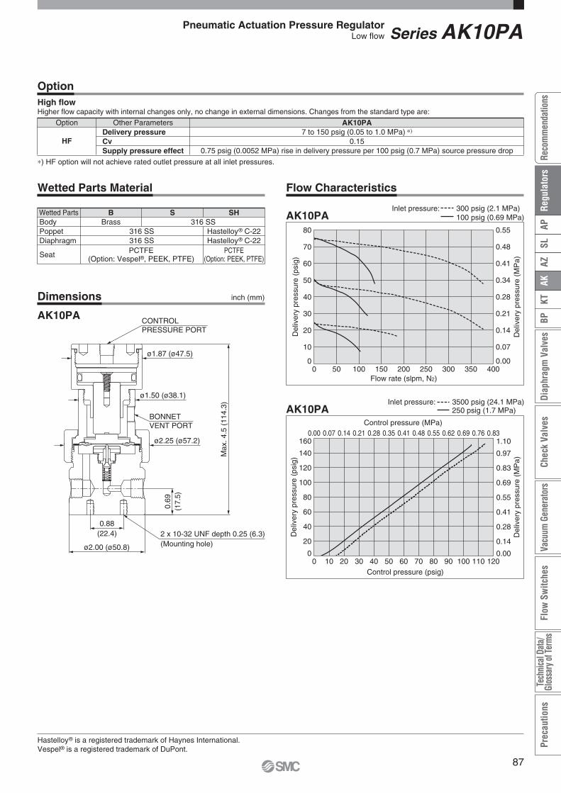
Control pressure (psig)
Del
iver
y pr
essu
re (
psig
)
Control pressure (MPa)
Del
iver
y pr
essu
re (
MP
a)
AK10PA3500 psig (24.1 MPa)Inlet pressure:250 psig (1.7 MPa)
0
20
40
60
80
100
120
140
160
0 10 20 30 40 50 60 70 80 90 100 110 1200.00
0.14
0.28
0.41
0.55
0.69
0.83
0.97
1.100.00 0.07 0.14 0.21 0.28 0.35 0.41 0.48 0.55 0.62 0.69 0.76 0.83
Flow rate (slpm, N2)
Del
iver
y pr
essu
re (
psig
)
Del
iver
y pr
essu
re (
MP
a)
AK10PAInlet pressure: 300 psig (2.1 MPa)
100 psig (0.69 MPa)
0
10
20
30
40
50
60
70
80
0 50 100 150 200 250 300 350 4000.00
0.07
0.14
0.21
0.28
0.34
0.41
0.48
0.55
Option Other Parameters
HFDelivery pressureCvSupply pressure effect
AK10PA7 to 150 psig (0.05 to 1.0 MPa) )
0.150.75 psig (0.0052 MPa) rise in delivery pressure per 100 psig (0.7 MPa) source pressure drop
OptionHigh flowHigher flow capacity with internal changes only, no change in external dimensions. Changes from the standard type are:
Wetted PartsBodyPoppetDiaphragm
Seat
BBrass 316 SS
S
PCTFE(Option: PEEK, PTFE)
SH
Hastelloy® C-22Hastelloy® C-22
Wetted Parts Material
316 SS316 SSPCTFE
(Option: Vespel®, PEEK, PTFE)
Hastelloy® is a registered trademark of Haynes International.Vespel® is a registered trademark of DuPont.
Dimensions
AK10PA
Flow Characteristics
Series AK10PAPneumatic Actuation Pressure RegulatorLow flow
inch (mm)
Max
. 4.5
(11
4.3)
0.88(22.4) 2 x 10-32 UNF depth 0.25 (6.3)
(Mounting hole)ø2.00 (ø50.8)
0.69
(17.
5)
CONTROLPRESSURE PORT
ø1.87 (ø47.5)
ø1.50 (ø38.1)
ø2.25 (ø57.2)
BONNETVENT PORT
) HF option will not achieve rated outlet pressure at all inlet pressures.
87
AZAK
KTBP
Diap
hrag
m V
alve
sCh
eck
Valv
esVa
cuum
Gen
erat
ors
Flow
Sw
itche
sTe
chni
cal D
ata/
Glos
sary
of Te
rms
Prec
autio
nsSL
APRe
com
men
datio
nsRe
gula
tors

2P 3P
4PL 5PC
Porting Configuration (Top View)
IN OUT Extra bottom port (Outlet) Gauge port (Inlet) Gauge port (Outlet)
Actuation control pressure isolated from process gas by two sealsBody material: 316L SS secondary remeltHigh inlet pressure type: Max. 3500 psig (24.1 MPa)Flow capacity Standard: to 30 slpmHastelloy internals available for corrosion resistance100 psig (0.69 MPa) outlet pressure achievable with 80 psig (0.55 MPa) control pressure or less
Series AK15PA
Pneumatic Actuation Pressure Regulator
How to Order
Low flow(Tied-diaphragm)
Operating ParametersDelivery pressureGasSource pressureProof pressure (Inlet)Burst pressureMaximum control pressureAmbient and operating temperatureCvLeak rateConnectionsControl pressure portBonnet portSupply pressure effectInstallationInternal volume
AK15PA7 to 150 psig (0.05 to 1.0 MPa)
Select compatible materials of construction for the gasVacuum to 3500 psig (24.1 MPa)
4500 psig (30.7 MPa)10000 psig (69 MPa)150 psig (1.0 MPa)
-40 to 71 C (No freezing) )
0.091 x 10⁻¹⁰ Pa·m3/sec
NPT female, CompressionNPT 1/8 inchNPT 1/8 inch
0.41 psig (0.0028 MPa) rise in delivery pressure per 100 psig (0.7 MPa) source pressure dropBottom mount
0.53 in3 (8.7 cm3)
Specifications
) -10 to 90 C for Vespel® and PEEK seat. Optional ambient and operating temperature range available. Please contact SMC.
AK15 PA 4PL 4 4SDelivery pressure
PADelivery pressure
7 to 150 psig (0.05 to 1.0 MPa)Code
Material
BS
SH
BodyBrass
316 SS
Poppet
316 SS
Diaphragm
316 SS
Hastelloy® C-22Hastelloy® C-22
Code
Pressure gauge unit 2)
No codeMPA
Unitpsig/bar
MPa
Code
2) Pressure gauge unit MPa or psig/bar selectable. However under Japanese regulation, only MPa is available in Japan.
Connections(Inlet , Outlet )
44T6T
ConnectionsNPT 1/4 inch
1/4 inch compression3/8 inch compression
Code
Seat material
No codeVSPK
MaterialPCTFE (Standard)
Vespel® 3)
PEEK
Code
3) Not available with SH material.
0 0Port Number
Gauge port (Extra bottom outlet , Inlet , Outlet )
No code0
V3121040
Pressure gauge 1)
No gauge port
Code
1) Other range available. Refer to gauge guide (P.94,95).
psig/bar unit
-30 in.Hg to 30 psig-30 in.Hg to 100 psig
0 to 200 psig0 to 1000 psig0 to 4000 psig
-0.1 to 0.2 MPa-0.1 to 0.7 MPa
0 to 1.5 MPa0 to 7 MPa0 to 28 MPa
No pressure gauge (Connections: 1/4 inch NPT)
MPa unit
Ports
2P3P
4PL5PC
BPorts
Refer to the following porting configurations.
MaterialCode
S, SH
a)
88

Wetted PartsBodyPoppetDiaphragmSeat
BBrass 316 SS
S SH
Hastelloy® C-22Hastelloy® C-22
PCTFE (Option: PEEK)
Wetted Parts Material
316 SS316 SS
PCTFE (Option: Vespel®, PEEK)
Hastelloy® is a registered trademark of Haynes International.Vespel® is a registered trademark of DuPont.
Dimensions
AK15PA
Flow Characteristics
Series AK15PAPneumatic Actuation Pressure RegulatorLow flow (Tied-diaphragm)
inch (mm)
Control pressure (psig)
Del
iver
y pr
essu
re (
psig
)
Control pressure (MPa)
Del
iver
y pr
essu
re (
MP
a)AK15PA
3500 psig (24.1 MPa)Inlet pressure:250 psig (1.7 MPa)
0
20
40
60
80
100
120
140
160
0 10 20 30 40 50 60 70 80 90 100 110 1200.00
0.14
0.28
0.41
0.55
0.69
0.83
0.97
1.100.00 0.07 0.14 0.21 0.28 0.34 0.41 0.48 0.55 0.62 0.69 0.76 0.83
Flow rate (slpm, N2)
Del
iver
y pr
essu
re (
psig
)
Del
iver
y pr
essu
re (
MP
a)
AK15PAInlet pressure: 300 psig (2.1 MPa)
100 psig (0.69 MPa)
0
10
20
30
40
50
60
70
80
0 50 100 150 200 250 300 3500.00
0.07
0.14
0.21
0.28
0.34
0.41
0.48
0.55
Max
. 4.5
(11
4.3)
0.88(22.4) 2 x 10-32 UNF depth 0.25 (6.3)
(Mounting hole)ø2.00 (ø50.8)
0.69
(17.
5)
CONTROLPRESSURE PORT
ø1.87 (ø47.5)
ø1.50 (ø38.1)
ø2.25 (ø57.2)
BONNETVENT PORT
89
AZAK
KTBP
Diap
hrag
m V
alve
sCh
eck
Valv
esVa
cuum
Gen
erat
ors
Flow
Sw
itche
sTe
chni
cal D
ata/
Glos
sary
of Te
rms
Prec
autio
nsSL
APRe
com
men
datio
nsRe
gula
tors

Porting Configuration (Top View)
2P 3P
4PL 5PC
Actuation control pressure isolated from process gas by two sealsBody material: 316 SSHigh inlet pressure type Standard: Max. 2300 psig(15.9 MPa)
HR (option): Max. 3000 psig (20.7 MPa)Flow capacity: to 400 slpmHastelloy internals standard100 psig (0.69 MPa) outlet pressure achievable with 80 psig (0.55 MPa)
Series AK14PAT
Pneumatic Actuation Pressure Regulator
How to Order
Intermediate flow(Tied-diaphragm)
T
Operating ParametersDelivery pressureGasSource pressureProof pressure (Inlet)Burst pressureMaximum control pressureAmbient and operating temperatureCvLeak rateConnectionsControl pressure portBonnet portSupply pressure effectInstallationInternal volume
AK14PAT7 to 150 psig (0.05 to 1.0 MPa)
Select compatible materials of construction for the gasVacuum to 2300 psig (15.9 MPa)
4000 psig (27.6 MPa)8000 psig (55.2 MPa)150 psig (1.0 MPa)
-40 to 71 C (No freezing) )
0.451 x 10⁻¹⁰ Pa·m3/sec
NPT female, CompressionNPT 1/8 inchNPT 1/8 inch
1.6 psig (0.011 MPa) rise in delivery pressure per 100 psig (0.7 MPa) source pressure dropBottom mount
1.14 in3 (18.7 cm3)
Specifications
) -10 to 90 C for Vespel® seat.
AK14 PA 4PL 6 6SDelivery pressure
PADelivery pressure
7 to 150 psig (0.05 to 1.0 MPa)Code
Material
Pressure gauge unit 2)
No codeMPA
Unitpsig/bar
MPa
Code
2) Pressure gauge unit MPa or psig/bar selectable. However under Japanese regulation, only MPa is available in Japan.Connections
(Inlet , Outlet )
468
4T6T8T
ConnectionsNPT 1/4 inchNPT 3/8 inchNPT 1/2 inch
1/4 inch compression3/8 inch compression1/2 inch compression
Code
Seat material
No codeVS
MaterialPCTFE (Standard)
Vespel® 3)
Code
Option
3) Not available with SH material.
0 0Port Number
Gauge port (Extra bottom outlet , Inlet , Outlet )
No code0
V3121040
Pressure gauge 1)
No gauge port
Code
1) Other range available. Refer to gauge guide (P.94,95).IN OUT Extra bottom port (Outlet) Gauge port (Inlet) Gauge port (Outlet)
psig/bar unit
-30 in.Hg to 30 psig-30 in.Hg to 100 psig
0 to 200 psig0 to 1000 psig0 to 4000 psig
-0.1 to 0.2 MPa-0.1 to 0.7 MPa
0 to 1.5 MPa0 to 7 MPa0 to 28 MPa
No pressure gauge (Connections: 1/4 inch NPT)
MPa unit
Ports
2P3P
4PL5PC
BPorts
Refer to the following porting configurations.
MaterialCode
S, SH
BS
SH
BodyBrass
316 SS
Poppet
Hastelloy®
C-22Hastelloy®
C-22
Diaphragm Nozzle
316 SS
Hastelloy® C-22
Code
No code
HR
SpecificationStandard
High inlet pressure 4)
(Max. inlet pressure3000 psig (20.7 MPa))
Code
4) Full outlet pressure rating may not be achieved at all inlet pressure.
Pa))
90
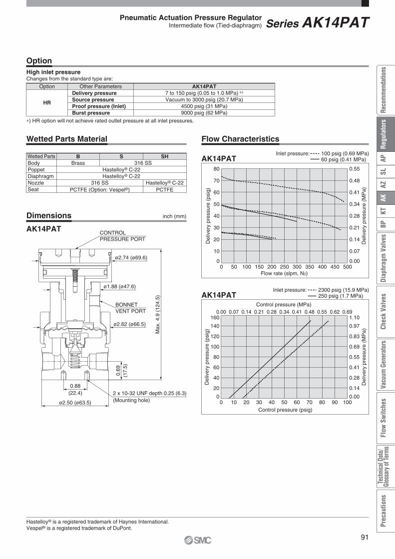
Control pressure (psig)
Del
iver
y pr
essu
re (
psig
)
Control pressure (MPa)
Del
iver
y pr
essu
re (
MP
a)
AK14PAT2300 psig (15.9 MPa)Inlet pressure:250 psig (1.7 MPa)
0
20
40
60
80
100
120
140
160
0 10 20 30 40 50 60 70 80 90 1000.00
0.14
0.28
0.41
0.55
0.69
0.83
0.97
1.100.00 0.07 0.14 0.21 0.28 0.34 0.41 0.48 0.55 0.62 0.69
Flow rate (slpm, N2)
Del
iver
y pr
essu
re (
psig
)
Del
iver
y pr
essu
re (
MP
a)
AK14PATInlet pressure: 100 psig (0.69 MPa)
60 psig (0.41 MPa)
0
10
20
30
40
50
60
70
80
0 50 100 150 200 250 300 350 400 450 5000.00
0.07
0.14
0.21
0.28
0.34
0.41
0.48
0.55
Option Other Parameters
HR
Delivery pressureSource pressureProof pressure (Inlet)Burst pressure
AK14PAT7 to 150 psig (0.05 to 1.0 MPa) )
Vacuum to 3000 psig (20.7 MPa)4500 psig (31 MPa)9000 psig (62 MPa)
OptionHigh inlet pressureChanges from the standard type are:
Wetted Parts Material
Hastelloy® is a registered trademark of Haynes International.Vespel® is a registered trademark of DuPont.
Dimensions
AK14PAT
Flow Characteristics
Series AK14PATPneumatic Actuation Pressure RegulatorIntermediate flow (Tied-diaphragm)
inch (mm)
Wetted PartsBodyPoppetDiaphragmNozzleSeat
BBrass 316 SS
S
PCTFE
SH
Hastelloy® C-22
Hastelloy® C-22Hastelloy® C-22
316 SSPCTFE (Option: Vespel®)
Max
. 4.9
(12
4.5)
0.88(22.4) 2 x 10-32 UNF depth 0.25 (6.3)
(Mounting hole)ø2.50 (ø63.5)
0.69
(17.
5)
CONTROLPRESSURE PORT
ø2.62 (ø66.5)
ø1.88 (ø47.6)
ø2.74 (ø69.6)
BONNETVENT PORT
) HR option will not achieve rated outlet pressure at all inlet pressures.
91
AZAK
KTBP
Diap
hrag
m V
alve
sCh
eck
Valv
esVa
cuum
Gen
erat
ors
Flow
Sw
itche
sTe
chni
cal D
ata/
Glos
sary
of Te
rms
Prec
autio
nsSL
APRe
com
men
datio
nsRe
gula
tors

Porting Configuration (Top View)
2P 3P
4PL 5PC
Actuation control pressure isolated from process gas by two sealsBody material: 316 SSHigh inlet pressure type Standard: Max. 1700 psig(11.7 MPa)
HR (option): Max. 3000 psig (20.7 MPa)Flow capacity Standard: to 800 slpm
HF (Option): to 1000 slpmHastelloy internals available for corrosion resistance100 psig (0.69 MPa) outlet pressure achievable with 80 psig (0.55 MPa) control pressure or less
Series AK12PA
Pneumatic Actuation Pressure Regulator
How to Order
High flow(Tied-diaphragm)
Operating ParametersDelivery pressureGasSource pressureProof pressure (Inlet)Burst pressureMaximum control pressureAmbient and operating temperatureCvLeak rateConnectionsSupply pressure effectInstallationInternal volume
AK12PA7 to 150 psig (0.05 to 1.0 MPa)
Select compatible materials of construction for the gasVacuum to 1700 psig (11.7 MPa)
2550 psig (17.6 MPa)8000 psig (55.2 MPa)150 psig (1.0 MPa)
-40 to 71 °C (No freezing) )
0.651 x 10⁻¹⁰ Pa·m3/sec
NPT female, Compression3.5 psig (0.024 MPa) rise in delivery pressure per 100 psig (0.7 MPa) source pressure drop
Bottom mount1.32 in3 (21.6 cm3)
Specifications
) -10 to 90 °C for Vespel® seat. Optional ambient and operating temperature range available. Please contact SMC.
AK12 PA 4PL 8 8SDelivery pressure
PADelivery pressure
7 to 150 psig (0.05 to 1.0 MPa)Code
Material
BS
SH
BodyBrass
316 SS
Poppet
316 SS
Diaphragm
Hastelloy® C-22Hastelloy® C-22
Code
0 0Port Number
Ports
2P3P
4PL5PC
BPorts
Refer to the following porting configurations.
MaterialCode
S, SH
Pressure gauge unit 2)
No codeMPA
Unitpsig/bar
MPa
Code
2) Pressure gauge unit MPa or psig/bar selectable. However under Japanese regulation, only MPa is available in Japan.
Connections(Inlet , Outlet )
468
4T6T8T
ConnectionsNPT 1/4 inchNPT 3/8 inchNPT 1/2 inch
1/4 inch compression3/8 inch compression1/2 inch compression
Code
Seat material
No codeVS
MaterialPCTFE (Standard)
Vespel® 3)
Code
Option
3) Not available with SH material.
Gauge port (Extra bottom outlet , Inlet , Outlet )
No code0
V3121040
Pressure gauge 1)
No gauge port
Code
1) Other range available. Refer to gauge guide (P.94,95).
psig/bar unit
-30 in.Hg to 30 psig-30 in.Hg to 100 psig
0 to 200 psig0 to 1000 psig0 to 4000 psig
-0.1 to 0.2 MPa-0.1 to 0.7 MPa
0 to 1.5 MPa0 to 7 MPa0 to 28 MPa
No pressure gauge (Connections: 1/4 inch NPT)
MPa unit
No codeHF
HR
SpecificationStandard (Cv:0.65)High flow (Cv:1.1) 4)
High inlet pressure 4)
(Max. inlet pressure3000 psig (20.7 MPa))
Code
4) Full outlet pressure rating may not be achieved at all inlet pressure.
IN OUT Extra bottom port (Outlet) Gauge port (Inlet) Gauge port (Outlet)
urree oror less
92

Control pressure (psig)
Del
iver
y pr
essu
re (
psig
)
Control pressure (MPa)
Del
iver
y pr
essu
re (
MP
a)
AK12PA1700 psig (11.7 MPa)Inlet pressure:250 psig (1.7 MPa)
0
20
40
60
80
100
120
140
160
0 10 20 30 40 50 60 70 80 90 1000.00
0.14
0.28
0.41
0.55
0.69
0.83
0.97
1.100.00 0.07 0.14 0.21 0.28 0.34 0.41 0.48 0.55 0.62 0.69
Flow rate (slpm, N2)
Del
iver
y pr
essu
re (
psig
)
Del
iver
y pr
essu
re (
MP
a)
AK12PAInlet pressure: 100 psig (0.69 MPa) 60 psig (0.41 MPa)
0
10
20
30
40
50
60
70
80
0 100 200 300 400 500 600 700 800 900 10000.00
0.07
0.14
0.21
0.28
0.34
0.41
0.48
0.55
1/2 inch connections
Options1. High flowHigher flow capacity with internal changes only, no change in external dimensions. Changes from the standard type are:
Hastelloy® is a registered trademark of Haynes International.Vespel® is a registered trademark of DuPont.
Dimensions
AK12PA
Flow Characteristics
Series AK12PAPneumatic Actuation Pressure RegulatorLow flow
inch (mm)
Option Other Parameters
HFDelivery pressureCvSupply pressure effect
AK12PA7 to 150 psig (0.05 to 1.0 MPa) )
1.14.2 psig (0.029 MPa) rise in delivery pressure per 100 psig (0.7 MPa) source pressure drop
2. High inlet pressureChanges from the standard type are:
Option Other Parameters
HR
Delivery pressureSource pressureProof pressure (Inlet)Burst pressure
AK12PA7 to 150 psig (0.05 to 1.0 MPa) )
Vacuum to 3000 psig (20.7 MPa)4500 psig (31 MPa)9000 psig (62 MPa)
Wetted PartsBodyPoppetDiaphragmSeat
BBrass 316 SS
S
PCTFE
SH
Hastelloy® C-22
Wetted Parts Material
Hastelloy® C-22316 SS
PCTFE (Option: Vespel®)
2 x 10-32 UNF depth 0.25 (6.3)(Mounting hole)
0.69
(17.
5)
0.88(22.4)
ø2.50 (ø63.5)
Max
. 4.9
(12
4.5)
CONTROLPRESSURE PORT
ø2.62 (ø66.5)
ø1.88 (ø47.6)
ø2.74 (ø69.6)
BONNETVENT PORT
) HR and HF options will not achieve rated outlet pressure at all inlet pressures.
93
AZAK
KTBP
Diap
hrag
m V
alve
sCh
eck
Valv
esVa
cuum
Gen
erat
ors
Flow
Sw
itche
sTe
chni
cal D
ata/
Glos
sary
of Te
rms
Prec
autio
nsSL
APRe
com
men
datio
nsRe
gula
tors

2.13
(54
.1)
9/16-18 UNF
ø2
(ø50
.7)
1.14 (29)
ø2.
28 (
ø57
.8)
3/4 HEX
inch (mm)
inch (mm)
1.94
(49
.3)
ø2
(ø50
.7)
1.14 (29)
ø2.
28 (
ø57
.8)
0.73 (18.5)
NPT 1/4
0.73(18.5)
Stainless steel / Lower mount
For AK/BP series (Installed before shipment / Order separately)
Model
-30 in.Hg to 30 psig-30 in.Hg to 60 psig-30 in.Hg to 100 psig-30 in.Hg to 160 psig
0 to 200 psig0 to 400 psig0 to 1000 psig0 to 4000 psig-0.1 to 0.2 MPa-0.1 to 0.4 MPa-0.1 to 0.7 MPa-0.1 to 1.1 MPa
0 to 1.4 MPa0 to 3 MPa0 to 7 MPa0 to 28 MPa
psig/bar 4)
MPa
00-8300002300-8300002600-8300002100-8300011600-8300002000-8300000700-8300002200-8300002400-8300030400-8300030500-8300030000-8300029700-8300029900-8300030100-8300030200-83000303
(No code)
MPA
V3L1H241040V3L1H241040
unitgauge portPressurerange Unit
Regulator Code 2)Part number 3)
Model
-30 in.Hg to 15 psig-30 in.Hg to 30 psig-30 in.Hg to 60 psig-30 in.Hg to 100 psig-30 in.Hg to 160 psig-30 in.Hg to 200 psig
0 to 200 psig0 to 400 psig0 to 1000 psig0 to 3000 psig0 to 4000 psig-0.1 to 0.1 MPa-0.1 to 0.2 MPa-0.1 to 0.4 MPa-0.1 to 0.7 MPa-0.1 to 1.1 MPa-0.1 to 1.4 MPa
0 to 1.5 MPa0 to 3 MPa0 to 7 MPa0 to 21 MPa0 to 28 MPa
psig/bar 4)
MPa
00-8300010200-8300018400-8300018100-8300018200-8300019600-8300003300-8300019300-8300019400-8300018700-8300023400-8300018300-8300028700-8300028800-8300028900-8300029000-8300029100-8300029200-8300028600-8300028500-8300028400-8300028300-83000282
(No code)
MPA
V15V3L1HV224103040
V15V3L1HV224103040
unitgauge portPressure range Unit
Regulator Code 2)Part number 3)
SSH
material
SpecificationsInstallation
Gas
ConnectionsTemperature range
Accuracy
CleanlinessNo oil
Material
Lower mount
NPT 1/4 inch-40 to 60 C (No freezing)
ASME B40.1 level IVNo oil
Stainless steelPolycarbonate
316L SS316L SS
25% to 75% of the scale: 2%F.S.Other than above: 3%F.S.
(ASME B40.1 Grade B or better)
CaseWindowSocketBourdon tube
For AP/SL/AZ series (Installed before shipment 1) / Order separately)SpecificationsInstallation
Gas
ConnectionsTemperature range
Accuracy
CleanlinessNo oil
Material
Lower mount
1/4 inch face seal (Female)-40 to 60 C (No freezing)
ASME B40.1 level IVNo oil
Stainless steelPolycarbonate
316L SS316L SS
CaseWindowSocketBourdon tube
25% to 75% of the scale: 1%F.S.Other than above: 2%F.S.
(ASME B40.1 Grade A)
Select compatible materials of construction for the gas
Select compatible materialsof construction for the gas
Regulator
Pressure Gauges Guide
1) If one prefers shipment with the pressure gauges installed on the regulator, the material of gasket to be used on the connections will be Nickel (no plated). Please contact SMC for details if one prefers changing this material.
2) When pressure gauge needs to be assembled with regulator when shipment, put this code as gauge port in How to Order.
94

NPT 1/40.42 (10.5)
1.14 (29)
ø2.
28 (
ø58
)
2.1
(53.
5)
2.12
(54
)
ø2
(ø50
.7)
NP
T 1
/4
1.14 (29)
ø2.
28 (
ø57
.8)
2.169 (55.1)
inch (mm)
inch (mm)
Regulator / Pressure Gauges Guide
Brass / Lower mountSpecificationsInstallation
Gas
ConnectionsTemperature range
Accuracy
CleanlinessNo oil
Material
Lower mount
NPT 1/4 inch-40 to 60 C (No freezing)
ASME B40.1 level IVNo oilBrass
PolycarbonateBrass
Phosphor bronze
CaseWindowSocketBourdon tube
Select compatible materialsof construction for the gas
25% to 75% of the scale: 2%F.S.Other than above: 3%F.S.
(ASME B40.1 Grade B or better)
Model
-30 in.Hg to 30 psig-30 in.Hg to 60 psig-30 in.Hg to 100 psig-30 in.Hg to 160 psig
0 to 200 psig0 to 400 psig0 to 1000 psig0 to 4000 psig-0.1 to 0.2 MPa-0.1 to 0.4 MPa-0.1 to 0.7 MPa-0.1 to 1.1 MPa
0 to 1.5 MPa0 to 3 MPa0 to 7 MPa0 to 28 MPa
psig/bar 4)
MPa
00-8300026500-8300017700-8300017800-8300023900-8300021800-8300020500-8300018600-8300017900-8300027800-8300027900-8300028000-8300028100-8300027700-8300027600-8300027500-83000274
(No code)
MPA
V3L1H241040V3L1H241040
unitgauge port Pressure range UnitRegulator Code 2)
Part number 3)
B
material
For AK/BP series (Installed before shipment / Order separately)
Stainless steel / Center back mountModel
-30 in.Hg to 100 psig-30 in.Hg to 160 psig
-0.1 to 0.7 MPa-0.1 to 1.1 MPa
psig/bar 4)
MPa
00-8300022400-8300027200-8300029300-83000294
5)
Pressure range UnitRegulator Code Part number 3)
SpecificationsInstallation
Gas
ConnectionsTemperature range
Accuracy
CleanlinessNo oil
Material
Center back mount
NPT 1/4 inch-40 to 60 C (No freezing)
ASME B40.1 level IVNo oil
Stainless steelPolycarbonate
316L SS316L SS
CaseWindowSocketBourdon tube
Select compatible materialsof construction for the gas
25% to 75% of the scale: 2%F.S.Other than above: 3%F.S.
(ASME B40.1 Grade B or better)
3) Part number of pressure gauge itself. Gauge are shipped separately.4) Under Japanese regulation, psig/bar unit gauge is not sold in Japan.5) Available for special order. Please contact SMC.
95
AZAK
KTBP
Diap
hrag
m V
alve
sCh
eck
Valv
esVa
cuum
Gen
erat
ors
Flow
Sw
itche
sTe
chni
cal D
ata/
Glos
sary
of Te
rms
Prec
autio
nsSL
APRe
com
men
datio
nsRe
gula
tors

1. Do not use the regulator as shutoff valve or safety valve.
2. Do not rotate the adjustment wheel counterclockwise (DECR) under no flow conditions.If the adjustment wheel is rotated counterclockwise (DECR) under no flow conditions but there is residual pressure remaining in outlet side, it may cause damage to the regulator.Decreasing of the setting pressure should be done under flow conditions.
3. Do not pressurize the regulator from outlet side. If high pressure, which exceeds the setting pressure, is supplied from outlet side, it may cause damage to the regulator.
4. Supply gas to the regulator.Rotate the adjustment wheel counterclockwise (DECR) completely to relieve spring force. Then, gradually open the valve at inlet side to supply gas to the regulator. When operating the valve, do not stand in front of the regulator and pressure gauge. If the valve at inlet side is opened rapidly, high pressure gas might be supplied into outlet side of the regulator and it may cause severe damage or burst the device.
5. Adjust pressure.When rotating the adjustment wheel clockwise (INCR), outlet pressure will increase.In order to adjust precisely, the wheel should be adjusted at the desired flow conditions.
6. Decreasing the setting pressure under flow conditions.When decreasing the setting pressure, make sure to open the valve at outlet side to keep flow conditions. When rotating the adjustment wheel counterclockwise (DECR) under flow conditions, setting pressure will decrease.
7. Stop using the regulator immediately if resonance occurs.Loud audible noise as well as vibration of device or fluctuation of outlet pressure (resonance) may occur depending on operating conditions etc. If this situation occurs, stop using the regulator immediately and contact SMC or sales representative.
Operation
WarningSelection
Warning1. Confirm the specifications.
When selecting the product, confirm the operating conditions, such as type of gas, operating pressure (inlet and outlet), flow rate, operating temperature etc., and use within the operating range specified in the catalog. The product may not be suitable for use with specific gases and applications/environments. Check the compatibility of the product materials with the process gas.Design the equipment and select the product by understanding the characteristics of gas.
2. Confirm allowable pressure of any pressure gauges.When installing a pressure gauge to the product, operating pressure should not exceed the maximum allowable pressure of the pressure gauge.
Mounting
Warning1. Confirm the mounting direction of the product.
The high pressure (inlet) port is labeled with an “HP” mark and the low pressure (outlet) port is labeled with an “LP” mark. In the case of two stage regulator, the monitor port of first stage outlet pressure is labeled with “MP” mark.Make sure to connect the port labeled with “HP” mark, to the high pressure. If any of the ports, other than “HP”, are connected to the high pressure, it may cause damage or gas leakage.
2. After installation, check internal leakage (leakage across seat) of the product. Check internal leakage (leakage across seat) with inert gases such as nitrogen, etc., and select the most appropriate test method depending on the application. The following procedures are an example of how a test may be performed. It is intended as an overview and not as an all inclusive description.1) Rotate the adjustment wheel counterclockwise (DECR)
completely to relieve spring force. Then gradually open the valve at inlet side to supply gas to the regulator.
2) Close the valves on the inlet and outlet side and hold for at least 10 minutes. Then confirm the outlet pressure.
3) Rotate the adjustment wheel clockwise (INCR) until the outlet pressure reaches the outlet pressure setting. Then hold for at least 10 minutes and confirm the outlet pressure.
If outlet pressure continues increasing in steps 2) and 3) above, the regulator may have internal leakage (leakage across seat) and you should stop using the regulator immediately and contact SMC or sales representative.
3. Purge hazardous gases from system before removing regulator from system.Before removing regulators from system, fully open regulator by turning adjustment wheel clockwise (INCR), and follow proper procedures to flush system with inert gas such as nitrogen to remove any residual hazardous gases.
Maintenance
Warning1. If a regulator requires repair, contact SMC.
Process Gas Equipment / RegulatorSpecific Product PrecautionsBe sure to read before handling. Refer to back cover for Safety Instructions and P. 145 and 146 and the “Operation Manual” for common precautions. Operation manual is available from the SMC web site. http://www.smcworld.com
96

Operation
Warning1. Do not use the back pressure regulator as
shutoff valve or safety valve.2. Pressure control
1) Rotate the adjustment wheel counterclockwise completely to relieve spring force.
2) Partially open the valve at inlet side to supply gas to the back pressure regulator.
3) Increase the inlet pressure to the setting pressure by rotating the adjustment wheel clockwise.
4) Continue opening the valve at inlet side monitoring the inlet pressure. When the inlet pressure increases above the setting pressure, rotate the adjustment wheel counterclockwise to relieve the inlet pressure to the setting pressure.
5) Open the valve at inlet side completely and confirm that the inlet pressure reaches the setting pressure.
3. Decreasing the setting pressure.When decreasing the setting pressure, make sure to gradually rotate the adjustment wheel counterclockwise until the inlet pressure reaches the setting pressure.
4. Stop using the regulator immediately if resonance occurs.Loud audible noise as well as vibration of device or fluctuation of outlet pressure (resonance) may occur depending on operating conditions, etc. If this situation occurs, stop using the regulator immediately and contact SMC or sales representative.
Selection
Warning1. Confirm the specifications.
When selecting the product, confirm the operating conditions, such as type of gas, operating pressure (inlet and outlet), flow rate, operating temperature etc., and use within the operating range specified in the catalog. Verify flow capacity of regulator and vent or return line, are large enough to vent off gas source without creating excessive backpressure. The product may not be suitable for use with specific gases and applications/environments. Check the compatibility of the product materials with the process gas.Design the equipment and select the product by understanding the characteristics of gas.
2. Confirm allowable pressure of any pressure gauges.When installing pressure gauges to the product, operating pressure should not exceed the maximum allowable pressure of the pressure gauge.
Mounting
Warning1. Confirm the mounting direction of the product.
The high pressure (inlet) port is labeled with an “IN” mark and the low pressure (outlet) port is labeled with an “OUT” mark. Make sure to connect the port labeled with “IN” mark, to the high pressure. If any of the ports, other than “IN”, is connected to the high pressure, it may cause damage or gas leakage.
Maintenance
Warning1. If a back pressure regulator requires repair,
contact SMC.
Process Gas Equipment / Back Pressure RegulatorSpecific Product PrecautionsBe sure to read before handling. Refer to back cover for Safety Instructions and P. 145 and 146 and the “Operation Manual” for common precautions. Operation manual is available from the SMC web site. http://www.smcworld.com
97
AZAK
KTBP
Diap
hrag
m V
alve
sCh
eck
Valv
esVa
cuum
Gen
erat
ors
Flow
Sw
itche
sTe
chni
cal D
ata/
Glos
sary
of Te
rms
Prec
autio
nsSL
APRe
com
men
datio
nsRe
gula
tors

98

Air operated typeDiaphragm Valves: Air operated type (For low pressure)
Diaphragm Valves: Air operated type (For low pressure)
Diaphragm Valves: Air operated type (For high pressure)
Diaphragm Valves: Air operated type (For high pressure and high flow)
Diaphragm Valves: Air operated type (For high flow)
Diaphragm Valves: Air operated type / Two Step
Diaphragm Valves: Air operated type (Metal seated)
Manually operated typeDiaphragm Valves: Manually operated type
Diaphragm Valves: Manually operated type
Diaphragm Valves: Manually operated type (For high pressure and high flow)
Diaphragm Valves: Manually operated type (For high flow)
Diaphragm Valves: Manually operated type (Metal seated)
AP3500AP4500AP3000AP3130 & 3113AP3700AP3571 & 4571AP3200
AP3600AP4600AP3100AP3800 & 3900AP3260
P.100
P.102
P.104
P.106
P.108
P.110
P.112
P.114
P.116
P.118
P.120
P.122
Series PageDiaphragm ValvesDiaphragm Valves
LOTO Options for Diaphragm ValvesDiaphragm Valve Porting GuideDiaphragm Valve/Specific Product Precautions
P.124
P.125
P.126
For ultra high purity (UHP)
99
AZAK
KTBP
Diap
hrag
m V
alve
sCh
eck
Valv
esVa
cuum
Gen
erat
ors
Flow
Sw
itche
sTe
chni
cal D
ata/
Glos
sary
of Te
rms
Prec
autio
nsSL
APRe
com
men
datio
nsRe
gula
tors

Suitable for UHP gas supply lineBody material : 316L SS secondary remeltPneumatically actuated normally closed or normally openLOTO option available as an option (AP3540)Indicator switch available as an option (AP3550)
Series AP3500
How to Order
AP 3 S FV4 FV4540 2PW
Face to face dimension 1)
No code1.75
Dimension2.12 inch (53.8 mm) Standard
1.75 inch (44.5 mm)
Code
Size
3Cv
0.29Code
Material
SH
Body material316L SS secondary remelt
Hastelloy® C-22
Code
Surface finish
No codeMVX
Surface finish Ra max15 in. (0.4 m) Standard
10 in. (0.25 m)7 in. (0.18 m)5 in. (0.13 m)
Code
Ports
2PWPorts
2 portsCode
Connections (Inlet, Outlet)
FV4MV4TW4FV6MV6TW6
Connections1/4 inch face seal (Female)
1/4 inch face seal (Male)1/4 inch tube weld
3/8 inch face seal (Female)3/8 inch face seal (Male)
3/8 inch tube weld
Code
Seat material
No codeVS
MaterialPCTFE (Standard)
Vespel® 2)
Code
Option (AP3550 only)
No codeISCISO
Specification—
N.C. Indicator switch 3)
N.O. Indicator switch 4)
Code
Operating ParametersStatusGasOperating pressureProof pressureBurst pressure Ambient and operating temperatureCv
Leak rate
Across the seat leakSurface finishConnectionsActuation pressureActuation port connectionActuation port locationInstallationInternal volumeMassLOTO (Lockout)
AP3540Normally closed (N.C.)
Select compatible materials of construction for the gas
AP3550 AP3580Normally open (N.O.)
Vacuum to 250 psig (1.7 MPa)Vacuum to 125 psig (0.9 MPa)
NPT 1/8 inchTop
0.68 kg 3)
Option (Part number: AP PL 210) 4)
NPT 1/8 inchTop
0.68 kg 3)
N/A
1000 psig (6.9 MPa)8000 psig (55.2 MPa)
-10 to 71 C (No freezing) 1)
0.292 x 10⁻¹¹ Pa·m3/sec
2 x 10⁻¹⁰ Pa·m3/sec 2)
4 x 10⁻⁹ Pa·m3/sec 2)
Ra max 15 in. (0.4 m) Option: 10 in. (0.25 m), 7 in. (0.18 m), 5 in. (0.13 m)Face seal, Tube weld
70 to 110 psig (0.48 to 0.76 MPa)10-32 UNF thread
SideBottom mount
0.06 in3 (1.07 cm3)0.82 kg 3)
Specifications
(Inlet) (Outlet)
Optional portings and porting configurations available. Please refer to P.125.
1) High temperature available. Please contact SMC.2) Tested with Helium gas inlet pressure 125 psig (0.9 MPa).3) Mass, including individual boxed weight, may vary depending on connections or options.4) Refer to the specification for options. (P.124)
3) Indication of closed status.4) Indication of opened status.
1) Only applies to S material with TW4 connections.
2) Not available with H material.
Model
540550580
Status
Normally closed (N.C.)
Normally open (N.O.)
Maximum operatingpressureCode
125 psig (0.9 MPa)
250 psig (1.7 MPa)
Air operated type(For low pressure)Diaphragm Valve for Ultra High Purity
Inboard leakageOutboard leakage
100

Dimensions
AP3500
S
H
Connectionsinch inch
A B
FV4MV4TW4FV6MV6TW6FV4MV4TW4FV6MV6TW6
1.12 sq.
1.25 dia. )
1.39
1.06
1.93
1.325
1.45
1.08
1.93
1.325
(mm) (mm)
( 28.4)
(ø31.8)
(35.3)
(26.9)
(49.0)
(33.7)
(36.8)
(27.4)
(49.0)
(33.7)
Material
2 x 10-32 UNF depth 0.25 (6.3)(Mounting hole)
ø1.37 (ø34.8)
ø1.46 (ø37.1)
0.44
(11.
2)
1.0 (25.4)
Bottom view
A
AP3550
AP3540/3580
AP
3540
3.4
9 (8
8.6)
AP
3550
3.2
8 (8
3.3)
AP
3580
3.1
7 (8
0.5)
BB
Wetted PartsBodySurface finishDiaphragmSeat
S
Elgiloy®
316L SS secondary remeltElectropolish + Passivation
PCTFE (Option: Vespel®)
Hastelloy® C-22Electropolish
PCTFE
H
Wetted Parts Material
Products such as three port dual valves can be made with monoblock configurations. Please contact SMC for details.
Elgiloy® is a registered trademark of Elgiloy Specialty Metals.Hastelloy® is a registered trademark of Haynes International.Vespel® is a registered trademark of DuPont.
Made to OrderMade toOrder
45
Series AP3500Diaphragm Valve for Ultra High PurityAir operated type (For low pressure)
inch (mm)
) Hastelloy valve body is round not square.
101
AZAK
KTBP
Diap
hrag
m V
alve
sCh
eck
Valv
esVa
cuum
Gen
erat
ors
Flow
Sw
itche
sTe
chni
cal D
ata/
Glos
sary
of Te
rms
Prec
autio
nsSL
APRe
com
men
datio
nsRe
gula
tors

AP 4 S FV6 FV6540 2PW
Face to face dimension 1)
No code1.75
Dimension2.12 inch (53.8 mm) Standard
1.75 inch (44.5 mm)
Code
Size
4Cv0.5
Code
Model
540550580
Status
Normally closed (N.C.)
Normally open (N.O.)
Maximum operatingpressureCode
Material
SH
Body material316L SS secondary remelt
Hastelloy® C-22
Code
Surface finish
No codeMVX
Surface finish Ra max15 in. (0.4 m) Standard
10 in. (0.25 m)7 in. (0.18 m)5 in. (0.13 m)
Code
Ports
2PWPorts
2 portsCode
Connections (Inlet, Outlet)
FV4MV4TW4FV6MV6TW6
Connections1/4 inch face seal (Female)
1/4 inch face seal (Male)1/4 inch tube weld
3/8 inch face seal (Female)3/8 inch face seal (Male)
3/8 inch tube weld
Code
Option (AP4550 only)
No codeISCISO
Specification—
N.C. indicator switch 3)
N.O. indicator switch 4)
Code
Suitable for UHP gas supply lineBody material: 316L SS secondary remeltPneumatically actuated normally closed or normally openLOTO option available as an option (AP4540)Indicator switch available as an option (AP4550)
Operating ParametersStatusGasOperating pressureProof pressureBurst pressureAmbient and operating temperatureCv
Leak rate
Across the seat leakSurface finishConnectionsActuation pressureActuation port connectionActuation port locationInstallationInternal volumeMassLOTO (Lockout)
AP4540Normally closed (N.C.)
Select compatible materials of construction for the gas
AP4550 AP4580Normally open (N.O.)
Vacuum to 250 psig (1.7 MPa)Vacuum to 125 psig (0.9 MPa)
NPT 1/8 inchTop
0.68 kg 3)
Option (Part number: AP PL 210) 4)
NPT 1/8 inchTop
0.68 kg 3)
N/A
1000 psig (6.9 MPa)8000 psig (55.2 MPa)
-10 to 71 C (No freezing) 1)
0.52 x 10⁻¹¹ Pa·m3/sec
2 x 10⁻¹⁰ Pa·m3/sec 2)
4 x 10⁻⁹ Pa·m3/sec 2)
Ra max 15 in. (0.4 m) Option: 10 in. (0.25 m), 7μin. (0.18 m), 5 in. (0.13 m)Face seal, Tube weld
70 to 110 psig (0.48 to 0.76 MPa)10-32 UNF thread
SideBottom mount
0.06 in3 (1.07 cm3)0.82 kg 3)
Specifications
(Inlet) (Outlet)
Optional portings and porting configurations available. Please refer to P.125.
Series AP4500
3) Indication of closed status.4) Indication of opened status.
1) Only applies to S material with TW4 connections.
1) High temperature available. Please contact SMC.2) Tested with Helium gas inlet pressure 125 psig (0.9 MPa).3) Mass, including individual boxed weight, may vary depending on connections or options.4) Refer to the specification for options. (P.124)
Seat material
No codeVS
MaterialPCTFE (Standard)
Vespel® 2)
Code
2) Not available with H material.
How to Order
125 psig (0.9 MPa)
250 psig (1.7 MPa)
Air operated type(For low pressure)Diaphragm Valve for Ultra High Purity
Inboard leakageOutboard leakage
102

Dimensions
AP4500
S
H
Connectionsinch inch
A B
FV4MV4TW4FV6MV6TW6FV4MV4TW4FV6MV6TW6
1.12 sq.
1.25 dia. )
1.39
1.06
1.93
1.325
1.45
1.08
1.93
1.325
(mm) (mm)
( 28.4)
(ø31.8)
(35.3)
(26.9)
(49.0)
(33.7)
(36.8)
(27.4)
(49.0)
(33.7)
Material
ø1.37 (ø34.8)
ø1.46 (ø37.1)
0.44
(11.
2)
1.0 (25.4)
A
AP4550
AP4540/4580
AP
4540
3.4
9 (8
8.6)
AP
4550
3.2
8 (8
3.3)
AP
4580
3.1
7 (8
0.5)
BB
Wetted PartsBodySurface finishDiaphragmSeat
S
Elgiloy®
316L SS secondary remeltElectropolish + Passivation
PCTFE (Option: Vespel®)
Hastelloy® C-22Electropolish
PCTFE
H
Wetted Parts Material
2 x 10-32 UNF depth 0.25 (6.3)(Mounting hole)
Bottom view
Products such as three port dual valves can be made with monoblock configuration. Please contact SMC for details.
Elgiloy® is a registered trademark of Elgiloy Specialty Metals.Hastelloy® is a registered trademark of Haynes International.Vespel® is a registered trademark of DuPont.
Made to OrderMade toOrder
45
Series AP4500Diaphragm Valve for Ultra High PurityAir operated type (For low pressure)
inch (mm)
) Hastelloy valve body is round not square.
103
AZAK
KTBP
Diap
hrag
m V
alve
sCh
eck
Valv
esVa
cuum
Gen
erat
ors
Flow
Sw
itche
sTe
chni
cal D
ata/
Glos
sary
of Te
rms
Prec
autio
nsSL
APRe
com
men
datio
nsRe
gula
tors

How to Order
AP30 00 2PW FV4 FV4SModel
0002
Cv0.230.28
Code
Material
SH
Body material316L SS secondary remelt
Hastelloy® C-22
Code
Surface finish
No codeMVX
Surface finish Ra max15 in. (0.4 m) Standard
10 in. (0.25 m)7 in. (0.18 m)5 in. (0.13 m)
Code
Ports
2PWPorts
2 portsCode
Optional portings and porting configurations available. Please refer to P.125.
Connections (Inlet, Outlet)
FV4MV4TW4FV6MV6TW6
Connections1/4 inch face seal (Female)
1/4 inch face seal (Male)1/4 inch tube weld
3/8 inch face seal (Female)3/8 inch face seal (Male)
3/8 inch tube weld
Code
Option
No codeIS
Specification—
Indicator switch 3)
Code
Face to face dimension 1)
No code1.75
Dimension2.12 inch (53.8 mm) Standard
1.75 inch (44.5 mm)
Code
Series AP3000Suitable for UHP gas supply lineBody material: 316L SS secondary remeltPneumatically actuated normally closedHigh pressure type: Max. 3000 psig (20.7 MPa)LOTO option available as an optionIndicator switch available as an option
Operating ParametersStatusGasOperating pressureProof pressureBurst pressureAmbient and operating temperatureCv
Leak rate
Across the seat leakSurface finishConnectionsActuation pressureActuation port connectionActuation port locationInstallationInternal volumeMassLOTO (Lockout)
AP3000 AP3002Normally closed (N.C.)
Select compatible materials of construction for the gasVacuum to 3000 psig (20.7 MPa)
4000 psig (27.6 MPa)8000 psig (55.2 MPa)
-10 to 71 C (No freezing)
2 x 10-11 Pa·m3/sec2 x 10-10 Pa·m3/sec 1)
4 x 10⁻⁹ Pa·m3/sec 1)
Ra max 15 in. (0.4 m) Option: 10 in. (0.25 m), 7 in. (0.18 m), 5 in. (0.13 m)Face seal, Tube weld
70 to 110 psig (0.48 to 0.76 MPa)NPT 1/8 inch
TopBottom mount
0.06 in3 (1.07 cm3)1.27 kg 2)
Option (Part number: AP PL 210) 3)
Specifications
(Inlet) (Outlet)
0.23 0.28
3) Indication of opened/closed status.
1) Tested with Helium gas inlet pressure 1000 psig (6.9 MPa).2) Mass, including individual boxed weight, may vary depending on connections or options.3) Refer to the specification for options. (P.124)
Seat material
No codeVS
MaterialPCTFE (Standard)
Vespel® 2)
Code
2) Not available with H material.
1) Only applies to S material with TW4 connections.
Air operated type(For high pressure)Diaphragm Valve for Ultra High Purity
Inboard leakageOutboard leakage
104

Dimensions
AP3000
S
H
Connectionsinch inch
A B
FV4MV4TW4FV6MV6TW6FV4MV4TW4FV6MV6TW6
1.12 sq.
1.25 dia. )
1.39
1.06
1.93
1.325
1.45
1.08
1.93
1.325
(mm) (mm)
( 28.4)
(ø31.8)
(35.3)
(26.9)
(49.0)
(33.7)
(36.8)
(27.4)
(49.0)
(33.7)
Material
2 x 10-32 UNF depth 0.25 (6.3)(Mounting hole)
ø1.98 (ø50.3)
0.44
(11.2
)
1.0(25.4)
A
4.1
(104
.1)
BB
Products such as three port dual valves can be made with monoblock configurations. Please contact SMC for details.
Elgiloy® is a registered trademark of Elgiloy Specialty Metals.Hastelloy® is a registered trademark of Haynes International.Vespel® is a registered trademark of DuPont.
Wetted PartsBody Surface finishDiaphragmSeat
S316L SS secondary remeltElectropolish + Passivation
PCTFE (Option: Vespel®)
Hastelloy® C-22Electropolish
PCTFE
H
Elgiloy®
Wetted Parts Material
Made to OrderMade toOrder
45
Series AP3000Diaphragm Valve for Ultra High PurityAir operated type (For high pressure)
inch (mm)
) Hastelloy valve body is round not square.
105
AZAK
KTBP
Diap
hrag
m V
alve
sCh
eck
Valv
esVa
cuum
Gen
erat
ors
Flow
Sw
itche
sTe
chni
cal D
ata/
Glos
sary
of Te
rms
Prec
autio
nsSL
APRe
com
men
datio
nsRe
gula
tors

Series AP3130 & 3113
Air operated type(For high pressure and high flow)Diaphragm Valve for Ultra High Purity
Suitable for UHP gas supply lineBody material: 316L SS secondary remeltPneumatically actuated normally closedHigh pressure type: 20.7 MPa and 9 MPaDesigned for bulk specialty gas (BSGS) deliveryLOTO option available as an option
How to Order
AP31 30 2PW MV8 MV8S
1330
Maximum operating pressure1300 psig (9.0 MPa)
3000 psig (20.7 MPa) 1)
Cv1.00.7
Code
Material
Model
SH
Body material316L SS secondary remelt
Hastelloy® C-22 2)
Code
Surface finish
No codeM
Surface finish Ra max15 in. (0.4 m) Standard
10 in. (0.25 m)
Code
1) 2400 psig (16.5MPa) for connection size 3/4 inch.
Connections (Inlet, Outlet)
FV4MV4TW6FV8MV8TW8FV12MV12TW12
Connections1/4 inch face seal (Female)
1/4 inch face seal (Male)3/8 inch tube weld
1/2 inch face seal (Female)1/2 inch face seal (Male)
1/2 inch tube weld3/4 inch face seal (Female)
3/4 inch face seal (Male)3/4 inch tube weld
Code
Ports
2PWPorts
2 portsCode
Wetted Parts Material
(Inlet) (Outlet)
Operating ParametersStatusGasOperating pressureProof pressureBurst pressureAmbient and operating temperatureCv 2)
Leak rate
Across the seat leakSurface finishConnectionsActuation pressureActuation port connectionActuation port locationInstallationInternal volumeMassLOTO (Lockout)
AP3130AP3113Normally closed (N.C.)
Select compatible materials of construction for the gas
4500 psig (31 MPa)10000 psig (69 MPa)
-10 to 65 C (No freezing)
2 x 10-11 Pa·m3/sec2 x 10-10 Pa·m3/sec 3)
4 x 10⁻⁹ Pa·m3/sec 3)
Ra max 15 in. (0.4 m) Option: 10 in. (0.25 m)Face seal, Tube weld
70 to 110 psig (0.48 to 0.76 MPa)NPT 1/8 inch
TopBottom mount
0.36 in3 (6.0 cm3) for body1.27 kg 4)
Option (Part number: AP PL 210) 5)
Vacuum to 3000 psig (20.7 MPa) 1)
0.7
Vacuum to 1300 psig (9.0 MPa)
1.0
Specifications
1) Maximum operating pressure 2400 psig (16.5 MPa) for connection size 3/4 inch.2) Figure of 1/2 inch connection.3) Tested with Helium gas inlet pressure 500 psig (3.5 MPa).4) Mass, including individual boxed weight, may vary depending on connections or options.5) Refer to the specification for options. (P.124)
Wetted PartsBodySurface finishSpringDiaphragmPoppetSeat
S
Elgiloy®
316L SS secondary remeltElectropolish + Passivation
316L SS
316L SS PCTFE (Option: Vespel®)
Hastelloy® C-22ElectropolishInconel® 600
Hastelloy® C-22PCTFE
H
Seat material
No codeVS
MaterialPCTFE (Standard)
Vespel® 3)
Code
3) Not available with H material.
2) Special export controls apply to Hastelloy body with 1/2 inch or greater size connection.
Inboard leakageOutboard leakage
Option
No codeIS
Specification—
Indicator switch 4)
Code
4) Indication of opened/closed status.
106

Dimensions
AP3130 & 3113
Connectionsinch
A
FV4MV4TW6FV8MV8TW8FV12MV12TW12
2.00
1.375
2.425
1.79
3.50
3.25
(mm)
(50.8)
(34.9)
(61.6)
(45.4)
(88.9)
(82.6)
2 x 10-32 UNF depth 0.35 (8.9)(Mounting hole)
ø1.98 (ø50.3)
ø2.0 (ø50.8)0.
715
(18.
2)
1.5 (38.1)
Bottom view
A A
A A
AP
3130
5.0
2 (1
27.5
)A
P31
13 5
.76
(146
.3)
Elgiloy® is a registered trademark of Elgiloy Specialty Metals.Hastelloy® is a registered trademark of Haynes International.Inconel® is a registered trademark of Special Metal.Vespel® is a registered trademark of DuPont.
45
Series AP3130 & 3113Diaphragm Valve for Ultra High PurityAir operated type (For high pressure and high flow)
inch (mm)
107
AZAK
KTBP
Diap
hrag
m V
alve
sCh
eck
Valv
esVa
cuum
Gen
erat
ors
Flow
Sw
itche
sTe
chni
cal D
ata/
Glos
sary
of Te
rms
Prec
autio
nsSL
APRe
com
men
datio
nsRe
gula
tors

How to Order
AP37 00 MV8MV8 00SModel
0008
StatusNormally closed (N.C.)Normally open (N.O.)
Code
Material
SBody material
316L SS secondary remeltCode
Surface finish
MVX
Surface finish Ra max15 in. (0.4 m) Standard
10 in. (0.25 m)7 in. (0.18 m)5 in. (0.13 m)
CodeNo code
Connections (Inlet , Outlet )
TW6FV8MV8TW8FV12MV12TW12
Connections3/8 inch tube weld
1/2 inch face seal (Female)1/2 inch face seal (Male)
1/2 inch tube weld3/4 inch face seal (Female)
3/4 inch face seal (Male)3/4 inch tube weld
Code
Seat material
No codeVS
MaterialPCTFE (Standard)
Vespel®
Code
Purge port 1)
00M00BMB
InletNone
AvailableNone
Available
OutletNoneNone
AvailableAvailable
Code
Purge port option
No codeC
Specification—
Capped purge port
Code
Suitable for UHP gas supply lineBody material: 316L SS secondary remeltPneumatically actuated normally closed or normally openPurge ports and monoblock configurations available
(Inlet) (Outlet)
1) 1/4 inch face seal (Male) as standard.
Wetted PartsBodySurface finishDiaphragmSeat
316L SS secondary remeltElectropolish + Passivation
316L SSPCTFE (Option: Vespel®)
S
Wetted Parts Material
Series AP3700
Option (AP3700 Only)
No codeISCISO
Specification—
N.C. indicator switch 2)
N.O. indicator switch 3)
Code
2) Indication of closed status.3) Indication of opened status.
Operating ParametersStatusGasOperating pressureProof pressureBurst pressure Ambient and operating temperatureCv
Leak rate
Across the seat leakSurface finishConnectionsActuation pressureActuation port connectionActuation port locationInstallationInternal volumeMass
AP3708AP3700Normally closed (N.C.)
Select compatible materials of construction for the gasVacuum to 250 psig (1.7 MPa)
500 psig (3.4 MPa)1000 psig (6.9 MPa)
-10 to 71 C (No freezing)2.8
2 x 10-11 Pa·m3/sec2 x 10-10 Pa·m3/sec 1)
4 x 10⁻⁹ Pa·m3/sec 1)
Ra max 15 in. (0.4 m) Option: 10 in.(0.25 m), 7 in.(0.18 m), 5 in.(0.13 m)Face seal, Tube weld
80 to 100 psig (0.55 to 0.7 MPa)10-32 UNF thread
SideBottom mount
0.76 in3 (12.52 cm3)1.54 kg 2)
Normally open (N.O.)
Specifications
1) Tested with Helium gas inlet pressure 125 psig (0.9 MPa).2) Mass, including individual boxed weight, may vary depending on connections or options.
Porting Configuration
Air operated type(For high flow)Diaphragm Valve for Ultra High Purity
Inboard leakageOutboard leakage
108

Dimensions
AP3700
Connectionsinch
A
TW6FV8MV8TW8FV12MV12TW12
4.25
2.65
4.25
3.20
4.25
(mm)(108.0)
(67.3)
(108.0)
(81.3)
(108.0)
ø2.5 (ø63.5)
1.62
(41
.1)
5.0
(127
.0)
0.56
(14.
2)
1.0
(25.
4)
1.64 0.06
(41.7)
2.0 (50.8)
1.73 (43.9)
A A
2 x 10-32 UNF depth 0.25 (6.3)(Mounting hole)
Change of porting configuration and products such as three port dual valves can be made. Please contact SMC for details.
Vespel® is a registered trademark of DuPont.
Made to OrderMade toOrder
Series AP3700Diaphragm Valve for Ultra High PurityAir operated type (For high flow)
inch (mm)
109
AZAK
KTBP
Diap
hrag
m V
alve
sCh
eck
Valv
esVa
cuum
Gen
erat
ors
Flow
Sw
itche
sTe
chni
cal D
ata/
Glos
sary
of Te
rms
Prec
autio
nsSL
APRe
com
men
datio
nsRe
gula
tors

Two step mode - metered flow and full openTwo separate actuation portsSoft start valve to minimize vacuum chamber pressurization turbulenceMetered flow adjustable AP3571: 10 to 200 slpm
AP4571: 10 to 350 slpmPneumatically actuated normally closedBody material: 316L SS secondary remelt
At 80 psig (0.55 MPa) of N2
Series AP3571 & 4571
How to Order
AP 3 S FV4 FV4 M571 2PW
Face to face dimension 2)
No code1.75
Face to face2.12 inch (53.8 mm) Standard
1.75 inch (44.5 mm)
Code
Size
34
Cv0.290.5
Code
Material
SBody material
316L SS secondary remeltCode
Surface finish
No codeMVX
Surface finish Ra max15 in. (0.4 m) Standard
10 in. (0.25 m)7 in. (0.18 m)5 in. (0.13 m)
Code
Ports
2PWPorts
2 portsCode
Connections (Inlet, Outlet)
FV4MV4TW4FV6MV6TW6
Connections1/4 inch face seal (Female)
1/4 inch face seal (Male)1/4 inch tube weld 1)
3/8 inch face seal (Female)3/8 inch face seal (Male)
3/8 inch tube weld
Code
Metered flow
XXX(3 digits)
Metered adjusted flow in slpmCode
(Inlet) (Outlet)
Optional portings and porting configurations available. Please refer to P.125.
2) Only applies to S material with TW4 connections.
Model
571Mode
Two step modeStatusCode
Normally closed (N.C.)
Air operated typeTwo StepDiaphragm Valve for Ultra High Purity
Operating ParametersStatusGasOperating pressureProof pressureBurst pressureAmbient and operating temperatureCv
Leak rate
Across the seat leakSurface finishConnectionsActuation pressureActuation port connectionActuation port locationInstallationInternal volumeAdjustable range of metered flow 2)
Tolerance of metered flow
AP4571AP3571
0.29
Normally closed (N.C.)Select compatible materials of contruction of the gas
Vacuum to 125 psig (0.9 MPa)200 psig (1.4 MPa)
1000 psig (6.9 MPa) 0 to 51 C (No freezing)
2x10-11 Pa·m3/sec2x10-10 Pa·m3/sec 1)
4x10⁻⁹ Pa·m3/sec 1)
Ra max 15 in. (0.4 m) Option: 10 in. (0.25 m), 7 in. (0.18 m), 5 in. (0.13 m)Face seal, Tube weld
70 to 110 psig (0.48 to 0.76 MPa)M5 thread (2 each)
Sides (2 each)Bottom mount
0.06 in3 (1.07 cm3)
6 slpm10 slpm15 slpm20 slpm
0.5
10 to 200 slpm
N/A
10 to 350 slpm
25 slpm
Specifications
1) Tested with Helium gas inlet pressure 125 psig (0.9 MPa)2) At 80 psig (0.55 MPa) N2
Inboard leakageOutboard leakage
10 to 20 slpm21 to 50 slpm51 to 100 slpm101 to 200 slpm201 to 350 slpm
1) TW4 is not available with AP4571
050
Metered adjusted flow in slpm at 80 psig (0.55 MPa) N2.Replace XXX with flow rate using 3 digits, example 50 slpm = "050"Adjustable Range: AP3571= 10 to 200 slpm, AP4571= 10 to 350 slpm
nce
110

Dimensions
AP3571 & 4571
Connectionsinch inch
A B
FV4MV4TW4FV6MV6TW6
Material
S 1.12 sq.
1.39
1.06
1.93
1.325
(mm) (mm)
( 28.4)
(35.3)
(26.9)
(49.0)
(33.7)
ø1.72 (ø43.7)
0.44
(11.2
)M
ax. 3
.63
(92.
2)
A
BB
45
Elgiloy® is a registered trademark of Elgiloy Specialty Metals.
Series AP3571 & 4571Diaphragm Valve for Ultra High PurityAir operated type (Two Step)
inch (mm)
Wetted partsBodySurface finishDiaphragmSeat
316L SS secondary remeltElectropolish + Passivation
Elgiloy®
PCTFE
S
Wetted Parts Material
1.0(25.4)2 x 10-32 UNF depth 0.25 (6.3)(Mounting hole)
111
AZAK
KTBP
Diap
hrag
m V
alve
sCh
eck
Valv
esVa
cuum
Gen
erat
ors
Flow
Sw
itche
sTe
chni
cal D
ata/
Glos
sary
of Te
rms
Prec
autio
nsSL
APRe
com
men
datio
nsRe
gula
tors

Suitable for UHP gas supply lineBody material: 316L SS secondary remeltAll metal wetted partsPneumatically actuated normally closedIndicator switch available as an option
Series AP3200
How to Order
AP32 00 2PW MV4 MV4S
Face to face dimension 1)
No code1.75
Dimension2.12 inch (53.8 mm) Standard
1.75 inch (44.5 mm)
Code
Air operated
Material
SBody material
316L SS secondary remeltCode
Surface finish
No codeMVX
Surface finish Ra max15 in. (0.4 m) Standard
10 in. (0.25 m)7 in. (0.18 m)5 in. (0.13 m)
Code
Ports
2PWPorts
2 portsCode
Optional portings and porting configurations available. Please refer to P.125.
Connections (Inlet, Outlet)
FV4MV4TW4FV6MV6TW6
Connections1/4 inch face seal (Female)
1/4 inch face seal (Male)1/4 inch tube weld
3/8 inch face seal (Female)3/8 inch face seal (Male)
3/8 inch tube weld
Code
Option
No codeIS
Specification—
Indicator switch 2)
Code
Wetted PartsBody Surface finishDiaphragm
S316L SS secondary remeltElectropolish + Passivation
Elgiloy®
Wetted Parts Material
(Inlet) (Outlet)
1) Only applies to TW4 connections.
2) Indication of opened/closed status
Operating ParametersStatusGasOperating pressureProof pressureBurst pressureAmbient and operating temperatureCv
Leak rate
Across the seat leakSurface finishConnectionsActuation pressureActuation port connectionActuation port locationInstallationInternal volumeMass
AP3200Normally closed (N.C.)
Select compatible materials of construction for the gasVacuum to 125 psig (0.9 MPa)
1000 psig (6.9 MPa)8000 psig (55.2 MPa)
-10 to 100 C (No freezing)0.27
2 x 10-11 Pa·m3/sec2 x 10-10 Pa·m3/sec 1)
1 x 10⁻⁷ Pa·m3/sec 1)
Ra max 15 in. (0.4 m) Option: 10 in. (0.25 m), 7 in. (0.18 m), 5 in. (0.13 m)Face seal, Tube weld
70 to 110 psig (0.48 to 0.76 MPa)NPT 1/8 inch
TopBottom mount
0.06 in3 (1.07 cm3)1.27 kg 2)
Specifications
1) Tested with Helium gas inlet pressure 125 psig (0.9 MPa).2) Mass, including individual boxed weight, may vary depending on connections or options.
Inboard leakageOutboard leakage
Air operated type(Metal seated)Diaphragm Valve for Ultra High Purity
112

Dimensions
AP3200
Connectionsinch inch
A B
FV4MV4TW4FV6MV6TW6
Material
S 1.12 sq.
1.39
1.06
1.93
1.325
(mm) (mm)
( 28.4)
(35.3)
(26.9)
(49.0)
(33.7)
2 x 10-32 UNF depth 0.25 (6.3)(Mounting hole)
ø1.98 (ø50.3)
0.44
(11.2
)
1.0(25.4)
A
4.0
(104
.1)
BB
45
Elgiloy® is a registered trademark of Elgiloy Specialty Metals.
Series AP3200Diaphragm Valve for Ultra High PurityAir operated type (Metal seated)
inch (mm)
113
AZAK
KTBP
Diap
hrag
m V
alve
sCh
eck
Valv
esVa
cuum
Gen
erat
ors
Flow
Sw
itche
sTe
chni
cal D
ata/
Glos
sary
of Te
rms
Prec
autio
nsSL
APRe
com
men
datio
nsRe
gula
tors

How to Order
AP 3 2PW FV4 FV4650
Face to face dimension 1)
No code1.75
Dimension2.12 inch (53.8 mm) Standard
1.75 inch (44.5 mm)
Code
Size
3Cv
0.29Code
Model
600625
650
657
KnobMulti turn round knob1/4 turn lever knob
Pull twist knob with LOTO
Code
Material
SH
Body material316L SS secondary remelt
Hastelloy® C-22
Code
Surface finish
No codeMVX
Surface finish Ra max15 in. (0.4 m) Standard
10 in. (0.25 m)7 in. (0.18 m)5 in. (0.13 m)
Code
Connections (Inlet, Outlet)
FV4MV4TW4FV6MV6TW6
Connections1/4 inch face seal (Female)
1/4 inch face seal (Male)1/4 inch tube weld
3/8 inch face seal (Female)3/8 inch face seal (Male)
3/8 inch tube weld
CodeInstallation option
No codeP
InstallationBottom mount (Standard)
Panel Installation 3)
Code
Option (AP3650 only)
No codeISH
Specification—
Indicator switch 4)
Code
Series AP3600Suitable for UHP gas supply lineBody material: 316L SS secondary remeltLOTO standard with AP3657, optional AP3625Indicator switch available as an option (AP3650)
Operating ParametersGasOperating pressureProof pressureBurst pressureAmbient and operating temperatureCv
Leak rate
Across the seat leakSurface finishConnectionsInstallationInternal volumeMass
Knob
Operational Safety Device (OSD)LOTO (Lockout)
AP3600
0.36 kg 3)
Multi turn round knob
N/A
0.45 kg 3)
1/4 turn lever knob 4)
Option (Part number: AP PL227) 6)
Option (Part number: AP PL225) 6)
0.73 kg 3)
N/A
1/4 turn round knob withopen/close indication window
0.4 kg 3)
Pull twist knob with LOTO 5)
Standard
Select compatible materials of construction for the gasVacuum to 3000 psig (20.7 MPa)
4000 psig (27.6 MPa)8000 psig (55.2 MPa)
-40 to 71 C (No freezing) 1)
0.292 x 10⁻¹¹ Pa·m3/sec
2 x 10⁻¹⁰ Pa·m3/sec 2)
4 x 10⁻⁹ Pa·m3/sec 2)
Ra max 15 in. (0.4 m) Option: 10 in. (0.25 m), 7 in. (0.18 m), 5 in. (0.13 m)Face seal, Tube weld
Bottom mount (Option: panel mount)0.06 in3 (1.07 cm3)
AP3625 AP3650 AP3657
Specifications
Wetted PartsBodySurface finishDiaphragmSeat
S
Elgiloy®
316L SS secondary remelt Electropolish + Passivation
PCTFE (Option: Vespel®)
Hastelloy® C-22Electropolish
PCTFE
H
Wetted Parts Material
(Inlet) (Outlet)
S
3) Panel mounting hole: dia.0.78 inch (19.8 mm).
4) Indication of opened/closed status.
1) -10 to 90 °C for Vespel® seat. High temperature available. Please contact SMC.2) Tested with Helium gas inlet pressure 250 psig (1.7 MPa).3) Mass, including individual boxed weight, may vary depending on connections or options.4) Optional lever color available. Please contact SMC.5) Handle must be pulled to turn open from closed.6) Refer to the specification for options. (P.124)
1) Only applies to S material with TW4 connections.
Ports
2PWPorts
2 portsCode
Optional portings and porting configurations available. Please refer to P.125.
Seat material
No codeVS
MaterialPCTFE (Standard)
Vespel® 2)
Code
2) Not available with H material.
1/4 turn round knob with open/close indication window
Inboard leakageOutboard leakage
Diaphragm Valve for Ultra High Purity Manually operated type
Elgiloy® is a registered trademark of Elgiloy Specialty Metals.Hastelloy® is a registered trademark of Haynes International.Vespel® is a registered trademark of DuPont.
114

Products such as three port dual valves can be made with monoblock configurations. Please contact SMC for details.
Made to OrderMade toOrder
Dimensions
AP3600 AP3625
AP3650 AP3657
2 x 10-32 UNF depth 0.25 (6.3)(Mounting hole)
2 x 10-32 UNF depth 0.25 (6.3)(Mounting hole)
ø2.12 (ø53.8)2.05 (52.1)
ø0.94 (ø23.9)1.48 (37.6)
0.44
(11
.2)
0.44
(11
.2)
3.0
(76.
2)
2.94
(74
.7)
1.0(25.4)
1.0(25.4)
ABB
ABB
2 x 10-32 UNF depth 0.25 (6.3)(Mounting hole)
ø1.88 (ø47.8)
0.44
(11
.2)
3.02
(76
.7)
1.0(25.4)
ABB
0.4 (10.2)ø1.87 (ø47.5)
0.44
(11
.2)
3.6
(91.
4)
0.13
(3.
3)
1.0(25.4)
A
BB
45 45
45
45
Series AP3600Diaphragm Valve for Ultra High PurityManually operated type
inch (mm)
2 x 10-32 UNF depth 0.25 (6.3)(Mounting hole)
S
H
ConnectionsA B
inch inch(mm) (mm)FV4MV4TW4FV6MV6TW6FV4MV4TW4FV6MV6TW6
1.12 sq.
)1.25 dia.
( 28.4)
(ø31.8)
(35.3)
(26.9)
(49.0)
(33.7)
(36.8)
(27.4)
(49.0)
(33.7)
1.39
1.06
1.93
1.325
1.45
1.08
1.93
1.325
Material
) Hastelloy valve body is round not square.
115
AZAK
KTBP
Diap
hrag
m V
alve
sCh
eck
Valv
esVa
cuum
Gen
erat
ors
Flow
Sw
itche
sTe
chni
cal D
ata/
Glos
sary
of Te
rms
Prec
autio
nsSL
APRe
com
men
datio
nsRe
gula
tors

How to Order
AP 4 2PW FV6 FV6650
Face to face dimension 1)
No code1.75
Dimension2.12 inch (53.8 mm) Standard
1.75 inch (44.5mm)
Code
Size
4Cv0.5
Code
Model
600625
650
657
KnobMulti turn round knob1/4 turn lever knob
Pull twist knob with LOTO
Code
Material
SH
Body material316L SS secondary remelt
Hastelloy® C-22
Code
Surface finish
No codeMVX
Surface finish Ra max15 in. (0.4 m) Standard
10 in. (0.25 m)7 in. (0.18 m)
5 in. (0.13 m)
Code
Connections (Inlet, Outlet)
FV4MV4TW4FV6MV6TW6
Connections1/4 inch face seal (Female)
1/4 inch face seal (Male)1/4 inch tube weld
3/8 inch face seal (Female)3/8 inch face seal (Male)
3/8 inch tube weld
CodeInstallation option
No codeP
InstallationBottom mount (Standard)
Panel Installation 3)
Code
Option (AP4650 only)
No codeISH
Specification—
Indicator switch 4)
Code
Series AP4600Suitable for UHP gas supply lineBody material: 316L SS secondary remeltLOTO standard with AP4657, optional AP4625Indicator switch available as an option (AP4650)
Operating ParametersGasOperating pressureProof pressureBurst pressureAmbient and operating temperatureCv
Leak rate
Across the seat leakSurface finishConnectionsInstallationInternal volumeMass
Knob
Operational Safety Device (OSD)LOTO (Lockout)
AP4600
0.36 kg 3)
Multi turn round knob
N/A
0.45 kg 3)
1/4 turn lever knob 4)
Option (Part number: AP PL227) 6)
Option (Part number: AP PL225) 6)
0.73 kg 3)
N/A
0.4 kg 3)
Pull twist knob with LOTO 5)
Standard
Select compatible materials of construction for the gasVacuum to 250 psig (1.7 MPa)
1000 psig (6.9 MPa)8000 psig (55.2 MPa)
-40 to 71 C (No freezing) 1)
0.52 x 10⁻¹¹ Pa·m3/sec
2 x 10⁻¹⁰ Pa·m3/sec 2)
4 x 10⁻⁹ Pa·m3/sec 2)
Ra max 15 in. (0.4 m) Option: 10 in. (0.25 m), 7 in. (0.18 m), 5 in. (0.13 m)Face seal, Tube weld
Bottom mount (Option: panel mount)0.06 in3 (1.07 cm3)
AP4625 AP4650 AP4657
Specifications
Wetted PartsBody Surface finishDiaphragmSeat
S
Elgiloy®
316L SS secondary remelt Electropolish + Passivation
PCTFE(Option: Vespel®)
Hastelloy® C-22Electropolish
PCTFE
H
Wetted Parts Material
(Inlet) (Outlet)
S
3) Panel mounting hole: dia.0.78 inch (19.8 mm).
4) Indication of opened/closed status.
1) Only applies to S material with TW4 connections.
Ports
2PWPorts
2 portsCode
Optional portings and porting configurations available. Please refer to P.125.
Seat material
No codeVS
MaterialPCTFE (Standard)
Vespel® 2)
Code
2) Not available with H material.
1) -10 to 90 C for Vespel® seat. High temperature available. Please contact SMC.2) Tested with Helium gas inlet pressure 250 psig (1.7 MPa).3) Mass, including individual boxed weight, may vary depending on connections or options.4) Optional lever color available. Please contact SMC.5) Handle must be pulled to turn open from closed.6) Refer to the specification for options. (P.124)
1/4 turn round knob withopen/close indication window
Inboard leakageOutboard leakage
Diaphragm Valve for Ultra High Purity Manually operated type
Elgiloy® is a registered trademark of Elgiloy Specialty Metals.Hastelloy® is a registered trademark of Haynes International.Vespel® is a registered trademark of DuPont.
1/4 turn round knob withopen/close indication window
116

Products such as three port dual valves can be made with monoblock configurations. Please contact SMC for details.
Made to OrderMade toOrder
Dimensions
AP4600 AP4625
AP4650 AP4657
2 x 10-32 UNF depth 0.25 (6.3)(Mounting hole)
2 x 10-32 UNF depth 0.25 (6.3)(Mounting hole)
ø2.12 (ø53.8)2.05 (52.1)
ø0.94 (ø23.9)1.48 (37.6)
0.44
(11
.2)
0.44
(11
.2)
3.0
(76.
2)
2.94
(74
.7)
1.0(25.4)
1.0(25.4)
ABB
ABB
2 x 10-32 UNF depth 0.25 (6.3)(Mounting hole)
ø1.88 (ø47.8)
0.44
(11
.2)
3.02
(76
.7)
1.0(25.4)
ABB
0.4 (10.2)ø1.87 (ø47.5)
0.44
(11
.2)
3.6
(91.
4)
0.13
(3.
3)
1.0(25.4)
A
BB
45 45
45
45
Series AP4600Diaphragm Valve for Ultra High PurityManually operated type
inch (mm)
S
H
ConnectionsA B
inch inch(mm) (mm)FV4MV4TW4FV6MV6TW6FV4MV4TW4FV6MV6TW6
1.12 sq.
)1.25 dia.
( 28.4)
(ø31.8)
(35.3)
(26.9)
(49.0)
(33.7)
(36.8)
(27.4)
(49.0)
(33.7)
1.39
1.06
1.93
1.325
1.45
1.08
1.93
1.325
Material
2 x 10-32 UNF depth 0.25 (6.3)(Mounting hole)
) Hastelloy valve body is round not square.
117
AZAK
KTBP
Diap
hrag
m V
alve
sCh
eck
Valv
esVa
cuum
Gen
erat
ors
Flow
Sw
itche
sTe
chni
cal D
ata/
Glos
sary
of Te
rms
Prec
autio
nsSL
APRe
com
men
datio
nsRe
gula
tors

Series AP3100
Manually operated type(For high pressure and high flow)Diaphragm Valve for Ultra High Purity
Suitable for UHP gas supply lineBody material: 316L SS secondary remeltHigh pressure type: 20.7 MPa and 9 MPaDesigned for bulk specialty gas (BSGS) deliveryLOTO standard with AP3157, optional AP3125
How to Order
AP31 00 2PW MV8 MV8S
Material
SH
Body material316L SS secondary remelt
Hastelloy® C-22 2)
Code Surface finish
No codeM
15 in. (0.4 m) Standard10 in. (0.25 m)
Code
Connections (Inlet, Outlet)
FV4MV4TW6FV8MV8TW8FV12MV12TW12
Connections1/4 inch face seal (Female)
1/4 inch face seal (Male)3/8 inch tube weld
1/2 inch face seal (Female)1/2 inch face seal (Male)
1/2 inch tube weld3/4 inch face seal (Female)
3/4 inch face seal (Male)3/4 inch tube weld
Code
Ports
2PWPorts
2 portsCode
(Inlet) (Outlet)
Operating ParametersGas
Operating pressure
Proof pressureBurst pressureAmbient and operating temperatureCv 3)
Leak rate
Across the seat leakSurface finishConnectionsInstallationInternal volumeMass
Knob
Operational Safety Device (OSD)
LOTO (Lockout)
AP3100
0.7
Multi turn round knob (1 1/2 turn)
N/A
AP3102
1.3
Vacuum to 3000 psig(20.7 MPa) 1)
Vacuum to 1300 psig(9.0 MPa)
AP3125Select compatible materials of construction for the gas
4500 psig (31 MPa)10000 psig (69 MPa)
-40 to 65 C (No freezing) 2)
2 x 10-11 Pa·m3/sec2 x 10-10 Pa·m3/sec 4)
4 x 10⁻⁹ Pa·m3/sec 4)
Ra max 15 in. (0.4 m) Option: 10 in. (0.25 m)Face seal , Tube weld
Bottom mount0.36 in3 (6.0 cm3)
1.27 kg 5)
AP3150
Vacuum to 1300 psig (9.0 MPa)
1.0
1/4 turn lever knob 6)
Option(Part number: AP PL227) 9)
Option(Part number: AP PL225) 9)
1/4 turn round knobwith open/close indication window 7)
N/A
Pull twist knob 8)
Standard
AP3157
Specifications
Model
00022550
57
3000 psig (20.7 MPa) 1)
1300 psig (9.0 MPa)3000 psig (20.7 MPa) 1)
1300 psig (9.0 MPa)
1300 psig (9.0 MPa)
Cv
0.71.31.01.0
1.0
Knob
Multi turn round knob
1/4 turn lever knob1/4 turn round knob
Pull twist knobwith LOTO
Indicator switchHandle 4)
Code
1) 2400 psig (16.5 MPa) for connection size 3/4 inch.
Seat material
No codeVS
MaterialPCTFE (Standard)
Vespel® 3)
Code
3) Not available with H material.
Elgiloy® is a registered trademark of Elgiloy Specialty Metals. Hastelloy® is a registered trademark of Haynes International.Inconel® is a registered trademark of Special Metal. Vespel® is a registered trademark of DuPont.
2) Special export controls apply to Hastelloy body with 1/2 inch or greater size connection.
1) Maximum operating pressure 2400 psig (16.5 MPa) for connection size 3/4 inch.2) -10 to 90 C for Vespel® seat.3) Figure of 1/2 inch connection.4) Tested with Helium gas inlet pressure 500 psig (3.5 MPa).5) Mass, including individual boxed weight, may vary depending on connections or options.6) Optional lever color available. Please contact SMC.7) Optional indicator switch available. Please contact SMC.8) Handle must be pulled to turn open from closed.9) Refer to the specification for options. (P.124)
Maximum operatingpressure
Surface finish Ra max
Inboard leakageOutboard leakage
Vacuum to 3000 psig(20.7 MPa) 1)
Option (AP3150 only)
No code
ISH
Specification—
Code
4) Indication of opened/closed status.
118

Dimensions
AP3125
Connectionsinch
A
FV4MV4TW6FV8MV8TW8FV12MV12TW12
2.00
1.375
2.425
1.79
3.50
3.25
(mm)
(50.8)
(34.9)
(61.6)
(45.4)
(88.9)
(82.6)
AP3157 ø1.87 (ø47.5)AP3150 ø1.88 (ø47.8)AP3100 ø2.12 (ø53.8)
2.05 (51.8)
1.48 (37.3)0.
715
(18.
2)3.
86 (
98.0
)
0.71
5(1
8.2)
A A
A A
AP
3157
4.4
6 (1
13.3
)A
P31
50 3
.94
(100
.1)
AP
3100
3.
74 (
95.0
)ø0.94 (ø23.9)
Wetted Parts Material
2 x 10-32 UNF depth 0.35 (8.9)(Mounting hole)
ø2.0 (ø50.8)
1.5 (38.1)
Bottom view
A A
45
Wetted PartsBodySurface finishSpringDiaphragmPoppetSeat
S
Elgiloy®
316L SS secondary remeltElectropolish + Passivation
316L SS
316L SS PCTFE (Option: Vespel®)
Hastelloy® C-22ElectropolishInconel® 600
Hastelloy® C-22PCTFE
H
Series AP3100Diaphragm Valve for Ultra High PurityManually operated type (For high pressure and high flow)
inch (mm)
119
AZAK
KTBP
Diap
hrag
m V
alve
sCh
eck
Valv
esVa
cuum
Gen
erat
ors
Flow
Sw
itche
sTe
chni
cal D
ata/
Glos
sary
of Te
rms
Prec
autio
nsSL
APRe
com
men
datio
nsRe
gula
tors

How to Order
AP 3800 MV8MV8 00S MModel
3800
3900
KnobRound knob with open/close
indication windowPull twist knob with LOTO
Code
Material
SBody material
316L SS secondary remeltCode Surface finish
No codeMVX
Surface finish Ra max15 min. (0.4mm) Standard
10 in. (0.25 m) 7 in. (0.18 m)5 in. (0.13 m)
Code
Connections (Inlet , Outlet )
TW6FV8MV8TW8FV12MV12TW12
Connections3/8 inch tube weld
1/2 inch face seal (Female)1/2 inch face seal (Male)
1/2 inch tube weld3/4 inch face seal (Female)
3/4 inch face seal (Male)3/4 inch tube weld
Code
Seat material
No codeVS
MaterialPCTFE (Standard)
Vespel®
Code
Purge port 1)
00M00BMB
InletNone
AvailableNone
Available
OutletNoneNone
AvailableAvailable
Code
Purge port option
No codeC
Specification—
Capped purge port
Code
Suitable for UHP gas supply lineBody material: 316L SS secondary remeltPurge ports and monoblock configurations availableLOTO available (AP3900)
(Inlet) (Outlet)
1) 1/4 inch face seal (Male) as standard.
Wetted PartsBodySurface finishDiaphragmSeat
S316L SS secondary remeltElectropolish + Passivation
316L SSPCTFE (Option: Vespel®)
Wetted Parts Material
Select compatible materials of construction for the gasVacuum to 250 psig (1.7 MPa)
500 psig (3.4 MPa)1000 psig (6.9 MPa)
-40 to 71 C (No freezing) 1)
2.82 x 10⁻¹¹ Pa·m3/sec
2 x 10⁻¹⁰ Pa·m3/sec 2)
4 x 10⁻⁹ Pa·m3/sec 2)
Ra max 15 in. (0.4 m) Option: 10 in.(0.25 m), 7 in.(0.18 m), 5 in.(0.13 m)Face seal, Tube weld
Bottom mount0.76 in3 (12.52 cm3)
Operating ParametersGasOperating pressureProof pressureBurst pressureAmbient and operating temperatureCv
Leak rate
Across the seat leakSurface finishConnectionsInstallationInternal volumeMassKnobLOTO (Lockout)
AP3900AP3800
1.36 kg 3)
Round knob with open/close indication windowN/A
1.45 kg 3)
Pull twist knob 4)
Standard
Specifications
1) -10 to 90 C for Vespel® seat.2) Tested with Helium gas inlet pressure 125 psig (0.9 MPa).3) Mass, including individual boxed weight, may vary depending on connections or options.4) Handle must be pulled to turn open from closed.
Porting Configuration
Inboard leakageOutboard leakage
Vespel® is a registered trademark of DuPont.
Series AP3800 & 3900
Manually operated type(For high flow)Diaphragm Valve for Ultra High Purity
120

Dimensions
AP3800 AP3900
Connectionsinch
A
TW6FV8MV8TW8FV12MV12TW12
4.25
2.65
4.25
3.20
4.25
(mm)(108.0)
(67.3)
(108.0)
(81.3)
(108.0)
1.62
(41
.1)
1.64 0.06
(41.7)
A A
1.62
(41
.1)
1.64 0.06
(41.7)
A A
ø2.25 (ø57.2)
ø2.25 (ø57.2)
2.85
(72
.4)
3.64
(92
.5)
0.56
(14
.2)
0.56
(14
.2)
1.0
(25.
4)
1.0
(25.
4)
2.0 (50.8)
2.0 (50.8)
1.73 (43.9) 2 x 10-32 UNF depth 0.25 (6.3)(Mounting hole) 1.73 (43.9) 2 x 10-32 UNF depth 0.25 (6.3)
(Mounting hole)
Change of porting configuration and products such as three port dual valves can be made. Please contact SMC for details.
Made to OrderMade toOrder
Series AP3800 & 3900Diaphragm Valve for Ultra High PurityManually operated type (For high flow)
inch (mm)
121
AZAK
KTBP
Diap
hrag
m V
alve
sCh
eck
Valv
esVa
cuum
Gen
erat
ors
Flow
Sw
itche
sTe
chni
cal D
ata/
Glos
sary
of Te
rms
Prec
autio
nsSL
APRe
com
men
datio
nsRe
gula
tors

AP32 60 2PW MV4 MV4S
Face to face dimension 1)
No code1.75
Dimension2.12 inch (53.8 mm) Standard
1.75 inch (44.5 mm)
Code
Manually operated type
Material
SBody Material
316L SS secondary remeltCode
Surface finish
No codeMVX
Surface finish Ra max15 in. (0.4 m) Standard
10 in. (0.25 m)7 in. (0.18 m)5 in. (0.13 m)
Code
Ports
2PWPorts
2 portsCode
Optional portings and porting configurations available. Please refer to P.125.
Connections (Inlet, Outlet)
FV4MV4TW4FV6MV6TW6
Connections1/4 inch face seal (Female)
1/4 inch face seal (Male)1/4 inch tube weld
3/8 inch face seal (Female)3/8 inch face seal (Male)
3/8 inch tube weld
Code
Installation option
No codeP
InstallationBottom mount (Standard)
Panel Installation 2)
Code
Series AP3260Suitable for UHP gas supply lineBody material: 316L SS secondary remeltAll metal wetted parts
Wetted PartsBodySurface finishDiaphragm
S316L SS secondary remeltElectropolish + Passivation
Elgiloy®
Wetted Parts Material
(Inlet) (Outlet)
2) Panel mounting hole: dia. 0.78 inch (19.8mm).
1) Only applies to TW4 connections.
Operating ParametersGasOperating pressureProof pressureBurst pressureAmbient and operating temperatureCv
Leak rate
Across the seat leakSurface finishConnectionsInstallationInternal volumeMassKnob
AP3260Select compatible materials of construction for the gas
Vacuum to 125 psig (0.9 MPa)1000 psig (6.9 MPa)8000 psig (55.2 MPa)
-40 to 90 C (No freezing)0.27
2 x 10-11 Pa·m3/sec2 x 10-10 Pa·m3/sec 1)
1 x 10⁻⁷ Pa·m3/sec 1)
Ra max 15 in. (0.4 m) Option: 10 in. (0.25 m), 7 in. (0.18 m), 5 in. (0.13 m)Face seal, Tube weld
Bottom mount (Option: panel mount)0.06 in3 (1.07 cm3)
0.36 kg 2)
Multi turn round knob
Specifications
1) Tested with Helium gas inlet pressure 125 psig (0.9 MPa).2) Mass, including individual boxed weight, may vary depending on connections or options.
Inboard leakage Outboard leakage
Elgiloy® is a registered trademark of Elgiloy Specialty Metals.
Manually operated type(Metal seated)Diaphragm Valve for Ultra High Purity
How to Order
122

Dimensions
AP3260
Connectionsinch inch
A B
FV4MV4TW4FV6MV6TW6
Material
S 1.12 sq.
1.39
1.06
1.93
1.325
(mm) (mm)
( 28.4)
(35.3)
(26.9)
(49.0)
(33.7)
2 x 10-32 UNF depth 0.25 (6.3)(Mounting hole)
ø2.12 (ø53.8)
0.44
(11
.2)
3.0
(76.
2)
1.0(25.4)
A
BB
45
Series AP3260Diaphragm Valve for Ultra High PurityManually operated type (Metal seated)
inch (mm)
123
AZAK
KTBP
Diap
hrag
m V
alve
sCh
eck
Valv
esVa
cuum
Gen
erat
ors
Flow
Sw
itche
sTe
chni
cal D
ata/
Glos
sary
of Te
rms
Prec
autio
nsSL
APRe
com
men
datio
nsRe
gula
tors

AP PL210
This item is not included and shall be prepared by customer.
AP PL225
This item is not included and shall be prepared by customer.
AP PL227
Lockout Device/For Air Operated Valve (Order Separately)
Product number: AP PL210
Lockout Device/For Manually Operated Valve (Order Separately)
Product number: AP PL225
FeatureLockable by installing the AP PL210 to the actuation port of air operated valve(only available for N.C. with actuation port connection NPT 1/8 inch)Prevent accidental valve opening by manually shutting off actuation pressureLockable only in the closed positionAccept standard pad lock with 1/4 inch shackleActuation port connection:10-32 UNF threadActuation port pressure rating: Maximum 150 psig (1.0 MPa)
OperationPush top button down and twist to close the valve. This feature allows the valve to stay in closed position even if actuation pressure is supplied into an actuation port. Valve opens by repositioning the button, then pressurizing the actuation port.
SeriesAP3000, AP3113, AP3130, AP3540, AP4540, AP3200
FeatureLockable by installing the AP PL225 to the manually operated valve(only available for lever knob)Lockable in the closed positionAccept standard pad lock with 1/4 inch shackle.
SeriesAP3125, AP3625, AP4625
Hook for Operational Safety Device (OSD) (Order Separately)
Product number: AP PL227Feature
Secure valve in the closed position by installing the AP PL227 to the top of the handle.Prevents accidental opening of the valve.
SeriesAP3125, AP3625, AP4625
LOTO Optionsfor Diaphragm Valves
Made to order specifications
124

How to Order
AP 3650 4PWMSAvailable series
303235453646
SeriesAP3000 seriesAP3200 seriesAP3500 seriesAP4500 seriesAP3600 seriesAP4600 series
Code
MaterialsStainless steel
Connections(Number indicates the port location)
No codeFV4MV4TW4FV6MV6TW6
ConnectionsNo port
1/4 inch face seal (Female)1/4 inch face seal (Male)
1/4 inch tube weld3/8 inch face seal (Female)
3/8 inch face seal (Male)3/8 inch tube weld
Code
OptionDepends on the product series
Port Specifications
Ports
2PW2PWA2PWB2PWC3PWD3PWE3PWF3PWG3PWH3PWJ4PWK4PWL4PWM4PWN
Ports
2 ports
3 ports
4 ports
Refer to the following(Port specification)
ConfigurationCode
Surface finishDepends on the product series
MV4 TW4( ) ( )
FV4 FV4( ) ( )
Valves are illustrated top view looking down through the valve.The traditional flow direction is INLET to OUTLET, but AP Tech valves may be employed in either flow direction.Port locations are indicated by numbers.INLET (Upstream) is defined as a port connected to the region below the valve seat. It is illustrated with an arrow pointing towards the valve body or an "empty" triangle on the schematic.OUTLET (Downstream) is defined as a port connected to the region above the seat and below the diaphragm. It is illustrated with an arrow pointing away from the valve body or a "filled" triangle on the schematic.
Examples of The Many Available options
AP3000S2PWC FV4 MV4
AP3625S3PWD TW4 MV4 FV4
AP3550S2PWB TW4 FV4
AP3650S4PWM MV4 TW4 FV4 FV4
4PWK 4PWL 4PWM 4PWN
3PWD 3PWE 3PWG 3PWH3PWF 3PWJ
2PW 2PWA 2PWB 2PWC
Inlet(Upstream)
Mounting hole
Top view (Mounting hole on bottom)
Outlet(Downstream)
Bottom port(Upstream)
2 P
ort
s3
Po
rts
4 P
ort
s
Diaphragm Valve
Porting GuideMade to order specifications
INLET OUTLETPorting Symbols
125
AZAK
KTBP
Diap
hrag
m V
alve
sCh
eck
Valv
esVa
cuum
Gen
erat
ors
Flow
Sw
itche
sTe
chni
cal D
ata/
Glos
sary
of Te
rms
Prec
autio
nsSL
APRe
com
men
datio
nsRe
gula
tors

Operation (Manually operated type)
Warning4. When closing the valve, rotate the handle
clockwise until it completely stops.There is the internal stop in the handle or in the valve body. Rotate the handle clockwise until the internal stop is reached and it completely stops.
5. When closing the valve with LOTO feature, rotate the handle fully clockwise until the stop.(AP3657, AP4657, AP3157, AP3900)When the handle is fully clockwise, the indicator plate roller is aligned with a vertical slot in the handle allowing the handle to drop downward. This feature prevents the valve from being accidentally opened.
6. When opening the valve, rotate the handle counterclockwise until it completely stops.There is the internal stop in the handle. Rotate the handle counterclockwise until the internal stop is reached and it completely stops.
7. When opening the valve with LOTO feature, the handle must first be lifted up, away from the valve body, and rotated counterclockwise until it completely stops.(AP3657, AP4657, AP3157, AP3900)When valve is closed, handle will not rotate as the fixed indicator plate roller is positioned within the vertical slot in the handle.The handle must first be lifted up away from the valve body and rotated counterclockwise until it completely stops.
8. Do not use a tool when rotating the handle.When the handle is rotated with a tool, it may apply excessive torque to the handle or inside the valve body and it may cause damage. Rotate the handle by hand.
9. When locking the valve with LOTO feature in the closed position, use safety lockout hasp.(AP3657, AP4657, AP3157, AP3900)The valve with LOTO feature has a built in LOTO capability. When using LOTO feature, rotate the handle clockwise and insert safety lockout hasp into lock stem slot.
Selection
Warning1. Confirm the specifications.
This product is used in gas delivery systems to shutoff gas flow. When selecting the product, confirm the operating conditions, such as type of gas, operating pressure (inlet and outlet), flow rate, actuating pressure, operating temperature etc., and use within the operating range specified in the catalog. The product may not be suitable for use with specific gases and applications/environments. Check the compatibility of the product materials with the process gas.Design the equipment and select the product by understanding the characteristics of gas.
Operation (Air operate type)
Warning1. Use nitrogen or clean dry air as actuation
pressure.2. Confirm the valve type (N.C. or N.O.).
In the case of N.C. (Normally Closed), valve will open when applying actuation pressure to the valve actuator connection and valve will close when actuation pressure is vented to atmospheric pressure. In the case of N.O. (Normally Open), its actuation mechanism is opposite to the N.C. type. Valve will close when applying actuation pressure to the valve actuator connection.
3. Apply actuation pressure within the range of specifications.
Maintenance
Warning1. If a valve requires repair, contact SMC.
Mounting
Warning1. Confirm the mounting direction of the product.
Inlet ports are labeled with an “IN” mark. The outlet ports are usually not labeled but may be labeled with an “OUT” mark. Orient the valve as specified by the system designer.
2. Connect actuation pressure to the valve actuator connection. (Air operated type)Use nitrogen or clean dry air for actuation pressure. The connection may be a 1/8 inch NPT female thread or 10-32 female thread or M5 depending on the valve model.
3. After installation, check internal leakage (leakage across seat) with inert gases.Perform a helium leak test depending on applications.
Process Gas Equipment / Diaphragm Valve Specific Product PrecautionsBe sure to read before handling. Refer to back cover for Safety Instructions and P. 145 and 146 and the “Operation Manual” for common precautions. Operation manual is available from the SMC web site. http://www.smcworld.com
126

Check Valve AP64 P.128
Series PageCheck ValveCheck Valve
Vacuum GeneratorVacuum Generator ModuleVacuum Generator Module
AP7 & 70AP71AP72
P.130
P.132
P.134
Series PageVacuum GeneratorVacuum Generator
Flow SwitchFlow Switch (For high flow)
AP74AP74B
P.136
P.138
Check Valve, Vacuum Generator and Flow Switch/Specific Product Precautions P.140
Series PageFlow SwitchFlow Switch
127
AZAK
KTBP
Diap
hrag
m V
alve
sCh
eck
Valv
esVa
cuum
Gen
erat
ors
Flow
Sw
itche
sTe
chni
cal D
ata/
Glos
sary
of Te
rms
Prec
autio
nsSL
APRe
com
men
datio
nsRe
gula
tors

Simple design with free of springs and poppetsReseals with minimal back pressureLow cracking pressure
Series AP64
Check Valve
AP64 MV4 MV4SMaterial
SBody material
316L SS secondary remeltCode
Surface finish
No codeMX
Surface finish Ra max15 in. (0.4 m) Standard
10 in. (0.25 m)5 in. (0.13 m)
CodeConnections (Inlet, Outlet)
MV4FV4TW4MV6FV6TW6
Connections1/4 inch face seal (Male)
1/4 inch face seal (Female)1/4 inch tube weld
3/8 inch face seal (Male)3/8 inch face seal (Female)
3/8 inch tube weld
Code
Seat material
No codeNP
MaterialViton® (Standard)
Neoprene®
Code
Operating ParametersGasInlet pressureCracking pressure 1)
Maximum backpressureProof pressureBurst pressureAmbient and operating temperatureCv
Leak rate
Surface finishConnectionsInternal volumeMass
AP64Select compatible materials of construction for the gas
Vacuum to 3500 psig (24.1 MPa)3 psi (0.023 MPa) differential 2)
3500 psig (24.1 MPa)4000 psig (27.6 MPa)10000 psig (69 MPa)
-10 to 71 C (No freezing)0.4 max
2 x 10-11 Pa·m3/sec2 x 10-11 Pa·m3/sec 3)
Ra max 15 in. (0.4 m) Option: 10 in. (0.25 m), 5 in. (0.13 m)Face seal, Tube weld
0.122 in.3 (2 cm3)0.02 kg 4)
Specifications
(Inlet) (Outlet)
1) Cracking pressure is a nominal value which may vary depending on the application and operating conditions.2) 6 psi (0.04 MPa) differential for Neoprene® seat.3) Tested with inlet pressure 500 psig (3.5 MPa).4) Mass, including individual boxed weight, may vary depending on connections or options.
Wetted PartsBodySurface finishSeal
S316L SS secondary remeltElectropolish + PassivationViton® (Option: Neoprene®)
Wetted Parts Material
Inboard leakageOutboard leakage
Viton®, Neoprene® are registered trademarks of DuPont.
How to Order
128

Construction
AP64
Dimensions
AP64
Connectionsinch inch
MV4MV4FV4FV4TW4
MV4FV4FV4MV4TW4
0.62
0.93
0.34
1.19
1.50
1.190.91
inchA B C
1.812.122.432.121.25
(mm)Inlet Outlet (mm)
(15.7)
(23.6)
(8.6)
(30.2)
(38.1)
(30.2)(23.1)
(mm)(46.0)(53.8)(61.7)(53.8)(31.8)
inch (mm)
IN
IN
Flow direction
The body is fully welded.
The interior volume and the surface area are reduced as much as possible.
Seal(O-Ring)
Completely cleaned flow pass
OUT
0.57 (14.5)
OUT
3/4 inch (Hexagonal)
AB
C
Heat lotmarking
Check Valve Series AP64
129
AZAK
KTBP
Diap
hrag
m V
alve
sCh
eck
Valv
esVa
cuum
Gen
erat
ors
Flow
Sw
itche
sTe
chni
cal D
ata/
Glos
sary
of Te
rms
Prec
autio
nsSL
APRe
com
men
datio
nsRe
gula
tors

Max. vacuum pressure: -26 in.Hg (-88 kPa)AP70 series
Compact Fine vacuum efficiency
AP7 series All connections available with all ports
Series AP7 & 70
Vacuum Generator
Operating ParametersGas (Inlet N2 port)Gas (Vacuum port)N2 Inlet pressureVacuum port maximum pressureProof pressure (Vacuum)Burst pressureMaximum vacuum pressureAmbient and operating temperature
Connections
Mass
AP7N2
Select compatible materials of construction for the gas70 to 110 psig (0.48 to 0.76 MPa)
3500 psig (24.1 MPa)5000 psig (34.5 MPa)10000 psig (69 MPa)-26 in.Hg (-88 kPa) 1)
-40 to 71 C
Face seal, Tube weld
Face seal, Tube weldFace seal, Tube weld
0.11 kg 2)
1/4 inch face seal (Male)3/8 inch face seal (Male)
0.13 kg 2)
AP70
1) At inlet pressure 80 psig (0.55 MPa) and flow rate 60 slpm.2) Mass, including individual boxed weight, may vary depending on connections or options.
Specifications
Wetted PartsBody
S316L SS
Wetted Parts Material
InletVentVacuum
AP 7 3PW MV4 MV6 FV4SModel
7Feature
Optional connections availableCode
Material
SBody material
316L SSCode
Ports
3PWPorts
3 portsCode
(Inlet) (Vent) (Vacuum)
How to Order
AP 70 MV4 MV6 FV4SModel
70Feature
Compact and high performanceCode
Material
SBody material
316L SSCode
MV4Connections
1/4 inch face seal (Male)Code
Connections (Inlet N2)
MV6Connections
3/8 inch face seal (Male)CodeConnections (Vent)
MV4FV4TW4MV6FV6TW6
Connections1/4 inch face seal (Male)
1/4 inch face seal (Female)1/4 inch tube weld
3/8 inch face seal (Male)3/8 inch face seal (Female)
3/8 inch tube weld
CodeConnections (Vacuum)
MV4FV4TW4MV6FV6TW6
Connections1/4 inch face seal (Male)
1/4 inch face seal (Female)1/4 inch tube weld
3/8 inch face seal (Male)3/8 inch face seal (Female)
3/8 inch tube weld
CodeConnections (Inlet N2, Vent, Vacuum)
(Inlet) (Vent) (Vacuum)
130

Dimensions
Connections(Inlet) inchMV4FV4TW4MV6FV6TW6
1.62
1.25
2.13
1.25
(mm)
(41.1)
(31.8)
(54.1)
(31.8)
Connections(Vent) inchMV4FV4TW4MV6FV6TW6
1.83
1.46
2.34
1.46
(mm)
(46.5)
(37.1)
(59.4)
(37.1)
Connections(Vacuum) inch
MV4FV4TW4MV6FV6TW6
1.18
0.81
1.69
0.81
(mm)
(30.0)
(20.6)
(42.9)
(20.6)
Connections(Vacuum) inch
A
B
C D
MV4FV4TW4MV6FV6TW6
1.31
0.97
1.85
0.97
(mm)
(33.3)
(24.6)
(47.0)
(24.6)
Flow Characteristics
AP7 AP70
VENT
VAC.
INLET N2 C
AB
OU
TIN
0.07
(1.
8)
VENT
VAC.
INLET N2
0.93
(23.
6)2.0
0.02
(50.
8)
D
Exhaust Characteristics
Vacuum Generator Series AP7 & 70
inch (mm)
0 5 10 15 20 25 30
-30
-25
-20
-15
-10
-5
0
-101
-84
-67
-51
-34
-17
00 5 10 15 20 25 30
-30
-25
-20
-15
-10
-5
0
-101
-84
-67
-51
-34
-17
0
Vac
uum
pre
ssur
e (in
. Hg)
Vac
uum
pre
ssur
e (k
Pa)
Vacuum flow (slpm)
AP7
Vac
uum
pre
ssur
e (in
. Hg)
Vac
uum
pre
ssur
e (k
Pa)
Vacuum flow (slpm)
AP70
-30
-25
-20
-15
-10
-5
060 70 80 90 100 110
40
50
60
70
80
90
100-101
-84
-67
-51
-34
-17
0
0.41 0.48 0.55 0.62 0.69 0.76
Vacuum pressure with no vacuum flow
N2 Consumption
Vac
uum
Pre
ssur
e (in
. Hg)
N2
Con
sum
ptio
n (s
lpm
)
Inlet Pressure (psig)
Vac
uum
Pre
ssur
e (k
Pa)
Inlet Pressure (MPa)
AP7-30
-25
-20
-15
-10
-5
060 70 80 90 100 110
40
50
60
70
80
90
100-101
-84
-67
-51
-34
-17
0
0.41 0.48 0.55 0.62 0.69 0.76
Vacuum pressure with no vacuum flow
N2 Consumption
Vac
uum
Pre
ssur
e (in
. Hg)
N2
Con
sum
ptio
n (s
lpm
)Inlet Pressure (psig)
Vac
uum
Pre
ssur
e (k
Pa)
Inlet Pressure (MPa)
AP70
131
AZAK
KTBP
Diap
hrag
m V
alve
sCh
eck
Valv
esVa
cuum
Gen
erat
ors
Flow
Sw
itche
sTe
chni
cal D
ata/
Glos
sary
of Te
rms
Prec
autio
nsSL
APRe
com
men
datio
nsRe
gula
tors

AP71 MV4 FV6 TW4SMaterial
SBody material
316L SSCode Bleed options
No codeCB005CB009CB013CB023
Bleed optionsNo bleed option (Standard)
2.5 slpm5 slpm8 slpm15 slpm
Code
Series AP71
Vacuum Generator Module
Unique compact design by integrating vacuum generator, air operated valve and check valveMax. vacuum pressure: -26 in.Hg (-88 kPa)Integrate N.C. air operated valveConstant bleed option to maintain inert vent line
Operating ParametersGas (Inlet N2 port)Gas (Vacuum)N2 Inlet pressureVacuum port maximum pressureProof pressure (Vacuum)Burst pressure (Vacuum)Maximum vacuum pressureAmbient and operating temperatureCracking pressure (Check valve)
Air operated
Connections
Mass
AP71N2
Select compatible materials of construction for the gas70 to 110 psig (0.48 to 0.76 MPa)
3500 psig (24.1 MPa)5000 psig (34.5 MPa)10000 psig (69 MPa)-26 in.Hg (-88 kPa) 1)
-10 to 71 C3 psid (0.023 MPa) 2)
Normally closed (N.C.)60 to 110 psig (0.4 to 0.76 MPa)
10-32 UNF thread1/4 inch face seal (Male)
1/4, 3/8 inch face seal, 3/8 inch tube weld1/4 inch face seal, Tube weld
0.14 kg 3)
1) At inlet pressure 80 psig (0.55 MPa) and flow rate 60 slpm.2) Cracking pressure is a nominal value which may vary depending on the application and operating conditions.3) Mass, including individual boxed weight, may vary depending on connections or options.
At 80 pisg (0.55 MPa) N2 gas.
Specifications
Wetted PartsBodyPoppetPistonSpringCheck valve seat
AP71316L SS303 SS303 SS302 SSViton®
Wetted Parts Material
Option Bleed
CB005CB009CB013CB023
1 to 2.5 slpm2 to 5 slpm5 to 8 slpm
10 to 15 slpm
Option
StatusActuation pressureActuation portInletVentVacuum
Viton® is a registered trademark of DuPont.
(Inlet) (Vent) (Vacuum)
MV4FV4TW4MV6FV6TW6
Connections1/4 inch face seal (Male)
1/4 inch face seal (Female)1/4 inch tube weld
3/8 inch face seal (Male)3/8 inch face seal (Female)
3/8 inch tube weld
Inlet VacuumCodeConnections (Inlet N2 port, Vent, Vacuum)
Vent
How to Order
BleedBleed option provides constant low flow of N2 to maintain inert atmosphere in vent line.Following 4 options are available:
132

Construction
AP71
Dimensions
AP71
Connections(Inlet) inchMV4 1.43
(mm)(36.3)
Connections(Vent) inchMV4FV4MV6FV6TW6
1.07
1.64
0.96
(mm)
(27.2)
(41.7)
(24.4)
Connections(Vacuum) inch
A
B
C
MV4FV4TW4
1.39
0.75
(mm)
(35.3)
(19.1)
VENT
VAC.
INLET N2
Inlet port N2
Check valve poppet for bleed(Option)
Air operated valvePilot port
Exhaust port
Vacuum port
Vacuum venturi
Spring (For actuator-piston)
Actuator-Piston
Spring(For check valve)
0.87 (22.1)
1.05
(26
.7)
C
AB
Check valve
Orifice for bleed(Option)
Exhaust Characteristics Flow Characteristics
Series AP71Vacuum GeneratorModule
inch (mm)
0 5 10 15 20
-30
-25
-20
-15
-10
-5
0
-101
-84
-67
-51
-34
-17
0
Vac
uum
pre
ssur
e (in
. Hg)
Vac
uum
pre
ssur
e (k
Pa)
Vacuum flow (slpm)
AP71-30
-25
-20
-15
-10
-5
060 70 80 90 100 110
40
50
60
70
80
90
100-101
-84
-67
-51
-34
-17
0
0.41 0.48 0.55 0.62 0.69 0.76
Vacuum pressure with no vacuum flow
N2 Consumption
Vac
uum
Pre
ssur
e (in
. Hg)
N2
Con
sum
ptio
n (s
lpm
)
Inlet Pressure (psig)
Vac
uum
Pre
ssur
e (k
Pa)
Inlet Pressure (MPa)
AP71
133
AZAK
KTBP
Diap
hrag
m V
alve
sCh
eck
Valv
esVa
cuum
Gen
erat
ors
Flow
Sw
itche
sTe
chni
cal D
ata/
Glos
sary
of Te
rms
Prec
autio
nsSL
APRe
com
men
datio
nsRe
gula
tors

VACUUM3PW 4PW3PWA
VACUUM
VACUUM VACUUM
INLET
VENT VENT VENT
INLET INLET
Porting Configuration
Series AP72
Vacuum Generator Module
AP72 625 3PW MV4 FV6SMaterial
SBody material
316L SSCode
Ports (Refer to the porting configuration)
3PW3PWA4PW
Ports3 ports
3 ports (Angle type)4 ports
Code
Bleed options
No code
CB009CB013CB023
Bleed options
5 slpm8 slpm15 slpm
Code
Diaphragm valve seat material
No codeVS
MaterialPCTFE (Standard)
Vespel®
Code
TW4(Inlet) (Vent) (Vacuum)
MV4FV4TW4MV6FV6TW6
Connections1/4 inch face seal (Male)
1/4 inch face seal (Female)1/4 inch tube weld
3/8 inch face seal (Male)3/8 inch face seal (Female)
3/8 inch tube weld
Inlet VacuumCode VentModel
540550600625650
Actuation
Air operated
Manual operated
Knob
—
Multi turn round knob1/4 turn lever knob
1/4 turn round knob with open/close indication window
Code
Operating ParametersGas (Inlet N2 port)Gas (Vacuum)N2 Inlet pressureVacuum port maximum pressureProof pressure (Vacuum)Burst pressureMaximum vacuum pressureAmbient and operating temperatureCracking pressure (Check valve)
Leak rate
Across the seat leak
Connections
Mass
AP72540 AP72550 AP72600N2
Select compatible materials of construction for the gas70 to 110 psig (0.48 to 0.76 MPa)
3000 psig (20.7 MPa)5000 psig (34.5 MPa)10000 psig (69 MPa)-26 in.Hg (-88 kPa) 1)
-10 to 71°C3 psid (0.023 MPa) 2)
2 x 10-11 Pa·m3/s2 x 10-10 Pa·m3/s 3)
4 x 10⁻⁹ Pa·m3/s 3)
1/4 inch face seal1/4, 3/8 inch face seal, 3/8 inch tube weld
1/4 inch face seal, 1/4 inch tube weld0.82 kg 4)
AP72625 AP72650
1) At inlet pressure 80 psig (0.55 MPa) and flow rate 60 slpm.2) Cracking pressure is a nominal value which may vary depending on the application and operating conditions.3) Tested with Helium gas inlet pressure 250 psig (1.7 MPa). 125 psig (0.9 MPa) for AP725404) Mass, including individual boxed weight, may vary depending on connections or options.
Specifications
InletVentVacuum
Inboard leakageOutboard leakage
ModelStatusActuation pressureActuation port connectionActuation port location
AP72540 AP72550Normally closed (N.C.)
70 to 110 psig (0.48 to 0.76 MPa)NPT 1/8 inch
Top10-32 UNF thread
Side
Air operated type
Model
Knob
AP72600 AP72625 AP72650
Multi turn roundknob 1/4 turn lever knob
1/4 turn round knobwith open/close
indication window
Manually operated type
Connections (Inlet N2 port, Vent, Vacuum)
How to Order
Unique compact design by integrating vacuum generator, diaphragm valve and check valveMax. vacuum pressure: -26 in.Hg (-88 kPa)Air operated or manually operated type is available as diaphragm valveConstant bleed option to maintain inert vent line
No bleed option(Standard)
134

Dimensions
AP72
Connections(Inlet) inchMV4FV4
1.39
Modelinch
AP72540AP72550AP72600AP72625AP72650
0.730.691.061.480.94
inchR H
3.493.283.002.943.02
(mm)(18.5)(17.4)(26.9)(37.6)(23.9)
(mm)(88.6)(83.3)(67.1)(74.7)(76.7)
Connections(Vent) inchMV4FV4MV6FV6TW6
2.11
2.65
2.05
Connections(Vacuum) inch
A
B C
MV4FV4TW4
1.39
1.06
(mm)
(35.3)
(mm)
(53.6)
(67.3)
(52.0)
(mm)
(35.3)
(26.9)
VACUUM
R (Actuator radius)
INLET
VACUUM
INLET
VENT
VENT
Bottom view
Side viewTop view
11.7
0.1 (2.5)
1.84 (46.7)0.71 (18)
1.12
(28.
4)
1.0(25.4)
0.71
(18)
0.44
(11
.2)AB
C
H2 x 10-32 UNF depth 0.25 (6.3)(Mounting hole)
At 80 pisg (0.55 MPa) N2 gas.
MaterialBodySurface finishDiaphragmDiaphragm valve seatCheck valve seat
S316L SS
Electropolish + PassivationElgiloy®
PCTFE (Option: Vespel®)Viton®
Material
Option Bleed
CB009CB013CB023
2 to 5 slpm5 to 8 slpm
10 to 15 slpm
Option
Exhaust Characteristics Flow Characteristics
Elgiloy® is a registered trademark of Elgiloy Specialty Metals. Vespel® is a registered trademark of DuPont.Viton® is a registered trademark of DuPont.
BleedProvides constant low flow of N2 to maintain inert atmosphere in vent line.Following 3 options are available:
Series AP72Vacuum GeneratorModule
inch (mm)
0 5 10 15 20 25 30
-30
-25
-20
-15
-10
-5
0
-101
-84
-67
-51
-34
-17
0
Vac
uum
pre
ssur
e (in
. Hg)
Vac
uum
pre
ssur
e (k
Pa)
Vacuum flow (slpm)
AP72-30
-25
-20
-15
-10
-5
060 70 80 90 100 110
40
50
60
70
80
90
100-101
-84
-67
-51
-34
-17
0
0.41 0.48 0.55 0.62 0.69 0.76
Vacuum pressure with no vacuum flow
N2 Consumption
Vac
uum
Pre
ssur
e (in
. Hg)
N2
Con
sum
ptio
n (s
lpm
)
Inlet Pressure (psig)
Vac
uum
Pre
ssur
e (k
Pa)
Inlet Pressure (MPa)
AP72
135
AZAK
KTBP
Diap
hrag
m V
alve
sCh
eck
Valv
esVa
cuum
Gen
erat
ors
Flow
Sw
itche
sTe
chni
cal D
ata/
Glos
sary
of Te
rms
Prec
autio
nsSL
APRe
com
men
datio
nsRe
gula
tors

6 flow trip points available, from 2 to 100 slpmBody material: 316L SS secondary remeltHigh pressure Max. 3500 psig (24.1 MPa)Detect excess flow by N.C. or N.O. contact output with non-wetted reed switch tripped by float with encapsulated magnet (SPDT, 3 wire / 2 position)
How to Order
Series AP74
Flow Switch
1) To obtain the nominal trip point in process gases other than nitrogen or pressures other than 100psig (0.69 MPa),please refer to the Precaution of Selection (P.139).
Operating ParametersGasSource pressureFlow trip reference points 1) 2)
AccuracyInstallation orientationPressure drop at trip pointProof pressureBurst pressureAmbient and operating temperature
Leak rate
Surface finishConnections
Reed switch
Cable
Internal volumeWeight
Inboard leakageOutboard leakage
TypePowerSwitching currentCarrying currentInitial contact resistanceWire gaugeCable length
Lead color
AP74002
2 slpm
AP74005
5 slpm
AP74010Select compatible materials of construction for the gas
Vacuum to 3500 psig (24.1 MPa)
±10% of trip point or 0.5 slpm, whichever is greaterInlet port at the bottom (Vertical within 8°)
0.5psi (0.0034 MPa) differential 3)
5000 psig (34.5 MPa)10000 psig (69 MPa)
-23 to 80 C (No freezing)2 x 10-11 Pa·m3/s
2 x 10-11 Pa·m3/s 4)
Ra max 15 in. (0.4 m) Option: 10 in. (0.25 m)Face seal, Tube weld
SPDT (3 wire / 2 position)DC 30 V (3 W max)
0.2A max0.5A max
0.1 or lessAWG24 (PVC jacket)
10 ft. (3 m)Blue: common
Brown: normally closedBlack: normally open
0.12 in3 (1.9 cm3)0.11 kg 5)
10 slpm
AP74025
25 slpm
AP74050
50 slpm
AP74100
100 slpm
1) Trip point varies slightly with temperature change, 2% over the specified operating range.2) At N2 gas 100 psig (0.69 MPa). To obtain the nominal trip point in process gases other than nitrogen or pressures other than 100 psig (0.69 MPa),
please refer to the Precaution on Selection (P.139).3) Pressure drop at trip point.4) Tested with Helium gas inlet pressure 500 psig (3.5 MPa).5) Mass, including individual boxed weight, may vary depending on connections or options.
Specifications
Wetted PartsBodySurface finishFloat
S316L SS secondary remeltElectropolish + Passivation
316L SS
Wetted Parts Material
AP74 100 MV4 MV4SSize
002005010025050100
Flow trip reference points 1)
2 slpm5 slpm10 slpm25 slpm50 slpm100 slpm
Code
Material
SBody material
316L SS secondary remeltCode
Surface finish
No codeM
Surface finish Ra max15 in. (0.4 m) Standard
10 in. (0.25 m)
Code
Connections (Inlet, Outlet)
MV4FV4TW4
Connections1/4 inch face seal (Male)
1/4 inch face seal (Female)1/4 inch tube weld
Code
(Inlet) (Outlet)
136

Dimensions
AP74
Connectionsinch inch
MV4FV4TW4MV4MV4FV4FV4TW4TW4
MV4FV4TW4FV4TW4MV4TW4MV4FV4
2.253.992.253.122.25
3.12
2.253.12
0.6251.495
0.625
1.495
0.625
inchA B C
0.6251.4950.6251.495
0.625
1.495
(mm)Inlet Outlet (mm)(57.2)(101.4)(57.2)(79.3)(57.2)
(79.3)
(57.2)(79.3)
(15.9)(38.0)
(15.9)
(38.0)
(15.9)
(mm)(15.9)(38.0)(15.9)(38.0)
(15.9)
(38.0)
OUT
IN
0.75(19.1)
0.865 (22)
0.37(9.4)
1.0
(25.
4)
C
A
B
Flow Switch Series AP74
inch (mm)
137
AZAK
KTBP
Diap
hrag
m V
alve
sCh
eck
Valv
esVa
cuum
Gen
erat
ors
Flow
Sw
itche
sTe
chni
cal D
ata/
Glos
sary
of Te
rms
Prec
autio
nsSL
APRe
com
men
datio
nsRe
gula
tors

AP74BH Horizontal AP74BV Vertical
Installation Orientation
Series AP74BBypass design suitable for high flow (BSGS) application7 flow trip points available, from 225 to 2600 slpmHorizontal or vertical installation orientation is availableMain line 1/2 inch or 3/4 inch size available
Flow Switch
How to Order
AP74B V S M FV8 MV8500Installation orientation
HV
OrientationHorizontal
Vertical
Code
Material
SBody material
316L SSCode
Surface finish
MSurface finish Ra max
10 in. (0.25 m)Code
Connections
(Inlet) (Outlet)
Operating parametersGasSource pressureFlow trip reference points 1) 2)
AccuracyProof pressureBurst pressureAmbient and operating temperature
Leak rate
Surface finishConnectionsPressure drop at trip point
Cable
Mass
Inboard leakageOutboard leakage
TypePowerSwitching currentCarrying currentInitial contact resistanceWire gaugeCable length
Lead color
AP74B 2600
225 slpm 350 slpm 500 slpm 950 slpm 1100 slpm 1650 slpm 2600 slpmVacuum to 3500 psig (24.1 MPa) Vacuum to 2400 psig (16.3 MPa)
1/2 inch face seal, Tube weld 3/4 inch face seal, Tube weld0.5 psi (0.0034 MPa) differential 3)
SPDT, 3wire / 2 positionDC 30 V (3 W max)
0.2 A max0.5 A max0.1 max
AWG24 (PVC jacket)10ft. (3 m)
Blue: commonBrown: normally closedBlack: normally open
0.56 kg 4)
5000psig (34.5 MPa)10000psig (69 MPa)
-23 to 80 C (No freezing)2 x 10-11 Pa·m3/s2 x 10-11 Pa·m3/s
Ra max 10 in. (0.25 m)
20% of trip point
Select compatible materials of construction for the gas
1) Trip point varies slightly with temperature change, ±2% over the specified operating range. 2) At N2 gas 100 psig (0.69 MPa). To obtain the nominal trip point in process gases other than nitrogen or pressures other than 100 psig (0.69 MPa),
please refer to the Precautions on Selection (P.139).3) Pressure drop at trip point4) Mass, including individual boxed weight, may vary depending on connections or options.
AP74B 1650AP74B 1100AP74B 950AP74B 500AP74B 350AP74B 225
Specifications
MV8FV8TW8MV12FV12TW12
Connections (Inlet, Outlet)
1/2 inch face seal (Male)1/2 inch face seal (Female)
1/2 inch tube weld3/4 inch face seal (Male)
3/4 inch face seal (Female)3/4 inch tube weld
225 500 950Size
1650 2600Code
350 1100
Size
225350500950110016502600
Flow trip reference points 1)
225 slpm350 slpm500 slpm950 slpm1100 slpm1650 slpm2600 slpm
Code
1) As N2 gas 100 psig (0.69 MPa). To obtain the nominal trip point in process gases other than nitrogen or pressures other than 100 psig (0.69 MPa),please refer to the Precaution on Selection (P.139).
For high flow
Reed switch
138

Dimensions
AP74B
Connectionsinch (mm) inch (mm) inch (mm) inch (mm)
Horizontal VerticalA
B
MV8FV8TW8MV12FV12TW12
3.55
2.59
5.51
3.53
(90.2)
(65.8)
(140.0)
(89.7)
2.70
3.59
4.55
5.44
(68.6)
(91.2)
(115.6)
(138.2)
C
3.05 (77.5)
C
A A
B
IN
Nominal flow trip reference points are at 100 psig (0.69 MPa) of N2 gas.In order to obtain the nominal trip point for operating pressure, other than 100 psig (0.69 MPa), and for gas, other than N2, calculate the correction factors (Fp, Fg) with the following formula and then, multiply both factors.
1. Change in operating pressure 2. Change in gas type
OP : Operating pressure (abs) psia(OPMPa: Operating pressure (abs) MPa abs)
MW : Molecular weight of the gas
Fp =OP
114.7
Fp =OPMPa
0.79
Fg =28
MW
E.g) Nominal trip point when gas type is hydrogen gas (molecular weight: 2) and operating pressure is 0.5 MPa:
When using the flow switch, whose nominal trip point is 10 slpm (AP74010S ), under these conditions, its nominal trip point will be 32.6 slpm (10 (slpm) x 0.871 x 3.742 = 32.6 (slpm)).
1. Calculation of Fp 2. Calculation of Fg
Fp = = 0.871 = 3.742(0.5 + 0.1)
0.79Fg =
28
2
BodySurface finishFloatMetal gasket
Wetted Parts S316L SS
Electropolish + Passivation316L SS
Nickel 200
Wetted Parts Material
Precaution on Selection
Series AP74BFlow SwitchFor high flow
inch (mm)
139
AZAK
KTBP
Diap
hrag
m V
alve
sCh
eck
Valv
esVa
cuum
Gen
erat
ors
Flow
Sw
itche
sTe
chni
cal D
ata/
Glos
sary
of Te
rms
Prec
autio
nsSL
APRe
com
men
datio
nsRe
gula
tors

Selection
Warning1. Confirm the specifications.
This product is used in gas delivery systems to prevent reverse gas flow. This product can only supply gas from inlet to outlet side. When selecting the product, confirm the operating conditions, such as type of gas, operating pressure, flow rate, operating temperature etc., and use within the operating range specified in the catalog. The product may not be suitable for use with specific gases and applications/environments. Check the compatibility of the product materials with the process gas. Confirm the compatibility of the product materials with the process gas in the catalog selection guide.Design the equipment and select the product by understanding the characteristics of gas.
Mounting
Caution1. Confirm the mounting direction of the product.
An arrow is indicated on the product. The arrow points in the direction flow are allowed from the inlet side towards the outlet side.
Maintenance
Warning1. AP64 check valves cannot be repaired.
AP Tech AP64 check valves are welded shut and internal problems usually cannot be repaired.
Operation
Caution1. Do not use the check valve as shutoff valve.
Do not rely on a check valve exclusively to absolutely prevent any reverse flow, especially when the pressure differential is small. For situations where it is known the downstream pressure will exceed the upstream pressure, use a diaphragm valve to positively shut off reverse flow.
Process Gas Equipment / Check Valve Specific Product PrecautionsBe sure to read before handling. Refer to back cover for Safety Instructions and P. 145 and 146 and the “Operation Manual” for common precautions. Operation manual is available from the SMC web site. http://www.smcworld.com
140

Operation
Warning1. Supply nitrogen to the inlet port.2. If an air operated valve is built in the
product, use nitrogen or clean dry air for actuation pressure.
3. Apply nitrogen within the specified pressure range to the inlet port in order to generate a vacuum.When applying nitrogen to the inlet port, vacuum will be generated. If a valve is built in the product, vacuum will be generated after applying nitrogen to the inlet port and opening the built-in valve. In the case of an air operated valve, it will open when applying actuation pressure to the actuation port. In the case of a manually operated valve, it will open when the handle is rotated counterclockwise until it completely stops.
4. Shut off nitrogen supply in order to shut off vacuum.When shutting off nitrogen supply to the inlet port, vacuum will be shut off. If a valve is built in the product, vacuum will be shut off when closing the valve. In the case of an air operated valve, it will close when venting off actuation pressure. In the case of a manually operated valve, it will close when rotating the handle clockwise until it completely stops.
5. In the case the check valve is built in the product, back flow through the inlet port will be prevented when pressure on the vacuum or vent ports exceeds the inlet port pressure.Check valve is used for preventing back flow through the inlet port when pressure on the vacuum or vent ports exceeds the inlet port pressure, regardless of whether the built-in valve is opened or closed, and regardless of whether or not the product has a constant bleed option. However, the check valve does not prevent back flow from the outlet port through the vacuum port.
6. If the product with built-in valve is selected with constant bleed option, when supplying nitrogen pressure to the inlet port, nitrogen will bleed through a small hole to the vacuum and vent ports even when the built-in valve is closed.
Selection
Warning1. Confirm the specifications.
This product is used in gas delivery systems to assist in purging of piping systems. When selecting the product, confirm the operating conditions, such as type of process gas being vented, nitrogen supply pressure and flow rate, vent line backpressure generated by the nitrogen supply flow rate, actuation pressure, operating temperature etc., and use within the operating range specified in the catalog. The product may not be suitable for use with specific gases and applications/environments. Check the compatibility of the product materials with the process gas. Confirm the compatibility of the product with the process gas in the catalog selection guide.Design the equipment and select the product by understanding the characteristics of gas.
Mounting
Caution1. Confirm the mounting direction of the product.
Inlet port is labeled with “IN” mark and outlet port is labeled with “OUT” mark. Alternatively, the nitrogen flow direction may be indicated with an arrow instead of “IN” and “OUT” marks.Inlet and outlet ports run in line with each other. The vacuum port runs perpendicular to the inlet and outlet ports. The vacuum port may be labeled with “VAC” mark. Confirm the mounting direction and install at correct direction.
2. Connect actuation pressure to the valve actuator connection.If an air operated valve is built in the product, connect actuation pressure to the valve actuator connection. Use nitrogen or clean dry air for actuation pressure.
Maintenance
Warning1. If a product requires repair, contact SMC.
Process Gas Equipment / Vacuum Generator Specific Product PrecautionsBe sure to read before handling. Refer to back cover for Safety Instructions and P. 145 and 146 and the “Operation Manual” for common precautions. Operation manual is available from the SMC web site. http://www.smcworld.com
141
AZAK
KTBP
Diap
hrag
m V
alve
sCh
eck
Valv
esVa
cuum
Gen
erat
ors
Flow
Sw
itche
sTe
chni
cal D
ata/
Glos
sary
of Te
rms
Prec
autio
nsSL
APRe
com
men
datio
nsRe
gula
tors

Wiring
Warning3. Confirm proper insulation of wiring.
Make sure that there is no insulation failure (contact with other circuits, insulation failure between terminal, etc.). Damage may occur due to excessive current applied to the product.
4. Connect wires properly.Use brown and blue wires for normally closed contact installation.Use black and blue wires for normally open contact installation.
5. Do not connect wiring while product is energized.
6. Make sure to connect a load before energizing the product.Energizing the product without connecting a load (load short-circuit) can create excessive current and damage the switch.
7. Confirm operation of the product by supplying nitrogen after installation and wiring.Confirm the product trips when supplying nitrogen above the flow trip reference point and that it resets when the flow is shut off.
Maintenance
Warning1. AP Tech flow switches cannot be repaired.
AP Tech flow switches are welded shut and internal problems usually cannot be repaired.
Operating Environment
Warning1. Do not use in an area, where a magnetic
field is generated. It may cause malfunction.
Operation
Warning1. Initial pressurization of system lines can
cause a temporary flow surge that trips the flow switch.Confirm flow switch resets once system lines are filled with gas. If it does not reset after system lines are filled, stop supplying gas and check for leakage of the system.
Selection
Warning1. Confirm the specifications.
This product is used in gas delivery systems to signal an increase in flow above a trip point. When selecting the product, confirm the operating conditions, such as type of gas, operating pressure, flow rate, operating temperature, etc., and use within the operating range specified in the catalog. The product may not be suitable for use with specific gases and applications/environments. Check the compatibility of the product materials with the process gas. Confirm the compatibility of the product with the process gas in the catalog selection guide.Design the equipment and select the product by understanding the characteristics of gas.
2. Confirm the flow trip reference point of the product.Flow trip reference point is fixed. Select the product which meets the desired flow rate. Flow trip reference point, specified in the How To Order, is the trip point value with nitrogen at 0.69 MPa inlet pressure. When the products are used with other inlet pressures or gases, use the conversion formula to calculate the flow trip reference point for such application.
Mounting
Caution1. Do not drop or bump the products.
When dropping, bumping, or applying excessive impacts to the products, it may damage inside of the product and cause malfunction.
2. Confirm the mounting direction of the products.An arrow is indicated on the product. In the case of the AP74B Series, an arrow is indicated on the bypass line. The arrow points in the forward flow direction from inlet port to outlet port.
3. Install the products vertically with the inlet port on the bottom in order to supply gases from bottom to top.In the case of the AP74 Series, install the product within 8 degrees of vertical in order to supply gas from bottom to top. In the case of the AP74B Series, install the product with its arrow indicated on the bypass line within 8 degrees of vertical in order to make its arrow direction upward.
Wiring
Warning1. Avoid bending repeatedly or stretching the
lead wires.Lead wire may break when applying bending stress repeatedly or stretching force to the lead wires.
2. Do not wire in conjunction with power lines or high voltage lines.Wire separately from power lines and high voltage lines and avoid wiring in the same conduit with these lines. Close proximity between power lines or high voltage lines and the product may result in malfunction due to electrical noise.
Process Gas Equipment / Flow Switch Specific Product PrecautionsBe sure to read before handling. Refer to back cover for Safety Instructions and P. 145 and 146 and the “Operation Manual” for common precautions. Operation manual is available from the SMC web site. http://www.smcworld.com
142

1. Applications[Process Gas]A generic term describing gases used in manufacturing which contact the product being manufactured (processed).
[Specialty Gas]A generic term describing gases stored in cylinders (bottles). These gases range from non-hazardous inert to hazardous - corrosive, poisonous, flammable, oxidizer and pyrophoric.
[Bulk Gas]A generic term used to describe gases stored in large vessels. The most common bulk gases are stored in liquid phase, such as nitrogen and oxygen.
[CDA]Clean dry air, generally supplied by a compressor rather than a cylinder (bottle).
[Ultra High Purity (UHP)]A term common to the semiconductor industry and other clean industries such as solar, LED and flat panel display, used to describe extremely high purity and very low contamination requirements. Gases are of the highest level of purity attainable and gas handling systems and components are designed to maintain such purity without contributing contamination to the gas stream.
[General Applications]This term indicates all industries other than semiconductor and clean industries such as solar, LED and flat panel display, and applications that are not UHP.
[Source (Cylinder) Applications]Defines products used at gas storage vessel, such as a cylinder (bottle) pressure regulator used to decrease source pressure to a lower line pressure. For the purposes of this catalog, components are defined as ‘source’ if they are the cylinder pressure regulator or upstream of the cylinder regulator.
[Distribution Applications]Defines products used downstream of source regulator which includes point of use, distribution panels such as valve manifold boxes (VMB) and within the process tool. For the purposes of this catalog, components downstream of the source regulator are defined as ‘distribution’.
[Bulk Gas Applications]Defines products used for source and distribution applications of bulk gases, including BSGS (bulk specialty gas systems).
[Sub–atmospheric Applications]Source and distribution applications where pressure delivery is less than atmospheric pressure. This is common for low vapor pressure specialty gas delivery.
2. Products[Regulator]A control valve that works by reducing the valve inlet pressure and delivering a lower outlet pressure. Most AP Tech regulators are non-relieving type, which means pressure above set point is not vented automatically.
[Single stage]Single stage pressure regulators drop pressure only once in a single step.
[Two stage]Two stage regulation drops pressure twice, in two steps. A two stage regulator is simply two regulators in series with a common body. Two stage regulations are two separate regulators in series.
[Tied-diaphragm]This is a regulator design in which the diaphragm and poppet are linked together. The tied diaphragm feature pulls the poppet closed as the pressure rises above set point and stops leak due to contamination or some other failures.
[Springless Regulator]These are pressure regulators which do not have wetted springs below the poppet. The diaphragm and poppet are linked, as with the tied diaphragm, but it is also does not have a poppet spring.
[Back pressure regulator]This is a control valve that if the pressure on the inlet side exceeds a set level, the over pressure is vented to outlet side to keep the inlet pressure stable.
[Diaphragm valve]This is a shut off valve which uses a diaphragm for a moving element to open and close the valve. Springless diaphragm valves do not have a wetted spring. Diaphragm valves from AP Tech are two way valves, available with multiple ports.
[LOTO]Stands for Lock-out/Tag-out and is used to ensure worker’s safety.Lock-out refers to physically locking the device to shutoff gas supply to equipment. Tag-out refers to the practice of attaching a warning tag to the device to prevent potential accidents caused by erroneous operations.
[Purge port]Purge ports can be located on the inlet and/or outlet side of the valve. It can be used in applications, such as applying purge gas when welding on the line or maintenance service while valve is closed.
[Check valve]A check valve is a safety device intended to prevent reverse flow. The AP 64 is a unique design with only one moving part in the gas stream, an O-ring. It is a springless design, free of springs and poppets.
[Vacuum generator]A venturi device that creates vacuum by flowing gas through a nozzle. The AP 71 and 72 are module devices which combine a supply valve and check valve with the venturi.
[Constant bleed]A feature that provides a continuous flow of gas through the valve via an orifice when it is closed. This feature is used with the AP 71 and AP 72 series to keep exhaust lines inert. It is also available as an option to certain standard shut off valves to provide a bleed to keep the cylinder connection inert while disconnected from a cylinder.
[Flow switch]A sensor that detects excess flow above a given flow rate, caused by pipe breakage etc.Note that the AP 4 and AP 74B series are simple switches and do not have a flow rate display function.
3. Materials[316 SS]An austenitic stainless steel with a higher nickel content to improve its corrosion resistance.
[316L SS]A low-carbon form of 316 SS which has better intergranular corrosion resistance than 316 SS.
Technical Data/Glossary of Terms
143
AZAK
KTBP
Diap
hrag
m V
alve
sCh
eck
Valv
esVa
cuum
Gen
erat
ors
Flow
Sw
itche
sTe
chni
cal D
ata/
Glos
sary
of Te
rms
Prec
autio
nsSL
APRe
com
men
datio
nsRe
gula
tors

Technical Data/Glossary of Terms
[316L SS secondary remelt]A high-grade form of 316L SS to reduce impurities to the utmost limit.AP Tech 316L SS secondary remelt steel conforms to the SEMI standard F20 UHP grade.
[Hastelloy®] Trademark of Haynes InternationalA nickel-chromium-molybdenum alloy with excellent corrosion resistance.
[Elgiloy®] Trademark of Elgiloy Specialty MetalsA cobalt-chromium-nickel alloy with excellent corrosion resistance and superelasticity. This material is used as diaphragm of the diaphragm valves.
[PCTFE]Poly Chloro Tri Furuoro Ethylene. This is high transparency fluoroplastic material with mechanically superior in rigidity and excellent low temperature. This material is used as standard seat material of the regulators and diaphragm valves.
[PTFE]Fully fluorinated material. This is virtually chemically inert. PTFE should have equivalent or superior chemical compatibility compared to PCTFE in every application.PTFE (TF) option available for the AP 500, AP, AZ & AK 1000 & 1100 and AZ & AK 1300. The primary application for this material is for pressure regulators inside process tools.
[Vespel®] Trademark of DuPontPlastic with excellent heat resistance (polyimide resin). This material has excellent heat and wear resistance. This seat is available as an option for high temperature applications or specific gas applications, such as N2O or CO2.
[PEEK]Polyetheretherketone. This material has excellent heat, fatigue and chemical resistances as thermoplastic resin. This seat is available as an option for the regulators.
[Viton®] Trademark of DuPontFluoro-rubber (FKM). This material has excellent heat and chemical resistances.
[Kalrez®] Trademark of DuPontPerfluoroelastomer (FFKM). This material has excellent heat and chemical resistances compared to fluoro-rubber (FKM).
4. Surface treatment[Electropolish]Commonly referred to as EP, is an electrolytic process for metals to enhance a surface chemistry and smooth the surface finish.
[Passivation]A process for metals to form a passivation layer on the surface, typically by removing surface Fe in a nitric acid bath.
5. Connections[Face seal fitting]A fitting type in which a metal gasket effects a seal with mating fittings, forming high leak integrity, metal to metal seal. The most common face seal fitting is VCR® compatible type.
[Tube weld]Components with tube stubs are installed by welding into the piping system directly without using fittings.
[Compression fitting]A self aligning tube fitting that uses a ferrule to compress on the tubing effecting a seal when the nut is tightened. A common compression fitting is that of Swagelok®.
[NPT]A tapered pipe thread which is a U.S.A standard (ANSI).
6. Specifications[Surface finish Ra]Surface finish of the inner surface (wetted parts). A standard for measuring surface roughness which averages the peak to valley of the surface profile over a given distance (stroke). Multiple readings on a part are also averaged for Ra, but for Ra max, the worst reading is the value for that part.
[Cv factor]The flow coefficient, Cv, is defined as the volume of 15.6°C water passing through a valve with specific differential inlet to outlet pressures. Cv is calculated in accordance with the SEMI standard F32. Cv measurements of regulators are taken with the orifice of the regulators wide open.
[Cracking pressure]This is the pressure at which a check valve first opens and achieves a given flow rate as pressure increase.
[Ultimate vacuum]The maximum vacuum generated by a vacuum generator.
[slpm]Abbreviation for standard liter per minute.Indicates the volumetric flow in liters per minute of time at standard conditions of a temperature of 0°C and a pressure of 1 atmosphere.
[Supply pressure effect]The change in a pressure regulator’s outlet pressure resulting from a change in source (supply) pressure. The most typical is an increase in outlet pressure as the inlet pressure decays – often stated as a given rise per a given drop in pressure.
[Inboard leakage]Leakage rate from outside to inside of the products occurring when an internal pressure is less than the external pressure. This can be detected by spraying helium on outside of the products and detecting helium entering into the products from any leak path while internal cavities are evacuated. This detection method conforms to the SEMI standard F1.
[Outboard leakage]Leakage rate from inside to outside of the products occurring when an internal pressure is more than the external pressure. This can be detected by pressurizing helium inside the products and detecting helium leaking outside from the products. This detection method conforms to the SEMI standard F1.
[Across the seat leak]Leak rate from inlet to outlet of a device in the closed position. Often also referred to as ‘internal leakage’ meaning leak is only internal from inlet to outlet side.
[SEMI standards]Voluntary standards issued by Semiconductor Equipment and Materials International (SEMI) an international industry association made up of companies that supply manufacturing equipment, materials and related services to the semiconductor, flat panel display, nanotechnology, MEMS, solar power generation and other related industries.
144

Mounting
Caution5. Connect face seal fittings.
Follow the procedures, recommended from the fitting manufacturer, to connect properly.Typically 1/8 turn past finger tight of the nut.
6. Connect tube welds.Follow the industry standards (refer to SEMI F78) to weld the piping.
7. Connect compression fittings.Follow the procedures, recommended from the fitting manufacturer, to connect properly.Typically 1-1/4 turn past finger tight of the nut after inserting the tube into the fitting.
8. Connect NPT thread fittings.Thread fitting or piping into body and tighten it at recommended torque. When holding the product, hold its body section.Apply PTFE tape or sealant on the thread of the piping, fitting, etc. When using the sealant, other than the PTFE, it will be difficult to fully remove the sealant and this could cause malfunction or failure of the product.
9. After installation, perform a leak test.Perform a leak test, such as helium leak test, pressure decay test, bubble leak test, etc., depending on the application. It is recommended to perform a helium leak test on all face seal connections and tube welds per the industry standards (refer to SEMI F1).
Storage and Operating Environment
Warning1. Do not use in an area having chemicals, sea
water or water, or where there is direct contact with any of these.
2. Do not use in a place subject to heavy vibration and/or shock.
3. Keep ambient temperature and use gas within the specified operating temperature. Remove any sources of excessive heat.
4. Do not keep the products in stock in an area, where any dust or water coming in, and keep in dry conditions, where there is no contact with humidity.
Design
Warning1. Confirm the specifications.
The compatibility of the product with specific equipment must be decided by the person who designs the equipment or decided its specifications based on necessary analysis and test results. The expected performance and safety assurance of the equipment will be the responsibility of the person who has determined its compatibility with the product.
Caution1. Flush the piping thoroughly with inert gas
before installing the products.Remove any dust or scales thoroughly as they could cause malfunction or failure of the product. Do not flush with gas other than inert gas, as this could cause dangerous situations.
2. Do not touch the fitting or the wetted parts of the products by hand. Do not apply grease or oil to the products.
3. Unpack the hermetically-sealed package under clean environment (other than AK series).The products intended for high purity processes are double packed inside the clean room. Make sure to unpack the sealed inner bag inside the clean room or clean environment.
4. Ensure sufficient space for maintenance activities.Ensure sufficient space for maintenance activities.
Mounting
Warning1. Operation Manual
Mount and operate the product after reading the manual carefully and understanding its contents. Also keep the manual where it can be referred to as necessary.
Selection
Warning1. Confirm the specifications.
When selecting the product, confirm the operating conditions, such as type of gas, operating pressure (inlet and outlet), flow rate, operating temperature etc., and use within the operating range specified in the catalog. The product may not be suitable for use with specific gases and applications/environments. Check the compatibility of the product materials with the process gas.Design the equipment and select the product by understanding the characteristics of gas.
2. Follow the regulations and laws, defined by the country or local government, or organization standards.Reference: High Pressure Gas Safety Act, Labor Safety and Sanitation Law etc.
Process Gas EquipmentCommon Precautions 1Be sure to read before handling.
145
AZAK
KTBP
Diap
hrag
m V
alve
sCh
eck
Valv
esVa
cuum
Gen
erat
ors
Flow
Sw
itche
sTe
chni
cal D
ata/
Glos
sary
of Te
rms
Prec
autio
nsSL
APRe
com
men
datio
nsRe
gula
tors

Export
WarningThe products fall within the United States Export Administration Regulations (EAR) regarding sale, export and re-exports. It is the exporter’s responsibility to assure that these regulations are followed when the products are exported. Export Control Classification Number (ECCN) related to the products is as follows.Regulations (including ECCN) are subject to change with amendment of law.Latest information regarding these regulations should be checked by customer.
Reference: Bureau of Industry and Security (USA)http://www.bis.doc.gov/
1) 2B350.g.2 <Applicable conditions>(1) Product name : Regulator, Diaphragm valve(2) Body material : Hastelloy®
(3) Connection size : 1/2 inch or more
2) 2B999.g <Applicable conditions>(1) Product name : Regulator, Back pressure regulator,
Diaphragm valve, Check valve, Vacuum generator module (integrated with valve and check valve)
(2) Body material : 316 SS, 316L SS, 316L SS secondary remelt, Hastelloy regardless of connection size.
2B350.g.2 supersedes for regulator and diaphragm valve of Hastelloy body with 1/2 or more connection size.
3) EAR99 <Applicable conditions>(1) Regulator and Back pressure regulator with brass bodies(2) Vacuum generator, Flow switch, Other options (Pressure
gauge, LOTO)
Maintenance
Warning1. Perform a routine maintenance.
Perform a routine maintenance at customer’s responsibility by taking into consideration the operating conditions of the equipment. It is recommended to perform a routine maintenance for the following:External leakage, Internal leakage (Across the seat leak), Performance etc.
2. Shut down system before removing the product from system for repair or replacement.Follow the proper procedures to shut off the process gas supply and vent the system.
3. Purge hazardous gases from system before removing the product from system.
4. Do not disassemble products under warranty.The warranty may be voided if product is disassembled.
Operation
Warning1. Do not put the heavy objects on the
products. Do not use the products as scaffold.
2. Do not use the products in conditions that do not meet the product specifications.
Product Returns
Process Gas EquipmentCommon Precautions 2Be sure to read before handling.
When returning the product to SMC, make sure to properly purge to remove all hazardous materials and return the product complying with SMC specified procedures.For details, please contact SMC.
146

Akihabara UDX 15F, 4-14-1, Sotokanda, Chiyoda-ku, Tokyo 101-0021, JAPANPhone: 03-5207-8249 Fax: 03-5298-5362http://www.smcworld.com© 2011 SMC Corporation All Rights Reserved
Specifications are subject to change without prior notice and any obligation on the part of the manufacturer.
1st printing PV printing PV 7850SZ Printed in Japan.D-G
Safety Instructions Be sure to read “Operation Manual” before using.
1. The compatibility of the product is the responsibility of the person who designs the equipment or decides its specifications.Since the product specified here is used under various operating conditions, its compatibility with fluid and specific equipment must be decided by the person who designs the equipment or decided its specifications based on necessary analysis and test results.The expected performance and safety assurance of the equipment will be the responsibility of the person who has determined its compatibility with the product.This person should also thoroughly review all specifications of the product referring to its latest catalog information, with a view to giving due consideration to any possibility of equipment failure when configuring the equipment.
2. Only personnel with appropriate trainig should install and operate machinery and equipment.The product specified here may become unsafe if handled incorrectly.The assembly, installation operation maintenance of the given equipment including our products must be performed by an operator who is appropriately trained and experienced.
3. Do not service or attempt to remove product and machinery/equipment until safety is confirmed.1. The inspection and maintenance of machinery/equipment should only be
performed after measures to prevent falling or runaway of the driven objects have been confirmed.
2. When the product is to be removed, confirm that the safety measures as mentioned above are implemented and the power from any appropriate source is cut, and read and understand the specific product precautions of all relevant products carefully.
3. Before machinery/equipment is restarted, take measures to prevent unexpected operation and malfunction.
4. Contact SMC beforehand and take special consideration of safety measures if the product is to be used in any of the following conditions.1. Conditions and environments outside of the given specifications, or outdoors
(use in a place protected from adverse environmental).
2. Installation on equipment in conjunction with atomic energy, railways, air navigation, space, shipping, vehicles, military, medical treatment, combustion, or recreation, or equipment in contact with food and beverages, emergency stop circuits, clutch and brake circuits in press applications, safety equipment or other applications unsuitable for the standard specifications described in the product catalog.
3. An application which could have negative effects on people, property, or animals requiring special safety analysis.
Warning
Limited Warranty and Disclaimer/Compliance RequirementsThe product used is subject to the following “Limited Warranty and Disclaimer” and “Compliance Requirements”.Read and accept them before using the product.
1. The product is provided for use in manufacturing industries.The product herein described is basically provided for peaceful use in manufacturing industries.If considering using the product in other industries, consult SMC beforehand and exchange specifications or a contract if necessary.If anything is unclear, contact your nearest sales branch.
Caution
Limited Warranty and Disclaimer1. The warranty period of the product is 1 year after the product is delivered
to customer from SMC.
2. For any failure or damage reported within the warranty period which is clearly our responsibility, a replacement product or necessary parts will be provided.This limited warranty applies only to our product independently, and not to any other damage incurred due to the failure of the product.
3. Prior to using the products, please read and understand the warranty terms and disclaimers noted in the specified catalog for the particular products.
Compliance Requirements1. When the product is exported, strictly follow the laws required by the
Ministry of Economy, Trade and Industry (Foreign Exchange and Foreign Trade Control Law).
2. The products printed in the catalog are USA manufactured products of AP Tech.As such, they fall within the United States Export Administration Regulations (EAR) regarding re-exports.It is the exporter’s responsibility to assure that these regulations are followed when the products are exported.
Safety Instructions
Operator error could result in injury or equipment damage.
Operator error could result in serious injury or loss of life.
Caution:
Warning:
Danger : In extreme conditions, there is a possibility of serious injury or loss of life.
These safety instructions are intended to prevent hazardous situations and/or equipment damage. These instructions indicate the level of potential hazard with the labels of “Caution”, “Warning” or “Danger”. They are all important notes for safety and must be followed in addition to International Standards (ISO) 1), Japan Industrial Standards (JIS) 2) and other safety regulations 3).
1) ISO 4414: Pneumatic fluid power -- General rules relating to systems.2) JIS B 8370: General rules for pneumatic equipment.3) High Pressure Gas Safety Act, Labor Safety and Sanitation Law etc.