Proceedings Prepared By · Web viewPumps, fans, and compressors make the biggest market for...
110
Proceedings of National Institute of Standards and Technology (NIST)/ Department of Energy (DOE) High Megawatt (HMW) Variable Speed Drive (VSD) Technology Workshop April 16-17, 2014 NIST Headquarters, Gaithersburg MD Proceedings Prepared By Ronald H. Wolk Wolk Integrated Technical Services i
Transcript of Proceedings Prepared By · Web viewPumps, fans, and compressors make the biggest market for...

Proceedings ofNational Institute of
Standards and Technology (NIST)/ Department of Energy (DOE)
High Megawatt (HMW) Variable Speed Drive (VSD)
Technology Workshop
April 16-17, 2014NIST Headquarters, Gaithersburg MD
Proceedings Prepared By
Ronald H. WolkWolk Integrated Technical Services
San Jose, CA
August 2014
i

DISCLAIMER OF WARRANTIES AND LIMITATIONS OF LIABILITIES
This report was prepared by Wolk Integrated Technical Services (WITS) as an account of work sponsored by National Institute of Standards and Technology (NIST) and contracted for through Dakota Consulting Inc.
WITS: a) makes no warranty or representation whatsoever, express or implied, with respect to the use of any information disclosed in this report or that such use does not infringe or interfere with privately owned rights including any party's intellectual property and b) assumes no responsibility for any damages or other liability whatsoever from your selection or use of this report or any information disclosed in this report.
ii

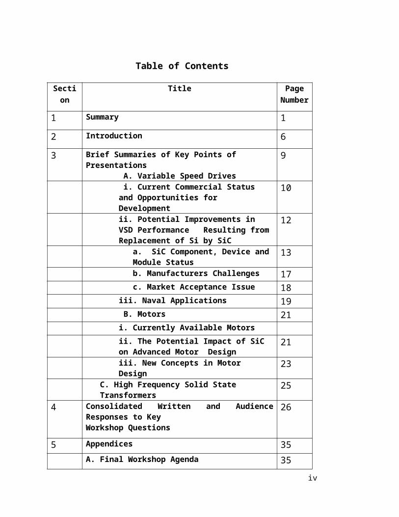
Table of Contents
Section Title Page Number
1 Summary 1
2 Introduction 6
3 Brief Summaries of Key Points of Presentations A. Variable Speed Drives
9
i. Current Commercial Status and Opportunities for Development
10
ii. Potential Improvements in VSD Performance Resulting from Replacement of Si by SiC
12
a. SiC Component, Device and Module Status
13
b. Manufacturers Challenges 17c. Market Acceptance Issue 18
iii. Naval Applications 19 B. Motors 21
i. Currently Available Motorsii. The Potential Impact of SiC on Advanced Motor Design
21
iii. New Concepts in Motor Design 23C. High Frequency Solid State Transformers 25
4 Consolidated Written and Audience Responses to Key Workshop Questions
26
5 Appendices 35A. Final Workshop Agenda 35B. List of Workshop Participants 38C. List of Workshop Presentations 41D. Workshop Participants Comments on Presentations
and Key Questions43
E. Individual Written Responses to Key Questions 54
iii
List of Abbreviations
AC Alternating CurrentDAB Dual Active BridgeDC Direct CurrentDOE Department of EnergyESS Electricity Storage SystemEV Electric VehicleFY Fiscal YearGaN Gallium NitrideGW Giga WattGWh Giga Watt-hourHF High FrequencyHHEV Human Hybrid Electric VehiclesHMW High MegawattHV High VoltageHVDC High Voltage Direct CurrentHV-HF High Voltage High FrequencyHz HertzIGBT Insulated Gate Bipolar TransistorIPM Intelligent Power ModuleskHz kiloHertzkV kilo VoltskVA kilo Volt AmperekW kilo Watt kWh kilo Watt-hourLV Low VoltageMOSFET Metal-Oxide Semiconductor Field-Effect TransistorMV Medium VoltageMVA Mega Volt AmperesMW MegawattMWh Megawatt hourMHz MegaHertzNIST National Institute of Standards and TechnologyOEM Original Equipment ManufacturerPCS Power Conditioning SystemPV PhotovoltaicPIM Power Integrated ModulesR&D Research and Development SECA Solid State Energy Conversion AllianceSi SiliconSiC Silicon CarbideSST Solid-State Transformers
iv
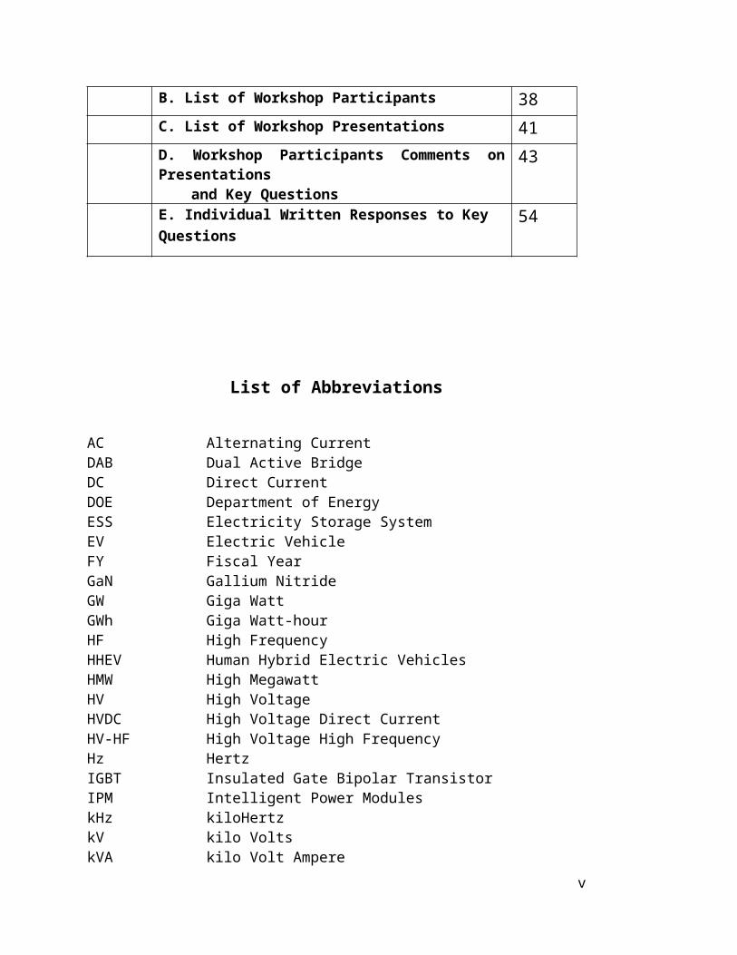
US United StatesUS$ United States DollarsVAC Volts ACVSD Variable Speed DriveWBG Wide Band Gap
v

vi

1. Summary
On April 16-17, 45 invited participants convened at NIST (National Institute of Standards and Technology) headquarters in Gaithersburg, MD from 8am on April 16 through 1 pm on April 17, 2014 to participate in the NIST/DOE Workshop on High-Megawatt (HMW) Variable Speed Drive (VSD) Technology.
The complete set of presentations can be viewed or downloaded at the NIST High Megawatt (HMW) Workshop site at http://www.nist.gov/pml/high_megawatt/2014_workshop.cfm The goal of the workshop was to identify advanced technologies and approaches that have the potential to substantially improve the energy efficiency, performance and cost of megawatt to high-megawatt scale variable speed motor drives used in a wide range of applications. The results of the workshop and the associated follow-on system impact study will be used to define an advanced technology development and manufacturing roadmap for HMW VSD motors.
The major conclusions that can be drawn from the presentations and discussions at this Workshop are that:
Pumps, fans, and compressors make the biggest market for industrial drives. Traction, HHEV (Human Hybrid Electric Vehicles), and wind are growing sectors, as well as small industrial systems. Approximately 14% of the total electricity consumed in the United States flows through large power electric motors (1-50 MW) that are widely used in the COG (Chemical, Oil, and Gas) industry, for example.
VSD driven motors can save 40% electricity demand per motor on average by discarding mechanical throttles to control flow, etc. With 90% adoption of VSD, at least 5% of total electricity consumption in the US could be saved. The cost savings in electricity energy consumption for individual drive owners would be substantial.
While these savings resulting from the installation of currently available VSD are estimated to provide pay-back periods of 2-3 years, many equipment owners and, by implication, their vendors, appear to be reluctant to accept the perceived risk of reliability shortcomings. As a result, they don’t purchase VSD in spite of favorable economics.
SiC-based components offer higher breakdown voltage, faster switching speed, lower switching losses, lighter weight, simpler topology and potentially lower cost. These attributes would improve VSD performance, reliability, and adoption rate.
New solutions enabled by the utilization of SiC in place of Si include:
1

• High-electrical speed Medium Voltage Drives (for multiple pole high torque or high rotational speed motors)
• “Transformer-less” Medium Voltage Drives (“transformer-less” replaces large 60 Hz transformers with small, high frequency transformers integrated within high frequency power electronics)
• Integrated Motor-Drives
Field experience with 1200 V and 1700 V SiC Schottky Diodes and MOSFETS is building up. 10 kV and 15 kV SiC Schottky Diodes and MOSFETs are being demonstrated. Intermediate product offerings of 3.3 and 4.5 kV components are considered by some of the Workshop participants to be important incremental steps in building up the SiC-based field reliability data base.
.Experience over the last decade has demonstrated that the price of SiC-based components has fallen dramatically as product sales volumes have increased. The U. S. Department of Energy (DOE) anticipates that the prices of high voltage (> 4.5 kV) SiC-based components will reach parity with Si-based components on a $/W basis within 5 years.
The Workshop participants were asked to respond to a total of 11 Key Questions during open discussion. In addition, 14 of the 45 participants provided written responses. The questions and selected examples of very representative answers are listed in the following, which are not in any priority order. It is strongly recommended that the reader review the entire sets of responses (see Section 4) to these questions as many other responses might have been chosen.
Key Question 1. What are the benefits and barriers of increased penetration of VSDs (Variable Speed Drives) for HMW (High Megawatt) motors?
BenefitsVSD driven motors can save 40% electricity demand per motor on average by discarding mechanical throttles to control flow, etc.
BarriersThe major barriers most frequently cited are the higher cost of VSD systems, concerns about their reliability, and load current harmonic injection back into the supplying power system.
Key Question 1a. What and why are VSDs used for in HMW Motors today?
VSDs are widely used in large scale industrial applications such as steel rolling mills grinding mills, mine winders, metal industry, lumber industry, traction, pumps, fans, compressors, propulsion, wind power systems, mining conveyors, flywheel energy storage systems, etc.
2

Key Question 1b. What is the pay-back period that would generate strong market interest?
The range of responses was 1-5 years (one response each) but all the other responses were 2-3 (9 responses) years.
Key Question 1c. What are efficiency benefits that would warrant incentives?
The US Navy has estimated that they could save 12-24% of their fuel consumption by converting to hybrid electric drives.
The higher electrical efficiency resulting from the use of VSDs in HVAC systems has led to a requirement for their use in European HVAC installations.
Key Question 2. Are there VSDs/Converters on the market that incorporate SiC and what is the benefit? Specific examples include Mitsubishi products including a 1 MW traction drive and an auxiliary power drive for traction, hybrid modules in MRI systems in health care equipment enable high switching frequency with reduced losses, motor controllers in avionics applications, and SiC power devices are used in many power supplies.
Key Question 2a. Are demonstration projects needed to confirm performance, reliability, and payback period estimates?
All the responders felt strongly that demonstration projects were needed.
Key Question 2b. Is there a large retrofit market for installation of SiC-based VSDs?
In general, the responses to this question were negative. Most of the existing VSDs have been custom designed for their specific application. Another barrier is that Si power devices/drives don’t wear out; their controls become obsolete.
Key Question 2c. Are there specific barriers for HMW applications of SiC for HV-HF?
The major issue is the perceived reliability of SiC components since there is little field data, because of the limited period that the newest, highest capacity SiC devices have been in service (It should be noted that field data reliability is very favorable for the lower voltage <1700 V SiC Schottky diodes that have been in the marketplace for over a decade). As a result, the kind of reliability that many customers demand has not been adequately demonstrated for HMW applications of SiC. Another issue with HV-HF, is high dv/dt, which would mean insulation design can be challenging.
3
Key Question 3. What Advanced VSD/converter performance characteristics are required to achieve system benefits and desired payback estimates?
There were a wide variety of suggestions for this topic: Integration of power system interface (replace transformer) Higher power density which should translate to system level cost saving The Navy perspective:
(1) Demonstrate reduced losses (not the same as converter efficiencies)(2) Demonstrate high frequency (higher than Si) waveforms
Ability of a VSD to ride thru a load short-circuit without damage Reduced cooling and filtering requirements; elimination of input transformers
Key Question 3a. What additional technology and advanced device performance are needed for HMW VSDs (for example which SiC or Si devices type/voltages etc. would be most beneficial)?
There were a wide variety of suggestions for this topic: Packaging and the other elements that go into making a module that exploits
SiC’s characteristics – voltage, frequency and thermal are needed. Dielectrics, potting compounds are included.
Both LV and HV high reliability SiC devices; 3.3 kV and 10 kV MOSFETS SiC at 15kV or 20kV for 2-3 level 15kV rms class drives Raising current rating on SiC MOSFETs for 4-6 kV devices to be competitive
with conventional high speed thyristors 2000-3000 amps average current Higher currents, 1000 amps or higher at 5 kV or above.
Key Question 3b. Are there other technologies needed for HMW drives/converters (passive components, gate drives, sensors, controls, and protection devices – contactors, breakers)?
There were a wide variety of suggestions for this topic. A few representative responses were:
System integration between motor and drive Integration within a high-performance building block Devices are reliable but modules are not reliable enough yet Improved cooling is required, especially for mining equipment
Key Question 3c. What analysis is needed to define the most promising options for HMW VSDs?
There were a wide variety of suggestions for this topic. A few representative responses were:
4
Cost model for overall system with or without SiC for full motor/drive system.
dv/dt issues due to HV-HF being 3 to 10 times larger than silicon How does short circuit requirement impact on-state voltage, and switching
speed SOA, pulse current rating, dynamic thermal impedance, loading, and thermal
limits need to be re-analyzed Volume that will lead to reduced costs. HV SiC module requirements and
costs also need to be included
Key Question 4. What are the most promising motor technologies that could be enabled by WBG VSD?
Suggestions for this topic included:
The Vernier Motor Concept could utilize SiC components Brushless Doubly Fed Machine Motor Concept.
Key Question 5. What are power train integration (and electrical system) approaches that will be enabled by HV-HF power conversion and have maximum system benefit?
There were a wide variety of suggestions for this topic. A few representative responses were:
Transformerless Medium Voltage drives can reduce balance of plant by reducing need for transformer
There are a number of system elements that could be beneficially integrated including grid interface, VSDs, machines, gears
MVDC is a future platform to integrate with High voltage to low voltage DC transformer as core element
HVAC systems and shipboard applications - lower size, weight, cabling, transformer magnetics
Key Question 6. What are applications that can use SST? What other functions are needed beyond what a transformer can provide to serve as an early adopter until cost is comparable to transformers.
There were a wide variety of suggestions for this topic. A few representative responses were:
SST can provide MV DC port on transformer for storage MV DC distribution can benefit from the isolated DC/DC converter portion of
an SST
5
Solid state transformer for traction application reduces size and weight Solar generators can raise voltage on LV side within HF conversion stage
rather than an LF transformer For Microgrid interconnection SST can provide flow control and DC ports SST applications for power train integration
6
2. Introduction
On April 16-17, 45 invited participants convened at NIST (National Institute of Standards and Technology) headquarters in Gaithersburg, MD from 8am on April 16 through 1pm on April 17, 2014 to participate in the NIST/DOE Workshop on High-Megawatt (HMW) Variable Speed Drive (VSD) Technology.
The goal of the workshop was to identify advanced technologies and approaches that have the potential to substantially improve the energy efficiency, performance and cost of megawatt to high-megawatt scale Variable Speed motor Drives (VSD) used in a wide range of applications. The results of the workshop and the associated follow-on system impact study will be used to define an advanced technology development and manufacturing roadmap for High Megawatt (HMW) VSD motors. The broad spectrum of invited participants represented the medium voltage (MV) drives industry (customers and manufacturers), HMW power electronics industry, government and academia.
Over the last few decades, motors have generally evolved to utilize power electronics-based VSD technology due to the overall system efficiency and performance advantages. However, many HMW motors do not use VSDs due to limitations of available power semiconductors at the higher voltages that make the HMW VSDs more complex, costly, and bulky. Recent advances in high-voltage SiC-based power semiconductors provide the potential to improve the overall size, weight, cost, and performance of HMW Power Conditioning Systems (PCSs) making them more practical for many new applications. If the high-voltage SiC power semiconductors were to enable pervasive use of VSDs for HMW applications, it could account for a significant reduction of total energy usage world-wide. Furthermore, advanced machine technologies including hard and soft magnetics, advanced motor designs, and high speed direct drive approaches might also play a critical role in enabling maximum benefit for a wide range of HMW VSD motor applications.
This workshop was the first step in a process to define an advanced technology development and manufacturing roadmap for HMW VSD motor technology. The workshop identified existing and future HMW VSD motor applications, motors types, and VSD architectures, and defined the potential advantages of advanced power electronics and machine technologies. Representative approaches identified at the workshop and/or contributed directly by the participants will be selected for a follow-on quantitative analysis of the potential benefits of the new technologies. It is anticipated that the results of the follow-on analysis will be presented for discussion at a second HMW VSD technology roadmap workshop and that the results will be used to guide future activities including potential future investment by DOE in wide band-gap (WBG) power electronics and machine technologies for HMW VSD motors.
7
On April 16, 2014, nineteen formal presentations were made by leading experts in five separate sessions. These sessions were titled:
Introduction to HMW PCS Technology Roadmap and HV-HF Power Devices HMW Converters using HV-HF Semiconductors) High Megawatt Motor Application Requirements Motor Concepts and Technology HMW Motor Power Train Integration
The information from the presentations was summarized by topic and presented in Section 3 of the Proceedings. The information was organized as follows:
A. Variable Speed Drives
i. Current Commercial Status and Opportunities for Development
ii. Potential Improvements in VSD Performance Resulting from Replacement of Si by SiC
a. SiC Component, Device and Module Status b. Manufacturers Challenges c. Market Acceptance Issue
iii. Naval Applications
B. Motors
i. Currently Available Motors ii. The Potential Impact of SiC on Advanced Motor Design
iii. New Concepts in Motor Design
C. High Frequency Solid State Transformers
Each presentation session was followed by a discussion period. Summarized comments by the participants were documented. These summaries were presented to the participants at the opening session on April 17, 2014 in preparation for a discussion by the audience to 11 Key Questions that will help in planning the follow-on session. Comments by audience members are summarized in Appendix D of the Proceedings. At the end of the Workshop, participants were invited to submit written comments. Fourteen did so. The individual written responses to those Key Questions, which are listed below, are presented in Appendix E of the Proceedings.
Question 1.What are the benefits and barriers of increased penetration of VSDs (Variable Speed Drives) for HMW (High Megawatt) motors?
Question 1a. What and why are VSDs used for HMW Motors today?Question 1b. What is the pay-back period that would generate strong market interest?
8

Question 1c. What are efficiency benefits that would warrant incentives?
Question 2. Are there VSDs/Converters on the market that incorporate SiC and what is the benefit?
Question 2a. Are demonstration projects needed to confirm performance, reliability, and payback period estimates? Question 2b. Is there a large retrofit market for installation of SiC-based VSDs?Question 2c. Are there specific barriers for HMW applications of SiC for HV-HF?
Question 3. What Advanced VSD/converter performance characteristics are required to achieve system benefits and desired payback estimates?
Question 3a. What additional technology and advanced device performance are needed for HMW VSDs (for example which SiC or Si devices, type/voltages etc. would be most beneficial)?Question 3b. Are there other technologies needed for HMW drive/converters (passives components, gate drives, sensors, controls, and protection devices – contactors, breakers)?Question 3c. What analysis is needed to define the most promising options for HMW VSDs?
Question 4. What are advanced motor technologies that could be enabled by WBG VSD?
Question 5. What are power train integration and machine technology integration opportunities?
Question 6. What are applications that can use SST? What other functions are needed beyond what a transformer can provide to serve as an early adopter until cost is comparable to transformers?
9
3. Brief Summaries of Key Points of Presentations
The Workshop, which convened on April 16, 2014, began with the following four opening presentations:
Al Hefner (NIST) – Introduction to HMW PCS Technology Roadmap and HV-HF Power DevicesAnant Agarwal (US DOE) – Introduction to DOE EERE/AMO Wide Bandgap Power Electronics Programs Ravi Raju (GE) – HV-HF SiC Power Conversion OverviewTom Lipo (University of Wisconsin - Madison) – Overview of Advanced HMW Motors and Drives
These opening presentations were followed by five sessions during which the following presentations that are listed in the next paragraph were made. At the end of the presentations in each session, the speakers convened as a panel for a 30 minute period to respond to audience questions. Summaries of these sessions were prepared by staff and presented to Workshop participants prior to open discussion during which the audience was asked to provide responses to Key Questions developed by the Workshop organizers. (Please see Section 4 for questions and responses):
HMW Converters using HV-HF Semiconductors (Chair: Ravi Raju, GE)Ravi Raju (GE Global Research) Waqas Arshad (ABB) Shashank Krishnamurthy (United Technologies Research Center) Fred Wang (University of Tennessee - Knoxville)
High Megawatt Motor Application Requirements (Chair: John Amy, US Navy)John Amy (U.S. Navy) Sean Huang (Exxon)Rajib Datta (GE) Subhashish Bhattacharya (North Carolina State University)
Motor Concepts and Technology (Chair: Tom Lipo, University of Wisconsin - Madison)
Tom Lipo (University of Wisconsin - Madison) Robert Chin (ABB) Longya Xu (Ohio State University)
HMW Motor Power Train Integration (Chair: Waqas Arshad (ABB))Veli-Matti Leppanen (ABB)Rob Cuzner (DRS) Bill Giewont (Vacon) Peter Liu (Toshiba)
An integrated topical summary of the presentations was developed and follows. It is divided into the following sections
10

A. VSD (Variable Speed Drives) i. Current Commercial Status of and Opportunities for Development
ii. Potential Improvements in VSD Performance Resulting from Replacement of Si by SiC
a. SiC Component, Device and Module Statusb. Manufacturers Challengesc. Market Acceptance Issue
iii. Naval Applications
B. Motors
i. Currently Available Motorsii. The Potential Impact of SiC on Advanced Motor Design iii. New Concepts in Motor Design
C. High Frequency Solid State Transformers -- Opportunities for Advanced Transformer Development
Ai. Current Commercial Status of and Drivers for Development of VSD (Variable Speed Drives)
Approximately 14% of the total electricity consumed in the United States flows through large power electric motors (1-50 MW) widely used in COG (Chemical, Oil, and Gas) industry. Applications include hydrogen gas compressors (hydro-cracking in oil refineries), booster stations in natural gas pipelines, high density polypropylene extruders, ethylene gas compressors, sea water injection and lift, etc. Steam turbines, gas turbines and diesel engines for off-shore applications that typically operate at 20-25% efficiency are being replaced by large electric motors to reduce both fuel consumption and CO2 emissions. (Agarwal) Pumps, fans, and compressors make the biggest market for industrial drives. Traction and HHEV are growing sectors, as well as small industrial systems. Installed wind capacity in the world will reach 350 GW in 2014. Installation run rate was ca. 40 GW per year in 2009 – 2013. DC grids for wind farm collection as well as on board distribution in marine call for > 10 kV converter technologies (Leppanen)
VSD driven motors save 40% electricity per motor on an average compared to directly connected motors operating at full speed by discarding mechanical throttles that are used to control flow. That is equivalent to at least a 5% savings in the total electricity consumed in the US by 90% adoption of VSDs. (Agarwal)
The power semiconductor module market is more than $5 Billion USD and is spread across many market segments.
11

Power semiconductor module market 2012
Millions, US$ % Power Train Related
Industrial motor drives 2468 46.7Consumer 562Traction 535 10.1Wind and Hydro 369 7.0Power Supply 332Solar 235EV 196 3.7Industrial heating and welding 173HHEV 50 0.9Grid Infrastructure 15Other 354Total 5289Power train related 3618 68.4%
(Leppanen)
Device Expenditure Distribution, 2012 Millions, US$Thyristor-Diode 538MOSFET 152IGBT 2390PIM 449IPM 1760Total 5289
(Leppanen)
Oil and gas production applications of high‐megawatt VSD primarily involve starting gas turbine generators, operating compressors and pumps, and transmitting/distributing electric power, subsea and offshore. Critical requirements include safety, reliability and availability, performance and cost. (Huang)
MV (Medium Voltage) motors are used typically in critical processes including steel mills, cement kilns, air-handling, compressors, pumps etc. Only 30-40% of these motors are driven by VSDs. (Bhattacharya)
MVD (Medium Voltage Drives) Market Penetration - Going up in last 15 years, especially last five years, strong demand from oil and gas, mining. (Liu)
Because of the higher efficiency of motors with VSD drives, these drives are now required for HVAC systems in some European countries. [This efficiency standard is
12

not required in the US.] HVAC (chiller and heat pump) units sold in 2012 in US totaled:
<20 hp Scroll compressor - 4.5 million20-200 hp Screw compressor – 1 million Need VSD200-2000 hp Centrifugal Compressor – 2000 Screw compressors require VSDs to operate. Centrifugal compressors require mechanical plus VSD drives. (Krisnamurthy)
VSD manufacturers making presentations at the Workshop included ABB, GE, Toshiba, United Technologies, and Vacon. ABB manufactures LV and HV drives. (Chin) GE manufactures LV and HV drives for numerous industries including multiple industrial applications including traction, healthcare COG, compression, etc. (Datta) Toshiba manufactures LV drives, MV drives, and OEM Drives (Liu). United Technologies manufactures drives for multiple industries including HVAC. (Krisnamurthy). Vacon is the world’s largest company in terms of revenues and product selection that concentrates entirely on AC drives including compact AC, multipurpose AC, and industrial AC drives. (Giewont)
Aii. Potential Improvements in VSD Performance Resulting from Replacement of Si by SiC
The replacement of Si with SiC power electronic components, devices, and modules offers enhanced performance including operation at higher voltage higher switching frequency, and higher temperature. The challenge is that these items are being produced at relatively low volumes at this time which results in higher prices than the Si-based items that they are tended to replace. Prices have been coming down as production increases but DOE anticipates that breakeven pricing is likely to be achieved within five years. Current pricing has limited utilization to relatively high value applications to date.
The next three sub-sections of these Proceedings review information presented that is relevant to:
a. SiC Component, Device and Module Statusb. Manufacturers Challengesc. Market Acceptance Issues
Aii.a. SiC Component, Device and Module Status
13

The vision for the DOE Strategy for their Next Generation Power Electronics Initiative (Power America) is to capture opportunities for U.S. manufacturing leadership in R&D and manufacturing of SiC- and GaN-based Wide Bandgap Power (WBG) Devices on 150 mm substrates and identify/demonstrate high value added applications in Power Electronics. (Agarwal)
The DOE SECA (Solid State Energy Conversion Alliance) program has a goal for the cost of -$40-100/kW for a 300 MW PCS. These Power Conditioning Systems (PCS) will be used to economically convert to/from 60 Hz AC for interconnection of renewable energy, electric storage, and PEVs to support market penetration of distributed generation. “Smart Grid Interconnection Standards” are required for devices to be a utility-controlled operational asset and enable high penetration that will provide:
• Dispatchable real and reactive power • Acceptable ramp-rates to mitigate renewable intermittency • Accommodate faults faster, without cascading area-wide events• Voltage/frequency regulation and utility-controlled islanding (Hefner)
New semiconductor devices that utilize WBG materials have extended the application range to higher power levels for motor control, traction, and grid PCS. Emerging technology, including SiC Schottky diodes and MOSFETs, and GaN, allows higher speed switching for power supplies and motor control. In the future it is anticipated that HV-HF SiC-based MOSFET, PiN diode, Schottky, and IGBT items will enable 15-kV, 20-kHz switch-mode power conversion. (Hefner)
There are a number of advantages that may be obtained from replacement of Si- based items with SiC-based items. These include:
Simplification of converter topology Allow Integrated Drive system configuration Allow for high power density, high temperature, harsh environment operation
(Datta)
The following chart summarizes the needs that various potential application spaces have for high current, high performance cost competitive modules:
kVA V A IGBT Volt SiC Volt Benefits
Wind
Doubly-fed Induction Gen
750 690 1331 1700V 1700VHigher efficiency Higher switching frequency (Fsw: 5-->20kHz) Better fault handling
Synchronous Gen 3000 960 3827 1700V 1700V
Solar Single Stage 1000 480 2552 1200V /1700V 1700V SiC Higher efficiency
Higher switching
14

frequency (Fsw: 5-->20kHz) Better fault handling
Traction 1000 1500 816 2500V 2500V Higher Power Density
HealthcareMR 1000 1000 1000 1200V
1200V/2500V
Very High switching frequency (Fsw: 20kHZ-->60kHz) Higher Power Density
MV Drives
3L 2500 3300 928 4500V1700V/2500V Series
Higher Power Density Higher switching frequency (Fsw: 1-->10kHz)
Cascade H-bridge 417 953 928 1200V 1200V
3L 5000 6600 928 4500V series
1700V/2500V series
Cascade H-bridge 556 1270 928 1200V 1700V
(Datta)
The use of SiC in place of Si in power electronics devices was discussed by John Amy based on a 2007 paper that he co-authored. These include:
• SiC devices will have 5-30 times higher breakdown voltage than Si allowing the use of single devices vs. series devices for practical Naval high voltage applications.
• Higher breakdown voltage of SiC allows thinner devices and increased doping levels, thereby reducing the on-state resistance. On-state resistance (Ron) will be ~300 times lower with SiC than Si.
• SiC has higher thermal conductivity which reduces thermal resistance, Rth-jc. This can be seen to be a ratio of 3.27 higher for SiC.
• SiC can operate at higher temperatures (up to 600°C).• Forward and reverse characteristics of SiC do not vary with temperature as
much as Si, therefore SiC devices are expected to be more stable.• SiC devices will have better reverse recovery characteristics, thereby reducing
switching losses vs. Si devices.• SiC is extremely radiation hard due to the wider bandgap. (Amy)
15

SiC characteristics provide new attributes for converter designers to include in their systems:
• Increased Blocking Voltage– Fewer devices not significant in themselves– Simpler topology, fewer gate drives, etc. are significant
• Increased Switching Frequency (4x)– Reduced size/weight of passive components– 4% volume / 5% weight reduction
• Reduced conduction losses– Switching devices ~56% of converter losses– 4x reduction in conduction losses -> 21% reduction in converter losses– 1% volume / 1.5% weight reduction
• Reduced switching losses– Switching devices ~56% of converter losses– Competing objectives: SiC less loss per switch event, but switching
much more often -> 12% reduction in converter losses– No significant change in converter size/weight (Amy)
SiC enables higher speed and voltage. Other attributes of emerging SiC and GaN Schottky diodes and MOSFETs, include higher speed for power supplies and motor control. (Hefner)
New solutions enabling the utilization of SiC in place of Si include:
• High-speed Medium Voltage Drives• Simpler 2L or 3L topologies using high switching frequency of
SiC devices can provide simpler solution• “Transformer-less” Medium Voltage Drives
• MV drives typically require a large transformer at the input for voltage scaling and isolation
• Possible to significantly reduce drive footprint and potential cost by using high frequency transformer (from 60Hz to 60 kHz)
• Integrated Motor-Drive• Integration of power electronics with machines at low and
medium power • Substantially increase power density, particularly in mobile
applications• High temperature capability of SiC can be effectively used to
minimize cooling loops (Datta)
Potential customer benefits resulting from utilization of WBG materials include:
Cost/efficiency-Reduced THD (line/load), reduced magnetics line/load), reduced thermal management costs, REDUCED OVERALL SYTEM COSTS- (expected)
16

Reliability –reduced number of devices, cosmic ray derating <Si (Giewont)
According to CREE, the potential future availability of 10-15 kV components (which are very desirable from a performance standpoint) is as follows:
10 kV SiC MOSFETs - nearest to commercial availability 15 kV SiC MOSFETs – now being demonstrated 15 kV and higher SiC IGBTs - demonstrated but need to establish reliability
An alternative approach to the use of a 10 kV SiC module is to combine six 1.7 kV hybrid module (SiC diodes and Si switches) building blocks in place of a single 10 kV SiC module. This approach is currently in the demonstration phase. Both 1.7 kV Si and SiC components are currently commercially available. The advantages and disadvantages of each approach are summarized below.
10 kV SiC module 6 x 1.7 kV with Si switch and SiC diode
Advantages Disadvantages Advantages DisadvantagesReduced number of parts
MOSFETs high Rdson @ higher temp
Possibly more efficient?
Higher parts count
Possibly more power dense
GBT too high Vo (~4 Volts )
Cheaper devices More complex controls
No need for balancing
Expensive Wide choice of suppliers
Less control complexity
Few suppliers
(Raju)
Currently available Si-based MV drives face challenges due to their operating regime: MV semiconductors => high losses =>limits switching frequency & power
throughput & grid harmonics MV => high energy => limits size of passives=> shorter time constant
=>dynamic operation, requires fast action
These MV drives are challenged by: Low switching frequency => low control bandwidth => difficult to meet
control objectives High losses => Limits power throughput (Arshad)
High power can be achieved by increasing the voltage. The Advantages and Disadvantages of increasing voltage are:
Disadvantages Advantages. High dv/dtMore complex insulation concept
Smaller cross sectional area of cable- Cost effective drive set-up-
17

Less familiarity of plant electricians and drive service personnel with medium voltage levels
Circuit breakers of lower current rating effective drive setup
Lower rms current, lower conduction losses
- Higher efficiency(Arshad)
Benefits of SiC to drives include: SiC switching losses are very flat with switching frequency:
Higher output power compared to Si at f_sw = const. Crossover point above critical switching frequency (LV) Si: P_losses = P_cond + P_sw
(40%) (60%) SiC: P_losses=P_cond + P_sw
(60%) (40%) (Arshad)
For MV drives• SiC Diode technology brings a definite benefit in reducing the turn-on
switching losses of the semiconductor switch. • ABB see the hybrid Si+SiC power modules as a promising entry point
for SiC in MW applications, but limited by the Si operating temperature
• Full SiC modules show an additional reduction in losses compared to hybrid technology, but are limited mainly by their low current rating and over voltages due to the fast unipolar SiC switch (Arshad)
Aii.b. Manufacturers Challenges
A long list of items were identified that required additional R&D work to resolve.The issues most frequently cited are:
• dv/dt• EMI• Short Circuit Capability
IGBTs are typically rated for > 10 us SC (Short Circuit) withstand time but SiC chips with same ‘nameplate’ current rating are smaller area and thinner voltage blocking layers than Silicon IGBT chips and therefore have
- lower thermal capacity- lower SC withstand capability - need faster protection (Raju)
One perspective on HMW VSD is that it must face the following issues:
Application driven
18

Power density Integrated approach (motor and drive) ”Performance” optimization (?) vs Cost Reliability Responsibilities/ownership (Chin)
Si-based systems have performed in well established markets. For example, in the Medium-to-High Power market for DC-DC converters, Si IGBTs (1700 - 3300 V) are quite efficient with resonant switching. In the inverter market SiC MOSFETs start to become competitive with Si IGBTs even with ~ ½ chip area and and moderate switching frequencies (<5 kHz) (Raju)
Among the R&D demands, SiC based- systems (R&D demands)• Power modules – reduced parasitic inductances, suitable for high
switching transients• Topologies – take full advantage of SiC device properties• Layout (mechanical integration) – targeting higher blocking voltage.
This would require larger insulation distances while having to keep the parasitic inductances low to avoid fast switching over voltages.
• Passive components – filters, magnetics, capacitors need to be optimized to fully benefit from the SiC performance
• Gate Drives – fast transients combined with high voltage and expected paralleling of many semiconductor devices. New protection schemes needed?
• Control algorithms – faster switching frequencies• Cooling – higher temperature operation combined with higher current
densities and increased integration require innovative cooling technologies (Arshad)
Other areas identified as requiring further development to meet market demands were
Differential and Common Mode EMI (>50 kV/us) Insulation systems (cable, motors, transformers, inductors, Low inductance
BUS) Measurement devices susceptibility to du/dt High Temperature Packaging (Giewont) Silicone encapsulant temperature stability (Giewont) Sinter tie attach and Ribbon bonding (Giewont)
Aiic. Market Acceptance Issues
Reliability and Cost were most frequently mentioned as the most important market acceptance issues for SiC based items One of the greatest impediments to utilization of SiC components in critical services is the perception that there is not enough field data in high voltage service to provide the confidence that is needed by customers to
19

provide assurance that they will not experience unexpected downtime for large equipment.
Specific reliability issues identified were:
At the system level, reliability has to be assessed in order to understand the critical failure mechanisms and sources of stress when incorporating novel SiC technologies (Arshad)
Customers looking for 20 year life/ 8 year MTBF (Giewont) Accurate models for predicting reliability of the design phase (Giewont) Real-time monitoring of the power device fatigue to address reliability/up-
time (Giewont)
Aiii. Naval Applications
Naval applications were identified as a unique market for high performance components, particularly with the US Navy plans to move to all-electric ships in the future. In addition, this market is willing to pay a premium for improved performance to meet specific mission requirements. Among the systems suggested for shipboard applications were:
• Frequency Converters• Electric propulsion drives• Electromagnetic aircraft launching and recovery systems• Point-of-use power converters for electric distribution systems• Integrated power distribution systems• Auxiliary motors and drives• High energy weapon systems• Pulse power systems• Energy storage systems (Amy)
Potential device applications included:• 10kV is a useful blocking voltage rating• Simple topologies considered with standard de-rating practices
– Single device H bridge– Series (2) devices H bridge– Three level
• Current ratings must increase.– 75-100A Rating for 320kW application– 150-200A Rating for 1200kW application (Amy)
There are specific criteria for the individual attributes that High HP VSD drives offer that must be met in naval applications:
Power Densityo For retro-fit solutions, must fit into the existing spaceo For new platforms space is limited
20
Motor Loado Permanent Magnet Motor is more power denseo Low leakage inductance
Good from a power density perspective Bad from the perspective that it drives high power
quality requirements into the motoro Voltage level
High voltage drives significant risk and qualification costs
Insulation system needs to be over-designed for the rating
Lower voltage through >3 phase or multi-level VSD strategies puts cost and reliability burden on the VSD
Ship Service Power Interface• Must meet high input power quality (IHD<3%)• Must withstand large input voltage fluctuations without
impacting down-stream processes• Multi-Pulse Transformer-Rectifier solution impacts power
density• Active front-end solution adds significantly to VSD cost
and increases the conducted and radiated EMI (which must be mitigated)
Environmento Shock/Vibration mitigation requires mil-hardened design
or “cocooning” of commercial solutionso Temperature usually drives the VSD design more than
the motor designo Availability of Water cooling
Drives need for “cocooning” is to provide a self-contained controllable environment
A water-cooled motor is a costly, custom design and imposes requirement on shipboard auxiliaries that impacts every aspect of shipboard system design and CONOPS (Cuzner)
Serviceabilityo Obsolescence of replacement partso Identification of the Lowest Replaceable Unit (LRU)o Modular multi-phase VSD designs are desirable but
impose significant cost and reduce power densityo Fault tolerant VSD and motor combination a pluso VSD MTBF becomes an unexpected cost
Often missed in the proposal stage Must be verifiable in terms of existing norms
21
o The Navy should adopt new paradigms that allow for technology advancements in how reliability is managed
Costo External pressure to reduce spending favors COTS
solutions and overshadows compliance during procurement phase
o COTS solutions usually fall short in meeting shipboard requirements
o VSD’s often get a black eye because of high integration costs
o Lack of system integration by VSD suppliero Lack of Navy experience with power conversion o Unexpected and missed requirements (Cuzner)
The development goals for shipboard systems are summarized below:
Development of MIL compliance, platform based drives family(?) to provide solutions which are cost effective and address the obsolescence issues for the Navy and DRS-PCT.
• Utilizing the latest power electronics/control technologies
• Utilizing next generation power semiconductor modules• Extend the technology to SiC
Develop a technology platform in hardware and software for a high level of modularity and use common parts for cost reduction. (Cuzner)
Next Generation shipboard IPS challenges include: MVDC (10-20kVDC) Platform:
o High voltage motor vs. cost of Solid State Transformer to reduce motor voltage
o Multi-Level VSD topologieso Maximize device voltage rating vs. allowable switching
frequency (>5kHz is desirable) MVAC (13.8kVAC) Platform:
o Focus technology on transformer-rectifier front end design
o With appropriate focus on AC interfaces, risks in VSD topology can be reduced
Legacy (450VAC, 4160VAC) Platforms:o Ship service feed compatibility
Cost vs. compliance vs. performance (Cuzner)
B. Motors
22

Bi. Currently Available Motors
Megawatt-size motors used in industry fall into three categories. The Constant Speed category is dominated by Induction Motors which capture ~90% of that market. Synchronous Motors become competitive beyond 3-5 MW. The Variable Speed Motors category is dominated by Induction Motors. There is significant use of High MW Synchronous Motors. PM (Permanent Magnet (using Nd2Fe14B) Motor) use is minimal. (Lipo 1)
High-power motors (375 kW to 100 MW) comprise only 0.027% by number of the installed motor capacity but consume 23% of total global motor energy. In 2011, only 13% of MV (Medium Voltage) motors were fed by a drive. The other 87% are directly connected to a grid. Of the equipment used with drives-40% are used with pumps 30% with fans, a total of 15% with compressors and conveyors and a total of 15% with rolling mills, mixers, test beds, propulsion winders, etc. (Arshad)
Motor manufacturers making presentations at the Workshop included ABB, GE. and Toshiba.
ABB offers a wide variety of motors: Complete product offering from sub-fractional HP up to 70 MW
LV, MV and HV induction motors and generators Synchronous and permanent magnet motors and
generators DC motors, servomotors, gear motors Mechanical power transmission products
Asynchronous motors Synchronous motor (PM and reluctance) Field-wounded synchronus machines Synchronous and induction generator (Chin)
GE offers a wide variety of motors: High Torque –up to 20 MW below 400 rpm Induction – conventional speed up to 80 MW Synchronous – up to 100 MW Explosion Proof-up to 6 MW Marinized – up to 18 MW Induction High Speed –up to 18,000 rpm (Datta)
GE also offers an Integrated Compressor Line Direct-drive high-speed Induction Motor / Permanent Magnet motor High fundamental frequency capability of MV drive using novel multi-level
converter technology
Toshiba manufactures LV (Low Voltage) motors, HV (High Voltage) motors and motors for HEV (Hybrid Electric Vehicles). (Liu)
23

MV motors are used typically in critical processes – steel mills, cement kilns, air-handling, compressors, pumps. etc. Reliability is key; downtime is allowed with concept of “modular replacement” possible by semi-skilled people. (Bhattacharya)
There are a number of challenging specifications that must be met Higher voltage Higher power Heavily customized design Footprint, frame, cooling….except for power module
(Liu)
Bii. The Potential Impact of SiC on Advanced Motor Design
There are a number of motors operating at high electrical frequencies. Examples of motors operating at high electrical frequencies are high speed motors used in oil and gas compressors at 15,000 rpm, 5MW, 4160V and a new class of machines with high electrical frequency, high pole count, and electromagnetic gears. (Raju)
1-50 MW class motors can be reduced in size by 5x using high-voltage, high-frequency SiC based Variable Speed Drives (VSDs). In COG DD high rpm applications, these motors would be 3X smaller and cheaper. (Agarwal)
Wide Band Gap devices offer the following potential benefits for electrical machines
WBG Device Attributes Benefit for Design of Electrical Machines
High Voltage QuestionableHigh Efficiency Questionable
High Temperature QuestionableHigh Switching Frequency Significant
High Fundamental Frequency Significant(Lipo 1)
WBG devices offer a number of potential benefits including Benefits to the “Big Three”
• A New Motor Side Filter Could Result in Nearly Zero THD Motor Voltage Waveforms
• Negligible Stator Copper and Iron Loss Due to Impressed Harmonics• Possibility of Reduced Magnetics Line Side Filter, Line Side Transformer
(Lipo 1)
24
However, there are also downsides that must be considered:• Increased Differential and Common Mode EMI• Bearing Current Issues• Insulation Degradation (Lipo 1)
There are other machines capable of megawatt ratings• Switched (Variable) Reluctance Motor• Synchronous Reluctance Motor• PM Assisted Synchronous Reluctance Motor• Spoke Type PM Motor• Switched Flux Motor• Transverse Flux Motor• Vernier Motor (Lipo 1)
The following approaches to extending the boundaries of machines are possible: High Speed Machines
o Compact Turbine Driven Power Sourceo Energy Storage Systems
Low Speed Machineso Directly Driven Wind Turbineso Ocean and Tidal Wave Machines
High Temperature Machines (and Drives)o Compact Mechanical Power Sourceso Switching Devices in the Motor Frame
HT Superconducting Machines (Lipo 1)
There are a number of potential approaches to improving high switching-speed performance of WBG in motor drives
Interference between upper & lower switches (cross talk)o Short-through current causes turn-on energy loss increase, tested up to
19% and dv/dt reduction by 10% o Spurious negative gate voltage beyond required range
Interaction between PWM inverter & induction motoro Switching energy loss increased by 32%o Switching time increased by 42% during turn-on and doubled during
turn-off (Wang)
Utilization of WBG devices in PWM motor drives can be improved by Active gate driver circuitry for cross talk suppression Consider motor load characteristics in the design and operation of
PWM inverter Integrated design/operation methodology (Wang)
iii. New Concepts in Motor Design
25

New concepts in advanced motor design were discussed by Tom Lipo and Longyu Xu.
Lipo discussed the Permanent Magnet (PM) Vernier Motor• The torque producing capability of a PM Vernier motor can
exceed that of a conventional motor by 2-3 times with a power factor of 0.82
• For a 4 Pole Vernier to reach 1800 RPM requires a 300 Hz Supply
• A Ferrite PM Vernier Motor having the same size as a conventional Rare Earth PM motor, but with better efficiency, has been demonstrated using FEM (Lipo 2)
Xu discussed the concept of a Brushless Doubly Fed Machine Conceptual Fields and Moving Modulars Features and Potentials
o Dual Stator Windings-Power and control power windings
o Dual Stator Windings – HV and LV windingso Current Free Rotor-No winding,no brushes/slip
ringsand no PMo Modular Rotor Segments-easy to make and multiply
with much reduced cost
C. High Frequency Solid State Transformers
GE carried out a Wide Bandgap Semiconductor Technology (WBST) High Power Electronics (HPE) program for DARPA/ONR to develop and demonstrate advanced Solid State Transformers using 10 kV, 120 A SiC half-bridge power modules. Under the Base Program a 1 MVA, single phase, 13.8 kVac/ 450 Vac solid-state transformer was developed (2007-2009) and tested at full power (2010) at NSWC Philadelphia. Under the follow-on Option Program a 1 MW, 4.16 kVac, 3 phase / 1000 Vdc converter with 1/3rd volume, and 1/10th weight of an existing transformer-rectifier was developed. It is being tested at CAPS-FSU. Both projects use 10 kV SiC devices and modules from Cree/ Powerex and high frequency transformers from IAP, Los Alamos, and Dynapower. (Raju)
Potential applications for Solid State Transformers include 16.7 Hz locomotive application activities (Raju) Arrangement for offshore and onshore wind integration to
HVDC by solid state transformer or Dual Active Bridge (DAB). High power density DAB inside each of the large wind turbines
will reduce the size of the offshore platform structure. Hence cost will reduce (Bhattacharya)
26

At low voltage, weight reduction with electronic transformers and use of high efficiency low voltage motors at medium voltage- input filter area reduction, higher compressor speeds (Krisnamurthy)
27

4. Consolidated Written and Audience Responses to Key Workshop Questions
Question 1.What are benefits and barriers of increased penetration of VSDs (Variable Speed Drives) for HMW (High Megawatt) motors?
BenefitsVSD driven motors can save 40% electricity demand per motor on average by discarding mechanical throttles to control flow, etc. With 90% adoption of VSDs, at least 5% of total electricity consumption in US could be saved. The cost savings in electricity energy consumption for individual drive owners would be substantial.
BarriersThe major barriers most frequently cited are the higher cost of VSD systems, concerns about their reliability, and load current harmonic injection back into the supplying power system. One specific comment was that drive owners want greater than 20 year life and 8 year MTBF.
Question 1a. What and why are VSDs used for HMW Motors today?
VSDs are widely used in large scale industrial applications such as steel rolling mills, grinding mills, mine winders, metal industry, lumber industry, traction, pumps, fans, compressors, propulsion, wind power systems, mining conveyors, flywheel energy storage systems, etc. Applications of high‐megawatt VSDs in the chemical, oil, and gas industries primarily involve starting gas turbine generators, operating compressors and pumps, and transmitting/distributing electric power, both subsea and offshore.
Question 1b. What is the pay-back period that would generate strong market interest?
The range of responses was 1-5 years (one each) but all the other responses (9) were 2-3 years. In the long term, VSD selection must be the low cost solution to capture a dominant market share, but in the short term, functionality benefits might drive early adoption
Question 1c. What are efficiency benefits that would warrant incentives?
The US Navy has estimated that they could save 12-24% of their fuel consumption by converting to hybrid electric drives.
The higher electrical efficiency resulting from the use of VSDs in HVAC systems has led to a requirement for their use in European HVAC installations.
28

Question 2. Are there VSDs/Converters on the market that incorporate SiC and what is benefit? Power semiconductors are the key enabler to new topology. The last revolution was IGBT. The next revolution is anticipated to be SiC HV-HF. SiC provides:
Higher voltage, faster speed, lighter weight, lower cost Switching speed is key limitation for medium voltage drives – without high
speed, must find other method For Medium voltage drives - SiC diode gives definite benefit (hybrid module)
- 40 % improved switching loss. Simpler topology, reliability, size/weight, regeneration, higher frequency
gives benefits to passives, smaller, less distortion Because of the WBG structure of SiC, it is 100x better than Si in cosmic-ray
situations. That is a major problem with mining at elevations >20000 feet. At this level the Si power devices need to be de-rated because of cosmic-ray and air density.
Specific examples include Mitsubishi products including a 1 MW traction drive and an auxiliary power drive for traction, hybrid modules in MRI systems in health care equipment to enable high switching frequency with reduced losses, and motor controllers in avionics applications. SiC power devices are used in many power supplies.
Question 2a. Are demonstration projects needed to confirm performance, reliability, and payback period estimates?
All the responders felt that demonstration projects were needed. The reasons cited were both technical and practical. Practical issues included the following:
Conservative customers need to be convinced. They may not like being an early adopter.
Nobody wants to be the first application/reference. Absolutely, without it, it will be difficult to show the disruptive nature of the
technology.
There were also several recommendations for very specific demonstration projects: Demonstrate MV directly connected front-ends. Demonstrate mitigation of switching effects - common
mode/negative sequence currents, EMI, dv/dt Demo projects must be realistic and combine high density e.g. 4
MW/cu. meter, with 30,000 hour lifetime for drives and converters.
DOD needs to have a demo program that uses a 20 kV DC link and 13.8 kV output.
YES, required for military applications
29

Yes on MW with SST-based DC-DC transformer with galvanic isolation
Retrofit existing MV motors with MV drives to demonstrate efficiency gains and control improvements
Design new motor and drive system for application with goal for overall size, weight and system cost improvements
Select demo projects that identify early adopters and yet would appeal to a broad user base.
Question 2b. Is there a large retrofit market for installation of SiC-based VSD?
In general, the responses to this question were negative. Most of the existing VSDs have been custom designed for their specific application. The concept of a “drop-in” drive replacement market is therefore unlikely. Another barrier is that Si power devices/drive don’t wear out; their controls become obsolete
Question 2c. Are there specific barriers for HMW applications of SiC for HV-HF?
The major issue is the perceived reliability of SiC components since there is little field data, because of the limited period that the newest, highest capacity SiC devices have been in service. As a result, the kind of reliability that many customers demand has not been adequately demonstrated. Another issue with HV-HF, is high dv/dt, which would mean insulation design can be challenging. Other issues that were noted were:
protection and qualification for direct MV connection, the limited number of suppliers, the lack of package standardization reliability and MTBF for SiC compared to conventional 9 kV
thyristors and 6 kV IGBTs short circuit withstand e.g. 50 kA is important requirement lack of packaging knowledge to take effective advantages of high
temperature properties of WBG devices common mode issues at high switching frequencies
Question 3. What Advanced VSD/converter performance characteristics are required to achieve system benefits and desired payback estimates?
There were a wide variety of suggestions for this topic: Need switch mode power conversion system that is cheaper than no VSD Define todays function specs so retrofit would not change motor requirements. Integration of power system interface (replace transformer) Use less expensive motor (insulation, rare earth) Higher power density which should translate to system level cost saving Performance in terms of current/torque control The Navy perspective:
30

(1) Demonstrate reduced losses (not the same as converter efficiencies)(2) Demonstrate high frequency (higher than Si) wave forms
Increased Fgas to reduce size and cost of passives Slew rate of VSDs in going from full-speed forward to full-speed reverse is an
essential and limiting performance characteristic for a bidirectional drive. Ability of a VSD to ride thru a load short-circuit without damage WBG VSD should operate at higher voltage, temperature, and switching
frequencies as compared to Silicon VSDs. Reduced cooling and filtering requirements. Elimination of input
transformers. Easier to shutdown with VSD than mechanical
Question 3a. What additional technology and advanced device performance are needed for HMW VSDs (for example which SiC or Si devices type/voltages etc. would be most beneficial)?
There were a wide variety of suggestions for this topic: Packaging and the other elements that go into making a module that exploits
SiC’s characteristics – voltage, frequency and thermal are needed. Dielectrics, potting compounds are included.
Insulation systems, HV passive (L.C.) technology. Device packaging. High reliability devices in 3.3 kV/4.5 kV range. Also high performance cost-
competitive modules. Both LV and HV SiC devices; 3.3 kV and 10 kV MOSFETS SiC: 4000 VDC bus compatible, 1000 VDC bus compatible. One comment,
differences in device technology may change SOA from 1200V IGBT to SOA SiC MOSFET which makes me want to specify bus rather than devices
10 kV SiC MOSFETs (nearest to commercial availability)15 kV SiC MOSFET (now being demonstrated)15 kV and higher SiC IGBTs – (demonstrated but need to establish reliability)
SiC at 15kV or 20kV for a 2-3 level 15kV rms class drive Raising current rating on SiC MOSFETs for 4-6 kV devices to be competitive
with conventional high speed thyristors 2000-3000 amps average current. Do higher dv/dt s require additional motor winding insulation? Higher currents, 1000 amps or higher at 5 kV or above. Need to match up to existing infrastructure – i.e. device voltage ratings are
driven both by technology and standard voltages. SiC devices in ratings of 1700V and 2400V and 600A to 900A devices Common mode isolation issues at higher saturation frequencies. dv/dt at the
motor terminal is critical to motor protection. Gate drive designs are different than Si IGBT drives and need to be optimized
31

Question 3b. Are there other technologies needed for HMW drive/converters (passives components, gate drives, sensors, controls, and protection devices – contactors, breakers)?
There were a wide variety of suggestions for this topic: System integration between motor and drive Integration within a high-performance building block Devices are reliable but modules are not reliable enough yet Improved cooling is required, especially for mining equipment Need output filter for motor and cable, so do we still need short circuit
capability? Needed for bad installation. If we add filter for HF switching then we have inductance and have one less constraint for short circuit capability and change device optimization. *Some attendees feel that Short circuit is still needed.
Similarly the phase leg and assembly need to be developed to take advantage of this
Need different devices/types for high power fault current interrupt Gate drives are essential for further development. I know of none sold
commercially at 150C. Passive components such as 200C capacitors are not well developed and their
reliability at high temperature is poor. Gate drivers with overcurrent protection Power electric transformer for front end connection. Cost parity based on
saving between (MV) Supply cable Cu and inverter and motor (LV) High performance low cost current sensor that could in ambient temperature
up to 150 deg C are needed for inverters that are fully sealed in application where water intrusion is avoided by environmental sealing
High temperature and high voltage film capacitor is must for inverter. Polypropylene film capacitors don’t offer desired reliability and durability. Cost effective 125 deg C technology is needed and that would be a good start.
Gate drives have to address device interaction for higher reliability at higher switching frequencies. Short circuit protection is an issue due to smaller size of the chip in comparison to Si chips.
Question 3c. What analysis is needed to define the most promising options for HMW VSDs?
Cost model for overall system with or without SiC for full motor/drive system. Not just lowest cost. Cost versus performance model to pass along to system integrator
32
What is benefit tradeoff between using higher voltage of 20 kV SiC IGBT versus 10 kV SiC MOSFETs versus 3.3 kV Si MOSFETs, given different performance of each device type
Key trade-offs: Cost, failure rate, efficiency, power density/weight, power loss Cost model for the converter, cost model for the motor need to interact Tradeoffs for series devices versus larger voltage device (need for balancing) Need to include efficiency of motor/drive and system, not just converter
efficiency. For MV drives would like 10 kV SiC with a few kHz switching speed, with
equal loss to few 100 Hz Silicon Need to define what the correct voltage is including margins, over voltages
etc. How does short circuit requirement impact on-state voltage, and switching
speed dv/dt issues due to HV-HF being for 3 to 10 times larger than silicon SOA, pulse current rating, dynamic thermal impedance, loading, thermal
limits need to be re-analyzed Reliability/system interaction (between the drive and the motor). Actual
system level efficiency in comparison to Si based inverter Thermal capacity of SiC switches in a module Creepage, clearance and insulation systems that meet the parasitic inductance
and capacitance requirements for SiC performance to feed into packaging design. Therefore in order to decrease cost of HV SiC devices (this should be included in any cost model)
Projections of SiC component rate of cost reduction Price of SiC devices will decrease substantially with volume (as it has for
600-1200V SiC devices). We need to identify early adopters to provide production volume that will lead to reduced costs. HV SiC module requirements and costs also need to be included.
Uptime and reliability for MV is critical. Multi-modular drives have higher failuresAdded redundancy versus fewer modules HV SiC (results in fewer modules)
MTBF Analysis typical of DOD requirements can be applied to (1) SiC MOSFETs (2) SiC IGBTs (3) SiC diodes at three levels of operating temperature -150C, 180C and 200C
Cost models including both supply and motor cables with length and options between LV/MV voltage level selections
Modeling and simulation using commercial software and HiL-based simulators
Question 4. What are the most promising motor technologies that could be enabled by WBG VSD?
33
Suggestions for this topic included:
The Vernier Motor Concept could utilize SiC componentso Advantages
20% less copper More torque More efficiency than a rare earth machine Ferrite magnets so no need for rare earth
o Disadvantages At normal speed will need higher frequency Can easily run at 3600 rpm but need several hundred Hz
fundamental frequency (good match for SiC)
Brushless Doubly Fed Machine Motor Concepto Basic concept
Two MMF on stator plus rotor segments
o Magnets on both sides Behaves like magnetic gears
o Dual mechanical portso Multithread winding can aid in resiliency but it is complex and
involves a lot of cables Motor generator (ABB)
o Wind Turbine In many cases drive and motor are from different vendors Often turbine OEM want multiple suppliers For wind low speed is gearless, whereas for compressor high
speed is gearless. The key issue is gearless power train is the goal.
o Gearless mill drive: 20s MWo High voltage motors:
Motorformer for HVDC and Oil and Gaso Motor key Points
For oil and gas reliability is most important Don’t want to be first to try so advanced technology developer
needs partner (possibly a demonstration). Integrated motor and drive close together.
Performance versus cost Would like integrated motor/VSD but in many cases spec drive
and motor separately.
34

Question 5. What are power train integration (and electrical system) approaches that will be enabled by HV-HF power conversion and have maximum system benefit?
There were a wide variety of suggestions for this topic
There are a number of system elements that could be beneficially integrated including grid interface, VSD, machine, gears
Transformerless Medium Voltage drive can reduce balance of plant by reducing need for transformer
High voltage to low voltage DC transformer as core element HVAC drivers
o Lower filter requirementso Eliminating transformer: less cabling and less transformer magnetics;
weight o In dense cities, size can be an issueo Enable a higher fundamental frequency in the motor that can improve
motor efficiencyo Cost and efficiency sensitive
Power electronic transformer is a good application but machine does not want high voltage. SiC can solve this dilemma!
Power Train Game changers
o >10 kV, is that the game changer?o High voltage is only good for higher distanceso Future DC distribution so would need DC compatible drives.o So want high voltage and DC for input and low voltage machine
optimization.o One power train integration issue is what is the role of the
transformer?o We may not want to forget the gearbox. There may be a role for better
gear boxes. Shipboard compatible drive:
o Space is limited o Permanent magnet motor is more dense.o The present thinking of avoiding high voltage, leads to multiple poles
>3 and more drive cost.o Serviceability, modular design such as multiple poles
35
o MVDC is a future platform to integrate with. Solid state transformer is a key enabler for this and otherwise. One benefit is modularity.
Toshibao Many motor types and applications up to 50 k HP
Energy storage/ PV UPS All these products manufactured under one roof in Houston,
TX Toshiba motor and drive integrated into one system is not as
integrated as we would like. MV Drive is ramping up in the last 15 years and now
accelerating. Oil, gas, and mining is biggest market
Need to accept high input voltage from power delivery, have higher power, and customized design with module footprint the same
Integrated drive + motor + pump for some oil and gas applications. VSD integration on heavy-duty on-highway and off-highway vehicle
platforms SST applications for power train integration.
o Good in dc to dc stageo SST can be used for integration into multiple system voltageso Want to move dc system bus from 1 kV to10 kV in many applications
(e.g. Navy)o HMW VSD including HF AC-AC stage to integrate machine into
different types of medium voltage AC or DC Electric Power System (may have similar voltage but different interconnection needs.
o Offshore wind needs higher voltage. Turbine turns slow so need a gearbox. High power, high voltage VSD would help here.
o Solid state transformer for traction application; because silicon SST has many level and 5 kHz switching that has audible noise. Want to get rid of oil.
o For DC power systems, we need an analog to 20 kV to 1 kV transformer with galvanic isolation.
Question 6. What are applications that can use SST? What other functions are needed beyond what a transformer can provide to serve as an early adopter until cost is comparable to transformers.
There were some suggestions for this topic
If you need MV DC
36

o Solar need to raise voltage on LV side within HF conversion stage rather than an LF transformer.
o Asynchronous Linko Integrated protectiono Microgrid interconnection
MV DC distribution can benefit from the isolated DC/DC converter portion of an SST.
An SST that limits fault current could benefit some applications. These might also use fast response solid state circuit breakers as part of the system.
For packaging and cost reasons, John Deere likes to use reduced size magnetics, most likely John Deere may not use SST except magnetics needed for 50 kW rated DC-DC converter to get 56 V safe-touch power from high voltage WBG inverter DC bus.
37
5. Appendices
A. Final Agenda
High Megawatt (HMW) Variable Speed Drive (VSD) Technology Workshop
Workshop Format: On Wednesday April 16, the workshop will commence with an opening session followed by a series of panel sessions that will introduce material to be discussed and refined by the attendees. The panel sessions will consist of 15 minute presentations by each panelist followed by group discussion periods. On Thursday April 17, the workshop material will be reviewed, prioritized and used as the basis for the workshop attendees to answer a series of questions that will define research activities going forward. Workshop attendees are also encouraged to submit written answers to the questions.
During group discussion periods, key points will be captured and displayed on the projector screen while the session chair guides the discussion. Ron Wolk and Ridah Sabouni will also take notes throughout the Workshop. The notes and key points collected during the panel sessions will be combined by Tam Duong and Jose Ortiz into summary presentation files to be used by the panel session chairs during the consensus/prioritization session on Thursday morning. Ron Work will draft the workshop proceedings within 60 days.
Wednesday Morning (April 16, 2014)
8:30am Opening Session (Chair: Al Hefner)Al Hefner – Introduction to HMW PCS Technology Roadmap and HV-HF Power DevicesAnant Agarwal – Introduction to DOE EERE/AMO Wide Bandgap Power Electronics Programs Ravi Raju – HV-HF SiC Power Conversion OverviewTom Lipo – Overview of Advanced HMW Motors and Drives
10:00am break10:30am HMW Converters using HV-HF Semiconductors (Chair: Ravi Raju)
Ravi Raju (GE Global Research) Waqas Arshad (ABB) Shashank Krishnamurthy (United Technologies Research Center) Fred Wang (University of Tennessee Knoxville) Discussion (30 min)
Lunch 12:00noon at NIST CafeteriaWednesday Afternoon (April 16, 2014)1:00pm High Megawatt Motor Application Requirements (Chair: John Amy)
John Amy (U.S. Navy)
38

Sean Huang (Exxon)Rajib Datta (GE) Subhashish Bhattacharya (North Carolina State University)
Discussion (30min)2:30pm Motor Concepts and Technology (Chair: Tom Lipo)
Tom Lipo (University of Wisconsin Madison) Robert Chin (ABB) Longya Xu (Ohio State University)
3:40pm Break 4:00pm HMW Motor Power Train Integration (Chair: Waqas Arshad)
Veli-Matti Leppanen (ABB)Rob Cuzner (DRS) Bill Giewont (Vacon) Peter Liu (Toshiba) Discussion (30 min) 30 minute discussion
5:30pm Adjourn
Happy hour and Dinner at Dogfish Head (Cars and shuttle to venue, Hilton Bus back to hotel)
Thursday Morning (April 17, 2014)8:30am Consensus/Prioritization of Advanced Technology HMW Motor/Drive Technology
Summary of HMW Motor Applications (John Amy)Summary of HMW HV-HF Device Integration (Ravi Raju)Summary of Motor Technology (Tom Lipo)Summary of HMW Motor Power Train Integration (Waqas Arshad)Discussion (30min)
10:00am break10:30am Identify Benefits/Needs of Advanced Motor/Drive for each application type (Al Hefner)
What are benefits and barriers of increased penetration of VSDs for HMW Motors?
What and why are VSDs used for HMW Motors today?What is the pay-back period that would generate strong market
interest?What are efficiency benefits that would warrant incentives?
Are there VSDs/Converters on the market that incorporate SiC and what is benefit?
Are demonstration projects needed to confirm performance, reliability, and payback period estimates?Is there a large retrofit market for installation of SiC-based VSD?Are there specific barriers for HMW applications of SiC for HV-HF switching?
39

What Advanced VSD performance characteristics are required to achieve system benefits and desired payback estimates?
What additional technology and advanced device performance are needed for HMW VSDs (for example which SiC or Si devices type/voltages etc. would be most beneficial)?Are there other technologies needed for HMW drive/converters (passive components, gate drives, sensors, controls, and protection devices – contactors, breakers)?What analysis is needed to define the most promising options for HMW VSDs?
12:30pm Adjourn Lunch – participants are welcome to have lunch at NIST Cafeteria (Hilton Shuttle: 12:45 and 1:00
40

B. List of Attendees
Last Name First Name
Company EMail
Agarwal Anant DOE AMO [email protected]
Amy John NAVSEA [email protected]
Arshad Waqas ABB-USA [email protected]
Beermann-Curtin
Sharon Office of Naval Research
Bhattacharya Subhashish
North Carolina State University
Casady Jeffrey Cree [email protected]
Chin Yung-Kang (Robert)
ABB AB Corporate Research
Cooley Roger Northrop Grumman Power / Control Systems
Cuzner Rob DRS Power and Controls Technologies
[email protected]; [email protected]
Datta Rajib GE Power Electronics
Dolan Geoffrey Google [email protected]
Giewont William Vacon [email protected]
Gradzki Pawel ARPA-E [email protected]
Grider David Cree [email protected]
Han Yehui University of [email protected]
41

Wisconsin-Madison
Hefner Allen NIST [email protected]
Heidel Tim ARPA-E [email protected]
Huang Sean ExxonMobil Development Company
Jordan Paul Newport News Shipbuilding
Kim Hongrae ABB-USA [email protected]
Krishnamurthy Shashank United Technologies Research Center
Krstic Slobodan Eaton Power Systems Architecture
Kuznetsov Stephen B.
Raytheon [email protected]
Lai Jason Virginia Tech University
Leppanen Veli-matti
ABB MV power trains
Li Hui (Helen)
Florida A&M [email protected]
Lipo Tom University of Wisconsin, Madison
Liu Yu "Peter"
Toshiba International Corporation
Marlino Laura Oak Ridge National Laboratory
McCoy Tim McCoy Consulting, LLC(Consultant Former Electric Ship Office)
[email protected](formerly [email protected])
Nikolov Emil GE [email protected]
42

Transportation, Erie PA
Raju Ravi GE Global Research (NY)
Reichard Jeff Abstract Power Electronics
Sabouni Ridah Energetics Incorporated
Schauder Colin BAH [email protected]
Scozzie Charles J. (Skip)
U.S. Army Research Laboratory
Shegirian John General Dynamics Electric Boat (D446)
Singh Brij John Deere Electronic Solutions
Sofos Maria DOE AMO [email protected]
Steurer Mischa Florida State University CAPS
Superczynski Matthew Northrop Grumman Corp
Wang Fred University of Tennessee, Knoxville
Wijenayake, Ajith H. DRS Power Control & Technologies, Inc.
Wolk Ron Consultant [email protected]
Xu Longya Ohio State University
43

C. List of Presentations
AgarwalAnant Agarwal,(DOE),The Scale-Up of Wide Bandgap Power Semiconductor Technology and Power Electronics
AmyJohn Amy (US Navy), Implications of Silicon-Carbide (SiC) Technology on All-Electric Ships
ArshadWaqas Arshad (ABB), High MW Converters - Role of SiC
BhattacharyaSubhashish Bhattacharya (North Carolina University) High Megawatt MV Drives
ChinRobert Chin (ABB), Overview – ABB in Motors and Generators
CuznerRob Cuzner (DRS), Navy Drive Systems - Requirements, Issues & Solutions
DattaRajib Datta GE), SiC Applications in High Power
GiewontWilliam Giewont (Vacon), 100% Focus on AC Drive and Inverter Products from Small Powers to Multi-Megawatt Solutions
HefnerAl Hefner (NIST), High-Megawatt Variable-Speed-Drive Technology Workshop
HuangSean Huang (ExxonMobil Development Company), Applications of High‐MegawattVSDs in Oil & Gas Industry
KrishnamurthyShashank Krishnamurthy (United Technology Research Center), High MegaWatt Drives for HVAC
LeppanenVeli-matti Leppanen (ABB), Power Trains – Future High Megawatt Drives
Lipo 1Tom Lipo, (University of Wisconsin – Madison) Overview of Advanced HMW Motors
44

Lipo 2Tom Lipo (University of Wisconsin – Madison), Permanent Magnet Vernier Motors
LiuPeter Liu (Toshiba), Toshiba ECO Style
RajuRavi Raju (GE), Silicon Carbide High Voltage, High Frequency Conversion
WangFred Wang (University of Tennessee-Knoxville), Experience with WBG Converters and Motor Drives
XuLongya Xu (The Ohio State University), Innovative Concepts and Initial Practice of High Power Electric Machines
45

D. Workshop Participants Comments on Presentations and Key Questions
(Compiled by Al Hefner)
Color code for session
(Italics reference discussion periods):ConvertersApplicationsMotor TechIntegration
What are benefits and barriers of increased penetration of VSDs for HMW Motors? 60-70% of motors do not use VSD – no one accounts for energy
savings, only focus on capital cost.
Other considerations:
o Reliability and downtimeo Footprinto Soft starto Motor and drive integrated to integrate higher speed motor
High RPM motor applications
What and why are VSDs used for HMW Motors today? Gas Turbine Starters
o – up to 30 MW -switching frequency not that high
o Present technoloyg is based on 1970s technology, can SiC enable advancement here?
o Reliability is very important.
Compressors - 15 MW
o VSD needs to provide fault shutdown
Subsea pump
o High reliability
46

o Have long distance power delivery so have step up and step down transformer
o 1-3 MW
Submersible pump
o No step-down transformer needed
o <750 HP
Subsea transmission/distribution
o 8-15 MWo Unique packaging, cooling, EMI
Marine
10 kV motor
HVAC compressors
o screw type need VSD, o Centrifugal requires mechanical + VSD
Metal, Mills Mine winders Traction
What is the pay-back period that would generate strong market interest?Business case
In long term they must be low cost, but in short term the functionality benefits might drive early adoption.
Need to quantify savings and project over time.
What are efficiency benefits that would warrant incentives? HVAC new standard required part load efficiencies.
There are efficiency requirements in Europe that have mixed support.
All HMW VSD could benefit from HV-HF.
o Siemens locomotives will save 300 M over 20 years
47

o There are other applications that are not doing thiso Navy can save 12 through 24 % if we use hybrid electric
driveo The cases are there but we need to define them more
clearly.o VSCF is more efficient, for example Turbine could run at
optimum speed to save energy if not synchronized with 60 Hz+-. SiC is good match for high speed high power.
o Wind turbine business case may not justify capturing the most efficient method. SiC could provide efficiency benefit.
How big is the incentive to change the business case.
Related issues:
o Line fed is efficient for some applications.o This should also consider loss impact on cooling system
requirements.o Soft switching hits 99.4 % efficiency. SiC might have
similar advantages. Would incentives drive toward these types of more efficiencient approaches?
Power quality is another driver besides efficiency.Are there VSDs/Converters on the market that incorporate SiC and what is benefit?
70 % of power semiconductors go to power train applications
Power semiconductors are the key enabler to new topology
Evolved from 1970s thyristor, Darlington, GTOs, to IGCT.
The last revolution was IGBT:
o Gate drive like digitalo Short circuito Fast switchingo No snubber o Easier switchingo Evolved digital controls, digital communication, vector controlo With IGBT, we are now in an evolution
The next evolution is SiC HVHF
SiC provides:
o Higher voltage, faster speed, lighter weight, lower cost
48

o Switching speed is key limitation for medium voltage drives – without high speed, must find other method
o For Medium voltage drives - SiC diode gives definite benefit (hybrid module) 40 % improved switching loss.
o Don’t know for full SiC solution Simpler topology, reliability, size/weight, regeneration, higher
frequency gives benefits to passives, smaller, less distortion
VSD must be low loss for acceptance in HMW motors. SiC can help that.
Are demonstration projects needed to confirm performance, reliability, and payback period estimates?
Text(Does something go here?)
Is there a large retrofit market for installation of SiC-based VSD? SiC for HVDC, FACTS – reduce the number of series levels, losses.
Switching frequency is 1 kHz for IGBTs. Reduce number of levels and increase frequency proportionally to reduce levels.
First adopter markets, where higher frequencies are useful-
o High frequency motoro Subsea pump, but needs high reliabilityo For mining, cooling is the issue. Higher operating temperature
can help with this but would be less reliable.o Light weight is beneficial for maintenance and replacement on
ships, for example If it is an optimized motor/drive is the benefit, does retrofit does not
make. Drop in may not make sense. (rewrite, text left out?)
10 yr life cycle. Replacement could use SiC but would need efficiency and/or cost benefit.
Are there specific barriers for HMW applications of SiC for HV-HF switching?Dv/dtSingle supplier…
What Advanced VSD/converter performance characteristics are required to achieve system benefits and desired payback estimates?
49
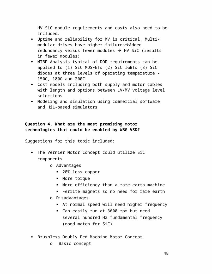
High electrical frequency & High density:
o 1) High speed motors
o 2) High pole count for higher torque etc. (high torque, low speed)
Integration of power system interface (replace transformer)
Enables use of less expensive motor (insulation, rare earth)
Power Slew rate
Better conversion capability can reduce balance of plant by reducing cabling cost
Need Switch mode power conversion system that is cheaper than no VSD
Balance between efficiency and filter size
Now MV drives are custom specialized
Barrior to VSD is
o system integration, since can pass the buck to the motoro Understanding of operation costo First one to implement is disadvantage, so need a
demonstration. Also cost of components is higher before market is established.
o Define todays function specs so retrofit would not change motor requirements.
Advantages:
o Easier to shutdown with VSD than mechanical
Is SiC the way to achieve high voltage?
What additional technology and advanced device performance are needed for HMW VSDs (for example which SiC or Si devices type/voltages etc. would be most beneficial)?
Fail safe, fail conducting
50

Bypass mode
*Short circuit withstand,
RBSOA needed, UIS not required
o Short circuit withstand time limited to microsecond (due to active volume)
Active gate control
Common mode currents
Maximum allowable negative gate voltage
EMC
For HVDC we want 20 kV and greater (therefore IGBT)
Challenges:
o Shoot through is more difficult to prevent due to high switching speeds, more cross talk that may result in more losses – so we slow it down
Mining machine needs better cooling
Auxiliary power supply
Isolated gate drive
Common mode isolation is difficult
Dv/dt
Cooling is difficult
*Need output filter for motor and cable, so do we still need short circuit capability. Needed for bad installation. If we add filter for HF switching then we have inductance and have one less constraint for short circuit capability and change device optimization. *Some attendees feel that Short circuit is still needed.
System integration between motor and drive
Devices are reliable but Modules are not reliable enough yet
51
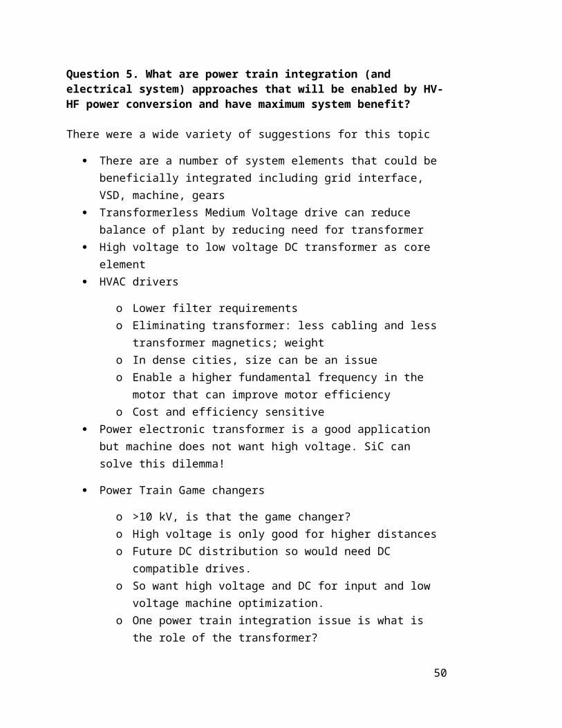
Similarly the phase leg and assembly need to be developed to take advantage of this
Need different devices/types for high power fault current interrupt.
Are there other technologies needed for HMW drive/converters (passive components, gate drives, sensors, controls, and protection devices – contactors, breakers)?
Market and business case analysis study/roadmap
Advanced Package cooling and inductance
DC caps, film capacitors – hard to reduce footprint
Can gain power density from power inverter stack
Output Filter cabinet
o Need dv/dt filter etc. long cables
Cooling unit
What analysis is needed to define the most promising options for HMW VSDs?
What is the benefit tradeoff between using higher voltage of 20 kV SiC IGBT versus 10 kV SiC MOSFETs versus 3.3 kV Si MOSFETs, given different performance of each device type
Tradeoffs for series devices versus larger voltage device (need for balancing)
Key trade-offs: Cost, failure rate, efficiency, power density/weight, power loss
For MV drives, would like 10 kV SiC with a few kHz switching speed, with equal loss to few 100 Hz Silicon
Need to define what the correct voltage is including margins, over voltages etc.
How does short circuit requirement impact on-state voltage, and switching speed
dv/dt issues due to HV-HF being for 3 to 10 times larger than silicon
52

Cost model for overall system with or without SiC for full motor/drive system. Not just lowest cost. Cost versus performance model to pass along to system integrator.
Need to include efficiency of motor/drive and system, not just converter efficiency.
Cost model for the converter, cost model for the motor need to interact.
SOA, pulse current rating, dynamic thermal impedance, loading, thermal limits need to be re analyzed
What are the most promising motor technologies that will complement or be enabled by HMW VSDs?
What is the tradeoff of insulation versus copper in the motor selecting voltage?
Motor insulation voltage
Vernier motor (Lipo)
o Advantage
20% less copper More torque More efficiency than a rare earth machine Ferrite magnets so no need for rare earth
o Downside
At normal speed will need higher frequency. Can easily run at 3600 rpm but need several hundred
Hz fundamental frequency (good match for SiC). Motor generator (ABB)
o Wind Turbine
In many cases drive and motor are from different vendor
Often turbine OEM want multiple suppliers For wind, low speed is gearless, whereas for
compressor, high speed is gearless. The key issue is gear less power train is the goal.
53

o Gearless mill drive: 20s MW
o High voltage motors:
Motorformer for HVDC and oil and Gas
o Motor key points
For oil and gas, reliability is most important Don’t want to be first to try so advanced technology
developer needs partner (possibly a demonstration). Integrated motor and drive close together. Performance versus cost Would like integrated motor/VSD but in many cases
spec drive and motor separately. Motor concept (Longya)
o Basic concept Two MMF on stator plus rotor segments
o magnets on both sides behaves like magnetic gears
o duel mechanical ports Multi-thread winding can aid in resiliency but complex and a lot of
cables.
What are power train integration (and electrical systems) approaches that will be enabled by HV-HF power conversion and have maximum system benefit?
Elements to be integrated
o Grid interfaceo VSDo Machineo Gears
Transformerless Medium voltage drive can reduce balance of plant by reducing need for transformer
o high voltage to low voltage DC transformer as core element
HVAC drivers
54

o Lower filter requirementso Eliminating transformer: less cabling and less transformer
magnetics; weight o In dense cities, size can be an issueo Enable a higher fundamental frequency in the motor that can
improve motor efficiencyo Cost and efficiency sensitive
Power electronic transformer is a good application but machine does not want high voltage. SiC can solve this dilemma!
Power Train Game changers
o >10 kV, is that the game changer?o High voltage is only good for higher distanceso Future DC distribution so would need DC compatible drives.o So want high voltage and DC for input and low voltage
machine optimization.o One power train integration issue is what is the role of the
transformer?o We may not want to forget the gearbox. There may be a role
for better gear boxes. Shipboard compatible drive:
o Space is limited o Permanent magnet motor is more dense.o The present thinking of avoiding high voltage, leads to multiple
poles >3 and more drive cost.o Serviceability, modular design such as multiple poleso MVDC is a future platform to integrate with. Solid state
transformer is a key enabler for this and otherwise. One benefit is modularity.
Toshiba
o Many motor types and applications up to 50 k HPo Energy storage/ PV o UPSo All these products under one roof. o Toshiba motor and drive integrated into one system is not as
integrated as we would like.
55
o MV Drive is ramping up in the last 15 years and now accelerating.
Oil, gas, and mining is biggest marketo Need to accept high input voltage from power delivery, have
higher power, and customized design with module footprint the same.
SST applications for power train integration.
o Good in dc to dc stageo SST can be used for integration into multiple system
voltages
Want to move dc system bus from 1 kV to10kV in many applications (e.g. Navy)
HMW VSD including HF AC-AC stage to integrate machine into different types of medium voltage AC or DC Electric Power System (may have similar voltage but different interconnection needs).
Offshore wind needs higher voltage. Turbine turns slow so need a gearbox. High power, high voltage VSD would help here.
Solid state transformer for traction application; because silicon SST has many levels and 5 kHz switching that has audible noise. Want to get rid of oil.
For DC power systems, we need an analog to 20 kV to 1 kV transformer with galvanic isolation.
What are applications that can use SST? What other functions are needed beyond what a transformer can provide to serve as an early adopter until cost is comparable to transformers.
o If you need MV DC o Solar, need to raise voltage on LV side within HF
conversion stage rather than an LF transformer.o Asynchronous Linko integrated protection
microgrid interconnection
56

E. Compilation of Individual Written Detailed Responses to Key Questions
Key Question 1. What are benefits and barriers of increased penetration of VSD’s for HMW motors?
Written Responses – 11
John Amy - NavyFor the Navy, the barrier first cited is the additional cost of a VSD. The second barrier cited is load current harmonic injection of the VSD back into the supplying power system. The third barrier is that the VSD is not lossless; it adds losses to the system. The fourth is a concern regarding reliability.
Subhashish Bhattacharya – North Carolina State UniversityCapital cost, payback period calculations based on energy savings, issues of dv/dt and filters, size, weight and volume requirements
Roger Cooley – Northrup GrummanBarriers – (Std SiC packages, current rating, market acceptance) cost, Drives – Harmonics, losses reliability
Benefit – Flexibility and higher frequency drives
Rajib Datta – GEEnergy and cost saving in processing or manufacture. In many cases, the application demands it.
Geoffrey Dolan – GoogleBenefits: Greater freedom in motor design to separately optimize motor from the 60 Hz grid. Remove concerns over 50/60Hz compatibility for applications that are shipboard/transportable.
Barriers: Is there a limit to what percentage of spinning reserves can be converted to VSD/constant power loads? Do bi-directionality requirements need to be placed on drives >MW to support grid stability?
Bill Geiwont - VaconReliability - Robicon redefined what reliability means in this industry in the early 90s. I had the opportunity to visit the first field installed CHB from Robicon and spent a lot of time talking to the customer about his experience. He absolutely loved the drive and rambled on for hours about the system. I happened to notice in the corner of the control house a large amount of dead power module cells. I questioned the customer about these dead modules and he confirmed that they were definitely “broken” modules but that because of the N+1 capability of the CHB the customer was never without a drive when he needed it and could schedule a down time to
57

replace the cell that was indicating bad. So therefore it’s not so important that the drive never fail but that it never leaves the customer dead in the water. Depending on the process that is being run by the MV motor it could be between 100k to over 1M dollars an hour if down. In some cases, like extruders, the material may solidify and cause untold damage and take a serious amount of time to get back running. So the point I would like to make is that these HMW drives are typically the main drive for the process and the customer wants AVAILABILITY. Robicon achieved this with adding one more belt of H-bridges (some additional cost). The key is to provide this functionality without additional costs. The HMW drives need to develop simple failure prediction capabilities/algorithms that will inform the customer that either a BUS capacitor or power device is reaching EOL and, like in Robicon’s case, inform the customer that action is required during the next scheduled maintenance time. This would be a shift away from the numerical, probability based techniques toward a more realistic, hardware based technique.
MTBF -Customers are also looking for 20yr life with an 8yr MTBF. Today’s main mill drives (LCI, CC) were developed in the late 70s and most are still running. Obviously the controls have been updated but the power devices, mainly SCRs, are still going strong in most cases. These products have already set the bar for what the customers will tolerate so <20yrs is out of the question.
Short circuit rating of SiC- I understand that in order to achieve what SiC has---it had to give up something…so short circuit was kicked out of the budget. A scenario that has been repeated over the last several decades is one that as new technology is rolled out, and unfortunately failures do happen, that the failure produces a complete plasma melt down of the system. If this occurs it will certainly slow the ramp-up of this technology overnight. When IGCTs were first released they were sold with a gate driver attached. The device suppliers felt the risk was too high to allow users to design their own and deal with field failure issues….and not to mention a bad reputation. I feel that with these high du/dt SiC devices with little or no short circuit survivability it might be worth proposing that initially the manufacturers (like CREE) sell the devices with a gate driver that best optimizes the performance of the device. This will help reduce the overall VSD development time and provide some level of security that a full out plasma meltdown will not occur due to poor gate drive design. Of course as with most things competitors are always looking to differentiate themselves so I suspect that custom gate drives will eventually enter into the picture but hopefully built on the lessons learned by the manufacturer of the device.
Stephen Kuznetsov – Raytheon(1) How big a cost of input harmonic filter to meet stringent harmonic specifications on ship or grid?(2) Cost and size of output harmonic filter can be large and exceed cost of main converter.(3) Predicted lifetime of VSD vs. lifetime of drive motor
Veli-Matti Leppanen – ABB
58

Pluses - energy savings, less wear of process equipment (avoid shocks), better process quality through optimal controlMinuses- cost, need for trained personnel, fear of failure and downtime
Tim McCoy – McCoy ConsultingBenefits – FlexibilityBarriers – Cost, reliability, complexity
John Shegirian – General DynamicsBarriers – Required volume of space. Harmonics reflected back onto system. Depending on voltage, the need for DI water. The need for cooling water in general.
Brij N. Singh - John Deere Inc.Higher DC bus voltage and higher switching frequency of inverter are great advantages for John Deere to use WBG devices. This could result into reductions in DC bus capacitors and cable size between inverter and motor. However, John Deere sees barriers in form of non-availability of cost effective medium and high voltage Permanent Magnet Machines for vehicle traction applications.
Ajith Wijenayake – DRSBarriers – Created system level harmonics is a major issue. Cost is high due to complex system integration. Low loss SiC devices and reliability issues (less field data).Benefits- Size reduction. Lower cable cost. Energy efficiency.
Key Question 1a. What and why are VSDs used for HMW motors today?
Written Responses – 11
John Amy - NavyToday VSDs are used by the Navy because the application requires variable speed. There is some current acquisition motivation to employ VSDs where reductions in energy consumption can be achieved.
Subhashish Bhattacharya – North Carolina State UniversityMV motors used for steel rolling mills, traction, metal industry, lumber industry. These applications require variable speed.
Roger Cooley – Northrup GrummanPower system compatibility - particularly in finite inertia systems i.e. large motor start-up.
Rajib Datta – GEPumps, fans, compressors propulsion, renewables, mining, metal industry, etc.
Krstic Slobodan –Eaton Corporation
59

For Eaton Corporation: Pumps-water processing; Mining applications – conveyors etc.; Oil and gas processing equipment
Stephen Kuznetsov – RaytheonNew requirements from DOD for ultra-quiet/low harmonic distortion VSDs demand multi-phase motors and drives, e.g. 15-24 phase motors. Energy storage systems with flywheel storage require wide-range VSDs and high speed motors
Veli-Matti Leppanen – ABBEnergy savings, less wear of process equipment (avoid shocks), better process quality through optimal control
Tim McCoy – McCoy ConsultingWhere user needs variable speed
John Shegirian – General DynamicsElectric propulsion
Brij N. Singh - John Deere Inc.Need of higher power only possible if voltage ratings are increased else sizing of cable, interconnects, and sensor will be difficult to achieve in a cost effective packaging of electric drive system.
Ajith Wijenayake – DRSElimination of step-down transformer and hence the cost and size.
Key Question 1b. What is the pay-back period that would generate strong market interest?
Written Responses - 11
John Amy - NavyThe Navy answer is 2-4 years.
Subhashish Bhattacharya – North Carolina State UniversityLess than 2-3 years
Roger Cooley – Northrup GrummanEfficiency numbers are believed more than “payback period”
Geoffrey Dolan – GoogleThis seems too application specific. The goal should be reduction in overall system cost at installation. Small premiums may be supported for efficiency but goal for mass adoption should be lower installed system cost.
Krstic Slobodan –Eaton Corporation
60

1-2 years
Stephen Kuznetsov – Raytheon3 year payback essential
Veli-Matti Leppanen – ABBMaybe there could be incentives via some sort of leasing arrangements -the savings could be split between equipment provider and end user.
Tim McCoy – McCoy Consulting3 years or less for commercial applications
John Shegirian – General Dynamics3 years
Brij N. Singh - John Deere Inc.Increased efficiency and increased performance offered with medium and high voltage inverter could result into a realistic payback period of two to three years. If there are additional advantages such as reduced size and improved fuel economy in case of transportation applications for heavy-duty vehicle could be a good customer pull to generate strong market interest.
Ajith Wijenayake – DRSPreferably less than five years (similar to typical payback periods in the commercial drive industry) but may be different for different applications and should consider individual applications.
Key Question 1c. What are efficiency benefits that would warrant incentives?
Written responses - 9
John Amy- NavyA VSD with an efficiency of ≥98% would assuage concerns about increased losses. Just as important is the partial load efficiencies; is there an efficiency drop-off at light load conditions? Does the VSD reduce the overall system energy consumption?
Rajib Datta – GEReally depends on application. Most applications are not efficiency sensitive. Secondary benefit of loss and thermal management may be more critical.
Geoffrey Dolan – GoogleIndustry on island grids could be early adopters –high cost of electricity
Bill Geiwont-VaconAgency & Utility regulations have always lead the need for improved control methods and overall system efficiencies. I look to these policy makers to indirectly
61

push customers into replacing the old soft starters with VSDs to reduce energy consumption and in the case of grid connected generating systems that the AFE will need to play system stabilizer requiring higher bandwidth control systems. While a typical Si based VSD can quickly meet the energy savings goals I believe SiC will be needed, with its higher switching frequency for grid stability control. Krstic Slobodan –Eaton Corporation Efficiency of drive is not critical. Process efficiency benefits from drive and determines the need.
Stephen Kuznetsov – RaytheonEfficiency not important as reliability/MTBF. Efficiencies of 96-97% are realistic goals
Veli-Matti Leppanen – ABBMaybe there could be incentives via some sort of leasing arrangements-the savings could be split between equipment provider and end user.
Tim McCoy – McCoy ConsultingEfficiency benefits relative to what? Si-based VSD’s or direct drive motor applications?
Brij N. Singh - John Deere Inc.As compared to Silicon inverter if WBG (read SiC) inverter offer additional 10% to 15% efficiency, it would be a significant incentive for customers of this new technology
. Ajith Wijenayake – DRSElimination of bulky magnetic MV transformer by a HF transformer is a definite benefit in terms of size and efficiency, but at a higher cost in the short term.
Question 2. Are there VSDs/Converters on the market that incorporate SiC and what is the benefit?
Written responses - 8
John Amy- NavyNot “on the market”. Get SiC modules into application-designers hands so that they can characterize them for themselves.
Subhashish Bhattacharya – North Carolina State UniversityMitsubishi has 1 MW traction drive and also auxiliary power drive for traction.
Rajib Datta – GEBeing introduced in health care equipment (MRI). Primarily hybrid modules are used at this stage. Benefit: high switching frequency with reduced losses.
62

Geoffrey Dolan – GoogleMotor controllers for avionics application. 100 kW 1200V SiC application. We see lower weight and higher efficiency as advantage. Also, lightweight, power dense motors we use have high electrical frequency and low inductance so higher switching frequency from SiC is critical
Slobodan Krstic –Eaton Corporation CorporationYes for PV (not Eaton Corporation). SiC power devices are used in many power supplies.
Veli-Matti Leppaneu – ABBMitsubishi has all-SiC traction drive.
Tim McCoy – McCoy ConsultingNot at the MW class
Brij N. Singh - John Deere Inc.None that I know of
Question 2a. Are demonstration projects needed to confirm performance, reliability?
Written responses - 13
John Amy- NavyYes. Demonstrate MV directly connected front-ends. Demonstrate mitigation of switching effects - common mode/negative sequence currents, EMI, dv/dt
Subhashish Bhattacharya – North Carolina State UniversityYes on MW with SST based DC-DC transformer with galvanic isolation
Roger Cooley – Northrup GrummanYes.
Rajie Datta – GE Absolutely. Without it, it will be difficult to show the disruptive nature of the technology.
Geoffrey Dolan – Google(1) Retrofit existing MV motors with MV drives to demonstrate efficiency gains and control improvements.(2) Design new motor and drive system for application with goal for overall size, weight and system cost improvements
Dave Grider – Cree
63

Select demo projects that identify early adopters and yet would appeal to a broad user base. System demo identifies requirements (performance, reliability, etc.) not only for SiC device/modules but other components (passives, magnetics, gate drives, controls, breakers, etc.)
Krstic Slobodan –Eaton Corporation Yes. Conservative customers need to be convinced. They may not like being an early adopter
Stephen Kuznetsov – RaytheonYes to all. Demo projects must be realistic and combine high density e.g. 4 MW/cu. meter, with 30,000 hour lifetime for drives and converters. DOD needs to have a demo program that uses a 20 kV DC link and 13.8 kV output.
Veli-Matti Leppanen – ABBYes
Tim McCoy – McCoy ConsultingYes. Nobody wants to be the first application/reference.
John Shegirian – General DynamicsYES, required for military applications
Brij N. Singh - John Deere Inc.Yes
Ajith Wijenayake – DRS The major issue is the customer perception of the SiC proven technology and how to overcome them?
Question 2b. Is there a large retrofit market for installation of SiC based VSDs?
Written responses – 11
John Amy - NavyRetrofits only happen if (1) a change in the application demands a change in VSD performance or (2) a cost reduction is achievable; i.e. a positive ROI
Subhashish Bhattacharya – North Carolina State UniversityMaybe, not clear perhaps only on measuring the power output for overload condition
Roger Cooley – Northrup GrummanPossible mostly in higher cost markets - military
Rajib Datta – GENot immediately; it can be a secondary market after new applications are introduced.
64

Geoffrey Dolan – GoogleAre there manufacturing process opportunities available with VSDs and smaller, lower inertia motors?
Slobodan Krstic –Eaton Corporation No. New applications or installations will use SiC drives.
Stephen Kuznetsov – RaytheonVery large market for SiC drives in 6 kV to 15 kV range. I do not see SiC devices competing in the 480-690 VAC market for drives
Veli-Matti Leppanen – ABBProbably not.
Tim McCoy – McCoy ConsultingNo. Si power devices/drives don’t wear out. The controls become obsolete.
Brij N. Singh - John Deere Inc.Yes, I think retrofitting Silicon inverters with SiC devices and establishing advantages WBG technologies in a real application followed by publicity for marketing would be desired to create increased interest in WBG technology.
Ajith Wijenayake – DRSIn general, there is a reasonable size market for MW HP drives. But the drive cost is a major factor and SiC could in the long term address this issue.
2c. Are there specific barriers for HMW applications of SiC for HV-HF switching?
Written responses – 12
John Amy- NavyHV-HF sort of implies a high dv/dt; this would mean insulation design can be challenging
Subhashish Bhattacharya – North Carolina State UniversityYes, insulation issues and parasitic capacitances of the motor
Roger Cooley – Northrup GrummanCM compatibility –effects on system. Passive elements
Rajib Datta – GEProtection and qualification for direct MV connection
.
65

Geoffrey Dolan – GoogleWe would love to see packaging standardization. Multiple vendors are key to marketparticipation. Current IGBT packages are debilitating to SiC.
Krstic Slobodan –Eaton Corporation Yes. Cost, EMI and dV/dt problems, 2nd source for devices
Stephen Kuznetsov – RaytheonReliability and MTBF for SiC compared to conventional 9 kV thyristors and 6 kV IGBTs. Short circuit withstand e.g. 50 kA is important requirement
Veli-Matti Leppanen – ABBReliability concerns.
Tim McCoy – McCoy ConsultingCost. Reliability. System implementation tools/knowledge.
John Shegirian – General DynamicsPerceived reliability
Brij N. Singh - John Deere Inc.Reliability of technology, availability of compatible electric motors and generators, dv/dt and di/dt noise concerns, EMI/EMC issues, lack of packaging knowledge to take effective advantages of high temperature properties of WBG devices
Ajith Wijenayake – DRSOne of the major issues are common mode issues at high switching frequencies limiting the speed of the SiC device capabilities.
Question 3. What advanced VSD performance characteristics are required to achieve system benefits and desired payback estimates?
Written responses - 9
John Amy- NavyThe Navy perspective:
(1) Demonstrate reduced losses (not the same as converter efficiencies)(2) Demonstrate high frequency (higher than Si) wave forms.
Subhashish Bhattacharya – North Carolina State UniversityPerformance in terms of current/torque control
Roger Cooley – Northrup GrummanIncreased Fgas to reduce size and cost of passives
Rajib Datta – GEPower density which should translate to system level cost saving.
66
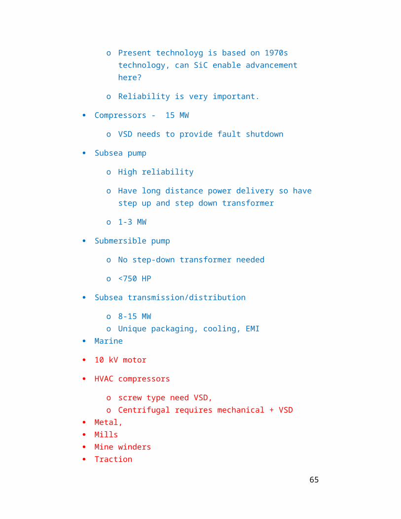
Dave Grider – CreeWhat are requirements of HV SiC Devices and Modules ( 10 kV-15 kV SiC MOSFET, ≥15 kV SiC IGBT) in terms of short circuit capability, SOA (RBSOA, FBSOA), Current, Voltage, Switching Frequency, Thermal Cycling, Operating Temperature
Stephen Kuznetsov – Raytheon(1)Slew rate of VSD in going from full-speed forward to full-speed reverse is an essential and limiting performance characteristic for a bidirectional drive.(2)Ability of a VSD to ride thru a load short-circuit without damage.
Tim McCoy – McCoy ConsultingDepends on specifics of application. Could be – frequency, efficiency, high temperature, size/weight
Brij N. Singh - John Deere Inc.WBG VSD should operate at higher voltage, temperature and switching frequencies as compared to Silicon VSDs.
John Shegirian – General DynamicsReduced cooling and filtering requirements. Elimination of input transformers.
Question 3a. What additional technology and advanced device performance are needed for HMW VSD’s (for example, which SiC or Si devices type/voltages, etc. would be most beneficial)?
Written responses - 12
John Amy- NavyPackaging and the other elements that go into making a module that exploits SiC’s characteristics – voltage, frequency and thermal are needed. Dielectrics, potting compounds are included.
Subhashish Bhattacharya – North Carolina State UniversityBoth LV and HV SiC devices; 3.3 kV and 10 kV MOSFETs
Roger Cooley – Northrup GrummanInsulation systems, HV passive (L.C.) technology. Device packaging.
Rajib Datta – GEHigh reliability devices in 3.3 kV/4.5 kV range. Also high performance cost-competitive modules.
Geoffrey Dolan – Google
67
SiC: 4000 VDC bus compatible, 1000 VDC bus compatible. One comment, differences in device technology may change SOA from 1200V IGBT to SOA SiC MOSFET which makes me want to specify bus rather than devices
Dave Grider –Cree(1) 10 kV SiC MOSFETs - nearest to commercial availability
(2)15 kV SiC MOSFETs – now being demonstrated
For (1) and (2) further 10 kV and 15 kV SiC DMOSFET development should be continued as full JEDEC qualification (3) 15 kV and higher SiC IGBTs – Demonstrated but need to establish reliability For (3) Establish reliability and further development of HV SiC IGBT needed, followed ultimately by JEDEC qualification
Krstic Slobodan –Eaton Corporation SiC at 15kV or 20kV for a 2-3 level 15kV rms class drive
Stephen Kuznetsov – Raytheon(1) Raising current rating on SiC MOSFETs for 4-6 kV devices to be competitive with conventional high speed thyristors 2000-3000 amps average current.(2) Do higher dv/dt s require, additional motor winding insulation?
Veli-Matti Leppanen – ABBV?/kV Vdc/kV Vce@2L [email protected] ~5 ~8.3kV4.16 ~6 ~10.4 kV6.9 ~10 17kV 10 kV11 ~15 X 14 kV13.8 ~20 X 17 kV
The above leading to Voltage classes for SiC devices: Vcc=8 kV, 10 kV, 14 kV, 17 kV
Tim McCoy – McCoy ConsultingNeed to match up to existing infrastructure – i.e. device voltage ratings are driven both by technology and standard voltages.
John Shegirian – General DynamicsHigher currents, 1000 amps or higher at 5 kV or above.
Brij N. Singh - John Deere Inc.For John Deere application SiC devices in ratings of 1700V and 2400V and 600A to 900A devices could be a good start, idea is to avoid parallel operation of inverters made of 1200V rated silicon devices for higher power needs. One of John Deere customers operates 4 inverters in parallel with each inverter rated at 500kW and there
68

are total sixteen inverters on the vehicle for all four wheel drive with electric motor directly mounted on vehicle wheel.
Ajith Wijenayake – DRSCommon mode isolation issues at higher saturation frequencies. dv/dt at the motor terminal is critical to motor protection. Gate drive designs are different than Si IGBT drives and need to be optimized.
Question 3b. Are there other technologies needed for HMW drive/converters (passives, components, gate drives, sensors, controls, and protection devices-contactors, breakers)?
Written responses – 12
John Amy- NavyDon’t get hung up on this
Subhashish Bhattacharya – North Carolina State UniversityYes
Roger Cooley – Northrup GrummanIf drive is small and switchgear huge, benefit is smaller.
Rajib Datta – GEAll of the above but key is integration within a high-performance building block
Geoffrey Dolan – GoogleYes. Gate drivers with overcurrent protection (similar to Vsctz protection in IGBT drives) would be helpful. Magnetic materials optimized for filtering drive output ->high saturation flux density.
Krstic Slobodan –Eaton Corporation Yes Filters, gate drives, control power w/dv/dtProtection is not critical-fuses/breakers OK for AC systems. DC needs breakers.
Stephen Kuznetsov – Raytheon (1) Gate drives are essential for further development. I know of none sold commercially at 150C(2) Passive components such as 200C capacitors are not well developed and their reliability at high temperature is poor.
Veli-Matti Leppanen – ABBPower electric transformer for front end connection. Cost parity based on saving between (MV) Supply cable Cu and inverter and motor (LV)
69

Tim McCoy – McCoy ConsultingYes. All those mentioned and system issues - common mode currents; cooling;
Brij N. Singh - John Deere Inc.(a) High performance low cost current sensor that could withstand ambient temperature up to 150 deg C are needed for inverters that are fully sealed in applications where water intrusion is avoided by environmental sealing
(a) High temperature and high voltage film capacitor is must for inverter. Polypropylene film capacitors don’t offer desired reliability and durability. Cost effective 125 deg C technology is needed and that would be a good start
(b) For cost reductions and yet optimized fast control systems, most of motor control system should be implemented in FPGA to achieve SiL and safety.
(c) WBG inverter may need L-C filter to prevent electric machine failures caused by dv/dt and over voltage transients
John Shegirian – General DynamicsTechnology improvements for the other drive components such as capacitors and magnetics are needed to improve overall drive power density.
Ajith Wijenayake – DRSGate drives have to address device interaction for higher reliability at higher switching frequencies. Short circuit protection is an issue due to smaller size of the chip in comparison to Si chips.
Question 3c. What analysis is needed to define the most promoting options for HMW VSDs?
Written responses - 10
John Amy- NavyThermal capacity of SiC switches in a module.
Rajib Datta – GEWhat device voltage makes sense?
Geoffrey Dolan – GoogleCreepage, clearance and insulation systems that meet the parasitic inductance and capacitance requirements for SiC performance to feed into packaging design.
Dave Grider –Cree
70

HV SiC (WBG) devices will be developed in response to market needs. Price of SiC devices will decrease substantially with volume (as it has for 600-1200V SiC devices). Therefore in order to decrease cost of HV SiC devices (this should be included in any cost model), we need to identify early adopters to provide production volume that will lead to reduced costs. HV SiC module requirements and costs also need to be included.
Krstic Slobodan –Eaton CorporationUptime and reliability for MV is critical. Multi-modular drives have higher failuresAdded redundancy versus fewer modules HV SiC (results in fewer modules)
Stephen Kuznetsov – RaytheonMTBF Analysis typical of DOD requirements can be applied to (1) SiC MOSFETs (2) SiC IGBTs (3) SiC diodes at three levels of operating temperature -150C, 180C and 200C
Veli-Matti Leppanen – ABBCost models including both supply and motor cables with length and options between LV/MV voltage level selections
Tim McCoy-McCoy ConsultingMarket Analysis –What is the killer app?
Brij N. Singh - John Deere Inc. Modeling and simulation using commercial software and HiL based simulators
Ajith Wijenayake – DRSReliability/system interaction (between the drive and the motor). Actual system level efficiency in comparison to Si based inverter.
Question 4. What are advanced machine technologies that could be enabled by WBG VSD?
Written responses – 3
Bill Geiwont-VaconI personally believe the first application for SiC should be one where SiC is clearly advantaged over Si. We understand because of the WBG structure that SiC is 100x better than Si in cosmic-ray situations. Chile has the best location in the world for PV and mining at elevations >20k feet. At this level the Si power devices must be de-rated because of cosmic-ray and air density. I would see this as a break-thru area that SiC can be showcased.
Krstic Slobodan - Eaton Corporation
71

High speed motors having a high fundamental frequency. These require higher frequency PWM for low drive output harmonics, and to drive these typically low inductance motors (e.g. usually PM).
Brij N. Singh - John Deere Inc.High power high voltage PM machines are desired for traction application due to wide range of constant torque-speed characteristics offered by PM machine when compared with SR and induction motors.
Question 5. What are power train integration and machine tech integration opportunities?
Written responses – 2
Slobdan Krystic - Eaton CorporationPerhaps integrated drive+motor+pump for some oil and gas applications.
Brij N. Singh - John Deere Inc.VSD integration on heavy-duty on-highway and off-highway vehicle platforms is John Deere interest and there exist internal proprietary knowledge within company.
Question 6. What are applications that can use SST. What other functions are needed beyond what a transformer can provide to serve as an early adopter until cost is comparable to transformers?
Krstic Slobodan - Eaton Corporation(1) MV DC distribution can benefit from the isolated DC/DC converter portion of an SST. (2) An SST that limits fault current could benefit some applications. These might also use fast response solid state circuit breakers as part of the system.
Brij N. Singh - John Deere Inc.For packaging and cost reasons, John Deere likes to use reduced size magnetics, most likely John Deere may not use SST except magnetics needed for 50 kW-rated DC-DC converter to get 56 V safe-touch power from high voltage WBG inverter DC bus.
72
73