Proceedings of the 1st symposium Knowledge Exchange for Young Scientists … · Properties of fresh...
197
Proceedings of the 1 st symposium Knowledge Exchange for Young Scientists (KEYS)
Transcript of Proceedings of the 1st symposium Knowledge Exchange for Young Scientists … · Properties of fresh...

Proceedings of the 1st symposium
Knowledge Exchange for Young Scientists (KEYS)


Proceedings of the 1st symposium
Knowledge Exchange for Young Scientists (KEYS)
Sub-Saharan African Standards for
Cement and Concrete Research
-
Raw Materials, Quality Control and Maintenance of
Cementitious Products
9th – 11th June 2015, Dar es Salaam Tanzania

Editorial information
1st international symposium
Knowledge Exchange for Young Scientists (KEYS)
Proceedings
2015
Edited by
Nsesheye Susan Msinjili and Wolfram Schmidt
BAM Federal Institute for Materials Research and Testing, Berlin, Germany
Published by
BAM Federal Institute for Materials Research and Testing
Unter den Eichen 87
12205 Berlin, Germany
Tel: +49 30 8104-0
Fax: +49 30 811-2029
Email: [email protected]
Website: www.bam.de
Copyright © 2015 by
BAM Federal Institute for Materials Research and Testing
ISBN 978-3-9817149-3-7

1
Foreword Welcome to the first symposium on Knowledge Exchange for Young Scientists (KEYS) in
Dar es Salaam, Tanzania, 9th – 11th June 2015. This symposium is part of a three phase
series organised by BAM, and funded by VolkswagenStiftung. Each symposium will focus
on relevant themes in the construction sector and will include adequate training as well
as offer an opportunity to participate in informal discussions between key players and
young scientists, which will facilitate the fundamentals of knowledge transfer.
Our world of cement and concrete faces tremendous challenges for the future. Without
doubt cement-based materials will remain the most widely used construction materials in
the world. Concrete can be made available everywhere in the world, and it is more
sustainable than other materials. Nevertheless, in order to become even more
sustainable, we need to find solutions to reduce CO2 generation for the cement
production, to quickly solve problems of housing and infrastructures, and to cope with
ever increasing customer needs in terms of performances.
There is no global optimum solution for concrete. Best concrete practices always has to
be found locally and regionally based on raw materials, supply chains, and construction
needs, but it can be inspired by other regions. In order to tackle the future challenges
and build more innovative with concrete, we need to enhance interdisciplinary
engineering skills and create networks between future decision makers.
Therefore, the KEYS symposia series offers a platform whereby young African scientists
can get together with peers from Germany as well as with experienced academic
engineers, industry specialists and scientists from across the globe for better
implementation of research analysis in their respective fields of study. This primarily
provides the opportunity to obtain further knowledge in the demand for the home-base
innovation and growth of the education sector. It will also provide an opportunity to
network with their peers and gain relevant and objective knowledge.
The theme for this first symposium is sub-Saharan African standards for cement and
concrete research – raw materials, quality control and maintenance of cementitious
products. The symposium is divided into 8 sections and includes presentations from
9 international keynote speakers and 22 young scientists, who were selected out of a
high number of applicants based on the excellence of their scientific writing.
We would like to thank all participants for their valuable contribution to the symposium.
We are blessed to receive tremendous input from the distinguished keynote speakers and
we thank them for their attendance. Last but not least, we would like to acknowledge the
funding body, VolkwagenStiftung, for their support. We hope you enjoy the symposium
and find your engagement valuable with the entire team in sustaining your professional
development in the global world of cement and concrete.
Nsesheye Susan Msinjili
BAM Federal Institute for Materials Research
and Testing, Berlin, Germany
Wolfram Schmidt
BAM Federal Institute for Materials Research
and Testing, Berlin, Germany

2

3
Table of contents
Practical options for more sustainable cement based building
materials
Karen L. Scrivener 9
Embedded sustainability driven approach into construction
Mohammed Sonebi 25
Parameters controlling superplasticizers cement interactions during
the casting and hardening of cement based systems
Wolfram Schmidt 31
Quality control of reinforced concrete structures for durability
Mark Alexander 37
Cementing our future through innovation: novel approaches to
enhancing the quality of concrete
Raissa Ferron 43
From lab-crete to real-crete, the people + planet = profitable
projects approach
Boudewijn Piscaer 47
Sustainable binders and new ways of construction
Angel Palomo 51
Sustainable concrete made from recycled aggregates
John Makunza 57
Dry-stack and compressed stabilised earth-block construction:
Exploring new frontiers in construction
Herbert Uzoegbo 63
Cassava peel ash: An engineering pozzolanic material
Kolawole Adisa Olonade 77
Compressive strength characteristics of bamboo leaf ash blended
cement concrete
John Temitope Kolawole 83
Physical and mechanical properties of a Portland cement blended
with silica undersaturated carbonatitic lavas as natural pozzolans
Apollo Buregyeya 87

4
Performance of ternary cementitious binder systems incorporating
untreated and treated pozzolanic materials
Bartosz Bobkowski 93
Influence of gum Arabic Karoo in concrete and cement mortar as
retarding and water reducing admixture
Rose Mbugua 97
Effect of fly ash-β-cyclodextrin composites on concrete properties
Bolanle Deborah Ikotun 103
Determination of suitable additive to improve local Portland cement
for offshore construction
Alice Titus 109
Properties of fresh self-compacting concrete containing slag
Omar Kouider Djelloul 115
Shotcrete
Maria Thumann 119
Rice husk ash as a source of soluble silicate in the design of
metakaolin based inorganic polymer cement and mortars
Elie Kamseu 125
The structural behaviour of pozzolan-lime cement as a potential
substitute to Portland cement in low-strength construction
applications
Dans Nshekanabo Naturinda 131
Properties of FaL-G bricks
Stephano Inyasio 137
Earthen building materials: Hydraulic lime based grout for
retrofitting and CEBs stabilised with geopolymer binders
Lorenzo Miccoli 141
Making durable concrete through inhibition of chloride ion
Penetration by pozzolanic action
Mayowa Catherine Ikumapayi 145
Development of prediction models for the carbonation of reinforced
concrete
Yunusa Alhassan 151

5
Durability characteristics of concrete containing sugarcane waste
fibre ash (SWFA)
John Mwero 157
The influence of concrete mix design on the shear strength of
reinforced concrete flat slabs
Farai Ada Shaba 163
Durability of locally produced burnt clay bricks
Kwadwo Mensah-Darkwa 167
Influence of metakaolin on the performance of concretes
Mohammed Si Ahmed 173
The effectiveness of recycled waste nylon in the partial replacement
of fine aggregate in reinforced concrete slab
Rauf Olayiwola Hassan 177
Use of sugarcane bagasse fibre as a soil reinforcement material
Vincent Oderah 183
Earthen Panels – Quality control for an industrially prefabricated
building component made of natural raw materials
Astrid Paul 189

6

7
KEYNOTES

8

9
PRACTICAL OPTIONS FOR MORE SUSTAINABLE CEMENT BASED
BUILDING MATERIALS
Karen L. Scrivener
Laboratory of Construction Materials, EPFL Lausanne, Switzerland
Brief author biography
Karen Scrivener PhD graduated in Materials Science from University of Cambridge, UK
and has a doctorate from Imperial College, London, UK. She is Professor and Head of the
Laboratory of Construction Materials, at EPFL, Ecole Polytechnique Fédérale de Lausanne,
Switzerland. The work of this laboratory is focussed on improving the sustainability of
cementitious building materials. She is the founder and co-ordinator of Nanocem, a
Network of industry and academia for fundamental research on cementitious materials
and Editor-in-Chief of Cement and Concrete Research, Switzerland.
Introduction
Options for more sustainable cementitious materials are reviewed. The most viable
option involves blending Portland cement clinker with increasing levels of supplementary
cementitious materials (SCMs), but the availability of common SCMs is low compared to
the demand for cement. Calcined clays are the only other materials that are potentially
available in large enough amounts to continue the trend of reducing clinker content in
blended cements. Recently we demonstrated that partially replacing clinker by calcined
clays combined with limestone (LC3 blends) can be used to achieve blended cements with
good performance at much lower levels of clinker. Such blends can make a significant
contribution to the reduction of CO2 emission associated with cement production.
As global demand for concrete follows the growth of the middle class in the 21st century,
the concrete industry faces one defining challenge: finding ways to increase the
availability of concrete while at the same time reducing its environmental footprint. To
have a significant global impact, solutions have to be abundant, affordable, and adapted
to the users in the developing world, where most growth is expected.
Concrete is an eco-efficient material
Cement and concrete are essential to the infrastructure of the modern. No other material
is able to fulfil the growing demand for building materials with such a low environmental
footprint. Its widespread availability and low cost make cement by far and away the most
used material on earth, with reinforced concrete accounting for more than half of all the
manufactured materials and products we produce. It is only because of these enormous
volumes that overall the production of cement and concrete is estimated to account for
around 5-8% of man-made CO2 emissions.
Table 1 shows relative figures for the energy and CO2 emissions of some common
building materials [1]. Here, typical values for concrete are shown, as this is the final
product used in the field. As discussed elsewhere [2], there is a huge scope also for

10
reducing the amount of cement in concrete and it should always be borne in mind that
sustainability can and should be considered at all stages of the process. The figures in
Table 1 are per kg and the strength of concrete is not the same as the specific strength
of steel or wood. These issues have been considered by several authors [e.g. 3].
Nevertheless, the advantages of concrete remain clear in most construction related
application; even more so when the availability of materials to substitute concrete is
considered. As an example, although the amount of wood used worldwide is around one
tenth that of concrete, our consumption of wood is already considered to be
unsustainable; we are cutting down more trees than we are planting. It follows that,
independent of any other considerations; wood cannot make a significant further
contribution to meeting the increasing demand for building materials worldwide.
Demand for cement is increasing
Figure 1 shows the projected increase in demand for cement. Most of the increase in the
coming decades will be in emerging and developing countries, which already make up
over 80% of global production. Today, China’s production alone exceeds that of the
whole world 10 years ago. India is the country in which the increase is likely to be the
largest – today the consumption per capita in India is only 1/6th that in China.
Options to reduce environmental impact
Cement production accounts for the overwhelming majority of the CO2 emissions
associated with concrete. Unlike other materials, less than half (~40%) the CO2 emitted
during cement production is related to fuel and electricity. The remaining 60% comes
from the decomposition of the main raw material – limestone, or CaCO3. Great
improvements have been made in the last few decades in lowering energy-related CO2.
Today, the production of Portland cement clinker is one of the most efficient industrial
thermal processes in existence (approaching 70 % of theoretical efficiency) and it is
unlikely that significant further gains can be made here as discussed in more detail by
Gartner [4]. Furthermore cement plants can now use a wide range of substitute fuels,
reducing the need for primary fossil fuels to below 20% in some modern plants. This
versatility, the fact that the calorific value of such a wide range of waste products can be
exploited in a safe manner, should be seen as another advantage of cement production.
Any attempt to reduce the remaining 60% of “chemical” emissions coming from the
decarbonation of limestone will have the inevitable consequence of changing the
cement’s chemistry. Consequently, the reactions and performance of new materials will
not necessarily be the same as the reference Portland cement. It took more than 100
years of empirical testing to develop the basis for use of Portland cement. The use of the
most common blended materials – blends of Portland cement clinker with slag and fly
ash – has taken more than 30 years to become established. We do not have the time to
go through this long testing phase for every new material that comes along. That is why
we must now move towards a more scientific basis, which can only come (on a
reasonable timescale) through a systematic understanding of cementitious processes and
materials at the nano-scale, extended across all the scales involved in cement and
concrete production, to provide the multidisciplinary assessment and prediction tools
needed to assess the functional and environmental performance of new materials.
The options for new cement chemistries are ultimately limited by the composition of the
earth. Just eight elements constitute more than 98% of the earth’s crust – oxygen,

11
silicon, aluminium, iron, calcium, sodium, potassium, and magnesium. The relative
abundances are shown logarithmically in Figure 2 [5]. As a first approximation, cost will
be closely related to availability, leaving only 7 oxides as possible candidates for cement
making. These are summarized in Table 2, which broadly considers first potential to from
space filling hydrates and then their geological distribution.
The potential to form space-filling hydrates is the key to hydraulic cement. First, the
anhydrous cement is mixed with water. The solid content of the resulting mixture cannot
exceed around 50% (W/C ~ 0.3) if the mixture is to be flowable. Then the anhydrous
material must dissolve and precipitate new solids incorporating water with a higher solid
volume than the original anhydrous material. The phases present in Portland cement
clinker are ideal in this respect as there is roughly a doubling in solid volume, which
enables most of space initially occupied by water to be filled, yielding a strong solid with
low porosity.
The alkali oxides retained from Figure 2, Na2O and K2O, cannot produce hydraulic
compounds as these have a very high solubility and will not deposit hydrates.
Nevertheless, small amounts of these compounds play an important role in Portland
cement, where they nearly all end up in the pore solution, conferring the concrete with
the high pH needed to protect reinforcement. Iron and magnesium oxide, on the other
hand, lead to the opposite problem. These oxides do form insoluble hydrates, but
because their mobility in the alkaline pore solution of cements is very low, these hydrates
are almost exclusively deposited within the boundaries of the original grains and do not
contribute to filling the space initially occupied by water or to binding the grains together.
Even in very old cement pastes (even > 100 years [6]), we see bright areas
corresponding to the original ferrite phase in the cement, as in Figure 3 (a). In slag
cements, the magnesium component of the slag remains within the boundaries of the
original slag grains and does not contribute to binding the materials together (Figure 3
(b)).
This brings us back to the three oxides that dominate Portland cement – lime, silica and
alumina.
Strategies to lower the environmental impact of cement manufacturing are already
applied by the industry and their future potential has been evaluated in detail in by the
IEA (International Energy Agency) for the Cement Sustainability Initiative (CSI) study of
the World Business Council for Sustainable Development (WBCSD), from which Figure 4
is adapted [7]. Today the three most important approaches are:
1. Improvement of energy efficiency (red part);
2. Use of biofuels and other alternative fuels (blue part), and
3. Replacement of clinker by substitute materials or supplementary cementitious
materials (SCMs). Materials used include fly ash, various slags, and natural
pozzolans (green part).
Beyond these approaches the CSI study imagines the remaining reduction in CO2 to
come from Carbon Capture and Storage (CCS) (grey area), which is now widely thought
to be, at best, very expensive (increasing cement prices 2-4 times). As seen in the Figure
4, the further gains from energy efficiency are limited as they are reaching a plateau of
optimization. Gains from alternative fuels are projected to increase, but remain a fairly
modest proportion of the total. The projected impact of the third option, substituting

12
clinker by SCMs, is limited by the forecast supply of commonly used SCMs, notably slag
and fly ash. For example, although slag can substitute up to 90% and typically 70% of
clinker in blends, the worldwide amount of slag available is only around 5% of the
amount of clinker produced. Fly ash, although available in larger amounts (around 30%
of clinker worldwide, but absent in many countries), is of variable quality and much is
unsuitable for cement production. So the strategy of clinker substitution could go much
further if new sources of SCMs were available. However very few materials are available
in the large quantities needed for cement production.
Radically different technologies
Before discussing in detail alternative supplementary cementitious materials it is
important to say something about radically different technologies such as alternative
clinkers or clinker free materials.
Alternative clinkers
Figure 5 shows the “chemical” CO2 emissions of the hydraulic minerals in the CaO – SiO2
– Al2O3 – (SO3) system from two perspectives: first per g of anhydrous material, then per
ml of hydrates that can be formed, this latter is related to their space filling capacity and
so to strength development. The volume of hydrates for the aluminate compounds
(monocalcium aluminate and ye’elimite) is shown with and without added sulphate. Here
it can be seen that the figures for the two most important Portland cement clinker
minerals – C3S and C2S – have fairly similar values. Notably we see that C2S only
presents a saving of around 10% in CO2 compared to C3S. This means that for belite rich
cements to represent a “real” CO2 saving, they have to have more than 90% of the
performance of alite rich cements. Despite intensive research efforts, we are far from
achieving this in terms of the performance needed in modern construction. This table
clearly shows that the most interesting minerals from the point of view of their
associated CO2 values are monocalcium aluminate (CA), the main component of calcium
aluminate cements (CACs), and ye’elemite or Klein’s compound (C4A3$), the main
component of calcium sulfoaluminate cements (CSAs or SACs). It is therefore worth
discussing the viability of clinkers based on these mineral in some more detail.
The main problem is that while alumina is very abundant in the earth’s crust, it exists
mainly in feldspars and clays, where it is present alongside silica with Si:Al ~ 2 similar to
that found in most Portland clinkers. To obtain the desired alumina a rich compound, a
more concentrated source of alumina is needed, typically bauxite. But bauxite is not
nearly as widely distributed as clay minerals and is highly sought after for the production
of aluminium, making it is a much more costly raw material. But this is not the end of the
story, as will be explained from the perspective of calcium aluminate cements.
Calcium aluminate cements (CACs) have been in commercial production for nearly 100
years, yet the total amount produced annually is less than 1/1000 of the production of
Portland cement clinker, and only a small proportion of this is used in construction. This
is because the cost of CAC is more than five times the cost of Portland cement. The high
cost of raw materials and production accounts for only part of this huge discrepancy. The
other part lies in the number of people needed to support the use of this special material,
in terms of factories producing smaller amounts, and sales and technical assistance for a
specialised material that does not behave in the same way as the reference Portland

13
cement. Consequently the use of CAC can only be justified where their special properties
justify the higher cost.
Calcium sulfo aluminate cements have gained a lot of attention recently, as, in addition
to the low chemical CO2 of ye`elemite, the firing temperature is lower and they are more
easily ground. CSAs are a very diverse family of cements. They may contain from 70%
ye’elemite down to 30% or less. The main other phase that is present is usually belite.
This leads to a two-stage development of properties, with the fast reaction of the
ye’elemite giving early strength and the belite hydration giving later strength gain.
Another complication is that the behaviour can be changed from rapid hardening to
expansive by the amount of calcium sulphate added during grinding. Due to this diversity
it is difficult to generalize, but it can certainly be said that today, these are specialist
products along the lines of CACs rather than cements for general construction. They have
been produced in China for several decades and have been used for some large-scale
constructions, yet to this day, they represent less than 0.1% of the cement produced in
China and are mostly used for internal partition walls.
Personally, I am doubtful that CSA cements can be competitive with blended cements
discussed below on either an economic or environmental basis in general use. The need
to support consumers in their use of cements that behave differently to the Portland
reference, in addition to the higher raw materials cost, will mean that the commercially
viable cost will be very much more than that of Portland cement. Nevertheless such
developments may be interesting in more specialist applications, for example for precast
concrete.
Clinker free binders
At present many researchers (and funding agencies) are attracted by the idea of “clinker
free binders, such as alkali activated materials, also known as “geopolymers,” claiming
their advantages as low CO2 cements. Despite the hype, it is highly unlikely that such
materials will have a major impact on the sustainability of cementitious materials for
many reasons:
First, the environmental advantages of these materials are questionable. The
environmental assessment made by Habert et al [8] indicates that while the
production of geopolymer concrete can have a slightly lower impact on global
warming than standard Ordinary Portland Cement (OPC) concrete, it has a higher
environmental impact regarding other impact categories related to the production of
concentrated sodium silicate solution and the dangers of handling highly alkaline
solutions.
Second, the performance of these materials is very sensitive to small variations in
the starting materials, such as slag or fly ash. The setting time and rheology are
difficult to control and may vary widely on a batch-to-batch basis. They are also
very sensitive to contamination by conventional Portland cements. This makes use
on-site by typical construction workers challenging.
Third, the durability and long term performance of these materials is not well
known.
Finally, and perhaps most importantly, the materials used in these alkali activated
materials are the same SCMs discussed above – slag, fly ash, etc., which are only

14
available in relatively low amounts compared to cement clinker. The materials that
perform best in these systems are the same as those that perform best in cement
blends.
So from a practical point of view, one is faced with a choice of how to use slag: either (a)
as a component of a Portland based blend in a well-known and tested technology with
proven durability that can be used in existing mix designs with conventional equipment,
or (b) in a clinker free system with the attendant problems of sensitivity, strongly alkali
materials, risks of contamination, and unknown long-term performance. Again the cost of
providing technical support to users also means that a price significantly higher than that
of Portland cement will have to be charged for such materials to be a commercially
viable.
Alternative SCMs: LC3 – limestone, calcined clay, clinker cements
Faced with the limited supply of traditional SCMs, the key question becomes: what
alternative SCMs are available in the very large quantities needed? Materials such as
plant ashes, notably rice husk ash, can be interesting, but the quantities available are
relatively small and localized (both geographically and to certain periods of the year).
There are extensive reserves of natural pozzolans worldwide (e.g. volcanic ashes), but
generally these have a fairly low reactivity and are very variable from place to place. The
one material which has a real potential to make a significant contribution to lowering the
clinker (and so CO2 emissions) of cement is clay, which becomes reactive when calcined
at temperatures between 600 – 800 °C.
The use of calcined clays as pozzolans has been known for some time, it was widely used
in India in the 1970s (before fly ash was widely available) and is currently being used in
countries without supplies of the common SCMs, notably Brazil. However, substitution
just as a pozzolan is only practical up to about 30%, at which level the cost of calcination
usually does not make this an economically viable option. Recently, it has been shown
that by making a coupled substitution of calcined clay with limestone, an additional 15%
or so of clinker can be replaced by limestone with no decrease in mechanical
performance so that the extra saving of clinker can offset the cost of calcination. This is
because the aluminate component of the calcined clay can react with calcium carbonate
(limestone) and calcium hydroxide to produce space filling corbo aluminate hydrates:
A(from calcined clay) + Cc + 3CH C3A.Cc.H11
Clays are the weathering product of all rock types and as such are abundantly available
close to the earth’s surface in all geological settings. They are made up of silicon and
aluminium oxides, which together constitute around three quarters of the earth’s crust.
The most suitable clay types, those containing kaolinite, are typical in tropical and
subtropical environments, where most of the increase in demand for cement is forecast
to occur. Kaolinite clay occurs in abundance in association with soils that have formed
from the chemical weathering of rocks in hot, moist climates, Alfisols (pale green) and
Ultisols (yellow) on the map (Figure 6.). This confirms the abundance of clay, especially
in India and South East Asia.
The potential for ternary blends of limestone, calcined clay and clinker, which we call LC3
(limestone calcined clay cement), to give good performance at 50% clinker content or
less has been demonstrated in the collaborative research between the Laboratory of
Construction Materials (LMC) at EPFL, Switzerland, and CIDEM in Cuba [10].

15
The kaolinite content needed for LC3 blends is much lower than for the “pure” kaolinitic
clays used in the ceramic or paper industries. This means that the use of such “low
grade” clays would not compete with demand for resources by other industries. Our
experience in India [11] has shown that abundant amounts of low-grade clays exist as
over or under burden in existing quarries, currently regarded as waste. The use of such
resources would not require opening new quarries nor deplete agricultural soils. With an
optimum at around 700 to 800°C, the calcination temperature is much lower than the
1450°C needed for clinker manufacturing, hence consuming less fuel. Furthermore, this
calcination process does not emit chemical CO2 and can be carried out with existing
equipment (rotary kilns or tower calcinations units).
Limestone is always available at cement plants. The LC3 blends typically contain around
15% limestone, and limestone unsuitable for clinker production can be used. For
example, high dolomite contents produce periclase during clinker production, which
causes expansion. Such materials can be used safely in interground materials, leading to
more efficient use of limestone quarries. Depending on the exact scenario, the amount of
cement that can be produced from the same identified limestone reserve could be
increase by up to a factor of two.
Further important advantages of LC3 technology are:
Cheaper or similar production costs
LC3 can be produced using the existing equipment in a cement plant
Use of LC3 also does not need any major changes in concrete technology.
This leads to an enormous potential for rapid uptake of the technology with significant
potential for CO2 reduction and efficient use of resources.
LC3 has the potential to provide a large-scale solution to the two main challenges facing
the production of building materials today. A rough estimation of the impact of LC3 on the
CO2 reduction scenarios is evaluated in relation to the results of the WBCSD CSI study
[7] (Figure 7). This assumes that the supply of SCMs can be increased by a fairly modest
600 million tonnes worldwide by 2050. This graph shows how LC3 can significantly
contribute to the growth of the cement sector without increasing emissions.
This is more feasible than compensating a business as usual strategy with carbon storage
and capture. Importantly, the uptake of LC3 would allow developing countries to satisfy
rapidly growing demand while reducing the CO2 intensity of their activities and is thus a
politically very attractive global environment option.
Strength of LC3 blends prepared from low grade clays
Further investigating the potential of blends based on limestone, calcined clay, and
clinker (LC3), blends incorporating calcined clay from several countries (India, Brazil,
Thailand, Cuba) were analyzed. An example of the strengths obtained is shown in Figure
8.
Plotting these results against the kaolinite content of the clays, it can be seen that
kaolinite content is the main parameter determining strength development (Figure 9).
In these experiments the cements were prepared by intermixing based on the same
ground clinker. It can be seen that the one day strengths are still rather low, but, for a

16
kaolinite content of 50% or more, higher strengths than the reference are achieved by 7
days. In practice one day strength can be improved by intergrinding as is currently done
for many fly ash blended cements.
Durability of LC3 cements
When considering a new cement formulation, the question of durability is of prime
importance. Will these materials perform as well as existing materials over the lifetime of
a typical building or structure? A wide-ranging and detailed study of the durability of LC3
is underway in Switzerland, India and Cuba. This study will look at the Underlying
scientific mechanisms as well as full scale exposure. However, we have every reason to
expect that these materials will have good durability:
First, the phase compositions of the materials is very similar to existing Portland
and blended cements. The principal hydrate is calcium silicate hydrate, C-S-H,
whose long-term behaviour is well known and understood. The other aluminate
containing phases, mono and hemi carbonate and ettringite are also formed in
limestone cements, widely used in Europe for many years.
Second, analysis of the pore structure shows that, as for other blended cements
[e.g. 12], the pores are smaller, even though the overall porosity may be slightly
higher (Figure 10) [13].
Third, preliminary results on the resistance to penetration of chloride ions are
extremely good. Figure 11 shows the chloride profiles after two years ponding in
0.5M NaCl solution [13].
Concluding remarks
Fulfilling the needs of the growing world population for food and habitation and at the
same time avoiding drastic climate change due to the emission of greenhouse gasses is
the most important challenge facing the world today. In the field of building materials,
cement and concrete remain the best option as they can be produced in large quantities
almost anywhere in the world and have an intrinsically low environmental footprint
compared to alternatives. Nevertheless, they are the focus of intensive research efforts
to reduce the 5-8% of CO2 emissions attributable to their production. This paper tries to
present a brief but comprehensive analysis of options for cements of the future, starting
from the composition of the earth and considering the practicalities of producing such a
low cost material that can be used by anyone, even with little or no training. This shows
that blends in which around half of the conventional Portland cement clinker is replaced
by a combination of limestone and calcined clay – LC3 blends – present an extremely
promising option to achieve lower CO2 emissions, lower costs, and increase supply –
particularly in tropical and subtropical countries where the increase in demand will be the
highest in coming decades. We have already received strong expressions of interest in
this technology from many cement producers worldwide.
More work is needed to provide a solid scientific and engineering foundation for these
new materials. A large body of work is already underway, undertaken by a network of
researchers in Switzerland, India, and Cuba. The core of this work has been made
possible through significant funding provided by the Swiss Agency for Development and
Collaboration. In the coming years, we hope to extend this network to more countries as

17
a co-ordinated worldwide effort is needed to accelerate the introduction of such
environmentally friendly options.
Figures and tables
Table 1: Embodied energy and associated CO2 emissions for common construction
material [1]
Table 2: Summary of suitability of common oxides for cementitious materials

18
Figure 1: Forecast rise in cement production until 2050 (adapted from CEMBUREAU)
Figure 2: Relative abundance of elements, source US Geological Survey via Wikipedia [5]

19
Figure 3: (a) Micrograph of old concrete shows low mobility of iron, which remains in the
bright areas corresponding to the ferrite phase in the original cement grains.
(b) Micrograph of slag cement paste shows low mobility of magnesium, which
remains within the boundaries of the original slag grains.
Figure 4: CO2 reduction scenarios compared to 2005 baseline from CSI study Low (a) and
high (b) scenarios for demand increase

20
Figure 5: CO2 emissions related to the major hydraulic minerals
Figure 6: World soil map. Kaolinite rich clays are most likely to exist near the surface
(tap 5m) in the yellow and pale green regions [9]
Figure 7: Potential additional reduction of CO2 by clinker substitution through the use LCC
( calcined clay, limestone) technology.

21
Figure 8: Strength development for a range of blends all containing 50 % clinker, 5 %
gypsum, 15% limestone and 30 % calcined clay. The calcined clays originate from India,
Brazil, Thailand and Cuba
Figure 9: Relation between kaolinite content of the clay which is calcined and strength

22
Figure 10: Mercury intrusion porosity results for LC3 blend and reference Portland
cement
Figure 11: Chloride profiles after 2 years ponding in 0.5M NaCl solution
References
[1] Hammond G.P. and Jones C.I, ICE version 1.6ª, 2008 Proc Instn Civil Engineers.
www.bath.ac.uk/mech-eng/sert/embodied/.
[2] Damineli, B.L., Kemeid, F.M., Aguiar, P.S., John, V.M., Measuring the eco-efficiency
of cement use, Cement and Concrete Composites, September 2010,Vol. 32, No. 8,
pp. 555–562.
[3] P. Purnell, Material Nature versus Structural Nurture: The Embodied Carbon of
Fundamental Structural Elements, Environmental Science and Technology, 2012,
Vol. 46, pp. 454–461, dx.doi.org/10.1021/es202190r.
[4] E.M. Gartner, Industrially interesting approaches to ‘‘low-CO2’’ cements, Cement
and Concrete Research, 2004, Vol. 34, pp. 1489 – 1498.
[5] US geological survey: http://upload.wikipedia.org /wikipedia /commons /0 /09
/Elemental_abundances.svg.

23
[6] Scrivener, K.L., “A study of the microstructure of two old cement pastes”, 389-393.
(Proc. 8th Int. Cong. on the Chemistry of Cements, Vol. III, Rio de Janeiro, 1986).
[7] IEA, WBCSD. Cement technology roadmap 2009 carbon emissionsreductions up to
2050. [Internet].Paris:;Conches-Geneva, Switzerland: OECD/IEA;WBCSD;2009.
Available from: hptt: / / wbcsdcement.org /pdf /technology /WBCSD
IEA_Cement%20Roadmap.pdf.
[8] Habert, G., d’Espinose de Lacaillerie, J.B., Roussel, N. 2011. An enviromental
evaluation of geopolymer based concrete production: reviewing current research
trends. Journal of Cleaner Production, 19, 1229-1238.
[9] US Department of Agriculture, Natural Resources Conservation Service http: /
/www.nrcs.usda.gov /wps /portal /nrcs /detail /soils/ use /maps
/?cid=nrcs142p2_054013.
[10] Antoni, M. Rossen, J, Martirena, F and Scrivener, K.L. Cement substitution by a
combination of metakaolin and limestone. Cement and Concrete Researche, 2012.
42(12): p. 1579-1589.
[11] Bishnoi, S., Maity, S., Mallik, A., Joseph, S., Krishnan, S., Joseph, A.M., Shah, V.,
Pilot scale manufacture of Limestone Calcined Clay Cement: The Indian experience.
Indian Concrete Journal, This issue.
[12] Poon, C. S., Wong, Y. L.. The influence of different curing conditions on the pore
structure and related properties of fly-ash cement pastes and mortars. Construction
and Building Materials, Vol. 11, Nos 7-8. pp. 383-393, 1997.
[13] Antoni, M, Investigation of cement substitution by blends of calcined clays and
limestone. EPFL PhD thesis N°6001,2013 (hptt: // infoscience.epfl.ch/ record/
190756/ feles/ EPFL_TH6001.pdf).

24

25
EMBEDDED SUSTAINABILITY-DRIVEN APPROACH INTO CONSTRUCTION
Mohammed Sonebi
School of Planning, Architecture, and Civil Engineering, Queen’s University Belfast, UK
Brief author biography
Mohammed Sonebi received his M.Sc. in Civil Engineering and a Ph.D. in Civil
Engineering with emphasis in Civil Engineering Materials, all from the University of
Sherbrooke at Canada. He works at Queens’ University Belfast (School of Planning,
Architecture and Civil Engineering). His research focus is on design of innovative
structural materials, including high-performance concrete, low energy/low carbon
concrete, such as self-compacting concrete (SCC) and flowable concrete, rheology of
cement-based materials, bio-based building materials, nanotechnology, pervious
concrete, fibre reinforcement concrete, repair and rehabilitation of civil engineering
infrastructure, lightweight SCC, use of by-industrial waste materials. He is an active
member of several ACI (236, 237, 238, 241, 552), RILEM (228, 233, 236) fib TG4.3 and
ASTM C09.47 Committees. He is the Chair of RILEM committee on Measuring Rheological
Properties of Cement-Based Materials, and Vice-Chair of ACI 552 (Cementitious
grouting).
Introduction
Sustainable development is a process, which enables all people to realise their potential
and improve their quality of life in ways that simultaneously protect and enhance the
Earth’s life support systems. Sustainable development involves maintaining our current
rate of development whilst leaving suitable resources behind for later generations to
continue to develop. Thus, environmental problems must be tackled by considering their
relationship with both the state of the economy and the well-being of society. There is
need to take a holistic approach to each facet of sustainability; the environment, the
economy and society. Taken together, Fig. 1 includes everything that there is need to
consider for a healthy, prosperous and stable life.
Since the Brundtland report in 1987, the weight of sustainable development keeps
growing and everyone is pressed to do his best to contribute to its achievement. The
preservation of the environment is one of the principal features of sustainable
development with the urge to reduce greenhouse gas (GHG) emissions.
Concrete represents a large part of worldwide CO2 emissions. But it is not a polluting
product by itself. Even if during its manufacturing the carbon release is important
(cement creation), it is its wide use that makes of concrete a polluting material.
However, concrete’s thermal mass proves to be a good feature of the material. Well
design and using this advantage, a concrete structure can make the difference in terms
of energetic efficiency during its service life [1]. So if concrete is not environment
friendly in the manufacturing process, it does remain an excellent mean to achieve
energetic efficiency and therefore to reduce global CO2 emissions [2].

26
Moreover, Kyoto protocol has engaged most countries to reduce its emissions. To reach
this objective, it is essential that the concrete industry achieves great improvements. To
target those enhancements and know what could be their extents, it is important to be
able to assess the carbon footprint of the concrete.
CO2 and greenhouse effect
Greenhouse effect is a natural phenomenon. It refers to the atmosphere capability to
prevent part of sun radiance to go back into space. The mechanism insures that earth
average temperature is kept between -18°C and 15°C.
Gases which allow this phenomenon are not naturally highly concentrated in the
atmosphere but human activities have been increasing those concentrations. Therefore
atmosphere characteristics and greenhouse effect has been altered. This alteration often
considered as the main cause of global warming.
Over the last century, carbon dioxide concentration in the atmosphere has increased of
30% and it is estimated that in 2013, CO2, with approximately 467 million tonnes (Mt),
represented 83% of UK’s greenhouse emissions (Figure 2) [3, 4].
In general, this report will not deal with other gas but when CO2e will be considered, they
are considered to be included. It is this massive participation that makes of CO2 the
priority of any policy aiming a reduction of greenhouse emissions. However, because
their global warming potential is greater than the one of CO2, these other gas must be
kept in mind and further studies might be carried out.
The challenges of sustainable construction
Sustainable construction takes account of two major global challenges.
The environmental challenge: when a building's total lifecycle is considered, the
construction industry: is responsible for 40% of CO2 emissions and waste in
developed countries, accounts for 40 % of the energy demand in these countries.
The economic and social challenge: the construction sector accounts for 10% of
world GDP (gross domestic product) and employs over 100 million people, i.e. 28%
of employment in the world.
Building sustainably
Sustainable construction aims to limit the environmental and human impact of
construction while guaranteeing the highest quality in terms of aesthetics, durability and
strength. Sustainable construction takes account of the complete lifecycle of a building,
from the choice of initial materials to demolition and recycling. Sustainable construction
means:
Reducing the negative impact of building sites to benefit both workers and nearby
residents (noise, dust, repetitive tasks, etc.),
Integrating renewable energy sources at the design stage,
Using recyclable materials during construction to preserve natural resources,

27
improving the thermal inertia of buildings to reduce heating and air-conditioning
costs as well as CO2 emissions,
Controlling the aging of constructions,
Recycling materials and structures after demolition,
Designing low-cost housing to improve living conditions for low income populations.
It is estimated that concrete products represent at least 5 percent of humanity's carbon
footprint from CO2 emissions. Figure 3 shows the world production of cement by region
from 2001 to 2013 [4]. There is a significant international strategy to reduction carbon
foot print by developing sustainable concrete having lower embodied energy and
encourage to use waste materials and reducing land fill, and to improvement of
processes for the reuse of materials. The supplementary cementing materials are useful
by-products of other industrial processes, particularly fly ash (FA), ground granulated
blast furnace slag (GGBS) and metakaolin, etc. which would potentially otherwise be sent
to landfill. Their incorporation in concrete as replacement of cement can translate into
direct reduction in energy consumption and CO2 emissions. The indicative CO2e for the
main cementitious constituents of concrete are shown in Table 1 and have been
calculated from calendar year 2010 data. Data are ‘cradle to factory gate’, so transport
from the place of manufacture of the cementitious material to the concrete plant is not
included (Table 1) [5]. GGBS can replace up to 70% of cement in a concrete mix and fly
up to 50%. Together, fly ash and GGBS account for 15% of total UK consumption of
cementing materials. The UK uses approximately 1.5 million tonnes of GGBS and FA as
SCM every year with the following environment benefits: Reduction in annual CO2
emissions of 1.5Mt; reduction in primary energy use by 2000 million kilo Watt/hours;
saving of 1.5 Mt of quarry material; and saving 1.5 Mt of landfill [6].
Alternative cementing materials contains no cement and concretes made with materials
generally have similar to or better engineering performance compared to those of
conventional concrete. The alternative cementing materials group geopolymers,
activated glassy cement, hydraulic fly ash cements, activated slag cements, calcium
aluminate cements, calcium sulfoaluminate cements, magnesia-based cement, or CO2
cured cement. Extensive research has been undertaken to industrialise alkali activated
concrete, also known as geopolymer concrete (GPC) and alkali liquids are usually used to
react with silica and alumina rich natural materials, like metakaolin or with by-products,
such as fly ash, silica fume, rice husk ash or slag binders [7, 8]. GPC has recently
emerged as a novel eco-friendly construction material with a promising potential to
replace ordinary Portland cement concrete. Using this green material to replace the
Portland cement concrete can reduce CO2 emissions by up to 80% of various applications
including as a replacement for Portland cement. The most common binders in
geopolymer concrete are usually industrial by-products i.e. Pulverised Fuel Ash (PFA) and
ground granulated blast furnace slag (GGBS).
Conclusions
With infrastructure and engineering products and processes becoming increasingly
complex, engineers need to integrate consideration of whole-life environmental and
social impacts – positive as well as negative – with the mainstream and commercial
aspects of their work. Wise use of natural resources, minimum adverse impact and
maximum positive impact on people and the environment are the targets. The

28
sustainability is defined as the service life per unit of non-renewable resources used and
the alternative cementing materials are among the alternatives solutions having highest
sustainability. The carbon footprint of these materials is much lower, while the
anticipated service life is the same as or a greater than those made with normal cement.
Many guidelines regarding specifications do not give any information about alternative
cementing materials, therefore there is need to work to broaden these materials in
specifications. There is need to develop additional standards for acceptance these
alternative cementing materials.
Figures and tables
Figure 1: Triple bottom line of Sustainability.
Figure 2: UK greenhouse gas emissions by source, 2014 [4].
Sustainable
Development
Economic
Success
Social
Success
High
Environmental
Quality
Severe
environmental
damage
Social disquiet or
unrest
Does not proceed, or
economic loss
Energy supply 47%
Business 6%
Transport 12%
Public 20%
Residential 1%
Agriculture 11%
Industrial process
1%
Waste Management
2%

29
Figure 3: UK greenhouse gas emissions by source, 2014 [4].
Table 1: Embodied CO2 of UK cement, additions and cementitious materials [5]
Cement additions and Cementitious materials Embodied
CO2
(kg/tonne)
Portland Cement CEM I 930
Addition or
cement
constituent
Ground granulated blast furnace slag 52
Fly ash (from coal burning power generation) 4
Limestone 32
Minor addition constituent 32
Weighted Average Cement
Note 1: this is the weighted average of all CEM I, II, III, and IV
factory-made cements supplied by BCA Member Companies in the
UK
880
Weighted Average Cement
Note 2: Includes all CEM I, II, III, and IV cements, ggbs, and fly ash
supplied in the UK
Note 3: The weighted average non-clinker cementitious content in
the UK is 23%
720
Note 1: Data supplied by a single UK supplier
Note 2: MPA Cement members are Hanson Cement, CEMEX UK, Lafarge Cement UK and
Tarmac Buxton Lime and Cement. It is assumed that the material supplied to Northern

30
Ireland is in the same proportion to that supplied in the UK. Materials imported and sold
by companies not manufacturing in the UK are not included.
Note 3: The Weighted Average Cementitious CO2e is the CO2e of the individual
cementitious materials i.e. CEM I, CEM II, CEM III, CEM IV and additions, weighted by
the relative tonnages of each supplied in the UK. It is a representative number to use to
address the CO2e of concrete elements at the design stage where it is not possible to
identify or specify a particular cement or equivalent combination.
References
[1] J. Kline, L. Barcelo, Cement and CO2, a victim of success! , 2012, 14p.
[2] C. Meyer, The greening of the concrete industry, Cement & Concrete Composites
31, January 2009, 5p.
[3] Provisional UK greenhouse gas emissions national statistics 2014.
[4] International Energy Agency, 2014.
[5] Fact sheet 18, MPA: Minerals Products Association, 2010.
[6] Higgins D., Parrott L, Sear L., “Defining and improving the environment impacts of
the concrete industry”, 2002.
[7] Davidotis J, Soft mineralogy and geopolymers. In technologie Ud (ed) Proceedings
of Geopolymer 88 International Concrete, France, 1988.
[8] Davidotis J, Geopolymer Inorganic polymer new materials Journal of Thermal
Analysis, Vol. 37, 1991, pp. 1633-1656.

31
PARAMETERS CONTROLLING SUPERPLASTICIZER CEMENT INTER-
ACTIONS DURING THE CASTING AND HARDENING OF CEMENT BASED
SYSTEMS
Wolfram Schmidt
Federal Institute for Materials Research and Testing, Berlin, Germany
Brief author biography
Wolfram Schmidt received a university diploma (Dipl.-Ing.) in structural engineering at
the RWTH Aachen and he holds a PhD in civil engineering from the Eindhoven University
of Technology. He works at the BAM Federal Institute for Materials Research and Testing
in Berlin, Germany, in the department “Safety of Structures”. His research focus is on
admixtures, rheology, and high performance concrete. He is an active member of RILEM
and fib.
Introduction
Concrete of today has only little in common with the traditional concrete used a few
decades ago. It has become a high performance material, which can be adjusted for high
performance applications and according to ultimate user specifications. The reason for
the rapid evolvement was the increasing awareness about how the rheology of concrete
can be improved without negatively affecting the mechanical properties of concrete by
chemical admixtures.
The incorporation of superplasticizers into concrete mixture compositions eventually
facilitated concrete engineers to improve the workability properties without need to
increase the water-cement-ratio (w/c) and furthermore to significantly reduce the w/c
without loss of workability. This finally resulted in innovative concrete with higher
performance and specified properties, such as self-compacting concrete or ultra-high
performance concrete. Therefore, understanding how to control the workability of
concrete by the use of chemical admixtures is the key to innovations in concrete
technology.
The flow behaviour of coarsely dispersed systems can well be described based on
rheological models. Each material has a different resistance against applied shear forces,
e.g. induced by deformations or a flow process. The material parameter that provides
information about the fluid’s resistance against a deformation is the plastic viscosity,
which is the gradient of the curve of the shear resistance versus the shear rate
(deformation velocity). The minimum stress, which has to be applied before viscous flow
is initiated, is called the yield stress. For the flowability and the stability of a concrete
mixture both parameters play an important role. In order to provide flow without
significant agitation, the yield stress has to be adjusted as low as possible. Nevertheless,
a sufficiently high yield stress is also required in order to avoid segregation at rest. A
high plastic viscosity is required to avoid segregation at flow but the viscosity also has to
be low enough to avoid stagnation of flow at obstacles.

32
Superplasticizers
Modern concrete often contains superplasticizers. These admixtures contain an anionic
backbone that can be adsorbed on aluminate and ferrous clinker phases and on the
hydration products ettringite and monosulphate [1]. The dispersion of particles takes
place either by electrostatic or steric repulsion (Fig. 1), or a combination of both effects.
The first group of superplasticizers (SP) used in concrete were lignosulphonates, later,
more efficient polycondensates were introduced into the market such as naphthalene or
melamine sulphonates [2, 3]. In the 1980s the first polycarboxylate SPs (PCE) were
introduced [4]. They consist of a methacrylic backbone and attached polyethylene oxide
graft chains. Upon adsorption of the polymers, the graft chains support a steric repulsion
of the particles, however, a charge excess may generate electrostatic repulsion forces as
well.
Cement-superplasticizer interactions with regard to workability
Superplasticizers mainly affect the yield stress by minimising attractive forces between
particles. Changes in their dosage or conformation have little effect on the plastic
viscosity of cementitious systems, since they are added in negligible amounts with no
effects on the particle volume fraction [5]. SPs have to be adsorbed to become effective
but they compete with sulphate ions in the pore solution for adsorption sites [6, 7]. The
charge density of PCEs determines how strongly and how quickly they are adsorbed on
positively charged surfaces [8-10]. Non-adsorbed polymers remain in solution and do not
contribute to flowability. Therefore, at an identical effective polymer content, highly
charged PCEs are more efficient in reducing the yield stress due to their stronger
adsorption tendency [5, 10-13]. However, due to ongoing hydration further
monosulphate and ettringite are formed, which provide time dependent additional
adsorption sites for those polymers that could not be adsorbed initially, so that they can
become effective over the course of time [5, 14-16] (Fig. 2). This time dependent
adsorption contributes significantly to the flow retention.
Cement-superplasticizer interactions with regard to hydration retardation
Superplasticizers are typically added in order to control the rheology and to modify the
water content. However, once added they cannot be withdrawn from the system, and
their effects on the ongoing hydration have to be considered. Superplasticizers are
known to significantly retard the setting of cementitious systems. The mechanism behind
the hydration retardation is not fully clarified today. Two effects have to be considered
with regard to the effects induced by PCE superplasticizers:
Investigations have shown that at identical polymer dosage PCE with higher
charge density may have a stronger retarding effect than PCE with lower charge
density [17].
The set retardation is proportional to the amount of effective polymers in the
system. Higher charged PCE types are more efficient in their dispersing effect,
thus need to be added in lower amounts, causing less retardation.
Hence, the charge density of PCE can have two opposing effects, an accelerating and a
retarding effect. Fig. 3 shows that the effect of the molecular architecture retreats into
the background since the clearly dominating effect on the set retardation is induced by

33
the pure amount of PCE in the cementitious system. As a result it can be concluded that
higher charge density PCE generally cause less retardation.
Conclusions
Workability has become an important design parameter for specific concrete types,
where the rheology at fresh state is relevant for the functionality at hardened state.
The major contribution towards the tailored design of sophisticated flowable cement
based system comes from the understanding of the interactions between
superplasticizers and the hydrating cement.
A parameter of utmost importance for the performance ability of superplasticizers based
on PCE is their charge density, which can be linked to their adsorption behaviour.
High charge PCE is immediately very efficient to reduce the yield stress of concrete but
becomes ineffective rapidly. It is therefore well suited for pre-cast technology.
Low charge density PCE is less efficient in the beginning but can maintain the yield stress
reduction over a long period of time. It is therefore well suited for ready-mixed and
onsite concrete.
Since the amount of polymers is the dominating factor that interferes with the early
hydration of cement, higher charged PCEs cause less retardation due to their higher
effectiveness.
Figures and tables
Figure 1: Steric (left) and electrostatic (right) repulsion mechanism [10].

34
Figure 2: Time dependent effects on the efficiency of superplasticizers depending upon
their adsorption properties [16].
Figure 3: Influence of the charge density and the polymer amount on the hydration
retardation.

35
References
[1] J. Plank, C. Hirsch, Cement and Concrete Research, 37 (2007) 537-542.
[2] J. Plank, Applied Microbiology and Biotechnology, 66 (2004) 1-9.
[3] C. Giraudeau, J.-B. D'Espinose De Lacaillerie, Z. Souguir, A. Nonat, R.J. Flatt,
Journal of the American Ceramic Society, 92 (2009) 2471-2488.
[4] C.A.J. Winter, in: Lehrstuhl für Bauchemie der Technischen Universität München,
TU-München, München, 2007.
[5] W. Schmidt, H.J.H. Brouwers, H.-C. Kühne, B. Meng, Cement and Concrete
Composites, 49 (2014) 111-126.
[6] S. Hanehara, K. Yamada, Cement and Concrete Research, 29 (1999) 1159-1165.
[7] J. Plank, G. Bassioni, Z. Dai, H. Keller, B. Sachsenhauser, N. Zouaoui, in: J. Stark
(Ed.) 16th International Conference on Building Materials - ibausil, FIB, Weimar,
Germany, 2006, pp. 579-598.
[8] I. Schober, R.J. Flatt, in: V.M. Malhotra (Ed.) 8th CANMET/ACI International
Conference on Superplasticizers and other chemical Admixtures in Concrete,
American Concrete Institute, Sorrento, Italy, 2006, pp. 169-184.
[9] I. Schober, R.J. Flatt, in: J. Stark (Ed.) 16th International Conference on Building
Materials - ibausil, FIB, Weimar, Germany, 2006, pp. 93-100.
[10] W. Schmidt, in: Department of the Built Environment, TU Eindhoven, Eindhoven
University of Technology, Eindhoven, Netherlands, 2014, pp. 308.
[11] W. Schmidt, in: ACCTA Pre-Conference Lecturing Courses, University of the
Witwatersrand, Johannesburg, South Africa, 2013.
[12] W. Schmidt, in: 22. Workshop und Kolloquium Rheologische Messungen an
Baustoffen, Regensburg, Germany, 2013.
[13] W. Schmidt, in: Department of the Built Environment, Eindhoven University of
Technology, Eindhoven, Netherlands, 2014, pp. 324.
[14] W. Schmidt, J. Brouwers, H.-C. Kühne, B. Meng, Effects of Superplasticizer and
Viscosity-Modifying Agent on Fresh Concrete Performance of SCC at Varied Ambient
Temperatures, in: Design, Production and Placement of Self-Consolidating
Concrete, Springer Netherlands, 2010, pp. 65-77.
[15] W. Schmidt, H.-C. Kühne, B. Meng, in: A. Rogge, B. Meng (Eds.) 52. DAfStb-
Forschungskolloquium, Deutscher Ausschuss für Stahlbeton e. V. (DAfStb), Berlin,
Germany, 2011, pp. 40-49.
[16] W. Schmidt, H.J.H. Brouwers, H.-C. Kühne, B. Meng, Advances in Civil Engineering
Materials, 3 (2014).
[17] F. Winnefeld, S. Becker, J. Pakusch, T. Gotz, Cement and Concrete Composites, 29
(2007) 251-262.

36

37
QUALITY CONTROL OF REINFORCED CONCRETE STRUCTURES FOR
DURABILITY
Mark Alexander
Department of Civil Engineering, University of Cape Town, South Africa
Brief author biography
Mark Alexander is professor of Civil Engineering in the University of Cape Town and
Director of the Concrete Materials and Structural Integrity Research Unit at UCT. He has
a PhD from the University of the Witwatersrand, and is a Fellow of the University of Cape
Town. He is a registered Professional Engineer in South Africa. He teaches and
researches in cement and concrete materials engineering relating to design and
construction, with interests in concrete durability, service life prediction, concrete
sustainability, and repair and rehabilitation of deteriorated concrete structures. He is
active in international scientific circles and publishes regularly in local and international
journals. He is President of RILEM, an international organisation concerned with
construction materials and structures. He has co-authored “Aggregates in Concrete”
(2005) and “Alkali-Aggregate Reaction and Structural Damage to Concrete” (2011),
published by Taylor and Francis.
Introduction
There is concern almost universally about the lack of durability of reinforced concrete
(RC) structures. In the main, ‘durability’ is a concept not well understood by structural
engineers, not well specified by designers, and not well executed by contractors in terms
of constructing for durability. The consequences are the existence of a substantial
amount of poorly–performing structures that require major maintenance to ensure their
service lives, or may even need premature demolition before the end of their useful
service lives. While the problem might be expected to exist more in developing parts of
the world, there are numerous examples of the same in developed economies,
particularly for reinforced concrete structures for which corrosion of the reinforcing is a
major problem.
The current provisions for durability in the standards [1, 2] outline the exposure
conditions, concrete mix requirements, cover depth provisions and execution of concrete
practices. The approach in these standards used for quality control is based on a
measure of strength on a standard cube or cylinder specimen. However, strength is an
inadequate measure of the quality of a reinforced structure (RC) with regard to durability
which is dependent on the penetrability of the concrete cover [3]. Penetrability of the
concrete cover is influenced by proper execution of construction practices – the placing,
compaction and curing of concrete [4].
Regarding specifications for durability, this is tricky precisely because the concept itself is
difficult to grasp. Durability has no meaning in isolation of the environment of exposure
to which a structure is exposed. The result is that current specifications for RC durability
are limited mainly to so-called ‘prescriptive’ approaches in which limits are set on mix

38
proportions, materials, and possibly concrete strength, for example maximum w/b ratio,
minimum cement content, minimum compressive strength.
It has been argued for some time now that prescriptive specifications are inadequate
because they require difficult-to-measure aspects, they do not directly address the
multiplicity of possible durability issues, and they are not appropriate in an age when
binder systems are multiple and complex and ever-changing, and in which alternative
and innovative materials are needed. Therefore, a better way is required: modern
thinking centres on performance-based specifications in which specific durability-related
parameters are specified as needing to be achieved in the structure, or at least in pre-
qualification trials, such that a proper handle on durability can be obtained [5].
Linked to an appropriate durability specification is the need for accurate and reliable test
methods and a quality control/quality assurance scheme. Simply measuring strength is
inadequate in the control of the quality of RC structures, especially with regard to
durability. Proposals have been made for a shift to performance-based specifications, as
indicated above.
This paper discusses the use of the durability index (DI) performance-based approach
which has been implemented in large scale projects in South Africa, drawn largely from a
previous publication on this subject [6]. The practicality of the approach has been
evaluated in different ways, such as considering variability in DI test results; applicability
of the tests in laboratories and on site; and the perception of resident engineers (REs) of
this approach. It has been shown that measurement of actual in situ values of critical
durability parameters – sometimes called durability indicators – can quantify as-built
variability and general performance of construction in terms of quality. As mentioned,
this implies the existence of reliable test methods. The applicability of selected tests in
various laboratories is reviewed by references to a laboratory audit, in which variations in
test equipment and execution of the tests were observed. From the studies presented,
several challenges were observed such as difficulty in use of test panels, poor
communication among parties, reluctance to adopt this approach and a need to increase
reliability of tests. These challenges will serve as useful guidelines for the improvements
of the approach to ensure its successful implementation in quality control.
The Durability index performance-based approach
The durability index (DI) tests were developed to characterize the properties of near
surface concrete and its potential resistance to ingress of aggressive substances [7]. The
DI tests are oxygen permeability index (OPI), water sorptivity index (WSI) and chloride
conductivity index (CCI). These tests are relatively simple to carry out and should be
conducted at an early age, ideally at 28 -35 days.
The OPI and CCI tests are used in service life prediction where the OPI test was found to
have a strong correlation to carbonation depth, while the CCI has a strong correlation
with the diffusion coefficient in the modified Fick’s 2nd law of diffusion. These tests have
been applied in performance-based specifications which considers several factors such as
exposure conditions (adapted from EN-206), cover depth, service life and binder
properties [8]. The WSI is used as an internal control in projects to evaluate the
effectiveness of curing.
The DI performance-based specifications have been adopted by the South African
National Roads Agency Limited (SANRAL) in a major infrastructure project which is
further described in the subsequent section.

39
Practical implementation of the DI performance-based specifications
OPI test values were obtained from five sub-projects (sub-projects 1, 2, 4 and 6 from in
situ structures; sub-project 9 from precast elements), and statistically analysed to
determine average values, compliance with limit value provided in the specifications,
magnitude of variation in test values which indicates the degree of control in construction
of structures, and proportion of values that fail to comply with the limit value.
A summary of the findings is presented in Figure 1. The average value from all sub-
projects complied with the limit OPI value of 9.70 (log scale). Variability as measured in
situ is also seen to vary widely in the histograms: the lowest variability was from sub-
project 9 (precast elements) and the highest from sub-project 6. Further, the proportion
of values not complying with the limit is highest for sub-project 1 at 40.1%, representing
almost half of the test results; for sub-project 9, all the values complied with the limit,
showing that the degree of control here was high. In general, the variability was
considerable for the in situ structures, indicating poorer quality control for these
structures.
Conclusions
Mather [9] strongly emphasised that the owner of a structure gets “what they inspect,
not what they expect”. To guarantee the durability of RC structures, a measure of the
quality (penetrability) of the concrete cover is essential. The paper has illustrated the
application of the DI-based performance approach in South Africa which is practical in
control of concrete cover quality. The OPI test has been observed to have an acceptable
variability and is also a robust test. There was a positive reception of the approach from
some REs who highlighted that improvements in construction practices had taken place
with its implementation. Several challenges in the implementation of the DI-based
performance approach will need to be addressed such as the quality of production of test
panels, improved communication among the parties (laboratory staff, contractors and
engineers) and reducing test variability e.g. for the water sorptivity test. The
implementation of this test on a large scale should be viewed as a first important step in
the development of quality control procedures for durability of RC structures. The
challenges observed are useful as they highlight areas that need improvement to ensure
successful application of the approach.

40
Figures
Figure 1: Histogram plots of OPI values from sub-projects of the GFIP
8.8 9 9.2 9.4 9.6 9.8 10 10.2 10.4 10.6 10.8
0.4
0.8
1.2
1.6
2.0
OPI (log scale)
Density
Sub-project 1n = 172
8.8 9.0 9.2 9.4 9.6 9.8 10 10.2 10.4 10.6 10.8
0.4
0.8
1.2
1.6
2
OPI (log scale)
Density
Sub-project 2n= 94
8.8 9.0 9.2 9.5 9.6 9.8 10 10.2 10.4 10.6 10.8
0.4
0.8
1.2
1.6
2.0
OPI (log scale)
Density
Sub-project 4n= 116
8.8 9 9.2 9.4 9.6 9.8 10 10.2 10.4 10.6 10.8 11 11.2
0.4
0.8
1.2
1.6
2.0
OPI (log scale)
Density
Sub-project 6n = 91
8.8 9.0 9.2 9.4 9.6 9.8 10 10.2 10.4 10.6 10.8
0.4
0.8
1.2
1.6
2.0
2.4
OPI (log scale)
Density
Sub-project 9n =132

41
References
[1] BS EN 206-1, 2000, “Concrete – Part 1: Specification, performance, production and
conformity”, London. British Standard Institute.
[2] SANS 10100-2, 2009, “The Structural use of concrete. Part 2: Materials and
execution of work”, South African Bureau of Standards. 84pp.
[3] Skalny, J. and Idorn, G.M., 2004, “Thoughts on Concrete Durability”, International
RILEM Symposium on Concrete Science and Engineering: A Tribute to Arnon
Bentur. Weiss, J., Kovler, K., Marchand, J. and Mindess, S., Ed. RILEM.
[4] Bentur, A. and Mitchell, D., 2008, “Material performance lessons”, Cement and
concrete research. 38(2):259-272.
[5] Somerville, G., 1997, “Engineering design and service life: a framework for the
future”, In Prediction of concrete durability: Proceedings of STATS 21st Anniversary
Conference, Glanville, J.A.N., Ed. London. E & FN SPON: 58-76.
[6] Nganga, G., Alexander, M.G. and Beushausen, H., 2013, “Quality control of
reinforced concrete structures using the Durability index performance-based
approach”, ACCTA conference, Emperors Palace, Johannesburg, 28 – 30th January
2013.
[7] Alexander, M.G. and Mackechnie, J.R., 2001, “Use of durability indexes to achieve
durable cover concrete in reinforced concrete structures”, In Materials Science of
Concrete. J.P. Skalny and S. Mindess, Ed. Westerville: American Ceramic Society.
483-511.
[8] Alexander, M.G., Ballim, Y. and Stanish, K., 2008, “A framework for use of
durability indexes in performance-based design and specifications for reinforced
concrete structures”, Materials and structures. 41(5):921-936.
[9] Mather, B., 2002, “Owner’s responsibility in quality verification”, Concrete
International 24(2):70 -72.

42

43
CEMENTING OUR FUTURE THROUGH INNOVATION: NOVEL APPROACHES
TO ENHANCING THE QUALITY OF CONCRETE
Raissa Ferron
University of Texas at Austin, Texas, USA
Brief author biography
Dr. Raissa Ferron earned her BS from Howard University, and she earned her MS and
PhD from North-western University. She is an Assistant Professor in the Department of
Civil, Architectural and Environmental Engineering at the University of Texas at Austin.
Her research group focuses on infrastructure materials, primarily dedicated to researches
in characterization of fresh-state hydraulic cements microstructure, rheology, affordable
sustainable housing materials, and smart materials. She serves as a member of several
technical committees and was a recipient of the 2010 American Society of Civil Engineers
New Faces award, an award which recognizes outstanding young civil engineers.
Introduction
Materials development in the field of civil engineering is an area where exciting
opportunities exist to tackle the demands of our ever changing society. Whether you are
in Africa, North America, Asia, South America, Australia, Antarctica or Europe, concrete
materials play an essential role in the livelihood, security and health of one’s national
infrastructure and economy. In order to achieve the goal of a safer, better and longer
life-cycle for our world’s infrastructure, a holistic approach which takes into account the
interaction among processing, structure, and properties to yield a given technical
performance is needed. An overview of some of the research activities occurring within
Dr. Ferron’s group regarding a systems approach to enhancing the quality of concrete will
be presented. Additional details regarding the topics of these research activities are
provided below:
Role of mixing on concrete: All concrete, whether it is for the field or the lab,
must be mixed; yet the mixing process is probably one of the least areas studied
with respect to the life cycle of concrete. Mixing not only homogenizes the
composition of concrete; it also plays a significant role on the rheology, strength
and durability of concrete. Thus, throughout the history of time, hundreds of
researchers all of the world have conducted experimental tests in the lab in order to
gain a better understanding of the factors that control concrete performance.
Ideally the sample preparation technique used in the experimental test should
simulate the processing conditions that would occur in the field. In the lab,
concrete is often mixed for approximately 8 minutes [1], however the mixing time
and speed of concrete in the field differs drastically. This disconnect between how
concrete homogenized in the field versus how it is cement paste and concrete is
mixed in the lab, as well as the implications that this has on the properties of
concrete, will be discussed.

44
Screening of alternative supplementary cementitious materials via
rheology: Supplementary cementitious materials (SCMs) provide many benefits to
the concrete industry due to the cost savings, long-term strength improvements,
and enhanced durability that results from incorporting SCMs in portland cement
concrete. Fly ash is the most widely used SCM in United States. However concerns
about the future availability of fly ash have arisen due to the implentation of
pollution control devices in coal combustion plants and increased blending of
powder river basin coals, both of which can influence the composition (and hence
quality) of the resulting fly ash. Rheology is the study of the flow of deformation of
materials. This presentation will present the work of a project that focused on use
of rheological methods to screen SCMs that could be used as a potential
replacement to fly ash for concrete mixtures.
Smart multifunctional cement-based materials: Today’s concrete is no longer a
simple combination of Portland cement, aggregates and water. With increased use
of various types of waste materials, supplementary cementing materials and
chemical admixtures, material incompatibility is an issue that often arises in
concrete construction. As a result, some of the greatest problems in concrete
manufacturing occur when concrete does not stiffen, set or harden on time. All of
which can affect the durability of concrete. However, what if it was possible to
create a concrete in which one is able to control in real-time its stiffening
behaviour? Cement-based magnetorheological (MR) fluids can potentially be used in
civil engineering applications to act as a “set-on-demand” material. MR fluids are a
novel class of smart materials that are able to change its viscoelastic properties in
the presence of magnetic fields. The development of a cement-based MR
suspension would not only allow for greater control during the processing of
concrete, but could transform the way that the health monitoring of pavements and
structures are conducted. Traditionally, MR methods have not been used on
cementitious composites; however recent work shows that cementitious
suspensions can display MR properties [2] and will be presented in this talk.
Self-healing concrete: Internal stresses (due to mechanical loads, temperature
changes, etc.) may induce microscopic cracks in Portland cement concrete, which
will continue to grow upon the application of additional stresses. These cracks can
provide pathways for harmful chemicals to ingress, which can lead to a loss of
strength and integrity. Recent research in the field of concrete materials suggests
that it might be possible to develop a smart cement-based material that is capable
of self-healing by leveraging the metabolic activity of microorganisms to induce
biogenic calcium carbonate precipitation [3]. In fact, such an approach has been
used to repair ornamental stones for restoration [4-5] via external application of a
bacterial agent. Some of the approaches to incorporating bacteria into concrete as
well as the challenges and advantage of each method will be presented.
References
[1] ASTM International: ASTM C192, Standard practice for making and curing concrete
test specimens in the laboratory, ASTM Int. (2013).
[2] Sriramya Duddukiri Nair and Raissa Douglas Ferron, (2014) “Set-on-demand
concrete,” Cement and Concrete Research, v55, pp. 13-27.

45
[3] Bin Zhang, Zeynep Basaran, Paramita Mondal, and Raissa Douglas Ferron. “Use of
Biomineralization in Developing Smart Concrete Inspired by Nature”. International
Journal of Materials and Structural Integrity, in press.
[4] Jimenez-Lopez, C., Rodriguez-Navarro, C., Piñar, G., Carrillo-Rosúa, F.J.,
Rodriguez-Gallego, M. and Gonzalez-Muñoz, M.T. (2007) 'Consolidation of degraded
ornamental porous limestone stone by calcium carbonate precipitation induced by
the microbiota inhabiting the stone', Chemosphere, vol. 68, no. 10, pp. 1929-1936.
[5] Rodriguez-Navarro, C., Rodriguez-Gallego, M., Chekroun, K.B. and Gonzalez-Muñoz,
M.T. (2003) 'Conservation of ornamental stone by Myxococcus Xanthus-induced
carbonate biomineralization', Applied and Environmental Microbiology, vol. 69, no.
4, pp. 2182-2193.

46

47
FROM LAB-CRETE TO REAL-CRETE, THE PEOPLE + PLANET =
PROFITABLE PROJECTS APPROACH
Boudewijn Piscaer
SUSTCON (a Pantheon Performance Foundation Licensee), Amsterdam, Netherlands
Brief author biography
Boudewijn Piscaer studied mechanical engineering but moved into the industrial
application of refractories bricks as a sales engineer. He developed new markets in
Europe and North America. In 1984 he became in charge of Lafarge’s High Tech
Refractory Concrete Division in Paris, implementing patents for low cement concrete.
Since 1995 he applies the same technological plus human success factors to the civil
concrete. Also Self Compacting Concrete innovation implementation became his link with
the move towards more sustainability, which remains his global key objective today for
the People, Planet and Profit. He started up the long prepared new Sustainable and
Innovative Concrete Quality Assurance activities this year.
Introduction
While science in Europe and North America may be at a higher level than in Africa,
progress in Europe is obstructed by out-dated prescriptive standards. The new approach
towards sustainable constructions is for Africa a chance to “leap frog” over the mistakes
made in Europe. In economies where the cost of materials weighs heavier then cost of
man hours, interesting move to improving the engagement op people is both affordable
and necessary. Safety of structures and reducing waste of expensive resources are
leading. Due to the interests in high tech local micro productions, we count on
contribution from our African friends on our common progress, especially for pilots.
Facts
There are only 3 truth; my truth, your truth and THE truths.
Tierno Bokar, Soufi/playwriter, Mali 1939
The writer/speaker acts not from scientific but from practical experience in technical
sales, innovation implementations, pioneering in business, and general management in
global international settings. He still tries to build bridges between practice and science.
A. Though concrete is for most people just grey and gets hard with water, for scientists
lots of mysteries remain. We can say that “Rock Science is more complex then Rocket
Science” since we work with natural materials that differ from place to place.
B. There are 4 types of concrete; Book-Crete, Lab-Crete, Real-Crete and Legal-Crete.

48
C. The basic demands on concrete are;
1. Workability, (from earth dry to Self Compacting Concrete)
2. Strength, (demoulding strength, testing strength, final use strength)
3. Durability, (> 90% is corrosion of steel re-enforcement by carbonation and chlorides)
4. Sustainability, (People, Planet, Profit balance)
5. Aesthetics, (surface, colour)
6. Cost (not just price but Life Cycle Cost)
D. Globally premature failure of concrete structures can be related to; 20 % poor
concrete mix, 30 % errors in design, 50 % shortcomings on the job site (lack of curing,
reinforcement cover, compacting). So, science and technology is only a part of the
solution.
E. Strength and Durability Performance is related to;
I. Particle Packing, II. Adhesion III. Reactivity/Mineralogical transformations of the fines.
F. The Water “Cement” Factor has done a lot of good when cement was only Portland
cement, but cannot function anymore as a performance indicator with new binders
available. Instead, the Water Powder Ratio can function as a rough guideline.
G. One of the major ingredients for sustainable concrete is; CONSITANCY!
H. A ”green” concrete that is not Durable is not Sustainable.
I. The concrete profession emits 4 Billion tons of CO2 per year, 2.4 Billion coming from
Portland cement production. Portland cement is the number 2 in CO2 product in the
world and remains a key ingredient in concrete (for the time being).
J. Other and low environmental impact binders, recognized by the cement industry are;
Blast-furnace slag, Natural Pozzolans, Industrial Fly-Ash, Ground Calcium Carbonate,
Micro Silica Fume, Oil-Shale Ash.
K. Promising binders are; Reactive Rice Husk Silica, Sugar Cane Bagasse, Meta-Kaolin
etc.
L. Demand for tailor made concrete thus tailor made binders will increase, meaning
flexible supply of different qualities and optimum use of materials.
M. Regarding the average buying power, people in South Africa pay 30 X to 130 X more
for a bag of cement. Will the quality be better?
N. If you ask 10 structural engineers a solution, you get 10 different answers.
O. Education is Knowledge, skills and Attitude. Textbooks should be part of the
knowledge inventory, but personal communication skills and attitude will determine if
and where you can make use of that knowledge.
P. (to be filled in during the sessions)
Q. etc.

49
Key Case Story (to be told)
The Self Compacting Concrete development (and the lack thereof) in several European
countries late 90th will be presented and discussed as an example how culture and
management can make the technological differences.
A Holistic approach towards sustainable concrete structure
Sustainability is a global inspiration but a local obligation. B. Piscaer, Rabat Nov. 2013
I. Basic Infrastructure in the country
Are there building codes and performance based quality standards?
Which one’s can we use for the time being, with an eye to better ones?
Are they enforced and by whom and how?
Are there any branch organizations available?
What role do the educational institutions play?
If there is no adequate responsible public structure available, can a private independent
structure for quality-assurance be set-up?
II. At the desk (Book-Crete)
1. Identify the project LEADER, not just a project manager
2. Inventory of available human and material resources and have enough samples
shipped to the development lab
3. Who are the suppliers of structural engineering, materials, contractors? Early and
respectful communication between as many parties involved in the project around the
same table is key to success; Customer (end user?) – Specifiers (Architect & especially
structural Engineers) - Concrete supplier(s) – Contractor & “specialized” subcontractor –
Construction supervisor.
4. What textbooks have people read? Every “master” will have their preferred one so
make a list. Mine is from Ken Day; Concrete Mix Design, Quality Control and
Specification, Fourth Edition, ISBN-13: 978-04155049971.
5. Establish a concrete development program to respond to all 6 demands on
concrete with all valid suppliers and sub-suppliers, especially the neutral admixture
people.
6. (to be filled in by colleagues)
III. At the Lab (Lab-Crete development);
7. Does it have basic equipment to make and test 16 X 4 X $ prisms from mortars,
using simple mixers, flow cones and presses or can we improvise with affordable
materials?
8. Select the right amount of materials needed for testing

50
9. At the production lab site; Send full scale m3 samples away with Real-Crete
productions
10. (to be filled in by colleagues)
IV. On the production site (Real-Crete)
11. Establish incoming raw materials and outgoing Quality Control methodology.
Check on water demand of the powders.
12. Select the key suppliers and make binding contracts
13. (to be filled in by colleagues)
V. On the job
14. Awareness; Explain on all levels why you want good compacting, cover thickness
and curing/after treatment.
15. Organize on-job quality control/inspection and Non Destructive Testing (maturity
measurement, strength, cover thickness, permeability)
16 See if there are any private or public quality performance schemes available
17. See if there are Sustainability (LCA) schemes available
18. Make report/fact sheet of the job.
19. Communicate with project partners the plusses and minus of the project as
valuable lessons for the future.
20. (to be filled in by colleagues)
Note; All the above will be printed prior to the Knowledge EXCHANGE event and can
serve as subjects/materials for a more interactive/exchange session then a one way key-
note.
If possible, students may be requested to prepare the topics they would like to elaborate
on more.
Boudewijn Piscaer, Toronto 18-5-2015

51
SUSTAINABLE BINDERS AND NEW WAYS OF CONSTRUCTION
Angel Palomo
Instituto Eduardo Torroja (CSIC), Madrid, Spain
Brief author biography
Angel Palomo has a PhD in Chemistry. He is involved in research activities since 1982. He
has an H-factor of 35 (SCOPUS) or 31 (WOS). His main area of research is chemistry of
Portland cement, cementitious materials at cultural heritage and new sustainable
cementitious materials (with special focus to alkali activated cements). Angel is a
supervisor of 6 doctoral theses, has more than 150 publications in scientific journals and
an invited keynote speaker in more than 100 international events. He is the leader of
more than 50 research projects (at national and international level). He is also the
collaborator and advisor of the international industry in sustainable cement and concrete.
Dr Mario Molina (a well reputable Mexican Nobel Prize in Chemistry) wrote:
“Scientists may announce the elements affecting the environment based on the available
evidences, however the solution to the problems is not a responsibility of scientists but
the whole society.”
Sustainable Binders
Increasing economic growth demands more effective utilization of both renewable and
non-renewable resources. If not carefully targeted, this will lead to production of an
increased amount of waste. Additionally, waste handling companies treat numerous
waste flows generated in different industrial areas which have not yet found major
industrial applications. Legislation and taxation are becoming more stringent, and
consequently, waste disposal costs are increasing. This has resulted in increasing interest
in the search for novel utilization possibilities for the waste flows generated.
There is an increasing environmental need to develop new, more sustainable production
technologies to utilize waste as a substitute for raw materials in different industrial areas.
Special emphasis here falls upon the construction sector, which produces almost ten
percent of global CO2 emissions, while generating around 11% of global GDP [1]. At
present, part of the coal fly ash generated by the European energy sector (for example),
and much of the blast furnace slag from European iron making, is used as supplementary
cementitious materials in cement and concrete production. However, significant fraction
of EU ashes and slags are currently land filled; around 7% of blast furnace slag and the
vast majority of non-ferrous and specialty steel slags across the EU [2] and as much as
50% of fly ash produced in some EU member states (although much less in others), are
not effectively utilized.
Aluminate- and silicate-containing waste materials can react in alkaline conditions,
yielding a solid material comparable to hardened Portland cement. The material thus

52
produced is called an alkali-activated material (AAM), or geopolymer. The main
advantage of these materials is that compared to traditional Portland cement based
concrete (e.g. Ordinary Portland Cement, OPC), geopolymers have been shown to reduce
CO2 emissions by up to 80% while offering comparable technical performance in many
aspects [3]. Geopolymer technology has also long been recognized to offer high potential
for immobilization of hazardous components [4]. This characteristic is essential in safely
utilizing industrial waste materials in construction products. The most common alkaline
additives (‘activators’) used in geopolymer technology are commercially produced bulk
chemicals (NaOH, KOH, sodium and potassium silicate solutions), which become by far
the main cost factor in producing geopolymers. By replacing such chemicals by waste
solutions, geopolymers will become much more competitive with conventional binders on
a cost basis and their CO2 footprint will further decrease.
Geopolymers have been shown to be suitable for large-scale civil infrastructure materials
[5] but their commercial utilization has not yet become common. it is now the right time
for building materials companies to take the lead in the market deployment of this
innovative and promising technology.
Alkali-activation technology, in fact, has been known for over 100 years [6] and the use
of alkali activated industrial waste such as fly ash and ground granulated blast furnace
slag (GGBS) as binders for cement substitution has been widely studied ever since. More
recently, due to the commitment of the World Climatic Change Conference to reduce the
CO2 emissions, geopolymers have received much more attention and represent the most
mature alternative to traditional cement based products. However, the utilization of
geopolymers in the construction sector is still in an initial phase. So far only a few
applications are reported:
Zeobond Pty Ltd (www.zeobond.com), in Australia has developed and registered a
geopolymer-based technology named E-Crete that has been mainly used for
producing slabs in form of both precast and ready mix concrete. Very interestingly
the ready mix application does not require a heat source, since the reaction occurs
at room temperature.
ACCIONA (www.acciona.com) (Spain) has developed a porous geopolymeric
material in form of constructive blocks within the GREEN CAST project. This
material is based on fly ash, activated with an alkaline solution. A foaming agent is
added into the mixture, generating a porous structure, which provides a cellular
structure to the material, keeping a good mechanical performance.
HASSEL (www.hassellstudio.com), Bligh Tanner (www.blightanner.com.au) and
Wagners (www.wagner.com.au) have successfully used geopolymer concrete for
structural purposes in the University of Queensland’s Global Change Institute (GCI),
in Australia. The 4 storey high building, for general public use, comprises 3
suspended geopolymer concrete floors involving 33 precast panels.
Banah UK Ltd (www.banahuk.co.uk) has developed geopolymer construction
elements for external and internal walls as well as geopolymer products for direct
PC replacement. The raw material of Banah geopolymer products is a geological
resource which is not considered as waste, but is available in large volumes in the
area immediately surrounding their production facility.
Geopolymer technology has already been applied and tested in real conditions, in Europe,
Australia, North America, and Asia [7]. However, current world market applications are in

53
general only in the very initial stages of maturity. The future development of this
technology will likely demonstrate different high value geopolymer products: fibre-
reinforced geopolymers, porous geopolymers, self-compacting geopolymers and aesthetic
geopolymer products. Currently, these materials are produced with PC concrete:
Fibre-reinforced geopolymers: Adding fibres to PC concrete can improve its
mechanical properties and durability. One particular type of application is façade panels,
with carefully tailored texture and colour properties. High performance, fibre-reinforced
concrete has proved especially valuable for this type of applications with enhanced
mechanical properties allowing for audacious shaping (such as very thin panels), and
dense granular structure limiting the aesthetically damaging fixation of pollutants on the
surface. Recently, the use of fibre-reinforcement in geopolymer materials has been
studied successfully [8], but no such products are yet on the market.
Porous geopolymer products: Today, porous concrete products are used for thermal
and acoustic insulation. A significant part of the insulation products available on the
European market are made with Portland cement mixes, such as autoclaved aerated
concrete (AAC) blocks. Porous geopolymer materials are a sustainable option for porous
concrete products. ACCIONA has developed a porous geopolymeric material in form of
constructive blocks within the GREEN CAST project (Eco-Innovation Initiative). Compared
to conventional AAC, the GREEN CAST material presents similar properties. However, to
the best of my knowledge, no geopolymer products are yet used as external wall panels
for acoustic insulation of noise generated by traffic (acoustic barriers), and only to a
small extent for indoor insulating elements.
Hybrid, self-compacting ready mix concrete: Self-compacting concrete (SCC) is a
flowing concrete mixture that is able to consolidate under its own weight. The highly fluid
nature of SCC makes it suitable for placing in difficult conditions, for remote casting and
in sections with congested reinforcement. Use of SCC can also help to minimize noise-
related damages on the worksite that are induced by vibration of concrete. Another
advantage of SCC is that the time required to place large sections is considerably
reduced [9]. The first cases of SCC concrete were reported in Japan in 1986, the volume
of SCC in construction has risen steadily over the years, and there is increasing end-user
demand for SCC in the whole world [10]. Extensive research has been carried out related
to new binders such as Hybrid Cements (HYC) - the result of combining traditional
binders (PC, CAC) and geopolymer [11-12] and their use in SCC, but no products have
yet appeared on the market.
Aesthetic concrete products: Today, the high value construction on the market
contains mainly materials based on PC (e.g. www.lafarge.com/contribute-better-
cities/contribute-more-beautiful-cities). Graphic concrete is one of those technologies
used for production of the aesthetic concrete products (www.graphicconcrete.fi). In this
technology artistic designs are printed on any concrete surface at the time of casting by
using a special made membrane. The desired design is printed on the surface by using
set retarders.
New ways of construction: 3D printing
Three-dimensional printing, a modern manufacturing technique based on additive
deposition (US Patent and Trademark Office –

54
http://www.uspto.gov/web/patents/classification/cpc/html/defB33Y.html, 2015.02.09),
has recently been introduced for use in construction [13 - 14]. The development of large-
scale printers to manufacture the sizeable elements and members (or even whole
buildings) needed in this industry is one of the major challenges facing robotics. Those
large-scale 3D printers are already on the market stands as proof that conventional
construction activities (such as design and building) have begun to incorporate new
technologies. One of the first applications for 3D printing would obviously be the ability to
recover classical architectural elements such as columns and ornaments that are no
longer handcrafted. In 3D technology, complexity entails no extra cost, for objects are
simply printed from three-dimensional scans. Virtually any shape can be rapidly printed
by additive deposition.
The construction materials industry, for cement in particular, cannot shun this
technology. New cements must be designed for practical use in large-scale printers as
these robots are developed.
At this time two main innovative techniques are being explored for applying large-scale
3D printers to construction. As they are based on two very different approaches to
building the objects designed, they are associated with different notions of what a
“binder” is.
Contour crafting (developed in the USA)
In this technique a machine drives a printer head in three-dimensional motion to
sequentially deposit layers of a previously mixed mortar paste or micro-concrete onto a
solid surface.
This is certainly the most widely used and best known technology [13]. Contour crafted
print quality is still not wholly satisfactory, however, for the material is deposited in tiers
several centimetres thick and the inter-layer joints are highly visible. Moreover, since the
printing process takes place from the top down, only small openings, voids or cantilevers
can be accommodated (by changing the speed of the printer head). A provisional
structure must be built (using the machine itself) to support larger cantilevers or
openings. This technology is promising for simple construction processes, given the
speed of these printers. It is ideal, for instance, for building rural dwellings or emergency
housing after earthquakes or other natural catastrophes and adapts well to traditional
binders such as Portland cement pastes or the clay ordinarily used in structural elements
such as bricks and roof tiles [15].
While no scientific paper has yet been published on research or development of new
binders specifically designed to work with such 3D printers, some of the world’s cement
majors are known to be engaging in projects primarily geared to developing 3D printers
and cements that can be efficiently handled by such robots [16].
3D-shape (developed in Italy)
The approach adopted in 3D-shape differs entirely from the principle underlying the
contour crafting model. Much more versatile, it is able to use cementitious material to
create complex shapes and geometries. In this technique, the essential binder
components need not be mixed in advance. Rather, they are blended outside the printer
nozzle (as the “ink” is deposited onto the paper). This prevents the machine from
occlusion, enabling it to maintain high printing precision throughout the construction

55
process. More importantly, this 3D printer is not confined to certain shapes. It can print
from top down or bottom up, leaving voids and openings of any size, for it uses the
binder precursor as formwork for the objects to be printed [17].
In this 3D-shape approach, alkaline activation acquires vital importance as a mature
science and technology able to supply binders perfectly adapted to process needs.
Portland cement, in contrast, poses a number of practical problems for use in 3D-shape
printers due to the characteristic ways that water diffuses and percolates through the
complex packing system present in cement and aggregate particles. As a result of those
mechanisms [18], when water comes into contact with anhydrous cement (in the early
stages of hydration), part of it hydrates the material that is to constitute the formwork,
thereby derailing the entire process.
The 3D-shape printer prototypes presently in place in Italy use Sorel-type cements [19]
by way of printing paper (see Figure1), since magnesium salt-based products exhibit
much more effective diffusion and percolation than water into Portland cement. Such
cements have two major drawbacks, however: durability (very low in certain
circumstances) and price (extremely costly).
No significant papers on new cements appropriate for 3D-shape printers have been
published either, nor has research been reported that associates this technique with
alkaline activation. Nonetheless, given their specific rheology, some alkaline cement
pastes [20] hold great promise for application in such printers.
Figures and tables
Figure1: 3D-shape prototype printer and printed object using Sorel cement (photos by A.
Palomo)

56
References
[1] http://in.reuters.com/article/2011/03/03/idINIndia-55293920110303
[2] J.F.P. Gomes, C.G. Pinto, Leaching of heavy metals from steelmaking slags, Revista
de Metalurgia, 42(2006):409-416
[3] van Deventer JSJ et al. (2012) Minerals Engineering 29: 89–104.
[4] Palomo A, Grutzeck M, Blanco MT “Alkali-activated fly ashes - A cement for the
future” Cement And Concrete Research Vol. 29 [8] pp.1323-1329, (1999).
[5] Provis JL et al. (2014) In: Provis JL, van Deventer JSJ, Alkali-Activated Materials:
State-of-the-Art Report, RILEM TC 224-AAM, Springer/RILEM, Dordrecht, p. 309–
338.
[6] A. Palomo, A. Fernández-Jiménez, G. Kovalchuk, L.M. Ordoñez and M.C. Naranjo
“OPC-fly ash cementitious systems. Study of the gel binders produced during
alkaline hydration” J. Mat. Sci. 42, pp 2958-2966 (2007)
[7] Wallah SE (2009) Modern Applied Science 3(12): 14–21.
[8] Ambily PS et al. (2014) Magazine of Concrete Research 66(2): 82–89.
[9] A. Skarendahl and O. Petersson, “State of the Art Report of RILEM Technical
Committee 174-SCC, Self-Compacting Concrete,” Paris, RILEM Publications S.A.R.L,
2000, 154 p.
[10] European Guidelines for self-compacting concrete: Specifications, production and
use.2005. BIMBM, CEMBUREAU, ERCO, EFCA.
[11] Shi C, et al. Cem Concr Res 2011; 41:750–63.
[12] Garcia-Lodeiro I. et al. “Cement & Concrete Composites 39 (2013) 82–92.
[13] Behrokh Khoshnevis, Automated construction by contour crafting – related robotics
and information technologies, Published in Journal of Automation in Construction –
Special Issue: The best of ISARC 2002, 13, (2004), 5-19.
[14] Wilhelm, S; Curbach, M., Review of possible mineral materials and production
techniques for a building material on the moon, STRUCTURAL CONCRETE, 15,
(2014), 419-428, DOI: 10.1002/suco.201300088.
[15] M. Kornmann and CTTB, "Clay bricks and roof tiles, manufacturing and properties",
Soc. industrie minérale, Paris,(2007) ISBN 2-9517765-6-X.
[16] “Desarrollo de un prototipo para impresión 3D de construcciones a gran escala”
RTC-2014-1869-5 (MINECO) Government of Spain.
[17] Cesaretti, G; Dini, E (Dini, Enrico); De Kestelier, X; Colla, V; Pambaguian, LBuilding
components for an outpost on the Lunar soil by means of a novel 3D printing
technology, ACTA ASTRONAUTICA, 93,(2014), 430-450, DOI:
10.1016/j.actaastro.2013.07.034.
[18] Picandet V., Rangeard D., Perrot A., Lecompte T., Permeability measurement of
fresh cement paste, Cement and Concrete Research 41 (2011) 330–338.
[19] Zongjin Li, C.K. Chau, Influence of molar ratios on properties of magnesium
oxychloride cement, Cement and Concrete Research 37 (2007) 866–870.
[20] A. Palomo, P.F.G. Banfill, A. Fernandez-Jimenez and D.S. Swift “Properties of alkali
activated fly ashes determined from rheological measurements” Advances Cem.
Research. Vol.17, pp143-151 (2005).

57
SUSTAINABLE CONCRETE MADE FROM RECYCLED AGGREGATES
John K. Makunza
Department of Structural and Construction Engineering, University of Dar es Salaam,
Tanzania
Brief author biography
Dr-Ing JK Makunza obtained his PhD from the Technical University of Dortmund, Faculty
of Civil Engineering in Germany. He is a Civil and Structural Engineer expert with local
and international experience in his field. He has worked with UN-WFP as a Consultant
Civil Engineer for both civil and structural works. Currently, he is a senior lecturer in
Structural Engineering at the University of Dar es Salaam in the Department of Structural
and Construction Engineering. He also conducts research on low cost housing technology
and building materials. Dr Makunza is an expert in design of Tall Buildings and Bridges.
He has authored of a number of professional technical publications, research and study
reports.
Introduction
Debris from demolished and collapsed concrete and masonry structures is currently
thrown away as wastes within the city of Dar es Salaam. According to Mfinanga [1],
continuous industrial development poses serious problems of construction and demolition
wastes disposal. Whereas on the one hand, there may be shortage of natural aggregates
for production of new concrete, on the other hand the enormous amounts of demolished
concrete produced from deteriorated and obsolete structures creates severe ecological
and environmental problem [2]. Preservation of the environment and conservation of the
rapidly diminishing natural resources should be the essence of sustainable development.
Dar es Salaam city is the Tanzania’s largest city and major administrative, commercial,
industrial and transportation centre. The city’s population grew from 128,742 in
1957([3], to the currently population of around 4.5 million people. Due to this high
population growth there is high demand of land for settlement for the people, while the
government needs to expand the existing roads so as to meet the demand of the
population, by doing so a lot of unplanned houses have to be demolished to pave way for
the new roads and buildings in Dar es Salaam [4].
Objectives of the study
The objective of this study was to explore the suitability of recycled aggregates produced
from construction and demolished concrete debris in making structural concrete. Basing
on this main objective, the specific objectives were:
To determine the quality of recycled aggregate such as crushing value, absorption
and density.
Establish the structural properties of the fresh as well as the hardened concrete

58
Establish the grade of concrete that can be attained.
Concrete
The word “Concrete” comes from a Latin word “Concretus” meaning grow together
according to the Concise Oxford Dictionary – 10th Edition [4]. Concrete is one of the
important building materials playing part in most if not all building structures for it is
possible to be moulded into different shapes required for various structural elements.
The quality of concrete produced on site, depends on the quality of materials which have
to meet the minimum specifications set by codes. On top of it is know-how of all
personnel involved in production of the concrete. Neville [5] in his book “Properties of
concrete” had the following to say: - “Bad concrete is often a subsistence of the
consistence of a soup, hardening in a honey-combed, non-homogeneous mass – is made
simply by mixing cement, aggregates and water. Surprisingly, the ingredients of a good
concrete are exactly the same, and it is only the know-how, often without additional
costs of labour, that is responsible for the difference”. This is to say that principles of
good concrete production should be adhered to. Concrete ingredient materials should be
of the required quality and quantity. Several codes have been developed to guide
towards production of good concrete in different ways, for example CP110 and BS8110
[6] (Structural use of concrete), and BS 12620[7] (aggregates) and BS EN 197-2000 [8]
(Cement). Interpreting these codes, various manuals and books have been printed.
Recycled Aggregates
Recycled aggregates originate from construction and demolition debris and consist mainly
of crushed concrete and crushed asphalt pavement. Reusing and recycling of construction
and demolition wastes are among principle of sustainable construction that advocate
creation on operation of health built environment based on resource efficiency and
ecological principles. Reuse refers to using an object again, either of its original purpose
or for a similar purpose, without significantly altering the physical form of the object or
material. Recycled means using wastes as material to produce a new product, involve
altering the physical form of an object or material and making a new object from the
altered material. Recycled concrete aggregate could be produced from;
Recycled precast element and concrete cubes after testing, and
Demolished concrete buildings such as the debris shown in Figure 2
Sampling Of Concrete Debris Elements and Aggregates Production
As the wastes that are generated in construction sites consist of bricks, blocks, concrete,
reinforcements and timbers pieces, this project concentrated with cement composite
wastes such as concrete and blocks. Aggregates for this study were obtained from
crushed concrete cubes and cement/sand blocks from demolished walls of School of Law
that was in vertical extension work and from broken concrete seats known as
‘vimbwete’. The demolished concrete boulders were in large sizes, so they had to be
manually crushed using hammers (figure 1) into small aggregate sizes which were
suitable for testing.

59
Aggregates Tests
The aggregates were tested for grading as shown in graphic form in Figures 3. Then the
aggregates were tested for their suitability, the results of which are presented in Table 1.
The grading of crushed concrete aggregates showed that almost 95% of all recycled
aggregates had sizes ranging from 9.5 mm to 37.5 mm.
Specimens Preparation, Tests and Results
Proportions of concrete ingredients were calculated using data obtained from aggregate
tests by a process known as Mix Design. The cement used in making the concrete was
Portland cement. Concrete cubes, prisms and cylinders were prepared for concrete
grades of C25, C20 and C15, since they are the most common grades of concrete that
are applied in the construction of concrete structures in Dar es Salaam. Cubes
compressive strength was tested at the ages of 3, 7 and 28 days while the prisms and
cylinders were tested after attaining the age of 28 days.
Workability Test
The slump test results showed that the slump value was medium as it was ranging from
30 mm to 60 mm.
Compressive Strength of Concrete
The compressive strength of concrete test was done when the specimens reached the
ages of 3, 7 and 28 days. The test results averages for density and compressive strength
have been analyzed and are shown in Figures 2 and 3.
Tensile Strength Test
The tensile strength of concrete was determined by using flexural (bending) strength test
and tensile splitting test. The E-Modulus values obtained were 10.2 kN/m2 and 12.3
kN/m2, while the bending tensile strength values were 3.3 and 1.7 N/mm2 for crushed
concrete aggregates and crushed blocks aggregates concretes respectively. The tensile
splitting strengths were 2.8 N/mm2 for crushed aggregates concrete and 1.3 N/mm2 for
crushed blocks aggregates concrete.
Discussion
The average compressive strength of 26.8 N/mm2 obtained for grade C25 crushed
concrete is less than target strength of 34.8 N/mm2. However, the average strength is
greater than the required concrete grade; the low strength has been due to much water
during mix as can be depicted by the slump of 60mm which is the upper limit for medium
workability. Applying research experiment relationship between compressive strength
and splitting strength (ft = 0.464C.fc2/3) [9], it can be shown that with the same ratio one
can achieve a target compression strength of 32.7N/mm2 if slump is 35 mm.
Compressive strength tests performed on cubes have shown compliance with the
specifications at 28 days. Cubes were designed to meet characteristic strengths of 25
N/mm2 and 15 N/mm2 from the target mean strengths of 34.8 and 24.8N/mm2
respectively. The compressive strength obtained for grade C25 was 16.8, 22.1 and

60
26.8N/mm2 at 3, 7 and 28 days ages respectively. This shows rapid gaining of strength
as compared to Table 7.1 of BS 8110: Part 2 [9], which indicates compression strength
of 16.5N/mm2 (62%) in the seventh day of casting, a value which in this study has been
reached in the third day. The cement used was Portland composite cement and behaves
as a Rapid Hardening Cement. The compressive strength for grade C15 was 17.4, 21.2
and 24.9N/mm2 at 3, 7 and 28 days respectively.
The flexural bending strength for concrete grade C25 was acceptable for it reached
3.3 N/mm2 and the splitting tensile strength was 2.8 N/mm2.
Modulus of elasticity of 10.2kN/mm2 for concrete grade C25 is less than the
recommended value in BS8110-2:1985 which ranges between 19 – 31kN/mm2, and
E- Modulus obtained for grade C15 was 12.3kN/mm2. This is 35% – 45% less than
the specification value.
Concrete made up of crushed blocks was weak and did not reach the characteristic
strength designated. An examination on the mode of failure of the cubes when
crushed under compression machine reveals that the aggregates crushed, hence an
indication that individual aggregates were weak.
Water absorption of recycled concrete aggregates is a bit higher than natural
aggregates form the same parent rock due to the cement-sand paste around the
aggregates which absorbed more water.
Concluding Remarks
Basing on the results of this study and discussions made above, following are the
concluding remarks:
Further studies to widen knowledge about all the relevant properties of recycled
aggregates concrete are required.
Further studies should be carried to check suitability of broken blocks in uses such
as in bases and making recycled blocks
The use of recycled aggregates concrete should be encouraged to reduce
consumption of natural resources, decreased workload to local authorities whose
resources in management of wastes is meagre.
Developing of proper local standards will give assurance of quality of the material
and their resulting structures to the users. Utilization of recycled aggregates for
making structural concrete will help improving environmental cleanness and
performance of concrete and construction industry at large.
Use of recycled aggregates diverts substantial quantity of waste from landfill to
beneficial resource generating income to the community.

61
Figures and tables
Figure 1: Local people crushing big concrete debris to aggregate sizes
Figure 2: Compressive strength of recycles aggregates concrete
Figure 3: Densities of crushed aggregates concrete
Densities of Crushed Aggregates Concrete
2290
2300
2310
2320
2330
2340
2350
2360
0 5 10 15 20 25 30Age [days]
Den
sit
y [
kg
/m³]
C25
C15

62
Table 1: Summary materials of test results
Material Test Results Specification value
Crushed
Concrete
Sieve test 6.69 (Fineness modulus) 6 – 6.5
Moisture content 1.0%
ACV 23% <45%
Gross density 2.5g/cm3
Water absorption 3.6% 0.1 – 4%
Crushed Blocks
Sieve test 6.44 (Fineness modulus) 6 – 6.5
Moisture content 1.3%
Gross density 2.5g/cm3
Water absorption 11.4% 0.1 – 4%
Fine
Aggregates
(Sand)
Moisture content 1.2%
Sieve test 2.2 (Fineness modulus) 1.7 – 2.8
Gross density 2.5g/cm3
Cement No test done
References
[1] Mfinanga W., “Properties of concrete made from recycled aggregates”, PGD
Dissertation, Department of Structural and Construction Engineering, University of
Dar es Salaam, 2009.
[2] Chandra S, “Implication of using recycled construction and demolition wastes as
aggregates in concrete”, Session lead paper, International Conference on
Sustainable Waste Management and Recycling, 2004, Kingston University, London.
[3] Makunza J.K. “Challenges In Achieving Good Quality Concrete Constructions In
Africa Sub-Sahara”, Paper submitted to Tanzania Journal of Engineering and
Technology, College of Engineering and Technology, University of Dar es Salaam,
2013
[4] Rusibamayila M, “Use of recycled aggregates for making concrete”, Final Year
Report, Department of Structural and Construction Engineering, University of Dar es
Salaam, 2012.
[5] Neville A. M., “Properties of Concrete”, ISBN-10-0273755803, 5th Edition, Sept
2012.
[6] BS 8110 (1997), Structural Use of Concrete, Part 1: 1997 – Code of Practice for
Design and Construction, BSI, London, 1997.
[7] BS 12620 -2002: Aggregates for concrete, BSI, London, 2002
[8] BS EN 197-2000, Cement - Part 1: Composition, specifications and conformity
criteria for common cements, BSI, London.
[9] BS 8110-2:1985, Structural use of concrete for special circumstances, BSI, London.

63
DRY-STACK AND COMPRESSED STABILISED EARTH-BLOCK
CONSTRUCTION: EXPLORING NEW FRONTIERS IN CONSTRUCTION
Herbert Uzoegbo
School of Civil and Environmental Engineering University of the Witwatersrand,
Johannesburg, South Africa
Brief author biography
Herbert Uzoegbo graduated in civil engineering from the University of Bucharest,
Romania and obtained postgraduate degrees in concrete structures from University of
London. He worked for two years in the construction industry in Nigeria before joining the
academic profession. He has taught and carried out research in structural engineering
and materials at Universities in Nigeria, Zambia, Zimbabwe and since 1995 at Wits
University, South Africa. He has published several papers and has received several
awards. He is a Fellow of the South African Institute of Civil Engineers (FSAICE) and of
the International (Structural) Masonry Association (FIMS) in the UK.
Introduction
According to UN-HABITAT 3 billion people lack decent housing in the world. Market share
of the major building material in South Africa [10] are shown below.
Material group Rand market share Ranking
1. Cement and reinforced concrete 35%
2. Carbon steel 23%
3. Concrete and clay masonry 12%
4. Wood 10%
5. Ceramic wall and floor tiles and sanitary ware 9%
6. Plastics 4%
It can be seen that the market in building materials is dominated by cement and
concrete. The study concluded that to significantly reduce building materials-related costs
and environmental burdens in South Africa, R&D efforts need to be focused on the
following material groups:
Cement and concrete
Lightweight steel construction
Composite materials (as substitutes for cement, carbon steel, conventional
concrete, bricks, blocks and wood)

64
Cement is expensive in Africa. This is due to lack of adequate cement producing plants in
Africa. As an example, Germany has more cement plants than the whole of sub-Sahara
Africa put together. This in turn has contributed in making cement expensive, even more
so if it is considered that incomes are very low. The most efficient way of dealing with the
situation is to use low cement content and possibly high amount of supplementary
cementitious materials (SCM). Labour is relatively cheap on the continent and this makes
it possible to apply labour intensive techniques such as hand mixing and soil-cement
construction. A typical example of earthen house is shown in Figure 1.
Compressed Earth Blocks
Compressed Earth Block (CEB) is earthen blocks compressed by hand-operated or
motorized hydraulic machines. CEB does not contain any stabilisation therefore no fossil
fuel is required in the production of the CEB. Many example of earth construction exists
all over the African continent. This construction has the advantage of:
Earth buildings provide better noise control.
Earth construction is economically beneficial.
Earth construction is environmentally sustainable.
Earth construction is regarded as a job creation opportunity as it does not require
much initial investment to establish.
Earth construction promotes local culture, heritage, and material.
Earth is available in large quantities in most regions.
Earth is very good in fire resistance.
Earth walls (loam) absorb pollutants.
Easy to design with and high aesthetical value.
It balances and improves indoor air humidity and temperature.
It encourages self-help construction.
It requires simple tools and less skilled labour.
Loam preserves timber and other organic materials.
With the advantages come major disadvantage as follows:
It is well known that earth construction is labour intensive. Although this may not
be considered a major disadvantage in Africa, it is so in most other parts of the
world.
It is not as strong as conventional construction materials.
CEB houses behave poorly in the event of natural disaster such as earthquakes,
flooding etc.
The rate of wear and tear of CEBs is high and therefore need high maintenance.

65
There are structural limitations.= due to low mechanical properties.
Compressed Stabilised Earth Blocks (CSEB)
Due to the clay fraction within un-stabilised CEB the soil will swell on taking up water and
shrinking on drying (Lunt, 1980). This therefore increases the likelihood of severe
cracking and often leads to difficulties in getting renderings to adhere to the walls
resulting in eventual disintegration (Lunt, 1980). The aim of a soil stabiliser is therefore
to increase the soil’s resistance to the destructive properties of the weather as well as
increasing the strength and cohesion of the soil. The stabilised form is more suitable for
the African situation due to the by-laws and housing standards that exist.
Soil identification and classification
A typical soil profile is shown in Figure 2. There are broadly four different layers or
horizons which consist of visually and texturally distinct layers. The top soil layer contains
organic matter and is usually dark in colour. This layer is not suitable for stabilised soil-
cement block production due to its high content of organic matter. The sub soil layer is
an accumulation of iron, clay, aluminium and organic compounds formed through a
process referred to as illuviation. It is very sticky if it has high clay content. This layer is
the most suitable layer for soil stabilised block production. The weathered rock horizon is
the third layer which consists of mostly large broken rocks. This layer usually contains
sandy soil that is easier to excavate. It is not suitable for block production due to the size
of the gravels and inadequate clay content. The bedrock or parent rock material in
bedrock landscapes is a layer of partially weathered bedrock at the base of the soil
profile. Unlike the layers above, bedrocks comprise continuous masses of hard rock that
cannot be easily excavated.
Soil particles obtained from the sub-soil layer are broadly divided into three size classes:
clay, silt and sand. Soil materials intended for CSEB construction designates the basic
material made up of carefully controlled proportions of sand, clay and silt before any
mixing with additive or with water. Basic soil particle grading is shown in Table 1. Sand
components with particle sizes larger than 2 mm are classified as gravel and are
generally omitted in the grading of the soil. Gravel is not normally used in soil-cement
block production as the large particle size results in poor finishing.
Particles size analysis is used to determine the fraction of each particle size that fall
within each of the size ranges. A well graded soil will produce a better packing of the
particles resulting in a denser and less permeable product. The distribution of particle
sizes that provides the optimum packing of particles is known as the Fuller curve. It is
based on the assumption that the smaller particles fill the void between the larger
particles to give the highest density. A soil may be considered well graded if the
distribution of particles from fine silt to coarse sand is reasonably uniform. Figure 3
shows a standard sieving process for soil using a 5 mm net.
Soil identification and selection
Soil texture is defined as the relative proportions of each class (clay, silt and sand).
Sands give the material strength while clays bind it together and silt fulfils a less clear
intermediate function. It is important to get the right texture for soil cement block
production. Good soil cement blocks can be produced with a sandy soil with clay content

66
between 5 - 20% and silt content of 5 - 25%. Blocks can be produced with higher clay
and silt content, but it may be necessary to determine the plasticity index to see if the
soil is suitable for block production. Generally soil with clay and silt portions below 10%,
will be difficult to handle when coming out the block making machine. Soil with clay and
silt content above 40% will need to be blended with a sandy soil since stabilisation of the
material with cement is less effective. Commonly used methods to determine soil texture
include: hand texture method, separation by sieving and separation by sedimentation.
Soil texture classification by sedimentation is carried out by adding a soil sample to a
dispersing solution of sodium hexametaphosphate, (NaPO3)6 in de-ionized water. The
sedimentations tests are based on Stoke’s law which predicts the free fall of any
diameter spherical particle of known specific gravity in a fluid of known viscosity at low
concentration. It is assumed that the soil particles have approximately the same specific
gravity and that the rate of fall is dependent only on the particle size. The larger
diameter particles (sand) fall more quickly and settle at the bottom of the jar, then silt
will settle out and finally a clay layer will form on top. Once settled (Figure 4), the
relative percentages of sand, silt and clay may then be measured. This test is easily
carried out on work site.
The particle size analysis may be used to classify the soil sample into a specific textural
class, such as a sand, silt, clay, loam, etc. Soil texture depends on its composition and
the relative portions of clay, sand, and silt. The soil textural triangle shown in Figure 10.4
enables one to visually assess textural class based on the three percentage values
obtained through particle size analysis. The goal of the particle size analysis may be to
classify a soil sample into a specific textural class, such as a sandy clay, sandy silt, clay
loam etc. based on the zone of the material in the textural triangle. The major textural
classes are shown in Figure 5. The area within and about the circle is centred at
approximately 55%:30%:15% sand:clay:silt ratios as shown in Figure 5 and indicates
the zone most suitable for stabilisation.
Clay and cement make different contributions to the material properties of soil-cement
blocks; in fact the two materials will work against each other if the quantities are not
carefully selected. Too much clay in the mix will result in the cement not adequately
coating all the mix particles and subsequent wetting will cause expansion of the material
and cracking. As a rule of thumb, the most suitable soil for stabilised soil block
production should contain approximately 30 - 40% clay+silt and 60-70% sand. Spence et
al. (1983) recommended the following ranges for soil-cement block production: sand:
60–90%, silt: 0–25% and clay: 10-25%.
Not all soils are suitable for construction. Soil containing organic matter, highly expansive
soils and soils containing excessive soluble salts such as gypsum and chalk should be
avoided in the selection of materials for soil-cement block production.
The African Standards Organisation standard ARS 670 of 2014 recommends that the
granular composition of the soil for CSEB production should preferably fall within the
limits of the shaded area on the diagram of texture in Figure 5 and should be similar in
shape. The limits of the recommended shaded area are approximate. Soils with granular
composition that fall outside the shaded area may still give acceptable results, but it is
recommended that they be subjected to a series of tests enabling their suitability to be
assessed.

67
Stabilisers
Stabilisers when introduced in soil will perform the following functions;
Bind the soil particles together making the product stronger.
Reduce the amount of voids and therefore limit the water which can be absorbed by
the stabilised soil.
Reduce the shrinkage and swelling properties of the soil
Increase the tensile strength of the soil.
Cement
When cement is added to soil, there will be reduction in the following properties with
increasing cement content: the liquid limit (LL), the plasticity index (PI) and the potential
for volume change. However the compressive and shear strengths are increased with
increased cement content. A variety of compounds and gels are formed by hydration
reactions of the cement in the presence of moisture. The products of cement hydration
are hydrated calcium silicates, hydrated calcium aluminates and hydrated lime. Soil
stabilisation is mostly done with the use of cement as the stabilising agent. Ordinary
Portland cement (OPC) is mostly used for stabilisation purposes and it works best with
sandy soils. Stabilisation may be difficult if the clay content is very high. Generally the
combined percentage of silt and clay should not be less than 10% and ideally should not
be more than 40 percent. The cement content varies depending on the desired strength
of bricks and type of soil, although 5-10% by weight of dry soil is most commonly used.
Lime
Hydrated lime (calcium hydroxide) is also used as a stabiliser. There are two basic types
of lime: high calcium and high magnesium lime. Their soil- stabilising efficiency is about
the same. Lime will react readily with most plastic soils containing clay but lime does not
improve sands or other non-cohesive granular materials. Lime makes a good stabiliser
for soil with clay content greater than 40%. It reacts with the clay to form strong bonds
between soil particles. The recommended amount of lime for stabilisation ranges from
4% to 8% of the dry weight of soil. Soils ranging in plasticity index from 10 to 50 or
higher are suitable for lime stabilisation. Lime stabilisation decreases the plastic index
and volume change, and increase the compressive strength of the soil material.
Combination of Lime and Cement
When a soil has clay content in excess of 40%, cement becomes less efficient as a
stabilizing agent. A combination of lime and cement stabilisation is recommended. The
lime will make the soil easier to work with, and cement will help to improve the strength
and water resistance the product.
Combination of Lime and Pozzolans
Pozzolans are materials which contain a significant amount of silica. Volcanic ash,
pulverized blast furnace slag, pumices and silica flour are examples of pozzolans. Lime
and pozzolan will react and make cement which may be almost as good as Portland

68
cement. The lime becomes the activator for the pozzolanic action. This can be used for
both clayey (>40%) and sandy (<10% clay) soils. This combination of stabilisers results
in a relatively low strength block.
Conclusions
Engineers are not all familiar with CSEB blocks. Careful materials selection is
recommended.
Soil differs from region to region; soil testing is required to ensure good block
quality.
Dry stacking is not common, resistance from clients.
Clay shrinks – Block has clay in it. Ensure there is sufficient curing and drying
afterwards about 0.1% wet-dry shrinkage
Tidal zone – Wet Dry cycles is the most destructive action. Plaster the tidal zone
Figures and tables
Figure 1: Earth Construction (Courtesy J. Makunza)

69
Figure 2: Typical soil profile
Figure 3: Field sieving of soil

70
Figure 4: Settlement of soil materials
Figure 5: Soil Textural Triangle (source: http://www.Google.co.za)

71
a) typical manual press b) portable mechanized press
Figure 6: Typical presses for compressed soil cement production.
Figure 7: Mixing and production of blocks
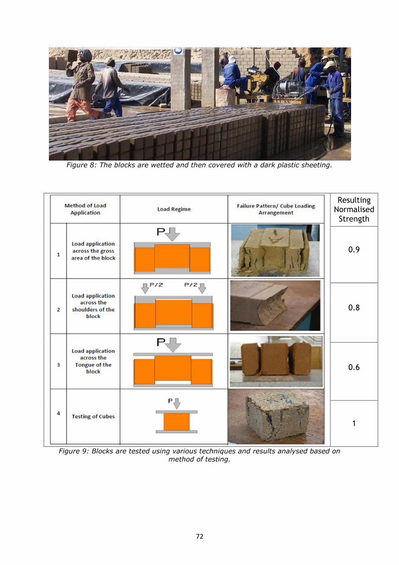
72
Figure 8: The blocks are wetted and then covered with a dark plastic sheeting.
Resulting Normalised Strength
0.9
0.8
0.6
1
Figure 9: Blocks are tested using various techniques and results analysed based on
method of testing.

73
Table 1: Soil particle fractions
GRAVEL FRACTION:
coarse gravel - 60 to 20 mm
medium gravel - 20 to 6 mm
fine gravel - 6 to 2 mm
SAND FRACTION: coarse sand - 2 to 0.6 mm
medium sand - 0.6 to 0.2 mm
fine sand - 0.2 to 0.06 mm
SILT FRACTION: coarse silt - 0.06 to 0.02 mm
medium silt - 0.02 to 0.006 mm
fine silt - 0.006 to 0.002 mm
CLAY FRACTION: passes the - 0.002 sieve
References
[1] Joe Mapiravana & Naalamkai L Ampofo-Anti, Prioritising building materials research
and development in the delivery of subsidised housing in South Africa: NHBRC
Housing Conference 2011.
[2] Anifowose, A.Y.B. 2000. Stabilisation of lateritic soils as a raw material for building
blocks: Bulletin of Engineering Geology and the Environment, 58: 151-157
[3] Arumala, J. O and Gondal, T. (2007). Compressed earth Building Blocks for
Affordable Housing. RICS, London, COBRA 2007. ISBN: 9781842193570
[4] Lunt, G. 1980. Stabilised Soil Blocks for Building. UK: Department of the
Environment, overseas division

74

75
TECHNICAL PAPERS

76

77
CASSAVA PEEL ASH: AN EMERGING POZZOLANIC MATERIAL
Kolawole Adisa Olonade
Department of Civil Engineering, Obafemi Awolowo University, Ile-Ife, Nigeria
Brief author biography
Engr. Dr. Kolawole Adisa Olonade has a PhD in Civil and Environmental Engineering with
particular interest in Materials and Structures from University of Lagos, Nigeria. He is a
member of various professional bodies including the Technical Committee of Sulphate
Testing Resistance of RILEM. Dr. Olonade’s research activities involve utilisation of
various wastes in Nigeria for the production of cement-based products, contributing to
the reduction of construction costs and improving environmental sustainability. He is
currently an academic at the Department of Civil Engineering, Obafemi Awolowo
University, Ile-Ife, Nigeria.
Introduction
Recently, there has been growing interest in the use of agricultural wastes as partial
substitute of cement in concrete.
The use of pozzolanic materials is found in many ancient civilizations. More recent, in
Europe and the USA, there have been numerous massive structures built with the use of
pozzolan-cement mixtures [1]. Nevertheless, many researchers have demonstrated the
use of different agricultural wastes such as sugar cane straw ash, groundnut husk ash
etc. as pozzolans with positive results [2, 3]. However, the use of cassava peel ash (CPA)
as pozzolan is novel.
Nigerian cassava production is by far the largest in the world. Its annual production is put
at 51 million metric tonnes (mmt) [4]. Cassava peel (CP) is a by-product of cassava
processing for domestic or industrial uses. Adesanya et al. [5] reported that cassava peel
constitutes between 20-35% of the weight of tuber, especially in the case of hand
peeling. Based on 20 per cent estimate, about 10.2 mmt of cassava peels are generated
annually and 12 mmt is expected to be produced in the year 2020, when the cassava
production would have risen to 60 mmt.
Indiscriminate disposal of cassava peels (CP) due to gross underutilization as well as lack
of appropriate technology to recycle them is still a major challenge. Heap of cassava
peels ready for burning for no benefit in return is shown in Figure 1. Recycling the CP
into a more beneficial use in the construction industry is thus desirable. This will also
ensure environmental sustainability.
Materials and methods
Cassava peels were collected and activated by burning in furnace at temperatures of 500,
600, 700, 800, 900 and 1000 for 30, 60 and 60 minutes. Chemical content of ash

78
produced from each treatment was determined using XRF technique. Activation condition
that produced ash with higher amorphous silica and alumina was noted. This condition
was used to produce CPA that was blended with Portland cement at varying percentages
of 5 to 25% (5% interval) by weight of cement. Pozzolanic reaction between CPA and
calcium hydroxide (CH) was examined using the method used by Dwivedi et al. [6]
Mortar of mix ratio 1:3 by weight was produced and cast into a prism mould of size 40 ×
40 × 160 mm; mortar specimens were tested for strengths (compressive and flexural) as
prescribed by BS 4550-3.4-1978. Water binder ratio of 0.5 was used and fine aggregate
used was river sand of maximum nominal size of 3.18 mm.
Results and discussion
Chemical composition of CPA
Silica content of CPA increased with increase in both temperature and time of burning
(Table 1). Since amorphous silica is required, it was observed that the silica produced
from the CPA at temperatures of 800 and above formed ball-shaped particles that
could be considered as crystalline. This finding was similar to what Shinohara and
Kohyama [8] reported about RHA. This study found that CPA produced at activation
condition of 700 for 90 minutes produced combined silica and alumina greater that
minimum of 70% recommended and could be considered as the appropriate conditions to
obtain amorphous silica suitable for pozzolanic activity. The XRD spectrum of CPA at this
activation conditions contained one smeared peak with many short bumps and irregular
base line, suggesting that CPA was mainly amorphous with traces of crystalline form.
Pozzolanic reactivity of CPA and free lime determination
The reaction between CH and CPA was monitored at different periods of reaction (1, 2, 3,
and 4 hours). The results indicated that the amount of CH that reacted with CPA
increased as the reaction period increased. This response suggested a pozzolanic
reaction. To further confirmed this performance, quantity of free lime present in hydrated
cement-CPA mixture at different ages of 1, 3, 7, 14, 21 28 days was monitored. Within
24 hours, there was no appreciable difference in the amount of free lime produced for all
the samples when compared with normal cement hydration but the difference became
more manifested when the hydration period increased. Reduction in free lime content
observed would indicate that CPA reacted with excess lime. However, at 20 and 25% CPA
contents, the same quantity of free lime was produced (0.58 mol/dm3) indicating that
pozzolanic reaction between CPA and CH was more active when CPA proportion is not
more than 15%.
Compressive and flexural strengths of blended cement-CPA mortar
In Table 2, it is shown that as proportion of CPA in mixes increased, the strength
decreased for the first 28 days of curing. However, at 90 days of curing, the compressive
strength values of mortar cubes produced from 5, 10 and 15% CPA were 50.9, 50.05,
and 49.7 N/mm2, respectively which were 99.4, 97.7 and 97% of the normal mortar.
Since pozzolanic effect is usually appreciated at longer period of curing, there could be
further increase in strength for the blended cement - CPA mortar at above 90 days as
shown by the trend of the compressive strength of mortar containing up to 15% CPA.
Flexural strength characteristics of cement-CPA mortar beams exhibited similar pattern
to their corresponding compressive strength behaviour. Furthermore, the strength

79
activity indices of mortar containing up to 15% CPA was about 80%, greater than
minimum of 75% recommended for fly ash. This performance further suggested CPA
could be considered as pozzolanic.
Conclusion
Tests to investigate pozzolanic properties of CPA were conducted. The following could be
concluded from the study:
i. Cassava peels are available in large quantity in Nigeria and disposed for no benefit
in return.
ii. Cassava peel ash burnt at temperature of 700 for 90 minutes contained
amorphous silica in adequate quantity and state for pozzolanic reactivity.
iii. Blended cement-CPA mortar containing 15% proportion of CPA has strength
comparable with that of normal mortar.
iv. There is further need to study microstructure of hydrated cement-CPA mixture to
make more precise generalization.
Figures and tables
Figure 1: Heaps of cassava peels at a cassava processing centre in Ilaro, Nigeria [6]

80
Table 1: Effect of Calcining Temperature and Duration on Chemical Composition
of Cassava Peel Ash (CPA) and Ordinary Portland Cement (OPC) Temp. Time Oxides (%)
(0C) (min) SiO2 Al2O3 Fe2O3 CaO MgO SO3 K2O Na2O LOI
500
30
CP
A f
ro
m
un
wash
ed
CP
47.29 6.83 3.78 8.66 4.17 2.97 10.62 0.64 13.66
60 51.73 9.21 1.17 7.77 4.55 2.26 17.76 0.02 11.07
90 52.22 6.91 3.84 9.05 4.41 3.01 8.76 0.65 10.10
600
30 45.57 6.94 3.78 8.78 4.36 3.10 10.99 0.63 14.54
60 47.23 7.18 4.03 9.31 4.40 3.04 10.47 0.61 10.88
90 49.20 7.44 4.20 9.96 4.91 3.33 7.68 1.93 10.88
700
30 49.54 7.45 6.09 9.61 4.58 2.89 10.49 0.55 7.30
60 53.35 7.13 4.02 9.20 4.23 2.56 9.45 0.60 4.56
90 58.02 12.80 1.41 8.53 5.02 2.18 7.67 0.03 4.18
800
30 52.36 6.17 3.24 10.02 4.59 2.56 10.48 0.37 12.03
60 54.12 7.02 3.52 11.64 5.18 3.34 4.84 0.24 8.49
90 58.90 7.54 3.79 6.81 5.21 4.21 6.37 0.40 6.11
900
30 51.88 7.39 3.71 12.70 5.79 3.99 8.55 0.34 7.35
60 53.54 7.38 4.02 11.18 3.68 4.07 7.82 1.21 7.37
90 58.37 7.86 3.94 9.24 6.50 4.44 6.77 0.46 5.28
1000
30 51.13 6.89 3.21 8.20 6.50 4.34 7.88 0.03 6.10
60 52.34 8.45 2.98 9.89 5.67 3.45 6.77 1.23 3.67
90 59.95 8.71 3.89 8.69 5.38 3.60 7.28 0.37 4.73
700 90 *wcp 52.57 6.94 3.78 8.78 4.36 3.10 10.99 0.63 7.54
OPC 19.99 5.49 3.00 63.32 1.45 0.34 0.08 0.09 3.96
Table 2: Compressive and Flexural strengths of cement-CPA mortar
CPA Content
(%)
Compressive Strength (N/mm2) Flexural Strength (N/mm2)
Curing Age (Days) Curing Age (Days)
7 28 56 90 7 28 56 90
0 34.4 41.1 46.7 51.2 5.7 6.4 6.8 7.1
5 32.2 40.1 45.5 50.9 5.3 6.2 6.7 6.9
10 32.0 39.8 44.4 50.5 5.2 5.9 6.4 6.8
15 29.7 38.7 43.6 49.7 5.1 5.8 6.2 6.7
20 26.1 37.1 39.0 39.5 4.7 5.7 5.8 5.9
25 16.1 19.2 19.4 19.7 2.1 3.5 3.7 3.8
References
[1] Wilson .J.W. and Ding Y.C (2007). "A Comprehensive Report on Pozzolanic
Admixtures, the Cement Industry, Market and Economic Trends and Major
Companies operating in the Far East, with Reference to Pagan Island" prepared for
the Secretary, Department of Public Lands, Commonwealth of Northern Mariana
Islands. 4-33.
[2] Frías, M., Villar Cociña, E., Valencia-Morales, E., (2007). “Characterisation of sugar
cane straw waste as pozzolanic material for construction: Calcining temperature
and kinetic parameters”, Journal of Waste Management, 27, 533-538.
[3] Ketkukah, T.S. and Ndububa, E.E. (2006). "Groundnut Husk Ash (GHA) as a
Pozzolana Material in Mortar", International Journal of Science and Technological
Research, 3(2), 209-214.

81
[4] Adesina, A. (2012). “Investigating Nigeria’s agricultural value chains”. A lecture
presented at the Bank of Industry’s Nigerian Investment Forum, London, Federal
Ministry of Agriculture and Rural Development, 1-48.
[5] Adesanya, O.A, Oluyemi, K.A., Josiah, S.J., Adesanya, R.A., Shittu, L.A.J., Ofusori,
D.A., Bankole, M.A. and Babalola, G.B. (2008). "Ethanol Production by
Saccharomyces Cereviasiae from cassava peel hydrolysate", The Internet Journal of
Microbiology, 5(1). 25-35.
[6] Salau, M.A. and Olonade, K.A. (2011) “Pozzolanic Potentials of Cassava Peel Ash”
Journal of Engineering Research, 16(1).
[7] Dwivedi, V.N., Singh N.P., Das, S.S. and Singh, N.B. (2006). "A new pozzolanic
material for cement industry: Bamboo leaf ash", International Journal of Physical
Sciences 1(3), 106-111.
[8] Shinohara, Y., and Kohyama, N. (2004). “Quantitative analysis of tridymite and
cristobalite crystallized in rice husk ash by heating”. Industrial Health. 42, 277-285.

82

83
COMPRESSIVE STRENGTH CHARACTERISTICS OF BAMBOO LEAF ASH
BLENDED CEMENT CONCRETE
John Temitope Kolawole
Department of Building, Obafemi Awolowo University, Ile-Ife, Nigeria
[email protected]; [email protected]
Kolapo Olubunmi Olusola
Department of Building, Obafemi Awolowo University, Ile-Ife, Nigeria
Brief author biography
John Temitope Kolawole received a university Bachelor of Science degree (B.Sc.) in
building at Obafemi Awolowo University and he is currently on a Master’s degree program
in Building Structures at the same university. He works as an academic at the
Department of Building, Obafemi Awolowo University, Ile-Ife, Nigeria. His research focus
is on sustainable alternatives to Portland cement in concrete production.
Introduction
In the cement industry, continuous attempts are being made to reduce the cost of
production of Portland cement and consumption of raw materials, energy expense,
protect the environment and enhance quality of cement. Ordinary Portland cement is one
of the most important building materials in terms of quantity produced [1, 2].
Since it is produced at a high temperature (15000C), it consumes a lot of energy,
emitting harmful gases and polluting the atmosphere (Metz et al., 2007), therefore, an
alternative to its use is a matter of urgency. One way of achieving this is to use certain
low cost materials for partial replacement of Portland cement in concrete production [3].
Also, there has been an increase in prices of houses over the last century, arising mainly
from escalating prices of building materials and has caused a shortfall in the provision of
adequate housing in Nigeria and globally [4]. Hence, alternatives to conventional building
materials have been focus of most researches recently and their suitability as local
materials for building construction purposes [5, 6, 7].
This work focuses on the use of bamboo leaf ash (BLA) as a partial replacement of the
conventional concrete binder namely cement. Also, the recent clamour for green,
sustainable buildings and eco-friendly construction materials aims at reducing the
production of harmful gases that pollutes the environment and minimizing waste that
litters the environment. Utilization of such agricultural waste like bamboo leaves serve as
an effective method of minimizing waste generated, saving energy and ensuring
sustainability in the built environment.

84
Materials and method
This research aimed at investigating the compressive strength properties of bamboo leaf
ash blended cement concrete with a view to ascertaining the suitability of bamboo leaf
ash as a pozzolanic material in concrete. The study experimentally determined the
characteristics of bamboo leaf ash, assessed the effects of varying percentage
composition of BLA and curing age on the compressive strength characteristics of BLA
blended cement concrete.
In determining the compressive strength, a total of 72, 100mm x 100mm x 100mm
concrete cubes were cast from mixes containing BLA contents of 0%, 5%, 10%, 15%,
20% and 25% as partial replacement for ordinary Portland cement (OPC). Bamboo leafs
collected were sun dried and thereafter burnt into ashes in a drum and spread on a clean
removable surface for quick cooling. The resulting ashes was then grinded and sift with
212 µm sieve and thereafter burnt further in a furnace up to 8000C. A targeted strength
of 25 N/mm2 was adopted to determine the proportion of the different components.
Manual mixing was done after which slump test was carried out in testing the workability
of the mixed concrete before casting. Water curing was done for 7, 14, 28 and 56 days.
Three replicates were used. Experimental results gotten were analyzed using tables,
graphs and analysis of variance (ANOVA).
Various tests carried out include aggregates’ sample grading, moisture content and
relative density, BLA X-ray diffraction analysis, chemical properties of BLA, workability of
freshly mixed concrete and compressive strength test of cube specimens.
Results and discussion
A relative density of 1.50 was gotten for the used sand while 2.00 was gotten for the
granite. An X-ray diffractometer (XRD) using CuKα radiation based on De Bragg’s
principle was used allowing an error margin of ± 0.03, compounds detected include KO3,
Fe2O3, SiO2, TiO2 and TiO3. BLA chemical properties were also determined using X-ray
fluorescence (XRF), result gotten is displayed in Table 1. The result of the XRF is far
better than that of XRD.
Slump test carried out was to ensure that the mixed concrete achieves a desired medium
workability of value between 50 mm and 100 mm. It was done in accordance to the
requirement of BS EN 12350-2: 2009. No admixture was used to enhance workability. It
was observed that the higher OPC partial replacement with BLA, the higher the water
required to achieve required slump. This implies that BLA as a pozzolanic material
requires more water to facilitate its hydration. The average results of compressive
strengths gotten for various OPC partial replacements with BLA and different curing ages
in water are summarized in Table 2.
Table 2 shows that for all the cement replacement levels, there is an increase in
compressive strength with time (curing age). This is due to the fact that concrete
strength increases with age and BLA as a pozzolan reacts with lime [Ca(OH)2] produced
from the hydration process of cement to form Calcium Silicate Hydrate (CSH) mainly
responsible for concrete strength. In contrary, compressive strength of the blended
cement concrete reduces generally as the BLA content increase. However, concrete with
5% and 10% BLA content performed favourably than other replacement levels. Likewise,
Fig. 1 below affirms these statements. But BLA content of 10% performs best after that
of the control with its plotline slightly above that of 5% and a R2 of 0.984. Hence, 10%

85
BLA can be taken as optimum, implying that ordinary Portland cement can be effectively
replaced with 10% bamboo leaf ash in concrete production.
Conclusion
By and large, observed results showed that:
The higher the BLA content, the higher the water/cement ratio required to achieve
required workability.
The higher the percentage replacement of cement with BLA, the lower the
compressive strength characteristics of the resulting concrete.
The optimum replacement percentage is 10% and the pozzolanic effect of the BLA
takes maximum effect at the later days of hydration (28 and 56 days).
Hence, BLA blended cement concrete is suitable for construction purposes when
later days strength is required.
Figures and tables
Table 1: Chemical properties of bamboo leaf ash (BLA) used.
Table 2: Compressive strengths of BLA blended cement concrete at various ages.
BLA (%) Compressive strength (N/mm2)
7 days 14 days 28 days 56 days
0 17.96 22.68 26.46 28.46
5 16.42 19.70 22.72 26.22
10 18.34 19.90 22.78 26.46
15 12.08 14.46 16.42 20.10
20 9.34 11.16 13.54 16.48
25 5.36 7.10 10.26 12.74
Elemental
Oxides
SiO2
(%)
Al2O3
(%)
Fe2O3
(%)
CaO
(%)
MgO
(%)
SO3
(%)
K2O
(%)
Na2O
(%)
Mn2O3
(%)
Cr2O3
(%)
P2O5
(%)
TiO2
(%)
LOI
(%)
BLA 72.97 2.85 2.31 4.98 1.23 0.55 6.07 0.00 0.41 0.05 2.37 0.41 4.20

86
Figure 1: Variation of compressive strength with curing age at various BLA content.
References
[1] Mehta, P.K. and Monteiro, P.J.M. (2006) Concrete: microstructure, properties and
materials, 3rd edn, McGraw-Hill, New Delhi.
[2] Hosseini, M.M., Yixin, S. and Whalen, J.K. (2011) Biocement production from
silicon-rich plant residues: perspectives and future potential in Canada. Biosystems
Engineering, 110(4).
[3] Dwivedi, V.N., Singh, N.P., Das, S.S., Singh, N.B. (2006) A new pozzolanic material
for cement industry: bamboo leaf ash. International Journal of Physical Sciences,
1(3), 106-11.
[4] Olusola, K.O. and Adesanya, D.A. (2004) Public acceptability and evaluation of local
building materials for housing construction in Nigeria. Journal of property research
and construction, 1, 83-98.
[5] Dipayan, J. (2007). A new look to an old pozzolan: clinoptilolite-a promising
pozzolan in concrete. Paper presented at the 29th annual conference of cement
microscopy, Quebec city, Canada.
[6] Metz, B., Davidson, O., Bosch, P., Dave, R., & Meyer, L. (2007). Climate change
2007 Mitigation of climate change, Intergovernmental Panel on Climate Change,
Geneva (Switzerland), (Working Group III).
[7] Umoh, A.A., Alake, O., Babafemi, A.J., Olasunkanmi, O.F. (2013). Assessing the
performance of ternary blended cement concrete incorporating periwinkle shell and
bamboo leaf ashes. Civil and Environmental Research, 3(1), 26-35.
R² = 0.8049
R² = 0.9293
R² = 0.984
R² = 0.9691
R² = 0.9666
R² = 0.9382
5
10
15
20
25
30
5 15 25 35 45 55
Co
mp
ress
ive
Stre
ngt
h (
N/m
m2 )
Curing Age (days)
0% BLA
5% BLA
10% BLA
15% BLA
20% BLA
25% BLA

87
PHYSICAL AND MECHANICAL PROPERTIES OF A PORTLAND CEMENT
BLENDED WITH SILICA UNDER SATURATED CARBONATITIC LAVAS AS
NATURAL POZZOLANS
Apollo Buregyeya
University of the Witwatersrand, Johannesburg, South Africa
[email protected]/ [email protected]
Brief author biography
Apollo Buregyeya is a PhD student at the School of Civil and Environmental Engineering
of the University of the Witwatersrand, Johannesburg, South Africa. His research focus is
on characterisation of volcanic rocks as mineral admixtures in Portland cement concrete.
He holds a bachelor of science in civil engineering and a master of science in civil
engineering, both degrees attained at Makerere University, Kampala, Uganda. Apollo also
works at Makerere University, Kampala, Uganda as an assistant lecturer in the
Department of Civil and Environmental Engineering.
Introduction
As part of a PhD study into characterisation of natural pozzolana from the East African
rift system, this study aims to evaluate the physical and mechanical characteristics of
silica undersaturated ultrapotassic kamafugites and carbonatitic lavas of the Toro-Ankore
geological region when used as supplementary cementitious materials in Portland cement
concrete. Toro-Ankore geological region is located in the Albertine rift, of the East African
rift system (Fig. 1). The East African rift system (Fig. 1a) is composed of the Eastern arm
running from the Red sea up to Southern Africa and the Western arm that starts from the
North Western Uganda and joining the Eastern arm in the South of Tanzania.
Petrology of volcanic rocks in East Africa
The petrology and geochemistry of volcanic deposits in the different volcanic zones of the
East African rift system has been extensively studied [1-6, 13-14]. The deposits were
found to be predominantly carbonatites and alkali volcanic rocks. The Western arm shows
a variation in the chemistry of volcanic deposits from basaltic volcanic deposits that are
weak in alkalinity to strongly silica undersaturated high potassium carbonate-rich
carbonatites and kamafugites. The Eastern arm of the rift system is dominated by
sodium-rich dolomite and calcite deposits of carbonatite complexes with carbonatite,
nephelinite, nepheline syenite, ijolite and phonolite rock series. The Western rift is
dominated by katungite, mafurite, ugandite, basanite, leucitite, nephelinite, and melilitite
rock series. The occurrence and location of these deposits is mainly associated with the
rift system [3]. The deposits are distinctly different form each other following their
individual points of volcanic eruption. The estimated volume of volcanic deposits in the
western branch of the East African rift system is approximately 100,000 cubic kilometres
[4] while that for the eastern branch ranges from 220,000 to over 900,000 cubic
kilometres [5, 6].

88
Justification for the study
The pressure of an increasing housing infrastructure demand experienced in developing
regions of the world is characteristic of increased stress on the environment as
manifested in the rates of deforestation, degradation of natural resources, growth of
informal settlements, to mention but a few. Most of sub-Saharan Africa lies in this
classification. Portland cement concrete is still the preferred option to meeting the
housing infrastructure deficit obtaining in sub-Sahara Africa. Concrete is however still
unaffordable by the majority in sub-Sahara Africa partly because the manufacture of the
active ingredient in concrete, Portland cement, is costly due to its association with high
energy consumption [7, 8]. A number of researches have shown that utilisation of easily
accessible supplementary cementitious materials (SCMs) that require minimal processing
significantly reduces the cost of cement [8, 9, 10]. The impetus of this study is that the
abundant volcanic deposits in the East African rift system can be explored (characterised
and tested) to provide a viable and affordable option to make concrete for addressing the
challenge of providing housing infrastructure in the region.
For a material to qualify as an SCM, it should have a suitable chemical and mineralogical
composition, be easily accessible, environmentally responsive and of relatively low cost
[9]. The problem of high variability of important physicochemical properties in volcanic
rocks has been addressed partly by the availability of highly pozzolanic industrial by-
products such as fly ash, silica fume and blast furnace slag. The production of these
materials is a controlled process that delivers SCMs with largely consistent
physicochemical characteristics [9]. The increase in demand for SCMs coupled with a
conflicting reduction in their production due to technological advancements in
manufacturing processes and adaptation to more sustainable policies [7, 8] has led to a
renewed demand for research to characterise natural pozzolana deposits. Recent
research trends on alkali-activation of pozzolanic industrial waste such as silica fume and
GGBS [9, 11] postulates a future shortage of these materials. Furthermore, most
developing and under-developed countries around the world are deficient of the highly
pozzolanic industrial waste yet sufficient in volcanic rocks deposits that can be put to use
as SCMs [12].
Much of published research characterising the volcanic deposits in the East African rift
system is in a geological domain [1-6, 13, 14]. Not much has been published on the
engineering applications of these materials that are already being utilised by cement
companies operating in the East African region to produce pozzolanic cements. In the
majority of cases, research findings of multi-national cement companies are hoarded by
individual companies and hence do not support the growth of local skills and
competences. The few existing studies on characterisation of natural pozzolana as SCMs
in East Africa are limited in scope and have empirical observations that limit the extent of
their beneficial application. This has therefore led to limited beneficiation of the abundant
natural material in the region. The natural pozzolana blended cements produced in the
East Africa region are mainly used in relatively simple structures with no significant public
importance that would demand actual field performance studies of the pozzolana blended
cements. Major infrastructure developments in the East African region rely mainly on
imported cements and there is a general disdain for structural application of the locally
produced pozzolanic cement by design consultants. Concrete technology practices in the
East African region further complicate any intention to evaluate actual performance of
these blended cements and therefore the consumer only relies on the information
supplied by the manufacturer or his agents to apply these cements. This level of

89
uncertainty leads to expensive designs, a factor that contributes to the high cost of
construction.
Materials and methods
A study of physical and mechanical properties of volcanic materials that influence their
performance as SCMs in Portland cement concrete is partly petrological and partly
engineering. Understanding the physicochemical characteristics from the petrological
perspective and then projecting the observed characteristics to performance of the SCMs
in Portland cement concrete presents an opportunity for prognosis in application of the
volcanic materials as SCMs. Four samples of the volcanic tuff sourced from different
locations in the study area have been pulverised to Blaine fineness ranging from 3000 to
5000 cm2/g. Characterisation tests have been conducted on the samples to evaluate
grindability, chemical composition, pozzolanic activity, water demand, setting time and
fineness optimisation for strength development. Pozzolanicity has been tested according
to EN 196-5 (Frattini test) and strength activity index tests (ASTM C 311) for mortar
prisms at 7, 28, 56 and 90 days is ongoing. Isothermal conduction calorimetry was
utilised to advance more understanding of the interaction of the different natural
pozzolana samples with Portland cement. Laser diffraction technique was utilised in
particle size analysis of the different powder samples. A polarised light microscope
(Eclipse LV100 polarizing) was used to characterise particle shape and texture and
together with X-ray Diffraction (XRD) analysis to evaluate the glass content,
mineralogical composition and mineralogical changes due to thermal destabilisation of
the volcanic tuffs.
Conclusions
The presence of the volcanic materials increased water demand while the setting time
was reduced.
Preliminary results show the Frattini test to be unreliable in testing pozzolanicity of the
samples. Moreover, samples 1 and 2 (Table 1) fail the ASTM C618 [15] minimum
requirement of the sum of silica, alumina and iron oxide composition of 70% but exceed
the minimum strength activity minimum requirement.
The silica undersaturated samples are characteristically high in CaO reaching 25% of
total oxide composition in studies conducted with XRF. The role of limestone and soluble
alkalis in influencing hydration will be investigated and is not part of the current scope.
The study advances the need to evaluate cement extenders more on the basis of their
resulting performance in concrete.

90
Figures and tables
Table 1: Chemical analysis and physical characteristics of kamafugites and carbonatites
Parameters/% oxide composition
Sample 1 (S1)
Sample 2 (S2)
Sample 3 (S3) Sample 4 (S4)
CEM 1 52.5R
Source Fort Portal Katwe-Kikorongo
Kataara - Bunyaruguru
Rushasha - Bunyaruguru
Afrisam
Loss on Ignition (LOI)
13.57 16.55 10.43 10.38 0.09
SiO2 35.81 41.59 56.78 52.06 20.33
Al2O3 9.29 8.87 8.67 9.29 4.41
Fe2O3 13.73 12.35 8.19 8.99 2.53
CaO 25.19 19.78 8.87 11.19 65.19
MgO 5.49 6.44 6.95 7.37 1.80
K2O 1.07 2.82 4.69 4.39 0.48
Na2O 1.8 1.13 0.3 1.01 0.09
P2O5 2.75 1.97 1.07 1.24 0.08
TiO2 2.31 3.33 2.78 2.44 0.41
Mn2O3 0.42 0.27 0.16 0.17 0.10
Cr2O3 0.02 0.02 0.05 0.03 0.01
V2O5 0.05 0.06 0.05 0.05 0.01
Total XRF 97.93 98.65 98.56 98.23 95.42
Specific gravity 2.75 2.63 2.38 2.55 3.14
Water demand 30.75 32.00 30.70 33.14 30.70
Initial Setting time (min) 80:20 ratio
200 200 190 200 200
Final Setting time (min) 80:20 ratio
245 255 246 256 286
Initial Setting time (min) 65:35 ratio
180 180 170 191 201
Final setting time (min) 65:35 ratio
245 255 225 306 261
7 day mortar strength
38.9 42.6 40.0 40.7 44.0
d(10%) 0,85 0,68 0,85 0,67 1,42
d(50%) 14,70 11,39 21,90 10,23 12,53
d(90%) 99,81 82,19 178,72 81,69 32,07

91
Figure 1: (a) A sketch map of eastern Africa showing the rift system and occurrence of
lava deposits. The Albertine rift or the western branch is composed of Toro-Ankore,
Birunga and South Kivu series. The hairy lines represent the main rift faults. (Map
adapted from Tappe et al [13]) (b) Location of volcanic tuff deposits in the Toro-Ankore
series (after Tappe et al [13]). Carbonatites are mainly located in the northern deposits
of Fort Portal (FP) and Ndale (ND) (tappe et al [13]) while Kamafugites occupy
Katwe_Kikorongo (KK), Bunyaruguru (Bu) and Katunga (KT) deposits.
References
[1] Rosenthal A., Foley S. F., Pearson G. D., Nowell M. G., Tappe S., (2009),
“Petrogenesis of strongly alkaline primitive volcanic rocks at the propagating tip of
the western branch of the East African Rift”, Earth and Planetary Science Letters
284, Elsevier B. V., pp 236-248.
[2] Barker D. S, and Nixon P. H, (1989), “High-Ca, low-alkali carbonatite volcanism at
Fort Portal, Uganda; Contrib. Mineral. Petrol. 103: pp 166-177; Springer.
[3] Jones P. Adrian, Genge Mathew, Carmody Laura, (2013), “Carbon in Earth:
Carbonate melts and Carbonatites”, Reviews in Mineralogy and Geochemistry, Vol.
75 pp 289-322; The Mineralogy Society of America, ISBN 978-0-939950-90-4.
[4] Kampunzu A. B., Mohr P., (1991), “Magmatic evolution and petrogenesis in the East
African Rift system”, in Kampunzu A. B., Lubala R. T.; Magmatism in Extensional
Structural Settings: the Phanerozoic African Plate. Springer, Berlin, pp 85-136.
[5] Williams L.A.J., (1972), “The Kenya Rift volcanic: a note on volumes and chemical
compositions”, Tectonophysics Vol. 15 pp 83-96.
[6] Morley C.K., (1999), “Tectonic evolution of the East African Rift system and the
modifying influence of magmatism”, a review, Acta vulcanologica Vol. 11 (1), pp 1-
19.
[7] Damtoft J S., Lukasik J., Herfort D., Sorrentino D., Gartner E M., (2008),
“Sustainable development and climate change initiatives”, Cem Concr Res, 38, 115-
127. http://dx.doi.org/10.1016/j.cemconres.2007.09.008.
[8] Schneider M., Romer M., Tschudin M., Bolio H., (2011), “Sustainable cement
production- present and future”, Cem Concr Res, 41, 642-650.

92
[9] Snellings R., Mertens G., Elsen J., (2012), “Reviews in Mineralogy and
Geochemistry: Supplementary Cementitious Materials”; Applied Mineralogy of
Cement & Concrete, Vol. 74. Pp. 211-278, Mineralogical Society of America.
[10] ACI committee 232 report, (2001), “Use of raw or processed natural pozzolans in
concrete”, ACI 232.1R-00, American Concrete Institute, Farmington Hills, Mich.
[11] RILEM TC224 AAM (2014), “Alkali-Activated Materials: State-of-the-Art Report”,
Springer ISBN978-94-007-7671-5.
[12] Blanco Varela M.T., Martinez Ramirez S., Erena I., Gener M., Carmona P., (2006)
“Characterisation and pozzolanicity of Zeolitic rocks from two Cuban deposits.
Applied Clay Sciences 33 pg 149 - 159, Elsevier.
[13] Tappe S., Foley S. F., and Pearson D. G., (2003), The Kamafugites of Uganda: a
mineralogical and geochemical comparison with their Italian and Brazilian
analogues, Period. Mineral. 72 pp51-77.
[14] Holmes A. (1942), “A suite of volcanic rocks from south-west Uganda containing
kalsilite (a polymorph of KAlSiO4)”, the Mineralogical Magazine and Journal of the
Mineralogical Society, Vol.XXVI, No.177, pp 197-217.
[15] ASTM C618, (2005) “Standard specification for coal fly ash and raw or Calcined
natural pozzolan for use in concrete”, American society for testing and materials.
West Conshohocken, PA, ASTM International.

93
PERFORMANCE OF TERNARY CEMENTITIOUS BINDER SYSTEMS
INCORPORATING UNTREATED AND TREATED POZZOLANIC MATERIALS
Bartosz Bobkowski
HTW University of Applied Science in Cooperation with Federal Institute for Materials
Research and Testing, Berlin, Germany
Brief author biography
Bartosz Bobkowski received the Bachelor of Engineering (B.Eng.) in structural
engineering at the FH Mainz. He is currently writing his Master thesis and will become
Master of Science end of 2015. After having finished his Bachelor, Bartosz worked for two
years as a site engineer on a Tram railway project in Edinburgh (Scotland). His interest
for concrete brought him to the above mentioned institute and the possibility to start
testing a promising supplementary alternative cementing material which is rice husk ash.
Introduction
The way concrete is used changed rapidly in the last decades. Originally concrete
consisted of three components (cement, water, gravel/sand mixture). Nowadays it has
evolved to a 5 component system (cement, water, gravel/sand mixture, supplementary
cementitious materials and additives) which do not only concentrate on strength but also
aspects like workability, durability and sustainability.
Concrete is the most used material in the world. Out of the 29 countries with the highest
growth in the demand for concrete, 16 nations are located on the African continent.
Particularly Sub-Saharan Africa shows massively emerging markets, where only concrete
can satisfy the demand for decent housing and infrastructure.
Use of cement in Africa
The origin of Portland cement was around 170 years ago in Great Britain. Since then,
concrete technology has spread out to Europe, the United States, and Japan. Except for
South Africa, most Sub-Saharan African Countries where not involved in the development
and research on cement and concrete. As a consequence the standards for concrete were
assimilated to the needs of the above mentioned initial countries, underestimating some
specialities like the infrastructure, high temperatures and humidity in African countries.
Even the existing standards and guidelines are yet relatively low implemented in
construction activities. Furthermore many common practices like ready-mix concrete
can’t be used due to a shortage of sufficient concrete mixing plants and the missing
infrastructure in most parts of Africa. On-site mixing can be considered as the usual way
to work on construction sites.
The commonly used supplementary cementitious materials, are based on inert,
pozzolanic hydraulic active materials, they often derive from industrial processes.
Unfortunately most Sub-Saharan African countries do not have enough of the needed
industries at the moment to provide the by-products needed for the cement industry.

94
The main ingredient for concrete will still be ordinary Portland cement. Cement plants are
scarce in Africa. Prices for cements are extremely high and demands cannot be covered.
Most sub-Saharan countries need to import cement from countries like China, Indonesia
and South Africa. The price can be as high as in Europe and locally even three times
higher. Due to Chinas powerful dominance on the market, it is doubtful that new industry
cement production can compete in price and quality. The worldwide use of Portland
cement concludes in an emission of over 2.6 Billion tons of CO² per year – with an
increasing tendency. Every year, 15 Billion tons of raw materials are used for concrete
aggregates and cement making. The production of one ton cement nearly equals one ton
of Carbon dioxide that disperses into the environment and therefore noticeably
contributes to an environmental pollution.
Creating an alternative
All those aspects force African economy to consider more modern standards, which
incorporate the best and newest technology in an adequate way. Therefore it should be
considered a unique opportunity to develop innovative African concrete technologies.
Consequently, in Africa there is pressure to save as much cement as possible. One
option could be the reduction of clinker content by using local supplements.
Africa is endowed with huge deposits of natural pozzolans, limestone or gypsum,
most of it existing along the eastern and western lift valleys of central Africa. By-
products from the agricultural industry like rice-husk ash, bagasse ash or stabilizers like
Cassava, maize, or potato starch can also be used as a supplement.
Blending reduces the costs and produces more environment friendly material, but also
improves the concrete performance by synergetic combination of the constituents.
One of the possible promising supplements is rice husk ash (RHA). After harvesting and
milling of rice, there is one main residue: the husk. Tanzania for example, the leading
rice producer in East Africa, produces about 1.1 million tonnes of rice, which equals over
300,000 tonnes classified as waste, not knowing about the commercial value. The by-
product has negligible protein content and therefore is not considered for livestock
feeding, RHA at proper incineration conditions is found to contain 85 – 95% amorphous
silica with high pozzolanic properties suitable for cement replacement. This available
natural resource could be utilized to improve the livelihoods of many people. In very
small scale projects rice husk is already used for burning bricks, create affordable
building material by mixing clay or cement with RHA
A set of studies have been realised using RHA in concrete made with recycled concrete
aggregates. With the use of approximately 50% of recycled concrete and 15% RHA
almost the same compressive strength was achieved as the representative sample using
a conventional concrete mix with natural aggregates and without RHA. Other studies
using RHA incinerated in different temperatures showed similar outcomes. The maximum
compressive and flexural strength could be seen at a reduction of around 10-15% of OPC
by RHA. Diverse side effects have been found using concrete containing RHA, like
reduced permeability, increased corrosion resistance and increased durability.
Furthermore it was found that this concrete has a high water demand because it has a
higher surface area than OPC, hence tends to absorb water faster.

95
Objective of the Master thesis
Those works on RHA concrete offer a high potential for further investigation. Within the
context of the master thesis the performance of rice husk-ash (RHA) will be evaluated
with regards to its use as a binder replacement for ordinary Portland cement (OPC).
Since RHA is assumed to show superior behaviour to OPC, it should further be evaluated
how far the use of RHA can help to reduce even higher amounts of OPC by replacing it
with an inert limestone filler material. The performance should also be compared to other
alternative materials that can be feasible for Sub-Saharan Africa.
The study will comprise evaluations of the cementitious systems containing RHA with
regards to:
- Mechanical properties and pozzolanic reactivity
- Early hydration
- Workability
- Interactions with water reducing admixtures
Adopted solutions for the African market could be in future cementitious pre-mix binder
compounds for concrete or even pre-mix binder compounds for self-compacting concrete.
These solutions already include cement, well-adjusted fines and admixtures as required.
They would need some more effort on site, which is considering the low labour costs no
big problem. But they do not require high labour skills and are able to perform reliable
regardless of most negative factors.
Knowing more about this interesting supplementary cementitious material RHA, could
help as well to thrive the development of those very practicable and suitable solutions for
the African continent.
References
[1] P.Padma Rao, Pradhan Kumar, Bhaskar Singh (2014): A Study on Use of Rice Husk
Ash in Concrete. In: International Journal of Education and applied research, Vol. 4,
Issue Spl-2, p. 75-81.
[2] Wolfram Schmidt, Charles Nmai, Apollo Buregyeya, u.a. (2013): Why does Africa
need African concrete? An observation of concrete in Europe, America, and Asia –
and conclusions for Africa. In: International Conference on Advances in Cement and
Concrete Technology in Africa, January 28-30, p. 1139 – 1147
[3] Akinkurolere O. O. (2013): Effects of Rice-Husk Ash as Partial Replacement for
Cement on Compressive Strength of Recycled Aggregate Concrete. In: International
Journal of Engineering and Technology, Vol. 3, No. 8, p. 777-780
[4] Noah Lusaka (2013): Various Uses of Rice Residues Across the East African Region.
In: Baobab, OPEN COLUMN2, March, p. 26-27
[5] Dr. Dipl.-Ing. Wolfram Schmidt and MSc. Nsesheye S Msinjili (2014): SCC: a
solution to the challenges of concrete construction in Africa. In: CONCRETE TRENDS
African Focus, p. 18-20
[6] MSc. Nsesheye Susan Msinjili, Dr. Dipl.-Ing Wolfram Schmidt (2014): Rice husk ash
as a constituent material for low-cost housing in Africa. In: CONCRETE TRENDS,
November, p. 46-47

96
[7] R. Nassingwa, N. M. Nangoku, W. Balu-Tabaaro, u.a. (2011): Workshop Cement
and Concrete for Africa – Proceedings. In: Spearhead Network for Innovative, Clean
and Safe Cement and Concrete Technologies, Berlin, 17th August 2011
[8] RAMADHANSYAH PUTRA JAYA, MOHD AL AMIN MUHAMAD NOR, ZAINAL ARIFIN
AHMAD, u.a. (2013): Properties of Mortar Containing Rice Husk Ash at Different
Temperature and Exposed to Aggressive Environment. In: Trans Tech Publications,
Advanced Materials Research, Vol. 620, p. 87-93
[9] Wolfram Schmidt, Naomi N. M. Hirya, Dubravka Bjegovic, u.a. (2012): Cement
technology in sub-Saharan Africa—Practical and scientific experiences. In: American
Ceramic Society Bulletin, Vol. 91, No. 5, p. 52-56
[10] Peter Wray (2012): Straight talk with Karen Scrivener on cements, CO2 and
sustainable development. In: American Ceramic Society Bulletin, Vol. 91, No. 5, p.
47-50

97
UTILISATION OF GUM ACACIA KAROO AS SET-RETARDING WATER-
REDUCING ADMIXTURE IN CEMENT MORTAR AND CONCRETE AT
OPTIMUM DOSAGE
Rose Mbugua
Tshwane University of Technology, Pretoria, South Africa
[email protected]; [email protected]
Ramadhan Salim
Tshwane University of Technology, Pretoria, South Africa
Julius Ndambuki
Tshwane University of Technology, Pretoria, South Africa
Brief author biography
Rose Mbugua is currently a Doctorate student at the Department of Civil Engineering at
Tshwane University of Technology in Pretoria, South Africa. She holds an M.Sc. in civil
engineering from Odessa State Academy of Civil Engineering and Architecture. She is a
Lecturer at Kenyatta University – Kenya. Her research focus is on admixtures, concrete
technology with new and emerging green materials, recycled construction materials.
Introduction
Concrete Admixtures have found wide application in construction industries. Globally, this
market is expected to be worthy $18.26 billion by 2019. Unlike Asia pacific region, which
is currently the leading consumer of chemical admixtures, usage of admixtures in Africa
is currently very low. However, it is expected to increase due to increase in construction
of new infrastructures, new residential buildings, roads, bridges and water retention
structures. Admixtures improve quality of construction producing more durable
structures. There is an opportunity to increase growth in usage of chemical admixtures
which is slow due to their high prices and lack of awareness in construction industry.
Ingredients that are added to the concrete batch other than water, aggregate or Portland
cement, in order to improve the properties of concrete, immediately before or during
mixing are known as admixtures. Admixtures have many beneficial effects on concrete
which include increased workability, hydration kinetics, water demand, improved
strength and better durability [1]. Chemical admixtures are commonly classified
depending on the function and effect on concrete. Type of admixture and extent of
interaction will influence the mechanical and physic-chemical properties of concrete.
Among the seven categories included in ASTM C494 [2] is type D which are set retarding
water reducing admixtures (SRWR). In this study, the effect of Gum Acacia Karroo (GAK)
as SRWR admixture in cement mortar and concrete was investigated. SRWR admixtures
are important for production of concrete in hot weather when placing and pumping. They

98
reduce water content by at least 5% but maintain a certain slump. Reduction in amount
of cement used can be realized by reducing water-cement-ratio (w/c).
GAK is a sticky natural gum which oozes from Acacia Karroo Haynes species. Acacia
Karroo grows wildly in Southern African countries and produces lower grade of gum.
Other species producing gum Arabic (GA) are Acacia Seyal or Senegal and comes mainly
from gum belt in Sub-Sahara countries in Africa [3]. It is of high quality and mostly used
in food industry.
GA is polysaccharide [4, 5] which contains similar sugars [6] like most lignosulphates
[7]. Khayat, [5] listed GA, xanthan gum and welan gum as natural polymers which are
soluble in water and increase cohesion and stability. GAK easily dissolves in water, has
low reactivity, does not interfere with blended product due to its pale colouration and
does not react with most minerals. Study conducted by [8] using Acacia gum from Seyal
species reported increase in compressive strength. Soluble sugar content of GAK yielded
70% of the precipitating mass which contained soluble sugars like glucose, fructose and
sucrose. Researchers have carried out studies using most of the natural gums but
literature on use of Acacia Karroo gum in concrete is scarce.
Significance of this study was to determine the effect of GAK on some mechanical
properties of cement mortar and concrete. Dosages of GAK at 0.7% and 0.8%wt (weight
of cement), identified to be within the optimum dosage, were used for the test and
compared with the control (sample without GAK).
Effect on compressive strength
Ordinary Portland cement CEM-I (grade 52.5) donated by Pretoria Portland Cement (PPC)
was used. GAK was picked from Pretoria Botanical Garden (GAKP). The tears were
picked, cleaned and sieved through a 200 µm sieve for cement mortar samples. For
concrete samples GAK was dissolved in part of gauge water for a night. Compressive
strength was performed on mortar samples according to South African Standard [SANS
50196-1]. The 0.7 and 0.8%wt dosage were chosen since they showed maximum
strength even without reduction of water. For all the dosages there was increase in
strength with age. Figure 1a illustrates compressive strength for 0.7% and 0.8% dosages
of GAK with w/c ratio of 0.5 while 0.7% RW and 0.8% RW represent w/c ratio of 0.4 for
cement mortars. For concrete (Figure 1b) 0.7% and 0.8% samples were prepared with
w/b ratio of 0.61 while 0.7RW and 0.8RW were prepared with w/b (water-bidder-ratio) of
0.5. The results indicate the dominate effect of water reduction on compressive strength
both in cement mortar and concrete. For cement mortar, there was a marginal difference
in compressive strength between the control, 0.7%wt and 0.8%wt dosages at 28 days.
However decreasing the w/c from 0.5 to 0.4 showed increase in strength by 3.4% and
8.3% for 0.7 and 0.8% dosages at 28 days. On the other hand, decreasing w/b ratio
from 0.61 to 0.5 increased compressive strength by 33.5% and 39.1% for 0.7RW and
0.8RW respectively for concrete samples. This increase in strength showed that GAK can
be used as a water reducer while maintaining certain slump for concrete and cement
mortar.
Rate of hydration by GAK
Retarding admixtures are basically in the same category as SRWR admixtures. Many
retarders reduce mixing water and many water reducers retard the setting of concrete

99
[9]. Tricalcium Silicate (C3S) and Tricalcium Aluminate (C3A) are the fastest hydrating
cement reactant groups and retarding admixtures are used to interfere with this reaction
delaying the setting time [10]. Delay can be attributed to adsorption of GAK on polymer
chains of cement grains and interference with the precipitation of various minerals into
solutions which can cause retarding effect on the rate of hydration and setting. GAK
delayed initial setting time by 1.7 hrs and 1.8 hrs for 0.7 and 0.8%wt dosage above
control respectively (Table 1). Final setting time increased by 4.6 and 4.4 hrs
respectively for 0.7 and 0.8% dosages at 230C
Setting time indicates the rate of hydration of cement. To have an idea of hydration
process TGA studies were carried out on cement mortars at 7 days at optimum dosages
(Figure 2). [11] carried out TGA tests to study hydration. Samples were heated between
30 0C to 1000 0C in Nitrogen at 100C per minute. Peaks below 3000C (Figure 2) were due
to decomposition of ettringite (C-H-S) and gypsum, between 4500 and 515 0C –
decomposition of Calcium Hydroxide (CH) (Hydration product) and 7400 to 850 0C was
decarbonation of calcium carbonate coming from clinker. Percentage of CH content,
calculated straight from TGA curves [12], was found to be 1.25% for 0.8% while 0.7%
dosage was at 1.58%. Lower percentage of CH at 0.8% dosage was an indication of
increased rate of hydration at that dosage as compared to 0.7% and thus higher
compressive strength. However the control had lower CH content at 0.92%.
Conclusions
Inclusion of GAK in cement pastes increased both initial and final the setting time thereby
affecting the rate of hydration. However further research should be carried out at
different conditions with different cements
Reducing w/c ratio by reducing the amount of mixing water increased compressive
strength of both concrete and cement mortar. This will result in reduced cost of concrete
with higher performance which leads to reduction of negative effects on environment by
reducing consumption of cement.
GAK is a good candidate for a SRWR admixture which is environmental friendly, non-toxic
and biodegradable producing green concrete.
Figures and tables
Table 1: Setting time of cement pastes.
Sample dosage (% wt.
Cement)
Initial setting time
(min)
Final setting time
(min)
No GAK
0.7%
191
291
261
536
0.8% 301 525

100
*RW= w/c of o.4 *RW=w/b 0f 0.5
Figure 1: Compressive strength: (a) mortar (b) concrete with different dosages and
different w/c ratio.
Figure 2: Thermogravemetric (TGA) analysis for cement mortar using different dosages
of GAK.

101
References
[1] V.S. Ramachandran, Concrete Admixtures Handbook, Second Edition ed., Noyes
Publication, U.S.A, 1995.
[2] ASTM C494 / C494M-13, ASTM International,West Conshohocken, PA, 2013,
www.astm.org.
[3] D. Verbeken, S. Dierckx, K. Dewettinck, Applied Microbiology and Biotechnology, 63
(2003) 10-21.
[4] N.A. Ademoh, A. Abdullahi, Research Journal of Applied Sciences, Engineering and
Technology, 1 (2009) 107-111.
[5] K.H. Khayat, Cement and Concrete Composites, 20 (1998) 171-188.
[6] S. Al-Assaf, G.O. Phillips, P.A. Williams, Food Hydrocolloids, 19 (2005) 661-667.
[7] V.S. Ramachandran, Concrete admixtures handbook: properties, science and
technology, Cambridge University Press, 1996.
[8] N.S. Abdeljaleel, Hassaballa, A.E. & Rahman, A. M., Innovative Systems Design
Engineering, 3 (2012).
[9] N.P. Mailvaganam, M. Rixom, Chemical admixtures for concrete, CRC Press, 2002.
[10] A.M. Neville, J.J. Brooks, Concrete technology, Longman Scientific & Technical
Harlow, 1987.
[11] Q. Zeng, K. Li, T. Fen-Chong, P. Dangla, Construction and Building Materials, 28
(2012) 468-475.
[12] A. Peschard, A. Govin, P. Grosseau, B. Guilhot, R. Guyonnet, Cement and Concrete
Research, 34 (2004) 2153-2158.

102

103
EFFECT OF FLY ASH--CYCLODEXTRIN COMPOSITES ON CONCRETE
PROPERTIES
Bolanle Deborah Ikotun
University of Johannesburg, Johannesburg, South Africa.
University of South Africa, Florida campus, Johannesburg, South Africa.
Brief author biography
Bolanle Deborah Ikotun is a doctorate student at the University of Johannesburg, South
Africa, in the department of Civil Engineering Science. She is also a lecturing staff at the
University of South Africa in the department of Civil and Chemical Engineering. Her
research focus includes concrete quality optimization techniques and investigation of
extenders as they affect mortar and concrete properties.
Introduction
The need for using industrial wastes as construction materials cannot be over
emphasized. The advantages range from the reduction in environmental pollution caused
by the industrial wastes to the reduction of construction cost as a result of the
incorporation of these wastes in construction. Fly ash (FA) is a promising industrial
waste, which has been used in concrete technology as a cement replacement and is
abundant in South Africa. However, its utilization is still limited compared to the quantity
(approximately 36 million tons per year) of the FA being generated by ESKOM (the major
South African electricity producer) as industrial waste. Therefore, there is a need to
increase the utilisation of the large amount of unused FA (approximately 94% of ash
generated) [1]. The exploitation of the unique chemistry of FA and modification of its
chemical structure are needed to make it more applicable in concrete, especially with a
view to improve early strength and durability developed when FA is used in concrete.
This study investigated the effectiveness of using cyclodextrin (an enzymatic modification
of starch) to beneficially modifies FA structure and hence increase the FA usage in
concrete technology.
In the previous studies reported by the author [2, 3], the chemical compatibility of FA
and cyclodextrin was confirmed and it was concluded that certain composites were
formed with fly ash-cyclodextrin interaction, which was envisaged to be useful in
improving fly ash behaviour in concrete production. Since these composites are relatively
new materials in concrete technology, indicative tests were performed using two
composites synthesis methods with different percentages of β-cyclodextrin (0.1%, 0.2%
and 0.5%) and 30% FA on concrete strengths (compressive and split tensile) and
durability (permeability, sorptivity and porosity) [4, 5]. Based on these tests results,
further investigations were carried out using the physical mixture composite, lower
percentages of β-cyclodextrin (0.025%, 0.05% and 0.1%), 30% FA and 50% FA. This
paper presents the effect of fly ash-β-cyclodextrin composites on setting time,
workability, compressive strength and permeability of concrete.

104
Materials and Experimental procedures
The main materials used are Class F FA, CEM152.5N cement and β-cyclodextrin (β-CD).
The FA was obtained from Matla ESKOM power station, South Africa. β-CD was obtained
from Industrial Urethanes (Pty) Ltd, South Africa. The cement type (CEMI52.5N) was
obtained from Pretoria Portland Cement Company (PPC), South Africa. FA-β-CD
composites mixtures were synthesized based on physical mixtures as explained
elsewhere [2]. The quantity of water used for the setting time test depends on the
amount of water that produced a consistent mix for each sample as described in
SANS50196-3 [6]. The concrete was mixed according to SANS 5861-1:2006. The
mixture proportion is shown in Table 1. Immediately after mixture, the slump test was
performed according to SANS 5862-1:2006 [7].
The setting time test was performed on cement paste based on the procedure described
in SANS 50196-3 [8] standard. Samples were mixed in a HOBART mixer, conforming to
SANS 50196-1 [9]. The compressive strength tests were performed according to SANS
5863: 2006 [10] on each 100 x 100 mm cube sample at 7, 14, 28, 90 and 180 curing
days. The permeability test was based on the durability index approach, which was
developed by Ballim and Alexander [11-13] at 28 and 90 days curing ages using discs
having a diameter of 68 mm and thickness of 30 ± 2 mm.
Results and discussions
The initial and final setting times of the cement pastes were affected by FA, β-CD and FA-
β-CD composites (Figure 1). An increase in both the initial and final setting times was
observed in binary samples while a further increase in both initial and final setting times
was observed in ternary samples. The β-CD showed a higher effect in increasing setting
time than FA. The higher the FA and β-CD contents, the greater the setting times
observed (Figure 1), with the highest of 696 minutes and 1420 minutes initial and final
setting times, respectively, observed for C50FA0.1CD sample.
The slump results presented in Table 1 show increase in slump with an increase in FA and
β-CD contents. Figure 2 shows that compressive strength increased with an increase in
curing age. The samples with 50% FA exhibited lower compressive strengths than other
samples. The C30FA sample showed increased compressive strength compared to the
control sample at 180 days curing period. A reduced compressive strength was observed
for C50FA samples at all curing ages compared to the control sample. The β-CD samples
(C0.025CD, C0.05CD and C0.1CD) showed an increase in concrete compressive strength
at all ages of curing, compared to the control sample. The composite samples containing
30% FA showed greater compressive strengths than the control sample at later curing
ages (90 and 180 days). However, composite samples containing 50% FA showed less
compressive strengths than the control sample at all curing ages.
The samples containing 0.1β-CD showed invalid permeability results and therefore
excluded from the discussion. The FA and FA-β-CD composite samples had a positive
effect on permeability as shown in Figure 3; decreased permeability was observed for
these samples at both curing ages, when compared to the control sample. The C50FA
sample showed a greater decrease in permeability than C30FA sample. Generally, the FA
and FA-β-CD composite samples had a better influence on concrete permeability at the
90 days curing age than at the 28 days curing age, which can be attributed to slower
pozzolanic reaction in these samples.

105
Conclusions
In general, the chemical structure of FA was improved with its interaction with
cyclodextrin. The FA-β-CD composite at lower percentages of FA (30%) and β-CD
(0.05%) improved FA concrete’s compressive strength at all ages. The study contributed
to the knowledge of FA structure modification using cyclodextrin and promoted the
continued inclusion of FA in concrete, which in turn should reduce the environmental
pollution resulting from FA on ash dams and carbon dioxide emitted during cement
production.
Figures and tables
Table 1: Mixture proportions for 1 m3 of concrete SA
Samples Cement Crusher sand (Kg)
Coarse aggregate
(Kg)
FA (Kg) β-CD (Kg)
Water (Kg)
W/B Slump (mm)
C 520.00 650 1000 0.00 0.00 208 0.4 30
C30FA 364.00 650 1000 156.00 0.00 208 0.4 40
C50FA 260.00 650 1000 260.00 0.00 208 0.4 55
C0.025CD 519.87 650 1000 0.00 0.13 208 0.4 40
C0.05CD 519.74 650 1000 0.00 0.26 208 0.4 55
C0.1CD 519.48 650 1000 0.00 0.52 208 0.4 135
C30FA0.025CD 364.00 650 1000 155.87 0.13 208 0.4 55
C30FA0.05CD 364.00 650 1000 155.74 0.26 208 0.4 70
C30FA0.1CD 364.00 650 1000 155.48 0.52 208 0.4 180
C50FA0.025CD 260.00 650 1000 259.87 0.13 208 0.4 80
C50FA0.05CD 260.00 650 1000 259.74 0.26 208 0.4 115
C50FA0.1CD 260.00 650 1000 259.48 0.52 208 0.4 200

106
Figure 1: Setting times of cement paste samples.
Figure 2: Compressive strength of concrete samples with 0.4 W/B.

107
Figure 3: Coefficient of permeability of samples.
References
[1] ESKOM 2014. ESKOM integrated report 2014,
http://integratedreport.ESKOM.co.za/pdf/full-integrated.pdf (CITED: 28/11/2014).
[2] Ikotun B.D., Mishra S., Fanourakis G.C.: Journal of Inclusion Phenomena and
Macrocyclic Chemistry 79, 311-317 (2014).
[3] Ikotun B. D., Mishra S., Fanourakis G. C.: Particulate Science and Technology,
Imprint: Taylor and Francis, Vol. 32, 360-365 (2014).
[4] Ikotun B. D., Fanourakis G. C., Mishra S.: RILEM proceedings PRO 95, conference
at Germany from 14-17/09/14. ISBN 978-2-35158-147-6, 55 – 64(2014).
[5] Ikotun B. D., Fanourakis G. C., Mishra S.: Proceedings of the first International
Conference on Construction Materials and Structures, 24-26/11/14, Johannesburg,
South Africa. ISBN 978-1-61499-465-7, 825 – 834 (2014).
[6] SANS50196-3:2006: Methods of testing cement Part 3: Determination of setting
times and soundness, ISBN 0-626-17598-4. Edition 2.
[7] SANS 5862-1:2006, Concrete tests-consistence of freshly mixed concrete – slump
test, Pretoria: South Africa Bureau of Standards.
[8] SANS50196-3:2006: Methods of testing cement Part 3: Determination of setting
times and soundness, ISBN 0-626-17598-4. Ed. 2.
[9] SANS 50196-1:2006: Methods of testing cement Part 1: Determination of strength,
ISBN 0-626-17596-8. Ed. 2.
[10] SANS 5863:2006: Concrete tests-compressive strength of hardened concrete,
Pretoria: South Africa Bureau of Standards.
[11] M.G. Alexander, Y. Ballim, J.M. Mackechnie, Concrete durability index testing
manual, Research monograph no. 4, (1999).
[12] M.G. Alexander, J.R. Mackechnie, Y. Ballim, Guide to the use of durability indexes
for achieving durability in concrete structures, Research monograph no 2, (2001),
5-25.

108
[13] M.G. Alexander, Durability indexes and their use in concrete engineering,
International RILEM Symposium on Concrete Science and Engineering: Print-ISBN:
2-912143-46-2, e-ISBN: 2912143586, 9 – 22.

109
DETERMINATION OF SUSTAINABLE ADDITIVES TO IMPROVE LOCAL
PORTLAND CEMENT FOR OFFSHORE CONSTRUCTION
Alice Titus
College of Engineering and Technology, University of Dar es salaam, Tanzania
Brief author biography
Alice Titus is the fourth year student of University of Dar es Salaam, College of
Engineering and Technology; she is pursuing Bachelor of Science in civil and structural
engineering. Her research project focus is on improving Portland cement by using
additives to increase the performance concrete in offshore construction.
Introduction
The construction industry is increasingly turning to the use of environmentally friendly
materials in order to meet the sustainable aspect required by marine infrastructures. This
is due inability of the ordinary Portland cement not performing well when subjected to
harsh environment. Hence, the development of suitable supplementary materials (fly
ash, natural Pozzolan or limestone powder) to improve Portland cement offers promising
signs for a change in the way of producing concrete which will sustain marine
environment [1].
Objectives of the research
The main objective of this study was to determine suitable additive to improve local
Portland cement to be used for construction of structures subjected to the marine
environment. To achieve this goal, the following specific objectives were done:
To determine the properties of the ingredients of mortar, fine aggregates, cement,
water, fly ash, pozzolan and limestone powder
To investigate unit weight of each prescribed mortar mix
To develop various cement sand mortars and determine the strength development
pattern, compressive strength through partial replacement of cement, water
permeability and determine the carbonation penetration.
The investigation and its findings can encourage the use of the new approach in use of
existing cement with readily available cementitious materials for casting specialized
onshore structures. This will result in promoting better quality construction and
innovative system in our construction industry.
The investigation undertaken will:
Confirm that, the partial replacement of fly ash, pozzolan and limestone will lead to
cheaper mortar/concrete than conventional plaster/concrete.

110
To help solve the problem of importing corrosion resistance chemical and special
cement for sea construction like geo polymer cement.
Compression test results
Compression strength test samples of size 70x70x70 mm were prepared of 1:3 mortar of
different proportional of blended Portland cement with different additives of 30%, 20%
and 10% replacement of cement. Distilled water was used for preparing mortar but
samples were cured in sea water. Their strength was determined for 2,7,14 and 28days.
The ratios of replacement cement were obtained experimentally where 20% replacement
by fly ash, 30%by natural pozzolan and 20% by limestone powder gave high
compressive strength compare to other replacement.
Then comparison of compressive strength of cement only and cement with partial
replacement by additive were done graphical as shown in the graph no 1.
The results shows that specimen containing 30% replacement contains high compressive
strength development compare to other. This is due to the content of SiO2 which dissolve
into water and form H2SiO4 which react with calcium hydroxide (the end product of
hydration reaction of cement) to form the grout paste of cement (calcium silicate
hydrate) which develop high strength to the specimen [2].
Also it shows the decrease of strength of the specimen containing cement only at day 14
this is due to the high amount of sulphate ion from the sea water which attacks the
constituent of cement like C3S and C3A.
Water permeability test results
This test was done to each proportion of mortar sample of 150x150x150 mm, this helps
to determine durability of mortar. Since the structure to be constructed in the sea water
has to be of low permeability of aggressive chemicals and to avoid the corrosion of
reinforced bar. Specimen were cured in normal water for 28days and left to dry for one
day then place in the water permeability machine for 48 hours. Then the specimens were
broken into two parts to determine the depth of penetration.
The experimental observations were done to the samples containing fly ash, natural
pozzolan and cement only and the result are shown in table 1.
The results show that the specimen containing natural pozzolan of 30% has low
permeability compare to other specimens followed by 30% replacement by fly ash and
this is due to the pozzolanic reaction which uses all calcium hydroxide which cause
porosity to the specimen.
But specimen containing cement only shows high permeability due to high amount of
porosity facilitated by high end product of hydration which is calcium hydroxide.
Carbonation test result
Each mix proportion sample of 28days carbonation test was conducted by using
phenolphthalein to determine the depth of penetration of carbon into the sample. This
helps to determine ability of the additive to resist the penetration of carbon-dioxide gas

111
which may cause corrosion of reinforcement. This test depends on the age of the
specimen and environments exposure. This test was conducted on the water permeability
sample after they had been tested for water penetration and being broken into two parts
to determine the depth of penetration of water, the solution was spread on the sample to
observe the change of colour.
If the sample turn into pink means sample is not carbonate but if does not turn into any
colour means the sample is carbonated.
Results shows that all specimen containing additive shows the change of colour to pink
soon after spreading the solution, where the colour remain unchanged for approximate
one month. But for the specimen containing cement only, the change of colour to pink
occur immediately after spread the solution but the next day the sample return to its
normal colour as shown in the picture no 1. This shows that cement only has low
resistance to carbon dioxide reaction compare to one containing additives. This is due to
high quantity of calcium hydroxide which reacts with carbon dioxide gas.
Analysis of result
According to the test observation above the following were the analyses
The use of natural pozzolan as additive of cement with replacement of 30% gives
the high compressive strength of 33N/mm2 at 28days of curing in sea and there
was the development of strength as the time increases.
Also limestone powder can be opted as additive, since it shows the high
compressive strength of 27.1N/mmm2 at 28 days of curing in sea and the strength
development pattern where increasing as time of curing increases.
Also during chemical reaction taking place between magnesium sulphate from sea
water and C3S (tricalcium silicate) and also with calcium hydroxide. There is the
production of gypsum (calcium sulphate) which has the role in cement to during
hydration to avoid the generation of high amount of heat and to prevent the C3S to
form mono-sulphate aluminates [2]. Hence there is possibility of reducing amount
of gypsum during the production of cement for off shore construction.
According to permeability test which were observed for natural pozzolan and fly
ash. Fly ash of 30% replacement shows small coefficient of permeability compare
to other followed by 30% replacement by natural pozzolan. But that does not draw
up conclusion that fly ash is suitable additive since it had small compressive
strength compare to natural pozzolan
Conclusion
Since the investigation is still in the progress, the conclusion cannot be done but there is
advantage of the expected result which is to obtain additive which will lower permeability
of Aggressive agents like chloride and sulphates and to increase performance of Portland
cement in concrete for offshore construction. Also to come up with ratio of most effective
additive partially to replace cement, this can be done on site or at the industry, hence
produce concrete structure which will be durable in that harsh environment.

112
Figures and tables
Figure 1: Comparison of strength of cement and additives replacement
Figure 2: shows unchanged colour specimen after carbonation test
0.0
5.0
10.0
15.0
20.0
25.0
30.0
35.0
0 5 10 15 20 25 30
com
pre
ssio
n s
tre
ngt
h in
N/m
m2
days
the graph of comparison of cement strength and additives replacement
fly ash 20%
cement only
natural pozzolan 30%
limestone powder 20%

113
Table 1: Water permeability test result
material type sample density after test
depth of penetration in
cm
coefficient of penetration K cm/sec x10^-5
average coefficient of penetration K cm/sec x10^-5
cement 42.5N 1 2.09 12.5 7.2
7.7 2 2.02 14.1 8.2
natural pozzolan 10%
1 1.98 2.6 1.5 1.4
2 2.03 2.2 1.3
natural pozzolan 20%
1 1.95 3.0 1.7 1.6
2 2.01 2.5 1.4
natural pozzolan 30%
1 2.04 2.0 1.2 1.0
2 2.07 1.6 0.9
fly ash 10% 1 2.12 3.5 2.0
1.9 2 2.13 3.0 1.7
fly ash 20% 1 2.13 3.0 1.7
1.7 2 2.12 2.9 1.7
fly ash 30% 1 2.08 1.2 0.7
0.6 2 2.07 0.9 0.5
References
[1] P.K.Mehta. concrete in marine environment.
[2] JayantD.Bapat. Mineral Admixtures in Cement and Concrete.
[3] Dr. Jeff Thomas, A. R. science of concrete.

114

115
PROPERTIES OF FRESH SELF-COMPACTING CONCRETE CONTAINING
SLAG
Omar Kouider Djelloul
Geomaterials Laboratory, Department of Civil Engineering, University of Blida, Algeria
Belkacem Menadi
Geomaterials Laboratory, Department of Civil Engineering, University of Blida, Algeria
Said Kenai
Geomaterials Laboratory, Department of Civil Engineering, University of Blida, Algeria
Brief author biography
Omar Kouider Djelloul Omar is a PhD candidate at the University of Blida, Algeria. He got
his university engineering degree in 2009 from the same university; and his Master by
research (Magister) in 2012 from the University of Blida. His main research interests are
self compacting concrete, cement replacement materials and recycling.
Introduction
Self-compacting concrete (SCC), is a highly flowable concrete with minimal segregation
that can flow into place under its own weight and no consolidation work at site [1].
One of the most important differences between SCC and conventional concrete is the
incorporation of mineral admixtures such as fly ash, silica fume, and ground granulated
blast furnace slag (GBFS) [2-5]. As these mineral additives replace part of the Portland
cement, the cost of SCC will be reduced especially as most mineral additives are
industrial by-products. GBFS is being widely used as a cement replacement in Portland
cement concrete because of its low heat of hydration, high sulphate and acid resistance
and higher ultimate strength[6, 7]. The improvement in strength and durability of GBFS
concrete is very sensitive to the fineness of GBFS and its glass content [8-10]. Higher
slag fineness increases the strength and significantly reduces the concrete
permeability and can greatly provide higher sulphate and acid resistance. However,
few studies have been investigated so far on the influence of GBFS fineness on the
workability of self-compacting concrete.
Experimental Program
This study, is aimed to investigate the effect of the slag content and its fineness on
the rheological properties of self compacting concrete. A total of ten concrete mixes
including the control mixes were prepared with 0, 10, 15, 20 and 25% of slag as
cement replacement with two different finenesses. The water to binder ratio was kept
low at 0.40 and binder content was maintained constant for all concrete mixtures. The

116
filling ability and deformability of SCC was determined with respect to slump flow. The
passing ability of SCC was assessed by L-box test. The segregation resistance was also
quantified by sieve test.
Results and discussion
Slump flow for self compacting concrete mixtures containing GBFS as partial cement
replacement with different finenesses are shown in Figure 1. It can be seen, from this
figure that slump flow values varied from 775 to 800 mm and 660 to 680 mm for SCC
mixtures with slag fineness 350 m²/kg and 420 m²/kg respectively. There is a slight
increase of slump flow of SCC mixes with increasing slag content in the case of
lower fineness (350 m²/kg). However, the contrary is noticed for higher slag fineness
(420 m²/kg). It should be noted that increasing slag content from 10 to 25%
improves the workability of concrete. The higher slump flow values are given by SCC
mixes with lower slag fineness. This increase of the fineness of slag lowers the
slump flow of all concrete mixtures containing slag. This reduction in slump flow
may be attributed to the high demand for the w/b ratio by the finer particles of slag.
Figure 2 shows the L-box test results filling and passing ability of SCC mixtures
with and without slag for different finenesses. It can be seen from this figure that
only SCC mixes content of 15 to 25 % with lower slag fineness (350 m²/kg) could be
used to produce SCC with an adequate passing ability. However, all the remained SCC
mixtures including SCC control present a risk of blocking. It should be noted that the
passing ability is more sensitive to the fineness of slag. Increasing the slag fineness
increased the risk of blocking of SCC mixtures as can be seen in this Figure. This could
be explained by the increase of the viscosity of the SCC mixes with increasing
slag fineness. The increase in viscosity tends to block the passing capacity of SCC
mixes through the three reinforcement bars of the L-box test setup. The results of
the resistance to segregation of SCC mixtures containing various amounts of GBFS
with different finenesses of 350 kg/m² and 420 kg/m² are illustrated in Figure 3. It can
be seen from this figure, that resistance to segregation of all SCC mixtures with
lower slag fineness decreases with increasing GBFS content. The results revealed that
SCC mixes content of 0 to 15 % with slag fineness 350 m²/kg possessed adequate
segregation resistance. An increase of fineness of slag led to segregation problem
for all SCC mixes as can be seen in Figure 3. This could be attributed to the higher
fineness of slag used in this investigation.
Conclusions
There is a slight increase of slump flow of SCC mixes with increasing slag content
in the case of lower fineness (350 m²/kg). However, the contrary is noticed for higher
slag fineness (420m²/kg)
Slag content of 15 to 20 % with lower slag fineness (350 m²/kg) could be used to
produce SCC with an adequate filling ability, passing ability and stability.
Increasing slag fineness affects significantly the rheology of self compacting concrete
mixes.

117
Figures and tables
Figure 1: Slump flow of SCC mixtures with different slag fineness.
Figure 2: L-box ratio of SCC mixes with different slag fineness.
0
100
200
300
400
500
600
700
800
900
0 10 15 20 25
Slu
mp
flo
w (
mm
)
Slag Content (%)
SSB = 350 m2/kg SSB = 420 m2/kg
0
0.2
0.4
0.6
0.8
1
0 10 15 20 25
L b
ox r
ati
o (
h2/h
1)
Slag Content (%)
SSB = 350 m2/kg SSB = 420 m2/kg
Fil
ing
ab
ilit
y
Blocking criteria 80%
420 m2 / kg 350 m
2 / kg
420 m2 / kg 350 m
2 / kg

118
Figure 3: Resistance to segregation of SCC mixtures with different slag fineness.
References
[1] Okamura H, and Ozawa K. Self-Compacting high Performance Concrete in
Japan. Second CANMET/ACI International Symposium on Advances In Concrete
Technology. Las Vegas, ACI, SP 159-2, 1995, pp 31- 44.
[2] Vejmelkováa E., Kepperta M, Grzeszczykb S, Skalin skib B, Cˇerny´B. Properties
of self-compacting concrete mixtures containing metakaolin and blast furnace
slag. Constr Build Mater,2011,25:1325–31.
[3] Boukendakdji O, Kenai S, Kadri E.H. and Rouis F. Effect of slag on the
rheology of fresh self-compacted concrete. Constr Build Mater, 2009, 23: 2593–
2598.
[4] Guneyisi E, Gesog˘lu M.O. and Zbay E. Effects of marble powder and slag on the
properties of self-compacting mortars. Mater Struct, 2009, 42:813–826.
[5] Gesoglu M, Guneyisi E, Ozbay E . Properties of self-compacting concretes made
with binary, ternary, and quaternary cementitious blends of fly ash, blast furnace
slag, and silica fume. Constr Build Mater,2009, 23, pp. 1847-1854.
[6] Khatib, J.M, Hibbert, J.J. Selected engineering properties of concrete incorporating
slag and metakaolin. Constr Build Mater;2005, 19:460–72.
[7] Kenai S, Hadj Sadok A, Menadi, B. Durability of concretes containing Algerian
slag. Tenth international conference on non-conventional materials and
technologies. Cali, Colombia; 2008, 12–14 November.
[8] Nakamura N, Sakai M, Swamy RN. Effect of slag fineness on the development of
concrete strength and microstructure. ACI Publication SP-132; 1992, p. 1343–66.
[9] Oner M, Erdog˘du K, Günlü A. Effect of components fineness on strength of blast
furnace slag cement. Cem Concr. Res;2003, 33:463–9.
[10] Neville, A. Properties of Concrete. 4th ed. London. Longman, London, 1995.
0
5
10
15
20
25
30
0 10 15 20 25
Seg
reg
ati
on
(%
)
Slag Content (%)
SSB = 350 m2/kg SSB = 420 m2/kg
Critical stability
Adequate stability
420 m2 / kg
350 m2 / kg

119
SHOTCRETE
Maria Thumann
OTH University of Applied Sciences, Regensburg, Germany
Wolfgang Kusterle
OTH University of Applied Sciences, Regensburg, Germany
Brief author biography
Maria Thumann holds a Master’s degree in civil engineering from the OTH University of
Sciences Regensburg, Germany. She is currently working on a research project which is
called “Reduction of the potential for precipitations of shotcrete”. Her Co-author Dr.
Wolfgang Kusterle is Professor for building materials at the OTH Regensburg and he is a
well-known shotcrete expert.
General information about shotcrete
In general the term shotcrete describes shotcrete as material (sprayed concrete),
shotcreting as placing process as well as shotcrete as construction method. Shotcrete as
material is defined as a concrete conveyed through a hose and pneumatically projected
at high velocity onto a surface [1–3]. Compared to conventional concrete, which usually
has to be compacted by vibration, shotcrete is applied under pressure and consolidated
through the high velocity impact of the incoming sprayed particles. This pneumatical
method allows vertical and overhead applications on irregular surfaces without formwork.
Typical applications for shotcrete are:
• concrete replacement and strengthening (Fig. 1)
• concreting complex geometries without formwork
• slope stabilization
• support of tunnels and underground constructions [4]
Wet-mix and dry-mix process
Two different processes are available for the application of shotcrete: wet-mix process
and dry-mix process (Fig. 2).
Dry mix process means that the dry constituent materials (aggregates, cement, further
additions and admixtures) are placed in a shotcrete gun and the material is transported
through the hose using compressed air (thin flow process). At the nozzle water and liquid
admixtures, if necessary, are added. The amount of water is only controlled by the
nozzleman, indeed his skills affect the quality of the shotcrete. Dry-mix sprayed concrete
is used when smaller quantities and outputs are required. The system is very flexible; it
allows start and stop operations and an easy handling of the light weight hose. The
compact and robust machines can be even used in confined space conditions. But with

120
dry-mix sprayed concrete the economics are affected by the high rebound quantities and
wear costs as well as the working conditions because of high dust generation.
Higher volumes of shotcrete in less time compared to dry-mix process can be applied
with the wet-mix process. The wet mix-process uses ready-mixed concrete. The concrete
is usually transported to the nozzle using a concrete pump (dense flow process). At the
nozzle admixtures, e.g. accelerator, are added. The addition of accelerator provides
sufficient early strength development of the shotcrete. At the nozzle compressed air is
introduced to provide sufficient velocity for placement. Thin flow process is less
commonly used for wet sprayed concrete. Compared to dry mix-process the wet mix
method produces less rebound and dust, the content of water is constant and higher
volumes can be placed in less time.
Sprayed concrete requirements
Beside the regular requirements for concrete like compressive strength and workability,
the setting and the early strength development of shotcrete plays an important role. The
risk of fresh concrete falling onto workers is one of the most serious hazards, especially
in case of overhead applications.
The mix design of shotcrete has to be adapted for this purpose. But of course general
basics regarding durability are still valid, e.g. the lower the water-cement ratio, the
better the durability. The mix-design of concrete usually consists of three components
(water, cement and aggregates). To extend its properties and potential applications, five
components can be necessary (water, cement, aggregates, additions and admixtures).
Combined with the application parameters for shotcrete, it becomes a complex system.
For example, due to the addition of accelerator sufficient early strength can be achieved,
but the chemical matching of cement and accelerator must be well adjusted.
Furthermore, the application of shotcrete influences the quality. Sprayed concrete is
applied in layers. Some application rules for spraying have to be considered to achieve
good adhesion to the substrate and good compaction and small amounts of rebound, e.g.
cleaning substrate from dust, optimized nozzle distance to keep dust generation and
rebound at low level, application of the sprayed concrete rectangular to the substrate etc.
Aspects concerning durability have to be determined depending on the different
requirements, e.g. resistance against water penetration, chemical attack etc. In general
they are equivalent to those for cast-in-situ concrete. But the very special applications of
shotcrete result sometimes specific requirements.
Research project
The aim of a German research project is the improvement of shotcrete mix-designs
regarding reduced precipitations. The context is easily explained. For the serviceability
and durability of the tunnel it is necessary, that the construction is protected against
water ingress. One possibility is to drain off the water depressurized (“umbrella
insulation”). The groundwater is collected at the edges of the tunnel sidewalls in drainage
pipes, so that the tunnel lining is relieved from water pressure (Fig. 3).
On its way from the surrounding ground to the drainage pipe the groundwater gets in
contact with cement bound materials, changes pressure and temperature and finally gets
in contact with the atmosphere. Chemical reactions between the groundwater and the

121
cement bound material occur, which are influenced by the chemical composition and the
hydro-geological conditions of the groundwater [6]. Precipitations in the drainage pipes
are a common seen phenomenon resulting from these reactions. With time the drainage
pipes are getting clogged. Subsequently the pressure on the tunnel wall increases and
the construction can be damaged. The cleaning of drainage pipes during operation of
traffic tunnels is possible, but very costly and time consuming. To minimize the tunnel
maintenance work in traffic tunnels it is therefore crucial that precipitations are reduced
to a minimum. The shotcrete mix design has to be adapted for this purpose. Early age
compressive strength development, compressive strength and aspects concerning
durability of shotcrete as well as costs for shotcrete should not be influenced
substantially. The leaching behaviour of new and already known binder-compositions will
be studied. It is acknowledged that the process of calcium leaching cannot be avoided
completely because of durability aspects like the corrosion protection. However, there is
a good chance to minimize it. Most common change in mix-design is the reduction in
clinker content, by using a lower amount of ordinary Portland cement together with
cementitious materials as slag and fly ash to fill up the required binder-content. Additions
in general can improve the durability and the fines matrix. But especially in case of
shotcrete, application parameters and sufficient early strength development influence the
mix-design. Within the research project new and already known binder compositions are
studied [7; 8]. These baseline investigations create new possibilities for mix design of
shotcrete.
Conclusion
To sum up shotcrete is a flexible, economic and rapid construction method. It requires a
high degree of mechanization, specialist workers, experience and technical knowledge.
The variation of possible applications offers a lot of opportunities.
Figures and tables
Figure 1: Shotcrete application for bridge column repair. Here shotcrete is embedding the
anode grid of a cathodic protection (picture Kusterle)

122
Figure 2: Thin-flow process for dry mix or wet mix sprayed concrete (above) and dense
flow process for wet mix sprayed concrete (below) [5]

123
Figure 3: The way of the water from the rock to the drainage pipe [6]
References
[1] Österreichische Bautechnik Vereinigung: Guideline "Sprayed Concrete". Vienna
(04/2013).
[2] DIN Deutsches Institut für Normung: DIN EN 14487-2: Spritzbeton - Teil 2: Aus-
führung (Sprayed concrete - Part 2: Execution). Berlin: Beuth Verlag GmbH
(01/2007).
[3] DIN Deutsches Institut für Normung: DIN EN 14487-1: Spritzbeton -Teil 1: Begriffe,
Festlegungen und Konformität (Sprayed concrete - Part 1: Definitions, specifications
and conformity). Berlin: Beuth Verlag GmbH (03/2006).
[4] Kusterle, W., Jäger, J., John, M., Neumann, C., Röck, R.: Spritzbeton im Tunnelbau.
In: Bergmeister, K., Fingerloos, F., Wörner, J.-D. (Eds.): Betonkalender 2014.
Unterirdisches Bauen, Grundbau, Eurocode 7: Ernst & Sohn, p. 303–390.
[5] Höfler, J., Schlumpf, J., Jahn, M.: Sika Sprayed Concrete Handbook (08/2011).
[6] Österreichische Vereinigung für Beton- und Bautechnik: Richtlinie Tunnelent-
wässerung (Guideline tunnel drainage). Vienna (04/2010).
[7] Thumann, M., Saxer, A., Hartmaier, M., Kusterle, W.: Versinterungspotential von
Spritzbeton - Laboruntersuchungen und Kleinspritzversuche zur Reduzierung der
Calciumfreisetzung. In: Kusterle, W. (Ed.): Spritzbeton-Technologie 2015:
(01/2015).
[8] Thumann, M., Saxer, A., Kusterle, W.: Precipitations in the Tunnel Drainage
System. The Influence of Sprayed Concrete and Other Cement Bound Materials. In:
Beck, T., Woldmo, O., Engen, S. (Eds.): Seventh International Symposium on
Sprayed Concrete. Modern Use of Wet Mix Sprayed Concrete for Underground
Support,p.375–386.

124

125
RICE HUSK ASH AS SOURCE OF SOLUBLE SILICATE IN THE DESIGN OF
METAKAOLIN BASED INORGANIC POLYMER CEMENT AND MORTARS
Elie Kamseu
LAM, Local Materials Promotion Authority/MIPROMALO, Yaoundé, Cameroon
Dept. of Engineering “Enzo Ferrari”, University of Modena and Reggio Emilia, Italy
Lynn Beuleck
LAM, Local Materials Promotion Authority/MIPROMALO, Po Box, 2396 Yaoundé, Cameroon
Uphie Chinje Melo
LAM, Local Materials Promotion Authority/MIPROMALO, Po Box, 2396 Yaoundé, Cameroon
Cristina Leonelli
Dept. of Engineering “Enzo Ferrari”, University of Modena and Reggio Emilia, Italy
Brief author biography
Elie Kamseu received a Master in Inorganic Chemistry and a PhD in Materials Science at
the University of Yaoundé I, Cameroon. He works at the Local Materials Promotion
Authority/MIPROMALO in Yaoundé, Cameroon, in the department of Research. His
research focus is on the functional, building and Construction Materials. He has been
working on the energy-efficient and sustainable building components including
geopolymers, alkali-activated materials, ceramics and refractories. He is active member
of the American Ceramic Society and RILEM.
Introduction
Despite the promising properties of the geopolymer binders, and the particular interest
manifested by researchers and industries, there are technological challenges associated
with the variability of the raw materials from different sources, and the low sustainability
of the current alkali-activators used [1-3]. During the alkaline activation of
aluminosilicate precursors, the nature of the activator solution plays a key role in
determining structural and mechanical performance. The production of sodium silicate
involves the calcination of sodium carbonate (Na2CO3) and quartz sand (SiO2) at
temperatures between 1400–1500 °C, producing large amounts of CO2 as a secondary
product [1]. This substantially increases the embodied energy of silicate-activated
binders, reducing significantly their sustainability. However, sodium silicate (Na2SiO3,
sometimes referred to as ‘waterglass’) is the activator which generally provides the
highest compressive strength development at early ages of curing, and exhibits some
technological advantages compared with other activators such as NaOH.

126
This then provides motivation for the examination of the current activators used in
geopolymerisation processes in terms of their sustainability, and the assessment of
alternatives that can contribute to decrease the embodied energy of these binders. Some
studies assessing alternative activators based on modified silica fume (MSF) have been
conducted [1]. Likewise, agro-industrial wastes, as well as other silica sources, have
been studied as alternative sources for alkali-activators in order to obtain a more
environmentally friendly alkali-activated binder with lower cost [1-3]. These results
reveal that this alternative activator promotes similar or even better mechanical
performance when compared with conventional activators.
Rice husk ash
Rice husk ash is an agricultural by-product with annual production estimated to more
than 300 millions of tons. RHA in turn contains around 85 % - 90 % amorphous silica.
Due to their amorphous structure and small particle size, RHA can be used to replace
amorphous silica in many applications. In the cement and concretes technology, RHA is a
good super-pozzolan. There are growing demands for fine amorphous silica in the
production of special cement and concrete mixes, high performance concrete, high
strength, low permeability concrete, for use in bridges, marine environments, nuclear
power plants, etc… and the RHA particles can be suitable to play the role. Industries also
use rice husk as fuel in boilers and for power generation. Among the different types of
biomass used for gasification, rice husk account for 18 – 20 %.
Dissolution, formation of colloidal silicate and geopolymer synthesis
Amorphous silica from RHA can be extracted using low temperature alkali extraction. The
solubility of amorphous silica is very low at pH< 10 and increases sharply above pH 10.
This unique solubility behaviour makes silica extractable in pure form from RHA by
solubilising it under alkaline conditions[5, 6]. In the case of the sodium silicate for use in
geopolymers, the solution is designed with a simply process in which fine particles of RHA
are dissolved into highly concentrated sodium hydroxide solution ( 5M to 12M). The high
SiO2/Na2O molar ratio is applied to maintain under control the bulk Na2O content into
the final geopolymer binder.
The structure of the produced gelatinous silicate phases is modified by the presence of
alkaline ions. Due to the strong deprotonation reactions taking place in high alkaline
solutions, the oligomers contain singly-negatively charged oxygen anions that attract
alkaline cations, creating thus alkaline NBO sites. Therefore, the incorporation of alkali
metal ions on interstitial sites is unavoidable during silicon polycondensation in the
presence of alkali metal ions[6-7]. The amount of NBO sites is a function of the
SiO2/Na2O molar ratio in the prepared silicate gels. Low SiO2/Na2O molar ratio is
equivalent with increased number of NBO sites and thus with structures consisting
principally of SiQ2, SiQ1 structural units which form silicate chains, dimers, and
monomers. On the contrary, high SiO2/Na2O molar ratio is equivalent with decreased
number of NBO sites and thus with structures consisting principally of SiQ3, SiQ4
structural units which form silicate 3D frameworks and sheets. In the case of the
gelatinous silicate phase with the highest molar ratio SiO2/Na2O > 5, the position of the
halo peak indicates the predominance of SiQ3 units which create a mixed structure
consisting of silicate sheets and 3D frameworks [6-7]. The position of the halo peak
(Figure 1) in the gelatinous silicate phase with the lowest molar ratio SiO2/Na2O < 2.86
indicates the predominance of SiQ2 units that create a mixed silicate chains and sheets
127
structure [6-7]. The IR spectra of gelatinous silicate phases at different SiO2/Na2O molar
ratios showed bands in the range 370–1300 cm-1 attributed to different vibrations in the
–Si–O–Si– units[4,5]: (a) 1000–1100 cm-1 due to asymmetric stretching, (b) 750–800
cm-1 due to symmetric stretching, and (c) ~ 460 cm-1 due to bending.
The geopolymerisation process involves a heterogeneous chemical reaction between two
phases: a fine solid aluminosilicate precursor and an aqueous alkali silicate solution.
Geopolymers are normally composite materials consisting of non-dissolved solid grains
and embedded by gelatinous binder. The non-dissolved solids are attributed either to
insoluble solid phases existing in the initial solid aluminosilicate raw material or to
incomplete dissolution due to slow reaction kinetics. The gelatinous phase binding the
non-dissolved solid grains is principally of aluminosilicate nature although other metals
such as Ca, Fe, etc., could be found as minor constituents in the gel. A good geopolymer
has to have at least two properties: high hydrolytic stability and satisfactory mechanical
strength (compressive, flexural, etc.) depending on the type of application. Both
properties depend on the structure of the gelatinous binder. Comparative results is
obtained considering conventional geopolymer with sodium silicate and sustainable
geopolymer with up to 75 vol% of sodium silicate replaced by the in-situ produced RHA-
NaOH gel.
Physic-mechanical properties and Microstructure
The effects of bulk composition and microstructure on strengthening mechanisms and
fracture resistance of geopolymer binder and mortars were demonstrated and are related
to the Si/Al which can be controlled with the amount of soluble silica presents into the
composite system (Figures 2 and 3). Based on IR spectra and porosity analysis, it was
observed that capillary pores and the nature of alkali-aluminosilicate hydrated named
polysialates (H–M–A–S) determine cracks initiation site in the Al-rich geopolymer
samples with low Si/Al molar ratio (range 1.23–1.5). These samples exhibited low
flexural strength, Young modulus and Impact toughness as well as delayed failure under
environmental stresses. Increasing the Si/Al molar ratio (range 1.79–2.42) improved the
flexural strength and Impact toughness. Formation of more polymerized H–M–A–S
phases contributed to strengthening the matrices and hinder axial cracks; consequence
of toughening mechanisms developed by the coarsening on molecular scale of H–M–A–S.
The increase of the flexural strength is interpreted as the results of the extension of N-A-
S-H phase formation in the matrix and at the interfacial zone [7]. However the
strengthening mechanisms are focused to the enhancement of the volume of N-A-S-H
easily developed into amorphous silica based formulations while the reactions at
interfaces between geopolymer gels and the incongruent dissolved particles play
significant role in matrix strengthening phenomenon. The decrease into the number of
contact points due to the low reactivity (poor dissolution and reduction of the soluble
silica) is considered to explain the reduction of the flexural strength over the limit soluble
silicate content.
Conclusions
The sodium silicate is the principal binder component used during the geopolymerisation
process of the amorphous to semi-crystalline aluminosilicates. The high temperature
process for the preparation of the sodium silicate has appeared as limited factor for the
geopolymer in the perspective of its classification as green materials. In this project, the

128
rice husk ash is activated in sodium hydroxide solutions with various concentrations to
assess the effectiveness of the rice husk-NaOH system to substitute sodium silicate in the
formulations of inorganic polymer cement and composites. It was concluded that
appropriate process method applied to the geopolymerisation using the system RHA-
NaOH can allow the obtained products to compete with the standard metakaolin based
geopolymer with conventional sodium silicate. The products are more compatible with
the environmental issues and gain in sustainability.
Figures and tables
pH Value
9 10 11 12 13 14 15
Inte
nsity
(Q2 /Q
3 +Q4 )
0.8
1.0
1.2
1.4
1.6
1.8
2.0
2.2
2.4
2.6
Figure 1: Variation of the position of Si-O-Si asymmetric strectching vibration band as
function of the pH value.
Molarity of the initial Alkaline solution/M
7 8 9 10 11 12 13
Thre
e-po
int b
endi
ng st
reng
th/M
Pa
3
4
5
6
7
8
9
10
RHA1
RHA2
RHA3
Figure 2: Effects of the RHA content and the initial alkalinity on the flexural strength of
the inorganic polymer binders.

129
Figure 3: Microstructure of the inorganic polymer binder with 75 vol.% of sodium silicate
replaced by NaOH-RHA solution.
References
[1] Erich D. Rodríguez, Susan A. Bernal, John L. Provis, Jordi Paya, José M. Monzo,
María Victoria Borrachero, Effect of nanosilica-based activators on the performance
of an alkali-activated fly ash binder, Cement & Concrete Composites 35 (2013) 1–
11.
[2] van Jaarsveld JGS, van Deventer JSJ. Effect of the alkali metal activator on the
properties of fly ash-based geopolymers. Ind Eng Chem Res 1999;38(10):3932–41.
[3] G. Habert, J.B. d’Espinose de Lacaillerie, N. Roussel, An environmental evaluation of
geopolymer based concrete production: reviewing current research trends, Journal
of Cleaner Production, 19, (11) (2011) 1229-1238.
[4] Ralph K. Iler, The Chemistry of Silica: Solubility, Polymerization, Colloid and Surface
Properties and Biochemistry of Silica, Willey 1979, 896p.
[5] U. Kalapathy , A. Proctor, J. Shultz, An improved method for production of silica
from rice hull ash, Bioresource Technology 85 (2002) 285–289.
[6] D. Dimas I. Giannopoulou D. Panias, Polymerization in sodium silicate solutions: a
fundamental process in geopolymerization technology, J Mater Sci (2009) 44:3719–
3730.
[7] Elie Kamseu, Maria Chiara Bignozzi, U.C. Melo, Cristina Leonelli, Vincenzo M.
Sglavo, Design of inorganic polymer cements: Effects of matrix strengthening on
microstructure, Construction and Building Materials, 38 (2013) 1135-1145.

130

131
THE STRUCTURAL BEHAVIOUR OF POZZOLAN-LIME CEMENT AS A
POTENTIAL SUBSTITUTE TO PORTLAND CEMENT IN LOW-STRENGTH
CONSTRUCTION APPLICATIONS
Dans N. Naturinda
Makerere University, Kampala, Uganda
Anthony G. Kerali
Makerere University, Kampala, Uganda
Dan Tindiwensi
Makerere University, Kampala, Uganda
Brief author biography
Dans Naturinda is a member of academic staff of Makerere University, College of
Engineering, Design, Art and Technology under the Department of Construction
Economics and Management. He is the Coordinator of Research and Graduate Studies in
the Department. He holds a Bachelor of Science (Honours) in Engineering, and a Master
of Science in Civil Engineering from Makerere University. He successfully defended his
PhD Thesis on April 30, 2015 during a public defence at Makerere University.
Introduction
A number of studies [1, 2, 3] have indicated that construction materials constitute a high
proportion of construction cost. This is bound to be higher for remote areas where most
of the materials have to be transported for longer distances. Traditionally, Portland
cement has been a major construction material in most forms of building construction,
mainly as a binding agent in concrete, mortar, renders, walling blocks, roofing tiles and
pavers. However, it is a relatively expensive material mainly due to high production
energy requirements, transportation costs, and artificial price fixing. When used for
small buildings and low-strength applications, Portland cement makes construction
unnecessarily more expensive than it ought to be. Habitat [3] estimates that up to 80%
of the world-wide use of cement does not require strength levels of Portland cement.
According to Spence [4], the continued demand for OPC, even where unnecessary, can
be attributed to its high ‘status value’ and limited knowledge of viable alternatives.
A pozzolan is a material which when finely ground and mixed with lime in the presence of
water, reacts to form a cement-like product [5]. Natural pozzolans activated with lime
have been tried as an alternative or supplement to Portland cement. However, their use
is not widespread because of being associated with inferior products and low social-
status. Day [2] attributes the little confidence in the use of such alternative binders to
lack of sufficient information on their qualities that influence their performance.

132
There are vast deposits of natural pozzolans in Uganda especially in form of volcanic soils
and other natural earth deposits of similar origin in rift valley areas [6]. Rudimentary
methods have been tried to exploit and use pozzolans in rural areas. However, their
extensive use has been hindered by the suspect quality of their products and lack of
adequate information about their performance.
Problem statement and research aim
Whereas there is a vast potential for natural pozzolans in several parts of Uganda with
good qualities for use in construction, there has been no rigorous examination of such
qualities in relation to their potential to substitute OPC in low-strength applications to
reduce the cost of housing. As a result, there is lack of confidence in extensive use of
the pozzolan materials because of limited knowledge to demonstrate their structural
performance. There is also limited demand for their appropriate application in
construction due to lack of information on cost saving possibilities and other economic
benefits.
This research was carried out to examine the structural behaviour of natural pozzolans
mixed with lime as a potential substitute to Portland cement in low-strength construction
applications. This, it is believed, would reduce the cost of housing construction to
address the problem if inadequate housing in rural Uganda. The exploitation of natural
pozzolans is also bound to empower the rural communities with the required skills to
process and utilise the material. It can be a stimulant for local micro-industrial
developments and employment opportunities, for the betterment of the quality of life and
living standards of the local communities.
Materials and methods
The key materials used include volcanic ash, hydrated lime (to BS 890/1972), and stone
dust. The volcanic ash was pulverized to nine different grades of particle size, i.e. 45µm,
63µm, 75µm, 90µm, 106µm, 125µm, 150µm, 180µm and 212µm. Each grade was used
to prepare five different blends with lime, containing 10%, 30%, 50%, 70% and 90% of
the volcanic ash. For each of these blends, nine 50mm mortar cubes were prepared.
Each treated portion was mixed thoroughly in a motorised mixer, and the same quantity
of water added to each.
The moulds were made of nine compartment gangs and hence, nine replicates of
experimental units (50mm mortar cubes) were made out of each blended portion and
labelled accordingly. All the cubes were subjected to the same humid environment for
curing at room temperature. Three cubes were picked randomly without replacement
from each batch of 9 cubes and tested for compressive strength after 7 days. This was
also done from the remaining six, after 28 days of curing. The remainder were tested
after 90 days of curing. This procedure was aimed at achieving pre-treatment equality of
the sample portions by random assignment. The compressive tests were guided by the
test procedure prescribed in ASTM311 detailed under Test Method C109/C109M.
Data analysis and discussion
The effect of pozzolan grade was assessed to determine whether the changes in the
pozzolan particle size would produce respective significant changes in compressive
strength of the pozzolan – lime system for a given level of lime content. The assessment

133
also examined the nature and extent of this effect. Single factor ANOVA was performed
to explain variability based on the degrees of freedom (F-statistic), and the plausibility
value (P-Value) of the various pozzolan grades and fixed blends. The F statistic for all
combinations was much greater than critical F-value. Similarly, the P-value was found to
be very small for all combinations. This is a clear reflection of variability in the sample
means, and hence a strong indication that the compressive strength changes with the
pozzolan grade. The nature of the effect was determined by observing the trend of
compressive strength with grade variations for the different experiments. This is given in
Figure 1 below.
The results show an inverse relationship between the compressive strength and pozzolan
grade. It can therefore be postulated that the finer the pozzolan, the higher the
compressive strength for a given content of pozzolan/lime, and curing duration. The
observations also indicate that the highest strength values are obtained for both the
finest pozzolan grades and longer curing durations. The plots indicate a relatively linear
relationship between strength development and pozzolan grade. As such, a linear
regression model was used to determine a mathematical function that relates the two
variables and gives the best fit possible between them.
The mathematical relationships of the linear equivalents were derived by linear
regression methods and used to determine the sensitivity of each experimental set. The
functions for the various experiments were used to determine the rates of strength
development from which the optimum values were derived. The 50% and 70%
experiments exhibited the highest possible compressive strength attainable of any of the
experimental units under consideration.
The 50% experiment had the highest negative gradient, while the 70% experiment had
the smallest at 7 days. In this case the 70% experiment exhibits the most stable
treatment that is least sensitive to changes in pozzolan grade, while the 50% experiment
presents the most sensitive, hence least stable. At 28 days, the gradient is smallest for
the 50% experiment followed by the 70% experiment. This is also the case for the 90-
day experiments. As such, the two sets of experiments exhibit the highest stability and
least sensitivity to changes in pozzolan grade.
The interchange in performance between 50% and 70% mixes with respect to maximum
attainable compressive strength and stability against changes in grade over time implies
that in between the two mixes lies the mix that would yield optimum performance in
terms of functionality and cost. This mix was established by examining the variation of
compressive strength with respect to the pozzolan content in the mix. The findings are
presented in Figure 2 below.
The trend of variations in compressive strength with pozzolan content exhibited peaks
and valleys. The peaks imply that the compressive strength increases with the pozzolan
content up to a certain point, beyond which it begins to reduce. The existence of valleys
for low pozzolan contents could be an indication of the dilution effect of pozzolan to the
latent strength properties of lime until such a point when the contribution to strength
values by the pozzolan-lime reaction outweighs the dilution effect. The existence of peaks
and valleys suggests polynomial relations between compressive strength and pozzolan
blend. As such, polynomial functions were assumed for data from the various
experiments, which were then adjusted using computer software to attain a fitting
relation.

134
The derived polynomial functions were adjusted as much as possible to maintain the
same maximum peak attained with the observed data. The absolute critical values of the
independent variables were determined from the first derivative of the derived functions
at which the derivative is equivalent to zero. The critical points were checked using the
second derivative to confirm whether the turning point is the required absolute maximum
critical point. The results indicate that for all pozzolan grades, the maximum attainable
compressive strength is attainable for higher pozzolan contents, in this case above 50%.
The values did not seem to follow any particular trend, probably suggesting no clear link
between the blend that gives maximum strength values and the grade of the pozzolans.
The maximum blending values attainable did not indicate a clear bearing of varying
pozzolan blends on the actual strength attained. This comparison was revealed by
working out the actual strength attained by substituting the absolute critical values in the
derived polynomial expressions for each experiment. The values obtained are presented
in Table 1.
The comparison between critical blends and attainable maximum strength reveals that
while the strength increases as the grade reduces, the critical blends do not seem to
follow the same trend. This could be a suggestion of greater stability for the pozzolan
content in the variation of attainable compressive strength. On this basis, it can
therefore be assumed that provided the pozzolans are available in adequate but not
excessive quantities, the compressive strength will be less sensitive to variations in the
actual pozzolan content. The derived critical blend and maximum strength values are
comparable with the observed values. Therefore, the derived mathematical functions can
be considered to predict the trend of compressive strength variation with pozzolan
content close enough to the expected real values. The mid-range grades of 106µm,
125µm and 150µm exhibited more stability and predictability in strength development
which was attributed to an ideal balance between the filler effect and the reaction
between pozzolans and lime for these grades. Hence, while the finest grades could give
high compressive strength values, the mid-range grades presented the most stable
materials that can be used with consistent results.
The comparison shows that for the finest grades, the pozzolan content yielding peak
strength values for the various pozzolan grades decreases with time. While this shows a
greater significance of lime in strength development over time, it also depicts a high level
of sensitivity and instability of pozzolan-lime mix designs for the finest pozzolan grades.
The wider range of pozzolan contents that give peak strength values after 28 days and
90 days makes it difficult to design an appropriate mix for these grades, which will yield
predictable and consistent strength results.
Conclusions and recommendations
The research generated strong evidence of strength development with varying
proportions of natural pozzolans and lime. The results also confirmed that in addition to
pozzolan content, the pozzolan grade also has influence on the strength development
process of the pozzolan – lime system. It can also safely be deduced that the best
results of compressive strength values can be obtained in the pozzolan-lime system if the
predominant pozzolan particle size is in the range of 125µm, and the pozzolan content
between 54% and 60%.
The compressive strength values registered by natural pozzolans with lime in the
presence of water were too low for use in structure elements of housing construction.

135
The highest observed value was 0.9MPa, while the most likely value generated from the
developed mathematical models is 0.5MPa. However, there is a wide range of low-
strength applications where such compressive strength values may be acceptable. These
include mass concrete for small structures, masonry mortar, plasters, renders, light
weight bricks, and soil stabilisation. These applications may constitute a substantial
portion of materials used in small housing structures. Hence, the use of pozzolans can
significantly reduce the construction cost of such houses. Addition of limited quantities of
Portland cement may be considered to enhance the structural performance of the
material.
Figures and tables
Figure 1: Variation of compressive strength with pozzolan particle size
0.00
0.10
0.20
0.30
0.40
0.50
0.60
0.70
0.80
0.90
0 50 100 150 200 250
90
-Day C
om
pressiv
e S
tren
gth
(M
Pa)
Pozzolan Grade (µm)
10% Poz.
30% Poz.
50% Poz.
70% Poz.
90% Poz.

136
Figure 1: Variation of compressive strength with pozzolan:lime content
Table 1: Critical pozzolan/lime blends and attainable maximum strength
7-Day 28-Day 90-Day
Experiment
Critical
Blend
Values
(%)
Max.
Strength
(MPa)
Critical
Blend
Values
(%)
Max.
Strength
(MPa)
Critical
Blend
Values
(%)
Peak
Strength
(MPa)
45µm 54.602 0.4315 62.793 0.723 61.452 0.779
63µm 62.838 0.3687 59.993 0.534 39.385 0.653
75µm 53.621 0.3102 52.606 0.478 29.462 0.600
90µm 78.146 0.2435 56.014 0.451 30.934 0.550
106µm 70.415 0.2332 55.046 0.454 56.420 0.506
125µm 59.579 0.2077 57.597 0.409 57.176 0.501
150µm 75.523 0.0841 71.827 0.372 57.468 0.482
180µm 74.522 0.1726 68.753 0.338 76.816 0.402
212µm 62.658 0.1349 64.404 0.286 76.670 0.370
References
[1] Berhane Z. (1987), Local building materials and low cost housing. Proceedings of
the IAHS World Congress on Housing Innovations in Science and Technology for the
Future, pp58-62, Berlin.
[2] Day R. L. (1990), Pozzolans for use in low-cost housing. A report for the
International Development Research Centre, Ottawa.
[3] Habitat (1985), The use of selected indigenous building materials with potential for
wide application in developing countries. United Nations Centre for Human
Settlements, Nairobi.
[4] Spence R. C. S. (1980), Small scale production of cementitious materials.
Intermediate Technology Publications, London, United Kingdom.
[5] Kerali A.G., Mwakali, J.A., and Okure, M.E. (2007), Development and application of
construction materials in Uganda. Fountain Publishers, Kampala.
[6] Department of Geological Surveys and Mines (1992), Pozzolan housing project. A
report for the International Development Research Centre, Ottawa.
0.00
0.10
0.20
0.30
0.40
0.50
0.60
0.70
0.80
0.90
0 20 40 60 80 100
90
-day c
om
pressiv
e
str
en
gth
(M
Pa)
Pozzolan content (%)
212microns
180microns
150microns
125microns
106microns
90microns
75microns
63microns
45microns

137
PROPERTIES OF FAL-G BRICKS
Stephano Inyasio
University of Dar es Salaam, College of Engineering and Technology, Tanzania
Brief author biography
Stephano Inyasio is a student at University of Dar es Salaam, College of Engineering and
Technology pursuing Bachelor of Science in Civil and Structural Engineering. His research
is based on the properties of FaL-G as binder. He is an active member of IET Institution
of Engineers Tanzania and DARUSO Dar es Salaam University Student Organization.
Introduction
Although there is many variety of construction materials, ranging from modern to
traditional construction materials, including steel, concrete, aluminium, plastic, timber,
composite, stone, , thatches, masonry and earth; engineering has greater influence with
the provision of the everyday infrastructure in which society works. This includes
transportation networks, water and sewerage systems, communication and power
transmission systems, harbours and all types of buildings, in which people live, learn,
worship, work, play, and store their belongings. The choice of materials to be used in
constructing these facilities is a big challenge, these materials behave differently, after it
has been subjected into different environmental condition and loading.
It is therefore important that structures are to be constructed by materials that fulfil all
requirements in terms of strength, safety, durability and heat/fire resistance. However,
since materials used in the construction of different structures except timber are from
non-renewable resources must not only be used wisely but also there is a need to find
alternative materials that will help to conserve or reduce exploitation of traditional
materials. The choice of such materials depend much on the available technology, type of
the structure to be constructed, strength, safety, durability and heat/fire resistance
requirement, construction methods, environmental and social impact.
Different alternatives have been suggested to solve above problems, the innovation of
utilizing industrial by-product has sound a lot as the feasible solution as it has many
advantages such as reduces exploitation of tradition resource while it also conserve
environment. Utilization of Fly ash and gypsum is considered in this research. In
presence of water, fly ash reacts with lime at ordinary temperature forming a compound
possessing cementitious property. The reaction between lime and fly ash produce calcium
silicate hydrate (C-S-H) and calcium aluminates hydrates (C-A-H) which are responsible
for strength development in the FaL-G bricks [1]. Strength development in lime
pozzolanic reaction takes in a slow rate in normal temperature condition. Hence a long
curing duration is required to achieve a meaningful strength. Thus there is a need to
accelerate the reaction in this compact, which is achieved either by steam curing or by
addition of gypsum [2].

138
Fly ash is an industrial by product obtained after burning coals, it exhibit pozzolanic
properties in nature. Fly ash can be classified into two classes, class F and class C
depends on the type of coals burnt. Fly ash class C is obtained from lignite and sub-
bituminous coals and itself possess cementitious property while class F is produced from
burning anthracite and bituminous coals, these classes can be distinguished by looking
the amount of calcium and the silica, alumina and iron content [3]. Gypsum is also by
product but it does not exist in its natural form CaSO4.2H2O, it contains some impurities
which prevent direct use as building materials, it includes alkalis and organic matters but
it is rich in sulphate.
The Fal-G is the mixture of Fly ash, Lime and Gypsum, it is environmental friendly
materials and the substitute potential to cement and in making bricks, as it use locally
available materials, thus it is not only economical solution but also it conserve
environment by minimizing the use of fuel in production of burnt clay bricks and then it
will minimizing the amount of CO2 produced from the cement industries, the amount of
carbon dioxide produced is approximately equal to the amount of cement produced, the
FaL-G is an alternative material to cement as it is sustainable and cost effective
technology [3,4].
It has same properties as those of hydraulic cement, it hardens in presence of water, it is
water resistant and it gains strength with time.
Materials
Fly ash was procured from Mufindi Paper Mills (MPM), it consists some materials (wood
chips) that was mixed with the coals during burning process; it therefore sieved using
o.150µm to remove wood particles. Gypsum can either be procured from the same place
or bought from other source while Hydraulic lime was used, it is commercially available in
the market. Table 1 shows the chemical compositions of Fly ash, Lime and Gypsum.
Mix proportion
The mixture were composed of varying percentage of Fly ash and lime while holding the
gypsum constant as 10%, it is summarised in Table 2. The required quantity of gypsum
and lime mixed in dry condition, fly ash was added to the mixture to obtain uniform mix
and this mixture was termed as FaL-G binder.
The FaL-G mortar was prepared using sand as fine aggregates and FaL-G as binder, the
procedure adopted was the same as that of convectional cement. Tap water was used to
mix the ingredients. The ingredients mixed thoroughly in the pan mixer till the uniformity
in colour homogeneous mix was obtained.
Testing, results and discussion
The specimens with 300x150x70 mm were prepared from each mix for strength and
water absorption tests. The specimens for compressive strength test were tested at
different days of curing, this test was done using compressive machine of 3000kN
capacity at rate of 25kN/mm2/s, and the results are as shown in the figure 1.
The water absorption test was determined also, it was conducted at 25±2°C, the
specimen used was one cured for 28 days. 110°C oven and 0.01g balance were used.

139
On studying the properties of FaL-G bricks parameters were varied as follows:
Age 7, 14 and 28 days.
Binder to aggregate ratio 1:1.
Fly ash content 40, 45, 50, 55 and 60%.
Lime content 50, 45, 40, 35, and 30%.
The strength development of FaL-G bricks increases with age of curing, it is due to
continues reaction between binder and water. The compressive strength was around 3
MPa.
Conclusions
It is found that the FaL-G brick has a maximum strength after 28 days, which is 3.1
N/mm2, at this point the fly ash content is 45% and that of lime is 45%, gypsum has no
important role to play, which means this is an optimal binder proportion.
The water absorption of FaL-G bricks increases with the increases in fly ash content, it is
in the range of 15.365% to 18.131% which is smaller than 20%.
It is lighter in weight and therefore FaL-G bricks reduce dead weight and materials
handling cost in multi-stored construction. In the view of the above it can be concluded
that masonry bricks can be prepared using FaL-G binder economically. By using marginal
materials, sustainability can be achieved in the process.
Figures and tables
Figure 1: Variation of compressive strength with age of curing

140
Table 1: Chemical composition of lime and fly ash
Compound % fly ash lime
SiO2 0.3683 1.2
Al2O3 0.257
CaO 0.1867
Fe2O3 0.0678 0.4
SO3 0.0293
TiO2 0.0135
K2O 0.0099
MgO 0.0035 1.4
P2O5 0.003
ZrO2 0.0019
MnO 0.0015
Cr2O3 0.0014
Cl 0.0014
Na2O 0.0013
CaCO3
5.9
Ca(OH)2 - 89.4
LoI 0.0535 1.7
Table 2: Mix proportion of Fly ash, Lime and Gypsum
Fly ash Lime Gypsum
Binder to aggregate
ratio
40% 50% 10 1:1
45% 45% 10 1:1
50% 40% 10 1:1
55% 35% 10 1:1
60% 30% 10 1:1
References
[1] A. Basumajumdar, A.K. Das, N. Bandyopadhyay and S. Matra, Some Studies on the
Reaction Between Fly ash and Lime,28 (2005) 131-136.
[2] R.K. Jayasudha, Radhakrishna and P.S. Niranjan, Properties of FaL-G Hollow Blocks,
International Journal of Research in Engineering and Technology (2013) 384-389.
[3] ASTM C 67-12, Standard Test Methods For Sampling and Testing Bricks and
Structural Clay Tile.
[4] Radhakrishna, P.S. Niranjan, P.P. Raj and V.S. Kumar, International Conference on
Advances in ARchitecture and Civil Engineering, 1 (2012) 56-61.

141
EARTHEN BUILDING MATERIALS: HYDRAULIC LIME BASED GROUT FOR
RETROFITTING AND CEBS STABILISED WITH GEOPOLYMER BINDERS
Lorenzo Miccoli
Federal Institute for Materials Research and Testing, Berlin, Germany
Brief author biography
Lorenzo Miccoli is Research Associate at BAM Federal Institute for Materials Research and
Testing of Berlin. He obtained a PhD in Building Engineering and Architecture at
University of Rome “Tor Vergata” in 2010. He graduated in Building Engineering at
University of Rome “Tor Vergata” in 2006, and a visiting scholar at Yangzhou University,
China, in 2005. He was a visiting student in the Erasmus Project at the Ecole
d’Architecture de Paris La Villette, France in 2004/2005. His main research focuses on
conservation of cultural heritage, material testing, dynamic and static analysis of
historical buildings.
Introduction
From the last decades the earth construction has a growing interest due to the high
sustainability (low CO2 emissions), thermal and acoustic performance, fire resistance and
cost of the raw material (soil) [1]. In fact, earth construction can constitute a feasible
solution for a more sustainable construction industry in developed countries.
Nowadays the research areas on earthen construction focus from one side on the
improvement of the materials for new buildings, on the other side on the conservation of
existing architectural heritage.
Historical earthen buildings are often damaged by static or dynamic loads in form of
extensive cracking. All too often these cracks are insufficiently or inappropriately
repaired, if at all, because of lack of knowledge and/or technology. In particular, the
behaviour of crack repair by grouting poses a challenge in earthen materials and
demands specific requirements for the grouting mortar, such as low water content, good
water retention, low shrinkage, etc. Cracks in earthen construction can be repaired by
grouting to re-establish structural continuity, and can also be used to consolidate voids
and gaps, or as a complement to other strengthening techniques such as the introduction
of tie-rods.
In the framework of earthen materials for new constructions, the major drawback is that
traditional earthen materials are typically considered as non-standard. The great
variability and heterogeneity of the properties of the available soils, the lack of quality
control in the manufacturing of the earthen materials and in the construction process can
be pointed out as the main reasons behind this situation. Furthermore, only few countries
issued standards and recommendations supporting earth construction, discouraging the
design of earth construction by the technical community in countries where these
documents are absent.

142
Hydraulic lime based grout for the repair of cracks
Grout requirements are workability, low shrinkage, a good bond to the original material,
chemical and mechanical compatibility with, and durability. The effectiveness of grouting
for earthen materials is limited by shrinkage/swelling behaviour of the grout [2]. The
quantity of water present in the grout may compromise the integrity and bond between
the repair grout itself and the original material: during injection by causing the earthen
crack surfaces to swell and/or shrink, resulting in cracking at the interface. Therefore, the
determination of suitable water/binder ratio for lime and hydraulic grouts and the
water/soil ratio for earthen grouts are critical factors as far as shrinkage behaviour, bond
to the crack surface and mechanical performance are concerned.
Foreseen difficulties in grouting are the achievement of adhesion, long term
effectiveness, and more generally the restoration of structural integrity and continuity of
a damaged structure in the long term. Thus, the correct grout selection should take into
account characteristics such as chemical and mineral composition, porosity, water
retention, shrinkage, durability, adhesion, mechanical strengths, etc. In addition, grouts
should be fluid with sufficiently low viscosity to be injectable and should have stable
consistency for a given time in order to allow the voids to be filled. As a consequence the
rheological behaviour should be well understood and controlled so that the fluid grout
may be pumped and flow correctly inside the porous environment. The main
disadvantage of earthen grouts is their high shrinkage [3].
Due to the nature of earthen materials the hydraulic lime grout has to meet considerable
demands on a variety of properties, which are related to injectability, compatibility and
durability. The grout developed can be used to re-establish structural continuity in
cracked earthen masonry or other massive earth walls (rammed earth and cob) with the
focus grouting cracks. The grout material was based on hydrated lime (calcium
hydroxide) with addition of pozzolana and lime stone filler. Environmental conditions are
important as well. Temperature is significantly influencing the hardening process of
grouts based on hydraulic lime. If the temperature is too low, the hardening, i.e.
hydration and carbonation processes, might be delayed significantly or even stopped
completely. The temperature might also influence the performance of super plasticisers
and thus affect negatively flow capacity and water retention of the fresh grout.
CEBs stabilised with alkaline activation
Masonry built with compressed earth blocks (CEBs) is probably the most relevant case of
improvement introduced in the earth construction technology, as these blocks can be
seen as an upgrade of the adobes. They were mostly stabilised by cement or lime. For
CEB a soil moist earth is used which is mechanically compacted in a mould with a higher
pressure producing a material with a higher strength and better durability.
This procedure is particularly interesting in the cases where the available soil does not
meet adequate properties. Nevertheless, the chemical stabilisation is systematically
used, even in soils with adequate properties. On the other hand, the addition of cement
and lime increases substantially the cost and the embodied energy of the CEBs, making
this solution less competitive [4]. The use of geopolymeric binders obtained from alkaline
activation has shown lower CO2 emissions than cement based binders, without
compromising properties such as strength and durability [5]. A similar result is expected
when applying this technique in the stabilisation of soils. Roughly speaking, the
stabilisation process consists in the mixing of the soil with a geopolymer binder, which
143
hardens and forms a matrix that involves and binds the particles in a soil-binder interface
that usually delivers strength levels higher than the soil alone. In general terms, the
alkaline activation process consists in a reaction between alumina-silicate materials and
alkali or alkali earth substances (constituting the alkaline activator). Fly ash is probably
the most popular alumina-silicate raw source used in alkaline activation, but others can
be mentioned such as high-furnace slag and metakaolin [6]. The first two are industrial
by-products, meaning that they produce zero CO2 emissions and their use is a way to
valorise them in the building industry. Therefore, most of the environmental impact of
the alkaline activation technique resides in the production of the alkaline activator
compounds, namely sodium hydroxide and sodium silicate.
Previous studies [7] have been able to demonstrate that the stabilisation of soils with this
technique can deliver similar or higher mechanical performance than that obtained from
the addition of lime or cement. Therefore, the integration of the alkaline activation of fly
ash in the production of CEBs contributes for the mitigation of the environmental impact
associated with more traditional chemical stabilisation (usually achieved with cement),
while maintaining the mechanical performance standards. In practical terms, this means
that the use of this industrial by-product associated to a control of the incorporated
alkaline activator compounds is expected to result in CEBs with lower embodied energy.
Conclusions
The results of the grout development show good properties with the addition of different
admixtures. In particular, shrinkage and strength development are well adjusted for
earthen materials and it seems that they guarantee mechanical compatibility
requirements for use on historical earthen substrates. However, adhesion to earthen
substrates needs to be increased. This has to be done by optimising water retention of
the grout.
It is important to underline that grouting cannot be considered, when isolated, as an
effective strengthening intervention. It is strongly suggested its use in combination with
other interventions such as confinement, mesh reinforcement or external reinforcement
[8]. As an isolated intervention, grouting can just partially contribute to re-establish the
initial bearing capacity of the wall.
The alkaline activation of fly ash was shown to promote excellent results regarding the
improvement of the mechanical performance of CEBs. This means that a large margin for
optimization of the mixtures exists, namely with respect to the environmental impact and
cost of the solution.
References
[1] H. Houben, H. Guillaud, Earth Construction: A Comprehensive Guide. Intermediate
Technology Development Group, 2008.
[2] R.A. Silva, L. Schueremans, D.V. Oliveira, K. Dekoning, T. Gyssels, On the
development of unmodified mud grouts for repairing earth constructions: rheology,
strength and adhesion, Materials and Structures 45 (2012) 1497-1512.
[3] N. Roselund, Repair of cracked walls by injection of modified mud. VI International
Conference on the Conservation of Earthen Architecture: Adobe 90 Preprints: Las

144
Cruces, New Mexico, U.S.A., 14-19 October 1990, The Getty Conservation Institute,
Los Angeles, pp. 336-41.
[4] B.V.V. Reddy, P.P. Kumar, Embodied energy in cement stabilised rammed earth
walls. Energy and Buildings, 42 (2010) 380-385.
[5] R.A. Silva, E. Soares, D.V. Oliveira, T. Miranda, N.M. Cristelo, D. Leitão, Mechanical
characterization of dry-stack masonry made of CEBs stabilised with alkaline
activation, Construction and Building Materials, 75 (2015) 349-358.
[6] D.M. Roy, Alkali-activated cements opportunities and challenges, Cement and
Concrete Research, 9 (1999) 249-254.
[7] N. Cristelo, S. Glendinning, T.F. Miranda, D.V. Oliveira, R.A. Silva, Soil stabilisation
using alkaline activation of fly ash for self compacting rammed earth construction,
Construction and Building Materials, 36 (2012) 727-735.
[8] S. Bhattacharya, S. Nayak, S.C. Dutta, A critical review of retrofitting methods for
unreinforced masonry structures. International Journal of Disaster Risk Reduction, 7
(2014) 51-67.

145
MAKING DURABLE CONCRETE THROUGH INHIBITION OF CHLORIDE ION
PENETRATION BY POZZOLANIC ACTION
Ikumapayi Catherine Mayowa
Federal University of Technology, Akure, Ondo State, Nigeria
Arum Chinwuba
Federal University of Technology, Akure, Ondo State, Nigeria
Oguntunde Philips Gbenro
Federal University of Technology, Akure, Ondo State, Nigeria
Brief author biography
Ikumapayi Catherine Mayowa obtained her Bachelor in Engineering [B. Eng. (Civil)] from
the Federal University of Technology, Akure as well as Masters in Engineering [M.Eng. in
Civil Engineering (Structure). She is presently pursuing her PhD at the Federal University
of Technology, Akure. She works at the Federal University of Technology Akure, Ondo
State Nigeria in the department of Civil and Environmental Engineering. Her research
focus is on durability of concrete. She is an active member of Nigeria Society of
Engineers (NSE) and is registered by the Council for the Regulation of Engineering in
Nigeria (COREN).
Introduction
Concrete is the most widely used construction material on earth and hence its
performance and effects on the environment are of great importance[1,2] .Permeability
in concrete negatively affects strength as well as durability in dense concrete; these
negative effects can be mitigated through the use of pozzolanic materials [3]. One of the
main forms of attack from the environment is the ingress of chloride ions, which leads to
corrosion of steel reinforcement and subsequent reduction in the resistance, utility, and
aesthetics of the structures which are often expected to last for long period of time [4].
Corrosion is the loss of material that occurs as a result of the interaction between
chemical and biological agents when metals are exposed to the environment [5].
Corrosion of reinforced steel has two principal problems that affect the service life of
concrete reinforced structures: metal lost in the reinforced steel rods reduces the
mechanical properties of the structure and corrosion products occupy a higher volume
than the base metal and this produces internal stresses, which may cause the concrete to
crack. One method of preventing such deterioration is to prevent chlorides from
penetrating the structure to the level of reinforcing steel bar by using relatively
impenetrable concrete which can be achieved through the use of cement pozzolans. Use
of pozzolanic materials reduces the permeability of concrete due to conversion of calcium

146
hydroxide {Ca(OH)2} into stable cementitious compounds called calcium silicate hydrate
( ) which in turn increases the concrete corrosion resistance [6,7].
Materials and methods
The materials used in this research work were groundnut shell ash (GSA), locust beans
pod ash (LBPA), bamboo leaf ash (BLA), sugarcane bagasse ash (SBA), sand (fine
aggregate), granite (coarse aggregate), cement (Ordinary Portland Cement) and clean
water as the curing medium. GSA was gotten from groundnut shell by drying and burning
the shell at a temperature of 500oC, LBPA was obtained from locust beans pod of the fruit
of the African locust bean tree (Parkia Biglobosa) by burning at a temperature of 600oC.
SBA was obtained by burning sugar cane bagasse at 650oC while BLA was produced by
drying and burning Bamboo leaf to a temperature of 650oC.
Chloride ion penetration test
Permeability of Chloride ion was determined for various mixes of concrete when partially
replaced with GSA, LBPA, BLA, SBA using Rapid Migration Test (RMT). A migration cell
was set up with a concrete disc specimen 50mm thick and 100mm in diameter with an
applied voltage of 10V. The volume of the NaCl solution was 750 ml and that of NaOH
was 300 ml. After 8 hours the specimen was removed and split and the depth of chloride
penetration was determined in one half of the specimen using colorimetric technique in
which 0.1N silver nitrate was used as colorimetric indicator [8,9].
Results, analysis and discussion
The chloride ion penetration depth result obtained after 30 days of curing concrete
specimen with (Ordinary Portland Cement) OPC, GSA (4%), GSA (12%), BLA (12%),
LPBA (12%) and SBA (12%) is shown in Fig. 1. The curve shows that GSA (4%) is most
durable with a final depth of 18mm followed by SBA (12%) with final depth of 20mm and
then GSA (12%) with a final depth of 21mm; therefore the addition of these 3 pozzolans
will improve the permeability resistance of their corresponding concrete beyond that of
OPC. The curve further shows that BLA (12%) has the same permeability resistance as
that of OPC with the final depth of 24mm whereas permeability of LPBA (12%) is lower
than that of OPC with a final depth of 26mm.
The result of the chloride ion penetration depth obtained for 56 days of curing the
concrete specimen with OPC, GSA (4%), GSA (12%), BLA (12%), LPBA (12%) and SBA
(12%) is also shown in Fig. 2. At 56 curing days SBA (12%) and GSA (12%) emerge the
most durable with the final penetration depth of 15 mm, follow by BLA (12%) with a final
penetration depth of 16 mm and then LBPA (12%) with final penetration depth of 17 mm
and GSA (4%) has a final depth of 18 mm, OPC (control) has a final depth of 20 mm
.The result shows that all the pozzolans have better penetration resistance to chloride ion
than the OPC and are therefore more durable than the control. Their use to partially
replace cement in concrete production will improve the durability properties of such
concrete. It is observed that results for both 30 days curing (Fig. 1) and 56 days curing
(Fig. 2) show that for all the specimen there is increase in the penetration resistance as
the curing days increases, therefore durability of concrete increases with increase in
curing days.

147
The ANOVA test as well as the least significant difference (LSD) test was also done for
the 56 days curing and the result is shown in Table 1. The Table shows that when OPC
was compared with GSA (4%), with GSA (12%) and with LPBA (12%) there were
significant differences (p<0.05) between the permeability of OPC and these 3 pozzolans.
Consequently, the durability property of GSA (4%), GSA (12%) and LPBA (12%) is
significantly higher than that of OPC and therefore will perform better in terms of
durability than OPC and therefore could replace OPC in concrete production giving a
better durable concrete. On the other hand, there is no significant difference OPC and
BLA (12%) or OPC and SBA (12%); consequently BLA (12%) and SBA (12%) could be
substituted for OPC without significantly altering the permeability property of the
concrete.
Conclusions and recommendations
Partial replacement of GSA, LPBA and BLA with OPC at 12% will give a better durable
concrete in terms of chloride ion penetration resistance provided the curing age is up 56
days. While partial replacement of SBA with OPC at 12% will give an equal durable
concrete in terms of chloride ion penetration resistance provided the curing age is up 56
days.
Figures and tables
Table 1: LSD test for chloride ion penetration depth for 56 days curing. 1-OPC (control),
2-GSA (4%), 3-GSA (12%), 4-BLA (12%), 5-LPBA (12%), 6-SBA (12%)
i j MD(i-j) p Remark
1.00 2.00 2.100 .043 *
3.00 3.100 .004 **
4.00 1.100 .283 NS
5.00 2.200 .035 *
6.00 1.400 .174 NS
2.00 3.00 1.000 .329 NS
4.00 -1.000 .329 NS
5.00 .100 .922 NS
6.00 -.700 .493 NS
3.00 4.00 -2.000 .054 NS
5.00 -.900 .379 NS
6.00 -1.700 .100 NS
4.00 5.00 1.100 .283 NS
6.00 .300 .769 NS
5.00 6.00 -.800 .434 NS
**Mean Difference is significant at p< 0.01,*Mean Difference is significant at p<0.05,
NS= Not Significant

148
Figure 1: Average Depth of Chloride Penetration against Time of depth measurement for
30 days concrete specimen
Figure 2: Average Depth of Chloride Penetration against Time of depth measurement for
56 days concrete specimen
0
5
10
15
20
25
30
0 5 10 15 20 25 30 35
Ave
rage
De
pth
of
Ch
lori
de
Pe
ne
trat
ion
(m
m)
Time of Depth measurement (mins)
OPC
GSA 4%
GSA 12%
BLA 12%
LPBA 12%
SBA 12%
0
5
10
15
20
25
0 10 20 30 40
Ave
rage
De
pth
of
Ch
lori
de
Pe
ne
trat
ion
(m
m)
Time of Depth Measurement (mins)
OPC
GSA 4%
GSA 12%
BLA 12%
LPBA 12%
SBA 12%

149
References
[1] Glavind, M. and Munch-Petersen, C., (September, 2002) “Green Concrete-A life
cycle Approach”, Proceedings of Challenges of Concrete Construction, University of
Dundee
[2] Mehta, P.K., (2001),“Reducing the Environmental Impact of Concrete,” as cited by
A.K.H Kwan, P.L Ng and W. W. S Fung,(2011), Research Directions for High
Performance Concrete, Department of Civil Engineering, The University of Hong
Kong, Pokfulam, Hong Kong.
[3] Zaki, A. (2006). Concrete Corrosion: Introduction to corrosion. In Principles of
Corrosion Engineering and Corrosion Control, 616–617, Butterworth-Heinemann.
[4] Chandramouli,K., Srinivasa Rao,P., Pannirselvam,N., Seshadri Sekhar,T.S &
Sravana,P. (2010). Chloride Penetration Resistance Studies on Concretes Modified
with Alkali Resistant Glass Fibres. American Journal of Applied Sciences, 7, (3),
371–375 as cited by Núñez-Jaquez et al., 2012
[5] Neville, A.M., (2003). Properties of Concrete. Pearson Education (Singapore) Pte
Ltd.,483-497.
[6] Shetty, M.S. (1992). Concrete Technology. S. Chand and Company, New
Delhi,Indian, 343-346
[7] Mindess, S., Young, J.F & Darwin D. (2003). Concrete, Second edition, Prentice
Hall, New Jersey, USA.
[8] Otsuki, N., Nagataki, S., & Nakashita, K., (1992). Evaluation of AgNO3 Solution
Spray Method for Measurement of Chloride Penetration into Hardened Cementitious
Matrix Materials”, ACI Materials Journal, 89 (6), 587-592.
[9] Tang L. & Nilsson L.O.,(1992). Chloride Diffusivity in High Strength Concrete. Nordic
Concrete Research,11, 162-170.

150

151
DEVELOPMENT OF PREDICTION MODELS FOR THE CARBONATION OF
REINFORCED CONCRETE
Yunusa A. Alhassan
Civil and Environmental Engineering, University of the Witwatersrand, Johannesburg,
South Africa.
Yunus Ballim
Civil and Environmental Engineering, University of the Witwatersrand, Johannesburg,
South Africa.
Brief author biography
Yunusa Alhassan received a University Diploma (PGD.) and Degree (M.ENG.) in Civil and
Structural Engineering respectively from the Federal University of Technology Akure,
Nigeria and holds a PhD in Civil Engineering from the University of the Witwatersrand,
Johannesburg, South Africa. He lectures at the Federal Polytechnic Idah, Nigeria, in the
Civil Engineering Department. His research focus is on cementitious systems, concrete
structures, service life modelling of concrete structures and reliability and safety of
concrete structures. He is a member of NSE and COREN.
Introduction
The service life of reinforced concrete structures affected by steel reinforcement
corrosion is marked by two stages i.e. initiation and propagation stages. The initiation
period is commonly associated with either - chloride penetration and accumulation of
chloride ions in the vicinity of the reinforcement or the ingress of carbon dioxide and
associated reduction of pH in the concrete up to the level of the reinforcement. The
duration of the initiation period depends on the quality of the concrete, particularly the
cover concrete and the environmental exposure condition of the concrete.
In the case of carbonation, the rate of advance of the reaction front between carbon
dioxide and calcium hydroxide in concrete depends directly on the permeability of the
concrete and the quantity of the hydroxides, which are, in turn, controlled by the
characteristics of the concrete making material and its processing, for example curing
and compaction. In addition, carbonation rates depend on the concrete exposure
condition environments [1, 2, 3, and 4]. While the permeability of concrete depends on
many factors among which are the water/binder ratio and processing of the concrete
which influences its hydration. The amount of calcium hydroxides available in the
concrete depends on the type and content of the binder used.
The service life of a reinforced concrete structure can be defined with respect to the
relevant limit state- which for this study is the initiation limit state and marked by
corrosion initiation period. The initiation limit state is defined as the time it takes the
aggressive agents (carbon dioxide) to get to the level of the steel reinforcement in
sufficient quantity or form to initiate active corrosion. During this time, the structure is

152
also expected to be able to meet its specified durability requirements with an acceptable
level of safety [5].
In South Africa, an approach to improving the durability performance of reinforced
concrete construction has been developed (See Figure 1). The philosophy involves the
understanding that durability will be improved only when measurements of appropriate
cover concrete properties can be made. Such measurements must reflect the in-situ
properties of concrete, influenced by the dual aspect of material potential and
construction quality [6]
This approach involves a series of tests that measure the fluid transport properties of
concrete at a relatively early age, usually 28 days. Additionally, the approach quantifies
the concrete deterioration mechanism, and by relating the mechanism of deterioration to
its early-age characteristics parameters, control of concrete quality or predictions of its
performance can be achieved [7, 8].
Materials, methods and analytical approach aimed at predictions of carbonation
This study assessed the carbonation of concretes exposed to a range of micro-climate
variations in Johannesburg, particularly with variations in carbon dioxide content,
temperature and relative humidity conditions. Concretes samples were prepared using
five binder types representing variations of blends with GGBS, FA and CSF and four w/b
ratios ranging from 0,4 to 0,75 and subjected to different degrees of initial water curing
(3, 7 and 28 days). These samples were then placed in three exposure conditions:
indoors in laboratory air, outdoors sheltered from rain and sun and outdoors fully
exposed to the elements. The depths of carbonation of these samples were monitored
over a period of 24 months in order to determine the rates of carbonation. The calculated
rates were then correlated to the compressive strength, 28-day durability index
(permeability and Sorptivity) values, binder type, curing duration and exposure
condition.
The correlation analysis was performed using regression analysis; this is a method for
investigating functional relationships that may exist among variables [9, 10]. The
relationship is expressed in the form of an equation or a model connecting the response
variable(s) and one or more predictor variables. This approach has been used in a variety
of applications [4, 11, 12, 13, 14, 15, and 16].
The individual models for the prediction of the natural carbonation rate of concrete in the
inland environment are presented in Models 1 to 5, (See Table 1). These models are
obtained by multiple linear regression analysis on the obtained experimental data,
performed in the Statistical Package of Social Science (SPSS) 20 software. The method of
analysis was based on the Ordinary Least Squares (OLS) procedure to estimate the
regression parameters (coefficients).
The presented models in Table 1 are for the prediction of carbonation rate in reinforced
concrete structures located in the inland environment. These models can be used at the
planning, design and construction stages as well as for the service life prediction of
proposed concrete structures. In addition, the models can be used for maintenance and
repair schedules and residual service life prediction of existing concrete structures.

153
Conclusion
Through the carbonation study and model development, it can be stated that:
The micro-climate condition, especially the relative humidity, dictates the rate of
carbonation of concrete in the inland environment. Thus, concrete samples in the
outdoor sheltered sites presented the highest rate of carbonation. Although samples
in this exposure site carbonate faster, the risk of reinforcement corrosion is likely to
be low because the samples are protected from direct moisture effect;
The developed prediction models are sensitive to the initial curing period of the
concrete as well as the micro-climate of the exposure condition surrounding the
concrete. Contrary to the other reported results [4, 13, 16], it was found that
binder type, on its own is not statistically significant as a variable for the prediction
of carbonation in concrete. This is based on the fact that the early-age
characterisation parameters vary with binder types.
Figures and tables
Figure 1: Framework for carrying out durability studies [7, 8].
Table 1: Recommended models for use.
Model Prediction Equation
Model 1: Mixture Design
Model 2: Compressive Strength
Model 3: Oxygen Permeability Index
Model 4: Water Sorptivity
Model 5: Accelerated Carbonation
Rate
Knat.=5.63+10.01((w⁄b))-0.02(C)+α1+ β
Knat.=14.26-0.18(fc )+α2+ β
Knat.=41.24-0.07(fc )-2.53(OPI)-0.57(CH)+ β
Knat.=13.75-0.06(fc )+0.34(WS)-0.63(CH)+ β
Knat.=1.44+1.15(Kacc. )+ α3 + β

154
Table 2: Model coefficients for curing duration.
Curing duration α1 α2 α3
28 days
7 days
3 days
0
+1.61
+2.90
0
-1.56
-1.79
0
+0.74
+1.31
Table 3: Model coefficients for exposure condition.
Exposure condition β
Indoor
Outdoor sheltered
Outdoor exposed
0
+1.07
-2.07
Where,
Knat = natural carbonation rate, in mm/√years;
w/b = water/binder ratio;
C = cement content, in kg/m3;
fc = 28 day compressive strength of concrete, in MPa;
OPI = 28 day oxygen permeability of concrete;
WS = 28 day water sorptivity of the concrete;
CH = 28 day calcium hydroxide content of the concrete;
Kacc = 28 day accelerated carbonation rate of the concrete.
α = curing duration given to concrete and obtained from Table 2.
β = exposure condition of the concrete and obtained from Table 3.
References
[1] Kobayashi, K., & Uno, Y. (1990). Influence of alkali on carbonation of concrete, part
2-Influence of alkali in cement on rate of carbonation of concrete. Cement and
Concrete Research, 20(4), 619-622.
[2] Neville, A. (1981). Properties of Concrete (3rd edn.) Pitman. London, UK.
[3] Roberts, M. H. (1981). Carbonation of concrete made with dense national
aggregates. Watford, Building Research Establishment., Information Paper IP 6/81.
[4] Wierig, H. (1984). Long-time studies on the carbonation of concrete under normal
outdoor exposure. Proceedings of the RILEM, Hannover University, 239-249.
[5] Richardson, M. G. (2004). Fundamentals of durable reinforced concrete: Taylor &
Francis.
[6] Ballim, Y., Alexander, M., & Beushausen, H. (2009). In: Owens G (ed) Fulton's
concrete technology. 9th edn Cement and Concrete Institute, Midrand.pp. 155-188.
[7] Alexander, M. G., & Ballim, Y. (1993). Experiences with durability testing of
concrete: A suggested framework incorporating parameters and results from
accelerated durability tests. 3rd Canadian Symposium on: Cement and Concrete.
Ottawa, Canada. pp. 248-263.
[8] Ballim, Y., Alexander, M., & Beushausen, H. (2009). In: Owens G (ed) Fulton's
concrete technology. 9th edn Cement and Concrete Institute, Midrand.pp. 155-188.
[9] Chatterjee, S., & Hadi, A. S. (2009). Sensitivity analysis in linear regression (Vol.
327): Wiley. com.
[10] Chatterjee, S., & Hadi, A. S. (2013). Regression analysis by example: John Wiley &
Sons.

155
[11] Alexander, M. G., Mackechnie, J., & Yam, W. (2007). Carbonation of concrete
bridge structures in three South African localities. Cement and Concrete
Composites, 29(10), 750-759
[12] Gaylard, P., Ballim, Y., & Fatti, L. (2013). A model for the drying shrinkage of South
African concretes. Journal of the South African Institution of Civil Engineering,
55(1), 45-59.
[13] Dhir, R. K., Hewlett, P. C., Byars, E. A., & Bai, J. P. (1994). Estimating the
durability of concrete in structures. Concretes Society, London, Vol. 28, No. 6, pp.
25-30.
[14] Jean-Marie, K. O. (2011). Land use Impacts on Water Resources Management in a
Data-Scarce Watershed of the Equatorial Nile: Case Study of the Semliki. PhD
Thesis, University of the Witwatersrand, Johannesburg.
[15] Mackechnie, J. R. (1996). Predictions of reinforced concrete durability in the marine
environment. PhD thesis, University of Cape Town, Cape Town.
[16] Parrott, L. J. (1994). Design for avoiding damage due to carbonation-induced
corrosion, Durability of Concrete- 3rd International Conference, Nice, France 1994,
pp.283-298.

156

157
DURABILITY CHARACTERISTICS OF CONCRETE CONTAINING
SUGARCANE WASTE FIBRE ASH (SWFA)
John N. Mwero
University of Nairobi, Kenya
Sylvester O. Abuodha
University of Nairobi, Kenya
Siphila Mumenya
University of Nairobi, Kenya
George Rading
University of Nairobi, Kenya
Franc Kavishe
University of Namibia, Namibia
Brief author biography
John Mwero received a Bachelor of Science, Master of Science, and PhD in Civil
Engineering from the University of Nairobi. He is a lecturer at the University of Nairobi,
Department of Civil and Construction Engineering. His interest is in concrete research.
Introduction
When bagasse from sugar processing is burnt, sugarcane waste fibre ash (SWFA) is
produced. In the recent past interest has arisen on the potential of using SWFA as
cementing material, due to its high pozzolanic activity [1 - 8].
In a recent study of SWFA-cement mixes [9], it was found that when SWFA was used to
partially replace cement by weight percentage of up to 20%, the chemical composition
was significantly affected, with the content of CaO falling from 60.87% for pure cement
to 49.29% at 20% replacement. SWFA was also found to have a silica content of 67%,
with a LOI of 9.34%, with a dark grey colour.
Concretes made of blended cements generally have lower permeability and more
discontinuous pore structure than plain Portland cement concretes [10]. This slows down
ingress of chloride ions, thereby slowing down deterioration of concrete and corrosion of
reinforcement steel. Slag has been seen to be a very effective cement replacement

158
material for marine environments with 60% cement replacement by slag being the
optimum mix with respect to strength development and resistance to chloride
penetration [10, 11]. Fly ash has been found to improve resistance to chloride
penetration in concrete. Mixes containing finer fly ash showed greater resistance to
chloride penetration than those with coarser fly ash [12].
RHA concretes have been found to have good resistance to sulphate attack [10]. Fly ash
and RHA mortar are of lower pH levels and thus less susceptible to sulphate attack [10,
13]. Up to 40% of Portland cement can be replaced with fly ash and RHA to make
blended cement [10]. Better resistance to sulphate attack in finer fly ash blended cement
has also been observed. This has been attributed to the higher reactivity of the finer fly
ash with Ca(OH)2 resulting in less Ca(OH)2 being available for sulphate attack [13].
Bagasse Ash, cement and concrete mix
SWFA was collected from Mumias Sugar Factory in Western Kenya where it is produced
as a waste product of burning sugarcane bagasse for electricity generation. Usually
bagasse with a moisture content of about 50% is fed into boilers where it is burnt at
1000oC to convert water into steam that drives turbines to generate electricity
Cement-SWFA paste samples containing between 0 – 20% SWFA, with a water cement
ratio of 0.53 were prepared. These pastes were spread on polythene sheets to a
thickness of approximately 3mm. These were observed on a scanning electron
microscope at 18 hours and 90 days age.
A concrete mix of target strength 25N/mm2 with a w/c ratio of 0.53 and with coarse
aggregates consisting of two sizes: 20mm and 10mm, and Ordinary Portland Cement
class 32.5 was used to make cubes of 100 x 100 x 100mm.
These samples were exposed for a period of 90 days to: (i) sea water; (ii) concentrated
hydrochloric acid (iii) dilute carbonic acid (iv) ultraviolet light.
Exposure to sea water
During the curing period, a white ‘crust’ formed on the surface of the curing water. A
chemical analysis of this crust and the sea water before and after the 90 day curing
period is as given in Table 1. The formation of the crust was not as pronounced in a basin
containing 12 – 20% ash concrete cubes.
Cube strengths after exposure suggested 36% higher strength at 6% SWFA content than
that of the control cubes.
Exposure to concentrated hydrochloric acid
Some effervescence was observed in the earlier days of later and later bubbling on the
surface of the samples. This activity was observed to be more in the lower SWFA content
samples than in the ones with higher SWFA content. A white substance was deposited on
the sample surface. This was observed after the 24 hour draining prior to weighing and
testing for strength. The samples showed some cracks, similar to those of early stages of
spalling.

159
The control cubes showed the highest resistance to attack by concentrated hydrochloric
acid.
Exposure to dilute carbonic acid
Concrete containing 6% SWFA had approximately 16% higher strength than the control
and generally the strength of the samples was not affected by the dilute acid in the
exposure period.
Exposure to ultraviolet light
All samples were lost some mass during the exposure. This is thought to have been due
to loss of moisture. However, the samples containing 6% SWFA showed the least
moisture loss, thought to have been due to smaller pore sizes within the samples as
observed on the micrographs Figure 1.
None of the samples were able to achieve the target strength of 25N/mm2, though once
again the concrete containing 6% SWFA was observed to have the highest strength.
Conclusions
SWFA content in concrete has no clear effect on corrosion resistance from concentrated
hydrochloric acid.
Inclusion of SWFA as part of the cementing material in concrete improves the concrete’s
resistance to attack by dilute carbonic acid with the highest resistance occurring at 6%
content of SWFA.
Inclusion of SWFA as part of the cementing material in concrete improves the concrete’s
resistance to attack by UV light. The optimum of this resistance occurs at 6% content of
SWFA.
Concrete strength is generally reduced when cured under UV light. In 90 days, this
reduction is observed to be approximately 20%.
Figures and tables
Figure 1 (a): 90 day SWFA – Cement Paste Micrographs (x200): (A) 0% Replacement,
(B) 5% Replacement, (C) 10% Replacement, (D) 15% Replacement & (E) 20%
Replacement

160
Figure 2: average grain sizes versus % SWFA content (90 day paste)
Table 1: Precipitate and curing water analyses - before and after curing
Sample %SO4 %Cl pH
Sea Water Before 4.69 2.31 6.81
Sea Water After (Basin A containing concrete of 0 – 10%
SWFA) 7.73 4.41 9.71
Sea Water After (Basin B – Containing concrete of 12 –
20% SWFA) 6.79 5.02 8.26
Precipitate (Basin A) 4.46 11.3 9.45
References
[1] Villa-Cocina, E., ValenciaMorales, Gonzalez-Rodriguez, R., Hernandez-Ruiz, J.
(2003). Kinetics of the Pozzolanic Reaction Between Lime and Sugar Cane Straw
Ash by Electrical Conductivity Measurement: A Kinetic–Diffusive Model. Cement and
Concrete Research, Volume 33 (4), Pp 517-524.
[2] Chusilp, N., Likhitsripaiboon, N., Jaturapitakkul, C. (2009) Development of Bagasse
Ash as a Pozzolanic Material in Concrete. Asian Journal on Energy and Environment,
Vol. 10(3), Pp 149-159.
[3] Amu, O. O., Ogunniyi, S. A., Oladeji, O. O. (2011). Geotechnical Properties of
Lateritic Soil Stabilized with Sugarcane Straw Ash. American Journal of Scientific
and Industrial Research, Vol. 2(2), Pp 323-331.
[4] Osinubi, K. J., Ayuba, S. T., (2007). Influence of Compactive Efforts on Bagasse Ash
Treated Black Cotton Soil. Nigerian Journal of Soil and Environmental Research Vol.
7, Pp. 92-101.
[5] Singh, N. B., Das, S. S., Singh, N. P., Dwivedi, V. N. (2009). Studies on SCLA
Composite Portland Cement. Indian Journal of Engineering and Materials Sciences.
Vol. 16, Pp. 415 – 422.
[6] Govindarajan, D., Jayalakshmi, G., (2011). XRD, FTIR and Microstructure Studies of
Calcined Sugarcane Bagasse Ash. Advances in Applied Science Research, Vol. 2 (3),
Pp. 544 – 549.
0
2
4
6
8
0% 5% 10% 15% 20%
Ave
rage
Par
ticl
e S
ize
(μ
m)
% SWFA Content
Average

161
[7] Cordeiro, G. C., Filho, R. D., Eduardo, T. (2008). Use of Ultra-Fine Sugar Cane
Bagasse Ash as Mineral Admixture for Concrete. ACI Materials Journal, Vol. 105(5),
Pp. 487 – 493.
[8] Singh, N. B., Singh V. D., Rai, S. (2000). Hydration of Bagasse Ash-Blended
Portland Cement. Cement and Concrete Research, Vol. 30(9), Pp. 1485 – 1488.
[9] Mwero, J. N., Abuodha, S. O., Mumenya, S. W., Rading, G. O., Kavishe, F. P. L.
(2011). Sugarcane Waste Fibre Ash: Composition, Particle Size Distribution and
Pozzolanic Properties. ICASTOR Journal of Engineering, Vol. 4 (2), Pp 137-144.
[10] Givi, A. N., Rashid, S. A., Aziz, F. N. A., Salleh, M. A. M. (2010). Contribution of
Rice Husk Ash to the Properties of Mortar and Concrete: A Review. Journal of
American Science, Vol. 6(3), Pp. 157 – 165.
[11] Cook, J. D., Jedy, M., Cao, H. T., (1989). Behaviour of Slag Cement Concretes in
Marine-Environment Chloride Ion Penetration. Third International Conference
Proceedings. Fly Ash, Silica Fume, Slag, and Natural Pozzolans in Concrete,
Trodheim, Norway, 18th – 23rd June, 1989.
[12] Chindaprasirt, P., Chotithanorm, C., Cao, H. T., Srivivatnanon, V., (2007) Influence
of Fly Ash Fineness on the Chloride Penetration of Concrete. Construction and
Building Materials, Vol. 21, Pp 356-361.
[13] Chindaprasirt, P., Homwuttiwong, S., Sirivivatnanon, V., (2004). Influence of Fly
Ash Fineness on Strength, Drying Shrinkage and Sulphate Resistance of Blended
Cement Mortar. Cement and Concrete Research, Vol. 34, Pp. 1087 – 1092.

162

163
THE INFLUENCE OF CONCRETE MIX DESIGN ON SHEAR STRENGTH OF
REINFORCED CONCRETE FLAT SLABS
Farai Ada Shaba
Bicon Zambia Ltd., Zambia
[email protected]; [email protected]
Brief author biography
Farai A. Shaba received a Bachelor of Science degree (BSc. Eng) in civil engineering at
the Copperbelt University in Zambia. She has worked as a highway engineer with bridges
and concrete mix design and a structural engineer with focus on concrete, steel and
masonry structures. She is currently working as a structural engineer at Bicon Zambia
Ltd., and is an active member of the engineering institution of Zambia.
Introduction
Reinforced concrete frames are widely used world over and even more so in Africa.
Typically, slabs are supported by beams which are in turn supported by columns.
However, there are instances when slabs are supported directly by columns and are
referred to as a flat slab. The flat slab may be used where it is necessary to maximise the
height of clear span between floors, as beams tend to reduce this by their depth and also
allows for an unsymmetrical arrangement of columns. Concrete flat slabs are commonly
used in buildings such as hospitals, shopping malls, or multi-storey parking areas where
columns usually support wide spans and the sight of deep beams may make the
structure aesthetically unpleasant. There are different types of flat slabs which can be
distinguished by the slab to column connection (Fig. 1).
However, because of this direct slab to column connection, the shear capacity of the
reinforced concrete flat slab is most critical as it is susceptible to punching shear at those
connection points (Fig. 2). This in turn subjects reinforced concrete flat slabs to early
failure and may reduce its performance well before intended design life span.
Background to the study
Punching shear strength in concrete slabs may be improved by increasing the thickness
of the slab, providing drop panels at the slab – column connections, reducing the
effective length of the slab, reducing applied loads and/or providing shear reinforcement.
However, increasing the thickness of the slab and drop panels reduces the clear floor
height and reducing the effective length of slab and applied load maybe impractical
depending on the intended use of the building.
It can therefore be envisaged that there is a certain influence of concrete mix design with
regards the shear capacity of reinforced concrete flat slabs. Various studies have been
carried out to investigate increasing the shear capacity by adjusting or alternative
reinforcement. However, not much has been done on the investigation of the
performance of the concrete itself with regards to its shear strength.

164
Patil, Gore and Salunke (2013) described the optimum design of reinforced concrete flat
slabs with drop panels. They found that the cost of flat slabs increased with respect
concrete grade and steel reinforcement grade increases, whereas the cost of flat slab
decreases as the number of span increases by keeping total length of slab constant [4].
Ericson and Farahaninia (2010) discussed punching shear in reinforced concrete slabs
supported on edge steel columns [1]. Pilakoutas and Li presented alternative shear
reinforcement for reinforced concrete flat slabs [5].
Methodology
In this study we will consider reinforced concrete flat slabs of the same depth and
columns without column heads or drop panels. A direct inelastic small scale micro-
concrete model of only the slab and columns supporting it will be used and will reproduce
the effects of nonlinear stress-strain relation and tensile cracking of concrete. Materials
and aggregates used for the model will be scaled down, but ratios and proportions will be
maintained as of those that would be used in site construction. A mixture of suitably
graded sand, Portland cement and water will be used to simulate concrete in the small
scale model. Usually laboratory trials do not portray a full picture of mix design
performance and on-site conditions differ with those of a laboratory. Modelling gives a
better understanding and allows for adjustments to mix proportions and re-testing where
needed. Typically, concrete with a compressive strength of 30MPa is used in construction
of flat slabs and the same will be adopted in this study. However, for the purpose of this
study, the water-cement ratio and volume of aggregate used will vary between models in
order for us to assess the effect of these on the shear strength on the concrete. Because
it is difficult to satisfy all these concrete properties and still maintain workability, an
available additive will be used.
In order to obtain good predictions of onsite concrete behaviour from the results of
model tests, material properties should be similar to those of the prototype concrete of a
similar compressive strength. Super set Portland cement will be used and aggregates
measured for water absorption and porosity. Since concrete consistency is governed by
free water content only, this is an important parameter to assess. The concrete for the
model will be cast in formwork that will be scaled to model size and cured with hessian
sacks and water. Once it is fully cured loads will be applied to it until the concrete fails in
shear at the slab-column connections in such a manner as that shown in figure 2.
Conclusion
The importance of concrete mix design cannot be overstated. It is the basis of all
structural designs and works to be carried out. For reinforced concrete flat slabs, the
shear capacity is a quintessential parameter to be considered in one’s design as this is
the most likely failure to occur first. However, the required compressive strength is
usually the basis of most mix designs and the steel reinforcement making up for the
punching shear to increase its capacity. This study will seek to investigate whether the
concrete mix design itself can be used to increase the shear capacity of the structural
element. This may also in turn help the design remain economic as the thickness of the
slab will not need to be increased and no significant increase in reinforcement. In the
past, parameters such as water-cement ratio were considered constraints in concrete mix
design. But evolving technologies in mix design, concrete workability and the increased
use of superplasticisers and additives allows for different considerations.

165
Figures and tables
Figure 1: Typical flat slab arrangements
Figure 2: Flat slab punching shear failure
References
[1] Ericsson, S. and Farahaninia, K. (2010) Punching Shear in Reinforced Concrete
Slabs Supported on Edge Steel Columns. Unpublished Masters’ Thesis. Chalmers
University of Technology.
[2] Londhe, R.S. (2011) Shear Strength Analysis and Prediction of Reinforced Concrete
Transfer Beams in High-Rise Buildings. Structural Engineering and Mechanics. Vol.
37, p. 39-59.
[3] Mosley, W.H. and Bungey, J.H. (1987) Reinforced Concrete Design. 3rd Edition.
Southampton: Macmillan Books.
[4] Muttoni, A. (2008) Punching Shear Strength of Reinforced Concrete Slabs without
Transverse Reinforcement. ACI Structural Journal. 105 (8). p. 440-450.

166
[5] Patil, K.S., Gore, N.G. and Salunke, P.J. (2013) Optimum Design of Reinforced
Concrete Flat Slab with Drop Panel. International Journal of Recent Technology and
Engineering. Vol. 2 (9). p. 37-39.
[6] Pilakoutas, K. and Li, X. (2003) Alternative Shear Reinforcement for Reinforced
Concrete Flat Slabs. Journal of Structural Engineering. 129 (9). p. 1164-1172.
[7] Ruiz, M.F., and Muttoni, A. (2009) Applications of Critical Shear Crack Theory to
Punching of Reinforced Concrete Slabs with Transverse Reinforcement. ACI
Structural Journal.106 (8). p. 485-494.

167
DURABILITY OF LOCALLY PRODUCED BURNT CLAY BRICKS
Kwadwo Mensah-Darkwa
Department of Materials Engineering, College of Engineering, Kwame Nkrumah University
of Science and Technology, Ghana
D. Adjei Hose
Building and Road Research Institute, Ghana
A. Andrews
Department of Materials Engineering, College of Engineering, Kwame Nkrumah University
of Science and Technology, Ghana
Brief author biography
Kwadwo Mensah-Darkwa received a university degree (BSc.) in mechanical engineering
at Kwame Nkrumah University of Science and Technology, Kumasi, Ghana and he holds a
PhD in mechanical engineering from North Carolina A&T State University. He works at the
Department of Materials Engineering, College of Engineering, Kwame Nkrumah University
of Science and Technology. His research focus is on mechanical behaviour of materials
and biodegradable materials.
Introduction
Sustainable economic growth for every country and Ghana for that matter is dependent
on infrastructural development, public development projects and the provision of
affordable houses for the average populace. Construction is costly due to the heavy
reliance on imported clinker for cement production; moreover, the use of cement in the
construction industry is much extensive and more widespread. The use of locally-
produced burnt clay bricks has been envisaged as the best alternative. However, locally-
produced burnt clay bricks are perceived to lose their properties depending on service
conditions.
The Building and Road Research Institute (BRRI) of the Council for Scientific and
Industrial Research (CSIR) in Ghana has been conducting research into the development
and promotion of locally-developed building materials. One of such material is burnt clay
bricks [1, 2]. Burnt clay bricks have been much-admired to have several technical,
economic and environmental advantages. They are durable and have good aesthetic
appeal. Their use in construction also encourages sustainable economic gain through the
reduction of clinker consumption and construction cost [3].
Developers expect burnt clay bricks to be strong, inexpensive and durable in aggressive
environment [4]. For instance, in marine environment, bricks come under salt attack
which causes efflorescence, scaling, crumbling, and cracking causing material damage [5,

168
6]. According to Lubelli et al. [7], the effect of sodium chloride (NaCl) is either direct or
indirect. Direct damage by NaCl is due to crystallization which generates pressure to
cause material damage and hygroscopicity, whilst indirect damage is due to the catalytic
role of halite. Careful control of clay composition and firing temperature can produce
durable burnt clay bricks that remain unaltered in the process of their service life even in
aggressive environment. The effect of salt attack can be seen in diverse forms which
include scaling, crumbling, softening, splits, cracks and granular disintegration which
ultimately cause failure of the masonry material. If damage to the microstructure of the
material is allowed to continue it will lead to reduced compressive strength of the burnt
clay bricks causing failure [8].
Hence, the study investigated the durability of locally-produced burnt clay bricks.
Properties of laboratory-produced burnt bricks from Mfensi (MF), Mankranso (MK) and
Nyamebekyre (NK) (known clay deposit sites in Ghana) clays were compared with burnt
bricks available on the market but produced from the same clay source. The wet-dry
cycle as experienced in Ghana during alternating sunny and rainy periods makes the
country prone to salt attack along the coastal areas. Therefore studying the factors
affecting durability of burnt clay bricks produced and used locally is vital. Durability
properties like porosity pore size distribution, bulk density and mechanical strength
dependents on the types of raw material, the forming process and firing condition used in
manufacturing. These when evaluated will inform proper selection of building materials in
construction, ensure strength and performance during service life when subjected to
aggressive environment.
Method
A flow diagram describing the process of production and characterization of burnt clay
bricks is shown in Figure 1. Burnt clay bricks samples were obtained from three factories
namely BRRI, Vicalix and Rock Brick and Tile Factories. Mfensi, Mankranso and
Nyamebekyre clays were obtained from the Ashanti Region of Ghana. A total of 450
bricks were moulded after clay has been mixed with water, tempered and thoroughly
worked into a plastic state.
The mineralogical compositions of the clay sample were studied using X-ray diffraction
(Siemens D5000). X-ray fluorescence (Spectro X-lab 2000) was used for the chemical
analysis of the clay samples. The particle size distribution of the clay samples were
determined by the hydrometer method of sedimentation as specified by British Standard
BS 1377:90. The specific gravity of the clay samples was determined as specified by the
British Standard BS 1377:90.
Burnt bricks produced in the laboratory were fired at 800, 900 and 1050 oC to investigate
the effect of firing temperature on brick durability. The burnt clay bricks were
characterized by determining their, linear firing shrinkage, apparent porosity, water of
absorption, bulk density and cold crushing strength. The burnt bricks were subjected to
salt attack tests and durability assessed by measuring degradation. The bricks were
exposed by soaking in 0.5 M NaCl and 0.5 M Na2SO4 for 7, 15, 30, 60 and 90 days,
respectively. Samples were removed at the end of exposure periods and then oven dried
for 22 hours at 110 oC. Deterioration as well as the amount of damage was assessed by
comparing the compressive strengths, apparent porosities, bulk densities and absorption
before and after exposure tests.

169
Results
In all the clay samples, quartz (SiO2) was identified as the major mineralogical phase
with minor fractions of kaolinite. The specific gravities of the various clays were
determined to be of an average of 2.60 g/cm3. The particle size analysis of the clay
samples showed a varied distribution of clay, silt, sand and gravel in average percentage
composition of 36.06, 36.93, and 1.1 respectively.
The results for bulk density, apparent porosity, water absorption, and cold crushing
strength are summarized in Table 1. Figure 2 shows a picture of the laboratory moulded
clay bricks. The bulk densities of laboratory-produced samples decreased slightly from
800 °C to 900 °C and increased slightly at 1050 °C. Increase in bulk density results in a
corresponding decrease in water absorption (Table 1). At lower temperatures, bricks
exhibit larger pore sizes which results in lower density and a corresponding increase in
water absorption which is not desirable for brick durability. It was observed that apparent
porosity decreased with increasing firing temperature for all investigated clays. Higher
apparent porosity causes greater water absorption which is not desirable. This is
because, the lower the negative influence of water on the bricks the better the quality of
bricks and consequently, the higher the durability [9]. It is also observed that the water
absorption decreased with increasing firing temperature, however, the water absorption
in commercially-produced bricks were higher than those produced in the laboratory.
Studies carried out by Cardiano et al. [10] showed that vitrification begins above 900 °C
with formation of glassy phase. This decreased the total pore size and consequently
water absorption. Generally, strength values of laboratory-produced bricks were higher
than those produced commercially. The relatively low strength values could be due to
variations in firing temperatures.
The effect of exposure time on the apparent porosity, water absorption, apparent
porosity and cold crushing strength of burnt bricks produced from different clay materials
in the above mentioned media, showed varied results. Mfensi (MF) bricks fired at 1050 oC
performed very well in seawater and Na2SO4 with an increase in strength of 10.4 % and
35.4 %, respectively. Nevertheless, the performances of bricks fired at 900 oC were
better than bricks fired at 800 oC. Mankranso (MK) bricks fired at 1050 oC also performed
very well in seawater and NaCl with a corresponding increase in strength of 18.2 % and
14.0 %, respectively. Bricks fired at 800 and 900 oC had reduction in strength values in
all media with more damaging effect in Na2SO4. The results show that burnt bricks fired
at high temperatures are more durable and have better chances of survival in aggressive
environments than bricks fired at low temperatures. Nyamebekyre (NK) bricks also
showed similar behaviour with bricks fired at 1050 oC demonstrating high durability in
seawater and NaCl environments. It can therefore be concluded that brunt bricks fired at
high temperatures have high durability in aggressive environments.
Conclusions
The following conclusions were drawn based on the results:
• The cold crushing strength values of laboratory-produced burnt bricks were higher
than that produced commercially. Variations in other properties were also observed,
with laboratory-produced bricks having better properties than commercially
available bricks.

170
• Generally, the results show that burnt bricks fired at high temperatures are more
durable and have better chances of survival in aggressive environments than bricks
fired at low temperatures.
Figures and tables
Figure 1: Flow diagram showing the processes involved in assessing the durability of
locally-produced burnt clay bricks.
(a) (b)
Figure 2: Images of burnt bricks before (a) and after (b) exposure to seawater showing
efflorescence.

171
Table 1: Summary of bulk density, apparent porosity, water absorption, and cold
crushing strength.
Bulk Density
(g/cm3)
Apparent
Porosity (%)
Water
Absorption (%)
Cold Crushing
Strength (MPa)
MF - lab
800 3.33 50.00 25.00 1.28
900 1.99 43.70 21.87 1.93
1050 2.41 31.64 13.17 2.02
MK - lab
800 1.91 26.79 14.08 1.21
900 1.55 21.38 12.67 1.25
1050 1.65 20.96 12.53 1.10
NK - lab
800 1.72 22.34 13.01 1.61
900 1.56 19.96 12.69 1.93
1050 1.65 16.66 10.15 1.53
BBRI
MF 1.51 31.83 31.83 0.25
MK 1.80 26.53 26.52 0.24
NK 1.40 21.34 21.34 0.20
References
[1] Ayetey J. K. (1977) Clays and their evaluation for bricks manufacture; Ghana clay
report, BRRI current note 11, p.42.
[2] Kesse G. O. (1985) The mineral and rock resources of Ghana. AA Rotterdam,
p.437-439.
[3] Atiemo E. (1998) Clay as pozzolana for building purposes, Journal of Building and
Road research, 2 (1&2), p.10.
[4] Winslow D. N. Kilgour C. L. Crooks R. W. (1988) Predicting the durability of bricks.
ASTM Journal of Testing and Evaluation, 16(6), p.527–531.
[5] DeVekey R. C. (2006) The durability of masonry mortar, stone and ancillary
components, In: Durability of material and structures in building and civil
engineering, Scotland, United Kingdom, p.246 – 267
[6] Bucea L. Sirivivatnanom V. Khatri R. (2005) Building materials deterioration due to
salts attack laboratory experimental program, Internal Technical Report. CSIRO
Manufacturing and Infrastructure Technology, CMIT, p.165.
[7] Lubelli B. van Hees R. P. J. Groo J. W. P. (2004) Construction and Building
Materials, 18, p.119–124.
[8] Zsembery S. (2001) Manual 2: The Properties of Clay Masonry Units, Clay Brick and
Paver Institute (CBPI), Australia.
[9] Scherer G. W. (2004) Stress from crystallization of salt. Cement and Concrete
Research, 34(9), p.1613-1624.
[10] Cardiano P. Ioppolo S. Stefano C. Pettignano A. Sergi S. Piraino P. (2004) Study
and characterization of the ancient bricks of monastery of “San Filippo di Fragalà” in
Frazzanò (Sicily), Ana-lytica Chimica Acta, 519 (1), p.103–111.

172

173
INFLUENCE OF METAKAOLIN ON THE PERFORMANCE OF CONCRETES
Mohammed Si Ahmed
Materials and civil engineering Laboratory University of Blida, Blida, Algeria
Said Kenai
Materials and civil engineering Laboratory University of Blida, Blida, Algeria
Brief author biography
Mohammed Si Ahmed is PHD student at the University of Blida 1, received a university
diploma (Dipl.-Ing.) in structural engineering at the University of Blida 1 and he holds a
Magister in civil engineering from the university of M'hamed Bougara, Boumerdes. He
works at the Institute of Architecture and Urban Planning, university of Blida 1, Algéria,
in the department “Architecture”. His research focus is on Influence of calcined clay on
the performance of mortars and concretes.
Introduction
The impact of Portland cement on the environment is of concern, as the manufacture of
cement is responsible for about 5% of total global emissions from industrial sources. An
effective way to reduce the impact on the environment is to use supplementary
cementitious materials (SCM) as a partial substitute to cement. The use of SCM in
cement for the manufacture of mortar and concrete offers economic and ecological
advantages. The main SCM are limestone, tuff, slag and natural pozzolana. Several
studies have analysed the effect of these additions on mechanical properties, and
durability of concrete. However, few studies have been realised on the performance of
concrete with local metakaolin (MK). Metakaolin is produced by controlled thermal
treatment of kaolin, which is known of its high pozzolanic reactivity.
The main purpose of this study is to analyse the performance of mortar and concrete
with local metakaolin. The preparation of the metakaolin was carried out by calcination of
kaolin at a temperature of 850 ° C for a period of 3 hours. The cement used in this study
is CEMI 42.5 type. Kaolin was originated from the region of Mila (Algeria). The sand is a
siliceous sand and the gravel is a quarry crushed stone. To get a constant workability of
mortar and concrete, a superplasticizer based polycarboxylates was added.
Experiments and methods
The composition of the concrete has been established on the method of Dreux Gorisse
with a compressive strength after 28 days under 30 MPa (C30 / 37) and a plastic
consistency class S2. The binders used are obtained by partial substitution of the cement
mass by different percentages of metakaolin (0, 10, and 15%). For all the binders used,
the ratio is held constant. The tests carried out on the concrete are compressive

174
strength, water absorption by capillarity, water permeability and gas permeability. For
mortars, the level of cement substitution by metakaolin was 0, 10, 15, 20 and 30℅. The
water binder ratio was kept constant at 0.5. Compression and bending tests were
realized as well as durability tests in aggressive environments under (sodium sulphate
solution, magnesium sulphate) at 5% concentration and also sea water.
Results and analyses
The workability test shows that of the need for superplasticizer increases with increasing
MK content to compensate for the loss of workability of concrete. Figure 1 shows that MK
plays an important role in increasing the compressive strength of concrete, especially at
10% of MK where a compressive strength of 41.5 MPa at 60 days is achieved compared
to 34.50 for concrete mix without MK (MK0). Three basic factors affect the contribution of
MK to the compressive strength of concrete when it partially replaces cement in concrete.
These are the filler effect, accelerating the hydration of CEM I and the pozzolanic reaction
of MK with CH. The effect of filler results in a more efficient packaging of the paste. The
acceleration of the hydration of CEM I has maximum impact within the first 24 hours and
the pozzolanic reaction provides the largest contribution to the compressive strength
between 7 and 14 days.
Figure 2 shows that the water absorption decreases with increasing the dosage of
metakaolin. This means that the incorporation of metakaolin has a very positive effect on
the absorption of water. It was also noted that the capillary absorption coefficient
decreases with the increase in the percentage of metakaolin. Concrete mixes with 10 and
15% of MK reduce the absorption coefficient with respect to reference concrete
respectively by 25 and 30 ℅. This reduction in absorption could be explained by the finer
pore structure.
The incorporation of metakaolin has a very positive effect on the permeability of water.
Mixes with 10% MK have the best results with a decrease in water permeability of about
25%. However, the mix with 15% MK decreases the permeability by about 15%. The
metakaolin plays a less important role in the permeability to gas. The higher the level of
cement substitution by MK, the higher the coefficient of gas permeability. The values of
the measured coefficients of gas permeability are respectively 3.27 × 10 -17 m², 4.37 ×
10-17 m ² and 6,80× 10⁻¹⁷ m ² for MK0, MK10 and MK15.
Conclusions
The importance of incorporating metakaolin in concrete was demonstrated. Concrete
suffer a loss of workability due to the incorporation of metakaolin hence the need to add
a superplasticizer. The Compressive strength was improved after 7 days of age and at
long term. All durability parameters were improved after the incorporation of 10 and
15% metakaolin except gas permeability.

175
Figures and tables
0 10 20 30 40 50 600,92
0,96
1,00
1,04
1,08
1,12
1,16
1,20
Rel
ativ
e co
mpr
essi
ve s
tren
gth
Age (days)
MK10
MK15
Figure 1: Compressive strength relative (
).
0 5 10 15 20 25 30 35 400,00
0,05
0,100,15
0,20
0,25
0,30
0,35
0,400,45
0,50
0,55
0,60
0,65
Am
ount
of
abs
orbe
d w
ater
(g/
cm²)
Time (min1/2)
0%
10%
15%
Figure 2: Effect of MK on the absorption of water by capillarity on 24h.

176
0
10
20
30
40
50
60
pén
étra
tion
dept
h (m
m)
0%
10%
15%
% of MK0 10 15
Figure 3: Effect of metakaolin on the depth of water penetration.

177
THE EFFECTIVENESS OF RECYCLED WASTE NYLON IN THE PARTIAL
REPLACEMENT OF FINE AGGREGATE IN REINFORCED CONCRETE SLAB
Hassan Rauf
Federal University of Agriculture, Abeokuta, Ogun, Nigeria
Brief author biography
Hassan Rauf is a graduate of civil engineering from the Federal University of Agriculture,
Abeokuta, Ogun state, Nigeria. He is honoured with a first class and presently serving his
country as a National Youth Service Corp (NYSC). He has worked with companies such as
Real Apex Construction Nigeria Limited, Tropaeds Consultants et cetera during his
undergraduate program and after graduation.
Introduction
The rate at which natural resources are consumed in concrete production is becoming
alarming. This has significantly led to increase in cost of construction. The most widely
used fine aggregate utilised in production of concrete is the natural sand mined from
riverbeds. However, the availability of river sand for the preparation of concrete is scarce
due to the excessive non-scientific methods of mining these sands, lowering of water
table, sinking of the bridge piers, etc. are main repercussions of using natural sands [1].
The problem of disposing used synthetic materials, specifically nylon has remained
incompletely solved especially in underdeveloped and developing countries rendering a
challenge of controlling this waste. Some materials have substantial effect when utilised
effectively in the production of concrete. In essence apt attention should be given to such
materials to discover their compatibility with other constituents utilised in concrete
production.
To meet the requirements of globalization, in the construction of buildings and other
structures, concrete plays the rightful role and a large quantum of concrete is being
utilized. River sand, which is one of the constituents used in the production of
conventional concrete, has become highly expensive and also scarce. In the backdrop of
such a bleak atmosphere, there is large demand for alternative materials from industrial
waste. An alternative source of material is the use of waste materials [2].
This study examines the properties of concrete produced from the replacement of fine
aggregate (sand) with varying percentages of recycled nylon waste. It also intends to
determine the amount of nylon corresponding to fine aggregate required to produce
same quality or increased quality concrete and to effectively utilize the waste material
from the domestic industries and to reduce the problem of disposal of inorganic waste.
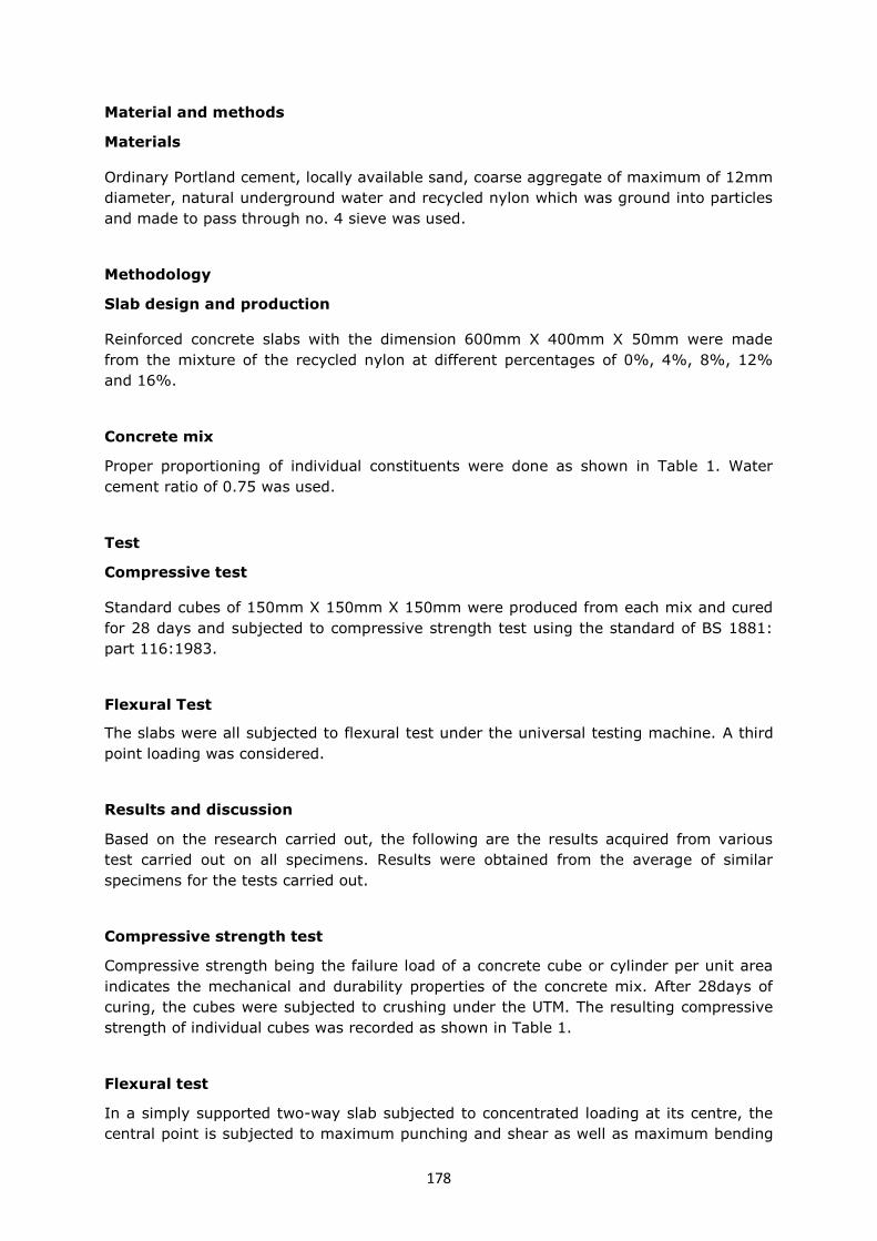
178
Material and methods
Materials
Ordinary Portland cement, locally available sand, coarse aggregate of maximum of 12mm
diameter, natural underground water and recycled nylon which was ground into particles
and made to pass through no. 4 sieve was used.
Methodology
Slab design and production
Reinforced concrete slabs with the dimension 600mm X 400mm X 50mm were made
from the mixture of the recycled nylon at different percentages of 0%, 4%, 8%, 12%
and 16%.
Concrete mix
Proper proportioning of individual constituents were done as shown in Table 1. Water
cement ratio of 0.75 was used.
Test
Compressive test
Standard cubes of 150mm X 150mm X 150mm were produced from each mix and cured
for 28 days and subjected to compressive strength test using the standard of BS 1881:
part 116:1983.
Flexural Test
The slabs were all subjected to flexural test under the universal testing machine. A third
point loading was considered.
Results and discussion
Based on the research carried out, the following are the results acquired from various
test carried out on all specimens. Results were obtained from the average of similar
specimens for the tests carried out.
Compressive strength test
Compressive strength being the failure load of a concrete cube or cylinder per unit area
indicates the mechanical and durability properties of the concrete mix. After 28days of
curing, the cubes were subjected to crushing under the UTM. The resulting compressive
strength of individual cubes was recorded as shown in Table 1.
Flexural test
In a simply supported two-way slab subjected to concentrated loading at its centre, the
central point is subjected to maximum punching and shear as well as maximum bending

179
moment. Failure may therefore be due to combination of flexure and shear with the
former generally dominating. The largest flexural strains therefore occur at the point of
load application, consequently, cracking initiates at the soffit of the region, from where
the cracks then spread rapidly to the edges of the slab with increasing load to collapse
[3]. The measurement of the resistance to bending of the slabs was carried out following
the third point loading.
This test indicates that the bending strength of the slab reduced at a lower rate from the
beginning but after some time, the bending was accompanied with great deflections
corresponding to low forces.
The equation
was used in calculating the flexural strength and recorded as
shown in Table 1.
Deflection and cracks
Crack width was minimal and gradually increases but insignificant values at the early
stage of aggregate replacement and with further increase in waste material, cracks
occurring became significant (Figure 2).
Results revealed that, at 4% and 8% recycled nylon in concrete mix revealed close
proximity in strength to the conventional concrete at 0% under similar exposure and
conditions from both compressive strength and flexural strengths. The water demand for
proper mix of the concrete increases as the percentage of the recycled waste increases.
The weight of the cubes and slabs decreases gradually with increase in recycled waste in
the mix. There was no very large difference between concrete slab and cube without
replacement and slabs and cubes with replacement of 4% and 8%. With large increase in
parentage of recycled waste, there was drastic reduction in strength of concrete.
Conclusion
With the overwhelming increase in nylon waste around, and the significant response of
the concrete with 4% to 8% replaced fine aggregate, the use of such concrete should be
adopted in construction to aid waste management around the world.
However, the water demand was discovered to increase as the percentage of the
recycled waste increases. This certainly continues to reduce the workability of the
concrete. The work concluded that at 4%, the recycled waste can be used to partially
replace fine aggregate in reinforced concrete slabs with no critical loading conditions.

180
Figures and tables
Figure 1: Flexural strength test
Figure 2: Load deflection response of specimens.
0
10
20
30
40
50
60
0 2 4 6 8
load
(K
N)
deflection (mm)
0%
4%
8%
12%
16%

181
Table 1: Compressive strength and Flexural strength at age 28days.
% of nylon waste Average compressive
strength
N/mm2
Average flexural
strength
N/mm2
0 19.07 38.40
4 16.28 32.00
8 15.74 33.60
12 12.59 32.00
14 9.62 38.40
References
[1] Job Thomas, “Utilization of quarry powder as a substitute for the river sand in
concrete”, Journal of Structural Engineering., vol.32, no.5, pp. 401-407, December
2005.
[2] Sachin B. K, Amol J. M, Vijayshree A. A 2012, “Strength of Concrete Containing
Different Types Of Fine Aggregate” International Journal Of Scientific & Engineering
Research Volume 3, Issue 9, September-2012 1 ISSN 2229-5518.
[3] Kankam C.K, Odum-Ewuakye B. 2006. Flexural behaviour of babadua reinforced
one-way slabs subjected to third-point loading construction of building materials 20
(2006) 279-285.

182

183
USE OF SUGARCANE BAGASSE FIBRE AS A SOIL REINFORCEMENT
MATERIAL
Vincent Oderah
Department of Civil Engineering, University of Cape Town, Cape Town, South Africa
Brief author biography
Vincent Oderah obtained a BSc (Eng) in Environmental and Biosystems engineering at
the University of Nairobi and is currently pursuing his MSc (Eng) in Geotechnical
Engineering at the University of Cape Town. His research focus is on sustainable re-use
of waste materials and natural fibres as reinforcement inclusions in soil aimed at
establishing their viability in ground improvement schemes. He is a member of the
geotechnical research group at the University of Cape Town.
Introduction
Sugarcane is the most lignocellulosic crop produced in the tropical countries. 30% of the
total sugarcane produced is sugarcane bagasse [1]. South Africa for instance, produces
about 22 million tonnes of sugarcane annually amounting to 7.5 million tonnes of
sugarcane bagasse [2]. The bagasse produced (which is considered an industrial waste in
the sugar industries) presents handling problems. It ferments and decays and at the
same time is susceptible to combustion in stockpiles. To solve these problems, projects
such as cogeneration, paper, furfural, animal feed production have been explored as an
alternative solution [2, 3]. At any rate, the disposal of bagasse is still a major problem in
sugar factories especially in countries that are yet to embrace these diversification
projects. This condition is aggravated by the urge to reduce the waste material destined
to landfills, landfills which some countries do not have.
A study program was therefore initiated at the University of Cape Town to investigate the
possible use of sugarcane bagasse fibre as a reinforcement material. This was in a bid of
reducing the menace posed by handling sugarcane bagasse by using the fibres in
improving the shear strength of soils. Furthermore, it was envisaged that the structural
components of bagasse such as lignin, cellulose, and hemicellulose would make it an
ideal reinforcing material [4]. The study focussed mostly on the effect of bagasse
volumetric concentrations.
Methodology
A sandy soil was reinforced with sugarcane bagasse of different volumetric concentration
and tested in a fully automated large direct shear apparatus of 305x305mm. The extent
of strength and stiffness response due to the inclusion of bagasse was compared with the
unreinforced soil strength. In the investigation, both pithed and de-pithed bagasse were
used in reinforcing at a concentration of 0.3-1.7% of dry unit weight. 50, 100, and
200kPa normal loads were applied at a shear rate of 1.2mm/min corresponding to the
recommendation from previous studies [5-8]. A maximum of 60mm horizontal

184
displacement was achieved for both normal pressures and the corresponding peak shear
strengths used in calculating the cohesion and angle of internal friction as shown in figure
2.
Results
The results showed an increase in both strength and stiffness of the reinforced sandy soil
with increasing concentration of bagasse, figure 1 and 2. The strength improved non-
linearly up to an asymptotic upper value of 1% concentration beyond which further
addition of fibre reduced the strength as shown in figure 3. The increase was more
pronounced in the de-pithed bagasse compared to millrun due to increased surface
friction between the fibres and soil, figure 3. This was attributed to the increased surface
friction between the fibres and soil [9-11]. In both millrun and pith, the cohesion was
much increased compared to angle of internal friction. A factor attributed to the
cementitious nature of the residual sugars existing in pithed bagasse which binds
together the soil particle and consequently improving cohesion and angle of internal
friction slightly [5].
Conclusions
Using sugarcane bagasse as a reinforcing element is feasible. Including these materials
randomly in the soil improves the soil’s shear strength.
This gives an indication that using sugarcane bagasse as a reinforcing material could
provide an alternative way of using bagasse, and replace part of the soil stabilization
materials like cement, lime and bitumen used in improving the engineering properties of
soils.
For the sugarcane bagasse reinforcement to be effective all the residual sugars must be
screened out.
This notwithstanding, pithed bagasse in as much as it contain a higher percentage of
organic matter could be used as an additive in cementitious applications. The mechanism
and the results thereof were however beyond the scope of the investigation.

185
Figures and tables
Figure 1: Showing the increase in strength with increasing percentage of (a) fibre (b)
Mill-run (c) Pith at 200kPa normal stress

186
Figure 2: Linear shear envelope, showing upper asymptotic value of 1% fibre
concentration.
Figure 3: Effect of bagasse concentration of shear strength.
References
[1] National Agricultural Marketing Council. Document 5: Investigation and Evaluation
of Alternative Uses and Products from Sugarcane: A Cost Benefit and Macro-
Economic Impact Analysis. 2013.Web. 5 June 2014.
[2] United Nations Data. Bagasse Production in South Africa. 2010. Web. June 5, 2014
[3] Mwasiswebe, Denny. Production of Activated Carbon from South African Sugarcane
Bagasse. (M.Sc.Eng.) Chemical Engineering -University of KwaZulu-Natal, 2005.
[4] Walford, S. Sugarcane bagasse: How easy is it to measure its constituents?
Proceedings of the South African Sugar Technologists Association, 2008, vol. 81,
pp. 266-273.
R² = 0.9998
R² = 0.9988
R² = 0.9998
R² = 0.9979
0
50
100
150
200
250
300
350
400
50 100 150 200 250 300 350 400
Sh
ear S
tress (
kP
a)
Normal Stress (kPa)
0%
0.30%
0.70%
1%
1.40%
1.70%
30
32
34
36
38
40
42
0.0% 0.5% 1.0% 1.5% 2.0%
Sh
ear S
tren
gth
(kP
a)
Concentration (%)
Fibre
Millrun
Pith

187
[5] Loh, Y.R., Sujan, D., Rahman, M.E. & Das, C.A. Sugarcane bagasse -The future
composite material: A literature review. Resources, Conservation and Recycling.
75(0): 2013 14-22.
[6] Hejazi, S.M., Sheikhzadeh, M., Abtahi, S.M. & Zadhoush, A. A Simple Review of
Soil Reinforcement by using Natural and Synthetic Fibers." Construction and
Building Materials 30 (2012): 100-16.
[7] Anagnostopoulos, C. a. et al. Shear Strength of Sands Reinforced with
Polypropylene Fibers. Geotechnical and Geological Engineering, 2013, 31(2),
pp.401–423.
[8] Gray, D.H. & Ohashi, H. Mechanics of Fiber Reinforcement in Sand. Journal of
Geotechnical Engineering, 109(3), 1983, pp.335–353.
[9] Sadek, S. et al., 2010. Shear Strength of Fiber-Reinforced Sands. , (March),
pp.490–499.
[10] Shao, W. et al. Experimental Investigation of Mechanical Properties of Sands
Reinforced with Discrete Randomly Distributed Fiber. Geotechnical and Geological
Engineering, 32(4), 2014, pp.901–910.
[11] Yetimoglu, T. & Salbas, O. A study on shear strength of sands reinforced with
randomly distributed discrete fibers. Geotextiles and Geomembranes, 21(2), 2003,
pp.103–110.

188

189
EARTHEN PANELS – QUALITY CONTROL FOR AN INDUSTRIALLY
PREFABRICATED BUILDING COMPONENT MADE OF NATURAL RAW
MATERIALS
Astrid Paul
Federal Institute for Materials Research and Testing, Berlin, Germany
Patrick Fontana
Federal Institute for Materials Research and Testing, Berlin, Germany
Christof Ziegert
Federal Institute for Materials Research and Testing, Berlin, Germany
Brief author biography
Astrid Paul graduated in architecture at the University of Stuttgart and is a skilled
craftswoman for earthen building techniques. She is presently working at the BAM
Federal Institute for Materials Research and Testing in Berlin, Germany, in the division
“Building Materials” where she is focussing on the investigation of earthen materials.
Introduction
In the past few years, the share of earthen building materials used in constructions in
Central Europe has increased. That is due to growing acknowledgement of its qualities
regarding balancing of humidity, absorption of odours and acoustical insulation.
To regulate these (mostly indoor) uses, the German Institute for Standardization (DIN)
has published norms for adobe [1], earth mortar for masonry [2] and earth plaster [3].
In addition to these traditional building materials, earthen panels have been developed.
As an ecological alternative to gypsum plaster boards, they combine climatic advantages
of traditional materials with economic advantages of industrial processing, i.e.
prefabrication and drywall techniques. Earthen panels are a composite layered material,
comparable to Textile Reinforced Concrete (TRC). Most products contain an inner layer of
reed tubes which improve the tensile strength and reduce the weight. Often, one or both
surfaces are reinforced with a fibrous net to prevent cracks in the plastering that is
usually applied on top. Additives range from straw to expanded clay. Special panels
contain waxes that improve their heat storage capacity or water pipes to allow the usage
as flat heating and cooling systems.
Test programme
The product development, however, is still a work in progress. Several cases of cracks
and other damages have shown a need for quality control and a lack of knowledge and

190
experience. Therefore, the BAM Federal Institute for Materials Research and Testing and
the German producer Conluto have launched the project “Standard Board” supported by
the German Association for Building with Earth (DVL). Its aim is to create a basis for
another DIN standard that defines requirements of earthen panels. Special panels as
mentioned above are going to be subject of this new standard as well, but without
consideration of their special qualities. The test programme has been designed following
the testing of comparable materials as gypsum plaster boards, wooden panels etc. It is
designed to ensure that panels meet with the requirements related to the limit state of
usability as defined in DIN 1055 [4]:
Distortions and shifts that disturb the effective usage, damage not load-bearing
parts or change the appearance
Vibrations that cause discomfort, damage the construction or reduce its usability
Damages (including cracks) that prospectively will impair the operability, durance or
appearance of the construction
Visible damages caused by material fatigue or other time-dependent effects
Currently the programme includes tests to estimate:
Dimensional accuracy and stability
Bending tensile strength
Resistance to horizontal loads
Resistance to impacts caused by soft or hard bodies
Tensile surface strength and/or surface hardness
Length variation caused by humidity changes, absorption of water vapour
Reaction to contact with water
The latter is going to be one of the main issues. Earthen panels with certain humidity
that dry faster on one surface than on the other one may cup during the drying process,
thus causing cracks. In analogy to gypsum plaster boards it will be unavoidable to define
a maximum for shrinkage strain in accordance to the environmental temperature and a
maximum distance for joint gaps.
Preliminary Results
Dimensional accuracy
The accuracy of length, width and angular dimensions is very high, with a maximum
variance of 0.3 mm from the nominal size of 62.5 cm. Nevertheless, large divergences of
thickness have been measured. Measurements have been taken on every edge of 5
panels and led to differences form -2 mm to +5 mm from the nominal size (See Fig. 1).
In this case, high differences of adjacent panels fixed to a substructure would add up to
more than 7 mm. Thus, the maximum plaster thickness of 4 or 5 mm recommended by
most manufacturers could not be abided.

191
The requirement of a maximum plaster height is explained by the necessity of controlling
the quantity of water that enters from the fresh plaster into the panel and is therefore an
important matter in terms of quality control. That is why the reason for this high
variation and a solution are urgent issues. The reason may be found in an inappropriate
production process, which will be investigated in a subsequent phase of the project.
Should it not be possible to ensure a maximum variety of 2-3 mm, either different
instructions concerning type and thickness of earth plaster applied on the surfaces,
mechanical equalization techniques or a combination of both must be introduced.
Tensile surface strength
To determine the tensile strength of the surface, steel cylinders with a diameter of 50
mm were glued with an epoxy resin on the earthen panels and then pulled off. The
results cover a very large range from approx. 150 to 300 N/mm². The scattered results
are probably due to the inhomogeneity of the material and the large mesh size of the
reinforcement net or the position of the reinforcement net in the cross section of the
panels.
The test results however have led to another observation. Areas with average ultimate
loads larger or smaller than 200 N are located on different areas of the panels. The
reason of this asymmetry may lie in the fabrication process and will be further
investigated.
Humidity-induced length variation
Cracks in a plaster, caused by humidity-induced deformation of panels are the most
frequent damage claimed by customers. The large vapour adsorption capacity of earthen
materials is on one hand one of its most advertised features, but on the other hand leads
to the mentioned damage as the deformation of the panels is directly proportional to the
vapour adsorption.
To investigate this phenomenon, samples of 160 mm x 40 mm have been suspended to a
climate of changing relative humidity. With a start value of 23 °C and 50% RH, the
relative humidity has been increased to 80% and then decreased to 30%, each step
starting after mass equilibrium had been reached.
First results show an expansion up to approx. 0.3 mm/m, larger values are to be
expected because of the quality range of available products. This means that panels with
a length of 1.25 m can show plaster cracks in the joints with a width of 0.3 mm which
are clearly visible to the human eye.
It is possible that the application of reinforced plasters reduces that effect. Still, there is
need for additional, more reliable solutions. The proceeding of the project may lead to
more satisfying approaches.
Conclusions
The introduction of the new DIN standard will bring several advantages not only to
planers and manufacturers but also to craftspeople. While nowadays the earth building
industry enjoys many liberties but lacks quality control, regimentation will establish a
compulsory minimum standard and thus ensure quality and competitiveness. This

192
development - as it is attended with additional costs for quality surveillance tests - is not
welcome to all who are concerned but presents the only opportunity to establish earthen
building materials as a serious alternative to conventional products on a highly regulated
market. But presently there is a need for further, more intense and detailed
investigations. This project offers the opportunity not only to meet with the aims of
reaching the comparability between earth panels and other panels but also to extend the
understanding of the panels system as well.
Figures and tables
Figure 1: Thickness variation in contrast to nominal size and maximum tolerance defined
by producer.
References
[1] DIN 18945: Earth blocks – Terms and definitions, requirements, test methods:
2013.
[2] DIN 18946: Earth masonry mortar - Terms and definitions, requirements, test
methods: 2013.
[3] DIN 18947: Earth plasters – Terms and definitions, requirements, test methods:
2013.
[4] DIN 1055-100: Actions on structures. Part 100: Basis of design, safety concept and
design rules: 2001, p. 26.

Organised by:
Financial support from:
Scientific support from: