PROCEDURES FOR SETTING A CORS MONUMENT - … · PROCEDURES FOR SETTING A CORS MONUMENT This...
31
PROCEDURES FOR SETTING A CORS MONUMENT This document was prepared to assist in constructing a CORS monument according to the recommendations developed by the National Geodetic Survey (NGS). The instructions and drawings depict the establishment of a monument meeting all of the recommended conditions. Adaptation of the recommendations will certainly occur. Contact NGS for assistance and instruction in situations differing from those described herein. Once a suitable site has been selected, preparations for the construction and setting of the CORS monument can begin. First, acquire and gather together a variety of materials that will be needed to build the monument. Second, locate and make scheduling arrangements with companies to machine components of the antenna mount, check for underground cables at the site, auger the lower pier hole and deliver the concrete. Third, assemble monument components and setting aids prior to pouring the concrete. Materials Materials needed for Antenna Mount: 1 - 6-1/2 inch diameter by 1 inch thick Delrin plate 3 - 1 inch diameter by 12 inches long Delrin rods 1 - Off the shelf tribrach adapter 3 - Stainless steel bolts 5/16 in. x 1-1/2 in. x 18 tribrach attachment studs Make arrangements for machining work of Delrin materials. A detailed description of the Antenna Mount construction follows. Materials needed for C-Bar Reinforcement Assembly: 4 - 5/8 inch diameter by 8 ft. long C-Bar rods 1 - 5-1/2 inch inside diameter by 1-2 feet long piece of PVC pipe 32 - Plastic Cable Ties to construct C-Bar reinforcement assembly A detailed description of the C-Bar assembly construction follows. Materials and tools needed for setting monument: 1 - Assembled Antenna Mount 1 - Assembled C-Bar Reinforcement Assembly 1 - 12 inch diameter by 5 foot tall Sonotube form 8 - 8 foot long 2 x 4 lumber 6 - 1-2 ft long 1 inch x 1 inch wooden stakes 1 - Box of 3 inch dry wall screws 1 - Box of 1 inch dry wall screws Saws, hammer, cordless drill, trowels, one or two 3 ft. step ladders, shovels and hoe. Materials for finishing the monument after curing :
Transcript of PROCEDURES FOR SETTING A CORS MONUMENT - … · PROCEDURES FOR SETTING A CORS MONUMENT This...

PROCEDURES FOR SETTING A CORS MONUMENT
This document was prepared to assist in constructing a CORS monument according to therecommendations developed by the National Geodetic Survey (NGS). The instructions anddrawings depict the establishment of a monument meeting all of the recommended conditions. Adaptation of the recommendations will certainly occur. Contact NGS for assistance andinstruction in situations differing from those described herein.
Once a suitable site has been selected, preparations for the construction and setting of the CORSmonument can begin. First, acquire and gather together a variety of materials that will be neededto build the monument. Second, locate and make scheduling arrangements with companies tomachine components of the antenna mount, check for underground cables at the site, auger thelower pier hole and deliver the concrete. Third, assemble monument components and settingaids prior to pouring the concrete.
Materials
Materials needed for Antenna Mount:
1 - 6-1/2 inch diameter by 1 inch thick Delrin plate3 - 1 inch diameter by 12 inches long Delrin rods1 - Off the shelf tribrach adapter3 - Stainless steel bolts 5/16 in. x 1-1/2 in. x 18 tribrach attachment studsMake arrangements for machining work of Delrin materials.A detailed description of the Antenna Mount construction follows.
Materials needed for C-Bar Reinforcement Assembly:
4 - 5/8 inch diameter by 8 ft. long C-Bar rods1 - 5-1/2 inch inside diameter by 1-2 feet long piece of PVC pipe
32 - Plastic Cable Ties to construct C-Bar reinforcement assemblyA detailed description of the C-Bar assembly construction follows.
Materials and tools needed for setting monument:
1 - Assembled Antenna Mount1 - Assembled C-Bar Reinforcement Assembly1 - 12 inch diameter by 5 foot tall Sonotube form
8 - 8 foot long 2 x 4 lumber 6 - 1-2 ft long 1 inch x 1 inch wooden stakes 1 - Box of 3 inch dry wall screws 1 - Box of 1 inch dry wall screws
Saws, hammer, cordless drill, trowels, one or two 3 ft. step ladders, shovels andhoe.
Materials for finishing the monument after curing :

Hydraulic cement to seal joint between upper and lower piers.Concrete filler cement to fill any holes on surface of upper pier White concrete sealer to paint monument.
Scheduling Services
Take the Antenna Mount materials and construction instructions to a machine shop. Be surethey can do the work and deliver the mount prior to setting the monument.
Contact a company, such as, “Miss Utilities”, to check the site for the location of undergroundcables, phone lines and water pipes prior to auguring hole.
Although it may be possible to auger the hole and pour the concrete in the same day, it isprobably better to schedule the auguring on one day and pouring the concrete the next day orlater. Contact a company to auger monument hole and schedule time of work. Types ofcompanies that may have an 18 to 24 inch auger are electric power companies, state departmentsof transportation, well drillers, and highway engineering construction companies.
Contact a concrete delivery company and order cement type Portland A3, air entrained, with anaggregate size of 3/4 to 1½ inches and schedule delivery. Explain to the concrete company thatyour are setting a stepped tiered pier and want to pour the entire upper and lower piers in onepouring. The slump of the concrete should be for a dry mix so that the concrete will not leak outfrom under the upper pier form when poured. Be sure to carefully compute or have concretecompany compute the amount of concrete you will need. Get an extra ½ - 1 yard to be sureyou will have enough to finish the monument in one pouring.
Make arrangements to pickup, from an equipment rental company, a concrete vibrator to settleconcrete when pouring. Be sure that this item will be available at the same time as the concretedelivery.

CONSTRUCTION OF THE RECOMMENDED CORS ANTENNA MOUNT
Recommended Antenna Mount
A custom-made antenna mount consisting of a tribrach adapter mounted on a Delrin base. Theantenna mount base, which must be custom-machined, consists of three notched Delrin legs(recommended dimensions are 1 in (2.54 cm) diameter and 12 in (0.3 m) long) that are threadedinto the underside of a circular Delrin platform (recommended dimensions are 6 in (0.15 m)diameter and 1 in (2.54 cm) thick). To allow for the antenna attachment, and its orientation tonorth, a standard, commercially-available tribrach adapter is attached to the Delrin platform. Toattach the tribrach adapter to the platform, the standard tribrach studs (feet) are replaced withthreaded studs that are screwed into the top of the Delrin platform. The tribrach adapter issecured to the studs with set screws. A locking screw secures the tribrach adapter plug once theantenna is oriented to true north.
Construction of the recommended antenna mount should be easily accomplished by anyexperienced machinist. The following drawings were made to identify the various components ofthe antenna mount and to describe the measurements, modifications and machining made toeach component before assembly.
The antenna mount consists of four major components: tribrach adapter, tribrach adaptermounting studs, Delrin plate or platform, and the Delrin legs.
1. Tribrach Adapter
The tribrach adapter component is a standard adapter used in surveying to attach targetsand GPS antennas to the top of tripods. It is precision made to clamp into a standardtribrach which is used for centering and leveling the target or antenna. The location of thefeet or studs to which the adapter clamps into the tribrach have been standardized toallow the use of the adapter with tribrachs of various manufacturers. Construction of theantenna mount requires the precise location of three mounting studs in the top of theDelrin plate in order to attach the tribrach adapter. No modification, other than theremoval of the standard feet, of the tribrach adapter is required. If the studs a locatedcorrectly, the holes in the bottom of the adapter should fit snugly over them. The setscrews that held the original feet can now be tightened to secure the adapter to the studs.
2. Tribrach Adapter Mounting Studs
The tribrach adapter mounting studs consist of modified stainless steel bolts that arethreaded into tapped holes in the top of the Delrin plate. The bolts required are 1-1/2 inchlong by 5/16 inch diameter with 18 threads per inch. Modifications required are theremoval of the bolt heads, machining a notch for the set screw, and cutting a screw driverslot in the top. The studs must be precisely positioned on the top side of the Delrin plateto exactly fit into the holes in the bottom of the tribrach adapter.

3. Delrin Plate or Platform
The Delrin plate is a 6 inch diameter by 1 inch thick plate or disk used to provide supportfor and an attachment point for the tribrach adapter and connect solidly to the top of theupper concrete pier. The Delrin comes in a variety of shapes, sizes and thickness. TheDelrin used for the support plate is constructed from a piece of flat 1-inch thick materialrough-cut into a disk about 6-1/2 inches in diameter. The initial modification is to smooththe rough-cut edge in a lathe to about a 6-inch diameter. This dimension does not need tobe an exact 6 inches, but should be clean enough to allow measurement of the locationpoints for the tribrach adapter mounting studs on the top of the plate. A good machinistshould know how best to do these measurements. Location of the mounting points of thelegs on the bottom of the plate is not as critical as the studs, but they should be located ata distance from the edge of the plate sufficient to obtain the greatest strength of thethreaded joint. Although the drawings recommend using 3/4 in. x 10 threads to attach thelegs, ½ in. x 13 in. could also be used.
4. Delrin Legs
The three antenna mount legs provide the attachment points of the mount to the top ofthe upper concrete pier. They are constructed from 1-inch diameter by 1-foot long Delrinrods. The top of the legs are turned to a diameter that allows 3/4 inch diameter by 10threads per inch threads to be die-cut to a length of a 7/8 inch. Complementary holes aredrilled and tapped on the bottom of the Delrin plate. At the other end of each leg, a 1-inch tapered point is turned. The points make it easier to push the antenna mount into thewet concrete. Finally, three 1-inch notches are cut to a depth of 1/8 inch or a diameter of3/4 inch. The notches provide places for the concrete to grip and hold the antenna mountin place.
Availability of Materials
Availability of the materials for the antenna mount should be quite good. The tribrach adapter isan off-the-shelf surveying item and is sold by about all surveying supply companies and originalmanufacturers. The stainless steel mounting stud bolts should be readily available from a varietyof supply houses. The Delrin acetal resin material used for the antenna mounting plate and legscan be obtained from any good plastic products company and comes in a variety of shapes andsizes.
Construction of the Antenna Mount
Order all of the materials needed for the antenna mount. For one antenna mount you shouldhave the following:
1 - Tribrach Adapter1 - Delrin plate rough-cut to a diameter 6-1/2 inches3 - Stainless steel bolts, 1-1/2 in. x 5/16 in. x 183 - Delrin rods, 5/8 inch diameter x 12 inches long

Take all these materials and this document to a machine shop. Hopefully, the machinist will beable to tell you if he can do the work and give you a cost estimate for the construction based onthis information.
Remember, the goals of the recommended antenna mount design were to minimize the amountof metal near the antenna and fix the antenna to the upper pier without creating any resonancecavities beneath the antenna.
Antenna Mount Drawings
The first drawing is an overview of the antenna mount depicting each of the components, therequired modifications to them, and an exploded view of the antenna mount showing eachcomponent. It is followed by a one page drawing showing the Tribrach Adapter in great detail. Next is a one page drawing showing construction of the tribrach attachment studs. The next twopages (Delrin Plate - Part 1 and Delrin Plate - Part 2) depict the modifications to the Delrin plate. The last drawing shows the modifications to the Delrin rods needed to create the antenna mountlegs.


CONSTRUCTION OF THE C-BAR REINFORCEMENT ASSEMBLY
Materials required for one C-Bar reinforcement assembly:
4 - 5/8 inch diameter by 8 foot long C-Bar rods 4 - 5-1/2 inch inside diameter by ½ inch width PVC rings32 - Plastic Cable Ties (medium duty 3/8 inch wide and 14-1/2 inches long)
WARNING: ALWAYS WEAR GLOVES WHEN HANDLING C-BAR RODS. FIBERSWILL PENETRATE SKIN!
Construction of the C-Bar reinforcement assembly is very straight forward. The only componentrequiring some prior work is the PVC rings. If a power hack saw is available, it will make shortwork of this. Take about a two foot long piece of 5-1/2 inch inside diameter PVC pipe and fromone end make marks at ½ inch intervals. Place the PVC in the power hack saw and at each markcut a half inch width ring. You will need four rings for each reinforcement assembly. Thefollowing drawing “COMPONENTS AND CONSTRUCTION OF C-BAR REINFORCEMENTASSEMBLY” depicts and describes the construction of the reinforcement assembly.
NOTE: If CORS monument setting requires that a shallow lower pier is set due to hittingbedrock, it may be necessary to shorten the length of the C-Bar rods. The C-Bar rods can be cut,but it is necessary to SEAL the ENDS where they are cut. If this is the case, order some sealingmaterial from the C-Bar company. It is called EPDM Rubber Spray Coating.

PREPARING SONOTUBE FORM AND SUPPORT BRACES
NOTE: The step numbers stated in the following text refer to the step numbers depicted in thedrawings interspersed in the text.
Materials List1 - 12 inch diameter by 5 foot Sonotube form1 - Short piece of Sonotube, a foot or less tall10 - 8 foot two by fours (2x4)6 - 1-1/2 foot by 2x2 or 1x2 inch stakesBox - 3-1/2 inch dry wall screwsBox - 1 inch dry wall screws
Tools1 - Cordless Drill1 - Hand saw or table saw 1 - Tape measure1 - Square1 - Protractor
The following Steps, 1 - 5, can be done prior to going to the monument site.
STEP 1 - Measure and cut Sonotube form to a length of 5 ft. keeping the ends as square aspossible. Sonotube usually comes in 12 foot lengths. If this is the case, cut it into two 6 footpieces, then cut each piece to the needed 5 foot length. Use a carpenters square or a tape measureto mark where the cut off line will be on the form. The will keep the ends square. Keep one ofthe short pieces cut off. This will be used when pouring the concrete to make a indentation in thewet cement for positioning the Sonotube form for the upper pier.
STEP 2 - Cut 6 pieces of 2x4 to a length of about 30 inches. On one end of each of the 30 inchpieces, cut the end to an angle of 60 degrees along the narrow dimension.
STEP 3 - Set the Sonotube upright on a flat surface. Place 3 of the 30 in. pieces around theSonotube form with the narrow width down. Butt the angled ends against the inside of theadjacent pieces. Adjust the pieces so that the inside surface touch the Sonotube and the angledends are still in contact with its adjacent piece. The none angled ends of the pieces should projectbeyond the point where the angled end makes contact.
Starting at one of the intersections where the angled end meets the inside of it adjacent piece,drill two pilot holes from the outside piece into the adjacent angled end and then connect usingtwo 3-1/2 inch drywall screws. Move to the next intersection and while keeping the pieces snugagainst the side of the Sonotube form, again drill two pilot holes and secure the pieces with two3-1/2 in. drywall screws. Do the same for the last intersection, while holding the pieces tightagainst the Sonotube. All 3 of the pieces should now be connected and snug against theSonotube.

If the CORS monument is being set on flat terrain, then move the assemble bracket up theSonotube so that about an inch of the Sonotube projects below the bottom edge of the threesides of the bracket.
Without moving the bracket, lay the Sonotube on its side so that access can be made to the insideof the tube. From inside the Sonotube, at the point where the inside of the bracket pieces touchthe Sonotube, secure the Sonotube to each piece using one or two of the 1 inch drywall screws. This will be the upper support bracket.
STEP 4 - Stand the Sonotube upright again with the just attached bracket at the top and repeatthe assembly described in Step 3 above for the bracket at the bottom. This will be the lowersupport bracket.
STEP 5 - Cut 3 pieces of 2x4 to a length of about two feet. These pieces will be called the loweradjusting brackets. With the Sonotube sitting in an upright position, overlap the end of one ofthe adjusting brackets on the outside of and about 4 or 5 inches from the extended end of one ofthe corners of the lower support bracket. At about the middle of the overlap section, drill a pilothole and drive a single 3-1/2 in. drywall screw just tight enough to allow the adjusting bracket topivot. Do the same for the other 2 corners of the lower support bracket. The adjusting bracketsprovide the means to plumb and raise or lower the sonotube form at the CORS monument site.


AUGURING THE HOLE AND POURING THE CONCRETE
The following Steps, 6 - 29, are done at the monument setting site.
STEP 6 - Auger the hole for the lower pier. Measure the depth of the hole as the diggingprogresses. Don’t drill it more than 10 feet or more concrete will be required. After the hole isdone, remeasure its depth and diameter and compute the volume to determine if more concretewill be needed. If so, advise the concrete company.
STEP 7 - After the hole is augured, clear away the dirt left around It. Be careful not to let anydirt fall back into the hole.
STEP 8 - Begin pouring concrete. Every two feet of pour, insert the vibrator to settle theconcrete and remove air bubbles. Don’t leave the vibrator in the concrete very long or it willcause the aggregate to settle and the water to separate (15 to 30 seconds at time).
STEP 9 - Continue pouring and vibrating. Measure the level of the concrete below the surface ofthe ground. When the height below the ground reaches 4 feet or a little more, stop pouring.Place the C-Bar Reinforcement Rod Assembly into the hole and center it as close as possible.Measure the height of the top of the C-bar Assembly above the ground. It should be 4 feet orless. Anywhere from 3 feet 5 inches to 3 feet 10 inches will be good. If necessary, move theassembly up or down in the concrete. Be sure to keep it centered. Use two people to hold theassembly.
STEP 10 - Continue pouring and vibrating the concrete. Use a 2 to 3 foot carpenters level tocheck the plumb of the C-Bar Assembly. It is important to keep the assembly as plumb aspossible so it will stay centered in the upper pier when it is poured. Do not allow the concrete topush the assemble sideways.
STEP 11 - Continue pouring and vibrating the concrete and keeping the C-Bar Assembly inposition until the concrete is at the surface of the ground. Check the plumb and the height abovethe ground of the C-Bar Assembly. The assembly should be still centered, plumb and 3 ½ to 4feet above the ground.
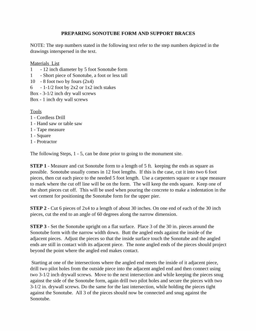
STEP 12 - Place the short piece of 12 inch Sonotube over the C-Bar Assembly and gently set iton the top of the wet concrete. Center the C-Bar Assembly in the center of the Sonotube circleby moving the Sonotube around. Once centered, press the Sonotube into the wet cement enoughto leave a visible indentation. Remove the short piece of Sonotube.
STEP 13 - Carefully lift the 5 foot Sonotube form with brackets up and over the C-BarAssembly. Set it down so that the bottom perimeter of the form sets into the indentation made inStep 12 and the bottom support bracket and adjusting brackets support it by sitting on the groundsurface. Using a step ladder, look down into the form to determine if the C-Bar Assembly inreasonably centered.


STEP 14 - At about the middle of each of the adjusting brackets, drive a support stake solidlyinto the ground.
STEP 15 - Use one or two 2-3 foot carpenters levels to plumb the Sonotube form. Use a stepladder to look down into the form and see that the C-Bar Assembly is still centered in the form.Adjust the form if necessary. The bottom of the form should be just touching or slightlyimbedded into the wet concrete of the base pier. If the form is at the correct height, plumb andthe C-Bar centered, drive a 3 ½ inch drywall screw near the one where the adjusting bracketpivots to fix the bracket in place. Do this at all three adjusting brackets. Check the plumb andcentering again. If all is ok, then drive two 3 ½ inch drywall screws through each of the adjustingbrackets and into each of the support stakes. The form should now stay securely in place.
STEP 16 - Place the end of an 8 foot 2x4 at each of the extended ends of the upper supportbracket and attach by driving a 3 ½ inch drywall screw. The other ends of the 8 foot 2x4s can justsit on the ground. Near the ends of each of the 8 foot 2x4s touching the ground drive a supportstake.
STEP 17 - Check the plumb and centering of the Sonotube form again. If all is good, drive asecond 3 ½ inch drywall screw near the ones in the extended ends of the upper support bracket. Next, drive two 3 ½ inch drywall screws through the 8 foot 2x4s and into the just driven supportstakes. The Sonotube form should now be plumb, fixed very rigidly in place and ready for therest of the concrete to be poured.
STEP 18 - To pour the concrete into the Sonotube form, get a couple of short step ladders orboxes high enough to allow viewing down into the form. Slowly shovel or hoe the wet concreteinto the form. Make sure the C-Bar Reinforcement Assembly stays centered. The concrete maytend to push it to one side. After pouring a foot or so, tamp the concrete with a stick to settle it inaround the C-Bar assembly. !!! WARNING !!! BY NO MEANS USE THE VIBRATOR TOSETTLE THE CONCRETE IN THE SONOTUBE FORM AS IT COULD POSSIBLEEXPLODE THE FORM.
STEP 19 - Continue pouring and tamping the concrete and keeping the C-Bar assemblycentered.
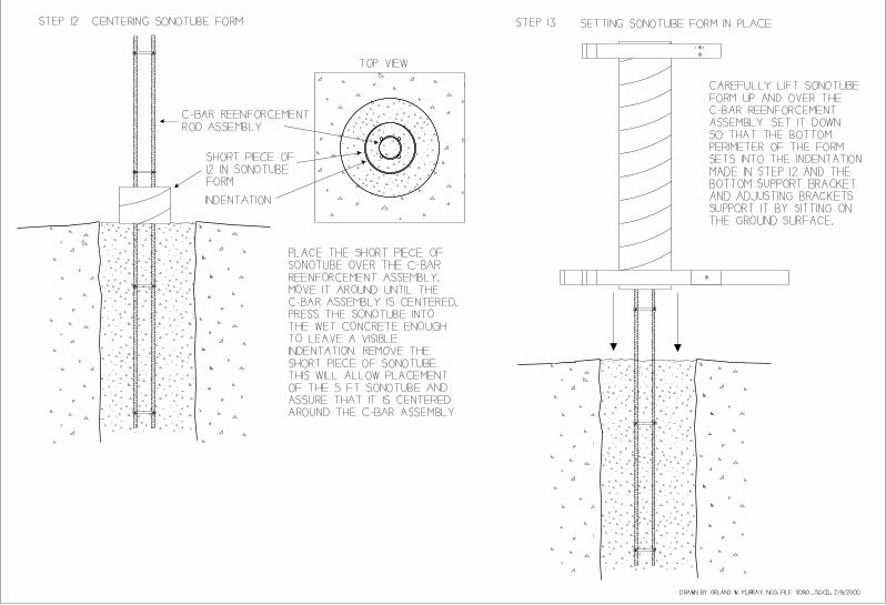
STEP 20 - Continue pouring and tamping the concrete until the Sonotube form is full to the top.Use a trowel to clean up and smooth the wet concrete. The pier is now ready for the installationof the antenna mount.
STEP 21 - Attaching Antenna Mount to Upper Pier - Place the antenna mount as close to thecenter of the top of pier as possible and press the legs into the wet cement. Wiggle the mount towork it in until the bottom of the Delrin plate touches the cement ( See Drawing - Step 21 FiguresA, B, C). Use a small stick to tamp the cement around the legs. Once the mount is at the surfaceof the cement, use a stick or hand of a trowel to gently tap the top of the Delrin plate to removeair bubbles from beneath it and settle it into the wet cement. Keep tapping around the plate untilit is imbedded no more than ½ inch (See Drawing - Step 21 D).


STEP 22 - Leveling the Antenna Mount - It is important the antenna mount be leveled before theconcrete cures. Remove the adapter plug (See Drawing - Step 22 A) and place a carpenters levelacross the center of the tribrach adapter (See Drawing - Step 22 B). While observing the bubbleon the level, rotate the level 30 degrees or so (See Drawing - Step 22 C) to determine in whatdirection the tribrach adapter is misleveled. With the level sitting on the tribrach adapter, gentlytap the top of the Delrin plate (See Drawing - Step 22 D) with the handle of the trowel until thelevel bubble is centered. Rotate the level around again to be sure the tribrach adapter is level in alldirections (See Drawing - Step 22 F).
STEP 23 - Use the trowel to smooth the top of the wet concrete. If possible, try to slope theconcrete to the outer edge of the pier so that water will run off and away from the adapter. Bevery careful not to disturb the antenna mount. When done smoothing, check the level of thetribrach adapter again to be sure it was not moved.
STEP 24 - Marking True North Direction - Carefully set a compass on the tribrach adapter andorient it to true north allowing for local declination. Make a arrow in the wet concrete or stick asmall bolt in the concrete to mark the direction to true north.
STEP 25 - Place a plastic bag over the top of the upper pier and tape it to the Sonotube form. This will protect the wet concrete from rain and birds, etc. while the concrete is curing. Be verycareful not to disturb the antenna mount and move it out of level. This completes the initialsetting of the recommended CORS monument. The following steps are to be done after theconcrete has cured for 3 to 7 days.
STEP 26 - After a period of 3 to 7 days, remove the Sonotube form from the upper pier. Theform is designed to peel in spiral. It has a spiral tear line along which it can be torn. Start at thetop where the spiral groove begins and start pulling the form away from the concrete. The easewith which the form comes off seems to depend on whether the form got wet during the curingtime. It may come of easy in some place and stick in others.
STEP 27 - After the concrete has cured a while, observe the line where the concrete meets theantenna mount Delrin base plate. If any separation should occur, seal the joint with RTV siliconeto prevent any water from getting in. The prototype CORS monument set at the NGS Instrumentand Methodologies Branch in Corbin, VA. showed no sign of separation after more than monthof curing. So this may not be a problem, but is worth checking.
STEP 28 - After the concrete has cured for a week or two, seal the joint between the upper andlower piers with concrete hydraulic cement. This will prevent any water from penetrating,freezing and possibly cracking the monument.
STEP 29 - After the concrete has cured for a couple of weeks or more, patch any holes left onthe surface of the upper pier with patching cement and paint the monument with a good qualityconcrete sealing paint. Use a white color which may reflect radiant heat and help stabilize thethermal expansion.


This completes the establishment of the NGS recommended CORS monument. Attaching theGPS antenna and running the cables to the receiver are not addressed in this guide.