procedures and products - ROE Dental Laboratory Catalog Nobel.pdfprocedures and products. ......
67
NobelActive ™ procedures and products
Transcript of procedures and products - ROE Dental Laboratory Catalog Nobel.pdfprocedures and products. ......

NobelActive™
procedures and products

Description Nobel Biocare manufactures dental implants from biocompatible titanium, and abutments from titanium and ceramic materials. The implants are supplied with various titanium and hydroxy apatite surfaces. Accessory restorative components are produced in gold alloy and polymers, as well as titanium.
Indications Nobel Biocare’s dental implants are used as the foundation for anchoring tooth replacements in either jaw. Restorations range from replacing one single tooth to an entire arch of bridgework, as well as retentive elements for overdenture applications. Dental implants are intended to be used in a manner in which they integrate with the bone (osseointegration).
Contraindications Pre-operative patient evaluation is necessary to determine any factors which put the patient at risk from the implant placement proce-dure itself, or factors that may affect healing capabilities of either the bone or associated soft tissue. Dental implants should not be used in patients who are unfi t medically for a general oral surgical procedure. For patients who have localized or systemic factors that could be expected to interfere with the healing process of either bone or soft tissue (e.g. connective tissue disorders, steroid therapy, infections in bone, cigarette smoking) the potential benefi ts and risks of treatment need to be carefully evaluated.
In addition, the patient needs to have an adequate volume of residual bone for placing suffi cient size and numbers of implants to support the anticipated functional loads to which the patient will subject these implants. Insuffi cient size or numbers of implants to support biomechanical loads or undesirable positioning of implants can lead to mechanical failures including fatigue frac-ture of implants, prosthetic screws and/or abutment screws. Particular caution should be used when placing narrow platform internal connection implants in the posterior region. Implant placement and prosthetic design must ac-commodate individual patient conditions such as bruxism or unfavorable jaw relationships to reduce the risk of overload or fatigue failure, and treatment is contraindicated if adequate accommodation cannot be accomplished. If inadequate bone volume is present, augmentation procedures can be con-sidered. Please consult appropriate clinical manuals and textbooks for informa-tion on treatment planning and medical evaluation (see above).
Warning Treatment planning and placement of dental implants requires special considerations compared to dentistry in general. It is recommended that practitioners take courses with hands-on training to learn proper tech-niques, including biomechanical requirements and radiographic evaluation. Improper technique in either implant placement or restoration can result in implant failure and substantial loss of surrounding bone.
Drilling procedures for implant placement use specifi c drill measurement systems and reference points unique for each system listed below:
• Replace® Select Tapered • NobelActive™
• Replace® Select Straight • NobelSpeedy™
• Brånemark System® • NobelReplace™
• NobelDirect® • NobelPerfect®
• NobelDirect® 3.0 • Brånemark System® Zygoma Implants • Nobel Biocare Immediate Provisional Implant
The practitioner is directed to the measurement description in the appropriate clinical manual, specifi c to the implant system selected (see above) before any drill preparation takes place around vital structures. Each implant system has unique measuring characteristics to allow full seating of the implant to the desired depth. In some instances, drill length reference lines measure longer than the stated length of the implant. It is recommended that the implant surgeon be thoroughly familiar with the specifi c measurement sys-tem being utilized and provide a suitable safety margin adjacent to any teeth and vital structures. Failure to recognize actual lengths of drills relative to radiographic measurements can result in permanent injury to nerves or other vital structures by drilling beyond the depth intended, potentially resulting in permanent numbness to the lower lip and chin from lower jaw surgery or other injury.
Each implant system has specifi c design characteristics for mating implants, abutments and prosthetic components. Combining components that are not confi gured or dimensioned for correct mating can lead to mechanical failure of components, damage to tissue, or unsatisfactory esthetic results.
One-hundred percent success cannot be guaranteed. Lack of adequate quan-tity and/or quality of remaining bone, infection and generalized diseases are some potential causes for failure of osseointegration both immediately after surgery, or after osseointegration is initially achieved. Pre-operative hard tissue or soft tissue defi cits may yield a compromised esthetic result or unfavorable implant angulation. With respect to children, routine treatment is not recom-mended until growth has stopped and epiphyseal closure has occurred.
Sterility All implants, and various abutments (see labels) are shipped sterile, and are for single use only prior to the labeled expiration date. Do not use implants if the packaging has been damaged or previously opened. Abutments that are delivered sterile and have never been used in the oral cavity may be re-sterilized. (See manuals listed above). Abutments not delivered sterile should be sterilized prior to use using steam sterilization at 135 °C for fi ve minutes. Products not provided sterile by the manufacturer must be cleaned and sterilized (if indicated) according to the instructions in the appropriate manual before intra-oral use (see above). For steam sterilization of kits (not applicable for Try-in Abutment Kit Box and Brånemark System® Zygoma Surgical Kit Box), sterilize at 134°C/274°F, for 6 minutes .
General Precautions Surgical and restorative products used to achieve and maintain osseointegration as described by Professor Brånemark, et al., should be utilized by persons trained in this method. Such training is offered at a number of centers. Please contact manufacturer for information. Each patient must be carefully examined and evaluated to determine radiographic, psychological and physical status. Additionally, the patient’s teeth and any associated bone or soft tissue defi cits that will infl uence the fi nal result should also be evaluated. Close cooperation between surgeon, restorative dentist and dental laboratory technician is essential for success.
Procedural Precautions, Surgery All efforts must be made to minimize damage to the host tissue, paying special attention to thermal and surgical trauma and to the elimination of contaminants and sources of infection. The surgical procedure requires a high degree of precision and care, and the limits for acceptable tissue handling are much narrower than in general oral surgery. Any divergence from the principle of least possible trauma at implant installation increases the risk of failure to establish osseointegration. Tilting implants – implants may be tilted up to 45°. If the angulation is 30° or more, it is necessary to splint the tilted implants. All drilling procedures should be performed at low speed (approximately 800 rpm for tapered drills and up to 2000 rpm for straight drills). Pre-tapping (threading of the bone) and implant placement should be accomplished at very low speed (~ 25–30 rpm) or manually. All drilling and pre-tapping procedures require the use of dedicated, sharp instruments under constant and profuse irrigation for cooling. Implants are ideally installed in a stable manner; however, excessive insertion torque (greater than 45–50 Ncm) to overcome bone resistance may lead to damage to the implant; fracture or necrosis of the bone site (see appropriate clinical manuals). All instruments used in surgery must be maintained in good condition and care must be taken that instrumentation does not damage implants or other components. Because of the small size of implant components and instruments, care must be taken that they are not swallowed or aspirated by the patient. After the implant installation, the surgeon’s evaluation of bone quality and initial stability will determine when implants may be loaded.
Procedural Precautions, Prosthetics Especially important is proper stress distribution: passive adaptation and fi tting of the bridge to the implant abutments; adjusting occlusion to the opposing jaw; avoiding excessive transverse loading forces, particularly in immediate loading cases. If the prosthesis metal substructure is made of gold alloy, this should have a high gold content. Because of the small size of prosthetic components, care must be taken that they are not swallowed or aspirated by the patient.
Adverse Effects Implant techniques have normal contraindications and risks. These are extensively documented in the dental literature.
Caution The caution text “Federal (USA) law restricts the sale of this device to, or on the order of, a licensed physician or dentist” is shown on labels with “Rx Only”.
Important! Please read
Manufacturer: Nobel Biocare AB, Box 5190, SE-402 26 Göteborg, Sweden.Phone: +46 31 81 88 00. Fax: +46 31 16 31 52 www.nobelbiocare.com
precautions and warnings

important
Important aspects of treatment with NobelActive™
• We strongly recommend that practitioners, new as well as experienced implant users, always go through special training before undertaking a new treatment method. Nobel Biocare provides a wide range of courses for various levels of knowledge. For more information on the courses we have to offer,visit our website: nobelbiocare.com, or consult our course catalog.
• Always work with an experienced colleague the fi rst time you employ a new treatment method. Nobel Biocare has a global network of mentors available for this purpose.
• Read this manual carefully before starting treatment. The treatment must follow the manual precisely to be successful.
• Read also the general user instructions for use carefully before starting treatment.
1. Full seating of implant
The unique thread design allows the implant to be redirected during insertion. However, this feature needs attention during placement, as the implant will not necessarily stop at the bottom of the prepared site.
2. Insertion speed of implant
The threadpitch allows the implant to be inserted up to four times faster compared to other implants. This means that less turns are required to fully seat the implant.
3. Implant insertion
If the Surgical Driver is used to insert the implant, special care needs to be taken to avoid overtightening.
3
Important . . . . . . . . . . . . . . . . . . . . . . . . . . . . . . . . . . . . . . . . . . . . . . . . . . . . . . . . . . . . . . . . . . . . . . . . . . . . . . . . . . . . . . . . . . . . . . . . . . . . . . . . . . . . . . . . 3
Quick start NobelActive™
. . . . . . . . . . . . . . . . . . . . . . . . . . . . . . . . . . . . . . . . . . . . . . . . . . . . . . . . . . . . . . . . . . . . . . . . . . . . . . . . . . . . . . . . . . . . . . . . . . . . . . . . . . 5
Overview . . . . . . . . . . . . . . . . . . . . . . . . . . . . . . . . . . . . . . . . . . . . . . . . . . . . . . . . . . . . . . . . . . . . . . . . . . . . . . . . . . . . . . . . . . . . . . . . . . . . . . . . . . . . 6–7
Surgical proceduresNobelActive™ – Expands treatment options . . . . . . . . . . . . . . . . . . . . . . . . . . . . . . . . . . . . . . . . . . . . . . . . . . . . . . . . . . . 8
Examination and treatment planning . . . . . . . . . . . . . . . . . . . . . . . . . . . . . . . . . . . . . . . . . . . . . . . . . . . . . . . . . . . . . . . . . . . . 9
Surgical procedures . . . . . . . . . . . . . . . . . . . . . . . . . . . . . . . . . . . . . . . . . . . . . . . . . . . . . . . . . . . . . . . . . . . . . . . . . . . . . . . . . . . . . . . . . . . . . . 10
Technical specifi cations . . . . . . . . . . . . . . . . . . . . . . . . . . . . . . . . . . . . . . . . . . . . . . . . . . . . . . . . . . . . . . . . . . . . . . . . . . . . . . . . . . . . . . . . 11
Drill sequence & depth . . . . . . . . . . . . . . . . . . . . . . . . . . . . . . . . . . . . . . . . . . . . . . . . . . . . . . . . . . . . . . . . . . . . . . . . . . . . . . . . . . 12–13
Step-by-step clinical procedure . . . . . . . . . . . . . . . . . . . . . . . . . . . . . . . . . . . . . . . . . . . . . . . . . . . . . . . . . . . . . . . . . . . . . . 14–21
Special surgical procedures . . . . . . . . . . . . . . . . . . . . . . . . . . . . . . . . . . . . . . . . . . . . . . . . . . . . . . . . . . . . . . . . . . . . . . . . . . . . 22–26
Finalization procedures NobelActive™ . . . . . . . . . . . . . . . . . . . . . . . . . . . . . . . . . . . . . . . . . . . . . . . . . . . . . . . . . . . . . . . . . . 27
Prosthetic proceduresUnique prosthetic connection . . . . . . . . . . . . . . . . . . . . . . . . . . . . . . . . . . . . . . . . . . . . . . . . . . . . . . . . . . . . . . . . . . . . . . . . 28–29
Immediate Function™ – Procera® Esthetic Abutment . . . . . . . . . . . . . . . . . . . . . . . . . . . . . . . . . . . . . . 30–31
Immediate Function™ – QuickTemp™ Abutment . . . . . . . . . . . . . . . . . . . . . . . . . . . . . . . . . . . . . . . . . . . . 32–33
Procera® Abutment Zirconia . . . . . . . . . . . . . . . . . . . . . . . . . . . . . . . . . . . . . . . . . . . . . . . . . . . . . . . . . . . . . . . . . . . . . . . . . . . 34–36
Esthetic Abutment . . . . . . . . . . . . . . . . . . . . . . . . . . . . . . . . . . . . . . . . . . . . . . . . . . . . . . . . . . . . . . . . . . . . . . . . . . . . . . . . . . . . . . . . . . 37–39
Snappy Abutment™ . . . . . . . . . . . . . . . . . . . . . . . . . . . . . . . . . . . . . . . . . . . . . . . . . . . . . . . . . . . . . . . . . . . . . . . . . . . . . . . . . . . . . . . . 40–42
Multi-unit Abutment . . . . . . . . . . . . . . . . . . . . . . . . . . . . . . . . . . . . . . . . . . . . . . . . . . . . . . . . . . . . . . . . . . . . . . . . . . . . . . . . . . . . . 43–46
Procera® Implant Bridge Zirconia . . . . . . . . . . . . . . . . . . . . . . . . . . . . . . . . . . . . . . . . . . . . . . . . . . . . . . . . . . . . . . . . . . . 47–48
Procera® Implant Bridge Titanium . . . . . . . . . . . . . . . . . . . . . . . . . . . . . . . . . . . . . . . . . . . . . . . . . . . . . . . . . . . . . . . . . . 49–51
AppendicesAppendix I – Kits . . . . . . . . . . . . . . . . . . . . . . . . . . . . . . . . . . . . . . . . . . . . . . . . . . . . . . . . . . . . . . . . . . . . . . . . . . . . . . . . . . . . . . . . . . . . 52–53
Appendix II – NobelActive™ Manual Torque Wrench. . . . . . . . . . . . . . . . . . . . . . . . . . . . . . . . . . . . . . . . . . . 54
Appendix III – use of Drill Stop . . . . . . . . . . . . . . . . . . . . . . . . . . . . . . . . . . . . . . . . . . . . . . . . . . . . . . . . . . . . . . . . . . . . . . . . . . . . . 55
Appendix IV – cleaning and sterilization . . . . . . . . . . . . . . . . . . . . . . . . . . . . . . . . . . . . . . . . . . . . . . . . . . . . . . . . . . . . . . 56
Procera® Esthetic Abutment . . . . . . . . . . . . . . . . . . . . . . . . . . . . . . . . . . . . . . . . . . . . . . . . . . . . . . . . . . . . . . . . . . . . . . . . . . . . . . . . . 57
Product catalogSurgical components overview . . . . . . . . . . . . . . . . . . . . . . . . . . . . . . . . . . . . . . . . . . . . . . . . . . . . . . . . . . . . . . . . . . . . . . 58–59
Product specifi cations . . . . . . . . . . . . . . . . . . . . . . . . . . . . . . . . . . . . . . . . . . . . . . . . . . . . . . . . . . . . . . . . . . . . . . . . . . . . . . . . . . . . 60–61
Reference guide Index in alphabetical order . . . . . . . . . . . . . . . . . . . . . . . . . . . . . . . . . . . . . . . . . . . . . . . . . . . . . . . . . . . . . . . . . . . . . . . . . . . . 62–63Index in numeric order . . . . . . . . . . . . . . . . . . . . . . . . . . . . . . . . . . . . . . . . . . . . . . . . . . . . . . . . . . . . . . . . . . . . . . . . . . . . . . . . . . 64–65
table of contents
4

quick start
Products needed for implant placement:
• NobelActive™ Surgery Kit
• NobelActive™ implants
• Disposable Drills
• Bone Mill with Guide NobelActive™ Internal (optional)
Products needed for Temporization/Immediate Function™
• QuickTemp™ Abutment NobelActive™ Internal (multiple units)
• Immediate Temporary Abutment NobelActive™ Internal (single units)
• Prosthetic Kit
Quick start – NobelActive™
NobelActive™ Surgery Kit
Product illustrations are not to scale 5

quick start
See table on page 13 for drill sequences for all platforms and
different bone types.
Twist Step Drill ∅ 2.4/2.8mm Twist Step Drill ∅ 3.2/3.6mm
Flapless technique
Twist Drill w Tip ∅ 2mm
Flap technique
Twist Drill w Tip ∅ 2mm
Product illustrations are not to scale6

quick start
Implant Placement
One-Stage Delayed Function
One-Stage Immediate Function™
Product illustrations are not to scale
Two-Stage Delayed Function
7
surgical procedures
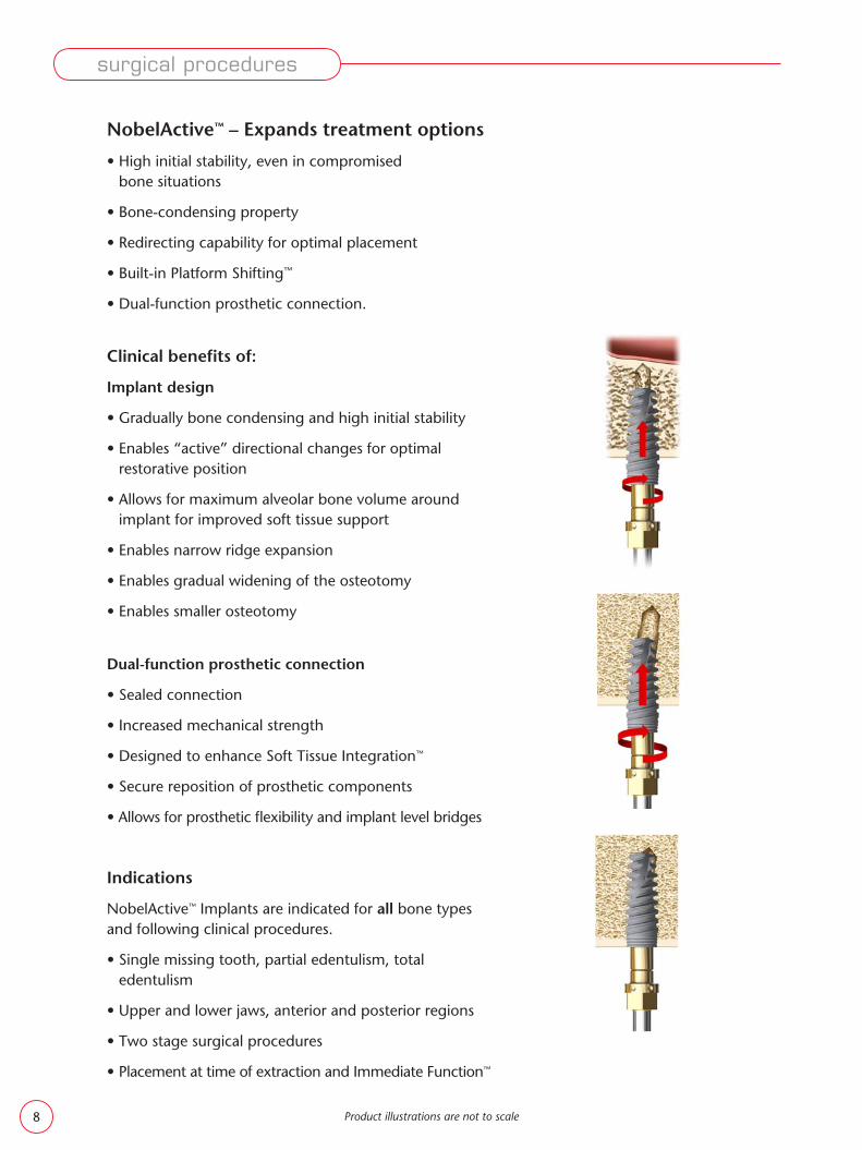
NobelActive™ – Expands treatment options
• High initial stability, even in compromised bone situations
• Bone-condensing property
• Redirecting capability for optimal placement
• Built-in Platform Shifting™
• Dual-function prosthetic connection.
Clinical benefi ts of:
Implant design
• Gradually bone condensing and high initial stability
• Enables “active” directional changes for optimal restorative position
• Allows for maximum alveolar bone volume around implant for improved soft tissue support
• Enables narrow ridge expansion
• Enables gradual widening of the osteotomy
• Enables smaller osteotomy
Dual-function prosthetic connection
• Sealed connection
• Increased mechanical strength
• Designed to enhance Soft Tissue Integration™
• Secure reposition of prosthetic components
• Allows for prosthetic fl exibility and implant level bridges
Indications
NobelActive™ Implants are indicated for all bone types and following clinical procedures.
• Single missing tooth, partial edentulism, total edentulism
• Upper and lower jaws, anterior and posterior regions
• Two stage surgical procedures
• Placement at time of extraction and Immediate Function™
Product illustrations are not to scale8

surgical procedures
Examination and treatment planning
Carry out examination and treatment planning according to the routines of the clinic.
Bear in mind that in the majority of cases the implant’s special abilities may reduce the need for an additional surgical procedure of bone augmentation prior to the implant placement session. The implant can be stabilized in minimal bone and bone augmentation can be carried out in the same session.
Bone quality
Traditionally, dense compact bone provides good initial stabilization for the installed implant while cancellous bone provides much reduced retention and therefore more bone to implant contact is necessary for a suffi cient initial stabilization.
Vertical bone quantity
The amount of bone available for implant retention differs from site to site.
The unique design features of NobelActive™ allow it to be anchored and stabilized in minimal bone anywhere along the length of the implant.
The implant is “active” enabling an angle change dur-ing insertion. This ability facilitates engaging it parallel to palatal bone walls allowing expanding the palatal aspect of the socket in the facial direction (see p. 25–26).
Horizontal bone quantity
To maintain vertical tissue dimension, make sure to allow at least 1.5mm of bone lingual to and buccal to the implant collar. The special narrowing of the implant collar diameter allows for favorable ridge adaptation when crestal ridge width is limited.
Product illustrations are not to scale 9

Surgical procedures
Use fl apless technique when:
• There is suffi cient quantity and quality of alveolar bone and soft tissue
• It is not necessary to refl ect a fl ap to safely direct drilling procedure in relation to the anatomy
• Flapless procedure: measure soft tissue thickness with a probe. Add tissue thickness to drilling depth for correct site preparation.
Use fl ap technique when:
• It is necessary to observe the underlying alveolar bone and adjacent anatomical structures
• Placing bone and/or connective tissue grafts
Caution! Confi rm available bone and signifi cant anatomical landmarks such as blood vessels, nerves, and concavities with conventional diagnostic tools such as radiographic imaging, probing and palpation.
surgical procedures
Product illustrations are not to scale10

Technical specifi cations
• Conical 2-piece implant with a unique combination of design features that enable easy insertion and very high initial stability
• New internal connection using conical seating and hexagon interlocking
Platforms
To facilitate treatment planning, clinical procedures, and component identifi cation, NobelActive™ Implants are organized according to a “platform concept”.
The platform marking corresponds to the implant-abutment interface.
For component identifi cation prosthetic components for Narrow Platform (NP) are color coded in magenta.
Measurements are in mm.
Platform Platform Implant Abutment Lengths diameter diameter interface
surgical procedures
Product illustrations are not to scale
Narrow Platform: Limited inter-dental space. Not enough alveolar bone for an RP implant.
Note! Narrow Platform implants are not recommended to be used in the posterior region.
∅ 3.5 ∅ 3.5 ∅ 3.0 10 11.5 13 15
∅ 4.3 ∅ 3.4 10 11.5 13 15 ∅ 3.9 ∅ 5.0 ∅ 3.4 10 11.5 13 15
11

Image show Twist and Twist Step Drills 7–15mm and implant 13mm.
surgical procedures
Drill sequence
The drills are made from surgical stainless steel and coated with an amorphous diamond coating which gives them their black color. The drills are used with external irrigation.
• Drills are available in two length versions, 10–18mm and 7–15mm. See height markings on image.
• Use an in-and-out motion and drill in bone for 1–2 seconds
• Move drill out without stopping handpiece motor. This allows the irrigation to fl ush away debris.
• Proceed with this method to drill to a suitable depth in accordance with bone quality and implant diameter
• Stop drilling if there is no irrigation
• When using the Drill Extension shaft, it is important to supplement cooling at the tip of the drill with manual irrigation as necessary.
The Drill Extension Shaft is intended for use with Twist Drill used for site preparation; it is not recommended for use with screw taps or implant drivers.
Caution! The drill preparation extends up to 1mm longer than the implant. Allow for this additional length when drilling near vital anatomical structures.
Note! Twist Drills and Twist Step Drills are disposable and should be used for one surgery only. Do not re-sterilize a disposable drill.
Depth measurement system
All drills and components are marked to enable you to prepare the site to the correct depth and obtain a secure and predictable position.
Note! The marks on the twist drills (7, 10, 13, and 15)indicate actual millimeter lengths and correspond to the top of the implant collar.
Final vertical positioning depends on several clinical parameters such as:
• Esthetics• Tissue thickness• Available vertical height• Flapless procedure: measure soft tissue thickness with
a probe. Add tissue thickness to drilling depth for correct site preparation.
Image show Twist Drills 10–18mm, 7–15mm and implant 13mm.
Product illustrations are not to scale12
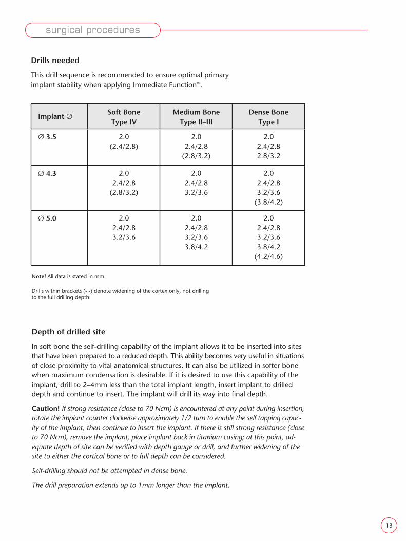
Depth of drilled site
In soft bone the self-drilling capability of the implant allows it to be inserted into sites that have been prepared to a reduced depth. This ability becomes very useful in situations of close proximity to vital anatomical structures. It can also be utilized in softer bone when maximum condensation is desirable. If it is desired to use this capability of the implant, drill to 2–4mm less than the total implant length, insert implant to drilled depth and continue to insert. The implant will drill its way into fi nal depth.
Caution! If strong resistance (close to 70 Ncm) is encountered at any point during insertion, rotate the implant counter clockwise approximately 1/2 turn to enable the self tapping capac-ity of the implant, then continue to insert the implant. If there is still strong resistance (close to 70 Ncm), remove the implant, place implant back in titanium casing; at this point, ad-equate depth of site can be verifi ed with depth gauge or drill, and further widening of the site to either the cortical bone or to full depth can be considered.
Self-drilling should not be attempted in dense bone.
The drill preparation extends up to 1mm longer than the implant.
Drills needed
This drill sequence is recommended to ensure optimal primary implant stability when applying Immediate Function™.
Implant ∅ Soft BoneType IV
Medium BoneType II–III
Dense BoneType I
∅ 3.5 2.0(2.4/2.8)
2.02.4/2.8
(2.8/3.2)
2.02.4/2.82.8/3.2
∅ 4.3 2.02.4/2.8
(2.8/3.2)
2.02.4/2.83.2/3.6
2.02.4/2.83.2/3.6
(3.8/4.2)
∅ 5.0 2.02.4/2.83.2/3.6
2.02.4/2.83.2/3.63.8/4.2
2.02.4/2.83.2/3.63.8/4.2
(4.2/4.6)
Note! All data is stated in mm.
Drills within brackets (- -) denote widening of the cortex only, not drilling to the full drilling depth.
surgical procedures
13

surgical procedures
NobelActive™ Internal RP 4.3
Illustration shows the drill sequence for NobelActive™ Internal RP 4.3 × 13mm in medium bone.
For NobelActive™ implants with diameter 3.5 and 5.0mm as well as drill protocol in various bone densities, please refer to the sequence table on page 13.
Step-by-step clinical procedure
• Drill to the appropriate depth using the Twist Drill with Tip ∅ 2mm. Drill Stops can be used.
Note! When using a fl apless procedure, measure the soft tissue thickness with a probe. Add this tissue thickness to the drilling depth for correct site preparation. Be aware of anatomical landmarks.
• Check orientation using Direction Indicator ∅ 2.0/2.4–2.8mm
• If applicable, take a radiograph to verify correct direction
• When placing multiple implants, proceed to next implant site before continuing to next drill sequence
Twist Drill with Tip ∅ 2mm
Max 2000 rpm
High speed
Flapless Flap
Product illustrations are not to scale
Flapless Flap• To facilitate initial penetration and creation of a crestal start
point, a Precision Drill can be used before Twist Drill with Tip ∅ 2mm
Precision Drill
Max 2000 rpm
High speed
OPTIONAL
14

• Continue site preparation using Twist Step Drill ∅ 3.2/3.6mm
• Use Depth Probe to verify the desired depth has been achieved (including soft tissue thickness, if applicable)
Twist Step Drill ∅ 3.2/3.6mm
Determine implant length
Flapless Flap
Flapless Flap
Max 2000 rpm
High speed
surgical procedures
Flapless Flap• Continue site preparation using Twist Step Drill ∅ 2.4/2.8mm
• Check orientation using Direction Indicator ∅ 2.0/2.4–2.8mm
Twist Step Drill ∅ 2.4/2.8mm
Max 2000 rpm
High speed
Product illustrations are not to scale 15

Depending on the clinical situation and accessibility, there are three different options to insert the NobelActive™ implant:
surgical procedures
• Each implant is packaged in a double aseptic vial
• The outer package has a printed label with product data. Record implant size and LOT number on patient’s chart.
• Two peel-off labels on outer vial can be affi xed directly to chart
• The outer implant vial cap is color coded to identify the implant platform. A label marks implant diameter and length.
• Lift off plastic cap to gain access to implant. (No cover screw co-packed with implant.)
It is possible to start the implant insertion manually, using the NobelActive™ Implant Driver and Surgical Wrench Adapter
The maximum tightening torque for the implant is 70 Ncm and may be measured with NobelActive™ Manual Torque Wrench Surgical.
Caution! Overtightening may compromise the integrity of the internal connection and overcompress the surrounding bone, compromising osseointegration.
1. Using the NobelActive™ Manual Torque Wrench Surgical
2. Using the Surgical Driver
Caution! Avoid overtightening of the implant. Overtightening may compromise the integrity of internal connection and over-compress the surrounding bone, compromising osseointegration.
3. Using a drilling unit
Packaging
Implant insertion
Product illustrations are not to scale16

surgical procedures
Pick-up Implant
• Connect Implant Driver NobelActive™ Internal (A) to the NobelActive™ Manual Torque Wrench Surgical (B)
Using NobelActive™ Manual Torque Wrench
A
B
• Pick up implant by applying light pressure on implant driver
• Start inserting the implant into the osteotomy
Product illustrations are not to scale
Make sure that the Implant Driver is fully seated.
17

A
B
surgical procedures
Pick-up Implant
• In anterior areas, a Surgical Driver may be used to place the implant
• Connect Implant Driver NobelActive™ Internal (A) to the Surgical Driver (B)
Using Surgical Driver
• Pick up implant by applying light pressure on implant driver.
Note! The Surgical Driver is designed to be used while grasped with fi nger pressure only. Use of full palm grip can yield over 200 Ncm insertion torque.
• Start inserting the implant into the osteotomy
Caution! Avoid overtightening of the implant. Overtightening may compromise the integrity of internal connection and over-compress the surrounding bone, compromising osseo integration.
Product illustrations are not to scale
Make sure that the Implant Driver is fully seated.
18

surgical procedures
Pick-up Implant
• Connect Implant Driver NobelActive™ Internal to handpiece
Using a drilling unit
• Pick up implant by applying light pressure on implant driver
• Start inserting the implant into the osteotomy using low speed (25 rpm). The drilling unit may be set to the maximum 50 Ncm insertion torque.
Product illustrations are not to scale
Make sure that the Implant Driver is fully seated.
19

• Connect the NobelActive™ Manual Torque Wrench Surgical to the Manual Torque Wrench Adapter and place implant to fi nal depth
• For Immediate Function™, the implant should be able to withstand a fi nal tightening torque of at least 35 Ncm. Do not exceed 70 Ncm.
• Align driver with implant during installation
• Remove driver with an easy upward motion
Caution! Excessive force while inserting the implant with the wrench or implant driver must be avoided. It can cause undue compression of the bone and result in necrosis and impaired results. If strong resistance (close to 70 Ncm) is encountered at any point during insertion, rotate the implant counter clockwise approximately 1/2 turn to enable the self tapping capacity of the implant, then continue to insert the implant. If there is still strong resistance (close to 70 Ncm), remove the implant, place implant back in titanium casing; at this point, adequate depth of site can be verifi ed with depth gauge or drill, and further widening of the site to either the cortical bone or to full depth can be considered.
Note! Removal of implant driver: If the implant driver is diffi cult to remove, slightly rotate it counter clockwise before lifting it up.
surgical procedures
Final tightening
Product illustrations are not to scale20

• For maximum esthetic results place the implant on the level of the buccal bone or 0.5–1mm below
Final implant placement
• When placing the implant, align one of the dots on the Implant Driver NobelActive™ Internal parallel to the buccal/facial wall. This positions the internal hexagon to ensure preferred prosthetic abutment orientation.
Implant orientation
l b
• Implant Driver NobelActive™ Internal has a 3mm height marking to facilitate vertical implant positioning when using a fl apless procedure
Note! Removal of implant driver: If the implant driver is diffi cult to remove, slightly rotate it counter clockwise before lifting it up.
surgical procedures
Product illustrations are not to scale 21
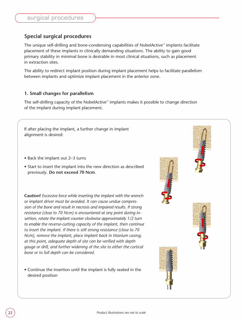
If after placing the implant, a further change in implant alignment is desired:
• Back the implant out 2–3 turns
• Start to insert the implant into the new direction as described previously. Do not exceed 70 Ncm.
Caution! Excessive force while inserting the implant with the wrench or implant driver must be avoided. It can cause undue compres-sion of the bone and result in necrosis and impaired results. If strong resistance (close to 70 Ncm) is encountered at any point during in-sertion, rotate the implant counter clockwise approximately 1/2 turn to enable the reverse-cutting capacity of the implant, then continue to insert the implant. If there is still strong resistance (close to 70 Ncm), remove the implant, place implant back in titanium casing; at this point, adequate depth of site can be verifi ed with depth gauge or drill, and further widening of the site to either the cortical bone or to full depth can be considered.
• Continue the insertion until the implant is fully seated in the desired position
Special surgical procedures
The unique self-drilling and bone-condensing capabilities of NobelActive™ implants facilitate placement of these implants in clinically demanding situations. The ability to gain good primary stability in minimal bone is desirable in most clinical situations, such as placement in extraction sites.
The ability to redirect implant position during implant placement helps to facilitate parallelism between implants and optimize implant placement in the anterior zone.
1. Small changes for parallelism
The self-drilling capacity of the NobelActive™ implants makes it possible to change direction of the implant during implant placement.
Product illustrations are not to scale
surgical procedures
22

Product illustrations are not to scale
2. Stabilization in wide sockets with minimal bone
The unique design features of the NobelActive™ implants allow it to be anchored and stabilized in minimal bone.
Note! In these situations, a one-stage surgical approach is not recommended.
• Due to the special design it is possible to insert NobelActive™ implants into prepared sites of much narrower diameter than required for implants in general
• Drill apically in the extraction socket, using Twist Drill w Tip ∅ 2
• Depending on the diameter of the implant and bone density, continue site preparation, using the drilling protocol described on page 13
• Start to insert the implant into the under prepared site as described previously. Do not exceed 70 Ncm.
Caution! Excessive force while inserting the implant with the wrench or implant driver must be avoided. It can cause undue compression of the bone and result in necrosis and impaired results. If strong resist-ance (close to 70 Ncm) is encountered at any point during insertion, rotate the implant counter clockwise approximately 1/2 turn to ena-ble the reverse-cutting capacity of the implant, then continue to in-sert the implant. If there is still strong resistance (close to 70 Ncm), remove the implant, place implant back in titanium casing; at this point, adequate depth of site can be verifi ed with depth gauge or drill, and further widening of the site to either the cortical bone or to full depth can be considered.
• Due to the unique thread design and bone-condensing capac-ity, suffi cient retention and stabilization may be achieved
• Bone augmentation may be immediately followed if indicated
• Place a Cover Screw NobelActive™ Internal and suture
surgical procedures
23

Product illustrations are not to scale
surgical procedures
3. Stabilization in soft bone
The unique design of the NobelActive™ implant allows insertion into small diameter osteotomies and gradual bone condensing in all directions throughout the entire length of the implant.
• Drill using Twist Drill w Tip ∅ 2mm
• Depending on the diameter of the implant and bone density, continue to drill, using the drilling protocol described on page 13
• Start to insert the implant into the under-prepared site as described previously. Do not exceed 70 Ncm.
Caution! Excessive force while inserting the implant with the wrench or implant driver must be avoided. It can cause undue compression of the bone and result in necrosis and impaired results. If strong resistance (close to 70 Ncm) is encountered at any point during insertion, rotate the implant counter clockwise approximately 1/2 turn to enable the reverse-cutting capacity of the implant, then con-tinue to insert the implant. If there is still strong resistance (close to 70 Ncm), remove the implant, place implant back in titanium casing; at this point, adequate depth of site can be verifi ed with depth gauge or drill, and further widening of the site to either the cortical bone or to full depth can be considered.
• Due to the unique thread design and bone-condensing capacity, suffi cient retention and stabilization may be achieved all around the implant
24

4. Changing direction (Active placement)
Achieving esthetic results in the anterior maxilla is very diffi cult and considered a highly demanding treatment. The buccal bone plate is usually very thin and oftentimes missing altogether, whereas maintaining bone height and soft tissue architecture requires at least 1.5mm of bone thickness buccal to the implant.
In order to achieve the desired results, bone augmentation must often be performed prior to implant placement. In many cases NobelActive™ implants simplify this procedure.
The ability to self drill and actively change direction with the implant allows anchorage of the implant adjacent to the pala-tal wall with excellent stability leaving ample space for bone augmentation on the buccal aspect.
Thus tooth extraction, implant placement, bone augmentation and even immediate function can all be done in one session.
surgical procedures
• For maxillary anterior teeth, the objective is to utilize bone pala-tal to the remaining socket in the apical 1/3 to 1/2 for stabiliza-tion of the implant. The palatal wall is fi rst penetrated from a more perpendicular approach to gain a starting point with either the Precision Drill or the Twist Drill with Tip ∅ 2mm.
Note! When using a fl apless procedure, measure the soft tissue thickness with a probe. Add this tissue thickness to the drilling depth for correct site preparation. Be aware of anatomical landmarks.
• Continue to drill with the Twist Drill w Tip ∅ 2mm, while gradually changing the direction to a more vertical direction
Depending on the diameter of the implant and bone density, continue to drill as described above, using the drilling protocol described on page 13.
Drill sequence
The tooth is extracted and the socket is prepared in the regular manner.
Product illustrations are not to scale
• For creation of a start point in the palatal wall of the extraction socket, a Precision Drill can be used before Twist Drill with Tip ∅ 2mm
Precision Drill
Max 2000 rpm
High speed
OPTIONAL
25
Product illustrations are not to scale
surgical procedures
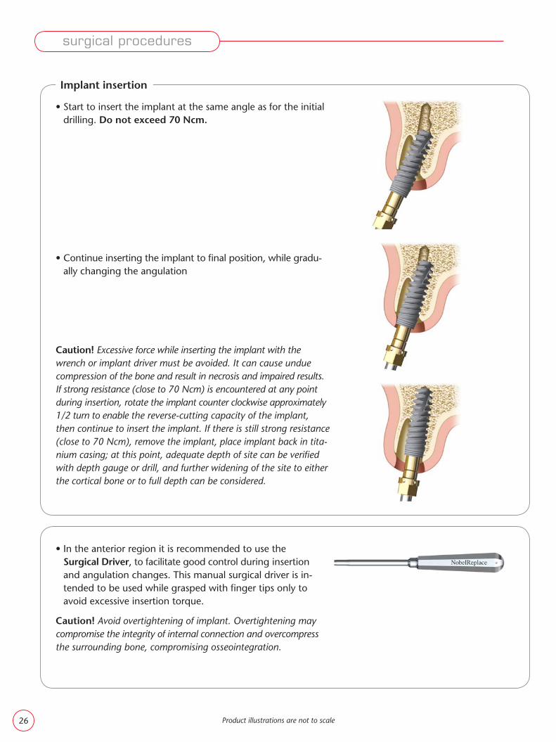
• Start to insert the implant at the same angle as for the initial drilling. Do not exceed 70 Ncm.
• Continue inserting the implant to fi nal position, while gradu-ally changing the angulation
Caution! Excessive force while inserting the implant with the wrench or implant driver must be avoided. It can cause undue compression of the bone and result in necrosis and impaired results. If strong resistance (close to 70 Ncm) is encountered at any point during insertion, rotate the implant counter clockwise approximately 1/2 turn to enable the reverse-cutting capacity of the implant, then continue to insert the implant. If there is still strong resistance (close to 70 Ncm), remove the implant, place implant back in tita-nium casing; at this point, adequate depth of site can be verifi ed with depth gauge or drill, and further widening of the site to either the cortical bone or to full depth can be considered.
Implant insertion
• In the anterior region it is recommended to use the Surgical Driver, to facilitate good control during insertion and angulation changes. This manual surgical driver is in-tended to be used while grasped with fi nger tips only to avoid excessive insertion torque.
Caution! Avoid overtightening of implant. Overtightening may compromise the integrity of internal connection and overcompress the surrounding bone, compromising osseointegration.
26

Bone Mill
Bone Mill with Guide NobelActive™ Internal NP
Bone Mill with Guide NobelActive™ Internal RP
Note! If bone above the implant platform inter-feres with complete seating of any components, the Bone Mill with Guide is used either manually or at low speed in the handpiece to clear a path of insertion.
Finalization procedures NobelActive™
There are three options for fi nalizing implant surgery with NobelActive™ implants.
One-stage Immediate Function™
Two-stage delayed function
Provisionalize implant for immediate esthetics and function using Nobel Biocare temporary compo-nents or fi nal abutments (see following procedures).
Use a Screwdriver Unigrip™ to connect Healing Abutment NobelActive™ Internal. If applicable, suture back the soft tissue.
Note! If an implant level Procera® Implant Bridge is planned to be connected to the implant, a Healing Abutment Bridge NobelActive™ Internal, should be used.
Use Screwdriver Unigrip™ to connect Cover Screw NobelActive™ Internal.
Suture tissue fl ap using desired technique.
surgical procedures
Product illustrations are not to scale
One-stage delayed function
27
30
Product illustrations are not to scale
Page
Procera® Esthetic AbutmentNobelActive™ Internal
32QuickTemp™ AbutmentNobelActive™ Internal (multiple units)
Immediate Temporary AbutmentNobelActive™ Internal (single restorations)
33
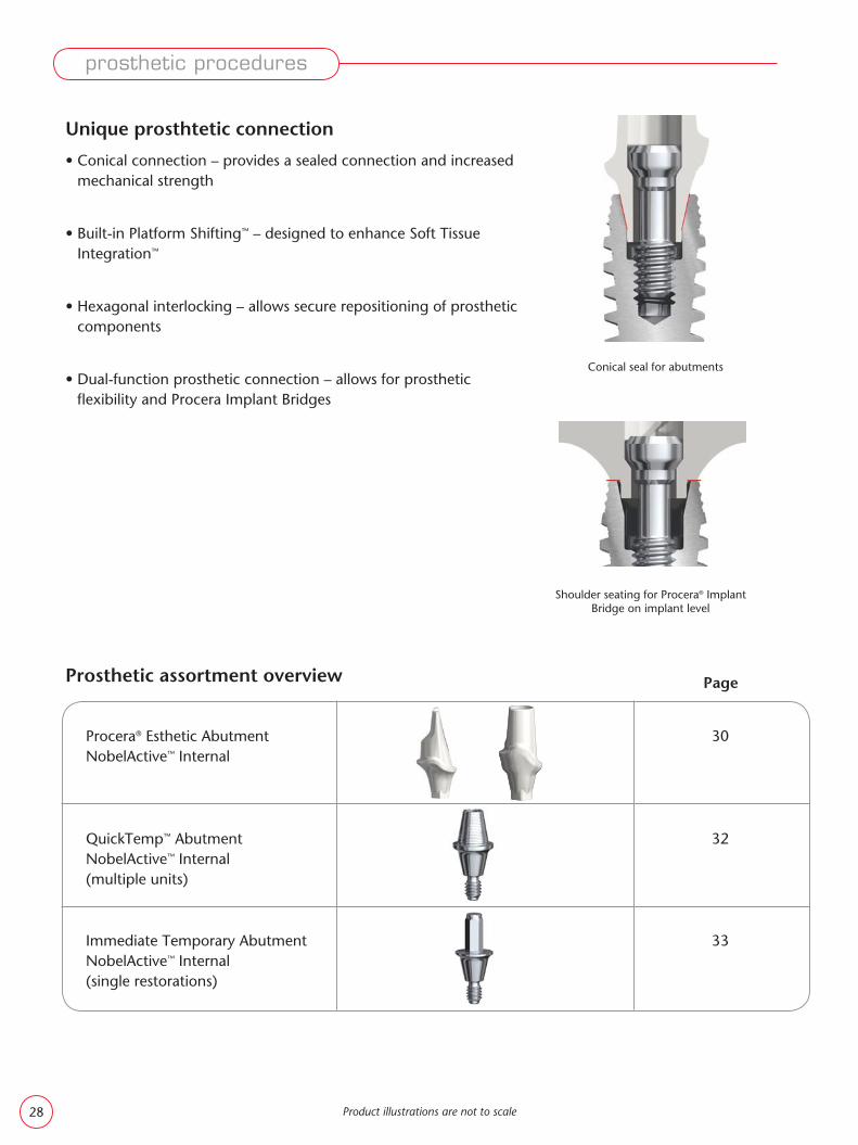
Conical seal for abutments
prosthetic procedures
Unique prosthtetic connection
• Conical connection – provides a sealed connection and increased mechanical strength
• Built-in Platform Shifting™ – designed to enhance Soft Tissue Integration™
• Hexagonal interlocking – allows secure repositioning of prosthetic components
• Dual-function prosthetic connection – allows for prosthetic fl exibility and Procera Implant Bridges
Prosthetic assortment overview
Shoulder seating for Procera® Implant Bridge on implant level
28

Product illustrations are not to scale
Page
40
42
47
49
50
37Esthetic Abutment NobelActive™ Internal
Snappy Abutment™ NobelActive™ Internal
Multi-unit Abutment NobelActive™ Internal
Procera® Implant Bridge Zirconia
Procera® Implant Bridge Titanium
Screw Ceramic Abutment Brånemark System® NP or RP
prosthetic procedures
34Procera® Abutment ZirconiaNobelActive™ InternalProcera® Abutment TitaniumNobelActive™ Internal
38Narrow Profi le Abutment NobelActive™ Internal
NP RP
29

NP RP
2.
3.
1.
• Remove the abutment and place it into the corresponding Protection Analog. Mount and tighten the Handle for Protection Analog (1).
Note! For strength and fi t reasons, never modify the area of the abutments marked in red (2). Do not modify the abutments below the dimensions shown. These are the minimum default dimen-sions of the Procera® Manufacturing System.
• Modify extra-orally, using a high-speed tur-bine with copious water irrigation and dia-mond drills (3)
• Measure the height of the soft tissue and select the correct abutment according to the illustra-tion chart
• Place the clean and sterilized abutment on the implant. Slightly tighten the abutment screw using the Screwdriver Manual Unigrip™
• Check the shape and fi t
• Mark any area in need of modifi cation
• Only for use in anterior region
Zirconia
Indications• Single tooth or multiple unit anterior implant restorations• Cement-retained restoration
Product illustrations are not to scale
Immediate Function™ – Procera® Esthetic Abutment NobelActive™ Internal
1. Abutment try-in
2. Modifi cation
prosthetic procedures
30
prosthetic procedures
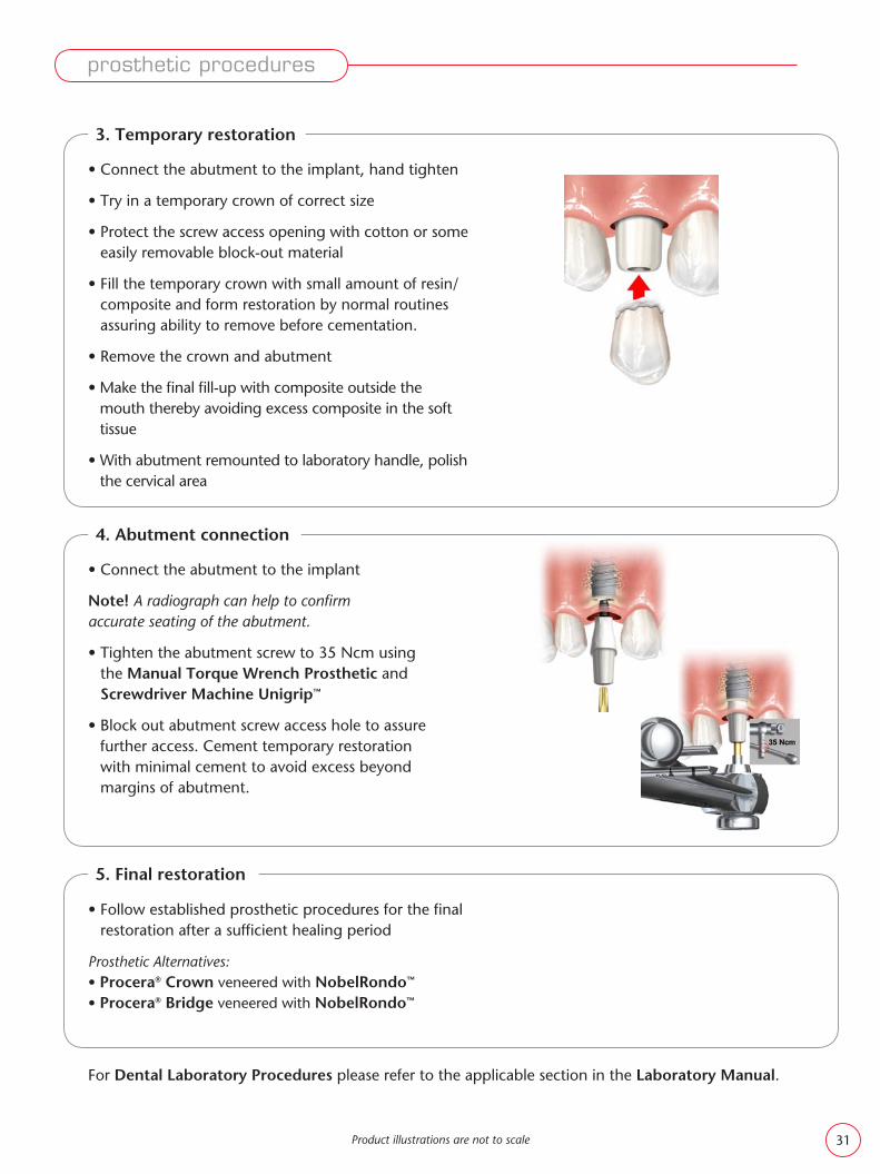
• Connect the abutment to the implant
Note! A radiograph can help to confi rm accurate seating of the abutment.
• Tighten the abutment screw to 35 Ncm using the Manual Torque Wrench Prosthetic and Screwdriver Machine Unigrip™
• Block out abutment screw access hole to assure further access. Cement temporary restoration with minimal cement to avoid excess beyond margins of abutment.
• Follow established prosthetic procedures for the fi nal restoration after a suffi cient healing period
Prosthetic Alternatives:• Procera® Crown veneered with NobelRondo™
• Procera® Bridge veneered with NobelRondo™
Product illustrations are not to scale
For Dental Laboratory Procedures please refer to the applicable section in the Laboratory Manual.
• Connect the abutment to the implant, hand tighten
• Try in a temporary crown of correct size
• Protect the screw access opening with cotton or some easily removable block-out material
• Fill the temporary crown with small amount of resin/composite and form restoration by normal routines assuring ability to remove before cementation.
• Remove the crown and abutment
• Make the fi nal fi ll-up with composite outside the mouth thereby avoiding excess composite in the soft tissue
• With abutment remounted to laboratory handle, polish the cervical area
3. Temporary restoration
4. Abutment connection
5. Final restoration
31
Product illustrations are not to scale
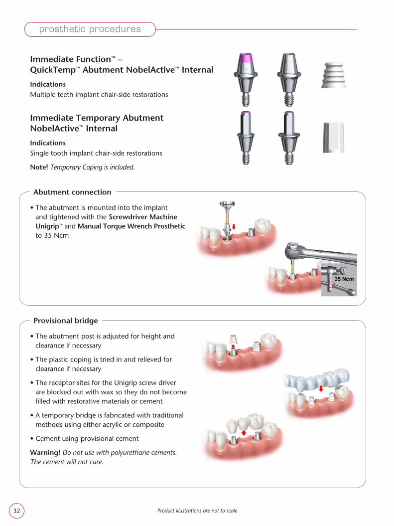
Immediate Function™ – QuickTemp™ Abutment NobelActive™ Internal
IndicationsMultiple teeth implant chair-side restorations
• The abutment is mounted into the implant and tightened with the Screwdriver Machine Unigrip™ and Manual Torque Wrench Prosthetic to 35 Ncm
Abutment connection
Immediate Temporary Abutment NobelActive™ Internal
IndicationsSingle tooth implant chair-side restorations
Note! Temporary Coping is included.
• The abutment post is adjusted for height and clearance if necessary
• The plastic coping is tried in and relieved for clearance if necessary
• The receptor sites for the Unigrip screw driver are blocked out with wax so they do not become fi lled with restorative materials or cement
• A temporary bridge is fabricated with traditional methods using either acrylic or composite
• Cement using provisional cement
Warning! Do not use with polyurethane cements. The cement will not cure.
Provisional bridge
prosthetic procedures
32
Product illustrations are not to scale
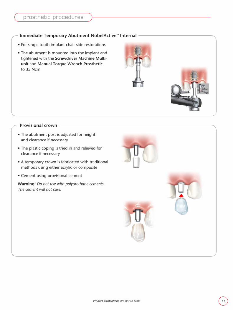
• The abutment post is adjusted for height and clearance if necessary
• The plastic coping is tried in and relieved for clearance if necessary
• A temporary crown is fabricated with traditional methods using either acrylic or composite
• Cement using provisional cement
Warning! Do not use with polyurethane cements. The cement will not cure.
Provisional crown
• For single tooth implant chair-side restorations
• The abutment is mounted into the implant and tightened with the Screwdriver Machine Multi-unit and Manual Torque Wrench Prosthetic to 35 Ncm
Immediate Temporary Abutment NobelActive™ Internal
prosthetic procedures
33

Product illustrations are not to scale
prosthetic procedures
Procera® Abutment NobelActive™ Internal
Zirconia, Titanium
These abutments are designed and ordered in Procera® Software
Indications • Single tooth or multiple implant restorations• Cement-retained
Note! Procera® Abutment Zirconia NobelActive™ Internal is only for use in anterior region.
• Place the impression coping into the implant and take an implant level impression
• The healing abutment or temporary restoration is replaced in the patient’s mouth
• Opposing jaw information and shade are includ-ed with the impression and impression coping when sent to the dental laboratory
• The dental technician designs the Procera® Abutment. When the design is completed, data is transferred to the Procera® production facility via the Internet.
• The abutment is produced and returned to the laboratory
• In the laboratory the abutment is scanned for a Procera® Crown or Procera® Bridge, which after production, will be veneered with NobelRondo™
1. Impression
2. Laboratory procedures
34

NP RP
Product illustrations are not to scale
Note! For strength and fi t reasons, never modify the area of the ceramic abutments marked in red. Do not modify the abutments below the dimensions shown. These are the minimum default dimensions of the Procera® Manufacturing System.
• Ensure that the implant platform is free from any soft-tissue or bone remnants
• Position the abutment/screw assembly into the implant and secure the screw in the implant using the Screwdriver Unigrip™
• A radiograph can be helpful to confi rm accurate seating of the abutment
• Tighten the abutment screw to 35 Ncm using the Manual Torque Wrench Prosthetic and Screwdriver Machine Unigrip™
Note! Removal of the tightened abutment, afterloosening of the abutment screw, necessitates aclamp to slightly jiggle and remove the abutment.
• Gently seat the restoration on the abutment and check both the occlusion and the interproximal contacts. The restoration should be in light occlusion. Excursive contact should be minimal.
• Fill the screw access channel with a block-out material to preserve abutment screw access
• Cement the restoration using permanent cement
prosthetic procedures
3. Abutment connection
4. Cementation of fi nal restoration
35

NP RP
NP RP
NP RP
NP RP
RP
RP
Product list for clinical procedures
Procera® Abutment Includes:Abutment Screw
Impression Coping Implant Level Closed TrayAlternatives for internal connection:
• Narrow Platform ∅ 3.6 and ∅ 5mm• Regular Platform ∅ 3.6, ∅ 5 and 6mm
Impression Coping Implant Level Open Tray
• Narrow Platform ∅ 3.6 and ∅ 5mm• Regular Platform ∅ 3.6, ∅ 5 and 6mm
Implant Replica
For Dental Laboratory Procedures please refer to the applicable section in the Laboratory Manual.
Internal connection
Product illustrations are not to scale
prosthetic procedures
36

• Position the abutment/screw assembly into the implant and tighten the screw until resistance is felt using the Screwdriver Unigrip™
• A radiograph can help to confi rm accurate seating of the abutment to the implant
• Modifi cations – if needed: Remove the abut-ment, place it in a Proctection Analog and Handle, and modify it with a carborundum disk and carbide bur. If the modifi cation is made intra-orally, use profuse water irrigation.
• Tighten the abutment screw to 35 Ncm using the Manual Torque Wrench Prosthetic and Screwdriver Machine Unigrip™
Note! Removal of the tightened abutment, afterloosening of the abutment screw, necessitates aclamp to slightly jiggle and remove the abutment.
• Block out abutment screw channels
• Take a standard C&B impression
• Send the impression to the dental laboratory
Esthetic Abutment NobelActive™ Internal
Titanium
Indications• Single tooth or multiple unit implant restorations• Cement-retained restorations
The abutment is designed with a scalloped margin that profi les natural soft tissue contours with various collar heights available based on the implant platform.
1. Abutment connection
2. Impression
Product illustrations are not to scale
prosthetic procedures
37

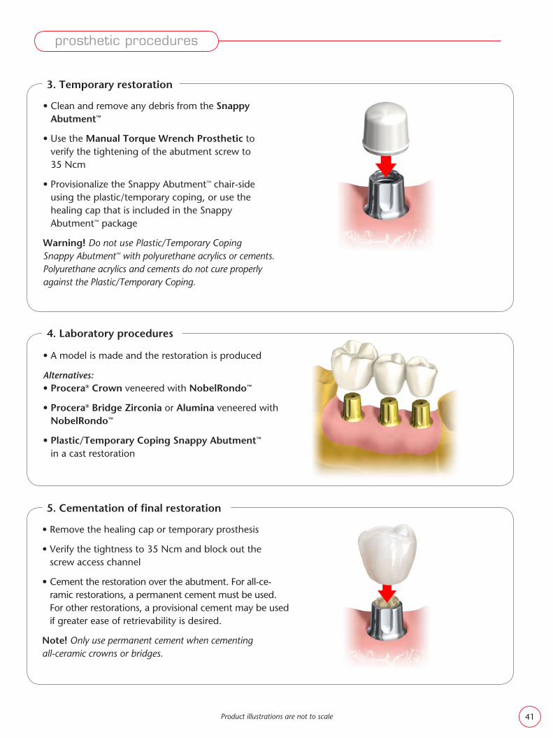
• Clean and remove any debris from the Esthetic Abutment
• Provisionalize the Esthetic Abutment by normal crown and bridge routines
• Verify the tightness to 35 Ncm and block out the screw access channel
• Gently seat the restoration on the abutment and check both the occlusion and the interproximal contacts. The restoration should be in light occlusion. Excursive contact should be minimal.
• Cement the restoration using provisional or permanent cement
Note! Only use permanent cement when cementing all-ceramic crowns or bridges.
3. Temporary restoration
4. Laboratory procedures
5. Cementation of fi nal restoration
In the laboratory, a model is made and a restoration is produced.
Alternatives:• Procera® Crown veneered with NobelRondo™
• Procera® Bridge veneered with NobelRondo™
• For temporary restorations
• For implant restorations with limited interdental space
• Take an implant level impression
Laboratory Procedures
• A model is made, the abutment is modifi ed, if needed, and a restoration is made
• Follow the prescribed procedures for modifi cation, connection and cementation
Note! Removal of the tightened abutment, after loosening of the abutment screw, necessitates a clamp to slightly jiggle and remove the abutment.
Narrow Profi le Abutment NobelActive™ Internal
Product illustrations are not to scale
prosthetic procedures
38

NP RP
NP RP
NP RP RP
NP RP RP
NP RP
NP RP
Product list for clinical procedures
Esthetic Abutment Includes:Abutment Screw
Impression Coping Implant Level Closed Tray
• Narrow Platform ∅ 3.6 and ∅ 5mm• Regular Platform ∅ 3.6, ∅ 5 and 6mm
Impression Coping Implant Level Open Tray
• Narrow Platform ∅ 3.6 and ∅ 5mm• Regular Platform ∅ 3.6, ∅ 5 and 6mm
Implant Replica
For Dental Laboratory Procedures please refer to the applicable section in the Laboratory Manual.
Esthetic Abutment 15°Includes:Abutment Screw
Internal connection
Product illustrations are not to scale
prosthetic procedures
Narrow profi le Abutment NobelActive™ Internal
• Narrow Platform length 7 and 9mm• Regular Platform length 7 and 9mm
39

• Press the impression coping onto the abutment. A “snap” will indicate that the impression coping is fully engaged and well adapted to the margin of the abutment.
• Take a standard impression. When the impression is pulled, the impression coping will disengage from the Snappy Abutment™ and is picked up in the impression.
• Send the impression with traditional opposing arch, occlusal registration and shade information to the dental laboratory for model and prosthetic fabrication
Product illustrations are not to scale
Snappy Abutment™ NobelActive™ Internal RP
Titanium
Indications• Single tooth or multiple unit implant restorations,
ideal for posterior restorations• Cement-retained restorations
• Position the abutment/screw assembly into the implant and secure the screw until resistance is felt using the Screwdriver Unigrip™
• A radiograph can help to confi rm accurate seating of the abutment to the implant
• Tighten the abutment screw to 35 Ncm using the Manual Torque Wrench Prosthetic and Screwdriver Machine Unigrip™
Note! Removal of the tightened abutment, afterloosening of the abutment screw, necessitates aclamp to slightly jiggle and remove the abutment.
1. Abutment connection
2. Impression
prosthetic procedures
40
Product illustrations are not to scale
• Clean and remove any debris from the Snappy Abutment™
• Use the Manual Torque Wrench Prosthetic to verify the tightening of the abutment screw to 35 Ncm
• Provisionalize the Snappy Abutment™ chair-side using the plastic/temporary coping, or use the healing cap that is included in the Snappy Abutment™ package
Warning! Do not use Plastic/Temporary Coping Snappy Abutment™ with polyurethane acrylics or cements. Polyurethane acrylics and cements do not cure properly against the Plastic/Temporary Coping.
• Remove the healing cap or temporary prosthesis
• Verify the tightness to 35 Ncm and block out the screw access channel
• Cement the restoration over the abutment. For all-ce-ramic restorations, a permanent cement must be used. For other restorations, a provisional cement may be used if greater ease of retrievability is desired.
Note! Only use permanent cement when cementing all-ceramic crowns or bridges.
• A model is made and the restoration is produced
Alternatives:• Procera® Crown veneered with NobelRondo™
• Procera® Bridge Zirconia or Alumina veneered with NobelRondo™
• Plastic/Temporary Coping Snappy Abutment™ in a cast restoration
3. Temporary restoration
4. Laboratory procedures
5. Cementation of fi nal restoration
prosthetic procedures
41

Product list for clinical procedures
Snappy Abutment™
Includes:Abutment ScrewHealing CapImpression Coping
Impression Coping Snappy Abutment™
Abutment Replica Snappy Abutment™
Healing Cap Snappy Abutment™
Plastic/Temporary Coping Snappy Abutment™ Engaging/Non-Engaging
Internal connection
Product illustrations are not to scale
Abutment collar height
Abutment collar height
Multi-unit Abutment NobelActive™ Internal
Titanium
Indications• Multiple unit screw-retained restorations • May be used in combination with an implant level framework design if not all implants
benefi t from abutments• Used to elevate seating platform of restoration when restoration to implant level
not practical or indicated due to depth or angle of implant
prosthetic procedures
42

• The abutment is placed over the implant by using the premounted abutment holder. Please note that there are several possible positions in which to place the abutment.
• Tighten the abutment screw using a Screwdriver Unigrip™ until resistance is felt
Note! Caution needs to be taken when starting to insert the screw. It is important that correct seating is made.
• A radiograph can help to confi rm accurate seating of the abutment
• The holder is then unscrewed from the abutment by turning it counter-clockwise
• Tighten the abutment screw to 15 Ncm only using the Manual Torque Wrench Prosthetic and Screwdriver Machine Unigrip™
Note! Be sure not to exceed 15 Ncm for Multi-unit Angulated Abutment screw.
Note! Removal of the tightened abutment, after loosening of the abutment screw, necessitates a clamp to slightly jiggle and remove the abutment.
• Selection of proper abutment height: measure the abutment collar height
• Use the premounted plastic holder to place the abutment into the implant and screw the abutment into the correct position
• If necessary, shorten the holder with a pair of scissors
• When the abutment is seated, the plastic holder should be removed with a slight bending movement
• A radiograph can be helpful to confi rm accurate seating of the abutment
• Tighten the abutment screw to 35 Ncm using the Manual Torque Wrench Prosthetic and Screwdriver Machine Multi-unit
1a. Abutment connection straight Multi-unit Abutment
1b. Abutment connection 17° and 30° Multi-unit Abutment
Product illustrations are not to scale
prosthetic procedures
43

• Connect the impression coping to the abutment
• Inject impression material and record the impression
• After setting, remove the impression and disconnect the impression copings. Attach the abutment replicas to each coping.
• Place the impression coping abutment replica assembly into its corresponding location in the impression
• Connect the temporary restoration (see chapter Provi-sional Solutions) or healing cap and send the impression to the dental laboratory.
• Connect the impression coping on the abutment and tighten using the Screwdriver Unigrip™
• Relieve and perforate the impression tray to allow full seating of the tray and protrusion of the guide pins. Verify that there is access to the tops of all guide pins to at least the level of the impression tray opening. If there is a large opening, close it with baseplate wax, with the guide pins indenting or perforating the wax.
• Inject impression material and seat the impression tray fully so that the tips of all the guide pins are identifi ed. After setting, unscrew the guide pins and remove the impression tray.
• Connect the temporary restoration (see chapter Provisional Solutions) or healing cap and send the impression to the dental laboratory
2a. Closed tray – Abutment level impression:
2b. Open tray – Abutment level impression:
Product illustrations are not to scale
prosthetic procedures
44

• In the laboratory, a model is made and a restoration is produced
Alternatives:• Procera® Implant Bridge
• Gold Coping Multi-unit in cast restoration
• Verify abutment screw tightness of 15 Ncm for angled abutments and 35 Ncm for regular Multi-unit abutments.
• Evaluate full seating of the restoration on the model and intra-orally.
• Connect the restoration to the abutments with prosthetic screws. Start with the mid region post and tighten the other screws alternating left and right sides.
• Tighten the prosthetic screws to 15 Ncm using the Manual Torque Wrench Prosthetic and Screwdriver Machine Unigrip™
• Fill the screw access channel with a suitable material such as gutta-percha, silicone or temporary fi lling material
3. Laboratory procedures
4. Connection of fi nal restoration
Product illustrations are not to scale
prosthetic procedures
45

RPRP RP
Product list for clinical procedures
Multi-unit AbutmentAvailable as straight, 17°, 30°Includes:Abutment Screw
Prosthetic Screw Multi-unit for connection of Procera® Implant Bridge
Impression Coping closed tray Multi-unit
Impression Coping open tray Multi-unit
For Dental Laboratory Procedures please refer to the applicable section in the Laboratory Manual.
Abutment Replica Multi-unit
Healing Cap Available as regular/wide
Internal connection
Product illustrations are not to scale
prosthetic procedures
46

Procera® Implant Bridge ZirconiaIndications• Implant level only• Multiple unit restorations• Indicated for all positions in the mouth• Screw-retained• Up to 14 units• Requires a minimum of 4 × 2.5mm connector between
units (Height x Width) and a minimum cross-sectional area of 8mm2
Contraindications• Cases where the mesial/distal cantilevers have a length of more than one unit• There should be no more than two pontics between the supporting implants• Bruxism
Note! If an implant level Procera® Implant Bridge is planned to be connected to the implant, a Healing Abutment Bridge NobelActive™ Internal, should be used. For impression use Impression Coping Bridge Open Tray NobelActive™ Internal
• The screws used are: Screw Ceramic Abutment Brånemark System® NP or RP
• Place impression copings onto the implants. Take an impression to transfer the position of the implants to a working model.
• Connect the temporary restoration or healing abutments
• Attach the appropriate implant replicas to the impression copings and send the impression to the laboratory
• A model and a framework are produced and scanned using the Procera® Forte Scanner. The data is transferred to a Procera® production facility.
• The framework is milled from a presintered piece of zirconia, sintered to full density and returned to the laboratory
• The restoration is completed using NobelRondo™ Zirconia veneering dental ceramic
1. Impression
2. Laboratory procedures
Product illustrations are not to scale
prosthetic procedures
47

RP
NP RP
NP RP
NP
NP RP
Screw Ceramic Abutment Brånemark System® NP or RP
Impression Coping Bridge open tray NobelActive™ Internal• Narrow Platform • Regular Platform
Product list for clinical procedures
Procera® Implant Bridge – at Implant Level Does not include Abutment Screws
• Ensure that the implants are free from any soft tissue or bone remnants
• Evaluate full seating of the restoration on the model and intra-orally
• Connect the restoration to the implants with abutment screws
• The Abutment Screws for NobelActive™ Internal are Screw Ceramic Abutment Brånemark System® NP or RP
Note! Abutment screws are not included.
• A radiograph may help to verify correct seating of the restoration
• Tighten the abutment screws to 35 Ncm using the Manual Torque Wrench Prosthetic and Screwdriver Machine Unigrip™
• Fill the screw access channel with a suitable material such as gutta-percha, silicone or temporary fi lling material
3. Connection of fi nal restoration
Healing Abutment Bridge NobelActive™ Internal• Narrow Platform • Regular Platform
Internal connection
Implant Replica
Product illustrations are not to scale
prosthetic procedures
48

Procera® Implant Bridge TitaniumIndications• Implant or abutment level• Multiple unit restorations• Screw-retained
The screws used are: Screw Ceramic Abutment Brånemark System® NP or RP
• Place impression copings onto the implants and take an implant level impression
• Connect the temporary restoration or healing abutment and send the impression to the laboratory
Note! If an implant level Procera® Implant Bridge is planned to be connected to the implant, a Healing Abutment Bridge NobelActive™ Internal, should be used. For impression use Impression Coping Bridge Open Tray NobelActive™ Internal.
• Place the Impression Coping Multi-unit onto the Multi-unit Abutments
• Connect the temporary restoration (see the chapter: Provisional Solutions) or healing cap and send the impression to the laboratory
1a. Impression implant level
1b. Impression abutment level
• A model is made and a resin framework is produced and sent to a Procera® production facility or scanned by using the Procera® Forte scanner
• The framework is milled from a solid piece of titanium and returned to the laboratory
• The restoration is completed using conventional methods
2. Laboratory procedures
Product illustrations are not to scale
prosthetic procedures
49

Product illustrations are not to scale
• Ensure that the implants are free from any soft tissue or bone remnants
• Evaluate full seating of the restoration on the model and intra-orally
• Connect the restoration to the implants with abutment screws using the Screwdriver Unigrip™. Start with the mid region post and tighten the following screws alternating left and right sides.
• The Abutment Screws for NobelActive™ Internal are Screw Ceramic Abutment Brånemark System® NP or RP
• A radiograph can help confi rm accurate seating
• Tighten the abutment screws to 35 Ncm using the Manual Torque Wrench Prosthetic and Screwdriver Machine Unigrip™
• Fill the screw access channel with a suitable material such as gutta-percha, silicone or temporary fi lling material
3a. Connection of fi nal restoration at implant level
• Connect the restoration to the abutments with prosthetic screws. Start with the mid region post and tighten the other screws alternating left and right sides.
• Tighten the prosthetic screws to 15 Ncm using the Manual Torque Wrench Prosthetic and Screwdriver Machine Unigrip™
• Fill the screw access channel with a suitable material such as gutta percha, silicone or temporary fi lling material
3b. Connection of fi nal restoration at abutment level
prosthetic procedures
50

RP RPRP
NP RP
NP RP
NP RP
NP RP
Abutment level components
Multi-unit AbutmentAvailable as straight, 17°, 30°Includes:Abutment Screw
Prosthetic Screw Multi-unit
Impression Coping closed tray Multi-unit
Impression Coping open tray Multi-unit
Abutment Replica Multi-unit
Healing Cap Multi-unit Available as regular/wide
Product list for clinical procedures
Procera® Implant Bridge – at Implant or Abutment Level does not include Abutment Screws/Prosthetic Screws
Implant level components
Screw Ceramic Abutment Brånemark System® NP or RP
Impression Coping Bridge open tray NobelActive™ Internal
• Narrow Platform • Regular Platform
Healing Abutment Bridge NobelActive™ Internal
• Narrow Platform • Regular Platform
Implant Replica
Internal connection
Product illustrations are not to scale
prosthetic procedures
51

29149
32112
34143
3458432948
29164
34141
34988
34142 34144
32112
32297*
32261*
34638*
32264*
32276*
34582*
* Article not included in this kit and also available in other lengths
NobelActive™ Surgery Kit 34987(The articles below can also be purchased separately)
Also included in kit:
NobelActive™ Radiographic Template 34989
NobelActive™ Wall Chart 21297
Implant/Prosthetic Organizer 29532
Implant Sleeve Holder 29543
Appendix I – Kits
Product illustrations are not to scale
appendices
52

Prosthetic Kit 32309Kit includes:
(The articles below can also be purchased separately)
Prosthetic Kit Box (without instrumentation) 32322
Manual Torque Wrench Prosthetic 29165
Screwdriver Machine Unigrip™ 20mm 29151
Screwdriver Machine Unigrip™ 30mm 29153
Screwdriver Machine Multi-unit 21mm 29158
Procera® Esthetic Abutment NobelActive™ Internal Selection Kit 34184Kit includes:
Procera® Esthetic Abutment NobelActive™ Kit Box 34185
Protection Analog NP
Protection Analog RP
Handle for Protection Analogs 29122
Screwdriver Manual UniGrip™ 36mm 29150
Illustration Chart Procera® Esth Abut NobelActive™ Int 18266
Procera® Abutment Wax-up Kit NobelActive™ 34991Kit includes:
Wax-up Replica NobelActive™ Internal NP
Wax-up Replica NobelActive™ Internal RP
Procera® Abutment 3D CADD Kit NobelActive™ 34992 Kit includes:
T-bar NobelActive™ Internal NP
Guide Pin Fixture Level NobelActive™ Internal NP
T-bar NobelActive™ Internal RP
Guide Pin Fixture Level NobelActive™ Internal RP
Appendix I – Kits
Product illustrations are not to scale
appendices
53

➄
➃
➂
➁➀➇
➅
➆
Appendix II – NobelActive™ Manual Torque Wrench
Instructions for use – Surgical application
Intended for tightening or position adjustment of implants.
Fig. 1, 2. Insert the implant driver.
Fig. 3. For correct handling and tightening torque, see the manual for the applicable product. The maximum tightening torque, 70 Ncm, is indicated by the line on the scale.
Fig. 4. Warning: The use of the wrench body instead of the level arm may result in excessive torque being transferred to the implant site. This may cause over-compression of the bone, leading to bone resorption.
Fig. 5, 6. If necessary, the implant can be backed out using the wrench with the direc tion indicator arrow pointing counter-clockwise.
Fig. 8. Clean the parts thoroughly. Allow them to dry completely. Sterilize the instrument using a steam autoclave at 135 °C for minimum hold time of 5 minutes or according to recommendations from the manufacturer of the autoclave.
Product illustrations are not to scale
appendices
54
*
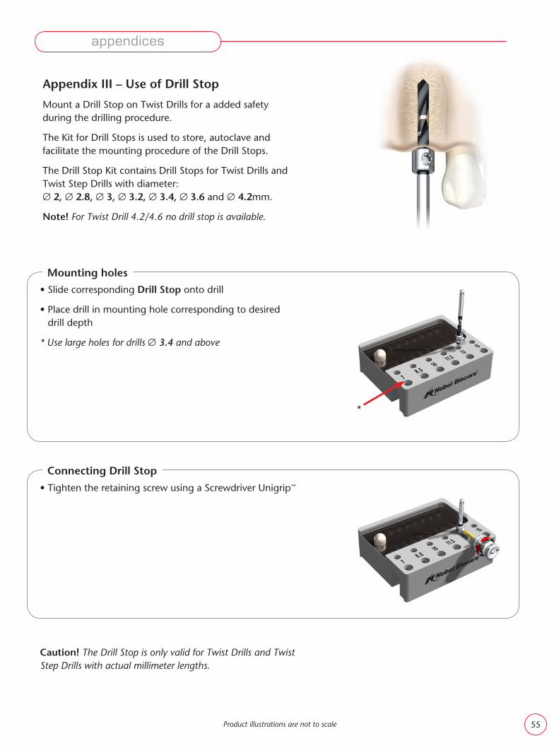
Appendix III – Use of Drill Stop
Mount a Drill Stop on Twist Drills for a added safety during the drilling procedure.
The Kit for Drill Stops is used to store, autoclave and facilitate the mounting procedure of the Drill Stops.
The Drill Stop Kit contains Drill Stops for Twist Drills and Twist Step Drills with diameter: ∅ 2, ∅ 2.8, ∅ 3, ∅ 3.2, ∅ 3.4, ∅ 3.6 and ∅ 4.2mm.
Note! For Twist Drill 4.2/4.6 no drill stop is available.
• Slide corresponding Drill Stop onto drill
• Place drill in mounting hole corresponding to desired drill depth
* Use large holes for drills ∅ 3.4 and above
Mounting holes
• Tighten the retaining screw using a Screwdriver Unigrip™
Caution! The Drill Stop is only valid for Twist Drills and Twist Step Drills with actual millimeter lengths.
Connecting Drill Stop
Product illustrations are not to scale
appendices
55

appendices
Appendix IV – Cleaning and sterilization
Disposable Drills
• All Drills are disposable and should be used for one surgery only. Do not re-sterilize disposable drills.
Instruments
• Devices must be cleaned and sterilized before intraoral use in accordance with established procedures at the hospital/clinic
Principal cleaning and sterilization procedure
• Clean and disinfect instruments and drills in a dishwasher. Alternatively: Disinfect, clean by hand and put in an ultra-sonic cleaner.
• Dry instruments and place them in sterilization packets
• Sterilize instruments using a steam autoclave (according to autoclave manufacturer recommendations)
Cleaning contra-angle
• The contra-angle must be cleaned carefully immediately after operation
• First clean in a washer or under running water. The head should be separated from the shank and both parts carefully lubricated.
Another alternative is to clean and lubricate the contra-angle in an automatic unit (for contra-angles).
• Place the disassembled contra-angle in double peel-open bag or in tray and sterilize in autoclave
Modifi ed abutment and restoration
• If indicated, clean and sterilize modifi ed abutments and restorations from the dental laboratory according to com-monly accepted procedures for dental laboratory work
Manual Torque Wrench
Clean parts thoroughly. Allow them to dry completely.
Abutment sterilization
• Abutments that require sterilization, should be sterilized prior to use, with steam sterilization at 135 °C for 5 minutes
Product illustrations are not to scale56

appendices
RPNP
RP
#9 #10
#11 #12
34178 34179
3417734176
34123
34124 34175
#5 #6
#7 #8
#1 #2
#3 #4
34118 34119
3412134120
2.7
mm
mm
mm
mm
mm
mm
mm
mm
mm
mm
mm
mm
1.5 7.5
4.6
2.7 1.5
1.5
8.5
8.5
2.7 1.5 8.5
5
3.7 2.5 8.5
4.6
3.7 2.5 8.5
4.6
2.7 1.5 7.5
4.6
2.7
1.5 8.5 2.7
5
6 6
6 6
5
3.7 2.5 9.5
3.7 2.5 9.5
3.7 2.5 9.5
3.7 2.5 9.5
5
34122
NobelActive™ Internal NP
NobelActive™ Internal RP
Procera® Esthetic Abutment NobelActive™ Internal
If modifi cation of the abutment is needed see page 30.
ang
led
stra
igh
tan
gle
dst
raig
ht
low high
low high low high
57

REG
ULA
RN
AR
RO
W
Drills Drill Stop
Twist Drills
∅ 2, 7–15mm 32297∅ 2,10–18mm 32299
Twist Drills
∅ 2, 7–15mm 32297∅ 2,10–18mm 32299
Twist Step Drills
∅ 2.4/2.8, 7–15mm 32261∅ 2.4/2.8, 10–18mm 32262∅ 2.8/3.2, 7–15mm 34638∅ 2.8/3.2, 10–18mm 34639
TiUnite®
NobelActive™ Internal NP 3.5 × 10mm 34125NobelActive™ Internal NP 3.5 × 11.5mm 34126NobelActive™ Internal NP 3.5 × 13mm 34127NobelActive™ Internal NP 3.5 × 15mm 34128
cover screws not included
NobelActive™ Internal NP
Platform diameter 3.5Implant diameter 3.5Abutment interface diameter 3.0
NobelActive™ Internal RP
Platform diameter 3.9Implant diameter 4.3Abutment interface diameter 3.4
TiUnite®
NobelActive™ Internal RP 4.3 × 10mm 34131NobelActive™ Internal RP 4.3 × 11.5mm 34132NobelActive™ Internal RP 4.3 × 13mm 34133NobelActive™ Internal RP 4.3 × 15mm 34134
Platform diameter 3.9Implant diameter 5.0Abutment interface diameter 3.4
TiUnite®
NobelActive™ Internal RP 5.0 × 10mm 34137NobelActive™ Internal RP 5.0 × 11.5mm 34138NobelActive™ Internal RP 5.0 × 13mm 34139NobelActive™ Internal RP 5.0 × 15mm 34140
cover screws not included
Drill Stop
∅ 2mm 33063∅ 2.4/2.8mm 33064∅ 2.8/3.2mm 33077
Twist Step Drills
∅ 2.4/2.8, 7–15mm 32261∅ 2.4/2.8, 10–18mm 32262∅ 2.8/3.2, 7–15mm 34638∅ 2.8/3.2, 10–18mm 34639∅ 3.2/3.6, 7–15mm 32264∅ 3.2/3.6, 10–18mm 32265∅ 3.8/4.2, 7–15mm 32276∅ 3.8/4.2, 10–18mm 32277
Twist Drills
∅ 2, 7–15mm 32297∅ 2,10–18mm 32299
Twist Step Drills
∅ 2.4/2.8, 7–15mm 32261∅ 2.4/2.8, 10–18mm 32262∅ 3.2/3.6, 7–15mm 32264∅ 3.2/3.6, 10–18mm 32265∅ 3.8/4.2, 7–15mm 32276∅ 3.8/4.2, 10–18mm 32277∅ 4.2/4.6, 7–15mm 34582∅ 4.2/4.6, 10–18mm 34583
Drill Stop
∅ 2mm 33063∅ 2.4/2.8mm 33064∅ 2.8/3.2mm 33077∅ 3.2/3.6mm 33084∅ 3.8/4.2mm 33081
Drill Stop
∅ 2mm 33063∅ 2.4/2.8mm 33064∅ 3.2/3.6mm 33084∅ 3.8/4.2mm 33081
Surgical components overview NobelActive™
Implants
Product illustrations are not to scale
product catalog
58
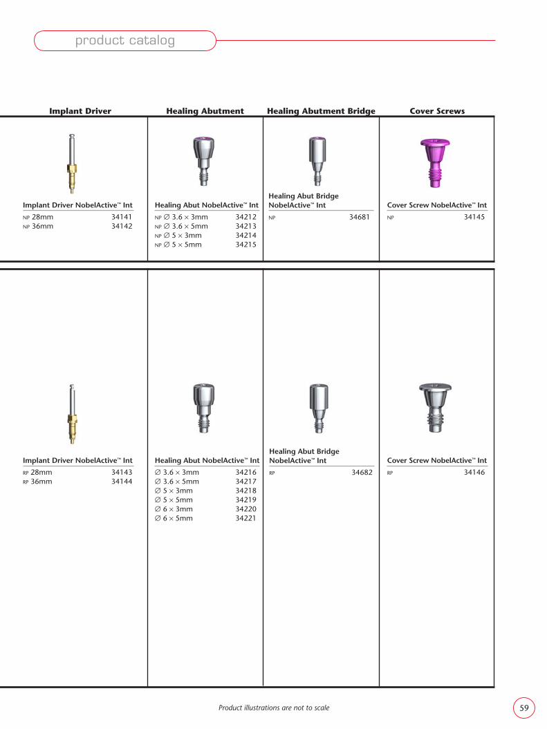
Implant Driver NobelActive™ Int
NP 28mm 34141NP 36mm 34142
Healing Abut NobelActive™ Int
NP ∅ 3.6 × 3mm 34212NP ∅ 3.6 × 5mm 34213NP ∅ 5 × 3mm 34214NP ∅ 5 × 5mm 34215
Healing Abut Bridge NobelActive™ Int
NP 34681
Healing Abut Bridge NobelActive™ Int
RP 34682
Cover Screw NobelActive™ Int
NP 34145
Implant Driver NobelActive™ Int
RP 28mm 34143RP 36mm 34144
Healing Abut NobelActive™ Int
∅ 3.6 × 3mm 34216∅ 3.6 × 5mm 34217∅ 5 × 3mm 34218∅ 5 × 5mm 34219∅ 6 × 3mm 34220∅ 6 × 5mm 34221
Cover Screw NobelActive™ Int
RP 34146
Healing Abutment Bridge Cover ScrewsImplant Driver Healing Abutment
Product illustrations are not to scale
product catalog
59

Product specifi cations NobelActive™
NP implantNobelActive™ Internal NP 3.5 × 10mm 34125
NobelActive™ Internal NP 3.5 × 11.5mm 34126
NobelActive™ Internal NP 3.5 × 13mm 34127
NobelActive™ Internal NP 3.5 × 15mm 34128
RP 4.3 implantNobelActive™ Internal RP 4.3 × 10mm 34131
NobelActive™ Internal RP 4.3 × 11.5mm 34132
NobelActive™ Internal RP 4.3 × 13mm 34133
NobelActive™ Internal RP 4.3 × 15mm 34134
RP 5.0 implantNobelActive™ Internal RP 5.0 × 10mm 34137
NobelActive™ Internal RP 5.0 × 11.5mm 34138
NobelActive™ Internal RP 5.0 × 13mm 34139
NobelActive™ Internal RP 5.0 × 15mm 34140
Twist DrillsTwist Drill ∅ 2, 7–15mm 32297
Twist Drill ∅ 2,10–18mm 32299
Twist Step DrillsTwist Step Drill ∅ 2.4/2.8, 7–15mm 32261
Twist Step Drill ∅ 2.4/2.8, 10–18mm 32262
Twist Step Drill ∅ 2.8/3.2, 7–15mm 34638
Twist Step Drill ∅ 2.8/3.2, 10–18mm 34639
Twist Step Drill ∅ 3.2/3.6, 7–15mm 32264
Twist Step Drill ∅ 3.2/3.6, 10–18mm 32265
Twist Step Drill ∅ 3.8/4.2, 7–15mm 32276
Twist Step Drill ∅ 3.8/4.2, 10–18mm 32277
Twist Step Drill ∅ 4.2/4.6, 7–15mm 34582
Twist Step Drill ∅ 4.2/4.6, 10–18mm 34583
Drill StopDrill Stop Kit 32430
Drill Stop ∅ 2 33063
Drill Stop ∅ 2.4/2.8 33064
Drill Stop ∅ 2.8/3.2 33077
Drill Stop ∅ 3.2/3.6 33084
Drill Stop ∅ 3.8/4.2 33081
Implant DriversImplant Driver NobelActive™ Int NP 28mm 34141
Implant Driver NobelActive™ Int NP 36mm 34142
Implant Driver NobelActive™ Int RP 28mm 34143
Implant Driver NobelActive™ Int RP 36mm 34144
NobelActive™ Man Torque Wrench Surgical 34584
Surgical Driver 32180
Bone millsBone Mill w Guide NobelActive™ Int NP 34777
Bone Mill Guide NobelActive™ Internal NP 34778
Bone Mill w Guide NobelActive™ Int RP 34779
Bone Mill Guide NobelActive™ Internal RP 34780
Cover Screws Cover Screw NobelActive™ Internal NP 34145
Cover Screw NobelActive™ Internal RP 34146
Healing abutmentsHealing Abut NobelActive™ Int NP ∅ 3.6 × 3mm 34212
Healing Abut NobelActive™ Int NP ∅ 3.6 × 5mm 34213
Healing Abut NobelActive™ Int NP ∅ 5 × 3mm 34214
Healing Abut NobelActive™ Int NP ∅ 5 × 5mm 34215
Healing Abut NobelActive™ Int RP ∅ 3.6 × 3mm 34216
Healing Abut NobelActive™ Int RP ∅ 3.6 × 5mm 34217
Healing Abut NobelActive™ Int RP ∅ 5 × 3mm 34218
Healing Abut NobelActive™ Int RP ∅ 5 × 5mm 34219
Healing Abut NobelActive™ Int RP ∅ 6 × 3mm 34220
Healing Abut NobelActive™ Int RP ∅ 6 × 5mm 34221
Healing Abut Bridge NobelActive™ Int NP 34681
Healing Abut Bridge NobelActive™ Int RP 34682
Impression copings (closed tray)Im Cop Cl Tr NobelActive™ Int NP ∅ 3.6 × 13mm 34230
Im Cop Cl Tr NobelActive™ Int NP ∅ 5 × 13mm 34231
Im Cop Cl Tr NobelActive™ Int RP ∅ 3.6 × 13mm 34232
Im Cop Cl Tr NobelActive™ Int RP ∅ 3.6 × 9mm 34233
Im Cop Cl Tr NobelActive™ Int RP ∅ 5 × 13mm 34234
Im Cop Cl Tr NobelActive™ Int RP ∅ 5 × 9mm 34235
Im Cop Cl Tr NobelActive™ Int RP ∅ 6 × 13mm 34236
Im Cop Cl Tr NobelActive™ Int RP ∅ 6 × 9mm 34237
Impression copings (open tray)Impr Cop Open Tr NobelActive™ Int NP ∅ 3.6 34238
Impr Cop Open Tr NobelActive™ Int NP ∅ 5 34239
Impr Cop Open Tr NobelActive™ Int RP ∅ 3.6 34240
Impr Cop Open Tr NobelActive™ Int RP ∅ 5 34241
Impr Cop Open Tr NobelActive™ Int RP ∅ 6 34242
Impr Cop Bridge Open Tr NobelActive™ Int NP 34679
Impr Cop Bridge Open Tr NobelActive™ Int RP 34680
NP Procera® Esthetic Abutments ZirconiaProcera® Esth Abut NobelActive™ Int NP #1 34118
Procera® Esth Abut NobelActive™ Int NP #2 34119
Procera® Esth Abut NobelActive™ Int NP #3 34120
Procera® Esth Abut NobelActive™ Int NP #4 34121
Product illustrations are not to scale
product catalog
60

Procera® Abutment (to be ordered in Procera® Software)
Procera® Abutment Zr NobelActive™ Int NP
Procera® Abutment Zr NobelActive™ Int RP
Procera® Abutment Ti NobelActive™ Int NP
Procera® Abutment Ti NobelActive™ Int RP
Procera® Wax-up SleeveProcera® W-u Sl Eng NobelActive™ Int NP 34208
Procera® W-u Sl Eng NobelActive™ Int RP 34209
Procera® W-u Sl Non-E NobelActive™ Int NP 34671
Procera® W-u Sl Non-E NobelActive™ Int RP 34672
Temporary abutmentsImmediate Temp Abut NobelActive™ Int NP 34222
Immediate Temp Abut NobelActive™ Int RP 34223
QuickTemp™ Abutment NobelActive™ Int NP 34226
QuickTemp™ Abutment NobelActive™ Int RP 34227
PIB componentsPos Locator Model NobelActive™ Int NP 34673
Pos Locator Model NobelActive™ Int RP 34674
Pos Locator Bridge NobelActive™ Int NP 34676
Pos Locator Bridge NobelActive™ Int RP 34678
Prosthetic screwsScrew Ceramic Abutment Bmk Syst NP 31171
Screw Ceramic Abutment Bmk Syst RP 28815
Laboratory componentsLab Screw Implant Level Bmk Syst NP 31168
Lab Screw Implant Level Bmk Syst RP 5pkg 29290
Guide Pin Implant Level Bmk Syst NP 20mm 31147
Guide Pin Impl Lev Bmk Syst RP 20mm 31148
Guide Pin Impl Lev Bmk Syst RP 30mm 31149
Implant replica NobelActive™ Internal NP 34243
Implant replica NobelActive™ Internal RP 34244
Protect Analog NobelActive™ Int NP 5/pkg 34365
Protect Analog NobelActive™ Int RP 5/pkg 34366
Kits and kit boxesProcera® Est Ab NobelActive™ Int Sel Kit 34184
Procera® E Ab NobelActive™ Int Sel KitBox 34185
NobelActive™ Surgery Kit 34987
NobelActive™ Surgery Kit Box 34988
Procera® Abutment Wax-up Kit NobelActive™ 34991
Procera® Abutment 3D CADD Kit NobelActive™ 34992
NobelActive™ Internal Wall Chart 21297
NobelActive™ Radiographic Template 34989
Ill Chart Procera® Est Ab NobelActive™ Int 18266
RP Procera® Incisor designProcera® Est Abut NobelActive™ Int RP #5 34122
Procera® Est Abut NobelActive™ Int RP #6 34123
Procera® Est Abut NobelActive™ Int RP #7 34124
Procera® Est Abut NobelActive™ Int RP #8 34175
RP Procera® Premolar designProcera® Est Abut NobelActive™ Int RP #9 34176
Procera® Est Abut NobelActive™ Int RP #10 34177
Procera® Est Abut NobelActive™ Int RP #11 34178
Procera® Est Abut NobelActive™ Int RP #12 34179
Multi-unit Abutment NP
Multi-unit Abut NobelActive™ Int NP 1.5mm 34186
Multi-unit Abut NobelActive™ Int NP 2.5mm 34187
Multi-unit Abut NobelActive™ Int NP 3.5mm 34595
17° Multi-u Abut NobelActive™ Int NP 2.5mm 34188
17° Multi-u Abut NobelActive™ Int NP 3.5mm 34189
30° Multi-u Abut NobelActive™ Int NP 3.5mm 34367
30° Multi-u Abut NobelActive™ Int NP 4.5mm 34368
Multi-unit Abutment RP
Multi-unit Abut NobelActive™ Int RP 1.5mm 34190
Multi-unit Abut NobelActive™ Int RP 2.5mm 34191
Multi-unit Abut NobelActive™ Int RP 3.5mm 34596
17° Multi-u Ab NobelActive™ Int RP 2.5mm 34192
17° Multi-u Ab NobelActive™ Int RP 3.5mm 34193
30° Multi-u Ab NobelActive™ Int RP 3.5mm 34369
30° Multi-u Ab NobelActive™ Int RP 4.5mm 34370
For Multi-unit Abutment related prosthetic products, see p. 63
Esthetic abutment NP TitaniumEsthetic Abut NobelActive™ Int NP 1.5mm 34194
Esthetic Abut NobelActive™ Int NP 3mm 34195
15° Esthetic Ab NobelActive™ Int NP 1.5mm 34196
15° Esthetic Ab NobelActive™ Int NP 3mm 34197
Narrow Profi le Ab NobelActive™ Int NP 7mm 34371
Narrow Profi le Ab NobelActive™ Int NP 9mm 34372
Esthetic abutment RP TitaniumEsthetic Abut NobelActive™ Int RP 1.5mm 34198
Esthetic Abutment NobelActive™ Int RP 3mm 34199
15° Esth Abut NobelActive™ Int RP 1.5mm 34200
15° Esth Abutment NobelActive™ Int RP 3mm 34201
Narrow Profi le Ab NobelActive™ Int RP 7mm 34597
Narrow Profi le Ab NobelActive™ Int RP 9mm 34598
Snappy Abutment™ RP
Snappy Abutment™ NobelActive™ Int RP 1.5mm 34206
Snappy Abutment™ NobelActive™ Int RP 3mm 34207
Product illustrations are not to scale
product catalog
61

Index in alphabetical order
Cover Screws Cover Screw NobelActive™ Internal NP 34145Cover Screw NobelActive™ Internal RP 34146
Drill StopDrill Stop ∅ 2 33063Drill Stop ∅ 2.4/2.8 33064Drill Stop ∅ 2.8/3.2 33077Drill Stop ∅ 3.2/3.6 33084Drill Stop ∅ 3.8/4.2 33081
Esthetic abutment NP Titanium15° Esthetic Ab NobelActive™ Int NP 1.5mm 3419615° Esthetic Ab NobelActive™ Int NP 3mm 34197Esthetic Abut NobelActive™ Int NP 1.5mm 34194Esthetic Abut NobelActive™ Int NP 3mm 34195Narrow Profi le Ab NobelActive™ Int NP 7mm 34371Narrow Profi le Ab NobelActive™ Int NP 9mm 34372
Esthetic abutment RP Titanium15° Esth Abut NobelActive™ Int RP 1.5mm 3420015° Esth Abutment NobelActive™ Int RP 3mm 34201Esthetic Abut NobelActive™ Int RP 1.5mm 34198Esthetic Abutment NobelActive™ Int RP 3mm 34199Narrow Profi le Ab NobelActive™ Int RP 7mm 34597Narrow Profi le Ab NobelActive™ Int RP 9mm 34598
Healing abutmentsHealing Abut NobelActive™ Int NP ∅ 3.6 × 3mm 34212Healing Abut NobelActive™ Int NP ∅ 3.6 × 5mm 34213Healing Abut NobelActive™ Int NP ∅ 5 × 3mm 34214Healing Abut NobelActive™ Int NP ∅ 5 × 5mm 34215Healing Abut NobelActive™ Int RP ∅ 3.6 × 3mm 34216Healing Abut NobelActive™ Int RP ∅ 3.6 × 5mm 34217Healing Abut NobelActive™ Int RP ∅ 5 × 3mm 34218Healing Abut NobelActive™ Int RP ∅ 5 × 5mm 34219Healing Abut NobelActive™ Int RP ∅ 6 × 3mm 34220Healing Abut NobelActive™ Int RP ∅ 6 × 5mm 34221Healing Abut NobelActive™ Int NP 34681Healing Abut NobelActive™ Int RP 34682
ImplantNobelActive™ Internal NP 3.5 × 10mm 34125NobelActive™ Internal NP 3.5 × 11.5mm 34126NobelActive™ Internal NP 3.5 × 13mm 34127NobelActive™ Internal NP 3.5 × 15mm 34128
4.3 implantNobelActive™ Internal RP 4.3 × 10mm 34131NobelActive™ Internal RP 4.3 × 11.5mm 34132NobelActive™ Internal RP 4.3 × 13mm 34133NobelActive™ Internal RP 4.3 × 15mm 34134
5.0 implant RP
NobelActive™ Internal RP 5.0 × 10mm 34137NobelActive™ Internal RP 5.0 × 11.5mm 34138NobelActive™ Internal RP 5.0 × 13mm 34139NobelActive™ Internal RP 5.0 × 15mm 34140
Implant DriversImplant Driver NobelActive™ Int NP 28mm 34141Implant Driver NobelActive™ Int NP 36mm 34142Implant Driver NobelActive™ Int RP 28mm 34143Implant Driver NobelActive™ Int RP 36mm 34144
NobelActive™ Man Torque Wrench Surgical 34584
Implant replicaImplant replica NobelActive™ Internal NP 34243Implant replica NobelActive™ Internal RP 34244
Impression copings (closed tray)Im Cop Cl Tr NobelActive™ Int NP ∅ 3.6 × 13mm 34230Im Cop Cl Tr NobelActive™ Int NP ∅ 5 × 13mm 34231Im Cop Cl Tr NobelActive™ Int RP ∅ 3.6 × 13mm 34232Im Cop Cl Tr NobelActive™ Int RP ∅ 3.6 × 9mm 34233Im Cop Cl Tr NobelActive™ Int RP ∅ 5 × 13mm 34234Im Cop Cl Tr NobelActive™ Int RP ∅ 5 × 9mm 34235Im Cop Cl Tr NobelActive™ Int RP ∅ 6 × 13mm 34236Im Cop Cl Tr NobelActive™ Int RP ∅ 6 × 9mm 34237
Impression copings (open tray)Impr Cop Open Tr NobelActive™ Int NP ∅ 3.6 34238Impr Cop Open Tray NobelActive™ Int NP ∅ 5 34239Impr Cop Open Tr NobelActive™ Int RP ∅ 3.6 34240Impr Cop Open Tray NobelActive™ Int RP ∅ 5 34241Impr Cop Open Tray NobelActive™ Int RP ∅ 6 34242Impr Cop Bridge Open Tr NobelActive™ Int NP 34679Impr Cop Bridge Open Tr NobelActive™ Int RP 34680
Bone Mill Guide NobelActive™ Internal NP 34778Bone Mill w Guide NobelActive™ Int NP 34777Bone Mill Guide NobelActive™ Internal RP 34780Bone Mill w Guide NobelActive™ Int RP 34779
Screw Ceramic Abutment Bmk Syst NP 31171Screw Ceramic Abutment Bmk Syst RP 28815
Lab Screw Implant Level Bmk Syst NP 31168Lab Screw Implant Level Bmk Syst RP 5pkg 29290
Guide Pin Implant Level Bmk Syst NP 20mm 31147Guide Pin Impl Lev Bmk Syst RP 20mm 31148Guide Pin Impl Lev Bmk Syst RP 30mm 31149
Protect Analog NobelActive™ Int NP 5/pkg 34365Protect Analog NobelActive™ Int RP 5/pkg 34366
Kits and kit boxesProcera® Est Ab NobelActive™ Int Sel Kit 34184Procera® Est Ab NobelActive™ Int Sel KitBox 34185NobelActive™ Surgery Kit 34987NobelActive™ Surgery Kit Box 34988Procera® Abutment 3D CADD Kit NobelActive™ 34992Procera® Abutment Wax-up Kit NobelActive™ 34991
Multi-unit abutments NP
17° Multi-u Abut NobelActive™ Int NP 2.5mm 3418817° Multi-u Abut NobelActive™ Int NP 3.5mm 3418930° Multi-u Abut NobelActive™ Int NP 3.5mm 3436730° Multi-u Abut NobelActive™ Int NP 4.5mm 34368Multi-unit Abut NobelActive™ Int NP 1.5mm 34186Multi-unit Abut NobelActive™ Int NP 2.5mm 34187Multi-unit Abut NobelActive™ Int NP 3.5mm 34595
reference guide
62

Multi-unit abutments RP
17° Multi-u Ab NobelActive™ Int RP 2.5mm 3419217° Multi-u Ab NobelActive™ Int RP 3.5mm 3419330° Multi-u Ab NobelActive™ Int RP 3.5mm 3436930° Multi-u Ab NobelActive™ Int RP 4.5mm 34370Multi-unit Abut NobelActive™ Int RP 1.5mm 34190Multi-unit Abut NobelActive™ Int RP 2.5mm 34191Multi-unit Abut NobelActive™ Int RP 3.5mm 34596
Multi-unit abutment related productsProsthetic Screw Multi-unit 29285Impression Coping Open Tray Multi-unit 29089Impr Coping Closed Tray Multi-unit 29090Impr Coping Bar Closed Tray Multi-u 29093Healing Cap Multi-unit 31145Healing Cap Multi-unit 5/pkg 29064Healing Cap Wide Multi-unit 31146Temporary Coping Multi-unit 29046Temporary Coping Plastic Multi-unit DCA 468-0Abutment Replica Multi-unit 31161Abutment Replica Multi-unit 5/pkg 29110Guide Pin Multi-unit 10mm 31154Guide Pin Multi-unit 10mm 5/pkg 29102Guide Pin Multi-unit 20mm 31155Guide Pin Multi-unit 20mm 5/pkg 29103Lab Screw Multi-unit 5/pkg 29287Lab Screw Multi-unit Angled Bmk Syst RP 31165Protection Analog Multi-unit 5/pkg 29123Gold Coping Multi-unit 29043Gold Coping Multi-unit 5/pkg 29042Gold Coping Bar Multi-unit 29045
OtherNobelActive™ Internal Wall Chart 21297NobelActive™ Radiographic Template 34989Ill Chart Procera® Est Ab NobelActive™ Int 18266
PIB componentsPos Locator Bridge NobelActive™ Int NP 34676Pos Locator Bridge NobelActive™ Int RP 34678Pos Locator Model NobelActive™ Int NP 34673Pos Locator Model NobelActive™ Int RP 34674
Protect Analog NobelActive™ Int NP 5/pkg 34365Protect Analog NobelActive™ Int RP 5/pkg 34366
Procera® Esthetic Abutments Zirconia NP
Procera® Esth Abut NobelActive™ Int NP #1 34118Procera® Esth Abut NobelActive™ Int NP #2 34119Procera® Esth Abut NobelActive™ Int NP #3 34120Procera® Esth Abut NobelActive™ Int NP #4 34121
Procera® Incisor design RP
Procera® Esth Abut NobelActive™ Int RP #5 34122Procera® Esth Abut NobelActive™ Int RP #6 34123Procera® Esth Abut NobelActive™ Int RP #7 34124Procera® Esth Abut NobelActive™ Int RP #8 34175
Procera® Premolar design RP
Procera® Esth Abut NobelActive™ Int RP #9 34176Procera® Est Abut NobelActive™ Int RP #10 34177Procera® Est Abut NobelActive™ Int RP #11 34178Procera® Est Abut NobelActive™ Int RP #12 34179
Procera® Abutment (to be ordered in Procera® Software)Procera® Abutment Zr NobelActive™ Int NP Procera® Ab Zr NobelActive™ Int NP Wax-up Procera® Abutment Zr NobelActive™ Int RP Procera® Ab Zr NobelActive™ Int RP Wax-up Procera® Abutment Ti NobelActive™ Int NP Procera® Ab Ti NobelActive™ Int NP Wax-up Procera® Abutment Ti NobelActive™ Int RP Procera® Ab Ti NobelActive™ Int RP Wax-up
Procera® Wax-up SleeveProcera® W-u Sl Eng NobelActive™ Int NP 34208Procera® W-u Sl Eng NobelActive™ Int RP 34209Procera® W-u Sl Non-E NobelActive™ Int NP 34671Procera® W-u Sl Non-E NobelActive™ Int RP 34672
Prosthetic screwsScrew Ceramic Abutment Bmk Syst NP 31171Screw Ceramic Abutment Bmk Syst RP 28815
Snappy Abutment™ RP
Snappy Abutment™ NobelActive™ Int RP 1.5mm 34206Snappy Abutment™ NobelActive™ Int RP 3mm 34207
Snappy Abutment™ related productsPlastic/Temp Cop Eng Snappy Abutm NP/RP 32356Plastic/Temp Cop Non-Eng Snappy Ab NP/RP 32360Abutment Replica Snappy Abutment™ RP 32369
Surgical DriversSurgical Driver 32180
Temporary abutmentsImmediate Temp Abut NobelActive™ Int NP 34222Immediate Temp Abut NobelActive™ Int RP 34223QuickTemp™ Abutment NobelActive™ Int NP 34226QuickTemp™ Abutment NobelActive™ Int RP 34227
Twist DrillsTwist Drill ∅ 2, 7–15mm 32297Twist Drill ∅ 2, 10–18mm 32299
Twist Step DrillsTwist Step Drill ∅ 2.4/2.8, 7–15mm 32261Twist Step Drill ∅ 2.4/2.8, 10–18mm 32262Twist Step Drill ∅ 2.8/3.2, 7–15mm 34638Twist Step Drill ∅ 2.8/3.2, 10–18mm 34639Twist Step Drill ∅ 3.2/3.6, 7–15mm 32264Twist Step Drill ∅ 3.2/3.6, 10–18mm 32265Twist Step Drill ∅ 3.8/4.2, 7–15mm 32276Twist Step Drill ∅ 3.8/4.2, 10–18mm 32277Twist Step Drill ∅ 4.2/4.6, 7–15mm 34582Twist Step Drill ∅ 4.2/4.6, 10–18mm 34583
reference guide
63

18249 Procera® Abutment Zr NobelActive™ Int NP
18261 Procera® Abutment Zr NobelActive™ Int RP
18266 Ill Chart Procera® Est Ab NobelActive™ Int18374 Procera® Abutment Ti NobelActive™ Int NP
18376 Procera® Abutment Ti NobelActive™ Int RP
21297 NobelActive™ Internal Wall Chart28815 Screw Ceramic Abutment Bmk Syst RP 29290 Lab Screw Implant Level Bmk Syst RP 5pkg31147 Guide Pin Implant Level Bmk Syst NP 20mm31148 Guide Pin Impl Lev Bmk Syst RP 20mm31149 Guide Pin Impl Lev Bmk Syst RP 30mm31168 Lab Screw Implant Level Bmk Syst NP 31171 Screw Ceramic Abutment Bmk Syst NP 32180 Surgical Driver 32261 Twist Step Drill ∅ 2.4/2.8, 7–15mm32262 Twist Step Drill ∅ 2.4/2.8, 10–18mm32264 Twist Step Drill ∅ 3.2/3.6, 7–15mm32265 Twist Step Drill ∅ 3.2/3.6, 10–18mm32276 Twist Step Drill ∅ 3.8/4.2, 7–15mm32277 Twist Step Drill ∅ 3.8/4.2, 10–18mm32297 Twist Drill ∅ 2, 7–15mm32299 Twist Drill ∅ 2, 10–18mm33063 Drill Stop ∅ 233064 Drill Stop ∅ 2.4/2.833077 Drill Stop ∅ 2.8/3.233081 Drill Stop ∅ 3.8/4.233084 Drill Stop ∅ 3.2/3.634118 Procera® Esth Abut NobelActive™ Int NP #134119 Procera® Esth Abut NobelActive™ Int NP #234120 Procera® Esth Abut NobelActive™ Int NP #334121 Procera® Esth Abut NobelActive™ Int NP #434122 Procera® Esth Abut NobelActive™ Int RP #534123 Procera® Esth Abut NobelActive™ Int RP #634124 Procera® Esth Abut NobelActive™ Int RP #734125 NobelActive™ Internal NP 3.5 × 10mm34126 NobelActive™ Internal NP 3.5 × 11.5mm34127 NobelActive™ Internal NP 3.5 × 13mm34128 NobelActive™ Internal NP 3.5 × 15mm34131 NobelActive™ Internal RP 4.3 × 10mm34132 NobelActive™ Internal RP 4.3 × 11.5mm34133 NobelActive™ Internal RP 4.3 × 13mm34134 NobelActive™ Internal RP 4.3 × 15mm34137 NobelActive™ Internal RP 5.0 × 10mm34138 NobelActive™ Internal RP 5.0 × 11.5mm34139 NobelActive™ Internal RP 5.0 × 13mm34140 NobelActive™ Internal RP 5.0 × 15mm34141 Implant Driver NobelActive™ Int NP 28mm34142 Implant Driver NobelActive™ Int NP 36mm34143 Implant Driver NobelActive™ Int RP 28mm34144 Implant Driver NobelActive™ Int RP 36mm34145 Cover Screw NobelActive™ Internal NP
34146 Cover Screw NobelActive™ Internal RP
34175 Procera® Esth Abut NobelActive™ Int RP #834176 Procera® Esth Abut NobelActive™ Int RP #934177 Procera® Est Abut NobelActive™ Int RP #1034178 Procera® Est Abut NobelActive™ Int RP #1134179 Procera® Est Abut NobelActive™ Int RP #1234184 Procera® Est Abut NobelActive™ Int Sel Kit34185 Procera® E Abut NobelActive™ Int Sel KitBox34186 Multi-unit Abut NobelActive™ Int NP 1.5mm34187 Multi-unit Abut NobelActive™ Int NP 2.5mm34188 17° Multi-u Abut NobelActive™ Int NP 2.5mm
34189 17° Multi-u Abut NobelActive™ Int NP 3.5mm34190 Multi-unit Abut NobelActive™ Int RP 1.5mm34191 Multi-unit Abut NobelActive™ Int RP 2.5mm34192 17° Multi-u Ab NobelActive™ Int RP 2.5mm34193 17° Multi-u Ab NobelActive™ Int RP 3.5mm34194 Esthetic Abut NobelActive™ Int NP 1.5mm34195 Esthetic Abut NobelActive™ Int NP 3mm34196 15° Esthetic Ab NobelActive™ Int NP 1.5mm34197 15° Esthetic Ab NobelActive™ Int NP 3mm34198 Esthetic Abut NobelActive™ Int RP 1.5mm34199 Esthetic Abutment NobelActive™ Int RP 3mm34200 15° Esth Abut NobelActive™ Int RP 1.5mm34201 15° Esth Abutment NobelActive™ Int RP 3mm34206 Snappy Abutment NobelActive™ Int RP 1.5mm34207 Snappy Abutment NobelActive™ Int RP 3mm34208 Procera® W-u Sl Eng NobelActive™ Int NP
34209 Procera® W-u Sl Eng NobelActive™ Int RP
34212 Healing Abut NobelActive™ Int NP ∅ 3.6 × 3mm34213 Healing Abut NobelActive™ Int NP ∅ 3.6 × 5mm34214 Healing Abut NobelActive™ Int NP ∅ 5 × 3mm34215 Healing Abut NobelActive™ Int NP ∅ 5 × 5mm34216 Healing Abut NobelActive™ Int RP ∅ 3.6 × 3mm 34217 Healing Abut NobelActive™ Int RP ∅ 3.6 × 5mm 34218 Healing Abut NobelActive™ Int RP ∅ 5 × 3mm 34219 Healing Abut NobelActive™ Int RP ∅ 5 × 5mm 34220 Healing Abut NobelActive™ Int RP ∅ 6 × 3mm 34221 Healing Abut NobelActive™ Int RP ∅ 6 × 5mm 34222 Immediate Temp Abut NobelActive™ Int NP
34223 Immediate Temp Abut NobelActive™ Int RP
34226 QuickTemp™ Abutment NobelActive™ Int NP
34227 QuickTemp™ Abutment NobelActive™ Int RP
34230 Im Cop Cl Tr NobelActive™ Int NP ∅ 3.6 × 13mm34231 Im Cop Cl Tr NobelActive™ Int NP ∅ 5 × 13mm34232 Im Cop Cl Tr NobelActive™ Int RP ∅ 3.6 × 13mm34233 Im Cop Cl Tr NobelActive™ Int RP ∅ 3.6 × 9mm34234 Im Cop Cl Tr NobelActive™ Int RP ∅ 5 × 13mm34235 Im Cop Cl Tr NobelActive™ Int RP ∅ 5 × 9mm34236 Im Cop Cl Tr NobelActive™ Int RP ∅ 6 × 13mm34237 Im Cop Cl Tr NobelActive™ Int RP ∅ 6 × 9mm34238 Impr Cop Open Tr NobelActive™ Int NP ∅ 3.634239 Impr Cop Open Tray NobelActive™ Int NP ∅ 534240 Impr Cop Open Tr NobelActive™ Int RP ∅ 3.634241 Impr Cop Open Tray NobelActive™ Int RP ∅ 534242 Impr Cop Open Tray NobelActive™ Int RP ∅ 634243 Implant replica NobelActive™ Internal NP
34244 Implant replica NobelActive™ Internal RP
34365 Protect Analog NobelActive™ Int NP 5/pkg34366 Protect Analog NobelActive™ Int RP 5/pkg34367 30° Multi-u Abut NobelActive™ Int NP 3.5mm34368 30° Multi-u Abut NobelActive™ Int NP 4.5mm34369 30° Multi-u Ab NobelActive™ Int RP 3.5mm34370 30° Multi-u Ab NobelActive™ Int RP 4.5mm34371 Narrow Profi le Ab NobelActive™ Int NP 7mm34372 Narrow Profi le Ab NobelActive™ Int NP 9mm34582 Twist Step Drill ∅ 4.2/4.6, 7–15mm34583 Twist Step Drill ∅ 4.2/4.6, 10–18mm34584 NobelActive™ Man Torque Wrench Surgical34595 Multi-unit Abut NobelActive™ Int NP 3.5mm34596 Multi-unit Abut NobelActive™ Int RP 3.5mm34597 Narrow Profi le Ab NobelActive™ Int RP 7mm34598 Narrow Profi le Ab NobelActive™ Int RP 9mm34638 Twist Step Drill ∅ 2.8/3.2, 7–15mm
Index in numeric order
reference guide
64

34639 Twist Step Drill ∅ 2.8/3.2, 10–18mm34671 Procera® W-u Sl Non-E NobelActive™ Int NP
34672 Procera® W-u Sl Non-E NobelActive™ Int RP
34673 Pos Locator Model NobelActive™ Int NP
34674 Pos Locator Model NobelActive™ Int RP
34676 Pos Locator Bridge NobelActive™ Int NP
34678 Pos Locator Bridge NobelActive™ Int RP
34679 Impr Cop Bridge Cl Tr NobelActive™ Int NP
34680 Impr Cop Bridge Cl Tr NobelActive™ Int RP
34681 Healing Abut NobelActive™ Int NP
34682 Healing Abut NobelActive™ Int RP
34777 Bone Mill w Guide NobelActive™ Int NP
34778 Bone Mill Guide NobelActive™ Internal NP
34779 Bone Mill w Guide NobelActive™ Int RP
34780 Bone Mill Guide NobelActive™ Internal RP
34987 NobelActive™ Surgery Kit 34988 NobelActive™ Surgery Kit Box 34989 NobelActive™ Radiographic Template34991 Procera® Abutment Wax-up Kit NobelActive™
34992 Procera® Abutment 3D CADD Kit NobelActive™
reference guide
65

Nobel Biocare is in compliance withthe Directive 93/42/EEC related to Medical Devices
and Canadian Medical Devices Regulation
0086
For USA only: Federal law restricts this device to sale by or on the order of a licensed dentist or physician.All products are subject to change without notice.
Some products may not be available in all markets. Please contact your local Nobel Biocare offi ce for current product assortment and availability.
Nobel Biocare AB and all production units are certifi ed according to the Environmental Management System ISO 14001, the Quality Management System ISO 13485
and the Information Security Management System.
2127
9 Lo
t ”G
B 08
05”
Prin
ted
in S
wed
en ©
Nob
el B
ioca
re S
ervi
ces
AG
, 200
8.N
obel
Bio
care
, the
Nob
el B
ioca
re lo
goty
pe
and
all o
ther
tra
dem
arks
use
d in
thi
s do
cum
ent
are,
if n
othi
ng e
lse
is s
tate
d or
is e
vide
nt fr
om t
he c
onte
xt in
a c
erta
in c
ase,
tra
dem
arks
of t
he N
obel
Bio
care
gro
up.
AUSTRIANobel Biocare ÖsterreichPhone: +43 1 892 89 90
BELGIUMNobel Biocare BeneluxPhone: +32 2 467 41 70
DENMARKNobel Biocare DanmarkPhone: +45 39 40 48 46
FINLANDNobel Biocare SuomiPhone: +358 9 343 69 70
FRANCENobel Biocare FrancePhone: +33 1 53 33 89 10
GERMANYNobel Biocare DeutschlandPhone: +49 221 500 850
GREECENobel Biocare GreecePhone: +30 21 0804 94 93
HUNGARYNobel Biocare HungaryPhone: +36 1 279 3379
IRELANDNobel Biocare UKPhone: +353 1201 6412
ITALYNobel Biocare ItalianaPhone: +39 039 683 61
LITHUANIANobel BiocarePhone: +370 5 268 3448
NORTH AMERICA
CANADANobel Biocare CanadaPhone: +1 905 762 3500Toll free: +1 800 263 4017
USANobel Biocare USAPhone: +1 714 282 4800Toll free: +1 800 993 8100Cust. support: +1 800 322 5001
CENTRAL/SOUTH AMERICA
ARGENTINANobel Biocare ArgentinaPhone: +54 11 4825 9696
BRAZILNobel Biocare BrasilPhone: +55 11 5102 7000
CHILENobel Biocare ChilePhone: +56 2 201 9282
ASIA PACIFIC
AUSTRALIANobel Biocare AustraliaPhone: +61 2 8064 5100
CHINANobel Biocare ShanghaiPhone: +86 21 5206 6655
HONG KONGNobel Biocare AsiaPhone: +852 2 845 12 66
INDIANobel Biocare IndiaPhone: +91 22 5551 9999
JAPANNobel Biocare JapanPhone: +81 3 6717 6191
NEW ZEALANDNobel Biocare New ZealandPhone: +61 2 8064 5100
SINGAPORENobel Biocare SingaporePhone: +65 6737 7967
COLOMBIANobel Biocare ColombiaPhone: +11 571 640 0608
MEXICONobel Biocare MexicoPhone: +52 55 524 974 60
AFRICA
SOUTH AFRICANobel Biocare South AfricaPhone: +27 11 802 0112
www.nobelbiocare.com
NETHERLANDSNobel Biocare BeneluxPhone: +31 30 635 49 49
NORWAYNobel Biocare NorgePhone: +47 23 24 98 30
POLANDNobel Biocare PolskaPhone: +48 22 874 59 44
PORTUGALNobel Biocare PortugalPhone: +351 22 374 73 50
RUSSIANobel Biocare RussiaPhone: +7 495 974 77 55Phone: +8 800 200 9339
SPAINNobel Biocare IbéricaPhone: +34 93 508 88 00
SWEDENNobel BiocarePhone: +46 31 335 49 00
SWITZERLANDNobel BiocarePhone: +41 43 211 53 20
UNITED KINGDOMNobel Biocare UKPhone: +44 1895 430 650
EUROPE, MIDDLE EAST & RUSSIA
Nobel Biocare global presence
Nobel Biocare cares about
the environment and all
production units are certifi ed
according to Environmental
Management System ISO 14001
v 8:1f