Procedure to assess the heating of bundled data grade cables
24
Dr.– Ing. J.– H. (Jo) Walling Consultant Cables – Standards – Machinery _____________________________________________________________________________ ______________________________________________________________________ 431 Church, Beaconsfield, QC, H9W 3R9, Canada (514) 695-8220 or (514) 695-6063 Fax: (514) 695-8220 Email : [email protected] 1 Procedure to assess the heating of bundled data grade cables (Last revised on Aug. 3, 2006) Note: This procedure is not suitable to be rolled into a standard. It has been written exclusively towards the assessment the capability of the installed base and for future cables and cabling systems for power transmission. Once this assessment has been carried through the results have to be reflected in the relevant codes, at which time this test method becomes obsolete. The originally proposed test procedure has been revised again after participation of the author at the IEEE 802.3at meeting in Denver, CO, beginning of March 2006. It should be noted, that for a full assessment of the margins of operating minus ambient temperature, measurements at least at two different current levels have to be made as a minimum. 0. Scope The present proposal for a test method pursues several objectives: a.) To provide a normalized test method which allows the assessment of the performance potential of the installed base of premises cabling, consisting basically of channels based on Cat. 5 / Cat. 5e. b.) To provide a test method, which allows the evaluation of the heating in cable bundles where a certain percentage of the cables is exposed to powering. c.) To measure the temperature of at least four cables of a 36 around 1 configuration on the main diagonal of the hexagonal densest packing structure, in order to assess the temperature gradient and the heat insulation properties of un–powered cables. d.) To provide a test method which allows the assessment of the performance potential of the newly developed premises cables and cabling classes. They use cables with substantially increased conductor diameters to cope with the more stringent attenuation requirements. e.) To use the results of the obtained results to validate a Mathcad program simulating in a simplified model the temperature raise of the cables.
Transcript of Procedure to assess the heating of bundled data grade cables

Dr.– Ing. J.– H. (Jo) Walling Consultant
Cables – Standards – Machinery _____________________________________________________________________________
______________________________________________________________________ 431 Church, Beaconsfield, QC, H9W 3R9, Canada
(514) 695-8220 or (514) 695-6063 Fax: (514) 695-8220
Email : [email protected]
1
Procedure to assess the heating of bundled data grade cables (Last revised on Aug. 3, 2006)
Note: This procedure is not suitable to be rolled into a standard. It has been written exclusively towards the assessment the capability of the installed base and for future cables and cabling systems for
power transmission. Once this assessment has been carried through the results have to be reflected in the relevant codes, at which time this test method becomes obsolete. The originally proposed test
procedure has been revised again after participation of the author at the IEEE 802.3at meeting in Denver, CO, beginning of March 2006.
It should be noted, that for a full assessment of the margins of operating minus ambient temperature, measurements at least at two
different current levels have to be made as a minimum.
0. Scope The present proposal for a test method pursues several objectives:
a.) To provide a normalized test method which allows the assessment of the performance potential of the installed base of premises cabling, consisting basically of channels based on Cat. 5 / Cat. 5e.
b.) To provide a test method, which allows the evaluation of the heating in
cable bundles where a certain percentage of the cables is exposed to powering.
c.) To measure the temperature of at least four cables of a 36 around 1
configuration on the main diagonal of the hexagonal densest packing structure, in order to assess the temperature gradient and the heat insulation properties of un–powered cables.
d.) To provide a test method which allows the assessment of the performance
potential of the newly developed premises cables and cabling classes. They use cables with substantially increased conductor diameters to cope with the more stringent attenuation requirements.
e.) To use the results of the obtained results to validate a Mathcad program
simulating in a simplified model the temperature raise of the cables.
Dr.– Ing. J.– H. (Jo) Walling Consultant
Cables – Standards – Machinery _____________________________________________________________________________
______________________________________________________________________ 431 Church, Beaconsfield, QC, H9W 3R9, Canada
(514) 695-8220 or (514) 695-6063 Fax: (514) 695-8220
Email : [email protected]
2
1. Introduction Any standard and code considering the “ampacity” of conductors, refers to the conductor surface temperature. This results out of the fact that some conductors are used at higher frequencies. It is also this temperature which is predominantly important for the suitability of the insulation material at the interface. However, here we refer only to conductor temperature as the current transfer within the PoE or PoEP projects covers DC currents (even AC currents of 60 Hz could be considered in the case conductor heating to be equivalent to a DC current) over the common mode circuits. Additionally we refer exclusively to four pair data grade cables.
1.1 Background In the PoE and PoEP standards powering over two or four pairs is anticipated. Evidently the to pair powering may take slightly more than half the power of the four pair power transmission, as the un-powered cables serve as a heat sink for the powered cables within each cable. This of course requires that the rating temperature of the powered conductors is not exceeded.
1.2 The installed base
In order to be able to compare any heating test to the behavior of the installed base, they have to be carried our necessarily on the same type of cable, primarily with respect to its conductor diameters, but also with respect to its design regarding the heat transfer properties of its insulation and jacket. The latter can be assessed only using very extensive test series, such that it is advisable to use a model and compare the obtained results to it. This obviously implies that the conductors for all tests have to be identical. In practice this requirement is not met. As a result it is proposed to use for the heating trial a current which is, with respect to the actual copper conductor diameter comparable to a standardized diameter, reflecting the traditional Cat. 5 / Cat. 5e cables. Hence, under these constraints the minimal requirement for any heating trial test series, with the objective to obtain comparable test results within the limits imposed by the design, is to use tests which have equal and comparable heat generation with respect to their respective conductor diameters.

Dr.– Ing. J.– H. (Jo) Walling Consultant
Cables – Standards – Machinery _____________________________________________________________________________
______________________________________________________________________ 431 Church, Beaconsfield, QC, H9W 3R9, Canada
(514) 695-8220 or (514) 695-6063 Fax: (514) 695-8220
Email : [email protected]
3
As PoE as well as PoEP is to be deployed over the installed base, it is mandatory to consider a reference to something comparable to a basic Cat. 5 / Cat. 5e cables, as this represents the majority of the entire installed base. However, in the standards there are only specified maximum conductor roundtrip resistance values (19,0 Ω and 29,0 Ω per 100 m of cable for solid and stranded conductors, respectively). This leaves a precise resistance definition very vague and for our purposes unpractical. Note: Some efforts are being made today to try to cope with the stringent alien cross-talk requirements of the 10GBase-T protocol for UTP cabling by using shielded patch cables, which in a majority of cases have substantially higher resistances than previously mentioned. It has to be clearly noted that this is an effort in the wrong direction, as it seems to be useless to try to supply to the market a cabling system which passes the 10GBase-T requirements, but fails the PoE and PoEP requirements of 802.3af and 802.3at, respectively ! Hence it is proposed to use a standardized base diameter for a reference conductor and standardized copper resistance reference. This is referred to in the following as the “normalization”. However, a normalization of the resistance of each pair within the cable is from a testing point of view impractical, as the pairs would need to have slightly different length. This would entail major errors at the ends of the cables with respect to the heat dissipation. How this problem is circumvented partially for measuring indirectly the temperature (over the temperature dependence of the resistance), is outlined further down.
1.3 The new installed higher performing cabling systems The conductors of cables Cat. 6 / Cat. 6A, and Cat.7 / Cat 7A and similar data grade cables of different manufacturers span a wide range of diameters. In fact, the diameters of categorized cables increased such that some have easily 20 % ÷ 25 % (and more) reduced resistance compared to the Cat. 5 / Cat.5e cables. As a result such cables can inherently carry higher currents under similar conditions as applicable to the installed base of Cat. 5 / Cat. 5e cables.
Dr.– Ing. J.– H. (Jo) Walling Consultant
Cables – Standards – Machinery _____________________________________________________________________________
______________________________________________________________________ 431 Church, Beaconsfield, QC, H9W 3R9, Canada
(514) 695-8220 or (514) 695-6063 Fax: (514) 695-8220
Email : [email protected]
4
For the testing of these cables to their full anticipated potential, the normalization to Cat. 5 / Cat. 5e conductor diameters may not be suitable. Hence the heating trial has to be carried out only with the currents anticipated for PoE and PoEP.
1.4 The heat dissipation in a conductor, cable and cable bundle The simulation of any heating of a cable has to be reduced to the simplified case of a single heat source, in order to keep the mathematical effort within reasonable limits. This has been done in a program already presented to IEC SC46C WG7 and ISO/IEC JTC1/SC25 WG3. It is obvious that the heat dissipation changes slightly with increasing insulation and jacket thickness. Hence, if we “normalize” our heating tests to a specified diameter and a specified resistance, we obtain results which are very slightly off those obtained with the exact diameter and proportionally reduced or increased insulation or jacket thickness. However, these differences are minor, a fact which can be verified using the above mentioned program. Incidentally, this is also true – and has been verified – for foam or foam skin constructions. Hence we can safely ignore the effect of these minor changes which necessarily will result out of a design change to a cable with the reference conductor resistance and diameter, while having at least the same impedance. The last described option in Section 0.d. allows also to assess the insulation capacity of the cables in layers, and will thus allow a more reasonable down-rating of the permissible current or a reduction of the permissible maximum ambient temperature to remain within the temperature approval range, which is based upon the conductor temperature.
1.5 The test trial series
The specific layout of the test procedure will be elaborated upon in the following. Some of these details are indicated for explanatory purposes, including some more detailed description to the test procedure itself, to avoid any ambiguities.
Dr.– Ing. J.– H. (Jo) Walling Consultant
Cables – Standards – Machinery _____________________________________________________________________________
______________________________________________________________________ 431 Church, Beaconsfield, QC, H9W 3R9, Canada
(514) 695-8220 or (514) 695-6063 Fax: (514) 695-8220
Email : [email protected]
5
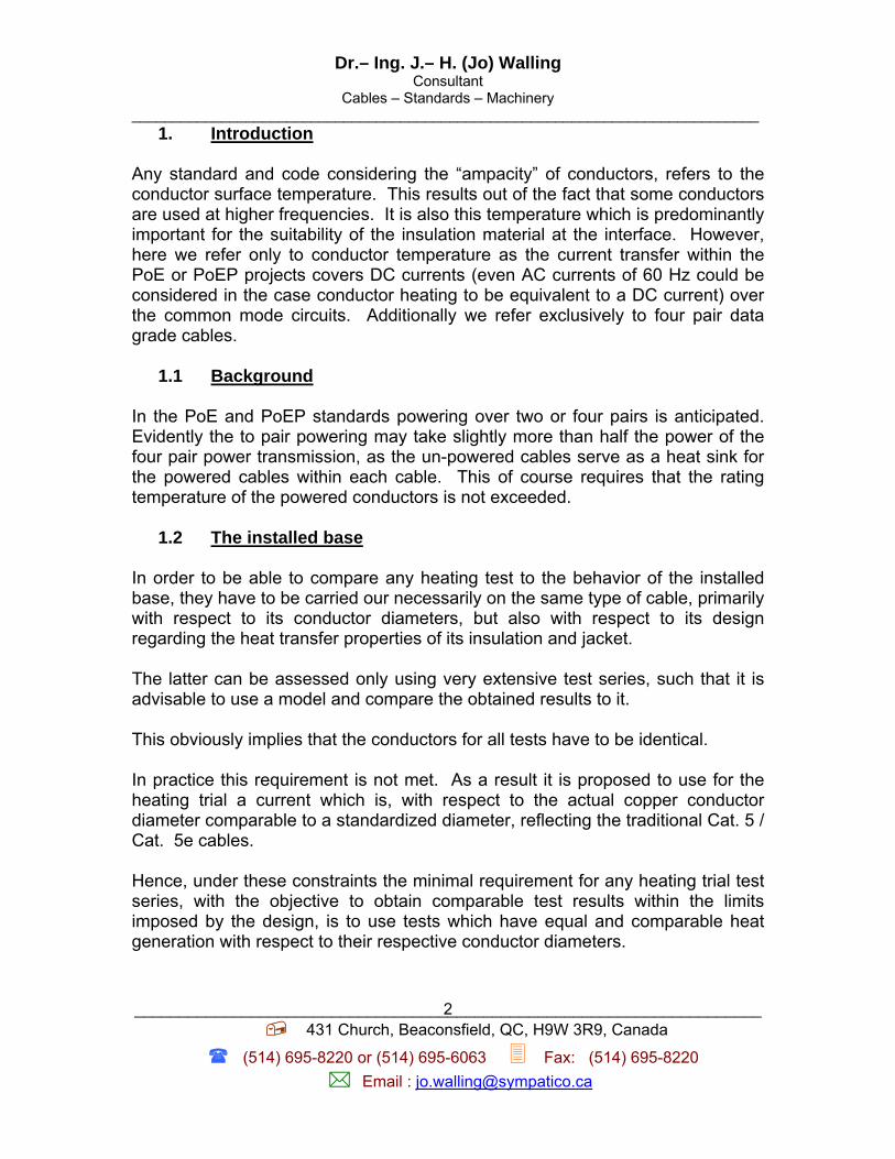
Fig. 1: Cross-section of the cable bundle used for the test.
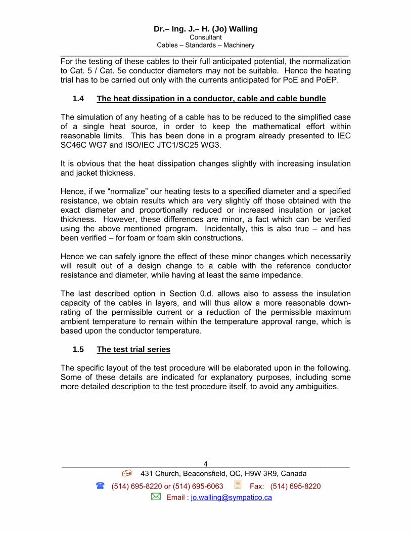
The cables in the bundle shall comprise 37 cables in the densest packing configuration. The cables used for the “temperature” measurement, are also used to concatenate the layers of the bundles, and are shown only in the Fig. 1 as well as in Figs. 5 and 7 showing the lay-plate or the real position of these cables, i.e. on one of the main diagonals of the hexagon. Fig. 2 indicates part of the cable bundle used for the measurement of the temperatures.
Fig. 2: Perspective view of the cable bundle around the measurement cables
indicating the “temperature” measurement leads and those for the concatenation between the cable layers in the bundle

Dr.– Ing. J.– H. (Jo) Walling Consultant
Cables – Standards – Machinery _____________________________________________________________________________
______________________________________________________________________ 431 Church, Beaconsfield, QC, H9W 3R9, Canada
(514) 695-8220 or (514) 695-6063 Fax: (514) 695-8220
Email : [email protected]
6
1.6 The temperature measurement To measure the conductor temperature poses a problem. To measure the resistance of one conductor as a means to determine the temperature may be objectionable. The use of thermocouples or resistance temperature probes in a cable bundle would yield only a point measurement. Furthermore these thermocouples or probes will have to be very small and the problem of introducing them up to the conductor surface is very difficult, if not impossible without destroying the integrity of the cable. To measure the jacket surface temperature in a cable bundle does not allow a direct conclusion on the conductor temperature, hence the measurement of the jacket surface temperature has to be discarded. As a result it is proposed to use the pairs of those cables which are powered to assess the conductor temperature. This makes it mandatory to measure first their resistance at room–temperature and then follow the voltage across the pairs connected to a constant current source. The schematic to connect the pairs for measuring the temperature is shown in Fig. 3. In the Fig. 3 it is assumed that the pair # 1 and the pair # 4 have the shortest and longest twist lay, respectively, while the pair # 2 and pair # 3 have the intermediate twist lays. It is furthermore assumed that the cable under measurement is exposed to the heating current from a constant current source. In this way we have at least two “pairs” of conductors with the same resistance, in each of the measurement reference cables. This helps also to get faster thermal equilibrium of the temperature across the entire cables used for the temperature measurement.
Fig.3: Connections on both ends of the center cable to obtain two nearly identical “pair”
resistances, which can then be measured using the voltage across these pairs.

Dr.– Ing. J.– H. (Jo) Walling Consultant
Cables – Standards – Machinery _____________________________________________________________________________
______________________________________________________________________ 431 Church, Beaconsfield, QC, H9W 3R9, Canada
(514) 695-8220 or (514) 695-6063 Fax: (514) 695-8220
Email : [email protected]
7
Those cables which are not exposed to a heating current shall be measured with a “floating” resistance meter or a resistance bridge of suitable precision.
Fig. 4: Schematic for connecting the cables in the different layers for alternatively two – and four pair heating
Dr.– Ing. J.– H. (Jo) Walling Consultant
Cables – Standards – Machinery _____________________________________________________________________________
______________________________________________________________________ 431 Church, Beaconsfield, QC, H9W 3R9, Canada
(514) 695-8220 or (514) 695-6063 Fax: (514) 695-8220
Email : [email protected]
8
2. The resistance normalization
The entire Section 2 refers only to “normalized conductor diameter” measurements to assess the performance of the installed base.
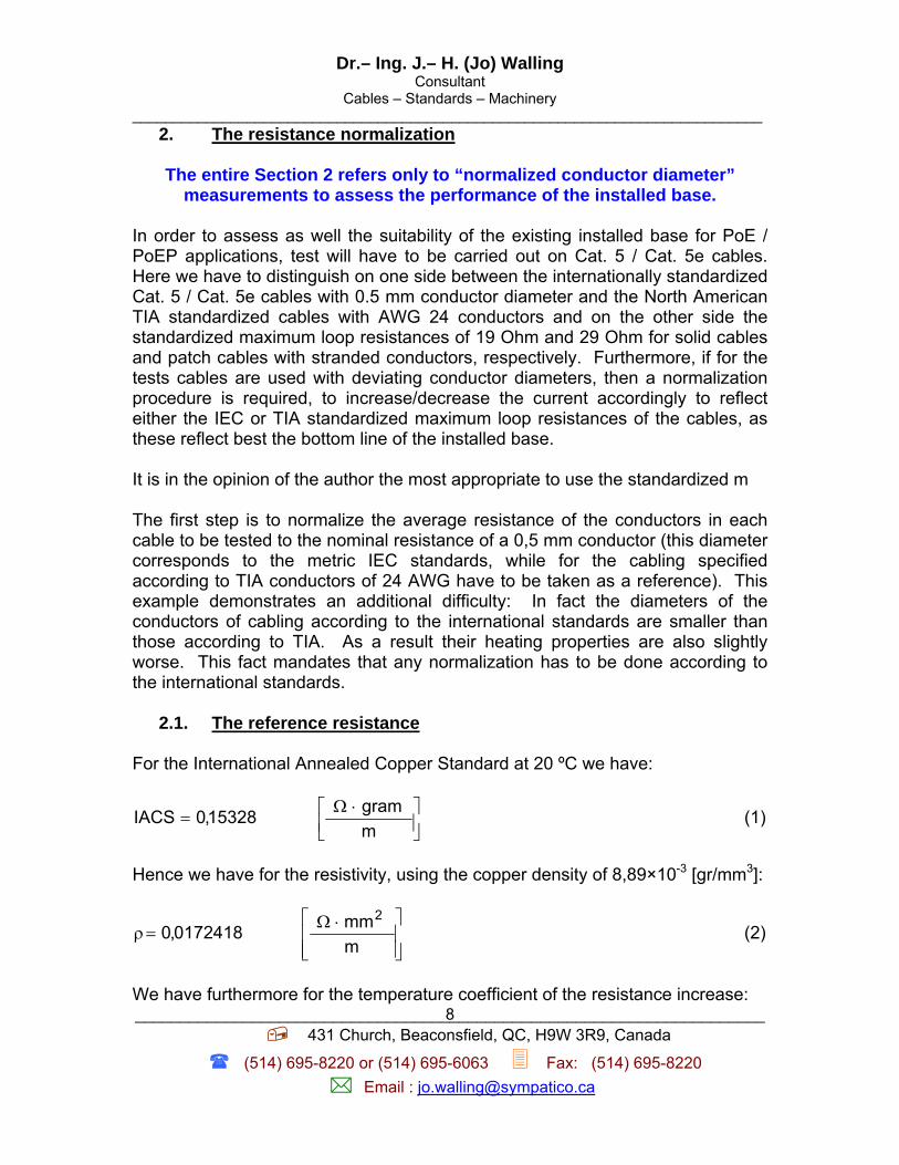
In order to assess as well the suitability of the existing installed base for PoE / PoEP applications, test will have to be carried out on Cat. 5 / Cat. 5e cables. Here we have to distinguish on one side between the internationally standardized Cat. 5 / Cat. 5e cables with 0.5 mm conductor diameter and the North American TIA standardized cables with AWG 24 conductors and on the other side the standardized maximum loop resistances of 19 Ohm and 29 Ohm for solid cables and patch cables with stranded conductors, respectively. Furthermore, if for the tests cables are used with deviating conductor diameters, then a normalization procedure is required, to increase/decrease the current accordingly to reflect either the IEC or TIA standardized maximum loop resistances of the cables, as these reflect best the bottom line of the installed base. It is in the opinion of the author the most appropriate to use the standardized m The first step is to normalize the average resistance of the conductors in each cable to be tested to the nominal resistance of a 0,5 mm conductor (this diameter corresponds to the metric IEC standards, while for the cabling specified according to TIA conductors of 24 AWG have to be taken as a reference). This example demonstrates an additional difficulty: In fact the diameters of the conductors of cabling according to the international standards are smaller than those according to TIA. As a result their heating properties are also slightly worse. This fact mandates that any normalization has to be done according to the international standards.
2.1. The reference resistance
For the International Annealed Copper Standard at 20 ºC we have:
⎥⎦⎤
⎢⎣⎡ ⋅Ω
=mgram15328,0IACS (1)
Hence we have for the resistivity, using the copper density of 8,89×10⁻³ [gr/mm3]:
⎥⎥⎦
⎤
⎢⎢⎣
⎡ ⋅Ω=ρ
mmm0172418,0
2 (2)
We have furthermore for the temperature coefficient of the resistance increase:

Dr.– Ing. J.– H. (Jo) Walling Consultant
Cables – Standards – Machinery _____________________________________________________________________________
______________________________________________________________________ 431 Church, Beaconsfield, QC, H9W 3R9, Canada
(514) 695-8220 or (514) 695-6063 Fax: (514) 695-8220
Email : [email protected]
9
⎥⎦⎤
⎢⎣⎡=α
C100393,0 o (3)
Using these normalizing values we can now calculate the reference resistance for a 0.5 mm diameter copper conductor with a length of 1 m at 20 ºC. We get:
⎥⎦⎤
⎢⎣⎡ Ω
⋅== −
m10781177,8RR 2
dia5,0;C20;m1.fRe o (4)
The Eq (4) indicates our reference resistance to which all our trial have to be normalized.
2.2. The normalization based upon heat generation
The normalization is here referred to only to the horizontal cabling. If patch cables are used, then the normalization has to take care of the inherently higher roundtrip resistance of 0.5 mm diameter of stranded conductors with 7 strands. For the generated heat L of the reference conductor we have:
⎥⎦⎤
⎢⎣⎡⋅=
mWRIL .fRe
2.fRe.fRe (5)
There are two reference currents to be verified, i.e. the actually standardized current for PoE of 0,175 A and the preliminary targeted current for PoEP of 0,420 A both for a 0,5 mm conductors. Hence these values represent our reference current values for calculating the heat generated, L 1Ref. and L 2 Ref.. Therefore, if the average resistance of the cable under test is R Cond then the correspondingly generated heat is:
⎥⎦⎤
⎢⎣⎡⋅=
mWRIL .Cond
2.Cond.Cond (6)
The condition for the normalization is:

Dr.– Ing. J.– H. (Jo) Walling Consultant
Cables – Standards – Machinery _____________________________________________________________________________
______________________________________________________________________ 431 Church, Beaconsfield, QC, H9W 3R9, Canada
(514) 695-8220 or (514) 695-6063 Fax: (514) 695-8220
Email : [email protected]
10
⎥⎦⎤
⎢⎣⎡=
mWLL .Cond.fRe (7)
Hence we get:
]A[R
112445881,005185783,0
RR
II.Cond.Cond
.fRe.fRe.Cond ⋅=⋅= (8)
Here the values in between the vertical lines (|…|) represent the values for 0,175 and 0,420 A, respectively. PoE and PoEP are running and/or are anticipated to run the current over the common mode circuit. Therefore the pairs of the cables are connected together at their ends. Thus the current goes in all the cables surrounding the center cable through the common mode circuit, with the exception of the cables used for measuring the temperature, which are slightly differently connected, see Fig. 3, in order to minimize the resistance differences, and to avoid to the maximum extent un – uniform longitudinal heating in the different pairs, which could affect the measurement accuracy. This is important, especially if we use cables with a cross–web which would act like as heat barrier between the different pairs. As it is not possible to harmonize the resistance across all four pairs, the pairs with the shortest and longest twist lays as well as both pairs the two intermediate twist lays should be combined. In the Fig. 1 these are the blue and brown pairs and the green and red pairs respectively. To make it very clear, if the conductors are greater than 0,5 mm in diameter, then the test current will have to be increased according to Eq (8), in order to assess the approximate real heat dissipation of a comparable cable design, having 0,5 mm diameter. The main objective of the entire exercise is to establish the maximum current limit for the installed base, which consists even up to date basically of Cat. 5 / Cat. 5e cables. Clearly we are in the majority of cases not interested in the potentially higher current carrying capacity of larger conductor diameters, as used in Cat. 6 / Cat. 6A and Cat. 7 / Cat. 7A cables, though we could use them for the heating trial using the above “normalization”.
Dr.– Ing. J.– H. (Jo) Walling Consultant
Cables – Standards – Machinery _____________________________________________________________________________
______________________________________________________________________ 431 Church, Beaconsfield, QC, H9W 3R9, Canada
(514) 695-8220 or (514) 695-6063 Fax: (514) 695-8220
Email : [email protected]
11
However, it should be mentioned, that cables with a shielding over the conductors, hence FEP or SFTP constructions, may behave slightly different, though it is expected, that the difference to UTP cables is very minor. In fact, it is anticipated that the aluminum shielding tape, even if it is a composite tape, helps to even out the temperature difference within the cable and this faster than in a UTP cable.
3. The testing procedure
The testing comprises basically four steps, lined out in the following subsections, be it for each reference current or for each current in case that the resistance normalization is not desired. In the following those cables, used for the temperature measurement are simply referred to a measurement cables.
3.1 Assessment of average measurement cable resistance The first step is to measure the average resistance at the measured ambient room temperature of the measurement cables. It is suggested to carry the trials out in an air conditioned room having limited access to maintain a constant temperature (limiting thus a major change in the convection conditions). This room temperature will have to be measured and recorded. In case of resistance normalization this value is required to adjust the measured average resistance consecutively to a 20 ºC value. It is proposed to use cable bundles of 36 around 1, i.e. a total of 37 individual cables. These should have a minimum length suitable to match the available constant current source, the milli– or micro voltmeter available and the floating resistance meter. Obviously the length limitation is dictated by the maximum voltage range achievable with the constant current source required for testing. If we have for a given cable a specified roundtrip loss of RR in Ω/100m, then we have for the entire resistance – neglecting the small resistance differences resulting out of the helix losses and the way the cables are concatenated – for the cable bundle:
]m/[50
RLR RBB Ω
⋅= (9)
where:

Dr.– Ing. J.– H. (Jo) Walling Consultant
Cables – Standards – Machinery _____________________________________________________________________________
______________________________________________________________________ 431 Church, Beaconsfield, QC, H9W 3R9, Canada
(514) 695-8220 or (514) 695-6063 Fax: (514) 695-8220
Email : [email protected]
12
RB - is the resistance of the concatenated entire cable bundle LB - is the length of the cable bundle RR - is the average resistance of the roundtrip resistance of
the pairs in the cable With the temperature coefficient of the resistance increase:
⎥⎦⎤
⎢⎣⎡=α
C100393,0 o (10)
We have:
( )[ ] [ ]m/tt1L
1RRroomB
BtB Ω−⋅α+⋅
⋅= (11)
where:
RB t - is the resistance of the entire concatenated bundle at the temperature t
t - is the temperature under heating condition in [ °C ] troom - is the room temperature of the air conditioned room Hence the minimum voltage range of the constant current source with a minimum current of I Test has to be at least:
tBTest.minTest RIU ⋅= (12) Hence the constant current source has to have a minimum capacity to cover I Test at U Test min. On the other side the length selected depends on the floating resistance meter (resistance bridge) used to the initial resistance measurement and finally on the available instrument to follow the voltage across the measurement cable pairs. The conductors of each cable are connected in series with respect to their common mode circuits. Either the resistance of the total length of the “common mode” conductor in the cables has to be to be measured or the average round trip resistance of the cable has to be determined (see Section 3.1), and then referenced to 20 ºC.
Dr.– Ing. J.– H. (Jo) Walling Consultant
Cables – Standards – Machinery _____________________________________________________________________________
______________________________________________________________________ 431 Church, Beaconsfield, QC, H9W 3R9, Canada
(514) 695-8220 or (514) 695-6063 Fax: (514) 695-8220
Email : [email protected]
13
If the average resistance of 1 m of common-mode conductor (in the cable) at room temperature is known, then the resistance at a temperature of 20 ºC can be determined:
( )( ) ⎥⎦⎤
⎢⎣⎡ Ω
−⋅α+⋅=
m20t11RR
roommeasured.Cond λ
(13)
Where: Rmeasured - is the measured resistance
l - is the total “common mode” conductor length, contained in the cable
troom - is the measured room temperature α - is the temperature coefficient of resistance increase,
see Eq (10)
3.2 The average roundtrip resistance of the cables If we have for a given cable a specified roundtrip loss of RR in Ω/100m, then we have for the roundtrip resistance – neglecting the small resistance differences resulting out of the helix losses and the way the cables are concatenated – for the average roundtrip resistance of the cable bundle:
]bundleoflengthroundtrip/[L
R50R
B
BR Ω
⋅= (14)
where: RR - is the average resistance of the roundtrip resistance of
the pairs in the cable RB - is the resistance of the concatenated entire cable bundle LB - is the length of the cable bundle
3.3 The bundling of the cables for the heating trial For the bundling of the cables 37 lengths’ have to be prepared, each having the defined length. The measurement cables should be ~1 cm longer than the rest of the cables in order to allow the rather complex connection according to Fig 3. The remaining cable connections are made according to Fig. 5.

Dr.– Ing. J.– H. (Jo) Walling Consultant
Cables – Standards – Machinery _____________________________________________________________________________
______________________________________________________________________ 431 Church, Beaconsfield, QC, H9W 3R9, Canada
(514) 695-8220 or (514) 695-6063 Fax: (514) 695-8220
Email : [email protected]
14
Fig. 5: End connections between the pairs of the peripheral cables around the center cable
33 cables will have to be stripped off their jacket on each end by approximately 8 mm. All the insulation of each conductor should then be stripped by 3 mm. The four measurement cables shall be stripped off its jacket by 13 mm on each end. One conductor of each pair shall then be stripped by 3 mm from its insulation. The remaining conductors of the pairs shall then be back by 5 mm at one end and stripped as before. The insulation of remaining conductor shall then be stripped on each end by 5 mm. The thus prepared cable ends can be further finalized by connecting the conductors pair-wise in series. This can be done on one end completely by twisting the conductors of each pair together. This twist is preferentially to be soldered and insulated it with a very short end of shrink tubing. On the other side the conductors of each two pairs have to be chained and twisted with the exception of the pairs which serve to concatenate the cables in series. Their conductors should be simply twisted together to concatenate them later on after assembling the entire bundle. Their ends shall remain accessible for the different concatenation connections and for measurement purposes. Four measurement cables shall be prepared, one for the center of the bundle and one located in each layer of the bundle, in order to determine the temperature gradient across the layers, starting with the center cable. To simplify the task of bundling the cables it is recommended to use a small plastic plate (a lay-plate) with 36 concentrically arranged holes around a center hole, see Fig. 6. The cables should be laid up parallel, i.e. without a lay.
Dr.– Ing. J.– H. (Jo) Walling Consultant
Cables – Standards – Machinery _____________________________________________________________________________
______________________________________________________________________ 431 Church, Beaconsfield, QC, H9W 3R9, Canada
(514) 695-8220 or (514) 695-6063 Fax: (514) 695-8220
Email : [email protected]
15
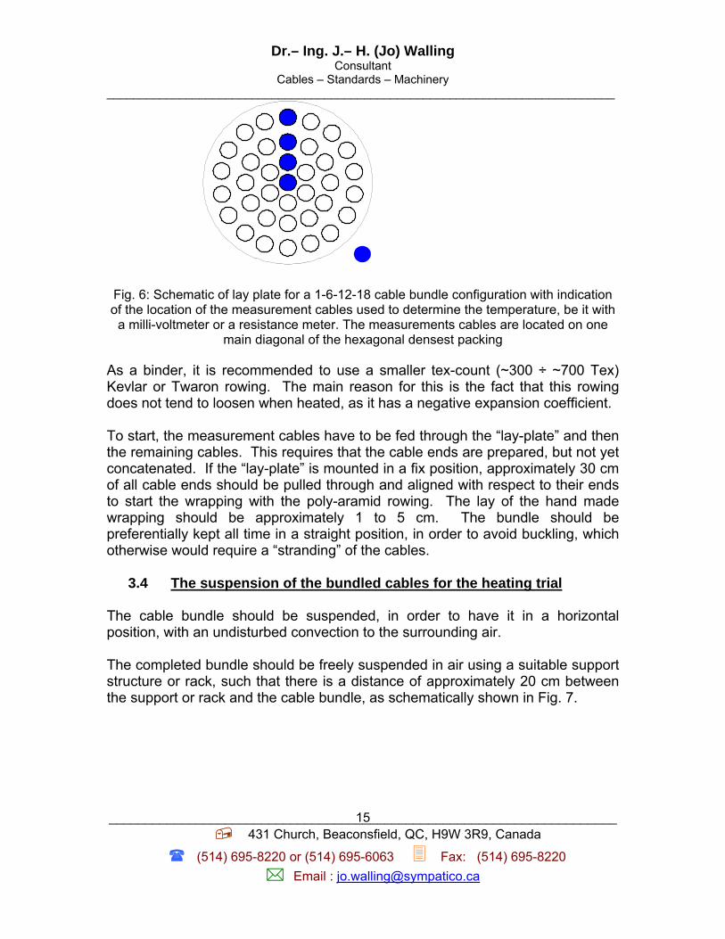
Fig. 6: Schematic of lay plate for a 1-6-12-18 cable bundle configuration with indication of the location of the measurement cables used to determine the temperature, be it with
a milli-voltmeter or a resistance meter. The measurements cables are located on one main diagonal of the hexagonal densest packing
As a binder, it is recommended to use a smaller tex-count (~300 ÷ ~700 Tex) Kevlar or Twaron rowing. The main reason for this is the fact that this rowing does not tend to loosen when heated, as it has a negative expansion coefficient. To start, the measurement cables have to be fed through the “lay-plate” and then the remaining cables. This requires that the cable ends are prepared, but not yet concatenated. If the “lay-plate” is mounted in a fix position, approximately 30 cm of all cable ends should be pulled through and aligned with respect to their ends to start the wrapping with the poly-aramid rowing. The lay of the hand made wrapping should be approximately 1 to 5 cm. The bundle should be preferentially kept all time in a straight position, in order to avoid buckling, which otherwise would require a “stranding” of the cables.
3.4 The suspension of the bundled cables for the heating trial The cable bundle should be suspended, in order to have it in a horizontal position, with an undisturbed convection to the surrounding air. The completed bundle should be freely suspended in air using a suitable support structure or rack, such that there is a distance of approximately 20 cm between the support or rack and the cable bundle, as schematically shown in Fig. 7.

Dr.– Ing. J.– H. (Jo) Walling Consultant
Cables – Standards – Machinery _____________________________________________________________________________
______________________________________________________________________ 431 Church, Beaconsfield, QC, H9W 3R9, Canada
(514) 695-8220 or (514) 695-6063 Fax: (514) 695-8220
Email : [email protected]
16
Fig. 7: Schematic of the suspension of the cable bundle
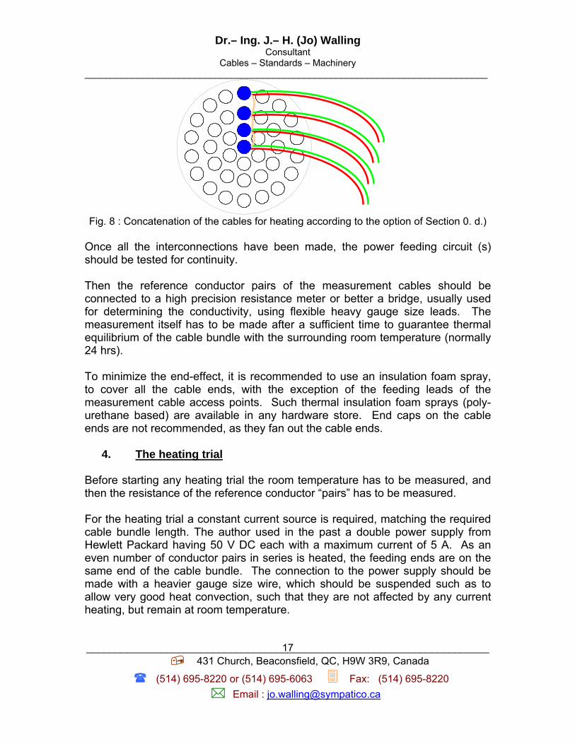
Only when the cable bundle is suspended, the remaining connections between the cable ends can be completed. The remaining cables should be connected in series including the measurement cables. According to the option described in the Scope under Section 0.d is followed, then it is preferable to use the measurement cables also a power feeding cables. Fig. 2 above shows the required concatenation for heating additional layers from the inside towards the outside or from the outside towards the center. This is more detailed indicated in the Fig. 8 which shows clearly the leads for powering (red-blue) of each individual layer, as well as the concatenation (orange) between the layers. Thus it is also feasible to simply heat any layer by itself and measure the resulting temperatures in the other layers, including the center cable. If a small heavier gauge size lead is connected and soldered to the inlet and outlet, without affecting the concatenation of the pairs in between the cables, then the cut back to a lower or higher number of heated layers is easily feasible. In this case it is also feasible to heat only the outer layer for instance and measure the temperatures in the inner layers. This would yield a very good approximation for the required down rating in real installations.
Dr.– Ing. J.– H. (Jo) Walling Consultant
Cables – Standards – Machinery _____________________________________________________________________________
______________________________________________________________________ 431 Church, Beaconsfield, QC, H9W 3R9, Canada
(514) 695-8220 or (514) 695-6063 Fax: (514) 695-8220
Email : [email protected]
17
Fig. 8 : Concatenation of the cables for heating according to the option of Section 0. d.)
Once all the interconnections have been made, the power feeding circuit (s) should be tested for continuity. Then the reference conductor pairs of the measurement cables should be connected to a high precision resistance meter or better a bridge, usually used for determining the conductivity, using flexible heavy gauge size leads. The measurement itself has to be made after a sufficient time to guarantee thermal equilibrium of the cable bundle with the surrounding room temperature (normally 24 hrs). To minimize the end-effect, it is recommended to use an insulation foam spray, to cover all the cable ends, with the exception of the feeding leads of the measurement cable access points. Such thermal insulation foam sprays (poly-urethane based) are available in any hardware store. End caps on the cable ends are not recommended, as they fan out the cable ends.
4. The heating trial Before starting any heating trial the room temperature has to be measured, and then the resistance of the reference conductor “pairs” has to be measured. For the heating trial a constant current source is required, matching the required cable bundle length. The author used in the past a double power supply from Hewlett Packard having 50 V DC each with a maximum current of 5 A. As an even number of conductor pairs in series is heated, the feeding ends are on the same end of the cable bundle. The connection to the power supply should be made with a heavier gauge size wire, which should be suspended such as to allow very good heat convection, such that they are not affected by any current heating, but remain at room temperature.

Dr.– Ing. J.– H. (Jo) Walling Consultant
Cables – Standards – Machinery _____________________________________________________________________________
______________________________________________________________________ 431 Church, Beaconsfield, QC, H9W 3R9, Canada
(514) 695-8220 or (514) 695-6063 Fax: (514) 695-8220
Email : [email protected]
18
The current should be set to either the calculated value according to Eq (8) in case a normalization is required or the specified current for PoE or PoEP. But before connecting the power, it has to be made sure, that the cable bundle is exposed sufficiently long to the surrounding room temperature to attain temperature equilibrium. Only then the room temperature and the resistance of the reference wire shall be measured. Then the current to the conductors shall be switched on and it should be verified, that the current is on the targeted value. It is recommended to wait for at least 24 hours for temperature equilibrium. Then the room temperature should be verified and the resistance of the reference wire should be determined by exactly measuring the current across all wires and the voltage drop across the reference “pairs” of the measurement cables. The resistance then should be normalized to a temperature of 20 °C. The detailed description of the tests is outlined for the consecutive measurements. They are listed in Fig. 9. According to Fig. 9, it is obvious that in Fig. 2 the situation of the 8th trial is indicated. It is furthermore obvious, that the temperature in the first and second layer can be calculated directly from the measurements of the voltage across the corresponding “measurement” cables, whereas the temperature of the center cable and the outer layer of cables has to be measured only using a floating precision resistance meter, as these layers are not subject to any current. The required measurement range and precision of this resistance meter depends obviously on the length of the used cable bundle. In order to attain a thermal equilibrium in the cable bundle during each consecutive heating test, a continuous heating of approximately 36 to 48 hours is required. Between each test series a time of 24 hours is required to equalize the heat in the cable bundle. This time is required for the trials 1 to 6, before undertaking the next trial. For the test trial 7 to 10 an idle time of 48 hors is suggested.
5. The calculation of the conductor temperature of the measurement cables
The previously mentioned 24 hour stabilization temperature is required, as the reference wires of the measurement cables will have to reach the equilibrium temperature on all conductors of these cables.

Dr.– Ing. J.– H. (Jo) Walling Consultant
Cables – Standards – Machinery _____________________________________________________________________________
______________________________________________________________________ 431 Church, Beaconsfield, QC, H9W 3R9, Canada
(514) 695-8220 or (514) 695-6063 Fax: (514) 695-8220
Email : [email protected]
19
We have then for the conductor temperature in the measurement cables under current load conditions:
Fig. 9: Configuration of the test to be carried out on each cable bundle

Dr.– Ing. J.– H. (Jo) Walling Consultant
Cables – Standards – Machinery _____________________________________________________________________________
______________________________________________________________________ 431 Church, Beaconsfield, QC, H9W 3R9, Canada
(514) 695-8220 or (514) 695-6063 Fax: (514) 695-8220
Email : [email protected]
20
[ ]room
measured
Heated.cond
o20
Heated.cond
t1RR1t
C:or
201R
R1t
+⎟⎟⎠
⎞⎜⎜⎝
⎛−⋅
α=
+⎟⎟⎠
⎞⎜⎜⎝
⎛−⋅
α=
(15)
Where:
tCond. - is the temperature of the reference wires of the measurement cables, equivalent to the heated conductor temperatures
RHeated - is the measured resistance after the 24 hour heating period at start
R20 - is the calculated resistance at reference temperature of 20 ºC
The resistance of the heated wire “pairs” is then determined according to the Eq (16):
][I
UR
.Cond
Pairs4Heated Ω= (16)
Where:
U 4 Pairs - is the measured voltage across the reference “pairs”, measured in mV or µV, depending on the length of the cable bundle and the resistance R20
ICond - is the heating current according to Eq (8) re-measured
With Eq (16) we have now the conductor temperature for a 36 around 1 configuration of cables. The results may be normalized to a conductor diameter of 0,5 mm diameter, or refer directly to the actual conductor diameter. The Eq (16) has to be calculated for each measurement cables individually. Using Eq (15) consecutively allows then to determine the conductor temperature in each of the measurement cables, resulting in the gradient across the layers, starting with the center cable and going over the three layers of cables used in the trial. This allows the extrapolation to a higher number of cable layers in the bundle, and allows as well a validation of the Mathcad model before applying it to a lower number of power loaded cables in the bundle.
Dr.– Ing. J.– H. (Jo) Walling Consultant
Cables – Standards – Machinery _____________________________________________________________________________
______________________________________________________________________ 431 Church, Beaconsfield, QC, H9W 3R9, Canada
(514) 695-8220 or (514) 695-6063 Fax: (514) 695-8220
Email : [email protected]
21
6. Heating of two pairs versus all four pairs of a cable Within the framework of IEEE 802.3af (PoE) and IEEE 802.3at (PoEP) the power transmission may be done over two or four pairs. In the above described test series the power transmission over all four pairs has been anticipated, as this definitely yields the highest heat generation within the cable, provided the current in all conductors remains the same. The temperature limitation of cables is coded according to the conductor temperature. The majority of the installed base of cables over which both above mentioned protocols will be deployed is rated to 60 °C. In this context, however, it should be clearly noted that the limiting factor for the temperature is not the insulation material of the pairs, but the jacket material. This is simply due to the fact that the majority of the horizontal cables – at least in North America – have FEP insulated conductors (~80÷90 %) with the remaining percentage having PE insulations. Both these materials qualify for substantially higher permissible temperatures. Main limiting factor are in all cases here the jacket materials1. This is also the main problematic from a safety point of view, which is governing the codes and the there out resulting approval rating standards. Accepting this as a basis, we have to insure that the rating temperature will not be exceeded at the inside surface of the jackets. Generally it can be assumed that the twisted pairs touch the inner surface of the jacket only in a limited amount of longitudinally distributed points. The local spot temperatures of these points can be neglected compared to the total surface of the inside of the jacket. Hence it does not make any major difference if this number of contact points decreases by 50 %. In this case the inner surface temperature of the jacket depends upon the heat generated inside the jacket and the air insulating the heat transfer from the surface of the insulated heating conductors to the inside surface of the jacket. As a result critical is the amount of heat generated within the cable, be it in one, two, three or four pairs. In other words, the conditions prevailing in cables under 4-pair powering and under 2-pair powering can be calculated sufficiently precise based upon a trial on 1 Amazingly the electrical transmission performance of the cables is somewhat improving, as
the cable jacket materials are loosing plasticizer which is highly lossy. As a result the attenuation improves slightly.
Dr.– Ing. J.– H. (Jo) Walling Consultant
Cables – Standards – Machinery _____________________________________________________________________________
______________________________________________________________________ 431 Church, Beaconsfield, QC, H9W 3R9, Canada
(514) 695-8220 or (514) 695-6063 Fax: (514) 695-8220
Email : [email protected]
22
either type of powering. Nordin [1] showed some results, though his calculation method is not detailed, especially with respect to different current levels used.
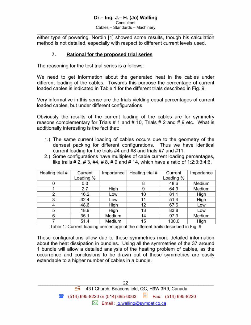
7. Rational for the proposed trial series The reasoning for the test trial series is a follows: We need to get information about the generated heat in the cables under different loading of the cables. Towards this purpose the percentage of current loaded cables is indicated in Table 1 for the different trials described in Fig. 9: Very informative in this sense are the trials yielding equal percentages of current loaded cables, but under different configurations. Obviously the results of the current loading of the cables are for symmetry reasons complementary for Trials # 1 and # 10, Trials # 2 and # 9 etc. What is additionally interesting is the fact that:
1.) The same current loading of cables occurs due to the geometry of the densest packing for different configurations. Thus we have identical current loading for the trials #4 and #8 and trials #7 and #11.
2.) Some configurations have multiples of cable current loading percentages, like trails # 2, # 3, #4, # 8, # 9 and # 14, which have a ratio of 1:2:3:3:4:6.
Heating trial # Current
Loading % Importance Heating trial # Current
Loading % Importance
0 0.0 8 48.6 Medium 1 2.7 High 9 64.9 Medium 2 16.2 Low 10 81.1 High 3 32.4 Low 11 51.4 High 4 48,6 High 12 67.6 Low 5 18.9 High 13 83.8 Low 6 35.1 Medium 14 97.3 Medium 7 51.4 Medium 15 100.0 High
Table 1: Current loading percentage of the different trails described in Fig. 9 These configurations allow due to these symmetries more detailed information about the heat dissipation in bundles. Using all the symmetries of the 37 around 1 bundle will allow a detailed analysis of the heating problem of cables, as the occurrence and conclusions to be drawn out of these symmetries are easily extendable to a higher number of cables in a bundle.
Dr.– Ing. J.– H. (Jo) Walling Consultant
Cables – Standards – Machinery _____________________________________________________________________________
______________________________________________________________________ 431 Church, Beaconsfield, QC, H9W 3R9, Canada
(514) 695-8220 or (514) 695-6063 Fax: (514) 695-8220
Email : [email protected]
23
In the above only cable bundles are considered, which are arranged in a densest packing configuration. This is definitely the worst case, as in reality the cables are somehow randomly packed. For those who would like to extend the above considerations, a study of the packing problem, addressed by Gilbert [2] may yield some very good guidelines.
8. Acknowledgement I should like to mention the help from Dr. James Tyler for the first review of this procedure and having detected and corrected a mistake of my calculations. I am further grateful to Erik Bech who picked up another mistake in the original document and kindly pointed it out to me for correction. I am also indebt to him for his insisting to extend the test method to cover cables with slightly higher conductor diameter for assessing their usefulness to an eventual deployment of PoEP over cabling systems using these cables, though the main intent is to deploy the power transmission system over the existing installed base. Some important modifications of the present document I owe to D. Anderson and E. Bech from Delta Test Labs, Denmark. This modification allows the measurement procedure to be applicable for two or four pair powering of the cables, as suggested by B. Delveaux from Cisco Systems.
9. A note of precaution
So far basically horizontal cables have been considered. However, the cables used for equipment cords and patch cords are frequently bundled in high numbers in the equipment rooms. If these rooms are not air conditioned, then there may be a substantial problem, mainly due to the fat that these stranded cables have a substantially higher resistance. In this case these cables are heating up much higher than the horizontal cables. The work area cords are normally less affected, as they are normally individualized, and as the ambient temperature is normally below 35 °C (above this temperature it is conjectured that the working force is leaving to jump into a swimming pool). Both the types of cables mentioned above may be affected nevertheless by the deployment of “mitigation techniques” to cope with the alien cross-talk problem for the 10GBase-T protocol. In fact several manufactures as well as TIA recommend the utilization for UTP systems of shielded cords both in the work area and the equipment room. Frequently these cords have conductor diameters down to 0.32 mm, thus not even fulfilling the minimum requirement of a down grading of 50 % of the attenuation relative to the horizontal cable.

Dr.– Ing. J.– H. (Jo) Walling Consultant
Cables – Standards – Machinery _____________________________________________________________________________
______________________________________________________________________ 431 Church, Beaconsfield, QC, H9W 3R9, Canada
(514) 695-8220 or (514) 695-6063 Fax: (514) 695-8220
Email : [email protected]
24
As a result these cables heat up to a much higher extent than should be normally expected. Another aspect which requires some precaution from an installation point of view is the fact that bundled cables have not – as is commonly assumed the worst heating conditions. In fact, if the cable jackets in the bundle are in tight contact, then the heat transfer to the environment is better than in some loosely bundled cables. In fact the polymeric material of the jackets has a better heat conductivity than air, hence loosely bundled cables heat up more, if the looseness is such as to create air layers between the cables, which are not large enough as to allow a continuous air draft through the cable bundle, thus carrying heat out of the bundle into the environment. This aspect has to be carefully considered in any installation mitigation procedure! Jo Walling Beaconsfield, August 3, 2006 Literature:
[1] Nordin, , R. et al: Cable temperature Rise from power over Ethernet applications
IEEE Contribution nordin_2_0305 [2] Gilbert, E.N.: The packing problem for twisted pairs Bell System Technical Journal 58 (1979),10 p. 2143 – 2162