Problems of the 13th International Physics Olympiad ... · 1 Problems of the 13th International...
20
1 Problems of the 13th International Physics Olympiad (Malente, 1982) Gunter Lind & Gunnar Friege 1 Leibniz-Institute for Science Education (IPN) at the University of Kiel, Germany Abstract The 13th International Physics Olympiad took place in 1982 in the Federal Republic of Germany. This article contains the competition problems, their solutions and a grading scheme. Introduction In 1982 the Federal Republic of Germany was the first host of the Physics Olympiad outside the so-called Eastern bloc. The 13th International Physics Olympiad took place in Malente, Schleswig-Holstein. The competition was funded by the German Federal Ministry of Science and Education. The organisational guidelines were laid down by the work group “Olympiads for pupils” of the conference of ministers of education of the German federal states. The Institute for Science Education (IPN) at the University of Kiel was responsible for the realisation of the event. A commission of professors, whose chairman was appointed by the German Physical Society, were concerned with the formulation of the competition problems. All other members of the commission came from physics department of the university of Kiel or from the college of education at Kiel. The problems as usual covered different fields of classical physics. In 1982 the pupils had to deal with three theoretical and two experimental problems, whereas at the previous Olympiads only one experimental task was given. However, it seemed to be reasonable to put more stress on experimental work. The degree of difficulty was well balanced. One of the theoretical problems could be considered as quite simple (problem 3: “hot-air balloon”). Another theoretical problem (problem 1: “fluorescent lamp”) had a mean degree of difficulty and the distribution of the points was a normal distribution with only a few 1 Contact: Leibniz-Institute for Science Education (IPN) at the University of Kiel Olshausenstrasse 62, 24098 Kiel, Germany [email protected]
Transcript of Problems of the 13th International Physics Olympiad ... · 1 Problems of the 13th International...
1
Problems of the 13th International Physics Olympiad
(Malente, 1982)
Gunter Lind & Gunnar Friege 1
Leibniz-Institute for Science Education (IPN) at the University of Kiel, Germany
Abstract
The 13th International Physics Olympiad took place in 1982 in the Federal Republic of
Germany. This article contains the competition problems, their solutions and a grading
scheme.
Introduction
In 1982 the Federal Republic of Germany was the first host of the Physics Olympiad
outside the so-called Eastern bloc. The 13th International Physics Olympiad took place in
Malente, Schleswig-Holstein. The competition was funded by the German Federal
Ministry of Science and Education. The organisational guidelines were laid down by the
work group “Olympiads for pupils” of the conference of ministers of education of the
German federal states. The Institute for Science Education (IPN) at the University of Kiel
was responsible for the realisation of the event. A commission of professors, whose
chairman was appointed by the German Physical Society, were concerned with the
formulation of the competition problems. All other members of the commission came from
physics department of the university of Kiel or from the college of education at Kiel.
The problems as usual covered different fields of classical physics. In 1982 the pupils had
to deal with three theoretical and two experimental problems, whereas at the previous
Olympiads only one experimental task was given. However, it seemed to be reasonable to
put more stress on experimental work. The degree of difficulty was well balanced. One of
the theoretical problems could be considered as quite simple (problem 3: “hot-air
balloon”). Another theoretical problem (problem 1: “fluorescent lamp”) had a mean degree
of difficulty and the distribution of the points was a normal distribution with only a few
1 Contact: Leibniz-Institute for Science Education (IPN) at the University of KielOlshausenstrasse 62, 24098 Kiel, [email protected]
excellent and only a few unsatisfying solutions. The third problem (problem 2: “oscillation
coat hanger”) turned out to be the most difficult problem. This problem was generally
considered as quite interesting because different ways of solving were possible. About one
third of the pupils did not find an adequate start to the problem, but nearly one third of the
pupils was able to solve the substantial part of the problem. That means, this problem
polarized between the pupils. The two experimental tasks were quite different in respect of
the input for the experimental setup and the time required for dealing with the problems,
whereas they were quite similar in the degree of difficulty. Both required demandingly
theoretical considerations and experimental skills. Both experimental problems turned out
to be rather difficult. The tasks were composed in a way that on the one hand almost every
pupil had the possibility to come to certain partial results and that there were some
difficulties on the other hand which could only be solved by very few pupils. The
difficulty in the second experimental problem (problem5: “motion of a rolling cylinder”)
was the explanation of the experimental results, which were initially quite surprising. The
difficulty in the other task (problem 4: “lens experiment") was the revealing of an
observation method with a high accuracy (parallax). The five hours provided for solving
the two experimental problems were slightly too short. According to that, in both
experiments only a few pupils came up with excellent solutions. In problem 5 nobody got
the full points.
The problems presented here are based on the original German and English versions of the
competition problems. The solutions are complete but in some parts condensed to the
essentials. Almost all of the original hand-made figures are published here.
Theoretical Problems
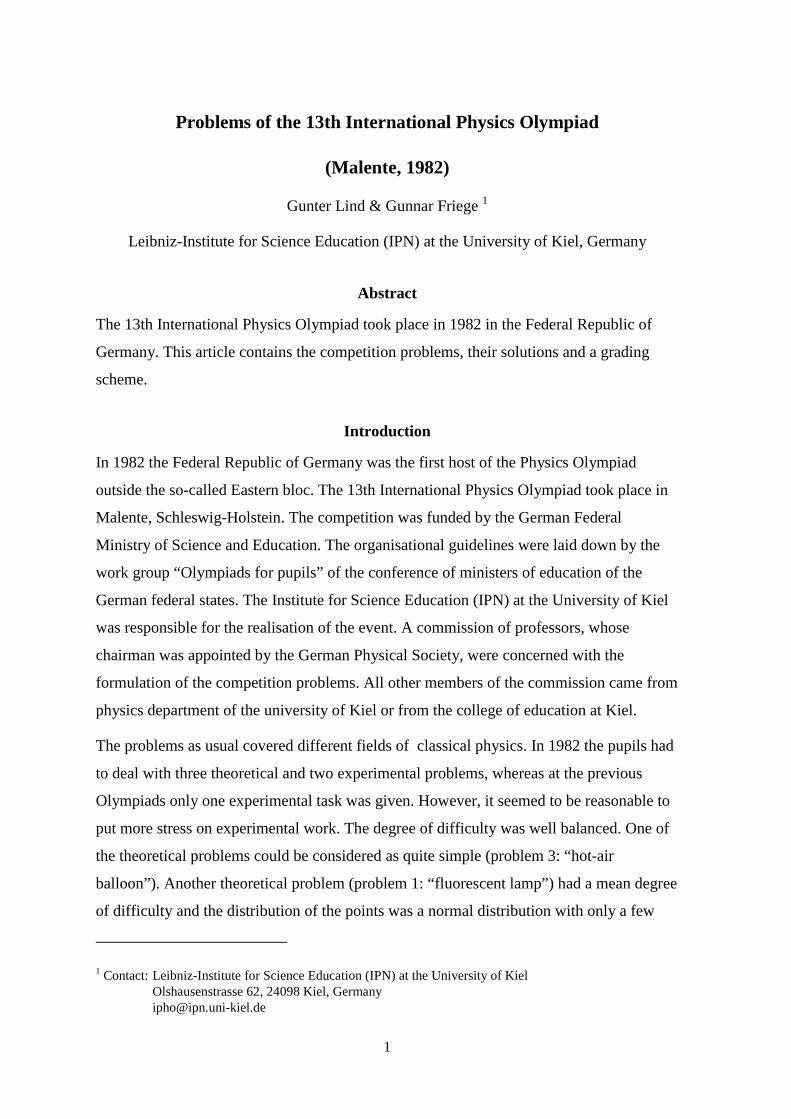
Problem 1: Fluorescent lamp
An alternating voltage of 50 Hz frequency is applied to the fluorescent lamp shown in the
accompanying circuit diagram.
2
3
The following quantities are measured:
overall voltage (main voltage) U = 228.5 V
electric current I = 0.6 A
partial voltage across the fluorescent lamp U’ = 84 V
ohmic resistance of the series reactor dR 26.3= Ω
The fluorescent lamp itself may be considered as an ohmic resistor in the calculations.
a) What is the inductance L of the series reactor?
b) What is the phase shift ϕ between voltage and current?
c) What is the active power Pw transformed by the apparatus?
d) Apart from limiting the current the series reactor has another important function. Name
and explain this function!
Hint: The starter includes a contact which closes shortly after
switching on the lamp, opens up again and stays open.
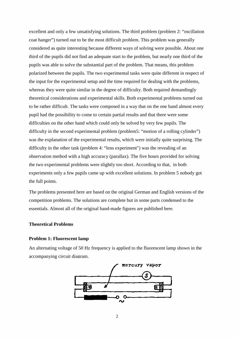
e) In a diagram with a quantitative time scale sketch the time sequence of the luminous
flux emitted by the lamp.
f) Why has the lamp to be ignited only once although the applied alternating voltage goes
through zero in regular intervals?
g) According to the statement of the manufacturer, for a fluorescent lamp of the described
type a capacitor of about 4.7 µF can be switched in series with the series reactor. How
does this affect the operation of the lamp and to what intent is this possibility provided
for?
h) Examine both halves of the displayed demonstrator lamp with the added spectroscope.
Explain the differences between the two spectra. You may walk up to the lamp and you
may keep the spectroscope as a souvenir.
S
4
Solution of problem 1:
a) The total resistance of the apparatus is 228.5VZ 380.80.6A
= = Ω ,
the ohmic resistance of the tube is R84 VR 1400.6 A
= = Ω .
Hence the total ohmic resistance is R 140 26.3 166.3= Ω + Ω = Ω .
Therefore the inductance of the series reactor is: 2 2L Z R 342.6ω⋅ = − = Ω .
This yields 1
342.6L 1.09 H100 s−
Ω= =
π.
b) The impedance angle is obtained from L 342.6tan 2.06R 166.3ω⋅ Ω
ϕ = = =Ω
.
Thus o64.1ϕ = .
c) The active power can be calculated in different ways:
1) owP U I cos 228.5V 0.6 A cos 64.1 59.88 W= ⋅ ⋅ ϕ = ⋅ ⋅ =
2) 2 2wP R I 166.3 (0.6 A) 59.87 W= ⋅ = Ω ⋅ =
d) By opening the contact in the starter a high induction voltage is produced across the
series reactor (provided the contact does not open exactly the same moment, when the
current goes through zero). This voltage is sufficient to ignite the lamp. The main
voltage itself, however, is smaller than the ignition voltage of the fluorescent tube.
e)
f) The recombination time of the ions and electrons in the gaseous discharge is
sufficiently large.
5
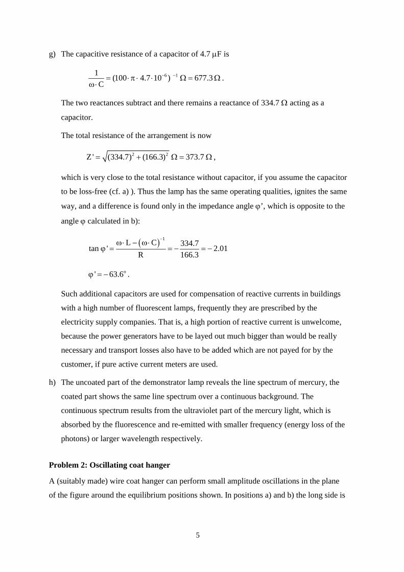
g) The capacitive resistance of a capacitor of 4.7 µF is
6 11 (100 4.7 10 ) 677.3C
− −= ⋅π ⋅ ⋅ Ω = Ωω⋅
.
The two reactances subtract and there remains a reactance of 334.7 Ω acting as a
capacitor.
The total resistance of the arrangement is now
2 2Z ' (334.7) (166.3) 373.7= + Ω = Ω ,
which is very close to the total resistance without capacitor, if you assume the capacitor
to be loss-free (cf. a) ). Thus the lamp has the same operating qualities, ignites the same
way, and a difference is found only in the impedance angle ϕ’, which is opposite to the
angle ϕ calculated in b):
( ) 1L C 334.7tan ' 2.01R 166.3
−ω⋅ − ω⋅ϕ = = − = −
o' 63.6ϕ = − .
Such additional capacitors are used for compensation of reactive currents in buildings
with a high number of fluorescent lamps, frequently they are prescribed by the
electricity supply companies. That is, a high portion of reactive current is unwelcome,
because the power generators have to be layed out much bigger than would be really
necessary and transport losses also have to be added which are not payed for by the
customer, if pure active current meters are used.
h) The uncoated part of the demonstrator lamp reveals the line spectrum of mercury, the
coated part shows the same line spectrum over a continuous background. The
continuous spectrum results from the ultraviolet part of the mercury light, which is
absorbed by the fluorescence and re-emitted with smaller frequency (energy loss of the
photons) or larger wavelength respectively.
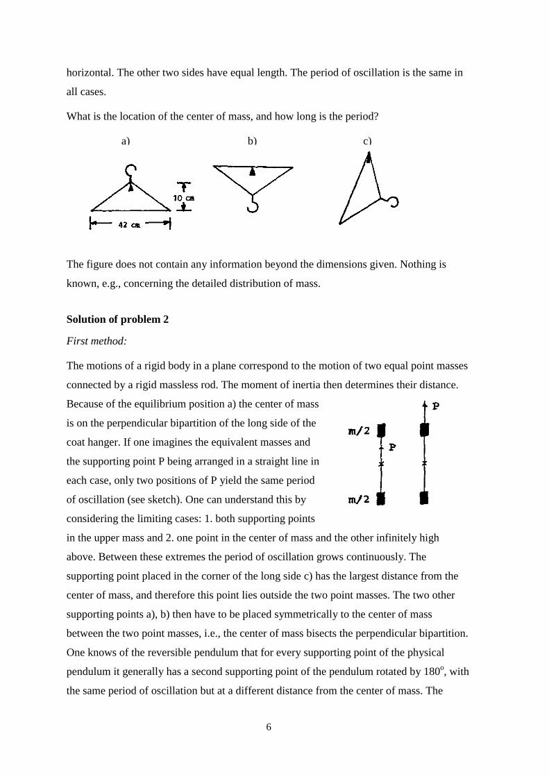
Problem 2: Oscillating coat hanger
A (suitably made) wire coat hanger can perform small amplitude oscillations in the plane
of the figure around the equilibrium positions shown. In positions a) and b) the long side is
6
horizontal. The other two sides have equal length. The period of oscillation is the same in
all cases.
What is the location of the center of mass, and how long is the period?
a) b) c)
The figure does not contain any information beyond the dimensions given. Nothing is
known, e.g., concerning the detailed distribution of mass.
Solution of problem 2
First method:
The motions of a rigid body in a plane correspond to the motion of two equal point masses
connected by a rigid massless rod. The moment of inertia then determines their distance.
Because of the equilibrium position a) the center of mass
is on the perpendicular bipartition of the long side of the
coat hanger. If one imagines the equivalent masses and
the supporting point P being arranged in a straight line in
each case, only two positions of P yield the same period
of oscillation (see sketch). One can understand this by
considering the limiting cases: 1. both supporting points
in the upper mass and 2. one point in the center of mass and
above. Between these extremes the period of oscillation gro
supporting point placed in the corner of the long side c) has
center of mass, and therefore this point lies outside the two
supporting points a), b) then have to be placed symmetricall
between the two point masses, i.e., the center of mass bisect
One knows of the reversible pendulum that for every suppo
pendulum it generally has a second supporting point of the p
the same period of oscillation but at a different distance from
the other infinitely high
ws continuously. The
the largest distance from the
point masses. The two other
y to the center of mass
s the perpendicular bipartition.
rting point of the physical
endulum rotated by 180o, with
the center of mass. The
7
section between the two supporting points equals the length of the corresponding
mathematical pendulum. Therefore the period of oscillation is obtained through the
corresponding length of the pendulum sb + sc , where sb = 5 cm and 2 2cs 5 21= + cm, to
be T = 1.03 s .
Second method:
Let s denote the distance between the supporting point and the center of mass, m the
mass itself and θ the moment of inertia referring to the supporting point. Then we have
the period of oscillation T :
T 2m g sθ
= π⋅ ⋅
, (1)
where g is the acceleration of gravity, g = 9.81 m/s2. Here θ can be obtained from the
moment of inertia θo related to the center of mass:
20 m sθ = θ + ⋅ (2)
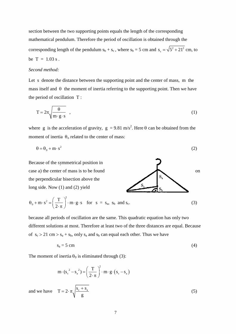
Because of the symmetrical position in
case a) the center of mass is to be found
the perpendicular bisection above the
long side. Now (1) and (2) yield
22
0Tm s m g s for
2⎛ ⎞θ + ⋅ = ⋅ ⋅ ⋅⎜ ⎟⋅π⎝ ⎠
s = sa, sb an
because all periods of oscillation are the same. T
different solutions at most. Therefore at least two
of sc > 21 cm > sa + sb, only sa and sb can equal e
sa = 5 cm
The moment of inertia θ0 is eliminated through (
(2
2 2c a c
Tm (s s ) m g s2
⎛ ⎞⋅ − = ⋅ ⋅ ⋅⎜ ⎟⋅ π⎝ ⎠
and we have c as sT 2g+
= ⋅π
on
d sc. (3)
his quadratic equation has only two
of the three distances are equal. Because
ach other. Thus we have
(4)
3):
)as−
(5)
8
with the numerical value T 1.03 s= ,
which has been rounded off after two decimals because of the accuracy of g.
Third method:
This solution is identical to the previous one up to equation (2).
From (1) and (2) we generally have for equal periods of oscillation T1 = T2:
20 1
1
m sm g s
θ + ⋅⋅ ⋅
= 2
0 2
2
m sm g s
θ + ⋅⋅ ⋅
and therefore ( ) ( )2 22 0 1 1 0 2s m s s m s⋅ θ + ⋅ = ⋅ θ + ⋅
or ( ) ( )2 1 0 1 2s s m s s 0− ⋅ θ − ⋅ = (6)
The solution of (6) includes two possibilities: 01 2 1 2s s or s s
mθ
= ⋅ =
Let 2⋅a be the length of the long side and b the height of the coat hanger. Because of
Tb = Tc we then have 0b c b ceither s s or s s
mθ
= ⋅ = , where 2 2c bs s a= + ,
which excludes the first possibility. Thus 0b cs s
mθ
⋅ = . (7)
For Ta = Tb the case sa ⋅ sb = 0
mθ is excluded because of eq. (7), for we have
a bs s⋅ < 0c bs s
mθ
⋅ = .
Hence 2 2a b c
1 1s s b, s b a2 4
= = = +
and
20 2bb c b
b b
s s s smT 2 2g s g s
θ+ ⋅ +
= ⋅π = π⋅ ⋅
The numerical calculation yields the value T 1.03 s= .
9
Problem 3: Hot-air-balloon
Consider a hot-air balloon with fixed volume VB = 1.1 m3. The mass of the balloon-
envelope, whose volume is to be neglected in comparison to VB, is mH = 0.187 kg.
The balloon shall be started, where the external air temperature is 1ϑ = 20 oC and the
normal external air pressure is po = 1.013 ⋅ 105 Pa. Under these conditions the density of
air is ρ1 = 1.2 kg/m3.
a) What temperature 2ϑ must the warmed air inside the balloon have to make the balloon
just float?
b) First the balloon is held fast to the ground and the internal air is heated to a steady-state
temperature of 3ϑ = 110 oC. The balloon is fastened with a rope.
Calculate the force on the rope.
c) Consider the balloon being tied up at the bottom (the density of the internal air stays
constant). With a steady-state temperature 3ϑ = 110 oC of the internal air the balloon
rises in an isothermal atmosphere of 20 oC and a ground pressure of
p0 = 1.013 ⋅ 105 Pa. Which height h can be gained by the balloon under these
conditions?
d) At the height h the balloon (question c)) is pulled out of its equilibrium position by
10 m and then is released again.
Find out by qualitative reasoning what kind of motion it is going to perform!
Solution of problem 3:
a) Floating condition:
The total mass of the balloon, consisting of the mass of the envelope mH and the mass
of the air quantity of temperature 2ϑ must equal the mass of the displaced air quantity
with temperature 1ϑ = 20 oC.
VB ⋅ ρ2 + mH = VB ⋅ ρ1
H2 1
B
mV
ρ = ρ − (1)
10
Then the temperature may by obtained from
1 2
2 1
TT
ρ=
ρ,
12 1
2
T Tρ= ⋅ρ
= 341.53 K = 68.38 °C (2)
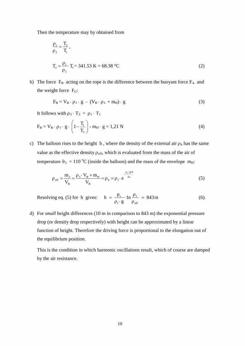
b) The force FB acting on the rope is the difference between the buoyant force FA and
the weight force FG:
FB = VB ⋅ ρ1 ⋅ g - (VB ⋅ ρ3 + mH) ⋅ g (3)
It follows with ρ3 ⋅ T3 = ρ1 ⋅ T1
FB = VB ⋅ ρ1 ⋅ g ⋅ 1
3
T1T
⎛ ⎞−⎜ ⎟
⎝ ⎠ - mH ⋅ g = 1,21 N (4)
c) The balloon rises to the height h , where the density of the external air ρh has the same
value as the effective density ρeff, which is evaluated from the mass of the air of
temperature ϑ3 = 110 oC (inside the balloon) and the mass of the envelope mH:
1
0
g h
3 B H2eff h 1
B B
V mm eV V
ρ ⋅ ⋅−
ρρ ⋅ +ρ = = = ρ = ρ ⋅ (5)
Resolving eq. (5) for h gives: o 1
1 eff
ph 1n 843mg
ρ= ⋅ =
ρ ⋅ ρ(6).
d) For small height differences (10 m in comparison to 843 m) the exponential pressure
drop (or density drop respectively) with height can be approximated by a linear
function of height. Therefore the driving force is proportional to the elongation out of
the equilibrium position.
This is the condition in which harmonic oscillations result, which of course are damped
by the air resistance.
11
Experimental Problems
Problem 4: Lens experiment
The apparatus consists of a symmetric biconvex lens, a plane mirror, water, a meter stick,
an optical object (pencil), a supporting base and a right angle clamp. Only these parts may
be used in the experiment.
a) Determine the focal length of the lens with a maximum error of ± 1 %.
b) Determine the index of refraction of the glass from which the lens is made.
The index of refraction of water is nw = 1.33. The focal length of a thin lens is given by
( )1 2
1 1 1n 1f r r
⎛ ⎞= − ⋅ −⎜ ⎟
⎝ ⎠,
where n is the index of refraction of the lens material and r1 and r2 are the curvature
radii of the refracting surfaces. For a symmetric biconvex lens we have r1 = - r2 = r, for a
symmetric biconcave lens r1 = - r2 = - r .
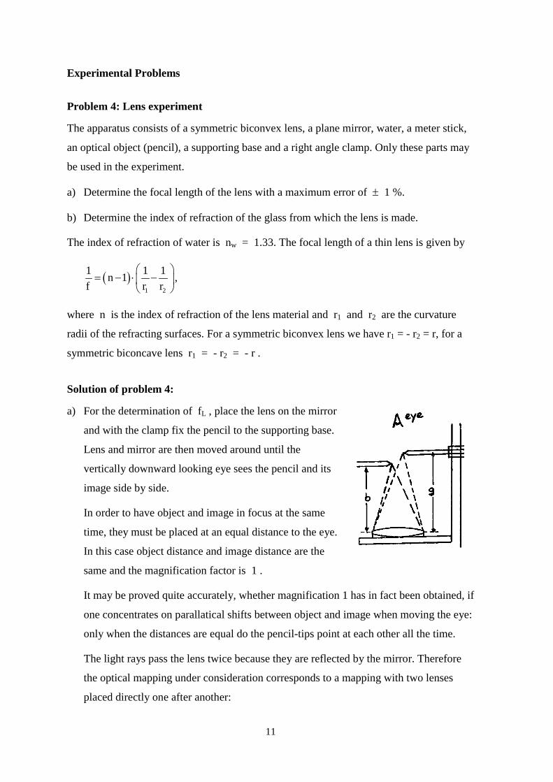
Solution of problem 4:
a) For the determination of fL , place the lens on the mirror
and with the clamp fix the pencil to the supporting base.
Lens and mirror are then moved around until the
vertically downward looking eye sees the pencil and its
image side by side.
In order to have object and image in focus at the same
time, they must be placed at an equal distance to the eye.
In this case object distance and image distance are the
same and the magnification factor is 1 .
It may be proved quite accurately, whether magnification
one concentrates on parallatical shifts between object and
only when the distances are equal do the pencil-tips point
The light rays pass the lens twice because they are reflecte
the optical mapping under consideration corresponds to a
placed directly one after another:
1 has in fact been obtained, if
image when moving the eye:
at each other all the time.
d by the mirror. Therefore
mapping with two lenses
12
L L
1 1 1 1 1 1, whereg b f f f f+ = = +
i.e. the effective focal length f is just half the focal length of the lens. Thus we find for
magnification 1:
LL
2 2g b and i.e. f g.g f
= = =
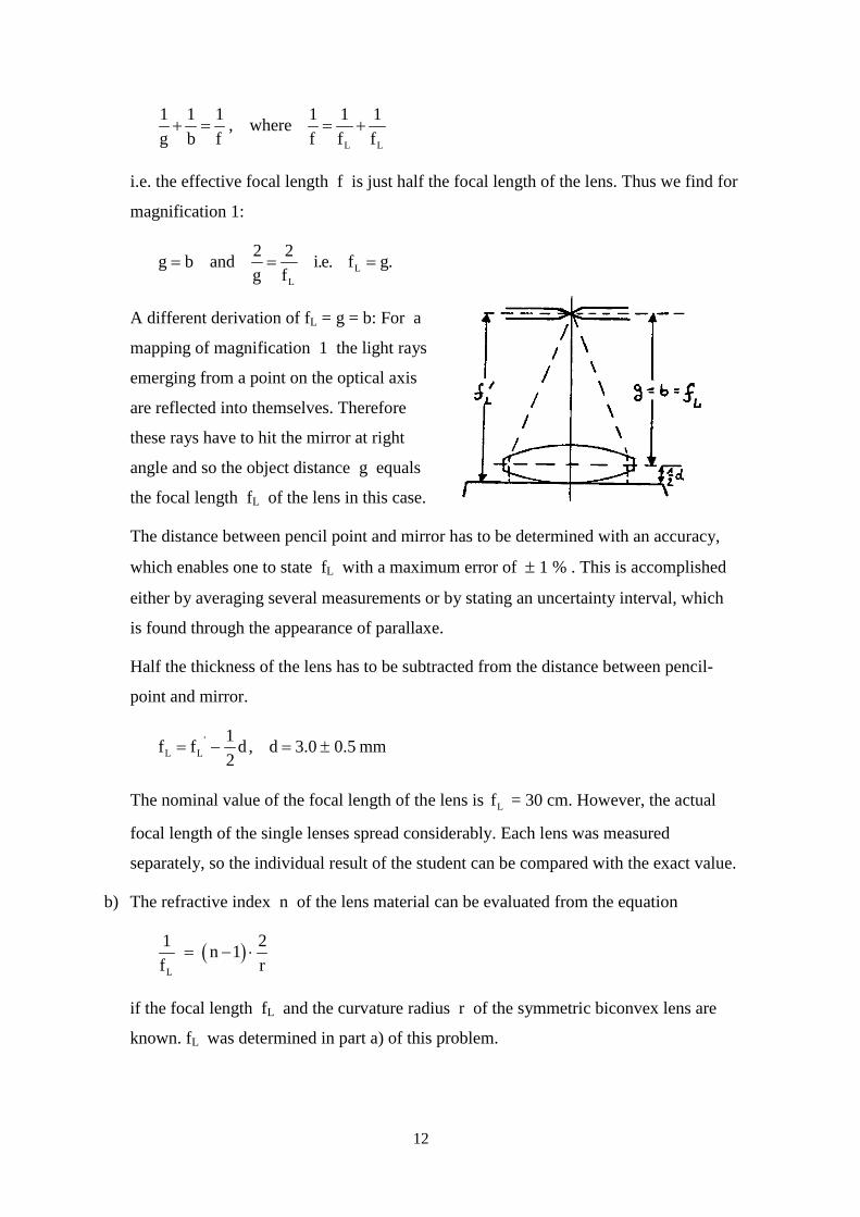
A different derivation of fL = g = b: For a
mapping of magnification 1 the light rays
emerging from a point on the optical axis
are reflected into themselves. Therefore
these rays have to hit the mirror at right
angle and so the object distance g equals
the focal length fL of the lens in this case.
The distance between pencil point and mirro
which enables one to state fL with a maximu
either by averaging several measurements or
is found through the appearance of parallaxe
Half the thickness of the lens has to be subtra
point and mirror.
'L L
1f f d , d 3.0 0.5 mm2
= − = ±
The nominal value of the focal length of the
focal length of the single lenses spread consi
separately, so the individual result of the stud
b) The refractive index n of the lens material c
( )L
1 2n 1f r
= − ⋅
if the focal length fL and the curvature radiu
known. fL was determined in part a) of this p
r has to be determined with an accuracy,
m error of ± 1 % . This is accomplished
by stating an uncertainty interval, which
.
cted from the distance between pencil-
lens is Lf = 30 cm. However, the actual
derably. Each lens was measured
ent can be compared with the exact value.
an be evaluated from the equation
s r of the symmetric biconvex lens are
roblem.
13
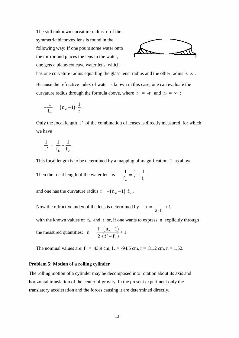
The still unknown curvature radius r of the
symmetric biconvex lens is found in the
following way: If one pours some water onto
the mirror and places the lens in the water,
one gets a plane-concave water lens, which
has one curvature radius equalling the glass len
Because the refractive index of water is known
curvature radius through the formula above, wh
( )ww
1 1n 1 .f r
− = − ⋅
Only the focal length f ' of the combination of
we have
L w
1 1 1f ' f f
= + .
This focal length is to be determined by a mapp
Then the focal length of the water lens isw
1f
and one has the curvature radius ( )wr n 1= − − ⋅
Now the refractive index of the lens is determin
with the known values of fL and r, or, if one w
the measured quantities: ( )( )
w
L
f ' n 1n
2 f ' f⋅ −
=⋅ −
+ 1.
The nominal values are: f ' = 43.9 cm, fw = -94
Problem 5: Motion of a rolling cylinder
The rolling motion of a cylinder may be decompose
horizontal translation of the center of gravity. In the
translatory acceleration and the forces causing it ar
s’ radius and the other radius is ∞ .
in this case, one can evaluate the
ere r1 = -r and r2 = ∞ :
lenses is directly measured, for which
ing of magnification 1 as above.
'L
1 1f f
= −
wf .
ed by L
rn 12 f
= +⋅
ants to express n explicitly through
.5 cm, r = 31.2 cm, n = 1.52.
d into rotation about its axis and
present experiment only the
e determined directly.
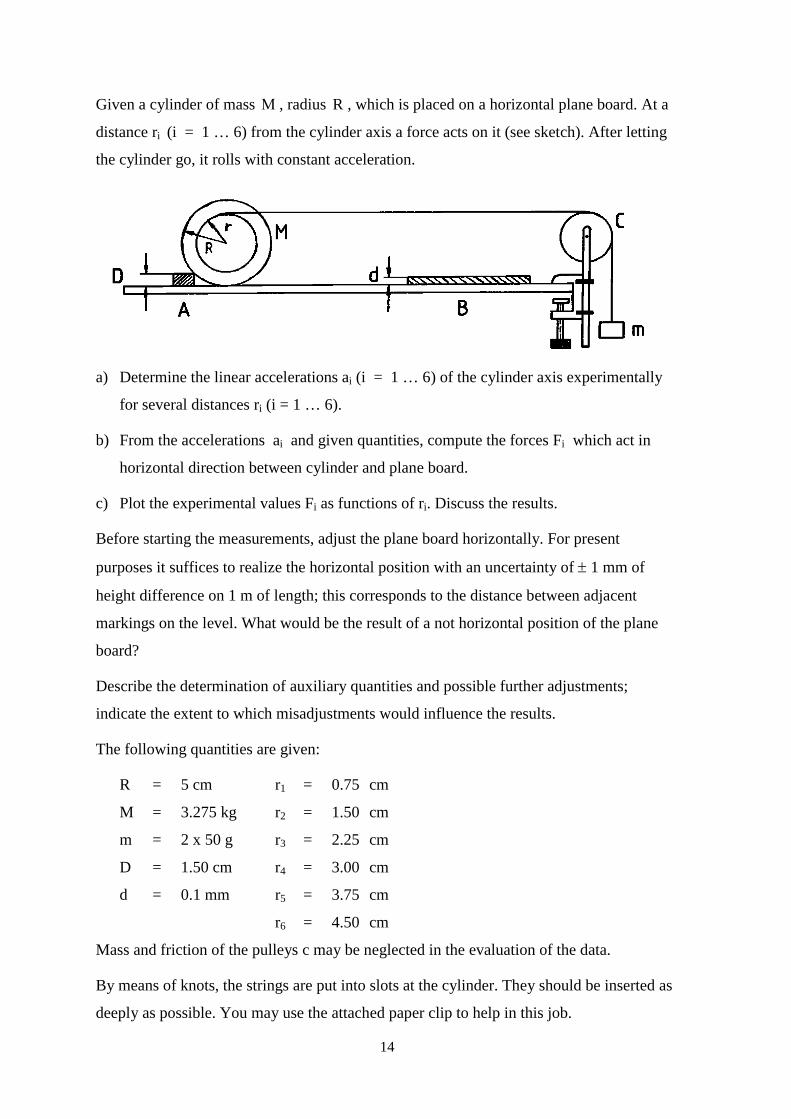
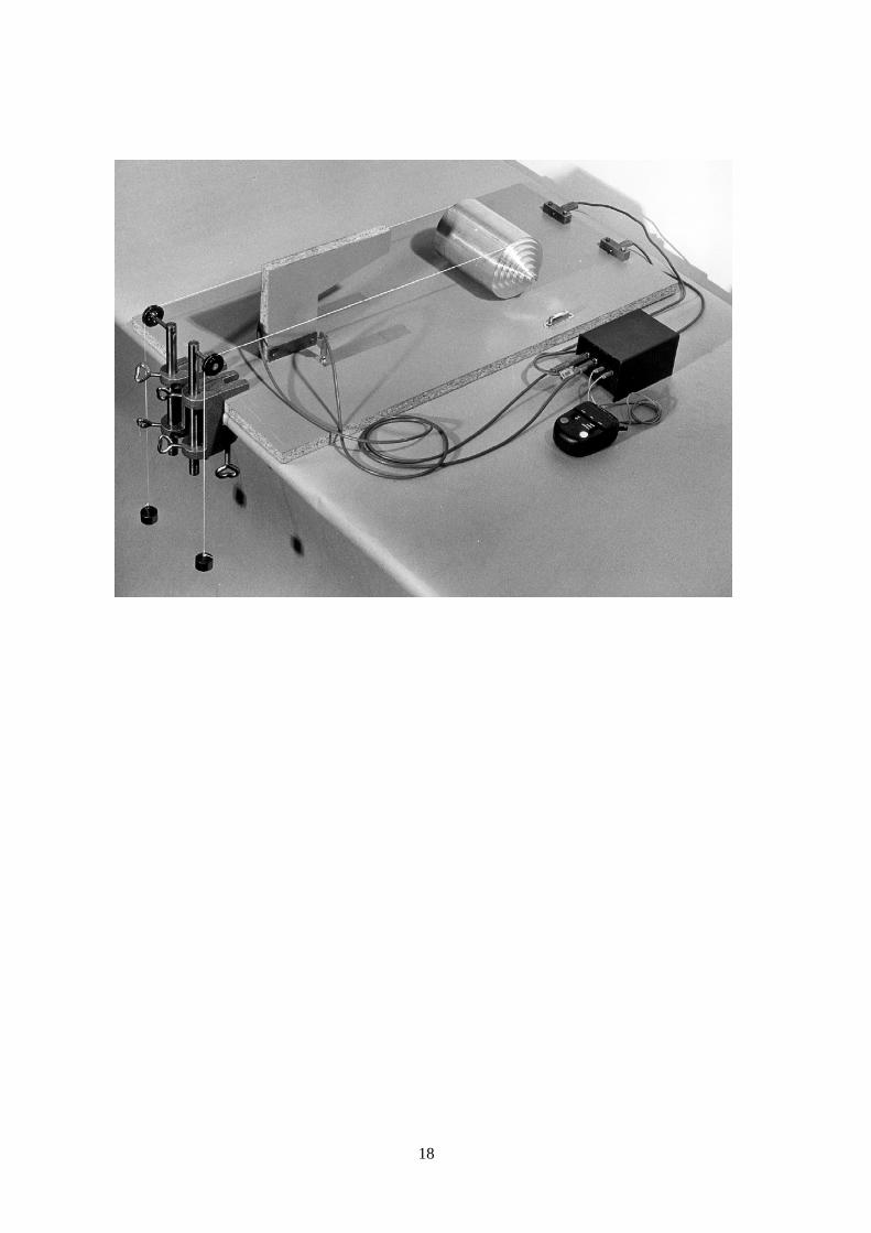
Given a cylinder of mass Μ , radius R , which is placed on a horizontal plane board. At a
distance ri (i = 1 … 6) from the cylinder axis a force acts on it (see sketch). After letting
the cylinder go, it rolls with constant acceleration.
14
a) Determine the linear accelerations ai (i = 1 … 6) of the cylinder axis experimentally
for several distances ri (i = 1 … 6).
b) From the accelerations ai and given quantities, compute the forces Fi which act in
horizontal direction between cylinder and plane board.
c) Plot the experimental values Fi as functions of ri. Discuss the results.
Before starting the measurements, adjust the plane board horizontally. For present
purposes it suffices to realize the horizontal position with an uncertainty of ± 1 mm of
height difference on 1 m of length; this corresponds to the distance between adjacent
markings on the level. What would be the result of a not horizontal position of the plane
board?
Describe the determination of auxiliary quantities and possible further adjustments;
indicate the extent to which misadjustments would influence the results.
The following quantities are given:
R = 5 cm r1 = 0.75 cm
M = 3.275 kg r2 = 1.50 cm
m = 2 x 50 g r3 = 2.25 cm
D = 1.50 cm r4 = 3.00 cm
d = 0.1 mm r5 = 3.75 cm
r6 = 4.50 cm
Mass and friction of the pulleys c may be neglected in the evaluation of the data.
By means of knots, the strings are put into slots at the cylinder. They should be inserted as
deeply as possible. You may use the attached paper clip to help in this job.
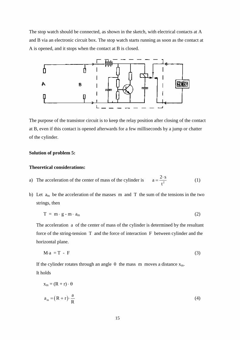
The stop watch should be connected, as shown in the sketch, with electrical contacts at A
and B via an electronic circuit box. The stop watch starts running as soon as the contact at
A is opened, and it stops when the contact at B is closed.
The
at B,
of th
Solu
The
a) T
b) L
s
T
f
h
I
I
15
purpose of the transistor circuit is to keep the relay position after closing of the contact
even if this contact is opened afterwards for a few milliseconds by a jump or chatter
e cylinder.
tion of problem 5:
oretical considerations:
he acceleration of the center of mass of the cylinder is 2
2 sat⋅
= (1)
et am be the acceleration of the masses m and T the sum of the tensions in the two
trings, then
T = m ⋅ g - m ⋅ am (2)
he acceleration a of the center of mass of the cylinder is determined by the resultant
orce of the string-tension T and the force of interaction F between cylinder and the
orizontal plane.
M⋅a = T - F (3)
f the cylinder rotates through an angle θ the mass m moves a distance xm.
t holds
xm = (R + r) ⋅ θ
( )maa R rR
= + ⋅ (4)
16
From (2), (3) and (4) follows rF mg M m 1 aR
⎡ ⎤⎛ ⎞= − + ⋅ + ⋅⎜ ⎟⎢ ⎥⎝ ⎠⎣ ⎦. (5)
c) From the experimental data we see that for small ri the forces M ⋅ a and T are in
opposite direction and that they are in the same direction for large ri .
For small values of r the torque produced by the string-tensions is not large enough to
provide the angular acceleration required to prevent slipping. The interaction force
between cylinder and plane acts into the direction opposite to the motion of the center
of mass and thereby delivers an additional torque.
For large values of r the torque produced by string-tension is too large and the
interaction force has such a direction that an opposed torque is produced.
From the rotary-impulse theorem we find
aT r F RR
⋅ + ⋅ = Ι ⋅θ = Ι ⋅ ,
where Ι is the moment of inertia of the cylinder.
With (3) and (5) you may eliminate T and a from this equation. If the moment of
inertia of the cylinder is taken as 21 R2
Ι = ⋅Μ ⋅ (neglecting the step-up cones) we find
after some arithmetical transformations
2
r1 2RF mg
m r3 2 1M R
− ⋅= ⋅
⎛ ⎞+ ⋅ ⋅ +⎜ ⎟⎝ ⎠
.
For r = 0 m gF m3 2M
⋅→ =
+ ⋅ > 0.
For r = R m gF m3 8M
− ⋅⇒ =
+ ⋅< 0.
Because m 1M
it is approximately 1 2 rF m g3 3 R
= ⋅ − ⋅ .
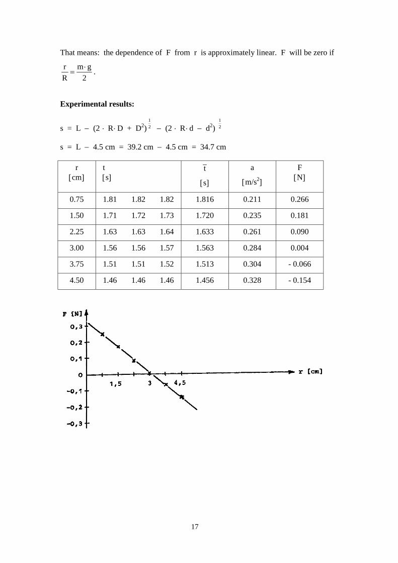
That means: the dependence of F from r is approximately linear. F will be zero if
r m gR 2
⋅= .
Experimental results:
s = L − (2 ⋅ R ⋅D + D2)12 − (2 ⋅ R ⋅d − d2)
12
s = L − 4.5 cm = 39.2 cm − 4.5 cm = 34.7 cm
r[cm]
t[s]
t
[s]
a
[m/s2]
F[N]
0.75 1.81 1.82 1.82 1.816 0.211 0.266
1.50 1.71 1.72 1.73 1.720 0.235 0.181
2.25 1.63 1.63 1.64 1.633 0.261 0.090
3.00 1.56 1.56 1.57 1.563 0.284 0.004
3.75 1.51 1.51 1.52 1.513 0.304 - 0.066
4.50 1.46 1.46 1.46 1.456 0.328 - 0.154
17
18
19
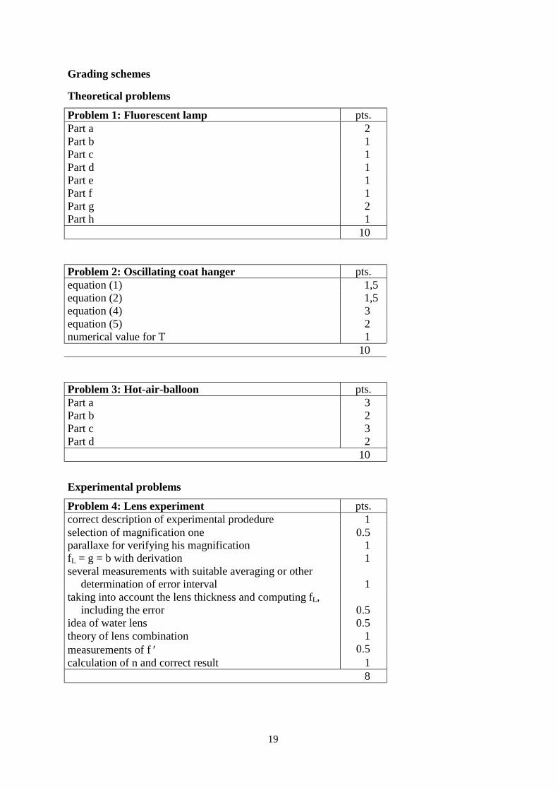
Grading schemes
Theoretical problems
Problem 1: Fluorescent lamp pts.Part a 2Part b 1Part c 1Part d 1Part e 1Part f 1Part g 2Part h 1
10
Problem 2: Oscillating coat hanger pts.equation (1) 1,5equation (2) 1,5equation (4) 3equation (5) 2numerical value for T 1
10
Problem 3: Hot-air-balloon pts.Part a 3Part b 2Part c 3Part d 2
10
Experimental problems
Problem 4: Lens experiment pts.correct description of experimental prodedure 1selection of magnification one 0.5parallaxe for verifying his magnification 1fL = g = b with derivation 1several measurements with suitable averaging or other
determination of error interval 1taking into account the lens thickness and computing fL,
including the error 0.5idea of water lens 0.5theory of lens combination 1measurements of f ′ 0.5calculation of n and correct result 1
8
20
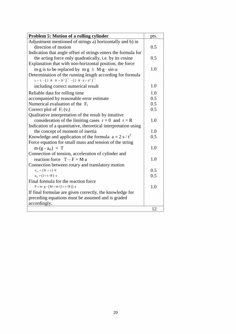
Problem 5: Motion of a rolling cylinder pts.Adjustment mentioned of strings a) horizontally and b) in
direction of motion 0.5Indication that angle offset of strings enters the formula for
the acting force only quadratically, i.e. by its cosine 0.5Explanation that with non-horizontal position, the force
m⋅g is to be replaced by m⋅g ± M⋅g ⋅ sin α 1.0Determination of the running length according for formula
( ) ( )1 / 2 1 / 22 2s L 2 R D D 2 R d d= − ⋅ ⋅ + − ⋅ ⋅ +
including correct numerical result 1.0Reliable data for rolling time 1.0accompanied by reasonable error estimate 0.5Numerical evaluation of the Fi 0.5Correct plot of Fi (vi) 0.5Qualitative interpretation of the result by intuitive
consideration of the limiting cases r = 0 and r = R 1.0Indication of a quantitative, theoretical interpretation using
the concept of moment of inertia 1.0Knowledge and application of the formula a = 2 s / t2 0.5Force equation for small mass and tension of the string
m⋅(g - am) = T 1.0Connection of tension, acceleration of cylinder and
reaction force T – F = M⋅a 1.0Connection between rotary and translatory motion
( )mx R r= + ⋅ θ 0.5( )ma 1 r / R a= + ⋅ 0.5
Final formula for the reaction force( )( )F m g M m 1 r / R a= ⋅ − + ⋅ + ⋅ 1.0
If final formulae are given correctly, the knowledge forpreceding equations must be assumed and is gradedaccordingly.
12

![[Mathematical Olympiad] Math Olympiad Tutorials](https://static.fdocuments.us/doc/165x107/55cf97a6550346d03392cb7e/mathematical-olympiad-math-olympiad-tutorials.jpg)