Problem 1: Calculating deflection by integration – …...Strength of Materials Prof. M. S....
13
Strength of Materials Prof. M. S. Sivakumar Indian Institute of Technology Madras Problem 1: Calculating deflection by integration – uniform load Problem 2: Calculating deflection by integration - triangular load pattern Problem 3: Deflections - by differential equations, concentrated load Problem 4: Deflections by Moment area method – Concentrated load Problem 5: Deflections by Moment area method – Concentrated load Problem 6: Moment Area Method - udl
Transcript of Problem 1: Calculating deflection by integration – …...Strength of Materials Prof. M. S....

Strength of Materials Prof. M. S. Sivakumar
Indian Institute of Technology Madras
Problem 1: Calculating deflection by integration – uniform load
Problem 2: Calculating deflection by integration - triangular load pattern
Problem 3: Deflections - by differential equations, concentrated load
Problem 4: Deflections by Moment area method – Concentrated load
Problem 5: Deflections by Moment area method – Concentrated load
Problem 6: Moment Area Method - udl
Dhandapani
Underline

Strength of Materials Prof. M. S. Sivakumar
Indian Institute of Technology Madras
Problem 1: Calculating deflection by integration – uniform load
A simply supported prismatic beam AB carries a uniformly distributed load of intensity w
over its span L as shown in figure. Develop the equation of the elastic line and find the
maximum deflection δ at the middle of the span.
Figure:
Concepts involved:
Beam defection formula
Formulae used:
d2y/dx2 = M/EI
Solution:
Taking coordinate axes x and y as shown, we have for the bending moment at any point x.
Mx = wLx/2 - wx2/2
And deflection equation becomes
EI d2y/dx2 = wLx/2 - wx2/2.
Multiplying both sides by dx and integrating, we obtain

Strength of Materials Prof. M. S. Sivakumar
Indian Institute of Technology Madras
EI dy/dx = wLx2/4 - wx3/6 + C1, ------------------ Equation 1
Where C1 is an integration constant. To evaluate this constant, we note from symmetry
that when x = L/2, dy/dx = 0. From this condition, we find
C1 - wL3/24
And equation 1 becomes
EI dy/dx = -wLx2/4 + wx3/6 - wL3/24 ------------------ Equation 2
Again multiplying both sides by dx and integrating,
EIy = wLx3/12 - wx4/24 - wL3x/24 + C2
The integration constant C2 is found from the condition that y = 0 when x = 0.
Thus C2 = 0 and the required equation for the elastic line becomes
y = -wx / 24EI (L3 -2Lx2 + x3)
To find the maximum deflection at mid- span, we set x = L/2 in the equation and obtain
| δ | = 5wL4/384EI
The maximum slope θ A at the left end of the beam can be found by setting x = 0 in the
equation 2, which gives
x = 0
dydx
⎛ ⎞⎜ ⎟⎝ ⎠
=> θ A = wL3/24EI.
Top

Strength of Materials Prof. M. S. Sivakumar
Indian Institute of Technology Madras
Problem 2 : Calculating deflection by integration - triangular load pattern
A simply supported beam AB carries a triangularly distributed load as shown in the fig.
Find the equation of the deflection curve referred to the coordinate axes x and y as shown.
Also determine the maximum deflection d .
Figure:
Solution:
In this case we begin directly with deflection equation. We have,
EI d4y/dx4 = - wx/L
Separating variables and integrating twice, we obtain
EIy d2y/dx2 = -wx3/6L + C1 x + C2 ------------------------1
Again, separating variables and performing two more integrations, we obtain
EIy = -wx5/120L + C1 x3/6 + C2 x2/2 + C3 x + C4 ------------2
To find the four constants of integration, we now note that the bending moment,
represented by equation 1, and the deflection, represented by equation 2, both vanish
when x = 0 and when x =L. From these four boundary conditions, we find

Strength of Materials Prof. M. S. Sivakumar
Indian Institute of Technology Madras
C1 = wL/6, C2 = 0, C3 = -7wL3/360, C4 = 0
Substituting these values back into eq.2 and rearranging terms, we obtain
Y - (wx/360LEI) (7L4 – 10L2x2 + 3x4)
To find the maximum deflection d, we first set dy/dx = 0 and find x = 0.519l. Then using
this value of x in the expression for y, the maximum deflection becomes
δmax = | d max | = ymax = 0.00652 wL4/EI
Setting x = L in eq.2, we obtain, the deflection,
δ = | d | = PL3/3EI
Top

Strength of Materials Prof. M. S. Sivakumar
Indian Institute of Technology Madras
Problem 3 : Deflections - by differential equations, concentrated load
A simply supported prismatic beam AB carries a concentrated load P as shown in the
figure. Locate the point of maximum deflection on the elastic line and find the value of this
deflection.
Figure:
Solution:
we have for 0 < x < a,
xx
PaM = L
⎛ ⎞⎜ ⎟⎝ ⎠
While for a < x < L,
xPbM = L
(x - a).
Substituting these expressions for bending moment into deflection equation, we obtain for
the two portions of the deflection curve, the following two differential equations
EI d2y/dx2 = (Pax/ L) for 0 ≤ x ≤ a
EI d2y/dx2 = ( -Pa/L) (L-x) for a ≤ x ≤ L
Strength of Materials Prof. M. S. Sivakumar
Indian Institute of Technology Madras
Successive integration of these equations gives
EI dy/dx = Pax2/2L + C1 ----------------------------- (l) (for 0 ≤ x ≤ a)
EIy = Pax3/6L + C1x + C2 --------------------------- (m) (for 0 ≤ x ≤ a)
EI dy/dx = Pax - Pax2/2L +D1 ----------------------------- (n) (for a ≤ x ≤ L)
EIy = Pax2/2 - Pax3/6L + D1x +D2------------------------ (o) (for a ≤ x ≤ L)
Where C1, C2, D1, D2, are constants of integration. To find these four constants, we have
the following conditions:
1. At x = 0 , y = 0 2. At x = L , y = 0
3. x = a
dydx
⎛ ⎞⎜ ⎟⎝ ⎠
is the same from equations (l) and (n)
4. ( )x = ay is the same from equations (m) and (o)
Using these we get, C1 = Pb/6L (L2 – b2), C2 = 0, D1 = Pa/6L (2L2 + a2), D2 = Pa3/6EI
Using the constants as determined eqs. (m) and (o) defining the two portions of the elastic
line of the beam become
( 2 2 2PbxEIy = - L - b - x6L
⎛ ⎞⎜ ⎟⎝ ⎠
) -------------------------------------(p)
( ) 3 2 2 3PbEIy = L/b (x-a) + (L - b ) x - x6L
⎛ ⎞ ⎡ ⎤⎜ ⎟ ⎣ ⎦⎝ ⎠ --------------------------(q)
For a > b, the maximum deflection will occur in the left portion of the span, to which eq.(p)
applies. Setting the derivative of this expression equal to zero gives
( ) ( )( )
( )2 2
x = a a + 2b /3 = L - b L + b / 3
= L - b / 3
Which defines the abscissa of the point having a horizontal tangent and hence the point of
maximum deflection. Substituting this value of x into eq.(p), we find
Strength of Materials Prof. M. S. Sivakumar
Indian Institute of Technology Madras
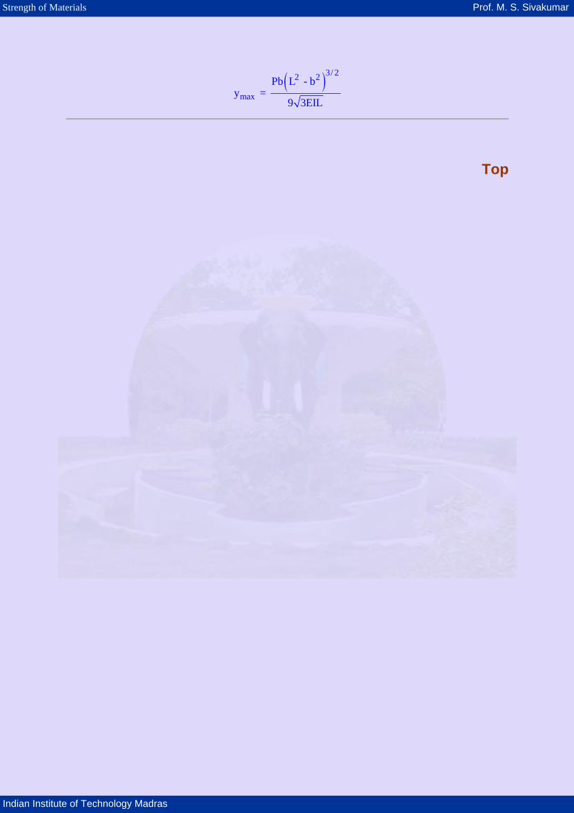
( )3/ 22 2
maxPb L - b
y = 9 3EIL
Top
Strength of Materials Prof. M. S. Sivakumar
Indian Institute of Technology Madras
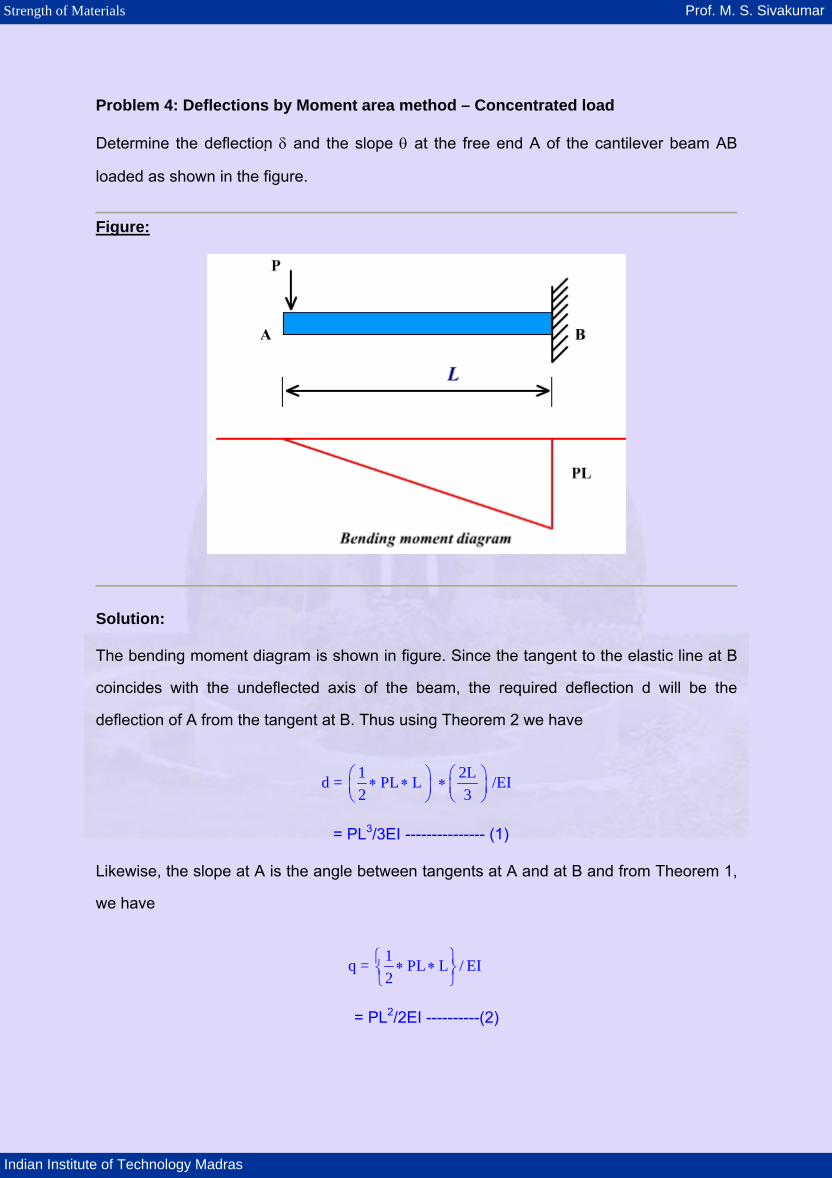
Problem 4: Deflections by Moment area method – Concentrated load
Determine the deflection δ and the slope θ at the free end A of the cantilever beam AB
loaded as shown in the figure.
Figure:
Solution:
The bending moment diagram is shown in figure. Since the tangent to the elastic line at B
coincides with the undeflected axis of the beam, the required deflection d will be the
deflection of A from the tangent at B. Thus using Theorem 2 we have
1 2d = PL L /EI2 3
⎛ ⎞ ⎛ ⎞∗ ∗ ∗⎜ ⎟ ⎜ ⎟⎝ ⎠ ⎝ ⎠
L
= PL3/3EI --------------- (1)
Likewise, the slope at A is the angle between tangents at A and at B and from Theorem 1,
we have
q = 1 PL L / EI2
⎧ ⎫∗ ∗⎨ ⎬⎩ ⎭
= PL2/2EI ----------(2)

Strength of Materials Prof. M. S. Sivakumar
Indian Institute of Technology Madras
Top

Strength of Materials Prof. M. S. Sivakumar
Indian Institute of Technology Madras
Problem 5: Deflections by Moment area method – Concentrated load
A simply supported beam AB carries a concentrated load P at point D as shown in figure.
Find the deflection d of point D from the cord line and the tangent at A.
Figure:
Solution: The bending moment diagram is shown in following figure. The area of this diagram is
Pab/2L and the distance of its centroid C from B is 1/3(L +b) as shown. Taking the statical
moment of this area with respect to point B, we obtain the deflection B'B of B away from
the tangent at A. thus
Pab L + bB'B = 2EI 3
⎛ ⎞⎜ ⎟⎝ ⎠
Strength of Materials Prof. M. S. Sivakumar
Indian Institute of Technology Madras
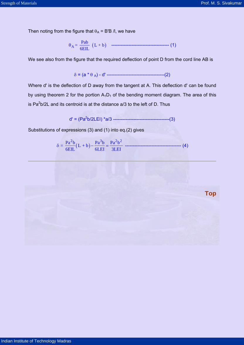
Then noting from the figure that θA = B'B /l, we have
( )APab= L + b
6EIL θ ------------------------------------- (1)
We see also from the figure that the required deflection of point D from the cord line AB is
δ = (a * θ A) - d' -------------------------------------(2)
Where d' is the deflection of D away from the tangent at A. This deflection d' can be found
by using theorem 2 for the portion A1D1 of the bending moment diagram. The area of this
is Pa2b/2L and its centroid is at the distance a/3 to the left of D. Thus
d' = (Pa2b/2LEI) *a/3 ------------------------------------(3)
Substitutions of expressions (3) and (1) into eq.(2) gives
( )2 3Pa b Pa b Pa b = L + b
6EIL 6LEI 3LEIδ − =
2 2 ------------------------------------ (4)
Top

Strength of Materials Prof. M. S. Sivakumar
Indian Institute of Technology Madras
Problem 6: Moment Area Method - udl
A prismatic cantilever beam AB carries a uniformly distributed load over the portion b of its
length as shown in the figure. Find the deflection δ of the free end A
Figure:
Solution: The bending moment diagram is shown in the figure. Its area wb3/6 from the position of its
centroid C are found by reference to the figure. Now from the second theorem the
deflection will be obtained by dividing by EI the static moment of this area with respect to
point A . Thus 1
3wb 3b= a6EI 4
⎧ ⎫δ × +⎨ ⎬⎩ ⎭
Top


![On Calculating the Slope and Deflection of a Stepped and ......“Deflection of Stepped Shafts” [2] used Castigliano’s theorem to find the deflection of a simply supported grinding](https://static.fdocuments.us/doc/165x107/60de89ff5166d82f843f5efc/on-calculating-the-slope-and-deflection-of-a-stepped-and-aoedeflection-of.jpg)