Probing Hadron Structure at CEBAF Using Polarized Electron Scattering M. Poelker, Jefferson Lab APS...
34
Probing Hadron Structure at CEBAF Using Polarized Electron Scattering M. Poelker, Jefferson Lab APS Meeting, Dallas, TX, April 2006 Structure Functions, Form Factors, Parity Violation, DVCS, GPD, more? Outline; CEBAF Overview What Can You Expect at CEBAF? Parity Violation Experiments (becoming routin New Developments for New Experiments
-
Upload
joleen-james -
Category
Documents
-
view
221 -
download
0
Transcript of Probing Hadron Structure at CEBAF Using Polarized Electron Scattering M. Poelker, Jefferson Lab APS...
Probing Hadron Structure at CEBAF Using Polarized Electron Scattering
M. Poelker, Jefferson LabAPS Meeting, Dallas, TX, April 2006
Structure Functions, Form Factors, Parity Violation, DVCS, GPD, more?
Outline; CEBAF Overview What Can You Expect at CEBAF? Parity Violation Experiments (becoming routine?) New Developments for New Experiments
AB
CA
B
C
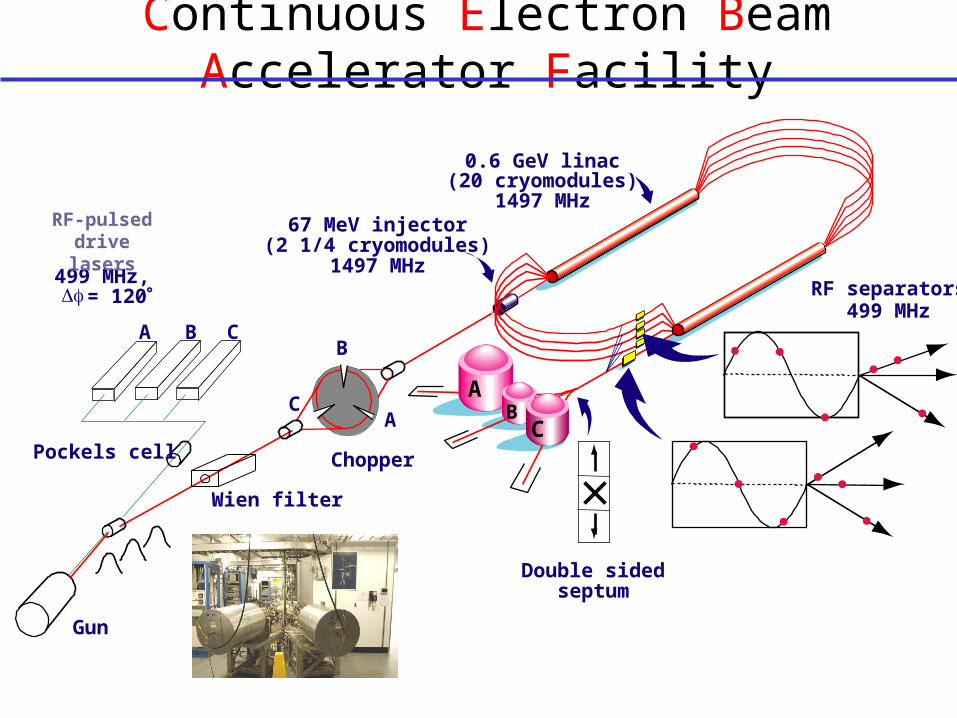
A B C
Pockels cell
Gun
0.6 GeV linac(20 cryomodules)
1497 MHz67 MeV injector
(2 1/4 cryomodules)1497 MHz
RF separators499 MHz
Double sidedseptum
499 MHz, = 120
RF-pulsed drive lasers
Wien filter
Continuous Electron Beam Accelerator Facility
Chopper
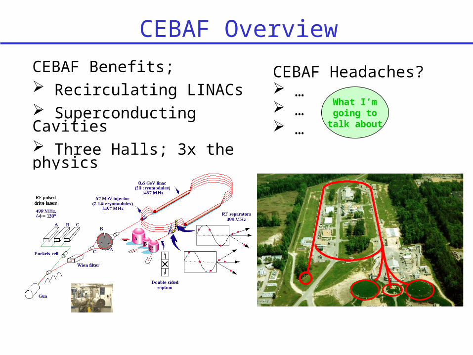
CEBAF Headaches? … … …
CEBAF Benefits; Recirculating LINACs Superconducting Cavities Three Halls; 3x the physics
CEBAF Overview
What I’m going to
talk about
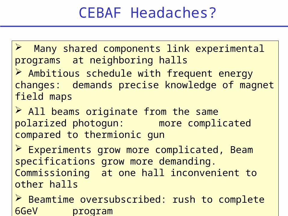
CEBAF Headaches?
Many shared components link experimental programs at neighboring halls Ambitious schedule with frequent energy changes: demands precise knowledge of magnet field maps All beams originate from the same polarized photogun: more complicated compared to thermionic gun Experiments grow more complicated, Beam specifications grow more demanding. Commissioning
at one hall inconvenient to other halls Beamtime oversubscribed: rush to complete 6GeV program
Everyone Gets Beam from Polarized Electron Gun!
CEBAF’s first polarized e-beam experiment 1997 Now polarized e-beam experiments comprise ~80% of our physics program All beams originate from the same 0.5mm spot on one photocathode inside 100kV GaAs photogun (we removed the thermionic gun in 2000) At the moment, there are three polarized e-beam
experiments on the floor;
Hall A: GEn (10uA)
Hall B: GDH (3nA)
Hall C: G0 Backward Angle (60uA)
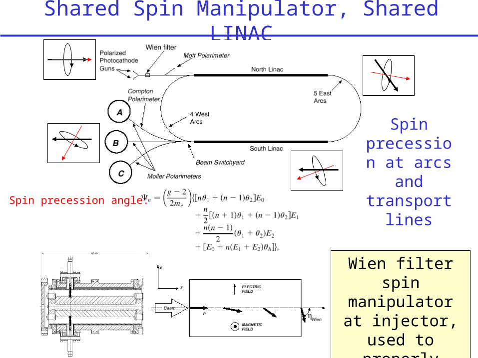
Shared Spin Manipulator, Shared LINAC
Wien filter spin manipulator at
injector, used to properly orient
spin at Hall
Spin precession at arcs and transport
linesSpin precession angle:
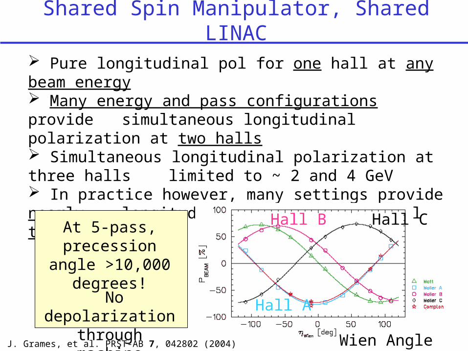
Shared Spin Manipulator, Shared LINAC
Pure longitudinal pol for one hall at any beam energy Many energy and pass configurations provide
simultaneous longitudinal polarization at two halls Simultaneous longitudinal polarization at three halls limited to ~ 2 and 4 GeV In practice however, many settings provide nearly
longitudinal polarization to all three halls
Hall A
Hall B Hall C
No depolarization
through machine
At 5-pass, precession angle
>10,000 degrees!
Wien AngleJ. Grames, et al. PRST-AB 7, 042802 (2004)
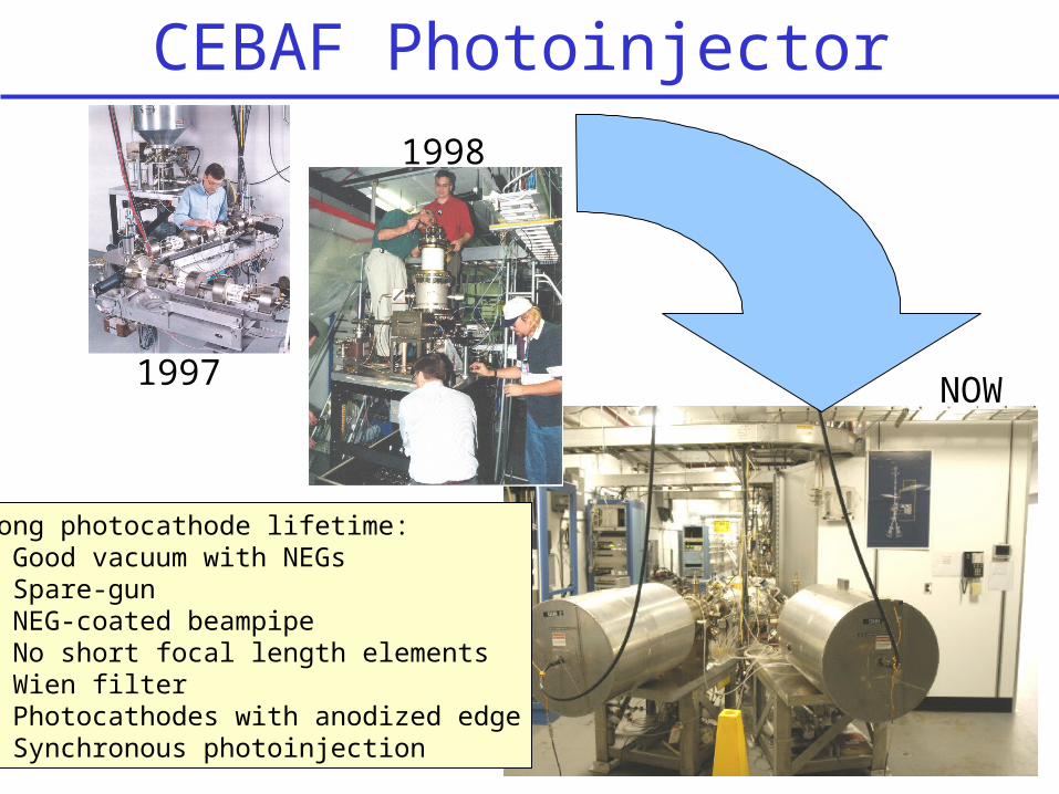
CEBAF Photoinjector
Long photocathode lifetime:• Good vacuum with NEGs• Spare-gun• NEG-coated beampipe• No short focal length elements• Wien filter• Photocathodes with anodized edge• Synchronous photoinjection
1997
1998
NOW
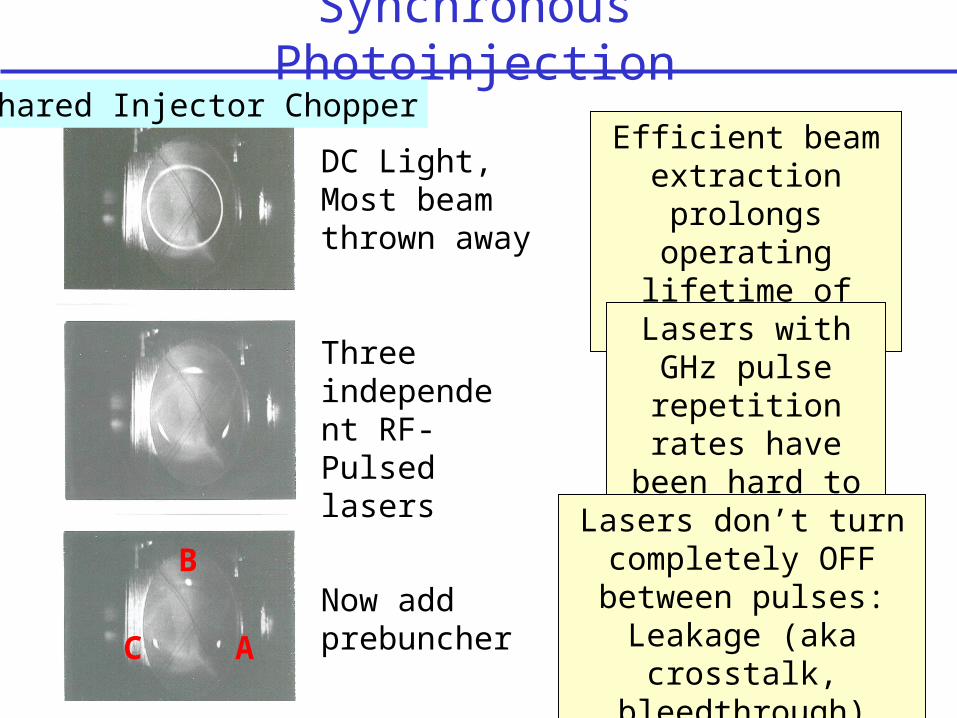
Synchronous Photoinjection
DC Light, Most beam thrown away
Three independent RF-Pulsed lasers
Now add prebuncher
Shared Injector Chopper
A
B
C
Efficient beam extraction prolongs
operating lifetime of photogun.
Lasers with GHz pulse repetition rates have been
hard to come by
Lasers don’t turn completely OFF between pulses:
Leakage (aka crosstalk,
bleedthrough)
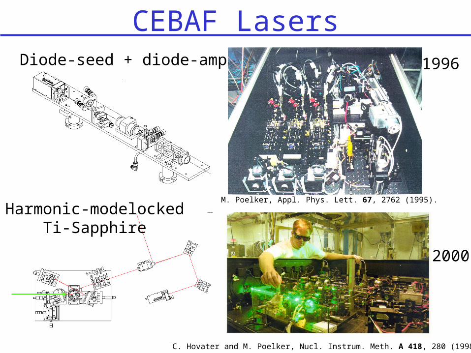
CEBAF LasersDiode-seed + diode-amp 1996
2000
Harmonic-modelocked Ti-Sapphire
M. Poelker, Appl. Phys. Lett. 67, 2762 (1995).
C. Hovater and M. Poelker, Nucl. Instrum. Meth. A 418, 280 (1998);
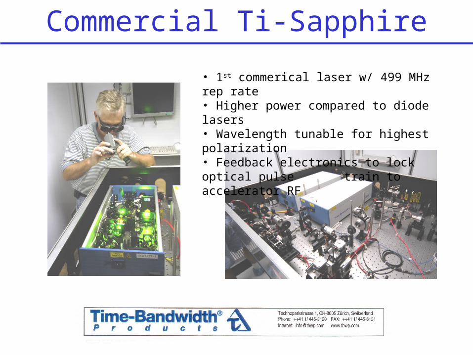
Commercial Ti-Sapphire
• 1st commerical laser w/ 499 MHz rep rate• Higher power compared to diode lasers• Wavelength tunable for highest polarization• Feedback electronics to lock optical pulse train to accelerator RF
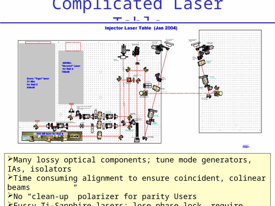
Complicated Laser Table
Many lossy optical components; tune mode generators, IAs, isolatorsTime consuming alignment to ensure coincident, colinear beamsNo “clean-up” polarizer for parity UsersFussy Ti-Sapphire lasers; lose phase lock, require weekly maintenance
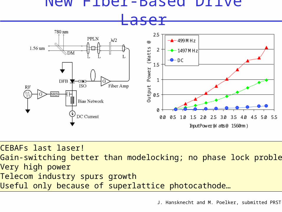
New Fiber-Based Drive Laser
CEBAFs last laser! Gain-switching better than modelocking; no phase lock problems Very high power Telecom industry spurs growth Useful only because of superlattice photocathode…
J. Hansknecht and M. Poelker, submitted PRST-AB

Other Benefits of Fiber-Based Laser?
Replace lossy laser-table components with telecom stuff?Tune mode generator (fast phase shifter and injector chopper)IA and laser attenuator: fiber amplitude modulatorFiber optic beam combiners?
Extremly good mode quality, good for parity Users?
Low repetition rate beam for particle ID and background studies, using beat frequncy method.
Polarized beam without Pockels cell?
Green version good for RF-pulsed Compton Polarimeter?
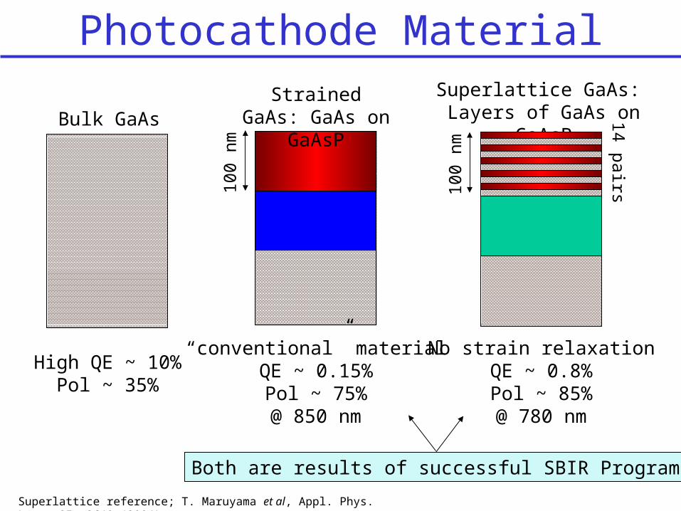
Photocathode Material
High QE ~ 10%Pol ~ 35%
Superlattice GaAs: Layers of GaAs on
GaAsPBulk GaAs
Both are results of successful SBIR Programs
“conventional” materialQE ~ 0.15%Pol ~ 75%@ 850 nm
Strained GaAs: GaAs on GaAsP
100
nm
No strain relaxationQE ~ 0.8%Pol ~ 85%@ 780 nm
100
nm
14 pairs
Superlattice reference; T. Maruyama et al, Appl. Phys. Lett. 85, 2640 (2004)
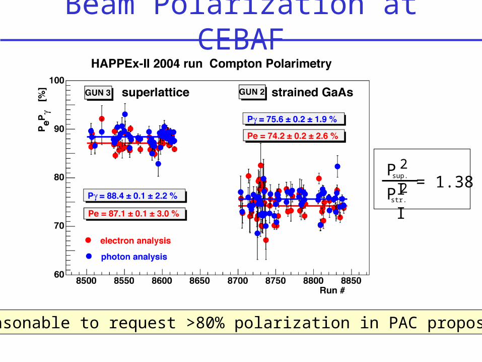
Beam Polarization at CEBAF
Reasonable to request >80% polarization in PAC proposals
P I 2
P I 2sup.
str.
= 1.38

Superlattice Photocathodes
No depolarization over time Cannot be hydrogen cleaned Arsenic-capped No solvents during preparation!
Oct 13 Nov 9QE dropped by factor of 2
Anodized edge: a critical step
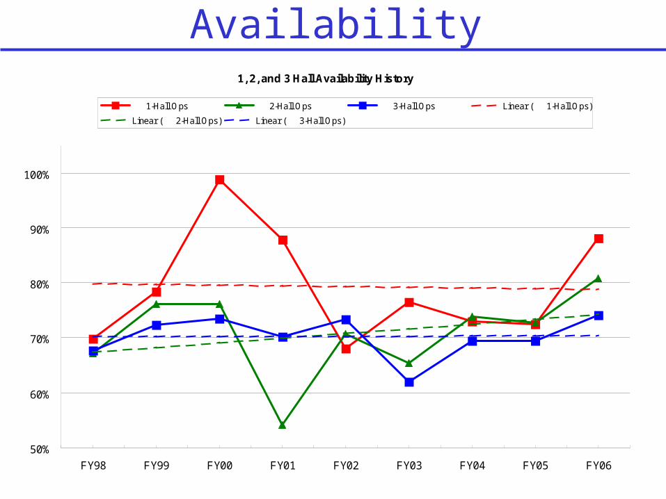
Availability1, 2, and 3 Hall Availability History
50%
60%
70%
80%
90%
100%
FY98 FY99 FY00 FY01 FY02 FY03 FY04 FY05 FY06
1-Hall Ops 2-Hall Ops 3-Hall Ops Linear ( 1-Hall Ops)
Linear ( 2-Hall Ops) Linear ( 3-Hall Ops)
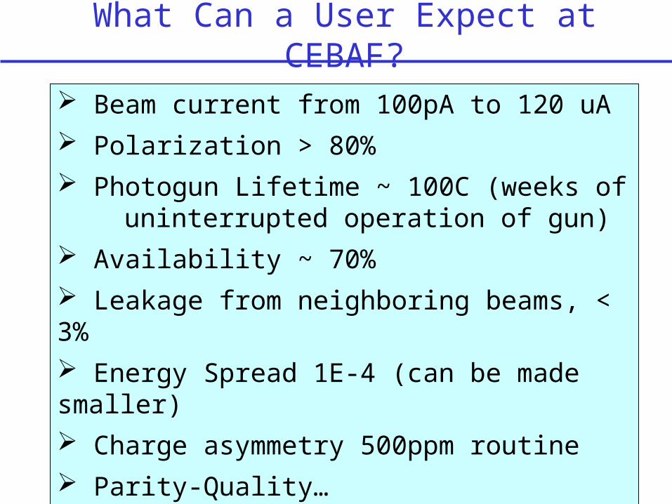
What Can a User Expect at CEBAF?
Beam current from 100pA to 120 uA Polarization > 80% Photogun Lifetime ~ 100C (weeks of uninterrupted operation of gun) Availability ~ 70% Leakage from neighboring beams, < 3% Energy Spread 1E-4 (can be made smaller) Charge asymmetry 500ppm routine Parity-Quality…
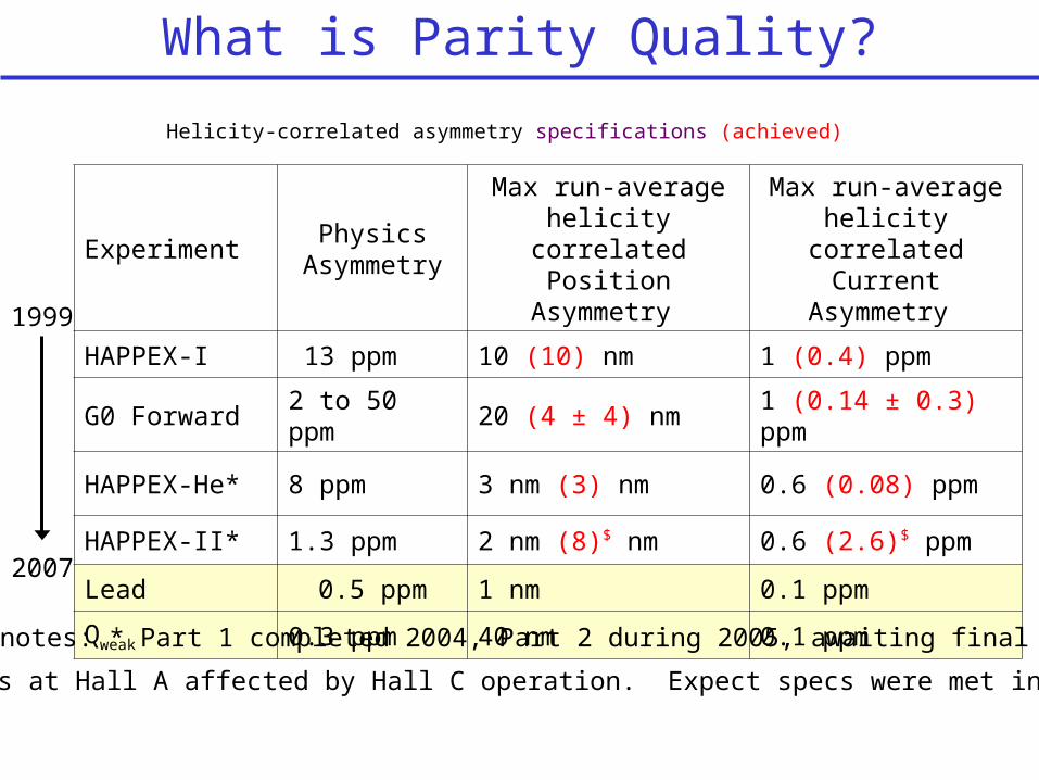
What is Parity Quality?
ExperimentPhysics
Asymmetry
Max run-average helicity correlated
Position Asymmetry
Max run-average helicity correlated
Current Asymmetry
HAPPEX-I 13 ppm 10 (10) nm 1 (0.4) ppm
G0 Forward 2 to 50 ppm 20 (4 ± 4) nm 1 (0.14 ± 0.3) ppm
HAPPEX-He* 8 ppm 3 nm (3) nm 0.6 (0.08) ppm
HAPPEX-II* 1.3 ppm 2 nm (8)$ nm 0.6 (2.6)$ ppm
Lead 0.5 ppm 1 nm 0.1 ppm
Qweak 0.3 ppm 40 nm 0.1 ppm
Helicity-correlated asymmetry specifications (achieved)
1999
2007
HAPPEx notes: * Part 1 completed 2004, Part 2 during 2005, awaiting final numbers$ Results at Hall A affected by Hall C operation. Expect specs were met in part2
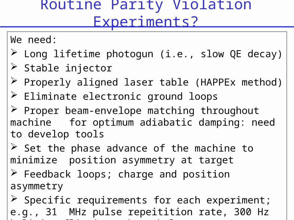
Routine Parity Violation Experiments?
We need: Long lifetime photogun (i.e., slow QE decay) Stable injector Properly aligned laser table (HAPPEx method) Eliminate electronic ground loops Proper beam-envelope matching throughout machine for optimum adiabatic damping: need to develop tools Set the phase advance of the machine to minimize
position asymmetry at target Feedback loops; charge and position asymmetry Specific requirements for each experiment; e.g., 31
MHz pulse repeitition rate, 300 Hz helicity flipping, beam halo < , etc.,
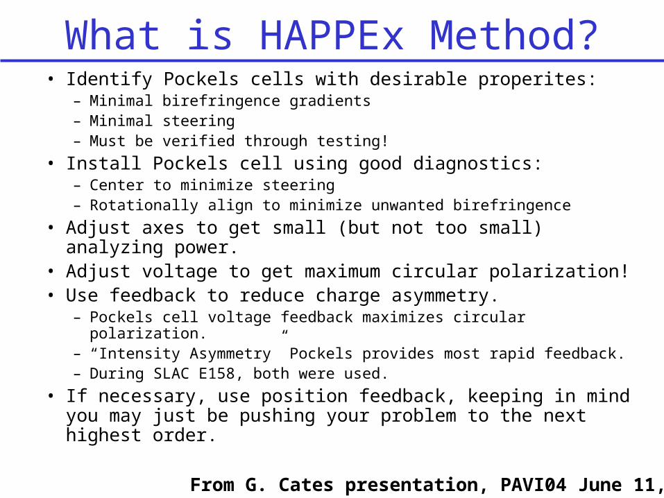
What is HAPPEx Method?• Identify Pockels cells with desirable properites:
– Minimal birefringence gradients– Minimal steering– Must be verified through testing!
• Install Pockels cell using good diagnostics:– Center to minimize steering– Rotationally align to minimize unwanted birefringence
• Adjust axes to get small (but not too small) analyzing power.• Adjust voltage to get maximum circular polarization!• Use feedback to reduce charge asymmetry.
– Pockels cell voltage feedback maximizes circular polarization.– “Intensity Asymmetry” Pockels provides most rapid feedback.– During SLAC E158, both were used.
• If necessary, use position feedback, keeping in mind you may just be pushing your problem to the next highest order.
From G. Cates presentation, PAVI04 June 11, 2004
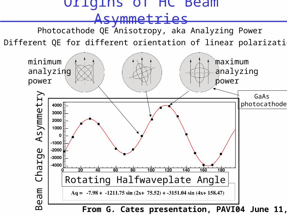
Origins of HC Beam Asymmetries
maximumanalyzingpower
minimumanalyzingpower
Bea
m C
harg
e A
sym
met
ry
Rotating Halfwaveplate Angle
Photocathode QE Anisotropy, aka Analyzing Power
Different QE for different orientation of linear polarization
GaAs photocathode
From G. Cates presentation, PAVI04 June 11, 2004
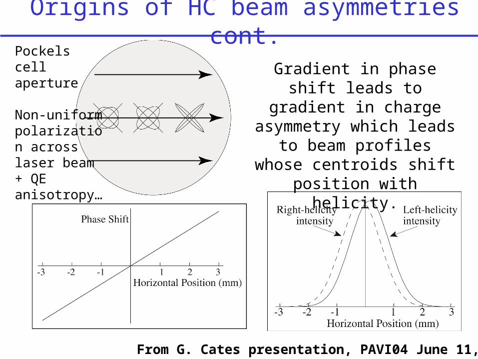
Origins of HC beam asymmetries cont.
Gradient in phase shift leads to gradient in
charge asymmetry which leads to beam profiles whose centroids shift position with helicity.
From G. Cates presentation, PAVI04 June 11, 2004
Non-uniform polarization across laser beam + QE anisotropy…
Pockels cell aperture
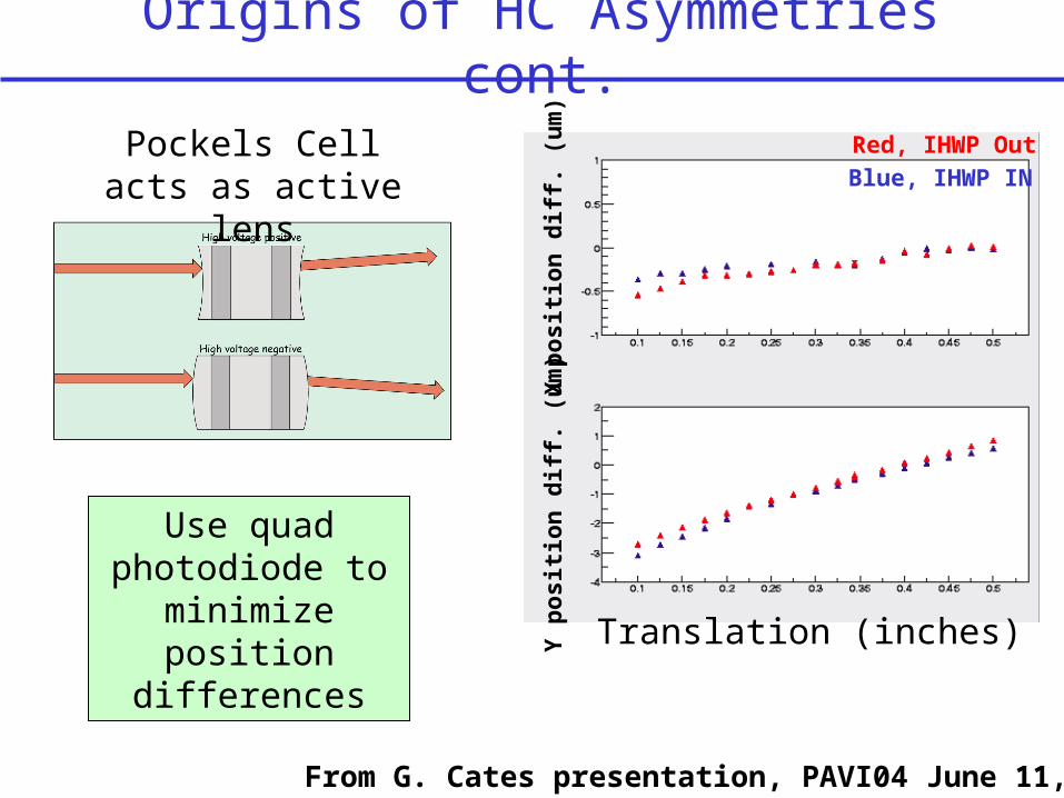
Origins of HC Asymmetries cont.
Pockels Cell acts as active lens
From G. Cates presentation, PAVI04 June 11, 2004
Translation (inches)
X p
osit
ion
dif
f. (
um
)Y
pos
itio
n d
iff.
(u
m)
Red, IHWP Out
Blue, IHWP IN
Use quad photodiode to
minimize position differences
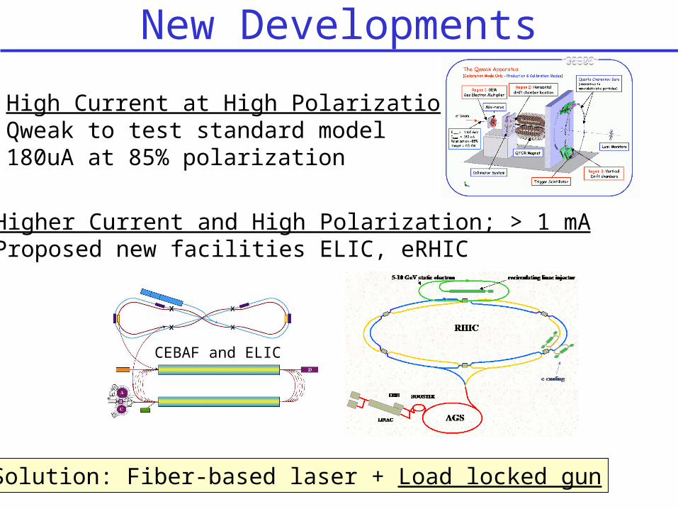
New Developments
Higher Current and High Polarization; > 1 mAProposed new facilities ELIC, eRHIC
Solution: Fiber-based laser + Load locked gun
High Current at High Polarization;Qweak to test standard model180uA at 85% polarization
CEBAF and ELIC

Test Cave LL-Gun and 100 kV Beamline
Bulk GaAs
100 kV load locked gun
Faraday CupBaked to 450C
NEG-coated large aperture beam pipe
DifferentialPumps w/ NEG’s
1W green laser, DC, 532 nm
Focusing lens on x/y stage
Spot size diagnostic
Insertable mirror
Side-view
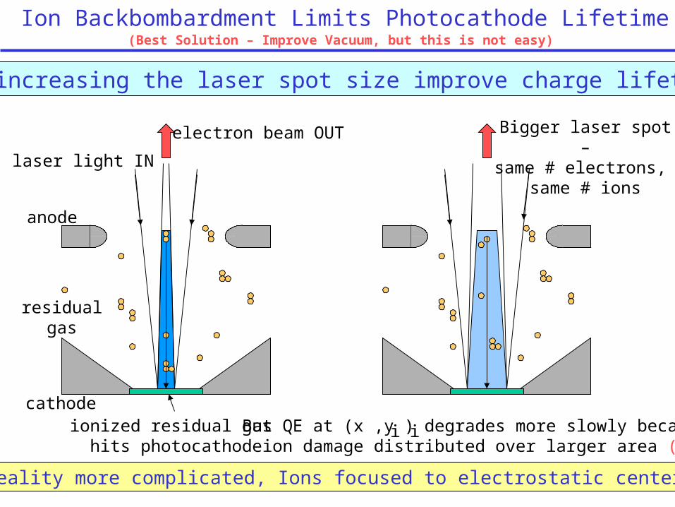
Ion Backbombardment Limits Photocathode Lifetime(Best Solution – Improve Vacuum, but this is not easy)
electron beam OUT
residual gas
cathodeionized residual gas hits photocathode
anode
laser light IN
Can increasing the laser spot size improve charge lifetime?
Bigger laser spot –same # electrons,
same # ions
But QE at (x ,y ) degrades more slowly because ion damage distributed over larger area (?)
i i
Reality more complicated, Ions focused to electrostatic center
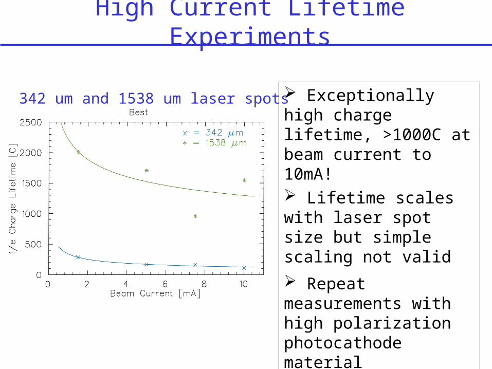
High Current Lifetime Experiments
342 um and 1538 um laser spots Exceptionally high charge lifetime, >1000C at beam current to 10mA! Lifetime scales with laser spot size but simple scaling not valid
Repeat measurements with high polarization photocathode material
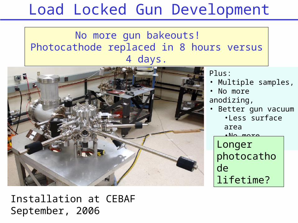
Load Locked Gun Development
No more gun bakeouts! Photocathode replaced in 8 hours versus 4
days.
Installation at CEBAF September, 2006
Plus: • Multiple samples,• No more anodizing,• Better gun vacuum
•Less surface area•No more venting
Longer photocathode lifetime?

Beat Frequency TechniqueNormal Ops;
Three beams at 499 MHzBeat Frequency Technique;One laser at 467.8125 MHz
Halls receives Low Rep Rate Beam at Beat Frequency between Laser and Chopper RF, in this case, 31.1875 MHzWhy? Particle identification, background studies
A
B
C
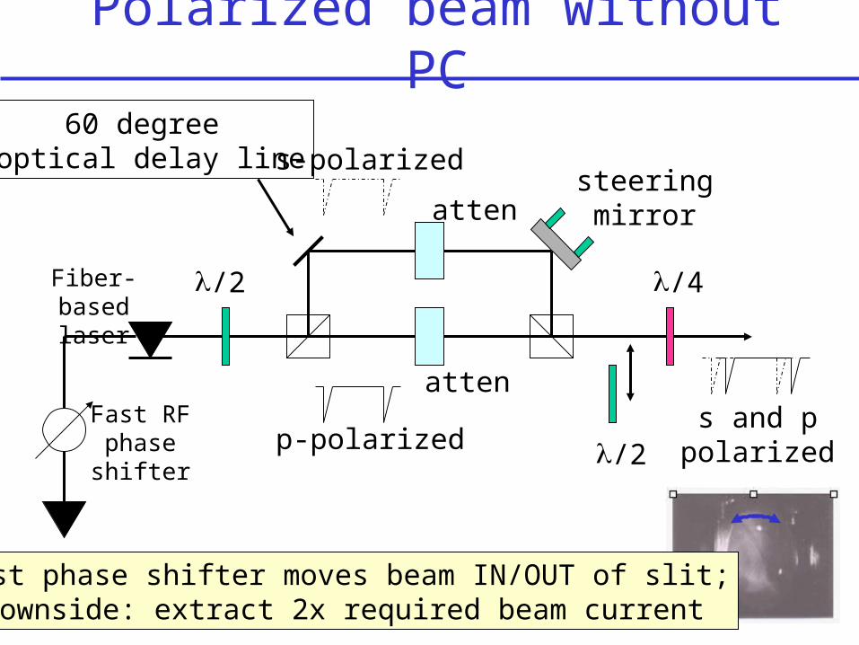
Polarized beam without PC
Fast RF phase shifter
/2
/2
/4
atten
attensteering mirror
Fiber-based laser
p-polarized
s-polarized
s and ppolarized
60 degree optical delay line
Fast phase shifter moves beam IN/OUT of slit;Downside: extract 2x required beam current
CEBAF Headaches not so bad
Healthy polarized beam program at CEBAF with (mostly) happy Users. Easy to satisfy ~60uA experiments. 100uA beam experiments at high polarization still keep us on our toes (i.e., we have to provide photocathode maintenence 1/mo.). Ongoing gun and laser development to support high current Ops. Parity violation experiments are not yet “routine” but we are getting there. Experience helps, new tools are being developed, better hardwareFiber laser and load locked gun will help a great dealWe’ve enjoyed a great relationship with our Users, hopefully Users feel simialrly about CEBAF accelerator staff.
Routine Parity Violation Experiments
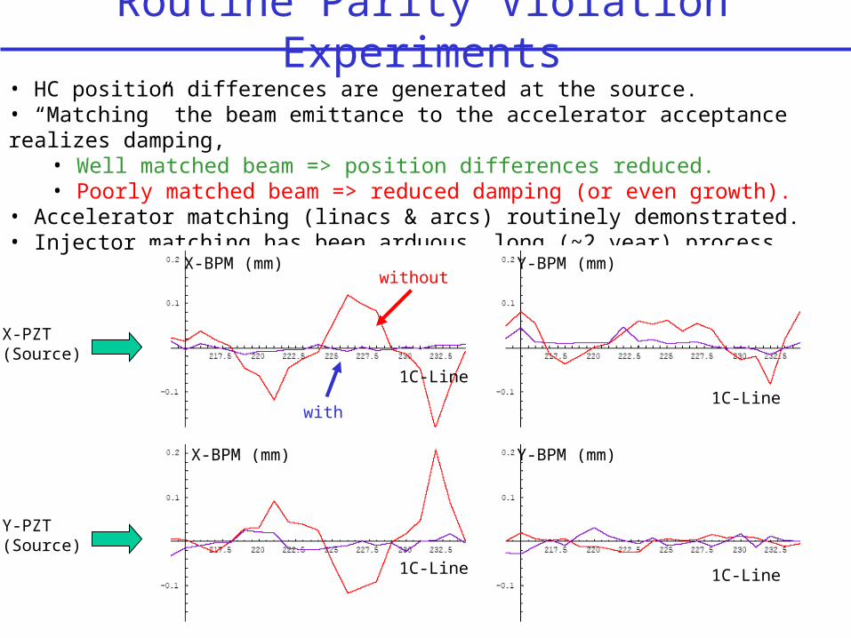
• HC position differences are generated at the source.• “Matching” the beam emittance to the accelerator acceptance realizes damping,
• Well matched beam => position differences reduced.• Poorly matched beam => reduced damping (or even growth).
• Accelerator matching (linacs & arcs) routinely demonstrated.• Injector matching has been arduous, long (~2 year) process.
X-PZT(Source)
Y-PZT(Source)
X-BPM (mm) Y-BPM (mm)
1C-Line
X-BPM (mm) Y-BPM (mm)
1C-Line
1C-Line
1C-Line
without
with