ProAxis - Frank's Hospital Workshop
143
ProAxis ® Spinal Surgery Table 6988, 6988I Owner’s Manual This manual is supplied in the following versions: English (EN) Spanish (ES) French (FR) German (DE) Italian (IT) Portuguese (PT-BR) Japanese (JA) Multilingual (ML) NW0725 Rev K MIZUHO OSI ©2016 MIZUHO OSI 30031 Ahern Avenue Union City, CA 94587-1234 Telephone: 510-429-1500 Outside USA: +1-510-429-1500 Toll Free: 800-777-4674 Fax: 510-429-8500 WWW.MIZUHOSI.COM NEWHIPNEWS.COM Emergo Europe Molenstraat 15 2513 BH The Hague The Netherlands Telephone: (31) (0) 70 345-8570 Fax: (31) (0) 70 346-7299
Transcript of ProAxis - Frank's Hospital Workshop
ProAxis®
Spinal Surgery Table
6988, 6988I
Owner’s Manual
This manual is supplied in the following versions:
English (EN)
Spanish (ES)
French (FR)
German (DE)
Italian (IT)
Portuguese (PT-BR)
Japanese (JA)
Multilingual (ML)
NW0725 Rev K
MIZUHO OSI ©2016
MIZUHO OSI
30031 Ahern Avenue
Union City, CA 94587-1234
Telephone: 510-429-1500
Outside USA: +1-510-429-1500
Toll Free: 800-777-4674
Fax: 510-429-8500
WWW.MIZUHOSI.COM
NEWHIPNEWS.COM
Emergo Europe
Molenstraat 15
2513 BH The Hague
The Netherlands
Telephone: (31) (0) 70 345-8570
Fax: (31) (0) 70 346-7299
i
Table of Contents
1 Important Notices ................................................................................................................ 1
1.1 Trademarks and Patents ......................................................................................................... 5
1.2 Disposal of Electrical Components ........................................................................................ 5
2 Introduction ........................................................................................................................ 6
2.1 General Description ................................................................................................................. 6
2.2 Intended Use ............................................................................................................................. 7
2.3 User Profile ............................................................................................................................... 7
2.4 Training Requirements ............................................................................................................ 7
2.5 Conditions of Use .................................................................................................................... 7
2.6 Product Lifetime ....................................................................................................................... 7
2.7 Specifications ........................................................................................................................... 8
2.8 Shipping and Storage .............................................................................................................. 9
2.9 Glossary of Terms.................................................................................................................. 10
3 Component Identification .................................................................................................12
3.1 Table Orientation .................................................................................................................... 12
3.1.1 IntelliPendant® ................................................................................................................................ 14
3.1.2 Cord Wrap ....................................................................................................................................... 14
3.1.3 Emergency Stop ............................................................................................................................. 14
3.1.4 Auxiliary Control Panel .................................................................................................................. 15
3.1.5 Advanced Control Pad System™ .................................................................................................. 15
3.2 Storage Cart ............................................................................................................................ 16
3.3 Component Part Number ...................................................................................................... 17
3.4 Model Number and Serial Number ....................................................................................... 18
4 Basic Operation .................................................................................................................19
4.1 Control Operation .................................................................................................................. 19
4.2 Emergency Stop ..................................................................................................................... 20
4.3 Auxiliary Control Panel ......................................................................................................... 20
4.4 Floor Locks ............................................................................................................................. 21
4.4.1 IntelliPendant® Activated Floor Lock Override ............................................................................ 22
4.4.2 Manual Floor Lock Override .......................................................................................................... 22
4.5 Moving the Table .................................................................................................................... 22
4.6 Torso Trolley® ......................................................................................................................... 23
4.7 IntelliPendant® ........................................................................................................................ 23
ii
4.7.1 Table Functions .............................................................................................................................. 26
4.7.2 Defined Function and Setting Symbols ........................................................................................ 27
4.7.3 Return to Level ............................................................................................................................... 30
4.7.4 Soft Keys Functions and Settings ................................................................................................ 30
4.7.5 Configuration of Table for Transport or Storage ......................................................................... 38
4.7.6 Version Info ..................................................................................................................................... 47
4.8 Independent Monitoring System (IMS) ................................................................................ 47
5 Inspection ..........................................................................................................................49
5.1 Acceptance and Transfer ...................................................................................................... 49
5.2 Pre-Procedure/Post-Procedure ............................................................................................ 49
5.3 Semi-Annual Preventative Maintenance .............................................................................. 49
5.4 Product Lifetime ..................................................................................................................... 49
6 Function Check .................................................................................................................50
7 ProAxis® Spinal Surgery Table Standard Components ..................................................54
7.1 ProAxis® Standard Components .......................................................................................... 54
7.2 ProAxis® Patient Care Kits .................................................................................................... 56
8 Setup of ProAxis® Spinal Surgery Table for Surgical Procedures .................................57
8.1 ProAxis® Prone Patient Positioning ..................................................................................... 59
8.1.1 Components Used for Prone Patient Positioning ........................................................................ 79
8.2 ProAxis® Prone Patient Positioning with Cervical Management ...................................... 82
8.2.1 Prone Positioning with Cervical Management Base Unit ............................................................ 82
8.2.2 Prone Patient Positioning with Cervical Traction Vector Adjustor ............................................ 91
8.2.3 Components for Prone Patient Positioning with Cervical Accessories .................................... 93
8.3 ProAxis® Supine Patient Positioning ................................................................................... 95
8.3.1 Components Used for Supine Patient Positioning .................................................................... 102
8.3.2 Supine Patient Positioning with Cervical Traction Vector Adjustor ........................................ 103
8.3.3 Components for Supine Patient Positioning with Cervical Accessories ................................. 104
8.4 ProAxis® Lateral Patient Positioning ................................................................................. 105
8.4.1 Components Used for Lateral Patient Positioning .................................................................... 109
9 ProAxis® Optional Accessories ...................................................................................... 110
10 Cleaning, Storage, and Maintenance ............................................................................. 112
10.1 Cleaning and Disinfecting ................................................................................................. 112
10.1.1 Table Exterior .............................................................................................................................. 112
10.1.2 ProneView® Helmet and Mirror System .................................................................................... 112
iii
10.1.3 Mizuho OSI Tempur-Pedic® Medical Pads ................................................................................ 113
10.2 Storage ................................................................................................................................ 113
10.3 Maintenance ....................................................................................................................... 113
11 Software Troubleshooting .............................................................................................. 115
11.1 Software Release Notes .................................................................................................... 122
11.1.1 Software Version 1.105 .............................................................................................................. 122
11.1.2 Software Version 1.110 .............................................................................................................. 123
11.1.3 Software Version 1.111 .............................................................................................................. 124
11.2 Manual Floor Lock Override ............................................................................................. 125
12 Electrical System ............................................................................................................ 127
12.1 Description ......................................................................................................................... 127
12.2 Component Identification and Function .......................................................................... 127
12.2.1 Detachable Power Cord ............................................................................................................. 127
12.2.2 Power Switch .............................................................................................................................. 127
12.2.3 Power/Charging Indicator .......................................................................................................... 127
12.2.4 Circuit Breakers .......................................................................................................................... 128
12.2.5 The Emergency Stop Button ..................................................................................................... 128
12.2.6 IntelliPendant® ............................................................................................................................ 128
12.3 Battery System ................................................................................................................... 128
12.3.1 Charging the Batteries ............................................................................................................... 129
12.3.2 Replacing the Batteries .............................................................................................................. 129
12.3.3 Lithium Battery ........................................................................................................................... 133
13 Technical Support ........................................................................................................... 134
13.1 Contact for Parts and Service ........................................................................................... 134
13.2 Further Technical Information .......................................................................................... 134
13.3 Order Replacement Parts .................................................................................................. 134
13.4 Return Damaged Parts ...................................................................................................... 134
13.5 Send a Part for Repair ....................................................................................................... 135
13.6 Warranty .............................................................................................................................. 135
13.7 European Union EC Representative ................................................................. 135
14 Appendix .......................................................................................................................... 136
14.1 Electromagnetic Emissions .............................................................................................. 136
14.2 Electromagnetic Immunity ................................................................................................ 137
14.3 Recommended Separation Distances.............................................................................. 139
ProAxis® Spinal Surgery Table Owner’s Manual
1 Mizuho OSI 2016 NW0725 Rev K
1 Important Notices
CAUTION: To ensure safe operation of the equipment, please READ THESE INSTRUCTIONS COMPLETELY and keep this manual readily available for future reference.
Carefully observe and comply with all warnings, cautions and instructions placed on the equipment or described in this manual.
NOTE: This device is intended for use by trained personnel only. To schedule an in-service, please contact your domestic Mizuho OSI sales representative or call 1-800-777-4674 within the USA or +1-510-429-1500 outside the USA.
NOTE: The application techniques outlined in these instructions are the manufacturer’s suggested techniques. The final disposition of each patient’s care as related to the use of this equipment rests with the attending surgeon.
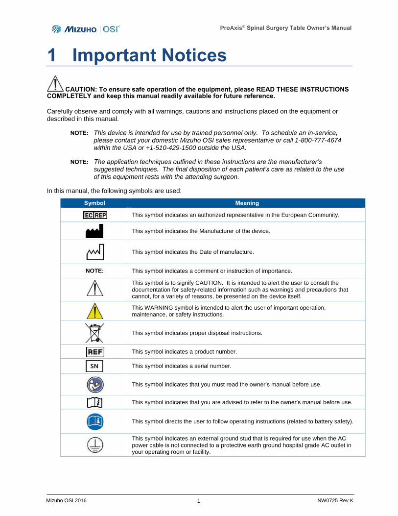
In this manual, the following symbols are used:
Symbol Meaning
This symbol indicates an authorized representative in the European Community.
This symbol indicates the Manufacturer of the device.
This symbol indicates the Date of manufacture.
NOTE: This symbol indicates a comment or instruction of importance.
This symbol is to signify CAUTION. It is intended to alert the user to consult the documentation for safety-related information such as warnings and precautions that cannot, for a variety of reasons, be presented on the device itself.
This WARNING symbol is intended to alert the user of important operation, maintenance, or safety instructions.
This symbol indicates proper disposal instructions.
This symbol indicates a product number.
This symbol indicates a serial number.
This symbol indicates that you must read the owner’s manual before use.
This symbol indicates that you are advised to refer to the owner’s manual before use.
This symbol directs the user to follow operating instructions (related to battery safety).
This symbol indicates an external ground stud that is required for use when the AC power cable is not connected to a protective earth ground hospital grade AC outlet in your operating room or facility.
ProAxis® Spinal Surgery Table Owner’s Manual
2 Mizuho OSI 2016 NW0725 Rev K
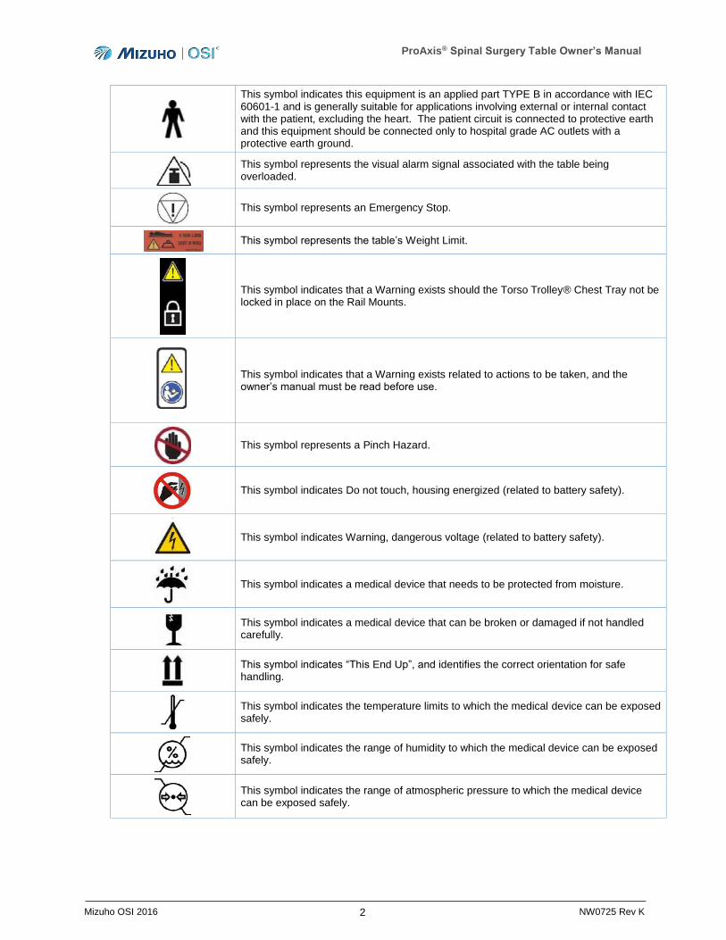
This symbol indicates this equipment is an applied part TYPE B in accordance with IEC 60601-1 and is generally suitable for applications involving external or internal contact with the patient, excluding the heart. The patient circuit is connected to protective earth and this equipment should be connected only to hospital grade AC outlets with a protective earth ground.
This symbol represents the visual alarm signal associated with the table being overloaded.
This symbol represents an Emergency Stop.
This symbol represents the table’s Weight Limit.
This symbol indicates that a Warning exists should the Torso Trolley® Chest Tray not be locked in place on the Rail Mounts.
This symbol indicates that a Warning exists related to actions to be taken, and the owner’s manual must be read before use.
This symbol represents a Pinch Hazard.
This symbol indicates Do not touch, housing energized (related to battery safety).
This symbol indicates Warning, dangerous voltage (related to battery safety).
This symbol indicates a medical device that needs to be protected from moisture.
This symbol indicates a medical device that can be broken or damaged if not handled carefully.
This symbol indicates “This End Up”, and identifies the correct orientation for safe handling.
This symbol indicates the temperature limits to which the medical device can be exposed safely.
This symbol indicates the range of humidity to which the medical device can be exposed safely.
This symbol indicates the range of atmospheric pressure to which the medical device can be exposed safely.
ProAxis® Spinal Surgery Table Owner’s Manual
3 Mizuho OSI 2016 NW0725 Rev K
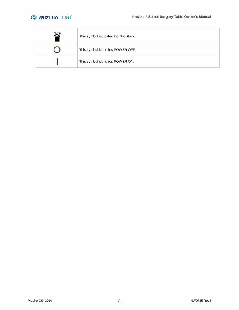
This symbol indicates Do Not Stack.
This symbol identifies POWER OFF.
This symbol identifies POWER ON.

ProAxis® Spinal Surgery Table Owner’s Manual
4 Mizuho OSI 2016 NW0725 Rev K
WARNING: Proper preoperative and intra-operative procedures must be followed to prevent venous stasis and pooling, pressure sore development, neuropathy, improper electro-surgical tissue grounding, hypertension/hypotension, and hypothermia.
WARNING: To avoid the risk of electric shock, this equipment must only be connected to a supply mains with protective earth.
WARNING: The ProAxis® Table is to be used by personnel that receive training from either Mizuho OSI or from someone qualified by the medical facility to provide this training. Failure to comply with this requirement may result in damage to the table, possible injury to the patient or harm to the healthcare workers.
WARNING: This symbol indicates an external ground stud that is required for use when the AC power cable is not connected to a protective earth ground hospital grade AC outlet in your operating room or facility. To protect the patient, hospital staff, and the device from possible electrical hazards, an external ground wire connection is required between the external ground stud and protective earth ground when the device is in use under battery power or not connected to a protective earth ground.
WARNING: Medical electrical equipment needs special precautions regarding EMC and needs to be installed and put into service according to the EMC information provided in this manual.
WARNING: Use of the ProAxis® Spinal Surgery Table with patients weighing more than 500 lbs (227 kg) could result in damage to the table, possible injury to the patient, or harm to the healthcare professional.
WARNING: When unlatching the spars from the Head-End of the ProAxis® Spinal Surgery Table for either storage or cleaning, do not use excessive force to unlatch the spars. If after unlocking the spar lock, the spar does not unlatch with hand force, seek assistance from qualified service personnel. Failure to properly unlatch the spars may cause harm to the healthcare professional and/or the device.
WARNING: Before and after each use, inspect the table, components and accessories for possible damage, excessive wear, or non-functioning parts. Carefully inspect all accessible areas, joints, and all moving parts for possible damage or non-function. Damaged or defective parts should not be used or processed. Contact Mizuho OSI Services for repair or replacement (refer to Section 13).
WARNING: The ProAxis® Spinal Surgery Table should not be operated in an oxygen-rich environment nor in the presence of flammable anesthetics, volatile substances, or other explosive gases, liquids, or atmospheres.
WARNING: No modification of the ProAxis® Spinal Surgery Table or its components is
ProAxis® Spinal Surgery Table Owner’s Manual
5 Mizuho OSI 2016 NW0725 Rev K
allowed. Any modification to the equipment may result in damage to the table, possible injury to the patient or harm to the healthcare professionals.
CAUTION: As outlined in the AORN Recommended Practices for Positioning a Patient in the Perioperative Setting, following the positioning of the patient, an assessment of the patient’s alignment, tissue perfusion, and skin integrity should be completed. All contact points of the patient with the table pads should be monitored during the procedure.
NOTE: If the integrity of the AC power source is in doubt, the equipment shall be operated from its internal electrical power source (battery).
NOTE: If high-frequency surgical equipment, cardiac defibrillators or cardiac defibrillator monitors are to be used with the ProAxis® Spinal Surgery Table, refer to the instructions for use provided by the manufacturer of those devices.
1.1 Trademarks and Patents
ProAxis®, IntelliPendant®, Torso Trolley®, GentleTouch®, ShearGuard®, and Orange Aid® are registered trademarks of Mizuho OSI.
Advanced Control Pad System™ is a trademark of Mizuho OSI.
DORO® is a registered trademark of pro med instruments GmbH.
Mayfield® is a registered trademark of Schaerer Mayfield USA, Inc.
O-arm® is a registered trademark of Medtronic, Inc.
ProneView® is a registered trademark of Dupaco, Inc.
Tempur-Pedic® is a registered trademark of Tempur-Pedic North America, Inc.
Velcro® is a registered trademark of Velcro Industries.
Product protected by:
US Patent Number: 8,584,281
(Other patents pending)
1.2 Disposal of Electrical Components
In accordance with the European Union Waste Electrical and Electronic Equipment (WEEE) Directive, all electrical components and batteries must be disposed of in accordance with local regulations or returned to Mizuho OSI for proper disposal. Please contact Mizuho OSI Services at 1-800-777-4674 within the USA or +1-510-429-1500 outside the USA for further information regarding this requirement.
ProAxis® Spinal Surgery Table Owner’s Manual
6 Mizuho OSI 2016 NW0725 Rev K
2 Introduction
2.1 General Description
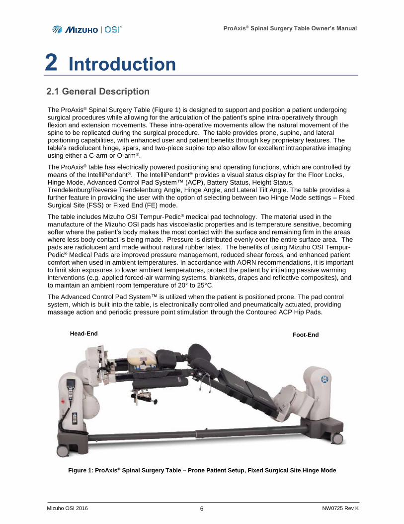
The ProAxis® Spinal Surgery Table (Figure 1) is designed to support and position a patient undergoing surgical procedures while allowing for the articulation of the patient’s spine intra-operatively through flexion and extension movements. These intra-operative movements allow the natural movement of the spine to be replicated during the surgical procedure. The table provides prone, supine, and lateral positioning capabilities, with enhanced user and patient benefits through key proprietary features. The table’s radiolucent hinge, spars, and two-piece supine top also allow for excellent intraoperative imaging using either a C-arm or O-arm®.
The ProAxis® table has electrically powered positioning and operating functions, which are controlled by means of the IntelliPendant®. The IntelliPendant® provides a visual status display for the Floor Locks, Hinge Mode, Advanced Control Pad System™ (ACP), Battery Status, Height Status, Trendelenburg/Reverse Trendelenburg Angle, Hinge Angle, and Lateral Tilt Angle. The table provides a further feature in providing the user with the option of selecting between two Hinge Mode settings – Fixed Surgical Site (FSS) or Fixed End (FE) mode.
The table includes Mizuho OSI Tempur-Pedic® medical pad technology. The material used in the manufacture of the Mizuho OSI pads has viscoelastic properties and is temperature sensitive, becoming softer where the patient’s body makes the most contact with the surface and remaining firm in the areas where less body contact is being made. Pressure is distributed evenly over the entire surface area. The pads are radiolucent and made without natural rubber latex. The benefits of using Mizuho OSI Tempur-Pedic® Medical Pads are improved pressure management, reduced shear forces, and enhanced patient comfort when used in ambient temperatures. In accordance with AORN recommendations, it is important to limit skin exposures to lower ambient temperatures, protect the patient by initiating passive warming interventions (e.g. applied forced-air warming systems, blankets, drapes and reflective composites), and to maintain an ambient room temperature of 20° to 25°C.
The Advanced Control Pad System™ is utilized when the patient is positioned prone. The pad control system, which is built into the table, is electronically controlled and pneumatically actuated, providing massage action and periodic pressure point stimulation through the Contoured ACP Hip Pads.
Figure 1: ProAxis® Spinal Surgery Table – Prone Patient Setup, Fixed Surgical Site Hinge Mode
Foot-End Head-End
ProAxis® Spinal Surgery Table Owner’s Manual
7 Mizuho OSI 2016 NW0725 Rev K
2.2 Intended Use
The ProAxis® Spinal Surgery Table is a mobile, dual-column, carbon-fiber hinged frame surgery table designed for temporary support (<24 hours) and positioning of a patient in a prone, supine, or lateral position. The table is intended for use during surgical procedures, including radiographic imaging during such procedures. The table is not intended for use in patient transport.
ProAxis® provides a platform designed to support and position adult and pediatric patients with body weight less than 500 pounds (227 kg) that fall within the height range of 58-81 inches (147-206 cm).
The ProAxis® system, when used with the Torso Trolley® Chest Pad and the Contoured Hip Pads, shall support patients in a prone position with minimal iliac crest to iliac crest distances of 8.0 inches (20.3 cm).
2.3 User Profile
The ProAxis® Spinal Surgery Table is suitable for use by health care professionals, including but not limited to surgeons, radiologists, anesthesiologists, circulating nurses, surgical technicians, biomedical technicians, and radiology technicians.
2.4 Training Requirements
Before using the ProAxis® Spinal Surgery Table, the user must read this ProAxis® Spinal Surgery Table Owner’s Manual ( NW0725).
It is required that personnel using the ProAxis® Spinal Surgery Table receive training by either Mizuho OSI or by someone qualified by the medical facility to provide this training.
WARNING: Failure to ensure training prior to use of this device may cause harm to the patient, healthcare professional, or the device.
2.5 Conditions of Use
The ProAxis® Spinal Surgery Table may be used several times throughout the day and night in medical facilities; e.g. hospitals, and outpatient surgery/imaging centers. The ProAxis® Spinal Surgery Table will be used in an operating room or other treatment room, and may be rolled between rooms. It shall not be used for patient transport.
WARNING: To maximize patient safety, do not move the table with surgical equipment in vivo that is not free to move with the patient.
2.6 Product Lifetime
The product’s service lifetime is defined as 10 years. At the time of delivery, your product fulfills existing regulations and standards. However, despite proper use, routine inspection, prescribed service, maintenance and repairs, the product is subject to aging and wear. Therefore, Mizuho OSI cannot guarantee the product’s safety after ten (10) years and recommends your product be taken out of service. For product warranty information, refer to Section 13 of this manual.
ProAxis® Spinal Surgery Table Owner’s Manual
8 Mizuho OSI 2016 NW0725 Rev K
2.7 Specifications
The ProAxis® Spinal Surgery Table has the following specifications:
The maximum patient load is 500 pounds (227 kg) in a procedural position at any point within its physical range.
The patient height range supported by the table is 58-81 inches (147-206 cm).
Table top width: o The open frame used for prone positioning is 19 inches (48 cm). o The Supine Tops used for supine and lateral positioning are 21 inches (53 cm).
Table top length is 81 inches (206 cm).
When in use, the overall length of the table is 122-138 inches (310 - 351 cm) dependent on where the table is in its range of movements.
The table can be configured to a length of 80 inches (204 cm) for storage (Figure 55, page 46).
Defined Home position: Height of 32 inches (81 cm) top of hinged frame to floor with a level table top (i.e. 0° Hinge, Tilt, and Trendelenburg/Reverse Trendelenburg).
Height Range: 20 inches – 47 inches (51 cm – 119 cm) when table top is Level.
Lateral Tilt (left/right) is 0 – 15 degrees.
Trendelenburg is 0 – 15 degrees from the Home position
Reverse Trendelenburg is 0 – 20 degrees from the Home position
Two Hinge Modes: Fixed Surgical Site (FSS), Fixed End (FE)
Hinge Angle Range: -20 to +35 degrees o Some height adjustments may be required to achieve the maximum hinge up angle in
FSS only. o Some height adjustments may be required to achieve the minimum hinge down angle.
The table trapezoidal rail frame and Supine Tops are made of radiolucent carbon-fiber construction.
Input power requirement is 100/120V, 50/60 Hz ( 6988) or 220/240V, 50/60 Hz ( 6988I) as indicated on the manufacturer’s label.
As a back-up power source, the table may be operated under battery power. The expected working life of a fully charged battery is approximately eight (8) hours with two procedures averaging six (6) minutes of motion time.
The table is IPX4 rated per IEC 60529.
Operating environment: +50 to +86 degrees F (+10 to +30 degrees C), relative humidity 40%-70%.
Class 1 Equipment, Type B per IEC 60601-1.
The table is not suitable for use with flammable anesthetic gas mixtures.
ProAxis® Spinal Surgery Table Owner’s Manual
9 Mizuho OSI 2016 NW0725 Rev K
2.8 Shipping and Storage
If required to be transported, the ProAxis® Spinal Surgery Table must be transported using the appropriate shipping crate. Unpacking instructions are included with the original shipping crate.
When not in use, the ProAxis® Spinal Surgery Table should be stored in a clean, dry environment.
The following conditions are required of the shipping and or storage environment:
Ambient temperature -4°F (-20°C) to 122°F (50°C)
Relative humidity from 10% to 95%, non-condensing
Atmospheric pressure from 75 to 105 kPa
To prepare the table to be shipped or stored in a more compact configuration, utilize the IntelliPendant® and complete the steps outlined (Section 4.7.5). Transporting or storing the table in the stored configuration reduces the length of the table from 122 inches (310 cm) to 80 inches (204 cm).
When in storage, the table cover provided serves as a dust cover and should be used. The table cover can be adjusted with the Velcro® closures so it will fit the ProAxis® in the standard use table position (fully extended) or stored configuration (reduced length). Also, to ensure that the battery is always fully charged and ready for use, store the table connected to AC power that matches the ratings on the manufacturer’s label, located on the Foot-End column (Figure 10, page 18).
ProAxis® Spinal Surgery Table Owner’s Manual
10 Mizuho OSI 2016 NW0725 Rev K
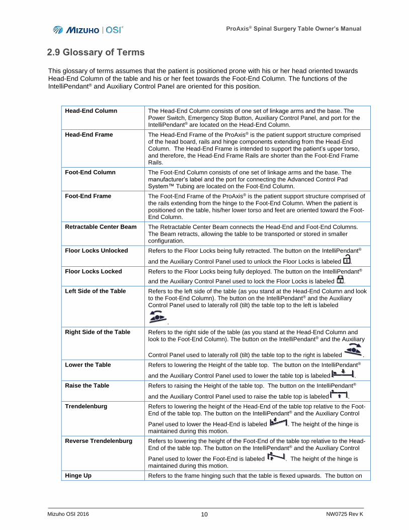
2.9 Glossary of Terms
This glossary of terms assumes that the patient is positioned prone with his or her head oriented towards Head-End Column of the table and his or her feet towards the Foot-End Column. The functions of the IntelliPendant® and Auxiliary Control Panel are oriented for this position.
Head-End Column The Head-End Column consists of one set of linkage arms and the base. The Power Switch, Emergency Stop Button, Auxiliary Control Panel, and port for the IntelliPendant® are located on the Head-End Column.
Head-End Frame The Head-End Frame of the ProAxis® is the patient support structure comprised of the head board, rails and hinge components extending from the Head-End Column. The Head-End Frame is intended to support the patient’s upper torso, and therefore, the Head-End Frame Rails are shorter than the Foot-End Frame Rails.
Foot-End Column The Foot-End Column consists of one set of linkage arms and the base. The manufacturer’s label and the port for connecting the Advanced Control Pad System™ Tubing are located on the Foot-End Column.
Foot-End Frame The Foot-End Frame of the ProAxis® is the patient support structure comprised of the rails extending from the hinge to the Foot-End Column. When the patient is positioned on the table, his/her lower torso and feet are oriented toward the Foot- End Column.
Retractable Center Beam The Retractable Center Beam connects the Head-End and Foot-End Columns. The Beam retracts, allowing the table to be transported or stored in smaller configuration.
Floor Locks Unlocked Refers to the Floor Locks being fully retracted. The button on the IntelliPendant®
and the Auxiliary Control Panel used to unlock the Floor Locks is labeled .
Floor Locks Locked Refers to the Floor Locks being fully deployed. The button on the IntelliPendant®
and the Auxiliary Control Panel used to lock the Floor Locks is labeled .
Left Side of the Table Refers to the left side of the table (as you stand at the Head-End Column and look to the Foot-End Column). The button on the IntelliPendant® and the Auxiliary Control Panel used to laterally roll (tilt) the table top to the left is labeled
.
Right Side of the Table Refers to the right side of the table (as you stand at the Head-End Column and look to the Foot-End Column). The button on the IntelliPendant® and the Auxiliary
Control Panel used to laterally roll (tilt) the table top to the right is labeled .
Lower the Table Refers to lowering the Height of the table top. The button on the IntelliPendant®
and the Auxiliary Control Panel used to lower the table top is labeled .
Raise the Table Refers to raising the Height of the table top. The button on the IntelliPendant®
and the Auxiliary Control Panel used to raise the table top is labeled .
Trendelenburg Refers to lowering the height of the Head-End of the table top relative to the Foot-End of the table top. The button on the IntelliPendant® and the Auxiliary Control
Panel used to lower the Head-End is labeled . The height of the hinge is maintained during this motion.
Reverse Trendelenburg Refers to lowering the height of the Foot-End of the table top relative to the Head-End of the table top. The button on the IntelliPendant® and the Auxiliary Control
Panel used to lower the Foot-End is labeled . The height of the hinge is maintained during this motion.
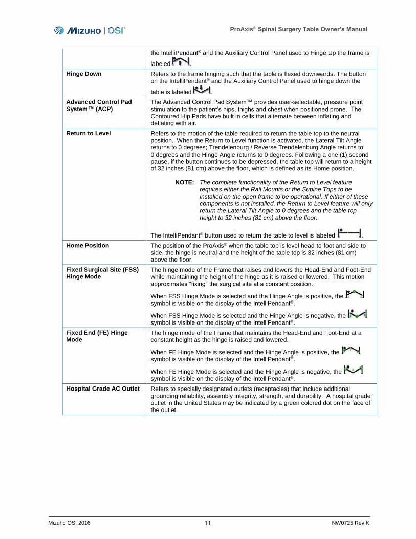
Hinge Up Refers to the frame hinging such that the table is flexed upwards. The button on
ProAxis® Spinal Surgery Table Owner’s Manual
11 Mizuho OSI 2016 NW0725 Rev K
the IntelliPendant® and the Auxiliary Control Panel used to Hinge Up the frame is
labeled .
Hinge Down Refers to the frame hinging such that the table is flexed downwards. The button on the IntelliPendant® and the Auxiliary Control Panel used to hinge down the
table is labeled .
Advanced Control Pad System™ (ACP)
The Advanced Control Pad System™ provides user-selectable, pressure point stimulation to the patient’s hips, thighs and chest when positioned prone. The Contoured Hip Pads have built in cells that alternate between inflating and deflating with air.
Return to Level Refers to the motion of the table required to return the table top to the neutral position. When the Return to Level function is activated, the Lateral Tilt Angle returns to 0 degrees; Trendelenburg / Reverse Trendelenburg Angle returns to 0 degrees and the Hinge Angle returns to 0 degrees. Following a one (1) second pause, if the button continues to be depressed, the table top will return to a height of 32 inches (81 cm) above the floor, which is defined as its Home position.
NOTE: The complete functionality of the Return to Level feature requires either the Rail Mounts or the Supine Tops to be installed on the open frame to be operational. If either of these components is not installed, the Return to Level feature will only return the Lateral Tilt Angle to 0 degrees and the table top height to 32 inches (81 cm) above the floor.
The IntelliPendant® button used to return the table to level is labeled .
Home Position The position of the ProAxis® when the table top is level head-to-foot and side-to side, the hinge is neutral and the height of the table top is 32 inches (81 cm) above the floor.
Fixed Surgical Site (FSS) Hinge Mode
The hinge mode of the Frame that raises and lowers the Head-End and Foot-End while maintaining the height of the hinge as it is raised or lowered. This motion approximates “fixing” the surgical site at a constant position.
When FSS Hinge Mode is selected and the Hinge Angle is positive, the symbol is visible on the display of the IntelliPendant®.
When FSS Hinge Mode is selected and the Hinge Angle is negative, the symbol is visible on the display of the IntelliPendant®.
Fixed End (FE) Hinge Mode
The hinge mode of the Frame that maintains the Head-End and Foot-End at a constant height as the hinge is raised and lowered.
When FE Hinge Mode is selected and the Hinge Angle is positive, the symbol is visible on the display of the IntelliPendant®.
When FE Hinge Mode is selected and the Hinge Angle is negative, the symbol is visible on the display of the IntelliPendant®.
Hospital Grade AC Outlet Refers to specially designated outlets (receptacles) that include additional grounding reliability, assembly integrity, strength, and durability. A hospital grade outlet in the United States may be indicated by a green colored dot on the face of the outlet.
ProAxis® Spinal Surgery Table Owner’s Manual
12 Mizuho OSI 2016 NW0725 Rev K
3 Component Identification
3.1 Table Orientation
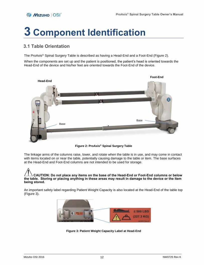
The ProAxis® Spinal Surgery Table is described as having a Head-End and a Foot-End (Figure 2).
When the components are set up and the patient is positioned, the patient’s head is oriented towards the Head-End of the device and his/her feet are oriented towards the Foot-End of the device.
Figure 2: ProAxis® Spinal Surgery Table
The linkage arms of the columns raise, lower, and rotate when the table is in use, and may come in contact with items located on or near the table, potentially causing damage to the table or item. The base surfaces at the Head-End and Foot-End columns are not intended to be used for storage.
CAUTION: Do not place any items on the base of the Head-End or Foot-End columns or below the table. Storing or placing anything in these areas may result in damage to the device or the item being stored.
An important safety label regarding Patient Weight Capacity is also located at the Head-End of the table top (Figure 3).
Figure 3: Patient Weight Capacity Label at Head-End
Head-End
Foot-End
Base
Base
ProAxis® Spinal Surgery Table Owner’s Manual
13 Mizuho OSI 2016 NW0725 Rev K
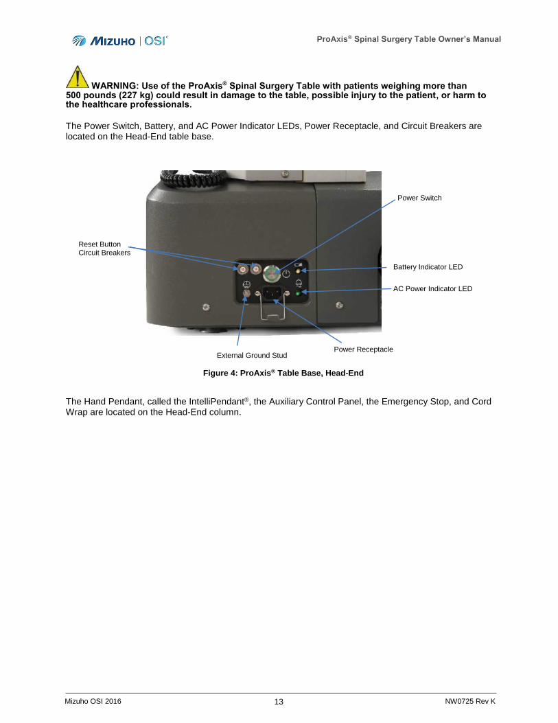
WARNING: Use of the ProAxis® Spinal Surgery Table with patients weighing more than 500 pounds (227 kg) could result in damage to the table, possible injury to the patient, or harm to the healthcare professionals.
The Power Switch, Battery, and AC Power Indicator LEDs, Power Receptacle, and Circuit Breakers are located on the Head-End table base.
Figure 4: ProAxis® Table Base, Head-End
The Hand Pendant, called the IntelliPendant®, the Auxiliary Control Panel, the Emergency Stop, and Cord Wrap are located on the Head-End column.
Power Switch
Reset Button Circuit Breakers
External Ground Stud Power Receptacle
AC Power Indicator LED
Battery Indicator LED
ProAxis® Spinal Surgery Table Owner’s Manual
14 Mizuho OSI 2016 NW0725 Rev K
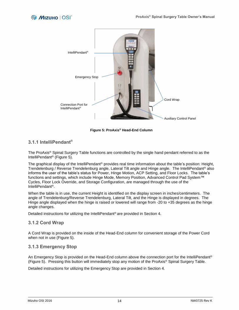
Figure 5: ProAxis® Head-End Column
3.1.1 IntelliPendant®
The ProAxis® Spinal Surgery Table functions are controlled by the single hand pendant referred to as the IntelliPendant® (Figure 5).
The graphical display of the IntelliPendant® provides real time information about the table’s position: Height, Trendelenburg / Reverse Trendelenburg angle, Lateral Tilt angle and Hinge angle. The IntelliPendant® also informs the user of the table’s status for Power, Hinge Motion, ACP Setting, and Floor Locks. The table’s functions and settings, which include Hinge Mode, Memory Position, Advanced Control Pad System™ Cycles, Floor Lock Override, and Storage Configuration, are managed through the use of the IntelliPendant®.
When the table is in use, the current Height is identified on the display screen in inches/centimeters. The angle of Trendelenburg/Reverse Trendelenburg, Lateral Tilt, and the Hinge is displayed in degrees. The Hinge angle displayed when the hinge is raised or lowered will range from -20 to +35 degrees as the hinge angle changes.
Detailed instructions for utilizing the IntelliPendant® are provided in Section 4.
3.1.2 Cord Wrap
A Cord Wrap is provided on the inside of the Head-End column for convenient storage of the Power Cord when not in use (Figure 5).
3.1.3 Emergency Stop
An Emergency Stop is provided on the Head-End column above the connection port for the IntelliPendant® (Figure 5). Pressing this button will immediately stop any motion of the ProAxis® Spinal Surgery Table.
Detailed instructions for utilizing the Emergency Stop are provided in Section 4.
IntelliPendant®
Emergency Stop
Auxiliary Control Panel
Connection Port for IntelliPendant®
Cord Wrap
ProAxis® Spinal Surgery Table Owner’s Manual
15 Mizuho OSI 2016 NW0725 Rev K
3.1.4 Auxiliary Control Panel
The Auxiliary Control Panel (Figure 5) is intended to provide a second option for controlling primary table motions and Floor Lock function. The Auxiliary Control Panel may be utilized to control table Height, Trendelenburg/Reverse Trendelenburg, Lateral Tilt, Hinge motion, and Floor Lock operation.
NOTE: Should the IntelliPendant® stop functioning, the Auxiliary Control Panel will allow the user to execute the basic motions of the table and lock/unlock the Floor Locks.
Detailed instructions for utilizing the Auxiliary Control Panel are provided in Section 4, Basic Operation.
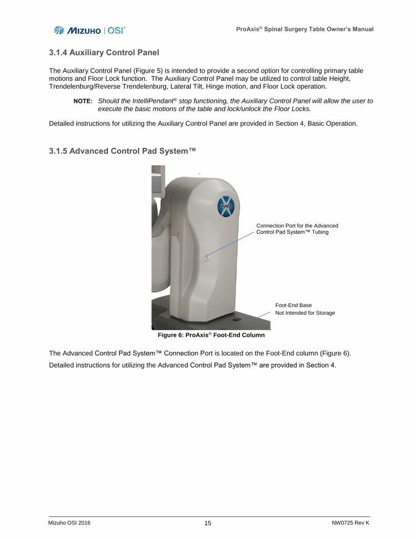
3.1.5 Advanced Control Pad System™
Figure 6: ProAxis® Foot-End Column
The Advanced Control Pad System™ Connection Port is located on the Foot-End column (Figure 6).
Detailed instructions for utilizing the Advanced Control Pad System™ are provided in Section 4.
Connection Port for the Advanced Control Pad System™ Tubing
Foot-End Base
Not Intended for Storage
ProAxis® Spinal Surgery Table Owner’s Manual
16 Mizuho OSI 2016 NW0725 Rev K
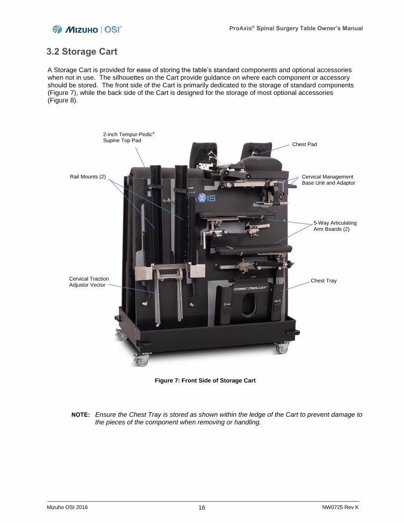
3.2 Storage Cart
A Storage Cart is provided for ease of storing the table’s standard components and optional accessories when not in use. The silhouettes on the Cart provide guidance on where each component or accessory should be stored. The front side of the Cart is primarily dedicated to the storage of standard components (Figure 7), while the back side of the Cart is designed for the storage of most optional accessories (Figure 8).
Figure 7: Front Side of Storage Cart
NOTE: Ensure the Chest Tray is stored as shown within the ledge of the Cart to prevent damage to the pieces of the component when removing or handling.
Chest Pad
Cervical Management Base Unit and Adaptor
5-Way Articulating Arm Boards (2)
Chest Tray Cervical Traction Adjustor Vector
Rail Mounts (2)
2-inch Tempur-Pedic® Supine Top Pad
ProAxis® Spinal Surgery Table Owner’s Manual
17 Mizuho OSI 2016 NW0725 Rev K
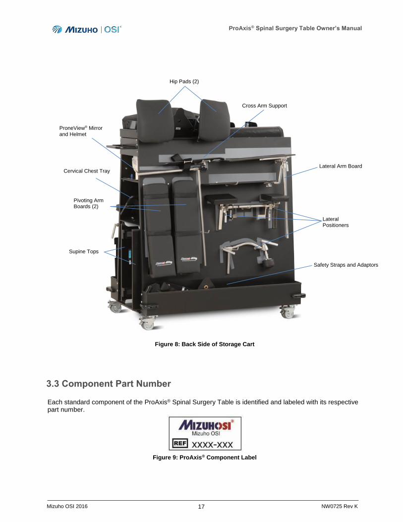
Figure 8: Back Side of Storage Cart
3.3 Component Part Number
Each standard component of the ProAxis® Spinal Surgery Table is identified and labeled with its respective part number.
Figure 9: ProAxis® Component Label
ProneView® Mirror and Helmet
Lateral Positioners
Lateral Arm Board
Pivoting Arm Boards (2)
Supine Tops
Cervical Chest Tray
Hip Pads (2)
Cross Arm Support
Safety Straps and Adaptors
ProAxis® Spinal Surgery Table Owner’s Manual
18 Mizuho OSI 2016 NW0725 Rev K
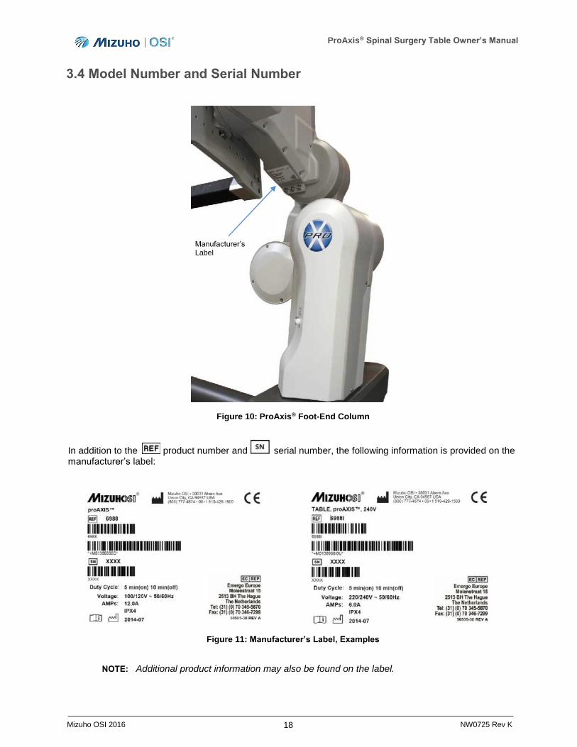
3.4 Model Number and Serial Number
Figure 10: ProAxis® Foot-End Column
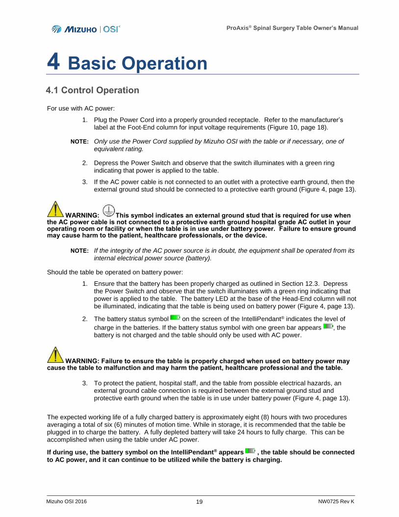
In addition to the product number and serial number, the following information is provided on the manufacturer’s label:
Figure 11: Manufacturer’s Label, Examples
NOTE: Additional product information may also be found on the label.
Manufacturer’s Label
ProAxis® Spinal Surgery Table Owner’s Manual
19 Mizuho OSI 2016 NW0725 Rev K
4 Basic Operation
4.1 Control Operation
For use with AC power:
1. Plug the Power Cord into a properly grounded receptacle. Refer to the manufacturer’s label at the Foot-End column for input voltage requirements (Figure 10, page 18).
NOTE: Only use the Power Cord supplied by Mizuho OSI with the table or if necessary, one of equivalent rating.
2. Depress the Power Switch and observe that the switch illuminates with a green ring indicating that power is applied to the table.
3. If the AC power cable is not connected to an outlet with a protective earth ground, then the external ground stud should be connected to a protective earth ground (Figure 4, page 13).
WARNING: This symbol indicates an external ground stud that is required for use when the AC power cable is not connected to a protective earth ground hospital grade AC outlet in your operating room or facility or when the table is in use under battery power. Failure to ensure ground may cause harm to the patient, healthcare professionals, or the device.
NOTE: If the integrity of the AC power source is in doubt, the equipment shall be operated from its internal electrical power source (battery).
Should the table be operated on battery power:
1. Ensure that the battery has been properly charged as outlined in Section 12.3. Depress the Power Switch and observe that the switch illuminates with a green ring indicating that power is applied to the table. The battery LED at the base of the Head-End column will not be illuminated, indicating that the table is being used on battery power (Figure 4, page 13).
2. The battery status symbol on the screen of the IntelliPendant® indicates the level of
charge in the batteries. If the battery status symbol with one green bar appears , the battery is not charged and the table should only be used with AC power.
WARNING: Failure to ensure the table is properly charged when used on battery power may cause the table to malfunction and may harm the patient, healthcare professional and the table.
3. To protect the patient, hospital staff, and the table from possible electrical hazards, an external ground cable connection is required between the external ground stud and protective earth ground when the table is in use under battery power (Figure 4, page 13).
The expected working life of a fully charged battery is approximately eight (8) hours with two procedures averaging a total of six (6) minutes of motion time. While in storage, it is recommended that the table be plugged in to charge the battery. A fully depleted battery will take 24 hours to fully charge. This can be accomplished when using the table under AC power.
If during use, the battery symbol on the IntelliPendant® appears , the table should be connected to AC power, and it can continue to be utilized while the battery is charging.
ProAxis® Spinal Surgery Table Owner’s Manual
20 Mizuho OSI 2016 NW0725 Rev K
4.2 Emergency Stop
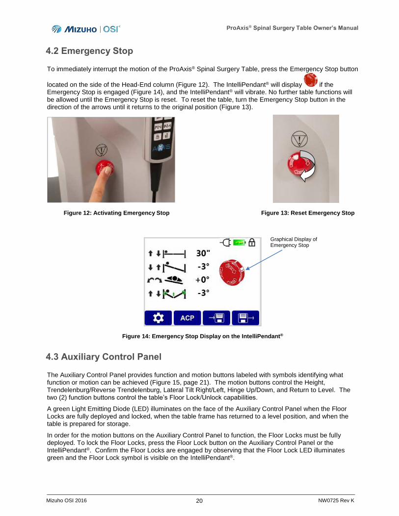
To immediately interrupt the motion of the ProAxis® Spinal Surgery Table, press the Emergency Stop button
located on the side of the Head-End column (Figure 12). The IntelliPendant® will display if the Emergency Stop is engaged (Figure 14), and the IntelliPendant® will vibrate. No further table functions will be allowed until the Emergency Stop is reset. To reset the table, turn the Emergency Stop button in the direction of the arrows until it returns to the original position (Figure 13).
Figure 12: Activating Emergency Stop Figure 13: Reset Emergency Stop
Figure 14: Emergency Stop Display on the IntelliPendant®
4.3 Auxiliary Control Panel
The Auxiliary Control Panel provides function and motion buttons labeled with symbols identifying what function or motion can be achieved (Figure 15, page 21). The motion buttons control the Height, Trendelenburg/Reverse Trendelenburg, Lateral Tilt Right/Left, Hinge Up/Down, and Return to Level. The two (2) function buttons control the table’s Floor Lock/Unlock capabilities.
A green Light Emitting Diode (LED) illuminates on the face of the Auxiliary Control Panel when the Floor Locks are fully deployed and locked, when the table frame has returned to a level position, and when the table is prepared for storage.
In order for the motion buttons on the Auxiliary Control Panel to function, the Floor Locks must be fully deployed. To lock the Floor Locks, press the Floor Lock button on the Auxiliary Control Panel or the IntelliPendant®. Confirm the Floor Locks are engaged by observing that the Floor Lock LED illuminates green and the Floor Lock symbol is visible on the IntelliPendant®.
Graphical Display of Emergency Stop
ProAxis® Spinal Surgery Table Owner’s Manual
21 Mizuho OSI 2016 NW0725 Rev K
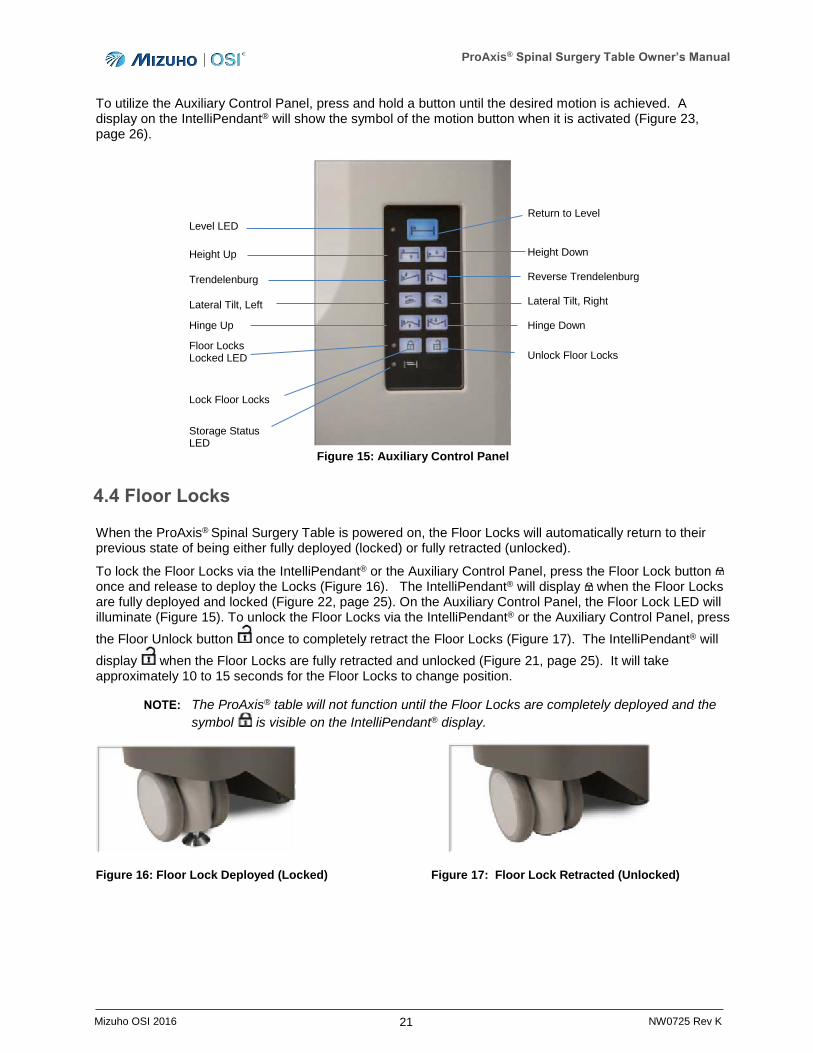
To utilize the Auxiliary Control Panel, press and hold a button until the desired motion is achieved. A display on the IntelliPendant® will show the symbol of the motion button when it is activated (Figure 23, page 26).
Figure 15: Auxiliary Control Panel
4.4 Floor Locks
When the ProAxis® Spinal Surgery Table is powered on, the Floor Locks will automatically return to their previous state of being either fully deployed (locked) or fully retracted (unlocked).
To lock the Floor Locks via the IntelliPendant® or the Auxiliary Control Panel, press the Floor Lock button once and release to deploy the Locks (Figure 16). The IntelliPendant® will display when the Floor Locks are fully deployed and locked (Figure 22, page 25). On the Auxiliary Control Panel, the Floor Lock LED will illuminate (Figure 15). To unlock the Floor Locks via the IntelliPendant® or the Auxiliary Control Panel, press
the Floor Unlock button once to completely retract the Floor Locks (Figure 17). The IntelliPendant® will
display when the Floor Locks are fully retracted and unlocked (Figure 21, page 25). It will take approximately 10 to 15 seconds for the Floor Locks to change position.
NOTE: The ProAxis® table will not function until the Floor Locks are completely deployed and the
symbol is visible on the IntelliPendant® display.
Figure 16: Floor Lock Deployed (Locked) Figure 17: Floor Lock Retracted (Unlocked)
Return to Level
Height Down Reverse Trendelenburg Lateral Tilt, Right Hinge Down
Unlock Floor Locks
Level LED
Height Up
Trendelenburg
Lateral Tilt, Left
Hinge Up
Floor Locks Locked LED
Lock Floor Locks
Storage Status LED

ProAxis® Spinal Surgery Table Owner’s Manual
22 Mizuho OSI 2016 NW0725 Rev K
4.4.1 IntelliPendant® Activated Floor Lock Override
If the Floor Lock systems fail during table use such that powered table motion is prevented, the IntelliPendant® can be used to activate the Floor Lock Override function (see Section 4.7.4.4, page 35). Use of the Floor Lock Override function will allow for 60 seconds of activity during which multiple actions can be taken.
NOTE: Should a particular motion take longer than 60 seconds, the action will be completed as long as the function button continues to be depressed.
NOTE: The Floor Lock Override function allows for changes to Height, Trendelenburg/Reverse Trendelenburg, Lateral Roll, Hinge, and Return to Level functions via the Hand Pendant and is intended for use in emergency situations only.
4.4.2 Manual Floor Lock Override
In the event the table’s floor locks do not retract properly to allow for table transport, the Floor Locks can be manually raised or lowered (see Section 0).
NOTE: The manual floor lock override is intended only as a means of transporting the table should the Floor Lock systems fail. Use of this override will not allow the user to activate any of the table functions.
4.5 Moving the Table
Before moving the ProAxis® Spinal Surgery Table or preparing it for its storage sequence of movements, ensure the table is returned to its Home position such that it is neutral and at a maximum height of 32 inches (81 cm).
CAUTION: When moving the ProAxis® Spinal Surgery Table in its normal configuration, ensure that the table is at a height no greater than its home position of 32 inches (81 cm) and in a
neutral state with the IntelliPendant® reading 0º for Lateral Roll, Trendelenburg/Reverse Trendelenburg and Hinge to prevent the table from being unstable during relocation.
After all four (4) Floor Locks are unlocked, the table can be rolled for relocation. The ProAxis® Spinal Surgery Table is heavy, and a minimum of two people is required to move it. Position one person at the Head-End of the table and one person at the Foot-End. Care should be taken to control the ProAxis® when rolling it.
CAUTION: If the ProAxis® Spinal Surgery Table is allowed to roll too fast, it may be difficult to stop or turn. Impact of the table with a stationary object may cause serious damage to the table or the other object. If an impact does occur the table must be visually inspected for damage, and a Function Check must be performed (refer to Section 6). If damage is discovered or the table does not successfully complete the Function Check, call Mizuho OSI Services (refer to Section 13).
NOTE: For easier moving and storage, the ProAxis® Spinal Surgery Table may also be configured to its retracted position of 80 inches (203 cm) (see Section 4.7.5).
ProAxis® Spinal Surgery Table Owner’s Manual
23 Mizuho OSI 2016 NW0725 Rev K
4.6 Torso Trolley®
The Torso Trolley® is designed to support the patient and simultaneously move the prone patient’s upper torso in conjunction with the hinge angle being changed, preventing any spinal compression or distraction.
The Torso Trolley® is formed by utilizing the Chest Tray to which the chest pad is mounted. The 5-Way Adjustable Arm Boards are also mounted to the Chest Tray utilizing the Arm Board Brackets provided. Refer to Section 8 for detailed instructions on the setup and use of the Torso Trolley®.
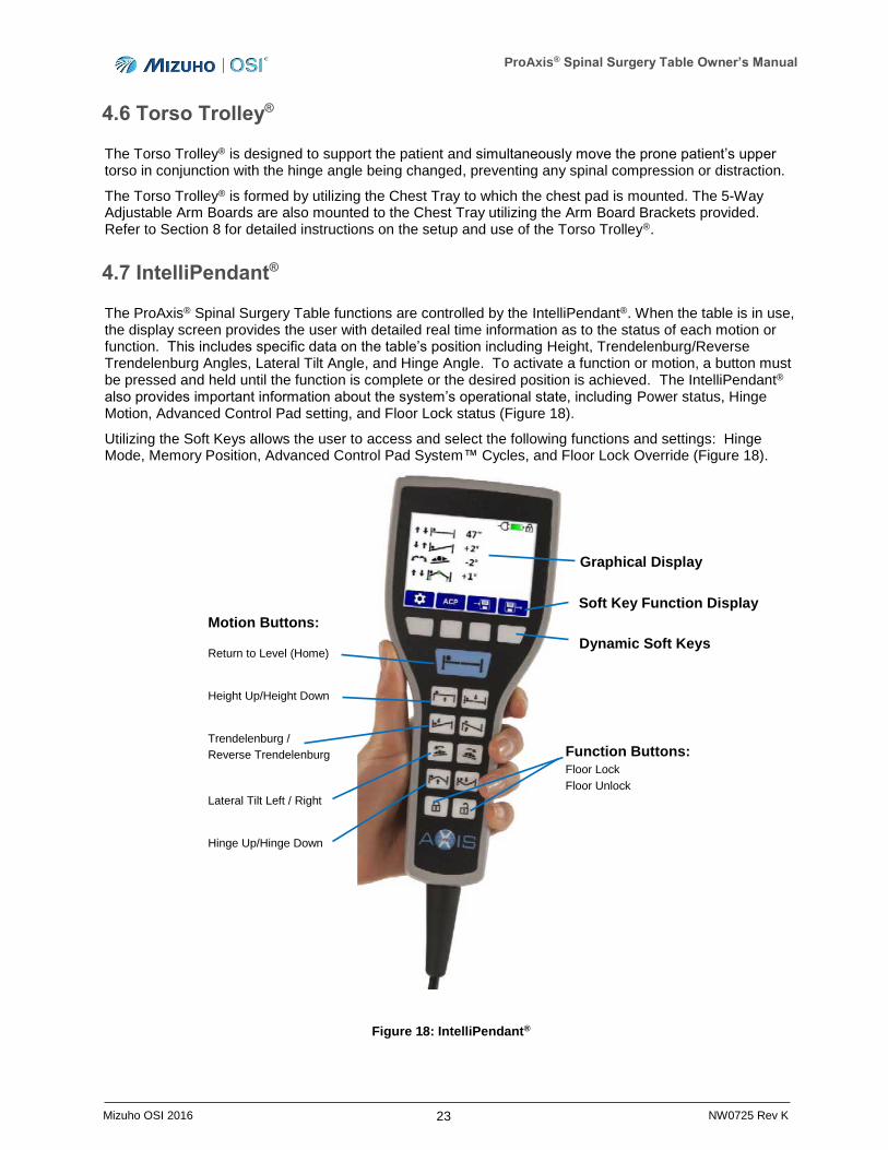
4.7 IntelliPendant®
The ProAxis® Spinal Surgery Table functions are controlled by the IntelliPendant®. When the table is in use, the display screen provides the user with detailed real time information as to the status of each motion or function. This includes specific data on the table’s position including Height, Trendelenburg/Reverse Trendelenburg Angles, Lateral Tilt Angle, and Hinge Angle. To activate a function or motion, a button must be pressed and held until the function is complete or the desired position is achieved. The IntelliPendant®
also provides important information about the system’s operational state, including Power status, Hinge Motion, Advanced Control Pad setting, and Floor Lock status (Figure 18).
Utilizing the Soft Keys allows the user to access and select the following functions and settings: Hinge Mode, Memory Position, Advanced Control Pad System™ Cycles, and Floor Lock Override (Figure 18).
Figure 18: IntelliPendant®
Motion Buttons:
Return to Level (Home)
Height Up/Height Down
Trendelenburg /
Reverse Trendelenburg
Lateral Tilt Left / Right
Hinge Up/Hinge Down
Graphical Display
Dynamic Soft Keys
Function Buttons:
Floor Lock
Floor Unlock
Soft Key Function Display
ProAxis® Spinal Surgery Table Owner’s Manual
24 Mizuho OSI 2016 NW0725 Rev K
The IntelliPendant® also provides haptic feedback to the user when a requested action is not possible. This may occur under the following conditions:
Floor Locks are Unlocked and must be engaged before continuing.
The maximum range of a particular motion has been reached.
A system error has occurred.
A visual indication of the constrained movement will also be displayed on the IntelliPendant® screen informing the user of the table’s state. For instances where a particular table function has reached its limit, the image depicted on the screen will show the location of the error or limit through the use of an orange circle (see Section 4.7.2).
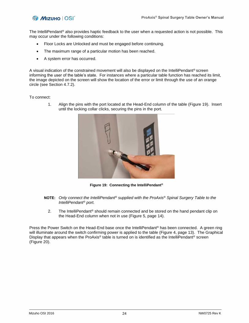
To connect:
1. Align the pins with the port located at the Head-End column of the table (Figure 19). Insert until the locking collar clicks, securing the pins in the port.
Figure 19: Connecting the IntelliPendant®
NOTE: Only connect the IntelliPendant® supplied with the ProAxis® Spinal Surgery Table to the IntelliPendant® port.
2. The IntelliPendant® should remain connected and be stored on the hand pendant clip on the Head-End column when not in use (Figure 5, page 14).
Press the Power Switch on the Head-End base once the IntelliPendant® has been connected. A green ring will illuminate around the switch confirming power is applied to the table (Figure 4, page 13). The Graphical Display that appears when the ProAxis® table is turned on is identified as the IntelliPendant® screen (Figure 20).
ProAxis® Spinal Surgery Table Owner’s Manual
25 Mizuho OSI 2016 NW0725 Rev K
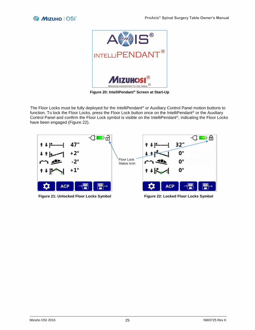
Figure 20: IntelliPendant® Screen at Start-Up
The Floor Locks must be fully deployed for the IntelliPendant® or Auxiliary Control Panel motion buttons to function. To lock the Floor Locks, press the Floor Lock button once on the IntelliPendant® or the Auxiliary Control Panel and confirm the Floor Lock symbol is visible on the IntelliPendant®, indicating the Floor Locks have been engaged (Figure 22).
Figure 21: Unlocked Floor Locks Symbol Figure 22: Locked Floor Locks Symbol
Floor Lock Status Icon
ProAxis® Spinal Surgery Table Owner’s Manual
26 Mizuho OSI 2016 NW0725 Rev K
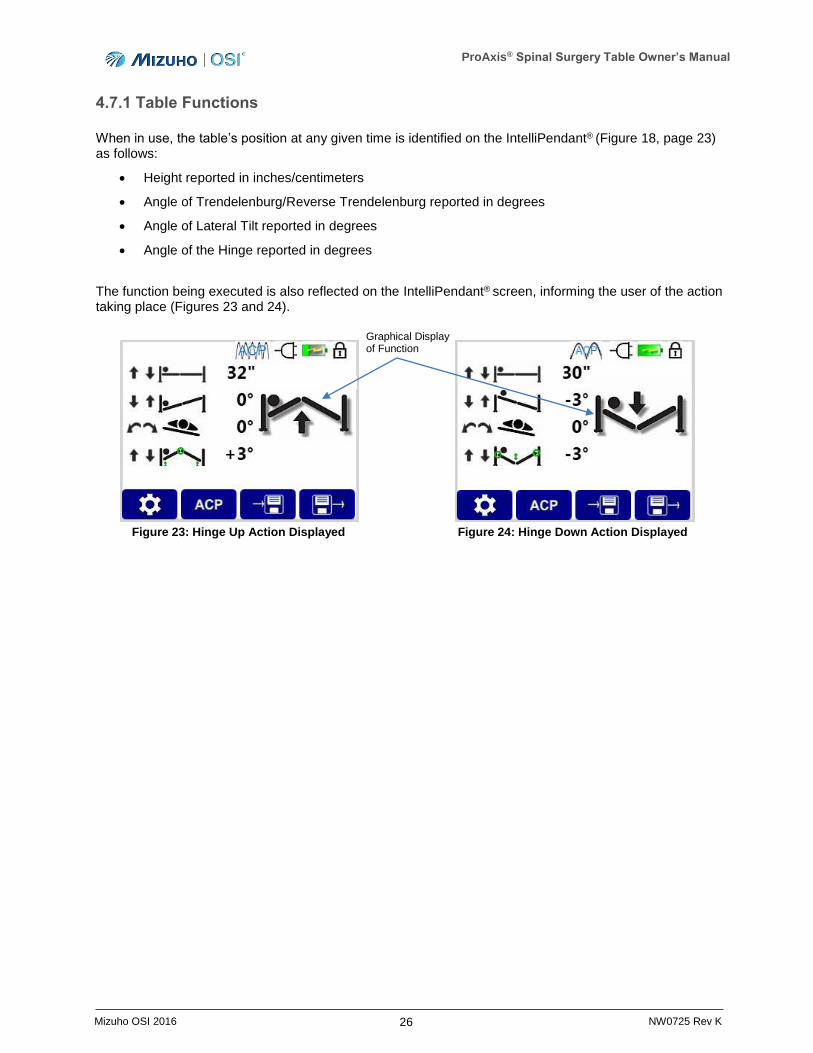
4.7.1 Table Functions
When in use, the table’s position at any given time is identified on the IntelliPendant® (Figure 18, page 23) as follows:
Height reported in inches/centimeters
Angle of Trendelenburg/Reverse Trendelenburg reported in degrees
Angle of Lateral Tilt reported in degrees
Angle of the Hinge reported in degrees
The function being executed is also reflected on the IntelliPendant® screen, informing the user of the action taking place (Figures 23 and 24).
Figure 23: Hinge Up Action Displayed Figure 24: Hinge Down Action Displayed
Graphical Display of Function
ProAxis® Spinal Surgery Table Owner’s Manual
27 Mizuho OSI 2016 NW0725 Rev K
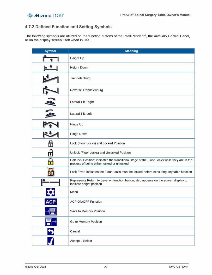
4.7.2 Defined Function and Setting Symbols
The following symbols are utilized on the function buttons of the IntelliPendant®, the Auxiliary Control Panel, or on the display screen itself when in use.
Symbol Meaning
Height Up
Height Down
Trendelenburg
Reverse Trendelenburg
Lateral Tilt, Right
Lateral Tilt, Left
Hinge Up
Hinge Down
Lock (Floor Locks) and Locked Position
Unlock (Floor Locks) and Unlocked Position
Half-lock Position; indicates the transitional stage of the Floor Locks while they are in the process of being either locked or unlocked
Lock Error; indicates the Floor Locks must be locked before executing any table function
Represents Return to Level on function button, also appears on the screen display to indicate height position
Menu
ACP ON/OFF Function
Save to Memory Position
Go to Memory Position
Cancel
Accept / Select
ProAxis® Spinal Surgery Table Owner’s Manual
28 Mizuho OSI 2016 NW0725 Rev K
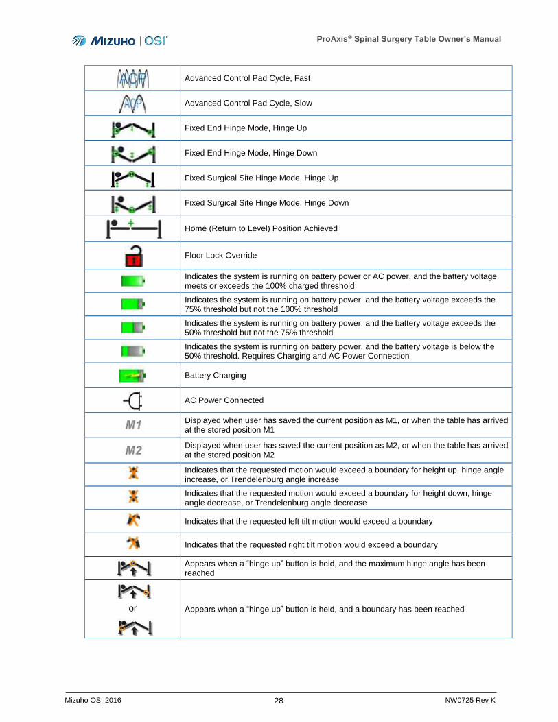
Advanced Control Pad Cycle, Fast
Advanced Control Pad Cycle, Slow
Fixed End Hinge Mode, Hinge Up
Fixed End Hinge Mode, Hinge Down
Fixed Surgical Site Hinge Mode, Hinge Up
Fixed Surgical Site Hinge Mode, Hinge Down
Home (Return to Level) Position Achieved
Floor Lock Override
Indicates the system is running on battery power or AC power, and the battery voltage meets or exceeds the 100% charged threshold
Indicates the system is running on battery power, and the battery voltage exceeds the 75% threshold but not the 100% threshold
Indicates the system is running on battery power, and the battery voltage exceeds the 50% threshold but not the 75% threshold
Indicates the system is running on battery power, and the battery voltage is below the 50% threshold. Requires Charging and AC Power Connection
Battery Charging
AC Power Connected
Displayed when user has saved the current position as M1, or when the table has arrived at the stored position M1
Displayed when user has saved the current position as M2, or when the table has arrived at the stored position M2
Indicates that the requested motion would exceed a boundary for height up, hinge angle increase, or Trendelenburg angle increase
Indicates that the requested motion would exceed a boundary for height down, hinge angle decrease, or Trendelenburg angle decrease
Indicates that the requested left tilt motion would exceed a boundary
Indicates that the requested right tilt motion would exceed a boundary
Appears when a “hinge up” button is held, and the maximum hinge angle has been reached
or
Appears when a “hinge up” button is held, and a boundary has been reached
ProAxis® Spinal Surgery Table Owner’s Manual
29 Mizuho OSI 2016 NW0725 Rev K
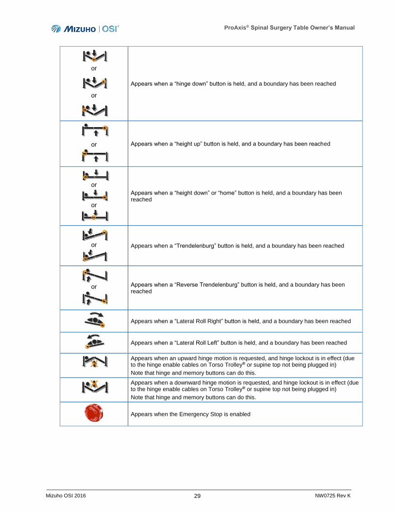
or
or
Appears when a “hinge down” button is held, and a boundary has been reached
or
Appears when a “height up” button is held, and a boundary has been reached
or
or
Appears when a “height down” or “home” button is held, and a boundary has been reached
or
Appears when a “Trendelenburg” button is held, and a boundary has been reached
or
Appears when a “Reverse Trendelenburg” button is held, and a boundary has been reached
Appears when a “Lateral Roll Right” button is held, and a boundary has been reached
Appears when a “Lateral Roll Left” button is held, and a boundary has been reached
Appears when an upward hinge motion is requested, and hinge lockout is in effect (due to the hinge enable cables on Torso Trolley® or supine top not being plugged in)
Note that hinge and memory buttons can do this.
Appears when a downward hinge motion is requested, and hinge lockout is in effect (due to the hinge enable cables on Torso Trolley® or supine top not being plugged in)
Note that hinge and memory buttons can do this.
Appears when the Emergency Stop is enabled
ProAxis® Spinal Surgery Table Owner’s Manual
30 Mizuho OSI 2016 NW0725 Rev K
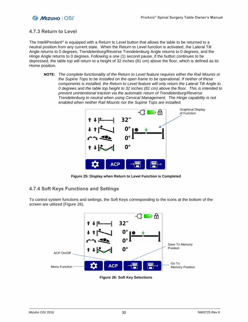
4.7.3 Return to Level
The IntelliPendant® is equipped with a Return to Level button that allows the table to be returned to a neutral position from any current state. When the Return to Level function is activated, the Lateral Tilt Angle returns to 0 degrees, Trendelenburg/Reverse Trendelenburg Angle returns to 0 degrees, and the Hinge Angle returns to 0 degrees. Following a one (1) second pause, if the button continues to be depressed, the table top will return to a height of 32 inches (81 cm) above the floor, which is defined as its Home position.
NOTE: The complete functionality of the Return to Level feature requires either the Rail Mounts or the Supine Tops to be installed on the open frame to be operational. If neither of these components is installed, the Return to Level feature will only return the Lateral Tilt Angle to 0 degrees and the table top height to 32 inches (81 cm) above the floor. This is intended to prevent unintentional traction via the automatic return of Trendelenburg/Reverse Trendelenburg to neutral when using Cervical Management. The Hinge capability is not enabled when neither Rail Mounts nor the Supine Tops are installed.
Figure 25: Display when Return to Level Function is Completed
4.7.4 Soft Keys Functions and Settings
To control system functions and settings, the Soft Keys corresponding to the icons at the bottom of the screen are utilized (Figure 26).
Figure 26: Soft Key Selections
Menu Function
ACP On/Off
Save To Memory Position
Go To Memory Position
Graphical Display of Function

ProAxis® Spinal Surgery Table Owner’s Manual
31 Mizuho OSI 2016 NW0725 Rev K
Pressing the Menu Key provides the user with a list of setting choices for the table, which may be selected and customized as needed for each procedure (Figure 27).
Figure 27: Menu Key Selections
4.7.4.1 Memory Positioning
The ProAxis® Spinal Surgery Table has the ability to store two specified table positions in memory for ease of returning to the desired position at a later time. The table positions can be stored to either Memory Position 1 or Memory Position 2.
Assignment of the table position to memory is completed through the use of the IntelliPendant®.
To assign the table’s current position to a memory position:
1. From the Home Screen, select the Save to Memory Position using the corresponding Soft Key (Figure 26).
2. Assign the table position to either the Memory Position 1 or Memory Position 2 location (Figure 28).
Figure 28: Memory Position Selection
3. The table position is now saved.

ProAxis® Spinal Surgery Table Owner’s Manual
32 Mizuho OSI 2016 NW0725 Rev K
To move the table from its current position to a saved memory position:
1. From the Home Screen, select the Go To Memory Position using the corresponding Soft Key (Figure 26).
2. Press and hold the Soft Key corresponding to either Memory Position 1 or Memory Position 2 to move to the desired location.
NOTE: If the hinge capability is not enabled (see Section 8 for setup instructions) and the desired Memory Position requires a change in hinge angle, the selection of Memory Positions will not provide the desired motion to the stored position requested.
4.7.4.2 Hinge Mode
The ProAxis® Spinal Surgery Table has two operating modes for the hinged frame, Fixed Surgical Site (FSS) or Fixed End (FE), which can be selected depending on the surgeon’s preference for positioning the patient.
FSS mode is designed to ensure the height of the top at the hinge remains constant when the hinge is flexed or extended. This is accomplished through the simultaneous motions of the Head-End and Foot-End of the table. This mode is utilized primarily for prone patient positioning.
FE mode is designed to ensure the height of the Head-End and Foot-End of the table top remains at a constant height when the hinge is flexed or extended. This mode is utilized primarily for lateral patient positioning.
NOTE: For the hinge of the frame to be operational, the Rail Mounts or the Supine Top, Head-End needs to be installed and the cables connected. Refer to Section 8 for setup instructions.
Selection of the hinge mode is completed through the use of the IntelliPendant®.
To activate the desired Hinge Mode:
1. Press the Menu Soft Key on the IntelliPendant® and observe that the Set Hinge Mode setting is selected (Figure 27).
2. Upon confirming that Set Hinge Mode is highlighted, press the Soft Key that corresponds to the check mark.
3. Utilize the arrow Soft Keys to highlight the FSS or FE mode, and press the check mark Soft Key to select the desired hinge mode (Figure 29).
Figure 29: Hinge Mode Selection
Up / Down Arrows Check Mark
Hinge Mode Options
ProAxis® Spinal Surgery Table Owner’s Manual
33 Mizuho OSI 2016 NW0725 Rev K
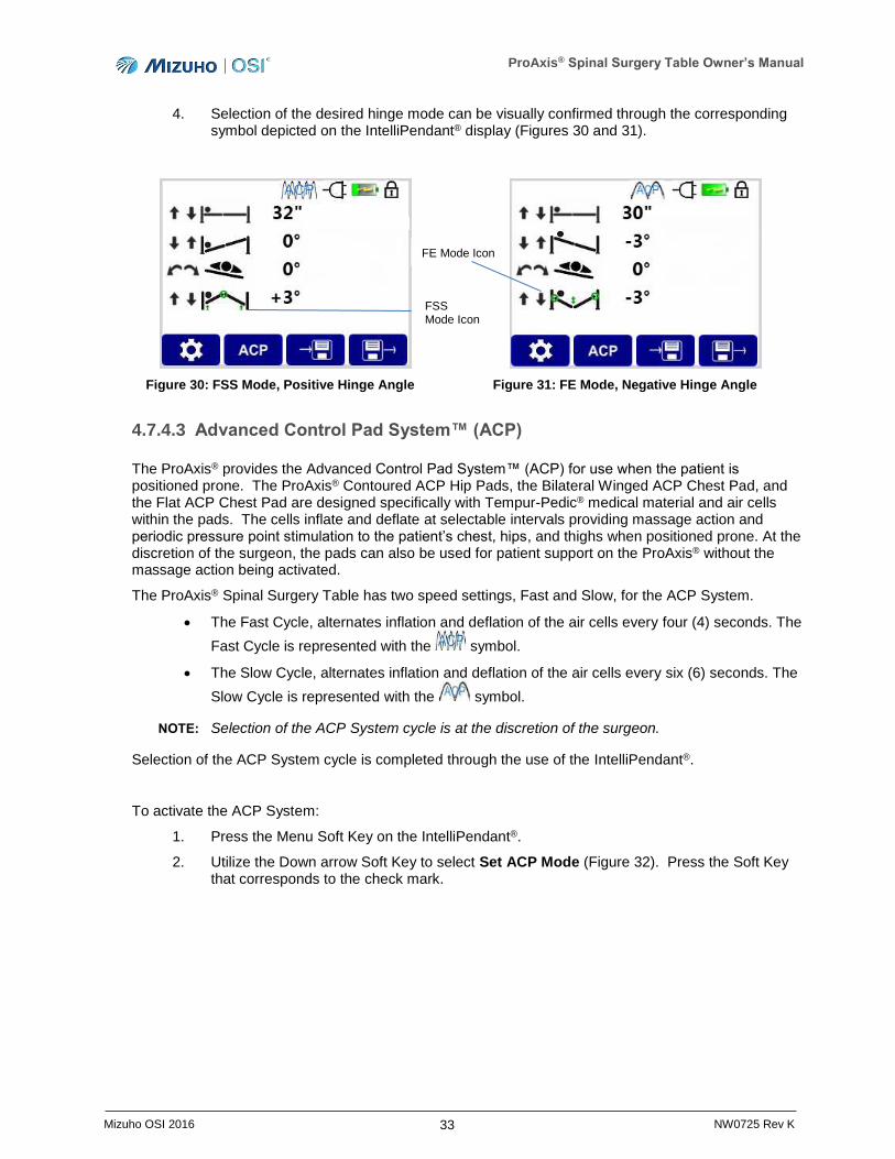
4. Selection of the desired hinge mode can be visually confirmed through the corresponding symbol depicted on the IntelliPendant® display (Figures 30 and 31).
Figure 30: FSS Mode, Positive Hinge Angle Figure 31: FE Mode, Negative Hinge Angle
4.7.4.3 Advanced Control Pad System™ (ACP)
The ProAxis® provides the Advanced Control Pad System™ (ACP) for use when the patient is positioned prone. The ProAxis® Contoured ACP Hip Pads, the Bilateral Winged ACP Chest Pad, and the Flat ACP Chest Pad are designed specifically with Tempur-Pedic® medical material and air cells within the pads. The cells inflate and deflate at selectable intervals providing massage action and periodic pressure point stimulation to the patient’s chest, hips, and thighs when positioned prone. At the discretion of the surgeon, the pads can also be used for patient support on the ProAxis® without the massage action being activated.
The ProAxis® Spinal Surgery Table has two speed settings, Fast and Slow, for the ACP System.
The Fast Cycle, alternates inflation and deflation of the air cells every four (4) seconds. The
Fast Cycle is represented with the symbol.
The Slow Cycle, alternates inflation and deflation of the air cells every six (6) seconds. The
Slow Cycle is represented with the symbol.
NOTE: Selection of the ACP System cycle is at the discretion of the surgeon.
Selection of the ACP System cycle is completed through the use of the IntelliPendant®.
To activate the ACP System:
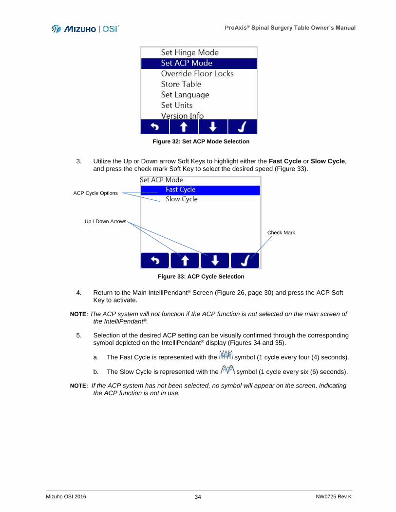
1. Press the Menu Soft Key on the IntelliPendant®.
2. Utilize the Down arrow Soft Key to select Set ACP Mode (Figure 32). Press the Soft Key that corresponds to the check mark.
FE Mode Icon
FSS Mode Icon
ProAxis® Spinal Surgery Table Owner’s Manual
34 Mizuho OSI 2016 NW0725 Rev K
Figure 32: Set ACP Mode Selection
3. Utilize the Up or Down arrow Soft Keys to highlight either the Fast Cycle or Slow Cycle, and press the check mark Soft Key to select the desired speed (Figure 33).
Figure 33: ACP Cycle Selection
4. Return to the Main IntelliPendant® Screen (Figure 26, page 30) and press the ACP Soft Key to activate.
NOTE: The ACP system will not function if the ACP function is not selected on the main screen of the IntelliPendant®.
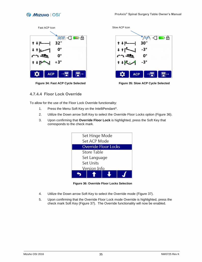
5. Selection of the desired ACP setting can be visually confirmed through the corresponding symbol depicted on the IntelliPendant® display (Figures 34 and 35).
a. The Fast Cycle is represented with the symbol (1 cycle every four (4) seconds).
b. The Slow Cycle is represented with the symbol (1 cycle every six (6) seconds).
NOTE: If the ACP system has not been selected, no symbol will appear on the screen, indicating the ACP function is not in use.
Up / Down Arrows
ACP Cycle Options
Check Mark
ProAxis® Spinal Surgery Table Owner’s Manual
35 Mizuho OSI 2016 NW0725 Rev K
Figure 34: Fast ACP Cycle Selected Figure 35: Slow ACP Cycle Selected
4.7.4.4 Floor Lock Override
To allow for the use of the Floor Lock Override functionality:
1. Press the Menu Soft Key on the IntelliPendant®.
2. Utilize the Down arrow Soft Key to select the Override Floor Locks option (Figure 36).
3. Upon confirming that Override Floor Lock is highlighted, press the Soft Key that corresponds to the check mark.
Figure 36: Override Floor Locks Selection
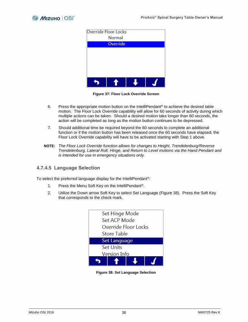
4. Utilize the Down arrow Soft Key to select the Override mode (Figure 37).
5. Upon confirming that the Override Floor Lock mode Override is highlighted, press the check mark Soft Key (Figure 37). The Override functionality will now be enabled.
Slow ACP Icon Fast ACP Icon
ProAxis® Spinal Surgery Table Owner’s Manual
36 Mizuho OSI 2016 NW0725 Rev K
Figure 37: Floor Lock Override Screen
6. Press the appropriate motion button on the IntelliPendant® to achieve the desired table motion. The Floor Lock Override capability will allow for 60 seconds of activity during which multiple actions can be taken. Should a desired motion take longer than 60 seconds, the action will be completed as long as the motion button continues to be depressed.
7. Should additional time be required beyond the 60 seconds to complete an additional function or if the motion button has been released once the 60 seconds have elapsed, the Floor Lock Override capability will have to be activated starting with Step 1 above.
NOTE: The Floor Lock Override function allows for changes to Height, Trendelenburg/Reverse Trendelenburg, Lateral Roll, Hinge, and Return to Level motions via the Hand Pendant and is intended for use in emergency situations only.
4.7.4.5 Language Selection
To select the preferred language display for the IntelliPendant®:
1. Press the Menu Soft Key on the IntelliPendant®.
2. Utilize the Down arrow Soft Key to select Set Language (Figure 38). Press the Soft Key that corresponds to the check mark.
Figure 38: Set Language Selection
ProAxis® Spinal Surgery Table Owner’s Manual
37 Mizuho OSI 2016 NW0725 Rev K
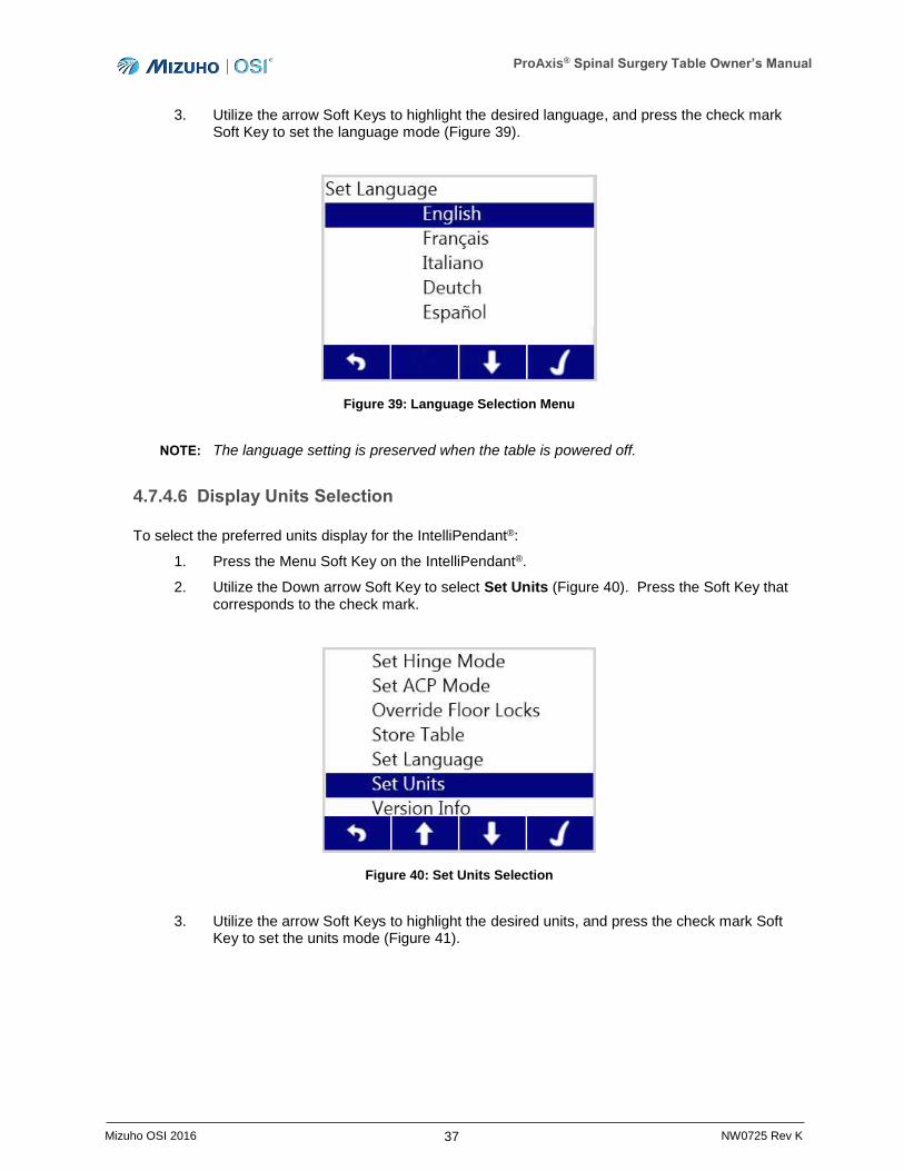
3. Utilize the arrow Soft Keys to highlight the desired language, and press the check mark Soft Key to set the language mode (Figure 39).
Figure 39: Language Selection Menu
NOTE: The language setting is preserved when the table is powered off.
4.7.4.6 Display Units Selection
To select the preferred units display for the IntelliPendant®:
1. Press the Menu Soft Key on the IntelliPendant®.
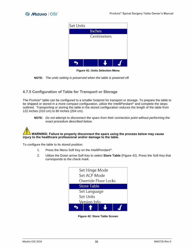
2. Utilize the Down arrow Soft Key to select Set Units (Figure 40). Press the Soft Key that corresponds to the check mark.
Figure 40: Set Units Selection
3. Utilize the arrow Soft Keys to highlight the desired units, and press the check mark Soft Key to set the units mode (Figure 41).
ProAxis® Spinal Surgery Table Owner’s Manual
38 Mizuho OSI 2016 NW0725 Rev K
Figure 41: Units Selection Menu
NOTE: The units setting is preserved when the table is powered off.
4.7.5 Configuration of Table for Transport or Storage
The ProAxis® table can be configured to a smaller footprint for transport or storage. To prepare the table to be shipped or stored in a more compact configuration, utilize the IntelliPendant® and complete the steps outlined. Transporting or storing the table in the stored configuration reduces the length of the table from 122 inches (310 cm) to 80 inches (204 cm).
NOTE: Do not attempt to disconnect the spars from their connection point without performing the exact procedure described below.
WARNING: Failure to properly disconnect the spars using the process below may cause injury to the healthcare professional and/or damage to the table.
To configure the table to its stored position:
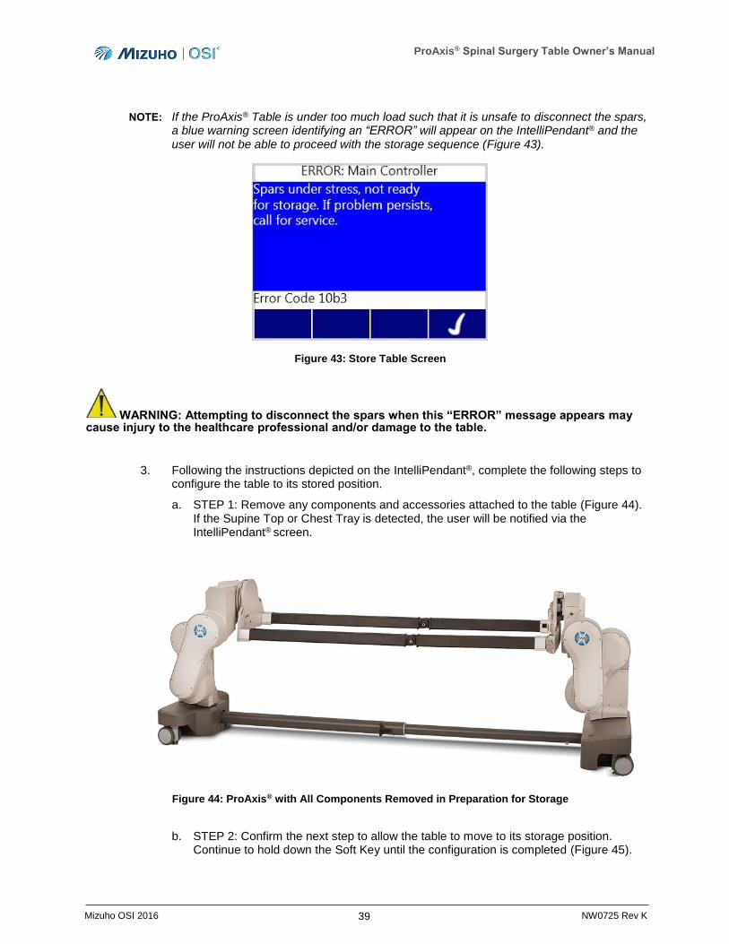
1. Press the Menu Soft Key on the IntelliPendant®.
2. Utilize the Down arrow Soft Key to select Store Table (Figure 42). Press the Soft Key that corresponds to the check mark.
Figure 42: Store Table Screen
ProAxis® Spinal Surgery Table Owner’s Manual
39 Mizuho OSI 2016 NW0725 Rev K
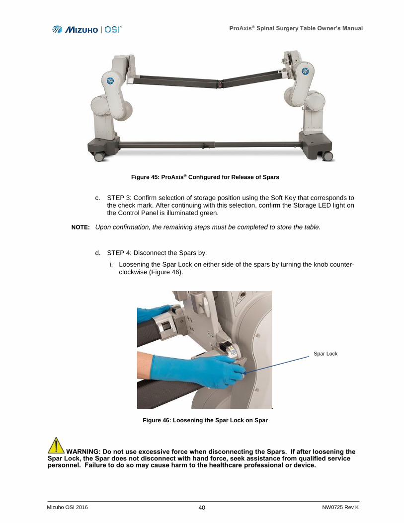
NOTE: If the ProAxis® Table is under too much load such that it is unsafe to disconnect the spars, a blue warning screen identifying an “ERROR” will appear on the IntelliPendant® and the user will not be able to proceed with the storage sequence (Figure 43).
Figure 43: Store Table Screen
WARNING: Attempting to disconnect the spars when this “ERROR” message appears may cause injury to the healthcare professional and/or damage to the table.
3. Following the instructions depicted on the IntelliPendant®, complete the following steps to configure the table to its stored position.
a. STEP 1: Remove any components and accessories attached to the table (Figure 44). If the Supine Top or Chest Tray is detected, the user will be notified via the IntelliPendant® screen.
Figure 44: ProAxis® with All Components Removed in Preparation for Storage
b. STEP 2: Confirm the next step to allow the table to move to its storage position. Continue to hold down the Soft Key until the configuration is completed (Figure 45).
ProAxis® Spinal Surgery Table Owner’s Manual
40 Mizuho OSI 2016 NW0725 Rev K
Figure 45: ProAxis® Configured for Release of Spars
c. STEP 3: Confirm selection of storage position using the Soft Key that corresponds to the check mark. After continuing with this selection, confirm the Storage LED light on the Control Panel is illuminated green.
NOTE: Upon confirmation, the remaining steps must be completed to store the table.
d. STEP 4: Disconnect the Spars by:
i. Loosening the Spar Lock on either side of the spars by turning the knob counter-clockwise (Figure 46).
.
Figure 46: Loosening the Spar Lock on Spar
WARNING: Do not use excessive force when disconnecting the Spars. If after loosening the Spar Lock, the Spar does not disconnect with hand force, seek assistance from qualified service personnel. Failure to do so may cause harm to the healthcare professional or device.
Spar Lock

ProAxis® Spinal Surgery Table Owner’s Manual
41 Mizuho OSI 2016 NW0725 Rev K
ii. Simultaneously pressing down on the black tabs on each side of the table to disconnect the spars from their locked position (Figure 47) and raise them out of the latches.
Figure 47: Pressing down on the black tab to disconnect the Spar
iii. Remove the spars by lifting up and shifting the pair of spars to either side such that they can drop down for storage (Figure 48).
Figure 48: Disconnecting the Spars
Black Tab
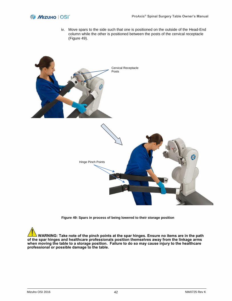
ProAxis® Spinal Surgery Table Owner’s Manual
42 Mizuho OSI 2016 NW0725 Rev K
iv. Move spars to the side such that one is positioned on the outside of the Head-End column while the other is positioned between the posts of the cervical receptacle (Figure 49).
Figure 49: Spars in process of being lowered to their storage position
WARNING: Take note of the pinch points at the spar hinges. Ensure no items are in the path of the spar hinges and healthcare professionals position themselves away from the linkage arms when moving the table to a storage position. Failure to do so may cause injury to the healthcare professional or possible damage to the table.
Cervical Receptacle Posts
Hinge Pinch Points
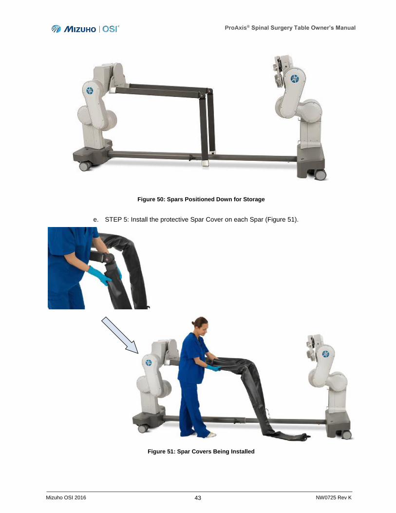
ProAxis® Spinal Surgery Table Owner’s Manual
43 Mizuho OSI 2016 NW0725 Rev K
Figure 50: Spars Positioned Down for Storage
e. STEP 5: Install the protective Spar Cover on each Spar (Figure 51).
Figure 51: Spar Covers Being Installed
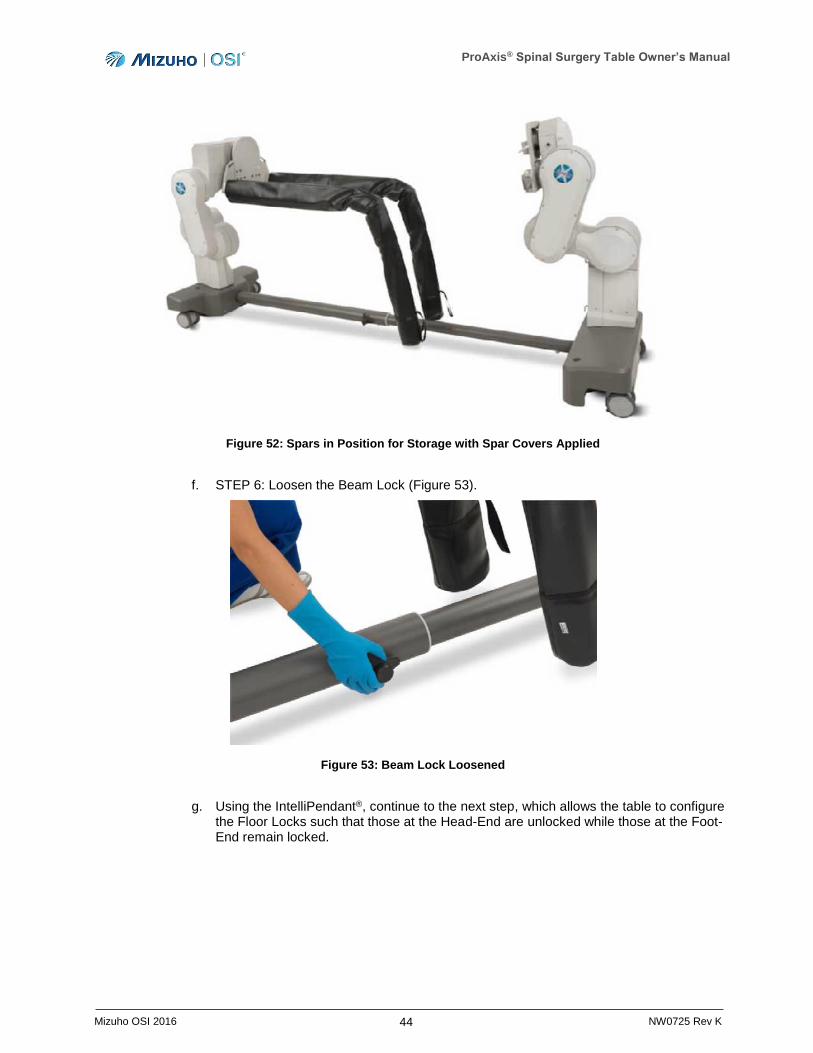
ProAxis® Spinal Surgery Table Owner’s Manual
44 Mizuho OSI 2016 NW0725 Rev K
Figure 52: Spars in Position for Storage with Spar Covers Applied
f. STEP 6: Loosen the Beam Lock (Figure 53).
Figure 53: Beam Lock Loosened
g. Using the IntelliPendant®, continue to the next step, which allows the table to configure the Floor Locks such that those at the Head-End are unlocked while those at the Foot-End remain locked.
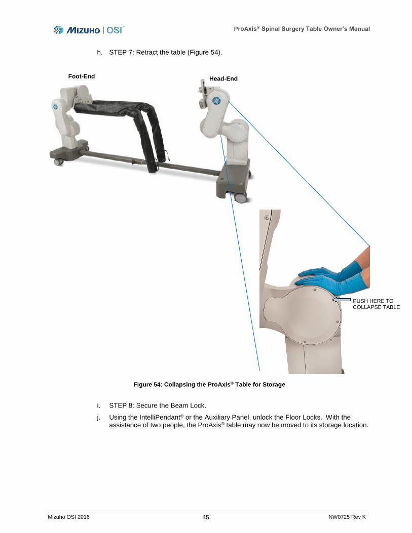
ProAxis® Spinal Surgery Table Owner’s Manual
45 Mizuho OSI 2016 NW0725 Rev K
h. STEP 7: Retract the table (Figure 54).
Figure 54: Collapsing the ProAxis® Table for Storage
i. STEP 8: Secure the Beam Lock.
j. Using the IntelliPendant® or the Auxiliary Panel, unlock the Floor Locks. With the assistance of two people, the ProAxis® table may now be moved to its storage location.
Head-End Foot-End
PUSH HERE TO COLLAPSE TABLE
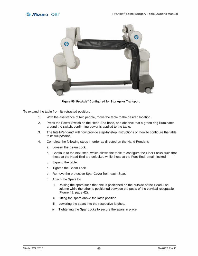
ProAxis® Spinal Surgery Table Owner’s Manual
46 Mizuho OSI 2016 NW0725 Rev K
Figure 55: ProAxis® Configured for Storage or Transport
To expand the table from its retracted position:
1. With the assistance of two people, move the table to the desired location.
2. Press the Power Switch on the Head-End base, and observe that a green ring illuminates around the switch, confirming power is applied to the table.
3. The IntelliPendant® will now provide step-by-step instructions on how to configure the table to its full position.
4. Complete the following steps in order as directed on the Hand Pendant:
a. Loosen the Beam Lock.
b. Continue to the next step, which allows the table to configure the Floor Locks such that those at the Head-End are unlocked while those at the Foot-End remain locked.
c. Expand the table.
d. Tighten the Beam Lock.
e. Remove the protective Spar Cover from each Spar.
f. Attach the Spars by:
i. Raising the spars such that one is positioned on the outside of the Head-End column while the other is positioned between the posts of the cervical receptacle (Figure 49, page 42).
ii. Lifting the spars above the latch position.
iii. Lowering the spars into the respective latches.
iv. Tightening the Spar Locks to secure the spars in place.

ProAxis® Spinal Surgery Table Owner’s Manual
47 Mizuho OSI 2016 NW0725 Rev K
5. Using the IntelliPendant®, lock the Floor Locks. Complete the Function Check (see Section 6).
6. Confirm Storage LED is no longer illuminated on the Auxiliary Control Panel.
NOTE: Upon expanding the table, the table will still be in the hinged state required for storage. To level the table top, install the Head-End Supine Top or the two rail mounts to activate the table’s hinge functionality. Then, press either the Hinge Down button or the Return to Level button until the Hinge Angle reads 0°.
4.7.6 Version Info
To access information on the table’s software version:
1. Press the Menu Soft Key on the IntelliPendant®.
2. Utilize the Down arrow Soft Key to select Version Info (Figure 56). Press the Soft Key that corresponds to the check mark.
3. Information on the table’s current software version will be displayed.
NOTE: Software version information will be primarily used by a service technician should it need to be accessed.
Figure 56: Version Info Menu Selection
4.8 Independent Monitoring System (IMS)
The ProAxis® Spinal Surgery Table includes an Independent Monitoring System that monitors the load on the table and notifies the user in the event the table is overloaded. The system works by monitoring the load on the Head-End plate to which the spars are attached. If the load exceeds the allowable amount for the maximum-weight patient, the system will notify the user through the use of an error message and table motion will be interrupted.
The table can be overloaded for three (3) reasons, any of which will be detected by the IMS and prevent motion of the table. No other conditions are monitored that will trigger the alarm system.
1. A patient whose weight is over the maximum weight limit is placed on the table.
2. Extreme external forces.
3. A loss of coordination between the Head-End and Foot-End, which can place additional load or tension on the table.
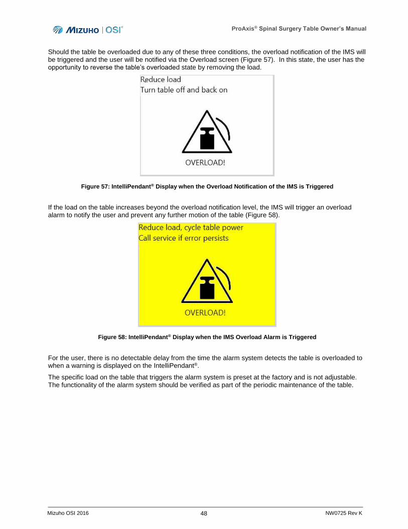
ProAxis® Spinal Surgery Table Owner’s Manual
48 Mizuho OSI 2016 NW0725 Rev K
Should the table be overloaded due to any of these three conditions, the overload notification of the IMS will be triggered and the user will be notified via the Overload screen (Figure 57). In this state, the user has the opportunity to reverse the table’s overloaded state by removing the load.
Figure 57: IntelliPendant® Display when the Overload Notification of the IMS is Triggered
If the load on the table increases beyond the overload notification level, the IMS will trigger an overload alarm to notify the user and prevent any further motion of the table (Figure 58).
Figure 58: IntelliPendant® Display when the IMS Overload Alarm is Triggered
For the user, there is no detectable delay from the time the alarm system detects the table is overloaded to when a warning is displayed on the IntelliPendant®.
The specific load on the table that triggers the alarm system is preset at the factory and is not adjustable. The functionality of the alarm system should be verified as part of the periodic maintenance of the table.
ProAxis® Spinal Surgery Table Owner’s Manual
49 Mizuho OSI 2016 NW0725 Rev K
5 Inspection
5.1 Acceptance and Transfer
1. Upon receipt of your ProAxis® Spinal Surgery Table, remove it from the shipping crate. Remove any protective wrapping or packaging. Visually inspect all surfaces for freight damage.
NOTE: Any freight damage must be reported to the freight carrier immediately upon delivery. It is the responsibility of the recipient to make freight damage claims.
2. Read the model number, serial number and confirm the power requirements on the manufacturer’s label located on the Foot-End column of the table.
3. Perform Function Check (refer to Section 6).
5.2 Pre-Procedure/Post-Procedure
Before and after each use of the ProAxis® Spinal Surgery Table, visually inspect all accessible areas, electrical cords, the table and all movable parts and components for possible damage that may adversely affect the proper operation of the table. Verify Beam Lock and Silver Spar Knobs are tightened. Examine the patient safety straps for any sign of wear or damage. Examine the covers of all pads for tears or other damage that might cause the pads to trap fluids or other contaminants. Damaged or defective products should not be used or processed. Contact Mizuho OSI Services for repair or replacement (refer to Section 13).
5.3 Semi-Annual Preventative Maintenance
A Semi-Annual Preventative Maintenance (PM) check (refer to Section 10.3) on your ProAxis® Spinal Surgery Table is required at least once every six (6) months.
To obtain the PM checklist call Mizuho OSI Services at 1-800-777-4674 within the USA or +1-510-429-1500 outside the USA.
5.4 Product Lifetime
At the time of delivery, your product fulfills existing regulations and standards; however, in spite of proper use, routine inspection, prescribed service, maintenance and repairs, the product is subject to aging and wear. Therefore, Mizuho OSI cannot guarantee the product’s safety after ten (10) years and recommends your product be taken out of service. For product warranty information, refer to Section 13.6 of this manual.
ProAxis® Spinal Surgery Table Owner’s Manual
50 Mizuho OSI 2016 NW0725 Rev K
6 Function Check NOTE: Perform all steps of the Function Check before every use of the ProAxis® Surgery Table.
For a complete definition of terms used in this procedure, please refer to the Glossary of Terms in Section 2.9.
1. Confirm the Beam Lock is tightened.
2. Confirm the silver Spar Locks at the Head-End of the table are tightened, securing the spars in place.
3. Connect the IntelliPendant® cable to the IntelliPendant® port on the Head-End column (Figure 5, page 14).
4. Plug the Power Cord into a properly grounded receptacle to use with AC power. Refer to the manufacturer’s label on the Foot-End column for input voltage requirements (Figure 10, page 18).
5. Press the Power Switch on the Head-End base, and observe that a green ring illuminates around the switch, confirming power is applied to the table.
6. If the AC power cable is not connected to an outlet with a protective earth ground, then the external ground stud should be connected to a protective earth ground (Figure 4, page 13).
7. If the table needs to be used under battery power due to AC outage, ensure that the battery has been properly charged as outlined in Section 12.3. Press the Power Switch on the Head-End base, and observe that a green ring illuminates around the switch confirming
power is applied to the table. The battery status symbol on the IntelliPendant® should be visible indicating a charged battery. If the battery status symbol on the IntelliPendant® is
the battery is not adequately charged and the table should only be used with AC power. To protect the patient, hospital staff, and the table from possible electrical hazards, an external ground cable connection is required between the external ground stud and protective earth ground when the table is in use under battery power (Figure 4, page 13).
8. Lockout mode: The ProAxis® Surgery Table motions are only operational if the Floor Locks are locked. The green indicator located on the Auxiliary Control Panel is illuminated and the Floor Lock symbol is visible on the IntelliPendant® display screen when the Floor Locks are completely engaged. Unlock the Floor Locks and verify that neither the IntelliPendant® nor the Auxiliary Control Panel functions operate except to activate the Floor Locks.
9. Complete a Floor Lock check using the Auxiliary Control Panel (Figure 15, page 21).
a. Press the Floor Lock button and observe the LED indicator is illuminated on the Auxiliary Panel and the Floor Lock symbol is visible on the IntelliPendant® display. The table is locked if it cannot be moved on its wheels.
b. Press the Floor Unlock button and observe the LED is no longer illuminated on the Auxiliary Panel and the Floor Unlock symbol is visible on the IntelliPendant® display. The table is unlocked if it can move on its wheels.

ProAxis® Spinal Surgery Table Owner’s Manual
51 Mizuho OSI 2016 NW0725 Rev K
c. Floor Lock Override Check:
i. With the Floor Locks unlocked, utilize the IntelliPendant® and select the Override Floor Locks setting.
ii. With the Override function active, utilize the Height Up, Height Down, Lateral Tilt Right and Left, or Trendelenburg/Reverse Trendelenburg buttons. These buttons should function without the Floor Locks being locked while the Override function is utilized.
10. IntelliPendant® Check:
a. Utilizing the IntelliPendant®, press the Floor Lock button. Observe on the Auxiliary Control Panel that the LED illuminates and that the Floor Lock symbol displays on the IntelliPendant® display after the floor locks are completely deployed and locked. Look under the Head-End and Foot-End base, and observe that all four feet have moved down and are in direct contact with the floor (Figure 16, page 21).
b. Press the Floor Unlock button. Observe that all four locking feet move up. Confirm the LED is not illuminated on the Auxiliary Control Panel and the Floor Unlock symbol displays on the IntelliPendant® display after the floor locks are completely retracted and unlocked. Look under the Head-End and Foot-End base and observe that all four feet have moved up and are not contacting the floor (Figure 16, page 21).
c. Repeat Step (a) to ensure the Floor Locks are fully engaged such that the rest of the table’s functionality may be tested.
d. Press and hold the Height Up button. Observe that the table top raises through its entire range. Observe the IntelliPendant® display, and confirm that the Height Up symbol is visible in the action display area of the screen. The number beside the Height Up symbol in the motion status area of the screen should be changing, corresponding to where the table top is within the height range.
e. Press and hold the Height Down button. Observe that the table top lowers through its entire range. Observe the IntelliPendant® display, and confirm that the Height Down symbol is visible in the action display area of the screen. The number beside the Height Down symbol in the motion status area of the screen should be changing, corresponding to where the table top is within the height range.
f. Press and hold the Reverse Trendelenburg button. Observe that the Foot-End of the table top moves down through its entire range. Observe the IntelliPendant® display, and confirm the Reverse Trendelenburg symbol is visible in the action display area of the screen. The number beside the Reverse Trendelenburg symbol in the motion status area of the screen should be changing, corresponding to where the table top is within the Reverse Trendelenburg range.
g. Press and hold the Trendelenburg button. Observe that the Head-End of the table top moves down through its entire range. Observe the IntelliPendant® display, and confirm that the Trendelenburg symbol is visible in the action display area of the screen. The number beside the Trendelenburg symbol in the motion status area of the screen should be changing, corresponding to where the table top is within the Trendelenburg range.
h. Press and hold the Lateral Tilt, Left button. Observe that the table top tilts to the left through its entire range. Observe the IntelliPendant® display, and confirm that the Lateral Tilt, Left symbol is visible in the action display area of the screen. The number beside the Lateral Tilt, Left symbol in the motion status area of the screen should be changing, corresponding to where the table top is within the Lateral Tilt range.
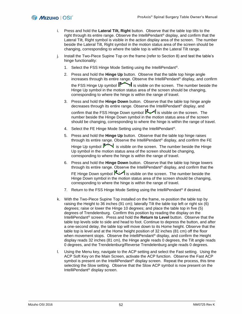
ProAxis® Spinal Surgery Table Owner’s Manual
52 Mizuho OSI 2016 NW0725 Rev K
i. Press and hold the Lateral Tilt, Right button. Observe that the table top tilts to the right through its entire range. Observe the IntelliPendant® display, and confirm that the Lateral Tilt, Right symbol is visible in the action display area of the screen. The number beside the Lateral Tilt, Right symbol in the motion status area of the screen should be changing, corresponding to where the table top is within the Lateral Tilt range.
j. Install the Two-Piece Supine Top on the frame (refer to Section 8) and test the table’s hinge functionality:
1. Select the FSS Hinge Mode Setting using the IntelliPendant®.
2. Press and hold the Hinge Up button. Observe that the table top hinge angle increases through its entire range. Observe the IntelliPendant® display, and confirm
the FSS Hinge Up symbol is visible on the screen. The number beside the Hinge Up symbol in the motion status area of the screen should be changing, corresponding to where the hinge is within the range of travel.
3. Press and hold the Hinge Down button. Observe that the table top hinge angle decreases through its entire range. Observe the IntelliPendant® display, and
confirm that the FSS Hinge Down symbol is visible on the screen. The number beside the Hinge Down symbol in the motion status area of the screen should be changing, corresponding to where the hinge is within the range of travel.
4. Select the FE Hinge Mode Setting using the IntelliPendant®.
5. Press and hold the Hinge Up button. Observe that the table top hinge raises through its entire range. Observe the IntelliPendant® display, and confirm the FE
Hinge Up symbol is visible on the screen. The number beside the Hinge Up symbol in the motion status area of the screen should be changing, corresponding to where the hinge is within the range of travel.
6. Press and hold the Hinge Down button. Observe that the table top hinge lowers through its entire range. Observe the IntelliPendant® display, and confirm that the
FE Hinge Down symbol is visible on the screen. The number beside the Hinge Down symbol in the motion status area of the screen should be changing, corresponding to where the hinge is within the range of travel.
7. Return to the FSS Hinge Mode Setting using the IntelliPendant® if desired.
k. With the Two-Piece Supine Top installed on the frame, re-position the table top by raising the Height to 36 inches (91 cm); laterally Tilt the table top left or right six (6) degrees; raise or lower the Hinge 10 degrees; and place the table top in five (5) degrees of Trendelenburg. Confirm this position by reading the display on the IntelliPendant® screen. Press and hold the Return to Level button. Observe that the table top levels side to side and head to foot. Continue to depress the button, and after a one-second delay, the table top will move down to its Home height. Observe that the table top is level and at the Home height position of 32 inches (81 cm) off the floor when movement stops. Observe the IntelliPendant® display, and confirm the Height display reads 32 inches (81 cm), the Hinge angle reads 0 degrees, the Tilt angle reads 0 degrees, and the Trendelenburg/Reverse Trendelenburg angle reads 0 degrees.
l. Using the Menu key, navigate to the ACP setting and select the Fast setting. Using the ACP Soft Key on the Main Screen, activate the ACP function. Observe the Fast ACP symbol is present on the IntelliPendant® display screen. Repeat the process, this time selecting the Slow setting. Observe that the Slow ACP symbol is now present on the IntelliPendant® display screen.
ProAxis® Spinal Surgery Table Owner’s Manual
53 Mizuho OSI 2016 NW0725 Rev K
11. Battery operation check:
a. Observe the Battery Status on the base of the Head-End column. If the LED is illuminated green - OK, then the battery is properly charged. Confirm that the Battery
Status icon on the IntelliPendant® is indicating the battery is fully charged and the table is ready to operate on battery power.
b. If the LED is illuminated red or the Battery Status icon on the IntelliPendant® is , the battery must be charged prior to using the table. To charge the battery, ensure the Power Cord is plugged into a functioning receptacle. The AC LED at the base of the Head-End column will illuminate green indicating that appropriate AC power is applied to the table. The table must remain plugged in for a minimum of three (3) hours to ensure sufficient charging of the battery to operate the table.
c. If the LED remains red and the Battery Status icon is still after three (3) hours, continue to charge the battery for up to 24 hours.
d. If the LED does not illuminate green-OK and the Battery Status icon does not reflect
after 24 hours, refer to Section 12.3 for servicing instructions.
NOTE: The table may be used with AC power even when the Battery Status icon is indicating the battery needs charging. Confirm the green AC power LED at the base of the Head-End column is illuminated.
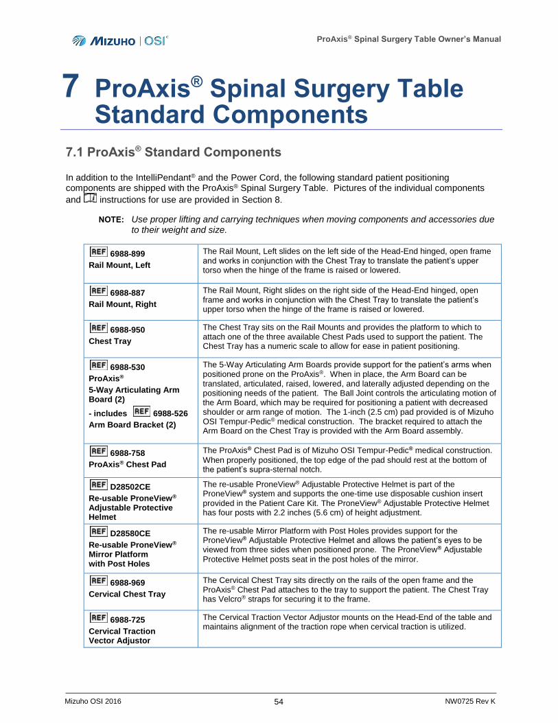
ProAxis® Spinal Surgery Table Owner’s Manual
54 Mizuho OSI 2016 NW0725 Rev K
7 ProAxis® Spinal Surgery Table Standard Components
7.1 ProAxis® Standard Components
In addition to the IntelliPendant® and the Power Cord, the following standard patient positioning components are shipped with the ProAxis® Spinal Surgery Table. Pictures of the individual components
and instructions for use are provided in Section 8.
NOTE: Use proper lifting and carrying techniques when moving components and accessories due to their weight and size.
6988-899
Rail Mount, Left
The Rail Mount, Left slides on the left side of the Head-End hinged, open frame and works in conjunction with the Chest Tray to translate the patient’s upper torso when the hinge of the frame is raised or lowered.
6988-887
Rail Mount, Right
The Rail Mount, Right slides on the right side of the Head-End hinged, open frame and works in conjunction with the Chest Tray to translate the patient’s upper torso when the hinge of the frame is raised or lowered.
6988-950
Chest Tray
The Chest Tray sits on the Rail Mounts and provides the platform to which to attach one of the three available Chest Pads used to support the patient. The Chest Tray has a numeric scale to allow for ease in patient positioning.
6988-530
ProAxis®
5-Way Articulating Arm Board (2)
- includes 6988-526
Arm Board Bracket (2)
The 5-Way Articulating Arm Boards provide support for the patient’s arms when positioned prone on the ProAxis®. When in place, the Arm Board can be translated, articulated, raised, lowered, and laterally adjusted depending on the positioning needs of the patient. The Ball Joint controls the articulating motion of the Arm Board, which may be required for positioning a patient with decreased shoulder or arm range of motion. The 1-inch (2.5 cm) pad provided is of Mizuho OSI Tempur-Pedic® medical construction. The bracket required to attach the Arm Board on the Chest Tray is provided with the Arm Board assembly.
6988-758
ProAxis® Chest Pad
The ProAxis® Chest Pad is of Mizuho OSI Tempur-Pedic® medical construction.
When properly positioned, the top edge of the pad should rest at the bottom of the patient’s supra-sternal notch.
D28502CE
Re-usable ProneView® Adjustable Protective Helmet
The re-usable ProneView® Adjustable Protective Helmet is part of the ProneView® system and supports the one-time use disposable cushion insert
provided in the Patient Care Kit. The ProneView® Adjustable Protective Helmet has four posts with 2.2 inches (5.6 cm) of height adjustment.
D28580CE
Re-usable ProneView® Mirror Platform with Post Holes
The re-usable Mirror Platform with Post Holes provides support for the ProneView® Adjustable Protective Helmet and allows the patient’s eyes to be viewed from three sides when positioned prone. The ProneView® Adjustable
Protective Helmet posts seat in the post holes of the mirror.
6988-969
Cervical Chest Tray
The Cervical Chest Tray sits directly on the rails of the open frame and the ProAxis® Chest Pad attaches to the tray to support the patient. The Chest Tray has Velcro® straps for securing it to the frame.
6988-725
Cervical Traction Vector Adjustor
The Cervical Traction Vector Adjustor mounts on the Head-End of the table and maintains alignment of the traction rope when cervical traction is utilized.
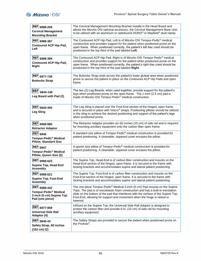
ProAxis® Spinal Surgery Table Owner’s Manual
55 Mizuho OSI 2016 NW0725 Rev K
6988-209
Cervical Management
Mounting Bracket
The Cervical Management Mounting Bracket installs in the Head Board and allows the Mizuho OSI optional accessory, the Cervical Management Base Unit, to be utilized with an aluminum or radiolucent DORO® or Mayfield® skull clamp.
6988-387
Contoured ACP Hip Pad, Left
The Contoured ACP Hip Pad, Left is of Mizuho OSI Tempur-Pedic® medical construction and provides support for the patient when positioned prone on the open frame. When positioned correctly, the patient’s left iliac crest should be positioned in the top third of the pad labeled Left.
6988-388
Contoured ACP Hip Pad, Right
The Contoured ACP Hip Pad, Right is of Mizuho OSI Tempur-Pedic® medical construction and provides support for the patient when positioned prone on the open frame. When positioned correctly, the patient’s right iliac crest should be positioned in the top third of the pad labeled Right.
6977-739
Buttocks Strap
The Buttocks Strap rests across the patient’s lower gluteal area when positioned prone to secure the patient in place on the Contoured ACP Hip Pads and open frame.
6844-148
Leg Board with Pad (2)
The two (2) Leg Boards, when used together, provide support for the patient’s legs when positioned prone on the open frame. The 1-inch (2.5 cm) pad is made of Mizuho OSI Tempur-Pedic® medical construction.
5840-450
Leg Sling
The Leg Sling is placed over the Foot-End section of the hinged, open frame and is secured in place with Velcro® straps. Positioning pillows should be utilized in the sling to achieve the desired positioning and support of the patient’s legs when positioned prone.
6988-880
Retractor Adaptor
The Retractor Adaptor provides six (6) inches (15 cm) of side rail and is required for mounting ancillary equipment onto the carbon fiber open frame.
6946
Tempur-Pedic® Medical Pillow, Standard Size
A standard size pillow of Tempur-Pedic® medical construction is provided for
patient positioning. A cleanable, zippered cover encases the pillow.
6947
Tempur-Pedic® Medical Pillow, Queen Size (2)
A queen size pillow of Tempur-Pedic® medical construction is provided for
patient positioning. A cleanable, zippered cover encases the pillow.
6988-623
Supine Top, Head-End Assembly
The Supine Top, Head-End is of carbon fiber construction and mounts on the Head-End section of the hinged, open frame. It is secured to the frame with locking brackets and accommodates supine and lateral patient positioning.
6988-621
Supine Top, Foot-End Assembly
The Supine Top, Foot-End is of carbon fiber construction and mounts on the Foot-End section of the hinged, open frame. It is secured to the frame with locking brackets and accommodates supine and lateral patient positioning.
6988-442
Tempur-Pedic® Medical 2-inch (5 cm) Supine Top Pad (one piece)
The one piece Tempur-Pedic® Medical 2-inch (5 cm) Pad mounts on the Supine
Tops. The pad is of viscoelastic foam construction and has a built-in translation slide on the bottom of the pad that interfaces with the surface of the Supine Top, Foot-End, allowing for support and movement when the hinge is raised or lowered.
6977-959
Universal Side Rail Adaptor (4)
Utilized on the Supine Top, the Universal Side Rail Adaptor is designed to protect the carbon fiber and provide 6-in. (15 cm) of side rail for mounting ancillary equipment.
5840-43
Safety Strap, 60 inches
(152 cm) (2)
The Safety Straps are provided to secure the patient when positioned prone on the ProAxis®.
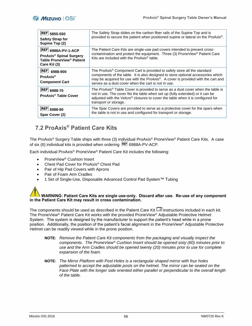
ProAxis® Spinal Surgery Table Owner’s Manual
56 Mizuho OSI 2016 NW0725 Rev K
5855-550
Safety Strap for Supine Top (2)
The Safety Strap slides on the carbon fiber rails of the Supine Top and is provided to secure the patient when positioned supine or lateral on the ProAxis®.
6988A-PV-1-ACP
ProAxis® Spinal Surgery Table ProneView® Patient Care Kit (3)
The Patient Care Kits are single-use pad covers intended to prevent cross-contamination and protect the equipment. Three (3) ProneView® Patient Care Kits are included with the ProAxis® table.
6988-900
ProAxis®
Component Cart
The ProAxis® Component Cart is provided to safely store all the standard components of the table. It is also designed to store optional accessories which may be acquired for use with the ProAxis®. A cover is provided with the cart and serves as a dust cover when the cart is not in use.
6988-70
ProAxis® Table Cover
The ProAxis® Table Cover is provided to serve as a dust cover when the table is not in use. The cover fits the table when set up (fully extended) or it can be adjusted with the Velcro® closures to cover the table when it is configured for transport or storage.
6988-90
Spar Cover (2)
The Spar Covers are provided to serve as a protective cover for the spars when the table is not in use and configured for transport or storage.
7.2 ProAxis® Patient Care Kits
The ProAxis® Surgery Table ships with three (3) individual ProAxis® ProneView® Patient Care Kits. A case
of six (6) individual kits is provided when ordering 6988A-PV-ACP.
Each individual ProAxis® ProneView® Patient Care Kit includes the following:
ProneView® Cushion Insert
Chest Pad Cover for ProAxis® Chest Pad
Pair of Hip Pad Covers with Aprons
Pair of Foam Arm Cradles
1 Set of Single-Use, Disposable Advanced Control Pad System™ Tubing
WARNING: Patient Care Kits are single use-only. Discard after use. Re-use of any component in the Patient Care Kit may result in cross contamination.
The components should be used as described in the Patient Care Kit instructions included in each kit. The ProneView® Patient Care Kit works with the provided ProneView® Adjustable Protective Helmet System. The system is designed by the manufacturer to support the patient’s head while in a prone position. Additionally, the position of the patient’s facial alignment in the ProneView® Adjustable Protective Helmet can be readily viewed while in the prone position.
NOTE: Remove the Patient Care Kit components from the packaging and visually inspect the components. The ProneView® Cushion Insert should be opened sixty (60) minutes prior to use and the Arm Cradles should be opened twenty (20) minutes prior to use for complete expansion of the foam.
NOTE: The Mirror Platform with Post Holes is a rectangular shaped mirror with four holes patterned to accept the adjustable posts on the helmet. The mirror can be seated on the Face Plate with the longer side oriented either parallel or perpendicular to the overall length of the table.
ProAxis® Spinal Surgery Table Owner’s Manual
57 Mizuho OSI 2016 NW0725 Rev K
8 Setup of ProAxis® Spinal Surgery Table for Surgical Procedures
NOTE: This device is intended for use by trained personnel. Prior to setup and use of the ProAxis® Spinal Surgery Table, ensure personnel have been trained. To schedule an in-service, please contact your domestic Mizuho OSI sales representative or call 1-800-777-4674 within the USA or +1-510-429-1500 outside the USA.
To prepare the ProAxis® Spinal Surgery Table for patient positioning, complete the following steps:
1. Connect the IntelliPendant® to the port on the Head-End column (Figure 19, page 24).
2. Press the Power Switch and observe that the switch illuminates with a green ring indicating that power is applied to the table.
3. Utilizing the IntelliPendant®, press the Floor Unlock button. Observe that the Floor Locks are completely retracted and the Floor Unlock symbol is visible on the display of the hand pendant (Figure 21, page 25).
4. With the assistance of a second person, move the table to where it will be used. One person should be located at the Head-End and the other person at the Foot-End of the table. Care should be taken to control the table when rolling.
WARNING: If the ProAxis® Spinal Surgery Table is allowed to roll too fast, it may be difficult to stop or turn. Impact of the table top with a stationary object may cause serious damage to the table top. If an impact does occur, the table must be visually inspected for damage and a Function Check must be performed (refer to Section 6). If damage is discovered or the table does not successfully complete the Function Check, call Mizuho OSI Services (refer to Section 13).
5. Orient the Head-End of the table in the room where the anesthesiologist work station is located.
6. Plug the Power Cord into a properly grounded receptacle. Refer to the manufacturer’s label on the Foot-End column for input voltage requirements (Figure 10, page 18). If the AC power cable is not connected to an outlet with a protective earth ground, then the external ground stud should be connected to a protective earth ground (Figure 10, page 18).
7. Using the IntelliPendant®, press the Floor Lock button. Observe that the Floor Lock symbol is visible on the hand pendant display (Figure 22, page 25).
8. Complete a Function Check with the IntelliPendant® (refer to Section 6).
NOTE: Perform all steps of the Function Check before every use of the ProAxis® Spinal Surgery Table.
NOTE: The ProAxis® Spinal Surgery Table is now ready for completing the setup of the patient components prior to patient transfer. Components have been designed to specifically mount on the carbon-fiber, trapezoidal frame or the Supine Top, while safely supporting the patient and not damaging the frame.

ProAxis® Spinal Surgery Table Owner’s Manual
58 Mizuho OSI 2016 NW0725 Rev K
Figure 59: ProAxis® Spinal Surgery Table Open Frame Ready for Setup
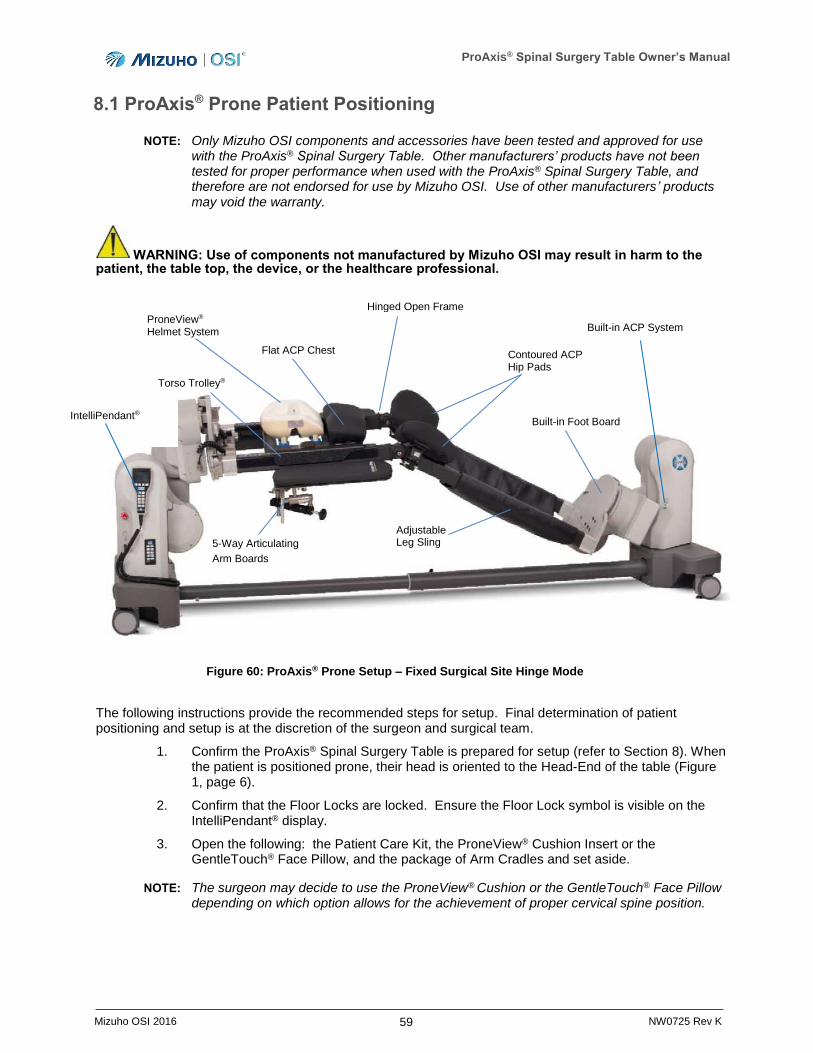
ProAxis® Spinal Surgery Table Owner’s Manual
59 Mizuho OSI 2016 NW0725 Rev K
8.1 ProAxis® Prone Patient Positioning
NOTE: Only Mizuho OSI components and accessories have been tested and approved for use with the ProAxis® Spinal Surgery Table. Other manufacturers’ products have not been tested for proper performance when used with the ProAxis® Spinal Surgery Table, and therefore are not endorsed for use by Mizuho OSI. Use of other manufacturers’ products may void the warranty.
WARNING: Use of components not manufactured by Mizuho OSI may result in harm to the patient, the table top, the device, or the healthcare professional.
Figure 60: ProAxis® Prone Setup – Fixed Surgical Site Hinge Mode
The following instructions provide the recommended steps for setup. Final determination of patient positioning and setup is at the discretion of the surgeon and surgical team.
1. Confirm the ProAxis® Spinal Surgery Table is prepared for setup (refer to Section 8). When the patient is positioned prone, their head is oriented to the Head-End of the table (Figure 1, page 6).
2. Confirm that the Floor Locks are locked. Ensure the Floor Lock symbol is visible on the IntelliPendant® display.
3. Open the following: the Patient Care Kit, the ProneView® Cushion Insert or the GentleTouch® Face Pillow, and the package of Arm Cradles and set aside.
NOTE: The surgeon may decide to use the ProneView® Cushion or the GentleTouch® Face Pillow depending on which option allows for the achievement of proper cervical spine position.
Torso Trolley®
Flat ACP Chest Pad
ProneView®
Helmet System
Hinged Open Frame
Contoured ACP Hip Pads
Built-in ACP System
Built-in Foot Board
5-Way Articulating
Arm Boards
Adjustable Leg Sling
IntelliPendant®

ProAxis® Spinal Surgery Table Owner’s Manual
60 Mizuho OSI 2016 NW0725 Rev K
4. Slide the Rail Mount, Right and Rail Mount, Left onto the corresponding Head-End sections of the Hinged Frame. The nipple will engage the bracket, locking the Rail Mount in place. To confirm, pull back on the Rail Mount; it should remain secure in the Hinged Frame bracket (Figure 61).
Figure 61: Installing the Rail Mount
5. Connect the cable connector extending from the Rail Mount, Right/Left to the port on the corresponding side of the Head-End Assembly. Align the pins of the cable connector with the port, insert and turn the locking collar to the right securing the pins in the port (Figure 62).
NOTE: To remove the Rail Mount, turn the locking collar to the left and pull the cable connector out of the port, disconnecting it from the Head-End Assembly. With the cable connector disconnected, depress the Black Tab on the frame while sliding the Rail Mount towards the hinge.
NOTE: When both rail mounts are connected, the Torso Trolley® drive pins may reposition to align properly.
Rail Mount, Slides into Bracket
Hinged Frame Bracket
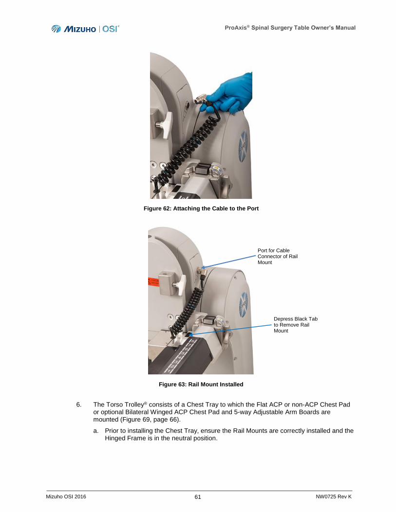
ProAxis® Spinal Surgery Table Owner’s Manual
61 Mizuho OSI 2016 NW0725 Rev K
Figure 62: Attaching the Cable to the Port
Figure 63: Rail Mount Installed
6. The Torso Trolley® consists of a Chest Tray to which the Flat ACP or non-ACP Chest Pad or optional Bilateral Winged ACP Chest Pad and 5-way Adjustable Arm Boards are mounted (Figure 69, page 66).
a. Prior to installing the Chest Tray, ensure the Rail Mounts are correctly installed and the Hinged Frame is in the neutral position.
Depress Black Tab to Remove Rail Mount
Port for Cable Connector of Rail Mount

ProAxis® Spinal Surgery Table Owner’s Manual
62 Mizuho OSI 2016 NW0725 Rev K
b. Confirm the display on the IntelliPendant® shows the Hinge, Trendelenburg, and Lateral Tilt angles are all 0° (Figure 22, page 25). If necessary, utilize the IntelliPendant® and press the Return to Level button to return the Hinged Frame to the neutral position.
Figure 64: Left and Right Rail Mounts Attached
7. To install the Chest Tray:
a. Orient the Chest Tray over the posts of the Rail Mounts and lower into place. The Chest Slide can be placed anywhere on the Rail Mounts that allows the posts to sit between the teeth of the Chest Slide (Figure 65).
b. Confirm the Chest Tray is not placed on the rails at a point lower than Position 1 on the Rail Mounts in order to ensure the Chest Tray is properly engaged.
NOTE: When mounting the Chest Tray onto the rails, ensure the yellow strip on each of the Rail Mounts is not visible. Appearance of the yellow strips indicates that the Chest Tray is not properly engaged with Rail Mounts.
WARNING: Visibility of the yellow strips on the Rail Mounts indicate that Chest Tray is not properly engaged with the Rail Mounts, which will prevent it from sliding correctly during hinge motion. Failure to ensure the Chest Tray is correctly mounted may result in harm to the patient or the device.
c. The Chest Tray may be moved up or down the length of the Rail Mounts by simultaneously squeezing the grips of the Chest Tray and moving it to the desired location. Release both grips to lock the Chest Tray into place.
Yellow Strip
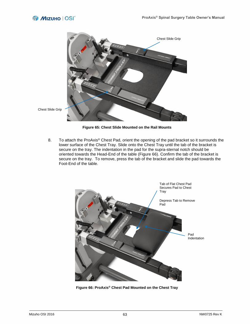
ProAxis® Spinal Surgery Table Owner’s Manual
63 Mizuho OSI 2016 NW0725 Rev K
Figure 65: Chest Slide Mounted on the Rail Mounts
8. To attach the ProAxis® Chest Pad, orient the opening of the pad bracket so it surrounds the lower surface of the Chest Tray. Slide onto the Chest Tray until the tab of the bracket is secure on the tray. The indentation in the pad for the supra-sternal notch should be oriented towards the Head-End of the table (Figure 66). Confirm the tab of the bracket is secure on the tray. To remove, press the tab of the bracket and slide the pad towards the Foot-End of the table.
Figure 66: ProAxis® Chest Pad Mounted on the Chest Tray
Chest Slide Grip
Chest Slide Grip
Pad Indentation
Tab of Flat Chest Pad Secures Pad to Chest Tray
Depress Tab to Remove Pad
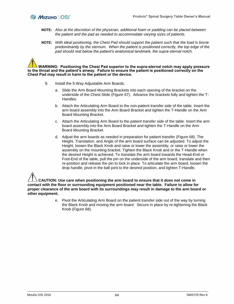
ProAxis® Spinal Surgery Table Owner’s Manual
64 Mizuho OSI 2016 NW0725 Rev K
NOTE: Also at the discretion of the physician, additional foam or padding can be placed between
the patient and the pad as needed to accommodate varying sizes of patients.
NOTE: With ideal positioning, the Chest Pad should support the patient such that the load is borne predominantly by the sternum. When the patient is positioned correctly, the top edge of the pad should rest below the patient’s anatomical landmark, the supra-sternal notch.
WARNING: Positioning the Chest Pad superior to the supra-sternal notch may apply pressure to the throat and the patient’s airway. Failure to ensure the patient is positioned correctly on the Chest Pad may result in harm to the patient or the device.
9. Install the 5-Way Adjustable Arm Boards.
a. Slide the Arm Board Mounting Brackets into each opening of the bracket on the underside of the Chest Slide (Figure 67). Advance the brackets fully and tighten the T- Handles.
b. Attach the Articulating Arm Board to the non-patient transfer side of the table. Insert the arm board assembly into the Arm Board Bracket and tighten the T-Handle on the Arm Board Mounting Bracket.
c. Attach the Articulating Arm Board to the patient transfer side of the table. Insert the arm board assembly into the Arm Board Bracket and tighten the T-Handle on the Arm Board Mounting Bracket.
d. Adjust the arm boards as needed in preparation for patient transfer (Figure 68). The Height, Translation, and Angle of the arm board surface can be adjusted. To adjust the Height, loosen the Black Knob and raise or lower the assembly, or raise or lower the assembly on the mounting bracket. Tighten the Black Knob and or the T-Handle when the desired Height is achieved. To translate the arm board towards the Head-End or Foot-End of the table, pull the pin on the underside of the arm board, translate and then re-position and release the pin to lock in place. To articulate the arm board, loosen the drop handle, pivot in the ball joint to the desired position, and tighten T-Handle.
CAUTION: Use care when positioning the arm board to ensure that it does not come in contact with the floor or surrounding equipment positioned near the table. Failure to allow for proper clearance of the arm board with its surroundings may result in damage to the arm board or other equipment.
e. Pivot the Articulating Arm Board on the patient transfer side out of the way by turning the Black Knob and moving the arm board. Secure in place by re-tightening the Black Knob (Figure 68).
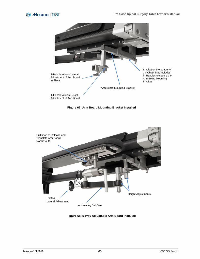
ProAxis® Spinal Surgery Table Owner’s Manual
65 Mizuho OSI 2016 NW0725 Rev K
Figure 67: Arm Board Mounting Bracket Installed
Figure 68: 5-Way Adjustable Arm Board Installed
Pull knob to Release and Translate Arm Board North/South.
Bracket on the bottom of the Chest Tray includes T- Handles to secure the Arm Board Mounting Bracket.
T-Handle Allows Lateral Adjustment of Arm Board in Place
T-Handle Allows Height Adjustment of Arm Board
Arm Board Mounting Bracket
Height Adjustments
Articulating Ball Joint
Pivot &
Lateral Adjustment
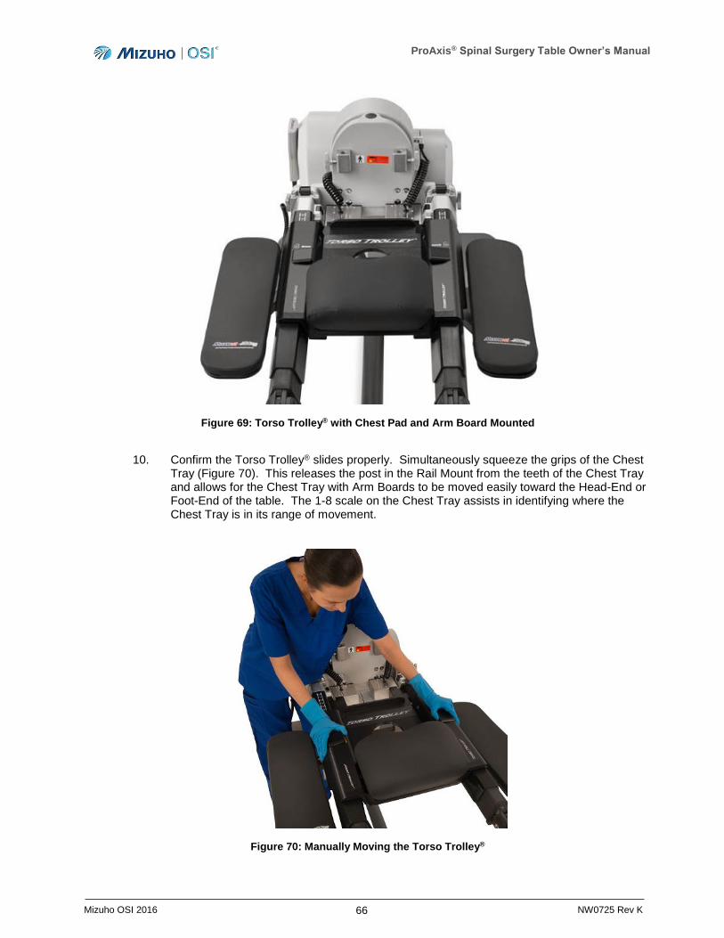
ProAxis® Spinal Surgery Table Owner’s Manual
66 Mizuho OSI 2016 NW0725 Rev K
Figure 69: Torso Trolley® with Chest Pad and Arm Board Mounted
10. Confirm the Torso Trolley® slides properly. Simultaneously squeeze the grips of the Chest Tray (Figure 70). This releases the post in the Rail Mount from the teeth of the Chest Tray and allows for the Chest Tray with Arm Boards to be moved easily toward the Head-End or Foot-End of the table. The 1-8 scale on the Chest Tray assists in identifying where the Chest Tray is in its range of movement.
Figure 70: Manually Moving the Torso Trolley®
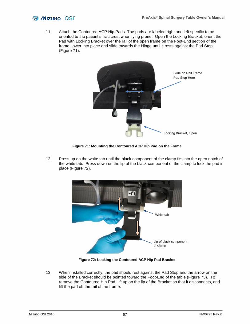
ProAxis® Spinal Surgery Table Owner’s Manual
67 Mizuho OSI 2016 NW0725 Rev K
11. Attach the Contoured ACP Hip Pads. The pads are labeled right and left specific to be oriented to the patient’s iliac crest when lying prone. Open the Locking Bracket, orient the Pad with Locking Bracket over the rail of the open frame on the Foot-End section of the frame, lower into place and slide towards the Hinge until it rests against the Pad Stop (Figure 71).
Figure 71: Mounting the Contoured ACP Hip Pad on the Frame
12. Press up on the white tab until the black component of the clamp fits into the open notch of the white tab. Press down on the lip of the black component of the clamp to lock the pad in place (Figure 72).
Figure 72: Locking the Contoured ACP Hip Pad Bracket
13. When installed correctly, the pad should rest against the Pad Stop and the arrow on the side of the Bracket should be pointed toward the Foot-End of the table (Figure 73). To remove the Contoured Hip Pad, lift up on the lip of the Bracket so that it disconnects, and lift the pad off the rail of the frame.
Slide on Rail Frame
Pad Stop Here
Locking Bracket, Open
White tab
Lip of black component of clamp
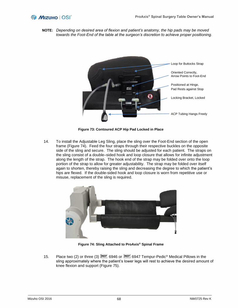
ProAxis® Spinal Surgery Table Owner’s Manual
68 Mizuho OSI 2016 NW0725 Rev K
NOTE: Depending on desired area of flexion and patient’s anatomy, the hip pads may be moved towards the Foot-End of the table at the surgeon’s discretion to achieve proper positioning.
Figure 73: Contoured ACP Hip Pad Locked in Place
14. To install the Adjustable Leg Sling, place the sling over the Foot-End section of the open frame (Figure 74). Feed the four straps through their respective buckles on the opposite side of the sling and secure. The sling should be adjusted for each patient. The straps on the sling consist of a double–sided hook and loop closure that allows for infinite adjustment along the length of the strap. The hook end of the strap may be folded over onto the loop portion of the strap to allow for greater adjustability. The strap may be folded over itself again to shorten, thereby raising the sling and decreasing the degree to which the patient’s hips are flexed. If the double-sided hook and loop closure is worn from repetitive use or misuse, replacement of the sling is required.
Figure 74: Sling Attached to ProAxis® Spinal Frame
15. Place two (2) or three (3) 6946 or 6947 Tempur-Pedic® Medical Pillows in the sling approximately where the patient’s lower legs will rest to achieve the desired amount of knee flexion and support (Figure 75).
Loop for Buttocks Strap
Oriented Correctly, Arrow Points to Foot-End
Positioned at Hinge,
Pad Rests against Stop
Locking Bracket, Locked
ACP Tubing Hangs Freely
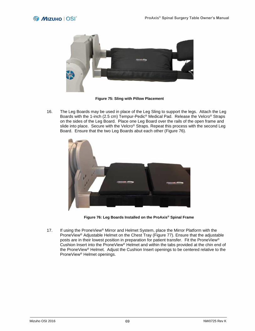
ProAxis® Spinal Surgery Table Owner’s Manual
69 Mizuho OSI 2016 NW0725 Rev K
Figure 75: Sling with Pillow Placement
16. The Leg Boards may be used in place of the Leg Sling to support the legs. Attach the Leg Boards with the 1-inch (2.5 cm) Tempur-Pedic® Medical Pad. Release the Velcro® Straps on the sides of the Leg Board. Place one Leg Board over the rails of the open frame and slide into place. Secure with the Velcro® Straps. Repeat this process with the second Leg Board. Ensure that the two Leg Boards abut each other (Figure 76).
Figure 76: Leg Boards Installed on the ProAxis® Spinal Frame
17. If using the ProneView® Mirror and Helmet System, place the Mirror Platform with the ProneView® Adjustable Helmet on the Chest Tray (Figure 77). Ensure that the adjustable posts are in their lowest position in preparation for patient transfer. Fit the ProneView® Cushion Insert into the ProneView® Helmet and within the tabs provided at the chin end of the ProneView® Helmet. Adjust the Cushion Insert openings to be centered relative to the ProneView® Helmet openings.
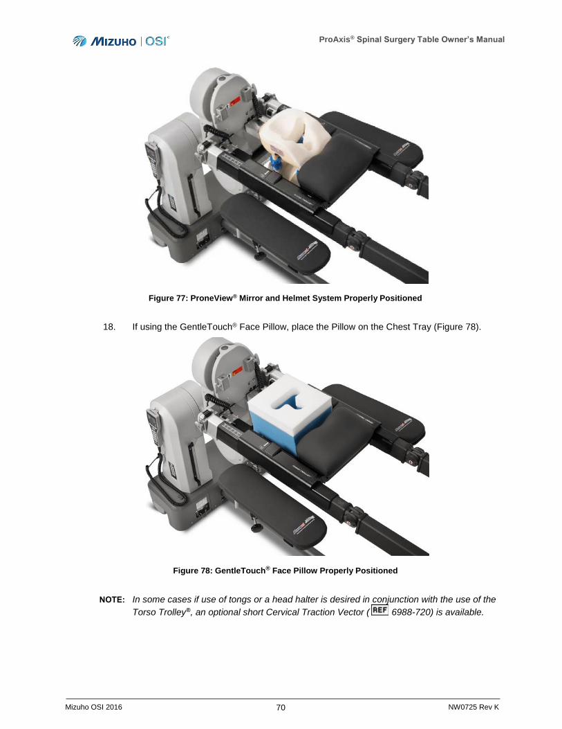
ProAxis® Spinal Surgery Table Owner’s Manual
70 Mizuho OSI 2016 NW0725 Rev K
Figure 77: ProneView® Mirror and Helmet System Properly Positioned
18. If using the GentleTouch® Face Pillow, place the Pillow on the Chest Tray (Figure 78).
Figure 78: GentleTouch® Face Pillow Properly Positioned
NOTE: In some cases if use of tongs or a head halter is desired in conjunction with the use of the
Torso Trolley®, an optional short Cervical Traction Vector ( 6988-720) is available.
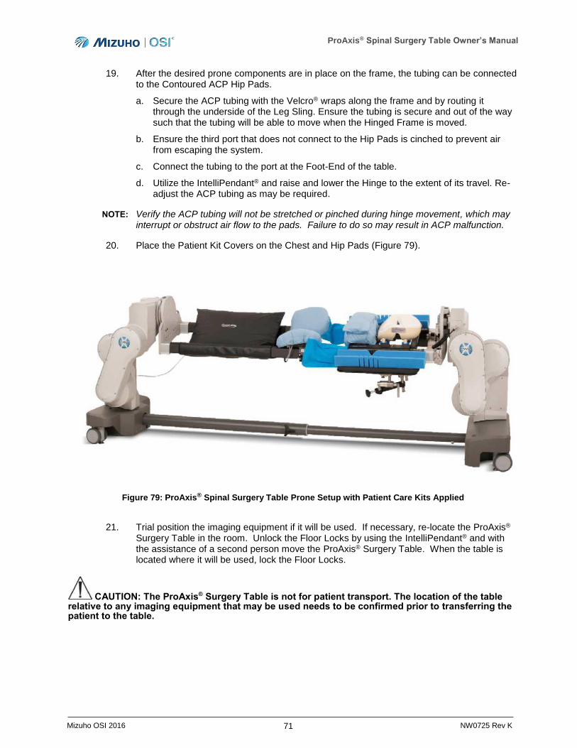
ProAxis® Spinal Surgery Table Owner’s Manual
71 Mizuho OSI 2016 NW0725 Rev K
19. After the desired prone components are in place on the frame, the tubing can be connected to the Contoured ACP Hip Pads.
a. Secure the ACP tubing with the Velcro® wraps along the frame and by routing it through the underside of the Leg Sling. Ensure the tubing is secure and out of the way such that the tubing will be able to move when the Hinged Frame is moved.
b. Ensure the third port that does not connect to the Hip Pads is cinched to prevent air from escaping the system.
c. Connect the tubing to the port at the Foot-End of the table.
d. Utilize the IntelliPendant® and raise and lower the Hinge to the extent of its travel. Re-adjust the ACP tubing as may be required.
NOTE: Verify the ACP tubing will not be stretched or pinched during hinge movement, which may interrupt or obstruct air flow to the pads. Failure to do so may result in ACP malfunction.
20. Place the Patient Kit Covers on the Chest and Hip Pads (Figure 79).
Figure 79: ProAxis® Spinal Surgery Table Prone Setup with Patient Care Kits Applied
21. Trial position the imaging equipment if it will be used. If necessary, re-locate the ProAxis® Surgery Table in the room. Unlock the Floor Locks by using the IntelliPendant® and with the assistance of a second person move the ProAxis® Surgery Table. When the table is located where it will be used, lock the Floor Locks.
CAUTION: The ProAxis® Surgery Table is not for patient transport. The location of the table relative to any imaging equipment that may be used needs to be confirmed prior to transferring the patient to the table.
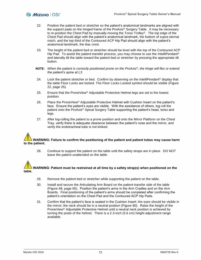
ProAxis® Spinal Surgery Table Owner’s Manual
72 Mizuho OSI 2016 NW0725 Rev K
22. Position the patient bed or stretcher so the patient’s anatomical landmarks are aligned with the support pads on the hinged frame of the ProAxis® Surgery Table. It may be necessary to re-position the Chest Pad by manually moving the Torso Trolley®. The top edge of the Chest Pad should align with the patient’s anatomical landmark, the bottom of supra-sternal notch, and the top third of the Contoured ACP Hip Pad should align with the patient’s anatomical landmark, the iliac crest.
23. The height of the patient bed or stretcher should be level with the top of the Contoured ACP Hip Pad. To assist the patient transfer process, you may choose to use the IntelliPendant® and laterally tilt the table toward the patient bed or stretcher by pressing the appropriate tilt button.
NOTE: When the patient is correctly positioned prone on the ProAxis®, the hinge will flex or extend the patient’s spine at L3.
24. Lock the patient stretcher or bed. Confirm by observing on the IntelliPendant® display that the table Floor Locks are locked. The Floor Locks Locked symbol should be visible (Figure 22, page 25).
25. Ensure that the ProneView® Adjustable Protective Helmet legs are set to the lowest position.
26. Place the ProneView® Adjustable Protective Helmet with Cushion Insert on the patient’s face. Ensure the patient’s eyes are visible. With the assistance of others, log-roll the patient onto the ProAxis® Spinal Surgery Table supporting the patient’s head, torso and legs.
27. After log-rolling the patient to a prone position and onto the Mirror Platform on the Chest Tray, verify there is adequate clearance between the patient’s nose and the mirror, and verify the endotracheal tube is not kinked.
WARNING: Failure to confirm the positioning of the patient and patient tubes may cause harm to the patient.
28. Continue to support the patient on the table until the safety straps are in place. DO NOT leave the patient unattended on the table.
WARNING: Patient must be restrained at all time by a safety strap(s) when positioned on the table.
29. Remove the patient bed or stretcher while supporting the patient on the table.
30. Install and secure the Articulating Arm Board on the patient transfer side of the table (Figure 68, page 65). Position the patient’s arms in the Arm Cradles and on the Arm Boards. Final positioning of the patient’s arms should be completed after confirming the patient’s orientation on the Chest Pad and the Contoured ACP Hip Pads.
31. Confirm that the patient’s face is seated in the Cushion Insert; the eyes should be visible in the mirror; the neck should be in a neutral position (Figure 80). Raise the height of the ProneView® Adjustable Protective Helmet until a neutral neck position is achieved by turning the posts of the helmet. There is a 2.3-inch (5.6 cm) height adjustment range available.
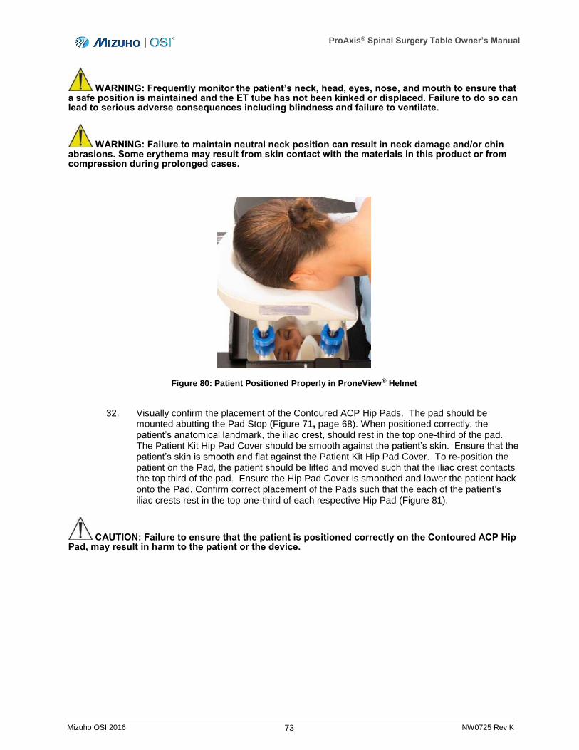
ProAxis® Spinal Surgery Table Owner’s Manual
73 Mizuho OSI 2016 NW0725 Rev K
WARNING: Frequently monitor the patient’s neck, head, eyes, nose, and mouth to ensure that a safe position is maintained and the ET tube has not been kinked or displaced. Failure to do so can lead to serious adverse consequences including blindness and failure to ventilate.
WARNING: Failure to maintain neutral neck position can result in neck damage and/or chin abrasions. Some erythema may result from skin contact with the materials in this product or from compression during prolonged cases.
Figure 80: Patient Positioned Properly in ProneView® Helmet
32. Visually confirm the placement of the Contoured ACP Hip Pads. The pad should be mounted abutting the Pad Stop (Figure 71, page 68). When positioned correctly, the patient’s anatomical landmark, the iliac crest, should rest in the top one-third of the pad. The Patient Kit Hip Pad Cover should be smooth against the patient’s skin. Ensure that the patient’s skin is smooth and flat against the Patient Kit Hip Pad Cover. To re-position the patient on the Pad, the patient should be lifted and moved such that the iliac crest contacts the top third of the pad. Ensure the Hip Pad Cover is smoothed and lower the patient back onto the Pad. Confirm correct placement of the Pads such that the each of the patient’s iliac crests rest in the top one-third of each respective Hip Pad (Figure 81).
CAUTION: Failure to ensure that the patient is positioned correctly on the Contoured ACP Hip Pad, may result in harm to the patient or the device.
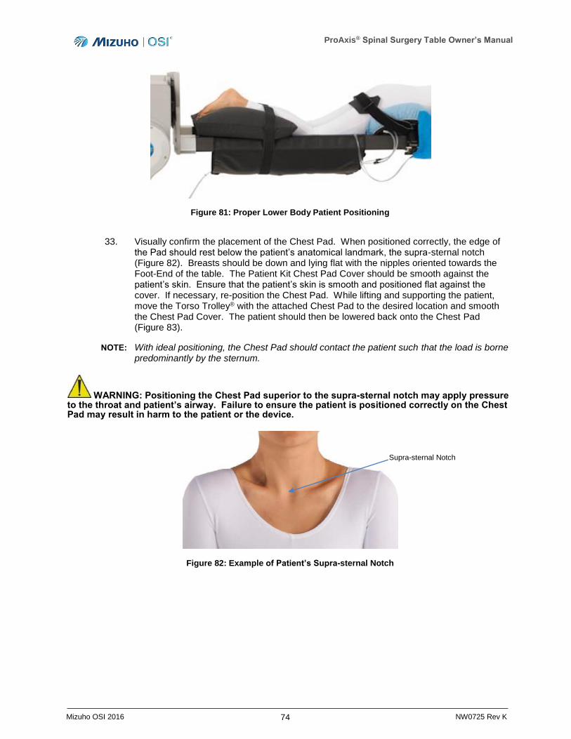
ProAxis® Spinal Surgery Table Owner’s Manual
74 Mizuho OSI 2016 NW0725 Rev K
Figure 81: Proper Lower Body Patient Positioning
33. Visually confirm the placement of the Chest Pad. When positioned correctly, the edge of the Pad should rest below the patient’s anatomical landmark, the supra-sternal notch (Figure 82). Breasts should be down and lying flat with the nipples oriented towards the Foot-End of the table. The Patient Kit Chest Pad Cover should be smooth against the patient’s skin. Ensure that the patient’s skin is smooth and positioned flat against the cover. If necessary, re-position the Chest Pad. While lifting and supporting the patient, move the Torso Trolley® with the attached Chest Pad to the desired location and smooth the Chest Pad Cover. The patient should then be lowered back onto the Chest Pad (Figure 83).
NOTE: With ideal positioning, the Chest Pad should contact the patient such that the load is borne predominantly by the sternum.
WARNING: Positioning the Chest Pad superior to the supra-sternal notch may apply pressure to the throat and patient’s airway. Failure to ensure the patient is positioned correctly on the Chest Pad may result in harm to the patient or the device.
Figure 82: Example of Patient’s Supra-sternal Notch
Supra-sternal Notch
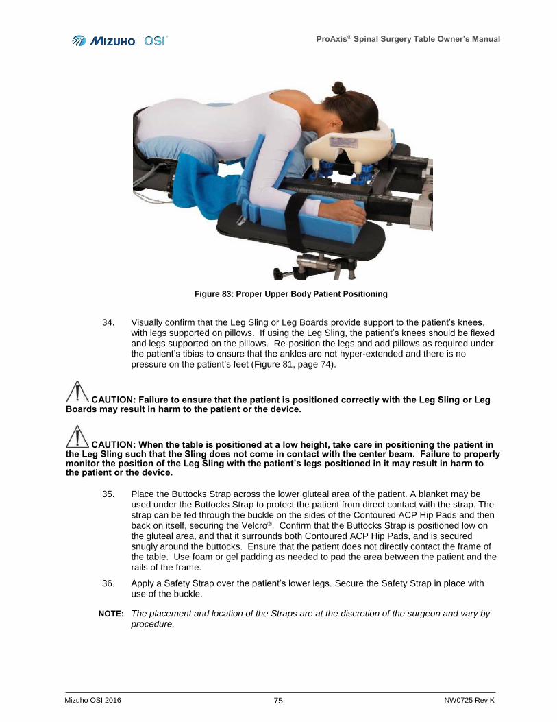
ProAxis® Spinal Surgery Table Owner’s Manual
75 Mizuho OSI 2016 NW0725 Rev K
Figure 83: Proper Upper Body Patient Positioning
34. Visually confirm that the Leg Sling or Leg Boards provide support to the patient’s knees, with legs supported on pillows. If using the Leg Sling, the patient’s knees should be flexed and legs supported on the pillows. Re-position the legs and add pillows as required under the patient’s tibias to ensure that the ankles are not hyper-extended and there is no pressure on the patient’s feet (Figure 81, page 74).
CAUTION: Failure to ensure that the patient is positioned correctly with the Leg Sling or Leg Boards may result in harm to the patient or the device.
CAUTION: When the table is positioned at a low height, take care in positioning the patient in the Leg Sling such that the Sling does not come in contact with the center beam. Failure to properly monitor the position of the Leg Sling with the patient’s legs positioned in it may result in harm to the patient or the device.
35. Place the Buttocks Strap across the lower gluteal area of the patient. A blanket may be used under the Buttocks Strap to protect the patient from direct contact with the strap. The strap can be fed through the buckle on the sides of the Contoured ACP Hip Pads and then back on itself, securing the Velcro®. Confirm that the Buttocks Strap is positioned low on the gluteal area, and that it surrounds both Contoured ACP Hip Pads, and is secured snugly around the buttocks. Ensure that the patient does not directly contact the frame of the table. Use foam or gel padding as needed to pad the area between the patient and the rails of the frame.
36. Apply a Safety Strap over the patient’s lower legs. Secure the Safety Strap in place with use of the buckle.
NOTE: The placement and location of the Straps are at the discretion of the surgeon and vary by procedure.
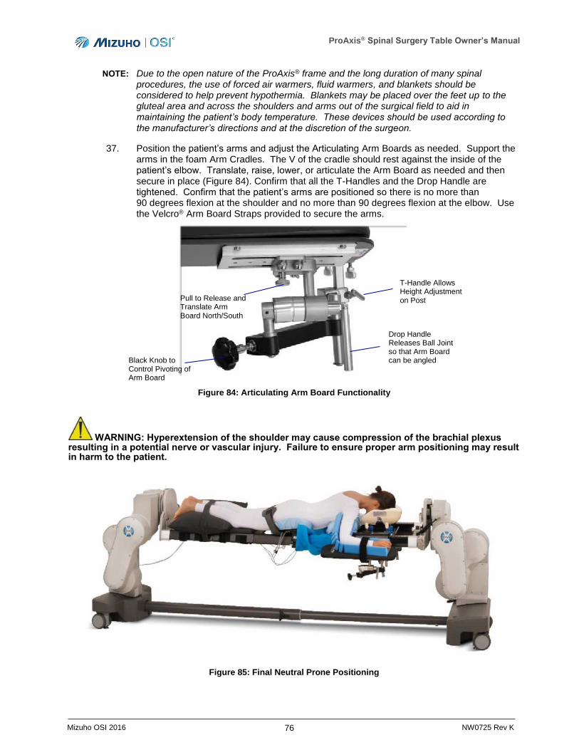
ProAxis® Spinal Surgery Table Owner’s Manual
76 Mizuho OSI 2016 NW0725 Rev K
NOTE: Due to the open nature of the ProAxis® frame and the long duration of many spinal procedures, the use of forced air warmers, fluid warmers, and blankets should be considered to help prevent hypothermia. Blankets may be placed over the feet up to the gluteal area and across the shoulders and arms out of the surgical field to aid in maintaining the patient’s body temperature. These devices should be used according to the manufacturer’s directions and at the discretion of the surgeon.
37. Position the patient’s arms and adjust the Articulating Arm Boards as needed. Support the arms in the foam Arm Cradles. The V of the cradle should rest against the inside of the patient’s elbow. Translate, raise, lower, or articulate the Arm Board as needed and then secure in place (Figure 84). Confirm that all the T-Handles and the Drop Handle are tightened. Confirm that the patient’s arms are positioned so there is no more than 90 degrees flexion at the shoulder and no more than 90 degrees flexion at the elbow. Use the Velcro® Arm Board Straps provided to secure the arms.
Figure 84: Articulating Arm Board Functionality
WARNING: Hyperextension of the shoulder may cause compression of the brachial plexus resulting in a potential nerve or vascular injury. Failure to ensure proper arm positioning may result in harm to the patient.
Figure 85: Final Neutral Prone Positioning
Pull to Release and Translate Arm Board North/South
Black Knob to Control Pivoting of Arm Board
Drop Handle Releases Ball Joint so that Arm Board can be angled
T-Handle Allows Height Adjustment on Post

ProAxis® Spinal Surgery Table Owner’s Manual
77 Mizuho OSI 2016 NW0725 Rev K
WARNING: Proper pre-operative and intra-operative procedures must be followed to prevent venous stasis and pooling, pressure sore development, neuropathy, improper electrosurgical tissue grounding, hypertension/hypotension, and hypothermia.
CAUTION: Use care and monitor the patient when changing the position of the ProAxis® Surgery Table (Height Up/Down, Hinge Up/Down, Trendelenburg/Reverse Trendelenburg, and Lateral Roll) to ensure that the patient or table does not interfere with other equipment and the components and accessories have proper clearance in relation to the surrounding areas. Failure to do so may cause harm to the patient or device.
38. Confirm that the patient is properly positioned. If a Retractor Adaptor is required to mount auxiliary equipment, mount it on the rail frame. Open the Adaptor by turning the black knob and releasing the bottom of the Adaptor. Place the Adaptor around the frame, align the black knob, turn to tighten and secure the Adaptor in place (Figure 86). Ensure that the patient does not directly contact the Retractor Adaptor. Use foam or gel padding as needed to pad the area between the patient and the Adaptor.
Figure 86: Retractor Adaptor Mounted on Carbon Fiber Rail
WARNING: Only the metal Retractor Adaptor may be positioned in the area above the hinge and below the rail mounts. Use of the optional Radiolucent Retractor Adaptor at this location results in a pinch point when using the hinge capabilities of the table, which may cause harm to the patient or the device.
NOTE: Use of the Radiolucent Retractor Adaptor at any location below the Hip Pads is allowed when the hinge functionality of the table is engaged. The Radiolucent Retractor Adaptor can also be used above the hinge when the table is configured for cervical and the hinge functionality is deactivated.
39. Refer to Section 4 for instructions on how to utilize the IntelliPendant® and operate the table.
Retractor Adaptor
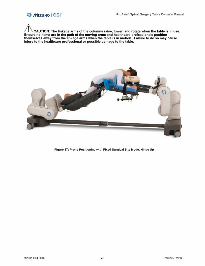
ProAxis® Spinal Surgery Table Owner’s Manual
78 Mizuho OSI 2016 NW0725 Rev K
CAUTION: The linkage arms of the columns raise, lower, and rotate when the table is in use. Ensure no items are in the path of the moving arms and healthcare professionals position themselves away from the linkage arms when the table is in motion. Failure to do so may cause injury to the healthcare professional or possible damage to the table.
Figure 87: Prone Positioning with Fixed Surgical Site Mode, Hinge Up
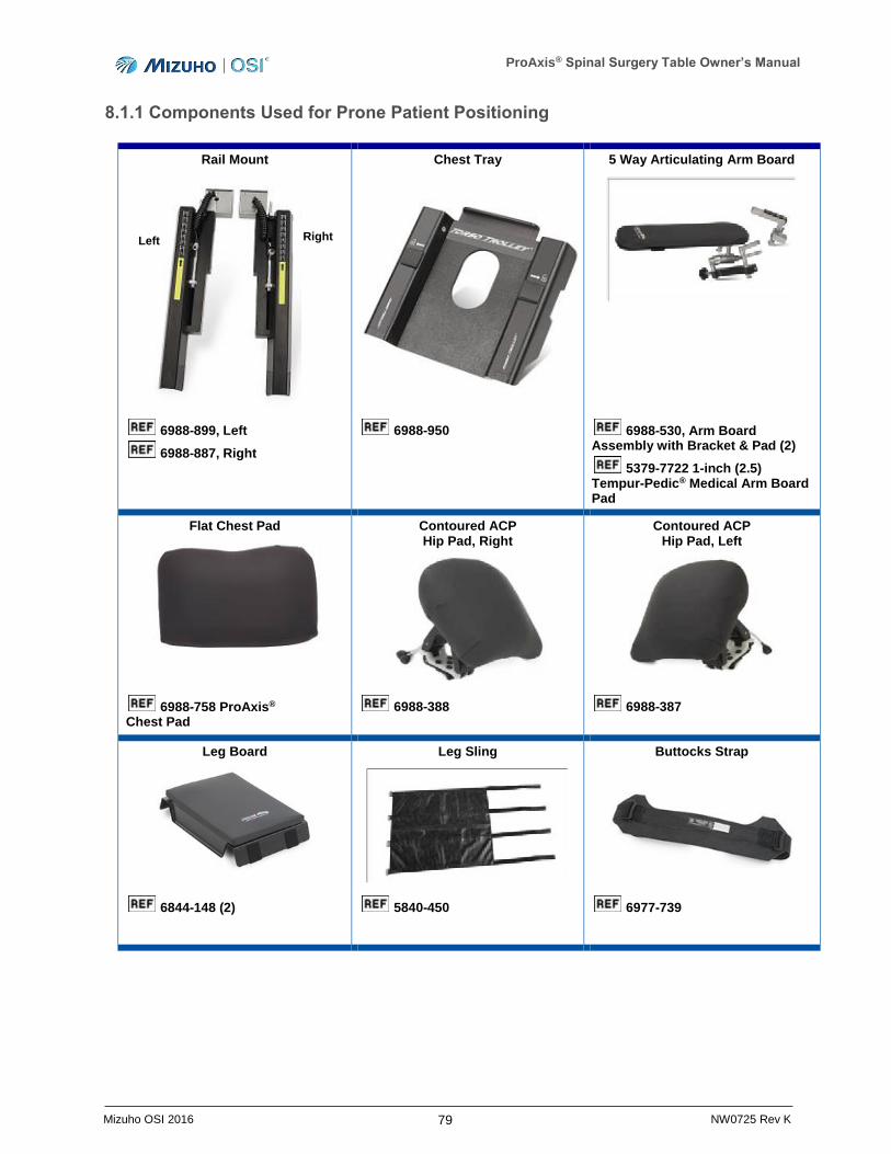
ProAxis® Spinal Surgery Table Owner’s Manual
79 Mizuho OSI 2016 NW0725 Rev K
8.1.1 Components Used for Prone Patient Positioning
Rail Mount
Chest Tray
5 Way Articulating Arm Board
6988-899, Left
6988-887, Right
6988-950
6988-530, Arm Board Assembly with Bracket & Pad (2)
5379-7722 1-inch (2.5) Tempur-Pedic® Medical Arm Board Pad
Flat Chest Pad
Contoured ACP Hip Pad, Right
Contoured ACP Hip Pad, Left
6988-758 ProAxis® Chest Pad
6988-388 6988-387
Leg Board
Leg Sling
Buttocks Strap
6844-148 (2) 5840-450 6977-739
Left Right
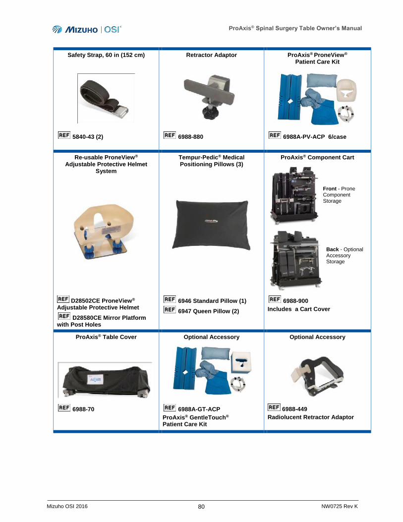
ProAxis® Spinal Surgery Table Owner’s Manual
80 Mizuho OSI 2016 NW0725 Rev K
Safety Strap, 60 in (152 cm)
Retractor Adaptor
ProAxis® ProneView® Patient Care Kit
5840-43 (2)
6988-880
6988A-PV-ACP 6/case
Re-usable ProneView® Adjustable Protective Helmet
System
Tempur-Pedic® Medical Positioning Pillows (3)
ProAxis® Component Cart
D28502CE ProneView® Adjustable Protective Helmet
D28580CE Mirror Platform with Post Holes
6946 Standard Pillow (1)
6947 Queen Pillow (2)
6988-900
Includes a Cart Cover
ProAxis® Table Cover
Optional Accessory
Optional Accessory
6988-70
6988A-GT-ACP
ProAxis® GentleTouch® Patient Care Kit
6988-449
Radiolucent Retractor Adaptor
Front - Prone Component Storage
Back - Optional Accessory Storage
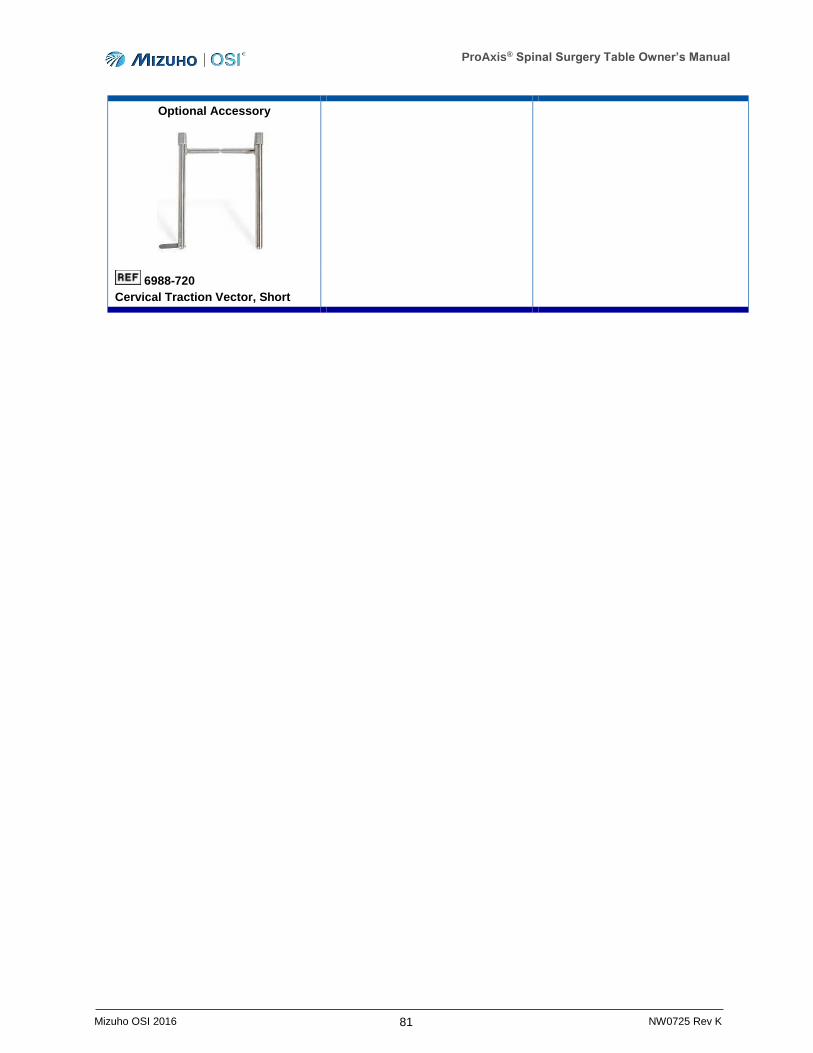
ProAxis® Spinal Surgery Table Owner’s Manual
81 Mizuho OSI 2016 NW0725 Rev K
Optional Accessory
6988-720
Cervical Traction Vector, Short
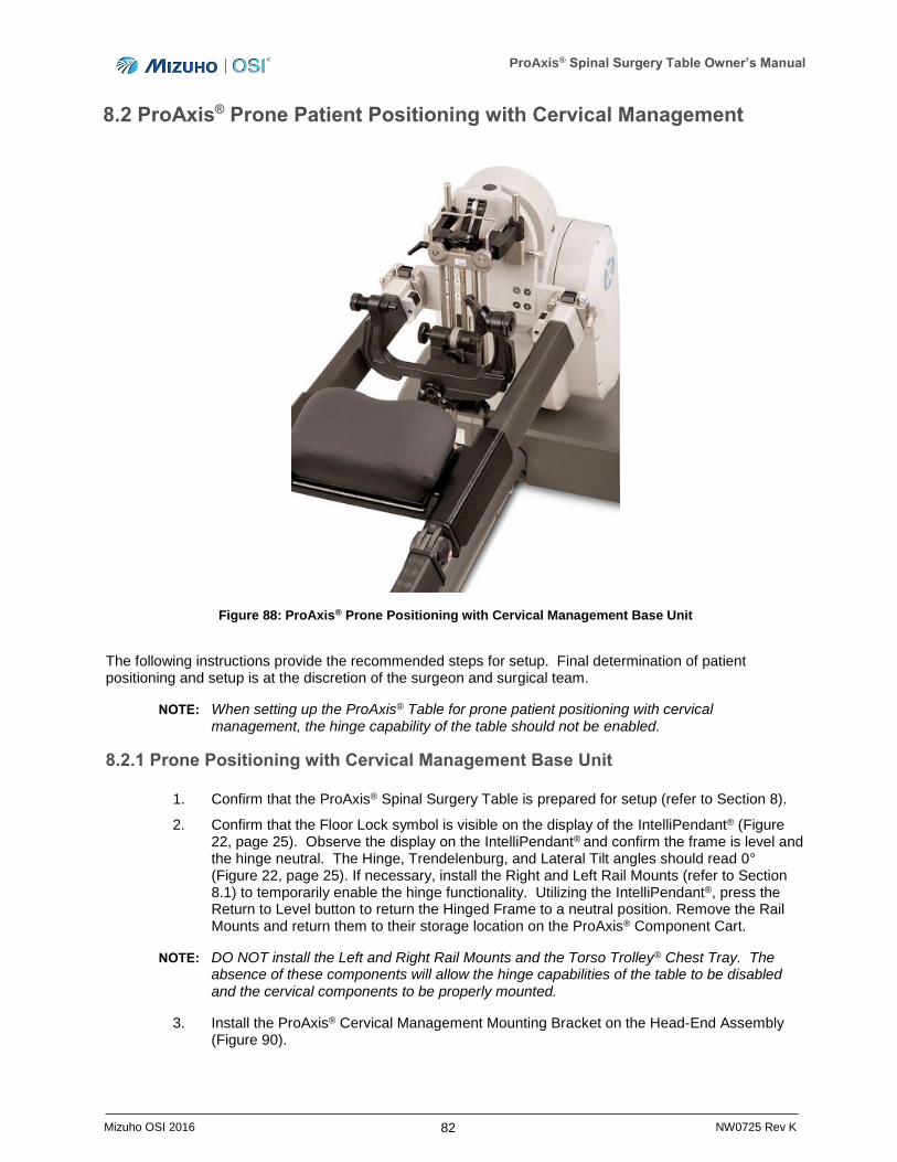
ProAxis® Spinal Surgery Table Owner’s Manual
82 Mizuho OSI 2016 NW0725 Rev K
8.2 ProAxis® Prone Patient Positioning with Cervical Management
Figure 88: ProAxis® Prone Positioning with Cervical Management Base Unit
The following instructions provide the recommended steps for setup. Final determination of patient positioning and setup is at the discretion of the surgeon and surgical team.
NOTE: When setting up the ProAxis® Table for prone patient positioning with cervical management, the hinge capability of the table should not be enabled.
8.2.1 Prone Positioning with Cervical Management Base Unit
1. Confirm that the ProAxis® Spinal Surgery Table is prepared for setup (refer to Section 8).
2. Confirm that the Floor Lock symbol is visible on the display of the IntelliPendant® (Figure 22, page 25). Observe the display on the IntelliPendant® and confirm the frame is level and the hinge neutral. The Hinge, Trendelenburg, and Lateral Tilt angles should read 0° (Figure 22, page 25). If necessary, install the Right and Left Rail Mounts (refer to Section 8.1) to temporarily enable the hinge functionality. Utilizing the IntelliPendant®, press the Return to Level button to return the Hinged Frame to a neutral position. Remove the Rail Mounts and return them to their storage location on the ProAxis® Component Cart.
NOTE: DO NOT install the Left and Right Rail Mounts and the Torso Trolley® Chest Tray. The absence of these components will allow the hinge capabilities of the table to be disabled and the cervical components to be properly mounted.
3. Install the ProAxis® Cervical Management Mounting Bracket on the Head-End Assembly (Figure 90).
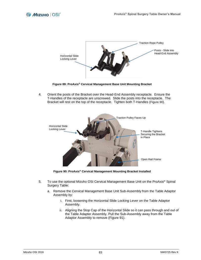
ProAxis® Spinal Surgery Table Owner’s Manual
83 Mizuho OSI 2016 NW0725 Rev K
Figure 89: ProAxis® Cervical Management Base Unit Mounting Bracket
4. Orient the posts of the Bracket over the Head-End Assembly receptacle. Ensure the T-Handles of the receptacle are unscrewed. Slide the posts into the receptacle. The Bracket will rest on the top of the receptacle. Tighten both T-Handles (Figure 90).
Figure 90: ProAxis® Cervical Management Mounting Bracket Installed
5. To use the optional Mizuho OSI Cervical Management Base Unit on the ProAxis® Spinal Surgery Table:
a. Remove the Cervical Management Base Unit Sub-Assembly from the Table Adaptor Assembly by:
i. First, loosening the Horizontal Slide Locking Lever on the Table Adaptor Assembly.
ii. Aligning the Stop Cap of the Horizontal Slide so it can pass through and out of the Table Adapter Assembly. Pull the Sub-Assembly away from the Table Adaptor Assembly to remove (Figure 91).
Posts - Slide into Head-End Assembly
Horizontal Slide Locking Lever
Traction Rope Pulley
T-Handle Tightens Securing the Bracket in Place
Traction Pulley Faces Up
Open Rail Frame
Horizontal Slide Locking Lever
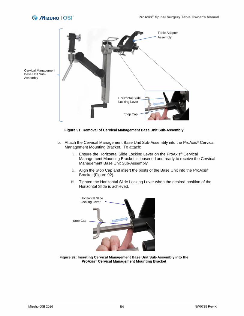
ProAxis® Spinal Surgery Table Owner’s Manual
84 Mizuho OSI 2016 NW0725 Rev K
Figure 91: Removal of Cervical Management Base Unit Sub-Assembly
b. Attach the Cervical Management Base Unit Sub-Assembly into the ProAxis® Cervical Management Mounting Bracket. To attach:
i. Ensure the Horizontal Slide Locking Lever on the ProAxis® Cervical Management Mounting Bracket is loosened and ready to receive the Cervical Management Base Unit Sub-Assembly.
ii. Align the Stop Cap and insert the posts of the Base Unit into the ProAxis® Bracket (Figure 92).
iii. Tighten the Horizontal Slide Locking Lever when the desired position of the Horizontal Slide is achieved.
Figure 92: Inserting Cervical Management Base Unit Sub-Assembly into the ProAxis® Cervical Management Mounting Bracket
Table Adapter
Assembly
Stop Cap
Horizontal Slide Locking Lever
Cervical Management Base Unit Sub-Assembly
Stop Cap
Horizontal Slide Locking Lever
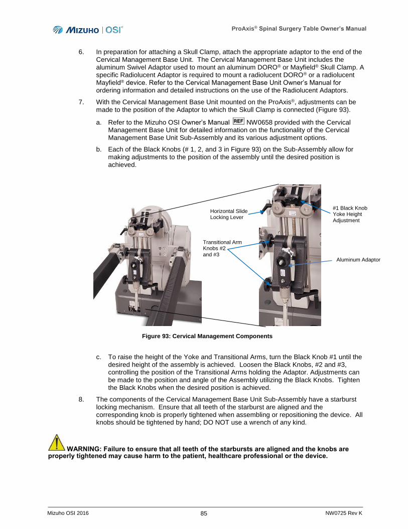
ProAxis® Spinal Surgery Table Owner’s Manual
85 Mizuho OSI 2016 NW0725 Rev K
6. In preparation for attaching a Skull Clamp, attach the appropriate adaptor to the end of the Cervical Management Base Unit. The Cervical Management Base Unit includes the aluminum Swivel Adaptor used to mount an aluminum DORO® or Mayfield® Skull Clamp. A specific Radiolucent Adaptor is required to mount a radiolucent DORO® or a radiolucent Mayfield® device. Refer to the Cervical Management Base Unit Owner’s Manual for ordering information and detailed instructions on the use of the Radiolucent Adaptors.
7. With the Cervical Management Base Unit mounted on the ProAxis®, adjustments can be made to the position of the Adaptor to which the Skull Clamp is connected (Figure 93).
a. Refer to the Mizuho OSI Owner’s Manual NW0658 provided with the Cervical Management Base Unit for detailed information on the functionality of the Cervical Management Base Unit Sub-Assembly and its various adjustment options.
b. Each of the Black Knobs (# 1, 2, and 3 in Figure 93) on the Sub-Assembly allow for making adjustments to the position of the assembly until the desired position is achieved.
Figure 93: Cervical Management Components
c. To raise the height of the Yoke and Transitional Arms, turn the Black Knob #1 until the desired height of the assembly is achieved. Loosen the Black Knobs, #2 and #3, controlling the position of the Transitional Arms holding the Adaptor. Adjustments can be made to the position and angle of the Assembly utilizing the Black Knobs. Tighten the Black Knobs when the desired position is achieved.
8. The components of the Cervical Management Base Unit Sub-Assembly have a starburst locking mechanism. Ensure that all teeth of the starburst are aligned and the corresponding knob is properly tightened when assembling or repositioning the device. All knobs should be tightened by hand; DO NOT use a wrench of any kind.
WARNING: Failure to ensure that all teeth of the starbursts are aligned and the knobs are properly tightened may cause harm to the patient, healthcare professional or the device.
Transitional Arm Knobs #2 and #3
Horizontal Slide Locking Lever
#1 Black Knob Yoke Height Adjustment
Aluminum Adaptor
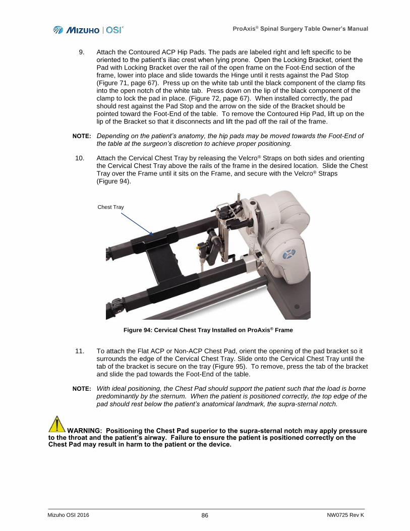
ProAxis® Spinal Surgery Table Owner’s Manual
86 Mizuho OSI 2016 NW0725 Rev K
9. Attach the Contoured ACP Hip Pads. The pads are labeled right and left specific to be oriented to the patient’s iliac crest when lying prone. Open the Locking Bracket, orient the Pad with Locking Bracket over the rail of the open frame on the Foot-End section of the frame, lower into place and slide towards the Hinge until it rests against the Pad Stop (Figure 71, page 67). Press up on the white tab until the black component of the clamp fits into the open notch of the white tab. Press down on the lip of the black component of the clamp to lock the pad in place. (Figure 72, page 67). When installed correctly, the pad should rest against the Pad Stop and the arrow on the side of the Bracket should be pointed toward the Foot-End of the table. To remove the Contoured Hip Pad, lift up on the lip of the Bracket so that it disconnects and lift the pad off the rail of the frame.
NOTE: Depending on the patient’s anatomy, the hip pads may be moved towards the Foot-End of the table at the surgeon’s discretion to achieve proper positioning.
10. Attach the Cervical Chest Tray by releasing the Velcro® Straps on both sides and orienting the Cervical Chest Tray above the rails of the frame in the desired location. Slide the Chest Tray over the Frame until it sits on the Frame, and secure with the Velcro® Straps (Figure 94).
Figure 94: Cervical Chest Tray Installed on ProAxis® Frame
11. To attach the Flat ACP or Non-ACP Chest Pad, orient the opening of the pad bracket so it surrounds the edge of the Cervical Chest Tray. Slide onto the Cervical Chest Tray until the tab of the bracket is secure on the tray (Figure 95). To remove, press the tab of the bracket and slide the pad towards the Foot-End of the table.
NOTE: With ideal positioning, the Chest Pad should support the patient such that the load is borne predominantly by the sternum. When the patient is positioned correctly, the top edge of the pad should rest below the patient’s anatomical landmark, the supra-sternal notch.
WARNING: Positioning the Chest Pad superior to the supra-sternal notch may apply pressure to the throat and the patient’s airway. Failure to ensure the patient is positioned correctly on the Chest Pad may result in harm to the patient or the device.
Chest Tray
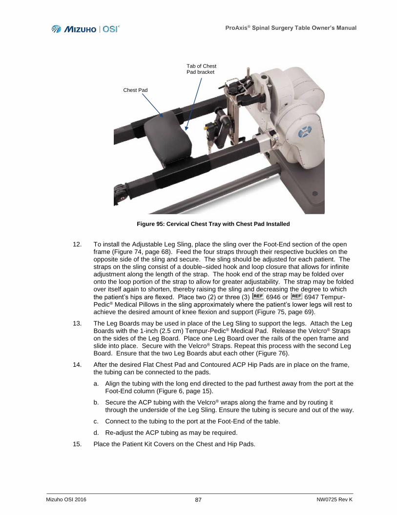
ProAxis® Spinal Surgery Table Owner’s Manual
87 Mizuho OSI 2016 NW0725 Rev K
Figure 95: Cervical Chest Tray with Chest Pad Installed
12. To install the Adjustable Leg Sling, place the sling over the Foot-End section of the open frame (Figure 74, page 68). Feed the four straps through their respective buckles on the opposite side of the sling and secure. The sling should be adjusted for each patient. The straps on the sling consist of a double–sided hook and loop closure that allows for infinite adjustment along the length of the strap. The hook end of the strap may be folded over onto the loop portion of the strap to allow for greater adjustability. The strap may be folded over itself again to shorten, thereby raising the sling and decreasing the degree to which
the patient’s hips are flexed. Place two (2) or three (3) 6946 or 6947 Tempur-Pedic® Medical Pillows in the sling approximately where the patient’s lower legs will rest to achieve the desired amount of knee flexion and support (Figure 75, page 69).
13. The Leg Boards may be used in place of the Leg Sling to support the legs. Attach the Leg Boards with the 1-inch (2.5 cm) Tempur-Pedic® Medical Pad. Release the Velcro® Straps on the sides of the Leg Board. Place one Leg Board over the rails of the open frame and slide into place. Secure with the Velcro® Straps. Repeat this process with the second Leg Board. Ensure that the two Leg Boards abut each other (Figure 76).
14. After the desired Flat Chest Pad and Contoured ACP Hip Pads are in place on the frame, the tubing can be connected to the pads.
a. Align the tubing with the long end directed to the pad furthest away from the port at the Foot-End column (Figure 6, page 15).
b. Secure the ACP tubing with the Velcro® wraps along the frame and by routing it through the underside of the Leg Sling. Ensure the tubing is secure and out of the way.
c. Connect to the tubing to the port at the Foot-End of the table.
d. Re-adjust the ACP tubing as may be required.
15. Place the Patient Kit Covers on the Chest and Hip Pads.
Tab of Chest Pad bracket
Chest Pad
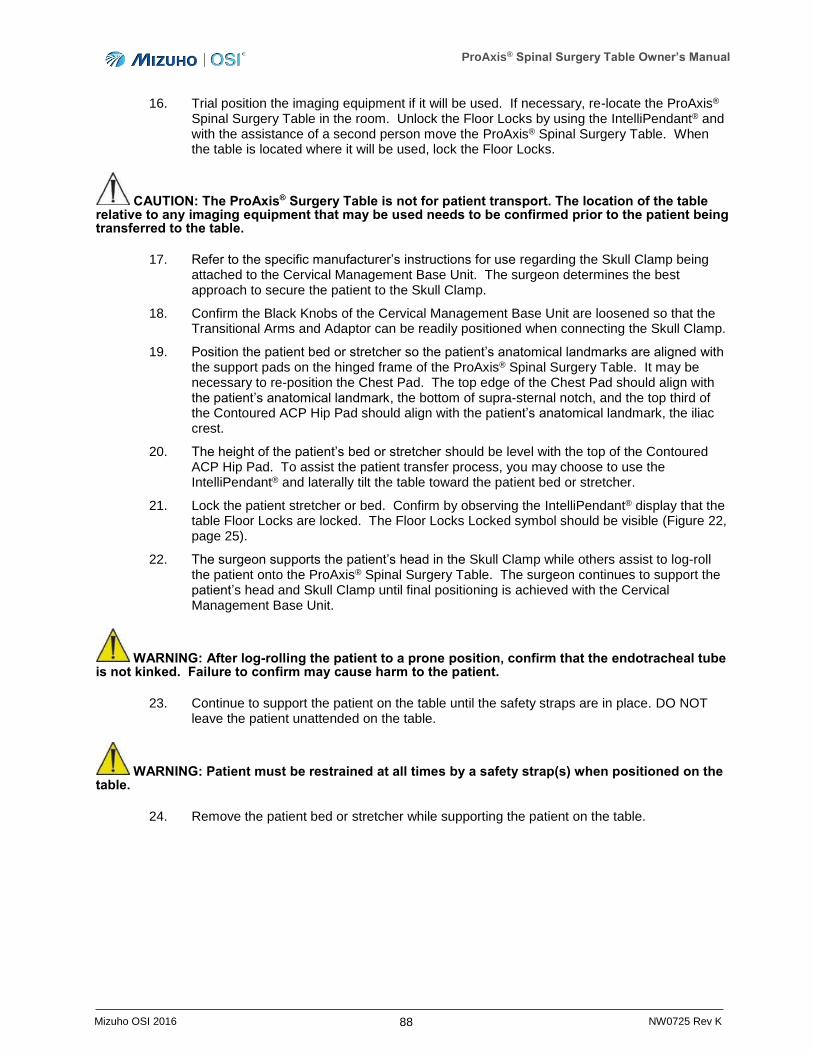
ProAxis® Spinal Surgery Table Owner’s Manual
88 Mizuho OSI 2016 NW0725 Rev K
16. Trial position the imaging equipment if it will be used. If necessary, re-locate the ProAxis® Spinal Surgery Table in the room. Unlock the Floor Locks by using the IntelliPendant® and with the assistance of a second person move the ProAxis® Spinal Surgery Table. When the table is located where it will be used, lock the Floor Locks.
CAUTION: The ProAxis® Surgery Table is not for patient transport. The location of the table relative to any imaging equipment that may be used needs to be confirmed prior to the patient being transferred to the table.
17. Refer to the specific manufacturer’s instructions for use regarding the Skull Clamp being attached to the Cervical Management Base Unit. The surgeon determines the best approach to secure the patient to the Skull Clamp.
18. Confirm the Black Knobs of the Cervical Management Base Unit are loosened so that the Transitional Arms and Adaptor can be readily positioned when connecting the Skull Clamp.
19. Position the patient bed or stretcher so the patient’s anatomical landmarks are aligned with the support pads on the hinged frame of the ProAxis® Spinal Surgery Table. It may be necessary to re-position the Chest Pad. The top edge of the Chest Pad should align with the patient’s anatomical landmark, the bottom of supra-sternal notch, and the top third of the Contoured ACP Hip Pad should align with the patient’s anatomical landmark, the iliac crest.
20. The height of the patient’s bed or stretcher should be level with the top of the Contoured ACP Hip Pad. To assist the patient transfer process, you may choose to use the IntelliPendant® and laterally tilt the table toward the patient bed or stretcher.
21. Lock the patient stretcher or bed. Confirm by observing the IntelliPendant® display that the table Floor Locks are locked. The Floor Locks Locked symbol should be visible (Figure 22, page 25).
22. The surgeon supports the patient’s head in the Skull Clamp while others assist to log-roll the patient onto the ProAxis® Spinal Surgery Table. The surgeon continues to support the patient’s head and Skull Clamp until final positioning is achieved with the Cervical Management Base Unit.
WARNING: After log-rolling the patient to a prone position, confirm that the endotracheal tube is not kinked. Failure to confirm may cause harm to the patient.
23. Continue to support the patient on the table until the safety straps are in place. DO NOT leave the patient unattended on the table.
WARNING: Patient must be restrained at all times by a safety strap(s) when positioned on the table.
24. Remove the patient bed or stretcher while supporting the patient on the table.
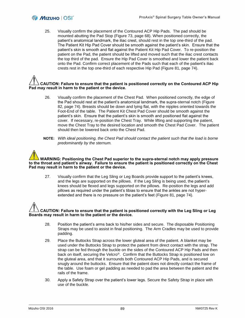
ProAxis® Spinal Surgery Table Owner’s Manual
89 Mizuho OSI 2016 NW0725 Rev K
25. Visually confirm the placement of the Contoured ACP Hip Pads. The pad should be mounted abutting the Pad Stop (Figure 73, page 68). When positioned correctly, the patient’s anatomical landmark, the iliac crest, should rest in the top one-third of the pad. The Patient Kit Hip Pad Cover should be smooth against the patient’s skin. Ensure that the patient’s skin is smooth and flat against the Patient Kit Hip Pad Cover. To re-position the patient on the Pad, the patient should be lifted and moved such that the iliac crest contacts the top third of the pad. Ensure the Hip Pad Cover is smoothed and lower the patient back onto the Pad. Confirm correct placement of the Pads such that each of the patient’s iliac crests rest in the top one-third of each respective Hip Pad (Figure 81, page 74).
CAUTION: Failure to ensure that the patient is positioned correctly on the Contoured ACP Hip Pad may result in harm to the patient or the device.
26. Visually confirm the placement of the Chest Pad. When positioned correctly, the edge of the Pad should rest at the patient’s anatomical landmark, the supra-sternal notch (Figure 82, page 74). Breasts should be down and lying flat, with the nipples oriented towards the Foot-End of the table. The Patient Kit Chest Pad Cover should be smooth against the patient’s skin. Ensure that the patient’s skin is smooth and positioned flat against the cover. If necessary, re-position the Chest Tray. While lifting and supporting the patient, move the Chest Tray to the desired location and smooth the Chest Pad Cover. The patient should then be lowered back onto the Chest Pad.
NOTE: With ideal positioning, the Chest Pad should contact the patient such that the load is borne predominantly by the sternum.
WARNING: Positioning the Chest Pad superior to the supra-sternal notch may apply pressure to the throat and patient’s airway. Failure to ensure the patient is positioned correctly on the Chest Pad may result in harm to the patient or the device.
27. Visually confirm that the Leg Sling or Leg Boards provide support to the patient’s knees, and the legs are supported on the pillows. If the Leg Sling is being used, the patient’s knees should be flexed and legs supported on the pillows. Re-position the legs and add pillows as required under the patient’s tibias to ensure that the ankles are not hyper-extended and there is no pressure on the patient’s feet (Figure 81, page 74).
CAUTION: Failure to ensure that the patient is positioned correctly with the Leg Sling or Leg Boards may result in harm to the patient or the device.
28. Position the patient’s arms back to his/her sides and secure. The disposable Positioning Straps may be used to assist in final positioning. The Arm Cradles may be used to provide padding.
29. Place the Buttocks Strap across the lower gluteal area of the patient. A blanket may be used under the Buttocks Strap to protect the patient from direct contact with the strap. The strap can be fed through the buckle on the sides of the Contoured ACP Hip Pads and then back on itself, securing the Velcro®. Confirm that the Buttocks Strap is positioned low on the gluteal area, and that it surrounds both Contoured ACP Hip Pads, and is secured snugly around the buttocks. Ensure that the patient does not directly contact the frame of the table. Use foam or gel padding as needed to pad the area between the patient and the rails of the frame.
30. Apply a Safety Strap over the patient’s lower legs. Secure the Safety Strap in place with use of the buckle.
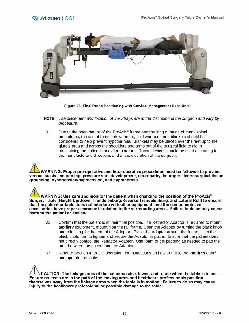
ProAxis® Spinal Surgery Table Owner’s Manual
90 Mizuho OSI 2016 NW0725 Rev K
Figure 96: Final Prone Positioning with Cervical Management Base Unit
NOTE: The placement and location of the Straps are at the discretion of the surgeon and vary by procedure.
31. Due to the open nature of the ProAxis® frame and the long duration of many spinal procedures, the use of forced air warmers, fluid warmers, and blankets should be considered to help prevent hypothermia. Blankets may be placed over the feet up to the gluteal area and across the shoulders and arms out of the surgical field to aid in maintaining the patient’s body temperature. These devices should be used according to the manufacturer’s directions and at the discretion of the surgeon.
WARNING: Proper pre-operative and intra-operative procedures must be followed to prevent venous stasis and pooling, pressure sore development, neuropathy, improper electrosurgical tissue grounding, hypertension/hypotension, and hypothermia.
WARNING: Use care and monitor the patient when changing the position of the ProAxis® Surgery Table (Height Up/Down, Trendelenburg/Reverse Trendelenburg, and Lateral Roll) to ensure that the patient or table does not interfere with other equipment, and the components and accessories have proper clearance in relation to the surrounding areas. Failure to do so may cause harm to the patient or device.
32. Confirm that the patient is in their final position. If a Retractor Adaptor is required to mount auxiliary equipment, mount it on the rail frame. Open the Adaptor by turning the black knob and releasing the bottom of the Adaptor. Place the Adaptor around the frame, align the black knob, turn to tighten and secure the Adaptor in place. Ensure that the patient does not directly contact the Retractor Adaptor. Use foam or gel padding as needed to pad the area between the patient and the Adaptor.
33. Refer to Section 4, Basic Operation, for instructions on how to utilize the IntelliPendant® and operate the table.
CAUTION: The linkage arms of the columns raise, lower, and rotate when the table is in use. Ensure no items are in the path of the moving arms and healthcare professionals position themselves away from the linkage arms when the table is in motion. Failure to do so may cause injury to the healthcare professional or possible damage to the table.
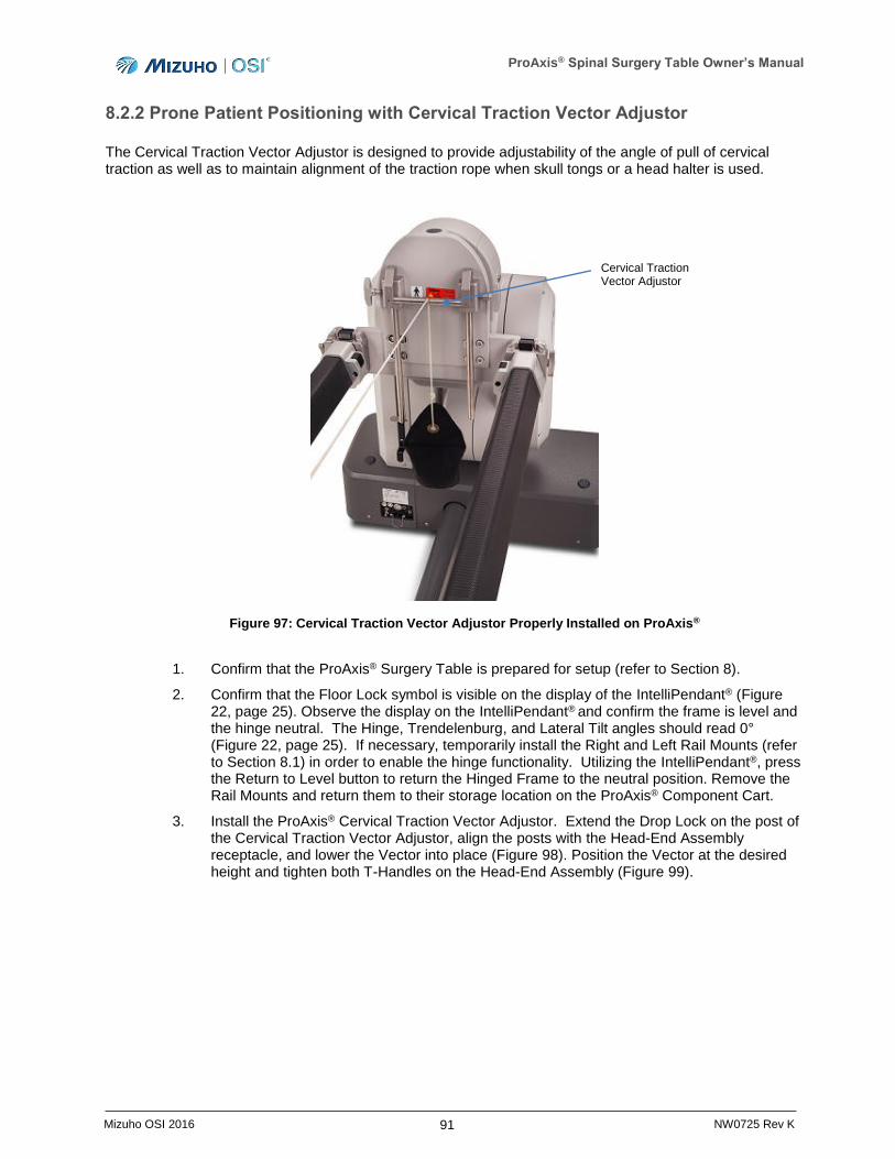
ProAxis® Spinal Surgery Table Owner’s Manual
91 Mizuho OSI 2016 NW0725 Rev K
8.2.2 Prone Patient Positioning with Cervical Traction Vector Adjustor
The Cervical Traction Vector Adjustor is designed to provide adjustability of the angle of pull of cervical traction as well as to maintain alignment of the traction rope when skull tongs or a head halter is used.
Figure 97: Cervical Traction Vector Adjustor Properly Installed on ProAxis®
1. Confirm that the ProAxis® Surgery Table is prepared for setup (refer to Section 8).
2. Confirm that the Floor Lock symbol is visible on the display of the IntelliPendant® (Figure 22, page 25). Observe the display on the IntelliPendant® and confirm the frame is level and the hinge neutral. The Hinge, Trendelenburg, and Lateral Tilt angles should read 0° (Figure 22, page 25). If necessary, temporarily install the Right and Left Rail Mounts (refer to Section 8.1) in order to enable the hinge functionality. Utilizing the IntelliPendant®, press the Return to Level button to return the Hinged Frame to the neutral position. Remove the Rail Mounts and return them to their storage location on the ProAxis® Component Cart.
3. Install the ProAxis® Cervical Traction Vector Adjustor. Extend the Drop Lock on the post of the Cervical Traction Vector Adjustor, align the posts with the Head-End Assembly receptacle, and lower the Vector into place (Figure 98). Position the Vector at the desired height and tighten both T-Handles on the Head-End Assembly (Figure 99).
Cervical Traction Vector Adjustor
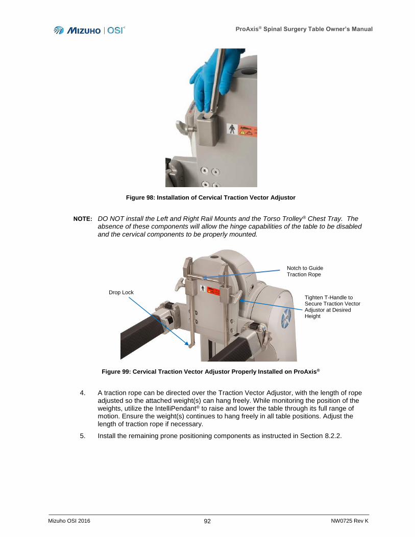
ProAxis® Spinal Surgery Table Owner’s Manual
92 Mizuho OSI 2016 NW0725 Rev K
Figure 98: Installation of Cervical Traction Vector Adjustor
NOTE: DO NOT install the Left and Right Rail Mounts and the Torso Trolley® Chest Tray. The absence of these components will allow the hinge capabilities of the table to be disabled and the cervical components to be properly mounted.
Figure 99: Cervical Traction Vector Adjustor Properly Installed on ProAxis®
4. A traction rope can be directed over the Traction Vector Adjustor, with the length of rope adjusted so the attached weight(s) can hang freely. While monitoring the position of the weights, utilize the IntelliPendant® to raise and lower the table through its full range of motion. Ensure the weight(s) continues to hang freely in all table positions. Adjust the length of traction rope if necessary.
5. Install the remaining prone positioning components as instructed in Section 8.2.2.
Notch to Guide Traction Rope
Drop Lock Tighten T-Handle to Secure Traction Vector Adjustor at Desired Height
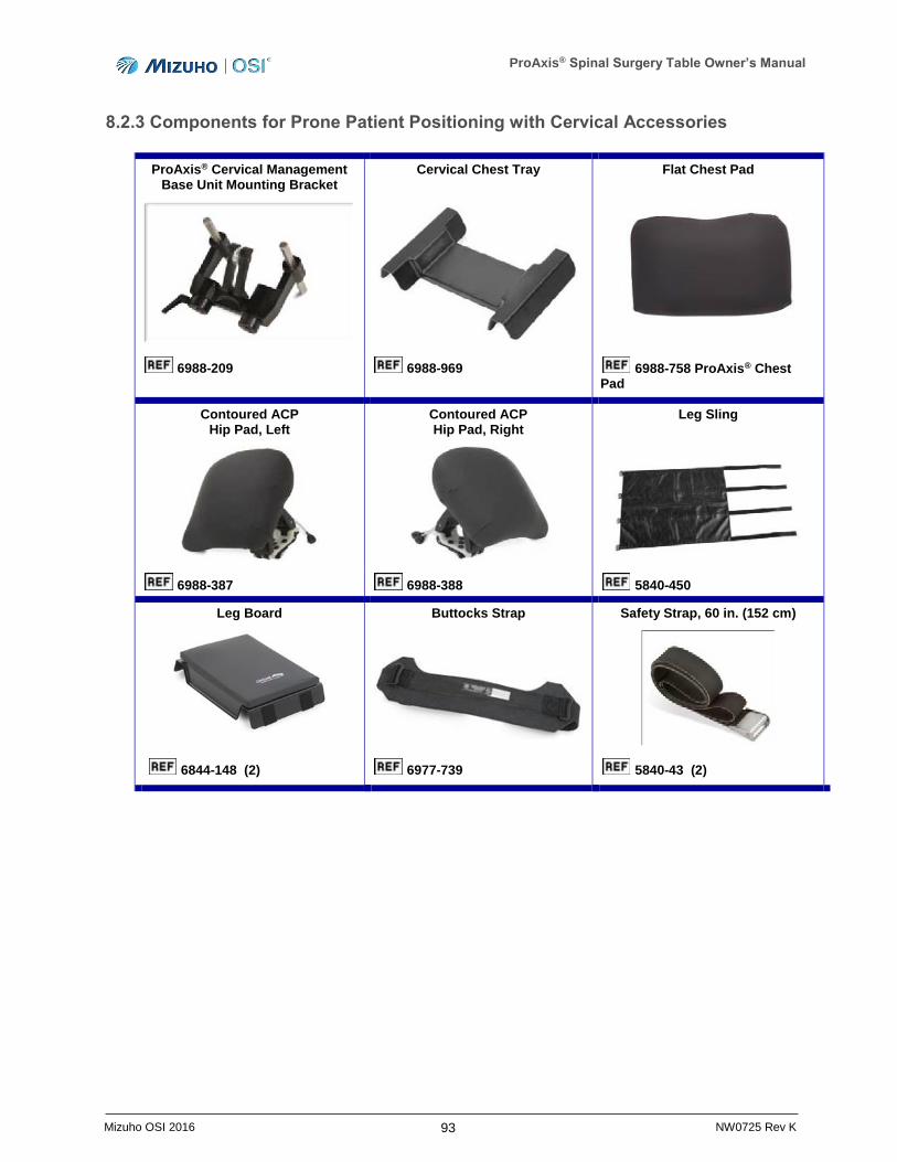
ProAxis® Spinal Surgery Table Owner’s Manual
93 Mizuho OSI 2016 NW0725 Rev K
8.2.3 Components for Prone Patient Positioning with Cervical Accessories
ProAxis® Cervical Management Base Unit Mounting Bracket
Cervical Chest Tray
Flat Chest Pad
6988-209
6988-969
6988-758 ProAxis® Chest Pad
Contoured ACP Hip Pad, Left
Contoured ACP Hip Pad, Right
Leg Sling
6988-387 6988-388 5840-450
Leg Board
Buttocks Strap
Safety Strap, 60 in. (152 cm)
6844-148 (2) 6977-739 5840-43 (2)
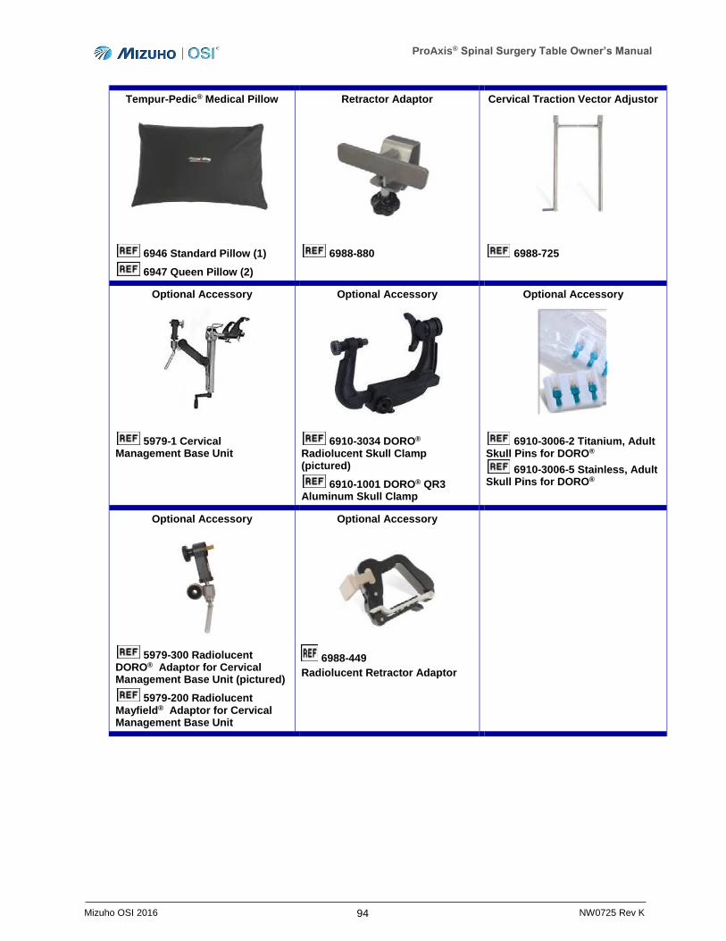
ProAxis® Spinal Surgery Table Owner’s Manual
94 Mizuho OSI 2016 NW0725 Rev K
Tempur-Pedic® Medical Pillow
Retractor Adaptor
Cervical Traction Vector Adjustor
6946 Standard Pillow (1)
6947 Queen Pillow (2)
6988-880
6988-725
Optional Accessory
Optional Accessory
Optional Accessory
5979-1 Cervical Management Base Unit
6910-3034 DORO® Radiolucent Skull Clamp (pictured)
6910-1001 DORO® QR3 Aluminum Skull Clamp
6910-3006-2 Titanium, Adult Skull Pins for DORO®
6910-3006-5 Stainless, Adult Skull Pins for DORO®
Optional Accessory
Optional Accessory
5979-300 Radiolucent DORO® Adaptor for Cervical Management Base Unit (pictured)
5979-200 Radiolucent Mayfield® Adaptor for Cervical Management Base Unit
6988-449
Radiolucent Retractor Adaptor
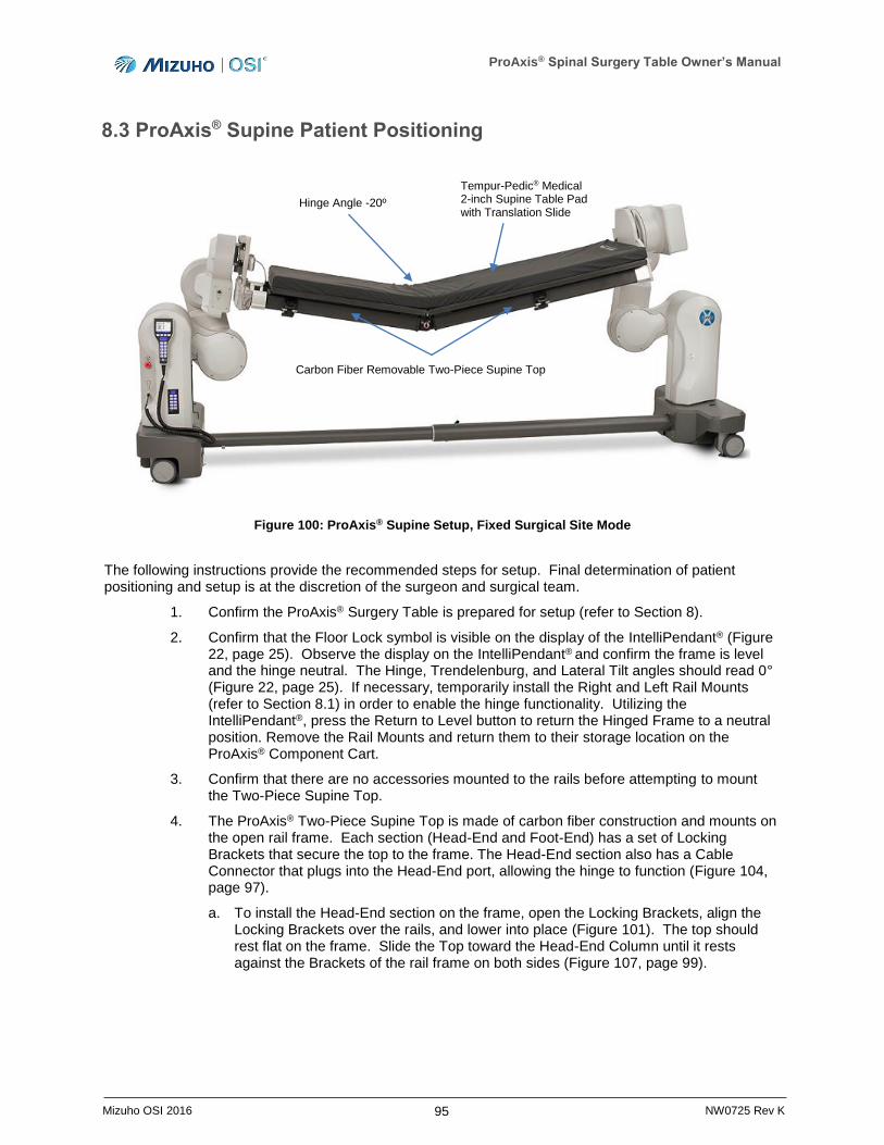
ProAxis® Spinal Surgery Table Owner’s Manual
95 Mizuho OSI 2016 NW0725 Rev K
8.3 ProAxis® Supine Patient Positioning
Figure 100: ProAxis® Supine Setup, Fixed Surgical Site Mode
The following instructions provide the recommended steps for setup. Final determination of patient positioning and setup is at the discretion of the surgeon and surgical team.
1. Confirm the ProAxis® Surgery Table is prepared for setup (refer to Section 8).
2. Confirm that the Floor Lock symbol is visible on the display of the IntelliPendant® (Figure 22, page 25). Observe the display on the IntelliPendant® and confirm the frame is level and the hinge neutral. The Hinge, Trendelenburg, and Lateral Tilt angles should read 0° (Figure 22, page 25). If necessary, temporarily install the Right and Left Rail Mounts (refer to Section 8.1) in order to enable the hinge functionality. Utilizing the IntelliPendant®, press the Return to Level button to return the Hinged Frame to a neutral position. Remove the Rail Mounts and return them to their storage location on the ProAxis® Component Cart.
3. Confirm that there are no accessories mounted to the rails before attempting to mount the Two-Piece Supine Top.
4. The ProAxis® Two-Piece Supine Top is made of carbon fiber construction and mounts on the open rail frame. Each section (Head-End and Foot-End) has a set of Locking Brackets that secure the top to the frame. The Head-End section also has a Cable Connector that plugs into the Head-End port, allowing the hinge to function (Figure 104, page 97).
a. To install the Head-End section on the frame, open the Locking Brackets, align the Locking Brackets over the rails, and lower into place (Figure 101). The top should rest flat on the frame. Slide the Top toward the Head-End Column until it rests against the Brackets of the rail frame on both sides (Figure 107, page 99).
Hinge Angle -20º
Tempur-Pedic® Medical 2-inch Supine Table Pad with Translation Slide
Carbon Fiber Removable Two-Piece Supine Top
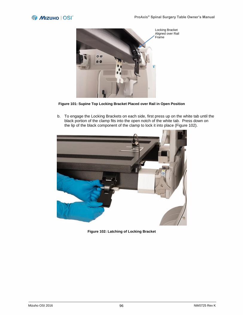
ProAxis® Spinal Surgery Table Owner’s Manual
96 Mizuho OSI 2016 NW0725 Rev K
Figure 101: Supine Top Locking Bracket Placed over Rail in Open Position
b. To engage the Locking Brackets on each side, first press up on the white tab until the black portion of the clamp fits into the open notch of the white tab. Press down on the lip of the black component of the clamp to lock it into place (Figure 102).
Figure 102: Latching of Locking Bracket
Locking Bracket Aligned over Rail Frame
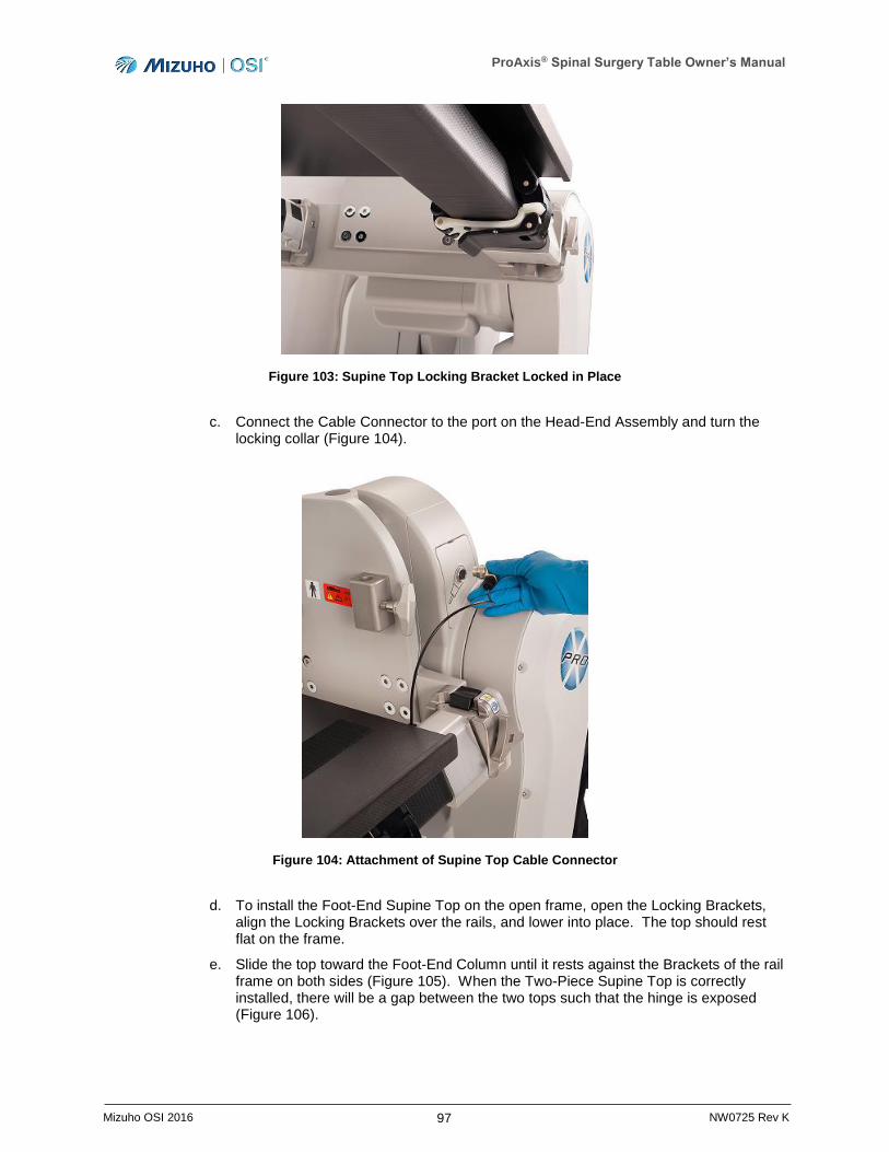
ProAxis® Spinal Surgery Table Owner’s Manual
97 Mizuho OSI 2016 NW0725 Rev K
Figure 103: Supine Top Locking Bracket Locked in Place
c. Connect the Cable Connector to the port on the Head-End Assembly and turn the locking collar (Figure 104).
Figure 104: Attachment of Supine Top Cable Connector
d. To install the Foot-End Supine Top on the open frame, open the Locking Brackets, align the Locking Brackets over the rails, and lower into place. The top should rest flat on the frame.
e. Slide the top toward the Foot-End Column until it rests against the Brackets of the rail frame on both sides (Figure 105). When the Two-Piece Supine Top is correctly installed, there will be a gap between the two tops such that the hinge is exposed (Figure 106).
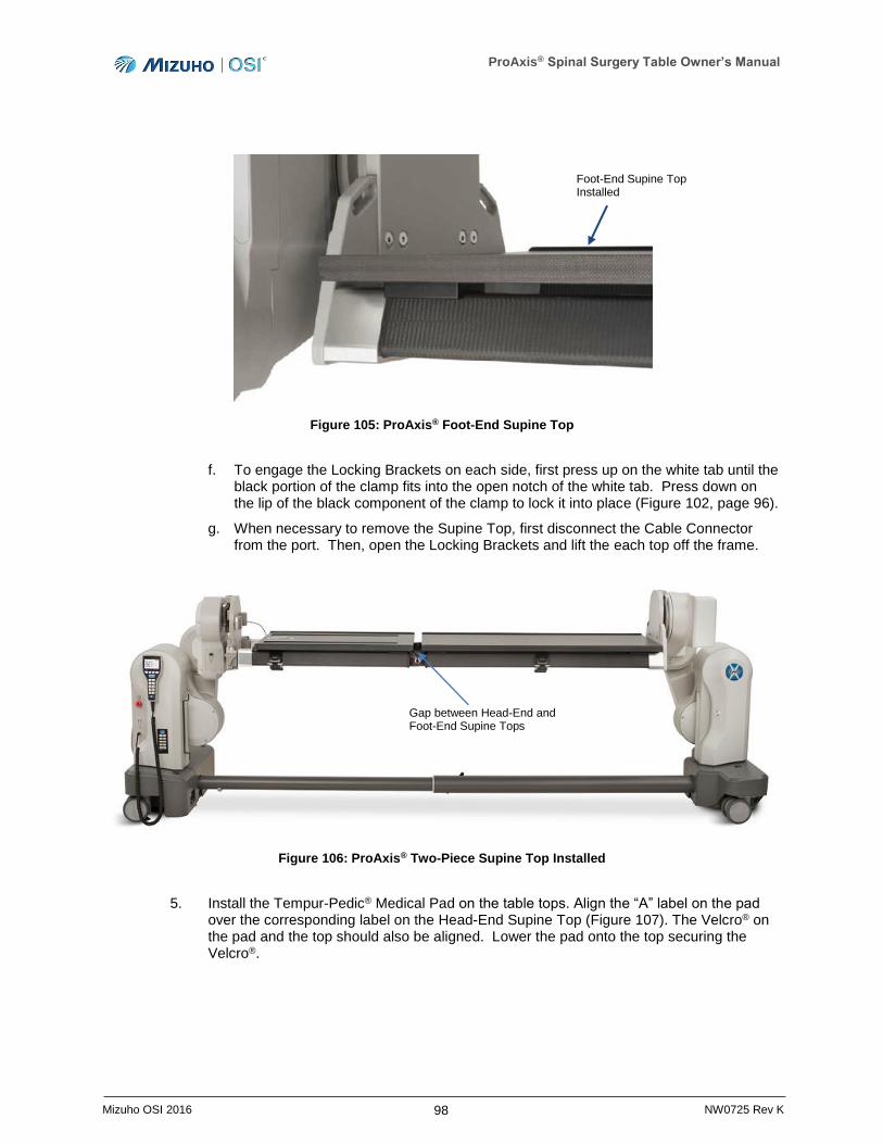
ProAxis® Spinal Surgery Table Owner’s Manual
98 Mizuho OSI 2016 NW0725 Rev K
Figure 105: ProAxis® Foot-End Supine Top
f. To engage the Locking Brackets on each side, first press up on the white tab until the black portion of the clamp fits into the open notch of the white tab. Press down on the lip of the black component of the clamp to lock it into place (Figure 102, page 96).
g. When necessary to remove the Supine Top, first disconnect the Cable Connector from the port. Then, open the Locking Brackets and lift the each top off the frame.
Figure 106: ProAxis® Two-Piece Supine Top Installed
5. Install the Tempur-Pedic® Medical Pad on the table tops. Align the “A” label on the pad over the corresponding label on the Head-End Supine Top (Figure 107). The Velcro® on the pad and the top should also be aligned. Lower the pad onto the top securing the Velcro®.
Foot-End Supine Top Installed
Gap between Head-End and Foot-End Supine Tops
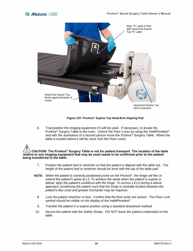
ProAxis® Spinal Surgery Table Owner’s Manual
99 Mizuho OSI 2016 NW0725 Rev K
Figure 107: ProAxis® Supine Top Head-End Aligning Pad
6. Trial position the imaging equipment if it will be used. If necessary, re-locate the ProAxis® Surgery Table in the room. Unlock the Floor Locks by using the IntelliPendant® and with the assistance of a second person move the ProAxis® Surgery Table. When the table is located where it will be used, lock the Floor Locks.
CAUTION: The ProAxis® Surgery Table is not for patient transport. The location of the table relative to any imaging equipment that may be used needs to be confirmed prior to the patient being transferred to the table.
7. Position the patient bed or stretcher so that the patient is aligned with the table top. The height of the patient bed or stretcher should be level with the top of the table pad.
NOTE: When the patient is correctly positioned prone on the ProAxis®, the hinge will flex or extend the patient’s spine at L3. To achieve the same when the patient is supine or lateral, align the patient’s umbilicus with the hinge. To access L4-L5 during a lateral approach, positioning the patient such that the hinge is centrally located between the patient’s iliac crest and greater trochanter may be required.
8. Lock the patient stretcher or bed. Confirm that the floor locks are locked. The Floor Lock symbol should be visible on the display of the IntelliPendant®.
9. Transfer the patient in a supine position using a standard drawsheet method.
10. Secure the patient with the Safety Straps. DO NOT leave the patient unattended on the table.
Head-End Supine Top Wire Connector
Head-End Supine Top Rests against Bracket of Frame
Align “A” Label of Pad with Head-End Supine Top “A” Label
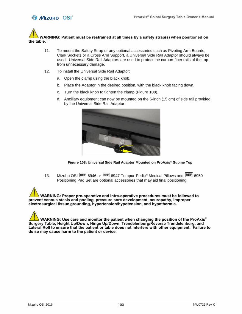
ProAxis® Spinal Surgery Table Owner’s Manual
100 Mizuho OSI 2016 NW0725 Rev K
WARNING: Patient must be restrained at all times by a safety strap(s) when positioned on the table.
11. To mount the Safety Strap or any optional accessories such as Pivoting Arm Boards, Clark Sockets or a Cross Arm Support, a Universal Side Rail Adaptor should always be used. Universal Side Rail Adaptors are used to protect the carbon-fiber rails of the top from unnecessary damage.
12. To install the Universal Side Rail Adaptor:
a. Open the clamp using the black knob.
b. Place the Adaptor in the desired position, with the black knob facing down.
c. Turn the black knob to tighten the clamp (Figure 108).
d. Ancillary equipment can now be mounted on the 6-inch (15 cm) of side rail provided by the Universal Side Rail Adaptor.
Figure 108: Universal Side Rail Adaptor Mounted on ProAxis® Supine Top
13. Mizuho OSI 6946 or 6947 Tempur-Pedic® Medical Pillows and 6950 Positioning Pad Set are optional accessories that may aid final positioning.
WARNING: Proper pre-operative and intra-operative procedures must be followed to prevent venous stasis and pooling, pressure sore development, neuropathy, improper electrosurgical tissue grounding, hypertension/hypotension, and hypothermia.
WARNING: Use care and monitor the patient when changing the position of the ProAxis®
Surgery Table; Height Up/Down, Hinge Up/Down, Trendelenburg/Reverse Trendelenburg, and Lateral Roll to ensure that the patient or table does not interfere with other equipment. Failure to do so may cause harm to the patient or device.
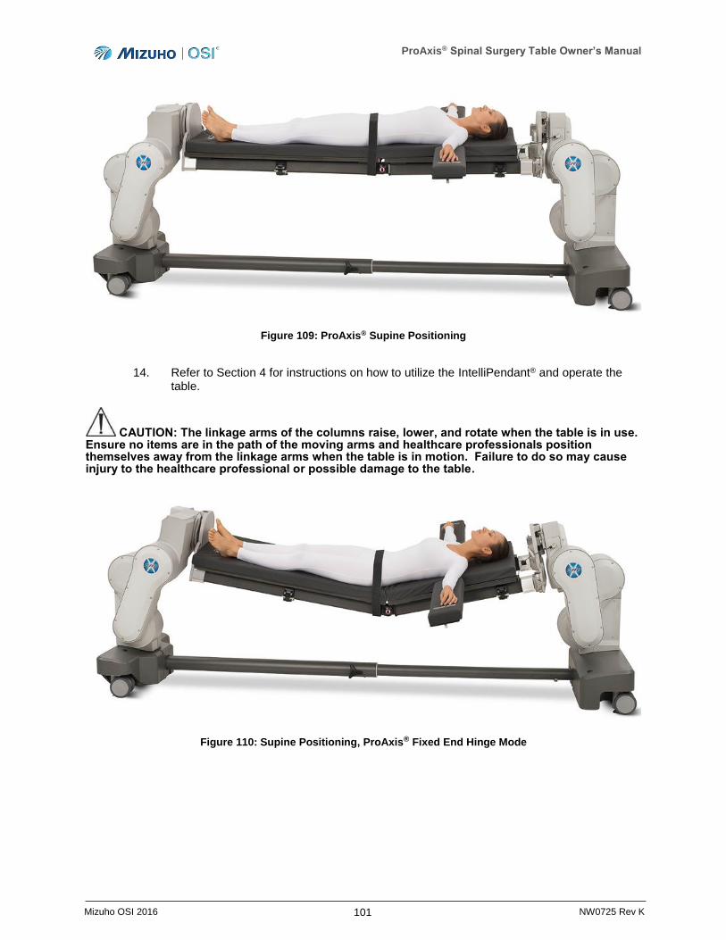
ProAxis® Spinal Surgery Table Owner’s Manual
101 Mizuho OSI 2016 NW0725 Rev K
Figure 109: ProAxis® Supine Positioning
14. Refer to Section 4 for instructions on how to utilize the IntelliPendant® and operate the table.
CAUTION: The linkage arms of the columns raise, lower, and rotate when the table is in use. Ensure no items are in the path of the moving arms and healthcare professionals position themselves away from the linkage arms when the table is in motion. Failure to do so may cause injury to the healthcare professional or possible damage to the table.
Figure 110: Supine Positioning, ProAxis® Fixed End Hinge Mode
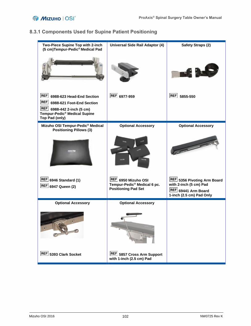
ProAxis® Spinal Surgery Table Owner’s Manual
102 Mizuho OSI 2016 NW0725 Rev K
8.3.1 Components Used for Supine Patient Positioning
Two-Piece Supine Top with 2-inch (5 cm)Tempur-Pedic® Medical Pad
Universal Side Rail Adaptor (4)
Safety Straps (2)
6988-623 Head-End Section
6988-621 Foot-End Section
6988-442 2-inch (5 cm) Tempur-Pedic® Medical Supine Top Pad (only)
6977-959 5855-550
Mizuho OSI Tempur-Pedic® Medical Positioning Pillows (3)
Optional Accessory
Optional Accessory
6946 Standard (1)
6947 Queen (2)
6950 Mizuho OSI Tempur-Pedic® Medical 6 pc. Positioning Pad Set
5356 Pivoting Arm Board with 2-inch (5 cm) Pad
69441 Arm Board 1-inch (2.5 cm) Pad Only
Optional Accessory
Optional Accessory
5393 Clark Socket
5857 Cross Arm Support with 1-inch (2.5 cm) Pad
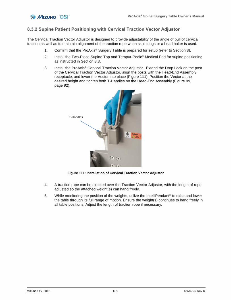
ProAxis® Spinal Surgery Table Owner’s Manual
103 Mizuho OSI 2016 NW0725 Rev K
8.3.2 Supine Patient Positioning with Cervical Traction Vector Adjustor
The Cervical Traction Vector Adjustor is designed to provide adjustability of the angle of pull of cervical traction as well as to maintain alignment of the traction rope when skull tongs or a head halter is used.
1. Confirm that the ProAxis® Surgery Table is prepared for setup (refer to Section 8).
2. Install the Two-Piece Supine Top and Tempur-Pedic® Medical Pad for supine positioning as instructed in Section 8.3.
3. Install the ProAxis® Cervical Traction Vector Adjustor. Extend the Drop Lock on the post of the Cervical Traction Vector Adjustor, align the posts with the Head-End Assembly receptacle, and lower the Vector into place (Figure 111). Position the Vector at the desired height and tighten both T-Handles on the Head-End Assembly (Figure 99, page 92).
Figure 111: Installation of Cervical Traction Vector Adjustor
4. A traction rope can be directed over the Traction Vector Adjustor, with the length of rope adjusted so the attached weight(s) can hang freely.
5. While monitoring the position of the weights, utilize the IntelliPendant® to raise and lower the table through its full range of motion. Ensure the weight(s) continues to hang freely in all table positions. Adjust the length of traction rope if necessary.
T-Handles
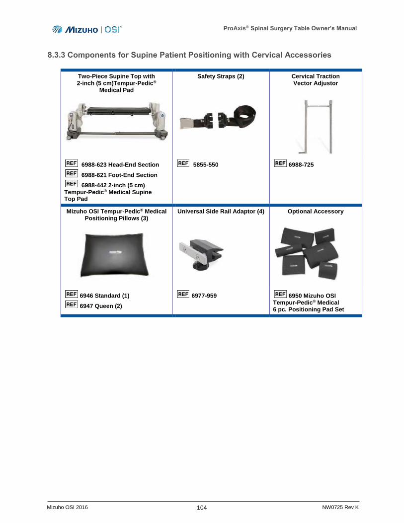
ProAxis® Spinal Surgery Table Owner’s Manual
104 Mizuho OSI 2016 NW0725 Rev K
8.3.3 Components for Supine Patient Positioning with Cervical Accessories
Two-Piece Supine Top with 2-inch (5 cm)Tempur-Pedic®
Medical Pad
Safety Straps (2)
Cervical Traction Vector Adjustor
6988-623 Head-End Section
6988-621 Foot-End Section
6988-442 2-inch (5 cm) Tempur-Pedic® Medical Supine Top Pad
5855-550 6988-725
Mizuho OSI Tempur-Pedic® Medical Positioning Pillows (3)
Universal Side Rail Adaptor (4)
Optional Accessory
6946 Standard (1)
6947 Queen (2)
6977-959 6950 Mizuho OSI Tempur-Pedic® Medical 6 pc. Positioning Pad Set
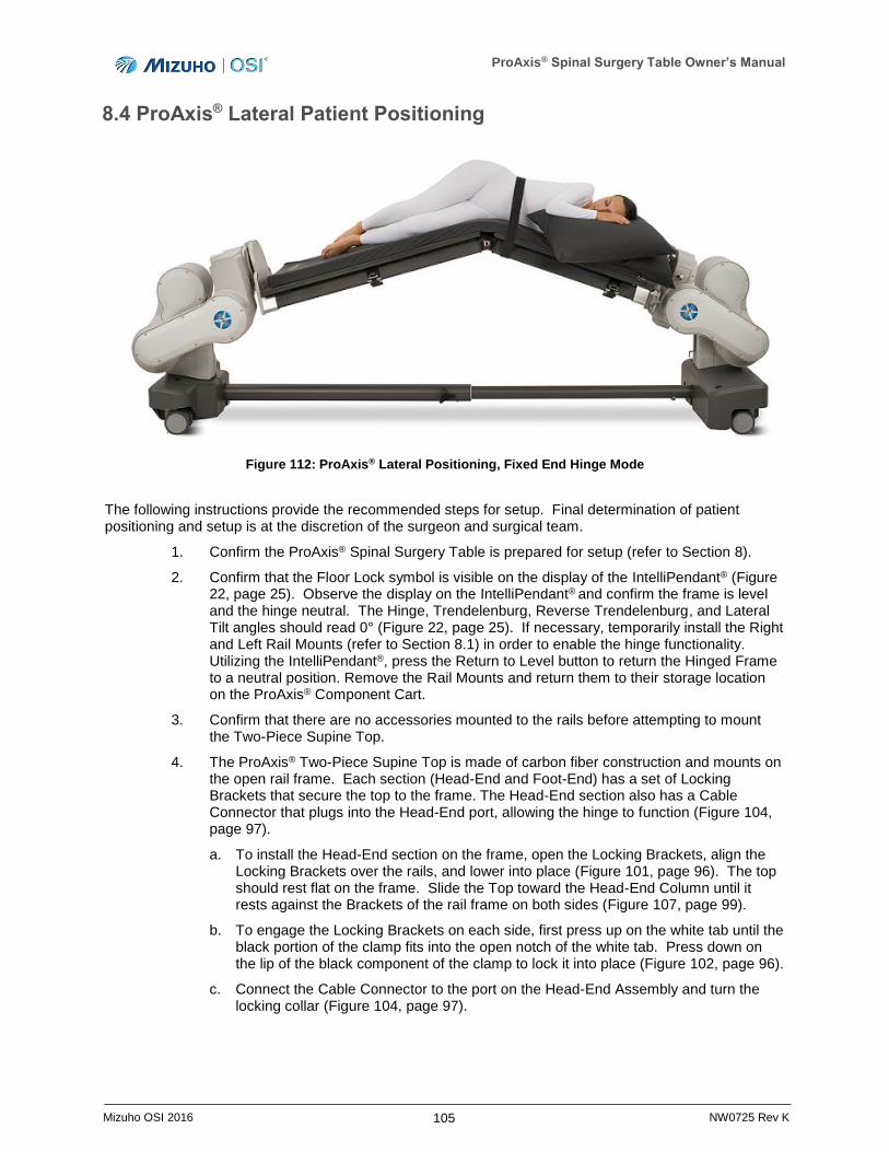
ProAxis® Spinal Surgery Table Owner’s Manual
105 Mizuho OSI 2016 NW0725 Rev K
8.4 ProAxis® Lateral Patient Positioning
Figure 112: ProAxis® Lateral Positioning, Fixed End Hinge Mode
The following instructions provide the recommended steps for setup. Final determination of patient positioning and setup is at the discretion of the surgeon and surgical team.
1. Confirm the ProAxis® Spinal Surgery Table is prepared for setup (refer to Section 8).
2. Confirm that the Floor Lock symbol is visible on the display of the IntelliPendant® (Figure 22, page 25). Observe the display on the IntelliPendant® and confirm the frame is level and the hinge neutral. The Hinge, Trendelenburg, Reverse Trendelenburg, and Lateral Tilt angles should read 0° (Figure 22, page 25). If necessary, temporarily install the Right and Left Rail Mounts (refer to Section 8.1) in order to enable the hinge functionality. Utilizing the IntelliPendant®, press the Return to Level button to return the Hinged Frame to a neutral position. Remove the Rail Mounts and return them to their storage location on the ProAxis® Component Cart.
3. Confirm that there are no accessories mounted to the rails before attempting to mount the Two-Piece Supine Top.
4. The ProAxis® Two-Piece Supine Top is made of carbon fiber construction and mounts on the open rail frame. Each section (Head-End and Foot-End) has a set of Locking Brackets that secure the top to the frame. The Head-End section also has a Cable Connector that plugs into the Head-End port, allowing the hinge to function (Figure 104, page 97).
a. To install the Head-End section on the frame, open the Locking Brackets, align the Locking Brackets over the rails, and lower into place (Figure 101, page 96). The top should rest flat on the frame. Slide the Top toward the Head-End Column until it rests against the Brackets of the rail frame on both sides (Figure 107, page 99).
b. To engage the Locking Brackets on each side, first press up on the white tab until the black portion of the clamp fits into the open notch of the white tab. Press down on the lip of the black component of the clamp to lock it into place (Figure 102, page 96).
c. Connect the Cable Connector to the port on the Head-End Assembly and turn the locking collar (Figure 104, page 97).
ProAxis® Spinal Surgery Table Owner’s Manual
106 Mizuho OSI 2016 NW0725 Rev K
d. To install the Foot-End Supine Top on the open frame, open the Locking Brackets, align the Locking Brackets over the rails, and lower into place. The top should rest flat on the frame.
e. Slide the top toward the Foot-End Column until it rests against the Brackets of the rail frame on both sides. (Figure 105, page 98). When the Two-Piece Supine Top is correctly installed, there will be a gap between the two tops such that the hinge is exposed (Figure 106, page 98).
f. To engage the Locking Brackets on each side, first press up on the white tab until the black portion of the clamp fits into the open notch of the white tab. Press down on the lip of the black component of the clamp to lock it into place (Figure 102, page 96).
g. When necessary to remove the Supine Top, first disconnect the Cable Connector from the port. Then, open the Locking Brackets and lift the each top off the frame.
5. Install the Tempur-Pedic® Medical Pad on the table tops. Align the “A” label on the pad over the corresponding label on the Head-End Supine Top (Figure 107, page 99). The Velcro® on the pad and the top should also be aligned. Lower the pad onto the top securing the Velcro®.
6. Trial position the imaging equipment if it will be used. If necessary, re-locate the ProAxis® Surgery Table in the room. Unlock the Floor Locks by using the IntelliPendant® and with the assistance of a second person move the ProAxis® Surgery Table. When the table is located where it will be used, lock the Floor Locks.
CAUTION: The ProAxis® Surgery Table is not for patient transport. The location of the table relative to any imaging equipment that may be used needs to be confirmed prior to the patient being transferred to the table.
7. Position the patient bed or stretcher so that the patient is aligned with the table top. The height of the patient bed or stretcher should be level with the top of the table pad.
NOTE: When the patient is correctly positioned prone on the ProAxis®, the hinge will flex or extend the patient’s spine at L3. To achieve the same when the patient is supine or lateral, align the patient’s umbilicus with the hinge. To access L4-L5 during a lateral approach, positioning the patient such that the hinge is centrally located between the patient’s iliac crest and greater trochanter may be required.
8. Lock the patient stretcher or bed. Confirm that the floor locks are locked. The Floor Lock symbol should be visible on the display of the IntelliPendant®.
9. Transfer the patient in a supine position using a standard drawsheet method.
10. Stabilize and maintain the patient in the lateral decubitus position by means of at least
two (2) patient safety straps or a lateral positioning device ( 5300 or 5301).
WARNING: Patient must be restrained at all time by a safety strap(s) when positioned on the table.
11. To mount safety straps or optional accessories such as Lateral Arm Boards, Clark Sockets or Lateral Positioners, a Universal Side Rail Adaptor should always be used. Universal Side Rail Adaptors are used to protect the carbon-fiber rails of the top from unnecessary damage.
ProAxis® Spinal Surgery Table Owner’s Manual
107 Mizuho OSI 2016 NW0725 Rev K
12. To install the Universal Side Rail Adaptor:
a. Open the clamp using the black knob.
b. Place the Adaptor in the desired position, with the black knob facing down.
c. Turn the black knob to tighten the clamp (Figure 108, page 100).
d. Ancillary equipment can now be mounted on the 6 inches (15 cm) of side rail provided by the Universal Side Rail Adaptor.
13. To attach the Lateral Positioner Set ( 5300):
a. Ensure that three Universal Side Rail Adaptors have been attached ready to receive the attachments.
b. To mount the rectangular Positioners, first place the Aluminum Side Rail Sockets on the Universal Side Rail Adaptors.
c. Mount the rectangular Positioners such that one pad is between the scapulae, the second at the sacrum, and the third over the pubis. Tighten the T-Handles of the Aluminum Side Rail Sockets.
d. Adjust each pad position until it rests against the patient.
e. Tighten the pads in place by turning the Drop Handles.
14. To use the pivoting pubic pad of the Deluxe Lateral Positioner Set ( 5301):
a. Mount a Clark Socket on the Universal Side Rail Adaptor. Place the post of the Pubic Pad in the Clark Socket and tighten.
b. To adjust the position of the Pubic Pad, loosen the Drop Handles, pivot to the desired position, and tighten in place by turning the Drop Handles.
15. Standard positioning aids (Mizuho OSI 6946 or 6947 Tempur-Pedic® Medical
Pillows, 6950 Positioning Pad Set, foam or gel padding) may be used to provide additional patient stability and comfort.
WARNING: Proper pre-operative and intra-operative procedures must be followed to prevent venous stasis and pooling, pressure sore development, neuropathy, improper electrosurgical tissue grounding, hypertension/hypotension and hypothermia.
WARNING: Use care and monitor the patient when changing the position of the ProAxis® Surgery Table (Height Up/Down, Hinge Up/Down, Trendelenburg/Reverse Trendelenburg, and Lateral Roll) to ensure that the patient or table do not interfere with other equipment, and the components and accessories have proper clearance in relation to the surrounding areas. Failure to do so may cause harm to the patient or device.
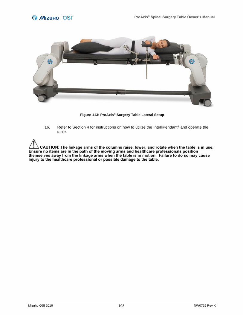
ProAxis® Spinal Surgery Table Owner’s Manual
108 Mizuho OSI 2016 NW0725 Rev K
Figure 113: ProAxis® Surgery Table Lateral Setup
16. Refer to Section 4 for instructions on how to utilize the IntelliPendant® and operate the table.
CAUTION: The linkage arms of the columns raise, lower, and rotate when the table is in use. Ensure no items are in the path of the moving arms and healthcare professionals position themselves away from the linkage arms when the table is in motion. Failure to do so may cause injury to the healthcare professional or possible damage to the table.
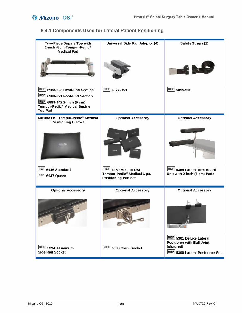
ProAxis® Spinal Surgery Table Owner’s Manual
109 Mizuho OSI 2016 NW0725 Rev K
8.4.1 Components Used for Lateral Patient Positioning
Two-Piece Supine Top with 2-inch (5cm)Tempur-Pedic®
Medical Pad
Universal Side Rail Adaptor (4)
Safety Straps (2)
6988-623 Head-End Section
6988-621 Foot-End Section
6988-442 2-inch (5 cm) Tempur-Pedic® Medical Supine Top Pad
6977-959 5855-550
Mizuho OSI Tempur-Pedic® Medical Positioning Pillows
Optional Accessory
Optional Accessory
6946 Standard
6947 Queen
6950 Mizuho OSI Tempur-Pedic® Medical 6 pc. Positioning Pad Set
5364 Lateral Arm Board Unit with 2-inch (5 cm) Pads
Optional Accessory
Optional Accessory
Optional Accessory
5394 Aluminum Side Rail Socket
5393 Clark Socket
5301 Deluxe Lateral Positioner with Ball Joint (pictured)
5300 Lateral Positioner Set
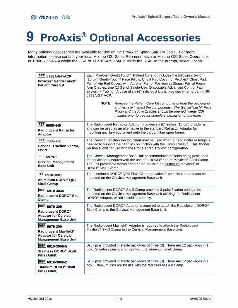
ProAxis® Spinal Surgery Table Owner’s Manual
110 Mizuho OSI 2016 NW0725 Rev K
9 ProAxis® Optional Accessories Many optional accessories are available for use on the ProAxis® Spinal Surgery Table. For more information, please contact your local Mizuho OSI Sales Representative or Mizuho OSI Sales Operations at 1-800-777-4574 within the USA or +1-510-429-1500 outside the USA. At the prompt, select Option 1.
6988A-GT-ACP
ProAxis® GentleTouch® Patient Care Kit
Each ProAxis® GentleTouch® Patient Care Kit includes the following: 6-inch (15 cm) GentleTouch® Face Pillow; Chest Pad Cover for ProAxis® Chest Pad; Pair of Hip Pad Covers with Aprons; Pair of Positioning Straps; Pair of Foam Arm Cradles; one (1) Set of Single-Use, Disposable Advanced Control Pad System™ Tubing. A case of six (6) individual kits is provided when ordering 6988A-GT-ACP.
NOTE: Remove the Patient Care Kit components from the packaging and visually inspect the components. The GentleTouch® Face Pillow and the Arm Cradles should be opened twenty (20) minutes prior to use for complete expansion of the foam.
6988-449
Radiolucent Retractor Adaptor
The Radiolucent Retractor Adaptor provides six (6) inches (15 cm) of side rail and can be used as an alternative to the standard Retractor Adaptor for mounting ancillary equipment onto the carbon fiber open frame.
6988-720
Cervical Traction Vector, Short
The Cervical Traction Vector, Short may be used when a head halter or tongs is needed to support the head in conjunction with the Torso Trolley®. This shorter version allows for use with the Prone Torso Trolley® configuration.
5979-1
Cervical Management Base Unit
The Cervical Management Base Unit accommodates patients being positioned for cervical procedures with the use of a DORO® and/or Mayfield® Skull Clamp. The unit provides a swivel adaptor for use with an aluminum Mayfield® or DORO® Skull Clamp.
6910-1001
Aluminum DORO® QR3 Skull Clamp
The aluminum DORO® QR3 Skull Clamp provides 3-point fixation and can be mounted on the Cervical Management Base Unit.
6910-3034
Radiolucent DORO® Skull Clamp
The Radiolucent DORO® Skull Clamp provides 3-point fixation and can be mounted on the Cervical Management Base Unit utilizing the Radiolucent DORO® Adaptor, which is sold separately.
5979-300
Radiolucent DORO® Adaptor for Cervical Management Base Unit
The Radiolucent DORO® Adaptor is required to attach the Radiolucent DORO® Skull Clamp to the Cervical Management Base Unit.
5979-200
Radiolucent Mayfield® Adaptor for Cervical Management Base Unit
The Radiolucent Mayfield® Adaptor is required to attach the Radiolucent Mayfield® Skull Clamp to the Cervical Management Base Unit.
6910-3006-5
Stainless DORO® Skull Pins (Adult)
Skull pins provided in sterile packages of three (3). There are 12 packages in 1 box. Stainless pins are for use with the aluminum skull clamp.
6910-3006-2
Titanium DORO® Skull Pins (Adult)
Skull pins provided in sterile packages of three (3). There are 12 packages in 1 box. Titanium pins are for use with the radiolucent skull clamp.
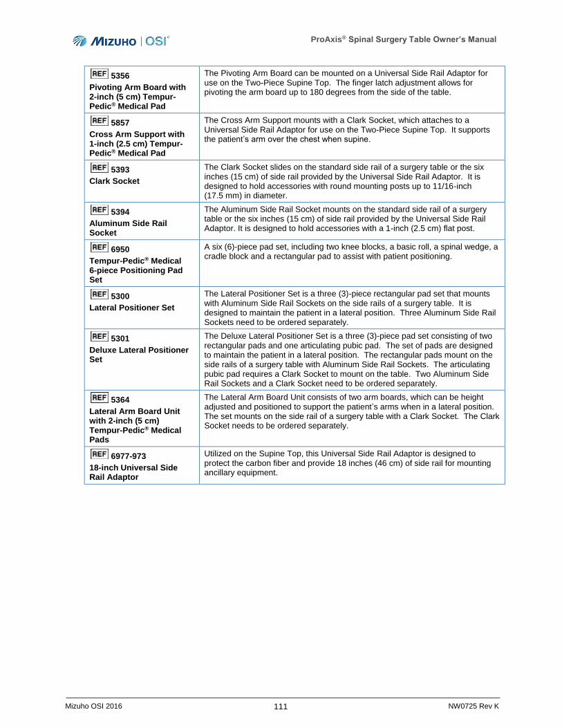
ProAxis® Spinal Surgery Table Owner’s Manual
111 Mizuho OSI 2016 NW0725 Rev K
5356
Pivoting Arm Board with 2-inch (5 cm) Tempur-Pedic® Medical Pad
The Pivoting Arm Board can be mounted on a Universal Side Rail Adaptor for use on the Two-Piece Supine Top. The finger latch adjustment allows for pivoting the arm board up to 180 degrees from the side of the table.
5857
Cross Arm Support with 1-inch (2.5 cm) Tempur-Pedic® Medical Pad
The Cross Arm Support mounts with a Clark Socket, which attaches to a Universal Side Rail Adaptor for use on the Two-Piece Supine Top. It supports the patient’s arm over the chest when supine.
5393
Clark Socket
The Clark Socket slides on the standard side rail of a surgery table or the six inches (15 cm) of side rail provided by the Universal Side Rail Adaptor. It is designed to hold accessories with round mounting posts up to 11/16-inch (17.5 mm) in diameter.
5394
Aluminum Side Rail Socket
The Aluminum Side Rail Socket mounts on the standard side rail of a surgery table or the six inches (15 cm) of side rail provided by the Universal Side Rail Adaptor. It is designed to hold accessories with a 1-inch (2.5 cm) flat post.
6950
Tempur-Pedic® Medical 6-piece Positioning Pad Set
A six (6)-piece pad set, including two knee blocks, a basic roll, a spinal wedge, a cradle block and a rectangular pad to assist with patient positioning.
5300
Lateral Positioner Set
The Lateral Positioner Set is a three (3)-piece rectangular pad set that mounts with Aluminum Side Rail Sockets on the side rails of a surgery table. It is designed to maintain the patient in a lateral position. Three Aluminum Side Rail Sockets need to be ordered separately.
5301
Deluxe Lateral Positioner Set
The Deluxe Lateral Positioner Set is a three (3)-piece pad set consisting of two rectangular pads and one articulating pubic pad. The set of pads are designed to maintain the patient in a lateral position. The rectangular pads mount on the side rails of a surgery table with Aluminum Side Rail Sockets. The articulating pubic pad requires a Clark Socket to mount on the table. Two Aluminum Side Rail Sockets and a Clark Socket need to be ordered separately.
5364
Lateral Arm Board Unit with 2-inch (5 cm) Tempur-Pedic® Medical Pads
The Lateral Arm Board Unit consists of two arm boards, which can be height adjusted and positioned to support the patient’s arms when in a lateral position. The set mounts on the side rail of a surgery table with a Clark Socket. The Clark Socket needs to be ordered separately.
6977-973
18-inch Universal Side Rail Adaptor
Utilized on the Supine Top, this Universal Side Rail Adaptor is designed to protect the carbon fiber and provide 18 inches (46 cm) of side rail for mounting ancillary equipment.
ProAxis® Spinal Surgery Table Owner’s Manual
112 Mizuho OSI 2016 NW0725 Rev K
10 Cleaning, Storage, and Maintenance
10.1 Cleaning and Disinfecting
NOTE: Clean and disinfect the ProAxis® Spinal Surgery Table after each use.
10.1.1 Table Exterior
The exterior surface should be regularly wiped clean with a mild detergent solution and wiped dry with a soft lint-free cloth. This includes the table pad, table top, and all components and accessories.
Care should be taken to avoid exposing the table to excessive moisture. Flooding, fogging, or steam cleaning should not be used to clean the table.
CAUTION: Never pour any liquid directly onto the ProAxis® Spinal Surgery Table. Never subject the ProAxis® Spinal Surgery Table to an equipment washing machine or any pressurized stream of water.
Blood or other fluids, etc., if allowed to remain on the table for a long period of time, will require special cleaning to remove. A 5% acetic acid solution (or white vinegar) is especially good for this purpose.
NOTE: Use of iodophors will cause staining.
To remove staining or discoloration of plated or stainless steel surfaces, clean with a commercial cleaning compound labeled for stainless steel and then buff the surface by hand.
To disinfect exterior surfaces, use a quaternary ammonium disinfectant compound according to manufacturer's directions for use. Wipe dry with a soft lint-free cloth.
NOTE: Failure to thoroughly dry the surface after cleaning and disinfecting may result in rust.
WARNING: Should it be necessary to disconnect the spars from the Head-End of the table for cleaning and disinfecting purposes, do not use excessive force to disconnect the spars. If after unlocking the spar lock, the spar does not disconnect with hand force, seek assistance from qualified service personnel. Failure to properly disconnect the spars may cause harm to the healthcare professional or the device.
10.1.2 ProneView® Helmet and Mirror System
Clean the ProneView® Helmet and Mirror after each use by spraying and wiping with a germicidal cleaner then wipe dry, or wash with anti-bacterial soap and water, rinse, then wipe dry.
NOTE: Do not autoclave the ProneView® Helmet or Mirror Platform.
ProAxis® Spinal Surgery Table Owner’s Manual
113 Mizuho OSI 2016 NW0725 Rev K
10.1.3 Mizuho OSI Tempur-Pedic® Medical Pads
NOTE: The Mizuho OSI Tempur-Pedic® Medical Pads should always be stored in a flat position. The pads can become stiff in cold temperatures and can crack and break if in a rolled position. It is important that you allow the pads to warm to room temperature before attempting to use or handle.
When handling a Tempur-Pedic® Medical Pad, always grasp by the entire thickness of the pad.
CAUTION: DO NOT lift, slide, or carry Mizuho OSI Tempur-Pedic® Medical Pads by grabbing the fabric cover. The cover may tear or rip. Do not leave the pads folded, as the pad construction may take a permanent crease in the bent area. The permanent crease will cause performance issues of the pad and may cause patient harm or injury.
The pads are intended to be cleaned in place. They do not need to be rotated or removed.
Clean with standard hospital disinfectants labeled for use on table pads. Always dilute and rinse per manufacturer’s label instructions. Wipe dry with a lint free cloth. DO NOT soak or autoclave the pads.
NOTE: The use of bleach or highly concentrated chemicals may discolor the cover and will void the warranty on the pad.
When cleaning the bottom of the pad or the table top, simply lift one end of the pad, and fold it over onto the other end. Clean the pad or the table top, wipe dry with a lint free cloth then reposition the pad to flat on the table top.
10.2 Storage
When not in use, the ProAxis® Spinal Surgery Table should be stored in a clean, dry environment.
The following conditions are required of the shipping and/or storage environment:
Ambient temperature -4°F (-20°C) to + 122°F (50°C).
Relative humidity from 10% to 95%, non-condensing.
Atmospheric pressure from 75 to 105 kPa.
When in storage, the table cover provided serves as a dust cover and should be used. Also, to ensure that the battery is always fully charged and ready for use, store the table connected to AC power that matches the ratings on the manufacturer’s label on the Foot-End column of the table (Figure 10, page 18).
10.3 Maintenance
Cleaning the table surfaces and table pad after each use will assure many years of trouble-free service.
Mizuho OSI recommends customers inspect and maintain Tempur-Pedic® pads per Mizuho OSI’s pad inspection program guidelines. Contact your Mizuho OSI sales representative or Mizuho OSI Services for a pad inspection checklist.
All components are lubricated for life at the factory and no other lubrication is required.
Preventative Maintenance is required every six (6) months. Contact Mizuho OSI Services for a complete Preventative Maintenance Checklist.

ProAxis® Spinal Surgery Table Owner’s Manual
114 Mizuho OSI 2016 NW0725 Rev K
For detailed repair information or to order replacement parts, call or contact via the web Mizuho OSI Services:
1-800-777-4674, Option 2 (for calls within the USA)
+1-510-429-1500, Option 2 (for calls outside the USA)
+1-510-429-8324 (Fax)
www.mizuhosi.com
Mizuho OSI Services is available from 5 AM to 5 PM Pacific Time, Monday through Friday. Please leave a message after normal business hours.
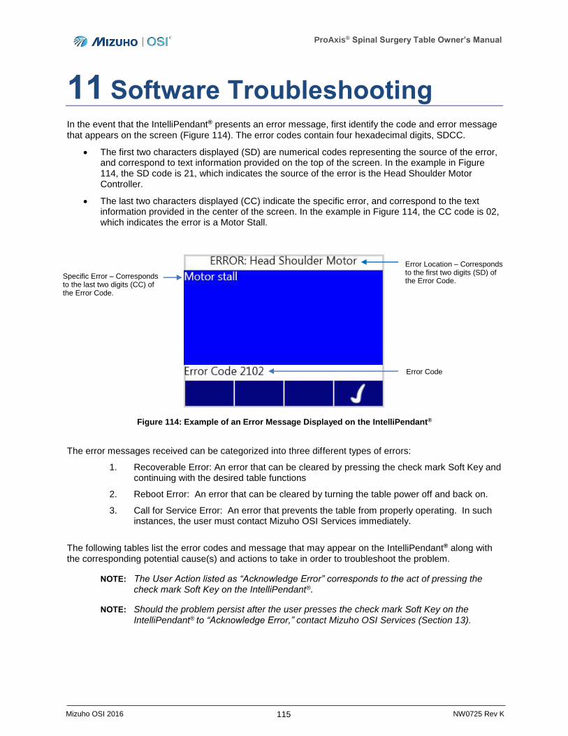
ProAxis® Spinal Surgery Table Owner’s Manual
115 Mizuho OSI 2016 NW0725 Rev K
11 Software Troubleshooting In the event that the IntelliPendant® presents an error message, first identify the code and error message that appears on the screen (Figure 114). The error codes contain four hexadecimal digits, SDCC.
The first two characters displayed (SD) are numerical codes representing the source of the error, and correspond to text information provided on the top of the screen. In the example in Figure 114, the SD code is 21, which indicates the source of the error is the Head Shoulder Motor Controller.
The last two characters displayed (CC) indicate the specific error, and correspond to the text information provided in the center of the screen. In the example in Figure 114, the CC code is 02, which indicates the error is a Motor Stall.
Figure 114: Example of an Error Message Displayed on the IntelliPendant®
The error messages received can be categorized into three different types of errors:
1. Recoverable Error: An error that can be cleared by pressing the check mark Soft Key and continuing with the desired table functions
2. Reboot Error: An error that can be cleared by turning the table power off and back on.
3. Call for Service Error: An error that prevents the table from properly operating. In such instances, the user must contact Mizuho OSI Services immediately.
The following tables list the error codes and message that may appear on the IntelliPendant® along with the corresponding potential cause(s) and actions to take in order to troubleshoot the problem.
NOTE: The User Action listed as “Acknowledge Error” corresponds to the act of pressing the check mark Soft Key on the IntelliPendant®.
NOTE: Should the problem persist after the user presses the check mark Soft Key on the IntelliPendant® to “Acknowledge Error,” contact Mizuho OSI Services (Section 13).
Error Location – Corresponds to the first two digits (SD) of the Error Code.
Specific Error – Corresponds to the last two digits (CC) of the Error Code.
Error Code

ProAxis® Spinal Surgery Table Owner’s Manual
116 Mizuho OSI 2016 NW0725 Rev K
CODE (SD) ERROR SOURCE AND DETAIL 00 None – general
10 Main Controller
21 Motor Controller, Head Shoulder
22 Motor Controller, Head Elbow
23 Motor Controller, Head Wrist
24 Motor Controller, Foot Shoulder
25 Motor Controller, Foot Elbow
26 Motor Controller, Foot Wrist
27 Motor Controller, Tilt
30 Chest Tray
41 Floor Lock, Head-End
42 Floor Lock, Foot-End
50 Hand Pendant
60 Auxiliary Control Panel
70 Pump Controller
CODE
(SD) CODE
(CC) ERROR MESSAGE POTENTIAL CAUSE(S) USER ACTION(S)
00 General Errors
C0 Board reset (Power on) Board was powered on. Acknowledge error.
C1 Brown out reset Board temporarily lost power. Acknowledge error.
C2 Watchdog reset Internal software error. Acknowledge error.
C3 Software reset Internal software error. Acknowledge error.
C4 External reset Internal software error. Acknowledge error.
C5 Illegal opcode reset Internal software error. Acknowledge error.
C6 Trap conflict reset Internal software error. Acknowledge error.
C7 Unknown reset Internal software error. Acknowledge error.
C8 Stack overflow reset Internal software error. Acknowledge error.
C9 Stack underflow reset Internal software error. Acknowledge error.
D0 Low logic supply voltage The logic voltage into the board is low.
Acknowledge error.
Contact Mizuho OSI Services.
D2 Low drive supply voltage The drive voltage into the board is low.
Acknowledge error.
Contact Mizuho OSI Services.
E0 Invalid state transition Internal software error. Acknowledge error.

ProAxis® Spinal Surgery Table Owner’s Manual
117 Mizuho OSI 2016 NW0725 Rev K
CODE
(SD) CODE
(CC) ERROR MESSAGE POTENTIAL CAUSE(S) USER ACTION(S)
10 Main Controller Errors
23 Move not stopped User requested motion but the system timed out waiting for one or more boards to be ready.
Acknowledge error.
25 Head wrist maximum height The table moved past the allowed maximum height of the Head-End wrist.
Acknowledge error. Contact Mizuho OSI Services.
26 Foot wrist maximum height The table moved past the allowed maximum height of the Foot-End wrist.
Acknowledge error. Contact Mizuho OSI Services.
27 Head wrist minimum height The table moved past the allowed minimum height of the Head-End wrist.
Acknowledge error. Contact Mizuho OSI Services.
28 Foot wrist minimum height The table moved past the allowed minimum height of the Foot-End wrist.
Acknowledge error. Contact Mizuho OSI Services.
29 Minimum hinge height The table moved past the allowed minimum height of the hinge.
Acknowledge error. Contact Mizuho OSI Services.
2A Maximum hinge angle The table moved past the allowed maximum hinge angle.
Acknowledge error. Contact Mizuho OSI Services.
2B Minimum hinge angle The table moved past the allowed minimum hinge angle.
Acknowledge error. Contact Mizuho OSI Services.
2C Maximum tilt angle The table moved past the allowed maximum tilt angle.
Acknowledge error. Use tilt to move table back into allowed angle.
2D Minimum tilt angle The table moved past the allowed minimum tilt angle.
Acknowledge error. Use tilt to move table back into allowed angle.
2E Table not ready to start new motion
The user requested motion but one of the boards was not ready for motion for a period that exceeded the timeout.
Turn table power off and back on.
41 Communication lost with Motor board
One or more motor boards are not communicating with the main controller.
Turn table power off and back on. Contact Mizuho OSI Services.
42 Communication lost with Chest Tray board
The chest tray board is not communicating with the main controller.
Turn table power off and back on. Contact Mizuho OSI Services.
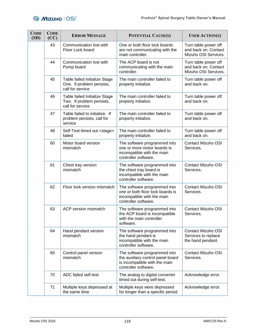
ProAxis® Spinal Surgery Table Owner’s Manual
118 Mizuho OSI 2016 NW0725 Rev K
CODE
(SD) CODE
(CC) ERROR MESSAGE POTENTIAL CAUSE(S) USER ACTION(S)
43 Communication lost with Floor Lock board
One or both floor lock boards are not communicating with the main controller.
Turn table power off and back on. Contact Mizuho OSI Services.
44 Communication lost with Pump board
The ACP board is not communicating with the main controller.
Turn table power off and back on. Contact Mizuho OSI Services.
45 Table failed Initialize Stage One. If problem persists, call for service
The main controller failed to properly initialize.
Turn table power off and back on.
46 Table failed Initialize Stage Two. If problem persists, call for service
The main controller failed to properly initialize.
Turn table power off and back on.
47 Table failed to initialize. If problem persists, call for service
The main controller failed to properly initialize.
Turn table power off and back on.
48 Self-Test timed out <stage> failed
The main controller failed to properly initialize.
Turn table power off and back on.
60 Motor board version mismatch
The software programmed into one or more motor boards is incompatible with the main controller software.
Contact Mizuho OSI Services.
61 Chest tray version mismatch
The software programmed into the chest tray board is incompatible with the main controller software.
Contact Mizuho OSI Services.
62 Floor lock version mismatch The software programmed into one or both floor lock boards is incompatible with the main controller software.
Contact Mizuho OSI Services.
63 ACP version mismatch The software programmed into the ACP board is incompatible with the main controller software.
Contact Mizuho OSI Services.
64 Hand pendant version mismatch
The software programmed into the hand pendant is incompatible with the main controller software.
Contact Mizuho OSI Services to replace the hand pendant.
65 Control panel version mismatch
The software programmed into the auxiliary control panel board is incompatible with the main controller software.
Contact Mizuho OSI Services.
70 ADC failed self-test The analog to digital converter timed out during self-test.
Acknowledge error.
71 Multiple keys depressed at the same time
Multiple keys were depressed for longer than a specific period.
Acknowledge error.

ProAxis® Spinal Surgery Table Owner’s Manual
119 Mizuho OSI 2016 NW0725 Rev K
CODE
(SD) CODE
(CC) ERROR MESSAGE POTENTIAL CAUSE(S) USER ACTION(S)
72 Possible stuck key on Pendant or Control Panel. If problem persists, call for service.
A single key was still depressed for longer than a specific period after a multiple key press.
Acknowledge error.
A0 Clock battery failure The small coin-cell battery on the main controller board is not working.
Acknowledge error.
Contact Mizuho OSI Services to replace battery.
A1 Clock oscillator not running Internal software error. Acknowledge error.
A2 Clock not incrementing Internal software error. Acknowledge error.
A3 Clock failed self-test Internal software error. Acknowledge error.
A4 Clock communication error – Invalid request
Internal software error. Acknowledge error.
A5 Clock communication error – Queue full
Internal software error. Acknowledge error.
A6 Clock failed to initialize Internal software error. Acknowledge error.
A7 RTC SRAM checksum failure (internal error)
Internal software error. Acknowledge error.
A8 RTC EEPROM checksum failure (internal error)
Internal software error. Acknowledge error.
A9 RTC SRAM invalid hinge mode (internal error)
Internal software error. Acknowledge error.
AA RTC SRAM invalid IMS state (internal error)
Internal software error. Acknowledge error.
AB RTC SRAM invalid storage mode (internal error)
Internal software error. Acknowledge error.
AC RTC SRAM invalid version (internal error)
Internal software error. Acknowledge error.
B0 Reduce load, cycle Table power Call service if error persists OVERLOAD!
The IMS has detected a loading condition that exceeds the red threshold.
Turn table power off and back on. Contact Mizuho OSI Services.
B1 Reduce load Turn table off and back on OVERLOAD!
The IMS has detected a loading condition that exceeds the yellow threshold.
Turn table power off and back on.
B2 Table is still overloaded after cycling power. Continue operation?
The IMS has detected a loading condition that still exceeds the yellow threshold after a reboot.
Acknowledge the condition.
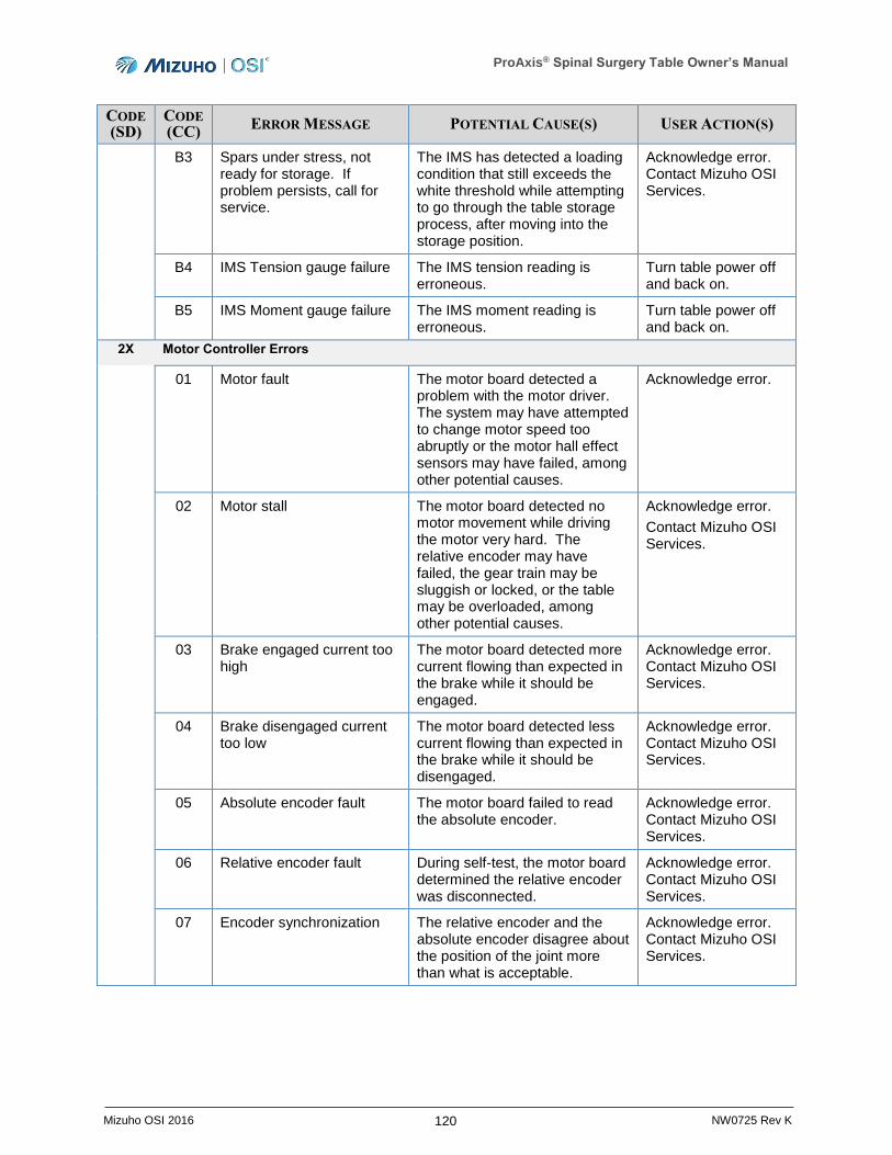
ProAxis® Spinal Surgery Table Owner’s Manual
120 Mizuho OSI 2016 NW0725 Rev K
CODE
(SD) CODE
(CC) ERROR MESSAGE POTENTIAL CAUSE(S) USER ACTION(S)
B3 Spars under stress, not ready for storage. If problem persists, call for service.
The IMS has detected a loading condition that still exceeds the white threshold while attempting to go through the table storage process, after moving into the storage position.
Acknowledge error. Contact Mizuho OSI Services.
B4 IMS Tension gauge failure The IMS tension reading is erroneous.
Turn table power off and back on.
B5 IMS Moment gauge failure The IMS moment reading is erroneous.
Turn table power off and back on.
2X Motor Controller Errors
01 Motor fault The motor board detected a problem with the motor driver. The system may have attempted to change motor speed too abruptly or the motor hall effect sensors may have failed, among other potential causes.
Acknowledge error.
02 Motor stall The motor board detected no motor movement while driving the motor very hard. The relative encoder may have failed, the gear train may be sluggish or locked, or the table may be overloaded, among other potential causes.
Acknowledge error.
Contact Mizuho OSI Services.
03 Brake engaged current too high
The motor board detected more current flowing than expected in the brake while it should be engaged.
Acknowledge error. Contact Mizuho OSI Services.
04 Brake disengaged current too low
The motor board detected less current flowing than expected in the brake while it should be disengaged.
Acknowledge error. Contact Mizuho OSI Services.
05 Absolute encoder fault The motor board failed to read the absolute encoder.
Acknowledge error. Contact Mizuho OSI Services.
06 Relative encoder fault During self-test, the motor board determined the relative encoder was disconnected.
Acknowledge error. Contact Mizuho OSI Services.
07 Encoder synchronization The relative encoder and the absolute encoder disagree about the position of the joint more than what is acceptable.
Acknowledge error. Contact Mizuho OSI Services.
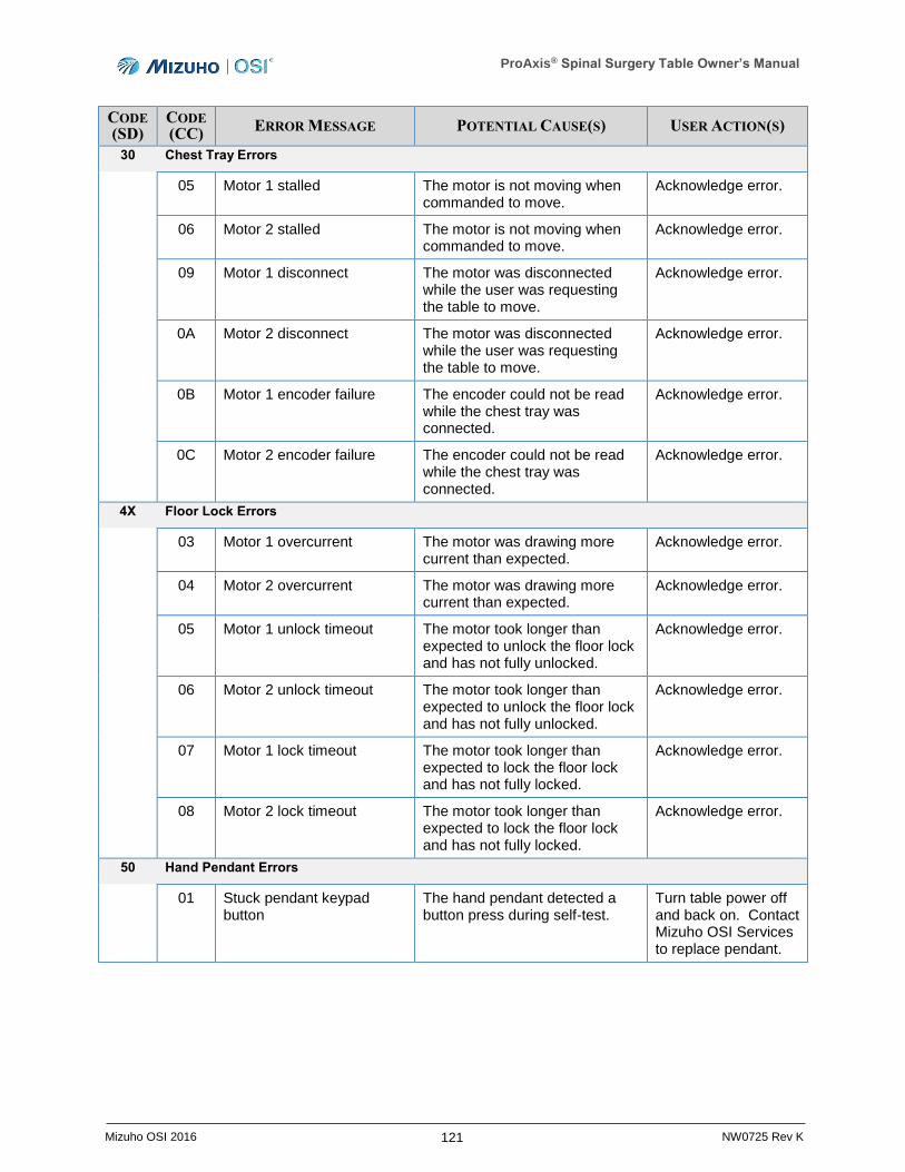
ProAxis® Spinal Surgery Table Owner’s Manual
121 Mizuho OSI 2016 NW0725 Rev K
CODE
(SD) CODE
(CC) ERROR MESSAGE POTENTIAL CAUSE(S) USER ACTION(S)
30 Chest Tray Errors
05 Motor 1 stalled The motor is not moving when commanded to move.
Acknowledge error.
06 Motor 2 stalled The motor is not moving when commanded to move.
Acknowledge error.
09 Motor 1 disconnect The motor was disconnected while the user was requesting the table to move.
Acknowledge error.
0A Motor 2 disconnect The motor was disconnected while the user was requesting the table to move.
Acknowledge error.
0B Motor 1 encoder failure The encoder could not be read while the chest tray was connected.
Acknowledge error.
0C Motor 2 encoder failure The encoder could not be read while the chest tray was connected.
Acknowledge error.
4X Floor Lock Errors
03 Motor 1 overcurrent The motor was drawing more current than expected.
Acknowledge error.
04 Motor 2 overcurrent The motor was drawing more current than expected.
Acknowledge error.
05 Motor 1 unlock timeout The motor took longer than expected to unlock the floor lock and has not fully unlocked.
Acknowledge error.
06 Motor 2 unlock timeout The motor took longer than expected to unlock the floor lock and has not fully unlocked.
Acknowledge error.
07 Motor 1 lock timeout The motor took longer than expected to lock the floor lock and has not fully locked.
Acknowledge error.
08 Motor 2 lock timeout The motor took longer than expected to lock the floor lock and has not fully locked.
Acknowledge error.
50 Hand Pendant Errors
01 Stuck pendant keypad button
The hand pendant detected a button press during self-test.
Turn table power off and back on. Contact Mizuho OSI Services to replace pendant.
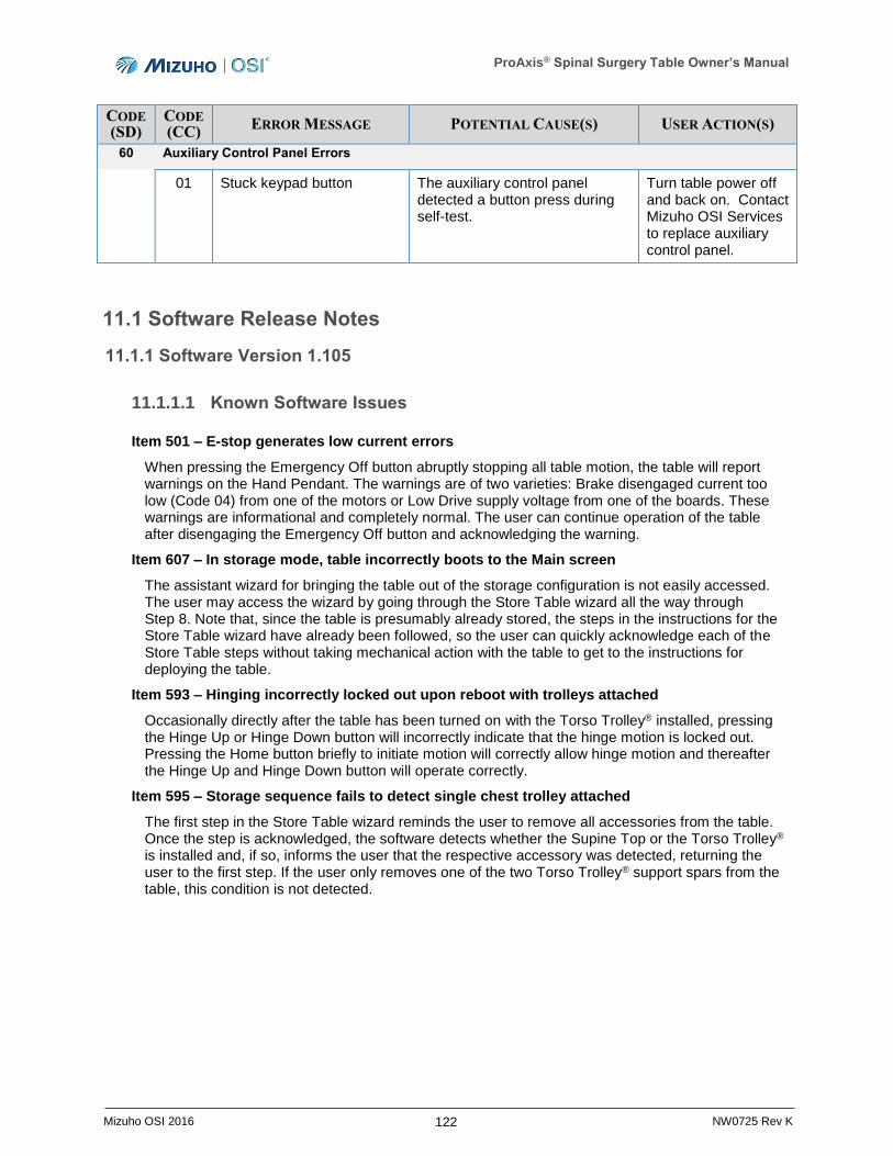
ProAxis® Spinal Surgery Table Owner’s Manual
122 Mizuho OSI 2016 NW0725 Rev K
CODE
(SD) CODE
(CC) ERROR MESSAGE POTENTIAL CAUSE(S) USER ACTION(S)
60 Auxiliary Control Panel Errors
01 Stuck keypad button The auxiliary control panel detected a button press during self-test.
Turn table power off and back on. Contact Mizuho OSI Services to replace auxiliary control panel.
11.1 Software Release Notes
11.1.1 Software Version 1.105
11.1.1.1 Known Software Issues
Item 501 – E-stop generates low current errors
When pressing the Emergency Off button abruptly stopping all table motion, the table will report warnings on the Hand Pendant. The warnings are of two varieties: Brake disengaged current too low (Code 04) from one of the motors or Low Drive supply voltage from one of the boards. These warnings are informational and completely normal. The user can continue operation of the table after disengaging the Emergency Off button and acknowledging the warning.
Item 607 – In storage mode, table incorrectly boots to the Main screen
The assistant wizard for bringing the table out of the storage configuration is not easily accessed. The user may access the wizard by going through the Store Table wizard all the way through Step 8. Note that, since the table is presumably already stored, the steps in the instructions for the Store Table wizard have already been followed, so the user can quickly acknowledge each of the Store Table steps without taking mechanical action with the table to get to the instructions for deploying the table.
Item 593 – Hinging incorrectly locked out upon reboot with trolleys attached
Occasionally directly after the table has been turned on with the Torso Trolley® installed, pressing the Hinge Up or Hinge Down button will incorrectly indicate that the hinge motion is locked out. Pressing the Home button briefly to initiate motion will correctly allow hinge motion and thereafter the Hinge Up and Hinge Down button will operate correctly.
Item 595 – Storage sequence fails to detect single chest trolley attached
The first step in the Store Table wizard reminds the user to remove all accessories from the table. Once the step is acknowledged, the software detects whether the Supine Top or the Torso Trolley® is installed and, if so, informs the user that the respective accessory was detected, returning the user to the first step. If the user only removes one of the two Torso Trolley® support spars from the table, this condition is not detected.

ProAxis® Spinal Surgery Table Owner’s Manual
123 Mizuho OSI 2016 NW0725 Rev K
11.1.2 Software Version 1.110
11.1.2.1 Software Enhancements
Language Support
The Hand Pendant now supports the English, French, Italian, German, and Spanish languages. Through a menu selection, the user may change the display language at any time. The language setting is preserved when the table is powered off.
Units Support
The Hand Pendant now supports displaying the table height in inches or centimeters. Through a menu selection, the user may change the units in which the table height is displayed at any time. The units setting is preserved when the table is powered off.
Independent Monitoring System Notifications
The table notifies the user when the Independent Monitoring System detects that the table is overloaded. Previously, even momentary loading conditions that occur, for example, when a user jumps onto the table configured for prone surgery, could lead to these notifications. The table now reduces the occurrence of these nuisance notifications.
11.1.2.2 Resolved Software Issues
Item 607 – In storage mode, table incorrectly boots to the Main screen
The assistant wizard for bringing the table out of the storage configuration was not easily accessed. This is resolved in version 1.110 so that when the table is powered on in the storage configuration, the hand pendant displays the Ready to Store/Undo screen.
Item 593 – Hinging incorrectly locked out upon reboot with trolleys attached
Previously, occasionally directly after the table has been turned on with the Torso Trolley® installed, pressing the Hinge Up or Hinge Down button would incorrectly indicate that the hinge motion is locked out. This is resolved in version 1.110.
Item 595 – Storage sequence fails to detect single chest trolley attached
The first step in the Store Table wizard reminds the user to remove all accessories from the table. Once the step is acknowledged, the software detects whether the Supine Top or the Torso Trolley® is installed and, if so, informs the user that the respective accessory was detected, returning the user to the first step. Previously, if the user only removes one of the two Torso Trolley® support spars from the table, this condition is not detected. This condition is now detected in version 1.110 and the software informs the user that the Torso Trolley® was detected.
11.1.2.3 Known Software Issues
Item 501 – E-stop generates low current errors
When pressing the Emergency Off button abruptly stopping all table motion, the table will report warnings on the Hand Pendant. The warnings are of two varieties: Brake disengaged current too low (Code 04) from one of the motors or Low Drive supply voltage from one of the boards. These warnings are informational and completely normal. The user can continue operation of the table after disengaging the Emergency Off button and acknowledging the warning.
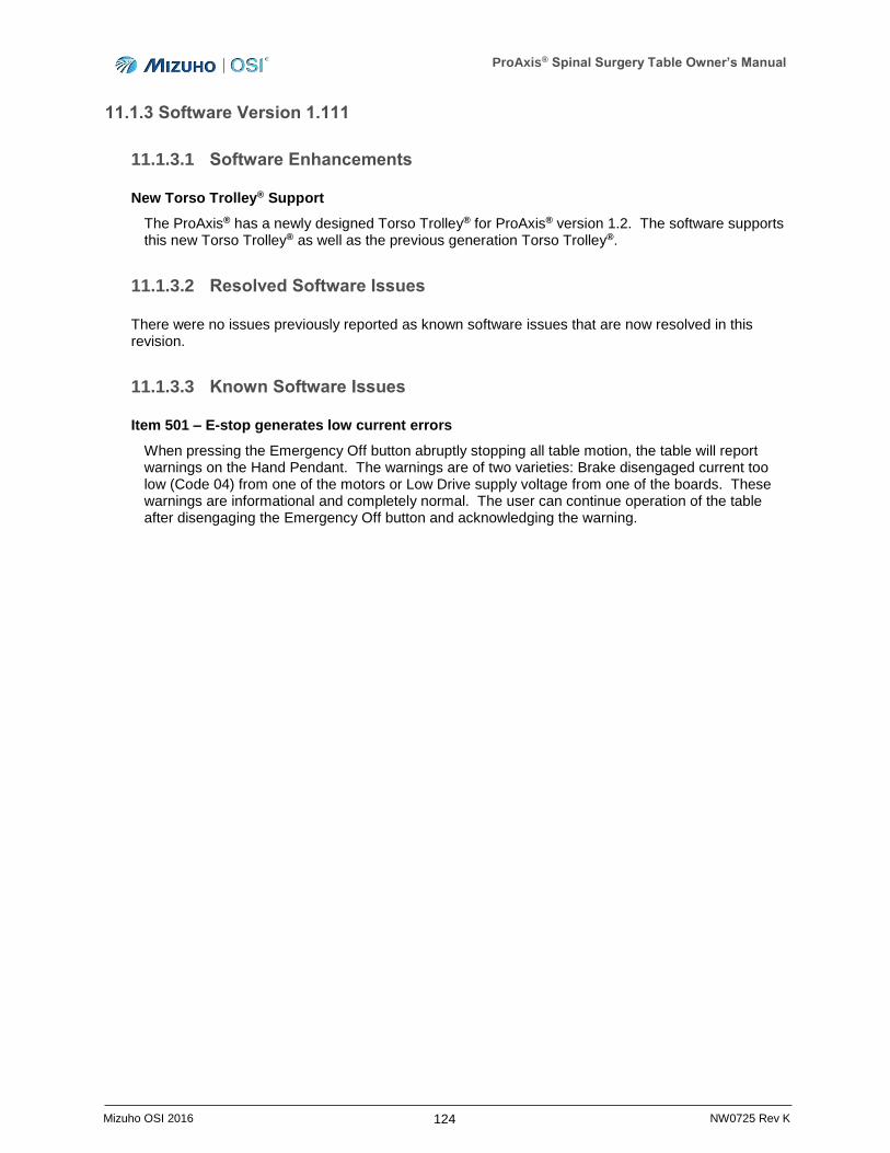
ProAxis® Spinal Surgery Table Owner’s Manual
124 Mizuho OSI 2016 NW0725 Rev K
11.1.3 Software Version 1.111
11.1.3.1 Software Enhancements
New Torso Trolley® Support
The ProAxis® has a newly designed Torso Trolley® for ProAxis® version 1.2. The software supports this new Torso Trolley® as well as the previous generation Torso Trolley®.
11.1.3.2 Resolved Software Issues
There were no issues previously reported as known software issues that are now resolved in this revision.
11.1.3.3 Known Software Issues
Item 501 – E-stop generates low current errors
When pressing the Emergency Off button abruptly stopping all table motion, the table will report warnings on the Hand Pendant. The warnings are of two varieties: Brake disengaged current too low (Code 04) from one of the motors or Low Drive supply voltage from one of the boards. These warnings are informational and completely normal. The user can continue operation of the table after disengaging the Emergency Off button and acknowledging the warning.
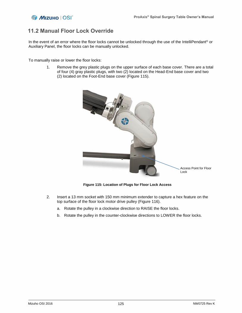
ProAxis® Spinal Surgery Table Owner’s Manual
125 Mizuho OSI 2016 NW0725 Rev K
11.2 Manual Floor Lock Override
In the event of an error where the floor locks cannot be unlocked through the use of the IntelliPendant® or Auxiliary Panel, the floor locks can be manually unlocked.
To manually raise or lower the floor locks:
1. Remove the grey plastic plugs on the upper surface of each base cover. There are a total of four (4) gray plastic plugs, with two (2) located on the Head-End base cover and two (2) located on the Foot-End base cover (Figure 115).
Figure 115: Location of Plugs for Floor Lock Access
2. Insert a 13 mm socket with 150 mm minimum extender to capture a hex feature on the top surface of the floor lock motor drive pulley (Figure 116).
a. Rotate the pulley in a clockwise direction to RAISE the floor locks.
b. Rotate the pulley in the counter-clockwise directions to LOWER the floor locks.
Access Point for Floor Lock
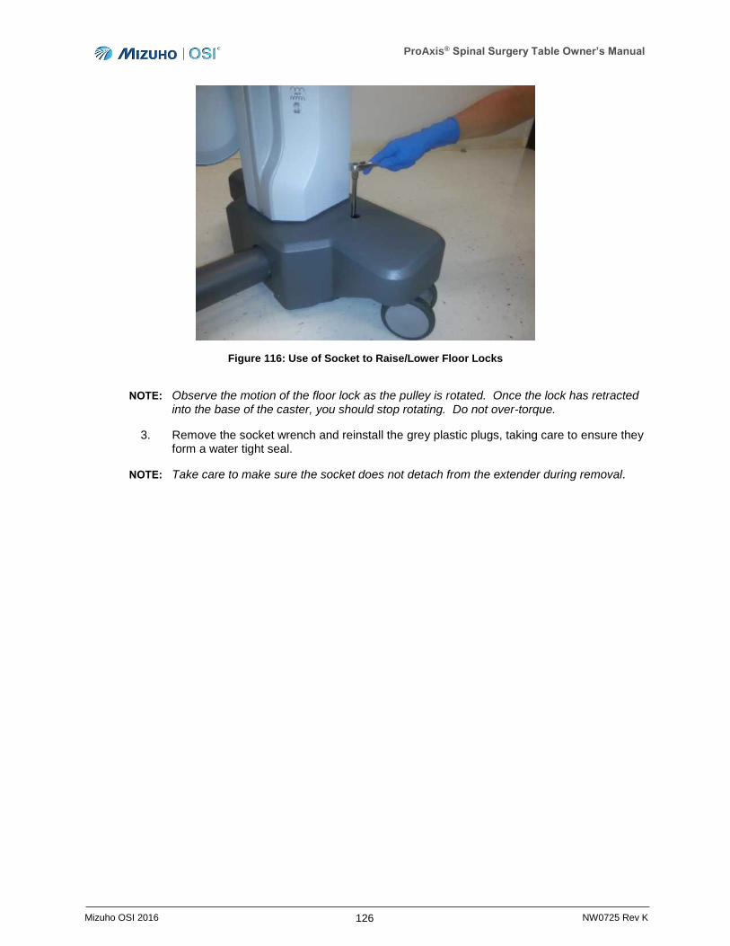
ProAxis® Spinal Surgery Table Owner’s Manual
126 Mizuho OSI 2016 NW0725 Rev K
Figure 116: Use of Socket to Raise/Lower Floor Locks
NOTE: Observe the motion of the floor lock as the pulley is rotated. Once the lock has retracted into the base of the caster, you should stop rotating. Do not over-torque.
3. Remove the socket wrench and reinstall the grey plastic plugs, taking care to ensure they form a water tight seal.
NOTE: Take care to make sure the socket does not detach from the extender during removal.

ProAxis® Spinal Surgery Table Owner’s Manual
127 Mizuho OSI 2016 NW0725 Rev K
12 Electrical System
12.1 Description
The electrical system provides control of all the table functions and is comprised of the following:
Detachable Power Cord
Power Switch
Power/Charging Indicator
Circuit Breakers
The Emergency Stop button
IntelliPendant®
Batteries
12.2 Component Identification and Function
12.2.1 Detachable Power Cord
The table is equipped with a standard IEC Power Cord with the appropriate hospital grade connector. The Power Cord is connected to the table at the IEC power receptacle located on the inside of the Head-End base near the Power Switch. Do not store material near the power inlet nor otherwise impede access to the detachable power cord.
WARNING: Ensure the IEC Power Cord provided is utilized and connected to a properly grounded receptacle that meets the input voltage requirements identified on the manufacturer’s label on the Foot-End column of the table. Failure to do so may result in harm to the patient, healthcare professional, or the device.
12.2.2 Power Switch
A Power Switch is located on the Head-End base of the table. When the switch is illuminated green, it indicates that the table is powered ON (Figure 117).
12.2.3 Power/Charging Indicator
Two indicators (located in the Power Inlet Assembly) provide status of the AC and Battery charger. When connected to AC Power, the AC Indicator will illuminate green. The batteries are automatically charged if AC is present. The Battery Indicator will illuminate yellow if the batteries are charging and then turn green when they are fully charged (Figure 117).
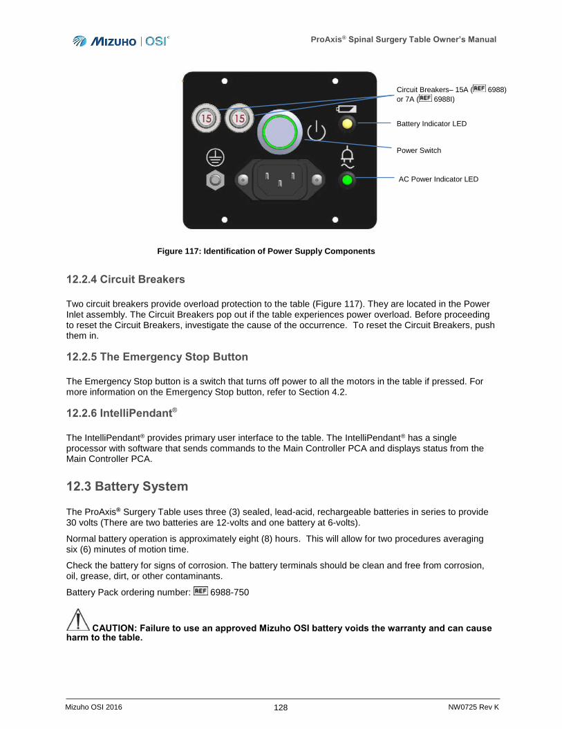
ProAxis® Spinal Surgery Table Owner’s Manual
128 Mizuho OSI 2016 NW0725 Rev K
Figure 117: Identification of Power Supply Components
12.2.4 Circuit Breakers
Two circuit breakers provide overload protection to the table (Figure 117). They are located in the Power Inlet assembly. The Circuit Breakers pop out if the table experiences power overload. Before proceeding to reset the Circuit Breakers, investigate the cause of the occurrence. To reset the Circuit Breakers, push them in.
12.2.5 The Emergency Stop Button
The Emergency Stop button is a switch that turns off power to all the motors in the table if pressed. For more information on the Emergency Stop button, refer to Section 4.2.
12.2.6 IntelliPendant®
The IntelliPendant® provides primary user interface to the table. The IntelliPendant® has a single processor with software that sends commands to the Main Controller PCA and displays status from the Main Controller PCA.
12.3 Battery System
The ProAxis® Surgery Table uses three (3) sealed, lead-acid, rechargeable batteries in series to provide 30 volts (There are two batteries are 12-volts and one battery at 6-volts).
Normal battery operation is approximately eight (8) hours. This will allow for two procedures averaging six (6) minutes of motion time.
Check the battery for signs of corrosion. The battery terminals should be clean and free from corrosion, oil, grease, dirt, or other contaminants.
Battery Pack ordering number: 6988-750
CAUTION: Failure to use an approved Mizuho OSI battery voids the warranty and can cause harm to the table.
Battery Indicator LED
AC Power Indicator LED
Circuit Breakers– 15A ( 6988)
or 7A ( 6988I)
Power Switch

ProAxis® Spinal Surgery Table Owner’s Manual
129 Mizuho OSI 2016 NW0725 Rev K
12.3.1 Charging the Batteries
When the Battery Status symbol on the IntelliPendant® indicates less charge, the batteries require charging. To charge, plug the Power Cord into an appropriate hospital grade AC outlet.
It is imperative that they be charged within 6 months of storage, otherwise permanent loss of capacity might occur as a result of sulfation. Using the table while on AC power will also allow the batteries to charge.
The battery will be fully charged from a completely depleted state in 24 hours. If the battery fails to hold a charge it should be replaced (refer to Section 13).
CAUTION: If the table is running on battery and is not charged when this Battery Status
Symbol displays on the IntelliPendant®, the table will run out of charge and stop functioning.
12.3.2 Replacing the Batteries
When replacing the batteries for the ProAxis® Spinal Surgery Table:
Replace only with an identical type and size battery pack.
Replace all three batteries at the same time.
At a minimum, replace all batteries once every five (5) years.
NOTE: Failure to use an approved Mizuho OSI battery voids the warranty and can cause harm to the table.
WARNING: Electrical shock hazard exists with access covers removed; use caution when working in exposed areas. Servicing and replacement of batteries should only be performed by trained personnel.
To remove and replace the batteries:
1. Raise the height of the table to its highest position.
2. Ensure that the Power Switch is pressed to OFF and unplug the Power Cord from the wall outlet.
NOTE: Disconnect batteries only with Power Cord unplugged and Power Switch pressed to OFF.
3. Remove Cover, Head-End Column, Inner. Next, remove the Cover Assembly, Head-End Base, Left.
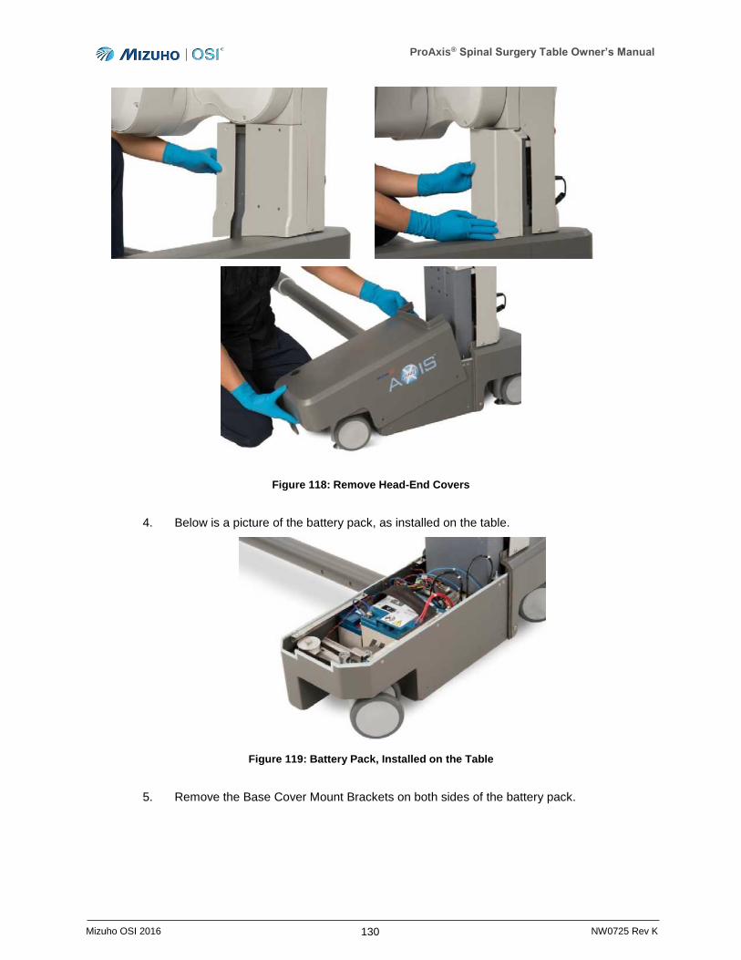
ProAxis® Spinal Surgery Table Owner’s Manual
130 Mizuho OSI 2016 NW0725 Rev K
Figure 118: Remove Head-End Covers
4. Below is a picture of the battery pack, as installed on the table.
Figure 119: Battery Pack, Installed on the Table
5. Remove the Base Cover Mount Brackets on both sides of the battery pack.
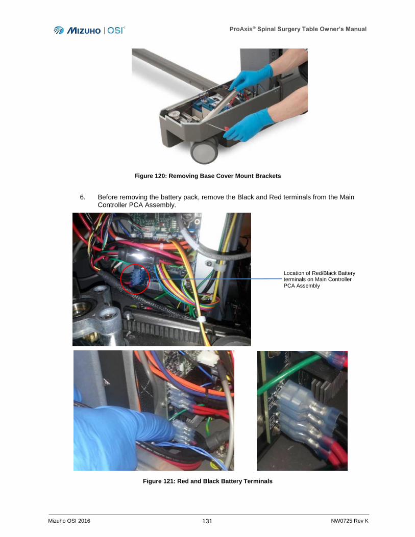
ProAxis® Spinal Surgery Table Owner’s Manual
131 Mizuho OSI 2016 NW0725 Rev K
Figure 120: Removing Base Cover Mount Brackets
6. Before removing the battery pack, remove the Black and Red terminals from the Main Controller PCA Assembly.
Figure 121: Red and Black Battery Terminals
Location of Red/Black Battery terminals on Main Controller PCA Assembly
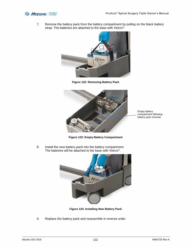
ProAxis® Spinal Surgery Table Owner’s Manual
132 Mizuho OSI 2016 NW0725 Rev K
7. Remove the battery pack from the battery compartment by pulling on the black battery strap. The batteries are attached to the base with Velcro®.
Figure 122: Removing Battery Pack
Figure 123: Empty Battery Compartment
8. Install the new battery pack into the battery compartment. The batteries will be attached to the base with Velcro®.
Figure 124: Installing New Battery Pack
9. Replace the battery pack and reassemble in reverse order.
Empty battery compartment following battery pack removal
ProAxis® Spinal Surgery Table Owner’s Manual
133 Mizuho OSI 2016 NW0725 Rev K
10. Test to confirm proper battery connection:
a. Verify that the Power Cord is unplugged from the AC wall outlet.
b. Press the Power Switch to the ON position (utilizing battery power).
c. Verify that the Floor Locks are deployed by viewing the Floor Lock symbol on the IntelliPendant®.
d. With properly connected batteries, the Battery Status LED on the Power Inlet
Assembly illuminates, and the IntelliPendant® displays this symbol - .
A green LED indicates batteries are charged and installed correctly.
A blinking yellow LED indicates that the table is connected to AC wall outlet and the batteries are charging.
Upon receipt, the batteries will have a charge; however, it is required prior to use to charge the batteries. To charge the batteries, plug the Power Cord into wall receptacle. The battery will be fully charged from a completely depleted state in 24 hours.
12.3.3 Lithium Battery
The ProAxis® Spinal Surgery Table also uses a non-rechargeable, lithium CR2032 battery to provide backup power to the real-time clock when the table is not powered. This battery is located on the Main Controller PCA.
NOTE: Should the lithium battery ever need to be replaced, contact Mizuho OSI Services (Section 13).
This battery contains perchlorate and special handling may apply. Your local regulations may impose special handling of this battery related to disposal. Please follow your local regulations if you dispose of this battery.
ProAxis® Spinal Surgery Table Owner’s Manual
134 Mizuho OSI 2016 NW0725 Rev K
13 Technical Support
13.1 Contact for Parts and Service
For detailed repair information or to order replacement parts, call Mizuho OSI Services at 1-800-777-4674 for calls within the USA or +1-510-429-1500 for calls outside the USA. At the prompt, select Option 2.
A Services line is available from 5 AM to 5 PM Pacific Time, Monday through Friday. After business hours, please leave a message.
Please state slowly your name, phone number, your facility name and city, affected equipment model number, and serial number.
An email message may be left anytime at [email protected] or through the Web Support Form on
the web site: www.mizuhosi.com.
13.2 Further Technical Information
Mizuho OSI will supply circuit diagrams, parts lists, technical descriptions, calibration instructions, or other information necessary to qualified service personnel to service those parts of the ProAxis® Spinal Surgery Table that can be serviced without returning the unit to the manufacturer or distributor. Qualified service personnel are defined as those individuals who have been properly trained and approved by Mizuho OSI to complete service work on the table.
13.3 Order Replacement Parts
If unable to identify a part, please telephone, fax, or email Mizuho OSI Services before placing an order. Once the part number is obtained, follow the instructions below to order the replacement part.
If part number is known, please telephone, fax, or email Mizuho OSI Services with the part number and description for price and availability.
To place a Replacement Parts (RP) order, please telephone, fax, or email Mizuho OSI Services with the part number, description, price, customer number, and method of shipment with the purchase order. Indicate that the order is for Replacement Parts (RP).
13.4 Return Damaged Parts
Identify part or part number to be returned.
Telephone, fax, or e-mail Mizuho OSI Services with the part number and description of the part for return to obtain a Return Goods Authorization (RGA) number.
Complete the Certificate of Decontamination provided by Mizuho OSI Services.
Return the part with RGA number clearly marked on the outside of the package, and include the Certification of Decontamination with the shipment.
ProAxis® Spinal Surgery Table Owner’s Manual
135 Mizuho OSI 2016 NW0725 Rev K
13.5 Send a Part for Repair
If unable to identify part, please telephone, fax, or e-mail Mizuho OSI Services for assistance.
If the part number is known, please telephone, fax, or e-mail Mizuho OSI Services with the part number and description of problem to obtain a Repair Authorization (RA) number.
Clean/disinfect parts prior to shipping and complete the Certificate of Decontamination provided by Mizuho OSI Services.
Ship the part with the RA number clearly marked on the outside of the package, and include the Certificate of Decontamination with the shipment.
The part will be evaluated and the customer will be contacted with the cost of repair, if not covered under table warranty.
After customer approval of repair cost, part will be repaired and returned to the customer.
13.6 Warranty
Mizuho OSI guarantees all of its products for a period not to exceed one (1) year from date of invoice for defects in material and workmanship with the exception of products that are misused, altered, or damaged. All Tempur-Pedic® medical pads come with a two (2) year warranty against manufacturer defect. Defective merchandise will be credited or replaced.
13.7 European Union EC Representative
Emergo Europe
Molenstraat 15
2513 BH The Hague
The Netherlands
Tel: (31) (0) 70 345-8570
Fax: (31) (0) 70 346-7299
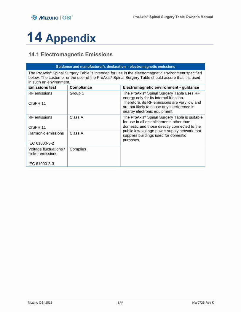
ProAxis® Spinal Surgery Table Owner’s Manual
136 Mizuho OSI 2016 NW0725 Rev K
14 Appendix
14.1 Electromagnetic Emissions
Guidance and manufacturer’s declaration – electromagnetic emissions
The ProAxis® Spinal Surgery Table is intended for use in the electromagnetic environment specified below. The customer or the user of the ProAxis® Spinal Surgery Table should assure that it is used in such an environment.
Emissions test Compliance Electromagnetic environment - guidance
RF emissions
CISPR 11
Group 1 The ProAxis® Spinal Surgery Table uses RF energy only for its internal function. Therefore, its RF emissions are very low and are not likely to cause any interference in nearby electronic equipment.
RF emissions
CISPR 11
Class A The ProAxis® Spinal Surgery Table is suitable for use in all establishments other than domestic and those directly connected to the public low-voltage power supply network that supplies buildings used for domestic purposes.
Harmonic emissions
IEC 61000-3-2
Class A
Voltage fluctuations / flicker emissions
IEC 61000-3-3
Complies
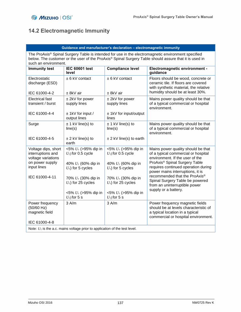
ProAxis® Spinal Surgery Table Owner’s Manual
137 Mizuho OSI 2016 NW0725 Rev K
14.2 Electromagnetic Immunity
Guidance and manufacturer’s declaration – electromagnetic immunity
The ProAxis® Spinal Surgery Table is intended for use in the electromagnetic environment specified below. The customer or the user of the ProAxis® Spinal Surgery Table should assure that it is used in such an environment.
Immunity test IEC 60601 test level
Compliance level Electromagnetic environment - guidance
Electrostatic discharge (ESD)
IEC 61000-4-2
± 6 kV contact
± 8kV air
± 6 kV contact
± 8kV air
Floors should be wood, concrete or ceramic tile. If floors are covered with synthetic material, the relative humidity should be at least 30%.
Electrical fast transient / burst
IEC 61000-4-4
± 2kV for power supply lines
± 1kV for input / output lines
± 2kV for power supply lines
± 1kV for input/output lines
Mains power quality should be that of a typical commercial or hospital environment.
Surge
IEC 61000-4-5
± 1 kV line(s) to line(s)
± 2 kV line(s) to earth
± 1 kV line(s) to line(s)
± 2 kV line(s) to earth
Mains power quality should be that of a typical commercial or hospital environment.
Voltage dips, short interruptions and voltage variations on power supply input lines
IEC 61000-4-11
<5% UT (>95% dip in UT) for 0.5 cycle
40% UT (60% dip in
UT) for 5 cycles
70% UT (30% dip in
UT) for 25 cycles
<5% UT (>95% dip in UT) for 5 s
<5% UT (>95% dip in UT) for 0.5 cycle
40% UT (60% dip in
UT) for 5 cycles
70% UT (30% dip in
UT) for 25 cycles
<5% UT (>95% dip in UT) for 5 s
Mains power quality should be that of a typical commercial or hospital environment. If the user of the ProAxis® Spinal Surgery Table requires continued operation during power mains interruptions, it is recommended that the ProAxis® Spinal Surgery Table be powered from an uninterruptible power supply or a battery.
Power frequency (50/60 Hz) magnetic field
IEC 61000-4-8
3 A/m 3 A/m Power frequency magnetic fields should be at levels characteristic of a typical location in a typical commercial or hospital environment.
Note: UT is the a.c. mains voltage prior to application of the test level.
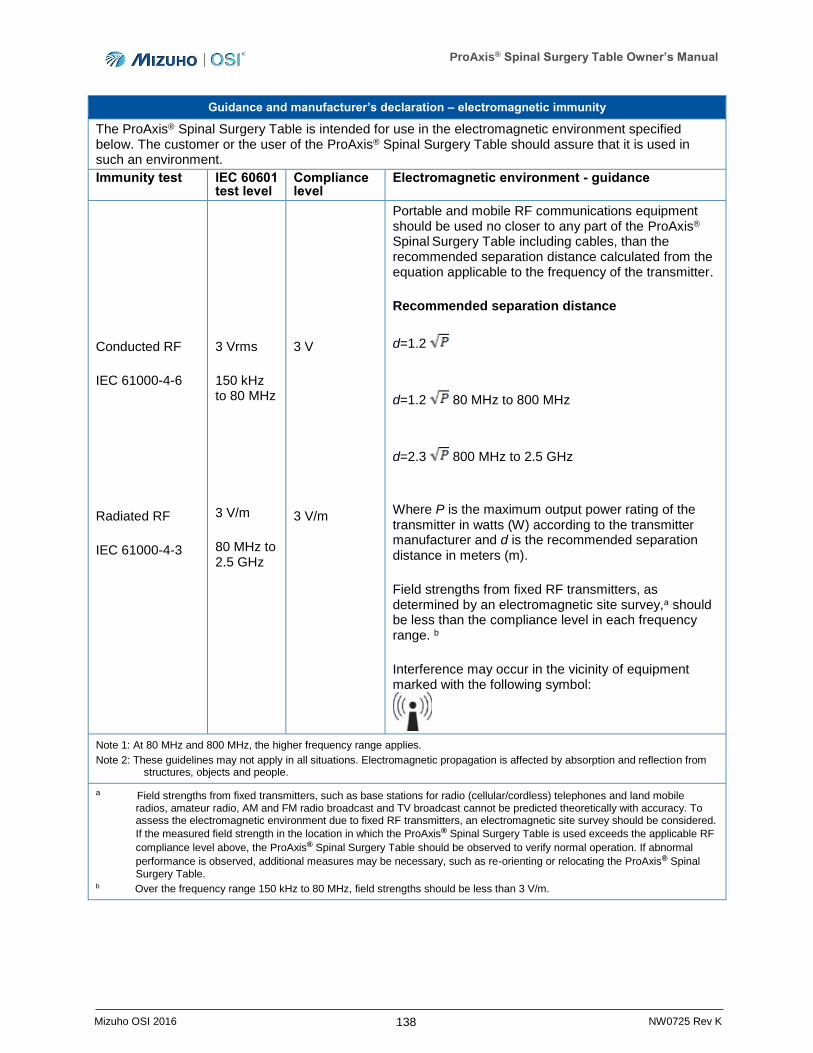
ProAxis® Spinal Surgery Table Owner’s Manual
138 Mizuho OSI 2016 NW0725 Rev K
Guidance and manufacturer’s declaration – electromagnetic immunity
The ProAxis® Spinal Surgery Table is intended for use in the electromagnetic environment specified below. The customer or the user of the ProAxis® Spinal Surgery Table should assure that it is used in such an environment.
Immunity test IEC 60601 test level
Compliance level
Electromagnetic environment - guidance
Conducted RF
IEC 61000-4-6
Radiated RF
IEC 61000-4-3
3 Vrms
150 kHz to 80 MHz
3 V/m
80 MHz to 2.5 GHz
3 V
3 V/m
Portable and mobile RF communications equipment should be used no closer to any part of the ProAxis® Spinal Surgery Table including cables, than the recommended separation distance calculated from the equation applicable to the frequency of the transmitter.
Recommended separation distance
d=1.2
d=1.2 80 MHz to 800 MHz
d=2.3 800 MHz to 2.5 GHz
Where P is the maximum output power rating of the transmitter in watts (W) according to the transmitter manufacturer and d is the recommended separation distance in meters (m).
Field strengths from fixed RF transmitters, as determined by an electromagnetic site survey,a should be less than the compliance level in each frequency range. b
Interference may occur in the vicinity of equipment marked with the following symbol:
Note 1: At 80 MHz and 800 MHz, the higher frequency range applies.
Note 2: These guidelines may not apply in all situations. Electromagnetic propagation is affected by absorption and reflection from structures, objects and people.
a Field strengths from fixed transmitters, such as base stations for radio (cellular/cordless) telephones and land mobile radios, amateur radio, AM and FM radio broadcast and TV broadcast cannot be predicted theoretically with accuracy. To assess the electromagnetic environment due to fixed RF transmitters, an electromagnetic site survey should be considered.
If the measured field strength in the location in which the ProAxis® Spinal Surgery Table is used exceeds the applicable RF
compliance level above, the ProAxis® Spinal Surgery Table should be observed to verify normal operation. If abnormal
performance is observed, additional measures may be necessary, such as re-orienting or relocating the ProAxis® Spinal
Surgery Table. b Over the frequency range 150 kHz to 80 MHz, field strengths should be less than 3 V/m.
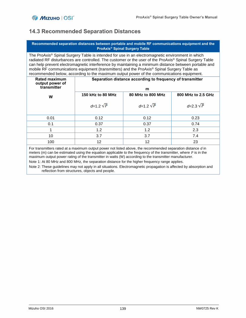
ProAxis® Spinal Surgery Table Owner’s Manual
139 Mizuho OSI 2016 NW0725 Rev K
14.3 Recommended Separation Distances
Recommended separation distances between portable and mobile RF communications equipment and the
ProAxis® Spinal Surgery Table
The ProAxis® Spinal Surgery Table is intended for use in an electromagnetic environment in which radiated RF disturbances are controlled. The customer or the user of the ProAxis® Spinal Surgery Table can help prevent electromagnetic interference by maintaining a minimum distance between portable and mobile RF communications equipment (transmitters) and the ProAxis® Spinal Surgery Table as recommended below, according to the maximum output power of the communications equipment.
Rated maximum output power of
transmitter
W
Separation distance according to frequency of transmitter
m
150 kHz to 80 MHz
d=1.2
80 MHz to 800 MHz
d=1.2
800 MHz to 2.5 GHz
d=2.3
0.01 0.12 0.12 0.23
0.1 0.37 0.37 0.74
1 1.2 1.2 2.3
10 3.7 3.7 7.4
100 12 12 23
For transmitters rated at a maximum output power not listed above, the recommended separation distance d in meters (m) can be estimated using the equation applicable to the frequency of the transmitter, where P is in the maximum output power rating of the transmitter in watts (W) according to the transmitter manufacturer.
Note 1: At 80 MHz and 800 MHz, the separation distance for the higher frequency range applies.
Note 2: These guidelines may not apply in all situations. Electromagnetic propagation is affected by absorption and reflection from structures, objects and people.