Pro Wireless Multimedia Kit - hdflow.com · ISSUED: 07-24-12 SHEET #: 180-9025-1 User Manual and...
36
ISSUED: 07-24-12 SHEET #: 180-9025-1 User Manual and Installation Guide Pro Wireless Multimedia Kit Models: HDS200-R HD Flow Pro Wireless Multimedia Receiver READY ®
-
Upload
vuongkhuong -
Category
Documents
-
view
215 -
download
0
Transcript of Pro Wireless Multimedia Kit - hdflow.com · ISSUED: 07-24-12 SHEET #: 180-9025-1 User Manual and...

ISSUED: 07-24-12 SHEET #: 180-9025-1
User Manual and Installation Guide
Pro Wireless Multimedia Kit
Models:HDS200-RHD Flow Pro WirelessMultimedia Receiver
READY
®

2 of 36 ISSUED: 07-24-12 SHEET #: 180-9025-1
ContentsSafety Precautions ..................................................................................................3
Proper Care and Safety ...........................................................................................3
Unit Care Recommendations .................................................................................3
Introduction ..............................................................................................................4
Features ................................................................................................................4
Package Contents .................................................................................................4
Product Specifi cations............................................................................................5
Video Format Supported .......................................................................................5
Audio Format Supported .......................................................................................5
Wireless Connection .............................................................................................5
Receiver ................................................................................................................6
Remote Control ...................................................................................................10
Multicast Programming ........................................................................................13
USB Multicast Setup Method ..............................................................................13
LAN Multicast Setup Method (Recommended) ...................................................13
Connecting your HD Flow Pro Wireless Transmitter or Receiver to the Computer ............................................................................................................................13
Transmitter Start-Up and Connection ..................................................................17
Transmitter Multicast Programming .....................................................................17
Receiver 1 LAN Programming .............................................................................20
Receivers 2+ Multicast Programming .................................................................22
Multicast Receiver 2, 3, and 4 Programming ......................................................23
Installation ..............................................................................................................26
Powering-up the HD Flow Pro Wireless Multimedia Receiver ............................27
Selecting Input and Output Port .........................................................................28
Indicator Lights Decoded .....................................................................................29
Appendix ................................................................................................................30
FCC Compliance .................................................................................................33
CE Compliance ...................................................................................................33
Warranty .................................................................................................................34
Contact Information ..............................................................................................35
3 of 36 ISSUED: 07-24-12 SHEET #: 180-9025-1
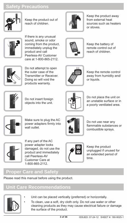
• Unit can be placed vertically (preferred) or horizontally.• To clean, use a soft, dry cloth only. Do not use water or other
cleaning products as they may cause electrical failure or damage the surface of the product.
Keep the product out of reach of children.
Keep the product away from external heat sources such as heaters or stoves.
If there is any unusual sound, smoke or odor coming from the product, immediately unplug the product and call Peerless-AV Customer care at 1-800-865-2112.
Keep the battery of remote control out of reach of children.
Do not attempt to open the outer case of the Transmitter or Receiver. Doing so will void the products warranty.
Keep the remote control away from humidity and/or liquids.
Do not insert foreign objects into the unit.
Do not place the unit on an unstable surface or in a poorly ventilated area.
Make sure to plug the AC power adapters fi rmly into wall outlet.
Do not use near any fl ammable substances or combustible sprays.
If any part of the AC power adapter looks damaged, do not use the product and immediately call Peerless-AV Customer Care at 1-800-865-2112.
Keep the product unplugged if unused for an extended period of time.
Safety Precautions
Please read this manual before using the product.
Proper Care and Safety
Unit Care Recommendations

4 of 36 ISSUED: 07-24-12 SHEET #: 180-9025-1
The HD Flow Pro Wireless Multimedia Receiver expands the peer-to-peer kit to a multicast system that allows transmitting to up to 4 displays.
Features• Low latency: ≤ 30ms.• Supports both digital (HDMI) and analog (Component, Composite) video/
audio.• Supports Wireless or Wired connection - IEEE 802.11n 5 GHz WiFi, LAN
connection.• Two internal antennas (supporting MIMO).• HDCP v1.1 compliant.• Supports both DTV & VESA standards: DTV: 1920x1080i60/p60,
1280x720p60, 720x480i60/p60, VESA: WSXGA+(1680x1050), SXGA(1280x1024), WXGA(1280x800), XGA(1024x768), SVGA(800x600), VGA(640x480).
• Supports passive 3D content.• Plug and play setup requires no software programming.
Package ContentsEnsure that the following items are present in the package. If any items are missing or damaged, please call Peerless-AV Customer Care at 1-800-865-2112(available 7:00am - 7:00pm CST Monday - Friday).
Remote ControlReceiver
Manual
Stand
AC Adapter
Introduction
User Manual and Installation Guide
Pro Wireless Multimedia Kit
Models:HDS200-R
®

5 of 36 ISSUED: 07-24-12 SHEET #: 180-9025-1
Product Specifi cations
1 x HDMI up to 1080p (60Hz)1 x Composite1 x YPbPr ComponentH.264 Baseline Profile with Level 4.2HDCP compliant
Wireless Connection Supporting IEEE 802.11n: OFDMRJ-45 LAN PortDirect Connection (LAN Cable)1 x LAN Port10/100 Base
USB 1 x USB Type A FemaleAudio Output 1 x 3.5mm Audio Jack, 1 Stereo RCA Audio JackVideo Resolution 480i/p, 720p, 1080i/p (24/30/60fps)Streaming Latency < 30msFrequency 5.15 - 5.25GHzLAN Connection 10/100 BaseRange 131ft (40m)Security 802.1x, 802.11i, WPA2, WPA and WEP 64/128 TKIP AES
2 x internal antenna MIMO Interface
IR Extender IR-ExtenderColor Black
Voltage: 12VDCAmps: 2AConsumption: 12V 2A
Antenna Type
Power
HDS200-RVideo Output
Encoding
Wire Connection
LAN
Video Format Supported• Digital Video
º HDMI - Up to 1080p @ 24Hz, 25Hz, 30Hz, 50Hz, 60Hz
• Analog Video º Composite – 480i @ 60Hz, 70Hz, 85Hz º Component – 1080i @ 50Hz, 60Hz, 720p @ 50Hz, 60Hz º VGA – Up to 1920x1080 @ 50Hz, 60Hz
Audio Format Supported• The Receiver outputs stereo audio.
Wireless Connection• The HD Flow Pro Wireless Multimedia Receiver is capable of receiving Full
HD 1080p media via a wireless connection or a wired connection from an HD Flow Pro Wireless Multimedia Transmitter.

6 of 36 ISSUED: 07-24-12 SHEET #: 180-9025-1
1
2
3
4
5
6
Receiver Front
Receiver

7 of 36 ISSUED: 07-24-12 SHEET #: 180-9025-1
Receiver Front
1. Power/Link • Blinking indicator light - System booting or establishing link between the Trans-
mitter and the Receiver.• Rapid blinking indicator light - Software upgrading or wireless/LAN mode switch-
ing.• Solid indicator light - Link between the Transmitter and Receiver has been estab-
lished and is ready for signal transmission.
2. HDMI• The HDMI indicator light will be illuminated when the HDMI port is selected for
video output. • If there is no signal, and/or the cable is not connected, the indicator light will
blink.
3. COMPO • The COMPO (component) indicator light will be illuminated when component
output is selected for video out.• If there is no signal, and/or the cable is not connected, the indicator light will
blink. 4. AV
• The AV Indicator light will be illuminated when the AV port (composite) is selected for the video output.
• If there is no signal, and/or the cable is not connected the indicator light will blink.
5. IR Window• IR receiving window enables remote control of components.
6. Power/Source Selection Button • Press and hold for 3 seconds to turn on the unit.• When powered on:
º Press to select the video input source. Each press of the button will cycle through the available video input "HDMI→ COMPO→ AV →HDMI" in sequence.
º Press and hold for 8 seconds to turn the unit off.

8 of 36 ISSUED: 07-24-12 SHEET #: 180-9025-1
1
2
3
4
5
6
7
8
Receiver Back
9 of 36 ISSUED: 07-24-12 SHEET #: 180-9025-1
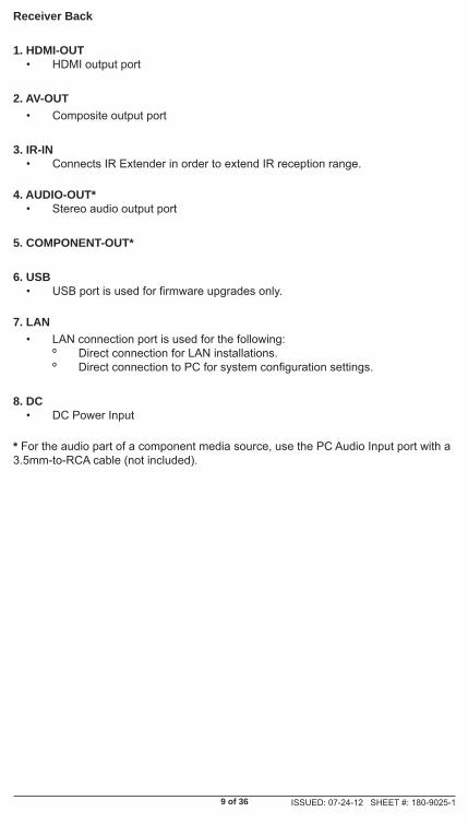
Receiver Back
1. HDMI-OUT• HDMI output port
2. AV-OUT• Composite output port
3. IR-IN • Connects IR Extender in order to extend IR reception range.
4. AUDIO-OUT*• Stereo audio output port
5. COMPONENT-OUT*
6. USB • USB port is used for fi rmware upgrades only.
7. LAN • LAN connection port is used for the following:
º Direct connection for LAN installations. º Direct connection to PC for system confi guration settings.
8. DC• DC Power Input
* For the audio part of a component media source, use the PC Audio Input port with a 3.5mm-to-RCA cable (not included).

10 of 36 ISSUED: 07-24-12 SHEET #: 180-9025-1
Remote Control
Remote Control Functions
1. POWER - Turns the Transmitter and Receiver power ON/OFF.
• ON: If the Transmitter and Receiver are powered off and the Power/Link Indicator Light is on, press the power button pointed at either unit to turn on both units at the same time (this will take about 30 seconds).
• ON: If the Transmitter and Receiver are powered off and the Power/Link Indicator Light is off, each unit will need to be turned on separately. Point the remote at each unit's IR Input Port and press the power button to turn on. (this will take about 1 minute and 30 seconds).
• OFF: If the Transmitter and Receiver are powered on and the Power/Link Indicator Light is on, press the power button to turn off both units at the same time to put the system in Standby mode. The Power/Link Indicator Light will remain on.
• OFF: If the Transmitter and Receiver are powered on and the Power/Link Indicator Light is on, press and hold the power button for 8 seconds. Both Transmitter and Receiver will be turned off at the same time. The Power/Link Indicator Light will turn off.
Note: If the Transmitter and Receiver are powered on with the Power/Link Indicator Light fl ashing, both units will need to be powered off individually.
1
3
45
2
6

11 of 36 ISSUED: 07-24-12 SHEET #: 180-9025-1
2. INFO* - Displays the following information on the screen for:
• Transmitter ** - WiFi Channel, Firmware Version, Audio/Video Input, and Source Resolution.
• Receiver - Connection, Firmware Version, Video Output, Display Resolution, WiFi Reception Strength 1/5 to 5/5 (where 1/5 is the weakest signal and 5/5 is the strongest signal).
* Displayed information will disappear automatically after 10 seconds.
** The Transmitter unit’s information will only be displayed if the connection between the Transmitter unit and Receiver has been established.
3. VIDEO OUT (Receiver) - Selects the AUDIO/VIDEO output port of the Receiver.
• HDMI - Selects HDMI as the AUDIO/VIDEO output.• Component - Selects Component as the AUDIO/VIDEO output.• AV - Selects AV as the AUDIO/VIDEO output..
Note: Remote must be pointing at the Receiver directly to control its output settings. This may also be accomplished without the use of the remote control by toggling between outputs via the Power/Source Selection button.
4. LAN* (Red) - Selects LAN (wired) mode.
5. WiFi CH1** (Green) - Selects WiFi (Wireless) mode, Ch1.
6. WiFi CH2** (Yellow) - Selects WiFi (Wireless) mode, Ch2.
* Your new Receiver is set to WiFi mode. To change to LAN mode, press and hold the LAN button for approximately 6 seconds or until the Link Indicator Light starts blinking.
** Your new Receiver is preset to WiFi Ch1. The channel setting on the new Receiver MUST match the channel setting in your current system confi guration. Make sure that the connection between the new Receiver and the Transmitter is not established. (noted by a fl ashing Link Indicator Light). To change WiFi channel, press and hold the desired WiFi channel button for approximately 6 seconds or until the Link Indicator Light starts blinking.
Notes:
• When you are pairing your new Receiver with your current HD Flow Pro Wireless Multimedia Kit the new Receiver MUST be on the same channel as your current kit.
• Only the unit that receives the IR signal will change WiFi frequencies. For proper operation both Receiver and Transmitter units need to be on the same WiFi channel.

12 of 36 ISSUED: 07-24-12 SHEET #: 180-9025-1
The battery slip is located on the back of the at the bottom of the remote.
Step 1
Push the tab, located on the left of the battery slip, to the right and pull out the slip.
Battery SlipBattery Slip Tab
Step 2
Place the battery into the slip, positive (+) end facing up as shown.
Step 3
Place the slip back into the remote to complete the installation.
Installing the Remote Control Battery

13 of 36 ISSUED: 07-24-12 SHEET #: 180-9025-1
USB Multicast Setup Method
USB Multicast Setup Method is available to set up the HD Flow Pro Wireless Multimedia Kit as a multicast system that transmits to 2, 3 or 4 Receivers. For USB Multicast Set-Up Method please visit http://www.hdfl ow.com/Tech-Support/ to view the instructional video.
LAN Multicast Setup Method (Recommended)
To set up the HD Flow Pro Wireless Multimedia Kit as a multicast system that transmits to 2, 3 or 4 Receivers using the LAN Confi guration Method, please fully read the instructions below before proceeding.
Note: Network settings may vary by location and menus based on the operating system that is being used. This guide is based on Windows 7.
Required Items:• RJ45 cable • Computer (laptop/desktop) • HD Flow Transmitter and Receiver(s)
Connecting your HD Flow Pro Wireless Transmitter or Receiver to the Computer
Setting up your Computer:
Step 1
Go to your start menu and click on the “Control Panel”.
Step 2
In the “Control Panel Window” fi nd and click on Network and Sharing Center.
Multicast Programming

14 of 36 ISSUED: 07-24-12 SHEET #: 180-9025-1
Step 3
Inside the Networking and Sharing Center window, click on Change Adapter Settings.
Step 4
In the Change Adapter Settings window right-click on Local Area Connection and click on Properties.
15 of 36 ISSUED: 07-24-12 SHEET #: 180-9025-1
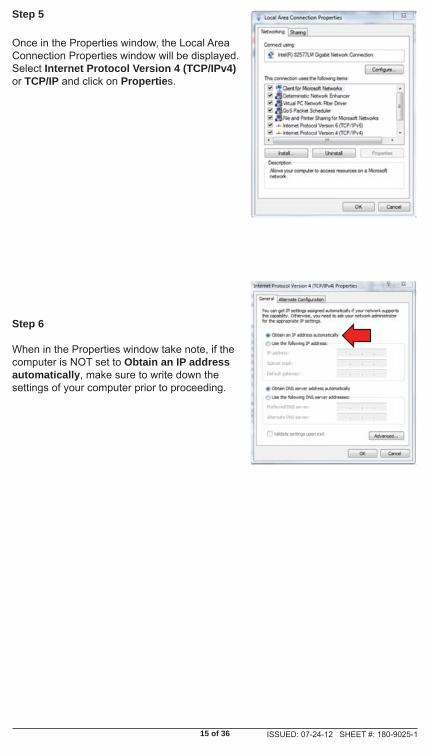
Step 5
Once in the Properties window, the Local Area Connection Properties window will be displayed. Select Internet Protocol Version 4 (TCP/IPv4) or TCP/IP and click on Properties.
Step 6
When in the Properties window take note, if the computer is NOT set to Obtain an IP address automatically, make sure to write down the settings of your computer prior to proceeding.
16 of 36 ISSUED: 07-24-12 SHEET #: 180-9025-1
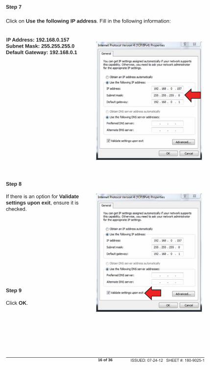
Step 7
Click on Use the following IP address. Fill in the following information:
IP Address: 192.168.0.157Subnet Mask: 255.255.255.0Default Gateway: 192.168.0.1
Step 8
If there is an option for Validate settings upon exit, ensure it is checked.
Step 9
Click OK.

17 of 36 ISSUED: 07-24-12 SHEET #: 180-9025-1
Your computer is now set up to communicate with the HD Flow Pro Wireless Multimedia Transmitter and Receiver.
Note: When programming is completed, you will need to return your network settings back to original.
Transmitter Start-Up and Connection
Step 1
Plug in The HD Flow Pro Wireless Multimedia Transmitter and ensure it has fully started up (top indicator light and one input indicator light will be blinking).
Step 2
Connect the RJ45 cable to the computer.
Step 3
Connect the other end of the RJ45 cable to the Transmitter or Receiver and follow the appropriate instruction below. Read the entire instruction below before proceeding.
Transmitter Multicast Programming
Step 1
Open your preferred browser.
Step 2
In the address bar of the browser type 192.168.0.151 and press enter.You will be taken to the programming site for the Transmitter.
Note: Transmitter Ethernet IP is always 192.168.0.151

18 of 36 ISSUED: 07-24-12 SHEET #: 180-9025-1
Step 3
The Transmitter, by default, is set to P2P, Unicast Mode. Click on the pull down menu next to Streaming Mode and select Multicast.
Notes:
• Do not change any other setting other than Streaming Mode.• Take note of the SSID of the Transmitter, it is case sensitive.
Step 4
Once all the settings have been entered, click the Submit button at the bottom of the form. Keep clicking on the Submit button until you see confi rmation "System confi gurations are changed", as below:

19 of 36 ISSUED: 07-24-12 SHEET #: 180-9025-1
Step 5
After submitting the information and receiving confi rmation, it is MANDATORY to click on Save Changes, located in the left-hand navigation bar, to ensure that your programming will be saved.
Step 6
Once clicking on Save Changes ,you will be prompted to save your system confi gurations. Confi rm that you would like to save them by clicking the Save button. You will be prompted again to make sure you want to save these changes. Confi rm that you would like to save them by clicking the Save button again.
Step 7
Unplug the RJ45 cable from the Transmitter. At this time the Transmitter can be unplugged from power as well.
Congratulations! You have completed programming of the Transmitterand are almost ready to run your multicast system.

20 of 36 ISSUED: 07-24-12 SHEET #: 180-9025-1
Receiver 1 LAN Programming
General Start Up and Connection Instructions
Step 1
Plug in The HD Flow Pro Wireless Multimedia Receiver and ensure it has fully started up (top indicator light and one output indicator light will be blinking).
Step 2
Connect the RJ45 cable to the computer.
Step 3
Connect the other end of the RJ45 cable to the Receiver.
Step 4
Open your preferred browser.
Step 5
In the address bar of the browser, type 192.168.0.152 and press enter.
Note: The new Receiver IP is always 192.168.0.152, unless the Receiver has been pre-programmed to work with your system.
Step 6
The Receiver, by default, is set to P2P, Unicast mode. Click on the pull-down menu next to Streaming Mode and select Multicast.
Note: The only changes that need to be made in the settings for the Receiver 1 are to ensure that Streaming Mode is set to WiFi and that the SSID matches EXACTLY the SSID of the Transmitter.

21 of 36 ISSUED: 07-24-12 SHEET #: 180-9025-1
Receiver 1 Settings should be as follows:
Ethernet IP: 192.168.0.152Ethernet NetMask: 255.255.255.0Gateway: 192.168.0.1Streaming Mode: Multicast (Second option in the drop down menu. Once you select Multicast you will be able to modify the WiFi RXID)WiFi RXID: Slave1WiFi SSID – ITRIO_XXXX (XXXX should be the SSID of the Transmitter, note the SSID is case sensitive).Group IP (multicast): 227.2.2.7Peer IP(LAN): 192.168.0.151
Step 7
Click the Submit button at the bottom of the form. Keep clicking on the Submit button until you see confi rmation "System confi gurations are changed", as below:
Step 8
After submitting the information and receiving confi rmation, it is MANDATORY to click on Save Changes, located in the left-hand navigation bar, to ensure that your programming will be saved.

22 of 36 ISSUED: 07-24-12 SHEET #: 180-9025-1
Step 9
Once clicking on Save Changes ,you will be prompted to save your system confi gurations. Confi rm that you would like to save them by clicking the Save button. You will be prompted again to make sure you want to save these changes. Confi rm that you would like to save them by clicking the Save button again.
Step 10
Unplug the RJ45 cable from the HD Flow Pro Wireless Multimedia Receiver 1. At this time Receiver 1 can be unplugged from power.
Congratulations! You have completed programming of the fi rst Receiver and are ready to move to the next Receiver.
Receivers 2+ Multicast Programming
Multicast Receiver 2, 3 and 4 Settings Overview
Follow the steps 1-8 from Receiver 1 programming using the below corresponding Receiver settings. During Step 6, reference multicast programming instructions for Receivers 2, 3 and 4 below. After Step 6 follow Multicast Receiver 2, 3, and 4 Programming Instructions below.
Multicast Receiver 2 Settings -- should be as follows:
Ethernet IP: 192.168.0.153Ethernet NetMask: 255.255.255.0Gateway: 192.168.0.1Streaming Mode: Multicast (Second option in the drop down menu. Once you select Multicast you will be able to modify the WiFi RXID)WiFi RXID: Slave2WiFi SSID – ITRIO_XXXX (XXXX should be the SSID of the Transmitter, note the SSID is case sensitive.)Group IP (multicast): 227.2.2.7Peer IP(LAN): 192.168.0.151

23 of 36 ISSUED: 07-24-12 SHEET #: 180-9025-1
Multicast Receiver 3 Settings --should be as follows: Ethernet IP: 192.168.0.154Ethernet NetMask: 255.255.255.0Gateway: 192.168.0.1Streaming Mode: Multicast (Second option in the drop down menu. Once you select Multicast you will be able to modify the WiFi RXID)WiFi RXID: Slave3WiFi SSID – ITRIO_XXXX (XXXX should be the SSID of the Transmitter, note the SSID is case sensitive.)Group IP (multicast): 227.2.2.7Peer IP(LAN): 192.168.0.151
Multicast Receiver 4 Settings -- should be as follows: Ethernet IP: 192.168.0.155Ethernet NetMask: 255.255.255.0Gateway: 192.168.0.1Streaming Mode: Multicast (Second option in the drop down menu. Once you select Multicast you will be able to modify the WiFi RXID)WiFi RXID: Slave4WiFi SSID – ITRIO_XXXX (XXXX should be the SSID of the Transmitter, note the SSID is case sensitive.)Group IP (multicast): 227.2.2.7Peer IP(LAN): 192.168.0.151
Multicast Receiver 2, 3, and 4 Programming
Step 1
When Submit is clicked in step 7, you will NOT see the confi rmation message. At this time you are no longer connected with the HD Flow Pro Wireless Reciever due to the modifi cation of the IP address from 192.168.0.152 to 192.168.0.153 for Receiver 2, 192.168.0.152 to 192.168.0.154 for Receiver 3, 192.168.0.152 to 192.168.0.155 for Receiver 4.
Step 2
In same browser window type in the new IP address 192.168.0.153 in the URL and you will be reconnected with the HD Flow Pro Wireless Multimedia Receiver 2. (see image below)
24 of 36 ISSUED: 07-24-12 SHEET #: 180-9025-1
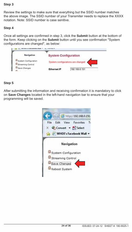
Step 3
Review the settings to make sure that everything but the SSID number matches the above image. The SSID number of your Transmiter needs to replace the XXXX notation. Note: SSID number is case senitive.
Step 4
Once all settings are confi rmed in step 3, click the Submit button at the bottom of the form. Keep clicking on the Submit button until you see confi rmation "System confi gurations are changed", as below:
Step 5
After submitting the information and receiving confi rmation it is mandatory to click on Save Changes located in the left-hand navigation bar to ensure that your programming will be saved.

25 of 36 ISSUED: 07-24-12 SHEET #: 180-9025-1
Step 6
Once clicking on Save Changes ,you will be prompted to save your system confi gurations. Confi rm that you would like to save them by clicking the Save button. You will be prompted again to make sure you want to save these changes. Confi rm that you would like to save them by clicking the Save button again.
Step 7
Unplug the RJ45 cable from the Receiver. At this time the Receiver can be unplugged from power. To set up remainder of the Receivers repeat Receivers 2+ Multicast Programming Instructions using the provided Receiver settings.
Congratulations! You have completed programming of this Receiver and are ready to move to the next Receiver if needed.
Note:When programming brand new units straight out of the box, the default IP to be entered into your browser will be 192.168.0.152. If reprogramming already pre-programmed units, please reference the IP address on the unit. If any multicast unit is reset to factory defaults, it will revert back to the 192.168.0.152 IP address regardless of the IP address label on the unit.
Caution:It is very important that the IP address is recorded for each unit. If IP addresses do not match any of the default addresses, unit(s) will need to be reset to default settings to regain access to LAN programming capabilities.

26 of 36 ISSUED: 07-24-12 SHEET #: 180-9025-1
InstallationStep 1
Connecting the Receiver to the Display Device
Note: Connect the Receiver to the display device using the port with the high resolution capability, HDMI port is preferred. Regardless of the number of analog or digital sources connected to the Transmitter, only one port is required to be connected to the display. Be sure the source resolution matches with the display device's resolution capabilities.
A. HDMI Output to Display
• Connect the HDMI cable from the Receiver's HDMI output to the display device's HDMI input.
B. Composite Output to Display
• Connect the composite RCA cable from the Receiver's AV output to the display device's composite input.
C. Component Output to Display
• Video - Connect the component video (YPbPr) cable from the Receiver's COMPONENT-OUT to the displays device's component input.
• Audio - A 3.5mm-to-RCA stereo audio cable is required (not included) to transmit audio when using this input. Connect the 3.5mm end of the cable to the Receiver's AUDIO-OUT port, then connect the RCA side of the cable to the RCA ports on the display decive.

27 of 36 ISSUED: 07-24-12 SHEET #: 180-9025-1
A. Plug-in the power adapter for the Receiver to an available power outlet.
B. Plug in the other end of the power cable to the Receiver . The unit will automatically turn on.
Step 3
Turn on your display device (TV, monitor, projector, etc.).
Note: All of the unplugged HD Flow Pro Wireless Multimedia Kit units should have been plugged in and connected to their respective display and source devices.
Step 4
While turning on the display device, the Transmitter and Receiver will be going through the start up process. The process takes about 1 to 2 minutes to complete. The Power/Link Indicator Light on the Transmitter and the Receiver should be fl ashing at fi rst. Flashing indicates that the Transmitter and Receiver are establishing a secure connection. Please wait until the connection is successfully established, indicated by the solid Power/Link Indicator Light.
Step 5
Select the output that the Receiver is connected to the display device with. At this time the output Indicator Light will become solid and the HD Flow logo will appear on the display device.
Step 6
Turn on the desired media source device that is connected to the Transmitter.
Step 7
Select the desired media source device input on the Transmitter.
Step 8
Play the source device media content and enjoy up to a Full HD 1080p wireless entertainment experience.
Powering-up the HD Flow Pro Wireless Multimedia Receiver
Step 2
28 of 36 ISSUED: 07-24-12 SHEET #: 180-9025-1
Tips
If the Transmitter and Receiver are not establishing a connection:
a. Ensure that both the Transmitter and Receiver are on the same WiFi channel
b. If the Transmitter and Receiver are not connecting after trying (a), it is recommended to verify the programming setting of the Receiver that is not establishing connection.
c. If two (2) or more Receivers are not connecting to the Transmitter, it is recommended to verify the Transmitters programmed settings
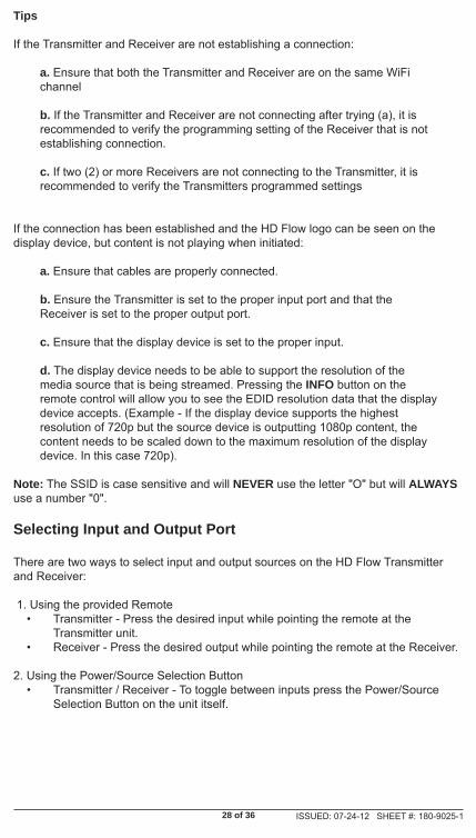
If the connection has been established and the HD Flow logo can be seen on the display device, but content is not playing when initiated:
a. Ensure that cables are properly connected.
b. Ensure the Transmitter is set to the proper input port and that the Receiver is set to the proper output port.
c. Ensure that the display device is set to the proper input.
d. The display device needs to be able to support the resolution of the media source that is being streamed. Pressing the INFO button on the remote control will allow you to see the EDID resolution data that the display device accepts. (Example - If the display device supports the highest resolution of 720p but the source device is outputting 1080p content, the content needs to be scaled down to the maximum resolution of the display device. In this case 720p).
Note: The SSID is case sensitive and will NEVER use the letter "O" but will ALWAYS use a number "0".
Selecting Input and Output Port
There are two ways to select input and output sources on the HD Flow Transmitter and Receiver:
1. Using the provided Remote• Transmitter - Press the desired input while pointing the remote at the
Transmitter unit.• Receiver - Press the desired output while pointing the remote at the Receiver.
2. Using the Power/Source Selection Button • Transmitter / Receiver - To toggle between inputs press the Power/Source
Selection Button on the unit itself.

29 of 36 ISSUED: 07-24-12 SHEET #: 180-9025-1
Notes: 1. Audio and video sources will switch simultaneously whether using the remote
or Power/Source Selection Button.2. Independent audio switching is only allowed for AV and PC audio.3. Inputs on the Transmitter and Receiver can be switched by pointing the
remote at the Transmitter or Receiver ONLY if the connection between Transmitter and Receiver has been established, Link Indicator Light on.If the connection between Transmitter and Receiver has not been established, the inputs need to be selected at the location of each unit using either of the
above input and output selection methods.
Indicator Lights Decoded
Receiver
• Power/Link Indicator Light º Rapid Flashing – Switching from Wireless to LAN or from LAN to
Wireless connection or performing fi rmware update. º Flashing – Units are booting and establishing a secure connection for AV
transfer. º Solid – Successful connection has been established between Transmitter
and Receiver.
• HDMI, COMPO, AV - The Indicator Light will be solid for the selected port as long as output cable is present and connected to the output device. If no output device is connected to the selected output port, the Indicator Light will be fl ashing.

30 of 36 ISSUED: 07-24-12 SHEET #: 180-9025-1
Factory Reset
CAUTIONFactory reset will revert all settings to factory defaults. It is not recommended to perform factory reset on multicast systems (systems that have two or more Receivers). If there are issues with multicast system please reference http://www.hdfl ow.com/Tech-Support or call Technical Support at 1-800-865-2112.
Step 1
Unplug the Receiver from its power source.
Step 2
Press and hold the Power/Source Selection button on the front panel. While pressing the Power/Source Selection button on the front panel, plug in the DC power back into the unit being reset.
Step 3
Keep holding the Power/Source Selection button until the Indicator Lights on the Receiver are fl ashing rapidly, approximately 7 seconds.
Step 4
Release the front panel push button and wait for the unit to reset to factory defaults.
Please visit http://www.hdfl ow.com/Tech-Support/ to view factory reset training video.
Firmware Upgrade
Visit http://www.hdfl ow.com/Tech-Support/ for Peer-to-Peer and Multicast fi rmware upgrade instruction videos, fi le downloads and unit confi guration.
Notes:• HD Flow Pro Wireless Multimedia Kit, Peer-to-Peer units and Multicast
units have been pre-confi gured with the same version of fi rmware. When purchasing additional Receiver(s) it is recommended to check the fi rmware version.
• Firmware update should only be done when units are functioning properly. • During the update, DO NOT TURN THE UNIT OFF OR UNPLUG ITS POWER
SOURCE. Doing so will cause the unit to no longer function properly.• During the update process the display device will not show content.• Only when the unit(s) have fi nished updating and rebooted should the USB
dongle be removed.
Appendix

31 of 36 ISSUED: 07-24-12 SHEET #: 180-9025-1
How to Check Firmware VersionStep 1
Connect the Receiver that needs its fi rmware to be checked to the display device (reference the installation section of this manual).
Step 2
Plug in the power AC adapter into a power outlet, and then connect the power cord to the HD Flow Pro Wireless Multimedia Kit and turn on the display device.
Step 3
The start-up process of the HD Flow Pro Wireless Multimedia Kit takes about 1.5 to 2 minutes to complete. The Power/Link Indicator Light on the Transmitter and the Receiver should be fl ashing at fi rst. Flashing indicates that that the units are establishing a secure connection. Wait until the connection is successfully established, indicated by the Power/Link Indicator Light becoming a solid light.
Step 4
At this time the HD Flow logo should appear on your display device.
Note: If the logo does not appear, check to ensure that the proper input is selected on the Receiver and the display device.
Step 5
• Using the provided remote control, point the remote control directly into the IR window of the Receiver that is being checked for fi rmware version and press the “INFO” button. The below information should show up on the display device.
• Reference the example below on how to fi nd the fi rmware version for the Transmitter and Receiver.
Transmitter Designation
Receiver Designation
Firmware Version
Firmware Version

32 of 36 ISSUED: 07-24-12 SHEET #: 180-9025-1
HDMI D Sub AV(CVBS) HDMI COMP AV(CVBS)O O X O X XO O X O X XO O X O X XO O X O X XO O X O X XO O X O X XO O X O ^ XO O X O X XO O X O X XO O X O ^ XO O X O X XO O X O X XO O X O X XO O X O ^ XO O X O X XO O X O X XO O X O ^ XO O X O X XO X X O X XO O X O ^ XO X X O X XO O X O X XO O O X O OO O O X O OO O X O O XO O X O O XO O X O O XO O X O O XO O X O O OO O X O O OO O X O X XO X X O X XO X X O X XO O X O X XO O X O X X
1920 x 1080p301920 x 1080p501920 x 1080p60
1280 x 720p501280 x 720p601920 x 1080i501920 x 1080i601920 x 1080p241920 x 1080p25
1360 x 768p601440 x 900p60
1600 x 1200Rp601
1600 x 900p601680 x 1050p60
DTVFormat
(TV standard)
720 x 480I60(NTSC)720 x 576I50(PAL)720 x 480p60720 x 576p50
1152 x 864p851280 x 800p601280 x 960p601280 x 960p701280 x 960p851280 x 1024p60
800 x 600p851024 x 768p601024 x 768p701024 x 768p851152 x 864p601152 x 864p70
Video Standard ResolutionHD Flow Transmitter HD Flow Receiver
VESAFormat
(PC standard)
640 x 480p60640 x 480p70640 x 480p85800 x 600p60800 x 600p70
O - Compatable X - Not Compatable ^ - Compatibility varys based on output device setings
Notes:
1. 1600 x 1200p60 is a reduced format.2. HD Flow simply relays the input format of the video from the Transmitter to the
Receiver. HD Flow does not change the video format. If you want to change output format, you should change input format on the external device which is connected to the Transmitter.
3. When transmitting NTSC:480i or PAL:576i from the Transmitter, COMPONENT-OUT MUST be used at the Receiver.
4. Only HDMI 480i resolution input will provide composite AV-OUT signal at the Receiver. For all other resolutions, use HDMI-OUT or COMPONENT-OUT at the Receiver.
5. PC-IN fully supports resolutions noted above ONLY when HDMI-OUT is used at the Receiver.
Supported Video Formats
33 of 36 ISSUED: 07-24-12 SHEET #: 180-9025-1
FCC Compliance
This equipment has been tested and found to comply with the limits for a Class B digital device, pursuant to part 15 of the FCC Rules. These limits are designed to provide reasonable protection against harmful interference in a residential installation. This equipment generates, uses, and can radiate radio frequency energy and, if not installed and used in accordance with the instruction manual, may cause harmful interference to radio communications. However there is no guarantee that interference will not occur in a particular installation. If this equipment does cause harmful interference to radio or television reception, which can be determined by turning the equipment off and on, the user is encouraged to try to:
1. Relocate the receiving antenna.
2. Increase the separation between equipment and Receiver.
3. Connect the equipment into an outlet on a circuit different from that to which the Receiver is connected.
4. Consult the dealer or an experienced radio/TV technician for help.
CE Compliance
This device has been tested and found to comply with the following European Union directives: Electromagnetic Capability (89/336/EMC), Low Voltage (73/23/EEC) and R&TTED (1999/5/EC).

34 of 36 ISSUED: 07-24-12 SHEET #: 180-9025-1
1 YEAR LIMITED WARRANTYThe HDS200 is distributed by Peerless Industries, Inc. using the highest quality components andtechnology available. The Product is warranted to be free from defects in material and workmanship,given normal use and care, for 1 Year from the original purchase date with proof of purchase. Pleaseretain a copy of your receipt as you will need this to obtain warranty work. We will repair or replacethe product which fails as a result of such a defect during the warranty period. The accessories are notcovered by this warranty.
This warranty is the customers’ exclusive remedy for product defect and does not apply to:
• Any modifi cations made to the product in any way by the customer• Attachments to the product by the customer that causes product damage• Any product which the seals/and or serial numbers and/or logos have been
broken, removed,• or tampered with, defaced, or altered in any manner• Damage caused by abuse, misuse, accident, water, or theft• Physical damage• Loss of the Accessories
Except as stated above, Peerless Industries, Inc. makes no express or implied warranties as to any product, in Particular, makes no warranty of merchantability or tness for any particular purpose. Peerless Industries, Inc. shall not be liable for consequential or incidental damages arising from any product defect. Our liability is limited to replacement of any defective product as stipulated under the warranty conditions. Peerless Industries, Inc. expressly disclaims all warranties not satised in this limited warranty. Any implied warranties that may be imposed by law are limited to the terms of this limited warranty.
Warranty

35 of 36 ISSUED: 07-24-12 SHEET #: 180-9025-1
Contact Information
Customer Care
Need help with installation or set up? Call Peerless-AV Customer Care 1-1-800-865-2112 (available 7:00am- 7:00pm CST, Monday - Friday), or email us at
Peerless -AV2300 White Oak CircleAurora, IL 60502 USA
www.hdfl ow.com

Distributed exclusively by Peerless Industries, Inc.
2300 White Oak Circle, Aurora, IL 60502 USA
1-800-865-2112www.peerless-av.com
www.hdfl ow.com
©2012 Peerless-AV. All rights reserved. Peerless-AV is a trademark of Peerless Industries, Inc. HD Flow is a trademark of I Do It, LTD. Other parties’ marks are the property of their
respective owners.