PRO-TEK SUPERNOVA2 CHUCK
41
1 OPERATION MANUA L PRO-TEK SUPERNOVA2 CHUCK Date: 21 September 2020 Models: 23262 – Insert Thread (Insert Required) 23261 – M33 ASR Eurolock
Transcript of PRO-TEK SUPERNOVA2 CHUCK
1
O
PERATION
MAN
UA L
PRO-TEK SUPERNOVA2 CHUCK
Date: 21 September 2020
Models: 23262 – Insert Thread (Insert Required) 23261 – M33 ASR Eurolock

2
Contact Us
Teknatool International Ltd Phone: (+64) 9 477 5600
Teknatool USA Phone: 727-954-3433
Customer Solutions For all worldwide Inquiries, Repairs or Services (issues must be in writing)
Email: [email protected]
Or you can contact your retailer, for the contact details please see our website www.teknatool.com

3
Table of Contents
Contact Us ......................................................................................................................................................................... 2
Table of Contents .............................................................................................................................................................. 3
Welcome ........................................................................................................................................................................... 4
Benefits of NOVA PRO-TEK SUPERNOVA2 Chuck .......................................................................................................... 4
General Health and Safety Guidance ................................................................................................................................ 6
PRO-TEK SUPERNOVA2 Chuck – Types .............................................................................................................................. 9
NOVA Chuck Inserts ........................................................................................................................................................ 10
PRO-TEK SUPERNOVA2 Chuck Parts View ....................................................................................................................... 11
Operation of the chuck ................................................................................................................................................... 13
Mounting the jaws onto the chuck ................................................................................................................................. 13
Removing jaws from the chuck ....................................................................................................................................... 14
Mounting the chuck onto a lathe ................................................................................................................................... 15
Mounting the chuck using the ASR Eurolock locking ring ............................................................................................... 17
Screw chuck – Safe Lock Woodworm Screw ................................................................................................................... 18
To use the Safe Lock Woodworm screw on a workpiece ............................................................................................... 19
Forming a Mortis/Recess or Tenon/Spigot ..................................................................................................................... 20
Safety Concerns when turning ................................................................................................................................ 20
Forming a Mortis/Recess ............................................................................................................................................ 21
If You do not own a NOVA Dovetail Chisel ............................................................................................................. 21
Recommended Diameter of the recess .................................................................................................................. 22
Forming a Tenon/Spigot ............................................................................................................................................. 24
Recommended diameter for the tenon/spigot ...................................................................................................... 25
Troubleshooting .............................................................................................................................................................. 26
Chuck runout inspection procedure ............................................................................................................................... 28
Equipment Required ............................................................................................................................................... 28
Inspection procedure .............................................................................................................................................. 29
PRO TEK SUPERNOVA2 Chuck Maintenance ................................................................................................................... 33
Required tools ............................................................................................................................................................. 33
Removing the chuck from the lathe............................................................................................................................ 34
Disassembling the PRO-TEK SUPERNOVA2 chuck ....................................................................................................... 35
Parts to clean and inspect on the disassembled chuck .............................................................................................. 37
Reassembly of the SUPERNOVA2 Pro-Tek chuck ......................................................................................................... 37
Go to Teknatool.com to learn more about our full assortment of accessories .............................................................. 41

4
Welcome Thank you for purchasing our NOVA PRO-TEK SUPERNOVA2 geared chuck. It is a new addition to our NOVA woodturning chuck range with advanced features to enhance your chuck use. It provides a versatile and easy method for fast and secure work holding for all face turning – bowls, platters, egg cups, vases, boxes, goblets, and an endless variety of similar projects. The NOVA PRO-TEK SUPERNOVA2 Chuck combines the best features of our NOVA Chuck, SUPERNOVA Chucks, and similar woodturning chucks (wide jaw movement, quick two-way grip) with the advantages of the latest technology and inNOVAtion from Teknatool. As a valued customer, we would be pleased to hear from you and how you found your PRO-TEK SUPERNOVA2 Chuck. Any comments on the chuck or accessory ideas would be very welcome so that we can continue to offer what we believe is the best woodturning chucking system available.
Benefits of NOVA PRO-TEK SUPERNOVA2 Chuck
• Premium rust-resistant nickel-plated body for longer protection and less maintenance.
• Stronger and more versatile 50mm/2” PRO-TEK Jaws with an improved dovetail AND serrated profile for maximum control. The unique woodworking dovetail profile pulls the project into the chuck and holds round and square blanks more firmly.
• Upgraded 6-point star fasteners exerting more torque with ease, offering better holding power and minimizing strip out for longer life.
• New Star T-Bar Handle for easy grip and quicker tightening of screws. • Precision laser etched jaw numbering allowing ease of jaw and slide alignment,
positioning and change out. • CNC precision machined for unparalleled tolerances and accuracy. • Powerful Geared Grip delivers tremendous holding power. • Copper-infused, precision-cast jaw slides for effortless movement and
resistance to wear and tear. • Single-handed operation offers fast and convenient mounting for your project:
quicker setup equals more time to turn. • Intuitive clockwise scroll rotation for ease of use. • Auto Safety Stop Feature to keep Jaw slides from protruding past the chuck
body.
5
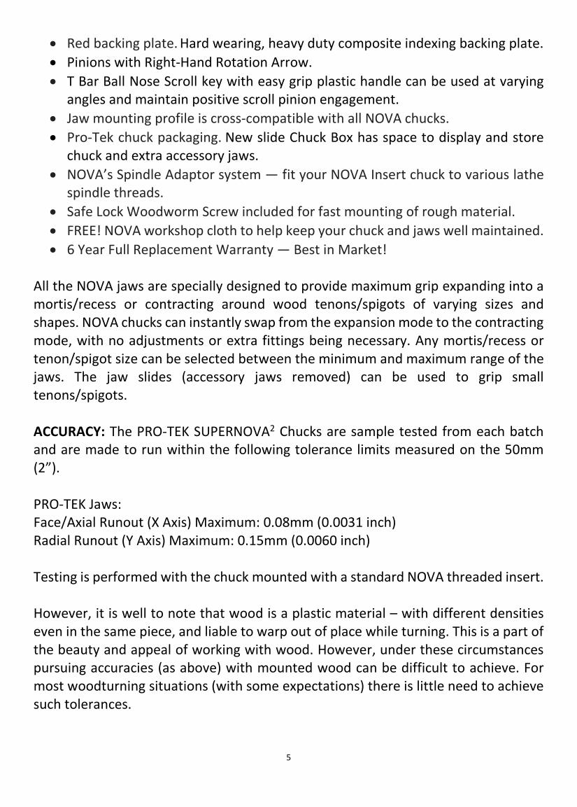
• Red backing plate. Hard wearing, heavy duty composite indexing backing plate. • Pinions with Right-Hand Rotation Arrow. • T Bar Ball Nose Scroll key with easy grip plastic handle can be used at varying
angles and maintain positive scroll pinion engagement. • Jaw mounting profile is cross-compatible with all NOVA chucks. • Pro-Tek chuck packaging. New slide Chuck Box has space to display and store
chuck and extra accessory jaws. • NOVA’s Spindle Adaptor system — fit your NOVA Insert chuck to various lathe
spindle threads. • Safe Lock Woodworm Screw included for fast mounting of rough material. • FREE! NOVA workshop cloth to help keep your chuck and jaws well maintained. • 6 Year Full Replacement Warranty — Best in Market!
All the NOVA jaws are specially designed to provide maximum grip expanding into a mortis/recess or contracting around wood tenons/spigots of varying sizes and shapes. NOVA chucks can instantly swap from the expansion mode to the contracting mode, with no adjustments or extra fittings being necessary. Any mortis/recess or tenon/spigot size can be selected between the minimum and maximum range of the jaws. The jaw slides (accessory jaws removed) can be used to grip small tenons/spigots. ACCURACY: The PRO-TEK SUPERNOVA2 Chucks are sample tested from each batch and are made to run within the following tolerance limits measured on the 50mm (2”). PRO-TEK Jaws: Face/Axial Runout (X Axis) Maximum: 0.08mm (0.0031 inch) Radial Runout (Y Axis) Maximum: 0.15mm (0.0060 inch) Testing is performed with the chuck mounted with a standard NOVA threaded insert. However, it is well to note that wood is a plastic material – with different densities even in the same piece, and liable to warp out of place while turning. This is a part of the beauty and appeal of working with wood. However, under these circumstances pursuing accuracies (as above) with mounted wood can be difficult to achieve. For most woodturning situations (with some expectations) there is little need to achieve such tolerances.

6
General Health and Safety Guidance ATTENTION: Please carefully read and understand the instructions in this manual before assembly, installation and use of your PRO-TEK SUPERNOVA2 Chuck.
Keep these instructions in a safe place for future reference. WARNING: This chuck can contribute to serious injury (as with any other power tool accessory) if this manual guidance is not followed or if it is used improperly on the lathe. Read and understand the lathe owner's manual. If you do not have a manual, contact the supplier of your lathe to obtain one before using the lathe and chuck. User must be professionally trained to use this chuck. Vocational school courses or other expert tuition is recommended. NOVA also recommends joining a woodturning club. As with other work holding methods, an extremely cautious and sensible approach is necessary. With the PRO-TEK SUPERNOVA2 chuck it is not possible to give exact directions as to the amount of tightening pressure required for adequate work holding or approved chisel cutting techniques. Follow closely strict guidelines in this manual for different jaw types on wood blank diameters and length, plus strictly follow recommended lathe speeds. Safe Operation: Eye Protection: Woodturning operations can result in objects being thrown into your eyes which can result in severe eye damage. Protective eye wear must always be used. Everyday spectacles are not protective eye wear. We recommend a full-face shield. Always wear eye protection which complies with current ANSI Standard Z87 (USA) Noise Protection: Use ear plugs or ear defenders. Particularly if the noise exceeds 85dB. Exposure to high levels of noise can lead to hearing problems. Dust Protection: Use respiratory protective equipment (dust mask, portable respirator device). Exposure to high levels of irritating dust when turning or sanding hardwoods, soft woods and manufactured composite boards (MDF) can result in serious health problems. In addition, adequate workshop dust extraction must be used. Chuck is properly secured on lathe spindle: Follow mounting instructions for your lathe for faceplates and other spindle fixtures. Do not rotate chuck under power

7
unless workpiece is firmly clamped. WARNING LATHE SPEED: Excessive speed is a serious lathe hazard. Always turn at the slowest speed possible. Speed will vary with wood blank size. The larger the blank the slower the speed. Consult your lathe manual or lathe information plate for speed guidelines. Do not attempt to use the chuck unless the recommended lathe speeds to size of wood blank are known. In addition, you must strictly follow the maximum speed limits set out in the operating section of this manual. Do not exceed them under any circumstances. CHECK WORKPIECE: Examine wood blank carefully before mounting on chuck/lathe. Only mount wood that has no cracks, splits, holes, or weaknesses (e.g. rotten or spongy sections). Do not use poorly jointed or laminated wood. Irregular or out of balance stock needs to be turned at the slowest possible speed until it is in balance. Make sure wood is clamped firmly. Follow mounting instructions for different gripping modes and jaw types. In the expansion mode do not use undue force or jaws may split the wood. As above Do not exceed maximum guidelines in this manual for wood blank diameters/length set out in this manual for different modes and jaw types. Check wood is securely held in chuck before operation. Check grip by vigorously wrenching wood blank back and forth. If any loosening occurs, re-examine holding area for adequate grip (Following mounting guidelines) and any damage to holding area. Rotate manually to make sure of clearance before switching power on. DUPLICATOR OR JIGS: Do not use chuck for work holding with a duplicator or jigs. Safe Practice: CHISEL USE: Use only handheld woodturning chisels to shape wood being held in chuck. Use the recommended chisel for the job. Use safe and commonly approved techniques. WARNING: Never attempt to place hands on a moving chuck on a lathe. Wait for the chuck to come to a complete stop before hands are anywhere near the chuck. Trying to grab at a moving chuck could result in SERIOUS INJURY. JAW SLIDES: For safe operation do not extend the jaw slides beyond the chuck body under any circumstances. Wherever possible stand to one side of the revolving wood.

8
WEAR SUITABLE CLOTHING. Do not wear any loose clothing, neck ties, gloves, bracelets, rings, or other jewelry that could get caught in moving parts. Wear protective hair covering to contain long hair. DRUGS, ALCOHOL, MEDICATION. Do not operate chuck or lathe while under the influence of drugs, alcohol, or any medication. KEEP CHILDREN AND VISITORS AWAY: All children and visitors should be kept safe distance from the work area. Make workshop childproof with padlocks, master switches, or by removing starter keys, or have machines fitted with a Striatech drive system using the password lock feature
9
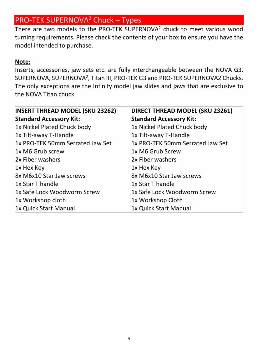
PRO-TEK SUPERNOVA2 Chuck – Types There are two models to the PRO-TEK SUPERNOVA2 chuck to meet various wood turning requirements. Please check the contents of your box to ensure you have the model intended to purchase. Note: Inserts, accessories, jaw sets etc. are fully interchangeable between the NOVA G3, SUPERNOVA, SUPERNOVA2, Titan III, PRO-TEK G3 and PRO-TEK SUPERNOVA2 Chucks. The only exceptions are the Infinity model jaw slides and jaws that are exclusive to the NOVA Titan chuck. INSERT THREAD MODEL (SKU 23262) Standard Accessory Kit: 1x Nickel Plated Chuck body 1x Tilt-away T-Handle 1x PRO-TEK 50mm Serrated Jaw Set 1x M6 Grub screw 2x Fiber washers 1x Hex Key 8x M6x10 Star Jaw screws 1x Star T handle 1x Safe Lock Woodworm Screw 1x Workshop cloth 1x Quick Start Manual
DIRECT THREAD MODEL (SKU 23261) Standard Accessory Kit: 1x Nickel Plated Chuck body 1x Tilt-away T-Handle 1x PRO-TEK 50mm Serrated Jaw Set 1x M6 Grub Screw 2x Fiber washers 1x Hex Key 8x M6x10 Star Jaw screws 1x Star T handle 1x Safe Lock Woodworm Screw 1x Workshop Cloth 1x Quick Start Manual
10
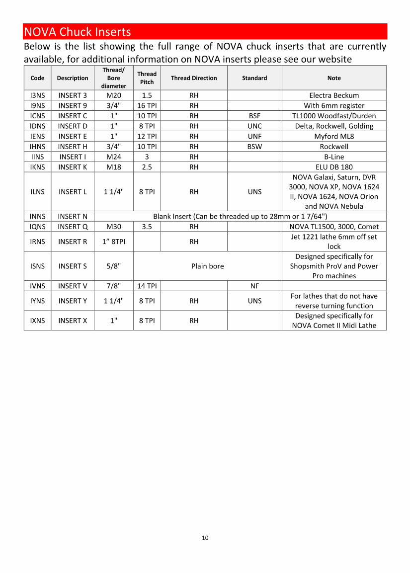
NOVA Chuck Inserts Below is the list showing the full range of NOVA chuck inserts that are currently available, for additional information on NOVA inserts please see our website
Code Description Thread/
Bore diameter
Thread Pitch Thread Direction Standard Note
I3NS INSERT 3 M20 1.5 RH Electra Beckum I9NS INSERT 9 3/4" 16 TPI RH With 6mm register ICNS INSERT C 1" 10 TPI RH BSF TL1000 Woodfast/Durden IDNS INSERT D 1" 8 TPI RH UNC Delta, Rockwell, Golding IENS INSERT E 1" 12 TPI RH UNF Myford ML8 IHNS INSERT H 3/4" 10 TPI RH BSW Rockwell IINS INSERT I M24 3 RH B-Line IKNS INSERT K M18 2.5 RH ELU DB 180
ILNS INSERT L 1 1/4" 8 TPI RH UNS
NOVA Galaxi, Saturn, DVR 3000, NOVA XP, NOVA 1624 II, NOVA 1624, NOVA Orion
and NOVA Nebula INNS INSERT N Blank Insert (Can be threaded up to 28mm or 1 7/64") IQNS INSERT Q M30 3.5 RH NOVA TL1500, 3000, Comet
IRNS INSERT R 1” 8TPI RH Jet 1221 lathe 6mm off set lock
ISNS INSERT S 5/8" Plain bore Designed specifically for
Shopsmith ProV and Power Pro machines
IVNS INSERT V 7/8" 14 TPI NF
IYNS INSERT Y 1 1/4" 8 TPI RH UNS For lathes that do not have reverse turning function
IXNS INSERT X 1" 8 TPI RH Designed specifically for NOVA Comet II Midi Lathe

11
PRO-TEK SUPERNOVA2 Chuck Parts View
12
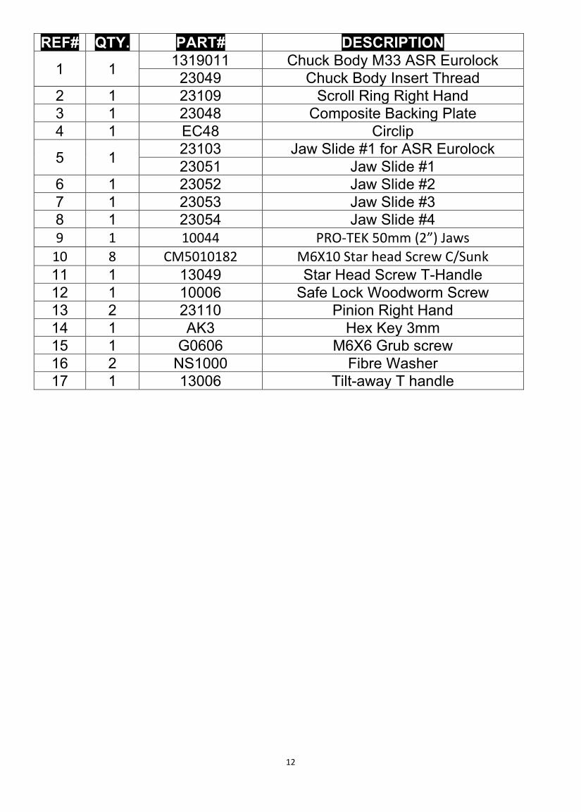
REF# QTY. PART# DESCRIPTION
1 1 1319011 Chuck Body M33 ASR Eurolock 23049 Chuck Body Insert Thread
2 1 23109 Scroll Ring Right Hand 3 1 23048 Composite Backing Plate 4 1 EC48 Circlip
5 1 23103 Jaw Slide #1 for ASR Eurolock 23051 Jaw Slide #1
6 1 23052 Jaw Slide #2 7 1 23053 Jaw Slide #3 8 1 23054 Jaw Slide #4 9 1 10044 PRO-TEK 50mm (2”) Jaws
10 8 CM5010182 M6X10 Star head Screw C/Sunk 11 1 13049 Star Head Screw T-Handle 12 1 10006 Safe Lock Woodworm Screw 13 2 23110 Pinion Right Hand 14 1 AK3 Hex Key 3mm 15 1 G0606 M6X6 Grub screw 16 2 NS1000 Fibre Washer 17 1 13006 Tilt-away T handle

13
Operation of the chuck Main functionality of the chuck is to grab and secure the workpiece by expanding or contracting its jaw slides. The jaw slides of the chuck can be operated by using the provided t-handle.
The image below illustrates how the chuck can be operated:
Mounting the jaws onto the chuck The PRO-TEK SUPERNOVA2 chuck is supplied with a set of Pro-Tek 50mm jaws (#6075). The jaws must be securely fastened for the chuck to serve its function correctly. Mounting procedure of the jaw applies to all NOVA accessory jaws. Please follow the steps below when mounting the jaws onto the chuck: 1. Ensure there are no dusts or debris
on the bottom surface of the jaw and top surface of the jaw slides.
2. Each jaw segment has a number
indented on the jaw edge to indicate its correct mounting position for minimal runout. Loosely screw the jaw segment onto the jaw slide with the number matching the jaw slide. The
Open
Close
14
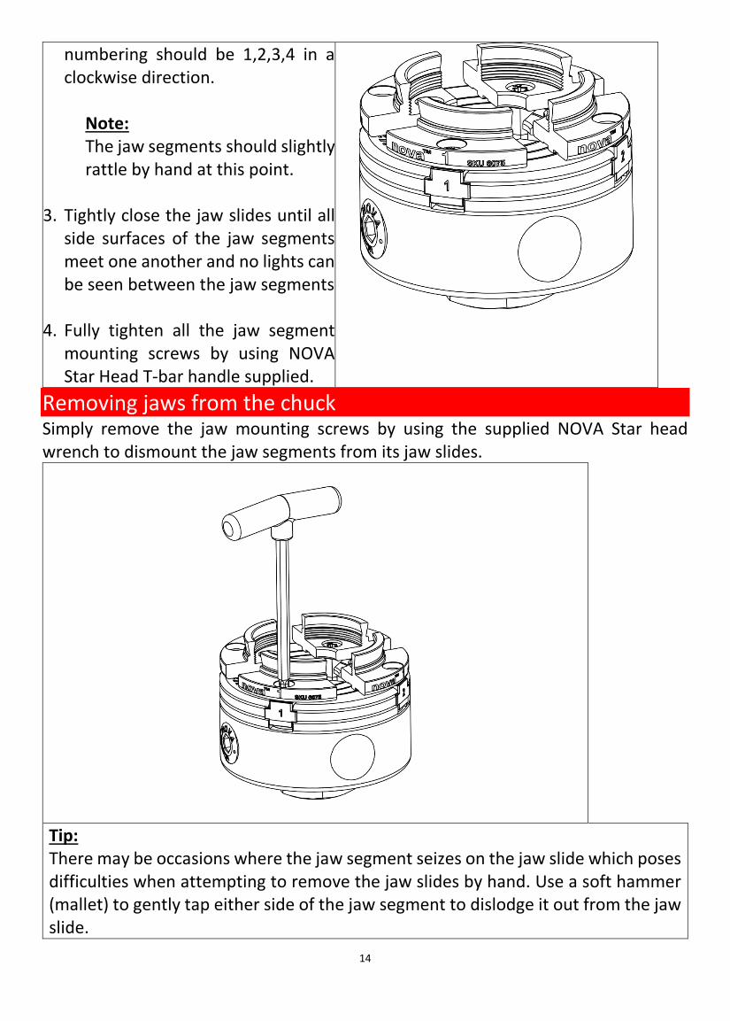
numbering should be 1,2,3,4 in a clockwise direction.
Note: The jaw segments should slightly rattle by hand at this point.
3. Tightly close the jaw slides until all side surfaces of the jaw segments meet one another and no lights can be seen between the jaw segments
4. Fully tighten all the jaw segment
mounting screws by using NOVA Star Head T-bar handle supplied.
Removing jaws from the chuck Simply remove the jaw mounting screws by using the supplied NOVA Star head wrench to dismount the jaw segments from its jaw slides.
Tip: There may be occasions where the jaw segment seizes on the jaw slide which poses difficulties when attempting to remove the jaw slides by hand. Use a soft hammer (mallet) to gently tap either side of the jaw segment to dislodge it out from the jaw slide.
15
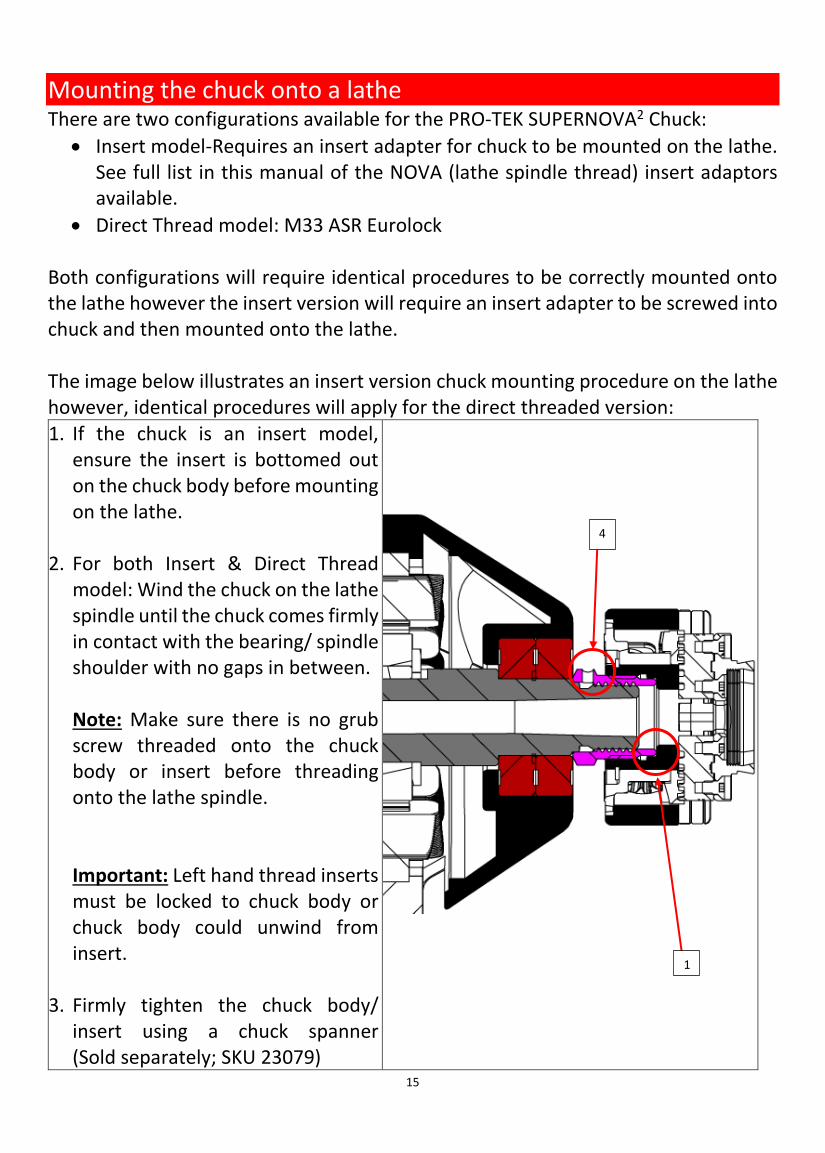
Mounting the chuck onto a lathe There are two configurations available for the PRO-TEK SUPERNOVA2 Chuck:
• Insert model-Requires an insert adapter for chuck to be mounted on the lathe. See full list in this manual of the NOVA (lathe spindle thread) insert adaptors available.
• Direct Thread model: M33 ASR Eurolock Both configurations will require identical procedures to be correctly mounted onto the lathe however the insert version will require an insert adapter to be screwed into chuck and then mounted onto the lathe. The image below illustrates an insert version chuck mounting procedure on the lathe however, identical procedures will apply for the direct threaded version: 1. If the chuck is an insert model,
ensure the insert is bottomed out on the chuck body before mounting on the lathe.
2. For both Insert & Direct Thread
model: Wind the chuck on the lathe spindle until the chuck comes firmly in contact with the bearing/ spindle shoulder with no gaps in between.
Note: Make sure there is no grub screw threaded onto the chuck body or insert before threading onto the lathe spindle. Important: Left hand thread inserts must be locked to chuck body or chuck body could unwind from insert.
3. Firmly tighten the chuck body/ insert using a chuck spanner (Sold separately; SKU 23079)
4
1

16
NOVA Chuck Spanner
4. Place the red thread protector
washer into the M6 threaded hole indicated in the image. Then wind the M6 grub screw in position and tighten with 3mm Hex head wrench (provided) which prevents the chuck from loosening from the lathe spindle.
17
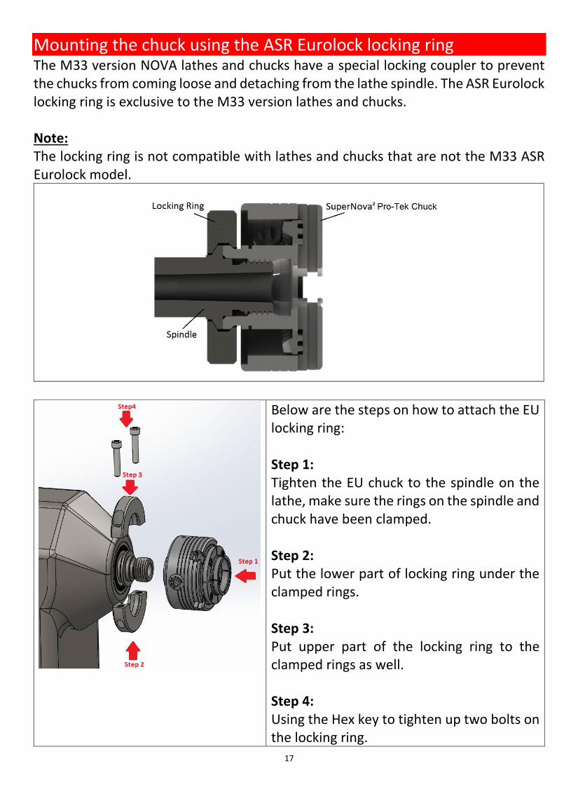
Mounting the chuck using the ASR Eurolock locking ring The M33 version NOVA lathes and chucks have a special locking coupler to prevent the chucks from coming loose and detaching from the lathe spindle. The ASR Eurolock locking ring is exclusive to the M33 version lathes and chucks. Note: The locking ring is not compatible with lathes and chucks that are not the M33 ASR Eurolock model.
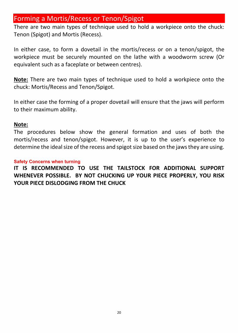
Below are the steps on how to attach the EU locking ring: Step 1: Tighten the EU chuck to the spindle on the lathe, make sure the rings on the spindle and chuck have been clamped. Step 2: Put the lower part of locking ring under the clamped rings. Step 3: Put upper part of the locking ring to the clamped rings as well. Step 4: Using the Hex key to tighten up two bolts on the locking ring.

18
Screw chuck – Safe Lock Woodworm Screw The Safe Lock woodworm screw (screw chuck) provides a convenient method for holding a bowl blank to cut a recess or spigot to mount on an accessory jaw. The accessory jaw segments must be properly mounted beforehand to use the woodworm screw. The woodworm screw is to be mounted inside the centre hole of the chuck as shown below: Open the jaw slides and insert the Safe Lock Woodworm screw in the center hole of the chuck. Position the Safe Lock Woodworm screw as shown as the image. Note: All 4 flat sides of the Safe Lock Woodworm screw should be in contact with the flat end of the jaw slides.
Make sure this flat face of the Safe Lock Woodworm screw comes in contact with the flat surface of the jaw slide

19
To use the Safe Lock Woodworm screw on a workpiece 1. Ensure the workpiece surface facing
the jaw segments that is flat as possible.
2. Drill an 8mm(.31”) diameter hole at approximately 19mm(0.74”) deep into the work piece
3. Firmly press the Safe Lock Woodworm screw into the pre-drilled hole on the workpiece and thread the workpiece onto the wood worm screw until the workpiece makes good contact with the mounted jaws on the chucks.
Caution – Maximum capacity and speed of Safe Lock Woodworm screw: DO NOT USE THE SCREW FOR VERY LARGE WOOD BLANKS. The Safe Lock Woodworm screw is intended for small bowl and screw chucking work. The maximum capacity which should be mounted on the screw - 250mm (10 inches) diameter x 100mm (4 inches). DO NOT EXCEED 600 RPM FOR THIS OPERATION. Use tailstock support whenever possible.
8mm diameter Hole. 19mm deep
20
Forming a Mortis/Recess or Tenon/Spigot There are two main types of technique used to hold a workpiece onto the chuck: Tenon (Spigot) and Mortis (Recess). In either case, to form a dovetail in the mortis/recess or on a tenon/spigot, the workpiece must be securely mounted on the lathe with a woodworm screw (Or equivalent such as a faceplate or between centres). Note: There are two main types of technique used to hold a workpiece onto the chuck: Mortis/Recess and Tenon/Spigot. In either case the forming of a proper dovetail will ensure that the jaws will perform to their maximum ability. Note: The procedures below show the general formation and uses of both the mortis/recess and tenon/spigot. However, it is up to the user’s experience to determine the ideal size of the recess and spigot size based on the jaws they are using. Safety Concerns when turning IT IS RECOMMENDED TO USE THE TAILSTOCK FOR ADDITIONAL SUPPORT WHENEVER POSSIBLE. BY NOT CHUCKING UP YOUR PIECE PROPERLY, YOU RISK YOUR PIECE DISLODGING FROM THE CHUCK
21
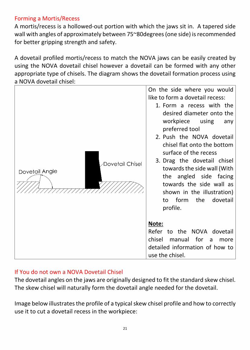
Forming a Mortis/Recess A mortis/recess is a hollowed-out portion with which the jaws sit in. A tapered side wall with angles of approximately between 75~80degrees (one side) is recommended for better gripping strength and safety. A dovetail profiled mortis/recess to match the NOVA jaws can be easily created by using the NOVA dovetail chisel however a dovetail can be formed with any other appropriate type of chisels. The diagram shows the dovetail formation process using a NOVA dovetail chisel:
On the side where you would like to form a dovetail recess:
1. Form a recess with the desired diameter onto the workpiece using any preferred tool
2. Push the NOVA dovetail chisel flat onto the bottom surface of the recess
3. Drag the dovetail chisel towards the side wall (With the angled side facing towards the side wall as shown in the illustration) to form the dovetail profile.
Note: Refer to the NOVA dovetail chisel manual for a more detailed information of how to use the chisel.
If You do not own a NOVA Dovetail Chisel The dovetail angles on the jaws are originally designed to fit the standard skew chisel. The skew chisel will naturally form the dovetail angle needed for the dovetail. Image below illustrates the profile of a typical skew chisel profile and how to correctly use it to cut a dovetail recess in the workpiece:

22
Keep the leading edge of the chisel flat onto the workpiece (i.e. Bottom surface of the mortis/recess). Move the chisel forward and out to form the recess to the required diameter and depth. Note: FOR SAFETY REASONS NOVA STRONGLY ADVISE AGAIST USING ANY OTHER TOOL APART FROM THE NOVA DOVETAIL CHISEL AND SKEW SCRAPER CHISEL. Recommended Diameter of the recess The suitable mortise/recess diameter is dependent on the accessory jaw that is mounted on the chuck. For the standard PRO-TEK 50mm jaws that is included in the package: The mortis/recess diameter should be ranging anywhere in between 55mm ~ 65mm (2.16” – 2.55”) General rule to determine the suitable diameter and depth of the recess:
1. Recess diameter should at least be 5mm 3/16” bigger than the outer diameter of the jaws when completely contracted on the chuck.
2. Recess diameter should at least be 5mm or 3/16” smaller than the outer diameter of the jaws when completely expanded on the chuck.

23
The mortis/recess depth should always be slightly shorter than the height of the mounted jaws.
The dovetail profile on a recess is used to lock the workpiece on the chuck when the jaws are expanded to hold the workpiece. This natural locking action provides significant level of gripping force.
The workpiece should never touch these parts of the jaws
The workpiece should only touch these two surfaces

24
The maximum speed allowed for a mortis/recess varies with the type of intended operation. This would mostly be based upon the user experience of the user, size of material being turned, quality of the material being turned and how balanced the piece is. Therefore, consult with a skilled professional for the maximum speed limits for your workpiece if you are not confident with your chucking technique. Forming a Tenon/Spigot A tenon/spigot is a protruding cylinder formed for the accessory jaw segments to securely grip the workpiece. The length of the spigot should be slightly shorter than the internal height of the jaws you are using.
It is recommended turn between centres for all pieces whenever possible Ensure the side surface of the tenon/spigot has the proper dovetail profile. If the spigot (tenon) is straight, the piece may not be secured properly and dislodge from the chuck.
The workpiece should never touch these parts of the jaws
The workpiece should only touch these two surfaces
25
Safety Warning: Thoroughly inspect the wood for splits or weaknesses, especially around the tenon/spigot area, before mounting the workpiece onto the chuck. The spigot will be the only area of contact when doing free end turning. Never proceed on turning the wood if any weaknesses are found on the wood. Recommended diameter for the tenon/spigot The suitable tenon/spigot diameter is dependent on the jaws that are mounted on the chuck. General rule to determine the suitable diameter and length of the tenon/spigot:
1. Tenon/spigot diameter should be 6mm larger than the internal diameter of the jaws when completely contracted on the chuck.
2. Tenon/spigot diameter should be 6mm smaller than the internal diameter of the jaws when completely expanded on the chuck.
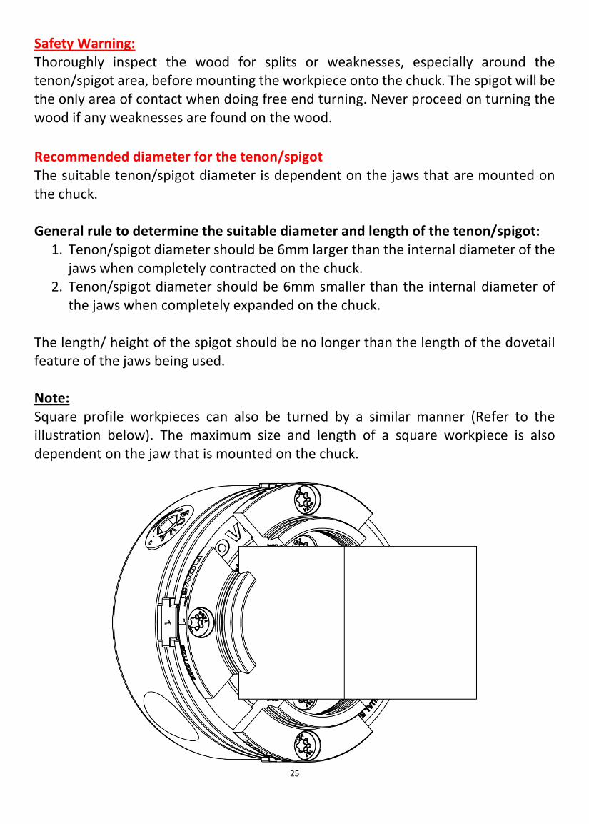
The length/ height of the spigot should be no longer than the length of the dovetail feature of the jaws being used. Note: Square profile workpieces can also be turned by a similar manner (Refer to the illustration below). The maximum size and length of a square workpiece is also dependent on the jaw that is mounted on the chuck.
26
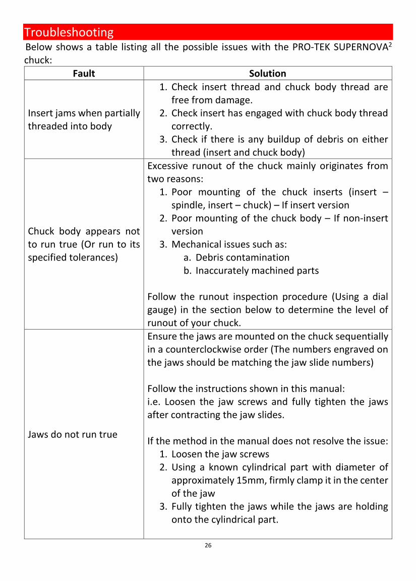
Troubleshooting Below shows a table listing all the possible issues with the PRO-TEK SUPERNOVA2 chuck:
Fault Solution
Insert jams when partially threaded into body
1. Check insert thread and chuck body thread are free from damage.
2. Check insert has engaged with chuck body thread correctly.
3. Check if there is any buildup of debris on either thread (insert and chuck body)
Chuck body appears not to run true (Or run to its specified tolerances)
Excessive runout of the chuck mainly originates from two reasons:
1. Poor mounting of the chuck inserts (insert – spindle, insert – chuck) – If insert version
2. Poor mounting of the chuck body – If non-insert version
3. Mechanical issues such as: a. Debris contamination b. Inaccurately machined parts
Follow the runout inspection procedure (Using a dial gauge) in the section below to determine the level of runout of your chuck.
Jaws do not run true
Ensure the jaws are mounted on the chuck sequentially in a counterclockwise order (The numbers engraved on the jaws should be matching the jaw slide numbers) Follow the instructions shown in this manual: i.e. Loosen the jaw screws and fully tighten the jaws after contracting the jaw slides. If the method in the manual does not resolve the issue:
1. Loosen the jaw screws 2. Using a known cylindrical part with diameter of
approximately 15mm, firmly clamp it in the center of the jaw
3. Fully tighten the jaws while the jaws are holding onto the cylindrical part.

27
If the jaws are still running out of true, use a dial gauge to measure the radial and axial runout of the jaws when it is mounted on the chuck properly. The runout should be measured between the ranges of the following:
1. Radial runout 2. Axial runout
Contact our customer services if the jaws are running out of the maximum runout range above when they are correctly mounted on the chucks.
Jaw Slides closed to center and No. 1 Slide stays in center when jaws are expanded again
The jaw slides may have over travelled and got dislocated from the scroll ring. Ideally a complete disassemble and assembly is required to correctly place the jaw slides in place. By reassembling the chuck, it allows for an opportunity to inspect all the chuck parts for any defects (Especially around the scroll ring area).
Chuck very stiff to operate or jammed
Wood dusts will accumulate between parts over a period of use. The wood dusts contaminate and degrade the performance of the internal grease/ lubricants causing them to become very stiff. When the grease/ lubricant becomes degraded, it must be replaced with new lubricants to restore its performance. Disassemble, clean all parts, apply new grease/ lubricants on all necessary parts and reassemble the chuck.
Jaw Slides when wound to center do not meet
The jaw slides may have not engaged in the correct sequence or it may not be engaged with the correct teeth of the scroll ring. First, ensure the jaw slides are inserted in a sequential order in the counterclockwise direction. Secondly, disassemble the chuck and physically place the jaw slides in the center and engage the scroll ring.
When chuck is being removed from spindle the body unwinds from insert
Either lock insert in body using grub screw and fiber washer provided or use insert spanner on the insert to wind chuck off lathe.

28
Chuck jams on lathe spindle
This is a common problem with fixtures on a lathe. To help prevent it try a plastic or fiber washer between insert/chuck and spigot shoulder of spindle. Greasing of insert face and spindle can also help. Note Use of plastic spindle washers could affect accuracy.
Safe Lock Woodworm screw creeps forward or is not seated properly in chuck
Ensure the Safe Lock Woodworm screw is placed correctly between jaw slides and behind the jaws
Wooden tenon shifts during turning
Check that the tenon area is made correctly for jaws to grip. Check that the tenon is not oversized or undersized. See tenon operation instructions. Use careful chisel techniques that do not exert excessive pressure. Irregular rough wood blanks need to be checked to see if there is enough jaw surface contact.
Wood blank does not seat properly in internal mortise mounting
Check the angle of the dovetail made in the mortise is the same angle as the jaws. Make sure the bottom of the recess is flat and square to face. Check that the bowl is not incorrectly riding on the flat shoulder of at the base of the jaws.
Chuck runout inspection procedure The runout tolerance is specified at the chuck body and not on the workpiece. Generally, wood is a flexible material which makes it an insufficient medium to measure accuracy. Radial runout values on a workpiece is amplified as the length of the workpiece increases therefore the measurements must be taken at the chuck body to standardize the procedure. Equipment Required A Dial Test Indicator (DTI) is required to inspect and quantify the level runout on the chuck.
29
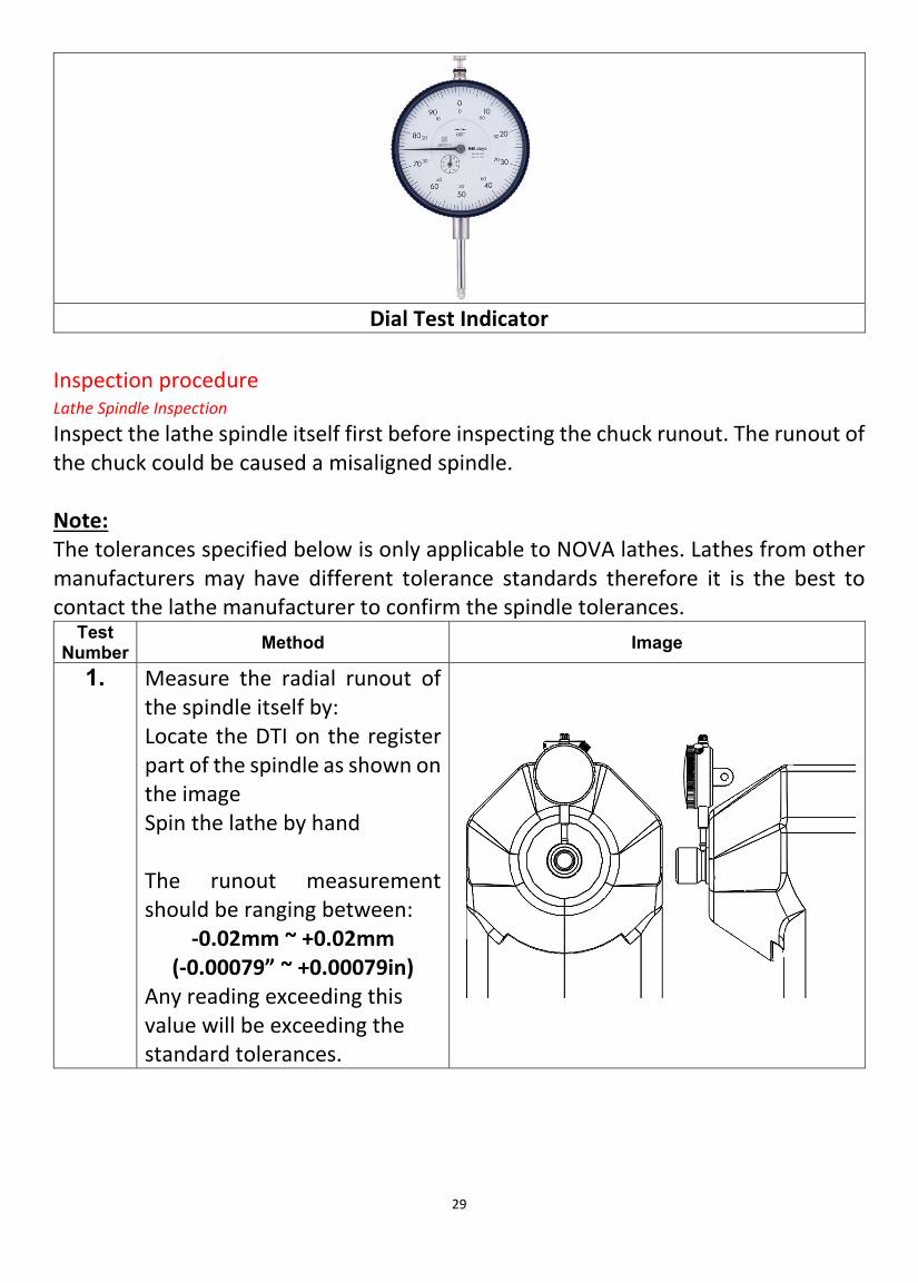
Dial Test Indicator
Inspection procedure Lathe Spindle Inspection Inspect the lathe spindle itself first before inspecting the chuck runout. The runout of the chuck could be caused a misaligned spindle. Note: The tolerances specified below is only applicable to NOVA lathes. Lathes from other manufacturers may have different tolerance standards therefore it is the best to contact the lathe manufacturer to confirm the spindle tolerances.
Test Number Method Image
1. Measure the radial runout of the spindle itself by: Locate the DTI on the register part of the spindle as shown on the image Spin the lathe by hand The runout measurement should be ranging between:
-0.02mm ~ +0.02mm (-0.00079” ~ +0.00079in)
Any reading exceeding this value will be exceeding the standard tolerances.
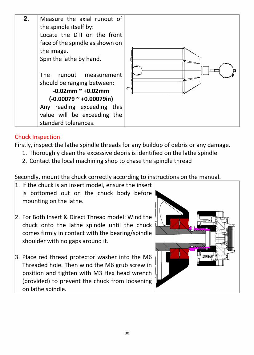
30
2. Measure the axial runout of the spindle itself by: Locate the DTI on the front face of the spindle as shown on the image. Spin the lathe by hand. The runout measurement should be ranging between:
-0.02mm ~ +0.02mm (-0.00079 ~ +0.00079in)
Any reading exceeding this value will be exceeding the standard tolerances.
Chuck Inspection Firstly, inspect the lathe spindle threads for any buildup of debris or any damage.
1. Thoroughly clean the excessive debris is identified on the lathe spindle 2. Contact the local machining shop to chase the spindle thread
Secondly, mount the chuck correctly according to instructions on the manual. 1. If the chuck is an insert model, ensure the insert
is bottomed out on the chuck body before mounting on the lathe.
2. For Both Insert & Direct Thread model: Wind the
chuck onto the lathe spindle until the chuck comes firmly in contact with the bearing/spindle shoulder with no gaps around it.
3. Place red thread protector washer into the M6
Threaded hole. Then wind the M6 grub screw in position and tighten with M3 Hex head wrench (provided) to prevent the chuck from loosening on lathe spindle.

31
Test Number Method Image
1. Measure the radial runout of the attached faceplate by: Locate the DTI perpendicular to the spindle rotation axis as shown in the image. Spin lathe by hand. The runout measurement should be ranging between: -0.15mm ~ +0.15mm (±0.006in)
Any reading exceeding this value will be exceeding the standard tolerances.
2. Measure the axial runout of the attached tool by: Locate the DTI in the position shown in the image. Spin lathe by hand. The runout measurement should be ranging between: -0.08mm ~ +0.08mm (±0.0031in) Any reading exceeding this value will be exceeding the standard tolerances. Another view of dial indicator location on face of chuck.
32
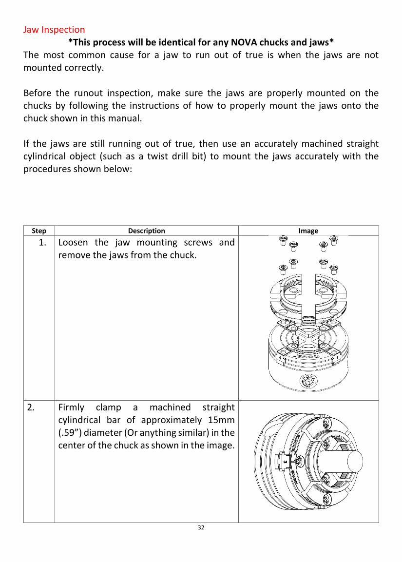
Jaw Inspection *This process will be identical for any NOVA chucks and jaws*
The most common cause for a jaw to run out of true is when the jaws are not mounted correctly. Before the runout inspection, make sure the jaws are properly mounted on the chucks by following the instructions of how to properly mount the jaws onto the chuck shown in this manual. If the jaws are still running out of true, then use an accurately machined straight cylindrical object (such as a twist drill bit) to mount the jaws accurately with the procedures shown below:
Step Description Image 1. Loosen the jaw mounting screws and
remove the jaws from the chuck.
2. Firmly clamp a machined straight cylindrical bar of approximately 15mm (.59”) diameter (Or anything similar) in the center of the chuck as shown in the image.

33
3. Tighten the jaw segments while clamping on the cylindrical bar.
PRO TEK SUPERNOVA2 Chuck Maintenance This section introduces the procedures on how to assemble and disassemble the PRO-TEK SUPERNOVA2 chuck for maintenance. Regular maintenance is essential to ensure maximum performance for any mechanical devices including the PRO-TEK SUPERNOVA2 chuck. Attempt to clean and lubricate the chuck components as the first step if the chuck feels / has become stiff to operate. Required tools
1. 1 ½” Spanner 2. Circlip pliers (External) 3. 3mm Hex key 4. Flat head screw drivers (x2) 5. Plastic hammer (or block of wood) 6. Multi-purpose grease (Ideally a heavily viscous type) 7. Long piece of timber which can be fitted between the jaws when opened

34
Removing the chuck from the lathe Note for insert type chucks: After a long time, the chuck inserts tend to become stuck/ seized onto the chuck body. It is recommended to remove the chuck body from the insert while the chuck is mounted onto the lathe spindle. Step No. Image Description
1.
Using the 3mm Hex key, Remove the M6 grub screw which prevents the insert from unscrewing during operation. Note: For the insert version chuck, there may be 2 (One for the insert and lathe, another for the insert and chuck body)
2.
Lock the lathe spindle from turning by engaging the index locking feature.
3.
*For insert chucks* Open the jaws and fit the long piece of timber between the jaws as shown in the image. Securely hold the insert portion of the chuck with the 1 ½” spanner and turn the timber Counter-clockwise direction to screw off the chuck body from the insert.
35
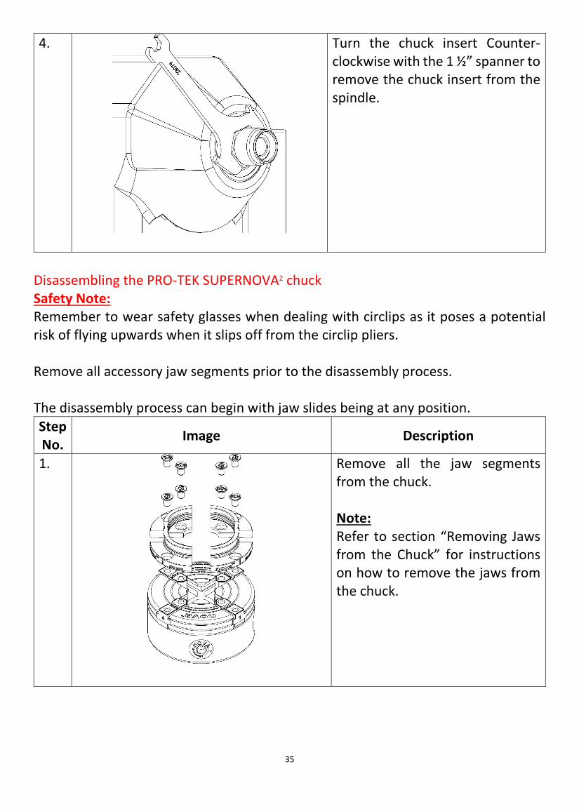
4.
Turn the chuck insert Counter-clockwise with the 1 ½” spanner to remove the chuck insert from the spindle.
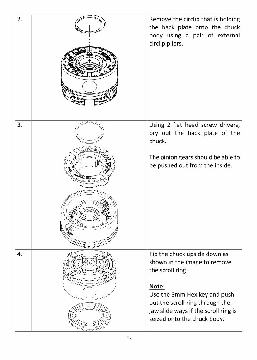
Disassembling the PRO-TEK SUPERNOVA2 chuck Safety Note: Remember to wear safety glasses when dealing with circlips as it poses a potential risk of flying upwards when it slips off from the circlip pliers. Remove all accessory jaw segments prior to the disassembly process. The disassembly process can begin with jaw slides being at any position. Step No. Image Description
1.
Remove all the jaw segments from the chuck. Note: Refer to section “Removing Jaws from the Chuck” for instructions on how to remove the jaws from the chuck.
36
2.
Remove the circlip that is holding the back plate onto the chuck body using a pair of external circlip pliers.
3.
Using 2 flat head screw drivers, pry out the back plate of the chuck. The pinion gears should be able to be pushed out from the inside.
4.
Tip the chuck upside down as shown in the image to remove the scroll ring. Note: Use the 3mm Hex key and push out the scroll ring through the jaw slide ways if the scroll ring is seized onto the chuck body.

37
5.
Slide out all of the jaw slides by hand to complete the disassembly process.
Parts to clean and inspect on the disassembled chuck Following list indicates the area of parts where cleaning and inspection is required when the chuck operation becomes difficult:
• Jaw slideways (Chuck body) • Jaw slides
• Scroll ring spiral teeth • Gear teeth (Scroll ring, hex pinion)
Reassembly of the SUPERNOVA2 Pro-Tek chuck Safety Note: Remember to wear safety glasses when dealing with circlips as it poses a potential risk of flying upwards when it slips off from the circlip pliers. Step No. Image Description
1.
Apply grease onto surfaces that contacts
each other which is
indicated in the image.
Note:
Carry out the assembly

38
process on a relatively clean environment to
prevent contamination of the grease
which shortens the grease life.
2.
Insert the jaw slides back into the jaw slideways of the chuck body. Ensure the jaw slides are inserted in a Counter-Clockwise order. Note: There is no dedicated slot assigned to each of the jaw slides
3.
Position the jaw slides in the middle to form a small square at the centre of the chuck.
39
4.
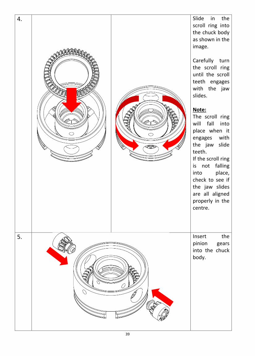
Slide in the scroll ring into the chuck body as shown in the image. Carefully turn the scroll ring until the scroll teeth engages with the jaw slides. Note: The scroll ring will fall into place when it engages with the jaw slide teeth. If the scroll ring is not falling into place, check to see if the jaw slides are all aligned properly in the centre.
5.
Insert the pinion gears into the chuck body.
40
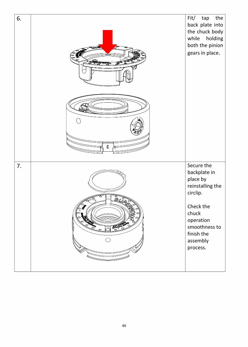
6.
Fit/ tap the back plate into the chuck body while holding both the pinion gears in place.
7.
Secure the backplate in place by reinstalling the circlip. Check the chuck operation smoothness to finish the assembly process.

41
Go to Teknatool.com to learn more about our full assortment of accessories
727-954-3433 [email protected] Teknatool International
4499 126th Ave. N, Clearwater, Florida 33762 © Teknatool® International 2020
All rights reserved. Teknatool® USA Inc.
WARRANTY: This Teknatool product is backed by a warranty period of 6 years from the date of purchase. Teknatool International hereby agrees to make repairs or replace components without charge for any defects due to faulty material or workmanship, provided that;
1. The warranty period has not elapsed. Proof of purchase date (sales slip etc) would need to be forwarded to Teknatool International Ltd.
2. If in our opinion upon examination, the product has been altered, repair, or modified in any wat that would affect its operation; has not been subjected to misuse, negligence, accident or not used strictly in accordance with instructions provided
3. Where necessary transportation is prepaid by customer to Factory Service Center, or authorized Teknatool Service Center.
Warranty does not cover any cost or damaged arising directly or inadvertently from the operation if this Teknatool product. No other guarantee, written or verbal is authorized by Teknatool International Ltd. INTERNATIONAL CUSTOMERS: Our Teknatool agents may issue their own Warranty in addition to our warranty policy to cover this product. Their legal terms may vary from those stated above, please check with your dealer. Our policy is one of continuous improvement. We therefore reserve the right to change specification/design without notice. REGISTER YOUR WARRANTY WITH TEKNATOOL INTERNATIONAL ONLINE! www.teknatool.com