Pro-C Controller - SPRINKLER TALK · Pro-C Controller A Complete Family of Full-featured Indoor and...
36
® PRODUCT INFORMATION Pro-C Controller A Complete Family of Full-Featured Residential and Light Commercial Controllers P R O - C C O N T R O L L E R ®
Transcript of Pro-C Controller - SPRINKLER TALK · Pro-C Controller A Complete Family of Full-featured Indoor and...

®
P R O D U C T I N F O R M A T I O N
Pro-C ControllerA Complete Family of Full-Featured Residential
and Light Commercial Controllers
PR
O-
CC O N T R
OL
LE
R
®

®
ii
Pro-C ControllerProduct Overview .................................................................................1
Product Features and Benefits ..............................................................2
Product Comparisons ..........................................................................11
Technical Information .........................................................................12
Product Explanation ............................................................................12
Installation ..........................................................................................13
Programming ......................................................................................17
Troubleshooting Guide .......................................................................23
SRR Remote ControlProduct Overview ...............................................................................24
Product Features and Benefits ............................................................24
Installation and Programming .............................................................26
Technical Information .........................................................................30
TABLE OF CONTENTS

1
Pro-C Controller
A Complete Family of Full-featured Indoor and Outdoor Residential and Light Commercial ControllersFor the end user, for the contractor...there has never been a residential and light commercial controller so remarkably easy to handle as this. Presenting the new Hunter Pro-C Controller.
Borrowing the innovative concept of modular design from its big brother, the ICC, this latest addition to the Hunter product line-up is destined to become the leading controller in its market segment in the years to come. Starting with a base model of 3 stations, it is possible to expand the controller up to 15 stations simply by adding plug-in modules. So, thereʼs no need to bring along a variety of different-sized controllers to see which one is best for the job. With its ability to customize to the particular size you need, the Pro-C will always be the right choice. Being a modular system, the new Pro-C also makes inventory a breeze for contractors—there are only three different units to stock (indoor cabinets, outdoor cabinets and station modules).
But, modularity isnʼt all this controller has to offer, with great features such as three programs with multiple start times, independent day scheduling options, “one touch” manual start and rapid advance, a programmable event day off, robust heavy-duty locking plastic cabinet, and superior surge protection.
The Pro-C controller: delivering maximum flexibility for landscapes that require a minimal number of stations.
PRODUCT OVERVIEW
PR
O-
CC O N T R
OL
LE
R
®

2
FEATURES AND BENEFITS
Outdoor or Indoor Models Available A versatile controller, covering the needs of any installationThe Pro-C controller is offered as an outdoor model when the need for weather resistance is required and as an indoor model for installa-tions where protection from the elements is available. Both models are listed with UL and CE.
Modular Design One controller does it all; no need to stock or carry multiple units Hunter is a leader in fulfilling customer wishes and the Pro-C controller simply the latest in a long history of quality irrigation products. Here is an impressive controller, with its modular design for inventory management, three stations factory installed, and the ability to easily add more stations, this is one well-conceived controller that will satisfy both contractor and end user alike.
“Custom-tailored” to the Project. Start with the PC-300 outdoor or PC-300i indoor 3-station controller base model and then customize it to your project with the addition of the PCM-300 3-station plug-in modules. The PCM-900 9-station module can also be added to expand the Pro-C station capacity to 15 stations. One to three additional modules can be added covering the zone requirements of the majority of all residential and light
Outdoors
Indoors
commercial jobs. No longer does the installer have to spend extra money on a controller with extra zones that arenʼt necessary.
Easy Inventory Management. Now, only one controller need be stocked for all projects. With its modularity, the Pro-C can be called out as a 3-, 6-, 9-, 12- or 15-station controller on most irrigation designs, making it the only controller necessary to keep on hand. Simply stock the base unit for all jobs and keep a box of modules to easily add stations to the controller as required.
Modular Design Eliminates Service Hassles. When heavy electrical surges (lightning) hit a controller, the damage it inflicts can occur in the primary or secondary circuitry. The Pro-C is the easiest controller to service with its readily removable primary power and station modules. Because of the modular design, when clock repair is necessary, the simple repair process is to extract the damaged module from the unit and replace. The contractor will find that there is no requirement to remove the controller from the wall.
Future Expansion. Easy addition of stations is a component of the modular concept. When your customers add on to their landscapes in future projects, the Pro-C is up to the task. The PCM station modules can be added, to make future expansion a breeze.
Large LCD Display Easy to read for schedule review and entry The large LCD display simplifies programming, making it easy to read and verify. In low light conditions, a large display is a welcome sight to any user.
3
Pro-C Controller
Non-volatile Memory Holds programs indefinitely; excellent insurance against unreliable power The Pro-C has what every user of electronic controllers has wished for: the ability to keep all programs in memory without a backup battery. In the event of a power failure or if AC power is suspended from the controller by the user, the Pro-Cʼs non-volatile memory will maintain programs forever, without need for a battery. Normal watering will resume when AC power is restored.
No Battery Required Maintain time of day up to four weeks The circuitry of the Pro-C has such low power consumption that the controller will accurately track the time of day for up to four weeks after AC power has been removed from the controller by the user or in the event of a power outage. This timekeeping occurs
without need for a battery. When power is restored the controller will continue to water, right on schedule. The controller will also reset its
circuits to allow another 4 weeks of time keeping.
Self-Diagnostic Electronic Short Circuit Protection No fuses to worry about; only faulty stations stop watering The Pro-C automatically skips shorted stations allowing the rest of the system to operate as normal. The self-diagnostic electronic short circuit protection system is very beneficial to the user because of its ability to aid in identifying field wiring problems. It is almost as if the controller can trouble-shoot the system itself.
The self-diagnostic system detects a high current path—a “short”—through an operating station (the most common causes of shorts are faulty solenoids or when a bare valve common wire touches a bare station control wire). When a short circuit is detected on a station, instead of blowing a fuse which would shut down the entire irrigation system, the controller will skip over that station and continue to water the rest of the zones in the program. The controller will indicate what zone is shorting by showing the station number followed by ERR in the LCD display. The controller will continue to “jump over” that zone during every watering until the zone is repaired. To remove the ERR message from the display, just turn the dial or push any button.

4
Intuitive Dial Programming For easy program entry For contractors and homeowners alike, the Pro-C provides step by step programming. No complicated entry functions or repetitive keystrokes. Just turn the dial to the section of the program that needs to be changed and use the plus, minus and next buttons to make the adjustments. No other programming method is easier.
Removable Front Panel for Remote Programming Set the controller up without having to stand in front of it A removable hinge design allows easy removal of the front panel without disturbing field wiring. With the use of a 9-volt battery, you can set the program away from the cabinet location. This timesaving feature allows the contractor to program before going out to the job (also serves as a great sales demo when talking to a potential client). The contractor can also give the homeowner the front panel while the job is being installed to allow the homeowner to try the programming functions early on. When it comes time to actually set up the controller, the homeowner is completely clued in, making the whole programming process a very simple one.
FEATURES AND BENEFITS (continued)
3 Programs (A, B, C) with Multiple Start Times Different watering requirements are met with independent programming The Pro-C allows for many different irrigation applications using three completely independent programs. This is ideal for various types of plants that have separate watering day requirements. Each program has the ability to water up to four start times per day. The user has complete flexibility with watering schedules for new seed or sod lawns, multiple cycles for low infiltration-rate soils, slopes, morning or evening irrigation and other watering window restrictions.
Up to Six-hour Station Run Times Allows accurate watering for all types of plant material Each station will operate up to six hours of run time in any or all three programs. Run times from 0-120 minutes program in one-minute increments and then in ten-minute increments up to six hours. The factory default for all stations is set at 0 minutes to eliminate any unneeded stations before programming. Note: Using the water budget feature, station
run times may only be increased to a maximum of 6 hours.
Choice of Independent Day Scheduling Options Days of the week or 31-day interval for maximum flexibility The watering day schedules in programs A, B or C may be set up independently from each other. In each program, the choice of Custom (day of the week), Interval (up to 31-days), Odd or Even days may be selected. This allows the user to water on certain days of the week such as Monday, Wednesday and Friday or water on a repeating day cycle (Interval) such as every third day, or odd/even days in any or all three of the programs.

5
Pro-C Controller
365-day Calendar with Leap Year Intelligence True odd or even day programming In many areas of the United States, summer water rationing is a way of life. With its 365-day, leap year intelligent calendar the Pro-C makes programming true Odd/Even day watering possible, automatically correcting for 31-day months. Interval or Day of the Week scheduling is possible as well, to cover any watering day restrictions that may be enacted.
Superior Surge Protection All microcircuits are protected from electrical spikes/lightning The Pro-C is equipped with electronic components called MOVs (Metal-Oxide Varistor). These MOVs are designed to shunt electrical surges away from microcircuits through the controllerʼs grounding circuit. The Pro-C uses these MOVs to protect the controller from minor power surges coming in through the primary (110/230VAC) input side and also the secondary output side (24VAC).
MetalOxide
Varistors
Note: For proper results, the ground circuit must measure 10 ohms or less.
Global Water Budget/Seasonal Adjustment Changing run times could not be easier, from 10% to 150% The water budget/seasonal adjustment setting allows the user to make global changes to the run times of each zone from 10-150 percent of the original programmed run time in 10 percent increments. This feature is perfect for making small changes that are necessary as the weather changes, without reprogramming the entire controller. A unique bar graph (thermometer display) in the large LCD display lets the programmer know at a glance what percent from the original settings the controller is operating the station run times. The ability to immediately view the recalcu-lated run times for each of the zones is another unique feature built into the seasonal adjustment.Note: The controller should always be initially
programmed in the seasonal adjustment in the 100% position.

6
Weather Sensor Compatible Built-in bypass switch eliminates extra watering The Pro-C allows easy connection of any rain or weather sensor device including the Hunter Rain-Clik™, along with other Hunter sensors. With the sensor circuit on the controller, wiring is fast and easy. Thereʼs a built-in bypass switch to turn off the sensor for maintenance. Best of all, the controller will display Sen Off in the LCD display indicating when the sensor is interrupting irrigation. In all cases, use of the sensor does not alter any programmed watering schedule. The hookup is as simple as removing the jumper that is attached across the SEN terminals of the controller and connecting the sensor wires to the terminals.
Programmable Event Day(s) Off Maximum versatility when keeping the water off is important Need to make certain that the controller does not water on a specific day or days of the week? The Pro-C handles this task with ease. When Interval programming has been selected as the Day Schedule this event day off programming overrides the interval function to keep the controller always off on the day(s) selected. For example, an interval program is scheduled to water every third day but Saturdays have been designated as a “mow day,” so no watering can occur. Under the Event Day Off selection, Saturdays can be turned off. Sports fields, community centers, schools and parks will find this feature satisfies their requirements in this regard.
FEATURES AND BENEFITS (continued)
One Touch Manual Start and Rapid Advance Simple operation for a quick check of zones The One Touch Start and Rapid Manual Advance feature increases user-friendliness of the controller by using fewer steps to activate stations. This feature is great for a quick cycle when extra watering is needed or if you would like to scroll through the stations to inspect the system.
Remote Ready Provide your controller with simple and reliable operation away from its mounting location The Pro-C is remote ready! A SmartPort® harness is supplied with the Pro-C controller to permit the attachment of a Hunter SRR or ICR remote receiver. The SRR remote control is great for residential/light commercial sites, and offers features that other remotes canʼt at a price that canʼt be beat. The ICR remote control provides the installer maximum range capability (up to 2 miles) for large commercial sites. These easy to install remotes can save time and money by allowing remote valve operation away from the controller.
Rain-Clik™
7
Pro-C Controller
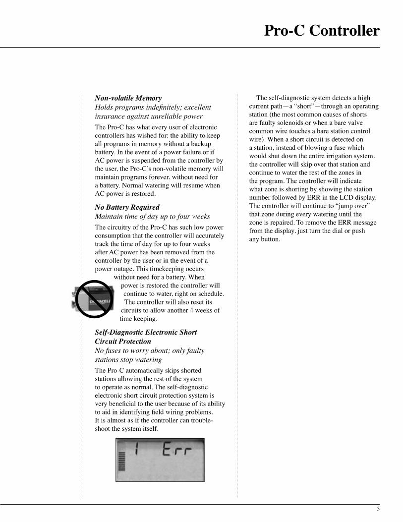
Heavy-Duty Cabinet Built to overcome the elements— for a long time The Pro-C is built using a robust heavy-duty plastic UL listed and NEMA 3R rated cabinet, which is not subject to UV degradation or color changes. For faster installation, the cabinet door hinge pin is removable when the door is unlocked and open. In addition, the cabinet uses the same professional key lock on the outdoor model as the Hunter ICC commercial controller. The Pro-C cabinet is also designed with a ¾"-1" knockout option on the back of the cabinet, and a 1" opening for low voltage and a ½" opening for high voltage in the bottom of the cabinet to accommodate the wiring needs of any job.
Programmable 0-7 Day Rain Delay No need to return to the controller to turn it back on The Pro-C allows you to turn off the controller for a predetermined period of time (1-7 days) during rainy weather. All programs are affected, as this delay is global. After the specified period has elapsed, the controller will return to automatic mode and water as scheduled. This delay feature is very convenient because when the controller is turned off for an event such as rain or a social activity, the operator will not have to make a trip to the site to reactivate the controller. In residential systems, when the operator uses the
watering delay feature thereʼs no need to worry about remembering that the controller has been turned off.
Programmable Delay Between Stations Slow closing valves and well recovery will never be an issue A programmable delay between stations solves the problem of slow closing valves because of a hydraulic overload condition. The delay also solves the problem of a system operating off of a slow filling well, allowing the well to recover between zones. The Pro-Cʼs programming will allow it to fit into any situation where a delay is necessary, as the delay is programmable up to four hours. Delays from 0 to 60 seconds are allocated in 5-second increments and then up to 4 hours in 1-minute increments. Note: If the MV circuit is programmed to operate on the zone, it will stay hot for the first minute of any programmed delay.

8
Pump Start/MV Circuit, Programmable By Station Activate a pump or master valve only when needed A programmable pump start circuit can activate a pump relay or master valve by individual zone. For systems that require only certain zones to receive a boost in pressure from a pump (such as rotor zones) this programmable MV circuit feature is the perfect solution, since it allows the pump to only operate when needed.
Internal Junction Box (on Outdoor Model Only) Primary power connection made inside the controller No extra trips to the distributor for a forgotten electrical box. The Pro-C comes with a primary power junction box built inside the cabinet. Installation time is reduced because a J-Box does not have to be fitted and screwed down tight. All that is required for proper installation is electrical conduit.
24VAC Valve Test Easy arrangement of zones during wire hookup When wiring up the controller so numbered irrigation zones will run in sequential order, installers find that an “always on” 24VAC valve test terminal post simplifies this process. Touching the valve wire to a hot 24 volt terminal to determine numbered zones without having to program a ʻmanual start ̓in the controller makes wire installation quick and efficient.
FEATURES AND BENEFITS (continued)
InternalJ-Box
Primary Voltage Source Choices Indoors or outdoors, operates off a variety of power sources Pro-C models can be supplied with a 115VAC/60 Hz transformer for domestic use or a 230VAC/50 Hz transformer for interna-tional use. This versatile transformer selection enables users to install the Pro-C anywhere in the world.
AM/PM or 24 Hour Clock Settings Choose your favorite method of timekeepingOperating the controller in either AM/PM mode or in 24-Hour mode is selectable by the user. The Pro-C allows the user to pick the time format that is most desirable. Wherever you are in the world, the Pro-C can operate under local time keeping preferences.
Single Station Manual Start If all that is needed is a little extra on a single zone! Many times throughout the year and for many reasons (e.g., watering fertilizer or pesticides into the soil, spot seeding), the user will want to add extra water to a particular zone. With single station manual start, the Pro-C is able to accomplish that task. Just turn the dial to Manual-One Station, use the arrow button to move to the desired station, then turn the dial to the Run position. The user may also increase or decrease the run time setting if preferred. After the zone is finished, the controller will return to automatic mode with its original schedule, even if modified for the manual operation.
9
Pro-C Controller
Start Time Stacking Prevent hydraulic overload Preventing hydraulic overload is very important when designing irrigation systems, especially residential ones. All electronic controllers such as the Pro-C allow the user to input start times into the programs that could cause the controller to overlap station run times. This occurs when the station run times add up to more minutes than the amount of time programmed between the start times. In the Pro-C, the start times will stack and not begin to actually water until the previous start time has completed its run through of all zones programmed. This great feature will eliminate the possibility of more than one zone operating at a time, causing the system to perform poorly when water pressure and flow are minimal.
Multi-language Capability User friendly in all parts of the world The Pro-C line is available as a multi-language controller family. Separate customization kits are available in Spanish (INT-451), French (INT-452), Italian (INT-453), and German (INT-454). These kits include an ownerʼs operation manual, door instruction card and a faceplate overlay that replaces the English version included with the controller.
Operate Three 7.2 VA Solenoids Simultaneously Able to accommodate larger water volume systems The Pro-C has the power capacity to operate up to three 7.2 VA solenoids simultaneously. There are times when the need to operate two valve solenoids off of one station terminal (and one solenoid on the pump start/MV terminal) is required. This type of operation may be the result of reduced watering windows, a retrofit with a city water system switching over to a water well system, or low volume (drip) zones added to regular zones. Whatever the reason may be, the Pro-C can handle it.
Assign Zones to Any or All Programs Complete versatility for any watering requirementAny station can be assigned to any or all programs in the Pro-C, making the Pro-C a truly versatile controller. This feature allows zones to have more than one watering schedule if required by the landscape.
Automated Chronological Ordering of Start Times No more “phantom” starts!When more than one start time is entered into a program, in any order of sequence, the Pro-C automatically shifts the start times in ascending order from the earliest start time to the latest start time. The Pro-C will also shift or “rubber band” the start times if times were inadvertently added after empty start time slots. The controller will fill the start #1 slot first, and then the #2 slot second, and so on making it easier for the user to check all times. No “phantom” starts will occur from an unknown start time buried deep in the program.
10
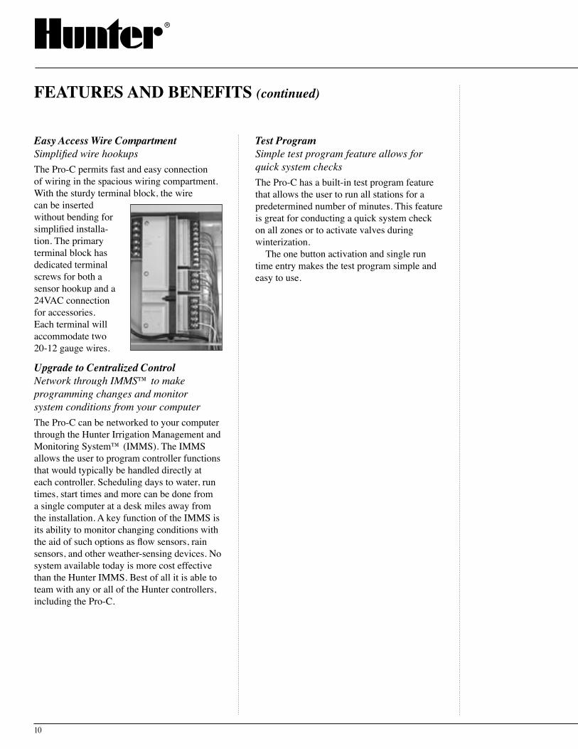
Easy Access Wire Compartment Simplified wire hookups The Pro-C permits fast and easy connection of wiring in the spacious wiring compartment. With the sturdy terminal block, the wire can be inserted without bending for simplified installa-tion. The primary terminal block has dedicated terminal screws for both a sensor hookup and a 24VAC connection for accessories. Each terminal will accommodate two 20-12 gauge wires.
Upgrade to Centralized Control Network through IMMS™ to make programming changes and monitor system conditions from your computerThe Pro-C can be networked to your computer through the Hunter Irrigation Management and Monitoring System™ (IMMS). The IMMS allows the user to program controller functions that would typically be handled directly at each controller. Scheduling days to water, run times, start times and more can be done from a single computer at a desk miles away from the installation. A key function of the IMMS is its ability to monitor changing conditions with the aid of such options as flow sensors, rain sensors, and other weather-sensing devices. No system available today is more cost effective than the Hunter IMMS. Best of all it is able to team with any or all of the Hunter controllers, including the Pro-C.
Test Program Simple test program feature allows for quick system checksThe Pro-C has a built-in test program feature that allows the user to run all stations for a predetermined number of minutes. This feature is great for conducting a quick system check on all zones or to activate valves during winterization.
The one button activation and single run time entry makes the test program simple and easy to use.
FEATURES AND BENEFITS (continued)
11
Pro-C Controller
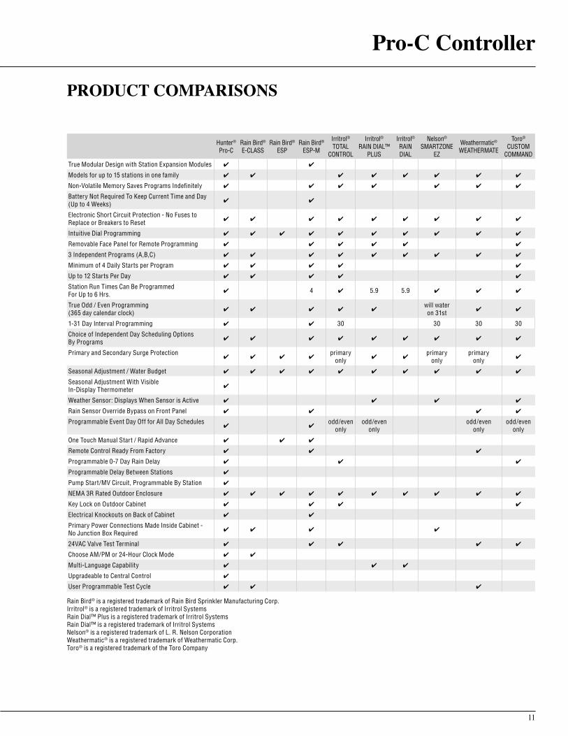
PRODUCT COMPARISONS
Hunter® Pro-C
Rain Bird® E-CLASS
Rain Bird® ESP
Rain Bird® ESP-M
Irritrol® TOTAL
CONTROL
Irritrol® RAIN DIAL™
PLUS
Irritrol® RAIN DIAL
Nelson® SMARTZONE
EZ
Weathermatic® WEATHERMATE
Toro® CUSTOM
COMMANDTrue Modular Design with Station Expansion Modules ✔ ✔
Models for up to 15 stations in one family ✔ ✔ ✔ ✔ ✔ ✔ ✔ ✔
Non-Volatile Memory Saves Programs Indefinitely ✔ ✔ ✔ ✔ ✔ ✔ ✔
Battery Not Required To Keep Current Time and Day (Up to 4 Weeks) ✔ ✔
Electronic Short Circuit Protection - No Fuses to Replace or Breakers to Reset ✔ ✔ ✔ ✔ ✔ ✔ ✔ ✔ ✔
Intuitive Dial Programming ✔ ✔ ✔ ✔ ✔ ✔ ✔ ✔ ✔ ✔
Removable Face Panel for Remote Programming ✔ ✔ ✔ ✔ ✔ ✔
3 Independent Programs (A,B,C) ✔ ✔ ✔ ✔ ✔ ✔ ✔ ✔ ✔
Minimum of 4 Daily Starts per Program ✔ ✔ ✔ ✔ ✔
Up to 12 Starts Per Day ✔ ✔ ✔ ✔ ✔
Station Run Times Can Be Programmed For Up to 6 Hrs. ✔ 4 ✔ 5.9 5.9 ✔ ✔ ✔
True Odd / Even Programming (365 day calendar clock) ✔ ✔ ✔ ✔ ✔
will water on 31st ✔ ✔
1-31 Day Interval Programming ✔ ✔ 30 30 30 30
Choice of Independent Day Scheduling Options By Programs ✔ ✔ ✔ ✔ ✔ ✔ ✔ ✔ ✔
Primary and Secondary Surge Protection✔ ✔ ✔ ✔
primary only ✔ ✔
primary only
primary only ✔
Seasonal Adjustment / Water Budget ✔ ✔ ✔ ✔ ✔ ✔ ✔ ✔ ✔ ✔
Seasonal Adjustment With Visible In-Display Thermometer ✔
Weather Sensor: Displays When Sensor is Active ✔ ✔ ✔ ✔
Rain Sensor Override Bypass on Front Panel ✔ ✔ ✔ ✔
Programmable Event Day Off for All Day Schedules✔ ✔
odd/even only
odd/even only
odd/even only
odd/even only
One Touch Manual Start / Rapid Advance ✔ ✔ ✔
Remote Control Ready From Factory ✔ ✔ ✔
Programmable 0-7 Day Rain Delay ✔ ✔ ✔
Programmable Delay Between Stations ✔
Pump Start/MV Circuit, Programmable By Station ✔
NEMA 3R Rated Outdoor Enclosure ✔ ✔ ✔ ✔ ✔ ✔ ✔ ✔ ✔ ✔
Key Lock on Outdoor Cabinet ✔ ✔ ✔ ✔
Electrical Knockouts on Back of Cabinet ✔ ✔
Primary Power Connections Made Inside Cabinet - No Junction Box Required ✔ ✔ ✔ ✔
24VAC Valve Test Terminal ✔ ✔ ✔ ✔ ✔
Choose AM/PM or 24-Hour Clock Mode ✔ ✔
Multi-Language Capability ✔ ✔ ✔
Upgradeable to Central Control ✔
User Programmable Test Cycle ✔ ✔ ✔
Rain Bird® is a registered trademark of Rain Bird Sprinkler Manufacturing Corp.Irritrol® is a registered trademark of Irritrol SystemsRain Dial™ Plus is a registered trademark of Irritrol SystemsRain Dial™ is a registered trademark of Irritrol SystemsNelson® is a registered trademark of L. R. Nelson CorporationWeathermatic® is a registered trademark of Weathermatic Corp.Toro® is a registered trademark of the Toro Company

12
Operating Specifications• Outdoor models, 115VAC transformer with
internal junction box• Indoor model, 115VAC two prong
plug-in transformer• Station output 24VAC .56 Amps• Transformer output 24VAC 1.0 Amps• Capable of operating equivalent of
3 solenoids simultaneously• Operating Temperature: 0 - 150 degrees F • NEMA rated outdoor cabinet• UL Listed
Dimensions• Indoor Model: 8.3" H x 9.6" W x 3.7" D• Outdoor Model: 8.9" H x 9.9" W x 4.3" D
ModelsPC-300i – base model indoor plastic cabinet
with plug-in 115VAC transformer, expands to 15 stations
PC-300 – base model outdoor locking plastic cabinet with 115VAC transformer, expands to 15 stations
PCM-300 – 3 station plug in module for use with any PC controller model
PCM-900 – 9 station plug in module for use with any PC controller model (expands Pro-C station capability to 15 stations with 1 PCM-300 installed)
TECHNICAL INFORMATION
Additional Features• 4 start times per program for repeat
watering needs• Removable front panel for field or
desktop programming; Panel interchange-able between indoor and outdoor units
• Up to six hours run time on all stations• Automated chronological ordering of start
times/start time stacking• 365-day calendar with leap year
intelligence• Programmable event day off allows specific
day(s) to be designated as always “off”• Rain Sensor bypass switch compatible
with micro-switch based sensors, displays when sensor is active
• Programmable delay between stations 0-4 hours for well recovery or slow-closing valves
• Programmable rain delay for 1-7 days• Compatible with Hunterʼs SRR and
ICR remote control systems• Upgradeable to central control with Hunter
IMMS™
S P E C I F I C A T I O N G U I D E
EXAMPLE: PC - 300i
MODELPC = Pro-C Controller
FEATURES300i = 3-Station Base Unit Controller, Indoor Model, Plug-in Transformer, Expands to 15 Stations300 = 3-Station Base Unit Controller, Outdoor Model, Internal Transformer, Expands to 15 Stations
PCM 300 = 3-Station Plug-in Module for use with any PC Controller Model900 = 9-Station Plug-in Module for use with any PC Controller Model
13
Pro-C Controller
INSTALLATION
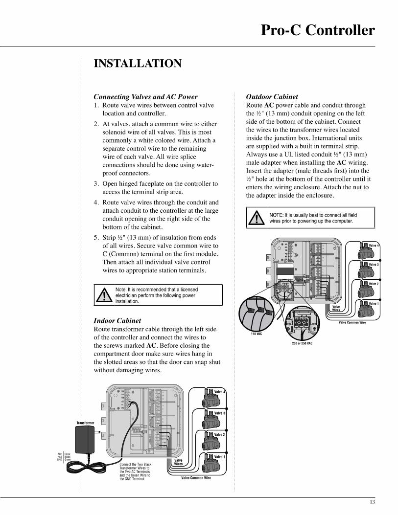
Connecting Valves and AC Power 1. Route valve wires between control valve
location and controller.2. At valves, attach a common wire to either
solenoid wire of all valves. This is most commonly a white colored wire. Attach a separate control wire to the remaining wire of each valve. All wire splice connections should be done using water-proof connectors.
3. Open hinged faceplate on the controller to access the terminal strip area.
4. Route valve wires through the conduit and attach conduit to the controller at the large conduit opening on the right side of the bottom of the cabinet.
5. Strip ½" (13 mm) of insulation from ends of all wires. Secure valve common wire to C (Common) terminal on the first module. Then attach all individual valve control wires to appropriate station terminals.
Note: It is recommended that a licensed electrician perform the following power installation.
Indoor Cabinet Route transformer cable through the left side of the controller and connect the wires to the screws marked AC. Before closing the compartment door make sure wires hang in the slotted areas so that the door can snap shut without damaging wires.
Transformer
Valve 1
Valve 2
Valve 3
Valve 4
3 Wires AC2 BlackAC1 BlackGND Green
Connect the Two BlackTransformer Wires tothe Two AC Terminalsand the Green Wire tothe GND Terminal alve Common Wire
alveWires
V
V
Outdoor Cabinet Route AC power cable and conduit through the ½" (13 mm) conduit opening on the left side of the bottom of the cabinet. Connect the wires to the transformer wires located inside the junction box. International units are supplied with a built in terminal strip. Always use a UL listed conduit ½" (13 mm) male adapter when installing the AC wiring. Insert the adapter (male threads first) into the ½" hole at the bottom of the controller until it enters the wiring enclosure. Attach the nut to the adapter inside the enclosure.
NOTE: It is usually best to connect all field wires prior to powering up the computer.
Valve Common Wire
Valve 1
Valve 2
Valve 3
Valve 4
ValveWires
230 or 250 VAC
110 VAC
14
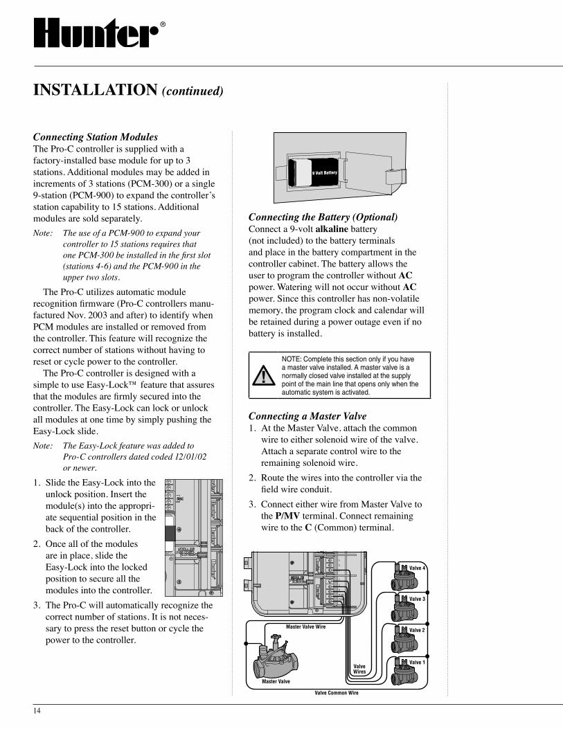
Connecting Station Modules The Pro-C controller is supplied with a factory-installed base module for up to 3 stations. Additional modules may be added in increments of 3 stations (PCM-300) or a single 9-station (PCM-900) to expand the controllerʼs station capability to 15 stations. Additional modules are sold separately.Note: The use of a PCM-900 to expand your
controller to 15 stations requires that one PCM-300 be installed in the first slot (stations 4-6) and the PCM-900 in the upper two slots.
The Pro-C utilizes automatic module recognition firmware (Pro-C controllers manu-factured Nov. 2003 and after) to identify when PCM modules are installed or removed from the controller. This feature will recognize the correct number of stations without having to reset or cycle power to the controller.
The Pro-C controller is designed with a simple to use Easy-Lock™ feature that assures that the modules are firmly secured into the controller. The Easy-Lock can lock or unlock all modules at one time by simply pushing the Easy-Lock slide.Note: The Easy-Lock feature was added to
Pro-C controllers dated coded 12/01/02 or newer.
1. Slide the Easy-Lock into the unlock position. Insert the module(s) into the appropri-ate sequential position in the back of the controller.
2. Once all of the modules are in place, slide the Easy-Lock into the locked position to secure all the modules into the controller.
3. The Pro-C will automatically recognize the correct number of stations. It is not neces-sary to press the reset button or cycle the power to the controller.
Connecting the Battery (Optional) Connect a 9-volt alkaline battery (not included) to the battery terminals and place in the battery compartment in the controller cabinet. The battery allows the user to program the controller without AC power. Watering will not occur without AC power. Since this controller has non-volatile memory, the program clock and calendar will be retained during a power outage even if no battery is installed.
NOTE: Complete this section only if you have a master valve installed. A master valve is a normally closed valve installed at the supply point of the main line that opens only when the automatic system is activated.
Connecting a Master Valve 1. At the Master Valve, attach the common
wire to either solenoid wire of the valve. Attach a separate control wire to the remaining solenoid wire.
2. Route the wires into the controller via the field wire conduit.
3. Connect either wire from Master Valve to the P/MV terminal. Connect remaining wire to the C (Common) terminal.
INSTALLATION (continued)
9 Volt Battery
Valve Common Wire
Valve 1
Valve 2
Valve 3
Valve 4
ValveWires
Master Valve
Master Valve Wire
15
Pro-C Controller
Sensor Wire to SEN
Mini-Clik®
Weather Sensor
Sensor Wire to SEN
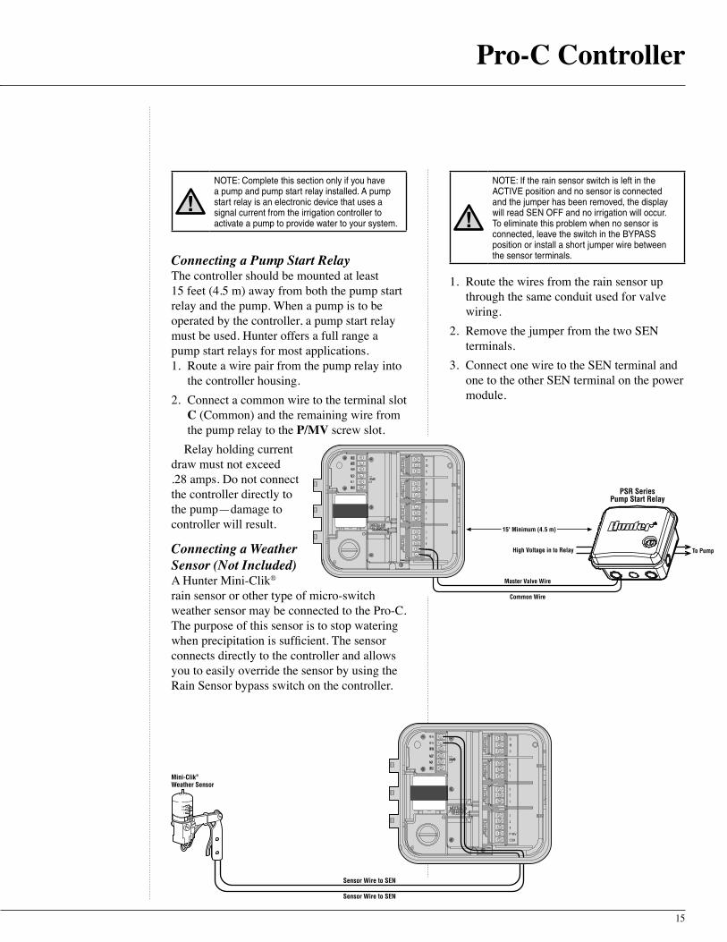
NOTE: Complete this section only if you have a pump and pump start relay installed. A pump start relay is an electronic device that uses a signal current from the irrigation controller to activate a pump to provide water to your system.
Connecting a Pump Start Relay The controller should be mounted at least 15 feet (4.5 m) away from both the pump start relay and the pump. When a pump is to be operated by the controller, a pump start relay must be used. Hunter offers a full range a pump start relays for most applications.1. Route a wire pair from the pump relay into
the controller housing.2. Connect a common wire to the terminal slot
C (Common) and the remaining wire from the pump relay to the P/MV screw slot.
Relay holding current draw must not exceed .28 amps. Do not connect the controller directly to the pump—damage to controller will result.
Connecting a Weather Sensor (Not Included) A Hunter Mini-Clik® rain sensor or other type of micro-switch weather sensor may be connected to the Pro-C. The purpose of this sensor is to stop watering when precipitation is sufficient. The sensor connects directly to the controller and allows you to easily override the sensor by using the Rain Sensor bypass switch on the controller.
Common Wire
Master Valve Wire
PSR SeriesPump Start Relay
To Pump
15' Minimum (4.5 m)
High Voltage in to Relay
NOTE: If the rain sensor switch is left in the ACTIVE position and no sensor is connected and the jumper has been removed, the display will read SEN OFF and no irrigation will occur. To eliminate this problem when no sensor is connected, leave the switch in the BYPASS position or install a short jumper wire between the sensor terminals.
1. Route the wires from the rain sensor up through the same conduit used for valve wiring.
2. Remove the jumper from the two SEN terminals.
3. Connect one wire to the SEN terminal and one to the other SEN terminal on the power module.
16
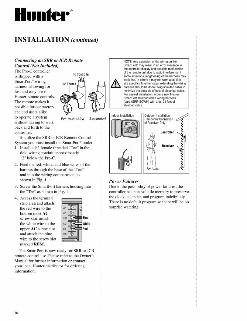
Connecting an SRR or ICR Remote Control (Not Included) The Pro-C controller is shipped with a SmartPort® wiring harness, allowing for fast and easy use of Hunter remote controls. The remote makes it possible for contractors and end users alike to operate a system without having to walk back and forth to the controller.
To utilize the SRR or ICR Remote Control System you must install the SmartPort® outlet.1. Install a ½" female threaded “Tee” in the
field wiring conduit approximately 12" below the Pro-C.
2. Feed the red, white, and blue wires of the harness through the base of the “Tee” and into the wiring compartment as shown in Fig. 1.
3. Screw the SmartPort harness housing into the “Tee” as shown in Fig. 1.
4. Access the terminal strip area and attach the red wire to the bottom most AC screw slot, attach the white wire to the upper AC screw slot and attach the blue wire to the screw slot marked REM.
The SmartPort is now ready for SRR or ICR remote control use. Please refer to the Ownerʼs Manual for further information or contact your local Hunter distributor for ordering information.
INSTALLATION (continued)
1/2" Thread
To Controller
Pre-assembled AssembledPre-assembled Assembled
Red
Blue
White
NOTE: Any extension of the wiring on the SmartPort® may result in an error message in the controller display and possible malfunction of the remote unit due to radio interference. In some situations, lengthening of the harness may work fine, in others it may not work at all (it is site specific). In either case, extending the wiring harness should be done using shielded cable to minimize the possible effects of electrical noise. For easiest installation, order a new Hunter SmartPort shielded cable wiring harness (part #SRR-SCWH) with a full 25 feet of shielded cable.
Power Failures Due to the possibility of power failures, the controller has non-volatile memory to preserve the clock, calendar, and program indefinitely. There is no default program so there will be no surprise watering.
Controller
Receiver
Outdoor Installation(Temporary Connectionof Receiver Only)
Indoor Installation
17
Pro-C Controller
PROGRAMMING
Programming the Controller Two key features of the Pro-C that make programming a snap are its clear, easy-to-read LCD display and its easy-to-use dial design.
The Pro-C display shows time and day when the controller is idle. The display changes when the dial is rotated to indicate the specific programming information to enter. When programming, the flashing portion of the display can be changed by pressing the
or buttons. To change something that is not flashing, press or until desired field is flashing.
The Pro-C controller offers maximum scheduling flexibility including three programs, each with up to 4 daily start times, permitting plants with different watering requirements to be separated on different day schedules. Multiple start times permit morning, afternoon and evening watering, perfect for the establishment of new lawns and thirsty annual flowers. A built in 365-day calendar clock accommodates odd/even watering restrictions without requiring monthly reprogramming. Or, just simply designate the days of the week you want to water or use the convenient day interval watering.
NOTE: A basic programming rule is that whatever symbol or character is flashing will be the item programmed. For instance, if the hour is flashing when setting the time, the hour can be changed or programmed. For illustration purposes, flashing characters are in Gray type.
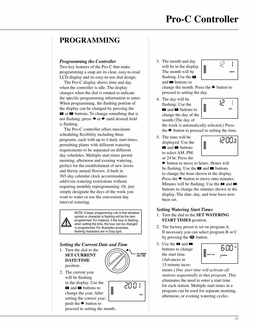
Setting the Current Date and Time 1. Turn the dial to the
SET CURRENT DATE/TIME position.
2. The current year will be flashing in the display. Use the
and buttons to change the year. After setting the correct year, push the button to proceed to setting the month.
SET CURRENTDATE / TIME
3. The month and day will be in the display. The month will be flashing. Use the and buttons to change the month. Press the button to proceed to setting the day.
4. The day will be flashing: Use the
and buttons to change the day of the month (The day of the week is automatically selected.) Press the button to proceed to setting the time.
5. The time will be displayed: Use the
and buttons to select AM, PM, or 24 hr. Press the
button to move to hours. Hours will be flashing. Use the and buttons to change the hour shown in the display. Press the button to move onto minutes. Minutes will be flashing. Use the and buttons to change the minutes shown in the display. The date, day, and time have now been set.
Setting Watering Start Times 1. Turn the dial to the SET WATERING
START TIMES position.2. The factory preset is set on program A.
If necessary you can select program B or C by pressing the button.
3. Use the and buttons to change the start time. (Advances in 15-minute incre-ments.) One start time will activate all stations sequentially in that program. This eliminates the need to enter a start time for each station. Multiple start times in a program can be used for separate morning, afternoon, or evening watering cycles.

18
4. Turn the dial to SET STATION RUN TIMES to continue programming the selected program.
5. Press the button to add an additional start time, or for the next program.
NOTE: Regardless of the order in which the start times are entered, the Pro-C will always arrange the start times in chronological order when the dial is moved off the SET WATERING START TIMES position.
Eliminating a Program Start Time With the dial set to the SET WATERING START TIMES position, push the and buttons until you reach 12:00 a.m. (Midnight). From this position push the button once to reach the OFF position.
NOTE: If a program has all four start times turned off, then that program is off (all other program details are retained). Because there are no start times, there will be no watering with that program. This is a convenient way to stop watering on one program only without turning the dial to the off position.
Setting Station Run Times (Length of Watering for Each Area) 1. Turn the dial to the
SET STATION RUN TIMES position.
2. The display will show the last program selected (A, B, or C) the station number selected, and the run time for that station will be flashing. You can switch to another program by pressing the button.
3. Use the and buttons to change the station run time on the display.
4. Press the button to advance to the next station.
5. Repeat steps 4 and 5 for each station.
PROGRAMMING (continued)
SETWATERINGSTARTTIMES
SET STATION RUN TIMES
6. You may set station run times from 1 minute to 6 hours.
7. You can move between programs while staying on the same station. However, it is recommended that one program is completed before going on to the next program. Jumping between programs can be confusing and may result in program errors.
Setting Days to Water 1. Turn the dial to the
SET DAYS TO WATER position.
2. The display will show the last program selected (A, B, or C) the station number selected, and the run time for that station will be flashing. You can switch to another program by pressing the button.
3. The controller displays currently programmed active day schedule informa-tion. This dial position provides four different water day options: choose to water on specific days of the week, you can choose interval watering, or choose to water on odd days or even days. Each program can only operate using one type of water day option.
SET DAYS TO WATER

19
Pro-C Controller
Selecting Specific Days of the Week to Water 1. Press the Press the
button to activate a particular day of the week to water (the display always starts with Monday). Press the button to cancel watering for that day. After pressing a button the display automatically advances to the next day. A indicates a water day. A indicates a no water day.
2. Repeat step 1 until desired days have been selected.
After programming, set dial to RUN to enable automatic execution of all selected programs and start times.
Selecting Interval Watering This feature is convenient if you want to have a more consistent watering schedule without having to worry about the day of the week or the date. The interval you select is the amount of days between watering. The days remaining indicates how many days until the next watering. For example if you select an interval of 2 with 1 days remaining, watering will begin tomorrow at the scheduled time. 1. With the cursor on
Sunday, press the button. Interval days left, Odd and Even will appear in the display.
2. Interval is flashing press the button. The display will increment the interval.
3. Press , the number of days will be flashing. Use the
and buttons to select the number of days left until the next watering.
After programming, set dial to RUN to enable automatic execution of all selected programs and start times.
Selecting Odd or Even Days to Water This feature uses a numbered day of the month for watering instead of specific days of the week (odd days 1st, 3rd, 5th, etc.; even days 2nd, 4th, 6th, etc.).1. Using the instructions for Interval
Watering, set the interval to one.2. Press the button
until the cursor is on either EVEN or ODD in the display. Select whichever you choose as No Water Days. If you select ODD as No Water Days,then the controller will only water on even days of the month. Conversely, if you select EVEN as No Water Days then the controller will only water on odd days of the month.
NOTE: The 31st of any month and February 29th are always “off” days if Odd watering is selected.
After programming, set dial to RUN to enable automatic execution of all selected programs and start times.
Weather Sensor Bypass With this built-in feature,
there is no need for an additional manual bypass switch when using rain sensors (the Pro-C works with the
Hunter Mini-Clik®, plus some other rain, wind, and freeze sensors on the market today). If the system is preventing system operation (or no sensor is installed and the switch is in the ACTIVE position), SENSOR OFF will be displayed. Simply move the switch to BYPASS and the weather sensor will be bypassed. This allows you to use the system.
RAIN SENSORBYPASS
ACTIVE
SYSTEM
20
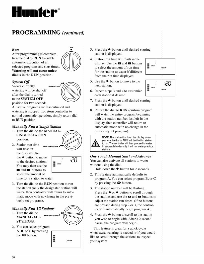
Run After programming is complete, turn the dial to RUN to enable automatic execution of all selected programs and start times. Watering will not occur unless dial is in the RUN position.
System Off Valves currently watering will be shut off after the dial is turned to the SYSTEM OFF position for two seconds. All active programs are discontinued and watering is stopped. To return controller to normal automatic operation, simply return dial to RUN position.
Manually Run a Single Station 1. Turn the dial to the MANUAL-
SINGLE STATION position.
2. Station run time will flash in the display. Use the button to move to the desired station. You may then use the
and buttons to select the amount of time for a station to water.
3. Turn the dial to the RUN position to run the station (only the designated station will water, then controller will return to auto-matic mode with no change in the previ-ously set program).
Manually Run All Stations 1. Turn the dial to
MANUAL-ALL STATIONS.
2. You can select program A, B, or C by pressing the button.
PROGRAMMING (continued)
RUN
SYSTEM OFF
MANUAL – SINGLE STATION
MANUAL – ALL STATIONS
3. Press the button until desired starting station is displayed.
4. Station run time will flash in the display. Use the and buttons to select the amount of run time for the station to water if different from the run time displayed.
5. Use the button to move to the next station.
6. Repeat steps 3 and 4 to customize each station if desired.
7. Press the button until desired starting station is displayed.
8. Return the dial to RUN (custom program will water the entire program beginning with the station number last left in the display, then controller will return to automatic mode with no change in the previously set program).
NOTE: The station that is on the display when you turn the dial to RUN, will be the first station to run. The controller will then proceed to water in sequential order only. It will not water previous stations.
One Touch Manual Start and Advance You can also activate all stations to water without using the dial.1. Hold down the button for 2 seconds. 2. This feature automatically defaults to
program A. You can select program B, or C by pressing the button.
3. The station number will be flashing. Press the or button to scroll through the stations and use the and buttons to adjust the station run times. (If no buttons are pressed during step 2 or 3, the control-ler will automatically begin program A.)
4. Press the button to scroll to the station you wish to begin with. After a 2 second pause, the program will begin.
This feature is great for a quick cycle when extra watering is needed or if you would like to scroll through the stations to inspect your system.
21
Pro-C Controller
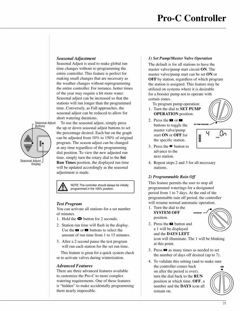
Seasonal Adjustment Seasonal Adjust is used to make global run time changes without re-programming the entire controller. This feature is perfect for making small changes that are necessary as the weather changes without reprogramming the entire controller. For instance, hotter times of the year may require a bit more water. Seasonal adjust can be increased so that the stations will run longer than the programmed time. Conversely, as Fall approaches, the seasonal adjust can be reduced to allow for short watering durations.
To use the seasonal adjust, simply press the up or down seasonal adjust buttons to set the percentage desired. Each bar on the graph can be adjusted from 10% to 150% of original program. The season adjust can be changed at any time regardless of the programming dial position. To view the new adjusted run time, simply turn the rotary dial to the Set Run Times position, the displayed run time will be updated accordingly as the seasonal adjustment is made.
NOTE: The controller should always be initially programmed in the 100% position.
Test Program You can activate all stations for a set number of minutes.1. Hold the button for 2 seconds.2. Station run time will flash in the display.
Use the or buttons to select the amount of run time from 1 to 15 minutes.
3. After a 2 second pause the test program will run each station for the set run time.
This feature is great for a quick system check or to activate valves during winterization.
Advanced Features There are three advanced features available to customize the Pro-C to more complex watering requirements. One of these features is “hidden” to make accidentally programming them nearly impossible.
Seasonal AdjustButtons
Seasonal AdjustDisplay
1) Set Pump/Master Valve OperationThe default is for all stations to have the master valve/pump start circuit ON. The master valve/pump start can be set ON or OFF by station, regardless of which program the station is assigned. This feature may be utilized on systems where it is desirable for a booster pump not to operate with certain zones.
To program pump operation:1. Turn the dial to SET PUMP
OPERATION position.2. Press the or
buttons to toggle the master valve/pump start ON or OFF for the specific station.
3. Press the button to advance to the next station.
4. Repeat steps 2 and 3 for all necessary stations.
2) Programmable Rain OffThis feature permits the user to stop all programmed waterings for a designated period from 1 to 7 days. At the end of the programmable rain off period, the controller will resume normal automatic operation.1. Turn the dial to the
SYSTEM OFF position.
2. Press the button and a 1 will be displayed and the DAYS LEFT icon will illuminate. The 1 will be blinking at this point.
3. Press as many times as needed to set the number of days off desired (up to 7).
4. To validate this setting (and to make sure the controller comes back on after the period is over), turn the dial back to the RUN position at which time, OFF, a number and the DAYS icon all remain on.
SET PUMP OPERATION
RUN
SYSTEM OFF
22
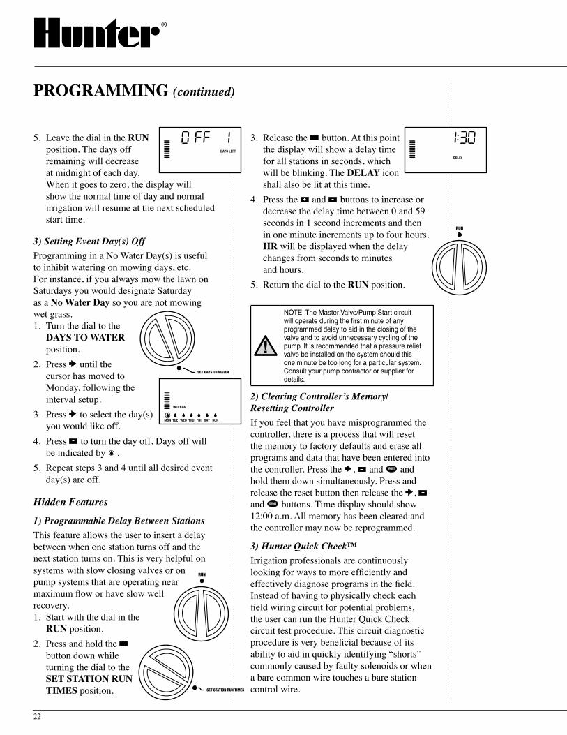
5. Leave the dial in the RUN position. The days off remaining will decrease at midnight of each day. When it goes to zero, the display will show the normal time of day and normal irrigation will resume at the next scheduled start time.
3) Setting Event Day(s) OffProgramming in a No Water Day(s) is useful to inhibit watering on mowing days, etc. For instance, if you always mow the lawn on Saturdays you would designate Saturday as a No Water Day so you are not mowing wet grass. 1. Turn the dial to the
DAYS TO WATER position.
2. Press until the cursor has moved to Monday, following the interval setup.
3. Press to select the day(s) you would like off.
4. Press to turn the day off. Days off will be indicated by .
5. Repeat steps 3 and 4 until all desired event day(s) are off.
Hidden Features
1) Programmable Delay Between StationsThis feature allows the user to insert a delay between when one station turns off and the next station turns on. This is very helpful on systems with slow closing valves or on pump systems that are operating near maximum flow or have slow well recovery.1. Start with the dial in the
RUN position.2. Press and hold the
button down while turning the dial to the SET STATION RUN TIMES position.
PROGRAMMING (continued)
SET DAYS TO WATER
3. Release the button. At this point the display will show a delay time for all stations in seconds, which will be blinking. The DELAY icon shall also be lit at this time.
4. Press the and buttons to increase or decrease the delay time between 0 and 59 seconds in 1 second increments and then in one minute increments up to four hours. HR will be displayed when the delay changes from seconds to minutes and hours.
5. Return the dial to the RUN position.
NOTE: The Master Valve/Pump Start circuit will operate during the first minute of any programmed delay to aid in the closing of the valve and to avoid unnecessary cycling of the pump. It is recommended that a pressure relief valve be installed on the system should this one minute be too long for a particular system. Consult your pump contractor or supplier for details.
2) Clearing Controller s̓ Memory/ Resetting ControllerIf you feel that you have misprogrammed the controller, there is a process that will reset the memory to factory defaults and erase all programs and data that have been entered into the controller. Press the , and and hold them down simultaneously. Press and release the reset button then release the , and buttons. Time display should show 12:00 a.m. All memory has been cleared and the controller may now be reprogrammed.
3) Hunter Quick Check™
Irrigation professionals are continuously looking for ways to more efficiently and effectively diagnose programs in the field. Instead of having to physically check each field wiring circuit for potential problems, the user can run the Hunter Quick Check circuit test procedure. This circuit diagnostic procedure is very beneficial because of its ability to aid in quickly identifying “shorts” commonly caused by faulty solenoids or when a bare common wire touches a bare station control wire.
RUN
RUN
SET STATION RUN TIMES

23
Pro-C Controller
PROBLEM CAUSES SOLUTIONS
There is no display. Check AC power wiring. Correct any errors.
The display reads "ERR". Electrical noise is entering the system. Check the SmartPort® wiring harness. If the wires were extended then they will need to be replaced with shielded cable. Contact your local distributor for information on shielded cable.
The display reads "P ERR". There is a ground fault in the wire to the pump start or master valve.
Check the master valve or pump start wire for continuity. Replace or repair the broken wire. Check that all wire connections are good and water tight.
The display reads a station number and ERR, such as "2 ERR".
There has been a ground fault with the wire leading to that station.
Check the station wire for continuity. Replace or repair broken wire. Check that all wire connections are good and water tight.
The display reads "NO AC". There is no AC power present. Check to see if the transformer is properly installed.
The display reads "SENSOR OFF". The rain sensor is interrupting irrigation or not installed.
Slide the Rain Sensor switch on front panel to the BYPASS position to bypass rain sensor circuit.
Rain sensor will not shut off system. Make sure sensor is micro-switch type such as Mini-Clik®. Rain Bird®, Rain Check™ is not this type and will not work. Check that the the jumper has been removed from the SEN terminals.
The controller recognizes 15 stations all the time.
Make sure AC power is connected. Reset controller using method described on page 24.
The controller does not respond to all stations. Example, the controller has 12 stations but the display will only go to 6 stations.
Controller does not recognize modules. Turn off the power to the controller and remove the battery. Check all module connections to the controller. Power the controller back up. The microprocessor will recognize all modules.
TROUBLESHOOTING GUIDE
To initiate the Hunter Quick Check test procedure; Press the , , and buttons simultaneously. In the standby mode, the LCD will display all segments (helpful when troubleshooting display problems). Press the button to begin the Quick Check test procedure. Within seconds, the system searches all stations in an effort to detect a high current path through the station terminals.
When a field wiring short is detected, an ERR symbol preceded by the station number will momentarily flash on the controller LCD display. After the Hunter Quick Check completes running this circuit diagnostic procedure, the controller returns to the automatic watering mode.

24
®
PRODUCT OVERVIEW
Hunter is pleased to introduce the SRR – a Simple and Reliable Remote Control for use with our Pro-C, ICC and SRC controllers. The SRR can offer the installer features that other remotes canʼt, at a price that canʼt be beat.
How often does a contractor have to walk back to the controller to start or stop a manual watering cycle when doing new installa-tion or maintenance on a landscape project? How difficult and costly is it to winterized an irrigation system with two workers instead of one? How time consuming is it to keep returning to the controller to start or stop a manual cycle?
Now itʼs no trouble at all, with the Hunter SRR! Plus, the contractor can leave the SRR remote with the property owner, allowing the homeowner or building manager to remotely activate a manual watering without the need to visit the controller. The SRR is the simplest, most reliable remote control available.
One Transmitter, One Receiver Does the Job Portable and reusable at every locationWith the SRR, a contractor can visit one site, attach the receiver to the SmartPort® wire harness at the controller, complete the irrigation operations, remove the receiver and travel on to the next job. Or the receiver can be left permanently mounted, if desired, to permit operation by the homeowner or building manager.
Internal Antenna on Transmitter Out of sight, out of mindThe SRRʼs transmitter has no external antenna that can be broken or lost.
Large LCD Display and Four-Button Operation Easy to view and a snap to operateSimply press the and buttons to display the station or program that is desired, then press the “ON” or “OFF” buttons. After several minutes of inactivity, the SRR turns itself off to extend battery life. It can be reactivated by touching any button.
Sturdy ABS Construction Tough and rugged for any userThe SRR transmitter and receiver are made of heavy-duty ABS plastic that will withstand the toughest conditions and repeat uses.
PRODUCT FEATURES AND BENEFITS
25
SRR Remote Control
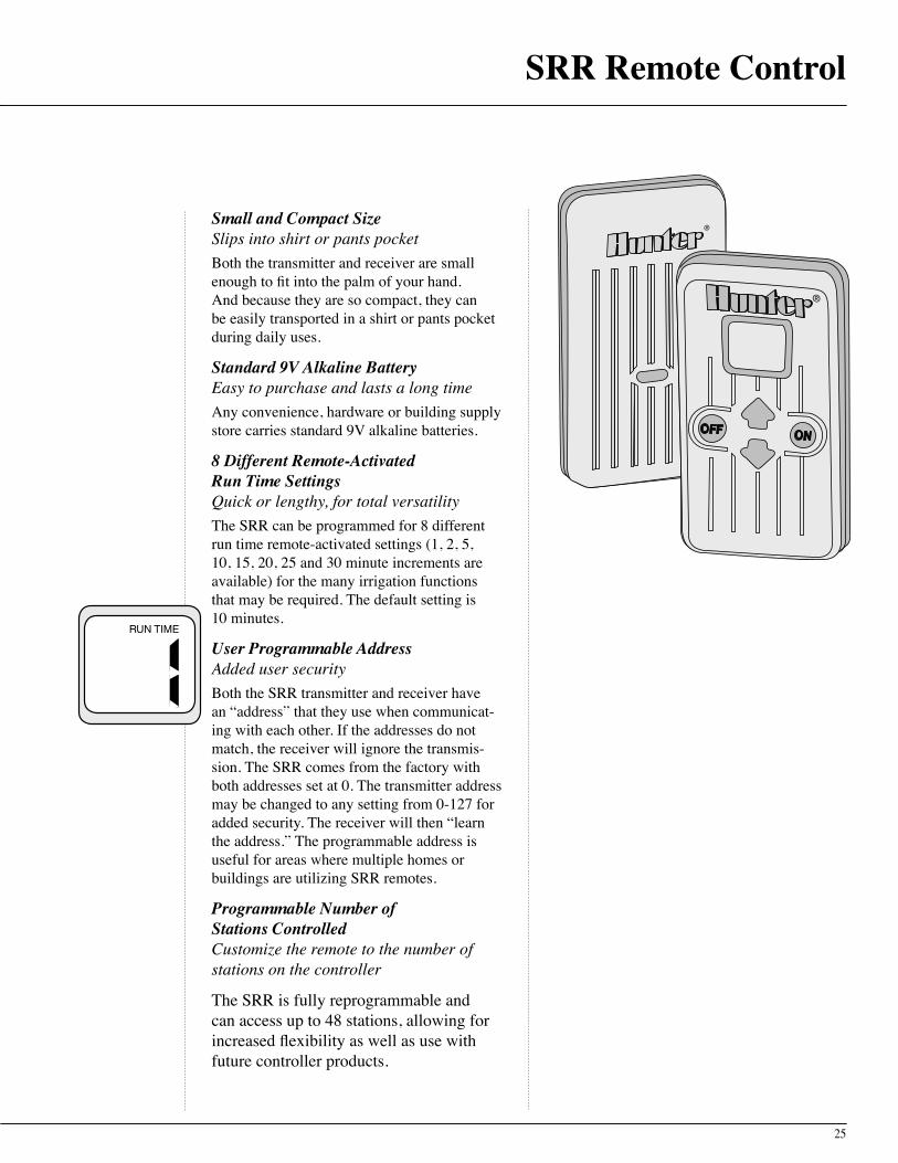
Small and Compact SizeSlips into shirt or pants pocketBoth the transmitter and receiver are small enough to fit into the palm of your hand. And because they are so compact, they can be easily transported in a shirt or pants pocket during daily uses.
Standard 9V Alkaline Battery Easy to purchase and lasts a long timeAny convenience, hardware or building supply store carries standard 9V alkaline batteries.
8 Different Remote-Activated Run Time Settings Quick or lengthy, for total versatilityThe SRR can be programmed for 8 different run time remote-activated settings (1, 2, 5, 10, 15, 20, 25 and 30 minute increments are available) for the many irrigation functions that may be required. The default setting is 10 minutes.
User Programmable Address Added user securityBoth the SRR transmitter and receiver have an “address” that they use when communicat-ing with each other. If the addresses do not match, the receiver will ignore the transmis-sion. The SRR comes from the factory with both addresses set at 0. The transmitter address may be changed to any setting from 0-127 for added security. The receiver will then “learn the address.” The programmable address is useful for areas where multiple homes or buildings are utilizing SRR remotes.
Programmable Number of Stations Controlled Customize the remote to the number of stations on the controller
The SRR is fully reprogrammable and can access up to 48 stations, allowing for increased flexibility as well as use with future controller products.
RUN TIME

26
SmartPort® Wiring Harness Preparing the Communication PortTo utilize the SRR Remote Control System, your Hunter controller must be equipped with the SRR SmartPort wiring harness. This wiring harness provides the communica-tion port where the SRR receiver is attached. The SmartPort installation instructions are included in the Pro-C installation and programming instructions. Additional wiring harnesses can be purchased separately to allow you to utilize the transmitter and receiver with additional controllers.
Installing the SRR Remote Wiring Harness 1) Install a ½" female threaded “Tee” in
the field wiring conduit approximately 12" below the Pro-C controller.
Note: The harness may be installed outdoors by first bringing the conduit through an exterior wall, then installing the appropriate fitting.
2) Feed the red, white and blue wires of the harness through the base of the “Tee” and into the controller wiring compartment as shown in Figure 1.
3) Screw the harness housing into the “Tee” (or other fitting) as shown in Figure 1.
INSTALLATION AND PROGRAMMING
Fig. 1
To Controller
½" Thread
Pre-assembled Wiring Harness
4) Attach the red, white and blue wires from the harness to the terminal block of the controller as shown in Figure 2.
Extending the Wiring Harness Any extension of the wiring on the harness may result in an error message in the controller display and possible malfunction of the remote unit due to radio interference. In some situations, lengthening of the harness may work fine, in others it may not work at all (it is site specific). In either case, extending the wiring harness should be done using shielded cable (Radio Shack P/N 278-513) to minimize the possible effects of electrical noise. See diagram below.
Proper Extension of Wiring Harness Using Shielded Cable
Transmitter
Preparing the Transmitter for UseYour SRR System is designed to work right out of the box. This means that other than installing the battery, you may chose to skip this entire section. However, we recommend you read it because with a few simple steps you can customize your SRR to add function-ality and security to your system. Be aware that if you change your transmitter address or maximum station number as described below, you should make a note of the new settings, since when the battery is removed and a new one installed, the transmitter will revert back to the original settings.
Fig. 2
Red
Blue
White
RADIO SHACK SHIELDEDCABLE PN 278-513
PRO-C TERMINAL BLOCK
GRD AC1 AC2 REM SEN SEN

27
SRR Remote Control
Installing the Transmitter BatteryYour SRR Transmitter requires a 9V alkaline battery. To install the battery, slide open the battery door (on the back of the transmitter), attach the battery to the clip, insert the battery, and slide the door shut again. (When changing the battery, push the battery down in the case to reveal the battery clip before attempting to remove the battery from the case.)
Changing the Transmitter AddressBoth the SRR Transmitter and Receiver have an “address” that they use when communicating. If the addresses do not match, the Receiver will ignore the transmission. Your SRR comes from the factory with both Transmitter and Receiver address set to 0. You may change the address to any value from 0-127 for added security. Note that if you change the Transmitter address, the Receiver must “learn” the new address as described in “Preparing the Receiver for Use” section.
To change the Transmitter address follow the steps below:1. If the unit is OFF (no display), power
the Transmitter by pressing any of the buttons for at least 1 second then releasing the button. The Transmitter will first illuminate the entire display for 1 second then display the active station.
2. Simultaneously press the and buttons, until the word “RUN TIME” along with the current Run Time is displayed. The display will be blinking at this point.
3. While the display is blinking and show-ing the current Run Time, Press the “ON” button. The word “ADDRESS” will now illuminate and the current address will be blinking. Note that if more than 5 seconds go by without a button being pressed, the Transmitter will revert back to displaying the active station.
4. Use the and buttons to change the address to any value between 0 and 127. Then do not touch any of the buttons for 5 seconds and the display will stop blinking, and return back to the active station.
Receiver Preparing the Receiver for UseAs stated earlier, your SRR System is designed to work right out of the box. If you have decided to change your Transmitter address as described in the previous section, you must allow the Receiver to “learn” this new address. Once learned, the only way to remove the address from Receiver memory is to learn a different address. This can be done by following the simple steps outlined below.
Changing the Receiver Address1. Hold down the single button on the
face of your Receiver while you are plugging it into an active wiring harness (one connected to a powered controller). When this is done, the Receiver will beep 4 times.
2. After the Receiver starts to beep, release the button.
3. Press either the “ON” or “OFF” button of your Transmitter.
4. The Receiver will beep 4 additional times indicating that it has learned the new Transmitter address and will respond only to it from this point on.
RUN TIME
28
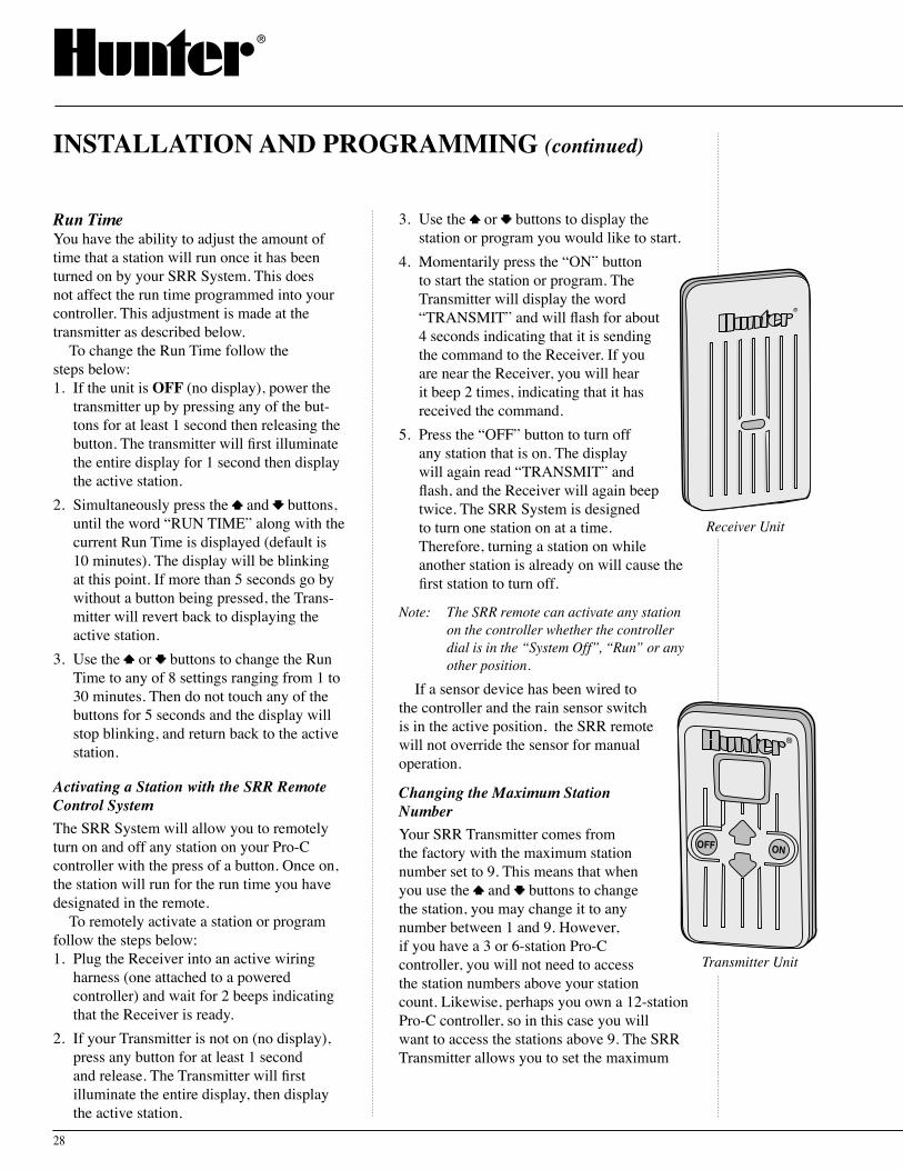
Run Time You have the ability to adjust the amount of time that a station will run once it has been turned on by your SRR System. This does not affect the run time programmed into your controller. This adjustment is made at the transmitter as described below.
To change the Run Time follow the steps below:1. If the unit is OFF (no display), power the
transmitter up by pressing any of the but-tons for at least 1 second then releasing the button. The transmitter will first illuminate the entire display for 1 second then display the active station.
2. Simultaneously press the and buttons, until the word “RUN TIME” along with the current Run Time is displayed (default is 10 minutes). The display will be blinking at this point. If more than 5 seconds go by without a button being pressed, the Trans-mitter will revert back to displaying the active station.
3. Use the or buttons to change the Run Time to any of 8 settings ranging from 1 to 30 minutes. Then do not touch any of the buttons for 5 seconds and the display will stop blinking, and return back to the active station.
Activating a Station with the SRR Remote Control SystemThe SRR System will allow you to remotely turn on and off any station on your Pro-C controller with the press of a button. Once on, the station will run for the run time you have designated in the remote.
To remotely activate a station or program follow the steps below:1. Plug the Receiver into an active wiring
harness (one attached to a powered controller) and wait for 2 beeps indicating that the Receiver is ready.
2. If your Transmitter is not on (no display), press any button for at least 1 second and release. The Transmitter will first illuminate the entire display, then display the active station.
INSTALLATION AND PROGRAMMING (continued)
3. Use the or buttons to display the station or program you would like to start.
4. Momentarily press the “ON” button to start the station or program. The Transmitter will display the word “TRANSMIT” and will flash for about 4 seconds indicating that it is sending the command to the Receiver. If you are near the Receiver, you will hear it beep 2 times, indicating that it has received the command.
5. Press the “OFF” button to turn off any station that is on. The display will again read “TRANSMIT” and flash, and the Receiver will again beep twice. The SRR System is designed to turn one station on at a time. Therefore, turning a station on while another station is already on will cause the first station to turn off.
Note: The SRR remote can activate any station on the controller whether the controller dial is in the “System Off”, “Run” or any other position.
If a sensor device has been wired to the controller and the rain sensor switch is in the active position, the SRR remote will not override the sensor for manual operation.
Changing the Maximum Station NumberYour SRR Transmitter comes from the factory with the maximum station number set to 9. This means that when you use the and buttons to change the station, you may change it to any number between 1 and 9. However, if you have a 3 or 6-station Pro-C controller, you will not need to access the station numbers above your station count. Likewise, perhaps you own a 12-station Pro-C controller, so in this case you will want to access the stations above 9. The SRR Transmitter allows you to set the maximum
Transmitter Unit
Receiver Unit
29
SRR Remote Control
station number as follows: 1. If the unit is OFF (no display), power the
Transmitter up by pressing any of the buttons for at least 1 second then releasing the button. The Transmitter will first illuminate the entire display for 1 second then display the active station.
2. Simultaneously press the and buttons, until the word “RUN TIME” along with the current Run Time is displayed. The display will be blinking at this point.
3. While the display is blinking and showing the current address, press the “ON” button. The display will continue to blink, but the word “ADDRESS” will be illuminated.
4. Press the “ON” button again. The dis-play will continue to blink, but the word “ADDRESS” will no longer be illuminated.
5. Use the or buttons to change the maximum station number to the value you desire. Then, do not press any buttons for 5 seconds and the display will stop blinking and return to the active station number.
6. You may now change the active setting to the new maximum station value.
Maximizing Operating RangeThere are many factors which influence operating range. Listed below are a few things you can do to assure you are getting the maximum range possible. 1. Do not install the outlet of the wiring
harness (that the Receiver connects to) near large sources of metal such as power meters, water pipes, and aluminum siding.
2. Do not install the outlet of the wiring harness in a basement or underground location. The higher, the better.
3. For maximum range in all directions from the Receiver, the Receiver antenna should be pointed straight up (vertically). If the Receiver is mounted with its antenna oriented horizontally, reception will be very good if the Transmitter is on either side of the antenna, but very poor if it is
facing the end of the Receiver antenna.4. When operating the Transmitter, hold the
Transmitter as vertical as possible and turn and face the direction of the Receiver, even if it is several hundred feet away.
A Word About Range There are many claims being made about the range of various remote control systems, whether they be for auto alarms, garage doors, or irrigation systems for that matter. The published range for the SRR System is up to 450 feet. Most users will achieve this range or more, but a few may not. It is the attempt of this section to educate the user about those factors that influence operating range. We believe that we have achieved the maximum performance available on this frequency.
Here s̓ why The range of any remote control system is dependent on many factors. These include theterrain at a particular site, obstructions such as buildings and walls, the strength of the various interfering signals, the sensitivity of the Receiver, the ability of the Receiver to reject “unwanted” signals, and the strength of the Transmitter. Since it is impossible to control the obstructions, terrain at a site, and the strength of interfering signals, it is impossible to guarantee an operating range under all conditions. However, we have done everything under our control to maximize the operating range of this system.
The SRR Transmitter has been designed to transmit the maximum power allowed by the FCC. Furthermore, it has special circuitry to assure that this maximum output power is maintained until just before the battery goes dead. Other transmitters emit less and less power as the battery wears down. The Receiver employs a reception method far superior to that used in a typical garage door opener or auto alarm.
The SRR has been designed to give you simple, reliable operation for many years.
30
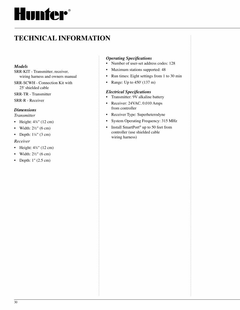
ModelsSRR-KIT - Transmitter, receiver,
wiring harness and owners manualSRR-SCWH - Connection Kit with
25' shielded cableSRR-TR - TransmitterSRR-R - Receiver
DimensionsTransmitter• Height: 4¾" (12 cm)• Width: 2½" (6 cm)• Depth: 1¼" (3 cm)
Receiver• Height: 4¾" (12 cm)• Width: 2½" (6 cm)• Depth: 1" (2.5 cm)
TECHNICAL INFORMATION
Operating Specifications• Number of user-set address codes: 128• Maximum stations supported: 48• Run times: Eight settings from 1 to 30 min• Range: Up to 450' (137 m)
Electrical Specifications• Transmitter: 9V alkaline battery• Receiver: 24VAC, 0.010 Amps
from controller• Receiver Type: Superheterodyne• System Operating Frequency: 315 MHz• Install SmartPort® up to 50 feet from
controller (use shielded cable wiring harness)


®
Hunter Industries Incorporated • The Irrigation Innovators © 2004 Hunter Industries Incorporated
1940 Diamond Street • San Marcos, California 92078www.HunterIndustries.com P/N 700757 LIT-325 10/04