
PRISON MANAGEMENT SYSTEM - …docshare01.docshare.tips/files/30541/305410878.pdfthis prison...
37
PRISON MANAGEMENT SYSTEM Department of Computer Sciences Submitted By: Muslim Mir (6029) Murad Ali (5993) Salman Karim (6028) M.Salman Khan (5995) Amir Muneeb (4854) BS-SE (5 th Semester) Sec-A Submitted To: Mr. Kashif Basir (Lecturer CS Department) City University of Science and Information Technology Peshawar 1
Transcript of PRISON MANAGEMENT SYSTEM - …docshare01.docshare.tips/files/30541/305410878.pdfthis prison...

PRISON MANAGEMENT SYSTEM
Department of Computer Sciences
Submitted By:
Muslim Mir (6029)
Murad Ali (5993)
Salman Karim (6028)
M.Salman Khan (5995)
Amir Muneeb (4854)
BS-SE (5th Semester) Sec-A
Submitted To: Mr. Kashif Basir (Lecturer CS Department)
City University of Science and Information TechnologyPeshawar
1
Table of ContentsVision and Scope Document.......................................................................................5
1. BUISSNESS REQUIRMENT:....................................................................................5
1.1 BACKGROUND:...............................................................................................5
1.2 BUISNESS OPPORTUNITY:...............................................................................5
1.3 BUISNESS OBJECTIVEES AND SUCCESS CRITERIA:.........................................5
1.4 CUSTOMER OR MARKET NEEDS:.....................................................................6
1.5 BUISNESS RISKS:............................................................................................6
2: VISION OF THE SOLUTION:..................................................................................7
2.1 VISION STATEMENT:........................................................................................7
2.2 MAJOR FEATURES:..........................................................................................7
2.3 ASSUMPTIONS & DEPENDENCIES:..................................................................8
3. SCOPE AND LIMITATION:......................................................................................8
3.1, 3.2 SCOPE OF INITIAL AND SUBSEQUENT RELEASE:......................................9
3.3 LIMITATION & EXCLUSION:..............................................................................9
4. BUISNESS CONTEXT:............................................................................................9
4.1 STAKE HOLDER PROFILES:............................................................................10
4.2 PROJECT PRIORITIES:....................................................................................10
4.3 OPPERATING ENVIRONMENT:........................................................................11
UML Diagrams..........................................................................................................12
Data Flow Diagram:...............................................................................................12
Level 0:..............................................................................................................12
Level 1:..............................................................................................................13
Level 2:..............................................................................................................14
Level 3:..............................................................................................................15
Level 4:..............................................................................................................15
Entity-Relationship Diagram:.................................................................................17
State Transition Diagram:......................................................................................18
Dialog Map:...........................................................................................................21
Class Diagram:......................................................................................................22
Decision Tables and Decision Trees:......................................................................24
2
Use Case Diagram:................................................................................................25
Activity Diagram:...................................................................................................27
Sequence Diagram:...............................................................................................29
Software Requirement Specification.........................................................................31
1. Introduction:....................................................................................................31
1.1 Purpose:.......................................................................................................31
1.2 Document Conventions:...............................................................................31
1.3 Intended Audience and Reading Suggestions:.............................................31
1.4 Project Scope:..............................................................................................31
1.5 Reference:....................................................................................................31
2. Overall Description:........................................................................................31
2.1 Product Perspective:.....................................................................................32
2.2 Product Features:.........................................................................................32
2.3 User Classes and Characteristics:................................................................32
2.4 Operating Environment:...............................................................................32
2.5 Design and Implementation Constraints:.....................................................32
2.6 User Documentation:...................................................................................33
2.7 Assumptions and Dependencies:.................................................................33
3 System Features:................................................................................................33
3. x System Feature X:.......................................................................................33
4 External Interface Requirements:.......................................................................34
4.1 User Interfaces:............................................................................................34
4.2 Hardware Interfaces:....................................................................................34
4.3 Software Interfaces:.....................................................................................35
4.4 Communication Interfaces:..........................................................................35
5 Other Nonfunctional Requirements:...................................................................35
5.1 Performance Requirements:.........................................................................35
5.2 Safety Requirements:...................................................................................36
5.3 Security Required:........................................................................................36
5.4 Software Quality Attributes:.........................................................................36
6 Other Requirements:..........................................................................................36
Appendix A: Glossary:............................................................................................36
Appendix B: Analysis Models:................................................................................36
3
Appendix C: Issues List:.........................................................................................37
Vision and Scope Document
4

1. BUISSNESS REQUIRMENT:To record the details of Prisoners and Jailors, policemen, cells, crime detailsetc.
1.1 BACKGROUND:At initial stage we had got a manual system .In which it was hard tosearch a single data of any prisoner, overwriting and time consuming,chance of data loss, too much space occupied because of too manyregisters which are present in hard form and it was non secure,because of these draw back we introduce a solution for it by building/constructing a software for the prison which keep all those records inefficient way. It will be easy to access no tendency problem, full secureand easily searchable.
1.2 BUISNESS OPPORTUNITY:It will be beneficial in a data loss case because we should have abackup system for it. It can be accessible from any prison .It has solvedour security, redundancy and searching process problems. It was notmuch space occupied like the previous system all the data will bestored in a single database system.
1.3 BUISNESS OBJECTIVEES AND SUCCESS CRITERIA:For the developers the major point of the success of product will be, tofulfill the needs and expectations of the customers and for the usersmajor point of success will be that it can be modifiable and itsperformance should be efficient.
BO-1: Reduce the loss of record by 90% so if we loss record sowe would have a backup system.
BO-2: To deliver a fully functional system that delivers close to100% efficiency in prisons management in a city.
BO-3: To bring in maximum accuracy in the prison managementin all key functional and operational areas; to overcomethe manual system in the process of remission
5
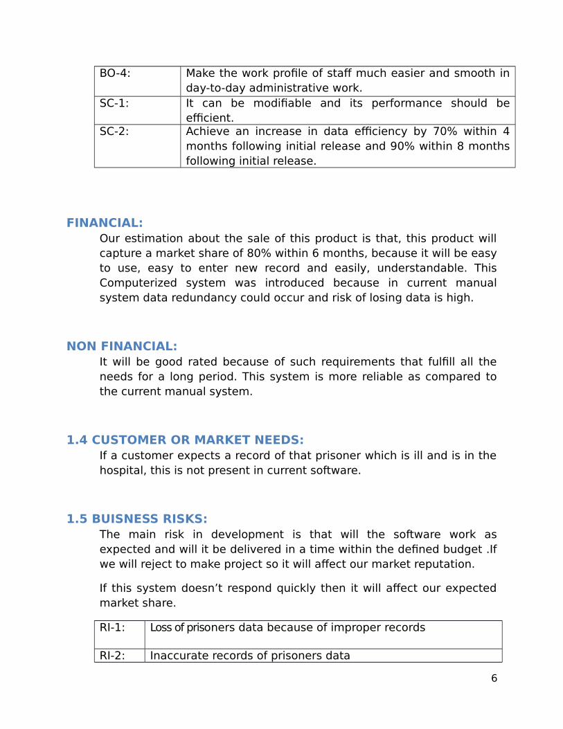
BO-4: Make the work profile of staff much easier and smooth inday-to-day administrative work.
SC-1: It can be modifiable and its performance should beefficient.
SC-2: Achieve an increase in data efficiency by 70% within 4months following initial release and 90% within 8 monthsfollowing initial release.
FINANCIAL:Our estimation about the sale of this product is that, this product willcapture a market share of 80% within 6 months, because it will be easyto use, easy to enter new record and easily, understandable. ThisComputerized system was introduced because in current manualsystem data redundancy could occur and risk of losing data is high.
NON FINANCIAL:It will be good rated because of such requirements that fulfill all theneeds for a long period. This system is more reliable as compared tothe current manual system.
1.4 CUSTOMER OR MARKET NEEDS:If a customer expects a record of that prisoner which is ill and is in thehospital, this is not present in current software.
1.5 BUISNESS RISKS:The main risk in development is that will the software work asexpected and will it be delivered in a time within the defined budget .Ifwe will reject to make project so it will affect our market reputation.
If this system doesn’t respond quickly then it will affect our expectedmarket share.
RI-1: Loss of prisoners data because of improper records
RI-2: Inaccurate records of prisoners data
6
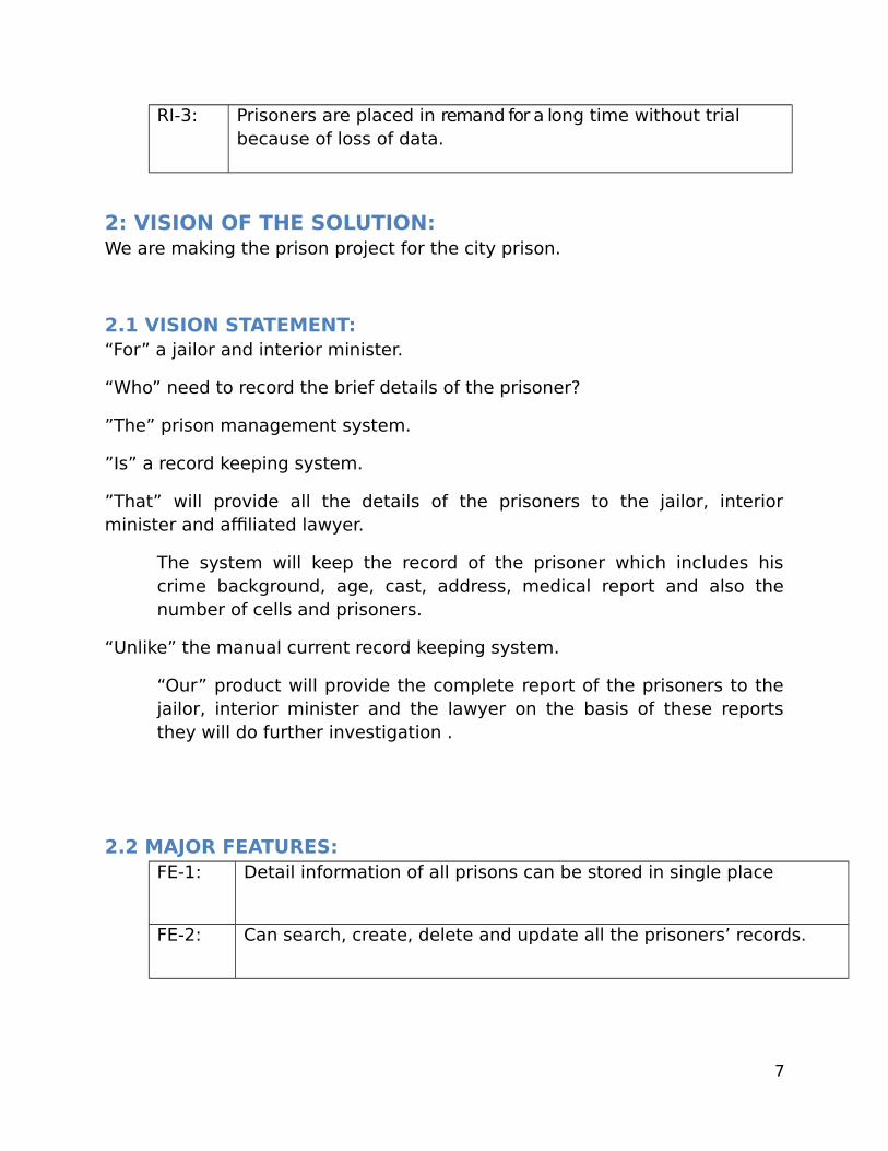
RI-3: Prisoners are placed in remand for a long time without trial because of loss of data.
2: VISION OF THE SOLUTION:We are making the prison project for the city prison.
2.1 VISION STATEMENT:“For” a jailor and interior minister.
“Who” need to record the brief details of the prisoner?
”The” prison management system.
”Is” a record keeping system.
”That” will provide all the details of the prisoners to the jailor, interiorminister and affiliated lawyer.
The system will keep the record of the prisoner which includes hiscrime background, age, cast, address, medical report and also thenumber of cells and prisoners.
“Unlike” the manual current record keeping system.
“Our” product will provide the complete report of the prisoners to thejailor, interior minister and the lawyer on the basis of these reportsthey will do further investigation .
2.2 MAJOR FEATURES:FE-1: Detail information of all prisons can be stored in single place
FE-2: Can search, create, delete and update all the prisoners’ records.
7

FE-3: Will use unique labels like astaric (*) to record the details of aprisoner as a functional requirement and access the record of theprisoners in the form of report as a user requirement.
FE-4: Daily basis Lock in/Lock up register.
FE-5: Daily base sick register.
FE-6: Tracking and monitoring facility for “Prison Death”, “Prison Escape” etc.
FE-7: Each prison will have their own interface with the facility to deal alldata related to them which can be access by their prison ID.
FE-8 Can search, delete, create and update all the jailors record.
2.3 ASSUMPTIONS & DEPENDENCIES:AS-1: With the prison management system the jailor may expect that he
want software along with a website.
AS-2: The jailor may want the medical report of the prisoner for the purposeof remand.
DE-1: As this system is for Government Organization, so the Customer maywant also NADRA System included.
3. SCOPE AND LIMITATION:It will keep the record of the prisoners i.e. the jailor, the police men andthe other employees working in the prison “Scope “ in the prisonmanagement system is that for the jailors it will record all the details ofthe prisoners ,lawyers can access the reports of the prisoners to do
8

further case. For the interior minister they can get all the details fromthis prison management system on one click if these are other requestfrom jailer out-of-scope then these request will be checked if theserequest or valuable ,they will be added otherwise rejected.
3.1, 3.2 SCOPE OF INITIAL AND SUBSEQUENT RELEASE:Feature Release 1 Release 2FE-1: The requirement like
Name, types ofcrime, age, address,location which arevery essential theyshould beimplemented at initialrelease.
Features like medicalreport of a prison arehard to add at initialrelease so we will add itnow.
FE-2: Not implemented Fully ImplementedFE-3: Prisoner’s details should be
given to the jailor andinterior minister.
Details should also be given tothe affiliated lawyers relatedto the different cases.
FE-4: To record the daily baseschedule of the policemenand provide the report tothe jailor on weekly base.
FE-5 To show the time table forfood of the prisoner’s.
FE-6 To provide weekly basemedical report and workingcredit hours of a prisoner’s in aprison.
3.3 LIMITATION & EXCLUSION:
LI-1: The features like prisoner details ,policemen, jailor, lawyerare present in the scope if a jailor wants a new features like
9
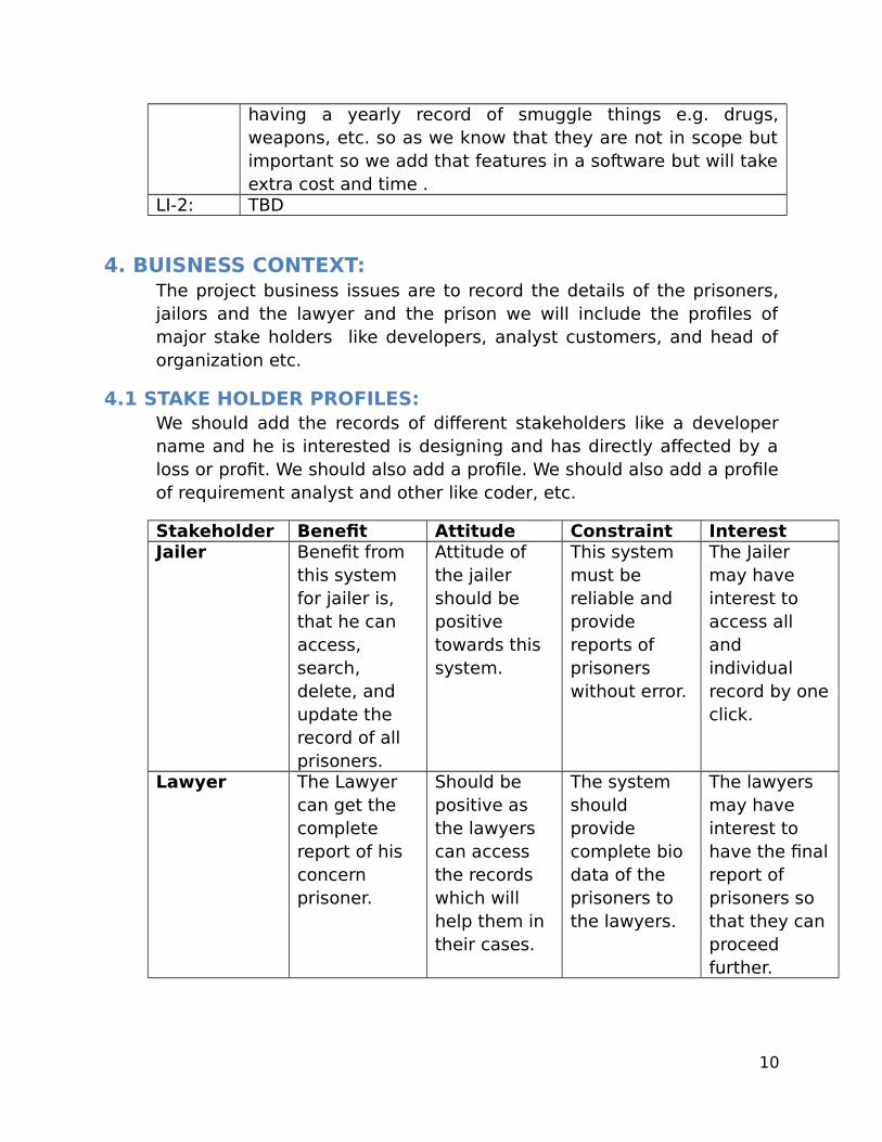
having a yearly record of smuggle things e.g. drugs,weapons, etc. so as we know that they are not in scope butimportant so we add that features in a software but will takeextra cost and time .
LI-2: TBD
4. BUISNESS CONTEXT:The project business issues are to record the details of the prisoners,jailors and the lawyer and the prison we will include the profiles ofmajor stake holders like developers, analyst customers, and head oforganization etc.
4.1 STAKE HOLDER PROFILES:We should add the records of different stakeholders like a developername and he is interested is designing and has directly affected by aloss or profit. We should also add a profile. We should also add a profileof requirement analyst and other like coder, etc.
Stakeholder Benefit Attitude Constraint InterestJailer Benefit from
this system for jailer is, that he can access, search, delete, and update the record of all prisoners.
Attitude of the jailer should be positive towards this system.
This system must be reliable and provide reports of prisoners without error.
The Jailer may have interest to access all and individual record by oneclick.
Lawyer The Lawyer can get the complete report of his concern prisoner.
Should be positive as the lawyers can access the records which will help them in their cases.
The system should provide complete bio data of the prisoners to the lawyers.
The lawyers may have interest to have the finalreport of prisoners so that they can proceed further.
10
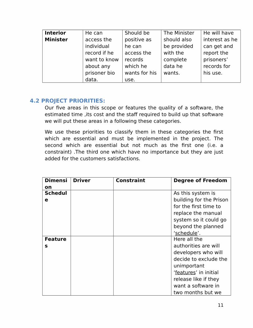
Interior Minister
He can access the individual record if he want to knowabout any prisoner bio data.
Should be positive as he can access the records which he wants for his use.
The Minister should also be provided with the complete data he wants.
He will have interest as hecan get and report the prisoners’ records for his use.
4.2 PROJECT PRIORITIES:Our five areas in this scope or features the quality of a software, theestimated time ,its cost and the staff required to build up that softwarewe will put these areas in a following these categories.
We use these priorities to classify them in these categories the firstwhich are essential and must be implemented in the project. Thesecond which are essential but not much as the first one (i.e. aconstraint) .The third one which have no importance but they are justadded for the customers satisfactions.
Dimension
Driver Constraint Degree of Freedom
Schedule
As this system is building for the Prisonfor the first time to replace the manual system so it could go beyond the planned ‘schedule’.
Features
Here all the authorities are will developers who will decide to exclude theunimportant ‘features’ in initial release like if they want a software in two months but we
11

will take much time.
Quality Features like report will be in a constraint, ‘quality’ must be taken in a constraint.
Staf We hire a ‘staff’ of 20 people instead of 10 to build a reliable anderror free system.
Cost If they demandfor the medicalreport of the prisoners .we will check it if it’s ‘cost’ is nottoo much expensive thenwe will implement that feature forhim.
4.3 OPPERATING ENVIRONMENT:The system will work only in the prison or in such area where rules andlow are enforced.
We will ask the stakeholders the following question i.e. Are the users ofthis system present in different cities of the country or in the same andhow many prisons of the country of different cities are connectedthrough this system?
12
UML Diagrams
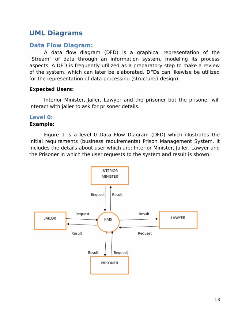
Data Flow Diagram:A data flow diagram (DFD) is a graphical representation of the
"Stream" of data through an information system, modeling its processaspects. A DFD is frequently utilized as a preparatory step to make a reviewof the system, which can later be elaborated. DFDs can likewise be utilizedfor the representation of data processing (structured design).
Expected Users:
Interior Minister, Jailer, Lawyer and the prisoner but the prisoner willinteract with jailer to ask for prisoner details.
Level 0:Example:
Figure 1 is a level 0 Data Flow Diagram (DFD) which illustrates theinitial requirements (business requirements) Prison Management System. Itincludes the details about user which are; Interior Minister, Jailer, Lawyer andthe Prisoner in which the user requests to the system and result is shown.
13
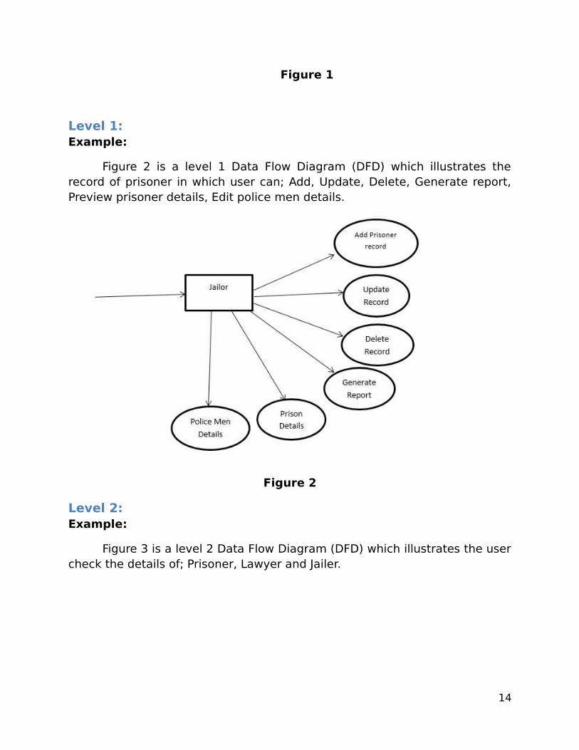
Figure 1
Level 1:Example:
Figure 2 is a level 1 Data Flow Diagram (DFD) which illustrates therecord of prisoner in which user can; Add, Update, Delete, Generate report,Preview prisoner details, Edit police men details.
Figure 2
Level 2:Example:
Figure 3 is a level 2 Data Flow Diagram (DFD) which illustrates the usercheck the details of; Prisoner, Lawyer and Jailer.
14
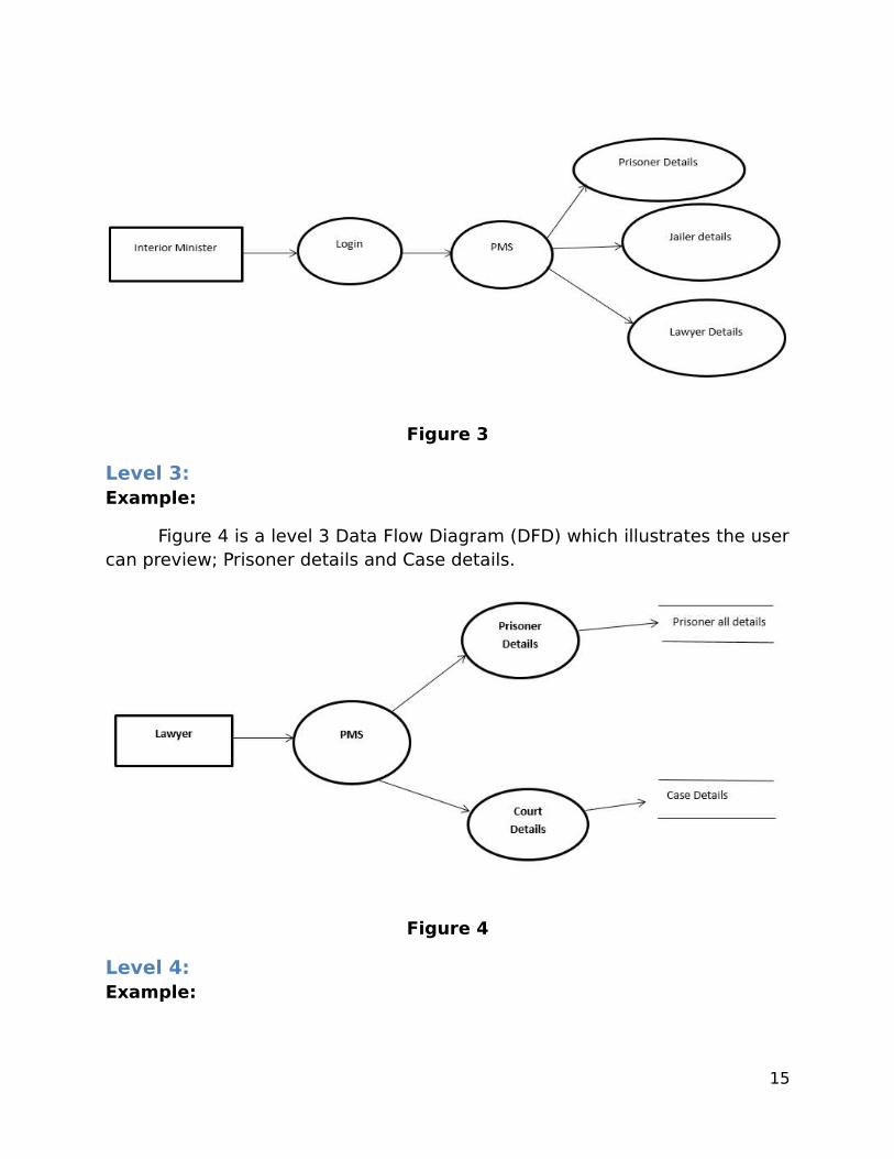
Figure 3
Level 3:Example:
Figure 4 is a level 3 Data Flow Diagram (DFD) which illustrates the usercan preview; Prisoner details and Case details.
Figure 4
Level 4:Example:
15

Figure 5 is a level 4 Data Flow Diagram (DFD) which illustrates thePrisoner request for details which includes his Crime, Punishment and Casedetails.
Figure 5
16

Figure 6
Entity-Relationship Diagram:An Entity-Relationship Diagram, or ERD, is a chart that visually shows
the relationship between database elements. ERDs model an organization'sdata storage necessities with three primary segments: entities, attributes,and relationships.
Example:
Figure 7 is an Entity-Relationship Diagram, or ERD which illustrates therelationship between the entity; Jailer, Prisoner, Lawyer, PMS and InteriorMinister.
17

Figure 7
Figure 8
State Transition Diagram:State transition diagram have been utilized right from the earliest
starting point as a part of object-oriented modeling. The essential thought isto characterize a machine that has various states (thus the term finite statemachine). The machine gets events from the outside world, and every eventcan bring about the machine to move transition with one state then onto thenext.
Example:
Figures 9(a) & (b) are State Transition Diagrams which illustrates thedifferent states of the PMS in between the jailer, interior minister, victim, FIR,and Prisoner.
18

Figure 9(a)
19

Figure 9(b)
Notations:
20

Figure 10
Dialog Map:Demonstrates a user interface (screens, windows, dialog boxes, HTML
pages) and the possible navigation paths among the interfaces components.
Example:
Figure 11 is a Dialog Map which illustrates the external behavior of thePMS. How the user like Jailer, Interior Minister, Prisoner and Lawyer interactwith the PMS.
21

Figure 11
Class Diagram:A class diagram is an outline of the relationships and source code
dependencies among classes in the Unified Modeling Language (UML). In thiscontext, a class characterizes the methods and variables in an object, whichis a particular entity in a program or the unit of code representing to thatentity.
Example:
A figure 12 is a Class Diagram which illustrates the different classesand their objects in the PMS.
22
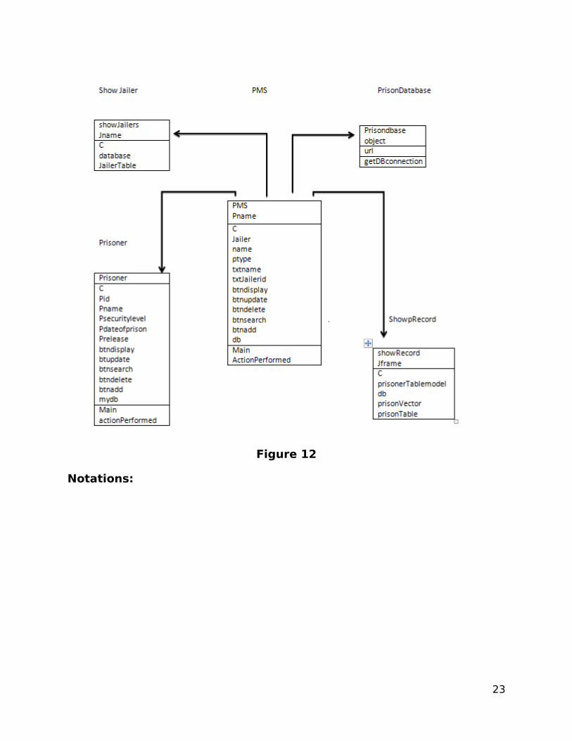
Figure 12
Notations:
23
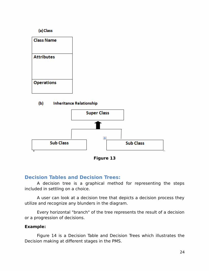
Figure 13
Decision Tables and Decision Trees:A decision tree is a graphical method for representing the steps
included in settling on a choice.
A user can look at a decision tree that depicts a decision process theyutilize and recognize any blunders in the diagram.
Every horizontal "branch" of the tree represents the result of a decisionor a progression of decisions.
Example:
Figure 14 is a Decision Table and Decision Trees which illustrates theDecision making at different stages in the PMS.
24
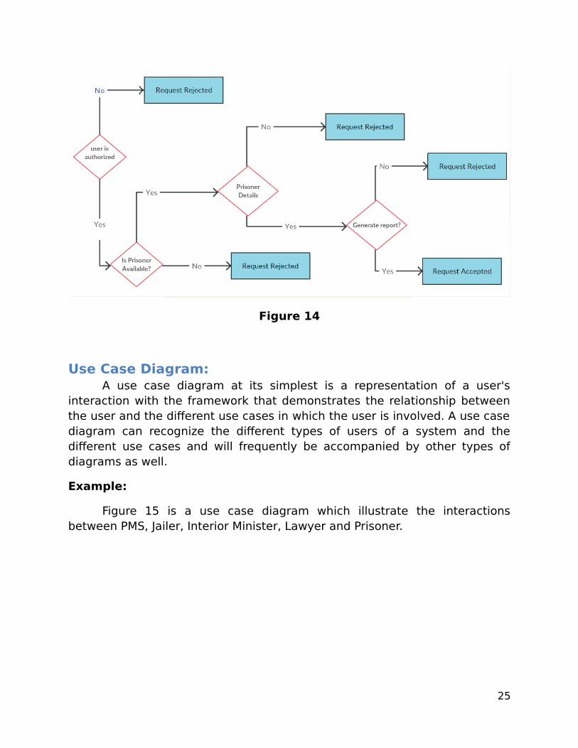
Figure 14
Use Case Diagram:A use case diagram at its simplest is a representation of a user's
interaction with the framework that demonstrates the relationship betweenthe user and the different use cases in which the user is involved. A use casediagram can recognize the different types of users of a system and thedifferent use cases and will frequently be accompanied by other types ofdiagrams as well.
Example:
Figure 15 is a use case diagram which illustrate the interactionsbetween PMS, Jailer, Interior Minister, Lawyer and Prisoner.
25

Figure 15
26

Figure 16
Activity Diagram:Activities diagrams are graphical representations of work processes of
stepwise exercises and actions with backing for decision, emphasis andsimultaneousness. In the Unified Modeling Language, movement outlines areplanned to display both computational and authoritative procedures (i.e.workflows). Activity charts demonstrate the general stream of control.
EXAMPLE:
Figure 17 illustrate that it include the details about login process if anid is valid then login success and search the record if record is found thengenerate the searched report. If not found then enter the new record.
27
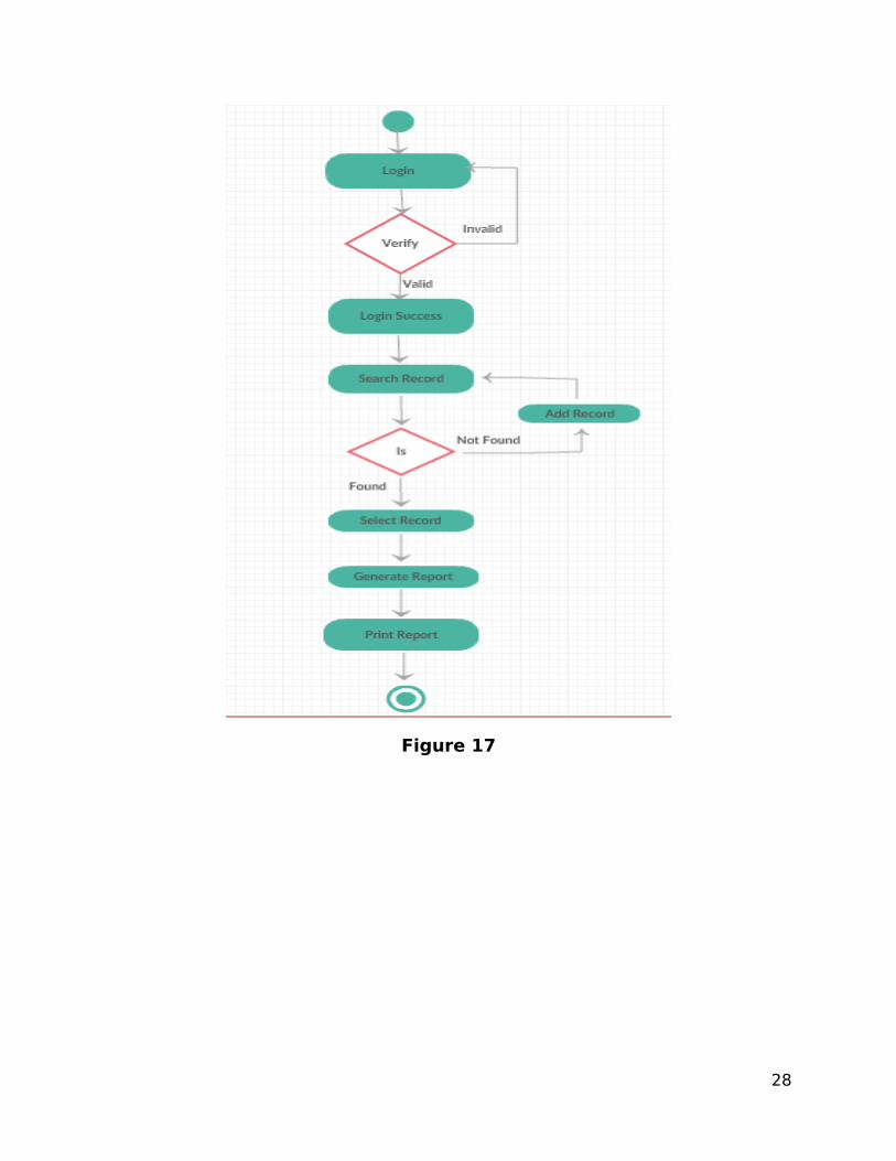
Figure 17
28
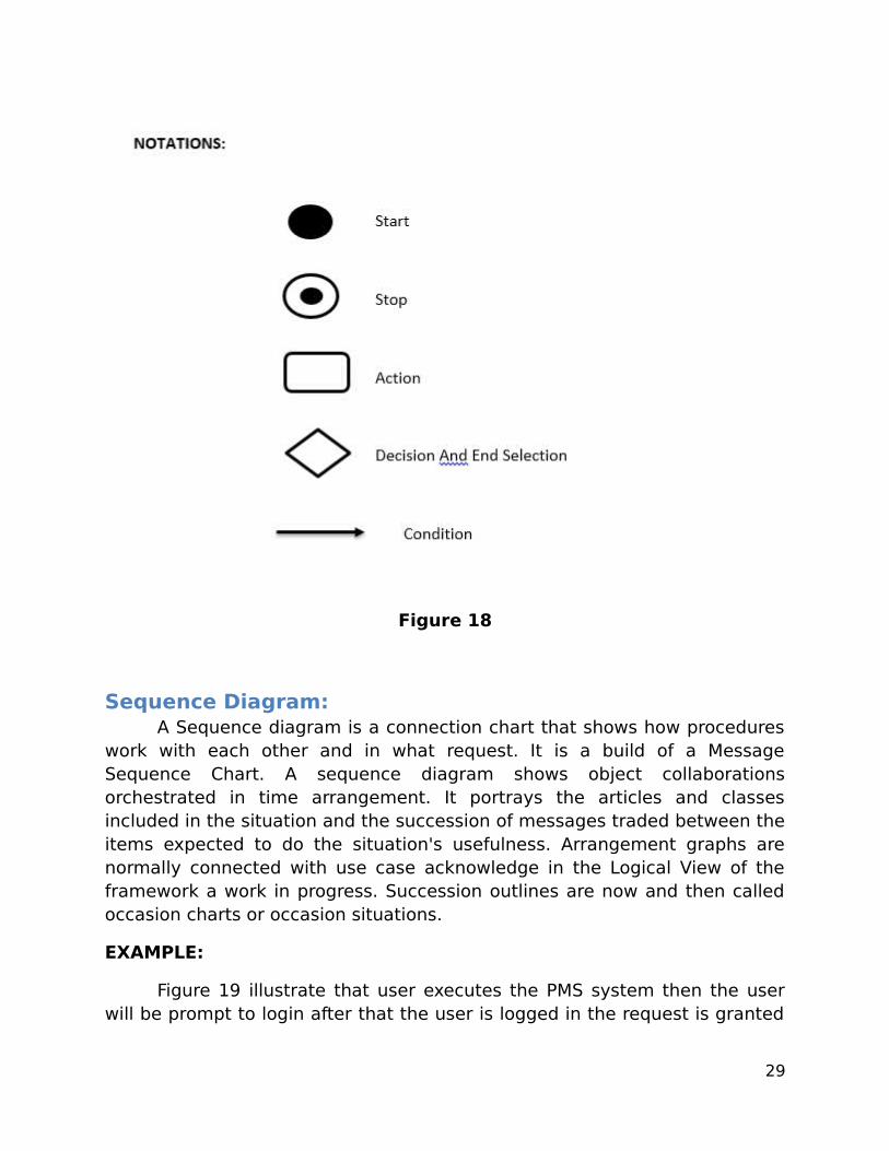
Figure 18
Sequence Diagram:A Sequence diagram is a connection chart that shows how procedures
work with each other and in what request. It is a build of a MessageSequence Chart. A sequence diagram shows object collaborationsorchestrated in time arrangement. It portrays the articles and classesincluded in the situation and the succession of messages traded between theitems expected to do the situation's usefulness. Arrangement graphs arenormally connected with use case acknowledge in the Logical View of theframework a work in progress. Succession outlines are now and then calledoccasion charts or occasion situations.
EXAMPLE:
Figure 19 illustrate that user executes the PMS system then the userwill be prompt to login after that the user is logged in the request is granted
29

to the user then the data sequence is ready the next sequence will start PMSsystem working.
Figure 19
Notations:
Figure 20
30
Software Requirement Specification
1. Introduction:The SRS will give the complete detail of P.M.S and it will help the stakeholder to understand the product.
1.1 Purpose:This is the prison management system and the purpose of this system is to record the details of the data in computerized form not like a previous way i.e. Manual form.
1.2 Document Conventions:The font size of the text will be 12 and the heading size will be 18and theme of the font will be (Calibri) and the color should be black.
1.3 Intended Audience and Reading Suggestions: Following are the list of the readers to whom the SRS list will be directed:
1) Project Manager
2) Interior Minister
3) Jailor
4) Developer
1.4 Project Scope: It will keep the record of the prisoners i.e. the jailor, the policemen and the other employees working in the prison “Scope “ inthe prison management system is that for the jailors it will recordall the details of the prisoners ,lawyers can access the reports ofthe prisoners to do further case. For the interior minister theycan get all the details from this prison management system onone click if these are other request from jailer out-of-scope thenthese request will be checked if these request or valuable ,theywill be added otherwise rejected.
31
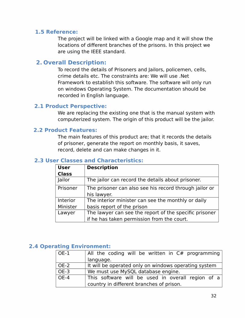
1.5 Reference:The project will be linked with a Google map and it will show the locations of different branches of the prisons. In this project we are using the IEEE standard.
2. Overall Description:To record the details of Prisoners and Jailors, policemen, cells, crime details etc. The constraints are: We will use .Net Framework to establish this software. The software will only run on windows Operating System. The documentation should be recorded in English language.
2.1 Product Perspective:We are replacing the existing one that is the manual system with computerized system. The origin of this product will be the jailor.
2.2 Product Features:The main features of this product are; that it records the details of prisoner, generate the report on monthly basis, it saves, record, delete and can make changes in it.
2.3 User Classes and Characteristics:User Class
Description
Jailor The jailor can record the details about prisoner.
Prisoner The prisoner can also see his record through jailor or his lawyer.
Interior Minister
The interior minister can see the monthly or daily basis report of the prison
Lawyer The lawyer can see the report of the specific prisonerif he has taken permission from the court.
2.4 Operating Environment:OE-1 All the coding will be written in C# programming
language.OE-2 It will be operated only on windows operating systemOE-3 We must use MySQL database engine.OE-4 This software will be used in overall region of a
country in different branches of prison.
32

2.5 Design and Implementation Constraints:CO-1 We will use .Net Frame Work and C# programing
languageCO-2 In this product MySQL will be used as a database.CO-3 We will use a developer coding style. So that each
developer can do his own standard style.CO-4 It has no backward compatibility with earlier product
because it’s the first computerized system.CO-5 It will be compatible on both the 32bit and 64bit
operating system.
2.6 User Documentation:UD-1 We will deliver a user manual along with this
software that will help user to understand thesystem.
2.7 Assumptions and Dependencies:
AS-1 With the prison management system the jailor mayexpect that he want software along with a website.
AS-2 The jailor may want the medical report of theprisoner for the purpose of remand.
AS-3 As this system is for Government Organization, sothe Customer may want also NADRA systemincluded.
3 System Features:
3. x System Feature X: The features will be named as below:
33

“Record” feature will be named as 3.1 and its subsections like updating therecord will be named as “3.x.1”
3. X.1 Description and Priority:
The feature like “record” is used to record a new data and update a changesin it.It will be indicate as high priority in a product.
3. x.2 Stimulus/Response Sequence:Stimulus The Jailer enter the record of prisoner and press the
ADD buttonResponse
The system in response shows the dialog box that therecord has been saved.
Stimulus The Jailer wants to update the prisoner record. So hepresses the UPDATE button.
Response
The system in response will show the dialog box thatthe record has been updated.
Stimulus The Interior Minister wants to know the prisonerreport. So he presses the REPORT button.
Response
The system in response will generate the report of thatspecific prisoner
3. X.3 Functional Requirements:FR-1 If the user input is incorrect then the system in
response will show the dialogue box that the inputu enters is invalid.
FR-2 if the user(jailer) will enter the age of a prisonerless than 18 then the system will show a dialoguebox showing that the prisoner age must be 18 orabove.
FR-3 If the password of the user is incorrect then thesystem will not open.
4 External Interface Requirements: Here the hardware interface will be the computer system whichwill communicate properly with the prison management system. Oursoftware the (P.M.S) will be connected with a database i.e. MySQL.
34

4.1 User Interfaces:UI-1 The size of font will be default that is 12 and the
font style will be Arial the color will be black andthe buttons will be of circle and rectangular shape.
UI-2 The screen resolution will be 720pUI-3 On ctrl+s the file will be saved and on ctrl+o it will
be open and on ctrl+q it will exit the file etc.
4.2 Hardware Interfaces: There is no direct interface between P.M.S and computer system.
4.3 Software Interfaces:SI-1 Our software will run on windows operating system.
SI-2 It will connect with MySQL database.
SI-3 The jailor can add and update the record ofprisoners.
SI-4 The interior minister can generate the monthly andweekly report of the prisoners.
4.4 Communication Interfaces:CI-1 The system will email to the interior minister
about the monthly report of the prison.
CI-2 The system will also send email to the jailor aboutthe specific case of the prisoner.
5 Other Nonfunctional Requirements: The software will be secure, reliable and reusable.
35

5.1 Performance Requirements:PE-1 “90% of data will be retrieve (database query) in 5
seconds on a single user 2.1-GHZ Intel Core i 3running Windows 8 with at least 70 percent of thesystem resources free.”
PE-2 The confirmation message should be displayed inless than 5 sec after Jailer Stimulus.
5.2 Safety Requirements:
SF-1 The product will not open when a firewall is notopen.
SF-2 The data will automatically save after every 5minsin a case any lose because of power off or systemcrash etc.
5.3 Security Required:SR-1 It will take a username and password from every
User to enter into the software system.
SR-2 If the username or password will be incorrect thenit will not enter into the system
5.4 Software Quality Attributes:Efficiency Our software will be efficient over portability.
Security Our software will be secured over reusability.
36
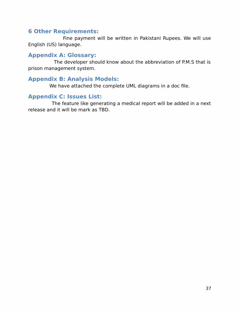
6 Other Requirements: Fine payment will be written in Pakistani Rupees. We will useEnglish (US) language.
Appendix A: Glossary: The developer should know about the abbreviation of P.M.S that isprison management system.
Appendix B: Analysis Models: We have attached the complete UML diagrams in a doc file.
Appendix C: Issues List: The feature like generating a medical report will be added in a nextrelease and it will be mark as TBD.
37