Prisma IP Optical Transport Release Notes, Release 7.8 · PDF filePrisma IP Optical Transport...
38
Prisma IP Optical Transport Release Notes, Release 7.8.1 Overview Introduction This software release supports software on the Prisma IP ™ M-Series, C-Series, E100, E200, E500, E500A, and ES520 platforms. This release note describes features in Release 7.8.1 as well as resolved and outstanding issues. Release 7.8.1 consists of the following: • R7.8.1 64-bit Element Management System (EMS) for 64-bit Windows • R7.8.0 Element Management System (EMS) • R7.8.0 Element Management System Command Line Interface (EMS-CLI) • R7.7.1 SYSCON and E-Series images • R7.7.0 M/C-Series Line and Switch Card images Release 7.8.1 updates EMS, introduces a 64-bit version of the EMS that runs on 64-bit Windows platforms, and introduces a new EMS-CLI application. These applications work with the embedded images from Release 7.7. Safe Operation for Software Controlling Optical Transmission Equipment If this document discusses software, the software described is used to monitor and/or control ours and other vendors’ electrical and optical equipment designed to transmit video, voice, or data signals. Certain safety precautions should be observed when operating equipment of this nature. For equipment specific safety requirements, refer to the appropriate section of the equipment documentation. For safe operation of this software, refer to the following warnings. WARNINGS: • Ensure that all optical connections are complete or terminated before using this equipment to remotely control a laser device. An optical or laser device can pose a hazard to remotely located personnel when operated without their knowledge.
-
Upload
truongdang -
Category
Documents
-
view
226 -
download
1
Transcript of Prisma IP Optical Transport Release Notes, Release 7.8 · PDF filePrisma IP Optical Transport...

Prisma IP Optical Transport Release Notes, Release 7.8.1 Overview
Introduction This software release supports software on the Prisma IP™ M-Series, C-Series, E100, E200, E500, E500A, and ES520 platforms. This release note describes features in Release 7.8.1 as well as resolved and outstanding issues.
Release 7.8.1 consists of the following:
• R7.8.1 64-bit Element Management System (EMS) for 64-bit Windows
• R7.8.0 Element Management System (EMS)
• R7.8.0 Element Management System Command Line Interface (EMS-CLI)
• R7.7.1 SYSCON and E-Series images
• R7.7.0 M/C-Series Line and Switch Card images
Release 7.8.1 updates EMS, introduces a 64-bit version of the EMS that runs on 64-bit Windows platforms, and introduces a new EMS-CLI application. These applications work with the embedded images from Release 7.7.
Safe Operation for Software Controlling Optical Transmission Equipment If this document discusses software, the software described is used to monitor and/or control ours and other vendors’ electrical and optical equipment designed to transmit video, voice, or data signals. Certain safety precautions should be observed when operating equipment of this nature.
For equipment specific safety requirements, refer to the appropriate section of the equipment documentation.
For safe operation of this software, refer to the following warnings.
WARNINGS: • Ensure that all optical connections are complete or terminated before using
this equipment to remotely control a laser device. An optical or laser device can pose a hazard to remotely located personnel when operated without their knowledge.

4026643 Rev B Prisma IP Optical Transport Release Notes, Release 7.8.1 2
• Allow only personnel trained in laser safety to operate this software. Otherwise, injuries to personnel may occur.
• Restrict access of this software to authorized personnel only. • Install this software in equipment that is located in a restricted access area.

4026643 Rev B Prisma IP Optical Transport Release Notes, Release 7.8.1 3
In This Document This document contains the following topics.
Topic See Page
Related Product Documentation 4
New Features in Release 7.8.1 6
Compatibility 11
Configuration 17
Upgrade and Downgrade Instructions 20
Resolved and Outstanding Issues 30
For Information 36

4026643 Rev B Prisma IP Optical Transport Release Notes, Release 7.8.1 4
Related Product Documentation
The following documentation describes the NOS operating system, which is the software that runs on Prisma IP platforms; the EMS management software that runs on Solaris 8 or later, Windows XP, Windows 2000 Professional, and server machines; and the EMS-CLI that runs on Windows machines.
Refer to the following publications for additional hardware and software information.
Title Part Number Description
Prisma IP Optical Transport M-Series Installation and Configuration User’s Guide
4020556 Describes how to install and configure the Prisma IP M-Series platform.
Prisma IP Optical Transport C-Series Installation and Configuration User’s Guide
4020554 Describes how to install and configure the Prisma IP C-Series platform.
Prisma IP Optical Transport E500 Installation and Configuration User’s Guide
4020547 Describes how to install and configure the Prisma IP E500 platform.
Prisma IP Optical Transport E200 Installation and Configuration User’s Guide
4020548 Describes how to install and configure the Prisma IP E200 platform.
Prisma IP Optical Transport ES520 Installation and Configuration User’s Guide
4020549 Describes how to install and configure the Prisma IP ES520 platform.
Prisma IP Optical Transport E100 Installation and Configuration User’s Guide
4020550 Describes how to install and configure the Prisma IP E100 platform.
Prisma IP Optical Transport Maintenance and Troubleshooting User’s Guide
4020552 Contains task-oriented steps used to perform routine maintenance and troubleshooting procedures on Prisma IP switches. Information related to maintaining hardware and software units is also included. Special focus is given on alarms and how to respond to them in addition to emergency recovery and restoration procedures.
Prisma IP Optical Transport Element Management System (EMS) User’s Guide
4025313 Describes how to perform routine operation, administration, and maintenance procedures on Prisma IP switches using the EMS.

4026643 Rev B Prisma IP Optical Transport Release Notes, Release 7.8.1 5
Title Part Number Description
Provisioning is documented in the Prisma IP Optical Transport Service Management Framework User’s Guide.
Prisma IP Optical Transport Command Line Interface (CLI) Reference Guide
4020555 Describes the CLI commands for the Prisma IP system.
Prisma IP Optical Transport Service Management Framework User’s Guide
4020553 Describes the different services available for configuration with the Prisma IP platforms using the Element Management System (EMS) Service Management Framework (SMF).
Prisma IP Optical Transport Glossary
4020546 Defines key terminology used in the Prisma IP documentation suite.
Prisma IP Optical Transport Element Management System Command Line Interface (EMS-CLI) User’s Guide
4025318 Describes EMS-CLI commands and how to perform procedures available from the EMS-CLI such as moving services.

4026643 Rev B Prisma IP Optical Transport Release Notes, Release 7.8.1 6
New Features in Release 7.8.1
New EMS-CLI Application This release introduces the new EMS-CLI application, “emscli.exe.”
As shown below, the EMS-CLI provides a second way to interact with the EMS Server. The existing EMS Client provides an intuitive point-and-click graphical user interface. The new EMS-CLI provides a text-based command line interface that allows scripting and automation of user operations. However, the EMS-CLI only supports a subset of the features available from the EMS Client.
Note: The EMS-CLI and EMS server should run on the same host machine. Otherwise, the EMS-CLI will not receive the response status from the EMS server. Service Move Specifically, the EMS-CLI supports a Service Move feature. The EMS-CLI provides an interface to run scripts for bulk deletion and creation of services, automating the movement of services.
For example, to relieve a bandwidth bottleneck, the user may wish to move tens or hundreds of services being aggregated at a Subtending Ring Card (SRC) from one node on a ring to a different node on that ring. The EMS-CLI provides a way to automate this process. This will be less time consuming and less error-prone than manual EMS Client point-and-click operations, allowing more work to be performed in a tight maintenance window.
This Service Move feature is applicable for the following scenarios:
• One endpoint of a service needs to be moved to a different node
• A service needs to be re-provisioned on a different path because the network topology changed.
The EMS-CLI can move the following types of services:
• Ethernet Private Line (EPL)
• TDM Private Line (TPL)

4026643 Rev B Prisma IP Optical Transport Release Notes, Release 7.8.1 7
EMS Enhancements This release introduces the following enhancements to EMS.
Server Interoperation with EMS-CLI This release enables the EMS Server to work with the new EMS-CLI application.
Detailed Topology View (DTV) Profile Export The EMS DTV feature allows the user to view all the nodes in his network in a single window. By default, the nodes will be arranged in a circle. With a large network, this layout will be cluttered and unusable. Each user is able to rearrange the nodes into a more useful layout, save this layout in his user’s profile and recover this layout next time he uses the DTV feature. With a large network, each user may spend a significant amount of time rearranging nodes.
This release allows the user to load a layout saved by any other user in addition to his saved layout.
Support for 64-bit Windows This release includes a 64-bit version of the EMS, “ems_64.exe,” for 64-bit Windows hosts. The recommended host configuration is as follows: • Dual Quad Core Xeon processors • Windows Server 2003 64-bit Operating System • 8 GB RAM
The 64-bit EMS will perform faster than the 32-bit EMS, “lms.exe,” on the above host configuration for operations such as Transparent LAN Service (TLS) creation.
Unlike the 32-bit EMS, the 64-bit EMS does not include the MIB browser “lmsmib.”
EMS Minimum Platform Requirements The minimum platform requirements for Release 7.8 of EMS are as follows.
Solaris Requirements Solaris EMS Server: Solaris based server machine running Solaris 8 or later.
Solaris EMS Client: Solaris based workstation running Solaris 8 or later.
Requirement EMS Server EMS Client
Hardware Sun UltraSPARCIIIi 1.5 GHz or better processor or AMD Opteron 2.2 GHz or better processor CD-ROM drive 4 MB video RAM Color monitor (recommended)
Sun UltraSPARCIIi 650 MHz or better processor 21” color monitor (recommended) CD-ROM drive 4 MB video card with 1027 x 768 resolution (minimum)
Operating environment
Solaris 8 or later Solaris 8 or later

4026643 Rev B Prisma IP Optical Transport Release Notes, Release 7.8.1 8
Requirement EMS Server EMS Client
RAM 1 to 100 nodes: 512 MB free RAM (minimum) 1 GB free RAM (recommended) 101 to 250 nodes: 1 GB free RAM (minimum) 2 GB free RAM (recommended) > 250 nodes: 2 GB free RAM (minimum)
1 to 250 nodes: 256 MB free RAM (minimum) 512 MB free RAM (recommended) > 250 nodes: 1 GB free RAM (minimum)
Disk space 1 to 250 nodes: 50 GB free disk space (minimum) 100 GB free disk space (recommended) > 250 nodes: 100 GB free disk space (minimum)
1 to 250 nodes: 5 GB free disk space (minimum) > 250 nodes: 10 GB free disk space (minimum)
Java Runtime Environment (JR–) - bundled with EMS
1.5.0 1.5.0
The above requirements are the recommended minimum when running the EMS Server standalone, with the EMS Client installed on another workstation. These requirements support small to medium-sized networks. Larger networks will require faster servers. If you need to run the client on the same workstation, more CPU and RAM will be used, so a faster processor or a dual processor may be required, as well as additional disk space.
Windows Requirements Scalability benchmark testing indicated that the size of the network (the number of managed nodes) does not drastically increase the CPU load on the EMS Server. However, RAM requirements increase with the size of the network.
Note: Windows 95, NT, 98, 98SE, and ME are not qualified and are not supported for the EMS Client and Server.

4026643 Rev B Prisma IP Optical Transport Release Notes, Release 7.8.1 9
The version of both client and server must be the same. Specific Windows requirements are shown in the following table.
Requirement EMS Server EMS Client
Hardware CD-ROM drive 4 MB video RAM Color monitor (recommended) 1 to 500 nodes: Intel Pentium III or better PC 3.2 GHz or better processor or AMD Athlon 64 3200+ or better processor >500 nodes: Dual Quad Core Xeon 2.66GHz or better processor
21” color monitor (recommended) CD-ROM drive 1.44 MB 3.5” diskette drive 4 MB video card with 1027 x 768 resolution (minimum) 1 to 100 nodes: Intel Pentium III or better PC, 800 MHz or better processor > 100 nodes: 2GHz or better processor
Operating environment Windows 2000 Workstation Windows 2000 Advanced Server Windows XP Professional Windows 2003 Server
Windows 2000 Workstation Windows 2000 Advanced Server Windows XP Professional Windows 2003 Server
RAM 1 to 100 nodes: 512 MB free RAM (minimum) 1 GB free RAM (recommended) 101 to 250 nodes: 1 GB free RAM (minimum) 2 GB free RAM (recommended) > 250 nodes: 2 GB free RAM (minimum) > 500 nodes: 4 GB free RAM (minimum)
1 to 250 nodes: 512 MB free RAM (minimum) > 250 nodes: 1 GB free RAM (minimum)
Disk space 1 to 250 nodes: 50 GB free disk space (minimum) 100 GB free disk space (recommended) > 250 nodes: 100 GB free disk space (minimum)
1 to 250 nodes: 5 GB free disk space (minimum) > 250 nodes: 10 GB free disk space (minimum)
Java Runtime Environment (JR–) - bundled with EMS
1.5.0 1.5.0

4026643 Rev B Prisma IP Optical Transport Release Notes, Release 7.8.1 10
The preceding requirements are the recommended minimum when running the EMS Server standalone, with the EMS Client installed on another workstation. These requirements support small to medium-sized networks. Larger networks will require faster servers. If you need to run the client on the same workstation, more CPU and RAM will be used, so a faster processor or a dual processor may be required, as well as additional disk space.
EMS-CLI Minimum Platform Requirements The EMS-CLI only runs on Windows platforms. The minimum platform requirements for Release 7.8 of EMS-CLI are the same as the EMS Client minimum Windows platform requirements.

4026643 Rev B Prisma IP Optical Transport Release Notes, Release 7.8.1 11
Compatibility
Backwards Compatibility Release 7.8.1 consists of the following:
• R7.8.1 64-bit Element Management System (EMS) for 64-bit Windows
• R7.8.0 Element Management System (EMS)
• R7.8.0 Element Management System Command Line Interface (EMS-CLI)
• R7.7.1 SYSCON and E-Series images
• R7.7.0 M/C-Series Line and Switch Card images
Release 7.8.1 supports new installations as well as upgrades from Release 5.0.x, 6.x, and 7.x. Release 7.8.1 works with the Release 7.7 embedded images. Within one node, the SYSCONs must run R7.7.1 and all other cards must run R7.7.0 to fully utilize all the capabilities of the release. Upgrades must be done for all nodes on the ring for full Release 7.8.1 or 7.7.1 functionality. Services that are supported in Release 7.7.1 and that existed in Release 6.x and 5.0.x will continue to work after upgrading to Release 7.8.1 or 7.7.1. We do not recommend creating new services on Release 7.8.1 or 7.7.1 until the entire ring has been upgraded to Release 7.7.1.
The 7.7.0 ASI image is not compatible with earlier ASI images on a ring. Both ASI Card end points of a video service must be at 7.7.0 for the service to work.
For proper operation, the EMS server must be running Software Release 7.7.0, 7.8.0, 7.8.1, or higher to manage a node with Software Release 7.7.1 runtime images. In order to support new hardware and services on the ring introduced in Release 7.7.1, the EMS station must be running Release 7.7.0, 7.8.0, 7.8.1, or higher. For more information on the upgrade/downgrade procedures, refer to Upgrade and Downgrade Instructions later in this document.
The EMS server must be running Software Release 7.8.0, 7.8.1 or higher to work with the Release 7.8.0 EMS-CLI.
Hardware Compatibility All the previous hardware from earlier releases, as listed in the following table, is supported in this release.
Hardware
Platforms
SYSTEM, Chassis, C-Series
SYSTEM, Chassis, M-Series
SYSTEM, Chassis, E200, E1
SYSTEM, Chassis, E200, T1

4026643 Rev B Prisma IP Optical Transport Release Notes, Release 7.8.1 12
Hardware
SYSTEM, E510
SYSTEM, E510A
SYSTEM, E520
SYSTEM, E520A
SYSTEM, ES520
SYSTEM, E110
SYSTEM, E150
Front Cards
COMEQUIP, Syscon R card
COMEQUIP, Syscon 2 card
COMEQUIP, Syscon 2, V2 card
COMEQUIP, 10G Switch Card
COMEQUIP, 20G Switch Card
COMEQUIP, 20G2 Switch Card
COMEQUIP, 20G2-HS Switch Card
LINE CARD, Subtend Ring (SRC), 1G
LINE CARD, Subtend Ring (SRC), 1-2.5 G
LINE CARD, Subtend Ring (SRC), 1-2.5 G-HS
LINE CARD, 8xT1/E1
LINE CARD, 8x10/100BT
LINE CARD, 2xGigE
LINE CARD, 2xGigE R
LINE CARD, 2xGigE ES
LINE CARD, 12xDS3
LINE CARD, 4xVideo Data Processor IF

4026643 Rev B Prisma IP Optical Transport Release Notes, Release 7.8.1 13
Hardware
LINE CARD, 8xVideo Data Processor, ASI
LINE CARD, TDM-U
COMEQUIP, Utility card
Back Cards
COMEQUIP, Alarm card
I/O card, 1G RPT, 1310 nm
I/O card, 1G RPT, 1550 nm
I/O card, 1-2.5 G RPT, 1310 nm
I/O Card, 1-2.5 G RPT, w/DWDM Bypass, 1510 nm
I/O Card, 1-2.5 G RPT, 1550 nm
I/O CARD, Subtend Ring (SRC), 1G
I/O CARD, Subtend Ring (SRC), 1-2.5G
I/O CARD, 8xT1/E1
I/O CARD, 8x10/100BT
I/O CARD, 8x10/100FX
I/O CARD, 2xGigE
I/O CARD, INPUT, 8xASI
I/O CARD, OUTPUT, 8xASI
I/O CARD, INPUT, 4xIF
I/O CARD, OUTPUT, 4xIF
I/O CARD, 12xDS3/E3
I/O CARD, 4xOC3/STM1
I/O CARD, 1-2.5 G RPT, CWDM, 1550 nm
I/O CARD, 1-2.5 G RPT, ITU21, 170 km
I/O CARD, 1-2.5 G RPT, ITU23, 170 km
4026643 Rev B Prisma IP Optical Transport Release Notes, Release 7.8.1 14
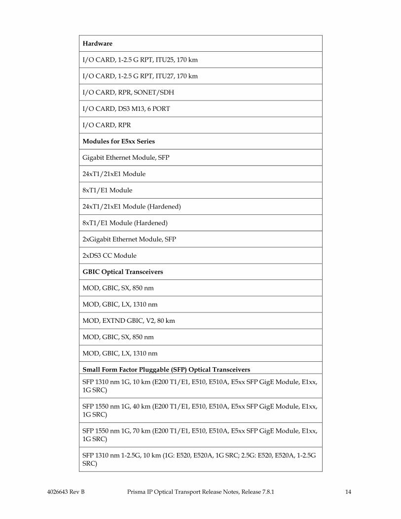
Hardware
I/O CARD, 1-2.5 G RPT, ITU25, 170 km
I/O CARD, 1-2.5 G RPT, ITU27, 170 km
I/O CARD, RPR, SONET/SDH
I/O CARD, DS3 M13, 6 PORT
I/O CARD, RPR
Modules for E5xx Series
Gigabit Ethernet Module, SFP
24xT1/21xE1 Module
8xT1/E1 Module
24xT1/21xE1 Module (Hardened)
8xT1/E1 Module (Hardened)
2xGigabit Ethernet Module, SFP
2xDS3 CC Module
GBIC Optical Transceivers
MOD, GBIC, SX, 850 nm
MOD, GBIC, LX, 1310 nm
MOD, EXTND GBIC, V2, 80 km
MOD, GBIC, SX, 850 nm
MOD, GBIC, LX, 1310 nm
Small Form Factor Pluggable (SFP) Optical Transceivers
SFP 1310 nm 1G, 10 km (E200 T1/E1, E510, E510A, E5xx SFP GigE Module, E1xx, 1G SRC)
SFP 1550 nm 1G, 40 km (E200 T1/E1, E510, E510A, E5xx SFP GigE Module, E1xx, 1G SRC)
SFP 1550 nm 1G, 70 km (E200 T1/E1, E510, E510A, E5xx SFP GigE Module, E1xx, 1G SRC)
SFP 1310 nm 1-2.5G, 10 km (1G: E520, E520A, 1G SRC; 2.5G: E520, E520A, 1-2.5G SRC)

4026643 Rev B Prisma IP Optical Transport Release Notes, Release 7.8.1 15
Hardware
SFP 1310 nm 1-2.5G, 10 km, Industrial (1G: E200 T1/E1, E510, E510A, E520, E520A, E5xx SFP GigE Module, E1xx, 1G SRC, RPR; 2.5G: E520, E520A, 1-2.5G SRC, RPR)
SFP CWDM 1-2.5G, 70 km/2.5G, 100 km/1G (1G: E200 T1/E1, E510, E510A, E1xx RPR, E520, E520A, 1G SRC, RPR; 2.5G: E520, E520A, 1-2.5G SRC, RPR)
1470 nm
1490 nm
1510 nm
1530 nm
1550 nm
1570 nm
1590 nm
1610 nm
SFP 850 nm 1G (1G: E5xx SFP GigE Module, E1xx SFP GigE, 1G SRC)
SFP 850 nm 1G (1G: E5xx SFP GigE Module, E1xx SFP GigE, 1G SRC)
SFP 1310 nm 155 Mbps, IR (TDM-U)
SFP 1310 nm 155 Mbps, SR (TDM-U)
SFP Cable 1-2.5G, Passive (1G: 1G SRC; 2.5G: 1-2.5G SRC)
SFP 1550 nm 1G 80 km (E200 T1/E1, 1G SRC, E510, E510A, E5xx SFP GigE Module, E1xx)
SFP 1310 nm 1G 40 km (E200 T1/E1, 1G SRC, E510, E510A, E5xx SFP GigE Module, E1xx)
SFP 1310 nm, OC48 SR, OC12/3 compatible, Industrial (SONET/SDH RPR, ES520)
SFP 1310 nm, OC12 IR-1 OC3 compatible (SONET/SDH RPR, ES520)
SFP 1310 nm, 2.5G/20 km, 1G/30 km, OC48 IR-1, OC12/3 compatible (1G: E520, E520A; 2.5G: E520, E520A, 1-2.5G SRC, RPR; OC48/12/3: SONET/SDH RPR, ES520)
SFP 1550 nm, 2.5G/70 km, 1G/100 km, OC48 LR-2, OC12/3 compatible (1G: E200 T1/E1, E510, E510A, E1xx RPR, E520, E520A, 1G SRC, RPR; 2.5G: E520, E520A, 1-2.5G SRC, RPR; OC48/12/3: SONET/SDH RPR, ES520)
SFP CWDM 1-2.5G, 40 km/2.5G, 60 km/1G (1G: 1470 nm

4026643 Rev B Prisma IP Optical Transport Release Notes, Release 7.8.1 16
Hardware
E200 T1/E1, E510, E510A, E1xx RPR, E520, E520A, 1G SRC, RPR; 2.5G: E520, E520A, RPR) 1490 nm
1510 nm
1530 nm
1550 nm
1570 nm
1590 nm
1610 nm
SFP OC48, 1310 nm, LR-1 1G 50km, 2.5G 35 km (1G: E520, E520A; 2.5G: E520, E520A, 1-2.5G SRC, RPR; OC48/12/3: SONET/SDH RPR, ES520)
SFP 1000BT, 100m (E5xx SFP GigE Module)
SFP 1310 nm 1G 40 km, Industrial (E200 T1/E1, 1G SRC, E510, E510A, E5xx SFP GigE Module, E1xx, RPR)
SFP 1550nm 1G 80 km, Industrial (E200 T1/E1, 1G SRC, E510, E510A, E5xx SFP GigE Module, E1xx, RPR)
SFP 1310 nm OC48 LR-1, Industrial (1G: E520, E520A; 2.5G: E520, E520A)
SFP 1550 nm OC48 LR-2, Industrial (1G: E520, E520A; 2.5G: E520, E520A)
SFP CWDM 1G, 120 km (E200 T1/E1, E510, E510A, E1xx RPR, 1G SRC, RPR)
1470 nm
1490 nm
1510 nm
1530 nm
1550 nm
1570 nm
1590 nm
1610 nm
DWDM SFP, 0 dBm, APD, 80 km Dispersion, Channels 17-62 (E510, E510A, E520A, ES520 RPR)
The M/C-Series SYSCON 2, V2 Cards are not compatible with releases prior to 7.7.1.

4026643 Rev B Prisma IP Optical Transport Release Notes, Release 7.8.1 17
Configuration
Valid Operational Configuration All nodes on the same RPR ring must be running the same release, except during an upgrade.
Prisma IP Configuration The following table shows the Prisma IP M-Series and C-Series slot configuration.
M-Series Location/Slot
C-Series Location/Slot Comment
Front Card
Line 1-6 & 13-18 1-4
Switch (7,8), (9,10) (5,6), (7,8) Double width cards - 2 slots each Redundant Switch card
Syscon (all types)
11,12 9 Redundant Syscon for M-Series One RS-232 on each Syscon
Utility 19 N/A For the C-Series, the power monitoring capability is provided by the fan tray.
Rear Card
Line I/O 1-6 & 13-18 1-4
Ring I/O West: (7,8) East: (9,10)
West: (5,6) East: (7,8)
Double width cards - 2 slots each
Alarm 11 9 NMS Port and Connectors for Alarm Relay (Optional for C-Series)
Fan Tray Top Side
Total Number of Slots 19 9
4026643 Rev B Prisma IP Optical Transport Release Notes, Release 7.8.1 18
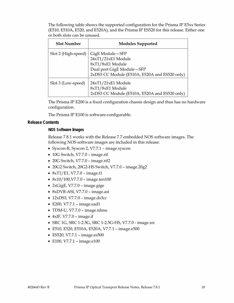
The following table shows the supported configuration for the Prisma IP E5xx Series (E510, E510A, E520, and E520A), and the Prisma IP ES520 for this release. Either one or both slots can be unused.
Slot Number Modules Supported
Slot 2 (High-speed) GigE Module—SFP 24xT1/21xE1 Module 8xT1/8xE1 Module Dual port GigE Module—SFP 2xDS3 CC Module (E510A, E520A and ES520 only)
Slot 3 (Low-speed) 24xT1/21xE1 Module 8xT1/8xE1 Module 2xDS3 CC Module (E510A, E520A and ES520 only)
The Prisma IP E200 is a fixed configuration chassis design and thus has no hardware configuration.
The Prisma IP E100 is software-configurable.
Release Contents NOS Software Images Release 7.8.1 works with the Release 7.7 embedded NOS software images. The following NOS software images are included in this release: • Syscon-R, Syscon 2, V7.7.1 – image.syscon • 10G Switch, V7.7.0 – image.rif • 20G Switch, V7.7.0 – image.rif2 • 20G2 Switch, 20G2-HS Switch, V7.7.0 – image.20g2 • 8xT1/E1, V7.7.0 – image.t1 • 8x10/100,V7.7.0 – image.ten100 • 2xGigE, V7.7.0 – image.gige • 8xDVB-ASI, V7.7.0 – image.asi • 12xDS3, V7.7.0 – image.ds3cc • E200, V7.7.1 – image.ead1 • TDM-U, V7.7.0 – image.tdmu • 4xIF, V7.7.0 – image.if • SRC 1G, SRC 1-2.5G, SRC 1-2.5G-HS, V7.7.0 - image.src • E510, E520, E510A, E520A, V7.7.1 – image.e500 • ES520, V7.7.1 – image.es500 • E100, V7.7.1 – image.e100

4026643 Rev B Prisma IP Optical Transport Release Notes, Release 7.8.1 19
EMS files The following EMS files are included in this release: • EMS server/client, V7.8.1 (64-bit Windows) – ems_64.exe • EMS server/client, V7.8.0 (Windows) – lms.exe • EMS server/client, V7.8.1 (Solaris) – lms.bin • EMS non-GUI installation, V7.8.0 (Solaris only), – lms.zip
EMS Server and Client are included in a single package and can be selected during the installation process.
EMS-CLI files The following EMS-CLI files are included in this release: • EMS-CLI, V7.8.0 (Windows) – emscli.exe

4026643 Rev B Prisma IP Optical Transport Release Notes, Release 7.8.1 20
Upgrade and Downgrade Instructions
We recommend that you read the Technical Publications listed earlier in this document in Related Product Documentation, prior to the upgrade or downgrade.
Obtaining Technical Assistance For assistance upgrading or downgrading, contact us. Refer to For Information later in this document for contact information. Customer Support is included with a PSA.
Upgrade Procedure Release 7.8.1 works with the Release 7.7 embedded NOS software images. The following sections provide step-by-step procedures for upgrading EMS to Release 7.8.1, and NOS image files to Release 7.7.1. The procedures are applicable to the Prisma IP C-Series, M-Series, E100, E200, E500, E500A, and ES520 platforms.
With the E100, E200, E500, E500A, and ES520, there is only a single image each. The upgrade and downgrade procedures are basically the same as for the C-Series and M-Series, except that only a single image applies.
Read the entire instructions before proceeding with the software upgrade. Basic configuration information is contained in these instructions. This document assumes administrative knowledge of your Prisma IP hardware. For assistance during the upgrade, contact us. Customer Support is included with a PSA.
Considerations The following is a list of items that should be addressed: • Download Release 7.8.1. Call Cisco Services for assistance. Follow the menu
options to speak with a service engineer. Refer to the section later in this document titled For Information for telephone numbers.
• Schedule a service maintenance window. It is advised that you allocate a minimum time of 15 minutes per node for this procedure. Your RPR ring should not be affected during the download and installation of images, but the ring will be affected during the reset of nodes.
• Review the release notes and installation and configuration guide(s) prior to the service window. Refer to Related Product Documentation for a list of guides. Contact Customer Support for further information on Product Documentation.
• If you are running a release prior to Release 5.0.x, upgrade to Release 5.0.x, before proceeding with the upgrade.
Materials Needed For the software upgrade, you will need the following materials: • Access to the Prisma IP system you plan to upgrade. • A PC running VT100 terminal emulation. • A serial data null modem cable with two DB9F connectors. • Serial port settings configured to 9600 baud, 1 stop bit, 8 bytes, no parity. • A local FTP server and knowledge of its IP address. • A username and password on the FTP server.

4026643 Rev B Prisma IP Optical Transport Release Notes, Release 7.8.1 21
• Image files from us for the version you wish to upload, loaded to a new folder on the FTP server.
• For E510 and E520, an adaptor (DB9-RJ45/RS-232) console port.
Upgrade EMS, PROMs, and Images It is recommended that the following sequence be used during the software upgrade: EMS software should be upgraded first, PROMs second if needed, and then the runtime images.
Use the procedure provided in this document for the EMS and the runtime image software upgrade.
PROM upgrades should only be performed if you are upgrading from software releases below 2.2 or in cases recommended in these release notes. An R4.0 Syscon PROM upgrade is optional for obtaining the Password recovery feature.
CAUTION: Use caution when upgrading PROMs since there is no disaster recovery for PROM upgrades. Failure during a PROM upgrade would require the card to be sent back for replacement. Contact us before attempting any PROM upgrades.
Step Task
1. Upgrade the EMS software to version 7.8.0 using the instructions provided in Chapter 2, “Installation” in the Prisma IP Optical Transport Element Management System (EMS) User’s Guide.
For supported 64-bit Windows hosts, optionally upgrade to version 7.8.1 64-bit EMS using the instructions provided in Chapter 2, “Installation” in the Prisma IP Optical Transport Element Management System (EMS) User’s Guide. However, in this case the installation file is “ems_64.exe” instead of “lms.exe.”
2. From the FTP server, ping the shelf IP addresses of all nodes planned for an upgrade. Ping must be successful in order for the upgrade to proceed.
3. To determine what release you are running, use the EMS Software Download window. Each of the cards will show a software release version.
If upgrading embedded NOS images from a release prior to 5.0.x, upgrade to 5.0.x before proceeding with the upgrade to 7.7.1.
Upgrading to Release 7.7.1 embedded NOS images from a Pre-7.1.0 Release This section details the steps required to upgrade a node to release 7.7.1 from a release prior to 7.1.x.

4026643 Rev B Prisma IP Optical Transport Release Notes, Release 7.8.1 22
Many of the following steps can only be performed using the CLI. Where applicable, the steps using EMS and/or the CLI are documented. EMS will be given preference whenever possible.
Using the Console Command to Connect to Other Nodes in a Ring This section describes how to use the console command from the seed or gateway node of the ring to connect to other nodes in the ring. Note that this section covers both the main ring and subtending rings; the concepts are the same.
Step Task
1. Verify the set of nodes that are in the rings using the show topology command. Example:
> show topology Topology Table Topology for ring-3/1 Topology State: Complete Ring Protection State: Up Number Nodes: 4 Last Change: 0d 04:59:00 Node Type East State West State * 10.0.15.114 etn 10.0.15.7 Up 10.0.15.138 Up 10.0.15.7 ltn 10.0.15.151 Up 10.0.15.114 Up 10.0.15.151 ltn 10.0.15.138 Up 10.0.15.7 Up 10.0.15.138 ltn 10.0.15.114 Up 10.0.15.151 Up Topology for ring-7/1 Topology State: Complete Number Nodes: 2 Last Change: 0d 04:58:15 Node Type East State West State * 10.0.14.114 ltn 10.0.14.102 Up 10.0.14.102 Up 10.0.14.102 itn 10.0.14.114 Up 10.0.14.114 Up
2. Using the console command, connect to each of the other nodes in the ring.
Example:
> console 10.0.15.138 Trying 10.0.15.138 ... Connected to 10.1.15.138. To terminate session use ^_-q. telnetd: attaching session to /pty/1 telnetd: request from 10.0.15.114:3602 attached to /pty/1 login: apollo password: ############ Local user apollo logged in at MON JUN 23 20:01:41 2003 UTC Last logged in SUN JUN 22 01:14:56 2003 UTC User rights are 7ff/7ff Note: If there is more than one subtending ring, then you will need to use nested console commands. For example, if node 10.0.15.151 has an additional subtending ring connected to it, then you would use the console command on that node to reach the nodes on its

4026643 Rev B Prisma IP Optical Transport Release Notes, Release 7.8.1 23
Step Task subtending rings. When you do this, make sure you specify a different Escape character for each nested console session or you will not be able to log out of the session correctly. See the Prisma IP Optical Transport Command Line Interface (CLI) Reference Guide for additional information on the console command.
3. Exit the console session.
Type ^_ (hold down the Control key and type the underscore character) followed by the letter q. Your console session will end.
Upgrading the Ring This section describes how to upgrade the ring.
Step Task 1. Verify services.
Using EMS, verify that all service configurations are as expected. Use the Accounting Inventory Service Inventory All Services menu item to launch the Service Inventory window. The Service Inventory information can be exported using the File Export menu item. Use the Service Inventory to compare information after the upgrade is complete.
Verify that data is flowing using port statistics. To view port statistics, expand the items in the Tree View such that the ports are visible. Right click on a port that has a service running on it and select Statistics Totals to launch the Statistics window. The values displayed should indicate that data is flowing.
Using the CLI, verify the service configuration using the following command:
> show shelf config To verify the data flow, use the following command:
> show statistics port
2. Upgrade EMS. To upgrade EMS, you must first uninstall the current version of EMS. Refer to Chapter 2, Installation, in the Prisma IP Optical Transport Element Management System (EMS) User’s Guide.
To uninstall the current version, select the Uninstall menu item from the EMS menu. After the uninstall is complete, the installation of the new version of EMS can proceed. Execute the installation program for EMS and follow the instructions as provided in the program.
Once the installation is complete, restart the EMS server and client and reconnect to the ring. Verify that the version of EMS that is running is the desired version. You can select About EMS from the Help menu on the main EMS window to view the version.
3. Save the current database.
Save the current database on each node to a file in flash. It is advisable to use a file name like rel50x.cfg so that it will be obvious what it contains. When saving the configuration, use the same key on all nodes to make restoring the system to the previous state easier. It allows for writing a single batch file that can be executed on all nodes or issuing a single command on all nodes to restore the ring to its previous state. To save the database, use the following command in the CLI:
> system file save shelf rel50x.cfg "release 5.0.x configuration" The file name and key can be replaced with specific values used in your network or as

4026643 Rev B Prisma IP Optical Transport Release Notes, Release 7.8.1 24
Step Task specified by the system administrator.
Verify that the file has been saved correctly using the following command in the CLI:
> system file list -l The sizes of the files, node.cfg and rel50x.cfg, should be exactly the same. If they are not, then there is a problem. To resolve the problem, issue the following commands from the CLI:
> system autosave off > system file save shelf > system file save shelf rel50x.cfg "release 5.0.x configuration" > system file list -l > system autosave on After executing these commands, the file sizes will be the same. If they are not, contact Customer Support for further information on how to proceed.
4. Archive the configuration files. Upload the saved files to an FTP server for archive and future restoration purposes. This step is optional and can be skipped if there is no need to archive or otherwise save the node configuration for emergency purposes.
To upload the file to an FTP server, use the following command in the CLI:
> system file upload 192.168.100.100 rel50x.cfg rel50x.cfg ftpuser ftppassword The FTP server IP address, FTP user name, and FTP user password should be replaced with the specific values used in your network.
5. Download the new images to the nodes. Using EMS, select the Configure Network Operations Software Download menu item. The Software Download window is displayed showing the current ring. Refer to Chapter 9, Network-wide Operations in the Prisma IP Optical Transport Element Management System (EMS) User’s Guide.
To upgrade all of the cards in the ring, click the check box in the Software Download window next to the ring. This selects all cards on all nodes.
If an FTP server is not already set up, then it needs to be set up at this time. Follow the instructions in the Network-wide Operations chapter regarding setting up an FTP server in EMS. Configure the FTP server using the Configure Network Operations FTP Configuration menu item from the main EMS window.
Once an FTP server is configured, set up the transfer protocol. This is done using the Configure Network Operations Transfer Protocol Select FTP Configuration menu item. Select the desired FTP server from the menu provided.
The location of the images must now be configured using the Edit Images menu item in the Software Download window. A window is displayed that shows all of the images that will be used for each card, as well as the version of the image. Make sure that the version is the desired version to which the ring will be upgraded. Once the images have been selected, the new version will be reflected in the Software Download window.
To start the download of the images, click on the Download button in the Software Download window. The image download status will be reported in the Software Download window. When all images have been downloaded successfully to all cards on all nodes, you can exit from the Software Download window.

4026643 Rev B Prisma IP Optical Transport Release Notes, Release 7.8.1 25
Step Task If using the CLI, then the following command can be used to download images to a node:
> system file image syscon 192.168.100.100 pub/images/image.syscon ftpuser ftppassword The FTP server IP address, FTP user name, and FTP user password should be replaced with the specific values used in your network. In this example, the image was downloaded to the Syscon. Repeat this command for all of the card types that are present in the node.
After the images have been downloaded for the current node, use the console command to connect to each of the other nodes in the ring. At each of the other nodes, download the images for each of the cards in that node. Once all of the images have been downloaded, log out of that node and then console to the next node in the ring. Do this until all of the images for all of the cards in all of the nodes have been updated. For information on using the console command, see the section regarding the use of the console command (refer to Using the Console Command to Connect to Other Nodes in a Ring).
6. Reset the ring. Using EMS, start with the node that is the farthest away from the seed or gateway node and reboot it. To reboot the node, right click on the icon of the node and select reset from the menu. At the prompt, click on the OK button and the node will be reset. Continue this process until the last node to be reset is the seed or gateway node. Reset this node as well.
If using the CLI, use the following command to reset a node:
> set shelf reset At the prompt, type yes to allow the node to be reset.
To reset all of the nodes in the ring, use the console command from the seed or gateway node to access the other nodes in the ring and reset them. For information on using the console command, see the section regarding the use of the console command (refer to Using the Console Command to Connect to Other Nodes in a Ring). From the current CLI session, console to each node in the ring starting with the node that is farthest from the current node. After logging into the session, use the set shelf reset command to reset the node. As the node resets, the console session will be terminated automatically. After it has terminated, console into the next node on the ring and reset it. When all other nodes in the ring have been reset, reset the current node as well.
7. Make routing changes.
This step can only be done from the CLI. Release 5.0 and later releases support the ability to run routing protocols to manage routes related to control (management) traffic. Using this feature removes the need for CP routes. Any existing CP routes must be removed. Remove existing CP routes starting with the gateway node.
First verify that you have any CP routes:
show shelf> cp-routes Entry Dest-IP-Address NetMask Gateway 1 192.168.100.0 255.255.255.0 10.0.25.50 To remove existing CP routes, use the following CLI command:
> set shelf cp-route remove 192.168.100.0 255.255.255.0 The actual route(s) and subnet mask to be removed should be replaced with the specific values used in your network. The CP routes can be removed on the non-gateway nodes by using the console command to access each node. Once connected to a node, remove the existing CP routes and disable management traffic routing on the management port (see

4026643 Rev B Prisma IP Optical Transport Release Notes, Release 7.8.1 26
Step Task below).
After any CP routes have been removed, enable routing on the management port on the gateway node and disable it on all other nodes on the ring. On the gateway node, use the following CLI command to enable management traffic routing on the management port:
> set shelf routing nms on On all other non-gateway nodes, use the following CLI command to disable management traffic routing on the management port:
> set shelf routing nms off This will force management traffic to be routed to the management port on the gateway node via the ring.
8. Verify the services after the upgrade.
Using EMS or the CLI, verify that all of the service configuration has been upgraded properly and that data flow has resumed. See the first step in this procedure for information on verifying the services and the data flow. Check that all services that existed prior to the upgrade still exist.
Upgrading to Release 7.7.1 embedded NOS images from Release R7.1.x or Later Software This section details the steps required to upgrade a node from software release 7.1.x or later software to release 7.7.1. We have verified the upgrades to 7.7.1 from releases 7.5.4 and 7.6.6. This procedure uses only EMS for the upgrade.
Step Task 1. Verify the topology.
Using EMS, verify the topology. Use View Detailed Topology View.
2. Verify services. Using EMS, verify that all service configuration is as expected. Use the Accounting Inventory Service Inventory All Services menu item to launch the Service Inventory window. The Service Inventory information can be exported using the File Export menu item. Use the Service Inventory to compare information after the upgrade is complete.
Verify that data is flowing using port statistics. To view port statistics, expand the items in the Tree View such that the ports are visible. Right click on a port that has a service running on it and select Statistics Totals to launch the Statistics window. The values displayed should indicate that data is flowing.
3. Upgrade EMS.
To upgrade EMS, you must first uninstall the current version of EMS. Refer to Chapter 2, Installation, in the Prisma IP Optical Transport Element Management System (EMS) User’s Guide.
To uninstall the current version, select the Uninstall menu item from the EMS menu. After the uninstall is complete, the installation of the new version of EMS can proceed. Execute the installation program for EMS and follow the instructions as provided in the program.
Once the installation is complete, restart the EMS server and client and reconnect to the ring. Verify that the version of EMS that is running is the desired version. You can select About EMS from the Help menu on the main EMS window to view the version.

4026643 Rev B Prisma IP Optical Transport Release Notes, Release 7.8.1 27
Step Task
4. Verify services after the EMS upgrade. Once again, verify all existing services as in Step 2 above.
Verify that data is flowing using port statistics. To view port statistics, expand the items in the Tree View such that the ports are visible. Right click on a port that has a service running on it and select Statistics Totals to launch the Statistics window. The values displayed should indicate that data is flowing.
5. Upload configuration files. Save the current configuration of each node in the topology to a file on the network. It is advisable to use a file name such as rel50x.cfg so that it will be obvious what release the configuration contains.
The file name and key can be replaced with specific values used in your network or as specified by the system administrator.
Verify that the file has been saved correctly by viewing it via a text editor.
6. Download the new images to the nodes.
Using EMS, select the Configure Network Operations Software Download menu item. The Software Download window is displayed showing the current ring. Refer to Chapter 9, Network-wide Operations in the Prisma IP Optical Transport Element Management System (EMS) User’s Guide.
To upgrade all of the cards in the ring, click the check box in the Software Download window next to the ring. This selects all cards on all nodes.
If an FTP server is not already set up, then it needs to be set up at this time. Follow the instructions in the Network-wide Operations chapter regarding setting up an FTP server in EMS. Configure the FTP server using the Configure Network Operations FTP Configuration menu item from the main EMS window.
Once an FTP server is configured, set up the transfer protocol. This is done using the Configure Network Operations Transfer Protocol Select FTP Configuration menu item. Select the desired FTP server from the menu provided.
The location of the images must now be configured using the Edit Images menu item in the Software Download window. A window is displayed that shows all of the images that will be used for each card, as well as the version of the image. Make sure that the version is the desired version to which the ring will be upgraded. Once the images have been selected, the new version will be reflected in the Software Download window.
To start the download of the images, click on the Download button in the Software Download window. The image download status will be reported in the Software Download window. When all images have been downloaded successfully to all cards on all nodes, you can exit from the Software Download window.
7. Reset the ring. Using EMS, start with the node that is the farthest away from the seed or gateway node and reboot it. To reboot the node, right click on the icon of the node and select reset from the menu. At the prompt, click on the OK button and the node will be reset. Continue this process until the last node to be reset is the seed or gateway node. Reset this node as well.
8. Upgrade receive parameters to ensure backward compatibility.
Go into the Service Management Framework (SMF) application and select existing services (that were created with a previous software release). You will need to populate the receive parameters. Once you select one or more existing services, the Tools menu becomes available. Under the Tools menu, select Populate Receive Parameters. Refer to the procedure in Chapter 2 of the Prisma IP Optical Transport Service Management Framework User’s

4026643 Rev B Prisma IP Optical Transport Release Notes, Release 7.8.1 28
Step Task Guide.
9. Verify the services after the upgrade. Using EMS, verify that all of the service configuration has been upgraded properly and that data flow has resumed. See the first step in this procedure for information on verifying the services and the data flow. Check that all services that existed prior to the upgrade still exist.
10. Restart EMS.
a. Do an EMS server shutdown.
b. Restart the EMS server.
c. Restart the EMS client.
Downgrade Procedure This section provides the procedure for downgrading from Release 7.7.1 embedded NOS images to an earlier release where the earlier release is 5.0.x or later.
Downgrading from Release 7.7.1 There may be times when an upgrade fails or is otherwise unsuccessful. In these instances, the ring can be reverted to the previously saved release. There are only three steps required for this process and one of them is the validation/verification step. Since EMS can manage shelves that are running previous versions of the software, there is no need to downgrade EMS in this process.
If downgrading to releases prior to 7.1.x, it is advisable to downgrade EMS also.
Do not downgrade the software only. The nodes should also have their previous configurations downloaded. If only the software is downloaded, without a database restore, then ALL services and configurations will be lost.
This step becomes even more important because the new High Speed (HS) cards have been released. These cards appear and behave differently after a software downgrade only.
Step Task
1. Select the desired boot image on the nodes. Using EMS, right click on a node in the Tree View or Detailed Topology View and select Shelf Configuration. This will open the Shelf Configuration window. Use the drop down list in the Select SW Version field to select the previous version of software that was being run on the shelf (for example, 5.0.3). Click OK. The next time the shelf is rebooted, it will now boot the selected version. Repeat this procedure for all nodes in all rings. Note: Once the previous version has been booted, the ability to select the version to boot will be lost. This feature is available in release 7.0.1 and later.
2. Reboot the nodes.
In the EMS, right click on the shelf to downgrade. From the Shelf menu, select Download Configuration to download the configuration file for the release to which you are downgrading. Refer to the Prisma IP Optical Transport Element Management System (EMS) User’s Guide for details on the FTP server information. Click Perform. A successful configuration download will cause the shelf to reset with the new configuration file.
3. Verify the services after the downgrade.
Using EMS, verify that all service configuration has been downgraded properly and that data

4026643 Rev B Prisma IP Optical Transport Release Notes, Release 7.8.1 29
Step Task flow has resumed. Check that all services are configured correctly and that data flows.
Known Issues with Upgrade and Downgrade Downgrading to release 7.1.x (from release 7.7.1 with High Speed (HS) cards in 1G mode) results in Subtending Ring Cards (SRC) losing their IP address and a configured SONET slot type reverting to an SDH slot type. A downgrade without restoring the original release 7.1.x database is not supported.
Downgrading EMS Client from Release 7.8.1 to 7.7.x Windows Use the following procedure to downgrade EMS on Windows.
Step Task
1. Uninstall EMS R7.8.0 or 64-bit EMS R7.8.1.
2. Rename the data folder in which EMS was installed to data7_8.
(For example: EMS data is installed in a default location C:\Program Files\LMS\data. Rename it to C:\Program Files\LMS\data7_8.)
3. Rename the config folder in which EMS was installed to config7_8. (For example: EMS config is installed in a default location C:\Program Files\LMS\config. Rename it to C:\Program Files\LMS\config7_8.)
4. Install EMS 7.7.x.
Solaris Use the following procedure to downgrade EMS on Solaris.
Step Task
1. Uninstall EMS Release 7.8.0.
2. Rename the data folder in which EMS was installed to data7_8.
(For example: EMS data is installed in a default location home/user/LMS/data. Rename it to home/user/LMS/data7_8.)
3. Rename the config folder in which EMS was installed to config7_8.
(For example: EMS config is installed in a default location home/user/LMS/config. Rename it to home/user/LMS/config7_8.)
4. Install EMS 7.7.x.

4026643 Rev B Prisma IP Optical Transport Release Notes, Release 7.8.1 30
Resolved and Outstanding Issues
Resolved Issues in 7.8.1 The following table lists resolved issues in Release 7.8.1 of EMS that existed in Release 7.7.1. The identifier represents the tracking number for the problem report in our tracking database. The description details the behavior prior to Release 7.8.1.
Tracking Number Description
82373 EMS does not display exceptions when TLS provisioning fails.
82374
EMS provisioning failed with midplane validation error on one customer node, building a connection between a 2.5G main ring and a 2.5G subtending ring in slot 13. EMS requested channel 2 when slot 13 with the Subtending Ring Card (SRC) was set for a 1-channel 1G midplane. In this node, slots 1-4 and slots 15-18 were set to 2G midplane. Slots 5, 6, 13 and 14 were set to 1G midplane.

4026643 Rev B Prisma IP Optical Transport Release Notes, Release 7.8.1 31
Outstanding Issues in Release 7.8.1 The following table lists outstanding issues with Release 7.8.1. The identifier represents the tracking number for the problem report in our tracking database.
Tracking Number Description
10278 Under EMS or CLI, there is no option to verify the far end VT statistics parameters.
Workaround: None. Far-end, lower order, path port statistics for SDH are not currently supported.
10569
The supervisor of an Admin Domain that is a part of the total path can see and delete the end-to-end full net instance.
Workaround: The path Engine is admin-domain agnostic. In Release 5.0.1, if a service has to span or hop across admin domains, it is allowed to provision the intermediate ports using either automatic or candidate path selection.
10579
Changing slot type on the TDM-U may take a long time. The worst case is when changing from fully channelized STM1 (~ 350 TU12 logical ports). It may take up to 20 seconds for the shelf to complete this change. During this period, no other management operations are possible. EMS will see a timeout on the SNMP set, and may declare the shelf unmediated (depending on the smart poller frequency).
Workaround:
1) Delete the ports gradually by unchannelizing one port at a time. When all the TU12 ports have been deleted, perform the slot type change. This may avoid the temporary unmediated behavior, but will probably still report an SNMP error to the EMS user. OR 2) Perform the operations from the CLI. Note that this may still cause EMS to temporarily declare the shelf unmediated, but will not produce any error messages to the CLI user.
10836
The user interface for channel bandwidth accounting may show zero bandwidth on channel 2 for 1 G rings (that utilize only channel 1).
Workaround: None. This does not have any impact on the bandwidth reporting of actual provisioned services on 1 G rings, which will all be reported in channel 1.
11825 The management port on M-Series and C-Series reports the wrong operational state and declares an LOS alarm.
Workaround: None. The management port is always reported as link-up.
11873
After reinserting a destination node into a ring, Service Inventory and Bandwidth Accounting do not update properly.
Workaround: For the following scenarios:
1. Three participating ring ports (two as unicast and one as multi-cast), delete the service and create it again.
2. If an attached tunnel is corrupt, detach the tunnel and attach another tunnel between the same pair of shelves.

4026643 Rev B Prisma IP Optical Transport Release Notes, Release 7.8.1 32
Tracking Number Description
12059
"Asynchronous" and "Unequipped" V5 labels are presented as user selectable configurations, but are not supported.
Workaround: "Asynchronous" and "Unequipped" V5 labels are presented as user-selectable configurations. The operator should always select equipped which means "equipped non-specific" for the V5 labels on all T1/E1 mapped Prisma IP ports.
12619
In Line Timed Manual mode, when only the primary clock source is configured, the Timing Manager incorrectly shows a setting for a secondary clock source, even though it is not set.
Workaround: Do not click OK to close the Timing Manager window. Use Cancel instead, unless you want your changes to take effect.
12695
A ring port reports a span Signal Fail (SF) when the span reports OK.
Workaround: None. The show topology command can show a span's status as SF, even though the underlying physical span is UP. This is the case where the topology protocol is not receiving "keep alives" on that span.
12978
EMS cannot show the interval statistics on the ring and RPT ports.
Workaround: Similar statistics can be collected by enabling the statistics collection for the Ring Span Aggregate Stats and viewing the archived data through the Accounting Viewer.
13056
While in dual SRC (APS HA) mode, switchover or a failover causes data loss up to 150 ms. A failed SRC reverting back to Active causes up to a 1.3 second loss. Pull-out or hot-swap of an active SRC results in up to a 12 second loss.
Workaround: Do not pull out an active SRC while in dual mode. First perform a forced-switch to the protection card, and then pull out the card.
13379 Broadcast and multicast packets statistics are zero in both CLI and EMS.
Workaround: None. Those statistics are not available for sub-ports.
13776
EMS reports failure when configuring HA for DS3-M13 even though the set action was successful on the shelf.
Workaround: In some cases, the configuration of 1:1 HA between DS3 M13 cards will fail when configured through EMS. Repeat the same operation a second time. The standby configuration will succeed.
13852
E500 fan alarms do not identify the fan that is causing the FAN_FNMJR alarm to be set.
Workaround: Information about a failed fan number is available in the log file. Fans are counted from 0 to 3, from left to right when you are looking at the back of a device. Fans 0 and 1 correspond to the Power A slot and fans 2 and 3 correspond to the Power B slot. See a log example below for fan #3 (the right-most fan): vxTarget:#1 -> \02:14:20 i2cmon: I2CMON: WARNING: poll_ead_fans: fan[3] doesn’t spin. ctr1: 0, ctr2: 0 02:14:21 imsg::rdr06: ALARM: WARNING: FAN_FNMJR SET shelf MAJOR 02:14:29 i2cmon: I2CMON: WARNING: poll_ead_fans: fan[3] spinning. ctr1: 1, ctr2: 36 02:14:29 imsg::rdr21: ALARM: WARNING: FAN_FNMJR CLEARED shelf MAJOR

4026643 Rev B Prisma IP Optical Transport Release Notes, Release 7.8.1 33
Tracking Number Description
13912
The tunnel and multicast bandwidth of a current TLS-TE service cannot be changed or updated at the same time from SMF.
Workaround: If the unicast and the multicast bandwidth have to be modified in the same operation, perform the requests in two separate operations: Do the bandwidth reduction operation first followed by the bandwidth increase operation.
14246
No inventory can be launched when Software Download is in progress.
Workaround: When a Software Download is in progress and if an Inventory is launched, there will be a delay in displaying the inventory results. This delay would be the time taken for the download process to complete.
14281
EMS download reset windows don't show non-base cards on E-Series.
Workaround: Resetting the non-base cards of an E-Series individually can be done using the tree view. The network-wide operations do not support resetting the non-base cards of an E-Series.

4026643 Rev B Prisma IP Optical Transport Release Notes, Release 7.8.1 34
Tracking Number Description
14419
The Span operations available from EMS Detailed Topology View (DTV) are confusing.
As described in the Prisma IP Optical Transport Element Management System (EMS) User’s Guide, the Span menu appears when the user right clicks on a span in DTV. The user may select "East Span" or "West Span" and then Inventory, BW Accounting or FS/MS Configuration.
However, the terms "East Span" and "West Span" are used incorrectly. A span is the portion of a ring bounded by two adjacent nodes. A span consists of a pair of unidirectional links transmitting in opposite directions. The intent is for the user to select one of the two links.
Also, the meaning of the terms "East Span" and "West Span" change according to which end of the span the user selects.
The Span menu behaves as follows:
• Assume span connecting node-X east and node-Y west.
• A right click on the node-X end gives the following results:
o A menu labeled “node-Y(East)<==>node-X(West)” appears.
o “East Span” refers to west-to-east link, east receive or east node as applicable.
o “West Span” refers to east-to-west link, west receive or west node as applicable.
• A right click on the node-Y end gives the following results:
o A menu labeled “node-X(East)<==>node-Y(West)” appears.
o “East Span” refers to east-to-west link, west receive or west node as applicable.
o “West Span” refers to west-to-east link, east receive or east node as applicable.
The Span Bandwidth Accounting window does show the correct direction (i.e., link) in the direction column.
Workaround:
• The user must select link/direction based on this release note.
• The user may avoid confusion by performing the span operations in tree view.
• The user may determine the link direction he is selecting by opening the Span Bandwidth Accounting window before performing other span operations.
59009
After a span or a node is restored to a ring, EMS Detailed Topology View (DTV) should redraw the spans that were previously down. Sometimes DTV does not update and redraw a span. Workaround: Close Detailed Topology View window and launch it again to correctly display restored span.
61090
EMS displays misleading error message when creating cross connect from DS3 or T1 to Fast Ethernet Workaround: Before creating TDM to VLAN-Ethernet subports service, set the rate limit of the Ethernet subports to the appropriate TDM bandwidth. For T1 to Ethernet subport service, set the rate limit of the Ethernet subport to 1.544 Mbps and for DS3 to Ethernet subport service, set the rate limit of the Ethernet subport to 45 Mbps.

4026643 Rev B Prisma IP Optical Transport Release Notes, Release 7.8.1 35
Tracking Number Description
63604
Changing CoS for a service may fail when the available bandwidth is close to zero due to inconsistent rounding during bandwidth calculation. Workaround: When changing CoS fails, check the available bandwidth from the EMS Bandwidth management application. If available bandwidth is close to zero, lower the bandwidth on the service by 1 Mbps, and then change the CoS.
66355
When the ring is running at OC3 or STM1 speeds and best effort (BE) traffic is oversubscribed, BE video may cause expedited forwarding (EF) and assured forwarding (AF) video that terminates on the same ASI output card to be corrupted. Workaround: Use only EF or AF for video traffic. Do not terminate BE video on the same ASI output card as EF and AF video.
66359 Disabling a TLS service, changing CoS preserve and enabling a TLS service does not work when performed in one step. Workaround: Perform above actions as three separate steps.

4026643 Rev B Prisma IP Optical Transport Release Notes, Release 7.8.1 36
For Information
Support Telephone Numbers Use the following table to find the Technical Support and Customer Service telephone numbers for your area.
Region Centers Telephone and Fax Numbers North America Cisco Services
Atlanta, Georgia United States
For Technical Support, call: Toll-free: 1-800-722-2009 Local: 770-236-6900 (Press 2 at the prompt) For Customer Service or to request an RMA number, call: Toll-free: 1-800-722-2009 Local: 770-236-6900 (Press 3 at the prompt) Fax: 770-236-5477
Europe, Middle East, Africa
Belgium For Technical Support, call: Telephone: 32-56-445-197 or 32-56-445-155 Fax: 32-56-445-053 For Customer Service or to request an RMA number, call: Telephone: 32-56-445-133 or 32-56-445-118 Fax: 32-56-445-051
Japan Japan Telephone: 81-3-5908-2153 or +81-3-5908-2154 Fax: 81-3-5908-2155
Korea Korea Telephone: 82-2-6205-6004 Fax: 82-2-562-9669
China (mainland)
China Telephone: 86-21-6237-5233 Fax: 86-21-6237-5537
All other Asia-Pacific countries & Australia
Hong Kong Telephone: 852-2522-5059 Fax: 852-2522-5624
Brazil Brazil For Technical Support, call: Telephone: 55-11-3845-9154 ext 230 Fax: 55-11-3845-2514 For Customer Service or to request an RMA number, call: Telephone: 55-11-3845-9154 ext 109 Fax: 55-11-3845-2514
Mexico, Central America, Caribbean
Mexico For Technical Support, call: Telephone: 52-3515152599 Fax: 52-3515152599 For Customer Service or to request an RMA number, call: Telephone: 52-55-50-81-8425 Fax: 52-55-52-61-0893

4026643 Rev B Prisma IP Optical Transport Release Notes, Release 7.8.1 37
Region Centers Telephone and Fax Numbers All other Latin America countries
Argentina For Technical Support, call: Telephone: 54-23-20-403340 ext 109 Fax: 54-23-20-403340 ext 103 For Customer Service or to request an RMA number, call: Telephone: 770-236-5662 Fax: 770-236-5888
Cisco Systems, Inc. 5030 Sugarloaf Parkway, Box 465447 Lawrenceville, GA 30042
678 277-1120 800 722-2009
www.cisco.com Cisco and the Cisco logo are trademarks or registered trademarks of Cisco and/or its affiliates in the U.S. and other countries. To view a list of cisco trademarks, go to this URL: www.cisco.com/go/trademarks. Third party trademarks mentioned are the property of their respective owners. The use of the word partner does not imply a partnership relationship between Cisco and any other company. (1110R) Product and service availability are subject to change without notice. © 2008, 2012 Cisco and/or its affiliates. All rights reserved. August 2012 Printed in USA Part Number 4026643 Rev B