PRISMA: Aspect-Oriented Software Architectures · PRISMA utilizando su LDAOA tanto de forma textual...
404
PRISMA: Aspect-Oriented Software Architectures Jenifer Pérez Benedí Department of Information Systems and Computation Polytechnic University of Valencia A thesis submitted in partial fulfilment of the requirements for the degree of Doctor of Philosophy in Computer Science Supervisors: Prof. Dr. Isidro Ramos Salavert Dr. Jose Ángel Carsí Cubel December 2006
Transcript of PRISMA: Aspect-Oriented Software Architectures · PRISMA utilizando su LDAOA tanto de forma textual...

PRISMA: Aspect-Oriented
Software Architectures
Jenifer Pérez Benedí
Department of Information Systems and Computation Polytechnic University of Valencia
A thesis submitted in partial fulfilment of the requirements for the degree of Doctor of Philosophy in Computer Science
Supervisors: Prof. Dr. Isidro Ramos Salavert Dr. Jose Ángel Carsí Cubel
December 2006

PhD. Thesis © Jenifer Pérez Benedí, Valencia, Spain Printed in Spain All rights are reserved Design of the Cover Template: Pedro J. Molina Design of the Cover: Jenifer Pérez Benedí Picture of the Cover: “ PRISMA Corporate Image” Author: Cristóbal Costa Soria Picture of the Back Cover: “ PRISMA Corporate Image” Author: Cristóbal Costa Soria This thesis has been funded by the Department of Science and Technology (Spain) under the National Program for Research, Development and Innovation, DYNAMICA (DYNamic and Aspect-Oriented Modeling for Integrated Component-based Architectures) project, PRISMA (OASIS Platform for Architectural Models) subproject, TIC2003-7804-C05-01. Moreover, it is funded by the Microsoft Research Cambridge, “PRISMA: Model Compiler of aspect-oriented component-based software architectures” Project.
i
ABSTRACT The complexity of current software systems and the fact that their non-functional requirements
have become very relevant for the end-user are challenges to be faced in software development.
In the last few years, these properties have increased the time and the staff required for the
development and maintenance processes of software. As a result, there is greater interest in
reducing the costs of these processes in complex software systems. In order to deal with these
challenges, to achieve the milestones of software products, and to overcome the
competitiveness of the market, this thesis presents a novel approach for developing complex
software systems. This approach is called PRISMA.
PRISMA is supported by a framework that consists of a model, a language, a methodology
and a Computer-Aided Software Engineering (CASE) tool prototype. The PRISMA model
combines two approaches to define software architectures: the Component-Based Software
Development (CBSD) and the Aspect-Oriented Software Development (AOSD). The main
contributions of the model are the way that it combines both approaches to take their
advantages, and its formal language. PRISMA takes into account non-functional requirements
from the early stages of the software life cycle and improves the reusability and maintenance of
software by decomposing software systems using two different concepts: aspects and
architectural elements (components and connectors).
PRISMA provides a formal Aspect-Oriented Architecture Description Language
(AOADL) for specifying aspect-oriented software architectures. Its AOADL is independent of
technology and is based on formal languages and formalisms to preserve non-ambiguity in
order to apply code generation techniques.
The methodology that PRISMA proposes for developing software systems follows the
Paradigm of Automatic Programming by applying the Model-Driven Development (MDD)
approach. As a result, PRISMA provides traceability from the analysis and design stages of the
software life cycle to the implementation stage, and provides mechanisms to improve the time
and cost invested in the development and maintenance processes.

ii
The PRISMA model and its methodology are supported by a CASE tool prototype called
PRISMA CASE. This tool allows the specification of PRISMA architectures using its
AOADL in a textual and a graphical way, the verification of PRISMA software architectures,
and the automatic C# code generation thanks to the middleware and the code generation
patterns that the CASE tool prototype integrates. Finally, PRISMA CASE provides a generic
Graphical User Interface to execute PRISMA applications over .NET platform and to validate
them.

iii
RESUMEN
Hoy en día, la complejidad de los sistemas software y la gran relevancia que han adquirido los
requisitos no funcionales son retos que han de abordarse durante el proceso de desarrollo
software. En los últimos años, estas propiedades han provocado un gran incremento en el
tiempo y el personal necesario para llevar a cabo los procesos de desarrollo y mantenimiento
del software. Por ello, existe un gran interés en mejorar dichos procesos. Esta tesis presenta un
nuevo enfoque de desarrollo para sistemas software complejos. Dicho enfoque, llamado
PRISMA, da soporte a estos nuevos retos y permite satisfacer la elevada competitividad del
mercado.
El enfoque PRISMA se ha materializado en un marco de trabajo formado por un modelo,
un lenguaje, una metodología y un prototipo de herramienta CASE (Computer-Aided Software
Engineering). El modelo de PRISMA combina dos aproximaciones para definir arquitecturas
software: el Desarrollo de Software Basado en Componentes (DSBC) y el Desarrollo de
Software Orientado a Aspectos (DSOA). Las principales aportaciones del modelo es la manera
en la que integra ambas aproximaciones para obtener sus ventajas y su lenguaje formal.
PRISMA tiene en cuenta los requisitos no funcionales desde las primeras etapas del ciclo de
vida software y mejora su reutilización y el mantenimiento. Todo ello gracias a la
descomposición que realiza de los sistemas software utilizando dos conceptos diferentes:
aspectos y elementos arquitectónicos (componentes y conectores).
PRISMA proporciona un Lenguaje de Descripción de Arquitecturas Orientado a Aspectos
(LDAOA) formal para la especificación de arquitecturas software orientadas a aspectos. El
LDAOA de PRISMA es independiente de cualquier tecnología y está basado en lenguajes
formales para evitar la ambigüedad y poder aplicar técnicas de generación automática de
código.
La metodología de PRISMA apuesta por el desarrollo de software siguiendo el Paradigma
de la Prototipación Automática mediante la aplicación del enfoque de Desarrollo Dirigido por
Modelos (DDM). De esta manera, PRISMA proporciona trazabilidad desde las etapas de

iv
análisis y diseño, a la etapa de implementación del ciclo de vida software, y proporciona
mecanismos para mejorar el tiempo y el coste invertido en los procesos de desarrollo y
mantenimiento del software.
El modelo de PRISMA y su metodología son soportados mediante una herramienta CASE
llamada PRISMA CASE. PRISMA CASE permite la especificación de arquitecturas
PRISMA utilizando su LDAOA tanto de forma textual como gráfica, la verificación de
arquitecturas PRISMA, y la generación automática de código C# gracias al middleware y a los
patrones de generación de código que la herramienta CASE integra. Finalmente, PRISMA
CASE proporciona una Interfaz Gráfica de Usuario (IGU) genérica que permite la ejecución de
aplicaciones PRISMA sobre la plataforma .NET y la validación de su comportamiento.

v
RESUM
Avui en dia, la complexitat dels sistemes de programari i la gran rellevància que han adquirit
els requisits no funcionals, són reptes que s’han d’ abordar durant el procés de
desenvolupament del programari. En els últims anys, aquestes propietats han provocat un
increment en el temps i del personal necessari per a dur en davant els processos de
desenvolupament i manteniment de programari. Per això, hi ha un gran interés de millorar
aquestos processos. Aquesta tesi presenta una nova aproximació de desenrotllament per a
sistemes programari complexes. La dita aproximació, denominada PRISMA, dóna suport a
aquests nou desafiaments i permet satisfer la gran competitivitat del mercat.
L’ enfocament PRISMA s’ha materialitzat en un marc de treball format per un model, un
llenguatge, una metodologia, i un prototip de ferramenta CASE (Computer-Aided Software
Engineering). El model de PRISMA combina dues aproximacions per definir arquitectures de
programari: el Desenvolupament de Programari Basat en Components (DPBC) i el
Desenvolupament de Programari Orientat a Aspectes (DPOA). Les principals aportacions del
model són la manera en la que integra dues aproximacions per obtindre els seus avantatges i el
seu llenguatge formal. PRISMA assoleix els requisits no funcionals des de les primeres etapes
del cicle de vida de programari i millora la reutilització i manteniment d’aquest. Tot açò,
gràcies a la descomposició que fa dels sistemes de programari, tot i utilitzant dos conceptes
diferents: aspectes i elements arquitectònics (components i connectors).
PRISMA proporciona un Llenguatge de Descripció d’Arquitectures Orientat a Aspectes
(LDAOA) formal per a l’especificació d’arquitectures de programari orientades a aspectes. El
LDAOA de PRISMA és independent de tecnologia i està fonamentat en llenguatges formals
per tal de evitar l’ambigüitat i poder aplicar tècniques de generació automàtica de codi.
La metodologia de PRISMA aposta pel desenvolupament de programari tot i seguint el
Paradigma de la Prototipació Automàtica mitjançant l’aplicació de l’aproximació del
Desenvolupament Dirigit per Models (DDM). D’aquesta manera, PRISMA proveïx traçabilitat
vi
des de les etapes d’anàlisi i disseny del cicle de vida de programari a l’ etapa d’ implementació.
A més a més, proporciona mecanismes per tal de millorar el temps i la despesa invertida en els
processos de desenvolupament i manteniment del programari.
El model de PRISMA i la seua metodologia, són suportats mitjançant una eina CASE
denominada PRISMA CASE. L’esmentada PRISMA CASE permet l’especificació
d’arquitectures PRISMA utilitzant el seu LDAOA, tant de forma textual com gràfica, la
verificació d’arquitectures PRISMA, i la generació automàtica de codi C# gràcies al
middleware i als patrons de generació de codi que l’estri CASE integra. Per últim, PRISMA
CASE proporciona una Interfície Gràfica d’Usuari (IGU) genèrica que permet l’execució
d’aplicacions PRISMA sobre la plataforma .NET i la validació del seu comportament.

vii
KEY WORDS
KEY WORDS:
Software Architectures, Aspect-Oriented Software Development (AOSD), Component-Based
Software Development (CBSD), Aspect-Oriented Programming (AOP), Model Driven
Development (MDD), Automatic Code Generation. Tele-Operated Systems.
PALABRAS CLAVE:
Arquitecturas Software, Desarrollo Software Orientado a Aspectos (DSOA), Desarrollo
Software Basado en Componentes (DSBC), Programación Orientada a Aspectos (POA),
Desarrollo Dirigido por Modelos (DDM), generación automática de código, sistemas tele-
operados
PARAULES CLAU:
Arquitectures de Programari, Desenvolupament de Programari Orientat a Aspectes (DPOA),
Desenvolupament de Programari Basat en Components (DPBC), Programació Orientada a
Aspectes (POA), Desenvolupament Dirigit per Models (DDM), generació automàtica de codi,
sistemes teleoperats

viii

ix
A Luís César y
A Santiago y Julia

x

xi
Acknowledgments/Agradecimientos
A mi marido, Luis César, por entender mi dedicación a este trabajo que me apasiona,
por no permitirme tirar la toalla, por quererme tanto y demostrármelo cada día. Sin tí no lo
habría conseguido, gracias mi vida.
A mis padres, Santiago y Julia, por su esfuerzo sin desaliento que me ha permitido
llegar hasta aquí, por su confianza, apoyo incondicional, paciencia…… y sobre todo por su
cariño.
A mi hermana, Pilar, por su ayuda, consejos y ánimos, por estar siempre pendiente de
mí y por ser un ejemplo a seguir en mi vida.
A mi cuñado, José, por ser un hermano para mí, ayudarme y creer desde el principio
que éste es mi camino.
A mis sobrinas, María y Alba, por ser tan especiales, por todo lo que significa su
presencia en esta vida y por hacer alegres los días tristes y oscuros.
A mis directores de tesis, Isidro Ramos y Jose Ángel Carsí, por compartir conmigo el
entusiasmo por el trabajo realizado en esta tesis y por la confianza que han depositado en mí.
A Nour Ali, por ser mi media naranja en el trabajo, por ser una gran amiga y
compañera. Por compartir mis inquietudes e ilusiones, por los buenos ratos que hemos
pasado debatiendo sobre este trabajo y sobre todo por continuar trabajando en él.
A Isabel Díaz y Javier Jaén, por estar ahí desde el principio, por el cariño y la fuerza
que me han dado cuando más lo necesitaba, por compartir tantos buenos y malos momentos
conmigo.
A Manoli y Jose Luis, por entender mi trabajo y por apoyar tanto a Luis César como a
mí durante mi estancia en Inglaterra.
A Vanessa, por ser una gran amiga, por su confianza y amistad, no cambies nunca.

xii
A todos mis amigos y amigas con los que no he pasado todo el tiempo que me hubiera
gustado o que ellos hubieran necesitado. Especialmente a Montse, Verónica, Mapi, Pablo,
Celso, Alvaro, Gonzalo y Nelly por entenderme, por mantener nuestra amistad a pesar de mis
largas ausencias y por hacerme pasar tantos buenos ratos.
A Cristóbal Costa, Rafael Cabedo, Ismael Carrascosa, Javier Guillén y Carlos Millán
por haber colaborado con tanto entusiasmo y haber trabajado tan duramente en la puesta en
marcha de las ideas de esta tesis. Sin ellos PRISMA no se hubiera hecho realidad.
A todos los miembros del grupo ISSI que me han apoyado durante todo este tiempo,
por darme su aliento y ánimo. Especialmente a Elena Navarro, Patricio Letelier, Manuel
Llavador, Jose Hilario Canós, Ángeles Lorenzo, Mª Eugenia Cabello y Rogelio Limón por
haber mostrado interés en colaborar en trabajos conjuntos relacionados con esta tesis que han
permitido su mejora.
A Pedro Sánchez, Juan Ángel Pastor y Barbara Álvarez, por enseñarme todo lo
necesario sobre los sistemas robóticos teleoperados, por ofrecerme un dominio de aplicación
real para PRISMA y sobre todo por prestarme el TeachMover.
A Carlos Cuesta, por compartir conmigo sus conocimientos en formalismos y
arquitecturas, por las interesantes discusiones que hemos mantenido juntos y sobre todo por
su gran ayuda.
I would like to thank to all of the wonderful people of the Department of Computer
Science of the University of Leicester; who made me feel as if I was at home during my stay. I
especially want to thank to Jose Luiz Fiadeiro for his hospitality and his helpful advice and
comments.
Gracias a todos ellos por su colaboración y cariño.

xiii
TABLE OF CONTENTS
INDEX OF FIGURES.................................................................................xxi
INDEX OF TABLES .................................................................................. xxv
PART I INTRODUCTION ........................................................................... 27
CHAPTER 1 INTRODUCTION ..................................................................29 1.1. MOTIVATION ...................................................................................... 30 1.2. OBJECTIVES OF THE THESIS ........................................................ 32 1.3. RESEARCH METHODOLOGY OF THE THESIS.......................... 33 1.4. STRUCTURE OF THE THESIS ......................................................... 34
PART II STATE OF THE ART ................................................................... 37
CHAPTER 2 SOFTWARE ARCHITECTURES.........................................39 2.1. SOFTWARE ARCHITECTURES IN THE SOFTWARE LIFE CYCLE ................................................................................................... 40 2.2. PROPERTIES OF SOFTWARE ARCHITECTURES ..................... 41 2.3. DEFINITION OF SOFTWARE ARCHITECTURE ......................... 44 2.4. MAIN CONCEPTS OF SOFTWARE ARCHITECTURES ............. 47
2.4.1. Component .....................................................................................................47 2.4.2. Connector .......................................................................................................49 2.4.3. Port .................................................................................................................52 2.4.4. Connection......................................................................................................52 2.4.5. System ............................................................................................................53 2.4.6. Composition Relationship ..............................................................................53 2.4.7. Architectural Style..........................................................................................53 2.4.8. View ...............................................................................................................55 2.4.9. Property and Constraint ..................................................................................56
2.5. CONCLUSIONS.................................................................................... 56 CHAPTER 3 ASPECT-ORIENTED SOFTWARE DEVELOPMENT......59
3.1. AOP: ASPECT-ORIENTED PROGRAMMING............................... 61 3.1.1. Base Code.......................................................................................................64 3.1.2. Join Point........................................................................................................64 3.1.3. Pointcut...........................................................................................................65 3.1.4. Advice ............................................................................................................65
xiv
3.1.5. Aspect.............................................................................................................66 3.1.6. Properties........................................................................................................66 3.1.6.1. Weaving Time ...........................................................................................66 3.1.6.2. Instantiation of aspects ..............................................................................67 3.1.6.3. Data Type Systems ....................................................................................67 3.1.6.4. Aspect Management ..................................................................................68 3.1.6.5. Semantics...................................................................................................68
3.2. ASPECT-ORIENTED MODELS ........................................................ 69 3.2.1. Symmetric vs. Asymmetric Models ...............................................................69 3.2.2. Multi-Dimensional Separation of Concerns (MDSOC) .................................70 3.2.3. Composition Filters (CF)................................................................................72
3.3. ASPECT-ORIENTED DEVELOPMENT IN THE SOFTWARE LIFE CYCLE...................................................................................................... 74
3.3.1. Requirements..................................................................................................75 3.3.2. Analysis and Design .......................................................................................78 3.3.3. Implementation...............................................................................................80
3.4. CONCLUSIONS.................................................................................... 82 CHAPTER 4 ASPECT-ORIENTED SOFTWARE ARCHITECTURES...85
4.1. ASPECT-ORIENTED APPROACHES AT THE ARCHITECTURAL LEVEL ............................................................... 86
4.1.1. PCS: The Perspectival Concern-Space Framework........................................87 4.1.2. CAM/DAOP: Component-Aspect Model/Dynamic Aspect-Oriented Platform..........................................................................................................88 4.1.3. Superimposition..............................................................................................90 4.1.4. TRANSAT......................................................................................................91 4.1.5. ASAAM: Aspectual Software Architecture Analysis Method .......................92 4.1.6. AVA: Architectural Views of Aspects ...........................................................93 4.1.7. AspectLEDA ..................................................................................................94 4.1.8. AOCE: Aspect-Oriented Component Engineering.........................................95 4.1.9. Component Views ..........................................................................................96 4.1.10. Aspectual Components ..................................................................................97 4.1.11. Caesar ............................................................................................................97 4.1.12. JASCO ...........................................................................................................98 4.1.13. FUSEJ ............................................................................................................99 4.1.14. JAC ..............................................................................................................100 4.1.15. JIAZZI .........................................................................................................100
4.2. COMPARISON OF ASPECT-ORIENTED SOFTWARE ARCHITECTURES ............................................................................ 101 4.3. CONCLUSIONS.................................................................................. 107
PART III PRELIMINARIES .....................................................................109

xv
CHAPTER 5 PRELIMINARIES ...............................................................111 5.1. TELEOPERATION SYSTEMS: THE TEACHMOVER ROBOT 111
5.1.1. The Tele-operation Domain..........................................................................112 5.1.2. The TeachMover Robot................................................................................113 5.1.2.1. The morphology of the TeachMover Robot ............................................113 5.1.2.2. The Software Architecture of the TeachMover Robot.............................115
5.2. FORMALISMS.................................................................................... 117 5.2.1. Modal Logic of Actions...............................................................................117 5.2.2. π - Calculus ..................................................................................................118 5.2.2.1. Main Concepts of π-calculus ...................................................................119 5.2.2.2. PRISMA dialect of π-calculus .................................................................120
5.3. CONCLUSIONS.................................................................................. 124 PART IV PRISMA ...................................................................................... 127
CHAPTER 6 THE PRISMA MODEL .......................................................129 6.1. INTRODUCTION TO THE PRISMA MODEL .............................. 129 6.2. PRISMA FORMALIZATION ........................................................... 134
6.2.1. Interface........................................................................................................134 6.2.2. Service ..........................................................................................................135 6.2.3. Played_Role..................................................................................................137 6.2.4. Aspect...........................................................................................................138 6.2.5. Port ...............................................................................................................142 6.2.6. Weaving .......................................................................................................143 6.2.7. Architectural Element...................................................................................152 6.2.8. Connector .....................................................................................................152 6.2.9. Component ...................................................................................................154 6.2.10. Attachment ...................................................................................................154 6.2.11. Binding.........................................................................................................159 6.2.12. System..........................................................................................................164
6.3. CONCLUSIONS.................................................................................. 167 CHAPTER 7 THE PRISMA METAMODEL............................................171
7.1. THE PRISMA METAMODEL.......................................................... 172 7.2. THE PACKAGE “TYPES”................................................................ 173
7.2.1. The Package “Interfaces” .............................................................................173 7.2.2. The package “Aspects”.................................................................................175 7.2.2.1. The package “Attributes”.........................................................................178 7.2.2.2. The package “Services” ...........................................................................180 7.2.2.3. The package “Constraints” ......................................................................181 7.2.2.4. The package “Preconditions”...................................................................182 7.2.2.5. The package “Valuations” .......................................................................183 7.2.2.6. The package “PlayedRoles”.....................................................................184

xvi
7.2.2.7. The package “Protocols” .........................................................................185 7.2.3. The package “ArchitecturalElements” .........................................................186 7.2.4. The package “Weaver”.................................................................................189 7.2.5. The package “Components” .........................................................................190 7.2.6. The package “Connectors” ...........................................................................191 7.2.7. The package “Attachments” .........................................................................192 7.2.8. The package “Systems”................................................................................194 7.2.9. The package “Bindings”...............................................................................195 7.2.10. The package “Ports” ....................................................................................197
7.3. THE PACKAGE “ARCHITECTURE SPECIFICATION”............ 198 7.4. THE PACKAGE “COMMON” ......................................................... 200 7.5. CONCLUSIONS.................................................................................. 203
CHAPTER 8 THE PRISMA ASPECT-ORIENTED ARCHITECTURE DESCRIPTION LANGUAGE....................................................................205
8.1. THE TYPE DEFINITION LEVEL ................................................... 206 8.1.1. Interface........................................................................................................206 8.1.2. Aspects .........................................................................................................207 8.1.2.1. Attributes .................................................................................................209 8.1.2.2. Services....................................................................................................211 8.1.2.3. Valuations................................................................................................214 8.1.2.4. Preconditions ...........................................................................................217 8.1.2.5. Constraints ...............................................................................................218 8.1.2.6. Transactions.............................................................................................219 8.1.2.7. Played_Roles ...........................................................................................222 8.1.2.8. Protocols ..................................................................................................223 8.1.3. Simple Architectural Elements: Components and Connectors .....................227 8.1.4. Attachments..................................................................................................230 8.1.5. Systems.........................................................................................................231
8.2. THE CONFIGURATION LEVEL .................................................... 237 8.3. CONCLUSIONS.................................................................................. 239
PART V THE PRISMA FRAMEWORK ................................................... 243
CHAPTER 9 THE PRISMA CASE ...........................................................245 9.1. GRAPHICAL MODELLING TOOL................................................ 247
9.1.1. PRISMA UML Profile .................................................................................247 9.1.2. Domain-Specific Language Tools (DSL Tools) ...........................................249 9.1.3. PRISMA as a Domain-Specific Language ...................................................252 9.1.4. The PRISMA Modelling Tool......................................................................256 9.1.4.1. The Graphical AOADL of PRISMA .......................................................256 9.1.4.2. Verification of PRISMA Models .............................................................263
9.2. MODEL COMPILER ......................................................................... 264
xvii
9.2.1. Components..................................................................................................266 9.2.2. Aspects .........................................................................................................267
9.3. CONFIGURATION MODEL ............................................................ 271 9.4. PRISMANET ....................................................................................... 275
9.4.1. PRISMANET Architecture...........................................................................275 9.4.2. PRISMA model implementation ..................................................................279 9.4.2.1. Asynchronous executions ........................................................................280 9.4.2.2. Aspects ....................................................................................................281 9.4.2.3. Simple Architectural Elements: Components and Connectors ................284 9.4.2.4. Communication: Attachments and Bindings ...........................................290 9.4.2.5. Complex Architectural Elements: Systems..............................................294 9.4.3. Memory Persistence .....................................................................................295 9.4.4. Transaction Manager ....................................................................................296 9.4.5. Log ...............................................................................................................299
9.5. CONCLUSIONS.................................................................................. 300 CHAPTER 10 THE PRISMA METHODOLOGY.....................................303
10.1. STAGES OF THE PRISMA METHODOLOGY............................. 304 10.1.1. First Stage: Detection of Architectural Elements and Aspects ................304 10.1.1.1. Identification of Architectural Elements..................................................304 10.1.1.2. Identification of Crosscutting Concerns ..................................................305 10.1.2. Second Stage: Software Architecture Modelling.....................................305 10.1.2.1. Interfaces .................................................................................................307 10.1.2.2. Aspects ....................................................................................................307 10.1.2.3. Simple Architectural Elements ................................................................308 10.1.2.4. Systems....................................................................................................308 10.1.2.5. Configuration of Software Architectures.................................................309 10.1.3. Third Stage: Code Generation and Execution..........................................310
10.2. INTEGRATION OF COTS IN PRISMA.......................................... 310 10.3. CONCLUSIONS.................................................................................. 311
PART VI CONCLUSIONS AND FURTHER RESEARCH ..................... 315
CHAPTER 11 CONCLUSIONS AND FURTHER RESEARCH............. 317 11.1. CONCLUSIONS.................................................................................. 317 11.2. FURTHER RESEARCH .................................................................... 327
BIBLIOGRAPHY........................................................................................331
APPENDIX A..............................................................................................359
A. PRISMA AOADL SYNTAX................................................................ 359 A.1. ARCHITECTURAL MODEL............................................................ 360

xviii
A.2. INTERFACES ..................................................................................... 360 A.3. ASPECTS ............................................................................................. 360 A.3.1. Attributes ......................................................................................... 361 A.3.2. Services............................................................................................. 362 A.3.3. Preconditions ................................................................................... 362 A.3.4. Transactions..................................................................................... 362 A.3.5. Constraints....................................................................................... 363 A.3.6. Played_Roles.................................................................................... 364 A.3.7. Protocol ............................................................................................ 364 A.4. COMPONENTS .................................................................................. 365 A.5. WEAVINGS......................................................................................... 365 A.6. PORTS.................................................................................................. 366 A.7. CONNECTORS................................................................................... 366 A.8. ATTACHMENTS................................................................................ 366 A.9. SYSTEMS ............................................................................................ 367 A.10. CONFIGURATION........................................................................ 369 A.11. COMMON ELEMENTS ................................................................ 371 A.11.1. DataTypes ........................................................................................ 371 A.11.2. Parameters ....................................................................................... 371 A.11.3. Formulae .......................................................................................... 371 A.11.4. Conditions ........................................................................................ 372 A.11.5. Arithmetic Expressions................................................................... 372 A.11.6. Functions.......................................................................................... 373 A.11.7. Processes........................................................................................... 373
APPENDIX B THE PRISMA UML PROFILE ........................................375 B.1. CORRESPONDENCES BETWEEN PRISMA CONCEPTS AND UML CONCEPTS ............................................................................................ 376 B.2. PRISMA UML PROFILE .................................................................. 377 B.2.1. Aspect ............................................................................................... 377

xix
B.2.2. Component....................................................................................... 378 B.2.3. Port ................................................................................................... 379 B.2.4. Protocol ............................................................................................ 380 B.2.5. Weaving............................................................................................ 380 B.2.6. Attachment....................................................................................... 381 B.2.7. Binding ............................................................................................. 381
APPENDIX C..............................................................................................383
C. PRISMA SOFTWARE ARCHITECTURE OF THE TEACHMOVER 383
C.1. COMMON............................................................................................ 383 C.2. INTERFACES ..................................................................................... 384 C.3. ASPECTS ............................................................................................. 385 C.4. ARCHITECTURAL ELEMENTS .................................................... 389 C.5. CONFIGURATION ............................................................................ 392
ACRONYMS................................................................................................395
INDEX......................................................................................................... 397

xx

xxi
INDEX OF FIGURES Figure 1. Software architecture as a bridge between requirements and implementation ...............................................................................................41 Figure 2. HyperJ/Matrix [Kim02]..................................................................................72 Figure 3. The Composition Filter Model with Superimposition [Ber01].......................73 Figure 4. A Perspectival Concern-Space in Overview [Kan03] ....................................87 Figure 5. Superimposition [Sih03].................................................................................90 Figure 6. Concern Diagram of AVA [Kat03].................................................................94 Figure 7. Unified Component Architecture [Suv05b] ....................................................99 Figure 8. The TeachMover Robot ................................................................................113 Figure 9. Joints of the TeachMover robot....................................................................114 Figure 10. Architectural Elements of the TeachMover Software Architecture ..............116 Figure 11. Simple Kripke structure................................................................................118 Figure 12. Crosscutting-concerns in PRISMA architectures .........................................130 Figure 13. Black box view of an architectural element..................................................131 Figure 14. White box view of an architectural element .................................................131 Figure 15. Communication between the white box and the black box views .................132 Figure 16. Attachments ..................................................................................................133 Figure 17. Systems .........................................................................................................134 Figure 18. Specification of the interace IMotionJoint ...................................................135 Figure 19. The interface IMotionJoint ...........................................................................135 Figure 20. Formalization of a service............................................................................135 Figure 21. Specification of the played_role ACT...........................................................138 Figure 22. The private aspect SMotion ..........................................................................138 Figure 23. The public aspect CProcessSuc....................................................................139 Figure 24. Specification of the valuation of the service moveJoint................................141 Figure 25. Specification of the precondition of the service newPosition .......................141 Figure 26. Specification of the port PAct.......................................................................143 Figure 27. Formalization of a service controlled by a weaving.....................................144 Figure 28. Specification of a weaving between moveJoint and DANGEROUSCHECKING ..........................................................................151 Figure 29. The CnctJoint connector...............................................................................153 Figure 30. Specification of the connector CnctJoint ......................................................153 Figure 31. The component Actuator...............................................................................154 Figure 32. Specification of the component Actuator......................................................154 Figure 33. Formalization of Attachments ......................................................................155 Figure 34. Specification of an attachment between the Actuator and the CnctJoint......158 Figure 35. The attachment between the Actuator and the CnctJoint .............................158 Figure 36. Specification of played_roles ACT and ROBOT...........................................159 Figure 37. Formalization of Bindings ............................................................................160 Figure 38. The binding between the CnctJoint and the Joint of the TeachMover..........162 Figure 39. Specification of a binding between the Joint and the CnctJoint ...................163 Figure 40. Specification of the played_role JOINT .......................................................163 Figure 41. The Joint system ...........................................................................................167

xxii
Figure 42. Main packages of the PRISMA metamodel ..................................................172 Figure 43. The package Types of the PRISMA metamodel ............................................172 Figure 44. The package Common of the PRISMA metamodel .......................................173 Figure 45. The package Interfaces of the PRISMA metamodel......................................174 Figure 46. The package SignatureOfService of the PRISMA metamodel ......................174 Figure 47. The sub-packages of the package Aspects of the PRISMA metamodel.........175 Figure 48. The metaclass Aspect of the package Aspects of the PRISMA metamodel ...176 Figure 49. Constraints of the metaclass Aspect .............................................................177 Figure 50. The package Attributes of the PRISMA metamodel......................................178 Figure 51. The package KindsOfAttributes of the PRISMA metamodel.........................179 Figure 52. The package Derivations of the PRISMA metamodel...................................179 Figure 53. The package Services of the PRISMA metamodel ........................................180 Figure 54. The package KindsOfServices of the PRISMA metamodel ...........................181 Figure 55. The package Constraints of the PRISMA metamodel ...................................181 Figure 56. The package Preconditions of the PRISMA metamodel ...............................182 Figure 57. The package Valuations of the PRISMA metamodel ....................................183 Figure 58. The package PlayedRoles of the PRISMA metamodel..................................184 Figure 59. The package Protocols of the PRISMA metamodel ......................................185 Figure 60. The subpackages of the package ArchitecturalElements of the PRISMA metamodel ....................................................................................................187 Figure 61. The package ArchitecturalElements of the PRISMA metamodel..................188 Figure 62. The package KindsOfArchitecturalElements of the PRISMA metamodel.....188 Figure 63. The package Weaver of the PRISMA metamodel .........................................189 Figure 64. Constraints of the metaclass Weaving..........................................................190 Figure 65. The package Components of the PRISMA metamodel..................................191 Figure 66. The package Connectors of the PRISMA metamodel ...................................191 Figure 67. The package Attachments of the PRISMA metamodel..................................192 Figure 68. The attachment between the Joint and the CnctMUC of the TeachMover ...192 Figure 69. Different configuration of an architecture depending on the maximum cardinality of an attachment.........................................................................193 Figure 70. The package Systems of the PRISMA metamodel.........................................195 Figure 71. The package Bindings of the PRISMA metamodel .......................................196 Figure 72. The package Ports of the PRISMA metamodel.............................................197 Figure 73. Constraints of the metaclass Port.................................................................198 Figure 74. The package Architecture Specification of the PRISMA metamodel ............199 Figure 75. The package DataTypes of the PRISMA metamodel ....................................200 Figure 76. The package Parameters of the PRISMA metamodel ...................................200 Figure 77. The package Constants of the PRISMA metamodel......................................200 Figure 78. The package Formulae of the PRISMA metamodel......................................201 Figure 79. The constraint of the metaclass Postcondition of the Package Formulae ....201 Figure 80. The package Processes of the PRISMA metamodel......................................202 Figure 81. Constraints of the metaclass Transition of the package Processes ..............202 Figure 82. Specification template of interfaces..............................................................207 Figure 83. Specification of the interface IMotionJoint ..................................................207 Figure 84. Specification template of aspects..................................................................208 Figure 85. Specification of an aspect head with interfaces (CProcessSuc) ...................208 Figure 86. Specification of an aspect head without interfaces (SMotion)......................208

xxiii
Figure 87. Specification template of attributes ..............................................................209 Figure 88. Specification of the constant attributes of the aspect SMotion .....................210 Figure 89. Specification of the variable and derived attributes of the aspect FJoint.....210 Figure 90. Specification template of services.................................................................211 Figure 91. Specification of aliases .................................................................................212 Figure 92. Specification template of valuations.............................................................214 Figure 93. Specification of the service check and its valuations....................................216 Figure 94. Specification of the service moveOk.............................................................217 and its valuations..........................................................................................217 Figure 95. Specification template of preconditions........................................................218 Figure 96. Specification of preconditions ......................................................................218 Figure 97. Specification template of constraints............................................................219 Figure 98. Specification of constraints ..........................................................................219 Figure 99. Specification template of transactions..........................................................220 Figure 100. Specification of transactions ........................................................................221 Figure 101. Specification template of played_roles.........................................................222 Figure 102. Specification of played_roles of the aspect CProcessSuc.............................222 Figure 103. Specification template of protocols ..............................................................226 Figure 104. Specification of the protocol of the aspect CProcessSuc..............................226 Figure 105. Specification template of simple architectural elements ..............................227 Figure 106. Specification template of weavings...............................................................228 Figure 107. Specification template of ports .....................................................................229 Figure 108. Specification of the connector CnctJoint ......................................................230 Figure 109. Specification template of attachments ..........................................................231 Figure 110. Specification of an attachment between the Actuator and the CnctJoint......231 Figure 111. Specification template of systems .................................................................233 Figure 112. Specification template of bindings................................................................233 Figure 113. Specification template of the creation and destruction of systems ...............235 Figure 114. Specification of the system Joint...................................................................236 Figure 115. Specification template of configurations of architectural models ................238 Figure 116. The TeachMover architectural model (The Base Configuration).................239 Figure 117. PRISMA CASE .............................................................................................246 Figure 118. DSLTools Framework: Domain Model of PRISMA .....................................251 Figure 119. Toolbox of the Domain Model ......................................................................253 Figure 120. Definition of Architectural Elements and Aspects in the DomainModel of DSL...............................................................................................................253 Figure 121. PRISMA Domain Model of DSL...................................................................254 Figure 122. PRISMA Designer of DSL ............................................................................255 Figure 123. The Visual Studio Project of PRISMA..........................................................255 Figure 124. PRISMA Modelling Tool ..............................................................................256 Figure 125. PRISMA Tool Box.........................................................................................257 Figure 126. Interface Shape.............................................................................................258 Figure 127. Modelling Services of Interfaces ..................................................................258 Figure 128. Aspect Shape.................................................................................................259 Figure 129. Link Shape between Aspects and Interfaces .................................................259 Figure 130. STD for modelling protocols ........................................................................260 Figure 131. Shapes of Architectural Elements.................................................................261
xxiv
Figure 132. Weaving Shape .............................................................................................262 Figure 133. Attachment Shape .........................................................................................262 Figure 134. Binding Shape...............................................................................................263 Figure 135. Error List......................................................................................................263 Figure 136. Verification Menu.........................................................................................264 Figure 137. Contextual Menu of an Element ...................................................................264 Figure 138. PRISMA Code Generation Templates ..........................................................265 Figure 139. The generated C# code of the component Actuator......................................267 Figure 140. The generated C# code of the aspect FunctionActuator...............................270 Figure 141. Generation and Execution of the PRISMA Modelling Configuration Tool ..272 Figure 142. Model Persistence and Configuration Language Information .....................273 Figure 143. Generic GUI of PRISMA Applications .........................................................274 Figure 144. Layer classification of technologies that support AOP in .NET framework.276 Figure 145. PRISMANET Middleware.............................................................................278 Figure 146. Namespaces of the module PRISMA Execution Model.................................279 Figure 147. Main classes of the namespace Aspects of PRISMANET .............................281 Figure 148. Classes of some of the kinds of aspects4 .......................................................282 Figure 149. Execution Model of an Aspect ......................................................................283 Figure 150. Main classes of the namespace Components of PRISMANET4 ....................285 Figure 151. Main classes of the namespace Ports of PRISMANET4................................286 Figure 152. Dynamic List of Weavings4...........................................................................288 Figure 153. The execution model of an architectural element.........................................288 Figure 154. Main classes of the namespace Attachments of PRISMANET4.....................290 Figure 155. The execution model of an attachment .........................................................291 Figure 156. Main classes of the namespace Bindings of PRISMANET4 ..........................293 Figure 157. The execution model of bindings ..................................................................294 Figure 158. Main classes of the namespace Systems of PRISMANET4............................295 Figure 159. Main classes of the namespace Middleware of PRISMANET4 .....................296 Figure 160. Main classes of the namespace TransactioManager of PRISMANET4 ........297 Figure 161. Main classes of the TransactioLog of PRISMANET4 ...................................299 Figure 162. Execution of a PRISMANET Log..................................................................299 Figure 163. The methodology of the PRISMA approach .................................................306 Figure 164. Modelling of the stereotype Aspect...............................................................378 Figure 165. Modelling of the stereotype Component .......................................................378 Figure 166. Modelling of the stereotype Port ..................................................................379 Figure 167. Modelling of the stereotype Protocol ...........................................................380 Figure 168. Modelling of the stereotype Weaving ...........................................................380 Figure 169. Modelling of the stereotype Attachment .......................................................381 Figure 170. Modelling of the stereotype Binding.............................................................382
xxv
INDEX OF TABLES
Table 1. First comparison of aspect-oriented software architecture approaches...........105 Table 2. Second comparison of aspect-oriented software architecture approaches .......107 Table 3. Polyadic π-calculus with priorities ...................................................................122 Table 4. Prefixes with Context of LPP ............................................................................223 Table 5. Correspondences between PRISMA and UML..................................................376 Table 6. Description of the stereotype Aspect .................................................................377 Table 7. Description of the stereotype Functional Aspect...............................................377 Table 8. Description of the stereotype Coordination Aspect...........................................377 Table 9. Description of the stereotype Safety Aspect ......................................................377 Table 10. Description of the stereotype Integration Aspect...............................................377 Table 11. Description of the stereotype Component .........................................................378 Table 12. Description of the stereotype Connector ...........................................................379 Table 13. Description of the stereotype System.................................................................379 Table 14. Description of the stereotype Port.....................................................................379 Table 15. Description of the stereotype Protocol..............................................................380 Table 16. Description of the stereotype Weaving...............................................................380 Table 17. Description of the stereotype Attachment...........................................................381 Table 18. Description of the stereotype Binding ................................................................381

xxvi

PART I
INTRODUCTION
“Soleil Levant”, Claude Monet, 1872


Introduction
29
CHAPTER 1 1. INTRODUCTION
<< There are only two rules for writing:
have something to say and say it >>
Oscar Wilde
The work presented in this thesis is an approach for developing complex software systems that
improves the software quality and reduces the time and cost invested in its development and
maintenance processes. The approach is supported by a framework that consists of a model, a
language, a methodology, and a Computer-Aided Software Engineering (CASE) tool
prototype. The model defined in this work is called PRISMA. It combines two approaches to
define software architectures: the Component-Based Software Development (CBSD) and the
Aspect-Oriented Software Development (AOSD). The main contributions of the model are the
way that it integrates both approaches to take their advantages as well as the definition of a
formal Aspect-Oriented Architecture Description Language (AOADL). The AOADL is
independent of technology and is based on a formal language and formalisms that preserve
non-ambiguity for applying code generation techniques.
The methodology proposed in this thesis follows the Paradigm of Automatic Programming
[Bal85] by applying the Model-Driven Development (MDD) approach. The PRISMA model
and its methodology are supported by the CASE tool prototype called PRISMA CASE. This
tool allows the specification of PRISMA architectures using its AOADL in a textual and a

PRISMA: Aspect-Oriented Software Architectures
30
graphical way and also allows the automatic code generation thanks to the middleware and the
code generation patterns that the CASE tool prototype integrates.
The structure of this chapter is as follows: Section 1 introduces the motivation of this work.
Section 2 explains the main goals of the thesis, section 3 presents the research methodology
that has been followed during the development of the thesis, and section 4 summarizes the
structure of the thesis.
1.1. MOTIVATION Complex structures, non-functional requirements, heterogeneity, scalability, traceability,
reusability and maintainability are leading properties that current software systems need to deal
with. In the last few years, these properties have increased the time and the staff invested in the
development and maintenance processes of software. As a result, there is greater interest in
research areas to reduce the time and the cost invested in these software system processes. In
order to achieve the milestones of software products and to overcome the competitiveness of
the market, models for the software development, techniques to improve reusability, and
processes to support automation, traceability and maintainability of software have been
proposed.
The complexity, heterogeneity, scalability and reusability properties of current software
systems have led to considering the analysis of the software structure as an important phase of
the software life cycle. As a result, in the last two decades, a new research area called Software
Architectures has emerged. Software architectures are presented as a solution for the design and
development of complex software systems. However, there is no a consensus about the
different concepts and approaches that should be used in the area.
The Component-Based Software Development (CBSD) approach is used in the field of
software architectures. This approach decomposes the software system into reusable entities
called components. Components provide services to the rest of the system by encapsulating
their functionality (black boxes). As a result, software architectures can be described preserving
the reusability of their components.

Introduction
31
The reusability of software allows the same software artefact to be used in different places
of the same application or in different applications. The artefact is only programmed one time
and can be used more than once. This reusability reduces the development time of software
systems. Also, reused software artefacts guarantee their quality and suitable functionality
because they have been tested and used before. As a consequence, the COTS (Commercial
Off-The-Shelf) importation has acquired relevance, because tools that allow the reuse of their
components and the COTS importation achieve the highest reuse and quality code.
Another approach that has emerged to improve reusability is the Aspect-Oriented Software
Development (AOSD) approach. This approach allows for the separation of concerns by
modularizing crosscutting concerns into a separate entity called aspect. As a result, the same
aspect can be reused by different software artefacts, which are usually, objects.
The automatic code generation from models reduces the cost and time of the development
process as well. Nowadays, there are many CASE tools that are able to generate applications
following the Automatic Programming Paradigm proposed by Balzer [Bal85]. These tools are
widely-known as model compilers. They automatically generate the application code and the
database schema from the conceptual schema of a software system. The automatic generation
can be complete as in Oblog Case [Ser94], OlivaNova® (OO-Method/CASE [Pas97]), or it
can be partial, as in Rational Rose [RAT06], System Architect [SYS06], Together [TOG06]
and others. However, since these model compilers follow the Object-Oriented Paradigm, the
need for developing model compilers that follow the CBSD and/or AOSD approaches has
emerged. The combination of the CBSD and AOSD reusability and the automatic code
generation achieves higher reduction in the time and cost of the development process than
using only one of these approaches.
In the software life cycle, the maintenance process is as important as the development
process due to the fact that the requirements of software systems are continuously evolving.
The sources of these changes can be caused by several factors. First of all, the requirements
specifications are inaccurate and ambiguous and these deficiencies promote misunderstandings
from the very beginning of the software life cycle. An incorrect requirements specification can
be produced by an inexperienced analyst, by a lack of accuracy in the presentation of the

PRISMA: Aspect-Oriented Software Architectures
32
customer’s needs or by a misunderstanding between the analyst and the customer because of
the semantic gap in their vocabularies. This means that the software product will require
continuous changes until the software that the customer really wanted is finally produced. The
traceability among the different stages of the software life cycle must be preserved in order to
ensure quality maintenance of software products.
An important challenge in the software engineering area is the integration of software
architectures, CBSD and AOSD approaches, and automatic code generation and traceability
techniques in an unique approach in order to support the development and maintenance of
complex software systems in an efficient way.
1.2. OBJECTIVES OF THE THESIS The main goal of this thesis is to provide a framework to develop complex software systems.
The framework must integrate the definition of software systems and improve their
development and maintenance processes. The development of this framework must be based
on approaches and techniques that allow us to obtain the expected results. This is achieved by
combining the CBSD, the AOSD, and the MDD approaches together with the Paradigm of
Automatic Programming.
The main goal of the thesis can be divided into several specific objectives:
To study the related works of Architecture Description Languages (ADLs), Aspect-
Oriented Languages and the proposals that integrate the aspect-orientation approach and
ADLs.
To define and formalize a model that integrates AOSD and CBSD in the definition of
software architectures. This integration must provide mechanisms to reuse aspects and
components.
To define an Aspect-Oriented ADL (AOADL) to specify software architectures based on
the defined model. This language must provide the needed expressiveness to completely
specify complex software systems and must be based on formalisms that ensure the non-
ambiguity of specifications.

Introduction
33
To provide graphical support for the defined AOADL in order to make the analysis and
design of aspect-oriented software architectures easier and friendlier.
To validate the expressiveness of the language by completely specifying an industrial case
study using the language.
To define a metamodel to specify the properties of the model.
To propose a methodology to guide the analyst throughout the development process of
aspect-oriented software architectures.
To develop a framework that supports the graphical and textual specifications of software
architectures, automatic code generation, execution of software architectures, traceability
throughout the different stages of the software development, and mechanisms to easily
maintain the software product. This framework must integrate a middleware and a
catalogue of code generation patterns. The middleware must permit the execution of the
software architectures based on the proposed model, and the code generation patterns must
provide the rules to automatically generate the source code of a specific programming
language from a specification of the proposed ADL.
1.3. RESEARCH METHODOLOGY OF THE THESIS The research methodology that has been applied in order to fulfill the objectives proposed in
this thesis follows a classical methodological strategy often called the “feasibility research
strategy”. This methodology departs from a generic and conceptual hypothesis that is presented
as a contribution in the area in which the thesis is developed. This hypothesis is based on a
previous analysis of the state of art where the contribution of the thesis is justified. This thesis
departs from the following hypothesis: Is it possible to describe and implement software
architectures in terms of a symmetric aspect-oriented model?. In addition, the thesis departs
from the set of objectives that have been established in order to answer this question as well as
the mechanisms and formalisms that are going to be used to reach them. From this starting
point, the main goal of this thesis is to reach to a software engineering solution that copes with
the set of specific objectives that have been established in section 1.2 .

PRISMA: Aspect-Oriented Software Architectures
34
The contributions of the thesis have been developed taken into account the initial hypothesis
and the main goal. These contributions are the definition of a model and its corresponding
language to describe aspect-oriented software architectures in a formal and pragmatic way. A
software engineering solution has been developed from these contributions. This solution must
satisfy the feasibility of the hypothesis that makes reference to the implementation of aspect-
oriented software architectures. As a result, the solution is embodied in a development
framework that consists of a model, a language, a middleware and a modelling tool. This
framework has permitted the validation of the hypothesis of this thesis by demonstrating the
complete description and implementation of a real case study.
1.4. STRUCTURE OF THE THESIS The remainder of this thesis is organized in the following chapters:
Chapter 2: Software Architectures
This chapter provides an introduction to the role of software architectures in the software
life cycle and their main properties. It also establishes a conceptual base for the notion of
software architecture and the different concepts of this field.
Chapter 3. Aspect-Oriented Software Development
This chapter provides a conceptual base for the different concepts of the aspect-oriented
paradigm and presents a review of the different kinds of aspect-oriented models that have
been proposed in the field. It also provides an introduction about how the aspect-oriented
approach is currently being introduced in the software life cycle.
Chapter 4. Aspect-Oriented Software Architectures
This chapter analyzes in detail the most relevant approaches that integrate aspects in
software architectures. The set of desirable properties that aspect-oriented software
architecture approaches should fulfil is also presented. Finally, a comparison of these
approaches using this set of properties is presented and discussed.

Introduction
35
Chapter 5: Preliminaries
This chapter introduces the case study that has been chosen to demonstrate the PRISMA
approach. It introduces the formalisms that have been used to describe software
architectures in PRISMA and to formalize the PRISMA model.
Chapter 6: The PRISMA Model
This chapter defines, formalizes, and exemplifies the main concepts of the PRISMA
model.
Chapter 7: The PRISMA Metamodel
This chapter presents the PRISMA metamodel in detail. Specifically, it presents the
packages, metaclasses, relationships, and constraints that the metamodel consists of.
Chapter 8: The PRISMA Aspect-Oriented Architecture Description Language
This chapter presents the structure and syntax of the PRISMA Aspect-Oriented
Architecture Description Language in detail.
Chapter 9: The PRISMA CASE
This chapter presents the PRISMA CASE in detail. The chapter explains how the
PRISMA CASE supports the metamodel and how the modelling tool supports the
graphical PRISMA AOADL. The chapter introduces the PRISMA model compiler and its
code generation patterns. Then, the chapter explains how the configuration of software
architectures is integrated in PRISMA CASE, and how PRISMA configurations can be
executed. Finally, the PRISMANET middleware is presented to show how the execution
of PRISMA software architectures is supported by the .NET platform.

PRISMA: Aspect-Oriented Software Architectures
36
Chapter 10: The PRISMA Methodology
This chapter presents the PRISMA methodology using the TeachMover robot case study
as an example. The different stages of the methodology are described and the integration
of COTS in PRISMA software architecture is explained.
Chapter 11: Conclusions and Further Research
This chapter presents the main contributions of the thesis and future research work.
Appendix A: The PRISMA AOADL Syntax
This appendix presents the BNF of the PRISMA AOADL
Appendix B: The PRISMA UML Profile
This appendix presents the PRISMA UML profile.
Appendix C: The PRISMA Description of the TeachMover Software Architecture
This appendix presents the complete specification of a joint of the TeachMover Software
Architecture. This specification has been automatically generated using the PRISMA
CASE.

PART II
STATE OF THE ART
“Where Do We Come From? What Are We? Where Are We Going?”, Paul Gauguin, 1897


Software Architectures
39
CHAPTER 2 2. SOFTWARE ARCHITECTURES
<< Great souls are not those who have fewer
passions and more virtues than others,
but only those who have greater designs.>>
François de la Rochefoucauld
The complexity of current software systems has led computer community to recognize the
analysis of software structure as an important phase of the software life cycle. As a result in the
last decades, a new research area called Software Architecture has emerged to deal specifically
with this phase. The software architecture discipline has emerged due to the natural increase in
size and complexity of current software systems. An inaccurate architectural design leads to the
failure of large software systems. For this reason, the design, specification, and analysis of the
structure of these software systems have become critical issues in software development
[Gar01].
Software architectures are presented as a solution for the design and development of large,
complex software systems. They allow us to describe the structure of a software system by
hiding the low-level details and abstracting the high level important features [Per92]. This
structure is usually represented in terms of computational elements and their interactions. As a
result, software architectures make software systems simpler and more understandable
[Gar95a].

PRISMA: Aspect-Oriented Software Architectures
40
The software architecture discipline is capable of performing the following functions:
analyze and describe the properties of systems at a high level of abstraction; validate software
requirements; estimate the cost of the development and maintenance processes; reuse software,
and establish the bases and guides for the design of large complex software systems [Per92]. At
the same time, software architectures should be adaptable and should provide support for the
reuse of architectural elements and of partial or complete software architecture descriptions in
the new software architecture specifications. Thus, new designs are not started from scratch and
only the specific features of the new systems are created from the beginning [Per92]. In this
sense, product lines engineering [Cle01], [Dee05] can take advantage of the reuse of the
common features of product families, and only customize the specific properties [Gar01].
However, despite the attempt of the IEEE to standardize the software architecture discipline
[IEE00], there is no consensus about the definition of software architecture and the different
concepts and approaches to be used in this field. Therefore, the main purpose of this chapter is
to provide an introduction to the role of software architectures in the software life cycle and
their main properties as well as to establish a conceptual base for the notion of architecture and
the different concepts of the field.
2.1. SOFTWARE ARCHITECTURES IN THE SOFTWARE LIFE CYCLE
The works of Garlan and Perry clearly define the role of software architectures in the software
life cycle. The Software Architecture discipline bridges the gap between the requirements
phase and implementation phase of the software life cycle (see Figure 1). From the point of
view of requirements, software architectures should be the mechanism to ensure that the
requirements of the software system are satisfied. In addition, software architecture descriptions
not only can help us to study the feasibility of the development of software systems, but also
can help to determine which requirements are reasonable and viable [And03].
The software architecture phase should provide a way to describe the outlines of different
architectural designs in order to choose one of them based on the advantages and disadvantages
of each one [Gar95a]. A good choice and its traceability are the keys to prevent the failure of

Software Architectures
41
the software development process. For this reason, once a software architecture description has
been chosen, it is presented as the guide to follow during the implementation of a software
system.
Figure 1. Software architecture as a bridge between requirements and
implementation
With regard to implementation, the code should satisfy the architecture and the
requirements of the system by defining algorithms and data types that preserve the traceability
with the previous stages [Per92].
Finally, it is important to emphasize the role of software architecture in the maintenance
phase of the software life cycle. Software architectures clarify the design of software systems
and help to determine the impact of changes that occur during the maintenance process of
software systems [And03]. As a result, software architectures offer more modifiable designs.
In summary, the software architecture phase has great influence on the other of phases of
the software life cycle. For this reason, software architecture has become an important area in
the software engineering field.
2.2. PROPERTIES OF SOFTWARE ARCHITECTURES Software architecture descriptions guide the implementation of software systems. The success
or failure of the final product depends to a greater extent on the quality of the software
architecture specification. Therefore, the specification of software architectures must be done in
a formal way. A wide variety of Architecture Description Languages (ADLs) [Med97],

PRISMA: Aspect-Oriented Software Architectures
42
[Med00], evaluation methods, and analysis tools have been proposed [And03] to provide a
formal support to software architecture descriptions.
ADLs describe the elements that form a software architecture, their interactions, and the
needed constraints on these elements and their interactions in order to accurately specify
software systems. ADLs should support the hierarchical specification of elements while
preserving their encapsulation and showing them as simple elements. They should provide
mechanisms that define standard elements or architecture descriptions that can be reused.
ADLs should also provide a specific element to describe the coordination process to
communicate a set of computational elements [And03].
In his work, Perry [Per92] sets out the need for software architectures to describe design
properties in terms of restriction or permission, generality or particularity, necessity or
extension, relativity or absolutism. He also addresses the fact that software architectures must
clearly separate engineering from aesthetics, and must provide a mechanism of views to show
the different aspects of the architecture. Finally, he also describes the traceability between the
different levels of the software life cycle and the dependency among the different parts of an
architecture description as one of the most important properties of software architectures. Thus,
an architectural approach must preserve the forward and backward links of traceability and the
dependency of software architecture descriptions in order to keep the consistency of software
systems.
Another fundamental property of software architectures is the property of reuse. It is
desirable for part of the specification of software architectures to be reused by other
descriptions or catalogues [Per92]. This property is especially interesting because reuse at the
implementation level is more difficult than at the architectural level. This is due to the fact that
the code is so specific and has a lot details that are hidden in a software architecture description.
As a result, software architectures have emerged as powerful mechanisms to reduce the time
and cost invested in the development process by means of reuse.
From this survey of works, we can determine which properties ADLs should provide:
formal specifications, compositional mechanisms, encapsulation, specification of constraints,
traceability, reuse, mechanisms of views, analysis of properties, and separation of engineering

Software Architectures
43
and aesthetics. However, there is no consensus about which properties and quality attributes a
specific architecture description should have in order to determine its quality and to establish a
criterion for selection among several specifications. No much work of the analysis of software
architectures has been done, but there are some works [Dob02] that are trying to develop this
common analysis criterion. These works propose a set of properties to analyze an architecture
description that can be used for any software system.
It is important to emphasize the works of Rick Kazman on the analysis of software
architecture properties, the SAAM [Kaz94] and ATAM [Kaz98] methods. The SAAM
method introduces three perspectives to analyze software architecture specifications:
functionality, structure, and allocation. Functionality is the activity that the system performs;
structure refers to the components and connections; and allocation describes how the
functionality is reflected on the structure. This method is divided into five steps: the canonical
functional partition, the mapping of the functional partition on structure, the selection of quality
attributes, the selection of testing tasks, and the evaluation of results. The ATAM method is
based on the analysis of scenarios [Kaz96], which are obtained as a refinement of software
architecture descriptions. The result of this analysis is a set of risks, non-risks, sensitivity points,
and trade-off points in the architecture. In addition, the ARID method [Cle00] emerges to
complete the proposal of ATAM with a technique for insuring quality detailed designs in
software.
Another work that offers an interesting perspective on the properties that should be
analyzed in a software architecture specification is the TOPSA method [Bra99]. TOPSA
suggests three properties or dimensions to analyze software architecture descriptions:
abstraction level, dynamism, and the aggregation level. The abstraction level dimension
determines if the software architecture description is more conceptual (analysis) or realizational
(design). The dynamism dimension determines whether the architecture is static or dynamic.
Finally, the aggregation dimension establishes to what extent a structure is made from other
structures. These three dimensions are represented as a matrix, and the result of the evaluation
method is the position of a specific architecture inside the matrix.
PRISMA: Aspect-Oriented Software Architectures
44
These methods provide a set of common properties that are interesting to analyze in
software architecture descriptions. However, there are specific properties of each software
system that are relevant to the analysis and which are not supported by these methods. These
specific properties vary depending on the software system. As David Garlan exemplifies in
[And03], there are several kinds of structural decomposition that generate different kinds of
architectures. Some examples are: code decomposition, run-time structure decomposition, and
physical-context decomposition. In the code decomposition architectures, where the primary
elements are code modules, the interesting properties to analyze are code dependencies,
portability and reuse. However, in the run-time structure decomposition architectures, where
the primary elements are the principal components that exist when the software is running, the
properties to analyze are deadlocks, race conditions, reliability, performance, and security.
Finally, in the physical decomposition architectures, the properties to evaluate are related to
processors, networks, etc.
More work should be done in the future to provide mechanisms to analyze and compare
software architecture descriptions. These mechanisms should give support, not only to
common relevant properties in software architecture descriptions, but also to specific properties
of a software system by customizing its analysis criterion.
2.3. DEFINITION OF SOFTWARE ARCHITECTURE There is no single universal or accepted definition of software architecture, and thus, there are a
large number of software architecture definitions. The main drawback of this deficiency is the
fact that the concept of software architecture is used in different ways and sometimes, it is
really difficult to know what the exact meaning is. As a result, it is common to refer to several
definitions in order to provide a complete notion of the concept of software architecture.
There are some definitions of software architecture that are general and non-exclusive;
however at the same time, they are incomplete, non-explicit, and imprecise definitions. An
early definition that was defined by Perry and Wolf is:

Software Architectures
45
<< A software architecture is a set of architectural (or, if you will, design)
elements that have a particular form.>>
Dewayne Perry and Alex Wolf [Per92]
Another modern definition that it is typically used to define software architecture is the
definition presented by Bass, Clements and Kazman.
<<The software architecture of a program or computing system is the structure or
structures of the system, which comprise software elements, the externally visible
properties of those elements, and the relationships among them.>>
Len Bass, Paul Clements and Rick Kazman [Bass03]
However, this definition is also imprecise and incomplete because of a lot of questions
emerge from this definition: For example, What is a structure?, What is an external visible
property?, and so forth.
The definition of Garlan and Perry is also used to define software architecture; in fact, this is
the definition proposed by the Software Engineering Institute (SEI).
<<The structure of the components of a program/system, their interrelationships,
and principles and guidelines governing their design and evolution over time.>>
David Garlan and Dewayne Perry [Gar95a]
The definition that is recommended by the ANSI/IEEE Std 1471-2000 is in essence a small
variation of Garlan and Perry’s definition.
<<Architecture is defined by the recommended practice as the fundamental
organization of a system, embodied in its components, their relationships to each
other and the environment, and the principles governing its design and evolution.>>
ANSI/IEEE Std 1471-2000 [IEE00]

PRISMA: Aspect-Oriented Software Architectures
46
Both definitions are simple and brief, but they lack completeness and accuracy properties.
Finally, another general definition is the one proposed by D’Souza:
<< An architecture is an abstraction of a system that describes the design
structures and relationships, governing rules, or principles that are (or could be) used
across many designs>>
Desmond D’Souza [DSo99]
There are other proposals that are not exactly definitions of software architecture but which
are more specific and address the issues of the software architecture discipline. Some of them
are the following:
<< Beyond algorithms and data structures of the computation; designing and
specifying the overall system structure emerge as a new kind of problem. Structural
issues include gross organization and global control structure; protocols for
communication, synchronization, and data access; assignment of functionality to
design elements; physical distribution; composition of design elements; scaling and
performance; and selection among design alternatives.>>
David Garlan and Mary Shaw [Gar93]
<< An architecture is the set of significant decisions about the organization of a
software system, the selection of the structural elements and their interfaces by which
the system is composed, together with their behavior as specified in the collaborations
among those elements, the composition of these structural and behavioral elements
into progressively larger subsystems, and the architectural style that guides this
organization---these elements and their interfaces, their collaborations, and their
composition>>
Jan Booch, Rumbaugh and Jacobson [Boo99]

Software Architectures
47
From all these different definitions, it is possible to conclude that there are two principle
kinds of definitions: those that define the concept of software architecture and those that define
the specification of software architectures. The former are characterized by being general and
non-specific and the latter are characterized by being an enumeration of issues related to the
description of software architectures. However, there is a common concept in both kinds of
definitions; they are both concerned with the notion of structure and how to organize software.
2.4. MAIN CONCEPTS OF SOFTWARE ARCHITECTURES Software architecture descriptions are specified in a formal way using ADLs. Despite the
diversity of the different ADLs that have been proposed to date, all of them share a common
conceptual basis. They have a common set of elements to design the structure of software
systems. The elements that provide a common foundation for software architecture
descriptions are introduced in this section.
2.4.1. Component The concept of component is the basis of software architecture and the concept that ADLs
share par excellence. A component is a computational element that permits users to structure
the functionality of software systems. It has a high level of encapsulation and it is only possible
to interact with it by means of its interfaces. Most ADLs permit the definition of more than one
interface for each component. The interface or multiple interfaces of a component define the
functionality that the component requires and provides. In this sense, components are
considered as black boxes.
The concept of component is not only used in the field of software architecture. For this
reason, it is sometimes difficult to know the exact meaning of the concept, and there is no
consensus about the definition of component and how to identify the components that make up
a software system. There are two tendencies: one is implementation-oriented and the other is
more generic. The first one covers definitions that are related to the fact that a component is a
package of code [DSo99]; whereas the second one defines a component as an artefact that has
been developed to be reused. This second definition is abstract and generic, and a component
could be a use case, a class or another element that emerges during the development process.
PRISMA: Aspect-Oriented Software Architectures
48
Different criteria to detect components during the software life-cycle have emerge from this
abstract notion of component [Ira00]: the use case criterion ([Jac97], [Ber99], [DSo99]), the
design pattern criterion ([Fow96], [Gar03], [Hay95], [Lar99]), the business domain criterion
[All98], the predicted evolution criterion [Hoo99], the existent component criterion [Voa98],
the entity (class or abstract data type) criterion [Jac97], and the functional scene criterion
applied to agents [Nor98] and to software architectures [Bac00]. The definition of component
in the software architecture field is also in this category. There are a lot of definitions for
component; the most widely used definition in the software architecture field is the one
proposed by Szyperski.
<< A software component is a unit of composition with contractually specified
interfaces and explicit context dependencies only. A software component can be
deployed independently and is subject to composition by third parties>>
Clemens Szyperski [Szy98]
Another well-known definition is the one of Meyer based on the “seven criteria”:
<<A component is a software element that:
1. May be used by other software elements
2. May be used by clients without the intervention of the component’s developer
3. Include a specification of all dependencies
4. Include a specification of the functionality it offers
5. Is usable on the sole basis of its specifications
6. Is composable with other components
7. Can be integrated into a system quickly and smoothly>>
Bertran Meyer[MEY] [Szy00]
This “seven criteria” definition of component has been refined over time by the following
one:

Software Architectures
49
<<A component is a software element (modular unit) satisfying the following
three conditions:
1. It can be used by other software elements, its“clients”.
2. It possesses an official usage description, which is sufficient for a client author
to use it.
3. It is not tied to any fixed set of clients. >>
Bertran Meyer [Mey03]
Despite the fact that D’Souza advocates the module of code notion for the definition of
component, he also provides a generic definition for component:
<<A component is a coherent package of software artifacts that can be
independently developed and delivered as a unit and that can be composed,
unchanged, with other components to build something larger>>
Desmond D’Souza[DSo99]
2.4.2. Connector The concept of connector emerges from the need to separate the interaction from the
computation in order to obtain more reusable and modularized components and to improve the
level of abstraction of software architecture descriptions.
Connectors represent the interactions of software systems. They define the coordination
process among components, that is, the rules that govern the interaction of components.
Interfaces are the way to interact with them and these interfaces represent the roles that each
one of the components plays in the coordination process.
In her work, Mary Shaw [Sha94] presents the need for connectors due to the fact that the
specification of software systems with complex coordination protocols is very difficult without
the notion of connector. From her experience in the software architecture field, she
demonstrates that the connector provides not only a high level of abstraction and modularity to
software architectures, but also an architectural view of the system instead of the object-
PRISMA: Aspect-Oriented Software Architectures
50
oriented view of compositional approaches. She also defends the idea of considering
connectors as first-order citizens of ADLs, and she defines the notion of connector as follows:
<<Connectors are the locus of relations among components. They mediate
interactions but are not “things” to be hooked up (they are, rather, the hookers-up).
Each connector has a protocol specification that defines its properties. These
properties include rules about the types of interfaces it is able to mediate for,
assurances about properties of the interaction, rules about the order in which things
happen, and commitments about the interaction such as ordering, performance,
etc.>>
Mary Shaw [Sha94]
In their work on the formalization of architectural connections, Allen and Garlan preserve
the idea that connectors should be first-order citizens [All94]. As a result, software architectures
can be defined as a collection of computational components together with a collection of
connectors, which describe the interactions among components.
This work also emphasizes the expressive power and analysis properties that connectors
should have. It establishes that the expressive power of connectors should allow us to specify
generic processes of coordination (procedure calls, pipes, broadcasts, etc.), to define complex
interactions between components, and provide mechanisms to make fine-grained distinctions
between variations of a connector.
With regard to the analysis of connectors, they should allow us to do the following:
understand their generic behaviour, independently of the context in which they will be used;
check and reason about compositions of components and connectors; provide flexible
mechanisms to solve the mismatches detected in this composition analysis.
However, other approaches and their respective ADLs prefer the absence of connectors
because they distort the compositional nature of software architectures. Some ADLs, such as
Darwin [Mag95], Leda ([Can01], [Can99], [Can00]) and Rapide ([Ken95], [Luc95a],
[Luc95b]) do not consider connectors as first-class citizens. Thus, the notion of connector is
Software Architectures
51
sometimes used with a meaning that is different from that of an architectural element; it is used
as the connection between two components.
This thesis uses the notion of connector proposed by Shaw and also considers it essential to
have connectors as first-class citizens for the reasons that Shaw presents in her work [Sha94]:
Connectors may be sophisticated: software architecture specifications can require complex
and elaborate definitions of coordination among the different components that they
connect. In most cases, components are not the appropriate place to define the interaction
behaviour. For this reason, software architecture specifications need their own element to
specify these complex interactions.
The definition of a connector should be localized: A good methodology implies that
definitions of interactions are localized in elements to improve the design and maintenance
of the software system.
Connectors are potentially abstract: Connectors may be parameterizable and may define
generic coordination models that will be specific at the time of instantiation. A connector
can be instantiated as many times as necessary. Connectors should also provide
mechanisms to specialize and compose themselves from existing connectors.
Connectors may require distributed system support.
Components should be independent: Interfaces of components should provide a complete
specification of the functionality of components by keeping their internal processes hidden.
Connectors should be independent: Connectors should be able to mediate interactions for
a set of components that are dynamically changing.
Relations among components are not fixed: Components should be able to participate in
more than one coordination process. These processes are specified in different connectors.
Nowadays, the notion of connector has become more accepted and several works on
higher-order connectors are emerging [Gar98]. They follow the Mary Shaw’s idea about
abstract connectors, and they promote the idea that an architectural language must support not
only individual connectors, but also high-level compositions that involve a number of
connectors in specific relations with each other. Bridget Spitznagel ‘s compositional approach
for constructing connectors ([Spi01], [Spi03]) is presented as a solution to the need for
PRISMA: Aspect-Oriented Software Architectures
52
specialized forms of interaction, bridges to solve component mismatches, or extra-functional
properties (e.g., security, performance, reliability).
2.4.3. Port The concept of port is related to architectural elements, components, and connectors. Ports are
the points through which architectural elements can interact with the rest of a software
architecture. They are the parts into which the interface of an architectural element is divided.
Their main function is to preserve the black box view of architectural elements and to
publish the behaviour offered and required by architectural elements. They have been used in
different ways; some approaches consider a port as a service and other approaches as a process
with several services. This last way of defining ports, not only defines the services of ports, but
also the conditions of how and when they can be required and provided.
Different names have been used to refer to this concept. Some of them use the name of port
to refer to ports of architectural elements, while other approaches use the name of port to refer
to the ports of components and the name of role for ports of connectors. Other less frequently
used names are players or name of interfaces.
In this thesis, we will use the generic name of port to refer to both component and
connectors ports.
2.4.4. Connection Connections are used to constrain the “placement" of architectural elements; that is, they
constrain how the different elements may interact and how they are organized with respect to
each other in the architecture [Per92].
They establish the communication channels among architectural elements. They connect a
component port with a connector port or with a port of another component [Luc95a],
depending on whether the connectors are considered first-order citizens or not, respectively. In
this thesis, since connectors are considered first-order citizens, a connection is established
between a component port and a connector port. These connections are usually called
attachments.

Software Architectures
53
2.4.5. System Most architectural approaches need to provide abstraction mechanisms. These mechanisms
permit definition of elements of higher granularity and increase the modularity, composition,
and reuse of software systems. Software composition provides flexible support and a reduction
in complexity for the development process of software systems [Nie95].
These needs and advantages have led to a wide variety of architectural models and their
ADLs to provide the concept of complex component. A complex component is a component
that is composed by other architectural elements. An example is the model proposed by Ivar
Jacobson [Jac97] that introduces the concept of subsystem as a set of organized components.
Other ADLs introduce the concept of composed component such as Durra [Bar01], Darwin
[Mag95], ArchWare ADL ([Oqu04a], [Oqu04b]), Wright [All94] and ACME [Gar00]. They
are usually called systems.
Systems represent architectural configurations that are made up of connectors and
components that can be built in a hierarchical way. For this reason, a system can be composed
of other subsystems [And03].
2.4.6. Composition Relationship Compositional relationships emerge with systems due to the fact that it is necessary for systems
to communicate with their architectural elements. These connections are different from
attachments because they are used to connect architectural elements of different levels of
granularity. As a result, the semantics of these connections is compositional, whereas
attachments have a communication semantics that is not compositional (the same level of
granularity). These relationships are usually called Bindings.
Bindings establish the mappings between the internal and external interfaces of a system
[Gar01]. As a result, bindings establish a connection between a system port and a port of one of
its architectural elements.
2.4.7. Architectural Style Architectural Style is an important concept in the Software Architecture discipline.
Architectural styles are very useful to describe software architectures. They are able to

PRISMA: Aspect-Oriented Software Architectures
54
encapsulate design decisions about the architectural elements and to emphasize important
constraints on the elements and their relationships [Per92].
<<An architectural style defines a family of systems in terms of a pattern of
structural organization. More specifically, an architectural style determines the
vocabulary of components and connectors that can be used in instances of that style,
together with a set of constraints on how they can be combined. These can include
topological constraints on architectural descriptions (e.g., no cycles). Other
constraints, having to do with execution semantics, might also be part of the style
definition>>.
David Garlan and Mary Shaw [Gar93]
There is not a clear difference between the concepts of architectural style and a description
of a software architecture. The set of elements that is used to define them is the same. However,
there is a difference in the use of these elements. Descriptions of software architectures specify
the configuration of a specific software system. However, an architectural style defines
constraints about the structure of a family of software architecture descriptions [Gar95a]. As a
result, architectural styles are less constrained and less complete than descriptions of software
architectures, and they can be used descriptively and prescriptively [Per92] .
Architectural styles represent families of software architecture descriptions that belong to
software systems that have something in common [Gar01]. They are patterns that must be
followed to be able to specify software architectures. In this sense, the constraints of an
architectural style limit the specification and evolution capabilities of the software architecture
descriptions that follow this architectural style.
Garlan and Shaw present a partial taxonomy of architectural styles in their work [Gar93].
The taxonomy is the following:
Pipes and filters
Data abstraction and object-oriented organization
Event-based, implicit invocation
Layered systems

Software Architectures
55
Repositories
Table driven interpreters
Distributed processes
Main program/subroutine organizations
Domain-specific software architectures
State transition systems
Process control systems
Heterogeneous architectures
2.4.8. View Perry and Wolf were the first authors to recognize the need for multiple views of a software
architecture description in order to understand its different aspects. They base their idea on the
fact that a software architect needs a number of different views of a software architecture in the
same way that a building architect works with different views in which some particular aspect
of the building is emphasized [Per92].
The notion of view offers the possibility to analyze a software architecture description from
different points of view. As a result, the view concept is presented as a mechanism to analyze
software architectures by emphasizing certain properties and to present different architectures
depending on which user will use the view. In this last case, the view allows us to hide or
present in more detail certain parts of the software architecture.
When a software architecture description is divided into multiple views, the complete
software architecture description is obtained by combining these views.
ADLs do not usually provide explicit view mechanisms. The notion of view provides an
informal way of analyzing a software architecture. For this reason, a lot of work must be done
in this direction.
Other works have proposed defined views of software. One of them is the work by Perry
and Wolf, where they present three important views of software architectures: processing, data,
and connections [Per92]. Another work is the one of Kruchten, whose 4+1 model has been
widely used because of its incorporation in UML [Kru95].

PRISMA: Aspect-Oriented Software Architectures
56
In his work, Garlan [Gar01] emphasizes two of the more important classes of views:
Code-oriented views: these describe how the software is organized into modules, and
what kinds of implementation dependencies exist between those modules.
Execution views: these describe how the system appears at run time, typically providing
one or more snapshots of a system in action. These views are useful for documenting and
analyzing execution properties such as performance, reliability, and security.
2.4.9. Property and Constraint Properties define semantics information about software architectures and their architectural
elements [And03]. This semantics information is additional to the structural properties of the
description of a software architecture. The properties can be associated to any of the
architectural elements of a software architecture description (components, connectors, systems,
interfaces, ports, bindings or attachments) [Gar01].
Constraints restrict the design of software architecture descriptions or architectural styles
throughout their entire execution lives [And03].
2.5. CONCLUSIONS Once the general characteristics of the software architecture area and its main concepts are
described, its main advantages and relevance to the development of software systems can be
understood. These advantages [Per92], [Gar95a], [Gar93], [Gar01] are the following:
Understanding: The high level of abstraction of software architectures facilitates the
understanding of software systems.
Reuse: Software architectures allow us to reuse software at different levels of granularity.
They permit the reuse of simple components as well as architectural styles. In addition,
reuse in software architectures can have different purposes for developing software
architectures in general or for product lines. The reuse in software architectures for product
lines defines software architectures of the same family by reusing common features and
only creating from scratch the specific properties of the new software system. In this sense,
software architectures exploit the domain specific field and also provide frameworks
specializing in product families.

Software Architectures
57
Evolution: Software architecture can help to predict the feasible and possible changes that
can occur in a software system as well as the cost associated to these changes.
Analysis: Architectural descriptions provide new opportunities to analyze whether:
o The constraints of an architectural style are consistent
o A software architecture description satisfies an architectural style
o A design satisfies a software architecture description.
o A software architecture description satisfies the requirements of the system
These descriptions can also analyze:
o The consequences of changes on a software architecture description or an
architectural style over requirements and design and vice versa
o The conformance of a software architecture description or an architectural
style to quality attributes
o Domain-specific architectures
Maintenance: Architecture reuse and modularization facilitates the maintenance of
software.
Communication: Software architecture descriptions can be used to facilitate
communication with the stakeholders of the system.

PRISMA: Aspect-Oriented Software Architectures
58

Aspect-Oriented Software Development
59
CHAPTER 3 3. ASPECT-ORIENTED SOFTWARE
DEVELOPMENT
<< Human beings, by changing the inner attitudes of their minds,
can change the outer aspects of their lives. >>
William James
The nature of current software systems has led to software being more complex, its modularity
is an essential feature in being more understandable, reusable and maintainable. In addition,
non-functional requirements of software systems are acquiring as much relevance as functional
requirements. As a result, the support of software modularity and non-functional requirements
are essential challenges to be faced in software development. The application of Software
Engineering principles is necessary in order to cope with these challenges. A consolidated
principle of Software Engineering is Separation of Concerns (SoC), which was introduced in
[Par72].
The SoC principle promotes dealing with the different concerns of a software system
individually. [Dij76] demonstrated that this division provides better results and offers many
advantages. A suitable application of SoC provides a reduction in software complexity and an
improvement in the modularity, reuse and maintenance of software artefacts.
In the last decade, Aspect-Oriented Programming (AOP) has emerged as an innovative
way of applying SoC in software development [Kiz97], [Elr01]. Its proposal is different from

PRISMA: Aspect-Oriented Software Architectures
60
previous ones (packages, modules, classes, interfaces, patterns, etc). The concerns that are dealt
with individually in AOP are those that crosscut a software system, instead of those that can be
perfectly located as software units of a system. As a result, AOP introduces a new notion of
concern. The IEEE defines concerns as:
<<…those interests which pertain to the system’s development, its operation or
any other aspects that are critical or otherwise important to one or more
stakeholders>>
ANSI/IEEE Std 1471-2000 [IEE00]
Tarr et al. define concern as a predicate over software units [Tar99]. The crosscutting-
concerns concept comes from this notion of concern. Software systems are usually crosscut by
common concerns of a domain system. These crosscutting-concerns are spread throughout the
software units of the system. As a result, the crosscutting-concerns are repeated in all the
software units that they affect, and these concerns are tangled with the other concerns that also
modify the same software unit. The repetition of crosscutting-concerns throughout software
systems increases the volume of code and complicates the maintenance that preserves the
consistency of changes. Furthermore, tangled concerns make the maintenance of a specific
concern more costly because it is so difficult to locate the correct place to introduce the
changes. As a result, AOP proposes the separation of the crosscutting-concerns of software
systems into separate entities, which are called aspects. This separation avoids the tangled code
of software and allows the reuse of the same aspect in different software units (objects,
components, modules, etc.).
AOP applies the notion of aspect to cleanly structure software systems in order to easily
develop, understand, customize, evolve, and maintain software systems. It was introduced to
the research community by the works of Gregor Kizcales [Kiz97], [Kiz01].
The origin of AOP is the programming language AspectJ [ASP06a]. AspectJ was
developed by the Palo Alto Research Center (PARC) and was also supported by the National
Institute of Standards and Technology (NIST) and the Defence Advanced Research Projects
Agency (DARPA). PARC transferred AspectJ to an openly-developed eclipse.org project in
Aspect-Oriented Software Development
61
December of 2002 in order to increase the technology and community of AspectJ. As a result,
AspectJ is currently the most widely used language for aspect-oriented programming.
Crosscutting-concerns arise throughout the software life cycle. For this reason, despite the
fact that AOP emerged from the implementation level, its use is being extended to all the stages
of the software life cycle. As a result, Aspect-Oriented Software Development (AOSD) has
emerged to gain the advantages that aspects provide in every stage of software development.
The main purpose of this chapter is to provide a conceptual base for the different concepts
of the aspect-oriented paradigm and to present other aspect-oriented models. In addition, an
introduction about how the aspect-oriented approach is being introduced in the software life
cycle is provided.
3.1. AOP: ASPECT-ORIENTED PROGRAMMING Object-Oriented Programming (OOP) has proved to be an important advance in software
development. OOP is a programming paradigm that responds to software engineering needs
due to the fact that its concepts easily fit real life. In addition, its composition and inheritance
mechanisms are very useful for software development. As a result, OOP is “par excellence”
the programming paradigm that supports the development of software systems following
software engineering principles.
However, OOP has important limitations and it is not able to capture all the important
requirements of software systems. OOP has serious difficulties in locating concerns that are
related to global constraints or locating behaviours that affect a large number of software
artefacts of software systems. Moreover, despite the fact that domain-specific applications need
to take into account specialized algorithms for distribution, encryption, safety, and so forth, this
specialization is not supported by OOP. These concerns are tangled throughout software
artefacts of software systems. As a result, in any object-oriented structure of a software system,
there may be concerns that are neatly located in a structural piece and others that cross several
structural pieces.
These limitations of OOP are due to the fact that OOP performs a functional decomposition
[Par78], [Par74], [Par72]. Each functional unit that is identified during the functional

PRISMA: Aspect-Oriented Software Architectures
62
decomposition process is encapsulated in an object, but non-functional requirements are not
considered in this procedure. As a result, AOP emerges to deal with the limitations of OOP.
AOP separates the crosscutting concerns into aspects. It introduces the existence of two
kinds of software units: components and aspects. These are clearly defined in [Kiz97] from the
point of view of a non-aspect-oriented programming language:
<< A component, if it can be cleanly encapsulated in a generalized procedure
(i.e. object, method, procedure, API). By cleanly, we mean well localized, and easily
accessed and composed as necessary. Components tend to be units of the system’s
functional decomposition, such as image filters, bank accounts and GUI widgets.
An aspect, if it can not be cleanly encapsulated in a generalized procedure.
Aspects tend not to be units of the system’s functional decomposition, but rather to be
properties that affect the performance or semantics of the components in systemic
ways. Examples of aspects include memory access patterns and synchronization of
concurrent objects and so forth. >>
Kizcales et al. [Kiz97]
AOP promotes the idea that software systems are better programmed using the notion of
aspect and considering aspects as first-order citizens of programming languages. Not only AOP
offers aspects to encapsulate crosscutting concerns, but it also provides mechanisms to weave
aspects with the rest of the software system. In addition, these mechanisms introduce two
properties called quantification and obliviousness [Fil00].
Quantification is the fact that some software units affect many of the other software units
of a software system by extending or replacing their code.
Obliviousness is an implicit invocation, that is, the programmer is unaware of the code
extensions or replacements that are going to be produced by implicit invocations at run-
time. Implicit invocations are the places where quantifications are going to be applied.
AOP introduces a higher level of modularity of software and simplifies applications. These
two properties generate advantages such as: simpler code; easier development, maintenance
and evolution; and a higher level of reusability. A demonstration of these advantages is

Aspect-Oriented Software Development
63
presented in [Kiz97] by comparing the source code of a non-aspect-oriented application and an
aspect-oriented application that were developed for the same software system. In this example,
the reduction of code is a clear advantage offered by the aspect-oriented application. The results
were the following:
Size of the non-aspect-oriented application: 35.213 lines of code
Size of the aspect-oriented application: 4.628 lines of code
Component program: 756 lines of code
Three aspects programs: 352 lines of code
Aspect weaver: 3.520 lines of code
This example shows the reduction of code of aspect-oriented applications taking into
account the aspect weaver code. In addition, the aspect weaver code can be reused in other
applications. However, different kinds of projects, with different requirements, sizes and
programmers should be measured to make a real study about the time and space efficiency of
aspect-oriented applications.
The demonstration of [Kiz97] is a starting point for studying the improvement of aspect-
oriented programming. In fact, it is the basis for formulating an initial measure to analyze how
aspect-oriented programming can reduce the code of an application. This measure compares
the implementation of the same application using aspect-oriented programming and non-
aspect-oriented programming. The result that this measure provides is the percentage of code
that has been reduced using aspect-oriented programming. The formula is as follows:
sizeprogramaspectofsumsizeprogramcomponentsizecodespreadreductioncode −
=
In the example that has been presented, there is a reduction of 98 % in the number of lines
of code:
98352
75635213=
−=reductioncode

PRISMA: Aspect-Oriented Software Architectures
64
AOP introduces a set of new concepts that are essential for correctly understanding this new
paradigm. These concepts are introduced in this section to establish a conceptual basis for
aspect-oriented programming.
3.1.1. Base Code AOP introduces a clear differentiation between the base and aspect codes. The base code is
composed of the software units (modules, objects, components) of an application, which have
been obtained as a result of a functional decomposition. However, the aspect code is composed
of the aspects that have been implemented to encapsulate the crosscutting-concerns of the same
application.
3.1.2. Join Point Join points are situated in the base code of an application. A join point is a semantic concept
that defines a well-defined point of the execution of a base code. This point can extend the base
code with the aspect code, thereby altering the execution flow of the original application. As a
result, join points allow us to suitably coordinate the base code with the aspect code.
In the AOP taxonomy defined by [Dou05], two approaches for specifying join points are
detected: one approach marks the join points using labels [Wal03], [Dan04], and the other one
uses the language constructors [Col00], [Dou01], [Dou2a], [Dou02b], [Dou04a], [Dou04b].
The former introduces a pre-processing procedure that slows the code injection process down
at run-time. The latter is the most widely used way of defining join points. Consequently, this is
the approach that has been adopted for defining join point in this thesis. This approach usually
matches join points with method calls. The different kinds of join points that this approach uses
are presented and classified in [Kiz01].
As [Kiz97] defines, a join point is not an explicit language constructor, it is the semantics of
the language constructor. In other words, the join point is associated to a language constructor;
however, the different instantiations of this constructor will be different join points at run-time.
A clear example is a joint point that is associated to a method call. The different invocations of
this method are different join points with different semantics. The semantics is different

Aspect-Oriented Software Development
65
because it depends on the object that has invoked the method, on the instantiation of its
arguments, and so forth.
3.1.3. Pointcut From the previous section, it can be deduced that an application has a large quantity of join
points in its base code. However, not all join points of the application are interesting or relevant
for injecting aspect code. As a result, the relevant join points for this injection of aspect code
must be selected. The mechanism that permits this selection is the pointcut.
A pointcut is a set of join points, which are candidates for injecting aspect code into base
code at run-time, and their multiple instantiations. Pointcuts perform the weaving between the
base code and the aspect code by capturing joinpoints.
The most widely used pointcut model is the AspectJ model [Dan04], [Jag06a], [Jag06b],
[Läm02], [Wal03], [Wan04]. There are also other pointcut models that use more general
execution patterns, such as stack of events, tree of events, sequence of events, etc [Col00],
[Dou2a], [Dou04a], [Mas03].
3.1.4. Advice An advice defines the code that should be executed at the join points of a specific pointcut.
Advices define additional code for the join points that have been selected by pointcuts. As
[Bru04] cites, the advice code is the profiling code of an aspect-oriented program and the
compiler profiles the join points by executing the advice code at run-time. This process by the
compiler consists of inserting or replacing the base program code is called weaving. The
execution of code depends on the kind of advice. There are three main kinds of advice:
Before: The before advice adds code to the base program before the join point. As a result,
the code of the advice is executed before the code of the join point.
Around: The around advice substitutes the code of the join point. As a result, the code of
the advice is executed instead of the code of the join point.
After: The after advice adds code to the base program after the join point. As a result, the
code of the advice is executed after the code of the join point.

PRISMA: Aspect-Oriented Software Architectures
66
o After returning: This kind of after advice is executed when the execution of
the join point finishes correctly.
o After throwing: This kind of after advice is executed when the join point
throws an exception. As a result, the code of the advice is executed after the
throwing of the join point.
As [Wan04] concludes, an aspect-oriented program is composed of a base program and
some advices.
3.1.5. Aspect An aspect is a language constructor that encapsulates a crosscutting-concern. An aspect is
linked to one or more methods of the base code by means of pointcuts. For this reason, an
aspect is composed of pointcuts and an advice. As a result, aspects specify whether their
execution will be before, after or around a method of the base code by means of the advice that
is associated to pointcuts. Despite the fact that aspects are usually pairs of pointcuts and
advices, they can have their own state [Dou05]. The definition of aspect proposed by Kizcales
is the following:
<< Aspects are units of modular crosscutting implementation, composed of
pointcuts, advice, and ordinary Java member declarations. >>
Gregor Kizcales et al. [Kiz01]
3.1.6. Properties There are some properties of aspect-oriented programming that are as important as the basic
concepts. The most important properties are going to be analyzed in this section.
3.1.6.1. Weaving Time Weaving is the process that consists of coordinating the base code and the aspect code. It can be
static or dynamic. Static weaving is performed at compilation time, whereas dynamic weaving
is performed at run-time. Despite the fact that these two kinds of weaving are different, both
obtain the same result, that is, the lines of code that are executed and the order in which are
executed are the same.

Aspect-Oriented Software Development
67
Most approaches provide a static weaving. Its semantics is to define the final woven
program. However, dynamic weaving consists of defining the semantics of the weaver. Since
dynamic weaving is only strictly necessary in those approaches in which the dynamic evolution
of aspects is permitted, there are not very many approaches that provide dynamic weaving.
The inputs of a static weaving process are the base program and the aspect programs. Thus,
the process of a static weaving consists of inserting or replacing the code of aspect advices in
the base program [Bru04], depending on whether they are before or after, or around advices,
respectively. The result of this process is an output program which contains the integration of
the aspects and the base program in a proper way. For example, AspectJ combines its aspects
and base code using a static weaving process. It weaves the code at compilation time. The
AspectJ compiler transforms advices into standard AspectJ methods, whose calls are inserted
into the points of the base code that the pointcuts define.
3.1.6.2. Instantiation of aspects Aspects can contain a state by means of the definition of attributes. As a result, an aspect can be
instantiated, that is, the aspect type is transformed into an aspect instance giving a specific value
to its attributes. However, this instantiation has not been formalized and is still pending
resolution. As a result, several open questions emerge. One of them is the number of instances
that an aspect can have; it is not clear if it should be one, more than one or if it is necessary to
establish a specific boundary. In the case of AspectJ, the default behavior for an aspect type is
to have a single instance [Kiz01]. Another open question is whether this instantiation should be
static, dynamic, or both. In the case of AspectJ, the instantiation is a static process.
This lack of formalization leads aspect-oriented models to define different instantiation
strategies depending on their needs. It also generates the need to find a consensus for this
question.
3.1.6.3. Data Type Systems Another important feature to take into account in aspect-oriented models is their data type
system. Only a few works take into account this property in their proposals.

PRISMA: Aspect-Oriented Software Architectures
68
The data type system is very important for the weavings that are established between the
aspects and the base code. This is due to the fact that the data types of an aspect advice must be
compliant with the data types of the base code that the weaving links. To do this, aspect-
oriented models normally define the data type system of advices based on the data type system
of the base programs. However, this only ensures that both programs are using the same data
type system, or that one is a subset of the other. It does not ensure that the signatures of the
advice and the join point match. If they do not match, an error is generated, and it is impossible
to execute the weaving. This problem is solved by the weaving process, which pre-processes
the arguments. An example of an aspect-oriented proposal that ensures the correctness of the
weaving is the typed calculus [Jag06b][Jag06b][Jag06b][Jag06b]. The typed calculus ensures
the correctness of the weaving by restricting the correspondence between the types of the
pointcut parameters and the pointcut results and the base code methods that are associated to
them. As a result, the advice is well-typed if it is consistent with the pointcut definition.
3.1.6.4. Aspect Management A few aspect-oriented proposals have considered the management of aspects to be an
important property to take into account. Some works have started to address this question by
providing a mechanism to temporally discard or order aspects for each point of interaction
[Dou2a], [Dou04a]. The order of aspects opens up the question of whether all the aspects
should be treated as equals or whether should be dominant aspects.
The composition of aspects is also another mechanism to be able to manage aspects in a
flexible way. However, the composition property generates a wide variety of open questions
about the semantics of aspects, whether they are monotonic or not; or whether they can be an
extension of another one or must be completely defined without depending on another aspect,
etc.
3.1.6.5. Semantics Although the aspect-oriented approach is a novel approach for programming, its semantics is
not yet formally defined. As a result, a great number of questions must be answered and a lot of
research work must be done in order to consolidate the proposal and to find a consensus in the

Aspect-Oriented Software Development
69
area. One of the first works that formalizes the semantics of the join points, pointcuts, and
dynamic advices of aspect-oriented programming languages is [Wan04].
3.2. ASPECT-ORIENTED MODELS The most widely used aspect-oriented model is the AspectJ model. However, there are two
other aspect-oriented models that are also widely used throughout the aspect-oriented
community. They are the multidimensional model that was promoted by the HyperJ
programming language and the composition filters model. All three of these generic-models
are refined and specialized in specific models. However, since it is important to understand the
differences among them, the differences between symmetric and asymmetric models, and the
multidimensional and composition filters models are introduced in this section.
3.2.1. Symmetric vs. Asymmetric Models The notion of aspect arises to deal with crosscutting-concerns of software systems. This idea of
crosscutting can vary depending on the nature of the model. A model can be symmetric or
asymmetric [Har02]. Most widely used aspect-oriented models are asymmetric because of the
strong influence of the asymmetric AspectJ model.
An asymmetric model is based on a dominant decomposition, which is usually an object-
oriented-like functional decomposition. Models of this kind assume that aspects are non-
functional concerns that crosscut the functional units of software. However, in symmetric
models everything is considered as a concern, and there is not a dominant decomposition. As a
result, functionality is considered to be another concern and concerns crosscut each other.
Symmetric models rarely use the notion of aspect because they do not need to differentiate
between aspect and non-aspect entities, instead, they use modules, and these modules are
considered as concerns of the software system. For this reason, symmetric models are
considered to be more flexible and abstract. However, asymmetric models are more widely
used because they are easier to integrate in current software development approaches and to put
into practice.

PRISMA: Aspect-Oriented Software Architectures
70
3.2.2. Multi-Dimensional Separation of Concerns (MDSOC) The origin of the Multi-Dimensional Separation of Concerns model (MDSOC) is the subject-
oriented programming [Har93] proposed by William Harrison and Harold Ossher. The
continuation of this research work by Harol Ossher and Peri Tarr generated the MDSOC
model. MDSOC is a symmetric model where aspects are first-order citizens and are considered
to be like objects [Oss01]. This model emerges from the need to modularize the code of
concerns that are scattered throughout the source code, usually classes. This model opts for
flexibility to develop software, and it is based on the idea that the decomposition of software is
not always a functional decomposition that is materialized in classes or components. This
model presents the modularization of code as a flexible process where the user can choose the
criteria for decomposing the software: aspects, classes, components, features, roles, viewpoints,
etc. As a result, MDSOC provides support for the clean modularization of multiple kinds of
concerns with an “on-demand remodularization”. This property is presented by this model as
an advantage in comparison with earlier models such as aspect-oriented programming [Kiz97]
or subject-oriented programming [Har93]. In addition, another important feature of this model
is the dynamic introduction of concerns in the software application as they arise during the
software development process. This feature is based on the idea that new concerns can
continuously arise during the software life cycle. The approach that puts the MDSOC into
practice is called hyperspaces [HYP06].
The hyperspace approach is a language-independent approach that can be applied to any
programming language. Specifically, this approach has been applied to the Java programming
language, and a tool to support it has been developed. This tool is called Hyper/JTM [Oss00]. As
a result, Hyper/J supports MDSOC for Java following the hyperspace approach. This approach
introduces a set of concepts that are basic for understanding it [Oss01].
Concern space: A concern space includes all the units of software in a software body. A
unit of software is any language constructor such as a package, interface, state chart,
requirement specification, class, method, attribute, etc. A concern space allows the
identification, encapsulation, relationship definition and integration of concerns,
respectively.

Aspect-Oriented Software Development
71
Hyperspace: A hyperspace is a concern space that is defined for the purpose of
supporting the MDSOC model. A hyperspace is the result of the identification task of a
concern space. The remarkable feature of a hyperspace is that its units of software are
organized in a multi-dimensional matrix, where each axis corresponds to a concern
dimension (see Figure 2). A specific concern of a dimension is represented in the matrix
by a specific point in an axis that represents this dimension.
Hyperslice: A hyperslice is a declaratively complete structure that is formed by software
units. A declaratively complete structure is a functional element that declares everything
that it refers to. Hyperslices permit the encapsulation of code that is related to a specific
functionality in an independent structure (encapsulation), that is, they are modules that
encapsulate concerns. As a result, the reusability and maintainability are improved because
hyperslices are not coupled with each other, and the impact of changes is limited. Each
hyperslice can be an aspect or an object of the business logic. For example, the Logging
hyperslice in Figure 2 is an aspect, and the Employee hyperslice is an object of the
business logic. In addition, Figure 2 illustrates how the different elements of a hyperspace
are assembled in a hyperslice.
Hypermodule: A hypermodule contains a set of hyperslices and uses a set of relationships
that specify how the hyperslices are composed (relationship definition). These
relationships define how hyperslices are related and how they should be integrated
(integration). Hypermodules can be used to encapsulate different kinds of software
artefacts (components, classes, fragments, etc) and to nest themselves creating complex
hypermodules.
The Hyper/JTM tool supports the hyperspaces approach by providing all the concepts and
relationships presented above. It permits the identification, encapsulation, and manipulation of
concerns in Java. It encapsulates these concerns into hyperslices and, in turn, encapsulates these
into hypermodules. The tool offers mechanisms to define the concepts of the hyperspace
approach in a graphical way.

PRISMA: Aspect-Oriented Software Architectures
72
Figure 2. HyperJ/Matrix [Kim02]
In summary, the MDSOC model is a symmetric composition model that is suitable for
structural composition. The main difference between Hyper/J and AspectJ is that AspectJ
supports the extension of a single model, whereas Hyper/J supports the integration of multiple
models [Kiz97], [Kiz01].
3.2.3. Composition Filters (CF) The model of Composition Filters (CF) [Ber94] emerges as another solution to support the
definition of crosscutting concerns in an entity that is different from an object. This model,
which is proposed by Mehmet Aksit and his research group of the Twente University, uses
filters to define crosscutting concerns [Ber01]. As a result, this model also allows the
composition, reuse and evolution of multiple concerns.
Filters are used to define complex and crosscutting concerns in a technology-independent
way. Filters can be attached to objects that are programmed in different programming
languages without modifying the content of the objects. The CF model is an asymmetric model
that extends objects in an orthogonal way, that is, the semantics of a filter is independent of
other filters. In addition, these filters are specified in modules. The modular and orthogonal
properties of filters are the main differences between this model and other asymmetric models.

Aspect-Oriented Software Development
73
Figure 3. The Composition Filter Model with Superimposition [Ber01]
The CF model allows the management of input and output messages of an object by means
of filters [Ber04]. The filters that intercept the incoming to and outgoing messages from an
object can express a wide range of changes. These changes generate an adaptation of the
behaviour of objects without modifying their implementation. The process of applying filter
modules to objects is called superimposition [Car01] (see Figure 3 , extracted from [Ber01]).
Figure 3 illustrates that superimposition introduces a layer of filter instances over the
objects, and the input and output messages of the object must pass through this layer in order to
be executed in a suitable way. Figure 3 also shows that the declaration of a filter interface
separates its declaration from its instantiation.
It is possible to conclude that superimposition allows the multiple composition of
crosscutting concerns by superimposing filter interfaces. The concerns are defined as filters and
they intercept and transform the messages that arrive to or depart from an object.
A clear advantage of the CF model specifies its filters in a declarative way without adopting
a general purpose language such as AspecJ or Hyper/J. As a result, this model can be applied to
different technologies and programming languages. Since the common pattern-matching
Incoming Outgoing
Incoming filters
Outgoing filters
Filter Modules
PRISMA: Aspect-Oriented Software Architectures
74
language, which is used to specify filters, is highly expressive, it provides filters with a concern
semantics. However, the interoperability between filters and objects that are programmed in
different languages is not addressed in the work.
Moreover, a strong encapsulation of objects is preserved and the specification of filters is
modular, facilitating the composition of modules. However, filter modules can only be used to
extend the behaviour of objects and the way to extend non-object-oriented models with this
model it is not very well-defined.
3.3. ASPECT-ORIENTED DEVELOPMENT IN THE SOFTWARE LIFE CYCLE
During the development process of a software system, concerns arise throughout all the stages
of the software life cycle. It is important to take into account that concerns are not strictly
related to non-functional requirements; they can also be related to functional ones. In addition,
the crosscutting-concerns can vary, change their granularity, increase or decrease their number
depending on the stage of the software life cycle. This is due to the fact that each stage has
different needs. Examples of concerns of early stages are response time, quality, security,
safety, etc, whereas concerns introduced by the technology chosen at the design or
implementation stages are exception handling, caching, buffering, synchronization, etc. As a
result, aspect-oriented development has emerged in order to apply aspect-orientation to every
stage of the software life cycle.
Aspect-oriented software development deals with the identification of aspect candidates at
early stages of the software life cycle and the maintenance of their traceability throughout the
entire cycle. Traceability must be preserved in order to keep the consistency of software
systems and their evolution capabilities. Traceability mechanisms should take into account that
candidate aspects of early stages may or may not be aspects in later stages, and that aspects of
one stage can be refined in its later stages.
An overview of the aspect-oriented software development is provided in this section. The
main goal is to provide a notion of the research works that are being developed to apply aspect-

Aspect-Oriented Software Development
75
orientation to the requirements, analysis, design, and implementation stages of the software life
cycle.
3.3.1. Requirements One of the first approaches that introduced aspect-orientation in the requirements stage is the
Aspect-Oriented Requirements Engineering (AORE) approach [Ras02], [Ara02]. In fact, the
authors introduced the notion of early aspects for aspect-oriented works related to requirements
engineering and architecture design [EAR06], and they promoted the fact that aspects are
primitives of modelling.
AORE is an approach for handling crosscutting concerns at the requirements stage. It is
designed to be used by asymmetric models and is based on viewpoint detection, that is, the
identification of the points where functional elements or requirements are crossed by non-
functional aspects or concerns. The approach can be summed up in seven steps [Ras02]:
1. Identification of concerns: Identification of non-functional requirements
2. Specification of concerns
3. Identification of view points: Identification of the functional elements that are affected
by non-functional requirements.
4. Identification of candidate aspects: Identification of concerns that crosscut more than
one viewpoint
5. Specification of functional requirements using use-case models [Ara02]
6. Composition of functional requirements with aspects using overlapping, overriding and
wrapping techniques [Bri02]
7. Specification of Aspects: The aspect is specified and its influence throughout the
software life cycle is established
This same process is enriched in [Mor02] by considering quality attributes. The process has
been extended with other works on use-case models [Ara03] and interaction diagrams
[Whi03]. The work of Araujo and Moreira [Ara03] extends use-case models to support non-
functional requirements and to identify the crosscutting of functional use cases. The work of
Whittle, Araujo and Kim [Whi03] addresses the modelling of aspects in interaction diagrams;

PRISMA: Aspect-Oriented Software Architectures
76
aspects are modelled as Interaction Pattern Specifications (IPSs) and are composed with non-
aspectual interactions using instantiation. Finally, it is important to mention the Concern-
Oriented Requirements Engineering Model (CORE) [Mor05a], [Mor05b]. It is an adaptation
of the AORE approach designed to be used by symmetric models instead of asymmetric
models.
Another approach that applies aspect-oriented techniques to the requirements stage is
Aspect-Oriented Software Development with Use Cases (AOSD/UC) [Jac03][Jac05]. This
approach is based on the idea that uses cases are crosscutting concerns because their
performance affects several classes. This approach extends use-case models by adding
pointcuts, use-case slices, and use-case modules. A use-case slice is the specification of a use-
case in a specific stage of the software development phase, and a use-case module contains the
specification of a use case at all the stages of the software life cycle. For this reason, this
approach is applied at all stages of the software life cycle starting from the requirements stage.
This approach is a model-driven iterative process that preserves the traceability between the
stages of the software development. The aspect modelling of AOSD/UC follows a symmetric
approach because there are no dominant functional aspects (use cases). Therefore, the aspects
are associated to classes or components in order to build the complete system.
There are other approaches that apply goal-oriented requirements engineering to take into
account the SoC at the requirements stage. Goal-oriented requirements engineering is focused
on the analysis and specification of goals, which are the main issues that made up software
systems [Myl99], [Lam03]. One of the first approaches that used this methodology for treating
aspects at the requirements stage is the Goal-oriented REquirements Methodology founded on
the SoC principle (GREMSoC) Model [Sou03]. This approach promotes the reusability and
maintainability. It also improves the comprehensibility of requirements specification by using
aspect-orientation. This approach specifies functional and non-functional requirements
separately. In addition, the relationships between the crosscutting requirements and the
requirements that they crosscut are also specified separately. Another approach that combines
aspect-oriented techniques with goal-oriented techniques is the Aspects in Requirements Goal
Models (ARGM) Model [YuY04]. The ARGM approach proposes the identification of

Aspect-Oriented Software Development
77
aspects by means of the relationships between functional and non-functional goals that are
represented using a V-Graph. The V-Graph has the shape of the letter V, where the two top
vertices are the functional and non-functional goals, and the bottom vertex represents the tasks
that must be performed to satisfy both goals. The identification of the candidate aspects of a
software system consists of a systematic and iterative process that refines the V-Graphs.
Cosmos is a symmetric approach based on Hyper/J that is applied to the requirements stage
[Sut02]. It is a general-purpose concern-space modelling schema. It models concern spaces
using concerns, relationships, predicates and topics. Concerns are classified into two categories:
physical and logical. The physical concerns are related to hardware components and the logical
concerns are related to conceptual software entities. This classification is a new contribution to
the analysis of requirements.
An important task at the requirements stage is the analysis of the documents where the
requirements are specified. The Theme/Doc approach supports aspect identification and
analysis in requirements documentation for symmetric models [Ban04], [THE06]. This
approach is based on the theme notion for analyzing the relationships between behaviours of a
requirements document to identify aspects. A theme represents a feature of the software
system. It classifies the themes into base themes and crosscutting themes. These crosscutting
themes are aspects in the Theme/Doc approach. This approach is also supported by the
Theme/Doc tool, which provides a set of views to the analyst to analyze the requirements
specified in the documents.
Finally, the approach that is being developed to identify PRISMA aspects and proto-
architectures at the requirements stage is the ATRIUM approach (Architecture generaTed from
RequIrements applying a Unified Methodology) [Nav03]. This approach combines the goals
models, the scenarios models, and the quality attributes (the ISO/IEC 9126 quality model
[ISO01]) to obtain aspect-oriented proto-architectures from requirements specifications.
ATRIUM proposes an iterative and incremental process to define and refine the different
artefacts and allow the analyst to reason about partial views, of both the requirements and the
architecture. It consists of five steps:

PRISMA: Aspect-Oriented Software Architectures
78
1. Definition of the Goals Model: The different concerns of the software and the
crosscutting between them are identified using a Goals Model. These concerns are
candidates to be classified as aspects to be realized through aspects that are
integrated into components and/or connectors [Nav04a], [Nav04b] .
2. Definition of the Scenarios Model: the set of scenarios is identified. Each scenario
describes the elements that interact to satisfy a specific goal and their level of
responsibility. These elements are candidates to be components of an ATRIUM
proto- architecture.
3. Definition of Collaborations: The collaborations among the candidate
components are defined and the previous models are refined. The main purpose is
to obtain a skeleton of the architecture.
4. Formalization: A set of derivation rules is provided to generate a formal
specification from scenarios, goals, and collaborations. The artefacts, which are
defined in the previous steps, are specified in the 3APL language [Hin99], which
provides an interpreter to verify its specifications
5. Compilation: An aspect-oriented proto-architecture is obtained using the previous
formalization and a set of heuristics.
3.3.2. Analysis and Design There are a great number of works that propose approaches to support aspect-oriented
principles at the analysis and design stages of the software life cycle. Since the PRISMA
approach proposed in this thesis is applied to these same stages, the approaches that combine
software architectures and aspect-oriented software development are analyzed in detail in the
next chapter. For this reason, this section presents an overview on the approaches that propose
an extension of the object-oriented model by means of the introduction of aspects in a specific
object-oriented modelling language.
These approaches usually extend the Unified Modelling Language (UML) because it is one
of the most widely used languages in the software engineering community. It is the standard
established by the OMG, and it provides easy mechanisms to perform its extensions [UML06].

Aspect-Oriented Software Development
79
There are two kinds of extension mechanisms: heavy and light. Heavy mechanisms consist of
adding new elements to the UML metamodel without modifying the original ones. Light
mechanisms (or profiles) use stereotypes, tagged values, and constraints of the UML
metamodel to define new derived concepts (metaclasses) from the standard UML metaclasses.
An important contribution that addresses the requirements needed for defining a UML profile
for AOSD is the work of Aldawud et al [Ald03], who also proposes his own approach for
supporting aspect-oriented concepts at the analysis and design stages. This approach is called
SUP (State charts and Uml Profile) and defines a UML profile based on state charts for
symmetric models [Ald01].
Most approaches use profiles to extend the UML metamodel; however they introduce the
notion of aspect in a different way. One of them is the UML extension of the Theme approach,
which is called Theme/UML and is presented in section 3.3.1 . It defines a profile where base
and aspect themes are modelled using packages. The theme packages are denoted by the
<<theme>> stereotype. These packages contain class diagrams to specify the structure and
behaviour of aspects. Another approach that models aspects using UML packages is the
Aspect-oriented Architecture Modelling (AAM) approach [Fra04], which models aspects for
asymmetric models. The main feature of this approach is that it provides two kinds of aspects,
context-free and context-specific aspects. The context-free aspects are reusable and are
specified at a high abstraction level, whereas the context-specific aspects are instances of the
context-free aspects that are specified for use in specific design models.
Aspect-Oriented Design Modelling (AODM) [Ste02b] is another approach for asymmetric
models that defines an AO UML profile [Sut02], [Ste03]. It models aspects using UML classes
with the stereotype <<aspect>>. As a result, the crosscutting is modelled by means of class
diagrams and an operation denoted by the <<advice>> stereotype. Another approach that also
proposes this kind of extension is the UML for AOSD (UML4AO) approach [Paw01].
UFA (UML for Aspects) [Her02] is an approach that extends UML and that is focused on
the extension of the UML collaboration diagrams. It proposes an Aspectual Collaboration
Diagram (ACM) for symmetric models. The aspect concept is introduced as a package that
contains a class diagram that represents an aspectual part of the software system.

PRISMA: Aspect-Oriented Software Architectures
80
Another way of extending UML is by introducing aspects through the classifier element of
UML, which is an abstract UML-metaclass that describes structural and behavioural features.
One example of this extension is the Uml eXchange Format (UXF) approach, which supports
the Aspect-Oriented information exchange between UML case tools [Suz99].
There are other approaches that define their own non-UML language. One example is the
CoCompose approach [Wag02], which proposes its own graphical design language to define
aspects at the analysis and design stages of symmetric models. Aspects are specified as features
with a well-defined semantics. Another example is the Implementation Driven Aspect
Modelling (IDAM) approach, which defines its own diagrams called Dynamic Aspect
Diagrams (DAD) [Coe04]. This approach proposes a combination of aspect-oriented
programming and model-driven development by generating its DADs from AspectJ code.
3.3.3. Implementation Since AOP was developed for Java environments through AspectJ [Kiz01], it is being
transferred to other technology platforms and programming languages. Currently, we can find
aspect-oriented extensions for original programming languages such as COBOL
(AspectCOBOL [Läm05]), C++ (AspectC++ [Spi02]), BPEL4WS (AO4BPEL [AO406] ), or
C# (AspectC# [Kim02], AOP# [Scü02]). In addition, there are a lot of well-known aspect-
oriented languages that have been created from scratch. They are CaesarJ [Mez03], FuseJ
[Suv05b], HyperJ [Oss00], Jac [Paw04], JBoss [Hil04], Jasco [Suv03], and so forth. Aspect-
oriented programming languages usually need new execution mechanisms that are not
supported by current development platforms. As result, most of them have developed their
middlewares to support their execution models [Lou05].
Since the approach proposed in this thesis has been applied to the .NET technology, a
detailed study about approaches for this technology has been performed. This study was
necessary in order to know whether there was a .NET approach that supported the needs of a
dynamic, mobile, distributed, aspect-oriented and component based model. Some of the most
important needs are:

Aspect-Oriented Software Development
81
Reusability of Aspects and Base Code: The weaving should be programmed in another
entity
Evolution of aspects: The approach must be able to add and remove aspects at run-time
Definition of join points using language constructors: The approach allows the
definition of join points using the language constructors without adding additional
communication mechanisms such as labels (see section 3.1.2).
Definition of the relation between aspects: The approach should allow the definition of
the relationships that can emerge between aspects when they share a join point.
Aspect-Oriented Mobility: The approach should provide mechanisms to move the base
code as well as the aspects that intercept this code.
AspectC# [Kim02]and SourceWeave.Net [Jac04] support AOP in .NET. These approaches
propose joining the base code with the aspects by specifying the weavings in an XML file.
Weave.Net [Laf03] and AspectDNG [ASP06b] also define the weavings through an XML file.
However, they only use the base code, aspect and weaving assemblies to join the code without
the source code being available. Loom.Net [Sch02] is another .NET approach for supporting
AOP. It has a graphical interface that allows the addition of defined aspects by means of
reusable code templates and allows the performance of weavings.
The approaches mentioned above clearly separate the base code, the aspects, and the
weavings in different entities. However, none of them supports mechanisms for dynamically
adding or removing aspects. The Rapier-Loom.Net [Sch03]approach does allow dynamic
addition and removal of aspects, but it defines the weavings inside the aspects, thereby losing
their reusability. SetPoint [SET06]also allows for dynamic addition and removal of aspects. Its
weaving is based on the evaluation of logical predicates in which the base code is marked with
meta-information that permits the evaluation of such predicates. As a result, the weaving is
only performed using additional labels to the code. EOS [Raj03]is another dynamic approach
that is able to attach aspects at instance-level by means of events.
None of the approaches mentioned above takes into account the emerging relations that
result from the aggregation of various aspects at the same point of the base code (joinpoint).
However, JAsCo.Net [Ver03]provides an expressive language that permits the definition of
PRISMA: Aspect-Oriented Software Architectures
82
relations among aspects. JAsCo.Net integrates AOP and CBSD. It introduces the concept of
connectors for the weaving between the aspects and the base code, which allows for a high
level of aspect reusability. One inconvenience of this approach is that the dynamic weaving of
aspects to the base code is referential but not inclusive. This requires an execution platform to
intercept the application and insert it into the aspects at execution time.
The principal disadvantage of these approaches is that none of them integrates the needed
properties at the same time to allow the mobility, the reusability and the evolution of aspect-
oriented components. These properties are dynamic weaving, the combination of the base code
and the aspects inside the same entity, and the reusability of aspects. Therefore, the code
mobility is limited because not all the properties of the object code can be moved. However,
PRISMA defines a model that combines AOP and the dynamic reconfiguration of the CBSD
models. The aspects are separately defined from the weavings and are highly reusable. The
components are formed from aspects which can be inclusively and dynamically aggregated. In
addition, PRISMA permits the dynamic mobility of its components. The concept of base code
does not exist, so the component is solely formed by aspects. The implementation of the
PRISMA model in .NET permits the dynamic addition and removal of aspects as well as the
dynamic modification of the weavings without stopping the execution of the component.
3.4. CONCLUSIONS The origins of AOP and the main concepts that are necessary to understand this approach has
been presented in this chapter. A brief overview about how AOSD is currently being
introduced to all the stages of the software life cycle has also been provided. More detailed
information about the aspect-oriented works on requirements, analysis and design,
middlewares, and aspect-oriented programming languages can be found in the [Chi05],
[Lou05], [Bri05] surveys of the AOSD European network, respectively.
Based on the information presented in this chapter, AOSD can be considered as a positive
advance in software engineering and a step forward in the application of Separation of
Concerns (SoC). AOSD provides important advantages such as the introduction of non-

Aspect-Oriented Software Development
83
invasive changes, the low impact of changes, improvement in comprehension, reduction of
complexity, facilitation of evolution and integration, customizability, and reusability.

PRISMA: Aspect-Oriented Software Architectures
84

Aspect-Oriented Software Architectures
85
CHAPTER 4 4. ASPECT-ORIENTED SOFTWARE
ARCHITECTURES
<< One thing only I know, and that is that I know nothing. >>
Socrates
The relevance that non-functional requirements have acquired in current software systems has
led to the emergence of crosscutting concerns in software architectures. These crosscutting-
concerns are spread throughout software architectures.
There is a wide variety of ADLs that have been proposed in order to specify software
architectures, such as ACME [Gar00], Aesop [Gar94], [Gar95b], C2 [Med96], [Med99],
Darwin [Mag95], [Mag96], MetaH [Bin96], [Ves96][Bin96], Rapide [Luc95b], [Luc95a],
SADL [Mor95], [Mor97], UniCon [Sha95] [Sha96], Weaves [Gor91], [Gor94]and Wright
[All97a],[All97b]. An interesting comparison with respect to these ADLs is presented in
[Med00]. In addition to this work by Medvidovic and Taylor, there are other interesting
surveys on ADLs such as the ones presented in the PhD. Thesis by Cuesta [Cue02], which
covers the analysis of other ADLs such as Conic [Kram85], [Mag89], DURRA [Bar01], AML
[Wyd01], and Armani [Mon98]. It is also important to mention other approaches that are
especially prepared to support evolution in software architectures, such as CommUnity
[And03], [Fia04], LEDA [Can00], Pilar [Cue02], GUARANA [Oli98] or R-RIO [Loq00].
These ADLs do not explicitly distinguish the conventional architectural elements from
concerns that crosscut multiple architectural elements of software architectures. One of the few
approaches that deals with the separation of concerns is the work by Jose Fiadeiro. This work

PRISMA: Aspect-Oriented Software Architectures
86
addresses the separation of distribution, mobility [Fia04], contex-awareness [Lop05] and
coordination [And03] in software architectures. However, none of these original ADLs
supports the separation of concerns by means of the aspect-orientated approach at the
architectural level. For this reason, several approaches have emerged to cover this need either
by extending original ADLs or by creating new ADLs from scratch.
The combination of AOSD and software architectures has created two new challenges:
how to define the concept of aspect at the architectural level and how to integrate aspects and
architectural elements in a suitable way. In this chapter, the most relevant approaches that deal
with these two questions are analyzed. Starting from the premise that an aspect-oriented
software architecture approach should completely support the development and maintenance
processes of software, the set of desirable properties that aspect-oriented software architecture
approaches should fulfil are also presented. Finally, a comparison of these approaches using
this set of properties is presented and discussed.
4.1. ASPECT-ORIENTED APPROACHES AT THE ARCHITECTURAL LEVEL
The incorporation of aspects at the architectural level implies considering what an aspect is at
this level. An aspect is a new entity for modularizing and encapsulating specifications in
software architectures. As a result, it is necessary to define how aspects are related to the rest of
the main concepts of software architectures, especially to components and connectors. It is also
necessary to define the kind of relationships (reference, connection, composition, etc) that they
have with these elements.
In this section, the most important works of the area are analyzed paying special attention to
the way that they introduce the notion of aspect in software architectures, how they coordinate
aspects and architectural elements, and their main properties. Due to the fact that there has not
been much work done at the architectural level, not only are ADL extensions analyzed, but also
aspect-oriented component models that could be applied at the architectural level.

Aspect-Oriented Software Architectures
87
4.1.1. PCS: The Perspectival Concern-Space Framework The Perspectival Concern-Space (PCS) [Kan03] approach is based on the MDSOC model (see
section 3.2.2) and IEEE-Std-1471. It uses UML for modelling concerns at the architectural
level. PCS describes concerns by means of architectural views. These views consist of one or
more models and one or more diagrams. A perspective in PCS is defined as “a way of looking”
at a multidimensional space of concerns from a specific viewpoint. As a result, this approach
defines a perspectival concern-space as a projection of a concern-space that involves a set of
related concerns, their reifications into models, and the realization of these models (see Figure
4).
Figure 4. A Perspectival Concern-Space in Overview [Kan03]
The PCS approach uses UML to specify aspect-oriented software architectures, and it
extends UML by defining a profile that supports the modelling of aspects and components. The
profile simulates aspects by means of architectural connectors based on the idea that aspects act
as coordinators among components to intercept their interactions and then replace or add
behaviour either before or after them [Kan02b]. As a result, PCS is based on an original ADL
without connectors, whose aspect-oriented behaviour is introduced by means of connectors.
Components and aspects are modelled by means of UML classes that have been profiled in
order to have ports through publishing services. In addition, aspect classes are distinguished by
component classes by means of the <<aspect>> stereotype [Kan02a]. A disadvantage of this

PRISMA: Aspect-Oriented Software Architectures
88
combination of aspects and software architectures is the loss of the advantages that connectors
provide to ADLS and the opportunity to specify how concerns crosscut the coordination rules
of connectors.
The PCS approach is supported by the ConcernBase tool [Kan03]. This tool provides
mechanisms for modelling software systems, and it also allows the translation from UML
models to the SADL language [Mor97].
Technological independence is a clear advantage that this approach offers. Yet, at the same
time, it is a drawback of PCS because it does not provide support to translate its models to a
programming language or to trace from models to implementation. As a result, its models
cannot be executed on a technological platform.
4.1.2. CAM/DAOP: Component-Aspect Model/Dynamic Aspect-Oriented Platform
CAM/DAOP is an approach that supports the separation of concerns from the design to the
implementation stages of the software life cycle. It is composed of the CAM model, the DAOP
-ADL [Pin03], and the DAOP platform [Pin05].
The CAM model extends UML in order to specify the components, the aspects and the
mechanisms that compose components and aspects. Components are the core functionality that
is crosscut by non-functional concerns, which are specified as aspects. In CAM, aspects are
presented as special components, which are differentiated from the original ones by means of
the <<aspect>> stereotype. Specifically, since its component model does not have the notion of
connector (see section 2.4.2), CAM introduces aspects as special connectors among
components. The coordination of these connectors is performed by intercepting the services
that arrive to or depart from components and by adding behaviour before, after or instead of
their services. As a result, CAM does not introduce a new concept in software architectures for
modelling aspects; it uses a refined version of the connector concept in order to simulate the
behaviour of aspects and the composition of aspects and components. One of the advantages of
this model is the fact that the weaving process between aspects and components is defined by
means of interfaces. As a result, the encapsulation and reusability of components and aspects
are preserved. In addition, this allows CAM to define the weaving process using the interfaces
Aspect-Oriented Software Architectures
89
and also to execute it dynamically [Fue05]. However, the model does not provide original
connectors to specify the architecture of the system. As a result, the model loses the advantages
that connectors provide to ADLS and the opportunity to specify how concerns crosscut the
coordination rules of connectors. Finally, it is important to emphasize the local or remote
instantiation of components and the four kinds of instantiation that the CAM model provides
for aspects: a single instance for each aspect, one aspect instance for each user of the system,
one aspect instance for all the components that play the same role, and one aspect instance for
each instance of a component.
CAM specifies aspect-oriented software architectures using its DAOP-ADL. This ADL
uses XML to describe components, aspects, and their interactions. On one hand, this is an
advantage because it is a standard of data exchange between tools, it is widely extended and
there are other languages that support query and management mechanisms for XML
documents. On the other hand, this is a disadvantage because XML is not a formal language,
and it can involve problems of correctness, accuracy, inconsistency, etc. In addition, it
introduces limitations such as mechanisms to validate properties, to automatically generate
code without ambiguity, etc. Finally, with regard to the DAOP-ADL, it is important to
emphasize that it is independent of technology. As a result, their specifications do not introduce
expressions or syntaxes of specific programming languages or technologies.
The DAOP platform has been implemented in Java, and it provides a middleware in order
to support the execution of aspects, components, and the dynamic weaving between them over
the Java technology. The platform and the DAOP-ADL specifications are integrated because
the input of the DAOP platform is the XML document that contains the specification of the
architectural model in XML. As a result, the middleware can perform the dynamic weaving
since it knows all the information about the architectural model and knows the weavings that
can be executed by each one of the aspects. The middleware performs the weaving by
intercepting service requests and determining which aspect must be executed. In addition, the
XML document contains the information needed to instantiate components and aspects. For
this reason, when the document is loaded by the DAOP platform, the instantiation of

PRISMA: Aspect-Oriented Software Architectures
90
components and aspects starts taking into account the instantiation information defined in the
document.
4.1.3. Superimposition The work of Sihman and Katz proposes the use of superimposition for incorporating aspects
into object-oriented programs. The generic operation of superimposition consists of applying a
concept on top of another one. In this approach, aspects are superimposed on top of base
applications. This approach creates the SuperJ constructor in order to pre-process aspect-
oriented superimpositions over AspectJ.
A superimposition consists of a set of aspects and new classes that represent the extension
of an application. A SuperJ implements an algorithm to apply a superimposition to a base
application. Base applications do not reference superimpositions, and superimpositions can also
be defined and compiled independently of base applications. However, when a
superimposition is connected to a base application using the SuperJ constructor, the code of the
superimposition makes reference to the state of the base application and it is not independent
(see Figure 5). In fact, the needed advices and pointcuts are defined inside the aspects of a
superimposition. As a result, the behaviour of the aspect and its connections to the base
program are not defined separately. Despite the fact that the specification of an aspect is done at
a high abstraction level, the specification of advices and pointcuts inside aspects reduces the
capabilities of aspect reuse of the approach. In addition, superimposition allows the
specification of conditions of applicability or the definition of desired results for the process of
applying a superimposition to a base application.
Figure 5. Superimposition [Sih03]

Aspect-Oriented Software Architectures
91
This approach allows us to combine superimpositions and to check the constraints that have
been defined in a superimposition. It has been implemented using Java, and it uses AspectJ in
order to apply this technique over Java base applications. As a result, the Java implementation
of the SuperJ makes this model dependent on technology and it is closer to object-oriented
programming languages than ADLs.
4.1.4. TRANSAT Transat [Bar04b] is an approach for managing the evolution of software architecture
specifications using aspect-oriented programming principles. The approach starts from a core
architectural model that either needs to be extended during its development process or needs to
be evolved during its maintenance process. The mechanisms of extension and evolution are
provided using AOP techniques. As a result, this approach incrementally obtains a complete
software architecture with business and technical concerns from a business software
architecture.
This approach is supported by a framework that allows the evolution of software
architectures by integrating new technical concerns. The framework guides the separated
definition of technical and business concerns. Business concerns are the core architectural
model, and technical concerns are the aspects that extend the basic functionality of the system.
The framework provides aspect-oriented mechanisms to weave both.
The core architectural model is defined using its component model, SafArchie [Bar03].
This model is a hierarchical component model that defines software architecture by means of
composition relationships. The new technical concerns such as persistence, security, or
transaction management are modelled as components. Finally, the weavings between business
components and aspect components are defined by means of adapters and weavers. Adapters
define the integration rules between technical components and business components, and
weavers define the coordination rules between them. In other words, adapters and weavers
materialize the integration of the core architecture and their extensions by identifying the join
points in the core architecture and by defining the pointcuts at adapters and weavers.

PRISMA: Aspect-Oriented Software Architectures
92
The Transat framework consists of a tool called SafArchie Studio [Bar04a]This tool is an
extension of ArgoUML, which offers several views of the evolution process depending on the
kind of user.
One of the main advantages of this approach is that it is based on ADL for defining the core
architectural model. As a result, the formal definition of software architecture and its
independence from a technological platform are guaranteed.
Another advantage is the way that evolution is supported. The integration of new
requirements does not break the consistency of the original software architecture. In addition,
the application of AOP principles to this integration ensures both the separation of concerns in
the software architecture extension and better management if new requirements for these
concerns arise. Finally, this extension mechanism allows analysts to easily identify where the
original software architecture has been modified; they only need to find the adapters and
weavers of the complete architecture.
A great limitation of this approach is the constraint of starting the development from a core
architectural model without considering concerns from the beginning. Also, the fact that
concerns are only technical and not more generic is another drawback. As a result, aspects in
this approach are not introduced as a new concept for modelling software architectures.
Software architectures are defined using a pure compositional ADL, and aspects only appear as
an extension or evolution mechanism of software architectures.
4.1.5. ASAAM: Aspectual Software Architecture Analysis Method ASAAM [Tek04] is the approach that introduces aspect-orientation techniques to the SAAM
approach (see section 2.2), which introduces three perspectives to analyze software architecture
specifications: functionality, structure and allocation. As a result, ASAAM is an extension and
refinement of SAAM. The steps of ASAAM are the following:
1. Develop a candidate architecture: A candidate architecture is generated taking into
account quality attributes and potential aspects.
2. Develop scenarios: The scenarios that define the business rules of the system and
possible future changes are created.

Aspect-Oriented Software Architectures
93
3. Perform scenario evaluations: The scenarios are evaluated and categorized, and
potential aspects are identified for each scenario.
4. Assess scenario interaction and classify components: The separation of concerns is
assessed for both crosscutting-concerns and non-crosscutting concerns.
5. Refactor the architecture: A refactorization of the architecture is proposed using
conventional techniques and aspect-oriented techniques.
This evaluation method of aspect-oriented software architectures has been implemented as
an Eclipse add-in called ASAAM-T [Tek05]. The main difference between this approach and
the others is the fact that the purpose of ASAAM is to assess an aspect-oriented software
architecture instead of specifying and implementing a software architecture. As a result, this
approach is a valuable contribution to the field for evaluating if an aspect-oriented software
architecture has considered the correct aspects, and if the aspects are factorized in a proper way.
4.1.6. AVA: Architectural Views of Aspects AVA is an approach where aspects are introduced in software architectures as views [Kat03].
The notion of aspect in software architectures is simulated by the architectural view concept.
This facilitates the comprehensibility of the model for the software architecture community.
However, an aspect is not semantically a view because an aspect has its own behaviour
independently of the architectural elements that it affects. Furthermore, this approach constrains
the notion of architectural view to an aspect, losing other viewpoints for defining views such as
kinds of users, models, level of abstraction, features, etc.
In AVA, an aspect is a module that encapsulates a set of components and their connections
that are crosscut by this aspect. As a component can be crosscut by more than one aspect, the
dependencies between different aspects must be explicitly specified in order not to lose the
consistency of the software architecture. Since it is possible to define several aspects for the
same concern in AVA, aspect modules (S,O) can be composed to form a single concern
module (C) (see Figure 6). This aspect composition is performed using superimposition, which
is an asymmetric operation in which one aspect is applied on top of another one [Kat02]. As a
result, the software architecture is completely remodularized in different modules that represent

PRISMA: Aspect-Oriented Software Architectures
94
aspects or concerns, depending on the level of abstraction. This modularization distributes
components into different modules taking into account the aspects that affect them. The main
disadvantage of this remodularization is the loss of the complete software architecture view.
However, this concern and remodularization structure of modules allows analysts to easily
locate where to introduce new changes, taking into account the concerns that should be
modified.
Figure 6. Concern Diagram of AVA [Kat03]
The AVA model has been created by defining a UML profile. As a result, the definition of
AVA software architectures is really intuitive because these architectures use the OMG
standard. In addition, the use of UML allows analysts to specify software architectures
independently of technology and in a graphical way. In the AVA profile, the aspect is a
stereotype of the package UML metaclass, and the concern diagram is an extension of the
component diagram.
The AVA approach has also been applied to the definition and documentation of pattern
systems [Ham05], and the MADE tool has been developed to support it [Ham04].
4.1.7. AspectLEDA AspectLeda is an approach that extends the LEDA ADL [Can00][Can99] with aspect-oriented
concepts [Nav05]. This approach consists of two steps: the definition of an initial architectural
model and the addition of aspects. The initial architectural model is defined using the LEDA
ADL in order to have the advantages of a formal basis, to validate the software architecture by

Aspect-Oriented Software Architectures
95
executing a prototype, and to be independent of technology. Once the initial architecture has
been defined, the new requirements that emerge during the development and maintenance
processes are incorporated in the architecture such as aspects. This is a clear drawback of this
approach because it does not give the analyst the chance to introduce aspects at the beginning
of the software development process. Aspects are only used at the maintenance stage or at
refinement processes of the development stage. In addition, it is important to take into account
that not all new requirements of a system are aspects. However, AspectLEDA forces the
analyst to introduce new requirements into the model as new aspects without taking into
account whether they are aspects or not.
In AspectLEDA, aspects are specified in the way as components because LEDA is an
ADL without connectors. However, aspect components and components of the initial software
architecture are defined in different levels. Since AspectLEDA does not have architectural
connectors, it cannot specify the concerns that crosscut connectors, and it loses the advantages
that connectors provide to ADLs. However, AspectLEDA introduces the notion of coordinator
to define the weaving process that synchronizes aspects and components and coordinates both
levels. This coordinator preserves the reusability and encapsulation of aspects because the
coordination of aspects and components is specified outside aspects.
Finally, it is important to emphasize that this approach is still only a proposal. It does not
have a tool to support for its methodology, and it is not able to compile its aspect-oriented
software architecture into any technological platform.
4.1.8. AOCE: Aspect-Oriented Component Engineering The Aspect-Oriented Component Engineering approach (AOCE) is based on AOREC
(Aspect-Oriented Requierements for Component-Based Systems). AOREC uses the notion of
aspect in order to suitably define and categorize the requirements of components in terms of
what they provide or require through their services. In AOREC, an aspect is a characteristic of a
system for which components provide and/or require services. This approach takes into
account some aspects such as user interface, collaboration, persistence, distribution, and
configuration. As a result, AOREC uses aspects in order to attain multiple perspectives of the

PRISMA: Aspect-Oriented Software Architectures
96
components in order to better understand and reason about the behaviour and semantics of
these components.
Since AOCE is the step after AOREC in the development process, AOCE defines aspects
in the same way that AOREC does; aspects are specified as components. The definition of an
aspect component is done separately from the component specification in order to be
independent and reusable. However, an AspectManager must be introduced in order to
coordinate aspect components and components. Despite the fact that this approach does not
have connectors (because is a component-based approach), it still must introduce a connector
called AspectManager to weave aspects and components at run-time.
Apart from not having the notion of connector and not classifying the interfaces of
connectors in terms of aspects, the main disadvantage of this approach is the fact that the design
language of AOCE is based on a specific component-based platform, the JViews [Grun98]
AOP implementation platform, which is not independent of technology.
Finally, it is important to mention that AOREC and AOCE have a tool to support their
methodology. They have extended the tool of JViews to support aspects. This tool is called
JComposer [Grun98].
4.1.9. Component Views The component views approach [Sto02] is not really an approach to specify aspects of software
architectures. The component views approach is an extension of component-based models to
define views using concerns as viewpoints. As a result, this approach decomposes the
architecture taking into account which components and connections among them are affected
by a specific concern. The result of this decomposition is that each view of a concern contains
the components and relationships affected by this concern. This approach defines a UML
profile to support the definition of these views for software architectures. However, this
approach does not introduce new concepts or simulates the notion of aspect because it does not
support this notion. It only works with concerns which are only used to analyze component-
based models. Their specification is made using a UML profile. The purpose is not to execute
an aspect-oriented component-based model, it is simply to analyze component models.

Aspect-Oriented Software Architectures
97
4.1.10. Aspectual Components Aspectual Components are proposed as a new kind of component by the work of Lieberherr
[Lie99]. They are defined using a generic data model called a participant graph. This graph is
then refined to deploy aspects as normal components.
This approach proposes adding a new dimension to aspects over the organization of an
object-oriented application. As a result, the first task of the software development process is to
decompose software into aspects. The second one is to decompose each aspect into classes
following the object-oriented approach. The result of this process is an aspectual component
composed of object-oriented classes. However, these aspectual components should be
composed with the application base. In other words, the new dimension of aspects must be
communicated to the bottom dimension of the application. This communication is achieved by
means of connectors that coordinate both dimensions.
Aspectual components can be programmed using Java programming language because this
approach does not introduce a new programming constructor; instead, aspectual components
are implemented as normal components. However, this approach does not offer a tool to
support work with this model.
4.1.11. Caesar Caesar is a model for aspect-oriented programming [Mez03] with its own programming
language. This model is characterized by being technology-dependent and by developing a
higher-level module to develop aspects independently of the mechanisms for join point
interceptions.
Caesar specifies the implementation of aspects and their weaving relationships in a separate
way in order to reuse the aspect independently of what the aspect is related to. The main feature
that distinguishes Caesar from other aspect-programming models is the concept of Aspect
Collaboration Interface (ACI). An aspect is specified by means of an ACI. An ACI decouples
the implementation and weavings of aspects. An ACI is composed of two different interrelated
modules: an implementation aspect module and a binding aspect module. The former
implements the methods that the aspect provides, independently of the context. The latter
implements the required methods from a specific context by means of pointcuts and advices. In

PRISMA: Aspect-Oriented Software Architectures
98
addition, an ACI can be composed of other ACIs, which provide a complete level of
composition in order to define aspects over the base code.
Caesar defines an instantiation mechanism for its ACIs. To instantiate ACIS, the
implementation and a specific binding for the aspects must be composed in the same unit; this
unit is called weavelet. A weavelet is a class that is composed of the interface that provides and
requires. Once, the weavelets are defined; they can be instantiated in a static or dynamic way.
This mechanism of instantiation allows several instances of the same weavelet to be defined. It
also provides a choice of different weavelets using aspectual polymorphism.
4.1.12. JASCO JAsCo is originally an aspect-oriented programming language for the Java Beans component
model [Suv03]; however, a prototype for .NET platform is currently being developed [Ver03].
As a result, JAsCo is a programming language that is dependent on technology. It introduces
three new concepts to extend Java to support aspect-oriented programming, which include
aspects, hooks, and connectors.
In JAsCo, aspects are composed of a set of hooks that define how to link an aspect to a
specific context. A hook consists of two parts: the pointcut (when the hook is activated) and the
advice (what is going to be executed as a result of the activation). Finally, connectors allow the
definition of the mappings between a hook and one or more elements of the base code
(joinpoint and pointcut correspondence).
The JAsCo execution model is very flexible and provides many advantages. It supports
aspectual polymorphism, which is the weaving between aspects and code. This is dynamic
because aspects can be added and removed at run-time. However, the referential nature of the
dynamic weaving requires an execution platform to intercept the application and insert it into
the aspects at execution time. In addition, aspects can be combined to form complex structures
by means of inheritance and aggregation relationships.
Finally, it important to mention that there are a pair of tools that support the JAsCo
approach. One of them transforms a Java bean into a JAsCo bean, and the other one is the
integration of JAsCo into the PacoSuite [Van01], [Wyd01], which allows modelling

Aspect-Oriented Software Architectures
99
component models at a high abstraction level and also allows generating one or more JAsCo
connectors from its models.
4.1.13. FUSEJ FuseJ is a programming language for component-based software architectures onto the Java
Beans component model [Suv05b]. This language asserts that there are no aspects and these
services can be implemented as a component. It is a platform dependent language that does not
make distinctions between normal components and aspect components. It is based on the
component architecture presented in Figure 7. Each concern and component is programmed as
a component of the Component Layer. The provided and required services of components are
sent through the gates of the Gate Layer by preserving the encapsulation of components (black
box view). Finally, the coordination among the gates is programmed using connectors of the
Connector Layer. However, this connector must be implemented in different ways depending
on whether two normal components are being coordinated or a component and an aspect
component are being coordinated. In this last case, the coordination is performed using the
aspect-oriented primitives to define the pointcuts and advices (to specifying the weaving
process).
Figure 7. Unified Component Architecture [Suv05b]
With regard to instantiation, aspects are instantiated as regular components; each aspect can
have more than one instance. Finally, it is important to emphasize that the tool support for
FuseJ is currently being developed.

PRISMA: Aspect-Oriented Software Architectures
100
4.1.14. JAC JAC is a framework to develop aspect-oriented distributed applications in Java programming
language [Paw04]. The main contribution of the programming model of JAC is the fact that
aspects can be distributed. They also have a dynamic nature, which means they can be added
and removed at run-time.
JAC provides a set of classes and methods that are extended when a new JAC application is
developed. JAC provides two different levels of aspect-oriented programming: the
programming level and the configuration level. The former is used when new aspects are
programmed from scratch. The latter is used when existing aspects are customized for new
requirements.
Since JAC packages normal components inside containers, it also defines aspects as
components that are inside containers. The components that define aspects are called aspect
components. These containers are remote servers that can represent normal or aspect
components. JAC aspect components crosscut normal components that are not necessarily in
the same location as the aspect components. As a result, JAC gives support to distributed
weaving processes. This need emerges because aspects are treated as components and the
weaving process (the pointcuts and advices) are defined inside the aspect. If the weaving
process were defined in a different entity of the aspect such as a connector, this distribution
need would not arise, because the distributed communication is supported by components and
connectors. The main drawback is not the effort needed to support distributed communication
in pointcuts, it is the fact that the behaviour of the aspect cannot be reused. JAC loses the
reusability of aspects because the relationships for applying the aspect to a specific context are
defined inside it.
4.1.15. JIAZZI Jiazzi is an aspect-programming model that extends Java by means of encapsulated code
modules called units [McD03]. They are separately compiled and are externally linked code
modules that are introduced into a Java program. These units were originally created to obtain
higher modularity of code. However, they are currently being used to add aspects to non-
aspect-oriented Java programs in a non-invasive way. This is possible because JIAZZI also

Aspect-Oriented Software Architectures
101
provides linking units like connectors to specify the connections of units and a base Java
program.
Jiazzi units are composed of Java classes that implement the behaviour of a specific
concern. They are compiled independently of linking units and base code; as well as the type
checking is also performed internally. In addition, an external compilation is needed to perform
the connection between base code and units by means of linking units. In this compilation
process, the types of connections must also be checked.
Jiazzi does not extend the syntax of the Java programming language because it introduces
aspects as externally linked Java modules. Jiazzi and its interaction with Java are implemented
using Java, and it runs perfectly on this technology. Its main drawback is the fact that it is a
technology-dependent model and the pre-compilation and encapsulation of its modules before
its integration reduces the flexibility to evolve aspects at run-time.
4.2. COMPARISON OF ASPECT-ORIENTED SOFTWARE ARCHITECTURES
There are several features that are essential for analyzing and to comparing the different
approaches that have been presented in the previous section. The features that have been used
as comparison criteria have been selected starting from the premise that an aspect-oriented
software architecture approach should completely support the development and maintenance
processes of software. It is important to mention that there are important features, such as the
instantiation mechanisms and the types checking, that have not been used to compare the
different approaches because the proposal does not usually give very much information about
these features. The analysis of these features is included in their descriptions above for those
approaches that provide information about them.
Next, we detail the features of comparison and the reasons because they have been
considered as a classification criteria of aspect-oriented architectural models.
Aspect-oriented model: This feature defines the kind of aspect-oriented model that is
integrated with the software architectural model. The four kinds are: asymmetric,
symmetric, multidimensional, and composition filters (see section 3.2). This characteristic

PRISMA: Aspect-Oriented Software Architectures
102
is important because the integration is completely different depending on the aspect-
oriented model.
Architectural model: This feature determines whether an architectural model provides
connectors for modelling software architectures or not. Those that have connectors provide
features that improve the structure and maintenance of software architecture (see section
2.4.2 for details).
Definition of Aspects: The most distinguishable feature of aspect-oriented architectural
models is how they integrate aspects and software architectures. There are two ways of
doing this: by simulating the notion of aspect by means of another architectural concept or
by defining a new concept in software architecture for aspects. The first way refines the
architectural concepts varying their original semantics; and the second one requires
understanding a new concept to model software architectures.
Definition of Weavings: This is an important feature of aspect-oriented models, and of
aspect-oriented architectural models. The definition of weavings feature specifies where
the weaving process between aspects and architectural elements is defined. If the pointcuts
and advices are defined inside the aspect, the aspect is dependent on the context that the
aspect is connected to. However, if they are defined outside the aspect, the behaviour of the
aspect can be reused independently of where they will be connected.
ADL: Another feature that is necessary to take into account when comparing architectural
models is whether the ADL is a formal language or not. The formal nature of an ADL is
an indispensable property of architectural models if the purpose of the approach is to
generate code without ambiguity, to verify properties, to validate behaviour, to trace the
different levels of abstraction in a suitable way, to evolve software architectures preserving
the consistency of the system and so forth.
Aspect-Oriented Evolution: The evolution of aspect support is an important feature that
can improve the evolution and run-time evolution of software architectures. As a result, an
approach that provides mechanisms for adding or removing aspects is a great advantage.

Aspect-Oriented Software Architectures
103
Purpose: The purpose of the approach is an essential feature to be able to compare
models. There are aspect-oriented architectural models that give complete support during
the development process, others that analyze or evolve models, and still others that fulfil
several purposes.
Technology: This is an important feature that distinguishes the wide variety of aspect-
oriented architectural models that exists. An aspect-oriented architectural model should be
specified in an abstract way by means of an ADL. As a result, the same specification can
be applied to different platforms and different programming languages. However, if the
model depends on a specific platform and/or programming language, its application and
flexibility are considerably reduced.
Graphical support: The graphical specification of aspect-oriented software architectures
is a necessary feature to avoid the complexity of using ADLs. The graphical support is
achieved by defining the graphical metaphor of ADLs by means of a new language or by
extending a well-known graphical language.
Tool support: A significant feature of the aspect-oriented architectural models is its
support by means of a framework that guides the analyst during the development and
maintenance processes. A framework can provide a wide variety of facilities such as
modelling support, ADL generation, code generation, code execution, validation,
verification, evolution, run-time evolution, etc.
A comparison table has been developed from the features and the approaches analyzed in
the above section. This table is divided into two separate tables due to the limitation of the page
dimensions. Blank cells indicate that no information was available.

PRISMA: Aspect-Oriented Software Architectures
104
Aspect-oriented model
Architectural model
Definition of Aspects
Definition of Weavings
ADL
PCS Multidimensional and symmetric
Without connectors
Aspects like connectors
Inside aspects SADL: Formal
compositional ADL
CAM/DAOP Asymmetric Without connectors
Aspects like connectors
Outside aspects using
communication between interfaces
DAOP –ADL: Not
formal, based on XML
Superimposition Asymmetric: Two levels: aspects and architectures
Java Classes inside a
superimposition layer
Inside aspects
TRANSAT Asymmetric. Only technical
aspects
Without connectors
Aspects like components.
Aspect components
Outside aspects. Using
adapters or weavers ≅ connectors
SafArchie component
model
ASAAM Asymmetric Not fixed Scenarios Outside Aspects
Not fixed
AVA Asymmetric Not fixed Aspects as views Outside Aspects
Not fixed
AspectLEDA Asymmetric: Two levels: Aspects and architectures
Without connectors
Aspects as components
Outside aspects using
coordinators ≅ connectors
Leda: Formal Compositional
ADL
AOCE Asymmetric Without connectors
Aspects as components
Outside aspects using aspect managers ≅ connectors
Component Views
Asymmetric Not aspects. Concerns as
viewpoints for defining
architectural views
Aspectual Components
Asymmetric: Two levels: Aspects and
object-oriented applications
Aspects as components:
Aspectual components
Outside aspects with
connectors

Aspect-Oriented Software Architectures
105
Caesar Asymmetric Aspect Collaboration
Interface (ACI)
Separation of ACI modules
into implementation and interaction
of aspects
JASCO Asymmetric Aspects Hooks and connectors
FUSEJ With Connectors
Without Aspects: Components
Connectors
JAC Asymmetric Aspects as components:
aspectcomponents
Inside aspects
JIAZZI Asymmetric: Two levels: Aspects and
object-oriented applications
Units Linking units
Table 1. First comparison of aspect-oriented software architecture approaches
Aspect-
Oriented Evolution
Purpose Technology Graphical support
Tool support
PCS Development of AO
Software Architecture
Independent UML profile:
Aspect is a stereotype of a UML class
ConcernBase tool: modelling support, ADL
generation from UML, no code generation, no
execution CAM/DAOP Dynamic
weaving but not adding
and removing aspects at run-time
Development of AO
Software Architecture
Independent UML profile DAOP platform: Java Technology, modelling
support, DAOP middleware for code execution
Superimposition Programming aspect-oriented
Java applications and verifying properties of
aspect-oriented superimposition
Dependent on Java
technology

PRISMA: Aspect-Oriented Software Architectures
106
TRANSAT Only evolution support, the
initial aspect-oriented
specification is not supported.
Independent UML profile SafArchie Studio.
Extension of ArgoUML
ASAAM Analysis of Software
Architectures
Independent UML profile:
scenarios
ASAAM-T
AVA Development of AO
Software Architecture
Independent UML profile:
aspect is an stereotype of
a UML package that contains an extension of component
diagram
MADE tool: modelling support
AspectLEDA Development of AO
Software Architecture
Independent
AOCE Dynamic weaving
Development of AO
Software Architecture
Dependent on JViews
JComposer: An extension of the
JViews tool
Component Views
Analysis of software
architectures
Independent UML profile
Aspectual Components
Programming aspect-oriented
Java applications
Dependent on Java
technology
Caesar Programming aspect-oriented
Caesar applications
Dependent on Caesar
programming language
Programming framework
JASCO Dynamic weaving and support for adding and removing aspects at run-time
Programming aspect-oriented
application
Dependent on Java or
.Net technology
Programming framework

Aspect-Oriented Software Architectures
107
FUSEJ Programming aspect-oriented
applications onto Java
Beans
Dependent on the Java
Beans component
model
JAC Programming aspect-oriented
Java applications
Dependent on Java
technology
JIAZZI Programming aspect-oriented
Java applications
Dependent on Java
technology
Table 2. Second comparison of aspect-oriented software architecture approaches
4.3. CONCLUSIONS After the analysis and comparison of different approaches for aspect-oriented software
architecture, it is possible to conclude that these proposals at the architectural level usually
extend ADLs without connectors and mainly follow an asymmetric model by considering
functionality as architectural components. Despite the fact that there has been a lot of work
done, these proposals are only focused on a single specific purpose: the analysis, evolution or
development of software architectures. They do not pursue several purposes simultaneously to
provide a complete development and maintenance support. Furthermore, they always introduce
the notion of aspect by using original architectural concepts, despite the fact that they do not
provide the suitable semantics for aspects. As a result, it is necessary to provide an aspect-
oriented model for symmetric aspect-oriented models and ADLs with connectors. This model
should include:
A suitable semantics for the aspect concept
A graphical modelling metaphor
Analysis and evolution capabilities
Technological support in order to execute the aspect-oriented architectural models that
have been defined independently of technology
A guided support during the development and maintenance processes of software

PRISMA: Aspect-Oriented Software Architectures
108
The PRISMA approach has been defined to fulfil these needs. PRISMA integrates an
aspect-oriented symmetric model with an ADL that has connectors thereby, creating its own
aspect-oriented architectural model that corresponds to an Aspect-Oriented ADL (AOADL). In
this thesis, the PRISMA model and framework are presented as an important step forward in
the combination of the aspect-oriented paradigm and software architectures.

PART III
PRELIMINARIES
La Fragua de Vulcano, Diego Velázquez, 1630


Preliminaries
111
CHAPTER 5 5. PRELIMINARIES
<<Sincerity and truth are the basis of every virtue>>
Confucius
The main purpose of this chapter is to provide an introduction to the case study that has been
chosen to demonstrate the PRISMA approach and to introduce the formalisms that have been
used to describe software architectures in PRISMA and to formalize the PRISMA model.
5.1. TELEOPERATION SYSTEMS: THE TEACHMOVER ROBOT
There is a wide variety of domains that can take advantage of the PRISMA approach for
developing software systems. PRISMA has been put into practice in the tele-operation domain,
which unlike academic examples, provides real problems that must be solved in real industrial
systems. This domain has been chosen because it offers a framework for applying software
engineering techniques.
The main purpose of this section is to provide an introduction to the tele-operation domain
as well as to present the suitability of tele-operation systems to apply an aspect-oriented
software architecture approach such as PRISMA. In addition, the specific robot that has been
completely developed using PRISMA is presented. This robot is used throughout the thesis in
order to illustrate the PRISMA approach and its main concepts.

PRISMA: Aspect-Oriented Software Architectures
112
5.1.1. The Tele-operation Domain Tele-operation systems are control systems that depend on software to perform their
operations. Designing these systems is a difficult task that must integrate mechanical and
electrical elements with software components in the same system. They are used for tele-
operating mechanisms (robots, vehicles, and tools) that handle inspection and maintenance
tasks. This thesis focuses specifically on robotic tele-operated systems. Tele-operated robots are
software intensive systems that are used to perform tasks that human operators cannot carry out
due to the dangerous nature of the tasks or the hostile nature of the working environment.
The importance of considering the software architecture in robotic tele-operated systems is
well known [Cos00]. However, despite the fact that robotic tele-operated systems usually have
many common requirements in their definition and many common components in their
implementation, it is impossible for a single architecture to be flexible enough to cope with all
the variability of the domain. Therefore, a further step is needed to provide a flexible and
extensible architectural framework to develop systems with different requirements and
commonalities. There have been numerous efforts to provide developers with frameworks such
as [Bru02], [Sch01] and [Vol01]. All of them make very valuable contributions that simplify
the development of systems. However, the way that the component-oriented approach has been
applied may reduce some of its benefits. These frameworks are object-oriented or component-
oriented frameworks that rely on object-oriented technologies and that highly depend on a
given infrastructure (Linux O.S. and the C++ language). As a result, a technology-independent
framework is necessary. This framework should provide mechanisms to define abstract
software architectures that can be mapped into specific software architectures as well as
mechanisms to dynamically evolve the interaction patterns among components. In addition,
tele-operated systems have a wide range of common concerns in their domain. These concerns
can be modelled as aspects in order to take advantage of AOSD. Some of these candidate
aspects of the tele-operation domain are distribution, safety, mobility, security, coordination,
etc.
The European project EFTCoR (Environmental Friendly and Cost-effective Technology
for Coating Removal) [EFT02], in which the DSIE (System Division and Electronic
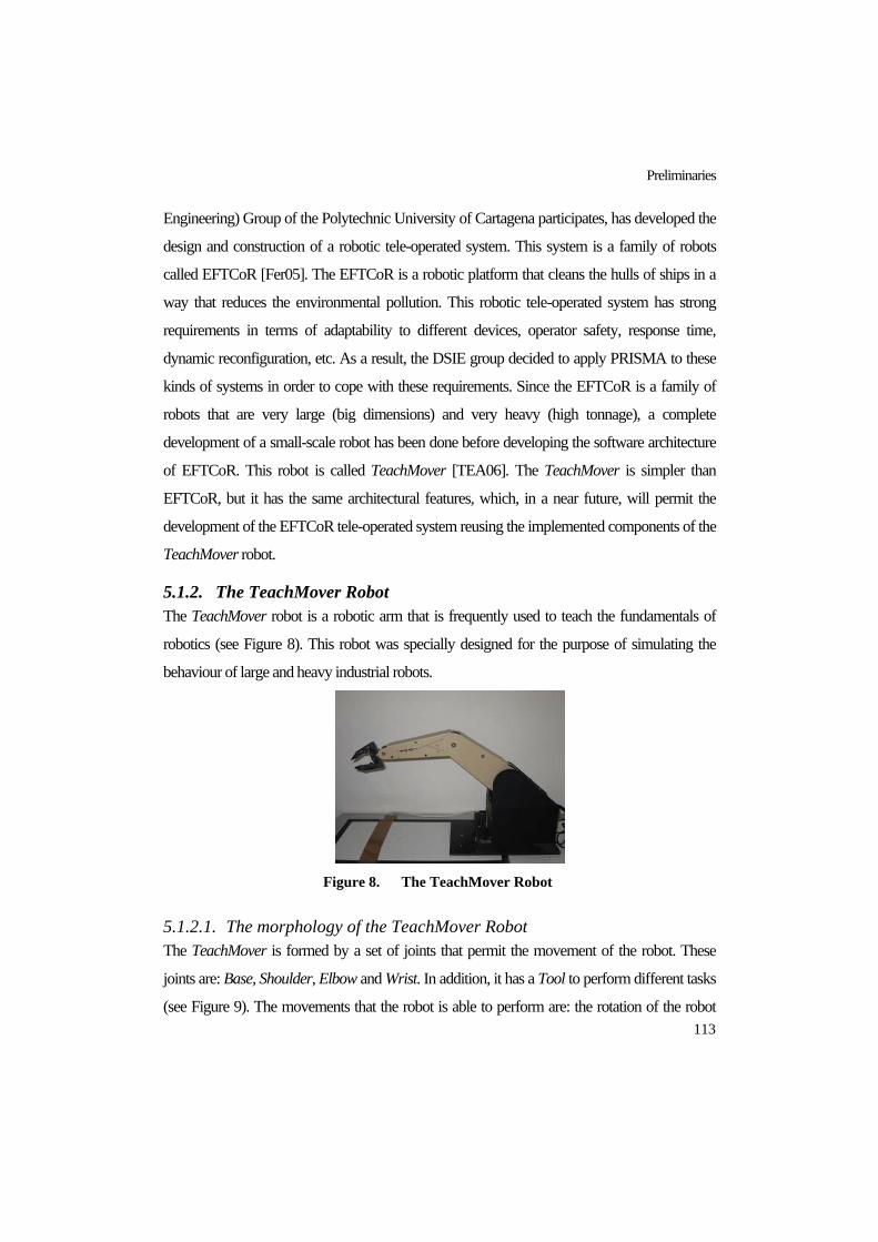
Preliminaries
113
Engineering) Group of the Polytechnic University of Cartagena participates, has developed the
design and construction of a robotic tele-operated system. This system is a family of robots
called EFTCoR [Fer05]. The EFTCoR is a robotic platform that cleans the hulls of ships in a
way that reduces the environmental pollution. This robotic tele-operated system has strong
requirements in terms of adaptability to different devices, operator safety, response time,
dynamic reconfiguration, etc. As a result, the DSIE group decided to apply PRISMA to these
kinds of systems in order to cope with these requirements. Since the EFTCoR is a family of
robots that are very large (big dimensions) and very heavy (high tonnage), a complete
development of a small-scale robot has been done before developing the software architecture
of EFTCoR. This robot is called TeachMover [TEA06]. The TeachMover is simpler than
EFTCoR, but it has the same architectural features, which, in a near future, will permit the
development of the EFTCoR tele-operated system reusing the implemented components of the
TeachMover robot.
5.1.2. The TeachMover Robot The TeachMover robot is a robotic arm that is frequently used to teach the fundamentals of
robotics (see Figure 8). This robot was specially designed for the purpose of simulating the
behaviour of large and heavy industrial robots.
Figure 8. The TeachMover Robot
5.1.2.1. The morphology of the TeachMover Robot The TeachMover is formed by a set of joints that permit the movement of the robot. These
joints are: Base, Shoulder, Elbow and Wrist. In addition, it has a Tool to perform different tasks
(see Figure 9). The movements that the robot is able to perform are: the rotation of the robot

PRISMA: Aspect-Oriented Software Architectures
114
using the base, the articulation of the elbow and shoulder joints, and the rotation of the wrist. In
this case, the Tool is a gripper, whose open and close actions allow the robot to pick up and
deposit objects.
Figure 9. Joints of the TeachMover robot
The robot has six electric step motors for driving the direction of the movements of each
joint. These motors perform the movements through gears that are joined by a cable system.
The TeachMover can be moved at a specific speed by means of half-steps or inverse
cinematics. A half-step movement moves the robot using the number of teeth that a gear of a
joint must be moved as a measure. And, an inverse cinematic movement moves the robot using
a specific point in the space as a measure. These features, together with the features of the
gripper, allow the robot to move objects from an initial position to a final one.
In addition, safety directives of the robot require its movements to be checked to make sure
that they are safe for the robot and the environment that surrounds it. The internal safety of the
robot is preserved by establishing a set of constraints that forbid certain movements that will
break the gears of the robot due to the position of the gears inside the robot. These constraints
are defined by establishing minimum and maximum values for the movements of each joint.
These values are specified in degrees as follows:
Base: ± 90°
Shoulder: + 144°, - 35°
Elbow: + 0° , -149°

Preliminaries
115
Gradient of the Wrist: ± 90°
Rotation of the Wrist: ± 180°
Opening of the gripper: 0 inches, + 3 inches (7,62 cm.)
The robot has a sensor to pick up objects without breaking them. The weight of the objects
that the robot is able to carry when its arm is stretched out is 450 grammes. Furthermore, the
gripper presses the objects with a maximum pressure of 14 Newtons. Finally, the speed of
movements fluctuates between 0 or 7 inches per second (178 mm/s) depending on the load that
the robot carries when the movement is performed.
It is important to mention that the movements of the robot are commanded by an operator
from a computer. This communication between the computer and the robot is possible by
means of the serial/RS232C port. In order to stop the robot in situations of emergency, the
robot has an interruption mechanism for disconnecting the power of the robot by means of
software. This is possible because this interruption mechanism is connected to the parallel port
of the computer.
All these features allow the TeachMover robot to simulate the movements of most of the
industrial tele-operated robots that are currently in use. This robot allows the testing and
verification of new solutions to be applied to more complex robotic systems in the future.
5.1.2.2. The Software Architecture of the TeachMover Robot The TeachMover architecture has different levels of abstraction for its components, connectors
and the interactions among them. The lowest abstraction level of the robot architecture has
sensors and actuators as basic components, which are communicated with the hardware joints
of the robot. The functionality of the actuators and sensors are the following:
Actuator: An actuator sends commands to a joint of the robot. These commands are
performed by the joint or the tool.
Sensor: A sensor reads the results of the commands in order to know whether or not they
have been performed successfully.

PRISMA: Aspect-Oriented Software Architectures
116
Figure 10. Architectural Elements of the TeachMover Software Architecture
An actuator and a sensor are coordinated by means of a connector. These three architectural
elements (actuator, sensor, and SUCconnector) are encapsulated inside a complex component
called the Simple Unit Controller (SUC) (see Figure 10). However, two special SUCs have
been identified in order to take into account the peculiarities of the wrist joint and the tool. The
SUC, the Wrist SUC and the Tool SUC must be composed and coordinated in order to form
the complete structure and functionality of a tele-operated robot. This composition generates
different levels of granularity (see Figure 10):
TeachMover Architecture
RUC
OPERATOR
OperatorConnector
MUC
RUCConnector
Tool
SUC
MUCConnector
Wrist
Actuator
SUCConnector
Sensor
Actuator
WristConnector
Sensor
Actuator
ToolConnector
Sensor
n

Preliminaries
117
Mechanism Unit Controllers (MUCs): This architectural element type represents the
arm of the robot, which is composed of the SUC and Wrist SUC coordinated by means of
a connector.
Robot Unit Controllers (RUCs): This architectural element represents the robot, which is
composed of MUCs and Tool SUCs coordinated by means of a connector.
The Architectural Model: This level represents the interactions between operators and
robots through a connector.
5.2. FORMALISMS Since in this thesis architectural elements are observable processes that have state and
behaviour, the formalisms that are used to formalize the PRISMA model are a Modal Logic of
Actions [Sti92] and π-calculus algebra [Mil93]. π-calculus is used to specify and formalize the
processes of the PRISMA model, and the Modal Logic of Action is used to formalize how the
execution of these processes affects the state of architectural elements.
5.2.1. Modal Logic of Actions A variant of the Modal Logic of Actions presented in [Sti92] is used in this thesis. In addition,
this Modal Logic of Actions has been used for implementing obligations, prohibitions, and
permissions. As a result, it permits the analysis and formulation of assertions of processes that
change the execution environment. A formula of this Modal Logic of Actions is written
following the structure ψ [a] ϕ. ψ and ϕ are well-formed formulae (wff) of the first order of the
logic, which characterize the state before or after the execution of the action a, respectively. ‘[ ]’
is the operator of “need”, and a represents an action. As a result, the meaning of the formulae
that are constructed following the pattern ψ [a] ϕ is the following: “if ψ is satisfied before the
execution of a, ϕ must be satisfied after the execution of a”.
The kinds of formula that are used in this thesis are the following:
ψ [a] false: a cannot be executed in those states in which ψ is satisfied.
ψ [¬a] false: a must be executed in those states in which ψ is satisfied.

PRISMA: Aspect-Oriented Software Architectures
118
ψ [a] ϕ: a can be executed in those states in which ψ is satisfied. If ψ is satisfied before
the execution of a, ϕ must be satisfied after the execution of a.
In this thesis, the Modal Logic of Actions is interpreted using a Kripke structure (Ω, ω0, ρ),
where Ω is a set of possible worlds, ω0 is the initial world, and ρ is the relationship of
accessibility between the worlds (see Figure 11).
Figure 11. Simple Kripke structure
First-order formulae are valid in one world whereas modal logic of actions formulae are
valid in more than one world. This is due to the fact that they are formulae that describe
changes of state. As a result, the Modal Logic of Actions interpreted using a Kripke structure
describes the effects that the execution of a process produces in the state.
5.2.2. π - Calculus The formalism that is used to specify and formalize the processes of the PRISMA model is π-
calculus [Mil93]. It has been selected because it is a model to specify concurrent processes. In
addition, it is an advance over the Calculus of Communicating Systems (CCS) [Mil80] due to
the fact that π-calculus provides mechanisms for specifying mobility and evolution of
concurrent software systems. π-calculus is presented as the best candidate to describe the
processes that are performed in software architectures due to the fact that the computation of
architectural elements is concurrently executed, the configurations of software architectures are
continuously evolving, and architectural elements must be mobile when software architectures
are distributed. For this reason, PRISMA uses π-calculus to specify the protocols (processes)
that architectural elements execute. π-calculus has also been used to formalize the
computational semantics of PRISMA because it provides the necessary primitives to formalize

Preliminaries
119
PRISMA. As a consequence, it is not necessary to introduce a new formalism to formalize the
computational semantics of PRISMA, thus facilitating the understanding of this formalization.
π-calculus is based on the notion of naming. A name can reference different entities such as
an address, an identifier, a pointer, a channel, etc. Unlike object-oriented approaches, the
primitive of π-calculus is the naming of channels, and not the naming of agents. This is a
notable difference because it is not possible to directly reference the name of a process from
another process that wants to communicate with it. The communication between two processes
is only possible if a process references the other process through the name of the channel that
permits the access. Another important property is that the name of the channel should be
unique because names do not have structure; in other words, it is not possible to use the dot
mechanism1 as in object-oriented programming approaches to reference names.
The most widely-known variants of the π-calculus are: monadic π-calculus and polyadic π-
calculus . The former only permits sending a single value through the channel (name), and the
latter permits sending several values through the channel. Polyadic π-calculus is the formalism
that has been chosen to specify the concurrent processes of PRISMA, since the use of polyadic
π-calculus is easier and more flexible than monadic π-calculus.
5.2.2.1. Main Concepts of π-calculus This section presents the main concepts of the original π-calculus, i.e., the main concepts of
monadic π-calculus.
The primitive concept of π-calculus is the name. The other concept that exists in π-calculus
is the process. Processes are built from names by the following syntax:
0|)(|!|||.:: PxPQPPPIi ii νπ∑∈
=
In this definition of a process P, I is a set of indexes and the prefix π, which appears in the
π.P expression, represents an atomic action, exactly the first action that is performed by π.P.
The π prefix can have the three forms that are presented following:
1 ClassName.servicename, ClassName.attributename

PRISMA: Aspect-Oriented Software Architectures
120
x (y) : this prefix means that “input the name y along the link or channel named x”
__x (y): this prefix means that “output the name y along the link or channel named x”
τ : this prefix means silence. It represents an internal action
The operation P | Q, which appears in the definition of P, means that the processes P and Q
are concurrently executed (parallel composition). The operation !P means replication, that
is, to automatically create as many copies as are necessary of the process P (infinite
copies). The operation (νx)P declares a new name call x and its scope is restricted to the
process P. And finally, the process 0 means that it is a null process.
5.2.2.2. PRISMA dialect of π-calculus There are several versions of the π-calculus, as well as variations of the syntax. The version of
π-calculus that has been used in this thesis is not the original version of π-calculus (monadic π-
calculus). In fact, monadic π-calculus is the least used version of π-calculus. This thesis uses a
new version of π-calculus based on polyadic π-calculus and some of its widely used extensions
[Liu95], [San01], [Bar95], [Mil99]. In addition, this version extends the standard polyadic π-
calculus by providing support for priority, which results in the addition of a new action and
modifies the meaning of other actions. Table 3 presents the syntactic conventions that have
been adopted in this version of π-calculus with priorities, some derived operators that have
been defined in other versions, and the new actions that have been defined.
The syntax that has been adopted varies from the syntax of monadic π-calculus presented in
the previous section. The main reason for this change is to facilitate the description and analysis
of the specifications using a standard keyboard. This has been done to avoid symbols above
letters, and symbols that can be confused with each other such as the symbol ‘|’ that represents
the parallel composition operation and the non-deterministic selection operation.
Table 3 shows that the input and output prefixes take the form x?(y) and x!(y), respectively.
The input prefix x?(y) defines the reception of a service request, and the output prefix x!(y)
defines the invocation of a service or the sending of an answer when the is used interanally.
Since the sequence of processes has been expressed by P Q, the continuation of the process

Preliminaries
121
after an input, output, or silence prefixes have also been specified using the symbol , i.e.,
x?(y) P, x!(y) P and τ P, respectively. As a result, the symbol means the sequence of
processes and the sequence of prefixes inside a process.
The original π-calculus does not have a sequence operator due to the fact that π-calculus
does not provide an adequate notion of termination as CSP algebra provides [Hoa85].
However, most of high-level languages present an intuitive notion of sequential composition,
and therefore something similar to this kind of construction should be described in terms of the
π-calculus. As a result, it is quite common to simulate this notion of termination in π-calculus
by using a termination channel as well as the notion of composition of π-calculus. Specifically,
this simulation is obtained by creating processes with the convention of sending a signal
through this termination channel when they finish their execution, and receiving this signal
before they start their execution. This convention is even syntactically enforced in some
languages that are based on π-calculus by providing a specific operator such as Pict [Pie00].
This convention is also adopted in this thesis by providing an operator of sequential
composition. This operator is introduced as a syntactic sugar in the PRISMA dialect in order to
avoid the complexity that the explicit specification of this convention would introduce in the
language. As a result, this operator of sequential composition is not exactly a derived operator,
it is just a syntactic schema that simplifies the specification of processes.
The sequence operator is usually represented by the symbol ‘;’ as in CSP algebra [Hoa85].
But, the PRISMA dialect of π-calculus uses the symbol ‘ ’ because it represents the intuitive
meaning of the compositional sequence better than the symbol ‘;’. The arrow does not only
represent the sequence graphically, but it also depicts its obligatory direction.
As a result, P Q is specified using the PRISMA dialect of π-calculus, it is assumed that
there are two processes are defined as follows:
P1(p) ::= (original definition of P).p!() for p ∉ fn(P) Q1(q) ::= q?(). (original definition of Q) for q ∉ fn(Q)
Finally, what it is meant by this syntactic schema is the following structure:
(νx)(P1(x) | Q1(x))

PRISMA: Aspect-Oriented Software Architectures
122
It must be taken into account that this is a simplified definition due to the fact that the
process P could have several branches. This just tries to present the way in which the definition
works. x,y,z Name ( service, process, parameter, identifier)
>−
x ,>−
y ,>−
z Array of names where x, y , z are parameters
D,E,F Constant
P,Q,R Process
D ::= P
| (x)P Abstraction
| ⟨x⟩P Realization
P ::= 0 Null process
| x?(y) P Input prefix
| x!(y) P Output prefix
| τ P Silence prefix
| (υ x).P Restriction
| P + Q Non-deterministic selection (OR)
| P | | Q Parallel composition
| D (x) Constant application
| *P Replication
| | x=y |P Comparison
| P Q Sequential composition
| if b then P else Q Alternative (derived operator)
| case( b ▷ P Q) Multiple alternative (derived operator)
| (y) : nº P Priority
Table 3. Polyadic π-calculus with priorities
Since this π-calculus version is based on polyadic π-calculus, it is possible to define an
array or tuple of names >−−>−−>−−
zyx ,, in the same way as polyadic π-calculus establishes. As a
result, the input and output prefixes take the form x?(y1…yn) and x!(y1…yn), respectively.

Preliminaries
123
The operation P || Q represents the parallel composition, i.e., P and Q are concurrently
executed. As in other versions, this operation is represented by the symbol ‘||’ instead of the
symbol ‘|’ to avoid possible confusions with the operation OR of other languages. In contrast,
the operation P + Q represents the non-deterministic choice, i.e., either P is executed or Q is
executed. In this operation, the symbol ‘+’ is used instead of the symbol ‘|’ to clearly
distinguish the differences with the symbol ‘||’.
D(x) and *P are interchangeable operators because they define processes with the same
capabilities. The operation D(x) represents the instantiation of the process that represents the
constant D. The operation *P permits the definition of infinite copies of a process without
executing it recursively, as is necessary with the D(x) operation. As in other versions, the
replication operation is represented by the symbol ‘*’ instead of the symbol ‘!’ to avoid
confusions with the output prefix x!(y).
(x)P represents an abstraction operation. This operation can also be expressed with the more
explicit notation (λx1…λxn) P, which is an abstraction of names from a process. This operation
is usually used to define a parametric (abstract) definition of a process (agent). The concretion
( ⟨x⟩P ) is the operation that uses concrete parameters in abstract processes that have been
previously defined using an abstraction operation.
The operation |x =y| P introduces the mechanism to compare two names and only executes
a process when the names are equals. The comparison structures with double (if b then P else
Q) or multiple (case( b ▷ P Q)) alternatives have been derived from this operation. These
structures appear as derived operators of polyadic π-calculus [Mil93] and other extensions of π-
calculus such as [Liu95], [San01]. These two derived structures usually substitute the original
one because they are more expressive.
As mentioned above, this dialect of π-calculus extends the standard π-calculus by
introducing the notion of priority. This extension consists of introducing a new action to specify
priorities. This action emerges from the need to create a mechanism that establishes the priority
of the execution of services that participate in a process through a non-deterministic selection.
This mechanism has already been defined for process algebras, specifically for CCS [Cle01].

PRISMA: Aspect-Oriented Software Architectures
124
Priority is especially necessary in those coordination processes that must take into account
emergency situations and when several invocations of services can arrive at the same time. The
priority action provides the mechanism to define a partial order of the execution of services.
In this thesis, this priority operation has been introduced in π-calculus. This operation is
represented by adding the level of priority after the parameters of the name. The maximum
priority is 0 and the minimum is no constraint, depending on the system and the levels of
priority that the user wants to define. As a result, the way of defining a reception of a service
request or invocation is x ? (y) : nº P and x ! (y) : nº P, respectively. In the case of the
TeachMover, the service stop, which stops the movements of the robot in emergency
situations, has a higher priority than other services of the software system such as the service
moveJoint. The invocation of these services using the π-calculus with priorities is specified as
follows: stop!():0 + moveJoint!(NewSteps, Speed):1
If a priority is not specified, the minimum priority (no constraint) is assumed. Finally, it is
important to note that it is only necessary to define this extension in those systems that require
different levels of priority in the execution of services, such as emergency systems.
5.3. CONCLUSIONS This chapter has detailed the preliminary notions of this thesis. Robotic tele-operated systems
have been chosen as application domain for the PRISMA approach, since these provide real
systems that need real solutions for their development and maintenance processes. Specifically,
PRISMA has been applied to the TeachMover tele-operated robot, which is used to illustrate
the main concepts of PRISMA as well as its methodology.
The formalisms used in this thesis to describe and formalize the PRISMA model have been
presented. The need to represent changes of state in an architectural model as a consequence of
service executions has led us to use a Modal Logic of Actions to formalize this behaviour. The
concurrent nature of processes that are executed in software architecture as well as the evolving
and distributed nature of software architectures have led us to choose the polyadic π-calculus to
describe the protocols of PRISMA and to formalize its execution model. Since complex

Preliminaries
125
software systems sometimes need to prioritize the execution of their services, a dialect of
polyadic π-calculus called polyadic π-calculus with priorities has been defined and adopted in
this thesis.

PRISMA: Aspect-Oriented Software Architectures
126

PART IV
PRISMA
“Computer Software Architecture”, Hermann Wacker [WAC06]


The PRISMA Model
129
CHAPTER 6 6. THE PRISMA MODEL
<< Before a diamond shows its brilliancy and prismatic colours
it has to stand a good deal of cutting and smoothing.>>
Anonymous Author
PRISMA provides a model for the definition of complex software systems. Its main
contributions are the way in which it integrates elements from aspect-oriented software
development and software architecture approaches, as well as the advantages that this
integration provides to software development. The PRISMA model introduces the notion of
aspect following an architectural model with connectors and a symmetrical aspect-oriented
model.
The purpose of this chapter is to define, formalize and exemplify the main concepts of the
PRISMA model. First a brief overview of the PRISMA model is presented and then, each one
of the concepts is formalized and described in detail.
6.1. INTRODUCTION TO THE PRISMA MODEL PRISMA provides a model for the description of software architectures of complex and large
systems. It introduces aspects as first-order citizens of software architectures. This means that,
in PRISMA, aspects are not simulated through other architectural concepts such as connectors,
views or similar mechanisms as in other approaches. PRISMA creates a new concept for
modeling concerns called aspects. As a result, PRISMA specifies different characteristics

PRISMA: Aspect-Oriented Software Architectures
130
(distribution, safety, context-awareness, coordination, etc.) of an architectural element
(component, connector) using aspects.
From the aspect-oriented point of view, PRISMA is a symmetrical model that does not
distinguish a kernel or core entity to encapsulate functionality; functionality is also defined as
an aspect. One concern can be specified by several aspects of a software architecture, whereas a
PRISMA aspect represents a concern that crosscuts the software architecture. This crosscutting
is due to the fact that the same aspect can be imported by more than one architectural element
of a software architecture. In this sense, aspects crosscut those elements of the architecture that
import their behaviour (see Figure 12).
Figure 12. Crosscutting-concerns in PRISMA architectures
The fact that PRISMA is a symmetrical model is an advantage. This facilitates the
construction of software architectures since the model does not manage two different concepts
(class or component, and aspect) in different ways. In addition, the reusability of functional
properties is independent of the architectural element that imports it because the functionality is
specified as an aspect. However, if this functionality were implemented as a kernel class of the
architectural element, the reuse of the functionality would only be achieved by reusing the full

The PRISMA Model
131
architectural element. Consequently, a more uniform model is obtained because of the
homogeneity of the concepts that build an architectural element.
A PRISMA architectural element can be seen from two different views: internal and
external. In the external view, architectural elements encapsulate their functionality as black
boxes and publish a set of services that they offer to other architectural elements (see Figure
13). These services are grouped into interfaces to be published through the ports of architectural
elements. Each port has an associated interface that contains the services that are provided and
requested through the port. As a result, ports are the interaction points of architectural elements.
Figure 13. Black box view of an architectural element
The internal view shows an architectural element as a prism (white box view). Each side of
the prism is an aspect that the architectural element imports. In this way, architectural elements
are represented as a set of aspects (see Figure 14 ) and the weaving relationships among
aspects.
Figure 14. White box view of an architectural element
Since PRISMA is a symmetrical aspect-oriented model that it is applied at the architectural
level, the weaving process does not define the pointcuts between the base code and the aspect
code and their corresponding advices. In PRISMA, there is no base code; all behaviour of the

PRISMA: Aspect-Oriented Software Architectures
132
system is defined as an aspect. As a result, the weaving process is composed of a set of
weavings, and a weaving indicates that the execution of an aspect service can trigger the
execution of services in other aspects. From the AOP point of view PRISMA weavings can be
defined as follows: every service of an aspect is a join point , the services that trigger a weaving
are the pointcuts, and the services that are executed as a consequence of weavings are the
advices. In PRISMA, in order to preserve the independence of the aspect specification from
other aspects and weavings, weavings are specified outside aspects and inside architectural
elements. As a result, aspects are reusable and independent of the context of application and
weavings weave the different aspects that form an architectural element. This way of
specifying weavings achieves not only the reusability of the aspects in different architectural
elements, but also the flexibility of specifying different behaviours of an architectural element
by importing the same aspects and defining different weavings.
The communications between the white box and black box views is possible by means of
interfaces; which are associated to ports and are used by aspects (see Figure 15). Consequently,
a request for a service that arrives to a port of an architectural element is processed by an aspect
that uses the same interface that is used by this port.
Figure 15. Communication between the white box and the black box views
PRISMA has three kinds of architectural elements: components, connectors, and systems.
Components and connectors are simple, but systems are complex components. A component is
an architectural element that captures the functionality of software systems and does not act as a

The PRISMA Model
133
coordinator among other architectural elements; whereas, a connector is an architectural
element that acts as a coordinator among other architectural elements.
Connectors do not have the references of the components that they connect and vice versa.
Thus, architectural elements are reusable and unaware of each other. This is possible due to the
fact that the channels defined between components and connectors have their references
(attachments) instead of architectural elements. Attachments are the channels that enable the
communication between components and connectors. Each attachment is defined by attaching
a component port with a connector port.
Figure 16. Attachments
PRISMA components can be simple or complex. The complex ones are called systems. A
PRISMA system is a component that includes a set of architectural elements (connectors,
components and other systems) that are correctly attached. In addition, a system can have its
own aspects and weavings as components and connectors. Since a system is composed by
other architectural elements, the composition relationships among them must be defined. These
composition relationships are called bindings. Bindings establish the connection among the
ports of the complex component (the system) and the ports of the architectural elements that a
system contains (see Figure 17).
In PRISMA, the dynamics of aspect-oriented architectures are treated at the meta-level. The
meta-level contains the elements that define the PRISMA concepts as data. They can be
created, modified and destroyed through the execution of the services of the meta-level. In this
way, the execution of services is reflected in the architecture by updating this data (the concept
of reflection). As a result, the PRISMA meta-level allows for the creation, destruction and
evolution of architectural elements and aspects as well as the dynamic reconfiguration of
software architectures. The PRISMA meta-level is represented by means of a metamodel that
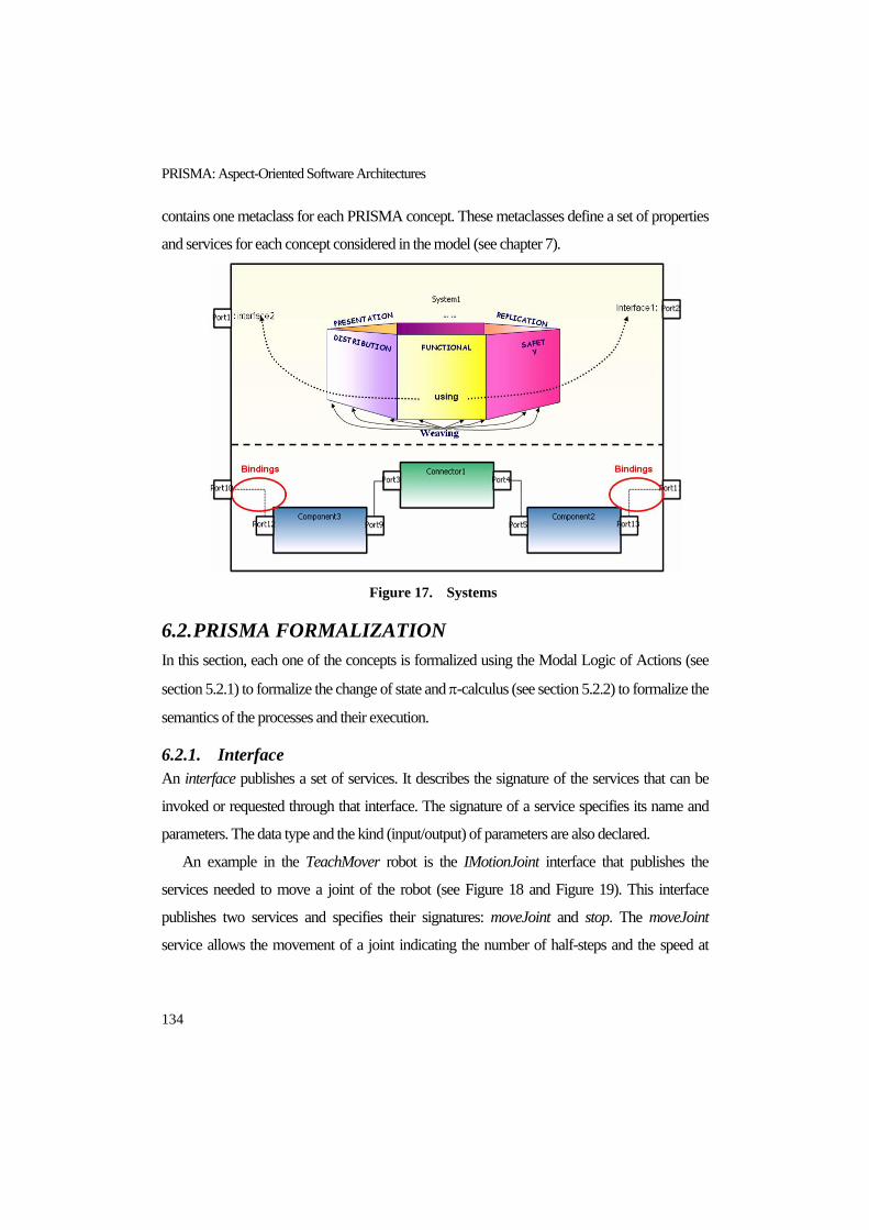
PRISMA: Aspect-Oriented Software Architectures
134
contains one metaclass for each PRISMA concept. These metaclasses define a set of properties
and services for each concept considered in the model (see chapter 7).
Figure 17. Systems
6.2. PRISMA FORMALIZATION In this section, each one of the concepts is formalized using the Modal Logic of Actions (see
section 5.2.1) to formalize the change of state and π-calculus (see section 5.2.2) to formalize the
semantics of the processes and their execution.
6.2.1. Interface An interface publishes a set of services. It describes the signature of the services that can be
invoked or requested through that interface. The signature of a service specifies its name and
parameters. The data type and the kind (input/output) of parameters are also declared.
An example in the TeachMover robot is the IMotionJoint interface that publishes the
services needed to move a joint of the robot (see Figure 18 and Figure 19). This interface
publishes two services and specifies their signatures: moveJoint and stop. The moveJoint
service allows the movement of a joint indicating the number of half-steps and the speed at

The PRISMA Model
135
which the movement must be executed as input parameters. The stop service allows an
emergency stop of the joint.
Figure 18. Specification of the interace IMotionJoint
Figure 19. The interface IMotionJoint
6.2.2. Service A service is a process that executes a set of actions to produce a result. Services can be private
or public; private services are not published by any interface. In addition, they can be simple or
complex. A complex service is composed of a set of services that are executed in a
transactional way (all or nothing), these services are called transactions.
Formalization of Services
Let S be a service. The semantics of S is a process in the polyadic π-calculus, called PS. This
process has a channel CS through which it can be invoked for execution (see Figure 20). We
shall see in section 6.2.6 that services are not invoked directly by other processes but through
weavings that coordinate execution of services within architectural elements.
Figure 20. Formalization of a service
Invocation of services
Interface IMotionJoint
moveJoint (input NewSteps: integer, input Speed: integer);
stop();
End_Interface IMotionJoint;

PRISMA: Aspect-Oriented Software Architectures
136
Let >−
x = x1…xn be the input parameters of S and >−
y = y1…ym be its output parameters. The
invocation of S is formalized by means of an invocation through CS. In addition, each output
parameter yi has a return channel ryi that is created dynamically at each invocation using the
operation restriction of π-calculus (υ). These channels are used to transmit the results of S and
to acknowledge when S has finished executing. As a result, the invocation of a service is
captured by the following process:
(υ yr>−
) (CS !( >−
x , yr>−
) ry1?(y1)…rym?(ym)) Service
The process PS can be divided into the following three actions:
• Reception of requests: The first action of PS must be the reception of the messages that
arrive at CS. This reception is specified as follows:
CS? (>−
x , yr>−
)
• Execution: The execution of PS consists of processing a set of internal actions. These
internal actions create the output parameters (>−
y =y1…ym) and assign them a value.
This internal execution is specified as follows:
(υ >−
y ) (τ)
• End: The last action of PS consists in sending the output parameters (>−
y =y1…ym )
through the return channels ( yr>−
= ry1…rym). In this way, the fact that S has been
executed is confirmed. This end of execution is specified as follows:
ry1!(y1)… rym!(ym)
As a result, the complete formalization of PS is the replicated sequence of these three
actions. This replication allows us to execute the service as many times as it is necessary.

The PRISMA Model
137
PS::= *( CS? (>−
x , yr>−
) (υ >−
y ) ((τ) ry1!(y1)… rym!(ym)))
An example in the Teach Mover robot is the moveJoint service introduced in section 6.2.1.
moveJoint(input NewSteps: integer, input Speed: integer);
As moveJoint does not have output parameters and the system does not need to know when
the service has finished, it does not create new return channels in its invocation. As a result, this
service can be invoked from any entity of the software architecture as follows:
moveJoint!(NewSteps, Speed)
During the execution of the service, requests are received and a set of actions is performed
internally. The latter is captured by the τ expression (silence action see section 5.2.2).
PmoveJoint::= moveJoint?(NewSteps, Speed) τ
Valuations are used to specify the internal process of a service, that is, the operation τ (see
section 6.2.4).
6.2.3. Played_Role A played_role is a process that defines the behaviour of a specific interface. A played role
establishes how and when the services of an interface can be required or provided.
Formalization of Played_Roles
Let PR be a played_role of an interface I. The semantics of PR is a process called PPR that
establishes a partial order for the requests and invocations of the services of I. These
invocations and requests are formalized as in section 6.2.2.
An example in the Teach Mover robot is the played_role ACT for the interface
IMotionJoint (see Figure 21). This played_role defines a non-deterministic selection between
the invocation of stop and moveJoint. This means that when this played_role is used in a port
(see 6.2.5), it restricts the behaviour of the interface to the invocation of its services.

PRISMA: Aspect-Oriented Software Architectures
138
Figure 21. Specification of the played_role ACT
6.2.4. Aspect An aspect defines the structure and the behaviour of a specific concern of the software system.
Examples of concerns are functionality, coordination, safety, distribution, among others.
Structure is defined by a set of attributes, each of which has a value in every state. The state
of the aspect at any given moment is determined by the value of its attributes. An aspect can
define constraints, which must be satisfied during the execution of the aspect.
An aspect declares a number of interfaces and defines a semantics for the services that these
interfaces publish. This semantics captures when the services cannot be executed, how the
execution of services changes the state of the aspect, and the order in which they can be
executed. This semantics is provided by preconditions, valuations and played_roles (see
section 6.2.3), respectively.
An aspect can be private, that is, it does not publish any of its services and it does not define
the semantics of any interface. As a result, this kind of aspect does not specify any played_role
and all its services are private.
An example of a private aspect is SMotion. This safety aspect describes the behaviour that
should be taken into account in order to ensure the safety of the Teach Mover robot, the safety
of operators that control it, and the safety the environment that surrounds them. As it can be
seen in Figure 22, this aspect does not import any interface because it is private.
Figure 22. The private aspect SMotion
An example of a public aspect is the coordination aspect CProcessSuc (see Figure 23) that
describes the behaviour required to synchronize the actuator and the sensor of a joint in order to
Safety Aspect SMotion
… …
End_Aspect SMotion;
ACT for IMotionJoint = moveJoint ! (NewSteps, Speed) + stop !();

The PRISMA Model
139
move the hardware joint. This aspect uses four interfaces to provide this behaviour:
IMotionJoint to request that a joint be moved, IRead to know whether the joint has moved or
not, IJoint to receive requests for movements and to notify what happened with the request, and
IPosition to query and update the position of the joint.
Figure 23. The public aspect CProcessSuc
The behaviour of an aspect is defined by means of a protocol. When an aspect is public, the
protocol describes how the different played_roles and private services are coordinated. When
an aspect is private, the protocol coordinates the different private services that are specified in
the aspect.
The different concerns that have to be taken into account in a software system vary
depending on the domain. Those concerns that crosscut the software system are defined as
aspects. The domains in which PRISMA has been applied allow the following kinds of aspects
to be considered:
Functional Aspect: A functional aspect captures the semantics of the information system
by defining its attributes and behaviour.
Coordination Aspect: A coordination aspect defines how architectural elements are
synchronized while they communicate with each other.
Safety Aspect: A safety aspect specifies the safe values and strategies to apply in order to
ensure the accurate and safe execution of the software system.
Distribution Aspect: A distribution aspect specifies the features and strategies that are
related to its distributed communication by means of patterns [Ali03]. A distribution aspect
specifies the site where the architectural element is located and indicates when an element
needs to be moved [Ali05a]
Coordination Aspect CProcessSuc using IMotionJoint,
IRead, IJoint, IPosition
… …
End_Aspect CProcessSuc;

PRISMA: Aspect-Oriented Software Architectures
140
Contex-Awareness Aspect: A context-awareness aspect provides context-information
and supports inspection in order to retrieve the structural properties of the provided
information [Jae03].
Mobility Aspect: A mobility aspect provides mobility services to architectural elements in
order to be mobile or to move other architectural elements [Ali06], [Ali05b].
Integration Aspect: An integration aspect allows the integration of COTS components
(Commercial Off-The-Shelf) in PRISMA software architectures in an abstract way.
This thesis is focused on the functional, coordination, safety, and integration aspects. They
are the aspects that have been used in the TeachMover.
Formalization of Aspects
An aspect is defined by the tuple (A, X, Φ, Π):
A: a set of attributes
X: a set of services (see section 6.2.2)
Φ: a set of formulae in modal logic of actions
Π: a set of terms in π-calculus
Formalization of Φ
Φ is a set of formulae in modal logic of actions. These formulae define how and when the
services of an aspect (X) change the value of the attributes of the aspect (A). They are
valuations, preconditions and constraints.
Valuations: Valuations define the change of the state of an aspect when one of its services
is executed. They are formalized by the following formula:
ψ [a] ϕ
This means that if ψ is satisfied before the execution of a, ϕ must be satisfied after
the execution of a. ψ and ϕ are wff that make reference to the states before and after
the execution of a, respectively. As a result, valuations define the internal process of a
service (τ, see section 6.2.2 ).
The FJoint aspect defines a service newPosition, its valuation consists in storing
the position of the joint (see Figure 24). In this valuation, the ψ wff is empty because it

The PRISMA Model
141
is not necessary for defining the state before the execution of moveJoint. The ϕ wff is
defined by the expression halfSteps := halfSteps + NewSteps. ϕ establishes that the
attribute halfSteps will have the value of the halfSteps and NewSteps2 addition after
the moveJoint execution.
Figure 24. Specification of the valuation of the service moveJoint
Preconditions: Preconditions define prohibitions of the execution of actions. They are
formalized by the following formula:
¬ψ [a] false
This means that if ψ is not satisfied, a cannot be executed; it is prohibited. ψ is a
wff that expresses a condition on the state of the aspect.
In the case of the service newPosition, its precondition establishes that the service
newPosition can only be executed when the attribute validMovement has the value
true (see Figure 25).
Figure 25. Specification of the precondition of the service newPosition
Constraints: Constraints are conditions that must be satisfied throughout the entire
execution process of the aspect. They can be classified into static or dynamic. Static
constraints make reference to one state of the aspect whereas dynamic constraints make
reference to several states of the aspect. They use operators of temporal logic: always3 for
2 The operator “:=” is used for the ϕ formula instead of using the operator “=”because it can be interpreted more intuitively. 3 If there is a formula without a temporal operator, its assumed that the semantics of the formula is the semantics of the operator always.
Preconditions
newPosition(NewSteps) if (validMovement = true)
in/out moveJoint(input NewSteps: integer, input Speed: integer);
Valuations
[in moveJoint (NewSteps, Speed)]
tempHalfSteps := NewSteps;

PRISMA: Aspect-Oriented Software Architectures
142
static constraints, and sometimes, since, next or until for dynamic constraints. They are
formalized by the following formulae:
always ψ, sometimes ψ, ψ since ψ’, ψ next ψ’, ψ until ψ’
Formalization of Π
Let A be a public aspect whose behaviour is specified by played_roles PR1…PRn and the
protocol PRT1. Its semantics is the process PA defined as follows:
PA::= PR1 || … || PRn || PRT1
This means that the played_roles and the protocol of a public aspect are processes that are
executed concurrently. For this reason, PA is defined as their parallel composition. During this
concurrent execution, the protocol communicates with the played_roles and the private services
of the aspect in order to synchronize them.
Let PRA be a private aspect whose behaviour is specified by the PRT1 protocol. Its
semantics is the process PPRA defined as follows:
PPRA ::= PRT1
This means that the process of a private aspect is its protocol. This is because, as already
mentioned, a private aspect does not have played_roles and its protocol only synchronizes the
private services of the aspects.
6.2.5. Port Ports are the interaction points of architectural elements (components and connectors). Every
port has a type, which is an interface whose behaviour is specified by a played_role for that
interface. This played_role (see section 6.2.3) has to be defined in one of the aspects of the
corresponding architectural element.
Formalization of Ports
Let P be a port of an architectural element whose behaviour is specified by the played_role
PR1 (see section 6.2.3) of an aspect corresponding to the architectural element. Its semantics is
the process PP defined as follows:

The PRISMA Model
143
PP ::= PR1
This means that the process of a port is its played_role.
An example is the port PAct (see Figure 26). It belongs to one of the architectural elements
of the TeachMover system. This port is typed by the IMotionJoint interface and the ACT
played_role, which is defined in the CProcessSuc coordination aspect.
Figure 26. Specification of the port PAct
6.2.6. Weaving A weaving specification defines how the execution of a service of an aspect can trigger the
execution of a service of another aspect. The same service can be involved in several weavings.
In order to preserve the independence of the aspect specification from other aspects and
weavings, weavings are specified outside aspects and inside architectural elements. As a result,
weavings coordinate the different aspects that an architectural element imports.
A weaving is defined by means of operators that describe the order in which services are
executed.
A weaving that relates service s1 of aspect A1 and service s2 of aspect A2 can be specified
using the following operators:
A2.s2 after A1.s1: A2.s2 is executed after A1.s1
A2.s2 before A1.s1: A2.s2 is executed before A1.s1
A2.s2 instead A1.s1: A2.s2 is executed in place of A1.s1
A2.s2 afterif (Boolean condition) A1.s1: A2.s2 is executed after A1.s1 if the condition is
satisfied.
A2.s2 beforeif (Boolean condition) A1.s1: if the condition is satisfied, A2.s2 is executed
followed by A1.s1; otherwise, only A2.s2 is executed.
Ports
PAct: IMotionJoint,
Played_Role CProcessSuc.ACT;
… …
End_Port;

PRISMA: Aspect-Oriented Software Architectures
144
A2.s2 insteadif (Boolean condition) A1.s1: A2.s2 is executed in place of A1.s1 if the
condition is satisfied.
The invocation of A1.s1, the second argument of the weaving, triggers the execution of
weaving (pointcut). When a weaving is specified, the operator is chosen from the trigger
service point of view; depending on whether the trigger service needs the execution of a service
before, after, or instead of it (advice).
Formalization of Weavings
The semantics of a weaving is a process that intercepts the invocation of a service A1.s1
and either replaces it with, or executes it in relation to, another service A2.s2. A1.s1 and A2.s2
belong to different aspects.
The weaving must be executed each time that A1.s1 is invoked, upon which it executes
either A2.s2 instead of A1.s1 or A1.s1 and A2.s2 in the correct order. This means that the
invocation of a service does not automatically trigger the execution of its associated process. In
terms of our formalization in π-calculus, and given a service S that the weaving is controlling,
the weaving process PW interacts with PS via the channel CS defined in 6.2.2 and provides a
channel CwS that other processes can use to invoke S (see Figure 27).
Figure 27. Formalization of a service controlled by a weaving
Taking into account these two channels, the invocation of S by the weaving process is as
follows:
(υ yr>−
)(CS !( >−
x , yr>−
) ry1?(y1)…rym?(ym))
The invocation of S by other processes is as follows:
(υ yr>−
) (CwS ! ( >−
x , yr>−
) ry1?(y1)…rym?(ym))

The PRISMA Model
145
Each weaving operator defines a process with a specific behaviour. The processes
associated with the operators are specified as follows:
A2.s2 after A1.s1
Let AW be A2.s2 after A1.s1. Its semantics is the process PAW defined as follows:
P1..n ::= (υ yr>−
) (CwA1_s1 ! ( >−
x , yr>−
) ry1?(y1)…rym?(ym))
PAW::= *(CwA1_s1? ( >−
x , yr>−
) (υ 1sr>−
) (CA1_s1! ( >−
x , 1sr>−
) rs11?( s11)… rs1m?( s1m))
(υ 2sr>−
) (CA2_s2! ( >−
x , 2sr>−
) rS21?(s21)… rS2m?(s2m)) ry1 ! (s11)… rym ! (s1m))
PA1_s1::= *(CA1_s1? (>−
x , 1sr>−
) (υ 1
>−
s ) ((τ) rs11!(s11)… rs1m!(s1m)))
PA2_s2::= *(CA2_s2? (>−
x , 2sr>−
) (υ 2
>−
s ) ((τ) rs21!(s21)… rs2m!(s2m)))
This means that PAW receives the invocation of A1.s1 from another process (P1..n) through
CwA1_s1. Because AW is an “after” weaving, PAW starts by invoking A1.s1 using CA1_s1. Then,
PA1_s1 receives the invocation, executes a set of internal actions, sends the results, and notifies
the weaving that execution has finished. Next, the second service of the weaving is executed:
PAW invokes A2.s2 using CA2_s2, and PA2_s2 receives the invocation upon which it executes a set
of internal actions, sends the results, and notifies the weaving that execution has finished.
Finally, PAW sends the results to the process that invoked A1.s1.

PRISMA: Aspect-Oriented Software Architectures
146
A2.s2 before A1.s1
Let BW be A2.s2 before A1.s1. Its semantics is the process PBW defined as follows:
P1..n ::= (υ yr>−
) (CwA1_s1 ! ( >−
x , yr>−
) ry1?(y1)…rym?(ym))
PBW::= *(CwA1_s1? ( >−
x , yr>−
) (υ 2sr>−
) (CA2_s2! ( >−
x , 2sr>−
) rS21?(s21)… rS2m?(s2m))
(υ 1sr>−
) (CA1_s1! ( >−
x , 1sr>−
) rs11?( s11)… rs1m?( s1m)) ry1 ! (s11)… rym ! (s1m))
PA1_s1::= *(CA1_s1? (>−
x , 1sr>−
) (υ 1
>−
s ) ((τ) rs11!(s11)… rs1m!(s1m)))
PA2_s2::= *(CA2_s2? (>−
x , 2sr>−
) (υ 2
>−
s ) ((τ) rs21!(s21)… rs2m!(s2m)))
This means that PBW receives the invocation of A1.s1 from another process (P1..n) through
CwA1_s1. Because BW is a “before” weaving, PBW starts by invoking A2.s2 using CA2_s2. Then,
PA2_s2 receives the invocation, executes a set of internal actions, sends the results and notifies the
weaving that execution has finished. Next, PBW invokes A1.s1 using CA1_s1, and PA1_s1 receives
the invocation upon which it executes a set of internal actions, sends the results, and notifies the
weaving that the execution has finished. Finally, PBW sends the results to the process that
invoked A1.s1.

The PRISMA Model
147
A2.s2 instead A1.s1
Let IW be A2.s2 instead A1.s1. Its semantics is the process PIW defined as follows:
P1..n ::= (υ yr>−
) (CwA1_s1 ! ( >−
x , yr>−
) ry1?(y1)…rym?(ym))
PIW::= *(CwA1_s1? ( >−
x , yr>−
) (υ 2sr>−
) (CA2_s2! ( >−
x , 2sr>−
) rS21?(s21)… rS2m?(s2m))
ry1 ! (s21)… rym ! (s2m))
PA1_s1::= *(CA1_s1? (>−
x , 1sr>−
) (υ 1
>−
s ) ((τ) rs11!(s11)… rs1m!(s1m)))
PA2_s2::= *(CA2_s2? (>−
x , 2sr>−
) (υ 2
>−
s ) ((τ) rs21!(s21)… rs2m!(s2m)))
This means that PIW receives the invocation of A1.s1 from another process (P1..n) through
CwA1_s1. Because IW is an “instead” weaving, PIW invokes A2.s2 instead of A1.s1, PIW invokes
A2.s2 using CA2_s2. Next, PA2_s2 receives the invocation, executes a set of internal actions, sends
the results, and notifies the weaving that execution has finished. Finally, PIW sends the results to
the process that invoked A1.s1.
A2.s2 afterif (boolean_condition) A1.s1
Let AWIF be A2.s2 afterif (Boolean_condition) A1.s1. Its semantics is the process PAWIF
defined as follows:

PRISMA: Aspect-Oriented Software Architectures
148
P1..n ::= (υ yr>−
) (CwA1_s1 ! ( >−
x , yr>−
) ry1?(y1)…rym?(ym))
PAWIF::= *(CwA1_s1? ( >−
x , yr>−
) (υ 1sr>−
) (CA1_s1! ( >−
x , 1sr>−
) rs11?( s11)… rs1m?( s1m))
if (boolean_condition = true) then
(υ 2sr>−
) (CA2_s2! ( >−
x , 2sr>−
) rS21?(s21)… rS2m?(s2m)) ry1 ! (s11)… rym ! (s1m)) else ry1 ! (s11)… rym ! (s1m))
PA1_s1::= *(CA1_s1? (>−
x , 1sr>−
) (υ 1
>−
s ) ((τ) rs11!(s11)… rs1m!(s1m)))
PA2_s2::= *(CA2_s2? (>−
x , 2sr>−
) (υ 2
>−
s ) ((τ) rs21!(s21)… rs2m!(s2m)))
This means that PAWIF receives the invocation of A1.s1 from another process (P1..n) through
CwA1_s1. Because AWIF is an “after” weaving, PAWIF starts by invoking A1.s1 using CA1_s1.
Then, PA1_s1 receives the invocation, executes a set of internal actions, sends the results, and
notifies the weaving that execution has finished. Since, the AWIF is a conditional weaving, it
has an associated condition. Next, if the boolean condition of the AWIF is true, the second
service of the weaving is executed; otherwise PAWIF sends the results to the process that invoked
A1.s1. In the first case, when the condition is satisfied, PAWIF invokes A2.s2 using CA2_s2 and
PA2_s2 receives the invocation upon which it executes a set of internal actions, sends the results,

The PRISMA Model
149
and notifies the weaving that execution has finished. Finally, PAWIF sends the results to the
process that invoked A1.s1.
A2.s2 beforeif (boolean_condition) A1.s1
Let BWIF be A2.s2 beforeif (Boolean_condition) A1.s1. Its semantics is the process PBWIF
defined as follows:
P1..n ::= (υ yr>−
) (CwA1_s1 ! ( >−
x , yr>−
) ry1?(y1)…rym?(ym))
PBWIF::= *(CwA1_s1? ( >−
x , yr>−
) (υ 2sr>−
) (CA2_s2! ( >−
x , 2sr>−
) rS21?(s21)… rS2m?(s2m))
if (boolean_condition = true) then
(υ 1sr>−
) (CA1_s1! ( >−
x , 1sr>−
) rs11?( s11)… rs1m?( s1m)) ry1 ! (s11)… rym ! (s1m)) else ry1 ! (s21)… rym ! (s2m))
PA1_s1::= *(CA1_s1? (>−
x , 1sr>−
) (υ 1
>−
s ) ((τ) rs11!(s11)… rs1m!(s1m)))
PA2_s2::= *(CA2_s2? (>−
x , 2sr>−
) (υ 2
>−
s ) ((τ) rs21!(s21)… rs2m!(s2m)))
This means that PBWIF receives the invocation of A1.s1 from another process (P1..n) through
CwA1_s1. Because BWIF is a “before” weaving, PBWIF starts by invoking A2.s2 using CA2_s2.
Then, PA2_s2 receives the invocation, executes a set of internal actions, sends the results, and
notifies the weaving that execution has finished. Next, if the boolean condition of the BWIF is

PRISMA: Aspect-Oriented Software Architectures
150
true, the first service of the weaving is executed; otherwise PBWIF sends the results of A2.s2 to
the process that invoked A1.s1. In the first case, when the condition is satisfied, PBWIF invokes
A1.s1 using CA1_s1 and PA1_s1 receives the invocation upon which it executes a set of internal
actions, sends the results, and notifies the weaving that the execution has finished. Finally,
PBWIF sends the results of A1.s1 to the process that invoked A1.s1.
A2.s2 insteadif (boolean_condition) A1.s1
Let IWIF be A2.s2 insteadif (Boolean_condition) A1.s1. Its semantics is the process PIWIF
defined as follows.
P1..n ::= (υ yr>−
) (CwA1_s1 ! ( >−
x , yr>−
) ry1?(y1)…rym?(ym))
PIWIF::= *(CwA1_s1? ( >−
x , yr>−
)
if (boolean_condition = true) then
(υ 2sr>−
) (CA2_s2! ( >−
x , 2sr>−
) rS21?(s21)… rS2m?(s2m)) ry1 ! (s21)… rym ! (s2m)) else
(υ 1sr>−
) (CA1_s1! ( >−
x , 1sr>−
) rs11?( s11)… rs1m?( s1m)) ry1 ! (s11)… rym ! (s1m))
PA1_s1::= *(CA1_s1? (>−
x , 1sr>−
) (υ 1
>−
s ) ((τ) rs11!(s11)… rs1m!(s1m)))
PA2_s2::= *(CA2_s2? (>−
x , 2sr>−
) (υ 2
>−
s ) ((τ) rs21!(s21)… rs2m!(s2m)))
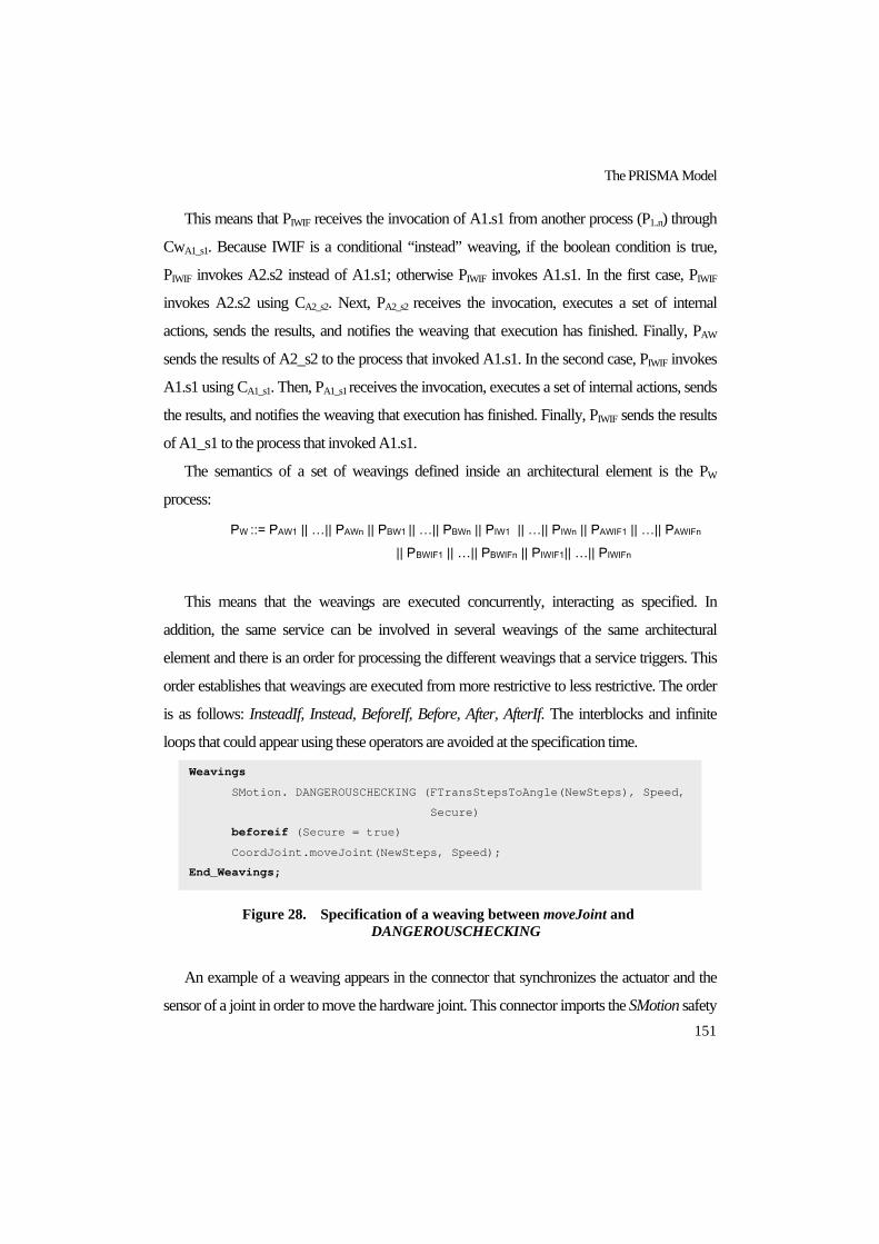
The PRISMA Model
151
This means that PIWIF receives the invocation of A1.s1 from another process (P1..n) through
CwA1_s1. Because IWIF is a conditional “instead” weaving, if the boolean condition is true,
PIWIF invokes A2.s2 instead of A1.s1; otherwise PIWIF invokes A1.s1. In the first case, PIWIF
invokes A2.s2 using CA2_s2. Next, PA2_s2 receives the invocation, executes a set of internal
actions, sends the results, and notifies the weaving that execution has finished. Finally, PAW
sends the results of A2_s2 to the process that invoked A1.s1. In the second case, PIWIF invokes
A1.s1 using CA1_s1. Then, PA1_s1 receives the invocation, executes a set of internal actions, sends
the results, and notifies the weaving that execution has finished. Finally, PIWIF sends the results
of A1_s1 to the process that invoked A1.s1.
The semantics of a set of weavings defined inside an architectural element is the PW
process:
PW ::= PAW1 || …|| PAWn || PBW1 || …|| PBWn || PIW1 || …|| PIWn || PAWIF1 || …|| PAWIFn || PBWIF1 || …|| PBWIFn || PIWIF1|| …|| PIWIFn
This means that the weavings are executed concurrently, interacting as specified. In
addition, the same service can be involved in several weavings of the same architectural
element and there is an order for processing the different weavings that a service triggers. This
order establishes that weavings are executed from more restrictive to less restrictive. The order
is as follows: InsteadIf, Instead, BeforeIf, Before, After, AfterIf. The interblocks and infinite
loops that could appear using these operators are avoided at the specification time.
Figure 28. Specification of a weaving between moveJoint and DANGEROUSCHECKING
An example of a weaving appears in the connector that synchronizes the actuator and the
sensor of a joint in order to move the hardware joint. This connector imports the SMotion safety
Weavings
SMotion. DANGEROUSCHECKING (FTransStepsToAngle(NewSteps), Speed,
Secure)
beforeif (Secure = true)
CoordJoint.moveJoint(NewSteps, Speed);
End_Weavings;

PRISMA: Aspect-Oriented Software Architectures
152
aspect and the CProcessSUC coordination aspect presented in 6.2.4. The need for a weaving
emerges due to the fact that a joint is moved only after the connector is sure that a movement is
safe. The invocation of the moveJoint service (the second argument of the weaving) of
CProcessSUC triggers the execution of the weaving (see section 6.2.2). The weaving of the
connector implies that the DANGEROUSCHECKING service of SMotion will be executed
before the moveJoint service of CProcessSUC. The condition also establishes that the
execution of moveJoint must only be performed if the Secure parameter of
DANGEROUSCHECKING returns true (see Figure 28).
6.2.7. Architectural Element An architectural element is formed by a set of aspects, their weaving relationships, and one or
more ports. These ports represent interaction points among architectural elements. There are
two kinds of architectural elements, components and connectors.
Formalization of Architectural Elements
Let AR be an architectural element, A1…An the aspects that it imports, P1...Pm its ports, and
W its set of weavings.
AR is defined by the tuple (A, X, Φ, Π):
A: the union of the attributes of the aspects A1…An
X: the union of the services of the aspects A1…An
Φ: the union of the formulae in modal logic of actions of the aspects A1…An
Π: the process PAR defined as follows:
PAR ::= PP1 ||…|| PPm || PA1 || …|| PAn || PW
This means that the processes of the ports, weavings and aspects of the architectural
element are executed concurrently. For this reason, PAR is defined as their parallel composition.
6.2.8. Connector A connector is an architectural element that acts as a coordinator between other architectural
elements. As such, connectors have a coordination aspect.

The PRISMA Model
153
An example is the CnctJoint that synchronizes the Actuator and the Sensor of a joint (see
Figure 29). This connector imports the SMotion safety aspect and the CProcessSuc
coordination aspect as mentioned above and is formed by the follow set of ports and weavings
(see Figure 30):
Figure 29. The CnctJoint connector
Figure 30. Specification of the connector CnctJoint
Connector CnctJoint
Coordination Aspect Import CProcessSuc;
Safety Aspect Import SMotion;
Weavings
SMotion. DANGEROUSCHECKING(NewSteps, Speed, Secure)
beforeif (Safe = true)
CProcessSuc.movejoint(NewSteps, Speed);
End_Weavings;
Ports
PAct : IMotionJoint,
Played_Role CProcessSuc.ACT;
PSen : IRead,
Played_Role CProcessSuc.SEN;
PJoint : IJoint,
Played_Role CProcessSuc.JOINT;
PPos : IPosition,
Played_Role CProcessSuc.POS;
End_Ports
… …
End Connector CnctJoint;

PRISMA: Aspect-Oriented Software Architectures
154
6.2.9. Component A component is an architectural element that captures a given functionality of a software
system. As such, components do not have a coordination aspect.
An example is the Actuator (see Figure 31). It sends commands to a joint of the robot.
These commands are performed by the joint or the tool. The Actuator of the TeachMover only
imports a functional aspect (see Figure 32).
Figure 31. The component Actuator
Figure 32. Specification of the component Actuator
6.2.10. Attachment An attachment establishes a connection between two architectural elements, more precisely,
between a port of a component and a port of a connector.
An attachment is a channel that transmits the invocations and results of services from one port
to another. It solves mismatches of service names and ensures compatibility of played_roles.
Played_roles are compatible if:
They define the semantics of the same interface or one interface is a subset of the other.
They can communicate with each other, i. e., at least one service requested by one of the
played_roles must be provided by the other.
Component Actuator
Integration Aspect Import RS232;
Ports
PCoord : IMotionJoint,
Played_Role RS232.INTMOVE;
End_Ports;
… …
End_Component Actuator;

The PRISMA Model
155
Formalization of Attachments
Let ATCH be an attachment that connects ports PC and PCnct. Let PC be the port of a
component and PCnct the port of a connector. The semantics of PC and PCnct is defined by
two played_roles called PRPC and PRPCnct, respectively (see section 6.2.5). Let CS1…CSn and
CnS1…CnSm be the services that participate in PRPC and PRPCnct , respectively. The
formalization of PRPC and PRPCnct is defined as in section 6.2.3. As a result, the semantics of
PRPC is a process that establishes a partial order for the requests and invocations of the services
CS1…CSn through the channels CcS1…CcSn.The semantics of PRPCnct is a process that
establishes a partial order for the requests and invocations of the services CnS1…CnSm through
the channels CcnS1…CnSm. The semantics of ATCH is a process called PATCH. PATCH
coordinates the services of PRPC and PRPCnct through the channels that these services provide
(see section 6.2.2) (see Figure 33).
Figure 33. Formalization of Attachments
The formalization of ATCH is presented in two steps as follows:
1. Invocation from the component
The process that formalizes the behaviour of Cs when the component invokes a service is
defined as follows:
Pcs ::= … (υ yrpc>−
) (CcS1 !( >−
x , yrpc>−
) rpcy1?(y1)… rpcym?(ym))
|| … ||
(υ yrpc>−
) (CcSn !( >−
x , yrpc>−
) rpcy1?(y1)… rpcym?(ym))…
The process that formalizes the behaviour of Cns when the component invokes a service is
defined as follows:
Pcns ::= … CcS1 ?( >−
x , yr>−
) (υ>−
y ) ((τ) ry0!(y0)… rym!(ym))

PRISMA: Aspect-Oriented Software Architectures
156
|| … ||
CcSn ?( >−
x , yr>−
) (υ>−
y ) ((τ) ry0!(y0)… rym!(ym)) …
The process that formalizes the behaviour of ATCH when the invocation of services is
executed from a component is defined as follows:
PATCH ::= CcS1 ? ( >−
x , yrpc>−
) (υ yr>−
) (CcnS1 ! ( >−
x , yr>−
)
ry0?(y0)… rym?(ym)) rpcy0!(y0)…rpcym!(ym) || … ||
CcSn ?( >−
x , yrpc>−
) (υ yr>−
) (CcnSm ! (>−
x , yr>−
)
ry0?(y0)… rym?(ym)) rpcy0!(y0)…rpcym!(ym) … …
This means that the process receives the invocations from PC and sends the invocation of
the services with the correct name to PCnct in a concurrent way.
2. Invocation from the connector
The process that formalizes the behaviour of Cs when the connector invokes a service is
defined as follows:
Pcs ::= … (CcS1 ?( >−
x , yrpc>−
) (υ>−
y ) ((τ) rpcy1!(y1)… rpcym!(ym))
|| … ||
CcSn ?( >−
x , yrpc>−
) (υ>−
y ) ((τ) rpcy1!(y1)… rpcym!(ym))…
The process that formalizes the behaviour of Cns when the connector invokes a service is
defined as follows:
Pcns ::= … (υ yr>−
) (CcS1 !( >−
x , yr>−
) ry0?(y0)… rym?(ym))
|| … ||
(υ yr>−
) (CcSn !( >−
x , yr>−
) ry0?(y0)… rym?(ym)) …

The PRISMA Model
157
The process that formalizes the behaviour of ATCH when the invocation of services is
executed from a connector is defined as follows:
PATCH ::= CcnS1? (>−
x , yr>−
) (υ yrpc>−
) (CcS1 !( >−
x , yrpc>−
)
rpcy0?(y0)…rpcym?(ym)) ry1!(y1)…rym!(ym) || … ||
CcnSn? (>−
x , yr>−
) (υ yrpc>−
) (CcSn !( >−
x , yrpc>−
)
rpcy0?(y0)…rpcym?(ym)) ry1!(y1)…rym!(ym) … …
This means that the process receives the invocations from PCnct and sends the invocation of
the services with the correct name to PC in a concurrent way.
PATCH defines the parallel composition between the processes that define the behaviour of
ATCH when the invocation is from a connector and from a component. The process PATCH is
defined as follows:
PATCH ::= CcS1 ? ( >−
x , yrpc>−
) (υ yr>−
) (CcnS1 ! ( >−
x , yr>−
)
ry0?(y0)… rym?(ym)) rpcy0!(y0)…rpcym!(ym) || … ||
CcSn ?( >−
x , yrpc>−
) (υ yr>−
) (CcnSm ! (>−
x , yr>−
)
ry0?(y0)… rym?(ym)) rpcy0!(y0)…rpcym!(ym) … … || …||
CcnS1? (>−
x , yr>−
) (υ yrpc>−
) (CcS1 !( >−
x , yrpc>−
)
rpcy0?(y0)…rpcym?(ym)) ry1!(y1)…rym!(ym)|| … ||
CcnSn? (>−
x , yr>−
) (υ yrpc>−
) (CcSn !( >−
x , yrpc>−
)
rpcy0?(y0)…rpcym?(ym)) ry1!(y1)…rym!(ym) … …
An example of attachment is the channel that connects the Actuator (see Figure 31) and the
CnctJoint (see Figure 29) (see Figure 35 and Figure 34).

PRISMA: Aspect-Oriented Software Architectures
158
Figure 34. Specification of an attachment between the Actuator and the
CnctJoint
Figure 35. The attachment between the Actuator and the CnctJoint
The channel connects the ports PCoord and PAct, which are defined in the Actuator (see
Figure 32) and the CnctJoint (see Figure 30), respectively. Their played_roles INTMOVE and
ACT of PCoord and PAct are specified in Figure 36. In addition, the minimum and maximum
cardinalities of the attachment are specified. They define the connection pattern by constraining
the minimum and maximum instances of the attachment. These cardinalities can be defined as
follows:
connector.port (min, max) component.port(min, max)
connector.port (min, max) defines how many instances of the attachment can be
connected to one instance of the connector through the port
component.port(min, max) defines how many instances of the attachment can be
connected to one instance of the component through the port.
For example, the semantics of CnctJoint.PAct(1,1) is that an instance of the connector
CnctJoint must have one and only one attachment of this type connected to the port CoorAct,
and the semantics of Actuator.PCord(1,1) is that an instance of the component Actuator must
have one and only one attachment of this type connected to the port RobotAct.
Attachments
AttchActCnct: CnctJoint.PAct(1,1)<--> Actuator.PCoord(1,1);
… …
End_Attachements;

The PRISMA Model
159
Figure 36. Specification of played_roles ACT and ROBOT
The process of the attachment that connects both played_roles is the following:
stop!() stop?() ||
moveJoint!(Newsteps, Speed) movejoint? (NewSteps, Speed)
6.2.11. Binding A binding relationship defines the composition between a complex component and one of its
architectural elements, specifically, between a port of a complex component and a port of one
of its architectural elements. In PRISMA, complex components are called systems (see 6.2.12).
A binding is a relay, a channel that redirects the invocations and results of services from one
port to another. It solves mismatches of service names and ensures the compatibility of
played_roles. Played_roles are compatible if:
They define the semantics of the same interface, or one interface is a subset of the other
one.
They can communicate with each other, i. e., at least one service requested by one of the
played_roles must be requested by the other, or one service provided by one of the
played_roles must be provided by the other.
Formalization of Bindings
Let PAR be the port of an architectural element of a system and let PS be a port of the
system. The semantics of PAR and PS are defined by two played_roles called PRPAR and PRPS,
respectively (see section 6.2.5). Let ARS1…ARSn and SS1…SSm be the services that participate
in PRPAR and PRPS, respectively. The formalization of PRPAR and PRPS is defined as in section
6.2.3. As a result, the semantics of PRPAR is a process that establishes a partial order for the
requests and invocations of the services of ARS1…ARSn through the channels CARs1…CARsn.
ACT for IMotionJoint ::= moveJoint ! (NewSteps, Speed)
+ stop ! ();
INTMOVE for IMotionJoint ::= stop ? ()
+ moveJoint ? (NewSteps, Speed);

PRISMA: Aspect-Oriented Software Architectures
160
The semantics of PRPS is a process that establishes a partial order for the requests and
invocations of the services of SS1…SSm through the channels CsS1…CsSm.
Let BD be a binding that connects the ports PAR and PS. The semantics of BD is a process,
called PBD, that coordinates the services of PRPAR and PRPS through the channels that they
provide for their invocation (see section 6.2.2). When PRPAR and PRPS are linked by a binding,
PRPS invokes the services provided by the binding BS1…BSp using the channels CBs1…CBsp and
receives the service invocations from these channels in order to redirect the invocations from
PS to PAR.
The semantics of a BD is a process, called PBD. PBD redirects the invocations of the services
of PRPC and PRPCnct through the channels that these services provide and the channels of the
services of the binding (see section 6.2.2) (see Figure 37).
Figure 37. Formalization of Bindings
1. An invocation arrives to the system
PsS receives invocations of services that arrive to PS and redirects invocations to PBD:
Pss::= … CsS1 ?( >−
x , yrs>−
) (υ yrbs>−
) (CBs1 !( >−
x , yrbs>−
)
rbsy0?(y0)… rbsym?(ym)) rsy0!(y0)…rsym!(ym) || … ||
CsSm ?( >−
x , yrs>−
) (υ yrbs>−
) (CBsp !( >−
x , yrbs>−
)
rbsy0?(y0)… rbsym?(ym)) rsy0!(y0)…rsym!(ym) …
PARs receives invocations from PBD and sends them through PAR to be processed by the
architectural element of the system.
PARs::= … CARs1 ?( >−
x , ARsyr>−
) (υ>−
y ) ((τ) rARs y0!(y0)…rARs ym!(ym)
|| … ||
CARsn ?( >−
x , ARsyr>−
) (υ>−
y ) ((τ) rARs y0!(y0)…rARs ym!(ym)…

The PRISMA Model
161
The process that formalizes the behaviour of BD when invocations of services arrive to PS
is as follows:
PBD::= CBs1 ?( >−
x , yrbs>−
) (υ ARsyr>−
) (CARs1 !( >−
x , ARsyr>−
)
rARs y0?(y0)…rARs ym?(ym)) rbsy0!(y0)… rbsym!(ym) || … ||
CBsp ?( >−
x , yrbs>−
) (υ ARsyr>−
) (CARsn !( >−
x , ARsyr>−
)
rARs y0?(y0)…rARs ym?(ym)) rbsy0!(y0)… rbsym!(ym) …
This means that PBD receives the invocations from PsS and sends the invocation of the
services with the correct name to PARs in a concurrent way.
2.An invocation from the architectural element of the system
PARs invokes services through PAR:
PARs::= … (υ ARsyr>−
) (CARs1 ! (>−
x , ARsyr>−
) rARs y0?(y0)…rARs ym?(ym))
|| … ||
(υ ARsyr>−
) (CARsn ! (>−
x , ARsyr>−
) rARs y0?(y0)…rARs ym?(ym)) …
PsS receives invocations from PBD and sends them through PS in order to request them from
an external architectural element of the system:
Pss::= … CBs1 ?( >−
x , yrbs>−
) (υ yrs>−
) (CsS1 ! (>−
x , yrs>−
)
rsy0?(y0)…rsym?(ym)) rbsy0!(y0)… rbsym!(ym) || … ||
CBsp?( >−
x , yrbs>−
) (υ yrs>−
) (CsSm ! ( x0…xn, rsy0…rsym)
rsy0?(y0)…rsym?(ym)) rbsy0!(y0)… rbsym!(ym) …
The process that formalizes the behaviour of BD when invocations of services arrive to
PAR is as follows:
PBD::= CARs1 ?( >−
x , ARsyr>−
) (υ yrbs>−
) (CBs1 ! (>−
x , yrbs>−
)
rbsy0?(y0)… rbsym?(ym)) rARs y0!(y0)…rARs ym?(ym)

PRISMA: Aspect-Oriented Software Architectures
162
|| … ||
CARsn ?( >−
x , ARsyr>−
) (υ yrbs>−
) CBsp ! (>−
x , yrbs>−
)
rbsy0?(y0)… rbsym?(ym)) rARs y0!(y0)…rARs ym?(ym)
This means that PBD receives the invocations from PARs and sends the invocation of the
services with the correct name to PsS in a concurrent way.
PBD defines the parallel composition between the processes that define the behaviour of BD
when the invocation is from the system and from a architectural element. The process PATCH is
defined as follows:
PBD::= CBs1 ?( >−
x , yrbs>−
) (υ ARsyr>−
) (CARs1 !( >−
x , ARsyr>−
)
rARs y0?(y0)…rARs ym?(ym)) rbsy0!(y0)… rbsym!(ym) || … ||
CBsp ?( >−
x , yrbs>−
) (υ ARsyr>−
) (CARsn !( >−
x , ARsyr>−
)
rARs y0?(y0)…rARs ym?(ym)) rbsy0!(y0)… rbsym!(ym) || … ||
CARs1 ?( >−
x , ARsyr>−
) (υ yrbs>−
) (CBs1 ! (>−
x , yrbs>−
)
rbsy0?(y0)… rbsym?(ym)) rARs y0!(y0)…rARs ym?(ym) || … ||
CARsn ?( >−
x , ARsyr>−
) (υ yrbs>−
) CBsp ! (>−
x , yrbs>−
)
rbsy0?(y0)… rbsym?(ym)) rARs y0!(y0)…rARs ym?(ym)
An example of binding is the channel that communicates the CnctJoint connector (see
Figure 29) and the Joint system (see Figure 38 and Figure 39).
Figure 38. The binding between the CnctJoint and the Joint of the
TeachMover
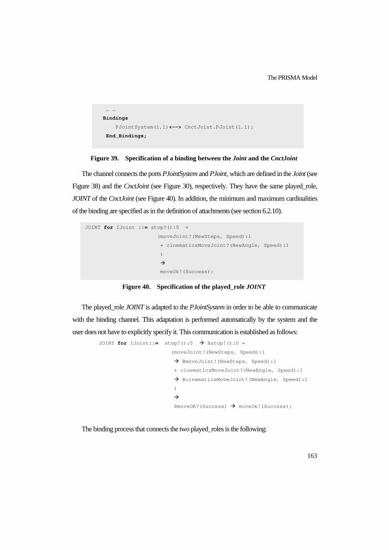
The PRISMA Model
163
Figure 39. Specification of a binding between the Joint and the CnctJoint
The channel connects the ports PJointSystem and PJoint, which are defined in the Joint (see
Figure 38) and the CnctJoint (see Figure 30), respectively. They have the same played_role,
JOINT of the CnctJoint (see Figure 40). In addition, the minimum and maximum cardinalities
of the binding are specified as in the definition of attachments (see section 6.2.10).
Figure 40. Specification of the played_role JOINT
The played_role JOINT is adapted to the PJointSystem in order to be able to communicate
with the binding channel. This adaptation is performed automatically by the system and the
user does not have to explicitly specify it. This communication is established as follows: JOINT for IJoint::= stop?():0 Bstop!():0 +
(moveJoint?(NewSteps, Speed):1
BmoveJoint!(NewSteps, Speed):1
+ cinematicsMoveJoint?(NewAngle, Speed):1
BcinematicsMoveJoint!(NewAngle, Speed):1
)
BmoveOK?(Success) moveOk!(Success);
The binding process that connects the two played_roles is the following:
… …
Bindings
PJointSystem(1,1)<--> CnctJoint.PJoint(1,1);
End_Bindings;
… …
JOINT for IJoint ::= stop?():0 +
(moveJoint?(NewSteps, Speed):1
+ cinematicsMoveJoint?(NewAngle, Speed):1
)
moveOk!(Success);

PRISMA: Aspect-Oriented Software Architectures
164
Bstop?():0 stop!():0 +
(BmoveJoint?(NewSteps, Speed):1
moveJoint!(NewSteps, Speed):1
+ BcinematicsMoveJoint?(NewAngle, Speed):1
cinematicsMoveJoint!(NewAngle, Speed):1)
moveOK?(Success) BmoveOk!(Success);
6.2.12. System PRISMA components can be simple or complex. Complex components are called systems. A
PRISMA system is a component that includes a set of connectors, simple components, and
other systems that are correctly attached to one another.
The difference between a system and a simple component is that a system is composed of a
set of architectural elements (simple components, systems, and connectors) and the attachments
and bindings that connect them.
As a component, a system captures the functionality of a software system and does not act
as a coordinator. The composition of architectural elements can lead to new aspects. These
aspects and their new weavings belong to the system. Since systems address the functionality
of software architectures in the same way as simple components, they do not have any
coordination aspects.
It is important to take into account that interfaces and played_roles that type the ports of a
system must be specified by one of the system aspects, or they must be specified by one of the
ports of the system architectural elements.
A system is specified as a pattern, so that, it can be reused in any software architecture
where necessary. This permits not only defining how its architectural elements are connected,
but also constrains the number of instances that can be created for each one of its architectural
elements. These constraints concern the minimum and maximum cardinalities, whose default
values are one and infinite, respectively.
Sometimes, the aspects of a system require services from the architectural elements of the
system and vice versa. For this reason, systems must provide a mechanism for their aspects to
communicate with their architectural elements. However, architectural elements can only
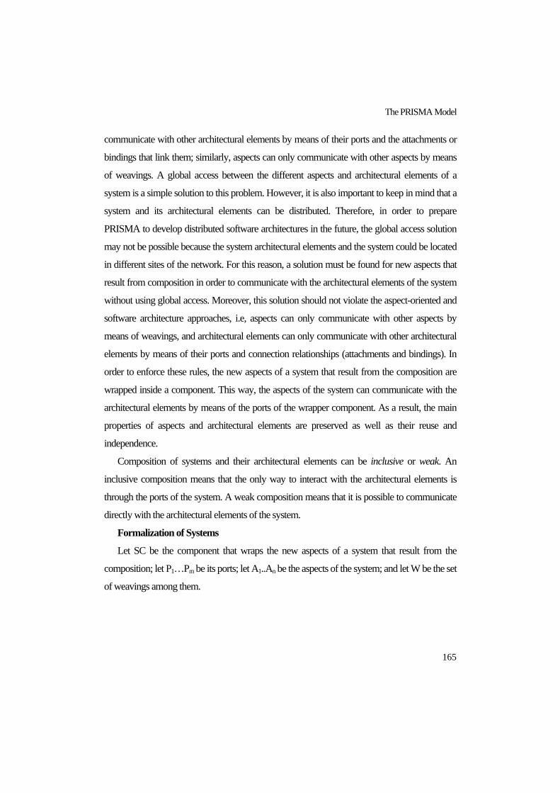
The PRISMA Model
165
communicate with other architectural elements by means of their ports and the attachments or
bindings that link them; similarly, aspects can only communicate with other aspects by means
of weavings. A global access between the different aspects and architectural elements of a
system is a simple solution to this problem. However, it is also important to keep in mind that a
system and its architectural elements can be distributed. Therefore, in order to prepare
PRISMA to develop distributed software architectures in the future, the global access solution
may not be possible because the system architectural elements and the system could be located
in different sites of the network. For this reason, a solution must be found for new aspects that
result from composition in order to communicate with the architectural elements of the system
without using global access. Moreover, this solution should not violate the aspect-oriented and
software architecture approaches, i.e, aspects can only communicate with other aspects by
means of weavings, and architectural elements can only communicate with other architectural
elements by means of their ports and connection relationships (attachments and bindings). In
order to enforce these rules, the new aspects of a system that result from the composition are
wrapped inside a component. This way, the aspects of the system can communicate with the
architectural elements by means of the ports of the wrapper component. As a result, the main
properties of aspects and architectural elements are preserved as well as their reuse and
independence.
Composition of systems and their architectural elements can be inclusive or weak. An
inclusive composition means that the only way to interact with the architectural elements is
through the ports of the system. A weak composition means that it is possible to communicate
directly with the architectural elements of the system.
Formalization of Systems
Let SC be the component that wraps the new aspects of a system that result from the
composition; let P1…Pm be its ports; let A1..An be the aspects of the system; and let W be the set
of weavings among them.

PRISMA: Aspect-Oriented Software Architectures
166
SC is defined by the tuple (A, X, Φ, Π):
A: the union of the attributes of the aspects A1…An
X: the union of the services of the aspects A1…An
Φ: the union of the formulae in modal logic of actions of the aspects A1…An
Π: the process PSC defined as follows:
PSC::= PP1 ||…|| PPm|| PA1 || …|| PAn || PW
Let S be a system, SC the component that wraps its aspects and weavings, P1..Pn its ports,
AR1..ARm the architectural elements that it contains, and ATCH1..ATCHn and BD1..BDp the
attachments and bindings that interconnect them, respectively. The semantics S is defined by
the process PS:
PS ::=PSC || PAR1 || … || PARm || PATCH1 || … || PATCHn || PBD1 || ... || PBDp
It important to keep in mind that the set of attachments ATCH1…ATCHn not only contains
the attachments among the architectural elements that the system contains, but also the
attachments between the SC and these architectural elements. In the same way, the set of
bindings BD1…BDp not only contains the bindings between the system and its architectural
elements, but also the bindings between the system and the component SC to publish the
system behaviour.
An example of system is the Joint system of the TeachMover robot (see Figure 41). This
system defines a pattern to specify architectures for joints of robots such as a base, elbow,
shoulder, etc. The system Joint imports a functional aspect to manage the position of the joint.
It defines a port to communicate with the rest of the robot parts. The system also imports the
types that are necessary to define the architectural pattern so that joints can be defined and the
number of instances can be constrained. In this case, the types are the Actuator and Sensor
components and the connector, and the default cardinality of instantiation has been applied, i.e.,
one instance as minimum and one instance as maximum. Finally, the attachments between the
imported elements and the binding are defined.

The PRISMA Model
167
Figure 41. The Joint system
6.3. CONCLUSIONS The PRISMA model has been presented in this chapter. This model allows us to describe
software architectures of complex and large systems and to improve their reusability and
maintainability. This is possible because the application of aspect-oriented software
development to software architectures provides different levels of reusability and maintenance:
the concern level (aspects) and the functional level (architectural elements).
The concern level places the properties of a concern inside an aspect. As a result, the
modification of a concern is easily found in the aspects of this concern, and the aspects of a
concern can be reused by any architectural element that needs their properties.
The functional level places functional or coordination processes of the business rules of the
software system in components and connectors, respectively. These can be easily found in
order to be reused or modified.
System Joint
Functional Aspect Import FJoint;
Ports
PJointSystem : IJoint,
Played_Role CProcessSuc.JOINT;
End_Ports
Import Architectural Elements Actuator, CnctJoint, Sensor,
WrappAspSys;
Attachments
CnctJoint.PAct(1,1)<--> Actuator.PCoord(1,1);
… …
End_Attachements;
Bindings
PJointSystem(1,1)<--> CnctJoint.PJoint(1,1);
End_Bindings;
… …
PRISMA: Aspect-Oriented Software Architectures
168
Another important property of this model is the fact that the weavings between aspects and
the relationships among architectural elements are defined outside aspects, which improves
their reusability and maintenance.
Instead of using a kernel or core entity to encapsulate functionality, aspects to define non-
functional requirements and their weavings, this model only uses aspects and weavings to
define architectural elements. The symmetrical way in which aspects are introduced in
PRISMA software architectures provides homogeneity to the model and a clean and novel way
of modelling software architectures. In PRISMA, architectural elements and aspects are used as
it they were pieces of a puzzle that fit together to form a software architecture. This way of
specifying PRISMA software architectures is presented in detail in chapter.
This chapter also has presented the formalization of the model combining the Modal Logic
of Actions and π-calculus to cope with both the structure and the behaviour of PRISMA
software architecture. This formalization defines the properties of the model and provides a
formal language that is independent of technology (see chapter 8) to specify PRISMA software
architectures and to automatically generate code from its specifications (see section 9.2).
The work related to the PRISMA model has produced a set of results that are published in
the following publications:
Jennifer Pérez, Manuel Llavador, Jose A. Carsí, Jose H. Canós, Isidro Ramos,
Coordination in Software Architectures: an Aspect-Oriented Approach, fifth Working
IEEE/IFIP Conference on Software Architecture (WICSA), IEEE Computer Society
Press, pp. 219-220, ISBN: 0-7695-2548-2, Pittsburgh, Pennsylvania, USA, 6-9 November,
2005 (position paper)
Nour H. Ali, Jennifer Pérez, Isidro Ramos, Jose A. Carsi, Aspect Reusability in Software
Architectures. The 8th International conference of Software Reuse (ICSR), July, 2004.
(poster)
Jennifer Pérez , Isidro Ramos , Javier Jaén, Patricio Letelier, Elena Navarro , PRISMA:
Towards Quality, Aspect Oriented and Dynamic Software Architectures, 3rd IEEE
International Conference on Quality Software (QSIC 2003), IEEE Computer Society
Press, pp.59-66, ISBN: 0-7695-2015-4, Dallas, Texas, USA, November 6 - 7, 2003.

The PRISMA Model
169
Jennifer Pérez , Isidro Ramos , Javier Jaén, Patricio Letelier, PRISMA: Development of
Software Architectures with an Aspect Oriented, Reflexive and Dynamic Approach,
Dagstuhl Seminar Nº 03081, Report Nº 36 "Objects, Agents and Features",Copyright (c)
IBFI gem. GmbH, Schloss Dagstuhl, D-66687 Wadern, Germany . Eds.H.-D. Ehrich
(Univ. Braunschweig, D), J.-J. Meyer (Utrecht, NL), M. Ryan (Univ. of Birmingham,
GB), pp. 16, Germany, January, 2003.
Jennifer Pérez, Nour H. Ali, Isidro Ramos, Jose A. Carsí, PRISMA: Aspect-Oriented and
Component-Based Software Architectures, Workshop on Aspect-Oriented Software
Development (DSOA), Conference on Software Engineering and Databases (JISBD),
Technical Report TR-20/2003 of the Polytechnic School of the University of
Extremadura, pp. 27-36, Alicante, November, 2003. (In Spanish)
Jennifer Pérez, Isidro Ramos, OASIS as a Formal Support for the Dynamic, Distributed
and Evolutive Hypermedia Models, Technical Report DSIC-II/22/03, pp. 144, Polytechnic
University of Valencia, October 2003. (In Spanish)
Jorge Ferrer, Ángeles Lorenzo, Isidro Ramos, José Ángel Carsí, Jennifer Pérez,
Modeling Dynamic Aspects in Architectures and Multiagent Systems, Logic Programming
and Software Engineering (CLPSE), pp. 1-13, Copenhagen, Denmark, affiliated with
ICLP, July 2002.

PRISMA: Aspect-Oriented Software Architectures
170

The PRISMA Metamodel
171
CHAPTER 7 7. THE PRISMA METAMODEL
<< There are two distinct classes of what are called thoughts:
those that we produce in ourselves by reflection and the act of thinking,
and those that bolt into the mind of their own accord.>>
Thomas Paine
Metamodels define models and establish their properties in a precise way. In addition,
metamodels facilitate the automation and maintenance of software development thanks to the
support that modeling tools currently offer for these tasks. In order to take advantage of these
properties, the PRISMA meta-level is represented by means of a metamodel that contains a set
of metaclasses that are related to each other. These metaclasses define a set of properties and
services for each concept considered in the model. The metaclasses and their relationships
define the structure and the information that is necessary to describe PRISMA architectural
models. In addition, the PRISMA metamodel defines the constraints that must be satisfied by a
PRISMA architectural model. These constraints guide the methodology for modelling
PRISMA architectural models. At the end of the modelling process, all of them must be
satisfied in order to ensure that an architectural model is correct.
The PRISMA metamodel has been specified using the class diagram of the Unified
Modelling Language (UML) 1.5. and the Object Constraint Language (OCL) 2.0 [UML06].
UML has been used to model the metaclasses and their relationships, attributes and services.
OCL has been used to specify the constraints of the metamodel. The choice of these languages

PRISMA: Aspect-Oriented Software Architectures
172
over others is based on the fact that they are standards and are widely extended languages. As a
result, they facilitate the comprehension of the model by new users.
In this chapter, each one of the packages of the PRISMA metamodel is presented in detail.
In addition to the metaclasses, relationships and constraints that packages consist of, the
attributes and services of the metaclasses are also explained. The services that are presented are
those that allow the construction of PRISMA architectural models.
7.1. THE PRISMA METAMODEL The PRISMA metamodel is composed of three main packages: Types, Architecture
Specification, and Common (see Figure 42 ).
Figure 42. Main packages of the PRISMA metamodel
Figure 43. The package Types of the PRISMA metamodel

The PRISMA Metamodel
173
The package Types contains the packages Interfaces, Aspects, Architectural Elements and
Attachments of the PRISMA model (see Figure 43). These packages define the properties of
PRISMA types.
The package Architecture Specification defines the elements that form an architectural
model using the types that are defined in the package Types. This package provides the
mechanisms to build an architectural model.
The package Common defines the utilities that are necessary to develop any kind of model.
These utilities are structured in five sub-packages: DataTypes, Parameters, Constants,
Formulae and Process. These sub-packages provide mechanisms to define data types,
parameters, constant values, formulae of different kinds and complex process, respectively (see
Figure 44).
Figure 44. The package Common of the PRISMA metamodel
7.2. THE PACKAGE “TYPES” 7.2.1. The Package “Interfaces” An interface publishes a set of services. This set of services is composed of at least one service,
and there is no limit to the number of services that can be specified (see Figure 45). The
services that make up an interface are called InterfaceServices. These services are defined in an

PRISMA: Aspect-Oriented Software Architectures
174
abstract way, without specifying whether they are going to be provided (in), requested (out), or
provided and requested (in/out) by architectural elements. An InterfaceService only specifies its
signature.
Figure 45. The package Interfaces of the PRISMA metamodel
The signature of a service specifies its name and parameters. The parameters are defined in
a specific order. The data type and kind (input/output) of parameters are also defined (see
Figure 46).
Figure 46. The package SignatureOfService of the PRISMA metamodel
The metaclass InterfaceService inherits its properties from the metaclass
ServiceDescription. This class allows the creation of services using the service newService,
whose parameter defines the name of the service that is created. The attribute name stores the
value of the ServName parameter of newService. The service addParameter adds parameters
to services (see the Parameter metaclass in Figure 76).

The PRISMA Metamodel
175
The metaclass Interface creates interfaces. The service newInterface creates a new interface,
whose parameter defines the name of the interface that is created. The service addService adds
a service to the interface, whose parameter provides the InterfaceService that is added to the
interface.
7.2.2. The package “Aspects” An aspect defines structure and behaviour of a specific concern of the software system. The
Aspects package includes all the metaclasses that are necessary to specify an aspect. The
structure and the behaviour of aspects are defined by attributes, services, preconditions,
valuations, constraints, played_roles and protocols. These concepts are sub-packages of the
Aspects package (see Figure 47).
Figure 47. The sub-packages of the package Aspects of the PRISMA metamodel
The metaclass Aspect (see Figure 48) has two attributes, name and concern. These
attributes store the name of the aspect and the concern that the aspect belongs to, respectively.
The service newAspect creates a new aspect, whose parameters define the name, the concern
and the protocol of the aspect.

PRISMA: Aspect-Oriented Software Architectures
176
Figure 48. The metaclass Aspect of the package Aspects of the PRISMA
metamodel
Aspects may need to store information to successfully perform their computation. For this
reason, the Aspect metaclass has an aggregation relationship with the Attribute metaclass . This
relationship aggregates the attributes that an aspect is composed of (see the describe
aggregation relationship in Figure 48). This aggregation is established by invoking the
addAttribute service. This service adds attributes to an aspect through its Attr parameter by
providing the attribute that is added to the aspect. Aspects may need to constrain the value of
attributes. For this reason, an aspect can be composed of constraints that determine the value of
aspect attributes (see the satisfy aggregation relationship in Figure 48).
Aspects must be composed of three or more services. The three services that are required
are the following: The services begin and end to start and finish the execution of the aspect, and
at least one service to perform the necessary computations of an aspect (see the belongsTo
aggregation relationship in Figure 48). Aspect services can be private or public. Public services
of an aspect are those that are published by an interface whose semantics is defined by the
aspect. As a result, aspects import the interfaces whose semantics they define (see the using
association relationship in Figure 47). In order to associate interfaces and services to aspects,

The PRISMA Metamodel
177
the aspect metaclass provides the addInterface and addService services, whose Inter and Serv
parameters provide the interface and the service that are added to aspects.
In order to define the semantics of aspect services, aspects are composed of preconditions,
valuations, played_roles and a protocol (see the aggregation relationships condition, include,
play and executes in Figure 48). For this reason, the Aspect metaclass has three services to
associate preconditions, valuations, and played_roles to aspects. These services are
addPrecondition, addValuation, and addPlayedRole, respectively.
In addition to these attributes, services, and relationships, the metaclass Aspect has an
associated set of constraints to completely model its properties (see Figure 49).
Figure 49. Constraints of the metaclass Aspect
These constraints correspond to the OCL rules shown in Figure 49. They specify the
following:
<<Every aspect has a “begin” service>>
<<Every aspect service must participate in the protocol of the aspect>>
<<Every aspect has an “end” service>>

PRISMA: Aspect-Oriented Software Architectures
178
<<For each interface that an aspect imports, the aspect must define at least a played_role
associated to this interface>>
<<Every service of an interface that is imported by an aspect must be a service of the
aspect>>
7.2.2.1. The package “Attributes” Attributes store a value of a specific data type. Therefore, each aspect attribute must be
associated to a data type (see Figure 50).
Figure 50. The package Attributes of the PRISMA metamodel
The metaclass Attribute has two attributes, name and default. The attribute name stores the
name of the aspect and the attribute default stores the default value of the attribute when
necessary. The service newAttribute creates a new attribute, whose parameters define the name
and the default value of the attribute.
In PRISMA, it is possible to define different kinds of attributes. The semantics of each kind
is defined in the kindsofAttributes sub-package of the Attributes package. Attributes can be
classified into derived and non-derived attributes (see Figure 51). Derived attributes calculate
their values on demand by applying a derivation rule. The derivation rule is associated to the
derived attribute (see Figure 52). Non-derived attributes store their values, and it is possible to
constrain the fact that they must contain a value by means of the notNull attribute (see the
NonDerivedAttribute metaclass in Figure 51). If notNull is true, the attributes must contain a
value; if notNull is false, no value is required. In order to correctly define the semantics of non-

The PRISMA Metamodel
179
derived attributes, there are two constraints associated to the NonDerivedAttribute metaclass.
These constraints correspond to the OCL rules shown in Figure 51. They specify the following:
<<For each non-derived attribute that cannot contain a null value, there is a postcondition
of the begin service valuation that must provide a value to the attribute >>
<<The ”notNull” attribute of a constant attribute is always true>>
Figure 51. The package KindsOfAttributes of the PRISMA metamodel
Non-derived attributes can be constant or variable. Constant attributes store values that
cannot change; i.e., they cannot be modified during the execution of the aspect. Also, variable
attributes store values that can be modified during the execution of the aspect.
Figure 52. The package Derivations of the PRISMA metamodel

PRISMA: Aspect-Oriented Software Architectures
180
7.2.2.2. The package “Services” The metaclass Service is a specialization of the metaclass InterfaceService (see Figure 53). As a
result, it inherits all its properties and services. The metaclass Service defines that every service
of an aspect must be characterized by the behaviour that it offers in the context of the aspect.
This means that the service can either be provided, requested or both by the aspect. This
characteristic is specified by the type attribute of the metaclass. The type values are in, out and
in/out to define the behaviour of a server (provide), a client (request), or both a server and a
client (provide and request), respectively. A service of an aspect can also have an alias. An alias
permits changing the name of an InterfaceService inside the aspect. This metaclass stores the
alias name and provides the newAlias service to change the name. The parameters of newAlias
are the service whose name is going to be changed and the new alias.
Figure 53. The package Services of the PRISMA metamodel
There are two kinds of services: simple services and transactions (see Figure 54). A
transaction is a complex service that it is composed of more than one service and is executed in
a transactional way (all or nothing) (see the composedService aggregation in Figure 54). A

The PRISMA Metamodel
181
transaction describes a process, which models how and when the different services that
compose the transaction are executed. As a result, a transaction is a specialization of the
Process metaclass (see Figure 80).
Figure 54. The package KindsOfServices of the PRISMA metamodel
7.2.2.3. The package “Constraints” Constraints are formulae that establish conditions on the state of the aspect that they belong to.
As a result, each time that a service execution is finished, the value of each attribute must
satisfy the aspect constraints. As explained in (see section 6.2.4), there are two kinds of
constraints: static and dynamic (see Figure 55).
Figure 55. The package Constraints of the PRISMA metamodel
The metaclass Constraint is an abstract class that has only one attribute, the name of the
constraint. This metaclass is specialized into two metaclasses: StaticConstraint and

PRISMA: Aspect-Oriented Software Architectures
182
DynamicConstraint. Each one of them provides a constructor service to create instances of
static and dynamic constraints, respectively. The service newStaticConstraint creates a new
static constraint giving the name and the condition of the constraint as parameters. The service
newDynamicConstraint creates a new dynamic constraint, whose parameters define the name
of the constraint and a condition that uses a temporal operator (see the Formulae package in
Figure 78).
7.2.2.4. The package “Preconditions” Preconditions establish the condition that must be satisfied to execute an aspect service.
Therefore, the metaclass Precondition has the aggregation relationship establishCondition and
aggregation relationship constrains with the metaclasses Condition and Service, respectively
(see Figure 56). The first aggregation establishes that a precondition must define the service that
it affects. The second aggregation establishes the condition that must be satisfied to execute the
service.
Figure 56. The package Preconditions of the PRISMA metamodel
The metaclass Precondition only has one attribute, the name of the precondition. The
service newPrecondition creates a new precondition, whose parameters define the name, the
condition that must be satisfied, and the service that will only be executed if the condition is
satisfied. In addition, the metaclass Precondition has an associated constraint in order to ensure
that the aspect execution is not conditioned by a precondition. This constraint corresponds to
the OCL rule shown in Figure 56. It specifies the following:

The PRISMA Metamodel
183
<<A service begin does not have preconditions associated to it since the start of the aspect
execution cannot be conditioned by the aspect itself>>
This constraint is necessary because preconditions are used to define the business logic of
the software system and not to define the mechanisms of creating, destroying or executing
instances.
7.2.2.5. The package “Valuations” Valuations establish how the service executions affect the aspect state. This semantics is
specified by means of two conditions: one that must be satisfied before the service execution
and another that must be satisfied after the service execution. For this reason, the metaclass
Valuation has three aggregation relationships with the metaclasses Condition, Service and
Postcondition (see Figure 57).
Figure 57. The package Valuations of the PRISMA metamodel
The metaclass Condition defines the condition that specifies the state of the aspect before
the service execution. This condition is optional, this means it does not have to be specified
when the state before the execution is not relevant to the state change (see the conditioned
aggregation in Figure 57). However, the specification of the condition after the service
execution is mandatory. The postcondition must be satisfied after the service execution. Since
the metaclass Postcondition defines the change in one attribute or parameter and a valuation
can affect several attributes or parameters, a valuation can have more than one postcondition
associated to it in order to model the service changes in several attributes and/or parameters (see
the evaluate aggregation in Figure 57).

PRISMA: Aspect-Oriented Software Architectures
184
The metaclass Valuation has only one attribute, the name of the valuation. The service
newValuation creates a new valuation, whose parameters define the name, the service that
produces the change of state, and the condition that must be satisfied after the service execution.
Moreover, it has two services addCondition and addPostCondition. The addCondition adds a
condition to the valuation. This condition must be satisfied before the service execution. The
addPostCondition adds more that one postcondition when the valuation affects several
attributes or parameters.
7.2.2.6. The package “PlayedRoles” PlayedRoles establish how the services of an interface can be executed. As a result, a
played_role defines a process that orchestrates the service execution of a specific interface.
Since the metaclass Played_Role defines a process, it inherits the properties of the metaclass
Process (see the Processes package in Figure 80).
Figure 58. The package PlayedRoles of the PRISMA metamodel
The metaclass Played_Role has two association relationships with the metaclasses Interface
and Service (see Figure 58). A played_role defines the behaviour of only one interface (see the

The PRISMA Metamodel
185
the for association in Figure 58) and describes the execution process of more than one service
(see the order association in Figure 58). However, the played_role cannot be related to any
interface or service of the software system. As a result, these relationships are constrained by
three constraints. These constraints correspond to the OCL rules shown in Figure 58. They
specify the following:
<<Every interface that an aspect imports must have associated a played_role>>
<<The interface of a played_role is one of the interfaces that imports the aspect that the
played_role belongs to>>
<<Every service that participate in a played_role must be a service of the played_role
interface>>
The metaclass Played_Role has one attribute, the name of the played_role. The service
newPlayedRole creates a new played_role, whose parameters define the name and the
interface. The behaviour of this interface is defined by the played_role.
7.2.2.7. The package “Protocols” A protocol establishes how the services of an aspect can be executed. As a result, a protocol
defines a process that coordinates the private and public services of an aspect. Since the
metaclass Protocol defines a process, it inherits the properties of the metaclass Process (see the
Processes package in Figure 80).
Figure 59. The package Protocols of the PRISMA metamodel
PRISMA: Aspect-Oriented Software Architectures
186
A service can be private or public and only belongs to one aspect. For this reason, a service
can only participate in one protocol: the protocol of the aspect that it belongs to (see the
privateandpublicsynch association Figure 59). In addition, each service of the aspect must
participate in its protocol (see the constraint in the Aspect package in Figure 49).These services
can be either private or public services, but there must be at least three: the begin and end
services of an aspect, and one service to perform the computation of the aspect (see the
privateandpublicsynch association in Figure 59).
A protocol is the glue of the played_roles and the private services of the aspect. As a result,
the protocol coordinates the many different played_roles that have been defined in the aspect
that it belongs to. However, a played_role is only coordinated one protocol, its aspect protocol
(see the coordinates association in Figure 59). Played_roles are specified using the public
services of an aspect. Since aspect services can be private or public, those that are private are
not related to played_roles (see the order association in Figure 59).
The metaclass Protocol has one attribute, the name of the protocol. The service
newProtocol creates a new protocol by providing the name of the protocol as a parameter.
7.2.3. The package “ArchitecturalElements” In PRISMA, there are three kinds of architectural elements: components, connectors, and
systems (see Figure 60). The package ArchitecturalElements defines the metaclass
ArchitecturalElement. It is an abstract metaclass that specifies the commonalities of the three
kinds of PRISMA architectural elements. In addition, it includes all subpackages that define the
concepts required to specify PRISMA architectural elements.
The metaclass ArchitecturalElement has two aggregation relationships with the
metaclassess Port and Weaving, and one association relationship with the metaclass Aspect (see
Figure 61). An architectural element has at least one port; the port is part of the architectural
element and does not have its own entity without the architectural element. In other words, the
aggregation between the port and the architectural element is inclusive (see the has aggregation
in Figure 61). An architectural element imports at least one aspect and an aspect can be
imported by one or more architectural elements of the software system (see the imports

The PRISMA Metamodel
187
association in Figure 61). In addition, an architectural element can include a set of weavings to
synchronize its aspects. These Weavings are related to the architectural element by means of an
inclusive aggregation (see the weaves aggregation in Figure 61).
Figure 60. The subpackages of the package ArchitecturalElements of the PRISMA metamodel
The metaclass ArchitecturalElement has one attribute, the name of the architectural
element. In addition, it has three services addAspect, addPort, addWeaving to associate aspects,
ports, and weavings to the architectural element, respectively (see Figure 61). It is important to
emphasize that this metaclass does not have a constructor (new service) because it is an abstract
class that cannot be instantiated.
The metaclass ArchitecturalElement has two constraints associated to it in order to
completely define its properties. These constraints correspond to the OCL rules shown in
Figure 61. They specify the following:
<<There are no two ports of an architectural model that have the same interface and the
same played_role associated >>
<<An architectural element cannot import more than one aspect of the same concern>>

PRISMA: Aspect-Oriented Software Architectures
188
Figure 61. The package ArchitecturalElements of the PRISMA metamodel
The package KindsOfArchitecturalElements is a subpackage of the package
ArchitecturalElements, and it classifies architectural elements into components and connectors.
As a result, this package specifies that components and connectors inherit the properties of the
ArchitecturalElement metaclass, and it also contains the packages that define components and
connectors.
Figure 62. The package KindsOfArchitecturalElements of the PRISMA
metamodel

The PRISMA Metamodel
189
7.2.4. The package “Weaver” The package Weaver defines the weavings of architectural elements. It contains the metaclass
weaving which is formed by two aspect services. One of the services, the pointcut service,
triggers the execution of the weaving; the other service, the advice service, is executed as a
consequence of the weaving. The relationships between the weaving and these two services are
modelled in the metamodel by means of two aggregations (see Figure 63). In addition, if the
weaving is conditional, it has a condition associated to it.
There are certain constraints that must be satisfied in order to associate the appropriate
services to a weaving definition. As a result, the metaclass Weaving has constraints associated
to it. These constraints correspond to the OCL rules shown in Figure 64. They specify the
following:
<<The services that participate in the weaving must belong to aspects that are imported by
the architectural element in which the weaving is defined>>
<<If the weaving uses a conditional operator, it must have a condition associated to it.
However, if the weaving does not use a conditional operator, it cannot have a condition
associated to it>>
<<The services that participate in a weaving must belong to different aspects>>
<<The aspects of the services that participate in a weaving must define different
concerns>>
Figure 63. The package Weaver of the PRISMA metamodel
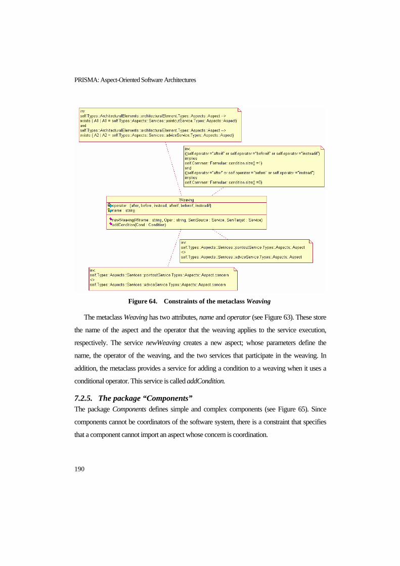
PRISMA: Aspect-Oriented Software Architectures
190
Figure 64. Constraints of the metaclass Weaving
The metaclass Weaving has two attributes, name and operator (see Figure 63). These store
the name of the aspect and the operator that the weaving applies to the service execution,
respectively. The service newWeaving creates a new aspect; whose parameters define the
name, the operator of the weaving, and the two services that participate in the weaving. In
addition, the metaclass provides a service for adding a condition to a weaving when it uses a
conditional operator. This service is called addCondition.
7.2.5. The package “Components” The package Components defines simple and complex components (see Figure 65). Since
components cannot be coordinators of the software system, there is a constraint that specifies
that a component cannot import an aspect whose concern is coordination.

The PRISMA Metamodel
191
The metaclass Component provides a service to create components. This service is called
newComponent, and its parameter is the name of the component that is created as a result of the
service execution.
Figure 65. The package Components of the PRISMA metamodel
Since systems are complex components, they inherit all the properties of components. For
this reason, the package that defines a system is a subpackage of the Component metaclass.
7.2.6. The package “Connectors” The package Connectors defines the connector architectural element (see Figure 66). Since
connectors act as coordinators of components, the metaclass Connector has an associated
constraint that specifies that a connector must import an aspect whose concern is coordination
(see the first constraint that appears in Figure 66).
Figure 66. The package Connectors of the PRISMA metamodel

PRISMA: Aspect-Oriented Software Architectures
192
Morevover, the metaclass Connector has another constraint associated to it that specifies
the following:
<<A connector must have at least two attachments associated to it, and each attachment
must connect the connector to two different components>>
The metaclass Connector provides a service to create connectors. This service is called
newConnector, and its parameter is the name of the connector that is created as a result of the
service execution
7.2.7. The package “Attachments” Attachments define types of communication channels between the ports of a component and
the port of a connector. As a result, the metaclass Attachment is related to the metaclass Port by
means of an association relationship (see Figure 73). This relationship establishes that the
attachment must be related to two ports. However, it is necessary to constrain this association
with a constraint in order to establish that one of the ports must belong to a component and that
the other one must belong to a connector.
Figure 67. The package Attachments of the PRISMA metamodel
Figure 68. The attachment between the Joint and the CnctMUC of the
TeachMover

The PRISMA Metamodel
193
card_max_port_component = 1
card_max_port_connector = 1
card_max_port_component = 1
card_max_port_connector = n
card_max_port_component = n
card_max_port_connector = 1
card_max_port_component = n
card_max_port_connector = n
Figure 69. Different configuration of an architecture depending on the
maximum cardinality of an attachment
In addition to the attachment name for storing the name of the attachment, the metaclass
Attachment has four more attributes to specify the attachment communication pattern, i.e., the
instantiation pattern of the attachment. It is necessary to constrain how many instances of the
attachment can be attached to the port of the component instance and the port of the connector
instance. The attribute card_min_port_component specifies the minimum number of
attachment instances that must be connected to one instance of this component through the

PRISMA: Aspect-Oriented Software Architectures
194
port. The attribute card_max_port_component specifies the maximum number of attachment
instances that must be connected to one instance of this component through the port. The
attribute card_min_port_connector specifies the minimum number of attachment instances that
must be connected to one instance of this connector through the port. The attribute
card_max_port_connector specifies the maximum number of attachment instances that must
be connected to one instance of this connector through the port. Figure 69 shows an example
of how the maximum cardinality of the attachment can vary the configuration of the
architecture at the instance level. The attachment defined between the Joint system and the
CnctMUC connector of the TeachMover architecture is used to exemplify this variation (see
Figure 35).
Moreover, the metaclass Attachment has the service newAttachment to create a new
attachment. Its parameters are the name of the attachment that is created as a result of the
service execution, the component port and the connector port that it connects, and the
minimum and maximum cardinalities for each one of the ports.
7.2.8. The package “Systems” The package Systems defines complex components (see Figure 70). Systems are complex
components that are composed of a set of architectural elements and their attachments. For this
reason, the metaclass System has an aggregation with each one of the metaclasses Component,
Connector and Attachment.
The architectural elements that compose a system can be directly related to other elements
or their access can only be possible through the system. These two kinds of composition are
referential and inclusive, respectively. The analyst can model any of these compositions for the
architectural elements of the system, depending on the requirements of the system. However,
the definition of an inclusive composition between a system and an architectural element
requires the definition of a channel between a system port and a port of the architectural
element. This channel is required to resend the provided and requested services of the
architectural element through the system port. These channels are called bindings. Therefore,

The PRISMA Metamodel
195
the metaclass System has an aggregation relationship with the metaclass Binding. Bindings are
defined in the Bindings subpackage of the System package.
Figure 70. The package Systems of the PRISMA metamodel
The metaclass System must be related to at least one component in order to be complex (see
the containsComp aggregation in Figure 70). In addition, it has an associated constraint that
ensures a correct composition. It specifies the following:
<<If a system does not import any aspect, the system must have at least one binding
associated to it >>
The metaclass System has four services. The service newSystem creates a new system by
providing the name of the system as a parameter. In addition, the services addComponent,
addConnector, addAttachment and addBinding add components, connectors, attachments and
bindings, respectively, to the system.
7.2.9. The package “Bindings” The metaclass Binding is related to the metaclass Port by means of two association
relationships (see Figure 73). These associations establish that the binding must be related to a
system port and an architectural element port. However, the architectural element that the port
belongs to must be one of the architectural elements of the system. This constraint is applied

PRISMA: Aspect-Oriented Software Architectures
196
not only at the types level, but also at the configuration level (instances). For this reason, the
metaclass Binding has an associated constraint that specifies this requirement.
In addition to the attribute name for storing the name of the binding, the metaclass Binding
has four more attributes to specify the communication pattern of the binding. As a result, the
attribute card_min_port_AR specifies the minimum number of binding instances that must be
connected to one instance of this architectural element through the port. The attribute
card_max_port_AR specifies the maximum number of binding instances that must be
connected to one instance of this architectural element through the port. The attribute
card_min_port_Sys specifies the minimum number of binding instances that must be
connected to one instance of this system through the port. The attribute card_max_port_Syst
specifies the maximum number of binding instances that must be connected to one instance of
this system through the port.
Figure 71. The package Bindings of the PRISMA metamodel

The PRISMA Metamodel
197
Moreover, the metaclass Binding has the service newBinding to create a new binding. Its
parameters are the name of the binding that is created as a result of the service execution, the
system port and architectural element port that it connects, and the minimum and maximum
cardinalities for each one of the ports.
7.2.10. The package “Ports” Ports publish the services of an interface and constrain how these services can be provided or
requested by means of a played_role. For this reason, the metaclass Port has two aggregation
relationships with the metaclasses Interface and Played_Role (see Figure 72).
Figure 72. The package Ports of the PRISMA metamodel
However, ports cannot be related to any interface or played_role of the software system. As
a result, these relationships are constrained by the following two constraints that correspond to
the two that appear in Figure 73:
<<If the architectural element that the port belongs to is not a system, the played_role of
the port must be defined for one of the aspects that the architectural element imports. In
addition, the interface of the played_role must be the same one as the interface of the port>>
<<If the architectural element that the port belongs to is a system, there are two possible
options: 1) either the played_role of the port is defined for one of the aspects that the system
imports, and the interface of the played_role is the same as the interface of the port; 2) or the
port has the same interface and played_role as one port of the architectural element of the
system>>

PRISMA: Aspect-Oriented Software Architectures
198
Figure 73. Constraints of the metaclass Port
The metaclass Port has one attribute, the name of the port. The service newPort creates a
new port by providing the name of the port, the interface and the played_role as parameters.
7.3. THE PACKAGE “ARCHITECTURE SPECIFICATION” The package Architecture Specification defines how a PRISMA architecture can be defined
using the types defined in the package Types. The metaclass PRISMAArchitecture has five
aggregation relationships with each one of the first-order citizens of the PRISMA model. They
are components, connectors, aspects, interfaces, and attachments. Since components,
connectors, interfaces, and aspects are reusable, they can be used by more than one
architectural element (see Figure 74).

The PRISMA Metamodel
199
Figure 74. The package Architecture Specification of the PRISMA
metamodel
The metaclass PRISMAArchitecture has one attribute, the name of the architectural model.
The service newArchitecture creates a new architectural model by providing its name as a
parameter. In addition, the metaclass provides five services to add attachments, components,
connectors, interfaces and aspects to the architectural model. In order to ensure that a model is
correctly defined, the metaclass PRISMAArchitecture has a set of constraints associated to it
(see Figure 74). Their meaning is the following:
<<An architectural model must include every aspect that is imported by its components
and/or connectors>>
<<An architectural model must include every interface that is used by its aspects >>

PRISMA: Aspect-Oriented Software Architectures
200
7.4. THE PACKAGE “COMMON” The package Common defines the utilities that are necessary to develop any kind of model.
These utilities consist of providing mechanisms to define data types, parameters, constant
values, different kinds of formulae and complex processes. Since these are utilities that are
common to all models, they are not going to be explained in detail in this thesis. However, the
different packages that the Common package is composed of are shown in the figures that are
presented in this section in order to provide the complete specification of the PRISMA
metamodel.
Figure 75. The package DataTypes of the PRISMA metamodel
Figure 76. The package Parameters of the PRISMA metamodel
Figure 77. The package Constants of the PRISMA metamodel

The PRISMA Metamodel
201
Figure 78. The package Formulae of the PRISMA metamodel
Figure 79. The constraint of the metaclass Postcondition of the Package Formulae

PRISMA: Aspect-Oriented Software Architectures
202
Figure 80. The package Processes of the PRISMA metamodel
Figure 81. Constraints of the metaclass Transition of the package Processes

The PRISMA Metamodel
203
7.5. CONCLUSIONS The PRISMA metamodel has been presented in this chapter. This metamodel permits the
creation of PRISMA architectural models in a correct way and the accurate definition of their
properties. In addtition, it facilitates the integration of the PRISMA model into modelling tools
that support the incorporation of new metamodels.
The PRISMA metamodel defines the required metaclasses, their properties and services,
and their relationships with each other. In addition, the metamodel specifies the constraints to
ensure that the definition of an architectural model is correct.
In the thesis, only the services for creating architectural models are presented. Each
metaclass provides a set of services to create the concept that it defines, as well as a set of
services to relate the concept to other concepts. It is assumed that each one of the metaclasses
has the necessary services to destroy and delete architectural models in a consistent way.
The metamodel is the repository structure that stores PRISMA architectural models,
preserving the reusability of interfaces, architectural elements and aspects. In addition, the
metamodel introduces a methodology to follow when a PRISMA architectural model is
specified by means of constraints.
The PRISMA metamodel has been defined to be able to support evolution at run-time in
the future. This evolution could be supported at different levels of granularity by adding the
evolution services to the different metaclasses of the metamodel. This would consist of adding
or removing architectural elements of the model, or adding or removing properties of an aspect
(attributes, services, etc). In addition to adding evolution services to the metamodel, a
mechanism to invoke these services at run-time should be provided to support run-time
evolution.
The PRISMA metamodel with its properties of creation, destruction and evolution has been
published in the following publications:
Jennifer Pérez, Nour Ali, Jose A. Carsí, Isidro Ramos, Dynamic Evolution in Aspect-
Oriented Architectural Models, Second European Workshop on Software Architecture,
Springer LNCS 3527, pp.59-16, ISSN: 0302-9743, ISBN: 3-540-26275-X , Pisa, Italy,
June 2005.

PRISMA: Aspect-Oriented Software Architectures
204
Jennifer Pérez, Isidro Ramos, Jose A. Carsí, A Compiler to Automatically Generate the
Metalevel of Specifications using Properties of the Base Level, Technical Report, DSIC-
II/23/03, pp. 107, Polytechnic University of Valencia, October, 2003.(In Spanish)

The PRISMA Aspect-Oriented Architecture Description Language
205
CHAPTER 8 8. THE PRISMA ASPECT-ORIENTED
ARCHITECTURE DESCRIPTION LANGUAGE
<< Language is the dress of thought>>
Samuel Johnson
The PRISMA approach provides an Architecture Description Language (ADL) to specify
software architectures following the PRISMA model. Since the PRISMA model combines
AOSD with software architectures, its language is an Aspect-Oriented Architecture Description
Language (AOADL).
The PRISMA AOADL provides the syntactical constructions that allow the description of
PRISMA architectural models. It is based on a Modal Logic of Actions [Sti92] and the dialect
of polyadic π-calculus [Mil93] that is presented in section 5.2. In addition, some of the
syntactical constructions of the language and the Modal Logic of Actions that is used come
from the OASIS language [Let98]. OASIS is a formal language that defines conceptual models
of information systems. As a result, the PRISMA AOADL defines the semantics of the
architectural models in a formal way.
The PRISMA AOADL defines the architectural elements at different levels of abstraction:
the type definition level and the configuration level. The type definition level defines
architectural types with a high abstraction level in order to be reused by other types or specific
architectures.
PRISMA: Aspect-Oriented Software Architectures
206
The configuration level designs the architecture of software systems by creating and
interconnecting instances of the defined architectural elements in the type definition level. In
other words, it specifies the topology of a specific architectural model.
The purpose of this chapter is to present the structure and syntax of the PRISMA AOADL
in detail. In this chapter, only the most important structures are presented. The complete BNF
of the PRISMA AOADL and its notation is presented in detail in appendix A
8.1. THE TYPE DEFINITION LEVEL The type definition level of PRISMA defines architectural patterns (complex components) and
the first-class citizens of the language: interfaces, aspects, components, and connectors.
8.1.1. Interface An interface describes the signature of the services that can be provided or requested through
that interface. The specification of the interface consists of specifying its name and the list of
services that it publishes between the reserved words Interface and End_Interface. Services are
specified by defining their signature. The signature of a service specifies its name and
parameters. The data type and the kind (input/output) of parameters are also declared. The
template for specifying an interface is presented in Figure 82.
With regard to the nomenclature of concepts, it is recommended to follow an agreement
during the specification. PRISMA proposes that the names of interfaces start with the letter I in
uppercase. It is also recommended that the first letter of parameters be written with a capital
letter and the first letter of services be written with a small letter.
An example of an interface in the TeachMover robot is the IMotionJoint interface, which
publishes the moveJoint and stop services (see Figure 83). The moveJoint service has two input
parameters whose names are NewSteps and Speed. Both parameters store values of the integer
data type and are input parameters. Input parameters are those that provide information for the
service execution; whereas output parameters are those that provide the result of the execution
of the service. In addition, it is possible to declare services without parameters; an example is
the stop service that the IMotionJoint also publishes.

The PRISMA Aspect-Oriented Architecture Description Language
207
Figure 82. Specification template of interfaces
Figure 83. Specification of the interface IMotionJoint
8.1.2. Aspects An aspect defines the structure and the behaviour of a specific concern of the software system.
A common syntax of aspects has been defined independently of the concern that they define.
The template for specifying an aspect is composed of several sections (see Figure 84).
The aspect specification is delimited by the reserved words Aspect and End_Aspect. The
head of an aspect specifies its name and the kind of concern it defines: functional, coordination,
safety, etc. Moreover, interfaces whose semantics are defined by aspects are detailed next to the
reserved word using.
Figure 85 shows the head of the aspect CProcessSuc of the TeachMover software
architecture. Since the aspect specifies coordination rules, the concern of the aspect is
Coordination. This aspect uses four interfaces: IMotionJoint, IRead, IJoint, and IPosition. As a
result, they are specified in the head of the aspect definition.
<interface> ::= Interface <interface_name>
<iservice_list>
End_ Interface <interface_name> ;
<iservice> ::= <service_name> ‘(‘ [<param_service_list>] ’)’ ‘;’
<param_service> ::= <parameter_type> <parameter>
<parameter_type> ::= input | output
<parameter> ::= <parameter_name> ‘:’ <data_type>
Interface IMotionJoint
moveJoint (input NewSteps: integer, input Speed: integer);
stop();
End_Interface IMotionJoint;

PRISMA: Aspect-Oriented Software Architectures
208
Figure 84. Specification template of aspects
Figure 85. Specification of an aspect head with interfaces (CProcessSuc)
However, it is also possible to define an aspect without using any interface. This is the case
of the SMotion aspect of the TeachMover software system (see Figure 86).
Figure 86. Specification of an aspect head without interfaces (SMotion)
The sections that the aspect is composed of are explained in the following subsections.
Safety Aspect SMotion
… …
End_Aspect SMotion;
Coordination Aspect CProcessSuc using IMotionJoint, IRead, IJoint,
IPosition
… …
End_Aspect CProcessSuc;
<aspect> ::= <concern> Aspect <aspect_name> [using <interface_name_list>]
[ <constant_attributes> ]
[ <variable_attributes> ]
[ <derived_attributes> ]
<services>
[ <preconditions> ]
[ <transactions> ]
[ <constraints> ]
[<played_roles>]
<protocol>
End_Aspect <aspect_name>‘;’
<concern> ::= functional | coordination | safety | integration | distribution |
replication | mobility | quality | persistence | presentation |
navigational | context-awareness

The PRISMA Aspect-Oriented Architecture Description Language
209
8.1.2.1. Attributes Attributes are specified inside an aspect. They are necessary to store information about the
characteristics of the aspect. Attributes are preceded by the reserved word Attributes and they
have a name and a data type. The data type defines the kind of values that the attribute can
store. There are three kinds of attributes:
Constant: The stored values cannot change
Variable: The stored values can be changed
Derived: The value is calculated on demand applying its derivation rule.
The template for specifying these three kinds of attributes is presented in Figure 87. In the
aspect specification, the different kinds of attributes are denoted by the reserved words
Constant, Variable, or Derived.
Variable and constant attributes can store a value by default, which can only be modified
when the attribute is variable. In addition, variable attributes can specify that they must always
store a value by specifying the reserved word NOT NULL after their data type specification.
Figure 87. Specification template of attributes
Derived attributes must specify the derivation formula that describes how to calculate their
value. This formula can be a condition, an arithmetic expression, or a function that has been
defined by the user.
<constant_attributes> ::= Constant < cons_attribute_seq>
<variable_attributes> ::= Variable <var_ attribute_seq>
<derived_attributes> ::= Derived <der_attribute_seq>
< cons_attribute> ::= <attribute_name>‘:’ <data_type> [, DEFAULT:] <value>
<var _attribute> ::= <attribute_name>‘:’ <data_type>[‘,’ NOT NULL ]
[, DEFAULT:] <value>
<der_attribute> ::= <attribute_name>‘:’ <data_type>‘,’ derivation‘:’ <formulae>
<formulae> ::= <condition> | <arithmetic_expression> | <function>

PRISMA: Aspect-Oriented Software Architectures
210
With regard to the nomenclature of concepts, PRISMA proposes that the first letter of an
attribute be written in small letters to clearly distinguish attributes from parameters, which start
with capital letters.
An example of the specification of constant attributes is the specification of the attributes of
the SMotion aspect (see Figure 88). This aspect specifies the minimum, maximum attributes,
whose data type is integer and they must store a value.
Figure 88. Specification of the constant attributes of the aspect SMotion
Figure 89. Specification of the variable and derived attributes of the aspect
FJoint
Another example is the specification of the attributes of the FJoint aspect, which shows
how to specify variable and derived attributes (see Figure 89). It specifies one variable attribute,
halfSteps. Its data type is integer and is constrained by the NOT NULL property. Therefore, it
cannot be empty.
In addition, the aspect specifies the derived attribute angle. In this case, the attribute is
calculated using a function defined by the user. The function FtransHalfStepsToAngle
Safety Aspect SMotion
Attributes
Constant
minimum, maximum: integer;
… …
End_Aspect SMotion;
Functional Aspect FJoint using IPosition
Attributes
Variable
halfSteps : integer, NOT NULL;
Derived
angle: integer, derivation:
FtransHalfStepsToAngle(halfSteps);
… …
End_Aspect FJoint;
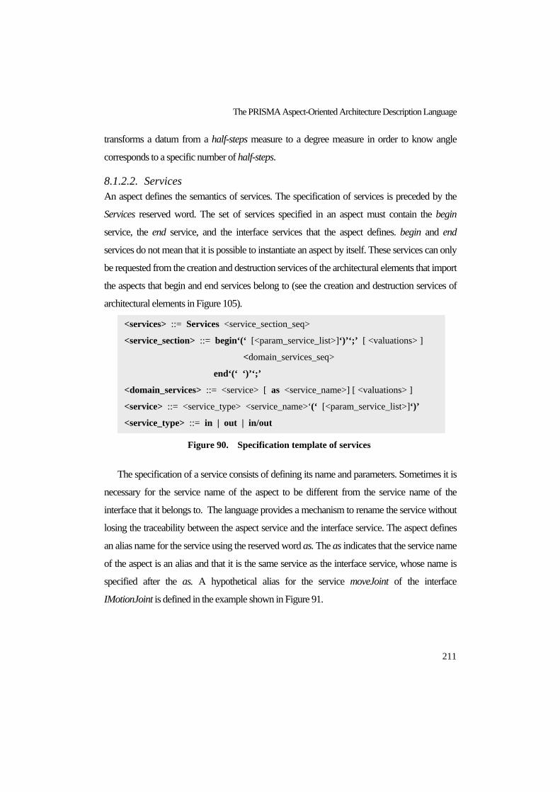
The PRISMA Aspect-Oriented Architecture Description Language
211
transforms a datum from a half-steps measure to a degree measure in order to know angle
corresponds to a specific number of half-steps.
8.1.2.2. Services An aspect defines the semantics of services. The specification of services is preceded by the
Services reserved word. The set of services specified in an aspect must contain the begin
service, the end service, and the interface services that the aspect defines. begin and end
services do not mean that it is possible to instantiate an aspect by itself. These services can only
be requested from the creation and destruction services of the architectural elements that import
the aspects that begin and end services belong to (see the creation and destruction services of
architectural elements in Figure 105).
Figure 90. Specification template of services
The specification of a service consists of defining its name and parameters. Sometimes it is
necessary for the service name of the aspect to be different from the service name of the
interface that it belongs to. The language provides a mechanism to rename the service without
losing the traceability between the aspect service and the interface service. The aspect defines
an alias name for the service using the reserved word as. The as indicates that the service name
of the aspect is an alias and that it is the same service as the interface service, whose name is
specified after the as. A hypothetical alias for the service moveJoint of the interface
IMotionJoint is defined in the example shown in Figure 91.
<services> ::= Services <service_section_seq>
<service_section> ::= begin‘(‘ [<param_service_list>]‘)’‘;’ [ <valuations> ]
<domain_services_seq>
end‘(‘ ‘)’‘;’
<domain_services> ::= <service> [ as <service_name>] [ <valuations> ]
<service> ::= <service_type> <service_name>‘(‘ [<param_service_list>]‘)’
<service_type> ::= in | out | in/out
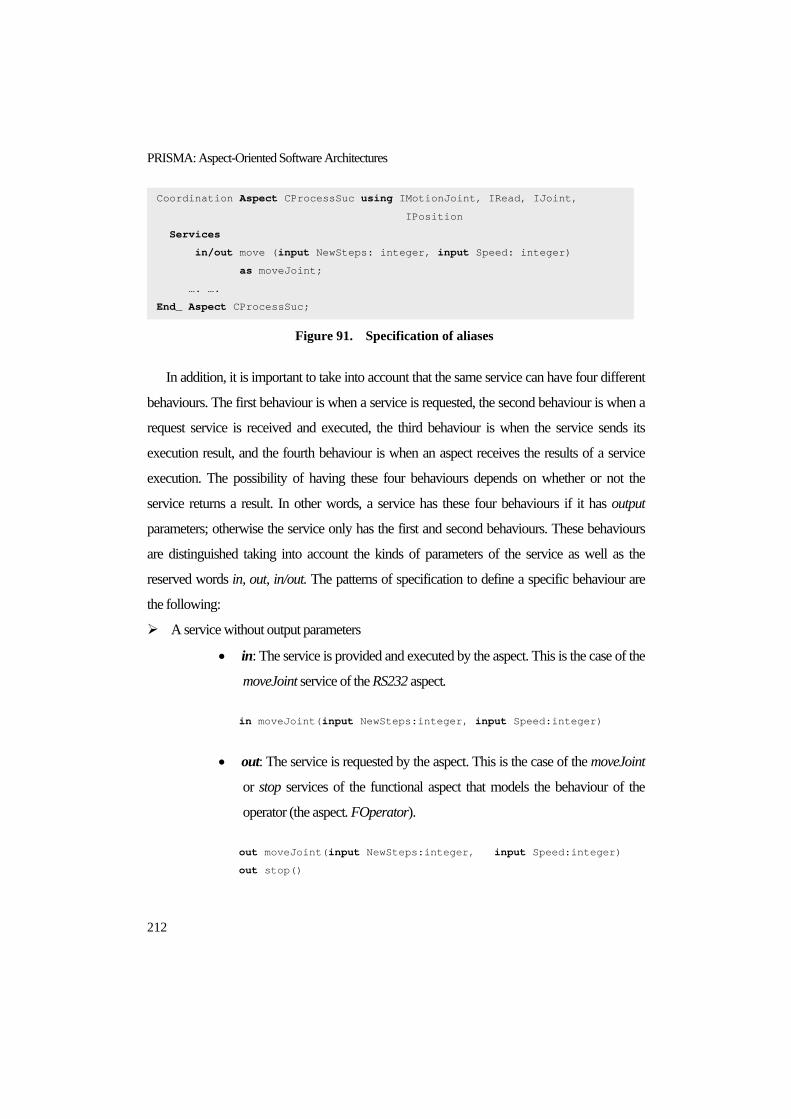
PRISMA: Aspect-Oriented Software Architectures
212
Figure 91. Specification of aliases
In addition, it is important to take into account that the same service can have four different
behaviours. The first behaviour is when a service is requested, the second behaviour is when a
request service is received and executed, the third behaviour is when the service sends its
execution result, and the fourth behaviour is when an aspect receives the results of a service
execution. The possibility of having these four behaviours depends on whether or not the
service returns a result. In other words, a service has these four behaviours if it has output
parameters; otherwise the service only has the first and second behaviours. These behaviours
are distinguished taking into account the kinds of parameters of the service as well as the
reserved words in, out, in/out. The patterns of specification to define a specific behaviour are
the following:
A service without output parameters
• in: The service is provided and executed by the aspect. This is the case of the
moveJoint service of the RS232 aspect.
in moveJoint(input NewSteps:integer, input Speed:integer)
• out: The service is requested by the aspect. This is the case of the moveJoint
or stop services of the functional aspect that models the behaviour of the
operator (the aspect. FOperator).
out moveJoint(input NewSteps:integer, input Speed:integer)
out stop()
Coordination Aspect CProcessSuc using IMotionJoint, IRead, IJoint,
IPosition
Services
in/out move (input NewSteps: integer, input Speed: integer)
as moveJoint;
…. ….
End_ Aspect CProcessSuc;

The PRISMA Aspect-Oriented Architecture Description Language
213
• in/out: This is the way of specifying that the service has both the in and out
behaviours without repeating the specification of the service, which means
that:
o The service is provided and executed by the aspect, and the service is also
requested by the aspect. This is the case of the moveJoint service of the
CProcessSuc aspect:
in/out moveJoint(input NewSteps:integer,
input Speed:integer)
A service with output parameters
• in/out: It defines two possible behaviours
o The service is provided and executed by the aspect (in), and the aspect
sends the results of the service execution (out). This is the case of the
check service of the SMotion aspect.
in/out check (input Degrees: integer,
output MovSecure: boolean)
o The service is requested by the aspect (out) and the aspect receives the
result of the service (in). This is the case of the moveOk service of the
CProcessSuc aspect.
in/out moveok(output Success: boolean);
As can be seen from these patterns, when the service does not have any output parameter,
the properties in, out and in/out define the behaviour of the services without ambiguities.
However, when the service has output parameters, the property in/out has two possible
meanings. This ambiguity disappears thanks to the definition of the service valuations
presented below.

PRISMA: Aspect-Oriented Software Architectures
214
8.1.2.3. Valuations A service can have one or more valuations associated to it (see Figure 90). Valuations specify
the changes in the value of attributes and parameters by the execution of services. The template
for specifying the service valuations is presented in Figure 92.
Figure 92. Specification template of valuations
The valuations of a service are preceded by the reserved word Valuations. The specification
of a valuation consists of three sections: condition, action and postcondition. A condition is
validated in the aspect state before its execution, and its specification is optional. The action
specifies the service that executes the action by specifying its name and the name of its
parameters. In addition, the action specifies the property in or out of the service in which the
valuation must be performed. The property that can be used in the valuation definitions
depends on the service specification, i.e., if the service has an in/out property it is possible to
define out valuations and in valuations; whereas if the service only has an out property or the
service only has an in property it is only possible to define out valuations or in valuations,
respectively.
The semantics of the valuation depends on the in and out properties and the use of the
parameters inside the valuation. The meaning of the postcondition is presented following the
same classification used above for the services properties and parameters.
A service without output parameters
• in: The service is provided and executed by the aspect.
o Valuation in: The postcondition must be satisfied after the service
execution.
• out: The service is requested by the aspect.
<valuations> ::= Valuations <valuation_seq>
<valuation> ::= [‘{‘ <condition> ‘}’] ‘[‘ <action> ‘]’ <postcondition_list>
<action> ::= <service_type> <service_name>‘(‘ [<parameter_name_list>]‘)’
<postcondition> ::= <property> ‘:=’ <formulae>
<property> ::= <attribute_name> | <parameter_name>

The PRISMA Aspect-Oriented Architecture Description Language
215
o Valuation out: The postcondition must be satisfied after the service
request
• in/out: The service is provided and executed by the aspect, and the service is
also requested by the aspect. In this case, it is possible to define the two kinds
of valuations:
o Valuation in: The postcondition must be satisfied after the service
execution
o Valuation out: The postcondition must be satisfied after the service
invocation
A service with output parameters
A service with output parameters always has an in/out behaviour. Its semantics varies
depending on the service is provided or requested.
• in/out: It defines two possible behaviours. To specify one behaviour or the
other, the valuation must be specified as is presented bellow:
o The service is provided and executed by the aspect, and the aspect sends
the results of the service execution.
Valuation in: The postcondition must be satisfied after the
service execution. The output parameters of the service cannot
be used as a right term of the valuation in any case, neither in the
condition nor in the postcondition, due to the fact that the service
has not been executed and its output parameters do not have
value. In fact, output parameters are usually used as a left term of
the postcondition in order to satisfy the condition that requires
output parameters to have a value after the service execution.
An example of this case is the check service of the SMotion
aspect that has two associated in valuations that define the state
of the aspect after the service execution. This is due to the fact

PRISMA: Aspect-Oriented Software Architectures
216
that the output parameter is not used as a right term of
conditions. In addition, the postcondition establishes the
condition that must be satisfied (left term) as a result of the
service execution (see Figure 93). In this case, the value of the
output parameter value must be equal to a specific value, either
true or false.
Figure 93. Specification of the service check
and its valuations
Valuation out: The postcondition must be satisfied after
sending the result. The semantics of the out valuation is
conditioned by the semantics of the in valuation. If the in obtains
a result, the out is related to sending the result. Since the service
has already been executed and the output parameters have value,
they can be used in the condition and in the right terms of
postcondition.
o The service is requested by the aspect and the aspect receives the result of
the service.
Valuation in: The postcondition must be satisfied after the
reception of the service result. Since the service has already been
executed and the output parameters have value, they can be used
in the condition and in the right terms of postcondition.
in/out check (input Degrees: integer,
output MovSecure: boolean);
Valuations
{(Degrees >= minimum) and (Degrees <= maximum)}
[in check (Degrees, MovSecure)]
MovSecure := true;
{(Degrees < minimum) or (Degrees > maximum)}
[in check (Degrees, MovSecure)]
MovSecure := false;
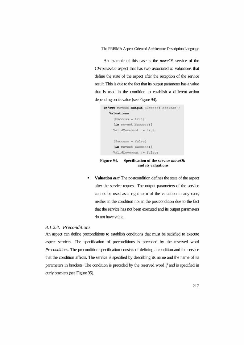
The PRISMA Aspect-Oriented Architecture Description Language
217
An example of this case is the moveOk service of the
CProcessSuc aspect that has two associated in valuations that
define the state of the aspect after the reception of the service
result. This is due to the fact that its output parameter has a value
that is used in the condition to establish a different action
depending on its value (see Figure 94).
Figure 94. Specification of the service moveOk
and its valuations
Valuation out: The postcondition defines the state of the aspect
after the service request. The output parameters of the service
cannot be used as a right term of the valuation in any case,
neither in the condition nor in the postcondition due to the fact
that the service has not been executed and its output parameters
do not have value.
8.1.2.4. Preconditions An aspect can define preconditions to establish conditions that must be satisfied to execute
aspect services. The specification of preconditions is preceded by the reserved word
Preconditions. The precondition specification consists of defining a condition and the service
that the condition affects. The service is specified by describing its name and the name of its
parameters in brackets. The condition is preceded by the reserved word if and is specified in
curly brackets (see Figure 95).
in/out moveok(output Success: boolean);
Valuations
{Success = true}
[in moveok(Success)]
ValidMovement := true,
{Success = false}
[in moveok(Success)]
ValidMovement := false;

PRISMA: Aspect-Oriented Software Architectures
218
An example of a precondition is the precondition of the CProcessSuc aspect shown in
Figure 96. In this case, the precondition establishes that the newPosition service can only be
executed if the validMovement attribute has the value true. This precondition defines that the
position of a joint is only modified when the movement has been successfully performed.
Figure 95. Specification template of preconditions
Figure 96. Specification of preconditions
8.1.2.5. Constraints An aspect can define constraints to condition the value of its attributes. The specification of
constraints is preceded by the reserved word Constraints. The constraint specification consists
of defining a static or dynamic condition (see Figure 97). If the condition is dynamic, it uses
ones of the temporal operators offered by the PRISMA AOADL: always, never, since, until,
and their possible combinations.
In the TeachMover, none of its aspects have the specification of a constraint. However, it is
possible to imagine a hypothetical constraint for the halfSteps attribute of the FJoint aspect, in
which it was specified that the halfSteps attribute must always contain a value higher than 10
(see Figure 98).
Coordination Aspect CProcessSuc using IMotionJoint, IRead, IJoint,
IPosition
… …
Preconditions
newposition(newHalfSteps) if (validMovement = true)
… …
End Aspect CProcessSuc;
<preconditions> ::= Preconditions <precondition_seq>
<precondition> ::= <invocation> if ‘{‘ <condition> ‘}’
<invocation> ::= <service_name>‘(‘ [<parameter_name_list>]‘)’

The PRISMA Aspect-Oriented Architecture Description Language
219
Figure 97. Specification template of constraints
Figure 98. Specification of constraints
8.1.2.6. Transactions An aspect can not only define simple services, it can also define complex services composed of
simple services and/or other complex services. These complex services are transactions due to
the fact that they are executed in a transactional way. In other words, the services that compose
a transaction are atomically executed (all or none). As a result, if the execution of one of the
transaction services fails, the execution of the services that have already been executed is
undone.
The specification of transactions is preceded by the reserved word Transactions. In the first
instance, the specification of a transaction consists of defining its name in capital letters and the
Functional Aspect FJoint using IPosition
Attributes
Variable
halfSteps: integer;
… …
Constraint
always {halfSteps > 10}
… …
End_Aspect FJoint;
<constraints> ::= Constraints <constraint_seq>
<constraint> ::= always ‘{‘ <condition> ‘}’ | never ‘{‘ <condition> ‘}’|
<condition_before> since <condition_after> |
<condition_before> until <condition_after> |
always <condition_before> since <condition_after> |
always <condition_before> until <condition_after> |
never <condition_before> since <condition_after> |
never <condition_before> until <condition_after> |
<condition_before> ::= <condition>
<condition_after> ::= <condition>

PRISMA: Aspect-Oriented Software Architectures
220
list of parameters that are necessary to execute the transaction. This list of parameters is
specified in brackets. In the second instance, the process that describes the transaction is
specified after a colon (see Figure 99). The process specification consists of a set of processes
that coordinate a set of services. These processes are specified and synchronized with each
other using the π-calculus with priorities (see section 5.2.2). Each one of these processes has a
name (channel) that identifies it and allows the rest of the states to call it. In the case of the first
transaction process, its name is always the transaction name.
Figure 99. Specification template of transactions
An example of a transaction is the transaction DANGEROUSCHECKING of the aspect
SMotion (see Figure 100). This transaction receives the needed information about the
movement as input parameters. It provides the information about whether or not the movement
is safe as a result of its execution. This transaction is composed of two checking services:
controlSpeed and check. First, controlSpeed is executed to check if the speed is suitable for the
movement; and second, check is executed to ensure that the movement is safe for the robot, the
operator, and the environment that surrounds them. The execution of these two services
<transactions> ::= Transactions <transaction_seq>
<transaction> ::= <service_type> <transaction_name>
‘(‘ [<param_service_list>] ‘)’‘:’
<initial_transaction_process> <transaction_process_seq>
[ <valuations> ]
<initial_transaction_process> ::= <transaction_name>‘::=’ <process> ‘ ’
<process_name>‘;’
<transaction_process> ::= <process_name> ::= <process> [‘ ’ <process_name> ]
<transaction_service> ::= [‘{’ <condition> ‘}’] <service_name> <channel_kind>
‘(‘ [<parameter_name_list> ]’)’
<channel_kind> ::= <input_channel> | <output_channel>
<input_channel> ::= ‘?’
<output_channel> ::= ‘!’

The PRISMA Aspect-Oriented Architecture Description Language
221
together determines whether or not the movement is safe. The result is specified by means of a
valuation that establishes the value of the Secure output parameter, and is based on the results
obtained by the simple services that compose the transaction.
Figure 100. Specification of transactions
Safety Aspect SMotion … …
Services … …
in/out check (input Degrees: integer, output MovSecure: boolean);
Valuations
{(Degrees >= minimum) and (Degrees <= maximum)}
[in check (Degrees, MovSecure)] MovSecure := true;
{(Degrees < minimum) or (Degrees > maximum)}
[in check (Degrees, MovSecure)] MovSecure := false;
in/out controlSpeed (input CurrentSpeed: integer,
output SpdSecure: boolean);
Valuations
{(CurrentSpeed >= 1) and (CurrentSpeed <= 180)}
[in controlSpeed (CurrentSpeed, SpdSecure)]
SpdSecure := true;
{(CurrentSpeed < 1) or (CurrentSpeed > 180)}
[in controlSpeed (CurrentSpeed, SpdSecure)]
SpdSecure := false;
Transactions
in/out DANGEROUSCHECKING (input Steps: integer,
input CurrentSpeed:integer, output Secure: boolean):
dangerousChecking = controlSpeed ! (CurrentSpeed, SpdSecure)
controlSpeed ? (CurrentSpeed, SpdSecure) CURRENTPOS;
CURRENTPOS = (POS_currentPosition ! (Pos)
POS_currentPosition ? (Pos)) SAFESTEPS;
SAFESTEPS = check ! (FTransHalfStepsToAngle (checkPos), MovSecure)
check ? (FTransHalfStepsToAngle (checkPos), MovSecure);
Valuations
{(MovSecure = true) and (SpdSecure = true)}
[in DANGEROUSCHECKING(Steps, CurrentSpeed, Secure)]
Secure := true;
{(MovSecure = false) or (SpdSecure = false)}
[in DANGEROUSCHECKING(Steps, CurrentSpeed, Secure)]
Secure := false; … …
End Aspect SMotion;

PRISMA: Aspect-Oriented Software Architectures
222
8.1.2.7. Played_Roles An aspect also defines the set of roles that can be played taking into account the semantics of
services. They are called played_roles and their definition is preceded by the reserved word
Played_Roles. A played_role specification consists of its name in capital letters and a process.
The process is specified using the dialect of π-calculus with priorities. Every service that
composes a played_role process belongs to the same interface. This interface is specified after
the played_role name with the reserved word for and the name of the interface (see Figure
101).
Figure 101. Specification template of played_roles
Figure 102. Specification of played_roles of the aspect CProcessSuc
For example, the CProcessSuc aspect defines some played_roles. Two of them are the ACT
and JOINT played_roles. ACT defines the client behaviour for the moveJoint and stop services,
i.e., it requests the services. Whereas, JOINT defines the server behaviour for these services,
and it also defines the client behaviour of the moveOk service (see Figure 102).
Coordination Aspect CProcessSuc using IMotionJoint, IRead, IJoint,
IPosition
… …
PlayedRoles
ACT for IMotionJoint ::= moveJoint ! (NewSteps, Speed) + stop ! ();
JOINT for IJoint ::= moveJoint ? (NewSteps, Speed) + stop ? () + moveOk ! (Success);
… …
End_Aspect CProcessSuc;
<played_roles> ::= Played_Roles <played_role_seq>
<played_role> ::= <played_role_name> for <interface_name> ‘=’
<process>‘;’
<played_role_service> ::= <service_name> <channel_kind>
‘(‘ [<parameter_name_list>]’)’

The PRISMA Aspect-Oriented Architecture Description Language
223
8.1.2.8. Protocols The language that has been used to specify protocols is a high-level language that is based on
the dialect of π- calculus with priorities. This high-level Language for PRISMA Protocols
(LPP) has been defined due to the fact that the PRISMA services are context-aware in
protocols. As a result, protocols must be specified taking into account the context of the service.
LPP introduces the context of a prefix using the π- calculus with priorities as a base
language. This prefix is an action that has been created because in PRISMA, it is sometimes
necessary to know the different contexts where a name is used (see Table 4). P_x Context of the name, where P is the process context and x is the
name of a service
All | * Every context
Table 4. Prefixes with Context of LPP
The context information is an important advantage to constrain the invocation of a name in
a specific context. The context of the name is added as a prefix of the name as P_x, with P
being the process context and x the name of the service. This expression might be confused
with a hierarchy; however, it is not a hierarchy. In fact, the name is not a hierarchical
composition of names as when the dot naming uses dots for naming (P.x). P_x is the complete
name and cannot be divided. This is syntactic sugar, which means that a name x is used in the
process P. In the case that this same name x is used by another process Q, it can be
distinguished by the expression Q_x. However, it is important not to lose sight of the fact that x,
P_x, and Q_x are the same names. As a result, this equivalence must be explicitly specified.
An example in which this action could be useful is the following:
<< In the business rules of a bank system, there is a process W that executes a set of internal
actions that allow the withdrawal of money from a bank account. This process can be invoked
with the withdrawal name. In addition, there are two different processes, VIPC and C. VIPC
describes the actions that a VIP customer of the bank can execute, and C describes the actions
that a normal customer of the bank can execute. Finally, the process B specifies the actions that
the bank can execute as well as the coordination rules of VIPC and C. The three processes

PRISMA: Aspect-Oriented Software Architectures
224
VIPC, C, and B can execute the W process using the prefix withdrawal!(). However, B must
establish when the withdrawal name can be requested by a VIP customer, a normal customer,
or the bank, depending on its state. Note that in the specification of the process B, there is no
way of distinguishing who is invoking the withdrawal from the process B: VIPC ::= … … + withdrawal !(money) VIPC + … …
C::= … … + withdrawal !(money) C + … …
B ::= … … + withdrawal !(money) B + … …
As a result, in B the context action is necessary to establish when the withdrawal can be
executed and by whom. The way of defining the different execution contexts of the W process
is by using the context action specified as VIPC_withdrawal!(), C_ withdrawal!(),
withdrawal!(). An example in which process B constrains the invocation of the withdrawal
name from the process VIPC is presented below. This constraint is defined using a variable that
provides the bank the information about whether or not there are VIP customers in the bank. VIPC ::= … … + withdrawal !(money) VIPC + … …
C::= … … + withdrawal !(money) C + … …
B ::= … … + if (ThereAreVIPCustomers) then BVIP else BC
+ … …
BVIP ::= (withdrawal !(money) + VIPC_withdrawal !(money)
+ C_withdrawal !(money)) B
BC::= (withdrawal !(money) + C_withdrawal !(money)) B
Being:
withdrawal !(money) = VIPC_ withdrawal !(money) = C_withdrawal !(money)
>>
In PRISMA, this action is necessary to specify protocols, which are the glue of the set of
services of the aspect and the different played_roles (processes) that have been defined inside
the aspect. To facilitate the definition of protocols, it is assumed that the context specifications
whose names are the same, without considering the context prefix, refer to the same name. As a
result, PRISMA performs this equivalence (P_x = Q_x = x) automatically in order to suitably
process the behaviour specified.
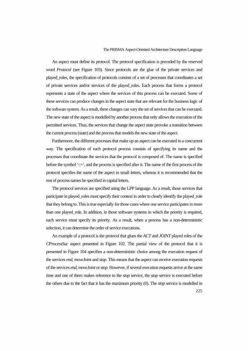
The PRISMA Aspect-Oriented Architecture Description Language
225
An aspect must define its protocol. The protocol specification is preceded by the reserved
word Protocol (see Figure 103). Since protocols are the glue of the private services and
played_roles, the specification of protocols consists of a set of processes that coordinates a set
of private services and/or services of the played_roles. Each process that forms a protocol
represents a state of the aspect where the services of this process can be executed. Some of
these services can produce changes in the aspect state that are relevant for the business logic of
the software system. As a result, these changes can vary the set of services that can be executed.
The new state of the aspect is modelled by another process that only allows the execution of the
permitted services. Thus, the services that change the aspect state provoke a transition between
the current process (state) and the process that models the new state of the aspect.
Furthermore, the different processes that make up an aspect can be executed in a concurrent
way. The specification of each protocol process consists of specifying its name and the
processes that coordinate the services that the protocol is composed of. The name is specified
before the symbol ‘::=’, and the process is specified after it. The name of the first process of the
protocol specifies the name of the aspect in small letters, whereas it is recommended that the
rest of process names be specified in capital letters.
The protocol services are specified using the LPP language. As a result, those services that
participate in played_roles must specify their context in order to clearly identify the played_role
that they belong to. This is true especially for those cases where one service participates in more
than one played_role. In addition, in those software systems in which the priority is required,
each service must specify its priority. As a result, when a process has a non-deterministic
selection, it can determine the order of service executions.
An example of a protocol is the protocol that glues the ACT and JOINT played roles of the
CProcessSuc aspect presented in Figure 102. The partial view of the protocol that it is
presented in Figure 104 specifies a non-deterministic choice among the execution request of
the services end, moveJoint and stop. This means that the aspect can receive execution requests
of the services end, moveJoint or stop. However, if several execution requests arrive at the same
time and one of them makes reference to the stop service, the stop service is executed before
the others due to the fact that it has the maximum priority (0). The stop service is modelled in

PRISMA: Aspect-Oriented Software Architectures
226
the example TeachMover with priorities since this service is used for emergency situations in
which the robot must be urgently stopped.
Figure 103. Specification template of protocols
Figure 104. Specification of the protocol of the aspect CProcessSuc
<protocol> ::= Protocol <initial_process> <protocol_process_seq>
<initial_process> ::= <aspect_name> ‘::=’ <process> ‘ ’ < process_name>‘;’
<protocol_process> ::= <process_name> ‘::=’ <process>
[‘ ’ <process_name>]
<protocol_service> ::= [‘{’ <condition> ‘}’] <protocol_service_type>
<channel_kind> ‘(‘ [<parameter_name_list>]’)’’:’
<priority>
<process_service_type> ::= <public_service> | <private_service>
<public_service> ::= <played_role_name>’_’<service_name>
<private_service> ::= <service_name>
<priority> ::= <priority_value>
Coordination Aspect CProcessSuc using IMotionJoint, IRead, IJoint,
IPosition
… …
Services
… …
in/out moveJoint(input NewSteps : integer, input Speed : integer)
in/out stop()
… …
Protocol
COORDJOINT ::= begin():1 --> MOTION
MOTION ::=end():1
+ (JOINT_moveJoint?(NewSteps, Speed):1
ACT_moveJoint!(NewSteps, Speed):1) MOTION
+ (JOINT_stop?():0
ACT_stop!():0) MOTION
… …
End_Aspect CoordJoint;

The PRISMA Aspect-Oriented Architecture Description Language
227
In addition to the non-deterministic choice, the protocol establishes that after the processing
of the execution request of the JOINT played_role, the same service must be requested using
the ACT played_role in order to be performed by the robot. In this case, the parameter values
are the same because their values have not been changed by their valuations. In this way, the
processes of both played_roles are coordinated by the protocol.
8.1.3. Simple Architectural Elements: Components and Connectors A simple architectural element is specified with the set of ports, the aspects it is formed of, and
the aspect weavings.
Figure 105. Specification template of simple architectural elements
<component> ::= Component <component_name>
<aspects_importation_seq>
[<weavings>]
<ports>
<creation>
<destruction>
End_Component <component_name>‘;’
<connector> ::= Connector <connector_name>
<aspects_importation_seq>
[<weavings>]
<ports>
<creation>
<destruction>
End_Connector <connector_name>‘;’
<aspects_importation> ::= <concern> Aspect Import <aspect_name>
<creation> ::= new‘(‘ [<param_service_list>]‘)’ ‘{‘ <start_aspects_seq> ‘}’
<destruction> ::= destroy‘(‘ ‘)’ ‘{‘ <stop_aspects_seq> ‘}’
<start_aspects> ::= <aspect_name>‘.’begin‘(‘ [<parameter_name_list>]‘)’ <stop aspects> ::= <aspect name>‘.’end‘(‘ ‘)’

PRISMA: Aspect-Oriented Software Architectures
228
The aspect specification in section 8.1.2 shows that an aspect definition does not include the
points where an aspect needs to coordinate with the other aspects (aspect weavings). This
independence of the aspect specification from other aspects and weavings makes aspects
reusable. Furthermore, the fact that the specification of weavings is inside architectural
elements provides the flexibility of specifying different behaviours of an architectural element
by importing the same aspects and defining different weavings. Therefore, when architectural
elements are defined, they import the aspect and define their weavings. An aspect weaving is
specified by determining the aspects that participate in the weaving, the services of the aspects
where they are weaved, and the weaving operators.
Components and connectors are simple architectural elements in PRISMA. Their
specification is performed in the same way; the only difference is the reserved words that
precede and end their specifications. These reserved words are Component…End_Component
and Connector…End_Connector for the specification of components and connectors,
respectively. The specification of simple architectural elements consists of a name, the
importation of needed aspects, the weavings among the aspects, a set of ports, and the two
sections that allow the creation and destruction of the architectural element (see Figure 105).
The importation of an aspect is specified by defining the concern and the name of the
aspect. Between the concern and the name, the reserved words Aspect Import must be specified
(see Figure 105).
Figure 106. Specification template of weavings
The weavings section is optional because an architectural element can import aspects
without having to synchronize them. The weaving section is preceded by the reserved word
<weavings> ::= Weavings <weaving_seq> End_Weavings’;’
<weaving>::= <aspect_name>’.’<service_name>‘(‘ [ <parameter_name_list> ]‘)’
<weaving_operator> <aspect_name>’.’<service_name>
‘(‘ [ <parameter_name_list>]‘)’
<weaving_operator> ::= after | before | instead | afterif‘(‘ <condition> ‘)’
| beforeif‘(‘ <condition> ‘)’ | insteadif‘(‘ <condition> ‘)’
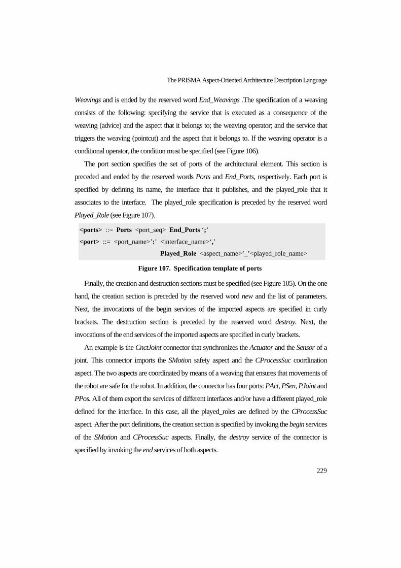
The PRISMA Aspect-Oriented Architecture Description Language
229
Weavings and is ended by the reserved word End_Weavings .The specification of a weaving
consists of the following: specifying the service that is executed as a consequence of the
weaving (advice) and the aspect that it belongs to; the weaving operator; and the service that
triggers the weaving (pointcut) and the aspect that it belongs to. If the weaving operator is a
conditional operator, the condition must be specified (see Figure 106).
The port section specifies the set of ports of the architectural element. This section is
preceded and ended by the reserved words Ports and End_Ports, respectively. Each port is
specified by defining its name, the interface that it publishes, and the played_role that it
associates to the interface. The played_role specification is preceded by the reserved word
Played_Role (see Figure 107).
Figure 107. Specification template of ports
Finally, the creation and destruction sections must be specified (see Figure 105). On the one
hand, the creation section is preceded by the reserved word new and the list of parameters.
Next, the invocations of the begin services of the imported aspects are specified in curly
brackets. The destruction section is preceded by the reserved word destroy. Next, the
invocations of the end services of the imported aspects are specified in curly brackets.
An example is the CnctJoint connector that synchronizes the Actuator and the Sensor of a
joint. This connector imports the SMotion safety aspect and the CProcessSuc coordination
aspect. The two aspects are coordinated by means of a weaving that ensures that movements of
the robot are safe for the robot. In addition, the connector has four ports: PAct, PSen, PJoint and
PPos. All of them export the services of different interfaces and/or have a different played_role
defined for the interface. In this case, all the played_roles are defined by the CProcessSuc
aspect. After the port definitions, the creation section is specified by invoking the begin services
of the SMotion and CProcessSuc aspects. Finally, the destroy service of the connector is
specified by invoking the end services of both aspects.
<ports> ::= Ports <port_seq> End_Ports ‘;’
<port> ::= <port_name>’:’ <interface_name>‘,’
Played_Role <aspect_name>’_’<played_role_name>

PRISMA: Aspect-Oriented Software Architectures
230
Figure 108. Specification of the connector CnctJoint
8.1.4. Attachments Attachment specifications define the connection among ports of components and connectors.
They can be specified inside systems (complex components) to connect the components and
connectors that compose systems or outside systems as part of the software architecture. They
are specified in the same way in both cases.
Connector CnctJoint
Coordination Aspect Import CProcessSuc;
Safety Aspect Import SMotion;
Weavings
SMotion. DANGEROUSCHECKING(NewSteps, Speed, Secure)
beforeif (Safe = true)
CProcessSuc.movejoint(NewSteps, Speed);
End_Weavings;
Ports
PAct : ImotionJoint,
Played_Role CProcessSuc.ACT;
PSen : IRead,
Played_Role CProcessSuc.SEN;
PJoint : IJoint,
Played_Role CProcessSuc.JOINT;
PPos : IPosition,
Played_Role CProcessSuc.POS;
End_Ports
new(input Argmin: integer, input Argmax: integer)
{CProcessSuc.begin();
SMotion.begin(input InitMinimum: integer,
input InitMaximum : integer); }
destroy(){
CProcessSuc.end();
SMotion.end();}
End_Connector CnctJoint;

The PRISMA Aspect-Oriented Architecture Description Language
231
Figure 109. Specification template of attachments
The specification of attachments is preceded and ended by the reserved words Attachments
and End_Attachments, respectively. Each attachment is specified by defining its name followed
by the specification of the connector port and the component port separated by the symbol ‘
’. The connector port specification consists of specifying the connector name, the port name
and the minimum and maximum cardinalities. The component port specification consists of
specifying the component name, the port name and the minimum and maximum cardinalities
(see Figure 109).
An example of an attachment is the attachment AttchActCnct that connects the CnctJoint
and the Actuator through their respective ports PAct and PCoord. In this case, their cardinalities
establish than only one attachment instance can be defined between the ports of the same
instances of CnctJoint and Actuator.
Figure 110. Specification of an attachment between the Actuator and the
CnctJoint
8.1.5. Systems The specification of systems permits the definition of architectural patterns that can be reused to
define the configuration of one or several software architectures. A system specification is
<attachments> ::= Attachments <attachment_seq> End_Attachments’;’
<attachment> ::= <attachment_name> ‘:’
<connector_name>’.’<port_name>
‘(‘ <card_min_value> ‘,’ <card_max_value >‘)’
‘ ’
<component_name>’.’<port_name>
‘(‘ <card_min_value> ‘,’ <card_max_value>‘)’
<card_min> := <natural_value>
<card_max> ::= <natural_value>
Attachments
AttchActCnct: CnctJoint.PAct(1,1) <--> Actuator.PCoord(1,1);
… …
End_Attachements;

PRISMA: Aspect-Oriented Software Architectures
232
preceded and ended by the reserved words System and End_System, respectively. The
specification of a system consists of a name, the importation of needed aspects, the weavings
among aspects, a set of ports, the importation of architectural elements, the attachments among
architectural elements, the bindings between the system and the architectural elements, and the
two sections create and destroy systems (see Figure 111). It is important to keep in mind that a
system can be defined without aspects and weavings, attachments or bindings. As a result,
these sections of the system specification are optional.
Systems import aspects and define the weavings among these aspects in the same way as
simple architectural elements (see Figure 105 and Figure 106). The ports of the system are
specified in the same way that it is presented in Figure 107. In addition, the set of architectural
elements, that are necessary to define the system are imported, and the number of instances that
can be specified at configuration time are constrained. These architectural elements can be
components, connectors and other systems, and their specification is defined by specifying the
name and the minimum and maximum number of instances that can be created for each
architectural element at configuration time.
Moreover, the connections among the different types of architectural elements are specified
in order to define the architectural pattern of the system. The attachments inside a system are
defined in the same way that is presented in section 8.1.4. The bindings among the system ports
and the connector or/and component ports that the system is composed of are specified.
The specification of bindings is preceded and ended by the reserved words Bindings and
End_Bindings, respectively. Each binding is specified by defining its name followed by the
specification of the system port and the architectural element port separated by the
symbol ‘ ’. The system port specification consists of specifying the port name and the
minimum and maximum cardinalities, whereas the architectural element port specification
consists of specifying the architectural element name, the port name, and the minimum and
maximum cardinalities (see Figure 112).

The PRISMA Aspect-Oriented Architecture Description Language
233
Figure 111. Specification template of systems
Figure 112. Specification template of bindings
Finally, the creation and destruction sections must be specified (see Figure 113). These
sections specify the signature of the services for creating the system at configuration time.
These sections establish the parameters and requests required to correctly create the elements
that compose the system. Then, the parameters and requests are instantiated at configuration
time. The creation section is preceded by the reserved word new, the list of parameters when
the system imports aspects, and the list of the number of instances of each architectural element
or channel of the system. This number establishes the exact number of instances that must be
<bindings> ::= Bindings <binding_seq> End_Bindings’;’
<binding> ::= <binding_name> ‘:’ <port_name>‘(‘ <card_min_value> ‘,’
<card_max_value>‘)’ ‘ ’ <architectural_element>’.’<port_name>
<system> ::= System <system_name>
[<aspects_importation_seq>]
[<weavings>]
<ports>
<architectural_element_importations>
[<attachments>]
[<bindings>]
<system_creation>
<system_destruction>
End_System <system_name>‘;’
<architectural_element_importations> ::= Import Architectural Elements
<architectural_element_import_list>‘;’
<architectural_element_import> ::= <architectural_element> ‘(‘<min_number_value>
‘,’ <max_number_value>‘)’
<architectural_element > ::= <component_name> | <connector_name> |
<system name>

PRISMA: Aspect-Oriented Software Architectures
234
created for each architectural element, attachment and binding at configuration time. Then, the
requests of the begin services of the imported aspects and the requests of the new services of
architectural elements, attachments and bindings are specified in curly brackets. The begin
service of aspects requires the parameters that are necessary in order to start the execution at
configuration time. The new service of architectural elements also requires the value of the
parameters that are necessary in order to create the architectural element. The new services of
binding and attachments relationships need to know the instance name of the instances that
they connect at configuration time.
The destruction section is preceded by the reserved word destroy(). Then, the requests of
the end services of the imported aspects and the destroy services of the architectural elements,
attachments and bindings are specified in curly brackets. With regard to the attachment and
binding creation, the template fixes the parameters. This is due to the fact they always have the
same number of parameters, and the only thing that varies is the name of the instances that they
connect.
An example is the Joint system, which imports a functional aspect that allows the system to
manage its position (see Figure 41). It has a port (PJoinSystem) to communicate with external
architectural elements (see section Ports, Figure 41). The Joint is composed of an Actuator, a
Sensor, and a CnctJoint connector that synchronizes them (see section Import Architectural
Elements, Figure 41). In addition, since it has a functional aspect that needs to communicate
with the CnctJoint in order to suitably update the joint position, a component that acts as a
wrapper of the functional aspect has been specified. This component wrapper is called
WrappAspSys and permits the communication between the aspect of the system and the
CnctJoint through an attachment (see section 6.2.12).This attachment (AttchPos) and two more
attachments have been defined to communicate the Actuator with the CnctJoint (AttActCnct)
and the Sensor with the CnctJoint (AttSenCnct) (see the Attachments section, Figure 41).Also, a
binding (BndJCnct) has been defined to publish the services of the CnctJoint through the
PJoint port to the exterior of the Joint (see the Bindings section, Figure 41).

The PRISMA Aspect-Oriented Architecture Description Language
235
Figure 113. Specification template of the creation and destruction of systems
<system_creation> ::= new ‘(‘ [<param_service_list>‘,’]
<architectural_element_number_list>
[’,’ <attachment_number_list>’,’ <binding_number_list>] ‘)’
‘{‘[<start_aspects_seq>]<architectural_elements_creation_seq>
[<attachments_creation_seq>] [<bindings_creation_seq>] ‘}’
<architectural_element_number> ::= input Num_<architectural_element_name>‘:’
natural
<attachment_number> ::= input Num_<attachment_name>‘:’ natural
<binding_number> ::= input Num_<binding_name>‘:’ natural
<architectural_elements_creation > ::= new <architectural_element_name>
‘(‘ [<param_service_list>]‘)’
<attachments_creation > ::= new <attachment_name> ‘(‘<param_attachment>‘)’
<param_attachment > ::= input ArgCnctName: string, input ArgCnctPort: string,
input ArgCompName: string, input ArgCompPort: string
<bindings_creation > ::= new <binding_name> ‘(‘ <param_binding> ‘)’
<param_binding > ::= input ArgSysPort: string, input ArgAEName: string,
input ArgAEPort: string
<system_destruction> ::= destroy ‘(‘ ‘)’ ‘{‘ [<stop_aspects_seq>]
<architectural_elements_destruction_seq>
[<attachments_destruction_seq>] [<bindings_creation_seq>] ‘}’
<architectural_elements_destruction> ::=
<architectural_element_name> ’.’ destroy‘(‘ ‘)’
<attachments_destruction > ::= <attachment_name>’.’destroy‘(‘ ‘)’
<bindings_destruction > ::= <binding_name>’.’destroy‘(‘ ‘)’
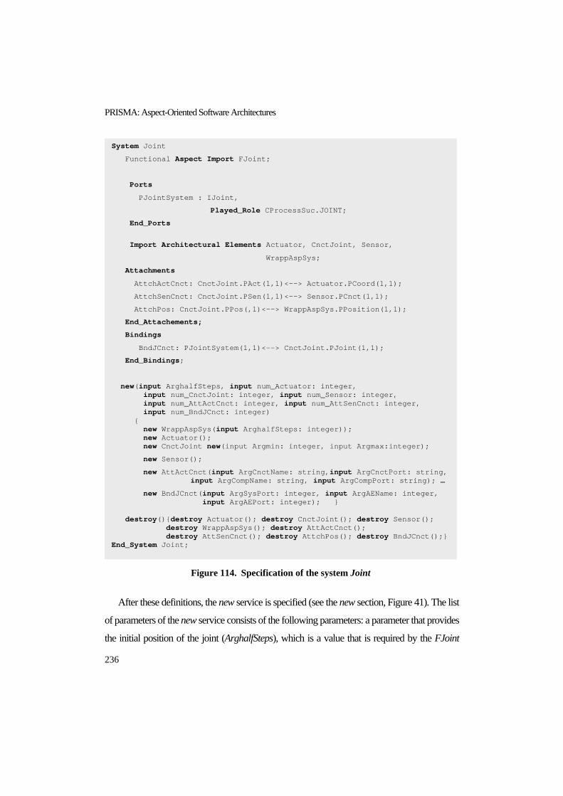
PRISMA: Aspect-Oriented Software Architectures
236
Figure 114. Specification of the system Joint
After these definitions, the new service is specified (see the new section, Figure 41). The list
of parameters of the new service consists of the following parameters: a parameter that provides
the initial position of the joint (ArghalfSteps), which is a value that is required by the FJoint
System Joint
Functional Aspect Import FJoint;
Ports
PJointSystem : IJoint,
Played_Role CProcessSuc.JOINT;
End_Ports
Import Architectural Elements Actuator, CnctJoint, Sensor,
WrappAspSys;
Attachments
AttchActCnct: CnctJoint.PAct(1,1)<--> Actuator.PCoord(1,1);
AttchSenCnct: CnctJoint.PSen(1,1)<--> Sensor.PCnct(1,1);
AttchPos: CnctJoint.PPos(,1)<--> WrappAspSys.PPosition(1,1);
End_Attachements;
Bindings
BndJCnct: PJointSystem(1,1)<--> CnctJoint.PJoint(1,1);
End_Bindings;
new(input ArghalfSteps, input num_Actuator: integer, input num_CnctJoint: integer, input num_Sensor: integer, input num_AttActCnct: integer, input num_AttSenCnct: integer, input num_BndJCnct: integer) { new WrappAspSys(input ArghalfSteps: integer)); new Actuator(); new CnctJoint new(input Argmin: integer, input Argmax:integer);
new Sensor();
new AttActCnct(input ArgCnctName: string,input ArgCnctPort: string, input ArgCompName: string, input ArgCompPort: string); …
new BndJCnct(input ArgSysPort: integer, input ArgAEName: integer, input ArgAEPort: integer); } destroy(){destroy Actuator(); destroy CnctJoint(); destroy Sensor(); destroy WrappAspSys(); destroy AttActCnct(); destroy AttSenCnct(); destroy AttchPos(); destroy BndJCnct();} End_System Joint;

The PRISMA Aspect-Oriented Architecture Description Language
237
aspect, and the parameters that provide the cardinalities of each architectural element, binding,
and attachment of the system. These cardinalities allow the Joint to know how many instances
of each type must be created at configuration time.
Note that there are no parameters to provide the cardinalities for the WrappAspSys and the
AttchPos. This is due to the fact that they are not architectural elements and attachments of the
software system. They are mechanisms that are created on purpose in order to permit the
communication between the system aspects and the architectural elements of the system. They
are only instantiated once.
The Joint new service specifies the request of the begin service of its imported aspects and
the new services of architectural elements, attachments and bindings that the joint includes (see
the new section, Figure 41). Since a wrapper is used for the system aspects, the begin service of
the FJoint aspect is invoked through the new service of the WrappAspSys. In addition, the
request of the new services for the CnctJoint, Sensor, Actuator, AttActCnct, BndJCnct, etc, are
specified. Those new services that need parameters to be properly instantiated must also be
specified. A clear example is the CnctJoint, which need a set of parameters to provide a value
to some of the attributes of the SMotion aspect (see Figure 88).
Finally, the destroy service of the Joint is specified by invoking the destroy services of the
architectural elements that it imports.
8.2. THE CONFIGURATION LEVEL The configuration level is used to define a specific architectural model for a software system. In
order to do this, all required connector, component and system types should be instantiated.
Then, all attachment and binding instances should be connected among these type instances. At
this point, the new services are instantiated and the constraints that have been defined for
systems are validated in order to ensure pattern satisfaction.

PRISMA: Aspect-Oriented Software Architectures
238
Figure 115. Specification template of configurations of architectural models
The architectural model specification is preceded by the reserved word
Architectural_ModelConfiguration and the name of the architectural model configuration. The
specification of the new service is defined in curly brackets and is preceded by the reserved
word new and the architectural model name. The specification of the new service consists of
the request of the new services of the architectural elements, attachments and bindings that
compose the configuration in order to instantiate them.
<architectural_model_configuration> ::= Architectural_Model_Configuration
<configuration_name> ‘=’ new <model_name> ‘{‘ <components_instantiation_seq>
[<systems_instantiation_seq>] <connectors_instantiation_seq>
<attachments_intantiation_seq> ‘}’
<components_instantiation> ::= <component_instance_name> ‘=’ new
<component_name>‘(‘ [<param_value _list> ] ‘)
<connectors_instantiation> ::= <connector_instance_name> ‘=’ new
<connector_name> ‘(‘ [<param_value_list> ] ‘)
<attachments_instantiation> ::= <attachment_instance_name>1 ‘=’ new
<attachment_name> ‘(‘<param_attachment_value>‘)’
<systems_instantiation> ::= <system_instance_name>1 ‘=’ new <system_name>
‘(‘[<param_service_value_list>‘,’] <architectural_element_number_value_list>,
[<attachment_number_value_list>’,’ <binding_number_value_list>] ‘)’
‘{‘ [<start_aspects_seq>] <architectural_elements_instantiation_seq>
<attachments_instantiation_seq> <bindings_instantiation_seq> ‘}’
<architectural_element_instantiation > ::= <components_instantiation> |
<connectors_instantiation> |
<systems_instantiation>
< bindings_instantiation> ::= <binding_instance_name>1 ‘=’ new
<binding_name> ‘(‘ <param_binding_value> ‘)’
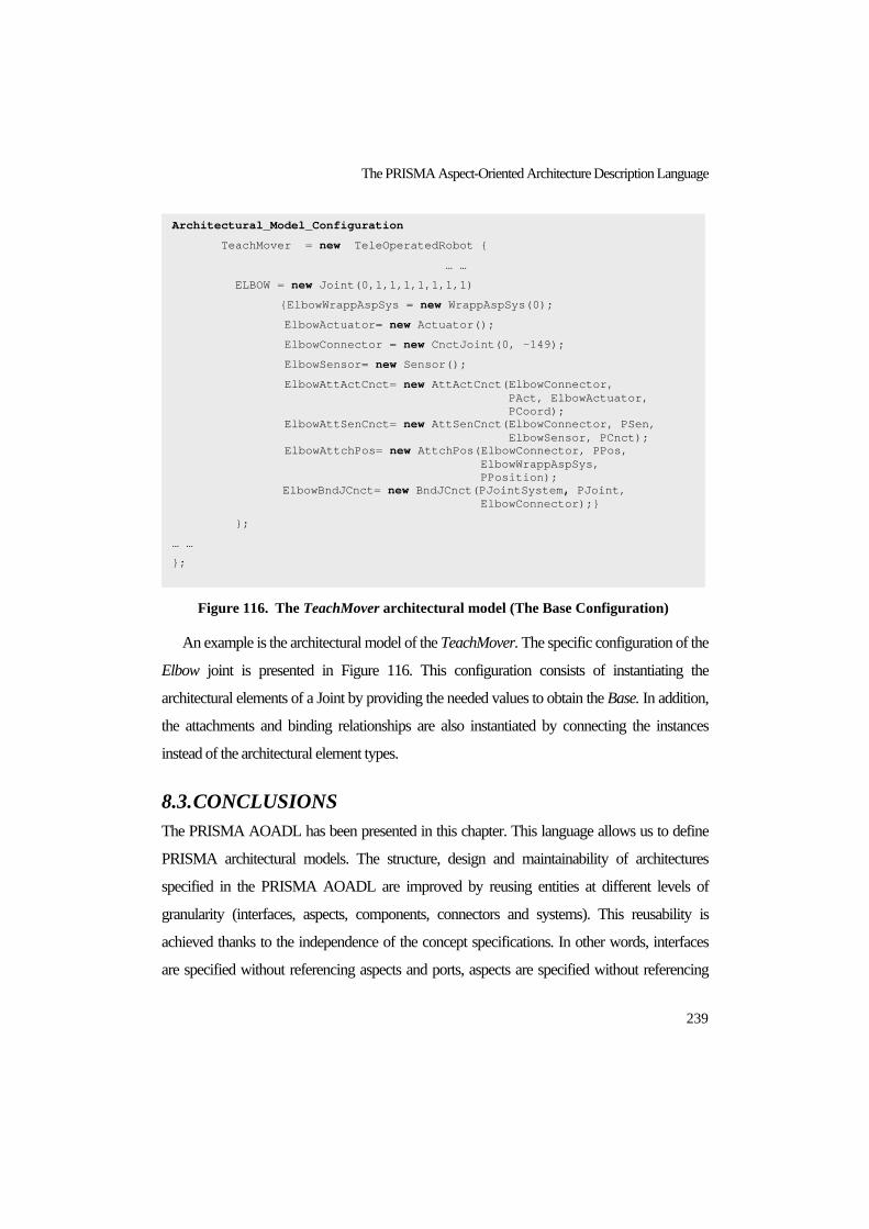
The PRISMA Aspect-Oriented Architecture Description Language
239
Figure 116. The TeachMover architectural model (The Base Configuration)
An example is the architectural model of the TeachMover. The specific configuration of the
Elbow joint is presented in Figure 116. This configuration consists of instantiating the
architectural elements of a Joint by providing the needed values to obtain the Base. In addition,
the attachments and binding relationships are also instantiated by connecting the instances
instead of the architectural element types.
8.3. CONCLUSIONS The PRISMA AOADL has been presented in this chapter. This language allows us to define
PRISMA architectural models. The structure, design and maintainability of architectures
specified in the PRISMA AOADL are improved by reusing entities at different levels of
granularity (interfaces, aspects, components, connectors and systems). This reusability is
achieved thanks to the independence of the concept specifications. In other words, interfaces
are specified without referencing aspects and ports, aspects are specified without referencing
Architectural_Model_Configuration
TeachMover = new TeleOperatedRobot {
… …
ELBOW = new Joint(0,1,1,1,1,1,1,1)
{ElbowWrappAspSys = new WrappAspSys(0);
ElbowActuator= new Actuator();
ElbowConnector = new CnctJoint(0, -149);
ElbowSensor= new Sensor();
ElbowAttActCnct= new AttActCnct(ElbowConnector, PAct, ElbowActuator, PCoord); ElbowAttSenCnct= new AttSenCnct(ElbowConnector, PSen, ElbowSensor, PCnct); ElbowAttchPos= new AttchPos(ElbowConnector, PPos, ElbowWrappAspSys, PPosition); ElbowBndJCnct= new BndJCnct(PJointSystem, PJoint, ElbowConnector);}
};
… …
};

PRISMA: Aspect-Oriented Software Architectures
240
other aspects or architectural elements, and architectural elements are specified without
referencing other architectural elements. The references among aspects are specified by means
of weavings, and the references among architectural elements are specified using attachments
and bindings. Therefore, an interface can be reused by several aspects and ports; an aspect can
be reused by several architectural elements and can be synchronized in different ways and with
different aspects inside these architectural elements; and an architectural element can be
attached and bound to several architectural elements.
This reusability is also improved by means of the division of the language into two levels of
abstraction: types and configuration. The types defined at the type definition level can be reused
by the configuration level to specify different software architectures such as the TeachMover,
EFTCoR, etc. At the same time, the division of the language into two levels of abstraction
provides two more important advantages. One of the advantages is the fact that it is possible to
independently manage types and the specific configuration of an architectural model, which
improves the reusability of types and the maintenance of the system. The other advantage is
that it is possible to easily differentiate between a change in a type and a change in the
configuration of the architecture. As a result, this provides a suitable framework to introduce
evolution mechanisms at two different levels of abstraction: types and configuration.
In addition, the fact that the PRISMA AOADL integrates AOSD in software architectures
provides better maintenance. This is due to the fact software architectures are well modularized
by a functional decomposition; however, in PRISMA this modularization has been improved
by the specification of the crosscutting-concerns inside aspects. Thus, if a change in the features
of a specific concern is required, it would only be necessary to modify or change the aspect that
defines the concern, and every architectural element that imports it will automatically be
updated. As a result, the changes of the functionality are well located thanks to the architectural
elements, and the changes of crosscutting-concerns are well located thanks to aspects.
It is important to take into account that most ADLs only permit the specification of the
skeleton of architectures and the services that are interchanged among their different
architectural elements. The PRISMA AOADL has greater expressive power and can specify

The PRISMA Aspect-Oriented Architecture Description Language
241
more features and requirements using aspects. This complete specification of the system
requirements facilitates code generation.
Finally, it is important to emphasize that the PRISMA AOADL is a formal language that
allows the validation and verification of PRISMA architectural models and facilitates the task
of automatically generating code from its specifications. Since PRISMA AOADL is a
language independent of the technology, the same PRISMA architectural model can also be
compiled into different programming languages and technologies, thereby reducing
development time and preserving the traceability between an architectural model and its
application code.
The work related to the PRISMA ADL has produced a set of results that have been
materialized in the following publications:
Jennifer Pérez, Nour Ali, Jose Ángel Carsí, Isidro Ramos, Designing Software
Architectures with an Aspect-Oriented Architecture Description Language, 9th
Symposium on the Component Based Software Engineering (CBSE), Springer Verlang
LNCS 4063 ,pp. 123-138, ISSN: 0302-9743, ISBN: 3-540-35628-2, Vasteras, Suecia,
June 29th-July 1st, 2006.
Jennifer Pérez, Isidro Ramos, OASIS as a Formal Support for the Dynamic, Distributed
and Evolutive Hypermedia Models, Technical Report DSIC-II/22/03, pp. 144, Polytechnic
University of Valencia, October 2003. (In Spanish)

PRISMA: Aspect-Oriented Software Architectures
242

PART V
THE PRISMA FRAMEWORK
“Van Gogh Painting Sunflowers”, Paul Gauguin, 1888


The PRISMA CASE
245
CHAPTER 9 9. THE PRISMA CASE
<< Knowledge is a treasure, but practice is the key to it. >>
Thomas Fuller
Some new approaches have recently emerged in order to improve software development. Their
common characteristic is that they try to improve the early stages of the software life cycle by
automating their activities as much as possible by following Model-Driven Development
(MDD). MDD is a software development paradigm that is based on models that use automatic
generation techniques in order to obtain the software product. MDD is included within Model–
Driven Engineering (MDE), which increases the variety of software artefacts that can be
represented as models (ontologies, UML models, relational schemas, XML schemas, etc). The
use of models to develop software provides solutions that are independent of technology,
whose source code can be obtained by means of automatic code generation techniques for
different technologies and programming languages. The high level of abstraction that models
provide permits working with metamodels in the same way as with specific models or domain-
specific models.
Since the PRISMA model is a technology-independent model, the PRISMA approach
follows the MDD paradigm to obtain its advantages during the development and maintenance
processes of PRISMA architectures. The main goal of the PRISMA approach is to give
support to the development of technology-independent aspect-oriented software architectures,
which could be compiled for different technological platforms and languages using automatic
code generation techniques. A PRISMA CASE has been developed to give support to the

PRISMA: Aspect-Oriented Software Architectures
246
PRISMA approach following the MDD paradigm. PRISMA CASE currently supports the
generation of aspect-oriented C# code that is executable on .NET technology. The PRISMA
CASE is composed of the PRISMA metamodel, a graphical modelling tool, a model compiler,
and a middleware (see Figure 117).
Figure 117. PRISMA CASE
The PRISMA metamodel is part of the PRISMA CASE since the metaclassess that allow
the creation of PRISMA aspect-oriented software architectures, as well the OCL rules of the
PRISMA metamodel, must be available in the CASE tool. They are necessary to be able to
model PRISMA architectural models and to make sure that they satisfy the PRISMA model.
The PRISMA AOADL is a formal language. Even though the use of a formal language
clearly provides advantageous characteristics, the use of a formal language is really difficult.
For this reason, PRISMA CASE provides a graphical language and a graphical modelling tool
to model PRISMA software architectures using an intuitive and friendly graphical AOADL

The PRISMA CASE
247
Since PRISMA CASE must generate executable C# code in .NET technology and the
.NET framework does not provide support for the Aspect-Oriented approach, this thesis
presents a .NET middleware that has been developed to provide a solution. This middleware is
called PRISMANET. PRISMANET extends the .NET technology through the execution of
aspects on the .NET platform in accordance with the PRISMA model.
Finally, the PRISMA model compiler has been developed to automatically generate C#
code from the PRISMA architectural models that are defined using PRISMA CASE.
This chapter presents the PRISMA CASE in detail. First, it is explained how the PRISMA
CASE supports the metamodel and how the modelling tool gives support to the graphical
PRISMA AOADL. Second, the PRISMA model compiler and its code generation patterns are
introduced. Then, the chapter explains how the configuration of software architectures is
integrated in PRISMA CASE and how PRISMA configurations can be executed. Finally, the
PRISMANET middleware is presented to show how the execution of PRISMA software
architectures is supported by the .NET platform.
9.1. GRAPHICAL MODELLING TOOL The PRISMA CASE provides a graphical language and a modelling tool to support more
intuitive and friendly aspect-oriented software architecture modelling. However, a formal
specification is more suitable for some details of PRISMA specifications; for instance, the
specification of formulae such as valuations or preconditions. Thus, only the main concepts and
their relationships are graphically specified; the rest of the concepts are represented using the
AOADL (see chapter 8 and appendix A), and their specifications are included in the definition
of the corresponding graphical shapes.
9.1.1. PRISMA UML Profile UML is a standard of the OMG and a widely extended notation [UML06]. These
characteristics make graphical notations based on UML more understandable to users. There
are a wide variety of tools based on UML that interchange UML models using XMI
documents and provide extension mechanisms. This means there is no need to develop a tool

PRISMA: Aspect-Oriented Software Architectures
248
from scratch in order to create a customized tool. Therefore, UML was initially chosen as a
graphical notation for PRISMA.
Although UML is intended for object-oriented modelling, thanks to its extension
mechanisms that are associated to the definition of a UML profile, it can be customized to the
particular needs of new models. These extension mechanisms are stereotypes, tagged values,
and constraints, which are all used to define new derived concepts (metaclasses) from the
standard UML metaclasses. Thus, a set of specific extensions is called a UML profile.
A PRISMA profile was developed not only to have a graphical notation that follows a
standard, but also to achieve the PRISMA support by any modelling tool that supports UML or
XMI documents. This profile includes all the necessary extensions for using UML as a
graphical notation for PRISMA specifications. It has been implemented by extending the
metaclasses of the UML metamodel version 1.5. and by preserving the satisfaction of the
requirements that Aldawud stated for defining a UML profile for AOSD. This extension is
necessary because, despite the fact that UML 1.5 includes the following concepts: component,
connector and interface (required or provided), the provided expressivity is too basic in
comparison with PRISMA. Furthermore, UML 1.5. does not include the aspect, port, weaving,
attachment and binding concepts. A simplified version of the PRISMA UML profile is
presented in appendix B.
One of the advantages of defining a UML profile is that modelling tool support can be
easily obtained by means of available tools based on UML, such as Rational Rose [RAT06],
Argo UML [ARG06], Visio [VIS06], etc. Most of them provide mechanisms to extend their
functionality. This means that there is no need to develop a tool from scratch but that any of the
existing ones can be extended. Several of these tools were considered and reviewed as support
for PRISMA modelling, but Visio was finally selected for the following reasons:
1. Visio allows straightforward management, both for using and modifying shapes. This
characteristic is highly relevant for PRISMA purposes because all the kinds of concepts
that are included in the PRISMA profile can easily have different shapes related to their
functionality.

The PRISMA CASE
249
2. Visio provides an add-in to translate a UML model to XMI. This means that other
tools such as those listed in [OCL06] can be used for semantic analysis. This provides for
simple consistency checks and type checking in terms of defined OCL constraints of the
PRISMA profile.
A lightweight extension of Visio called EGV-PRISMA was developed by means of a
template to support the above mentioned needs of the PRISMA profile [Per06b], [Per06a].
However, Visio does not provides a repository where the PRISMA metamodel can be
introduced and where its constraints can be verified during the modelling process. The models
can only be semantically verified when the model is finished, using other tools such as the ones
that appear in [OCL06]. Furthermore, Visio does not provide mechanisms to develop a model
compiler that automatically generates the source code from the graphical models.
Since Visio does not provide a framework that could support all the requirements that a
PRISMA analyst has, the selection of another tool that would support these needs was
mandatory. As a result, DSL tools were selected to develop the PRISMA framework because
they provide specific mechanisms to define models, graphical support and code generation
templates. However, DSL tools are not based on a standard such as UML, an ad-hoc graphical
AOADL has been defined for the PRISMA CASE.
9.1.2. Domain-Specific Language Tools (DSL Tools) The PRISMA approach follows the MDD paradigm. There are two main approaches that
apply this paradigm. They are the Model-Driven Architecture (MDA) approach proposed by
the OMG [MDA06], and the Software Factories approach proposed by Microsoft [Gre04].
MDA deals with the lack of software system adaptation to different technologies and
programming languages. Software Factories leads to the reuse of architectures, software
components, techniques and tools to improve software development. The set of tools and
techniques that give support this approach are integrated into DSL Tools (Domain Specific
Languages Tools) [DSL06].
DSL Tools is the framework that has been selected to develop and support the development
of PRISMA aspect-oriented software architectures. It is a set of tools for creating, editing,

PRISMA: Aspect-Oriented Software Architectures
250
visualizing, and using domain-specific models to automate and improve the software
development process (see Figure 118). This set of tools is integrated into the Visual Studio
2005 framework to define domain models with their customized graphical representations. The
tools and mechanisms that compose this framework are the following:
Project wizard: The framework allows you to define your own customized solution
where the specific model, its graphical representation and its code generators are defined.
Its integration inside the Visual Studio 2005 permits the validation of the generated code
by executing it in the framework. The wizard requires the choice of one of the templates
that it offers on which to base the definition of a domain model.
There are currently four templates available:
o Minimal Language: This is the generic template for the definition of any
domain model.
o Activity Diagrams: This is a template for the activity diagrams of UML
o Class Diagrams: This is a template for the class diagrams of UML
o Use Case Diagrams: This is a template for the use cases diagrams of UML
Model designer: The Model Designer tool creates a domain model project and permits
the definition of a domain model associated to this project. In the domain model, concepts
are represented in a graphical way by classes and relationships (see Figure 118). Classes
have value properties and participate in relationships. A domain model defined in the
model designer is translated to .NET Framework classes. These C# classes are provided
with an interface to access and update value properties, to navigate across relationships,
and to enable an object to participate in a relationship. In addition, the classes can be
extended to introduce verification and validation rules depending on whether the domain
model is a meta-model or a model, respectively.

The PRISMA CASE
251
Figure 118. DSLTools Framework: Domain Model of PRISMA
Graphical designer: The Model Designer tool stores the definition of the domain model
in an XML document (see Solution Explorer in Figure 118). In this XML document, the
design decisions and the graphical representation of each one of the concepts of the model
can be defined without any manual coding. These definitions have an effect on the
generated solution, where it is possible to define specific models following the domain
model defined in the domain model project. The Graphical Designer tool creates the
designer project, i.e., the diagram types that are associated to a domain model, the concepts
that can be drawn in each diagram as well as the shapes that are associated to each concept
and the toolboxes.
Other projects: In addition to the two predefined Domain Model and Designer projects,
DSL can add as many projects as necessary to develop a customized modelling tool.
Once the DSL solution has been completely defined, it can be compiled and executed. As a
result, a modelling tool for the domain specific model that has been defined is generated. This

PRISMA: Aspect-Oriented Software Architectures
252
tool is called Debugging Solution. This generated tool provides a customized toolbox, a tree
that is organized according to the metamodel in which concepts can be queried and updated,
mechanisms for browsing through the tree, and mechanisms to update and query the properties
of the defined concepts. This solution not only provides a customized modelling tool, it also
provides a new project in its solution explorer called Code Generation Designer, which
provides a set of templates in order to automatically generate the code using a set of code
generators. These templates help users to define a model compiler in an easy way by browsing
through the concepts that have been modelled and stored in the metamodel (DSL Domain
Model). The DSL code generators take the templates, the domain model definition and its
XML document as inputs of the code generation process. The output of this process is
generated by the code generators following the defined templates and substituting the
parameters for the concepts stored in the metamodel.
9.1.3. PRISMA as a Domain-Specific Language DSL tools have been created to model specific models such as the model of a web page, a
banking system, a tele-operated system, etc. The debugging solution of this model is then used
to define specific web pages, banks systems, tele-operated systems with domain-specific tool
boxes and concepts that have been defined in the Domain Model and the Designer projects.
However, the PRISMA model is a metamodel that permits the definition of PRISMA models
whose instantiation defines specific systems. In this sense, PRISMA has taken a step forward.
In PRISMA, DSL tools are used to define a metamodel as a domain-specific language, i.e.,
aspect-oriented software architectures are defined as a domain-specific model.
In order to develop PRISMA CASE, a DSL project has been generated using the Minimal
Language template (see section 9.1.2).This is the template that provides mechanisms for
introducing the PRISMA metamodel in DSL Tools. The predefined projects DomainModel
and Designer are generated as a result of this template selection.
The project DomainModel provides a toolbox to define the domain-specific model in DSL
(see Figure 119). In PRISMA, every metaclass and relationship of the PRISMA metamodel is

The PRISMA CASE
253
been introduced in the domain model. For example, Figure 120 shows the definition of the
architectural element and aspect concepts in the DomainModel.
Figure 119. Toolbox of the Domain Model
(a) Architectural Element (b) Aspect
Figure 120. Definition of Architectural Elements and Aspects in the DomainModel of DSL
All the classes of the PRISMA domain model are translated to partial C# classes in order to
access and update value properties, to navigate across relationships, and to enable an object to
participate in a relationship. These partial classes can be implemented by parts and/or by
different files. Therefore, a folder Verification has been created in the Domain Model, which
includes a set of DSL files that allow the implementation of verification rules (see Figure 121).

PRISMA: Aspect-Oriented Software Architectures
254
This folder also includes the files that extend the partial classes of PRISMA types that have
associated constraints which must be verified during the modelling process. These constraints
are presented in chapter 7 using OCL language.
Figure 121. PRISMA Domain Model of DSL
DSL tools distinguish between two kinds of verification: verification rules that must always
be satisfied (hardconstraints), and verification rules that must be satisfied once the model has
been completely finished (verification rules). The Verification folder of the Domain Model
contains the Verification Rules. Verification rules are not verified while the user is modelling,
they are verified when it is explicitly requested by the user or when the model is saved. These
Verification Rules are PRISMA constraints that act as warnings during the modelling process.
These warnings must be rectified before the model is finished so that, it is compliant with the
PRISMA metamodel. For example, an architectural element must always have at least one
aspect associated to it. However, the structure of the architectural model can be modelled
without associating the behaviour and then, the architectural model relationships with aspects
can be modelled.
The Designer project of PRISMA associates a graphical metaphor to each PRISMA class
of the domain model that requires it. This project also stores the graphical representations
selected for the PRISMA concepts and implements the PRISMA hardconstraints (see Figure
122).

The PRISMA CASE
255
Figure 122. PRISMA Designer of DSL
Figure 123. The Visual Studio Project of PRISMA

PRISMA: Aspect-Oriented Software Architectures
256
Hardconstraints are verified while the user is modelling. They are very close to the
graphical metaphor and they do not permit links between certain graphical entities,
compositions of certain entities, changes of name, etc. For example, two aspects cannot be
linked using an attachment.
A new project has been added to the PRISMA domain-specific model in order to generate a
setup for the PRISMA CASE and to facilitate its installation for users (see Figure 122). This
setup creates a new kind of project for Visual Studio 2005 called PRISMACase (see Figure
123). The creation of a PRISMA CASE project consists of launching PRISMA CASE and
starting the development process.
9.1.4. The PRISMA Modelling Tool The PRISMA Modelling tool is generated from the projects defined in the above section. The
modelling tool is composed of a toolbox, a drawing sheet, a model explorer, a window of
properties and a PRISMA menu (see Figure 124).
Figure 124. PRISMA Modelling Tool
9.1.4.1. The Graphical AOADL of PRISMA The toolbox of the PRISMA modeling tool provides a gallery of shapes that permits the
graphical modelling of PRISMA models by dragging and dropping the shapes to the drawing
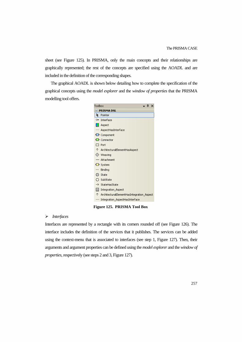
The PRISMA CASE
257
sheet (see Figure 125). In PRISMA, only the main concepts and their relationships are
graphically represented; the rest of the concepts are specified using the AOADL and are
included in the definition of the corresponding shapes.
The graphical AOADL is shown below detailing how to complete the specification of the
graphical concepts using the model explorer and the window of properties that the PRISMA
modelling tool offers.
Figure 125. PRISMA Tool Box
Interfaces
Interfaces are represented by a rectangle with its corners rounded off (see Figure 126). The
interface includes the definition of the services that it publishes. The services can be added
using the context-menu that is associated to interfaces (see step 1, Figure 127). Then, their
arguments and argument properties can be defined using the model explorer and the window of
properties, respectively (see steps 2 and 3, Figure 127).

PRISMA: Aspect-Oriented Software Architectures
258
Figure 126. Interface Shape
(1) Adding services to an interface
(2) Adding arguments to a service of an interface
(3) Filling the properties of an argument
Figure 127. Modelling Services of Interfaces
Aspects
Aspects are represented by a rectangle (see Figure 128). The aspect includes the definition of
attributes, services, valuations, preconditions, constraints, played_roles and transactions. They
can be added using the context-menu that is associated to each concept as in step 1 of Figure
127. Ten, their properties can be filled using the model explorer and the window of properties
as presented in steps 2 and 3 of Figure 127. Each aspect defines properties of a specific
concern. Each concern has a colour associated to it and, depending on the value of the aspect
concern, the aspect is painted in one colour or another. For example, the concern coordination
has the green colour associated to it (see Figure 128).

The PRISMA CASE
259
The importation of interfaces by an aspect is specified using the link AspectHasInterface,
which is provided by the tool box. This link automatically includes the interface services as
services of the aspect that is linked to the interface (see Figure 129).
Figure 128. Aspect Shape
Figure 129. Link Shape between Aspects and Interfaces

PRISMA: Aspect-Oriented Software Architectures
260
The aspect also includes the specification of its protocol. The protocol is modelled in a
graphical way. Protocols are specified by modelling a State Transition Diagram (STD) (see
Figure 130). The tool box provides a set of shapes to model the protocol of an aspect. These
shapes are states, substates, and transitions between these states (see Figure 125).
States define relevant states of the software system business logic. A state establishes the
services that can be executed when the aspect execution is placed in it. These states are
graphically characterized because they are painted in the same colour as the aspect (see Figure
130).
Substates help to define sequences of services that may or may not be transactional. They
are not states of the business logic of the software system and are characterized by always being
painted white (see Figure 130).
Transitions define the jump from one source state to another target state. Both the source
state and the target state can be states or substates (see Figure 130). The transition between
states has a service associated to it and can also have a condition, a played_role and a
transaction associated to it. These properties of the transition are filled using the window of
properties.
Figure 130. STD for modelling protocols
In addition to these generic shapes for modelling aspects and the concepts related to them,
two specialized shapes have been defined in the toolbox to define an aspect that has properties
that are different to the rest. The first one is the integration aspect, which is the mechanism for
integrating COTS in PRISMA software architectures (see section 10.2), it is graphically
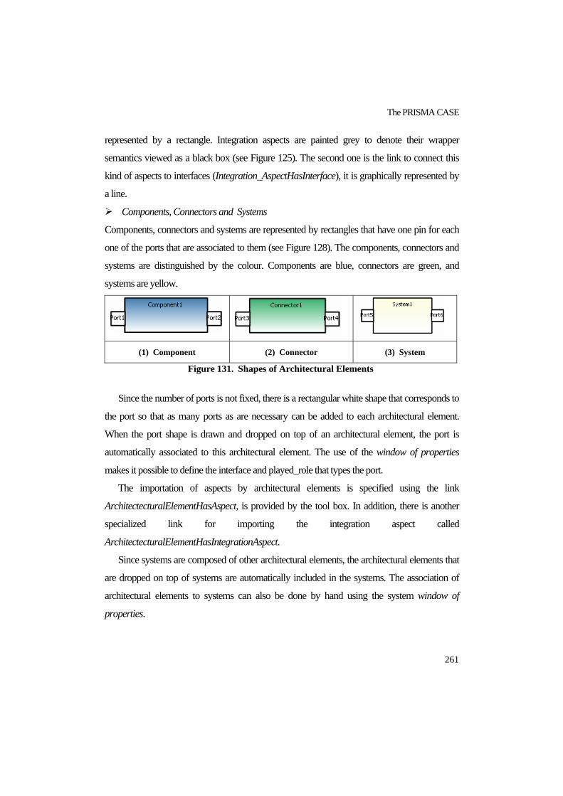
The PRISMA CASE
261
represented by a rectangle. Integration aspects are painted grey to denote their wrapper
semantics viewed as a black box (see Figure 125). The second one is the link to connect this
kind of aspects to interfaces (Integration_AspectHasInterface), it is graphically represented by
a line.
Components, Connectors and Systems
Components, connectors and systems are represented by rectangles that have one pin for each
one of the ports that are associated to them (see Figure 128). The components, connectors and
systems are distinguished by the colour. Components are blue, connectors are green, and
systems are yellow.
(1) Component (2) Connector (3) System
Figure 131. Shapes of Architectural Elements
Since the number of ports is not fixed, there is a rectangular white shape that corresponds to
the port so that as many ports as are necessary can be added to each architectural element.
When the port shape is drawn and dropped on top of an architectural element, the port is
automatically associated to this architectural element. The use of the window of properties
makes it possible to define the interface and played_role that types the port.
The importation of aspects by architectural elements is specified using the link
ArchitectecturalElementHasAspect, is provided by the tool box. In addition, there is another
specialized link for importing the integration aspect called
ArchitectecturalElementHasIntegrationAspect.
Since systems are composed of other architectural elements, the architectural elements that
are dropped on top of systems are automatically included in the systems. The association of
architectural elements to systems can also be done by hand using the system window of
properties.

PRISMA: Aspect-Oriented Software Architectures
262
Weavings
Weavings are represented by a diamond that joins the aspects that participate in the weaving
using incoming and outgoing arrows (see Figure 132). The arrows determine the direction in
which the weaving service is executed, i.e., the aspect service with the outgoing arrow is the
first to be executed, and the aspect service with the incoming arrow is the second to be
executed. The services that participate in the weaving as well as the operator are specified using
the window of properties. After specifying the operator, the operator is displayed in the center
of the diamond.
Figure 132. Weaving Shape
Attachments
Attachments are represented by a line that links a component port to a connector port (see
Figure 133). The properties of the attachment are specified using the window of properties.
Figure 133. Attachment Shape
Bindings
Bindings are represented by a dashed line that links an architectural element port to a system
port (see Figure 134). The properties of the binding are specified using the window of
properties.

The PRISMA CASE
263
Figure 134. Binding Shape
9.1.4.2. Verification of PRISMA Models The hardconstraints that have been defined in DSL tools are checked throughout the entire
modeling process. As a result, when the user tries to model something that violates a
hardcontstraint, the PRISMA modeling tool shows a prohibition sign.
The verification rules defined in DSL tools are checked each time that the model is saved.
The list of errors is displayed in the Error List window (see Figure 135).
Figure 135. Error List
Verification rules can also be checked whenever the user requires it. The PRISMA menu
offers the option of checking these rules in a complete or partial way (see Figure 136). The

PRISMA: Aspect-Oriented Software Architectures
264
complete way checks all the verification rules, while the partial way allows you to only check
one kind of PRISMA type. The options that are provided to check an architectural model in a
partial way are the following: interfaces, aspects, components, connectors, systems and
attachments. For example, if the user requests the Interface Verification, only the rules
associated to interfaces are checked. The advantage of this partial verification is that the user
can incrementally check the models and focus on the problems of a specific type of the model.
Figure 136. Verification Menu
In addition, the graphical modelling tool offers the mechanism of checking only one
element of the architectural model. This is possible by executing the option that appears in the
contextual menu that is associated to the element that the user wants to check. For example,
Figure 137 shows the contextual menu that only verifies the interface IMotionJoint.
Figure 137. Contextual Menu of an Element
9.2. MODEL COMPILER The PRISMA modelling tool also provides a set of templates to automatically generate the
code from the models that have been graphically modelled. The templates for generating the
AOADL specification and the C# code are already available. They can be extended to generate
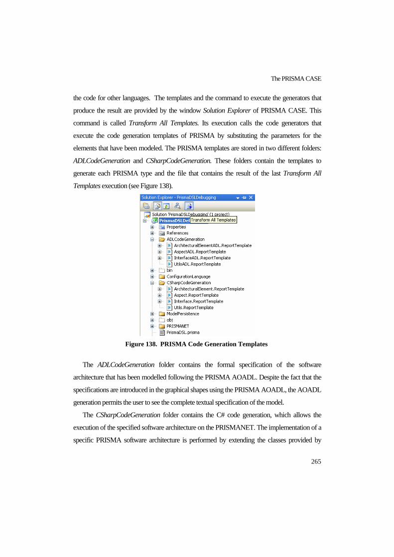
The PRISMA CASE
265
the code for other languages. The templates and the command to execute the generators that
produce the result are provided by the window Solution Explorer of PRISMA CASE. This
command is called Transform All Templates. Its execution calls the code generators that
execute the code generation templates of PRISMA by substituting the parameters for the
elements that have been modeled. The PRISMA templates are stored in two different folders:
ADLCodeGeneration and CSharpCodeGeneration. These folders contain the templates to
generate each PRISMA type and the file that contains the result of the last Transform All
Templates execution (see Figure 138).
Figure 138. PRISMA Code Generation Templates
The ADLCodeGeneration folder contains the formal specification of the software
architecture that has been modelled following the PRISMA AOADL. Despite the fact that the
specifications are introduced in the graphical shapes using the PRISMA AOADL, the AOADL
generation permits the user to see the complete textual specification of the model.
The CSharpCodeGeneration folder contains the C# code generation, which allows the
execution of the specified software architecture on the PRISMANET. The implementation of a
specific PRISMA software architecture is performed by extending the classes provided by

PRISMA: Aspect-Oriented Software Architectures
266
PRISMANET (see section 9.4.2). In order to develop these code generation templates, a set of
patterns has been identified and defined to generate the C# code for each one the PRISMA
concepts to be executed over PRISMANET. Next, the mappings of components and aspects
are presented in a simplified way by using the Actuator component and the FunctionActuator
aspect as an example. The complete list of patterns is presented in detail in [Cab05].
9.2.1. Components A component is implemented as a serializable C# class. This class is serializable in order to
enable mobility in future versions of PRISMA CASE. This class inherits from the
ComponentBase class of PRISMANET, which implements the component of the PRISMA
model. The component name is the same as the one in the PRISMA specification. The set of
ports and aspects that make up a component are included by invoking the constructors of the
port and aspect PRISMANET classes. Both classes implement the port and aspect elements of
the PRISMA model. For example, Figure 139 shows an initial specification of the component
Actuator and the C# code that the component pattern of the PRISMA CASE has automatically
generated from the specification.
Component Actuator
Integration Aspect Import RS232;
Ports
PCoord : IMotionJoint,
Played_Role RS232. INTMOVE;
End_Ports;
new(){RS232.begin();
destroy(){RS232.end();}
End_Component Actuator;

The PRISMA CASE
267
Figure 139. The generated C# code of the component Actuator
9.2.2. Aspects An aspect is implemented as a serializable C# class to enable mobility in the network. This
class inherits from the AspectBase class of PRISMANET, which implements the aspect
element of PRISMA model. The aspect name is the same as the name in the PRISMA
specification as well as the interface that it implements. Moreover, the kind of aspect is
specified in the implementation as defined in the specification.

PRISMA: Aspect-Oriented Software Architectures
268
The attributes of an aspect are implemented as variables of the C# class. The services
specified by a PRISMA aspect are implemented as methods of the aspect class. The
played_roles that make up an aspect are included by invoking the constructors of the
played_role PRISMANET class. The different states of the protocol are implemented as
internal variables that are checked inside of the service methods in which the priority of each
method is taken into account. The implementation of these methods follows a pattern that
implements the set of steps that must be executed in order to properly execute a PRISMA
service. These steps are the following:
1. Verification of Protocol: It must be verified that there is a valid transition for the
required service. This transition must depart from the state that the protocol is
executing at that moment.
2. Verification of Preconditions: It must be verified that every precondition associated
to the service is satisfied.
3. Selection of Valuations: The valuations that must be executed must be selected
depending whether or not their conditions are satisfied or not.
4. Execution of Valuations: The variables that represent the attributes or parameters
that must be updated due to the service method execution are modified.
5. Verification of Constraints: It must be verified that the constraints of the aspect are
satisfied by the new state of the aspect that has been reached due to the service method
execution. This verification is performed using exceptions as the verifications of
protocols and preconditions.
6. Execution of Service Sequences: There are services whose execution implies the
automatic execution of other services. In this case, these services are invoked.
7. Change of the protocol: If the method execution implies a change in the protocol
state, this change is performed by updating the state variable.

The PRISMA CASE
269
For example, Figure 140 shows the partial specification of the CProcessSuc coordination
Aspect (see the complete specification in C.3) and the C# code that the aspect pattern of the
PRISMA CASE has automatically generated from the specification.
Coordination Aspect CProcessSuc using ImotionJoint, IJoint, IRead,
IPosition
Attributes
Variables
validMovement: boolean, DEFAULT: false;
Services
begin();
in/out moveJoint(input NewSteps : integer, input Speed : integer);
in/out stop()
in/out moveOk(output Success : boolean; …
out newPosition(input NewSteps : integer)
end();
……
End_Aspect CProcessSuc;

PRISMA: Aspect-Oriented Software Architectures
270
Figure 140. The generated C# code of the aspect FunctionActuator

The PRISMA CASE
271
9.3. CONFIGURATION MODEL The PRISMA model that has been introduced in the Domain Model of DSL tools is a
metamodel, and the modelling tool (debugging solution) that has been developed from this
model provide us mechanisms to specify PRISMA aspect-oriented software architectures.
However, it is necessary to instantiate and to configure these architectures into specific ones
and provide the user mechanisms to do so. In order to cope with these needs, PRISMA CASE
automatically generates a domain specific graphical modelling tool to configure the software
architectures that have been defined using PRISMA CASE. As a result, the PRISMA
modelling tool is composed of two different tools: the modelling type tool and the modelling
configuration tool. The modelling configuration tool is generated from the models that have
been specified using the modelling type tool. As a result, the PRISMA graphical modelling is
compliant with the PRISMA AOADL, which is also divided into types and configuration (see
Figure 141).
A configuration modelling tool is generated for each PRISMA software architecture that is
modelled using the PRISMA modelling type tool. The configuration modelling tool is used to
develop specific software architectures using the PRISMA types defined in PRISMA type
modelling tools as modelling primitives.
The capacity to store all the information needed to automatically generate a domain-specific
tool permits the use of PRISMA architecture as a domain specific language in other model
specifications. It also permits the generation of the specification of the configuration language.
This information is generated using the code generators of DSL and is stored in the persistence
and configuration language folders of PRISMA type modelling tool (see Figure 142). The
information of these folders is the input for creating the new project for the domain-specific
PRISMA software architecture that has been defined.

PRISMA: Aspect-Oriented Software Architectures
272
(1) PRISMA Type Modelling Tool
(2) PRISMA Configuration Modelling Tool
Figure 141. Generation and Execution of the PRISMA Modelling
Configuration Tool

The PRISMA CASE
273
Figure 142. Model Persistence and Configuration Language Information
The automatic generation of a tool for modelling configurations of a PRISMA software
architectures is performed by executing the PRISMA Model Configuration option of the menu
PRISMA after the transformation of all templates has been done (see step 1 in Figure 141).
Next, a new project is automatically created and can be used as a configuration modelling tool.
Step 2 of Figure 141 shows how the Actuator and Sensor types defined in step 1, Figure 141
appear in the tool box of the Configuration Modelling Tool as shapes for modelling. It shows
how these types have been dragged and dropped on the drawing sheet generating two
instances. As a result, the base joint is modelled by defining its actuator and sensor.
In addition, the configuration modelling tool provides a command to transform its templates
to obtain the AOADL specification that corresponds to the configuration that has been defined
using the tool. Finally, this tool permits the execution of the generated code. In order to do this,
the PRISMA menu offers the option PRISMANET, which executes the middleware
PRISMANET and instantiates the defined configuration. As a result of this execution, a

PRISMA: Aspect-Oriented Software Architectures
274
generic GUI is launched to interact with the architecture by invoking its services and checking
the value of its attributes (see Figure 143). The main purpose of the generic GUI is to assist the
user in checking the behaviour of the architecture without having to worry about aesthetic
details and without forcing the user to define a GUI in order to obtain a result.
Figure 143. Generic GUI of PRISMA Applications
However, it is important to mention that the use of this interface is not mandatory. In other
words, if the users prefer to define their own specialized forms, they can do so. They only have
to integrate them with the architecture by using the presentation aspect that the PRISMA
modelling tool offers. Users must define the services to interact with the defined forms inside
the presentation aspect and to synchronize them with the rest of aspects that belong to the same
architectural element by means of weavings. The forms are included in the project folder so
that the GUI of the user is executed instead of the generic interface that PRISMA CASE
provides by default.

The PRISMA CASE
275
9.4. PRISMANET PRISMANET implements the PRISMA model by extending the .NET technology with the
incorporation of aspects. PRISMANET is the platform-dependent model of PRISMA, which
permits PRISMA software architectures to be developed and executed on the .NET platform.
PRISMANET offers extra functionalities and characteristics that .NET does not directly
provide. It allows for the execution of aspects, the concurrent execution of aspects and
architectural elements, the loading of components, the creation of execution threads, the
management of the local components, etc.
Even though PRISMANET has only been used for software architectures that are locally
executed, due to the distributed nature of software, the distributed execution of software
architectures will be supported by PRISMANET in the near future. To completely reuse
PRISMANET when it will be extended to support distribution and mobility capabilities,
aspects and components have been developed so that they can be executed and can
communicate with each other in both a local and distributed way.
This section presents how the PRISMA model, its execution model, and its aspect-oriented
properties have been implemented in the .NET technology.
9.4.1. PRISMANET Architecture The .NET framework consists of several layers at different levels of abstraction. Not all the
technologies that support AOP in the .NET platform are applied to the same layer of the .NET
framework. Figure 144 shows the different layers that .NET framework consists of and also
classifies the AOP .NET technologies according to the layers they have been applied to. These
technologies are analyzed in section 3.3.3.

PRISMA: Aspect-Oriented Software Architectures
276
Figure 144. Layer classification of technologies that support AOP in .NET
framework
The AOP .NET technologies can be classified into three kinds. These kinds of AOP .NET
technologies are defined by the way in which the base code and the aspect code are weaved
and by the layer in which this weaving process is performed [Jac04]. These three kinds of AOP
.NET technologies are the following:
AOP .NET technologies applied to the Common Language Runtime (CLR) layer:
This kind of AOP .NET technology extends the CLR by adding new mechanisms to
perform weavings (see Figure 144). The advantage of this kind of AOP .NET technology
is that its approach is independent of the programming language. However, one of its
inconveniences is that the pointcuts are limited by the mechanisms used for weaving the
aspect code and the base code at the CLR level. Moreover, since the CLR is modified, the
standard debugging tools cannot be used.
AOP .NET technologies applied to the MicroSoft Intermediate Language (MSIL)
layer: This kind of AOP .NET technology modifies the MSIL to weave the base code and
the aspect code (see Figure 144). Most of these technologies modify the MSIL of the
assemblies to intercept the methods at runtime, thereby executing aspects. The advantage
of this kind of AOP .NET technology is that its approach is independent of the

The PRISMA CASE
277
programming language. However, the standard debugging tools cannot be used as in the
previous kind, and it does not allow for the dynamic definition of weavings.
AOP .NET technologies applied to the Common Language System/Common Type
System (CLS/CTS) layer: This kind of AOP .NET technology extends the CLS/CTS to
weave the base and aspect code at compilation time (see Figure 144). One of the main
inconveniences of these technologies is their dependence on the programming language.
Another inconvenience is the need to adapt compilers of the programming languages that
this kind of technology extends in order to adjust them to the evolution of these
programming languages.
These three kinds of AOP Technologies share an additional inconvenience. They depend
on the .NET platform. As a result, they must be modified in order to be compatible with future
versions of the .NET platform. In order to avoid these inconveniences, PRISMANET has been
applied to a higher layer of abstraction without extending the development platform.
PRISMANET implementation is localized in a new layer that sits over the .NET framework
(see Figure 144). This can be done because PRISMA is a technology-independent model.
PRISMANET implementation has been carried out in C# language using the standard
techniques and mechanisms that the .NET framework provides, that is, without extending the
development platform. As a result, PRISMANET does not have to be updated to the new
versions of the CLR, MSIL and so forth, and it can be executed in the .NET platform without
having to do anything else other than starting the execution of the middleware. The most
important .NET technology mechanisms [Rob03] that have been used are: delegates,
reflection, serialization and .NET Remoting [MIC05].
The PRISMANET architecture is constituted by four main modules (see Figure 145):
The PRISMA Execution Model: This module implements the basic functionality of the
PRISMA types. This implementation is divided into two modules that contain the classes
that implement this functionality: the Types and Communications modules. The Types
module implements aspects and architectural elements, and the Communications module
implements attachments and bindings. As a result, the implementation of the PRISMA
application is achieved by extending these classes.

PRISMA: Aspect-Oriented Software Architectures
278
Figure 145. PRISMANET Middleware
Memory Persistence: This module provides services to manage and maintain the
instances of architectural elements that are stored in the main memory during their
execution. The middleware manages the instances that are locally executed. Some of these
services are the loading of architectural elements instances, the creation of execution
threads, and the management of architectural element lists.
Transaction Manager: This module provides services to suitably execute transactions.
Log: This module logs every operation that it is performed by the middleware in order to
register the execution history of software architectures.
PRISMANET has to be running on all PCs where a PRISMA application is being
executed. The middleware manages the architectural elements instances that are being
executed in the PC, providing the necessary services to its instances. As a result, there are two
kinds of communications concerning PRISMANET and the applications that run on it:
Communication among PRISMANET and the architectural element instances to ask for
maintenance services.
Communication among different PRISMA components as a result of the execution of the
application.

The PRISMA CASE
279
9.4.2. PRISMA model implementation Each concept defined in the PRISMA model has been implemented in the module PRISMA
Execution Model of PRISMANET. The implementation has been carried out preserving the
following features:
The implementation has to be as close as possible to the PRISMA model in order to
facilitate automatic code generation. Therefore, PRISMANET is the PRISMA model that
is dependent on the .NET technology, i.e., it is the platform-dependent model of PRISMA.
The execution of attachments, connectors and components must be concurrent in order to
be compliant with the PRISMA Model Formalization (see section 6.2). In addition, the
concurrency among the different aspects that make up a component must be preserved.
The Types and Communication modules that compose the module PRISMA Execution
Model have been grouped by namespaces of .NET in order to clearly identify the
implementation of each one of the PRISMA types (see Figure 146).
Figure 146. Namespaces of the module PRISMA Execution Model

PRISMA: Aspect-Oriented Software Architectures
280
9.4.2.1. Asynchronous executions There are mechanisms that the .NET platform offers to support asynchronous invocations of
services such as the classes Delegate and AsyncResult. However, these mechanisms are
managed by the .NET platform and they cannot be customized for the specific needs of a new
execution model such as the PRISMA model. Therefore, a new class AsyncResult has been
created to implement the asynchronous invocations of the PRISMA model by hiding the
specific details of the .NET platform, and by dealing with the PRISMA peculiarities such as the
management of requests, the service execution based on priorities, the request resendings to
other architectural elements, etc.
The class AsyncResult is the structure that allows the client of a service to verify whether or
not its request has been successfully executed once the service execution has finished. If it has
been successfully executed, the results can be obtained. For this reason, in PRISMA, every
service provided by a server that can be asynchronously executed must return an AsyncResult
structure.
Execution of an asynchronous invocation
PRISMA servers have a mechanism that stores the requests that they receive while they are
executing another request. This mechanism consists of creating a delegate and an AsyncResult
structure for each request that the server receives and storing them to be processed afterwards.
Then, the server sends the reference of the AsyncResult structure that the server has created to
the client. Thus, the client does not have to wait for the result and can continue its execution.
When the server processes the client request, it executes the delegate associated to this
request, i.e., it executes the request service and stores the results in the AsyncResult structure
associated to the request. Since the client has the reference of the AsyncResult structure, this
structure can be queried by the client whenever necessary. The client checks the request
execution as well as the results that have been obtained from it.
This execution model together with the AsyncResult structure allows for the asynchronous
execution of the requests of PRISMA services.

The PRISMA CASE
281
9.4.2.2. Aspects The aspect type has been implemented as a C# class called AspectBase of the PRISMANET
(see Figure 147). This class stores the name of the aspect and its thread reference as well as
other properties. The AspectBase class has the references of the component and the middleware
that it belongs to in order to request services from them. This class offers services to start the
execution of the aspect thread, to stop the execution of the aspect thread, and to abort the
execution of the aspect thread.
A played_role has been implemented as a C# class called PlayedRoleClass (see Figure
147), which stores information about the services of the played_role and their priorities. The
played_roles of an aspect are stored in the class PlayedRoleCollection that the aspect is related
to (see Figure 147).
The class AspectBase also contains a priority queue to deal with the service requests that
arrive to the aspect in the order specified by the protocol (see Figure 147).
Figure 147. Main classes of the namespace Aspects of PRISMANET4
4 The set of classes that appear in the figure have been automatically generated from the source code of PRISMANET using the Sparx tool http://www.sparxsystems.com/
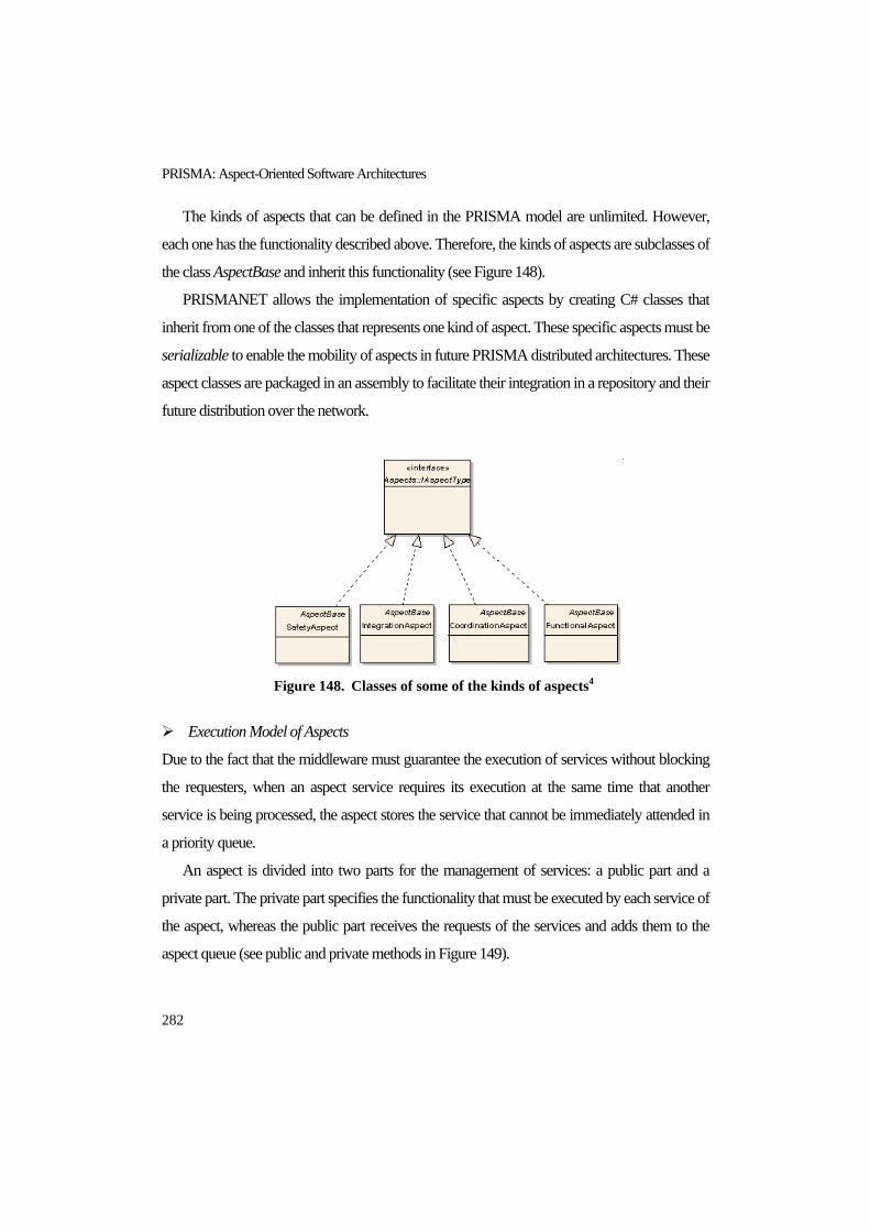
PRISMA: Aspect-Oriented Software Architectures
282
The kinds of aspects that can be defined in the PRISMA model are unlimited. However,
each one has the functionality described above. Therefore, the kinds of aspects are subclasses of
the class AspectBase and inherit this functionality (see Figure 148).
PRISMANET allows the implementation of specific aspects by creating C# classes that
inherit from one of the classes that represents one kind of aspect. These specific aspects must be
serializable to enable the mobility of aspects in future PRISMA distributed architectures. These
aspect classes are packaged in an assembly to facilitate their integration in a repository and their
future distribution over the network.
Figure 148. Classes of some of the kinds of aspects4
Execution Model of Aspects
Due to the fact that the middleware must guarantee the execution of services without blocking
the requesters, when an aspect service requires its execution at the same time that another
service is being processed, the aspect stores the service that cannot be immediately attended in
a priority queue.
An aspect is divided into two parts for the management of services: a public part and a
private part. The private part specifies the functionality that must be executed by each service of
the aspect, whereas the public part receives the requests of the services and adds them to the
aspect queue (see public and private methods in Figure 149).

The PRISMA CASE
283
Figure 149. Execution Model of an Aspect
The execution of an aspect service is performed as described below:
<<When the execution of a service is requested from an aspect, the request comes from the
public method of the service (see step 1, Figure 149). The request is added to the queue of the
aspect with all the needed information to execute it (see step 2, Figure 149). To prevent the
requester that is waiting for the result from being blocked, the reference of the AsyncResult
structure is sent to the requester as explained in section 9.4.2.1 (see step 3, Figure 149).
Requests are then extracted from the queue in order to be executed taking into account the
priorities of the services and whether they can be executed in the state that the aspect is in that
moment. The requests are extracted from the queue following a FIFO policy ordered by the
service priority. As a result, the requests with higher priority are executed first and the requests
with the same priority are ordered using the standard FIFO policy (see step 4, Figure 149). It
must also be taken into account that sometimes the first request of the queue cannot be
executed because its execution is not allowed by the state of the protocol. In this case, the
request is not extracted from the queue, and its number of execution attempts is increased and
PRISMA: Aspect-Oriented Software Architectures
284
the next request in the queue is executed. After its execution, the execution of the first request
of the queue is tried again because the state of the protocol could have been changed by the
previous execution. In this way, the aspect thread gives the previously failed services the
chance of being executed. However, if a service request fails the maximum of number of
execution attempts that has been determined by PRISMANET, the request is extracted from
the queue and generates an exception that is sent to the requester. If the first request of the
queue can be processed, the functionality of its corresponding private method is executed and
the result of the execution is stored in its AsyncResult structure (see step 5, Figure 149). Finally,
this structure will be queried by the requester to obtain the results of the service execution. >>
It is important to emphasize that while the aspect thread is executing a private method the
public method can concurrently receive new requests and can add them to the queue. It must
also be emphasized that to stop the execution of an aspect appropriately, three steps must be
performed: 1. reject new requests from the public part; 2. execute the requests that are already
stored in the queue until it is empty, and 3. stop the aspect thread.
9.4.2.3. Simple Architectural Elements: Components and Connectors The architectural element type has been implemented as a C# class of PRISMANET called
ComponentBase. This class stores the name of the architectural element, its own thread and its
middleware references, the dynamic list of aspects, the dynamic list of weavings, and the
references to the ports to be able to receive and request services. In addition, the
ComponentBase class offers services to initiate the architectural element thread execution, to
stop the architectural thread execution, to abort the architectural element thread execution, to
query if an aspect of the architectural element is weaved with another aspect, and to add aspects
and weavings from an architectural element. Finally, it is important to emphasize that the
architectural element contains a queue that guarantees the execution of services without
blocking the requesters by storing the service requests that cannot be immediately attended to.

The PRISMA CASE
285
Figure 150. Main classes of the namespace Components of PRISMANET4
Connectors have been implemented as components because the functionality that they must
provide in the middleware is the same. The difference between components and connectors is
that connectors implement the interface IConnector and components implement the interface
IComponent. However, the interface IConnector inherits the properties of IComponent, but it
does not extend its properties. In fact, this interface is only used as an identification mechanism
between components and connectors.
As a result, PRISMANET allows the implementation of a specific architectural element by
creating a C# class that inherits from the ComponentBase class. It is important to keep in mind
that architectural elements must be serializable in order to enable their mobility in future
PRISMA distributed architectures.
Ports
The port type has been implemented as a C# class called Port. The ports of an architectural
element are classified into input (inPorts) and output (outPorts) ports. As a result, inPorts and
outPorts inherit their properties from the class Port. This class stores the name of the port, the
references to the interface and the played_role that is associated to it, and the list of attachments
that are connected to it (see Figure 151).

PRISMA: Aspect-Oriented Software Architectures
286
Figure 151. Main classes of the namespace Ports of PRISMANET4
InPorts publish the services that architectural elements provide. An InPort publishes an
interface that is implemented by one of the architectural element aspects. In addition, an InPort
is in charge of adding the received service requests to the architectural element queue.
OutPorts are in charge of providing mechanisms to send service requests to other
architectural elements. An OutPort only permits the sending of those service requests that
belong to the OutPort interface.
Ports offer reflection mechanisms to be dynamically queried, and thereby to dynamically
get the list of interfaces that are associated to the architectural element ports making dynamic
communications feasible. In addition, the implementation of ports also allows the isolation of
aspect services and the services that architectural elements publish through their ports. Since the
aspect that implements the port interface is known, ports have a set of delegates that point to
each of the aspect services that must be executed when an interface service is requested. As a
result, when a service interface is requested, its corresponding delegate is stored in the
architectural element queue.

The PRISMA CASE
287
Weavings
An architectural element contains a weaving manager that checks whether or not a service has
associated weavings. If so, the weaving manager executes them synchronously, and, if not, the
service is resent to the corresponding aspect.
There are no previous .NET works that implement weavings at the source code level and
that could dynamically perform weavings (see Figure 144). From the different strategies of
implementing weavings, the static code injection strategy provides the best performance, and
the code interception strategy is the most flexible. Therefore, in order to balance the advantages
of performance and flexibility, weavings have been implemented as a dynamic linked list with
three levels of depth. This list is part of the weaving manager of the architectural element and
contains the weavings that belong to the architectural element. Thus, this weaving
implementation facilitates the management of the weavings.
The dynamic list is implemented by the C# class WeavingsCollection (see Figure 152).
Each element of this dynamic list is an instance of the C# class AspectTypeNode, which
contains the aspect type and another dynamic list called weavingAspectList. Each element of
the WeavingAspectList is an instance of the C# class WeavingNode. This class stores the
service name, which triggers the weaving execution as well as a delegate of this service for its
dynamic invocation. It also stores three more lists, each of which belongs to a weaving operator
(after, before, instead) and contains instances of the C# class WeavingMethod. This class stores
the delegate, which points to the method that must be executed as a result of the weaving
(advice service). It also stores the method that has triggered the weaving execution (pointcut
service), and the weaving operator (after, before, instead, afterif, beforeif, insteadif) (see Figure
152).
The weaving manager executes weavings. This weaving execution consists of searching
the methods that are involved in the weaving by going through the lists beforeList, afterList and
insteadList. The execution of the corresponding delegates must be performed in the correct
order. To preserve this order, the first services in being executed are the advice services of the
weaving that are stored in WeavingNode.beforeList, and then their pointcut services are
executed. The second services in being executed are the advice services of the weaving that are

PRISMA: Aspect-Oriented Software Architectures
288
stored in WeavingNode.insteadList. Finally, the third services in being executed are the pointcut
services of the weaving that are stored in the WeavingNode.afterList., and then their advice
services are executed.
Figure 152. Dynamic List of Weavings4
Execution Model of Architectural Elements
An architectural element is composed of input (InPorts) and output (OutPorts) ports, a queue
that temporally stores the services that will be processed by the thread of the architectural
element, a weaving manager, and a set of aspects that are concurrently executed.
Figure 153. The execution model of an architectural element

The PRISMA CASE
289
Taking into account the properties of the elements that architectural elements are composed
of, the execution of a service that is requested from an architectural element performs the
following process:
<<When the execution of a service is requested from an architectural element, the request
comes from the port that publishes the service (see step 1, Figure 153). The port sends the
request to the queue of the architectural element (see step 2, Figure 153). Due to the fact that
several ports can try to add requests to the queue at the same time, the queue is protected from
concurrent access using monitors. As a result, only one port can add a request to the queue at
the same time.
Once the architectural element thread extracts the requested service from the queue, the
architectural element checks if the requested service has weavings associated to it (see step 3,
Figure 153). If the service does not have any weavings, its delegate is asynchronously executed
so that the architectural element can process another request from the queue. The delegate
execution consists of adding the service to the queue of the corresponding aspect. Then, the
aspect thread executes the service (see step 5, Figure 153). However, if the service has
weavings associated to it, before executing step 5, the service is sent to the weaving manager
(see step 4, Figure 153). The manager processes weavings by creating its own thread and
freeing the component from this task. >>
With regard to starting or stopping an architectural element, when the middleware calls the
start service of an architectural element, the architectural element calls the startAspect service
of each one of its aspects. When the middleware calls the stop or abort services of an
architectural element, the threads of its aspects must also be stopped or aborted. To stop an
architectural element in a secure way, a set of operations must be performed to achieve a secure
state that will permit the start of the architectural element execution in the future. An
architectural element is in a secure state when it does not have requests in its aspect queues and
there are no executing services. These operations consist of rejecting new services in their
queues and processing all the services that were already stored in the queue before the stop
execution.
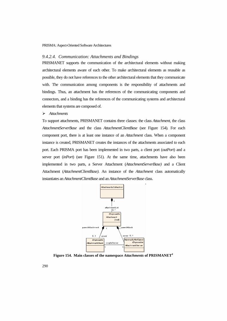
PRISMA: Aspect-Oriented Software Architectures
290
9.4.2.4. Communication: Attachments and Bindings PRISMANET supports the communication of the architectural elements without making
architectural elements aware of each other. To make architectural elements as reusable as
possible, they do not have references to the other architectural elements that they communicate
with. The communication among components is the responsibility of attachments and
bindings. Thus, an attachment has the references of the communicating components and
connectors, and a binding has the references of the communicating systems and architectural
elements that systems are composed of.
Attachments
To support attachments, PRISMANET contains three classes: the class Attachment, the class
AttachmentServerBase and the class AttachmentClientBase (see Figure 154). For each
component port, there is at least one instance of an Attachment class. When a component
instance is created, PRISMANET creates the instances of the attachments associated to each
port. Each PRISMA port has been implemented in two parts, a client port (outPort) and a
server port (inPort) (see Figure 151). At the same time, attachments have also been
implemented in two parts, a Server Attachment (AttachmentServerBase) and a Client
Attachment (AttachmentClientBase). An instance of the Attachment class automatically
instantiates an AttachmentClientBase and an AttachmentServerBase class.
Figure 154. Main classes of the namespace Attachments of PRISMANET4

The PRISMA CASE
291
Figure 155 shows how a component and a connector are connected to each other through
an attachment. The ports of both the component and the connector have an attachment
associated to them. Specifically, the component port has the attachment X associated to it and
the connector port has the attachment Y associated to it. The AttachmentClientBase of the
attachment X listens to the component outPort (see step 1, Figure 155 ) and resends services to
the AttachmentServerBase of the connector attachment Y (see step 2, Figure 155 ). Then,
AttachmentServerBase of the attachment Y resends services to the connector inPort in order to
be executed by it (see step 3, Figure 155 ). The communication in the inverse direction is
performed in the same way. The AttachmentClientBase of the attachment Y listens to the
connector outPort (see step 4, Figure 155 ) and resends the services to the
AttachmentServerBase of the component attachment X (see step 5, Figure 155 ). Finally, the
AttachmentServerBase of the attachment X resends the services to the component import in
order to be executed (see step 6, Figure 155 ).
Figure 155. The execution model of an attachment
An AttachmentClientBase instance has a thread that listens to a specific outPort of an
architectural element instance. When the AttachmentClientBase instance detects that there is a
request in the outPort, the request is resent to the instance of an AttachmentServerBase. Thus,
the AttachmentClientBase instance has a reference or a proxy of the AttachmentServerBase.
The AttachmentServerBase is a MarshalByRefObject class of the .NET Remoting framework.
This is necessary to create a proxy of the instance to allow the AttachmentClientBase instance
to access to it remotely in a future version of PRISMANET.

PRISMA: Aspect-Oriented Software Architectures
292
All elements that are involved in an attachment are related to each other in one way or
another. As a result, it is possible to define an invocation cycle that involves all the elements
that participate in the attachment. When an element that participates in this cycle receives a
request, it must process the established actions and propagate the invocation to the next element
in the cycle. The execution order of the cycle, taking into account the attachment presented in
Figure 155, is the following: Attachment: InterfaceX AttachmentClientBase:InterfaceYClient
AttachmentServerBase:InterfaceYServer Attachment:InterfaceY
AttachmentClientBase:ClientInterfaceX
AttachmentServerBase:InterfaceXServer Attachment:InterfaceX
This cycle determines the execution model of an attachment. The invocation cycle starts
and stops at the same point to detect when the communication has been finished.
The attachments are solely responsible for the communication of the components and
connectors. PRISMANET only participates in the creation of attachment instances between its
component and connectors instances. To store the list of attachments in its site, the middleware
has an AttachmentCollection class (see Figure 154). Since middleware does not manage the
communication process, its implementation is simplified and the independence and
maintainability of attachments are increased.
Bindings
Bindings connect system ports and ports of the architectural elements that the system is
composed of. Bindings have been designed in a way similar to attachments. Bindings consist
of two parts: the part of the system (SystemBinding) and the part of the architectural element
that the system is composed of (ComponentBinding) (see Figure 156). The difference between
attachments and bindings is introduced by a binding manager, which is called SystemBinding.
There is only one SystemBinding for each system, i.e., there is not a SystemBinding for each
system port as occurs in attachments. As a result, SystemBinding contains the references of
every binding connected to the system ports. In addition, the SystemBinding does not have a
server part and a client part as attachments have; it only has a server part., which is called

The PRISMA CASE
293
SystemBindingServer (see Figure 156). The SystemBindingServer is in charge of localizing the
system’s architectural elements that are connected to bindings and resending them the requests
that arrive to the bindings. However, the part of the binding related to the system’s architectural
element (ComponentBinding) is implemented in the same way as attachments. The
ComponentBinding has a ComponentBindingClient that listens to its outPort and resends
services to the SystemBindingServer of the system as well as a ComponentBindingServer that
receives the request through its inPort (see Figure 156).
Figure 156. Main classes of the namespace Bindings of PRISMANET4
When the SystemBindingServer detects that there is a request in a system inPort, the request
is added to the system queue (see step 1, Figure 157). Then, when the request is extracted from
the queue by the SystemBinding (see step 2, Figure 157), and it resends the request to the
correspondent ComponentBidingServer. When the ComponentBindingServer receives the
request (see step 4, Figure 157), it is sent to the InPort (see step 4, Figure 157), and it is

PRISMA: Aspect-Oriented Software Architectures
294
processed by the architectural element. On the other hand, when an internal architectural
element sends a request through its Outport (see step 5, Figure 157), since its
componentBindingClient is listening to the OutPort all the time, it realizes that there is a request
and it resends the request to the SystemBindingServer (see step 6, Figure 157). Finally, the
SystemBindingServer sends the request through the corresponding outPort of the system (see
step 7, Figure 157).
Figure 157. The execution model of bindings
9.4.2.5. Complex Architectural Elements: Systems Systems are been implemented as a specialized class of ComponentBase called SystemBase.
This class inherits the properties of components and defines a set of services that characterize
the system. These services allow components, connectors, attachments and bindings to be
added to the system. They are grouped by the interface ISystem, which is implemented by the
class SystemBase (see Figure 158).
The class SystemBase is in charge of maintaining the list of architectural elements,
attachments and bindings that the system is composed of. In addition, SystemBase invokes the
services needed by the middleware to start the execution of those elements that the system is
composed of.

The PRISMA CASE
295
Due to the fact that a system is composed of a set of elements, it overwrites the start and
stop services of the ComponentBase class by extending their behaviour to start the execution of
these elements.
Figure 158. Main classes of the namespace Systems of PRISMANET4
9.4.3. Memory Persistence The class MiddlewareSystem implements the functionality that is dependent on the .NET
technology (see Figure 159). It provides a wide variety of services to the PRISMA architectural
elements so that they are properly maintained. This maintenance is managed by
MiddlewareSystem and its different functionalities have been structured in different related
classes. These classes are the class ElementManagementServices, which manages the
architectural elements and connections, and the class TypeManagementService, which
manages types (see Figure 159).
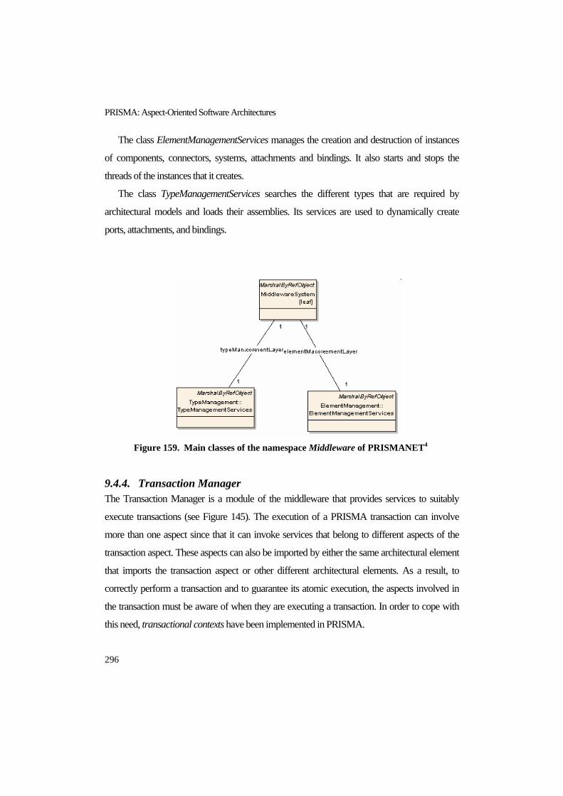
PRISMA: Aspect-Oriented Software Architectures
296
The class ElementManagementServices manages the creation and destruction of instances
of components, connectors, systems, attachments and bindings. It also starts and stops the
threads of the instances that it creates.
The class TypeManagementServices searches the different types that are required by
architectural models and loads their assemblies. Its services are used to dynamically create
ports, attachments, and bindings.
Figure 159. Main classes of the namespace Middleware of PRISMANET4
9.4.4. Transaction Manager The Transaction Manager is a module of the middleware that provides services to suitably
execute transactions (see Figure 145). The execution of a PRISMA transaction can involve
more than one aspect since that it can invoke services that belong to different aspects of the
transaction aspect. These aspects can also be imported by either the same architectural element
that imports the transaction aspect or other different architectural elements. As a result, to
correctly perform a transaction and to guarantee its atomic execution, the aspects involved in
the transaction must be aware of when they are executing a transaction. In order to cope with
this need, transactional contexts have been implemented in PRISMA.

The PRISMA CASE
297
A transactional context defines the boundaries of a transaction. In PRISMA, transactional
contexts notify aspects if they are executing a service that is involved in a transaction.
Therefore, the aspect is blocked by the transactional context and it only executes requests that
come from this transactional context until the transaction finishes. This notification is
performed by adding the transactional context name to the service request that is temporarily
stored in the queue of the aspect.
The class TransactionManager is responsible for the transactional context management.
When the execution of a transaction is started, the middleware is notified and a new entry to the
TransactionalContext list of the Transaction Manager is added (see Figure 160).
TransactionManager stores an incremental sequence number, a reference to the
MiddlewareSystem, the TransactionalContext list and the reference of the TransactionLog file.
Figure 160. Main classes of the namespace TransactioManager of
PRISMANET4
The class TransactionalContext has a context identifier and maintains the information
related to the transaction failures. It stores which is the state of the transaction and when it
finishes.

PRISMA: Aspect-Oriented Software Architectures
298
It is important to take into account that there can be transactions that have other nested
transactions [Mos87]. A transactional hierarchy is created, which can be represented as a tree
whose root is the initial transaction. Thus, each transaction that is involved in a nested
transaction has an associated nesting level number, where 0 is the nesting level number of the
root, and where the highest nesting level number is the most nested transaction. The class
TransactionalContext is in charge of storing the nesting level number of each transaction.
When a transaction has nested transactions and one of them fails, every action performed
by the nested transaction will be undone unless the transaction can treat the failure. The commit
of a nested transaction is considered to be partial commit until it has beenconfirmed that every
transaction that includes the nested transaction does not fail. In fact, the only commit that is not
partial in a hierarchical transaction is the commit of the root transaction. As a result, a
transactional context has the following possible states (see the relationship state in Figure 160):
ACTIVE : The transaction is being executed
PRECOMMITTED : The transaction has finished. However, since it belongs to a
transactional hierarchy, it must wait for the end of all the transactions of the hierarchy in
order to confirm the commit or execute a rollback..
PREROLLBACK : The transaction has finished. However, since it belongs to a
transactional hierarchy, it must wait for the end of the root transaction because it
establishes the execution order of the transitions that it nests.
COMMITTED : The transaction has finished successfully.
ROLLBACKED : The transaction has finished due to a failure.
There is a TransactionLog file for each transactional context, in which all the actions of the
transactional process are recorded. Each entry of the TransactionLog has a sequence number, a
reference to the previous sequence number, and the inverse action of the action that has been
performed. As a result, each transactional context has a TransactionLog file that is executed by
the middleware when a transaction fails. This file execution reestablishes the state of the
architecture that there was after the transaction execution.

The PRISMA CASE
299
Figure 161. Main classes of the TransactioLog of PRISMANET4
9.4.5. Log The Log is a module of PRISMANET that logs every operation that is performed by the
middleware in order to register the execution history of software architectures (see Figure 145).
It is important to emphasize that this log is different from the TransactionLog; its functionality
consists of recording the actions that are executed by the middleware like as if it were a
blackboard. The only purpose of this log is to provide information about the software
architecture execution. This log is shown by PRISMANET during its execution and provides
the updated information at runtime (see Figure 162 ).
Figure 162. Execution of a PRISMANET Log

PRISMA: Aspect-Oriented Software Architectures
300
9.5. CONCLUSIONS PRISMA CASE has been presented in this chapter. PRISMA CASE is a framework that
provides complete support for developing software systems following the PRISMA approach.
It is composed of a set of tools that is suitably integrated to provide a unique framework that
gives support to the user throughout the software life cycle. This integration also provides
traceability during the different stages of the software life cycle and facilitates the maintenance
of the developed software products.
This set of tools includes the PRISMA Types Graphical Modelling Tool with its code
generation patterns, the PRISMA Configuration Graphical Modelling Tool with its code
generation patterns, the generic Graphical User Interface for PRISMA applications, and the
middleware PRISMANET.
The PRISMA Types and Configuration Graphical Modelling Tools give support to the
development of PRISMA software architectures following the MDD approach and using the
PRISMA AOADL in a graphical way. As a result, PRISMA offers mechanisms to develop
software architectures in a more intuitive and friendly way and mechanisms to verify their
models. In addition, the code generation patterns that PRISMA modelling tools offer allow
automatically generate executable C# code on PRISMANET from the specified graphical
models. Thus, PRISMA CASE deals with the traceability between software architectures and
implementation and reduces the time and cost invested in the development and maintenance
processes.
PRISMA CASE provides a generic Graphical User Interface to execute software
architectures. This is an important advantage because it is a simple way of validating that
software architectures provide the behaviour expected by the user without having to develop a
customized graphical user interface.
RISMANET is an innovative middleware based on the PRISMA model, which allows the
implementation of complex, aspect-oriented and component-based software systems using C#
language. PRISMANET has been developed with C# language using the standard techniques
that the framework provides, that is, without extending the development platform. As a result,
PRISMANET can be executed on every computer that has the .NET framework installed.
The PRISMA CASE
301
PRISMANET offers extra functionalities for the .NET platform. It allows the execution of
aspects, the configuration of software architectures (local and distributed), the communication
among different components that are unaware of each other, etc. PRISMANET has also been
tested in case studies such as the TeachMover tele-operated robot, banking systems, electronic
auctions, etc.
This chapter demonstrates that all the tools and mechanisms that PRISMA CASE provides
make PRISMA a mature and well-supported approach for developing large and complex
software systems.
The work related to the PRISMA model has produced a set of results that is published in
the following publications:
Jennifer Pérez, Elena Navarro, Patricio Letelier, Isidro Ramos, A Modelling Proposal for
Aspect-Oriented Software Architectures, 13th Annual IEEE International Conference and
Workshop on the Engineering of Computer Based Systems (ECBS), IEEE Computer
Society , pp.32-41, ISBN: 0-7695-2546-6, Potsdam, Germany (Berlin metropolitan area),
March 27th-30th, 2006.
Jennifer Pérez, Elena Navarro, Patricio Letelier, Isidro Ramos, Graphical Modelling for
Aspect Oriented SA, 21st Annual ACM Symposium on Applied Computing, ACM, pp.
1597-1598, ISBN: 1-59593-108-2, Dijon, France, April 23 -27, 2006. (short paper)
Jennifer Pérez, Nour Ali, Cristobal Costa, José Á. Carsí, Isidro Ramos, Executing Aspect-
Oriented Component-Based Software Architectures on .NET Technology, 3rd
International Conference on .NET Technologies, pp. 97-108, Pilsen, Czech Republic,
May-June 2005.
Cristóbal Costa, Jennifer Pérez, Nour Ali, Jose Angel Carsí, Isidro Ramos, PRISMANET
middleware: Support to the Dynamic Evolution of Aspect-Oriented Software
Architectures, X Conference on Software Engineering and Databases (JISBD), pp. 27-34,
ISBN: 84-9732-434-X, Granada, September, 2005. (In Spanish)

PRISMA: Aspect-Oriented Software Architectures
302
Rafael Cabedo, Jennifer Pérez, Nour Ali, Isidro Ramos, Jose A. Carsí, Aspect-Oriented
C# Implementation of a Tele-Operated Robotic System, III Workshop on Aspect-Oriented
Software Development (DSOA), X Conference on Software Engineering and Databases
(JISBD), pp. 53-59, ISBN: 84-7723-670-4, Granada, September, 2005. (In Spanish)
Rafael Cabedo, Jennifer Pérez, Jose A. Carsí, Isidro Ramos, Generation and Modelling
of PRISMA Architecture using DSL Tools, IV Workshop DYNAMICA – DYNamic and
Aspect-Oriented Modeling for Integrated Component-based Architectures, pp.79-86,
Archena, Murcia, November, 2005. (In Spanish)
Cristobal Costa, Jennifer Pérez, Jose Ángel Carsí, Study and Implementation of an
Aspect-Oriented Component-Based Model in .NET technology, Technical Report, DSIC-
II/12/05, pp. 198, Polytechnic University of Valencia, September, 2005. (In Spanish)
Nour Ali Jennifer Pérez, Cristobal Costa, Jose A. Carsí, Isidro Ramos, Implementation
of the PRISMA Model in the .Net Platform,II workshop DYNAMICA – DYNamic and
Aspect-Oriented Modeling for Integrated Component-based Architectures, Conference on
Software Engineering and Databases (JISBD), pp. 119-127, Málaga, November, 2004.

The PRISMA Methodology
303
CHAPTER 10 10. THE PRISMA METHODOLOGY
<< Art and science have their meeting point in method. >>
Edward Bulwer-Lytton
Every development approach has an associated methodology that must be followed in order to
obtain a quality software and to reduce the cost and the time invested in its development
process. The PRISMA approach defines its own methodology for developing software
systems.
This methodology follows the MDD and is divided into three stages: detection of
architectural elements and aspects, software architecture modelling, and code generation and
execution. These three stages are applied by the analyst of the software system in an iterative
and an incremental way depending on his/her needs.
In this chapter, the PRISMA methodology is presented in detail using the TeachMover
robot case study as an example. The different stages of the methodology are described
considering that the development process is started from scratch. However, the development of
a software system can be done starting from other software architectures that have been
previously developed in a partial or complete way. In this sense, the methodology also
considers the integration of COTS in PRISMA software architecture in order to reuse software
and to reduce the development time.

PRISMA: Aspect-Oriented Software Architectures
304
10.1. STAGES OF THE PRISMA METHODOLOGY 10.1.1. First Stage: Detection of Architectural Elements and Aspects The first tasks for developing software architectures are to identify which architectural elements
make up the software architecture and to detect the aspects that crosscut this software
architecture. Several works have been proposed for the identification of components, they are
usually based on a widely-extended criterion that consists of the functional decomposition of
software. One of these works applies this criterion to multi-agent systems [Nor98] and another
work applies this criterion to software architectures (the Architecture Based Design Method
(ABD)) [Bac00]. A detailed survey of criteria to identify software components can be found in
[Ira00].
Other works have been developed for the identification of aspects in requirements
specifications such as [Ban04], [Mor05a], [Nav03], [Sou03], [Sut02], and [YuY04]. An
extended survey of these can be found in [Chi05] (see section 3.3.1). The identification of
aspects is one of the new challenges that have emerged as a consequence of introducing aspects
in software architectures. However, there is no defined, consolidated, guided process to identify
architectural elements and the aspects that crosscut them. Until now, the detection of
architectural elements and aspects has usually been performed from the requirements
document in an intuitive way.
In PRISMA, the computational units (components) and the coordination units (connectors)
are identified from the requirements specification of software systems, and the concerns that
crosscut the software architecture can be detected.
10.1.1.1. Identification of Architectural Elements The identification of architectural elements in the TeachMover robot has been done using the
manual of the robot. The manual shows that the TeachMover is composed of a set of
components that represent a set of joints, a set of connectors that coordinate the joints, and a set
of systems that allows the composition of joints to form a robot. The result of this identification
is the set of components and connectors that is presented in detail in section 5.1.2.2.

The PRISMA Methodology
305
Both architectural elements and the services that must be interchanged among them can be
identified during this stage. These services can be requested and/or provided by the
architectural elements. Since a PRISMA interface is a set of services that is provided and/or
requested by means of the ports of architectural elements, the identification of these services
implies the identification of the interfaces. The ports of architectural elements and the
interconnections among these ports can also be detected taking into account the identified
interfaces.
10.1.1.2. Identification of Crosscutting Concerns The concerns that crosscut the software system must be identified from the requirements
specification in order to modularize them into reusable entities called aspects. In the case of the
TeachMover, the crosscutting concerns that we have identified are the following:
Functional: The purpose of the TeachMover software system is to move the robot. The
robot has a motor to accurately perform movements by half-steps. A half-step is an angular
advance that is produced by a stimulating impulse. In the case of the TeachMover, the
movements can be requested using half-steps or inverse cinematics (moving to a specific
point in space). This functionality, together with the gripper functionalities, allows the
robot to move objects from an initial position to a final one. The movements of the robot
are ordered by an operator from a computer.
Safety: Safety directives are necessary for monitoring the TeachMover movements in
order to make sure that the movements are safe for the robot, the operator, and the
environment that surrounds them.
Coordination: The inner behaviour of joints (SUCs) and the movements in which more
than one joint has to be moved must be coordinated. In addition, the requests of the
operator and the performance of the movements must be synchronized.
10.1.2. Second Stage: Software Architecture Modelling Once the interfaces, aspects, architectural elements and their ports have been identified, the
skeleton of the architectural elements and the aspects can be defined. The analyst is then ready
to start the modelling process of the software architecture using the PRISMA CASE. This stage

PRISMA: Aspect-Oriented Software Architectures
306
can be divided into five modelling steps: Interfaces, Aspects, Simple Architectural Elements,
Systems, and Configuration (see Figure 163).
Figure 163. The methodology of the PRISMA approach
It is important to keep in mind that the enumeration of these steps is not in a restrictive
order. The enumeration simply indicates the dependencies between the different concepts that
arise when the architectural model is being modelled.
To configure an architectural model, the concepts that are instantiated during the
configuration process must have been previously defined.
To completely define a complex architectural element, the architectural elements that it
consists of must have been previously defined.
To completely define an architectural element, the aspects that it imports and the interfaces
that their ports use must have been previously defined.
To completely define an aspect that uses interfaces, the interfaces must have been
previously defined.
The PRISMA Methodology
307
Even though the order of these can be different, it should be followed to completely define
an architectural model. In other words, it does not mean that partial descriptions of the
architectural elements, aspects or architectural models cannot be performed during the
development process. The analyst can start the modelling process from either the steps 1, 2, 3
or 4, obtaining partial solutions of the model, and can go backward or forward depending on
his/her needs.
10.1.2.1. Interfaces Interfaces are specified in step 1 of the PRISMA architecture modelling stage,. This is due to
the fact that it is not necessary to previously define other elements of the model. Interfaces are
stored in a PRISMA repository for reuse (see step 1, Figure 163).
The specification of the interfaces identified in the stage presented in section 10.1.1.1
consists of modelling the interface services and their signatures. This task is performed using
the graphical constructors provided by the Modelling Type Tool of PRISMA CASE. The
specifications of the interfaces of the joint of the TeachMover are presented in detail in
appendix C.
10.1.2.2. Aspects Aspects are modelled in step 2 of the PRISMA architecture modelling stage using the graphical
shapes provided by the PRISMA Modelling Type Tool and the Modal Logic of Actions.
The aspects that specify the semantics of the services of an interface must be defined after
the interface has been defined. This is why interfaces are defined in step 1 and aspects are
defined in step 2 of the methodology. However, this does not constrain the specification order.
Either the interface is defined before the aspect, or the services are initially defined as private
services of the aspect and are then changed to publish services by means of an interface.
Furthermore, when the needed interfaces are reused from the PRISMA CASE repository, step
1 is not necessary.
The aspects are defined by taking into account the crosscutting concerns identified in stage
3.1.1. The number of aspects for the same concern is decided by the analyst, taking into
account the software system and criteria such as reusability and/or understanding. Depending

PRISMA: Aspect-Oriented Software Architectures
308
on the analyst’s criteria, he/she will define one aspect for a concern or several aspects for the
same concern. Aspects are reusable entities that define a specific behaviour of a crosscutting
concern and are, therefore, stored in a PRISMA repository (see step 2, Figure 163). As a result,
not only can aspects be used more than once in a software architecture description, they can
also be reused in different software architectures. The specifications of the aspects of the joint
of the TeachMover are presented in the appendix C.
10.1.2.3. Simple Architectural Elements The definition of simple architectural elements is performed in step 3 of the PRISMA
architecture modelling stage. The aspects that are defined in step 2 are used to completely
define these architectural elements. An architectural element imports the aspects that define the
concerns that it requires. For this reason, aspects must be defined before architectural elements.
The same aspect is imported by each architectural element that needs to take into account
the same behaviour of this concern (crosscutting concerns). As a result, an aspect can be
imported by one or more architectural elements (see steps 2 and 3 of Figure 163). It is
important to note that the changes performed in an aspect also affect every architectural
element that imports this aspect.
The architectural elements that are defined in this step are types that are reusable by
different software architectures because they are stored by PRISMA CASE. The storage of
PRISMA architectural elements implies the storage of the aspects that they import. In addition,
the reusability of the aspect can be due to the fact that it is reused in many architectural
elements and also when the architectural element that imports the aspect is reused.
The simplest components that are found in the joint system of the TeachMover are
specified in the appendix C.
10.1.2.4. Systems Systems are defined for the definition of PRISMA software architectures in step 4 of the
PRISMA architecture modelling stage. To completely specify a system, the architectural
elements that the system is composed of should be previously defined. In addition, the
communication channels that permit the communication among them are defined. It is

The PRISMA Methodology
309
important to emphasize that the attachments are only defined if the system includes
components and connectors that must be coordinated.
Besides having reusable aspects, components, and connectors, systems are also reusable.
They are defined as patterns or architectural styles that can be reused in any software
architecture whenever they are needed. For this reason, they are stored by PRISMA CASE.
It is important to note that any changes that occur in aspects affect the architectural elements
that import them and, consequently, affect the systems that import these architectural elements.
Moreover, the changes that occur in architectural elements that are imported by a system also
affect the system (see step 3, Figure 163).
In the case of the TeachMover, there are several systems, at different levels of granularity.
These systems are guided by the skeleton identified in the stage 10.1.1 (see Figure 10 in section
5.1.2.1)
The highest layer of composition provides the most abstract view of the software
architecture, which is called the Architectural Model. It is important to emphasize that since the
architectural model does not define a system that encapsulates it, bindings do not need to be
defined.
10.1.2.5. Configuration of Software Architectures Finally, the architectural elements that have been defined in the previous steps and have been
stored by the PRISMA CASE are instantiated in step 5. In order to understand the step trace of
the approach, it is important to take into account that instances have all the properties and
behaviours of their architectural elements, and as a consequence, instances have the properties
and behaviours of the aspects that their architectural elements import.
A specific software architecture is defined by connecting a set of components, systems, and
connector instances with each other (see Figure 163). This step of the modelling stage is
performed using the PRISMA Modelling Configuration Tool for modelling tele-operated
systems (see section 9.3). This tool has been generated from types defined in previous steps of
this stage using the PRISMA Modelling Type Tool. The instantiation of the architectural
elements of a model and the definition of attachment and binding relationships among

PRISMA: Aspect-Oriented Software Architectures
310
instances is necessary to obtain an executable architectural model. This configuration is the
input of the third stage of the PRISMA methodology
10.1.3. Third Stage: Code Generation and Execution Once a specific configuration is defined, the automatic C# code generation can be performed.
This generation is possible thanks to the code generation templates of the PRISMA CASE,
which isolate the specification from the source code preserving its independence.
The PRISMANET and the generated application can then be executed. The user can
interact with the application using the generic console that the PRISMA CASE provides.
In the Teach Mover case, an application has been generated to move the robot using an
aspect-oriented C# code that has been automatically generated from a formal aspect-oriented
software architecture specification.
10.2. INTEGRATION OF COTS IN PRISMA The use of Commercial Off-The-Shelf (COTS) during the development process has increased
in the last few years due to the market competitiveness [Obe97], [Car00]. This increase has led
developers to try to reduce the time and cost required to develop a software product. As a result,
developers are using the software components of other companies more and more. These
software components provide the functionality that developers need and have been tested and
have a quality guarantee. The use of COTS is supported by the PRISMA approach to avoid
having to remodel already existing software components, and to improve the development
time. PRISMA provides mechanisms to integrate COTS in its software architectures without
violating the principles of the PRISMA model.
COTS integration is usually presented as a handicap for developers because there are a lot
of incompatibilities with programming languages, frameworks, platforms, communications,
etc. Therefore, COTS must be adapted so that can be reused in a software system. There are
three well-known techniques for integrating COTS in software systems: wrappers, gluewares,
and proxies. Wrappers wrap COTS in a kind of software artefact of the software system;
gluewares are intermediaries between the COTS and the software components of the software
system; and proxies are adapters that hide the incompatibilities between COTS and the

The PRISMA Methodology
311
components of the software system. PRISMA uses the wrapper technique to integrate COTS
in its aspect-oriented software architectures. Aspects are the PRISMA type that has been
selected to wrapp COTS. A new kind of aspect has been defined to do this, it is called
Integration Aspect (see section 9.1.4.1).
An integration aspect contains a reference to the COTS that it is related to and has an
associated PRISMA interface that defines all the services that the COTS provides. In order for
the COTS integration to be compliant with the PRISMA model, the aspect must be imported
by an architectural element of the model so that it can publish its services through its ports and
communicate with other architectural elements through attachments or bindings.
The code generation template of integration aspects is different from other kinds of aspects
because they only have references to COTS services. Moreover, to properly execute COTS
services, the assemblies of COTS must be stored in the same folder as the PRISMA project.
This is so that the assemblies of COTS can be added to the compilation process and to start
their executions in the same way as other PRISMA software architectural elements.
10.3. CONCLUSIONS This chapter has presented the PRISMA methodology for developing PRISMA aspect-
oriented software architectures. This methodology allows the development of aspect-oriented
software architectures as if aspects and architectural elements were building blocks. Thus, it is
possible to work with them in different ways to obtain different results. This flexibility and
facility for working is achieved thanks to the modelling mechanisms provided by PRISMA
CASE and the fact that aspects and architectural elements are independent entities that can be
imported by different entities of the same software architectures.
The PRISMA CASE also promotes the reuse of architectural elements and aspects in
different software architectures because their specifications are stored for reuse. For example,
most of the architectural elements of the TeachMover can be reused in the other software
architectures of tele-operated robots, such as the EFTCoR. The reused components and/or
aspects can be reused as they were defined, or they can be updated and/or extended without
having to start from scratch. However, it should be noted that even though reuse is limited by

PRISMA: Aspect-Oriented Software Architectures
312
the system domain, a repository of PRISMA aspects and architectural elements can be a great
contribution for reuse in product families such as the tele-operation family. Furthermore, a large
repository with good searching mechanisms can provide excellent support for the development
and maintenance of software.
It is also important to take into account that the step order of the methodology is not a
restrictive order. The analyst is not forced to define all the interfaces of the system to specify the
aspects nor is the analyst forced to define all the aspects to start the definition of simple
architectural elements, etc. The analyst can completely define some interfaces, aspects, and
architectural elements of the software system to obtain a part of a software architecture. Then,
he/she can go back and define another piece of the software architecture starting from steps 1,
2, 3, or 4 depending on his/her needs, and so on. The steps that have been presented only
define the elements that must be defined before the specification of other elements. These steps
can be applied in an incremental and iterative way by the analyst.
Finally, this chapter has introduced the integration of COTS in PRISMA models as part of
the PRISMA methodology. This is an important characteristic due to the fact that the use of
COTS is starting to be widely used, and any development approach that needs to reduce the
development time must provide it. PRISMA uses aspects as wrappers of COTS. These aspects
must be imported by an architectural element in order to publish their services through ports
that enable their communication with other architectural elements. This is a novel and
advantageous way of introducing COTS in software architectures because the COTS services
can be requested and received and also can be extended by weaving them with other aspects
that architectural elements import. As a consequence, COTS can be easily extended using the
aspect-oriented mechanisms that PRISMA offers.
The work related to the PRISMA model has produced a set of results that are published in
the following publications:
Rafael Cabedo, Jennifer Pérez, Isidro Ramos, The application of the PRISMA
Architecture Description Language to an Industrial Robotic System, Technical Report,
DSIC-II/11/05, pp.180, Polytechnic University of Valencia, September 2005. (In Spanish)
The PRISMA Methodology
313
Mª Eugenia, Nour Ali, Jennifer Pérez, Isidro Ramos, Jose A. Carsí, DIAGMED: An
Architectural model for a Medical Diagnosis, IV workshop DYNAMICA – DYNamic
and Aspect-Oriented Modeling for Integrated Component-based Architectures, pp. 1-7,
Archena, Murcia, November, 2005. (In Spanish)
Jennifer Pérez, Rafael Cabedo, Pedro Sánchez, Jose A. Carsí, Juan A. Pastor, Isidro
Ramos, Bárbara Álvarez, PRISMA Architecture of the Case Study: an Arm Robot, II
workshop DYNAMICA – DYNamic and Aspect-Oriented Modeling for Integrated
Component-based Architectures, Conference on Software Engineering and Databases
(JISBD), pp. 119-127, Málaga, November 2004. (In Spanish)
Jennifer Pérez, Nour Ali , Jose A. Carsí, Isidro Ramos, PRISMA Architecture of the
Robot 4U4 Case Study, Technical Report DSIC-II/13/04, pp. 72, Polytechnic University
of Valencia, 2004. (In Spanish)
Jennifer Pérez, Nour H. Ali, Isidro Ramos, Juan A. Pastor, Pedro Sánchez, Bárbara
Álvarez, Development of a Tele-Operation System using the PRISMA Approach, VIII
Conference on Software Engineering and Databases (JISBD), pp. 411-420, ISBN: 84-
688-3836-5, Alicante, November, 2003. (In Spanish)


PART VI
CONCLUSIONS AND FURTHER
RESEARCH
“San Giorgio Maggiore at Dusk”, Claude Monet, 1908


Conclusions and Further Research
317
CHAPTER 11 11. CONCLUSIONS AND FURTHER
RESEARCH
<< But all endings are also beginnings. We just don't know it at the time. >>
Mitch Albom
This chapter presents and analyzes the main contributions of the thesis. It also presents future
work that can be done to continue this research and to extend the results that have already been
obtained.
11.1. CONCLUSIONS The complexity of current software systems and the fact that their non-functional requirements
have become very relevant to the user are challenges to be faced in all software development.
Software Architectures and AOSD have emerged to overcome these needs. Software
Architectures reduce the complexity of software development and improve its maintenance by
increasing software reuse. AOSD improves the quality of software and accurately satisfies the
needs of the user giving equal importance to functional and non-functional requirements from
the early stages of the software life-cycle. AOSD also reduces the complexity of software
development and improves its maintenance by increasing the reusability of software.
In order to take advantage of Software architectures and AOSD, several approaches have
emerged to combine both approaches providing all their advantages together. However, these
approaches usually extend architectural models without connectors and mainly follow an
asymmetric model. They are only focused on a single specific purpose: analysis, evolution or

PRISMA: Aspect-Oriented Software Architectures
318
development of software architectures without attempting to provide complete development
and maintenance support. Furthermore, these approaches always introduce the notion of aspect
by using original architectural concepts, despite the fact that they do not provide the suitable
semantics for aspects. This thesis presents a new software development approach that
integrates Software Architectures and AOSD to fulfil these needs.
In this thesis, the PRISMA approach is presented as an important advance in the
combination of the aspect-oriented paradigm and software architectures. The PRISMA
approach integrates an aspect-oriented symmetric model with an architectural model that has
the notion of connector. The PRISMA approach is also based on the Model-Driven
Development (MDD) to provide complete support during the development and maintenance
processes of software.
In PRISMA, aspects and software architectures are smoothly integrated with a clear
semantics, which has been formalized using a Modal Logic of Actions and π-calculus. In
addition, a PRISMA metamodel has been defined to define the PRISMA model and to
establish its properties in a precise way. This metamodel has facilitated the automation and
maintenance tasks of PRISMA software architectures since modelling tools are based on
metamodels to support these tasks. In this case, the metamodel has been introduced in DSL
Tools to develop the PRISMA framework.
Another important contribution of this thesis is the Aspect-Oriented Architecture
Description Language (AOADL), which supports the PRISMA model. This AOADL allows
the definition of PRISMA aspect-oriented software architectures, not only providing
components and connectors as first-order citizens of the language, but also provides aspects and
interfaces. The structure, design and maintainability of architectures specified in the PRISMA
AOADL are improved by defining and reusing entities at different levels of granularity
(interfaces, aspects, components, connectors and systems). This improvement is possible since
(1) AOADL provides interfaces and aspects, (2) weavings are defined outside aspects, (3)
aspects are defined independently of architectural elements, and (4) architectural elements are
defined without being aware of the architectural elements that are connected to them. As a
result, an interface can be used by several aspects, an aspect can be used by several architectural

Conclusions and Further Research
319
elements, and an architectural element can be used by several software architectures. In
addition, the precise semantics of the PRISMA AOADL and its independence of technology
provide the opportunity to validate PRISMA software architecture properties and to compile
models for different programming languages and platforms. The language division into two
levels of abstraction (types and configuration) permits the stored types defined at the type
definition level to be reused by the configuration level to define a specific software architecture
as many times as necessary. Since the use of a formal language is a hindrance for many users, a
graphical AOADL has been designed to describe formal software architectures using a friendly
graphical notation. This graphical modelling language is supported by the modelling tool that
PRISMA CASE offers.
PRISMA AOADL has been created to specify industrial projects where the software
systems are complex, open, and active such as the TeachMover robot. It is important to keep in
mind that most ADLs only allow us to specify the skeleton of architectures and the services that
are interchanged among their different architectural elements. However, the PRISMA
AOADL has great expressive power to specify more features and requirements related to the
software system by means of aspects. Therefore, PRISMA AOADL is not only able to specify
simple architectural systems for academic projects such as pipelines, filters, blackboards, etc,
but it is also able to completely specify complex software systems.
PRISMA CASE is the framework that supports the complete PRISMA approach by
integrating the PRISMA metamodel, AOADL (graphical and textual), model compiler,
middleware and methodology. Therefore, PRISMA is presented as a well supported approach
for developing software systems.
Another important contribution of this thesis is the PRISMA model compiler, which has
been developed using the templates and code generators provided by DSL tools. It permits the
compilation of PRISMA architectural models in different programming languages and
technologies, thereby reducing the development time and preserving the traceability between
architectural models and their application code. The PRISMA model compiler currently
generates C# code and PRISMA textual specifications from graphical PRISMA architectural
models. Despite the fact that the .NET framework does not provide support for the Aspect-

PRISMA: Aspect-Oriented Software Architectures
320
Oriented approach, PRISMA is able to execute the generated aspect-oriented C# code on the
.NET platform. This is possible thanks to the PRISMANET middleware that has been
developed. PRISMANET extends the .NET technology by the execution of aspects on the
.NET platform, the concurrent execution of aspects and architectural elements, the loading of
components, the creation of execution threads, the management of the local components, etc.
Therefore, PRISMANET is an important contribution for the .NET community since it
provides mechanisms to support AOP mechanisms.
Just as important is the methodology that has been defined to guide the user during the
development process of PRISMA software architectures. This methodology is supported by
the PRISMA CASE and consists of three stages that define how to define software
architectures from scratch or how to reuse software by importing PRISMA architectural
elements and aspects and COTS.
All the contributions of this thesis have been demonstrated using the the TeachMover robot
case study. The reuse capabilities of the PRISMA model have been presented by means of the
TeachMover case study. The TeachMover architecture has also helped to present the
capabilities of the PRISMA modelling tool. The case study has been totally specified and its
code has been generated and executed by PRISMACASE.
Software architectures are very important in robotic tele-operated systems [Cos00]. Robotic
tele-operated systems must be developed using flexible and extensible architectural
frameworks instead of being developed just using programming languages such as ADA95 or
programming languages for automatons (for example STEP 7 of Siemens). There have been
numerous efforts to provide developers with frameworks such as OROCOS [Bru02], MCA
[Sch01] and CLARAty [Vol01]. All of them make very valuable contributions that simplify
the development of systems. However, the way that the component-oriented approach has been
applied may reduce some of its benefits. These frameworks are object-oriented or component-
oriented frameworks that rely on object-oriented technologies and that highly depend on a
given infrastructure (Linux O.S. and the C++ language). As a result, a technology-
independence is not provided. Another framework for developing robotic tele-operated
systems is ACROSET, which is technology-independent but it does not provides a real

Conclusions and Further Research
321
component oriented language for developing their software architectures, they use interface
definition languages (such as CORBA-IDL), which are not enough to completely define
components. In this thesis, a software engineering approach has been applied to the
development of a robotic system. This development takes advantage of the good properties
provided by this software engineering approach, especially the reuse of components,
maintainability, traceability, technology-independence, code generation techniques, etc.
All these contribution have been published in thirteen international conferences, three
international workshops, four national conferences, nine national workshops, and five technical
reports. These contributions are the following:
INTERNATIONAL CONFERENCES
Jennifer Pérez, Nour Ali, Jose Ángel Carsí, Isidro Ramos, Designing Software
Architectures with an Aspect-Oriented Architecture Description Language, 9th
Symposium on the Component Based Software Engineering (CBSE), Springer Verlang
LNCS 4063 ,pp. 123-138, ISSN: 0302-9743, ISBN: 3-540-35628-2, Vasteras, Suecia,
June 29th-July 1st, 2006.
Nour Ali, Jennifer Pérez, Cristóbal Costa, Isidro Ramos, José Ángel Carsí, Mobile
Ambients in Aspect-Oriented Software Architectures, IFIP Working Conference on
Software Engineering Techniques: Design for Quality- SET 2006, Springer, Volume 227
pp. 37-48, ISSN: 1571-5736, ISBN: 0-387-39387-0, Warsaw, Poland, October, 17-20,
2006.
Jennifer Pérez, Elena Navarro, Patricio Letelier, Isidro Ramos, A Modelling Proposal for
Aspect-Oriented Software Architectures, 13th Annual IEEE International Conference and
Workshop on the Engineering of Computer Based Systems (ECBS), IEEE Computer
Society , pp.32-41, ISBN: 0-7695-2546-6, Potsdam, Germany (Berlin metropolitan area),
March 27th-30th, 2006.
PRISMA: Aspect-Oriented Software Architectures
322
Jennifer Pérez, Elena Navarro, Patricio Letelier, Isidro Ramos, Graphical Modelling for
Aspect Oriented SA, 21st Annual ACM Symposium on Applied Computing, ACM, pp.
1597-1598, ISBN: 1-59593-108-2, Dijon, France, April 23 -27, 2006. (short paper)
Jennifer Pérez, Manuel Llavador, Jose A. Carsí, Jose H. Canós, Isidro Ramos,
Coordination in Software Architectures: an Aspect-Oriented Approach, Fifth Working
IEEE/IFIP Conference on Software Architecture (WICSA), IEEE Computer Society
Press, pp. 219-220, ISBN: 0-7695-2548-2, Pittsburgh, Pennsylvania, USA, 6-9 November,
2005 (position paper)
Nour Ali, Jennifer Pérez, Isidro Ramos, Jose A. Carsí, Integrating Ambient Calculus in
Mobile Aspect-Oriented Software Architectures, Fifth Working IEEE/IFIP Conference on
Software Architecture (WICSA), IEEE Computer Society Press, pp. 233-234, ISBN: 0-
7695-2548-2, Pittsburgh, Pennsylvania, USA, 6-9 November, 2005 (position paper)
Jennifer Pérez, Nour Ali, Cristobal Costa, José Á. Carsí, Isidro Ramos, Executing Aspect-
Oriented Component-Based Software Architectures on .NET Technology, 3rd
International Conference on .NET Technologies, pp. 97-108, Pilsen, Czech Republic,
May-June 2005.
Nour Ali, Jennifer Pérez, Isidro Ramos, Aspect High Level Specification of Distributed
and Mobile Information Systems, Second International Symposium on Innovation in
Information & Communication Technology ISSICT, pp. 14, Amman, Jordania,21-22,
April, 2004.
Nour Ali, Jennifer Pérez Isidro Ramos, Jose A. Carsí , Aspect Reusability in Software
Architectures, 8th International conference of Software Reuse (ICSR), July, 2004 (poster)
Elena Navarro, Isidro Ramos, Jennifer Pérez, Goals Model-Driving Software
Architecture, 2nd International Conference on Software Engineering Research,
Management and Applications (SERA), pp. 205-212, ISBN:0-9700776-9-6, May 5-8,
2004, Los Angeles, CA, USA.

Conclusions and Further Research
323
Nour Hussein, Josep Silva, Javier Jaen, Isidro Ramos, Jose Ángel Carsí ,Jennifer Pérez ,
Mobility and Replicability Patterns in Aspect-Oriented Component- Based Software
Architectures, 15th IASTED International Conference, Parallel and Distributed
Computing and Systems (PDCS), ACTA Press, ISBN: 0-88986-392-X, ISSN: 1027-
2658, pp. 820-826, Marina del Rey, California, USA, 3-5, November 2003,
Jennifer Pérez , Isidro Ramos , Javier Jaén, Patricio Letelier, Elena Navarro , PRISMA:
Towards Quality, Aspect Oriented and Dynamic Software Architectures, 3rd IEEE
International Conference on Quality Software (QSIC 2003), IEEE Computer Society
Press, pp.59-66, ISBN: 0-7695-2015-4, Dallas, Texas, USA, November 6 - 7, 2003.
Elena Navarro, Isidro Ramos, Jennifer Pérez, Software Requirements for Architectured
Systems, 11t h IEEE International Requirements Engineering Conference (RE'03), IEEE
Computer Society Press, pp. 365-366, ISSN: 1090-705X, ISBN: 0-7695-1980-6,
Monterey, California, 8-12 September 2003 (Poster)
INTERNATIONAL WORKSHOPS
Jennifer Pérez, Nour Ali, Jose A. Carsí, Isidro Ramos, Dynamic Evolution in Aspect-
Oriented Architectural Models, Second European Workshop on Software Architecture,
Springer LNCS 3527, pp.59-16, ISSN: 0302-9743, ISBN: 3-540-26275-X , Pisa, Italy,
June 2005.
Jennifer Pérez , Isidro Ramos , Javier Jaén, Patricio Letelier, PRISMA: Development of
Software Architectures with an Aspect Oriented, Reflexive and Dynamic Approach,
Dagstuhl Seminar Nº 03081, Report Nº 36 "Objects, Agents and Features",Copyright (c)
IBFI gem. GmbH, Schloss Dagstuhl, D-66687 Wadern, Germany . Eds.H.-D. Ehrich
(Univ. Braunschweig, D), J.-J. Meyer (Utrecht, NL), M. Ryan (Univ. of Birmingham,
GB), pp. 16, Germany, January, 2003.

PRISMA: Aspect-Oriented Software Architectures
324
Jorge Ferrer, Ángeles Lorenzo, Isidro Ramos, José Ángel Carsí, Jennifer Pérez,
Modeling Dynamic Aspects in Architectures and Multiagent Systems, Logic Programming
and Software Engineering (CLPSE), pp. 1-13, Copenhagen, Denmark, affiliated with
ICLP, july 2002.
NATIONAL CONFERENCES
Nour Ali, Jennifer Pérez, Cristóbal Costa, Isidro Ramos, José Ángel Carsí, Distributed
Replication in Aspect-Oriented Software Architectures using Ambients, XI Conference on
Software Engineering and Databases (JISBD), pp. 379-388, ISBN: 84-95999-99-4, Sitges,
Barcelona, October 2006. (In Spanish)
Cristóbal Costa, Jennifer Pérez, Nour Ali, Jose Angel Carsí, Isidro Ramos, PRISMANET
middleware: Support to the Dynamic Evolution of Aspect-Oriented Software
Architectures, X Conference on Software Engineering and Databases (JISBD), pp. 27-34,
ISBN: 84-9732-434-X, Granada, September, 2005. (In Spanish)
Jennifer Pérez, Nour H. Ali, Isidro Ramos, Juan A. Pastor, Pedro Sánchez, Bárbara
Álvarez, Development of a Tele-Operation System using the PRISMA Approach, VIII
Conference on Software Engineering and Databases (JISBD), pp. 411-420, ISBN: 84-
688-3836-5, Alicante, November, 2003. (In Spanish)
Jennifer Pérez, Isidro Ramos , Ángeles Lorenzo, Patricio Letelier, Javier Jaén, PRISMA:
OASIS PlatfoRm for Architectural Models, VII Conference on Software Engineering and
Databases (JISBD), pp. 349-360, ISBN: 84-688-0206-9, El Escorial (Madrid), November,
2002. (In Spanish)

Conclusions and Further Research
325
NATIONAL WORKSHOPS
Cristóbal Costa, Jennifer Pérez, Jose Angel Carsí, Towards the Dynamic Configuration
of Aspect-Oriented Software Architectures, IV Workshop on Aspect-Oriented Software
Development (DSOA), XI Conference on Software Engineering and Databases (JISBD),
Technical Report TR-24/06 of the Polytechic School of the University of Extremadura,
pp.35-40, Sitges, Barcelona, Octubre, 2006. (In Spanish)
Rafael Cabedo, Jennifer Pérez, Nour Ali, Isidro Ramos, Jose A. Carsí, Aspect-Oriented
C# Implementation of a Tele-Operated Robotic System, III Workshop on Aspect-Oriented
Software Development (DSOA), X Conference on Software Engineering and Databases
(JISBD), pp. 53-59, ISBN: 84-7723-670-4, Granada, September, 2005. (In Spanish)
Jennifer Pérez,Nour H. Ali, Isidro Ramos, Jose A. Carsí, PRISMA: Aspect-Oriented and
Component-Based Software Architectures, Workshop on Aspect-Oriented Software
Development (DSOA), Conference on Software Engineering and Databases (JISBD),
Technical Report TR-20/2003 of the Polytechic School of the University of Extremadura,
pp. 27-36, Alicante, November, 2003. (In Spanish)
Mª Eugenia, Nour Ali, Jennifer Pérez, Isidro Ramos, Jose A. Carsí, DIAGMED: An
Architectural model for a Medical Diagnosis, IV workshop DYNAMICA – DYNamic
and Aspect-Oriented Modeling for Integrated Component-based Architectures, pp. 1-7,
Archena, Murcia, November, 2005. (In Spanish)
Rafael Cabedo, Jennifer Pérez, Jose A. Carsí, Isidro Ramos, Generation and Modelling
of PRISMA Architecture using DSL Tools, IV Workshop DYNAMICA – DYNamic and
Aspect-Oriented Modeling for Integrated Component-based Architectures, pp.79-86,
Archena, Murcia, November, 2005. (In Spanish)
Nour Ali, Jennifer Pérez, Jose A. Carsí, Isidro Ramos, Mobility of Objects in the
PRISMA Approach, II workshop DYNAMICA – DYNamic and Aspect-Oriented
Modeling for Integrated Component-based Architectures, pp. 111-118, Almagro, Ciudad
Real, April, 2005.

PRISMA: Aspect-Oriented Software Architectures
326
Jennifer Pérez, Rafael Cabedo, Pedro Sánchez, Jose A. Carsí, Juan A. Pastor, Isidro
Ramos, Bárbara Álvarez, PRISMA Architecture of the Case Study: an Arm Robot, II
workshop DYNAMICA – DYNamic and Aspect-Oriented Modeling for Integrated
Component-based Architectures, Conference on Software Engineering and Databases
(JISBD), pp. 119-127, Málaga, November 2004. (In Spanish)
Nour Ali Jennifer Pérez, Cristobal Costa, Jose A. Carsí, Isidro Ramos, Implementation
of the PRISMA Model in the .Net Platform,II workshop DYNAMICA – DYNamic and
Aspect-Oriented Modeling for Integrated Component-based Architectures, Conference on
Software Engineering and Databases (JISBD), pp. 119-127, Málaga, November, 2004.
Nour H. Ali, Josep F. Silva, Javier Jaen, Isidro Ramos, Jose Á. Carsí, Jennifer Pérez,
Distribution Patterns in Aspect-Oriented Component-Based Software Architectures, IV
Workshop Distributed Objects, Languages, Methods and Environments (DOLMEN),
pp.74-80, Alicante, November, 2003.
TECHNICAL REPORTS
Rafael Cabedo, Jennifer Pérez, Isidro Ramos, The application of the PRISMA
Architecture Description Language to an Industrial Robotic System, Technical Report,
DSIC-II/11/05, pp.180, Polytechnic University of Valencia, September 2005. (In Spanish)
Cristobal Costa, Jennifer Pérez, Jose Ángel Carsí, Study and Implementation of an
Aspect-Oriented Component-Based Model in .NET technology, Technical Report, DSIC-
II/12/05, pp. 198, Polytechnic University of Valencia, September, 2005. (In Spanish)
Jennifer Pérez, Nour Ali , Jose A. Carsí, Isidro Ramos, PRISMA Architecture of the
Robot 4U4 Case Study, Technical Report DSIC-II/13/04, pp. 72, Polytechnic University
of Valencia, 2004. (In Spanish)
Jennifer Pérez, Isidro Ramos, OASIS as a Formal Support for the Dynamic, Distributed
and Evolutive Hypermedia Models, Technical Report DSIC-II/22/03, pp. 144, Polytechnic
University of Valencia, October 2003. (In Spanish)

Conclusions and Further Research
327
Jennifer Pérez, Isidro Ramos, Jose A. Carsí, A Compiler to Automatically Generate the
Metalevel of Specifications using Properties of the Base Level, Technical Report, DSIC-
II/23/03, pp. 107, Polytechnic University of Valencia, October, 2003.(In Spanish)
11.2. FURTHER RESEARCH PRISMA is a new approach that opens a perfect setting for further research. All the parts that
the PRISMA approach is composed of can be extended in order to face new challenges.
PRISMA has been applied to both: the tele-operation domain and the electronic bank
domain. However, other domains can have other specific properties that are not taken into
account in PRISM. As a result, the application of the PRISMA model to other domains can
assist us in defining new aspects that can introduce new properties of modelling and differences
in aspect specifications. In fact, PRISMA only supports the definition of software architectures
that are locally executed, despite the fact that most software architectures have a distributed
nature. For this reason, we are currently working on introducing distribution and mobility
properties in PRISMA using aspects. In addition, until now, PRISMA has been applied to
software architectures that do not require persistence. However, information systems usually
store their information in secondary memory. As a result, persistence is another important
property that the model should support. There are other concepts from software architectures
that PRISMA does not provide such as views and architectural patterns. In the long term, these
concepts should also be defined in PRISMA.
The PRISMA model extensions imply modifications in the PRISMA AOADL at its
different levels of abstraction (types and configuration) and at its different kinds of
representation (textual and graphical). PRISMA AOADL supports cardinality constraints to
define systems, but it should be extended to support other kinds of constraints as well.
Since PRISMA does not yet provide model checking mechanisms to check the properties
of its architectural specifications such as reachability, deadlock detection and liveness, these
model checking techniques should also be applied to PRISMA.

PRISMA: Aspect-Oriented Software Architectures
328
Another important property of software systems is the continuous evolution that they
undergo. Development frameworks must provide mechanisms to support evolution and to
facilitate the software maintenance. As a result, PRISMA must be able to support the evolution
of aspect-oriented software architectures. The division of the PRISMA architecture
specifications into two levels of abstraction opens the opportunity to distinguish between the
evolution of types and the evolution of a specific architecture. Despite the fact that the
PRISMA evolution services have been identified and included in the PRISMA metamodel to
modify software architectures, this only permits its modification at modelling time. However,
since there are a lot of software systems that cannot stop their execution to be modified, run-
time evolution must be provided. This run-time evolution is usually called dynamic
configuration. Therefore, we are currently working on defining mechanisms to dynamically
execute evolution services at run-time. Over the long term, our work with regard to software
evolution will be related to the data evolution problem of software architectures, where we will
apply our previous experience on data migration and data evolution of object-oriented
conceptual schemas [Per02a], [Per02b], [Per02c].
For the application of PRISMANET, there are a lot of lacks that must be dealt with in the
near future. The most important ones are the support of transactions and fault tolerance. In the
long term, PRISMANET must also provide distributed and evolution mechanisms to the
architectural elements. Automatic code generation of other programming languages and
technologies is future work that could imply the implementation of other middlewares if
required by the new technological platforms. Furthermore, an abstract middleware that would
hide the differences between the different platforms could also be developed.
The PRISMA UML profile that is presented in this thesis allows us to export PRISMA
specifications to other modelling tools and model management platforms in XMI format.
Another further task is to automatically generate PRISMA XMI documents from PRISMA
architectural specifications to be exported to other tools whose use could be advantageous.
The PRISMA methodology does not support the identification of architectural elements
and aspects from the requirements specification. As a result, one future work is to integrate

Conclusions and Further Research
329
ATRIUM [Nav03]with PRISMA to provide complete support to every stage of the software
life-cycle (from requirements to implementation).
In addition, the extension of PRISMA methodology also offers opportunities for future
work. This extension can consist of providing mechanisms that will take into account product
family modelling as well as the variability that software architectures of this kind would
introduce at the PRISMA modelling stage. Yet another task is to create a repository with a
query language and metadata description of the architectural elements and aspects to improve
reusability even more. The incorporation of COTS introduces the possibility of importing web
services in PRISMA, making the study of PRISMA as a Service-Oriented Architecture (SOA)
necessary. Therefore, another interesting task is to analyze what implications the SOA support
will have for the PRISMA MODEL and the PRISMANET implementation.
Finally, it is necessary to evaluate PRISMA using different applications and case studies in
order to perform a quantified evaluation of the approach. A comparison of aspect-oriented and
non-aspect oriented applications is necessary to be able to measure the advantages that
PRISMA provides in comparison with other approaches. This measurement should be made
taking into account different case studies and domains in order to have a wide sample that will
allow us to get a set of well based conclusions.

PRISMA: Aspect-Oriented Software Architectures
330

Bibliography
331
BIBLIOGRAPHY [Ald03] Aldawud O., Elrad T., Bader A., UML profile for Aspect Oriented Software
Development. The Aspect-Oriented UML Workshop, International Conference on
Aspect-Oriented Software Development, Boston, USA March 18, 2003.
[Ald01] Aldawud O., Elrad T., Bader A., A UML Profile for Aspect Oriented Modeling.
Workshop on Advanced Separation of Concerns in Object- Oriented Systems,
OOPSLA 2001, Tampa Bay, Florida, USA, 2001.
[Ali06] Ali N., Pérez J., Costa C., Ramos I., Carsí J.A., Mobile Ambients in Aspect-Oriented
Software Architectures. IFIP Working Conference on Software Engineering
Techniques, Warsaw, Poland, October, 2006.
[Ali05b] Ali N., Pérez J., Ramos I., Carsí J. A., Integrating Ambient Calculus in Mobile Aspect-
Oriented Software Architectures. Fifth Working IEEE/IFIP Conference on Software
Architecture (WICSA), IEEE Computer Society Press, pp. 233-234, Pittsburgh,
Pennsylvania, USA, 6-9 November, 2005 (position paper)
[Ali05a] Ali N., Ramos I., Carsí J.A., A Conceptual Model for Distributed Aspect-Oriented
Software Architectures. International Symposium on Information Technology: Coding
and Computing (ITCC), IEEE Computer Society, Vol. 2, Las Vegas, Nevada, USA,
April, 2005.
[Ali03] Ali N., Silva J.F., Jaen J., Ramos I., Carsí J. A., Pérez J., Mobility and Replicability
Patterns in Aspect-Oriented Component- Based Software Architectures. 15th
IASTED International Conference, Parallel and Distributed Computing and Systems
(PDCS),Marina del Rey, California, USA, 3-5, November 2003, ACTA Press, ISBN:
0-88986-392-X, ISSN: 1027-2658 , pp. 820-826.
[All98] Allen P., Frost S., Component-Based Development for Enterprise Systems. Applying
the SELECT Perspective. Cambridge University Press, 1998.

PRISMA: Aspect-Oriented Software Architectures
332
[All97a] Allen R., Garlan D., A Formal Basis for Architectural Connection. ACM
Transactions on Software Engineering and Methodology, Vol. 6, No. 3, pp. 213-249,
July 1997.
[All97b] Allen R., A Formal Approach to Software Architecture. Ph.D. Thesis, Carnegie
Mellon University, CMU Technical Report CMUCS-97-144, Pittsburgh,
Pennsylvania, USA, May, 1997.
[All94] Allen R., Garlan D., Formalizing Architectural Connection. The 16th International
Conference on Software Engineering (ICSE), Sorrento, Italy, May, 1994.
[Ana03] V. Anaya, P. Letelier, Towards a method for developing UML Profile: a Case Study.
VIII Jornadas de Ingeniería del Software y Bases de Datos, Alicante 2003 (In Spanish)
[And03] Andrade, L.F., Fiadeiro J. L., Architecture Based Evolution of Software Systems.
Formal Methods for Software Architectures, Lecture Notes in Computer Science,
Springer Verlang, Eds. Marco Bernardo and Paola Inverardi, LNCS 2804, September
2003.
[AO406] AO4BPEL Website,
http://www.st.informatik.tu-darmstadt.de/static/pages/projects/AO4BPEL/index.html
[Ara03] Araujo J., Moreira A., An Aspectual Use Case Driven Approach. VIII conference on
Software Engineering and Databases, Alicante, Spain, 2003.
[Ara02] Aráujo J., Moreira A., Brito I., Rashid A., Aspect-Oriented Requirements with UML.
Workshop on Aspect-Oriented Modelling with UML, International Conference on
Unified Modelling Language UML, 2002.
[ARG06] ArgoUML, http://argouml.tigris.org/
[ASP06a] The AspectJ Project Website, http://eclipse.org/aspectj/
[ASP06b] The AspectDNG Project Website, http://aspectdng.sourceforge.net/

Bibliography
333
[Bac00] Bachman F., Bass et al., The Architecture Based Design Method. Technical Report
CMU/SEI-200-TR-001, Carnegie Mellon University, USA, January 2000.
[Bal85] Balzer, R., A 15 Year Perspective on Automatic Programming. IEEE. Transactions on
Software Engineering, Vol.11, No.11, pp. 1257-1268, November 1985.
[Ban04] Baniassad E., Clarke S., Finding Aspects in Requirements with Theme/Doc.
Workshop on Early Aspects, International Conference on Aspect-Oriented Software
Development ( AOSD), Lancaster, UK, 2004.
[Bar04a] Barais O., Duchien L., Safarchie studio: Argouml extensions to build safe
architectures. Workshop on Architecture Description Languages, IFIP WCC World-
Computer Congress, Toulouse, France, 2004.
[Bar04b] Barais, O., Cariou, E., Duchien, L., Pessemier, N., Seinturier L., Transat: A
framework for the specification of software architecture evolution. The First
International Workshop on Coordination and Adaptation Techniques for Software
Entities (WCAT04), ECOOP, Oslo, Norway, June, 2004. http://wcat04.unex.es/bib
[Bar03] Barais O., Duchien L., Pawlak R., Separation of Concerns in Software Modeling: A
Framework for Software Architecture Transformation. IASTED International
Conference on Software Engineering Applications (SEA) ACTA Press, ISBN 0-
88986-394-6, pp. 663-668, Los Angeles, California, USA, November 2003.
[Bar01] Barbacci M.R., Doubleday D., Weinstock C. B., Lichota R.W., DURRA: An
Integrated Approach to Software Specification, Modeling and Rapid Prototyping.
Technical Report CMU/SEI-91-TR-21, Software Engineering Institute (SEI),
September, 1991.
[Bar95] Barrio M., Study of Dynamic Aspects in Object-Oriented Systems. PhD. Thesis,
University of Valladolid, 1995. (In Spanish)
[Bass03] Bass L., Clements P., Kazman R, Software Architecture in Practice. Addison
Wesley, 2nd Edition, 2003.

PRISMA: Aspect-Oriented Software Architectures
334
[Ber04] Bergmans L., Aksit M., Principles of Design Rationale of Composition Filters. In
Aspect-Oriented Software Development, Addison-Wesley, Eds. Aksit M., Clarke S.,
Elrad T., and Filman R., 2004.
[Ber01] Bergmans L., Aksit M., Composing Multiple Concerns Using Composition Filters.
Communications of the ACM, Vol. 44, No.10, pp. 51-57, October 2001.
[Ber99] Berkem B., Traceability management from business processes to use cases with UML.
A proposal for extensions to the UML’s activity diagram through goal-oriented
objects. Journal of Object-Oriented Programming, pp. 29-34, 1.999.
[Ber94] Bergmans L., The Composition-Filters Object Model. PhD Thesis, Department of
Computer Science, University of Twente, 1994.
[Bin96] Binns P., Engelhart M., Jackson M., Vestal S., Domain-Specific Software
Architectures for Guidance, Navigation, and Control. International Journal of
Software Engineering and Knowledge Engineering, Vol. 6, No. 2, 1996.
[Bra99] Bratthall L., Runeson P., A Taxonomy of Orthogonal Properties of Software
Architecture. The Second Nordic Software Architecture Workshop (NOSA),
Ronneby, Sweden, 12-13, August, 1999.
[Boo99] Booch, Rumbaugh and Jacobson, The UML Modeling Language User Guide.
Addison-Wesley, 1999
[Bri05] Brichau J., Haupt M., Report synthesizing state-of-the-art in aspect-oriented languages
and execution models. Lancaster University, Lancaster, AOSD-Europe Deliverable
D12, pp. 1-259, AOSD-Europe-ULANC-9, 17 May 2005,
http://www.aosdeurope.net/
[Bri02] Brito I., Moreira A., Towards a Composition Process for Aspect-Oriented
Requirements. Workshop on Early-Aspects, The 1st International Conference on
Aspect-Oriented Software Development (AOSD), Twente, The Netherlands, April
2002.

Bibliography
335
[Bru04] Bruns G., Jagadeesan R., Jeffrey A., Riely J., µabc: A Minimal Aspect Calculus. 15th
International Conference on Concurrency Theory (CONCUR), Lecture Notes in
Computer Science (LNCS), Springer-Verlag, Vol. 3170, London, UK, August 31 -
September 3, 2004.
[Bru02] Bruyninckx H., Konincks B., Soetens P., A Software Framework for Advanced
Motion Control. Department of Mechanical Engineering, K.U. Leuven. OROCOS
project inside EURON, Belgium, 2002.
[Cab05] Cabedo R., Pérez J., Ramos I.. The application of the PRISMA Architecture
Description Language to an Industrial Robotic System. Techical Report, DSIC-
II/11/05, Technical University of Valencia, September, 2005. (In Spanish)
[Can01] Canal C, Pimentel E., Troya J.M., Compatibility and Inheritance in Software
Architectures. Science of Computer Programming, vol. 41, no. 2. 2001.
[Can00] Canal C., A Language for the Specification and Validation of Software Architectures.
PhD. Thesis, The University of Malaga, 2000. (In Spanish)
[Can99] Canal C, Pimentel E., Troya J.M., Specification and Refinement of Dynamic Software
Architectures. The First Working IFIP Conference on Software Architecture
(WICSA), Kluwer Academic Publishing, pp. 107-126, San Antonio, Texas, USA,
February, 1999.
[Car01] Caro P.S., Adding Systemic Crosscutting and Super-Imposition to Composition Filters.
M.Sc. Thesis, Computer Science, Vrije Universiteit Brussel, Brussels, 2001.
[Car00] Carney, D., Long, F., What Do You Mean by COTS?. IEEE Software, March/April
2000, pp. 83-86.

PRISMA: Aspect-Oriented Software Architectures
336
[Chi05] Chitchyan R., Rashid A., Sawyer P., Garcia A., Pinto M., Bakker J., Tekinerdogan B.,
Clarke S., Jackson A., Report synthesizing state-of-the-art in aspect-oriented
requirements engineering, architectures and design. Lancaster University, Lancaster,
AOSD-Europe Deliverable D11, , pp. 1-259, AOSD-Europe-ULANC-9, 18 May
2005, http://www.aosdeurope.net/
[Cle01] Cleaveland R., Lüettgen G., Natarajan V., Priority in Process Algebra, HandBook of
Process Algebra, Part 4: extensions, Elsevier, 2001.
[Cle01] Clements, P., Northrop L., Software Product Lines: Practices and Patterns. Addison
Wesley Longman, 2001.
[Cle00] Clements P., Active Reviews for Intermediate Designs (ARID). Technical Note
CMU/SEI-2000-TN-009 , August 2000.
[Coe04] Coelho W., Murphy G. C., Modeling Aspects: An Implementation-Driven Approach.
Workshop on Best Practices for Model-Driven Software Development, OOPSLA,
Vancouver, Canada, 2004.
[Col00] Colcombet T., Fradet P., Enforcing Trace Properties by Program Transformation.
The 27th ACM SIGPLAN-SIGACT symposium on Principles of Programming
Languages (POPL), Communications of the ACM, pp. 54-66., 2000.
[Cos00] Coste-Manière E., Simmons R.., Architecture, the Backbone of Robotic System. IEEE
International Conference on Robotics & Automation, pps. 505-513, San Francisco,
USA, April, 2000.
[Cue02] C.E. Cuesta Quintero, Dynamic Software Architecture based on Reflection. PhD.
Thesis, Department of Computer Science, University of Valladolid, 2002. (In Spanish)
[Dan04] Dantas D., Walker D., Washburn G., Weirich S., Analyzing Polymorphic Advice.
Technical Report TR-717-04, Princeton University, December 2004.

Bibliography
337
[Dee05] Deelstra, S., Sinnema M., Bosch J., Product derivation in software product families: a
case study. Journal of Systems and Software, Vol. 74, No. 2, pp. 173-194, 2005.
[Dij76] Dijkstra, E., A Discipline of Programming. Prentice-Hall, 1976.
[Dob02] Dobrica L., Niemela E., A survey on software architecture analysis methods. IEEE
Transactions on Software Engineering, Vol. 28 , No. 7, pp. 638 - 653 , july, 2002.
[Dou05] Douence R, Le Botlan D., Report Towards a Taxonomy of AOP Semantics. AOSD-
Europe Deliverable D11, AOSD-Europe-INRIA-1, INRIA, CNRS, 7 July 2005, pp.
1-13 http://www.comp.lancs.ac.uk:8080/c/portal/layout?p_l_id=1.94
[Dou04b] Douence R., Fradet P., Sudholt M., Trace-Based Aspects. Aspect-Oriented Software
Development. Mehmet Aksit, Sioh’ an Clarke, Tzilla Elrad, and Robert E. Filman,
editors. Addison-Wesley, 2004.
[Dou04a] Douence R., Teboul L., A Crosscut Language for Control-Flow. The 3rd ACM
SIGPLAN/SIGSOFT Conference on Generative Programming and Component
Engineering (GPCE), Lecture Notes in Computer Science (LNCS), Springer-Verlag,
Vol. 3286, Vancouver, Canada, October 2004.
[Dou02b] Douence R., Sudholt M., A Model and a Tool for Event-Based Aspect-Oriented
Programming (EAOP). Technical Report 02/11/INFO, Ecole des mines de Nantes,
2nd edition, December 2002.
[Dou2a] Douence R., Fradet P., Sudholt M., A Framework for the Detection and Resolution of
Aspect Interactions. Generative Programming and Component Engineering: ACM
SIGPLAN/SIGSOFT Conference on Generative Programming and Component
Engineering GPCE 2002, Lecture Notes in Computer Science (LNCS), Springer-
Verlag. In D. Batory, C. Consel, and W. Taha, editors, Vol. 2487, pp. 173–188,
Pittsburgh, PA, USA, October 2002.

PRISMA: Aspect-Oriented Software Architectures
338
[Dou01] Douence R, Motelet O., Sudholt M., A Formal Definition of Crosscuts. Proceedings
of the 3rd International Conference on Reflection, Lecture Notes in Computer Science,
Springer-Verlag, A. Yonezawa and S. Matsuoka eds., Vol. 2192, pp. 170–186, Kyoto,
Japan, September 2001.
[DSL06] Domain-Specific Language (DSL) Tools.
http://lab.msdn.microsoft.com/teamsystem/workshop/dsltools/default.aspx
[DSo99] D’Souza D., Wills A., Objects, Components and Frameworks with UML. The
Catalysis approach. Addison-Wesley 1.999.
[EAR06] Early Aspects: Aspect-Oriented Requirements Engineering and Architecture Design
web site, http://www.early-aspects.net/
[ECL06] Eclipse Org, http://www.eclipse.org/
[EFT02] EFTCoR Project: Friendly and Cost-Effective Technology for Coating Removal. V
Programa Marco, Subprograma Growth, G3RD-CT-2002-00794, 2002.
[Elr01] Elrald T., Filman R. E., Bader A., Aspect-Oriented Programming: An Introduction.
Communication of the ACM, Vol. 44, No. 10, October 2001.
[Fer05] Fernández C., Pastor J.A., Sánchez P., Álvarez B., Iborra A., Co-operative Robots for
Hull Blasting in European Shiprepair Industry. IEEE Robotics and Automation
Magazine (RAM), September 2005.
[Fia04] Fiadeiro J.L., Lopes A., CommUnity on the Move: Architectures for Distribution and
Mobility. FMCO 2003, Lecture Notes in Computer Science (LNCS), Springer-Verlag,
Vol. 3188, pp. 177–196, F.S. de Boer et al. (Eds.), Heidelberg , Berlin, Germany,
2004.
[Fil00] Filman R., Friedman D., Aspect-Oriented Programming is Quantification and
Obliviousness. Workshop on Advanced Separation of Concerns, OOPSLA, October,
2000.

Bibliography
339
[Fow96] Fowler M., Analysis Patterns: Reusable Object Model. Addison Wesley, Reading,
MA, 1996.
[Fra04] France R., Ray I., Georg G., Ghosh S., Aspect-Oriented Approach to Early Design
Modeling. IEE Software, Vol. 151, pp. 173-186, 2004.
[Fue05] Fuentes L., Pinto M., Sánchez P., Dynamic Weaving in CAM/DAOP: An Application
Architecture Drive Approach. Workshop on Dynamic Aspect, Aspect-Oriented
Software Development, Chicago, Illinois, March, 14-18.
[Gam95] Gamma et al., Design Patterns: Elements of Reusable Object-Oriented Software.
Addison Wesley, Reading, MA, 1995.
[Gar03] Garlan, D., Formal Modelling and Analysis of Software Architecture: Components,
Connectors, and Events. Formal Methods for Software Architectures, Lecture Notes
in Computer Science, Springer Verlang, Eds. Marco Bernardo and Paola Inverardi,
LNCS 2804, September 2003
[Gar01] Garlan, D., Software Architecture, Wiley Encyclopedia of Software Engineering, J.
Marciniak (Ed.), John Wiley & Sons, 2001
[Gar00] Garlan D., Monroe R. T., Wile D., Acme: Architectural Description of Component-
Based Systems. Foundations of Component-Based Systems, Gary T. Leavens and
Murali Sitaraman (eds), Cambridge University Press, pp. 47-68, 2000.
[Gar98] Garlan D., Higher-Order Connectors, Workshop on Compositional Software
Architectures, Monterey, CA, January 6-7, 1998.
[Gar95b] Garlan, D., An Introduction to the Aesop System. July 1995.
http://www.cs.cmu.edu/afs/cs/project/able/www/aesop/html/aesopoverview.ps
[Gar95a] Garlan, D., Perry D., Introduction to the Special Issue on Software Architecture.
IEEE Transactions on Software Engineering, vol. 21 no. 4, April 1995.

PRISMA: Aspect-Oriented Software Architectures
340
[Gar94] Garlan D., Allen R., Ockerbloom J., Exploiting Style in Architectural Design
Environments. SIGSOFT’94: Foundations of Software Engineering, pp. 175–188,
New Orleans, Louisiana, USA, December 1994.
[Gar93] Garlan, D., Shaw M., An Introduction to Software Architecture. Advances in Software
Engineering and Knowledge Engineering, Vol. I. Eds. V. Ambriola and G. Tortora,
World Scientific Publishing Company, New Jersey, 1993.
[Gor94] Gorlick M., Quilici A., Visual Programming in the Large versus Visual Programming
in the Small. The 1994 IEEE Symposium on Visual Languages, pp. 137-144, St.
Louis, Missouri, USA, October, 1994.
[Gor91] Gorlick M., Razouk R., Using Weaves for Software Construction and Analysis. The
13th International Conference on Software Engineering (ICSE13), pp. 23-34, Austin,
Texas, USA, May, 1991.
[Gre04] Greenfield J., Short K, Cook S., and Kent S. Software Factories. Wiley Publising Inc.,
2004.
[Gru00] Grundy J., Multi-perspective specification, design and implementation of software
components using aspects. International Journal of Software Engineering and
Knowledge Engineering, vol. 20, 2000.
[Grun99] Grundy J., Aspect-Oriented Requirements Engineering for Component-based
Software Systems. The 4th IEEE International Symposium on Requirements
Engineering, Limerick, Ireland, 1999.
[Grun98] Grundy J.C., Mugridge W.B., Hosking J.G., Static and dynamic visualisation of
component-based software architectures. The 10th International Conference on
Software Engineering and Knowledge Engineering, KSI Press, San Francisco,
California, USA, 18-20 June, 1998.

Bibliography
341
[Ham05] Hammouda I., Hakala M., Pussinen M., Katara M., Mikkonen T., Concerní-Based
Development of Pattern Systems. The 2nd European Workshop on Software
Architecture (EWSA), Lecture Notes on Computer Science, Springer Verlang, LNCS
3527, pp. 113-129, Pisa, Italy, June, 2005.
[Ham04] Hammouda I., koskinen J., Pussinen M., Katara M., Mikkonen T., Adaptable
Concerní-Based Framework Specialization in UML,Automated Software
Engineering, pp. 78-87, Linz, Austria, 2004.
[Har02] Harrison W., Harold L., Ossher H., Peri T., Asymmetrically vs. Symmetrically
Organized Paradigms for Software Composition. IBM Research Report RC22685
(W0212-147), Thomas J. Watson Research Center, IBM, December, 2002.
[Har93] Harrison W., Ossher H., Subject-oriented programming (a critique of pure objects).
Conference on Object-Oriented Programming: Systems, Languages and Applications,
Communications of the ACM, pp. 411-428, September 1993.
[Hay95] Hay D., Data Model Patterns: Elements of Reusable Object-Oriented Software.
Dorset House, NY, 1995.
[Her02] Herrmann S., Composable Designs with UFA. Workshop on Aspect-oriented
Modelling, International Conference on Aspect-Oriented Software Development
(AOSD), Enschede, The Netherlands, 2002.
[Hil04] Hilsdale E., Hugunin J., Advice Weaving in AspectJ. International Conference on
Aspect-Oriented Software Development (AOSD), Lancaster, UK, 2004.
[Hin99] Hindriks K.V., Boer F. S., van der Hoek W., Meyer J.-J.Ch., Agent programming in
3APL. Autonomous Agents and Multi-Agent Systems, Vol. 2, No. 4, pp. 357-401,
1999.
[Hoa85] Hoare C. A. R., Communicating Sequential Processes. Electronic version of
Communicating Sequential Processes, first published in 1985 by Prentice Hall
International, 1985.

PRISMA: Aspect-Oriented Software Architectures
342
[Hoo99] Hoover C. L., Khosla V, Analytical partition of software components for evolvable
and reliable mems design tool. International Journal of Software Engineering and
Knowledge Engineering (IJSEKE). Special Issue: High Assurance Systems, Vol. 9,
No.2, pp.153-171, 1999.
[HYP06] Hyperspace web site, http://www.research.ibm.com/hyperspace
[IEE00] IEEE Recommended Practices for Architectural Description of Software-Intensive
Systems. IEEE Std 1471-2000, Software Engineering Standards Committee of the
IEEE Computer Society, 21 September 2000.
[Ira00] Irastorza D., Jaime A., Díaz O., Component-Based Design: alternatives for the partition
step. Conference on Software Engineering and Databases (JISBD), Spain, 2000. (in
Spanish)
[ISO01] ISO/IEC Standard 9126-1 Software Engineering- Product Quality-Part1: Quality
Model, ISO Copyright Office, Geneva, June 2001.
[Jac05] Jacobson I., Ng P.-W., Aspect-Oriented Software Development with Use Cases:
Addison Wesley Professional, 2005.
[Jac04] Jackson A., Clarke S., SourceWeave.NET: Cross-Language Aspect-Oriented
Programming. Generative Programming and Component Engineering (GPCE),
Vancouver, Canada, 2004.
[Jac03] Jacobson I., Use Cases and Aspects—Working Seamlessly Together. Journal of Object
Technology, Vol. 2, pp. 7-28, 2003.
[Jac97] Jacobson I., Griss M., Jonsson P., Software Reuse. Architecture, Process and
Organization for Business Success. Addison-Wesley 1997.
[Jae03] Jaen J., Ramos I., A Conceptual Model for Context-Aware Dynamic Architectures.The
23rd International Workshop on Distributed Auto-adaptive and Reconfigurable
Systems, IEEE Computer Society Press, Rhodes Island, 2003.

Bibliography
343
[Jag06a] Jagadeesan R., Jeffrey A., Riely J., Typed Parametric Polymorphism for Aspects.
Science of Computer Programming, 2006.
[Jag06b] Jagadeesan R., Jeffrey A., Riely J., A Typed Calculus of Aspect-Oriented Programs.
http://fpl.cs.depaul.edu/rjagadeesan/pubs.html, 2003.
[Jag03] Jagadeesan R., Jeffrey A., Riely J., A Calculus of Untyped Aspect-Oriented Programs.
European Conference of Object-Oriented Programming (ECOOP), Lecture Notes in
Computer Science. Springer-Verlag, pp. 54–73, 2003.
[Kan02b] Kande M. M., Kienzle J., Strohmeier A., From AOP to UML: Towards an Aspect-
Oriented Architectural Modeling Approach, Technical Reports in Computer and
Communication Sciences, Faculté I&C, École Polytechnique Fédérale de Lausanne,
2002.
[Kan02a] Kande M. M., Kienzle J., Strohmeier A., From AOP to UML - A Bottom-Up
Approach. Workshop on Aspect-Oriented Modeling with UML, AOSD, Enschede,
The Netherlands, 2002.
[Kan03] Kande M. M., A concern-oriented approach to software architecture. PhD. Thesis,
Lausanne, Switzerland: Swiss Federal Institute of Technology (EPFL), 2003.
[Kat03] Katara M., Katz S., Architectural Views of Aspects. The 2nd International Conference
on Aspect-Oriented Software Development (AOSD 2003), Boston, Massachusetts,
USA,2003.
[Kat02] Katara M., Superposing UML Class Diagram. Workshop on Aspect-Oriented
Modelling with UML, AOSD, Enschede, The Netherlands, 2002.
[Kaz98] Kazman R., Klein M., Barbacci M., Lipson H., Longstaff T., Carriere S., The
Architecture Tradeoff Analysis Method. The Fourth International Conference on
Engineering. of Complex Computer Systems, ICECCS, August, 1998.
[Kaz96] Kazman R., Abowd G., Bass L., Clements P., Scenario-Based Analysis of Software
Architecture. IEEE Software, Vol. 13, No. 6, pp. 47-55, November, 1996.

PRISMA: Aspect-Oriented Software Architectures
344
[Kaz94] Kazman R., Bass L., Abowd G., Webb M., SAAM: A Method for Analyzing the
Properties Software Architectures. The 16th International Conference on Software
Engineering (ICSE), pp. 81-90, Sorrento, Italy, May, 1994.
[Ken95] Kenney J.J., Executable Formal Models of Distributed Transaction Systems based on
Even Processing. PhD. Thesis, University of Stanford, CSL, December, 1995.
[Kim02] Kim H., AspectC#: an AOSD implementation for C#. M. Sc. Thesis, Comp. Sci.,
Trinity College, Dublin, November, 2002.
[Kiz01] Kiczales G., Hilsdale E., Huguin J., Kersten M., Palm J., Griswold W.G., An Overview
of AspectJ. The 15th European Conference on Object-Oriented Programming, Lecture
Notes in Computer Science (LNCS), Springer-Verlag, Vol.2072, Budapest, Hungary,
June 18-22, 2001.
[Kiz97] Kizcales G., Lamping J., Mendhekar A., Maeda C., Aspect-Oriented Programming.
The 11th European Conference on Object-Oriented Programming (ECOOP), Lecture
Notes in Computer Science (LNCS), Springer-Verlag, Vol. 1241, Jyväskylä, Finland,
June 9-13, 1997.
[Kram85] Krammer J. Magee J., Dynamic Configuration for Distributed Systems. IEEE
Transactions on Software Engineering, Vol. 11, No. 4, pp. 424-436, 1985.
[Kru95] Kruchten P., The 4+1 View Model of Architecture. IEEE Software, Vol. 12, no. 6,
November, 1995.
[Laf03] Lafferty D., Cahill V., Language-Independent Aspect-Oriented Programming. In
Proceedings of Object-Oriented Programming Systems, Languages and Applications
(OOPSLA 2003). Anaheim, California, USA, 2003.
[Läm05] Lämmel R., Schutter K., What does aspect-oriented programming mean to Cobol?.
International Conference on Aspect-Oriented Software Development, AOSD, March
22-26, Chicago, Illinois, 2005.

Bibliography
345
[Läm02] Lämmel R., A Semantical Approach to Method-Call Interception. The 1st
International Conference on Aspect-Oriented Software Development (AOSD), ACM
Press, pp. 41–55, Twente, The Netherlands, April 2002.
[Lam03] Lamsweerde A.V., Goal-oriented requirements engineering: From system objectives
to UML models to precise software specifications. International Conference on
Software Engineerign (ICSE), pp. 744–745, 2003.
[Lar99] Larsen G., Designing component-based frameworks using patterns in the UML.
Communications of the ACM, 42(10):38-45, 1999.
[Let98] Letelier, P., Sánchez, P., Ramos, I. and Pastor, O., OASIS 3.0: A formal language for
the object oriented conceptual modeling, Polytechnic University of Valencia, SPUPV-
98.4011, ISBN 84-7721-663-0, 1998. (In Spanish)
[Lie99] Lieberherr K., Lorenz D., Mezini M., Programming with Aspectual Components.
Technical Report NU-CCS-99-01, pp. 1-27, Northeastern University, Boston,
Massachusetts, March 1999.
[Liu95] Liu X., Walker D., A Polymorphic Type System for the Polyadic π-calculus. The 6th
International Conference on Concurrency Theory, Lecture Notes in Computer
Science, Springer, LNCS 962, pp. 103-116, Philadelphia, PA, USA, August 21-24,
1995.
[Lop05] Lopes A., Fiadeiro J. L., Context-Awareness in Software Architectures. The 2nd
European Workshop on Software Architecture (EWSA), Lecture Notes on Computer
Science, Springer Verlang, LNCS 3527, pp. 146-161, Pisa Italy, June, 2005.
[Loq00] Loques O., Sztajnberg A., Leite J., Lobosco, M., On the Integration of Meta-Level
Programming and Configuration Programming, In Reflection and Software
Engineering (special edition), Editors: Walter Cazzola, Robert J. Stroud, Francesco
Tisato, V. 1826, Lecture Notes in Computer Science, pp.191-210, Springer-Verlag,
Heidelberg, Germany, June, 2000.

PRISMA: Aspect-Oriented Software Architectures
346
[Lou05] Loughran N., Parlavantzas N., Pinto M., Fuentes L., Sánchez P., Webster M., Colyer
A., Report synthesizing state-of-the-art in Aspect-Oriented Middlewares, Lancaster
University, Lancaster, AOSD-Europe Deliverable D8, pp.1-114, AOSD-Europe-
ULANC-9, 14 June 2005, http://www.aosdeurope.net/
[Luc95b] Luckham D.C., Vera J., An Event-Based Architecture Definition Language. IEEE
Transactions on Software Engineering, Vol. 21, No. 9, pp. 717-734, September, 1995.
[Luc95a] Luckham D.C., Kenney J.J., Augustine L.M., Vera J., Bryan D., Mann W.,
Specification and Analysis of Software Architecture using Rapide. IEEE Transactions
on Software Engineering, Vol. 21, No. 4, pp. 336-355, April, 1995.
[Mag96] Magee J., Kramer J., Dynamic Structure in Software Architectures. ACM
SIGSOFT’96: Fourth Symposium on the Foundations of Software Engineering
(FSE4), pp. 3-14, San Francisco, CA, October 1996.
[Mag95] Magee J.N., Dulay N., Eisenbach S., Kramer J., Specifying Distributed Software
Architectures. Fifth European Software Engineering Conference (ESEC), Barcelona,
Spain, September, 1995.
[Mag89] Magee J., Krammer J., Sloman M., Constructing Distributed Systems in Conic. IEEE
Transactions on Software Engineering, Vol. 15, No. 6, 1989.
[Mas03] Masuhara H., Kawauchi K., Dataflow Pointcut in Aspect-Oriented Programming.
The First Asian Symposium on Programming Languages and Systems (APLAS’03),
Lecture Notes in Computer Science, Springer-Verlag, vol. 2895, pp. 105–121, 2003.
[McD03] McDirmid S., Hsieh W.C., Aspect-Oriented Programming with Jiazzi. The 2nd
International Conference on Aspect-Oriented Software Development (AOSD), pp. 70-
79, Boston, Massachusetts, USA, march, 2003.
[MDA06] Object Management Group. Model Driven Architecture Guide, 2003
http://www.omg.org/docs/omg/03-06-01.pdf
Bibliography
347
[Med00] Medvidovic N., Taylor R.N., A Classification and Comparison Framework for
Software Architecture Description Languages. IEEE Transactions on Software
Engineering,Vol. 26, No. 1, January, 2000.
[Med99] Medvidovic N., Rosenblum D. S., Taylor R. N., A Language and Environment for
Architecture-Based Software Development and Evolution. The 21st International
Conference on Software Engineering (ICSE’99), Los Angeles, California, May 1999.
[Med97] Medvidovic N., Taylor R.N., Architecture Description Languages. Software
Engineering – ESEC/FSE, Lecture Notes in Computer Science, Springer Verlang,
LNCS 1301, Zurich, Switzerland, September 1997.
[Med96] Medvidovic N., Oreizy P., Robbins J. E., Taylor R. N., Using Object-Oriented
Typing to Support Architectural Design in the C2 Style. ACM SIGSOFT’96: Fourth
Symposium on the Foundations of Software Engineering (FSE4), pp. 24-32, San
Francisco, California, USA, October 1996.
[MEY] Meyer B., What to compose?. Eiffel Software,
http://archive.eiffel.com/doc/manuals/technology/bmarticles/sd/compose.html
[Mey03] Meyer B., The Grand Challenge of Trusted Components. International Conference
on Software Engineering (ICSE), IEEE Computer Press, Portland, Oregon, May
2003.
[Mez03] Mezini M., Ostermann K., Conquering Aspects with Caesar. International
Conference on Aspect-Oriented Software Development (AOSD), ACM Press, pp. 90-
100, Boston, Massachusetts, USA, March, 2003.
[MIC05] Microsoft .Net Remoting: A Technical Overview,
http://msdn.microsoft.com/library/default.asp?url=/library/en-
/dndotnet/html/hawkremoting.asp
[Mil99] Milner R., Communicating and Mobile Systems: The Pi-Calculus. Cambridge
University Press, June, 1999.

PRISMA: Aspect-Oriented Software Architectures
348
[Mil93] Milner R., The Polyadic π-Calculus: A Tutorial. Laboratory for Foundations of
Computer Science Department, University of Edinburgh, October 1993.
[Mil80] Milner R., A Calculus of Communicating Systems. Lecture Notes in Computer
Science, Volume 92, Springer Verlag 1980.
[Mon98] Monroe R.T., Capturing Software Architecture Design Expertise With
Armani.Technical Report CMU-CS-98-163, Carnegie Mellon University School of
Computer Science, October 1998.
[Mor05b] Moreira A., Araujo J., Rashid A., Multi-Dimensional Separation of Concerns in
Requirements Engineering. Conference on Requirements Engineering (RE 05), Paris,
France, 2005.
[Mor05a] Moreira A., Aráujo J., Rashid A., A Concern-Oriented Requirements Engineering
Model. Conference on Advanced Information Systems Engineering (CAiSE'05),
LNCS 3520, Porto, Portugal, 2005.
[Mor02] Moreira A., Araújo J., Brito I., Crosscutting Quality Attributes for Requirements
Engineering. The 14th International Conference on Software Engineering and
Knowledge Engineering (SEKE 2002), Communications of the ACM, Italy, July
2002.
[Mor97] Moriconi M., Riemenschneider R. A., Introduction to SADL 1.0: A Language for
Specifying Software Architecture Hierarchies. Technical Report SRI-CSL-97-01, SRI
International, March, 1997.
[Mor95] Moriconi M., Qian X., Riemenschneider R. A., Correct Architecture Refinement.
IEEE Transactions on Software Engineering, Vol. 21, No. 4, pp. 356-372, April 1995.
[Mos87] Moss J. E. B., Log-based Recovery for Nested Transactions. International Conference
on Very Large Data Bases VLDB (1987), pp. 427-432.
[Myl99] Mylopoulos J., Chung, L. Yu E., From object-oriented to goal-oriented requirements
analysis. Communications of the ACM, Vol. 42, No.1, pp. 31–37, January. 1999.

Bibliography
349
[Nav05] Navasa A., Pérez M. A., Murillo J. M., Aspect Modelling at Architecture Design. 2nd
European Workshop on Software Architecture (EWSA), Lecture Notes on Computer
Science, Springer Verlang, LNCS 3527, pp. 41-58, Pisa, Italy, June, 2005.
[Nav04a] Navarro E., Letelier P., Ramos I., Goals and Quality Characteristics: Separating
Concerns, Early Aspects 2004: Aspect-Oriented Requirements Engineering and
Architecture Design Workshop, OOPSLA, Monday, October 25, Vancouver, Canada,
2004.
[Nav04b] Navarro E., Letelier P., Ramos I., UML Visualization for an Aspect and Goal-
Oriented Approach, The 5th Aspect-Oriented Modeling Workshop (AOM'04), UML
2004, Monday, October 11, 2004, Lisbon, Portugal
[Nav04c] Navarro E., Ramos I., Letelier P., Pérez J., Goals Model-Driving Software
Architectur. The 2nd International Conference on Software Engineering Research,
Management and Applications (SERA), May 5-8, 2004, Los Angeles, CA.
[Nav03] Navarro E., Ramos I., Pérez J., Software Requirements for Architectured Systems. The
11th IEEE International Requirements Engineering Conference (RE'03), IEEE
Computer Society, September 8-12, Monterey, California , 2003.
[Nie95] Nierstrasz O., Meijler T.D., Research Directions of Software Composition. ACM
Computing Surveys (CSUR), Vol. 27, no. 2, June, 1995.
[Nor98] Noriega P., Sierra C., Auctions and Multi-Agents Systems. Latin American Journal of
Artificial Intelligence, no. 6, pp. 68-84, 1998.
[Obe97] Oberndorf T., COTS and Open Systems - An Overview, 1997,
http://www.sei.cmu.edu/str/descriptions/cots.html#ndi
[OCL06] OCL tools & services http://www.klasse.nl/ocl/ocl-services.html
[Oli98] Oliva A., Garcia I.C., Buzato L.E., The Reflective Architecture of Guaraná, Technical
Report IC-98-14. Instituto de computación, Universidad de Campiñas, April, 1998.

PRISMA: Aspect-Oriented Software Architectures
350
[Oqu04a] Oquendo F., π-ADL: An Architecture Description Language based on the Higher-
Order Typed π-Calculus for Specifying Dynamic and Mobile Software Architectures.
ACM Software Engineering Notes, Vol. 29, No. 3, May, 2004.
[Oqu04b] Oquendo F., Warboys B., Morrison R., Dindeleux R, Gallo F., Garavel H.,
Occhipinti C., ArchWARE: Architecting Evolvable Software. The 1st European
Workshop in Software Achitecture (EWSA 2004), Lecture Notes in Computer
Science LNCS 3047, St Andrews, UK, pp. 257-271. Springer, ISBN 3-540-22000-3.
2004
[Oss01] Ossher H., Tarr P., Multi-Dimensional Separation of Concerns and The Hyperspace
Approach. The Symposium on Software Architectures and Component Technology:
The state of the Art in Software Development, Kluwer, 2001.
[Oss00] Ossher H., Tarr P., Hyper/J™: Multi-Dimensional Separation of Concerns for
Java™. The International Conference on Software Engineering (ICSE).
Communications of the ACM, pp. 734-737, Limerick, Ireland (2000) .
[Par78] Parnas D. L., Designing Software for Extension and Contraction. The 3rd International
Conference on Software Engineering (ICSE), pp. 264-277, 1978.
[Par74] Parnas D. L., On a 'Buzzword': Hierarchical Structure. IFIP Congress 74, pp. 336-339,
1974.
[Par72] Parnas D. L., On the Criteria to be used in Decomposing Systems into Modules.
Communications of the ACM, Vol 15, No.12, pp. 1053–1058, December 1972.
[Pas97] Pastor O. Et al, OO-METHOD: A Software Production Environment Combining
Conventional and Formal Methods. The 9th International Conference, CaiSE97,
Barcelona, 1997.
[Paw04] Pawlak R., Seinturier L., Duchien L., Florin G., Legond-Aubry F., Martelli L., JAC:
an Aspect-Based Distributed Dynamic Framework. Software – Practice and
Experience, Vol. 34, pp. 1119-1148, 2004.
Bibliography
351
[Paw02] Pawlak R., Duchien L., Florin G., Legond-Aubry F., Seinturier L., Martelli L., A
UML Notation for Aspect-Oriented Software Design. Workshop on Aspect-Oriented
Modeling with UML, International Conference on Aspect-Oriented Software
Development (AOSD), 2002.
[Paw01] Pawlak R., Seinturier L., Duchien L., Florin G.,. JAC: A Flexible Solution for Aspect-
Oriented Programming in Java. Reflection, Lecture Notes in Computer Science
(LNCS), Springer-Verlag , Vol. 2192, pp. 1-24. September 2001.
[Per92] Perry, D., Wolf A., Foundations for the Study of Software Architecture. ACM
Software Engineering Notes, Vol. 17, No. 4, pp. 40-52, October 1992.
[Per06a] Pérez J., Navarro E., Letelier P., Ramos I., Graphical Modelling Proposal For
Aspect-Oriented SA. The 21st Annual ACM Symposium on Applied Computing
(SAC), ACM, Dijon, France, April 23-27, 2006. (short paper)
[Per06b] Pérez J., Navarro E., Letelier P., Ramos I., A Modelling Proposal For Aspect-
Oriented Software Architectures. The 13th Annual IEEE International Conference and
Workshop on the Engineering of Computer Based Systems (ECBS), IEEE Computer
Society Press, Hasso-Plattner-Institute For Software Systems Engineering at the
University Of Potsdam, Potsdam, Germany (Berlin Metropolitan Area), 27-30 March.
[Per02a] Pérez J., Carsí J A. and Ramos I., On the implication of application’s requirements
changes in the persistence layer: an automatic approach. Workshop on the Database
Maintenance and Reengineering (DBMR'2002), IEEE International Conference of
Software Maintenance, Montreal (Canada), October 1st, 2002, pp. 3-16, ISBN: 84-699-
8920-0.
[Per02b] Pérez J., Carsí J. A. and Ramos I., ADML: A Language for Automatic Generation of
Migration Plans. The First Eurasian Conference on Advances in Information and
Communication Technology, Tehran, Iran, October 2002 http://www.eurasia-ict.org/ ©
Springer LNCS vol n.2510

PRISMA: Aspect-Oriented Software Architectures
352
[Per02c] Pérez J., Anaya V., Cubel J M., Domínguez F., Boronat A., Ramos I. and Carsí J A.,
Data Reverse Engineering of Legacy Databases to Object Oriented Conceptual
Schemas. Software Evolution Through Transformations: Towards Uniform Support
throughout the Software Life-Cycle Workshop (SET'02), First International
Conference on Graph Transformation(ICGT2002), Barcelona (Spain), October, 2002
© ENTCS vol n. 72.4
[Pie00] Pierce B. C., Turner D.N., Pict: A Programming Language Based on the
Pi-Calculus. In G. Plotkin, C. Stirling and M. Tofte, eds., "Proof, Language and
Interaction: Essays in Honour of Robin Milner", MIT Press, 2000.
[Pin05] Pinto M., Fuentes L., Troya J.M., A Dynamic Component and Aspect Platform, The
Computer Journal Vol. 48, No. 4, pp. 401-420, 2005.
[Pin03] Pinto M., Fuentes L., Troya J. M., DAOP-ADL: An Architecture Description
Language for Dynamic Component and Aspect-Based Development. Generative
Programming and Component Engineering: Second International Conference, GPCE
Springer Verlag, Lecture Notes Computer Science, ISSN: 0302-9743, Erfurt,
Germany, September 22-25.
[PRI06] PRISMA, http://prisma.dsic.upv.es
[Raj03] Rajan H., Sullivan K., Eos: Instance-Level Aspects for Integrated System Design. The
2003 Joint European Software Engineering Conference and ACM SIGSOFT
Symposium on the Foundations of Software Engineering (ESEC/FSE 2003),
Helsinki, Finland, September 2003.
[Ras02] Rashid A., Sawyer P., Moreira A., Araujo J., Early Aspects: a Model for Aspect-
Oriented Requirements Engineering. IEEE Joint Conference on Requirements
Engineering, Essen, IEEE Computer Society, pp. 199-202, Germany, September
2002.
[RAT06] Rational Software, Rational Rose, http://www-306.ibm.com/software/rational/

Bibliography
353
[Rib02] J.M.Ribo, X. Franch, Una Metodología a dos Niveles para Extender el Metamodelo
UML, VII Jornadas de Ingeniería del Software y Bases de Datos, El Escorial (Madrid)
2002
[Rob03] Robinson S. et al. , Professional C# 2nd Edition, Wrox Programmer to Programmer.
[San01] Sangiorgi D., Walker D., The π-Calculus. A theory of Mobile Processes. Cambridge
University Press, June 2001.
[Sch01] Scholl K.U., Albiez J., Gassmann B., MCA: An Expandable Modular Controller
Architecture. The 3rd Real-Time Linux Workshop, Karlsruhe University, Milano,
Italy, 2001.
[Sch03] Schult W., Polze A., Speed vs. Memory Usage – An Approach to Deal with Contrary
Aspects. The 2nd Workshop on Aspects, Components, and Patterns for Infrastructure
Software (ACP4IS), International Conference on Aspect-Oriented Software
Development (AOSD), Boston, Massachusetts, 2003.
[Sch02] Schult W., Polze A., Aspect-Oriented Programming with C# and .NET. The 5th IEEE
International Symposium on Object-Oriented Real-time Distributed Computing, IEEE
Computer Society Press, pp. 241-248, Washington, DC, 2002).
[Scü02] Schüpany M., Schwanninger C., Wuchner E., Aspect-Oriented Programming for
.NET. Workshop on Aspects, Components, and Patterns for Infrastructure Software,
International Conference on Aspect-Oriented Software Development, pp. 59-64,
Enschede, The Netherlands, 2002.
[Ser94] Sernadas, A., Costa J.F., Sernadas C., Object Specifications Through Diagrams:
OBLOG Approach. INESC Lisbon 1994.
[SET06] The SetPoint! Project Website, http://www.dc.uba.ar/people/proyinv/setpoint/
[Sha96] Shaw M., DeLine R., Zelesnik G., Abstractions and Implementations for Architectural
Connections. The Third International Conference on Configurable Distributed
Systems, May, 1996.

PRISMA: Aspect-Oriented Software Architectures
354
[Sha95] Shaw M., DeLine R., Klein D. V., Ross T. L., Young D. M., Zelesnik G., Abstractions
for Software Architecture and Tools to Support Them. IEEE Transactions on Software
Engineering, Vol. 21, No. 4, pp. 314-335, April 1995.
[Sha94] Shaw M., Procedure Calls Are the Assembly Language of Software Interconnection:
Connectors Deserve First-Class Status. Workshop on Studies of Software Design,
January,1994.
[Sih03] Sihman M., Katz S., Superimpositions and Aspect-Oriented Programming. The
Computer Journal, Vol 46, No. 5, pp. 529-541, September, 2003.
[Sou03] Sousa G. M. C., Castro J. B., Towards a Goal-Oriented Requirements Methodology
Based on the Separation of Concerns Principle. Workshop on Requirements
Engineering (WER), ISBN 8587926071, Piracicaba-SP, Brasil, November, 27-28,
2003.
[Spi03] Spitznagel B., Garlan D., A compositional Formalization of Connectors Wrappers.
International Conference on Software Engineering (ICSE), 2003.
[Spi02] Spinczyk O., Gal A., Schröder-Preikschat W., AspectC++: An Aspect-Oriented
Extension to C++. The 40th International Conference on Technology of Object-
Oriented Languages and Systems (TOOLS Pacific), Sydney, Australia, February 18-
21, 2002.
[Spi01] Spitznagel B., Garlan D., A compositional Approach for Constructing Connectors. The
Working IEEE/IFIP Conference on Software Architecture (WICSA), IEEE Computer
Society, Amsterdam, The Netherlands, 28-31 August, 2001.
[Sti92] Stirling C., Modal and Temporal Logics. Handbook of Logic in Computer Science, vol
II, Clarendon Press, Oxford, 1992.

Bibliography
355
[Ste03] Stein D., Hanenberg S., Unland R., Aspect-Oriented Modeling: Issues on Representing
Crosscutting Features. Workshop on Aspect-Oriented Modelling, International
Conference on Aspect-Oriented Software Development (AOSD 2003), Boston,
Massachusetts, USA, 2003.
[Ste02a] Stein D., Hanenberg S., Unland R., A UML-based Aspect-Oriented Design Notation
For AspectJ. International Conference on Aspect-Oriented Software Development
(AOSD), Enschede, The Netherlands, 2002.
[Ste02b] Stein D., Hanenberg S., Unland R., On Representing Join Points in the UML.
Workshop on Aspect-Oriented Modelling with UML , UML 2002, Dresden,
Germany, 2002.
[Sto02] Stojanovic Z., Dahanayak A., Components and Viewpoints as Integrated Separations
of Concerns in System Designing, Workshop on Identifying, Separating and Verifying
Concerns in the Design, AOSD, Enschede, The Netherlands, 2002.
[Sut02] Sutton S., Rouvellou I., Modeling of Software Concerns in Cosmos. The 1st
International Conference. on Aspect-Oriented Software Development (AOSD),G.
Kiczales, Eds., pp. 127-133, 2002.
[Suv05b] Suvée D., De Fraine B., Vanderperren W., FuseJ: An architectural description
language for unifying aspects and components. Workshop on Software-engineering
Properties of Languages and Aspect Technologies, 2005.
[Suv05a] Suvée D., Vanderperren W., Wagelaar D., Jonckers V., There Are No Aspects.
Electronical Notes in Theoretical Computer Sciences (ENTCS), Special Issue on
Software Composition, Vol. 114, pp. 153-174, January, 2005.
[Suv03] Suvée D., Vanderperren W., Jonckers V., JAsCo: an Aspect-Oriented Approach
Tailored for Component-Based Software Development.The 2nd International
Conference on Aspect-Oriented Software Development (AOSD), ACM Press, pp. 21-
29, ISBN 1-58113-660-9, Boston, Massachusetts, March, 2003.

PRISMA: Aspect-Oriented Software Architectures
356
[Suz99] Suzuki J., Yamamoto Y., Extending UML with Aspects: Aspect Support in the Design
Phase. Workshop on Aspect-Oriented Programming, the European Conference on
Object-Oriented Programming (ECOOP), 1999.
[Szy00] Szyperski C., Booch G., Meyer B., Beyond Objects. Software Development
Magazine, March, 2000 (originally BrucePowel Douglass).
[Szy98] Szyperski C., Component software: beyond object-oriented programming. ACM
Press and Addison Wesley, New York, USA (1998).
[SYS06] Telelogic System Architect.
http://www.telelogic.com/products/system_architect/index.cfm
[Tar99] Tarr P., Ossher, H., Harrison, W., Sutton Jr., S. M., N Degrees of Separation:
Multidimensional Separation of Concerns. The 21st International Conference on
Software Engineering (ICSE), Communication of the ACM, pp. 107-119, New York,
1999.
[TEA06] The TeachMover Robot,
http://www.questechzone.com/microbot/teachmover.htm
[Tek05] Tekinerdogan B., Scholten F., ASAAM-T: A tool environment for identifying
architectural aspects. Aspect-Oriented Software Development Conference (AOSD),
March 18-19, Chicago, 2005.
[Tek04] Tekinerdogan B., ASAAM: Aspectual software architecture analysis method. The 4th
Working IEEE/IFIP Conference on Software Architecture (WICSA), Oslo, Norway,
2004.
[THE06] The Theme: Aspect-Oriented Analysis and Design Website,
http://www.dsg.cs.tcd.ie/index.php?category_id=353
[TOG06] Together, Borland Software Corporation.
http://www.borland.com/us/products/together/index.html
Bibliography
357
[UML06] The Unified Modeling Language Website, Object Management Group (OMG),
http://www.uml.org/
[Van01] Vanderperren, W. and Wydaeghe, B. Towards a New Component Composition
Process. The 8th Annual IEEE International Conference and Workshop on the
Engineering of Computer Based Systems (ECBS), Washington DC, April 2001.
[Ver03] Verspecht D., Vanderperren W., Suvee D., Jonckers V., JAsCo.NET: Capturing
Crosscutting Concerns in .NET Web Services. The Second Nordic Conference on
Web Services NCWS’03, Vaxjo, Sweden. In “Mathematical modelling in Physics,
Engineering and Cognitive Sciences”, Vol. 8, November 2003.
[Ves96] Vestal S., MetaH Programmer’s Manual, Version 1.09.. Technical Report, Honeywell
Technology Center, April 1996.
[VIS06] Visio 2003, http://office.microsoft.com/es-es/FX010857983082.aspx
[Voa98] Voas J., Maintaining Component-Based Systems. IEEE Software, July/August, pp.
22-27, 1998.
[Vol01] Volpe R., Nesnas I., Estlin T., Mutz D., Petras R., Das H., The CLARAty architecture
for robotic autonomy. IEEE Aerospace Conference. Vol. 1, pp. 121-132, Montana,
USA, 2001.
[WAC06] Wacker Art, http://www.wackerart.de/
[Wag02] Wagelaar D., Bergmans L., Using a concept-based approach to aspect-oriented
software design. Workshop on Aspect-Oriented Design, the International Conference
on Aspect-Oriented Software Development, Twente, Enschede, The Netherlands,
2002.
[Wal03] Walker D., Zdancewic S., Ligatti J. A Theory of Aspects. International Conference on
Functional Programming (ICFP), Communications of the ACM, pp. 127–139, 2003.

PRISMA: Aspect-Oriented Software Architectures
358
[Wan04] Wand M., Kiczales G., Dutchyn C., A Semantics for Advice and Dynamic Join
Points in Aspect-Oriented Programming. TOPLAS, Vol. 26, No. 5, pp. 890–910,
September 2004. Earlier versions of this paper were presented at the 9th International
Workshop on Foundations of Ob ject-Oriented Languages, January 19, 2002, and at
the Workshop on Foundations of Aspect-Oriented Languages (FOAL), April 22,
2002.
[Whi03] Whittle J., Araujo J., Kim D.-K., Modeling and Validating Interaction Aspects in
UML. Workshop on AOSD Modeling, UML 2003, San Francisco, USA, 2003.
[Wile99] Wile D., AML: an Architecture Meta-Language. Automated Software Engineering
ASE, IEEE Computer Society, pp. 183-190, 1999.
[Wyd01] Wydaeghe B., Vanderperren W., Visual Component Composition Using
Composition Pattems. Tools, Santa Barbara, California, July 2001.
[YuY04] Yu Y., Leite J. C. S. d. P., Mylopoulos J., From Goals to Aspects: Discovering
Aspects from Requirements Goal Models, International Conference on Requirements
Engineering (ICRE), Kyoto, Japan, 2004.

The PRISMA AOADL Syntax
359
APPENDIX A A. PRISMA AOADL SYNTAX
This appendix presents the BNF of the PRISMA AOADL. The notation that has been used
is the following:
bold term is a terminal term
‘ bold term ’ is a terminal punctuation mark
[term] is an optional term
| is an alternative
Some simplifications are used in the BNF to define names, values, blocks, lists or
sequences of terms. Let be x a term of the grammar. The simplifications are the following:
Names that are identifiers:
<x_name> ::= is a terminal that corresponds to a string of characters.
Value of a property:
<x_value> ::= is a terminal that corresponds to a concordant constant value with the type
of the property x.
Blocks:
<x_block> ::= <x_block> <x> | <x>
Lists:
<x_list> ::= <x_list> ‘ , ‘ <x> | <x>
Sequences:
<x_seq> ::= <x_seq> ‘ ; ‘ <x> | <x> ‘ ; ‘

PRISMA: Aspect-Oriented Software Architectures
360
A.1. ARCHITECTURAL MODEL
<architectural_model> ::= Architectural_Model <model_name>
<interface_block>
<aspect_block>
<component_block>
<connector_block>
<attachments_block>
[<system_block>]
End_Architectural_Model <model_name>‘;’
A.2. INTERFACES
<interface> ::= Interface <interface_name>
<iservice_list>
End_ Interface <interface_name> ;
<iservice> ::= <service_name> ‘(‘ [<param_service_list>] ’)’ ‘;’
A.3. ASPECTS
<aspect> ::= <concern> Aspect <aspect_name>
[using <interface_name_list>]
[ <constant_attributes> ]
[ <variable_attributes> ]
[ <derived_attributes> ]
<services>

The PRISMA AOADL Syntax
361
[ <preconditions> ]
[ <transactions> ]
[ <constraints> ]
[<played_roles>]
<protocol>
End_Aspect <aspect_name>‘;’
<concern> ::= functional | coordination | safety | integration | distribution |
replication | mobility | quality | persistence | presentation |
navigational | context-awareness
A.3.1. Attributes
<constant_attributes> ::= Constant < cons_attribute_seq>
<variable_attributes> ::= Variable <var_ attribute_seq>
<derived_attributes> ::= Derived <der_attribute_seq>
< cons_attribute> ::= <attribute_name>‘:’ <data_type> [‘,‘DEFAULT’:’]
<value>
<var _attribute> ::= <attribute_name>‘:’ <data_type>[‘,’ NOT NULL ]
[‘,’ DEFAULT’:’] <value>
<der_attribute> ::= <attribute_name>‘:’ <data_type>‘,’ derivation‘:’
<formulae>

PRISMA: Aspect-Oriented Software Architectures
362
A.3.2. Services
<services> ::= Services <service_section_seq>
<service_section> ::= begin‘(‘ [<param_service_list>]‘)’‘;’ [ <valuations> ]
<domain_services_seq> end‘(‘ ‘)’‘;’
<domain_services> ::= <service> [ as <service_name>] [ <valuations> ]
<service> ::= <service_type> <service_name>‘(‘ [<param_service_list>]‘)’
<service_type> ::= in | out | in/out
<valuations> ::= Valuations <valuation_seq>
<valuation> ::= [‘{‘ <condition> ‘}’] ‘[‘ <action> ‘]’ <postcondition_list>
<action> ::= <service_type> <service_name>‘(‘ [<parameter_name_list>]‘)’
<postcondition> ::= <property> ‘:=’ <formulae>
<property> ::= <attribute_name> | <parameter_name>
A.3.3. Preconditions
<preconditions> ::= Preconditions <precondition_seq>
<precondition> ::= <invocation> if ‘{‘ <condition> ‘}’
<invocation> ::= <service_name>‘(‘ [<parameter_name_list>]‘)’
A.3.4. Transactions
<transactions> ::= Transactions <transaction_seq>
<transaction> ::= <service_type> <transaction_name>

The PRISMA AOADL Syntax
363
‘(‘[<param_service_list>] ‘)’‘:’
<initial_transaction_process> <transaction_process_seq>
[ <valuations> ]
<initial_transaction_process> ::= <transaction_name>‘::=’ <process> ‘ ’
<process_name>‘;’
<transaction_process> ::= <process_name> ::= <process> [‘ ’ <process_name> ]
<transaction_service> ::= [‘{’ <condition> ‘}’] <service_name>
<channel_kind> ‘(‘ [<parameter_name_list> ]’)’
<channel_kind> ::= <input_channel> | <output_channel>
<input_channel> ::= ‘?’
<output_channel> ::= ‘!’
A.3.5. Constraints
<constraints> ::= Constraints <constraint_seq>
<constraint> ::= always ‘{‘ <condition> ‘}’ | never ‘{‘ <condition> ‘}’
<condition_before> since <condition_after> |
<condition_before> until <condition_after> |
always <condition_before> since <condition_after> |
always <condition_before> until <condition_after> |
never <condition_before> since <condition_after> |
never <condition_before> until <condition_after> |
<condition_before> ::= <condition>

PRISMA: Aspect-Oriented Software Architectures
364
<condition_after> ::= <condition>
A.3.6. Played_Roles
<played_roles> ::= Played_Roles <played_role_seq>
<played_role> ::= <played_role_name> for <interface_name> ‘=’
<process>‘;’
<played_role_service> ::= <service_name> <channel_kind>
‘(‘ [<parameter_name_list>]’)’
A.3.7. Protocol <protocol> ::= Protocol <initial_process> <protocol_process_seq>
<initial_process> ::= <aspect_name> ‘::=’ <process> ‘ ’ < process_name>‘;’
<protocol_process> ::= <process_name> ‘::=’ <process>
[‘ ’ <process_name>]
<protocol_service> ::= [‘{’ <condition> ‘}’] <protocol_service_type>
<channel_kind> ‘(‘ [<parameter_name_list>]’)’’:’
<priority>
<process_service_type> ::= <public_service> | <private_service>
<public_service> ::= <played_role_name>’_’<service_name>
<private_service> ::= <service_name>
<priority> ::= <priority_value>

The PRISMA AOADL Syntax
365
A.4. COMPONENTS
<component> ::= Component <component_name>
<aspects_importation_seq>
[<weavings>]
<ports>
<creation>
<destruction>
End_Component <component_name>‘;’
<aspects_importation> ::= <concern> Aspect Import <aspect_name>
<creation> ::= new‘(‘ [<param_service_list>]‘)’ ‘{‘ <start_aspects_seq> ‘}’
<destruction> ::= destroy‘(‘ ‘)’ ‘{‘ <stop_aspects_seq> ‘}’
<start_aspects> ::= <aspect_name>‘.’begin‘(‘ [<parameter_name_list>]‘)’
<stop_aspects> ::= <aspect_name>‘.’end‘(‘ ‘)’
A.5. WEAVINGS
<weavings> ::= Weavings <weaving_seq> End_Weavings’;’
<weaving>::= <aspect_name>’.’<service_name>‘(‘ [ <parameter_name_list> ]‘)’
<weaving_operator> <aspect_name>’.’<service_name>
‘(‘ [ <parameter_name_list>]‘)’
<weaving_operator> ::= after | before | instead | afterif‘(‘ <condition> ‘)’
| beforeif‘(‘ <condition> ‘)’ | insteadif‘(‘ <condition> ‘)’

PRISMA: Aspect-Oriented Software Architectures
366
A.6. PORTS
<ports> ::= Ports <port_seq> End_Ports‘;’
<port> ::= <port_name>’:’ <interface_name>‘,’
Played_Role <aspect_name>’_’<played_role_name>
A.7. CONNECTORS
<connector> ::= Connector <connector_name>
<aspects_importation_seq>
[<weavings>]
<ports>
<creation>
<destruction>
End_Connector <connector_name>‘;’
A.8. ATTACHMENTS
<attachments> ::= Attachments <attachment_seq> End_Attachments’;’
<attachment> ::= <attachment_name> ‘:’ <connector_name>’.’<port_name>
‘(‘ <card_min_value> ‘,’ <card_max_value >‘)’ ‘ ’
<component_name>’.’<port_name>
‘(‘ <card_min_value> ‘,’ <card_max_value>‘)’
<card_min> := <natural_value>
<card_max> ::= <natural_value>

The PRISMA AOADL Syntax
367
A.9. SYSTEMS
<system> ::= System <system_name>
[<aspects_importation_seq>]
[<weavings>]
<ports>
<architectural_element_importations>
[<attachments>]
[<bindings>]
<system_creation>
<system_destruction>
End_System <system_name>‘;’
<architectural_element_importations> ::= Import Architectural Elements
<architectural_element_import_list>‘;’
<architectural_element_import> ::= <architectural_element>
‘(‘ <min_number_value>‘,’
<max_number_value>‘)’
<architectural_element > ::= <component_name> | <connector_name> |
<system_name>
<bindings> ::= Bindings <binding_seq> End_Bindings’;’
<binding> ::= <binding_name> ‘:’ <port_name>‘(‘ <card_min_value>‘,’

PRISMA: Aspect-Oriented Software Architectures
368
<card_max_value>‘)’ ‘ ’
<architectural_element>’.’<port_name>
‘(‘ <card_min_value>‘,’ <card_max_value>‘)’
<system_creation> ::= new ‘(‘ [<param_service_list>‘,’]
<architectural_element_number_list>,
[<attachment_number_list>,
<binding_number_list>] ‘)’
‘{‘ [<start_aspects_seq>]
<architectural_elements_creation_seq>
[<attachments_creation_seq>]
[<bindings_creation_seq>] ‘}’
<architectural_element_number> ::=
input Num_<architectural_element_name>‘:’ natural
<attachment_number> ::= input Num_<attachment_name>‘:’ natural
<binding_number> ::= input Num_<binding_name>‘:’ natural
<architectural_elements_creation > ::= new <architectural_element_name>
‘(‘ [<param_service_list>]‘)’
<attachments_creation > ::= new <attachment_name> ‘(‘<param_attachment>‘)’
<param_attachment > ::= input ArgCnctName: string,
input ArgCnctPort: string,
input ArgCompName: string,

The PRISMA AOADL Syntax
369
input ArgCompPort: string
<bindings_creation > ::= new <binding_name> ‘(‘ <param_binding> ‘)’
<param_binding > ::= input ArgSysPort: string, input ArgAEName: string,
input ArgAEPort: string
<system_destruction> ::= destroy ‘(‘ ‘)’ ‘{‘ [<stop_aspects_seq>]
<architectural_elements_destruction_seq>
[<attachments_destruction_seq>]
[<bindings_creation_seq>] ‘}’
<architectural_elements_destruction > ::=
<architectural_element_name>’.’destroy‘(‘ ‘)’
<attachments_destruction > ::= <attachment_name>’.’destroy‘(‘ ‘)’
<bindings_destruction > ::= <binding_name>’.’destroy‘(‘ ‘)’
A.10. CONFIGURATION
<architectural_model_configuration> ::=
Architectural_Model_Configuration <configuration_name> ‘=’
new < model_name> ‘{‘ <components_instantiation_seq> |
[<systems_instantiation_seq>]
<connectors_instantiation_seq>
<attachments_intantiation_seq> ‘}’

PRISMA: Aspect-Oriented Software Architectures
370
<components_instantiation> ::= <component_instance_name>5 ‘=’ new
<component_name>‘(‘ [<param_value _list> ] ‘)
<connectors_instantiation> ::= <connector_instance_name>6 ‘=’ new
<connector_name> ‘(‘ [<param_value_list> ] ‘)
< attachments_instantiation> ::= <attachment_instance_name>7 ‘=’ new
<attachment_name> ‘(‘<param_attachment_value>‘)’
<systems_instantiation> ::= <system_instance_name>8 ‘=’ new <system_name>
‘(‘[<param_service_value_list>‘,’]
<architectural_element_number_value_list>’,’
[<attachment_number_value_list>’,’
<binding_number_value_list>] ‘)’
‘{‘ <architectural_elements_instantiation_seq>
<attachments_instantiation_seq>
<bindings_instantiation_seq> ‘}’
<architectural_element_instantiation > ::= <components_instantiation> |
<connectors_instantiation> |
5 component_instance_name is a simplification that represents the name of an instance of the component_name type 6 connector_instance_name is a simplification that represents the name of an instance of the connector_name type 7 attachment_instance_name is a simplification that represents the name of an instance of the attachment_name type 8 system_instance_name is a simplification that represents the name of an instance of the system_name type

The PRISMA AOADL Syntax
371
<systems_instantiation>
< bindings_instantiation> ::= <binding_instance_name>9 ‘=’ new
<binding_name> ‘(‘ <param_binding_value> ‘)’
A.11. COMMON ELEMENTS
A.11.1. DataTypes
<data_type > ::= boolean | char | currency | date | double | integer |
natural | string
<data_type_values> ::= <boolean> | <char> | <currency> | <date> |
<double> | <integer> | <natural> | <string>
A.11.2. Parameters
<param_service> ::= <parameter_type> <parameter>
<parameter_type> ::= input | output
<parameter> ::= <parameter_name> ‘:’ <data_type>
A.11.3. Formulae
<formulae> ::= <condition> | <arithmetic_expression> | <function>
9 binding_instance_name is a simplification that represents the name of an instance of the binding_name type

PRISMA: Aspect-Oriented Software Architectures
372
A.11.4. Conditions
<condition> ::= ‘(‘ <condition> ‘)’ | NOT ‘(‘ <condition> ‘)’ |
‘(‘ <condition> AND <condition> ‘)’ |
‘(‘ <condition> OR <condition> ‘)’ |
‘(‘ <condition> XOR <condition> ‘)’ |
‘(‘ <arithmetic_expression> <op_rel>
<arithmetic_expression> ‘)’ |
true | false
<op_rel> ::= ‘=’ | ‘< >’ | ‘>=’ | ‘<=’ | ‘>’ | ‘<’
A.11.5. Arithmetic Expressions
<arithmetic_expression> ::= ‘(‘ <arithmetic_expression> ‘)’ |
<mathematical_term> |
<mathematical_term> <operator>
<arithmetic_expression>
<mathematical_term> ::= <value> | <attribute> | <parameter> |
<function>
<operator> ::= ‘+’ | ‘-‘ | ‘*’ | ‘/’ | ‘%’

The PRISMA AOADL Syntax
373
A.11.6. Functions
<function> ::= <data_type> <function_name>
‘(‘ [<param_service_list>]‘)’
A.11.7. Processes
<process> ::= <process_service> | ‘(‘<process > ‘+’ <process >‘)’ |
‘(‘<process > ‘||’ <process >‘)’ | ‘(‘<process > ‘ ’ <process >‘)’ |
if ‘(‘<condition>‘)’ then ‘{‘ <process> ‘}’ else ‘{‘ <process> ‘}’ |
case <property_name>‘:’ <case_seq>
<process_service> ::= <transaction_service> | <played_role_service> |
<protocol_service>
<case_seq> ::= <property_value> ‘:’ ‘{‘ <process> ‘}’

PRISMA: Aspect-Oriented Software Architectures
374
The PRISMA UML Profile
375
APPENDIX B B. THE PRISMA UML PROFILE
This appendix presents the PRISMA UML profile. The development of the profile has been
realized following the steps proposed by the works [Ana03] and [Rib02]. These steps are the
following:
1. To define a metamodel for a specific domain (see chapter 7).
2. To establish the correspondences between the metamodel concepts and the UML
concepts.
3. To creation of a UML profile for the specific domain.
4. To complete the UML profile by textually describing the semantics of each concept
and by introducing its OCL constraints.
Throughout the definition process of the PRISMA profile, especially for AOSD elements, it
has been taken into account the satisfaction of the requirements that Aldawud et al stated for
defining a UML profile for AOSD:
The Profile shall enable specifying, visualizing, and documenting the artifacts of software
systems based on Aspect-Orientation. This requirement has been satisfied by means of the
stereotypes and their visual representation as described below.
The Profile shall be supported by UML (avoid “Heavy-weight” extension mechanisms),
this allows a smooth integrating of existing CASE tools that support UML. This
requirement has also been satisfied since our UML profile is defined according to the
established construction rules for UML profiles.

PRISMA: Aspect-Oriented Software Architectures
376
The Profile shall support the modular representation of crosscutting concern. The
separation of concerns provided by PRISMA along with the defined weaving relationships
allows us to identify and manage crosscutting efficiently.
The Profile shall not impose any behavioral implementation for AOSD, however it shall
provide a complete set of model elements (or stereotypes) that enable representing the
semantics of the system based on Aspect-Orientation. No constraint has been defined
about the implementation, only a proper semantic that is related to the way we use the
PRISMA elements has been defined.
This appendix presents a simplified version of the PRISMA UML profile with the main
purpose of showing the extensions that have been done. As a result, this profile is presented
without entering in details. The appendix presents the points 2, 3 and 4 of the PRISMA profile
development without presenting the OCL constraints associated to the extension of each
concept.
B.1. CORRESPONDENCES BETWEEN PRISMA CONCEPTS AND UML CONCEPTS
PRISMA metamodel Exact Correspondence in the UML metamodel
Aspect NO
PRISMA Component NO
System NO
Connector NO
Attachment NO
Binding NO
Port NO
Weaving NO
PRISMA Interface UML Metaclass: Interface
Protocol NO
Table 5. Correspondences between PRISMA and UML
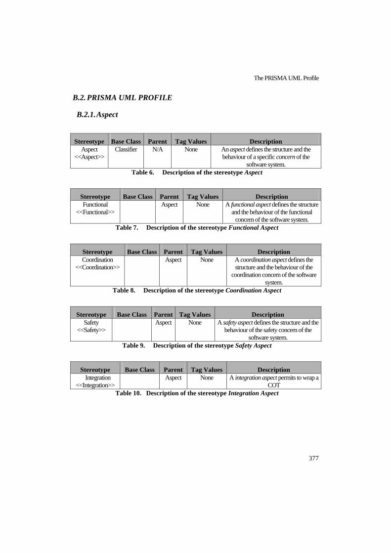
The PRISMA UML Profile
377
B.2. PRISMA UML PROFILE
B.2.1. Aspect
Stereotype Base Class Parent Tag Values Description Aspect
<<Aspect>> Classifier N/A None An aspect defines the structure and the
behaviour of a specific concern of the software system.
Table 6. Description of the stereotype Aspect
Stereotype Base Class Parent Tag Values Description Functional
<<Functional>> Aspect None A functional aspect defines the structure
and the behaviour of the functional concern of the software system.
Table 7. Description of the stereotype Functional Aspect
Stereotype Base Class Parent Tag Values Description Coordination
<<Coordination>> Aspect None A coordination aspect defines the
structure and the behaviour of the coordination concern of the software
system. Table 8. Description of the stereotype Coordination Aspect
Stereotype Base Class Parent Tag Values Description Safety
<<Safety>> Aspect None A safety aspect defines the structure and the
behaviour of the safety concern of the software system.
Table 9. Description of the stereotype Safety Aspect
Stereotype Base Class Parent Tag Values Description Integration
<<Integration>> Aspect None A integration aspect permits to wrap a
COT Table 10. Description of the stereotype Integration Aspect

PRISMA: Aspect-Oriented Software Architectures
378
Figure 164. Modelling of the stereotype Aspect
B.2.2. Component
Stereotype Base Class Parent Tag Values Description Component
<<Component>> Component
N/A None A component is an architectural
element that captures a given functionality of a software system. . As such, components do not have a
coordination aspect. Table 11. Description of the stereotype Component
Figure 165. Modelling of the stereotype Component

The PRISMA UML Profile
379
Stereotype Base Class Parent Tag Values Description Connector
<<Connector>> PRISMA
Component None A connector is an architectural
element that acts as a coordinator between other architectural
elements. As such, connectors have a coordination aspect.
Table 12. Description of the stereotype Connector
Stereotype Base Class Parent Tag Values Description System
<<System>> PRISMA
Component None A PRISMA system is a
component that includes a set of connectors, simple
components, and other systems that are correctly attached to one another.
Table 13. Description of the stereotype System
B.2.3. Port
Stereotype Base Class Parent Tag Values Description Port
<<Port>> Interface
N/A None A Port is an interaction point of an
architectural element (component or connector).
Table 14. Description of the stereotype Port
Figure 166. Modelling of the stereotype Port

PRISMA: Aspect-Oriented Software Architectures
380
B.2.4. Protocol
Stereotype Base Class Parent Tag Values Description Protocol
<<Protocol>> StateMachine
N/A None APprotocol establishes how the services
of an aspect can be executed. Table 15. Description of the stereotype Protocol
Figure 167. Modelling of the stereotype Protocol
B.2.5. Weaving
Stereotype Base Class Parent Tag Values Description Weaving
<<Weaving>> Dependency
N/A None A Weaving defines how the execution of a
service of an aspect can trigger the execution of a service of another aspect.
Table 16. Description of the stereotype Weaving
Figure 168. Modelling of the stereotype Weaving
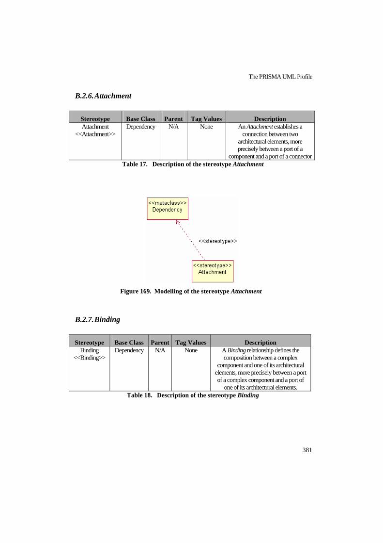
The PRISMA UML Profile
381
B.2.6. Attachment
Stereotype Base Class Parent Tag Values Description Attachment
<<Attachment>> Dependency
N/A None An Attachment establishes a
connection between two architectural elements, more precisely between a port of a
component and a port of a connector Table 17. Description of the stereotype Attachment
Figure 169. Modelling of the stereotype Attachment
B.2.7. Binding
Stereotype Base Class Parent Tag Values Description Binding
<<Binding>> Dependency
N/A None A Binding relationship defines the
composition between a complex component and one of its architectural
elements, more precisely between a port of a complex component and a port of
one of its architectural elements. Table 18. Description of the stereotype Binding
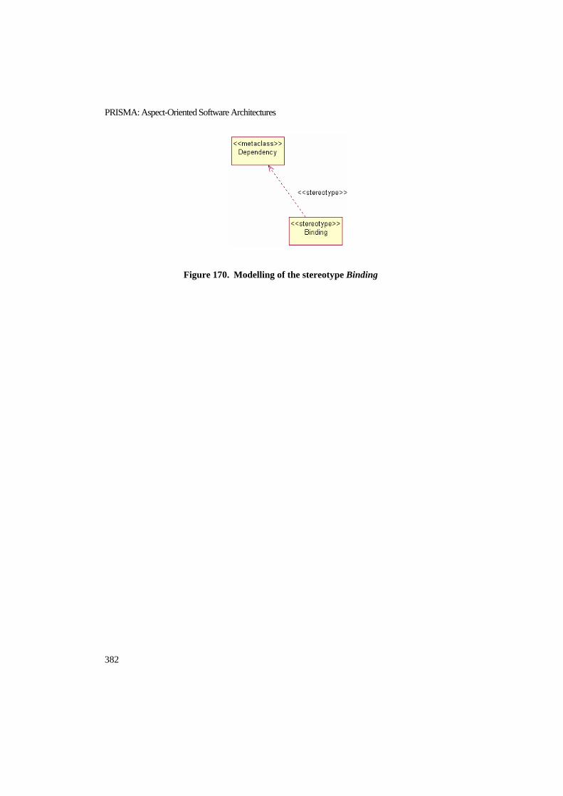
PRISMA: Aspect-Oriented Software Architectures
382
Figure 170. Modelling of the stereotype Binding

PRISMA Software Architecture of the TeachMover
383
APPENDIX C C. PRISMA SOFTWARE ARCHITECTURE
OF THE TEACHMOVER
This appendix presents the complete specification of the Joint system of the TeachMover robot
using the PRISMA AOADL as well as the specification of its instances Base, Shoulder and
Elbow. This specification has been automatically generated by the PRISMACASE. The
complete specification of the TeachMover can be found in [PRI06].
C.1. COMMON
Transformation_Functions
FTransHalfStepsToAngle (input Steps : integer, output RAngle : integer);
End_Transformation_Functions;
Domains
natural,
integer,
double,
char,
string,
boolean,
date,
End_Domains;

PRISMA: Aspect-Oriented Software Architectures
384
C.2. INTERFACES
Interface IPosition
newPosition (input NewSteps : integer);
currentPosition (output Pos : integer);
End_Interface IPosition;
Interface IRS232
send (input Joint : integer, input Steps : integer,
input Speed : integer, output Move : boolean);
stopRobot (input Joint : integer);
End_Interface IRS232;
Interface Iread
moveOk (output Success: boolean);
End_Interface IRead;
Interface IMotionJoint
moveJoint(input NewSteps: integer, input Speed: integer);
stop();
End Interface IMotionJoint;
Interface IJoint
moveJoint (input NewSteps: integer, input Speed: integer);
cinematicsMoveJoint (input NewAngle: integer, input Speed: integer);
stop ();
moveOk (output Success: boolean);
End_Interface IJoint;

PRISMA Software Architecture of the TeachMover
385
C.3. ASPECTS
Integration Aspect RS232 using IRS232, IMotionJoint, IRead
Services
begin();
in/out send (input Joint : integer, input Steps : integer,
input Speed : integer, output Move : boolean);
out stopRobot(input Joint : integer);
in moveJoint (input NewSteps: integer, input Speed: integer);
in stop ();
out moveOk (output Success: boolean);
end ();
PlayedRoles
INTMOVE for IMotionJoint ::= moveJoint ? (NewSteps, Speed)
+ stop ? ();
INTLISTEN for IRead ::= moveOk ! (Success);
Protocol
RS232 = begin MOTION;
MOTION = (INTMOVE_stop ? ():0
stopRobot ! (Joint):0 MOTION)
+ (INTMOVE_moveJoint ?(Newhalfsteps, Speed):1
send ! (Joint, Steps, Speed, Move):1) MONITOR
+ end;
MONITOR = (send ? (Joint, Steps, Speed, Move):1
INTLISTEN_ moveOk ! (Move):1 MOTION)
+ end;
End Integration Aspect RS232;

PRISMA: Aspect-Oriented Software Architectures
386
Functional Aspect FJoint using IPosition
Attributes
Variable
halfSteps : integer, NOT NULL;
Derived
angle: integer, derivation:
FtransHalfStepsToAngle(halfSteps);
Services
Begin (input IniPos : integer);
Valuations
[begin(IniPos) ]
halfSteps:=IniPos;
in newPosition (input NewSteps : integer)
Valuations
[newPosition (NewSteps)]
halfSteps:=halfSteps + NewSteps;
in/out currentPosition (output Pos : integer);
Valuations
[in currentPosition (Pos)]
Pos:=halfSteps;
end();
PlayedRoles
UPDATE for IPosition ::= newPosition ? (NewSteps)
+ (currentPosition ? (Pos)
currentPosition ! (Pos)); Protocol
FJOINT ::= begin(IniPos):1 POS
POS ::= UPDATE_ newPosition ? (NewSteps):1 POS
+ (UPDATE_currentPosition ? (Pos) :1
UPDATE_currentPosition ! (Pos) :1) POS;
+ end():1
End Functional Aspect FJoint;

PRISMA Software Architecture of the TeachMover
387
Safety Aspect SMotion, IPosition
Attributes
Constant
minimum, maximum: integer;
Variable
checkPos: integer;
Services
Begin ( input InitMinimum: integer, input InitMaximum: integer);
Valuations
[begin (InitMinimum, InitMaximum)]
minimum := InitMinimum,
maximum := InitMaximum;
in/out check (input Degrees: integer, output MovSecure: boolean);
Valuations
{(Degrees >= minimum) and (Degrees <= maximum)}
[in check (Degrees, MovSecure)] MovSecure := true;
{(Degrees < minimum) or (Degrees > maximum)}
[in check (Degrees, MovSecure)] MovSecure := false;
in/out controlSpeed (input CurrentSpeed: integer,
output SpdSecure: boolean);
Valuations
{(CurrentSpeed >= 1) and (CurrentSpeed <= 180)}
[in controlSpeed (CurrentSpeed, SpdSecure)]
SpdSecure := true;
{(CurrentSpeed < 1) or (CurrentSpeed > 180)}
[in controlSpeed (CurrentSpeed, SpdSecure)]
SpdSecure := false;
in/out currentPosition (output Pos : integer);
Valuations
[in currentPosition (Pos)]
checkPos := Pos;
PlayedRoles
POS for IPosition ::= currentPosition ! (Pos)
currentPosition ? (Pos); Transactions
in DANGEROUSCHECKING (input Steps: integer,
input CurrentSpeed:integer,
output Secure: boolean):

PRISMA: Aspect-Oriented Software Architectures
388
Coordination Aspect CProcessSuc using IMotionJoint, IJoint, IRead,
IPosition
Attributes
Variables
validMovement: boolean, DEFAULT: false;
Services
begin();
in/out moveJoint(input NewSteps : integer, input Speed : integer);
in/out stop()
in/out moveOk(output Success : boolean)
{Success=1} [in moveok(Success)] validMovement := true;
{Success=0} [in moveok(Success)] validMovement := false;
out newPosition(input NewSteps : integer)
end();
dangerousChecking = controlSpeed ! (CurrentSpeed, SpdSecure)
controlSpeed ? (CurrentSpeed, SpdSecure)
CURRENTPOS;
CURRENTPOS = (POS_currentPosition ! (Pos)
POS_currentPosition ? (Pos)) SAFESTEPS;
SAFESTEPS = check ! (FTransHalfStepsToAngle (checkPos),
MovSecure)
check ? (FTransHalfStepsToAngle (checkPos),
MovSecure);
Valuations
{(MovSecure = true) and (SpdSecure = true)}
[in DANGEROUSCHECKING(Steps, CurrentSpeed, Secure)]
Secure := true;
{(MovSecure = false) or (SpdSecure = false)}
[in DANGEROUSCHECKING(Steps, CurrentSpeed, Secure)]
Secure := false;
Protocol
SMOTION = begin():1 POS
CHECKING= DANGEROUSCHECKING ? (Steps, CurrentSpeed, Secure):1
CHECKING + end():1;
End Safety Aspect SMotion;

PRISMA Software Architecture of the TeachMover
389
C.4. ARCHITECTURAL ELEMENTS
Component Actuator
Integration Aspect Import RS232;
Ports
PCoord : IMotionJoint,
Played_Role RS232. INTMOVE;
End_Ports;
new(){RS232.begin();
destroy(){RS232.end();}
End_Component Actuator;
Preconditions
newPosition(NewSteps) if (validMovement = true)
PlayedRoles
SEN for IRead ::= moveOk ? (Success);
ACT for IMotionJoint ::= stop ! ()
+ moveJoint ! (NewSteps, Speed);
JOINT for IJoint ::= stop ? ()
+ moveOk ! (Success)
+ moveJoint ? (NewSteps, Speed);
POS for IPosition ::= newPosition ! (NewSteps);
Protocol
CPROCESSSUC ::= begin():1 COOR
COOR ::= (JOINT_stop?():0 ACT_stop!() :0) COOR
+ (JOINT_moveJoint?(NewSteps, Speed):1
ACT_moveJoint!(NewSteps, Speed)):1 COOR
+ (SEN_moveOk?(Success):1
POS_newPosition!(NewSteps):1
JOINT_moveOk!(Success):1) COOR
End Coordination Aspect CProcessSuc;

PRISMA: Aspect-Oriented Software Architectures
390
Connector CnctJoint
Coordination Aspect Import CProcessSuc;
Safety Aspect Import SMotion;
Weavings
SMotion. DANGEROUSCHECKING(NewSteps, Speed, Secure)
beforeif (Secure = true)
CProcessSuc.movejoint(NewSteps, Speed);
End_Weavings;
Ports
PAct : ImotionJoint,
Played_Role CProcessSuc.ACT;
PSen : IRead,
Played_Role CProcessSuc.SEN;
PJoint : IJoint,
Played_Role CProcessSuc.JOINT;
PPos : IPosition,
Played_Role CProcessSuc.POS;
End_Ports
new(input Argmin: integer, input Argmax: integer)
{CProcessSuc.begin();
SMotion.begin(input InitMinimum: integer,
input InitMaximum : integer); }
Component Sensor
Integration Aspect Import RS232;
Ports
PCnct : IRead,
Played_Role RS232. INTLISTEN;
End_Ports;
new(){RS232.begin();}
destroy(){RS232.end();}
End_Component Sensor;

PRISMA Software Architecture of the TeachMover
391
System Joint
Functional Aspect Import FJoint;
Ports
PJointSystem : IJoint,
Played_Role CProcessSuc.JOINT;
End_Ports
Import Architectural Elements Actuator, CnctJoint, Sensor,
WrappAspSys;
Attachments
AttchActCnct: CnctJoint.PAct(1,1)<--> Actuator.PCoord(1,1);
AttchSenCnct: CnctJoint.PSen(1,1)<--> Sensor.PCnct(1,1);
AttchPos: CnctJoint.PPos(,1)<--> WrappAspSys.PPosition(1,1);
End_Attachements;
Bindings
BndJCnct: PJointSystem(1,1)<--> CnctJoint.PJoint(1,1);
End_Bindings;
Component WrappAspSys
Functional Aspect Import FJoint;
Ports
PPosition : IPosition,
Played_Role FJoint.UPDATE;
End_Ports;
new(input ArghalfSteps: integer)
{ FJoint.begin(input IniPos : integer); }
destroy(){ FJoint.end();}
End_Component WrappAspSys;
destroy(){ CProcessSuc.end();
SMotion.end();
}
End_Connector CnctJoint;

PRISMA: Aspect-Oriented Software Architectures
392
C.5. CONFIGURATION
Architectural_Model_Configuration
TeachMoverJoints = new TeleOperationDomainJoints{
BASE = new Joint(0,1,1,1,1,1,1,1)
{BaseWrappAspSys = new WrappAspSys(0);
BaseActuator= new Actuator();
BaseConnector = new CnctJoint(90, -90);
new(input ArghalfSteps, input num_Actuator: integer, input num_CnctJoint: integer, input num_Sensor: integer, input num_AttActCnct: integer, input num_AttSenCnct: integer, input num_BndJCnct: integer) { new WrappAspSys(input ArghalfSteps: integer)); new Actuator(); new CnctJoint new(input Argmin: integer, input Argmax:integer);
new Sensor();
new AttActCnct(input ArgCnctName: string, input ArgCnctPort: string, input ArgCompName: string, input ArgCompPort: string); new AttSenCnct(input ArgCnctName: string, input ArgCnctPort: string, input ArgCompName: string, input ArgCompPort: string); new AttchPos(input ArgCnctName: string, input ArgCnctPort: string, input ArgCompName: string, input ArgCompPort: string); new BndJCnct(input ArgSysPort: integer, input ArgAEName: integer, input ArgAEPort: integer); } destroy(){ destroy Actuator(); destroy CnctJoint(); destroy Sensor(); destroy WrappAspSys(); destroy AttActCnct(); destroy AttSenCnct(); destroy AttchPos(); destroy BndJCnct(); } End_System Joint;

PRISMA Software Architecture of the TeachMover
393
BaseSensor= new Sensor();
BaseAttActCnct= new AttActCnct(BaseConnector, PAct, BaseActuator, PCoord); BaseAttSenCnct= new AttSenCnct(BaseConnector, PSen, BaseSensor, PCnct); BaseAttchPos= new AttchPos(BaseConnector, PPos, BaseWrappAspSys, PPosition); BaseBndJCnct= new BndJCnct(PJointSystem, PJoint,
BaseConnector);}
SHOULDER = new Joint(0,1,1,1,1,1,1,1)
{ShoulderWrappAspSys = new WrappAspSys(0);
ShoulderActuator= new Actuator();
ShoulderConnector = new CnctJoint(144, -35);
ShoulderSensor= new Sensor();
ShoulderAttActCnct= new AttActCnct(ShoulderConnector, PAct, ShoulderActuator, PCoord); ShoulderAttSenCnct= new AttSenCnct(ShoulderConnector, PSen, ShoulderSensor, PCnct); ShoulderAttchPos= new AttchPos(ShoulderConnector, PPos, ShoulderWrappAspSys, PPosition); ShoulderBndJCnct= new BndJCnct(PJointSystem, PJoint,
ShoulderConnector);}
ELBOW = new Joint(0,1,1,1,1,1,1,1)
{ElbowWrappAspSys = new WrappAspSys(0);
ElbowActuator= new Actuator();
ElbowConnector = new CnctJoint(0, -149);
ElbowSensor= new Sensor();
ElbowAttActCnct= new AttActCnct(ElbowConnector, PAct, ElbowActuator, PCoord); ElbowAttSenCnct= new AttSenCnct(ElbowConnector, PSen, ElbowSensor, PCnct); ElbowAttchPos= new AttchPos(ElbowConnector, PPos, ElbowWrappAspSys, PPosition); ElbowBndJCnct= new BndJCnct(PJointSystem, PJoint,
ElbowConnector);}
}

PRISMA: Aspect-Oriented Software Architectures
394

Acronyms
395
ACRONYMS
ADL Architecture Description Language
AOADL Aspect-Oriented Architecture Description Language
AOP Aspect-Oriented Programming
AOSD Aspect-Oriented Software Development
CASE Computer-Aided Software Engineering
CBSD Component-Based Software Development
CCS Calculus of Communicating Systems
CF Composition Filters
CLR Common Language Runtime
CLS Common Language System
COTS Commercial Off-The-Shelf
CSP Communicating Sequential Processes
CTS Common Type System
DSL Domain-Specific Language
FIFO First In First Out
GUI Graphical User Interface
PRISMA: Aspect-Oriented Software Architectures
396
MDA Model Driven Architecture
MDE Model–Driven Engineering
MDD Model-Driven Development
MDSOC Multi-Dimensional Separation of Concerns
MSIL MicroSoft Intermediate Language
MUC Mechanism Unit Controller
OCL Object Constraint Language
OOP Object-Oriented Programming
PC Personal Computer
RUC Robot Unit Controller
SEI Software Engineering Institute
SoC Separation of Concerns
STD State Transition Diagram
SUC Simple Unit Controller
UML Unified Modelling Language

Index
397
INDEX
π
π- calculus · 223 π-calculus · 117, 118, 134, 205, 220, 222
monadic π-calculus · 119 naming · 119 polyadic π-calculus · 119 prefix · 119 π-calculus with priorities · 120
A
AAM · 79 ACM · 79 Advice · 65, 144
After · 65 After Returning · 66 After Throwing · 66 Around · 65 Before · 65
After · 65, 143, 145, 287, 365 After Returning · 66 After Throwing · 66 Afterif · 143, 147, 287, 365 Alias · 180 Analysis · 57 AODM · 79 AOP .NET Technologies · 275 AORE · 75 AOSD/UC · 76
Use Case Module · 76 Use Case Slice · 76
Architectural Element · 131, 142, 152, 159, 186, 284, 379, 381
Aspect · 175 Formalization · 152 Port · 186, 197 Weaving · 186, 189
Architectural Model · 102 Architectural Style · 53 Architectural Views of Aspects · 93 Architecture Description Language · 41, 53, 85, 102
Architecture Specification · 198 ARGM · 76 Arithmetic Expression · 372 Around · 65 ASAAM · 92 Aspect · 60, 66, 69, 86, 129, 138, 143, 152, 175, 258, 281, 360, 377, 382
Attribute · 138, 176, 178 Behaviour · 139 Changes of State · 138 Composition · 68 Constraint · 138, 141, 176, 181 Context-awareness · 140 Coordination · 138, 139, 152, 153, 154, 229, 378, 379 Definition · 102 Distribution · 139 Formalization · 140 Functional · 139 Instantiation · 67 Integration · 140 Interface · 138 Management · 68 Mobility · 140 Order · 68 Played_role · 138 Played_Role · 177, 184 Precondition · 138, 141, 177, 182 Private · 138, 139 Protocol · 177, 185, 380 Public · 138, 139 Safety · 138, 139, 151, 153, 229 Semantics · 138 Service · 138, 143, 176, 380 Services · 138 State · 66, 138 Structure · 138 Valuation · 138, 140, 177, 183
Aspect Collaboration Interface · 97 Aspect Component · 95, 96, 97, 100 Aspect Oriented Programming · 64 AspectJ · 60 AspectLeda · 94 Aspect-Oriented Architecture Description
Language · 29 Aspect-Oriented Component Engineering · 95 Aspect-Oriented Evolution · 102

PRISMA: Aspect-Oriented Software Architectures
398
Aspect-Oriented Model · 101 Aspect-Oriented Programming · 59, 62
Data Type System · 67 Properties · 66 Semantics · 68
Aspect-Oriented Software Development · 29, 31, 61 Asymmetric Model · 69 Symmetric Model · 69
Asymmetric Model · 69 Asynchronous · 280 ATAM · 43 ATRIUM · 77 Attachment · 52, 133, 154, 192, 262, 290, 366, 381
AttachmentClientBase · 290 AttachmentServerBase · 290 Communication Pattern · 193 Formalization · 155
Attribute · 176, 178 Constant · 179, 361 Derived · 178, 361 Non-derived · 178 Variable · 179, 361
Automatic Code Generation · 31
B
Base Code · 64 Before · 65, 143, 146, 287, 365 Beforeif · 143, 149, 287, 365 Binding · 133, 159, 195, 262, 290, 292, 367
Communication Pattern · 196 ComponentBinding · 292 Formalization · 159 SystemBinding · 292
Bindings · 53 BNF PRISMA AOADL · 36, 359
Block · 359 Instance · 370 List · 359 Name · 359 Sequence · 359 Value · 359
C
Caesar · 97 Calculus of Communicating Systems (CCS) ·
118 CAM/DAOP · 88 Class Diagram · 79 Classifier · 80 CLR · 276 CLS · 277 CoCompose · 80 Code Generation Pattern · 266
Aspect · 267 Component · 266
Collaboration Diagram · 79 Communication · 57 Complex Component · 53 Component · 47, 99, 132, 152, 154, 164, 186, 190, 261, 285, 365, 378, 381 Component View · 96 Component-Based Software Development · 29, 30 Composition Filters · 72
Filter · 72 Superimposition · 73
Composition Relationship · 53 Computer-Aided Software Engineering · 29 Concern · 60, 130, 138, 139, 175, 282, 377 Concern Space · 70 Condition · 372 Configuration Model · 271
Modelling Tool · 271 Specification · 369
Connection · 52 Connector · 49, 88, 98, 132, 152, 154, 186, 191, 261, 285, 366, 379 Constraint · 56, 176, 181, 363
Dynamic · 181 Static · 181
CORE · 76 Cosmos · 77 COTS · 31, 140, 260 Crosscutting-Concerns · 60, 64, 66, 130 CTS · 277
D
DAOP · 88 Data Type · 371 Delegate · 277 Domain Specific Language · 249 Domain-Specific Model · 245, 250 DotNET Remoting · 277 DotNET technology · 246 DotNET Technology · 275

Index
399
DSL Tools · 249 Code Generation Designer · 252 Debugging Solution · 252 Domain Model · 250, 252 Model Designer · 251, 252, 254 Setup · 256 Verification · 253, 263
Complete · 263 Hardconstraint · 254 Partial · 263 Verification Rule · 254
Dynamic Aspect Diagram · 80
E
Early Aspect · 75 EFTCoR · 112
F
Filter · 72 Formulae · 371 Functional Decomposition · 61, 64, 69 FuseJ · 99
G
Goal-Oriented Requirements Engineering · 76 Graphical Modelling · 103 GREMSoC · 76
H
Hyper/J · 70, 77 Concern Space · 70 Encapsulation · 70, 71 Hyper/JTM · 70 Hypermodule · 71 Hyperslice · 71 Hyperspace · 71 Identification · 70 Integration · 70, 71 Relationship Definition · 70, 71
Hypermodule · 71 Hyperslice · 71 Hyperspace · 71
Hyperspaces · 70
I
InPorts · 286 Instead · 143, 147, 287, 365 Insteadif · 144, 150, 287, 365 Interface · 47, 131, 132, 134, 137, 138, 142, 164, 173, 206, 257, 360 InterfaceService · 173
J
JAC · 100 Jiazzi · 100
Linking Unit · 101 Unit · 101
Join Point · 64 Joint · 113
K
Kinds of Aspects · 282 Kripke Structure · 118
L
Language for PRISMA Protocols · 223 Log · 299
M
Maintenance · 57 MDSOC · 70, 87
Hyper/J · 70, 77 Hyperspaces · 70 On-Demand Remodularization · 70
Memory Persistence · 295 Metaclass · 134, 171 Meta-level · 133 Metamodel · 133, 171
Utilities · 200 MiddlewareSystem · 295 Modal Logic of Actions · 117, 134, 140, 205, 307

PRISMA: Aspect-Oriented Software Architectures
400
Model-Driven Architecture · 249 Model-Driven Development · 29, 32, 245,
249, 300, 303 Model–Driven Engineering · 245 MSIL · 276
N
Non-UML language · 80
O
Object Constraint Language (OCL) · 171 Object-Oriented Programming · 61 Obliviousness · 62 On-Demand Remodularization · 70 OutPorts · 286
P
Package · 79 Paradigm of Automatic Programming · 29, 31 Parameter · 371 Perspectival Concern-Space · 87 Played_Role · 137, 138, 142, 155, 159, 164, 177, 184, 281, 364
Compatible · 154, 159 Formalization · 137
Pointcut · 65, 76, 144 Port · 52, 131, 142, 152, 154, 155, 159, 160, 164, 186, 197, 261, 284, 285, 366, 381
Formalization · 142 Interface · 142 Played_Role · 142 Type · 142
Precondition · 177, 182, 362 Prism · 131 PRISMA · 77, 129
AOADL · 246 CASE · 245 Methodology · 29, 303
PRISMA CASE · 29 PRISMA Graphical AOADL · 257 PRISMA model · 29 PRISMA Model Compiler · 264 PRISMA Modelling tool · 256 PRISMANET · 247
Architecture · 275
Log · 278 Memory Persistence · 278 PRISMA Execution Model · 277, 279
Communication Module · 279 Communications Module · 277 Type Module · 277, 279
Transaction Manager · 278 Property · 56 Protocol · 139, 177, 185, 260, 364, 380
Q
Quantification · 62
R
Reflection · 277 Reuse · 56
S
SAAM · 43, 92 Scenarios Model · 77 Separation of Concerns · 59, 85 Serialization · 277 Service · 134, 135, 137, 176, 180, 282, 362
Alias · 180 Begin · 362 End · 362 Formalization · 136, 144 Invocation · 135, 144, 155, 156, 160, 161 Private · 135, 282 Process · 136 Public · 135, 282 Semantics · 135 Signature · 134, 174, 206 Transaction · 180 Type · 180
Software Architecture · 39, 40, 56, 86 Analysis · 43, 57, 92 Definition · 44 Description · 54, 55 Evolution · 91 Properties · 41, 43, 56
Design · 42 Quality Attributes · 43
Software Architecture Evolution · 57 Software Architectures · 30

Index
401
Software Factories · 249 State · 260 State Transition Diagram · 260 Substate · 260 Superimposition · 73, 90 Symmetric Model · 69 Symmetrical · 130 System · 53, 132, 159, 164, 186, 194, 261, 294, 367, 379
Binding · 195 Composition · 165
Inclusive · 165 Weak · 165
Emergent Behaviour · 164 Formalization · 165 Pattern · 164
T
Tangled Code · 60 TeachMover · 113
Actuator · 115 Base · 113 Elbow · 113 Mechanism Unit Controllers (MUCs) · 117 Robot Unit Controlers (RUCs) · 117 Sensor · 115 Shoulder · 113 Tool · 114 Wrist · 113
Tele-operation Domain · 111 Tele-operation Systems · 112 Theme · 77 Theme/Doc · 77 Theme/UML · 79 TOPSA · 43 Transaction · 180, 296
Active · 298 Committed · 298 Precommitted · 298 Prerollback · 298 Rollbacked · 298 Transactional Context · 297 TransactionLog · 298
Transaction Manager · 296 Transat · 91
U
UFA · 79 UML · 78
Heavy Extension Mechanism · 79 Light Extension Mechanism · 79 Profile · 79
Understanding · 56 Unified Modelling Language (UML) · 171 UXF · 80
V
Valuation · 177, 183, 362 Condition · 183 Postcondition · 183 Service · 183
Valuations · 137 V-Graph · 77 View · 93, 96 Viewpoint · 75 Views · 42, 55
W
Weaving · 65, 66, 131, 143, 152, 164, 186, 189, 262, 284, 287, 365, 380
Advice Service · 189 Definition · 102 Dynamic · 66 Formalization · 144 Operator · 145, 365
After · 143, 145, 287, 365 Afterif · 143, 147, 287, 365 Before · 143, 146, 287, 365 Beforeif · 143, 149, 287, 365 Instead · 143, 147, 287, 365 Insteadif · 144, 150, 287, 365
Operators · 143 Pointcut Service · 189 Set · 151 Static · 66 Weaving Time · 66
Weaving Manager · 287

PRISMA: Aspect-Oriented Software Architectures
402