· PDF filePrintware Click on desired ... preventive maintenance, and ... d. Double-click on...
236
LEADERS IN COMPUTER TO PLATE Printware Click on desired manual: 1270 Eagan Industrial Road, St. Paul, MN 55121 • Phone: 800-456-1400 • Fax: 651-454-3684 • http://PrintwareInc.com Service Manual Quick Start Guide Installation Guide Operator Manual Illustrated Parts List Illustrated Parts List
Transcript of · PDF filePrintware Click on desired ... preventive maintenance, and ... d. Double-click on...

LEADERS IN COMPUTER TO PLATEPrintware
Click on desired manual:
1270 Eagan Industrial Road, St. Paul, MN 55121 ••••• Phone: 800-456-1400 ••••• Fax: 651-454-3684 ••••• http://PrintwareInc.com

Quick Start Guide
700631 Rev B
LEADERS IN COMPUTER TO PLATE
PlateStream SCPlatesetter

QUICK START GUIDE
QS-1
Introduction
Loading Plate Material
Control Panel Setup Menu
RIP Setup & Imaging Plates
Contents
QS-2
QS-2
QS-3
QS-4

QUICK START GUIDE
QS-2
Loading Plate Material1. Open the top cover. Raise marker by pulling the marker lever up until lever stops. Gently lift upmarker. If you are replacing the roll of plate media, the last of the previouos roll may need to be removedfrom the platesetter.
2. Remove the spool assembly from the Platesetter.
3. Adjust the rear edge guide inside the Platesetter by pulling the edge guide knobs out and sliding to theposition closest to the plate media width. Adjust the front edge guide by loosening the screws andmoving the guide all the way to the front.
4. Adjust the left hub on the spool shaft to match the edge guide position by squeezing the clip and slidingon shaft. Remove the right hub from the shaft by lifting clip and sliding off the shaft. Slide media ontoshaft. Slide the right hub onto shaft by lifting clip and pushing down on spool until spool is tight againstmedia (see Figure QS-1).
5. Place the spool assembly back onto the receptacles in the Platesetter. Feed media through rollers andtwo edge guides. Adjust the front edge guide by turning edge guide knob counterclockwise and slidingedge guide until edge guide rests against plate media. Lock edge guide by turning knobs clockwise. Feedthe media by hand up to the nip of the capstan roller and engage (hold down) the load switch for approxi-mately 5 seconds. Watch so that the feed side of the capstan roller picks up on the media and begins totransport it. After the media has fed past the exit side pinch roller, release the load switch. Manually turnthe exit side pinch roller approximately 2 revolutions counterclockwise to remove the loop, which mayhave formed over the capstan roller during the load. This last step will help the registration of the first fewplates output from the platesetter after this load sequecnce as compared with previously output plates orones that may be output later.
6. Gently lower the marker and lock down by pushing the marker down until the lever is horizontal. Closethe top cover.
7. Set the plate width from the control panel setup menu. Load media from the control panel. Image onetest plate from the control panel Test Plate menu.
IntroductionFor detailed procedures on the control panel, plate media and chemistry, preventive maintenance, andtrouble-shooting, see the PlateStream SC Operator Manual.
Before making a plate, the Platesetter must be:• Connected to the RIP—the I/O connectors are located on the rear of the top cover of the machine.• Ready to accept a job (Main Menu displayed on the control panel, On-Line state, no error conditions).• The processing tanks must be filled to proper levels.

QUICK START GUIDE
QS-3
Control Panel Setup Menu
The control panel Setup Menu (below) lists fixed and changeable options for changing various Platesetterparameters.
1 ON/+
OFF/-
2 3 4 5
6 7 8 9 0
ESC
ENTER
Setup: [ESC to exit]
1. Image: Negative-Right Reading2. Resolution: 1800 DPI3. Image Power: 55%4. Media Width: 13.12" (Spool Pos: 13)5. Input Spool: A6. Destination: Processor7. Display Units: English
1. Image – Sets the type of imaging. The choices are: Positive or Negative Wrong Reading, and Positive or Negative Right Reading. The default is Negative-Right reading for plate media.
2. Resolution – Preset at 2400 DPI.
3. Image Power – Sets the image power (laser intensity).
4. Media Width: xx.xx" (Spool Pos: yy) — Media Width is the exact width, entered by the operator, from7.00" to 13.40" (17.78 cm to 34.00 cm). Spool Pos indicates the position to set the spool or cassette. Spoolposition is set at the media width in inches, rounded to the nearest inch, from 7 to 13.
5. Input Spool – Specifies the input spool. The choices are: A, B, C, D.
6. Destination – Preset at “Processor.”
7. Display Units – Toggles between English and Metric display units.
Figure QS-1. Loading Plate Media on Spool

QUICK START GUIDE
QS-4
ZAPrip HQ (Harlequin) RIP Setup; Imaging Plates
1. Startup the RIPa. Connect the RIP to the network and turn it on.b. Press ctrl-alt-del on the RIP to log into Windows NT.c. Log in as Administrator with password: printware.
d. Double-click on the Navigator icon to launch the RIP.
2. Create appropriate page setup(s) in Page Setup Managera. Ensure that the “Negative” box is unchecked.
b. Specify plate size and image positioning in the page layout menu.
c. You can specify screens in the Screening menu, or leave it at factory defaults: Override fre-quency and spot function; Euclidean Spot Function; 100 to 150 lpi frequency; the defaultAngles; Use Harlequin Precision Screening; and Rotate screens according to Page Rotation.
3. Publish the Page Setup on the network in Input ControllerThe name associated with the Page Setup in Input Controller will show up on the front-end computer.
Note: You may want to specify a name which incorporates resolution, plate size, or the target press(e.g., “Quickmaster2up2400dpi”).
4. Choose Start Inputs (the green traffic light icon) from the RIP menu.
5. Set up the front-end computer to print to the RIPFor best results, use the Adobe print driver and PlateStream PPD. These are provided with the RIP.If you don't have the Adobe driver, the Linotype 630 driver can be used.
Note: On Windows front-ends, specify the platesetter as a Local Printer not a “Network Printer.”This allows selection of the correct spool folder at print time.
6. Print the Job a. On Mac front-ends, ensure that the appropriate device name has been selected in Chooser, and print normally from the application. Do not specify screens or resolution in the application.
b. On Windows front-ends, print to file from the application using the printer set up in step 3 (thedefault printer name is PlateStream when using the PlateStream PPD). Select the ZAPrip HQ and theappropriate hot folder (Quickmaster2up2400dpi in our example) as the destination by browsingNetwork Neighborhood. Select the PlateStream PPD if the application supports PPDs. Do notspecify screens or resolution in the application.

Installation Manual
700632 Rev B
LEADERS IN COMPUTER TO PLATE
PlateStream SCPlatesetter

INSTALLATION GUIDE
I-1
Contents
Pre-Installation ChecklistConfirm Electrical RequirementsConfirm Supply of Recommended ConsumablesConfirm Arrival of the PlatesetterVerify Final Location
Precautions
Unpacking and Inspection
Assembling the Platesetter
Assembling the Processor
Installing the Raster Image Processor (RIP)
Turning On the Platesetter
Loading Plate Material
Setting Replenishment Rates
Changing Processor - 50-60 HZ
Calibrate Processor
Physical CalibrationOverviewCutter SkewTransport SkewImage SkewScan Width and Linearity AdjustmentMarker Position AdjustmentAdjusting Image LengthAdjusting OverlapAdjusting Cut LengthAdjusting Backup LengthAdjusting Fogging Edge LEDAdjusting Miniplate Backup LengthPunch Alignment and SkewAdjusting Punch LengthDensity-Dot Calibration
De-Installing the Platesetter
Serial Numbers and Factory Settings
I-2I-2I-2I-2I-4
I-4
I-4
I-5
I-6
I-7
I-8
I-9
I-10
I-11
I-12
I-13I-13I-13I-14I-15I-17I-17I-18I-19I-19I-20I-20I-21I-22I-24I-25
I-26
I-29

PLATESTREAM PLATESETTER
INSTALLATION GUIDE
Pre-Installation Checklist
1. Confirm Electrical Requirements
Verify that the electrical power of the required voltage and current is available at the machine location.Verify an Ethernet network drop is available at the RIP location. The RIP requires a 10-Base-T or thincoaxial cable. The Platesetter requires a dedicated 200-240 VAC 20-amp, 60Hz three-wire single-phaseelectrical line. The platesetter can be switched to 50 Hz operation. A 100-120 VAC 15-amp, 50/60Hzline with a power strip is required for the Raster Image Processor (RIP). The RIP can be switched to 200-240 VAC operation.
The Platesetter is shipped without a power plug. The Platesetter power cord length is approximately 9'.The power plug used with the Platesetter must be rated for 20-amp 250-volt power and should have theproper safety certification for the country of use. The electrical wiring color codes are:
North America International
• Line: Black Brown
• Neutral: White Blue
• Ground: Green Green/Yellow
Verify that an electrician is available if needed.
2. Confirm Supply of Recommended Consumables
Have at least 16 gallons each of working Activator and Stabilizer on hand.
Have plate media available as required. Plate media may be either paper- or polyester-based. Roll widthmay be from 7” to 13.4” (17.8 cm to 34.0 cm). The maximum roll length is 280’ (85m).
3. Confirm Arrival of the Platesetter Verify the machine will be at the installation site (final location, loading dock, storage area, etc.) before scheduling installation. The Platesetter should be initially installed by an authorized service technician.
I-2
I-2

Recommended Supplies
I-3
RECOMMENDED CONSUMABLES FOR PLATESTREAM
PRINTWARE: SILVERSTREAM+
RED LIGHT PLATE MEDIA:
Emulsion In
5 mil polyester 808555-XXX (280 FT ROLLS)8 mil polyester 808666-XXX (280 FT ROLLS)
(Note: -XXX specifies the specific roll width from 7” to 13.4”)
CHEMISTRY:ACTIVATOR: 808777-001STABILIZER: 808777-002

INSTALLATION GUIDE
I-4
4. Verify Final Location
Select a suitable place for installation. Avoid excessive dust, vibration, and direct sunlight. The Platesetteris designed for use in a prepress environment. Acceptable ambient temperature range is 65°F to 80°F(18°C to 27°C) and acceptable relative humidity is 45 to 70%.
Check the necessary dimensions at the physical installation site (e.g. width of doors, etc.) with the Plateset-ter dimensions. To ensure optimal operation allow clearances of at least 12" (30 cm) on the left, 24" (75 cm)on the right, 30" (75 cm) in front, and 12" (30 cm) in the rear (see Figure I-1). After uncrating, the depth ofthe Platesetter (which is on casters) is approximately 33" (84 cm).
If a method for plumbing to remove chemical effluence is required, the method must meet local environmen-tal codes. An optional drain for the chemicals provided with the Platesetter is a vinyl flexible hose, 6' long,1 1/4" outer diameter, and 1" inner diameter.
Precautions1. Due to the 500 lb. (227 kg) weight of the Platesetter, use caution when removing Platesetter from pallet.
2. Follow electrostatic discharge (ESD) protective procedures when connecting cables or working nearPlatesetter PCAs, including:
• Ground yourself by touching the metal chassis of the Platesetter before connecting or disconnecting anycable.
• Use a wrist strap and an antistatic work surface, if possible, when handling PCAs or other electroniccomponents.
• Always store and transport PCAs in antistatic bags.
Unpacking and Inspection
Keep all the shipping boxes, braces, crates, and packing pieces in case the Platesetter needs to be repackaged.
1. Inspect the Platesetter crate for signs of shipping damage. Report any damage discovered to the carrierimmediately.
2. Remove the strapping, ramp, and the top cover from the crate.
4. Attach the ramp to bottom of the crate using the two pegs located on either short side of the crate.
3. Remove the cardboard sides.
5. Remove the plastic wrapping from the unit.

INSTALLATION GUIDE
I-5
6. Remove screws from the four wood blocks mounted to the bottom of the crate. Remove blocks by slightlylifting the Platesetter.
7. Roll the Platesetter down the ramp and on to the floor carefully.
Assembling the Platesetter1. Carefully open the carton containing the marker assembly.
2. Remove the second cardboard cover from the marker assembly.
3. Cut tie strap.
4. Identify the front and rear of the marker assembly (the front has a warning label and serial number; therear has a grounding strap and welded hinge brackets).
************************************************************************************CAUTION: Do not set the laser marker assembly down on a flat surface. This can damage the
resonant galvanometer on the side of the assembly.************************************************************************************
5. Raise the top cover. Remove tie straps and bubble pack from struts. Remove the caps on the outside ofeach strut head.
6. Locate the hinge shaft for attaching the marker assembly at the top inside left rear of the Platesetter.
7. Have two people lift the marker assembly from the carton using the C-shaped black handle located on thelaser end of the marker. Place the marker assembly in the Imager by placing the hinge brackets on thehinge shaft (not on the brass bushings).
8. Slide the marker assembly mounting clip onto the spring-loaded brass bushing closest to the Processor.
9. Lift the other end of the marker assembly and place it past the brass bushing. Slide the brass bushing into place.
10. Remove the long 1" wide piece of black tape from the bottom of the marker assembly by gently pullingon the loose end of the tape. Remove the C-shaped black shipping support by removing the eight screwsholding this support.
11. To attach the struts to the marker assembly:
• Raise the marker assembly until the ball joints on the outside line up with the strut heads.
• Firmly push the strut heads onto the ball joints and reattach the caps to lock the struts to the marker assembly.
12. Gently lower the marker assembly and lock by pushing the marker lever down until lever is horizontal.

INSTALLATION GUIDE
I-6
13. Remove bubble pack from cables. Connect the cables to the marker assembly as follows:
• Connect the grounding strap from the rear of the marker assembly to the Imager unit frame.
• Connect the 10-wire connector to connector J6 on the printed circuit card (PCA) assembly located on top of the marker assembly.
• Connect the ribbon cable from the rear I/O panel to connector J8 on the PCA.
• Connect the ribbon cable from the harness assembly to J9 on the PCA.
14. Open accessory boxes and remove bubble pack from contents. The contents should include:
a. The RIP and PlateStream manuals on CD’s.b. Two optional plastic replenishment tanks and optional small replenishment cart.c. Effluent tankd. A wire tray.e. Two media spools and one media shaft.f. Tube with plate samples.
15. Insert wire tray into slots located on the top right side of the Platesetter.
16. Attach customer supplied power plug to Platesetter power cord located in the rear of the machine perelectrical wiring codes.
Assembling the Processor
1. Remove black tape holding the activator and stabilizer racks. Remove the four styrofoam pieces locatedin the front and rear of the processor working tanks inside the Platesetter. Remove bubble pack wrappedaround Cover E, Guide F, and overflow tubes.
2. Place the overflow tubes in the large holes located in the rear of the processor working tanks, inside thePlatesetter. Press down until overflow tubes stop. Place the spring pin from Guide F into the hole locatedin the rear of the activator tank while placing the other pin into the hole located in the rear of the stabilizertank. Slide Guide F towards the rear of the Platesetter while placing pins on the other side of Guide F intothe holes located in the front of the activator and stabilizer racks.

INSTALLATION GUIDE
I-7
Make sure the activator tank is filled with activator and the stabilizer tank is filled with stabilizer. Place Cover E over processor working tanks.
5. Remove the bubble pack from the replenishment probes located underneath the processor and insert probes into the replenishment tanks by screwing on the white cap. Remove the bubble pack from the optional effluent probe located underneath the processor and insert probe into the hole on top of the effluent tank.
6. Rotate the gears in the activator and stabilizer racks several times to free them up before operating the Platesetter. Close the top cover.
Installing the Raster Image Processor (RIP)1. Unpack the RIP central processing unit (CPU) and inspect it for any obvious physical damage. If any
component appears damaged, notify the carrier immediately.
2. Unpack the RIP keyboard.
3. Unpack the RIP monitor.
4. Plug the monitor cable into the back of the RIP CPU (this cable should fit only one way).
5. Connect the keyboard cable to the keyboard connector on the back of the RIP CPU.
6. Attach the network cable to the network interface connector on the back of the RIP CPU.
7. Plug in the RIP electrical power cord(s).
8. Connect the two interface cables between the RIP CPU and the Platesetter. The Platesetter I/O Panelis located on the top rear of the machine (see Figure I-1).
3. Place the two optional replenishment tanks on the optional smaller cart.
4. If necessary prepare the Activator and the Stabilizer solutions in the replenishment tanks following themanufacturers instructions. Fill the processor working tanks inside the Platesetter and the replenishmenttanks with the solutions.

INSTALLATION GUIDE
I-8
Turning On the Platesetter1. The power switch for the Platesetter is located on the rear of the machine. To turn on the Platesetter, flip
the switch up (see Figure I-1).
• Each time the Platesetter power switch is turned on, the Platesetter performs a series of tests of itsinternal components. If an error message appears on the control panel, see the section Responding toControl Panel Error Messages in the PlateStream Operator Manual. If the display stops at anyinitialization point for more than five minutes, turn off the Platesetter and call for authorized service.
• The Platesetter boot-up procedure takes approximately four minutes. If best absolute accuracy is re-quired, allow six hours for the Platesetter to reach operating temperature.
• Once the power up sequence is successfully completed, the control panel screen will show the mainmenu with On Line mode indicated and no error messages displayed.
Figure I-1. Size and clearances for the Platesetter
P ow er Sw itch
R ear (I/O ) p a nel
12 "clea rance rear
24 " c leara nce rt
30 " c leara nce fron t
47 "
29 " 33 "
12 " clea ran ce le ft

INSTALLATION GUIDE
I-9
Loading Plate Media1. Open the top cover. Raise marker by pulling marker lever up until lever stops. Lift up marker gently.
2. Remove the spool assembly from the Platesetter.
3. Adjust the rear edge guides inside the Platesetter by pulling the edge guide knob up and sliding to the positionclosest to the plate media width. Adjust the front edge guide by loosening the screw and moving the guideall the way to the front.
4. Adjust the left hub on the spool shaft to match the edge guide position by squeezing the clip and sliding onshaft. Remove the right hub from the shaft by lifting clip and sliding off the shaft. Slide media onto shaft.Slide the right hub onto shaft by lifting clip and pushing down on spool until spool is tight against media (seeFigure I-2).
5. Place the spool assembly back onto the receptacles in the Platesetter. Feed media through rollers and twoedge guides. Adjust the front edge guide by turning edge guide knob counterclockwise and sliding edgeguide until edge guide rests against plate media. Lock edge guide by turning knob clockwise. Feed the mediaby hand up to the nip of the capstan roller and engage (hold down) the load switch. Watch so that the feedside of the capstan roller picks up on the media and begins to transport it. After the media has fed past the exitside pinch roller, release the load switch. Manually turn the exit side pinch roller approximately 2 revolutionscounterclockwise to remove the loop, which may have formed over the capstan roller during the load. Thislast step will help the registration of the first few plates that are output from the platesetter after this loadsequence as compared with plates processed previous to this load or plates that may be processed later.
6. Gently lower the marker and lock by pushing marker lever down until the lever is horizontal. Close the topcover.
7. Set the plate width from the control panel setup menu. Load media from the control panel. Image one testplate from the control panel Test Plate menu.
Figure I-2. Loading Plate Media on Spool
NOTES:
• Cut off any punched area of plate before reloading to ensure a reliable load.
• Media must be reloaded after jams or other fault conditions. In this case, a message will appear on the operator panel to “Reload Media” or “Manually Reload Media.”
• Media must be loaded with no tears or wrinkles.
MediaRoll
RightHub RightHubSpools Spools
Shaft ShaftPosition 13 Position 13
LeftHub
EMULSION OUT MEDIA EMULSION IN MEDIA
Left Hub

INSTALLATION GUIDE
I-10
Average Plate Size0.6 ft² 0.8 ft² 1.0 ft² 1.2 ft² 1.4 ft² 1.6 ft² 1.8 ft² 2.0 ft² 2.5 ft²0.06M² 0.07M² 0.09 M² 0.11 M² 0.13 M² 0.15 M² 0.17 M² 0.19 M² 0.23 M²
Printware SilverStream+ Activator & Stabilizer oz .23 .30 .38 .45 .53 .60 .68 .75 .94 Activator & Stabilizer ml 6.7 8.9 11.2 13.4 15.6 17.8 20.1 22.3 27.9
Agfa Setprint Plus Activator & Stabilizer oz .23 .30 .38 .45 .53 .60 .68 .75 .94 Activator & Stabilizer ml 6.7 8.9 11.2 13.4 15.6 17.8 20.1 22.3 27.9
Mitsubishi Silver DigiPlate Activator ounces .28 .38 .47 .57 .66 .75 .85 .94 1.18 Stabilizer ounces .38 .50 .63 .75 .88 1.01 1.13 1.26 1.57
Activator milliliters 8.4 11.2 13.9 16.7 19.5 22.3 25.1 27.9 34.9 Stabilizer milliliters 11.2 14.9 18.6 22.3 26.0 29.7 33.5 37.2 46.5
4. If more replenishment is required turn the screw on the pump clockwise, if less replenishment is requiredturn the screw counterclockwise. The screw for the stabilizer replenishment is located towards the frontof the pump, the screw for the activator is located towards the back of the pump. The adjustment screwhas a ten-turn range.
5. If the average plate size changes, the replenishment rate should be adjusted.
Setting Replenishment Rates
1. Remove front panel and remove replenishment hoses from the working tanks inside the processor. Place the replenishment hoses in measurement containers.
2. From the control panel run a test plate that represents the average plate size that will be run on this Platesetter.
3. Compare the measured volume to the table outlined below. Recommended replenishment rates are as follows:
Printware SilverStream+ Activator or Stabilizer 0.37 ounces/ft² (120 ml/M²)
Agfa Setprint Plus Activator or Stabilizer 0.37 ounces/ft² (120 ml/M²)
Mitsubishi Silver DigiPlate Activator: 0.47 ounces/ft² (150 ml/M²) Stabilizer: 0.63 ounces/ft² (200 ml/M²)

INSTALLATION GUIDE
I-11
Changing Processor for 50/60 HZ Operation
Note: The processor should be properly configured at the factory. This procedure is included for refer-ence only.
Refer to figures I-3 and I-4. The AC motor that runs the Processor will run 5/6 of the speed at 50 Hzthan at 60 Hz. The Processor speed can be adjusted by changing the drive and driven gears in theprocessor. The motors in the imaging section are microprocessor controlled and are not affected by theAC line frequency.
1. Unplug the power cord.
2. Remove the wire tray located on the right side of the Platesetter. Remove the right panel. Remove thefront cover.
3. Remove the drive motor by unscrewing the three screws holding the drive motor to the chassis. Discon-nect the two drive motor leads and unfasten the motor ground wire. Take the drive belt off of the driveshaft by rotating the shaft and deflecting the belt off of the pulley. Take care not to damage the wiring.Remove the drive gear from the drive motor by loosening the two hex set screws in the gear.
4. Remove the driven gear from the drive shaft worm gear by loosening the two hex set screws in the gear.Slide the gear off of the drive shaft worm gear while pushing the shaft to the left. This allows the gearto clear the opening in the sheet metal.
5. For 60 Hz installation the smaller gear (18 Teeth) goes on the drive motor and the larger gear (20 Teeth)goes on the drive shaft worm gear. For 50 Hz installation the larger gear (20 Teeth) goes on the drivemotor and the smaller gear (18 Teeth) goes on the drive shaft worm gear.
6. When installing the gear on the drive shaft worm gear, move the shaft all the way to the right. Centerthe gear in the sheet-metal slot. Tighten the two set screws. Make sure that one of the screws is on theflat of the shaft.
7. When installing the gear on the drive motor, push the gear onto the shaft leaving 0.04" (1 mm) betweenthe gear and the motor housing. Tighten the two set screws. Make sure that one of the screws is on theflat of the shaft. Seat the belt onto the driven gear and motor gear while twisting the motor into position.Reinstall the two drive motor leads, motor ground wire, and 3 drive motor screws.
8. Reconnect the power cord.
9. Turn on the Platesetter. From the operator panel, start the processor (press 4,1,8). Observe that the beltand gears are rotating properly. From the operator panel reset processor (press 7). Switch off thePlatesetter power.
10. Replace the panels and wire tray.

INSTALLATION GUIDE
I-12
Calibrate the processor from operator panel
This calibration checks to see how long it takes the leading edge of a plate to get to the exit switch of theprocessor. This allows the Platesetter to properly detect a jam condition.
1. Load the plate material.
2. From the operator panel, calibrate the processor (press 4,2,1,1, enter). A plate will run through theprocessor.
3. From the operator panel, press [‘esc’, ‘esc’, ‘esc’] to return to the main menu.
R42 R43
Processor PCA
PCA Screws
DriveMotor
Blower
Heater ElementPROC EXIT Switch
Figure I-4 Right side view of the PlateStream 46 Platesetter
Figure I-3. Inside view of the Processor module

INSTALLATION GUIDE
I-13
Figure I-5. Checking Cutter Squareness
• Tighten the two 9/64" Allen cap screws.
A
B
C D
E F
G
H
Leading Edge
Op
era
torSid
e(fro
nto
fPla
tese
tte
r)
Physical Calibration
Overview
Follow the procedures detailed in this section to calibrate Platesetter for production at the customer site. Besure to follow these procedures in the order presented. Before performing these calibration procedures,make sure the Platesetter is in its final location, and that it has been properly leveled. Once set, thesecalibrations should not have to be repeated unless a problem is noticed. If any of the orange torque seals onthe screws are broken the Platesetter warranty is void.
Cutter Skew
Plates must be cut square in order to avoid problems with image position, straightness and registration whenmounted on the press. The cutter will pivot at the front of the Imager, and can be moved toward or awayfrom the capstan roller at the rear of the unit.
1. To determine plate cut squareness, print either a grid pattern or a solid pattern from the RIP.
2. Once the plate has been imaged and processed, measure and compare the diagonal distance of oppositecorners of the cut plate (see Figure I-5).
3. If the plate is square within specification, skip theremaining steps and go on to the Transport Skewprocedure.
4. Remove the back cover from the Platesetter.Locate the cutter bracket and note the currentposition of the cutter; a reference line will beinscribed on the bracket at the factory.
5. Loosen the two 9/64" Allen-cap screws.
• If angle A is <90°, tighten adjustment screw.
• If angle A is >90°, loosen adjustment screw.
• Note: 1 full turn of the adjustment screw moves thecutter approximately .020" .
• After adjustment, run two plates and check thesecond plate for skew.
NOTE: You must run two plates before checkingthe results as the first plate will have one cut made atthe previous setting.
6. Continue adjusting cutter position and inspectingtest plates until the plate is cut square. Reattachthe rear cover to the Imager unit.

INSTALLATION GUIDE
I-14
Figure I-7. Location of the Pinch Rollers
Transport Skew
Transport skew results when the media is not feedingthrough the rollers perpendicular to the capstan roller.Before making any other adjustments, check the twoedge guides to ensure they are securely in place.(Check the adjustable guide towards the front of thePlatesetter; it should be flush with the media, but notso tight that it causes the media to buckle as it moves.If you are unsure of whether or not the media is beingtransported properly, open the Platesetter top cover,press the load key ‘5’ on the Platesetter control panelMain Menu, and watch the media. Once you havedetermined that the edge guides are properly in place,follow the procedure below to optimize transport skew:
1. To determine whether or not the image is square onthe plate, print either a grid pattern or a solid patternfrom the RIP.
2. Once the plate has been imaged and processed,measure the angle E (see Figure I-6). Adjust rollerpressure to eliminate transport skew as follows(see Figure I-7):
• If angle E is >90°, tighten the roller pressure on thefront (operator) end of the second pinch roller.
• If angle E is <90°, tighten the roller pressure on the rear end of the second pinch roller.
Figure I-6. Checking for Transport Skew
M arker L ever
F eed R ollers
M arker
P inch R oller P inch R oller
E x it gu idesIn pu t gu ide
C ap stan R oller
C utter
O ption al Pu n ch
M edia P ath
M edia Inp ut S p ool

INSTALLATION GUIDE
I-15
Figure I-8. No Image Skew(diagonal D-E = diagonal C-F)
Image Skew
Image skew is caused by the laser marker assemblybeing “tilted” relative to the capstan roller. Image skewis present when the material is square, but the imageon the media is measurably skewed.
1. Check for image skew by comparing the two di-agonal image measurements:
• Measure the distance from point C to point F (seeFigure I-8) and compare this to the distance frompoint D to point E.
• If the two diagonal measurements are equal, noimage skew is present; skip the remainder of thisprocedure and go on to the next section.
2. To correct image skew, adjust the laser markerassembly position bolt. Notify Printware’s Cus-tomer Service Department at 1-800-456-1400 be-fore adjusting this bolt to avoid warranty issues. Tolocate this bolt:
• Stand in front of the Platesetter (operator side)facing the Platesetter.
• Open the top cover.
• Look down at the point where the laser marker assembly rests on the Imager module metal frame. Locatethe laser marker assembly/Imager cover locking clamp.
• The adjustment bolt is to the right of the locking clamp.
3. Figure I-8 shows no image skew. If the image skew condition shown in Figure I-9 is present, turn theadjustment screw clockwise to lower the front of the laser marker assembly.
4. If the image skew condition shown in Figure I-10 is present, turn the adjustment screw counterclock-wise to raise the front of the laser marker assembly.
5. After each adjustment, close the platesetter top cover. Run two test plates and measure the second platefor image skew. Continue until the image is square on the plate.

INSTALLATION GUIDE
I-16
Figure I-9. Image Skew—Laser marker assembly too high in front(diagonal D-E < diagonal C-F)
Turn adjustment screw clockwise to correct
Figure I-10. Image Skew—Laser marker assembly too low in front(diagonal D-E > diagonal C-F)
Turn adjustment screw counterclockwise to correct

INSTALLATION GUIDE
I-17
Scan Width and Linearity Adjustment
This procedure enables you to fine-tune the imagingaccuracy and the positioning of the laser beam. Theoverall width of the image on the plate is determinedby the positions of two sensors accessible from thefront (operator side) of the laser marker assembly.These sensors are called the Start-of-Trace (SOT)and Start-of-Scan (SOS) sensors. The SOT sensorcontrols the total width of the laser scan, which iswider than the maximum media width. SOS providesthe timing reference which starts the active portionof the laser scan across the media. Adjusting thesetwo sensors controls the scan width and linearity ofthe laser marker assembly.The sensors are accessedthrough a small hole in the front of the laser markerassembly. Use a 3/32" Allen key for adjustments.
To adjust the SOT sensor (scan width):1. From the RIP, output the Grid12.ps file.
2. Measure the distance between points A and C (see Figure I-11).
• If the distance between A and C is >12.000" (30.48 cm), turn the sensor position screwcounterclockwise.
• If the distance between A and C is <12.000" (30.48 cm), turn the SOT screw clockwise. One full turnis approximately 0.030" (0.08 cm).
To adjust the SOS sensor (linearity):Measure the distance between points A and B (see Figure I-11).
• If the distance between A and B is >6" (15.24 cm), turn the sensor position screw counterclockwise.
• If the distance between A and B is <6" (15.24 cm), turn the SOS screw clockwise. One full turn isapproximately 0.015" (0.04 cm).
Marker Position AdjustmentPhysical movement of the marker is not recommended. There is, however, an operator panel adjustmentto compensate for slight differences in marker location. From the Main Menu on the control panel:
• Press ‘4’ (More Information).
• Press ‘2’ (Calibrate).
• Press ‘4’ (Marker Position: xx.xx").
The image can be moved up to +0.05" (+0.13 cm). A positive value moves the image towards the non-operator side; a negative value moves it towards the operator side.
Figure 1-11. Adjusting Scan Width and Linearity
A B C
Leading Edge
Op
era
torSid
e(fro
nto
fPla
tese
tte
r)

INSTALLATION GUIDE
I-18
A
B
Leading Edge
Op
era
torSid
e(fro
nto
fPla
tese
tte
r)
15"
18"
Figure I-12. Adjusting Image Length
Adjusting Image Length
This procedure enables you to fine-tune theimage length setting of the Platesetter tocompensate for small mechanical variationsin components such as the rollers, or drivemotors. This adjustment is made on theCalibrate Transport Menu on the con-trol panel.
NOTE: Before adjusting image length,clean all transport rollers inside the Plate-setter.
1. From the RIP\JOBS directory on theRIP, output the Grid12.ps file.
2. Measure the distance between points Aand B (see Figure I-12). Use a preci-sion steel ruler or digital measuring de-vice to check this distance (a digital mea-suring device is more precise).
3. If the distance between points A and B is >15.000" (38.10 cm), increase the Manual Length Adj value;if the distance between A and B is <15.000" (38.10 cm), decrease Manual Length Adj. To adjust thisvalue:
• From the Main Menu on the control panel, press the 4 key (More Information).
• Press ‘2’ (Calibrate).
• Press ‘1’ (Calibrate Transport...).
• Press ‘2’ (Manual Length Adj:). Enter the amount to decrease or increase. For example, if the distanceis 15.010, enter .010. If the distance is 14.990 enter -.010. The length change displayed is reset to ‘0’ afterpressing enter.
• Print the Grid.ps file again, and measure the distance between points A and B.
4. Repeat steps 1 through 3 until length is within specification.
5. At 2400 dpi the manual length is adjustable in 0.002" (0.005 cm) increments.
NOTES:
• It is best to make small, incremental changes. Once you enter a new value for Manual Length Adj, itis immediately copied to the battery backup. Be careful not to make big adjustments as this could resultin corrupt data in the firmware.
• The specification for image length accuracy is ±0.003" (75 microns).

INSTALLATION GUIDE
I-19
Figure I-13. Adjusting Cut Length
and Backup Length
Overlap Adjustment
In waste reduction mode, the Platesetter scans the leading and trailing edges of the plate, causing a blackarea to appear. This black area is the unimageable area of the plate.
At the leading edge of each plate is a double-exposed area, visible as a black band, where the media wasexposed on the trailing edge of the previous plate, backed up and re-exposed on the leading edge of thecurrent plate. If a silver line appears in this lead area, then the overlap adjust is set too low.
1. From the RIP\JOBS directory on the RIP, output the Grid 12.ps file.
2. To make the adjustments described below, from theMain Menu on the control panel:
• Press ‘4’ (More Information).
• Press ‘2’ (Calibrate).
• Press ‘1’ (Calibrate Transport...).
Adjusting Cut Length
1. Measure the distance between points C and D (seeFigure I-13).
2. If the distance between C and D is >0.5" (1.27cm),decrease the value for Cut Length Adj on thecontrol panel by the difference (for example, if themeasured value is 0.505", and Cut Length Adj is setat 1.955", then decrease Cut Length Adj to 1.950").
3. If the distance between C and D is <0.5" (1.27 cm),increase Cut Length Adj by the difference.

INSTALLATION GUIDE
I-20
Adjusting Backup Length
1. Measure the distance between points A and B (see Figure I-13).
2. If the distance between A and B is >1.200" (3.05 cm), increase the value for Backup Length Adj on thecontrol panel by the difference (for example, if the distance between A and B is 1.250", and Backup LengthAdj is set at 1.350", increase Backup Length Adj to 1.400").
3. If the distance between A and B is <1.200" (3.05 cm), decrease Backup Length Adj by the difference.
4. Recheck overlap by measuring the width of the black band at the leading edge of the plate.
5. The width should be at least 0.050" (0.13 cm).
6. If a silver line appears, increase the value for Overlap Length Adj on the control panel.
Adjusting Fogging Edge LED (optional)
The Edge Fogging LED option is used only if it is required to image 13.4” (34 cm) wide media. It fogsapproximately 0.2" on the operator side of the plate, allowing a fully-fogged 13.4" plate. The intensity of theEdge Fogging LED determines the width of the fogging. The Edge Fogging LED is located on the operator-side guide; the Edge Fogging LED intensity adjustment is located on the operator side of the chassis. Theprocedure to adjust the intensity is as follows:
1. To enable Edge Fogging, from the Main Menu on the control panel:• Press ‘4’ (More Information).• Press ‘8’ (Edge LED).• Press ‘ON/+’ to turn the Edge Fogging LED ON.
2. Run a 13.4"-wide plate and check the operator-side plate edge to see if it is fully-fogged (black).
3. If the fogging band width is too wide or too narrow, locate the Edge Fogging LED intensity adjustment (seeFig. I-14).
4. To increase the fogging band width, increase the LED intensity by turning the adjustment clockwise. Todecrease the fogging band, turn the adjustment counterclockwise.
Figure I-14. Edge Fogging LED intensity adjustment (operator side of chassis)
Edge Fogging Intensity Adjustment

INSTALLATION GUIDE
I-21
Adjusting Miniplate (optional) Backup Length
Miniplate Backup Length can be used to adjust or eliminate the gap between Miniplate jobs.
1. To turn Miniplate Mode ON, from the Main Menu on the control panel:• Press ‘1’ (Setup).• Press ‘6’ (Destination).• Select ‘Processor Miniplate’ as the output destination.
2. To enable Miniplate Backup, from the Main Menu on the control panel:• Press ‘4’ (More Information).• Press ‘6’ (Miniplate Backup).• Press ‘ON/+’ to turn Miniplate Backup ON, enabling calibration of the gap between Miniplate jobs.• Press ‘5’ to select Miniplate Cut Length. Set to the intended plate length (e.g., 12"), then press ‘ENTER’
to save.
3. To run a test plate, from control panel Main Menu: • Press ‘2’ (Test Plate).
• Press ‘3’ (Choose Length). Set to the approximate intended length of the Miniplate jobs (e.g., 4"), thenpress ‘ENTER’ to save.
• Press ‘2’ (Choose Pattern). Use the ‘ON/’+ key or the ‘OFF/’- key to scroll through the patterns. Selectthe "Screen" pattern, then press ‘ENTER’ to save.
• Press ‘1’ (Run XX Plates).
• Enter the number of jobs per miniplate. Press ‘ENTER’ to image a Miniplate test plate.
• Press ‘ESC’ to return to the Main Menu.
4. To calibrate the gap between Miniplate jobs, from the More Information Menu:• Press ‘2’ to go to the Calibrate Menu.• Press ‘1’ (Calibrate Transport).• Press ‘7’ (Miniplate Backup Length Adj).
5. To decrease the gap between jobs, increase the value for Miniplate Backup Length Adj on the controlpanel.To increase the gap, decrease the value. Note that Miniplate Backup creates a non-imageable areaequal to the Backup Length on the trailing edge of each job.
6. If necessary, follow the procedure for all resolutions to be used with the Miniplate mode (MiniplateBackup Length is set independently for each resolution). The default Miniplate Backup Length for 2400DPI is .010".

INSTALLATION GUIDE
I-22
Punch (optional) Alignment and Skew
Plates must be punched accurately to align in the press. There are two physical calibration adjustments forthe punch: lateral (side-to-side) alignment, and skew (parallelism to the cut edge). Additionally, the punchdepth (longitudinal position) can be adjusted in the Operator Panel (see Cut Length, Backup Length andOverlap Adjustment--Adjusting Punch Length in this guide).
NOTE: Before adjusting the punch, ensure that the cutter has been adjusted correctly (see Physical cali-bration -- Cutter Skew in this guide). Because the punch adjustment uses the cut edge as a reference, thecutter must be adjusted first.
Punch Alignment1. To enable the punch, from the Main Menu on the control panel:• Press ‘4’ (More Information).• Press ‘8’ (Punch).• Press ‘ON/+’ to turn the punch on.
2. Run a test plate with the punch on (see Cutter Skew procedure above).
NOTE: Use the intended plate width for these adjustments. Lateral alignment depends on the plate width.
3. With a 9/64" Allen wrench, loosen the two screws on the Operator side and one screw on the Non-operatorside of the punch assembly (see Fig. I-15).
4. Center the punch pattern on the plate by adjusting the Lateral Adjustment Screw (both adjustment screwsrequire a 9/64" Allen wrench). Tightening the phillips screw (clockwise) moves the punch pattern towardthe operator side. Each turn moves the punch approximately 0.030" (0.08 cm).
Figure I-15. Lateral and Skew Punch Adjustments

INSTALLATION GUIDE
I-23
Figure I-16a. Punch Alignment and Skew
0.47
"
Operator side notch Non-operator side notchGrid Pattern
Lateral Punch Alignment
Punch SkewBA
Punch Skew1. Refer to Fig. I-16a or I-16b for plate measurements.
• If A<B, loosen the 2 locking screws on the Operator side and turn the Skew Adjustment Screwcounterclockwise. Each turn moves the punch approximately 0.030" (0.08 cm).
• If A>B, turn the Skew Adjustment Screw clockwise.
2. After adjustment, run another plate to check for punch skew.
3. Continue adjusting punch skew until the punch pattern is sufficiently parallel to the image.
4. Tighten the two locking screws on either side of the punch assembly.
Figure I-16b. Punch Alignment and Skew
INSTALLATION GUIDE
I-24
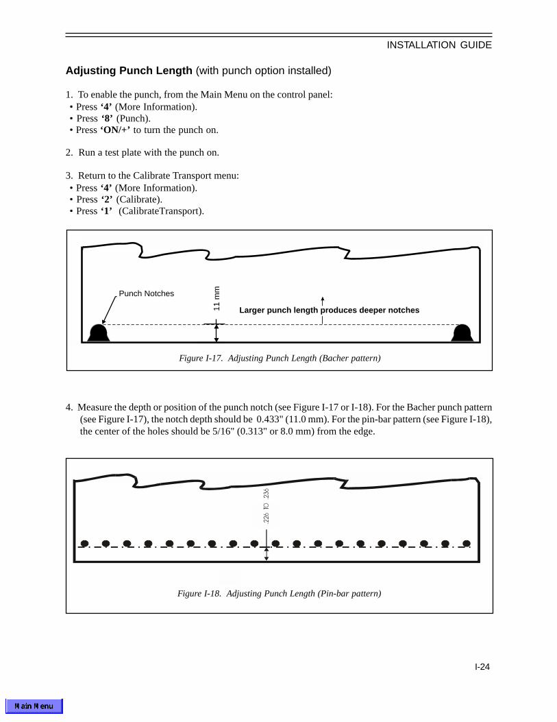
Adjusting Punch Length (with punch option installed)
1. To enable the punch, from the Main Menu on the control panel:• Press ‘4’ (More Information).• Press ‘8’ (Punch).• Press ‘ON/+’ to turn the punch on.
2. Run a test plate with the punch on.
3. Return to the Calibrate Transport menu:• Press ‘4’ (More Information).• Press ‘2’ (Calibrate).• Press ‘1’ (CalibrateTransport).
4. Measure the depth or position of the punch notch (see Figure I-17 or I-18). For the Bacher punch pattern(see Figure I-17), the notch depth should be 0.433" (11.0 mm). For the pin-bar pattern (see Figure I-18),the center of the holes should be 5/16" (0.313" or 8.0 mm) from the edge.
Figure I-17. Adjusting Punch Length (Bacher pattern)
Figure I-18. Adjusting Punch Length (Pin-bar pattern)
Punch Notches
Larger punch length produces deeper notches11 m
m

INSTALLATION GUIDE
I-25
Density-Dot Calibration
See the OPERATOR'S GUIDE, Appendix B, for Density-Dot Calibration procedures.
5. To increase the depth, increase the value for Punch Length Adj and increase Backup Length Adj bythe same amount (there is a separate set of Backup Length values with the punch enabled). Decreasingthe values decreases depth.
6. If necessary, follow the procedure for all resolutions to be used with the punch mode (Punch and BackupLength are set independently for each resolution).

INSTALLATION GUIDE
I-26
De-Installing the PlatesetterThese instructions are provided in the event you ever need to repackage the Platesetter.
1. Turn off the Platesetter and RIP.
2. Disconnect video interface cable from the rear of the Platesetter.
Packaging the Platesetter
A. Package the processor section:
1. Drain processor:Remove the front panel and drain the processor working tanks by removing the overflow tubeslocated inside the Platesetter to the rear of the processor tanks. Catch the effluence in theeffluent tank. Be careful not to allow the tank to overflow.
2. Clean processor:a. Remove cover E.b. Remove guide D. (Press guide towards the front of the Platesetter, lift guide from the rear of
the Platesetter and remove).c. Remove guide F (Press guide towards the rear of the Platesetter, lift guide from the front of the
Platesetter and remove).d. Remove Activator and Stabilizer racks.e. Clean the processor working tanks using warm soapy water.f. Drain and clean the hoses.
3. Package inside of processor:a. Place 2 plated (metal or plastic) Styrofoam pieces in the front (operator side) of the processor
working tanks.b. Place 2 non-plated Styrofoam pieces in the rear (non-operator side) of the working tanks.c. Replace the activator and stabilizer racks, and tape them down.d. Replace Guide D.e. Bubble wrap cover E, guide F and overflow tubes, and tape to the top of the working tanks.
4. Package Carts:a. Remove probes from plastic replenishment containers, air blow dry, and place them in the plastic
clip located up underneath the processor section.b. Empty tanks per local environmental codes.c. Individually bubble wrap the tanks. Place tanks in accessory box.d. Remove (optional) 6' long, 1¼" diameter (180 cm by 3.2 cm) vinyl hose from underneath the
processor. Place in accessory box.

INSTALLATION GUIDE
I-27
B. Package the marker:
1. Disconnect cables:a. Lift the imager top cover.b. Disconnect the grounding strap from the imager section frame.c. Disconnect the 10-wire connector from J6 on the printed circuit assembly (PCA) located on top
of the laser marker assembly.d. Disconnect the ribbon cable(s) from J8 on the PCA and J9 on the PCA.e. Bubble wrap the ends of the disconnected cables.
2. Prepare to remove marker:a. Raise marker by releasing marker lever and lifting the front of the marker.b. Place a 21" by 1" (53 cm by 2.5 cm) piece of tape (black electrical) on the bottom of the laser
marker over the slot for the laser light.c. Detach the strut on the laser end while holding the marker in the upright position and removing
the cap and pulling strut off the ball joint.d. Fasten C shaped black shipping support to the laser (right) end of the marker with eight screws.e. Detach the strut from the galvo (left) end of the marker.f. Reattach cap to struts.
3. Remove marker:a. Place blue plastic bag and two DESI PAK bags in the marker assembly carton, with the bag laid
open.b. Remove the marker from the Platesetter using two people.c. Slide the marker assembly off the brass pivot bushing located furthest from the processor
section (left) without moving the bushing.d. Slide the marker assembly off the brass pivot bushing located closest to the processor (right)
without moving the bushing.
4. Place marker in carton:a. Place the marker assembly in the blue plastic bag, with the laser end placed in the location
shown on the drawing that is attached to the bottom of the carton.b. Fold the blue plastic bag around marker and tie-wrap shut.c. Place flat cardboard cover with the four Styrofoam pieces facing up over the plastic bag. Seal
the carton.d. Bubble wrap and tie wrap the struts inside the Platesetter.

INSTALLATION GUIDE
I-28
C. Package Platesetter:
1. Remove Accessories:a. Remove wire tray located on the right side of the Platesetter. Bubble wrap tray and place in
accessory box. b. Remove customer supplied power plug. Bubble wrap the end of the power cord.c. Remove the media spool assembly. Bubble wrap the media spools, media shaft individually.
Place items in accessory box.
2. Close the Platesetter top cover. Place two DESI PAK bags on the Platesetter crate. Roll thePlatesetter up the ramp onto the Platesetter crate.
3. Support Platesetter off from wheels:a. Place the 18" by 6 3/4" wood block, with lip underneath the bottom front of the imager. The
frame must rest on the foam.b. Place another 18" by 6 3/4" wood block underneath the bottom back of the imager. The frame
must rest on the foam.c. Place the two 24" by 6 3/4" wood blocks underneath the bottom sides of the imager. The frame
must rest on the foam.d. Attach all four wood blocks to the crate by using two wood screws in each block.e. Replace the front & side panels and close the top cover.
4. Plastic-wrap the entire Platesetter. Place the foam cap over the Platesetter. Place the cardboardshipping sides around the Platesetter. Place the ramp inside the foam cap. Place the cardboardcover and sides around the Platesetter. Place ramp on top of the cardboard cover. StrapPlatesetter with ramp to crate. Make sure the ramp, top cover, and sides are very secure.

INSTALLATION GUIDE
I-29
Setup
Cut Length _____
Overlap Length _____
Backup Length (Punch off) _____
Backup Length (Punch on) _____
Punch Length (Punch on) _____
Miniplate Backup Length _____
Image Power (Processor & Mini Plate) _____
MT Speed _____
Serial Numbers:
Component Serial # Model
Imager Unit _________ ____________
Laser Marker Assy _________ ____________
RIP CPU _________ ____________
RIP Monitor _________ ____________
This page should be filled out on Installation.
Serial Numbers and Factory SettingsInstallation Date: ____________________
Location: _________________________
_________________________
_________________________

Operator Manual
700633 Rev B
LEADERS IN COMPUTER TO PLATE
PlateStream SCPlatesetter

COPYRIGHT NOTICE
This manual is copyrighted and all rights are reserved. Under copyright law, this manual may not be copied,by any means or in any form, in whole or in part, without the written consent of Printware.
Printware, Inc., makes no representations or warranties with respect to the contents hereof and specificallydisclaims any implied warranties of merchantability or fitness for any particular purpose. In addition, Printwarereserves the right to revise this publication and to make changes from time to time in the content hereofwithout obligation of Printware to notify any person of such revisions or changes.
© 1998 by Printware, Inc.
IBM and PC are registered trademarks of International Business Machines Corporation.ZipRip, ZAPrip and Printstyle are trademarks of Printware, Inc.Macintosh and AppleTalk are registered trademarks of Apple Computer, Inc.PostScript is a registered trademark of Adobe Systems Incorporated.Futura is a registered trademark of the Fundicion Typografica Neufville SA.Times is a registered trademark of the Linotype Company.Printstyle is licensed to make use of the PostScript® page description language copyrighted by AdobeSystems Inc.
PRINTWARE, INC.1270 Eagan Industrial RoadSt. Paul, MN 55121
Phone: (651) 456-1400
December 1, 2000
The camera-ready master for this manual was generated on a Printware Laser Imaging System and an IBM-compatible PC.

CAUTION! The electronic circuitry inside the Platesetter is very sensitive to damage from electrostaticdischarge (ESD). Always follow the ESD protective procedures described in this manual when workingon the Platesetter.
FEDERAL COMMUNICATIONS COMMISSION (FCC) NOTICEFEDERAL COMMUNICATIONS COMMISSION (FCC) NOTICEFEDERAL COMMUNICATIONS COMMISSION (FCC) NOTICEFEDERAL COMMUNICATIONS COMMISSION (FCC) NOTICEFEDERAL COMMUNICATIONS COMMISSION (FCC) NOTICE
Printware Platesetters generate and use radio frequency. If not installed properly, a Platesetter may causeinterference to radio and television reception.
Printware, Incorporated, complies with the limits for a Class A computing device in accordance with thespecifications in Subpart J of Part 15 of FCC rules. These rules are designed to provide reasonable protectionagainst radio and television interference in a commercial installation.
The user can determine if this equipment is causing interference to radio or television reception by turning thePlatesetter off and on. Listed below are measures the user can take to correct the interference:
a. Reorient the receiving antenna.
b. Relocate the Platesetter with respect to the receiver.
c. Move the Platesetter away from the receiver.
d. Plug the Platesetter into a different outlet so the Platesetter and receiver are on different circuits.
If these measures do not correct the interference problem, the user should consult the dealer or an authorizedtechnician for additional suggestions.
CONTENTS
CONTENTSChapter 1: General Information
Introduction................................................................................ 1-1Features Overview .....................................................................1-4Operator Safety.......................................................................... 1-6
Chapter 2: Control Panel
The Control Panel........................................................................ 2-2Control Panel Menus and Functions.............................................. 2-4
Chapter 3: Preparing for Operation
Preparing to Make Plates............................................................ 3-2Filling the Processor Tanks......................................................... 3-3Loading Plate Media................................................................... 3-5Imaging Plates........................................................................... 3-8MiniPlate Option......................................................................... 3-9
Chapter 4: Operating the Platesetter
Controlling Image Quality............................................................. 4-2Adjusting Exposure .................................................................... 4-2Responding to Control Panel Error Messages................................ 4-3
Chapter 5: Supplies
Introduction................................................................................ 5-2Recommended Consumables...................................................... 5-3Tips on Supplies........................................................................ 5-4

CONTENTS
Chapter 6: Preventive Maintenance
Introduction...............................................................................6-2Maintenance Procedures............................................................6-3
Chapter 7: Troubleshooting
Print Quality Troubleshooting....................................................... 7-2General Troubleshooting.............................................................. 7-7Clearing Media Path .................................................................. 7-10Calling for Service...................................................................... 7-12
Appendix A: Specifications.......................................................... A-2Appendix B: Calibration................................................................ B-2Appendix C: Halftoning and Screening........................................... C-2

1-1
GENERAL INFORMATION
CHAPTER 1
GENERAL INFORMATION
Introduction
The Printware Platesetter is a compact, high resolution digital Platesetter for a range of small-format printing applications. Plates are exposed using a patented laser imaging system, and auto-matically processed. Figure 1-1 illustrates a flowchart of the platemaking process.
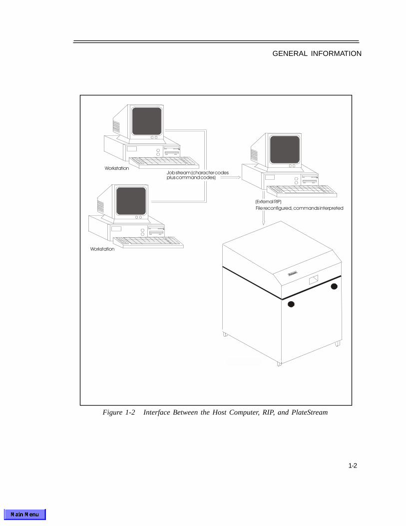
The Platesetter is controlled by a Raster Image Processor (RIP); several different RIP options areavailable, depending on the most common type of work to be done. The system is driven by the hostcomputer on which the operator composes the text and graphics to be imaged. Once the print jobhas been composed on the host computer, it is sent to the RIP, where it is prepared for imaging. Therasterized file is then sent to the Platesetter where the file is imaged onto a plate. Figure 1-2 illus-trates the basic system set-up.
Figure 1-1 Flowchart of the Platemaker Process
1-2
GENERAL INFORMATION
Figure 1-2 Interface Between the Host Computer, RIP, and PlateStream

1-3
GENERAL INFORMATION
Figure 1-3 illustrates the Platesetter media path. It uses a four-step photographic process:
1. Imaging — The laser light beam sweeps across the emulsion side of the plate material as it passesthe laser marker unit. The data generated by the RIP turns the laser on and off. When the laseris turned on, the portion of the plate exposed to the laser sweep is imaged (black); the portions ofthe media not exposed to the laser remain clear/silver.During imaging, the Start Of Scan (SOS) sensor on the marker unit counts the number of scanlines being imaged on the plate, at 2400 scan lines per inch. Once the correct number of scanlines have been imaged, the marker unit keeps the laser turned on to expose the trailing edge ofthe plate.
Once the entire page is imaged the media advances to the cutter. The cutter cuts the media to a specified plate length. After the media is cut, (and punched if the optional punch is installed) it is fed into the integrated processor.
2. Activating (Developing) — a base chemical process which etches the image on the media. Thisis done by the ‘activator’ on silver-halide plate material.
3. Stabilizing (Fixing) — a slightly acidic chemical process which stops the developing. This isdone by the ‘stabilizer’ on silver-halide plate material.
4. Drying — air drying of the processed media. Unless another file is sent immediately, thePlatesetter returns to idle mode. The capstan motors is shut off. The processor transport motorand dryer are also shut off.
Figure 1-3 Media Path of the PlateStream Platesetter
M a rk er L ever
F eed R ollers
M arker
P in ch R oller P in ch R oller
E xit g uid esInp u t gu ide
C ap stan R oller
C utter
O p tion al P u nch
M edia P ath
M edia In pu t S po ol
M edia P ath

1-4
GENERAL INFORMATION
I/O Panel
High Speed
Media Loading
Control Panel
Power Switch
Options
Features Overview
The I/O panel is located on the top rear of the Platesetter. This I/Opanel is used to connect the Platesetter to an external RIP.
The Platesetter images plates at a rate of 40 plates per hour at2400 DPI. Plates emerge right-reading for easy proofing and finalplate checks.The Platesetter can image any width from 9" to 13.3" and anylength from 12" to 22". The maximum roll length is 280'.
The media loading is accessible from the top of the Platesetterproviding quick, easy loading of plate material.
The control panel is an applet on the RIP. The control panel keysallow you to perform a number of adjustment and diagnostic func-tions, and the 8 x 40 character display shows status, error mes-sages, and function menus.
The power switch is located in the rear of the Platesetter.
MiniPlate™—With this option, the Platesetter will impose multiplejobs shorter than the minimum plate length.
Punch—With the PunchStream integrated punch option, thePlatesetter will automatically punch the plate.
Infrared — With this option, the Platesetter will image Infrared(780 nm) plate material.

1-5
GENERAL INFORMATION
Figure 1-4 Features of PlateStream Platesetter
P ow er S w itch
R ear (I/O ) p an el
12 " clearan ce rear
24 " c learan ce r t
30 " c learan ce fron t
47 "
29 " 33 "
12 " clea ran ce le ft

1-6
GENERAL INFORMATION
Operator Safety
The Printware Platesetter has been certified as a Class 1 laser product under the U.S. Departmentof Health and Human Services (DHHS) Radiation Performance Standard.
This standard is in accordance with the Radiation Control for Health and Safety Act of 1968. AClass 1 certification means the Platesetter does not produce hazardous laser radiation.
The laser light produced inside the Platesetter is completely confined within protective housings andexternal covers. The laser beam cannot escape from the Platesetter during any phase of useroperation, provided the user follows the operating instructions specified in this manual. A warninglabel is attached to the bottom of the laser marker unit. This label is visible whenever the media pathhood is open.
The Center of Devices and Radiological Health (CDRH) of the U.S. Food and Drug Administrationimplemented regulations for laser products on August 2, 1976. Compliance is mandatory for prod-ucts marketed in the United States.
Always follow these basic safety rules when using the Printware Platesetter:
1. Read this manual before using the Platesetter.
2. Do not remove protective housings or external covers except as specified in this manual.
3. Do not disassemble the Platesetter or try to repair it yourself, other than as specified in thePreventive Maintenance and Troubleshooting sections of this manual. Call an authorizedservice technician for necessary repair.
4. Plug the power cord into a 3-conductor grounded (earthed) outlet only. Never ground the cord toa gas pipe or a water pipe. Keep the cord away from hot surfaces. Avoid using an extension cord.
5. Use caution when disconnecting any electrical connector within the Platesetter. Do not disconnectelectrical components with the Platesetter turned on.
6. Be extremely careful when working on the Platesetter with the machine turned on and the top coveropen. Notice the warning label attached to the underside of the laser marker unit.
7. Always read and follow all label instructions on supplies carefully. Dispose of used supplies andcontainers appropriately.
8. Use caution when working on or around rollers within the Platesetter with the power on. Beespecially careful when wearing loose-fitting sleeves or a tie. Follow similar precautions whenworking on or around the cutter.

1-7
GENERAL INFORMATION
9. Do not operate the Platesetter if any part of it is damaged, or if any part has been dropped, untilyou have it checked by an authorized service technician.
10. When turning OFF the Power switch, be sure to do it after the machine cycling has cometo a complete stop.
11. Use only supplies designated by Printware with your Platesetter. Consult the recommendedsupplies list that came with your Platesetter system. All supplies should be stored in a cool, dryarea. The use of low grade or improperly stored media will result in print quality problems.
12. There is a lithium battery in the battery-backup RAM on the laser controller board (U17 on522980-XXX), mounted to the top of the laser marker unit. This lithium battery is not replaceable.Dispose of, or recycle, all printed circuit boards properly.
________________________________________________________________________
WARNING! Performing procedures, adjustments, or using controls in a way other than thosespecified in this manual can cause hazardous laser radiation exposure, electrical hazards, or damageto the Platesetter.________________________________________________________________________

2-2
CONTROL PANEL
The Control Panel
The control panel is an applet that runs on the RIP. The control panel program starts automati-cally when the RIP is powered up. Figure 2-1 illustrates a flowchart of the control panel menus.
The panel consists of an 8 x 40 character display which shows status messages and menuoptions, and the following 18 keys:
• an ON/+ key
• an OFF/- key
• an ESC key
• an ENTER key
• 4 arrow keys
• 10 numeric keys, numbered 0-9
These keys allow you to perform a variety of functions. To select an item move the cursor over thecorresponding numeric key with the mouse and push the left mouse button to "press" the key. Toscroll through the choices of the selected item press the ‘ON/+’ or ‘OFF/-’ keys. To changenumbers in a selected item press the numeric keys or press the ‘ON/+’ to increase the number andpress the ‘OFF/-’ to decrease the number. To exit a selected item without saving changes press the‘ESC’ key. To save changes to a selected item press the ‘ENTER’ key. If a key is pressed that hasno effect, the control panel will emit a beep.
The PC keyboard may also be used directly to operate the Control Panel. To minimize the ControlPanel, click on the lower right corner of the Control Panel. This will leave the display, but hide thekeypad. DO NOT close the Control Panel program (upper right corner box) while the imager isoperating - this will cause the interface to crash and the imager to malfunction.
CHAPTER 2

2-3
CONTROL PANEL
P rin tw a re P la teS tre am S C
1 . S e tu p 5 . L o a d2 . Tes t P la te 6 . C u t/F d3 . O n /O ff L in e4 . M o re In fo rm at io nO n L in e - Id le A 0 0 0 0 ’ 2 4 0 0 D PI
P R O C
R u n H ard w are :
1 . T ran sp o rt M o to r : O F F 5 . R ese t P ro c :2 . C u t P la te 6 . S ta rt P ro c :3 . S h u tte r: C lo se 7 . P r im e P u m p :4 . P u n ch P la te :
C a l ib ra te :
1 . C a lib ra te T ran sp o r t2 . C a lib ra te M a rk e r3 . In p u t S p o o l M a n ag e r4 . M ark e r P o si tio n : 0 0 .0 0 "5 . S av e Im a g er Se tu p to R IP6 . L o ad Im ag er S e tu p f ro m R IP7 . E d g e L E D : O F F
C al ib ra te T ran s p ort :
1 . C a lib ra te P ro c es so r2 . M an u a l L en g th A dj : 0 .0 0 0 "3 . C u t L en g th A d j : 1 .9 5 0 "4 . O v er lap L en g th A d j : 0 .7 2 5 "5 . B a ck u p L en g th A dj : 1 .3 5 0 "6 . P u n ch L en g th A d j: 1 .5 0 0 "7 . M in i p la te B a ck u p L en A d j : 0 .0 3 1 "
Te st P la te :
1 . R u n 0 1 P la te s : 2 . C h o o se P a tte rn : C o m p o s ite P a t te rn3 . C h o o se L en g th : 1 3 "O n L in e - Id le A 0 0 0 0 ’ 2 4 0 0 D P I
P R O C
M o re In fo rm a tio n :
1 . R u n H ard w a re 8 . P u n ch : O FF 2 . C a lib ra te 3 . S ta tu s4 . B a ck u p F ee d /T ra n sp o rt5 . M in i p la te C u t L en g th : 1 2 "6 . M in i p la te B a ck u p : O N7 . G u id e B S e n so r : O N
S ta tu s:
1 . S en so r S ta tu s
2 . C u rre n t P la te C o u n t: 0 0 0 1 2 5To ta l P la te C o u n t: 0 01 2 3 4M ate ria l U se d : 0 0 1 2 0 0 '
S e tu p :
1 . Im ag e: N e ga tiv e -R ig h t R ead in g 2 . R e so lu tio n : 2 4 0 0 D P I3 . Im ag e Po w er: 2 54 . M ed ia W id th : 1 3 .12 " (S p o o l P o s : 1 3 )5 . In p u t S p o o l: A6 . D es tin a tio n : P ro ces so r7 . D isp la y U n its : E n g lish
S en so r S ta tu s :
N O M E D IA 0 W R K G N TA N K L O W 0G U ID E B 0 R E P L N TA N K L O W 0 E F F L TA N K H IG H 0 P R O C T E M P L O W 0 P R O C E X IT 0
In p u t Sp o o l M an ag e r:
1 . S p o o l A : 0 0 0 '2 . S p o o l B : 0 0 0 '3 . S p o o l C : 0 0 0 '4 . S p o o l D : 0 0 0 '
Figure 2-1 Control Panel Functional Flowchart

2-4
CONTROL PANEL
1 ON/+
OFF/-
2 3 4 5
6 7 8 9 0
ESC
ENTER
The Power-Up Sequence
When the Platesetter power switch is turned on, the Platesetter performs a sequence of tests of itsinternal components. While the Platesetter is performing these tests, the control panel display willshow a series of status messages indicating the progress of the self-tests. If an error message isdisplayed, correct the error according to the instructions in the Responding to Control PanelError Messages section in Chapter 4. If the display stops at any initialization point for more thantwo minutes, turn off the Platesetter and call for authorized service.
When the power sequence is successfully completed, the display will show the Main Menu screen.
Main Menu
1. Setup – Provides access to the Setup menu.
2. Test Plate – Provides access to the Test Plate menu.
3. On/Off LINE– Sets the Platesetter to either on line or off line. The Platesetter must be online in order to accept print jobs from the RIP. The Platesetter cannot be set to On line if there isan error present. Advancing the display to any of the sub-menus automatically takes thePlatesetter off line.
Printware PlateStream SC
1. Setup 5. Load2. Test Plate 6. Cut/Fd3. On/Off Line4. More InformationOn Line-Transporting A0075' 2400 DPI No MediaLOW PROC TEMP HIGH EFF LOW REPL PROC

2-5
CONTROL PANEL
4. More Information – This selection provides access to several menus.
5. Load – This selection loads the media.
6. Cut/Fd – This selection cuts and feeds the media into the processor for the Miniplate option.
7. The bottom three lines (lines 6-8) of the Main Menu and Test Plate Menu display the currentstate of the Platesetter and any error conditions. Line 5 displays the marker state only if themarker is not ready to print.
Line 5: -- Scan point: 10 = Current marker state, displayed only during a marker error, or while the marker is either calibrating or initializing.
Line 6: -- On/Off Line - Idle = Current imager state, the messages displayed as a single plate is fed through the Platesetter in processor mode are:
On/Off Line – Idle = Imager ready to start imaging, imager andprocessor are idle, except, possibly, for the lastseveral inches of the last plate exiting theprocessor
On/Off Line – Busy = Imager communicating with the RIP
On/Off Line – Backing Up = Backing up leader of plate from cutter to start ofimage point
On/Off Line – Marker Hold = Marker getting ready to image
On/Off Line – Imaging = Imaging current plate
On/Off Line – Image Leader = Imaging leader of next plate
On/Off Line – Advancing = Advancing plate to cutter
On/Off Line – Cutting = Cutting plate
On/Off Line – Punching = Punching Plate
On/Off Line - Transporting = Moving media out of the imager
On/Off Line - Loading = Loading media
On/Off Line - Feeding = Moving media into or through the imager

2-6
CONTROL PANEL
On/Off Line – Ready Pause = 0.5 sec pause between plates
On/Off Line – Ready/Trans = Imager ready to start imaging , plate (s) still inimager
On/Off Line – Ready/Proc = Imager ready to start imaging, plate (s) inprocessor only
A0075' = Approximate number of feet of media left on input spool "A" (if length of media on the spool was entered when the spool was loaded)
2400 dpi = Current resolution (dots per inch)
Line 7:______
NO MEDIA = ‘No media’ detected at sensor closest to input spool
LOW WORKING = Either or both of the processor working tanks are low on chemistry.
INTERLOCK OPEN = The marker is in the raised position
Line 8:______
LOW PROC TEMP = The processor activator bach is not up to specified temperature.
HIGH EFF = The effluent tank is full
LOW REPL = Either or both of the replenisher tanks are empty

2-7
CONTROL PANEL
1. Image — This selection sets the type of imaging for the different types of media. The choicesare: Positive or Negative Wrong Reading, and Positive or Negative Right Reading.
PROC = Imager is in processor mode
MINI = Imager is in miniplate mode, there are No accumulated miniplates in theimager
MINI3 = Imager is in miniplate mode, there are 3 accumulated miniplates in theimager (if there are more than 9 accumulated miniplates, the digitchanges to a ‘+’ )
PROC = Imager destination (lower right corner of operator panel):
1 ON/+
OFF/-
2 3 4 5
6 7 8 9 0
ESC
ENTER
Setup Menu
Setup: [ESC to exit]
1. Image: Negative-Right Reading 2. Resolution: 2400 DPI 3. Image Power: 25 4. Media Width: 13.12" (Spool Pos: 13) 5. Input Spool: A 6. Destination: Processor 7. Display Units: English

2-8
CONTROL PANEL
2. Resolution — Sets the resolution of plates imaged from the control panel. The PlateStream SCruns at 2400 dpi.
3. Image Power — Sets the image power (laser intensity). Increasing image power increasesD
max or Density, while decreasing image power reduces D
max.
4. Media Width: xx.xx" (Spool Pos: yy) — Media Width is the exact width, entered by theoperator, from 7.00" to 13.40" (17.78 cm to 34.00 cm). Spool Pos is automatically calculated fromMedia Width, and indicates the position to set the spool or cassette. Spool position is set at the mediawidth in inches, rounded to the nearest inch, from 7 to 13. Media Width is set independently for eachof the Input Spools (see #5 below), eliminating the need to reset image width every time the spoolis changed.
5. Input Spool — Selects the input spool. The choices are: A, B, C, or D. The media remainingfor the selected spool decreases as media is imaged (see Spool Manager later in this chapter).Each spool can hold up to 280' (85 m); each spool’s counter can be reset after reloading. Inputspool selection will be displayed in front of the feet remaining in the main menu.
6. Destination — Sets the output destination for the imaged media. Choices are: ‘Processor,’ or‘Processor Miniplate’ with the Miniplate option. For a standard PlateStream SC with no optionsinstalled, Processor is the only destination.
7. Display Units – Toggles between English and Metric display units.
NOTE: This manual generally refers to English display units with Metric units in parentheseswhere applicable.

2-9
CONTROL PANEL
Test Plate Menu
1. Run nn Plates — Sets the number of plates from 1 to 99.Pressing ENTER sets the specified number of plates to be printed. Pressing ENTER again causesthe specified number of plates to be printed. As each plate is printed, the displayed number willdecrement by 1. Printing can be interrupted by pressing the ESC key. If printing is interrupted, thecurrent plate will be imaged, the Platesetter will not print the remaining plates, the displayed numberwill return to its selected value. If printing is not interrupted, then once the specified number ofplates have been imaged the displayed value will return to its selected value.
2. Choose Pattern — This selection sets the pattern. The choices are:
Composite Pttrn Large Black SqsAll White Plate Large White SqsAll Black Plate Light Gray ToneHalf Blk/Wht Dary Gray ToneThin Vert Lines Horz Line ResWide Vert Lines Press PatternThin Horiz ScreenWide Horiz Calib ScreenSmall Black Sqs 4 Pix on FocusSmall White Sqs
3. Choose Length — Sets the length of the test plate. The allowable range is 12" to 22" inprocessor mode, and 2" to 22" in Miniplate modes.
1 ON/+
OFF/-
2 3 4 5
6 7 8 9 0
ESC
ENTER
Test Plate: [ESC to exit]
1. Run 01 Plates2. Choose Pattern: Composite Pattern3. Choose Length: 13"On Line - Transporting A0000' 2400 DPI
PROC

2-10
CONTROL PANEL
1. Run Hardware — Provides access to the Run Hardware menu.
2. Calibrate — Provides access to the Calibrate menu.
3. Status — Provides access to the Status menu.
4. Backup Feed/Transport — Turns the capstan motor on and backs up the media six inches.This is used to clear media wrapped around the capstan roller (see Clearing Media Path inchapter seven). To stop capstan motor, press ‘ESC’ or ‘OFF/-’ key.
5. Miniplate Cut Length:—(Only with Miniplate option installed) Cuts the plate if accumulatedMiniplate length exceeds this value. Values are integer inches, e.g., 12", 13", 14", 15", 16", 17", or18". The 18" setting cuts all plates greater than 17.5". The minimum cut length is 12". The maxi-mum cut length is 18".
6. Miniplate Backup:—Enables calibration or elimination of the gap between jobs in Miniplate mode(see Physical Calibration in the INSTALLATION GUIDE).
7. Guide B: Turns the Guide B sensor On/OFF. The sensor should be ON to detect jams unlessthe sensor is damaged.
8. Punch:—(Only if punch option installed) turns the punch on and off.
More Information Menu
1 ON/+
OFF/-
2 3 4 5
6 7 8 9 0
ESC
ENTER
More Information [ESC to exit]
1. Run Hardware 8. Punch: OFF2. Calibrate3. Status4. Backup Transport5. Miniplate Cut Length: 12"6. Miniplate Backup: ON7. Guide B Sensor: ON

2-11
CONTROL PANEL
1. Transport motor — Turns on or off the capstan motor.
2. Cut Plate — Cycles the cutter.
3. Shutter — Opens and closes the shutter.
4. Punch Plate — Cycles the Punch
5. Reset Proc — Stops the processor and resets all of the counters.
6. Start Proc — Starts the processor to test for functionality of this section.
7. Prime pump — Turns on the processor pump for approximately five minutes.
1 ON/+
OFF/-
2 3 4 5
6 7 8 9 0
ESC
ENTER
Run Hardware: [ESC to exit]
1. Transport Motor OFF 5. Reset Proc:2. Cut Plate: 6. Start Proc:3. Shutter: Close 7. Prime Pump:4. Punch Plate:
Run Hardware Menu

2-12
CONTROL PANEL
1 ON/+
OFF/-
2 3 4 5
6 7 8 9 0
ESC
ENTER
Calibrate: [ESC to exit]
1. Calibrate Transport2. Calibrate Marker3. Input Spool Manager4. Marker Position: 00.00"5. Save Imager Setup to RIP6. Load Imager Setup from RIP7. Edge LED: OFF
Calibrate Menu
1. Calibrate Transport—Provides access to the Calibrate Transport menu.
2. Calibrate Marker—Sets the marker to perform a full calibration the next time the machine ispowered up.
3. Input Spool Manager—Provides access to the Spool Manager menu.
4. Marker Position—Adjusts the side-to-side image position up to +0.05" (+0.13 cm) (Increas-ing the value moves the imager away from the operator side, decreasing the value moves theimager towards the operator side) to accommodate the physical position of the marker.
5. Save Imager Setup to RIP—Saves the imager setup data to the RIP hard drive.
6. Load Imager Setup from RIP—Reloads the imager setup data from the RIP hard drive.
7. Edge LED:—(Only if 34cm option installed) turns on the Edge Fogging LED, which exposesapproximately 0.2" on the operator side of the plate. The Edge LED should normally be OFF for platewidths of 13.3" or less, and ON for plate widths more than 13.3", allowing a fully-exposed 13.4" plate.

2-13
CONTROL PANEL
1 ON/+
OFF/-
2 3 4 5
6 7 8 9 0
ESC
ENTER
Calibrate Transport Menu
Calibrate Transport: [ESC to exit]
1. Calibrate Processor2. Manual Length Adj: 0.000"3. Cut Length Adj: 1.950"4. Overlap Length Adj: 0.750"5. Backup Length Adj: 1.350"6. Punch Length Adj: 1.500"7. Miniplate Backup Len Adj: 0.134"
1. Calibrate Processor — Runs a plate which calibrates the processor exit sensor for 2400 dpi.The processor exit sensor is calibrated at the factory. If the control panel error displays ‘Mediadidn't exit imager’ or ‘Media didn't exit processor’ calibrating the processor is one of the possiblesolutions. Ensure that destination is set to “Processor,” then Calibrate the processor by pressing‘ENTER’. The Plateseetter must be in Processor mode to calibrate the processor.
For more details on menu items 2 - 7, see Physical Calibration in the INSTALLATION GUIDE.
2. Manual Length Adj: — Incremental corrections to obtain the correct plate length. The lengthchange displayed is reset to ‘0’ after pressing enter. At 2400 dpi, the manual length is adjustable in0.002" (0.005 cm) increments. The length will not be changed if the increment entered is less thanthe minimum increment size.
3. Cut Length Adj:—Sets the length of the trailing edge of the plate.
4. Overlap Length Adj:—Sets the length of plate that is double exposed on the leading edge.
5. Backup Length Adj:—Adjusts the length of the leader (there is a second set of values with thepunch option installed).
6. Punch Length Adj:—(Only with the punch option installed) Adjusts the punch position on theplate.
7. Miniplate Backup Length Adj:—(Only with the Miniplate option installed) Calibrates orelimi-nates the gap between jobs in Miniplate mode.

2-14
CONTROL PANEL
1 ON/+
OFF/-
2 3 4 5
6 7 8 9 0
ESC
ENTER
1 ON/+
OFF/-
2 3 4 5
6 7 8 9 0
ESC
ENTER
Input Spool Manager [ESC to exit]
1. Spool A: 0280'2. Spool B: 0280'3. Spool C: 0280'4. Spool D: 0280'
Input Spool Manager Menu
1. Spool A: — Sets the amount of material in spool A (up to 280' or 85 m).
2. Spool B: — Sets the amount of material in spool B.
3. Spool C: — Sets the amount of material in spool C.
4. Spool D: — Sets the amount of material in spool D.
Status Menu
Status: [ESC to exit]
1.Sensor Status
2.Current Plate Count: 000000 Total Plate Count: 000000 Material Used: 000000
1. Sensor Status — This selection provides access to the Sensor Status menu.
2. Current Plate Count — This selection clears and displays the current plate count.
Total Plate Count — Displays the total number of plates imaged by the Platesetter.
Material — Displays the total number of feet of material run through the Platesetter.

2-15
CONTROL PANEL
1 ON/+
OFF/-
2 3 4 5
6 7 8 9 0
ESC
ENTER
Sensor Status Menu
SENSOR STATUS: [ESC to exit]NO MEDIA 0 WRKNG TANK LOW 0GUIDE B 0 REPLN TANK LOW 1
EFFL TANK HIGH 1PROC TEMP LOW 0PROC EXIT 0
The Sensor Status menu indicates the current digital status of all Platesetter sensors. Explanationsof all the sensor indications are shown below. This menu is provided primarily for trained techni-cian use.
NO MEDIA — Identifies the amount of media in the spool as okay or none. A ‘0’ indicates thatthe media supply is empty, ‘1’ indicates that the amount is sufficient.
REPLN TANK LOW — This sensor monitors the solution level in the replenishment tanks. A‘0’ indicates the current level is okay; a ‘1’ indicates a low solution level in one or both of the tanks.
EFL TANK HIGH — This sensor monitors the level of spent solution in the effluent tank. A ‘0’indicates the current level is okay; a ‘1’ indicates the tank needs to be emptied.
PROC TEMP OK — The processor Activator Temperature sensor monitors the temperature ofthe Activator bath. A ‘0’ indicates that the current temperature is okay; a ‘1’ indicates that thebath is still warming up, or that there is a problem with the heater.
PROC EXIT — Indicates the presence or absence of media at the processor exit sensor. A ‘1’indicates that media is present (e.g., during imaging). A ‘0’ indicates the sensor is clear. This isthe normal operating condition.
GUIDE B — Indicates the presence of media at Guide B. A ‘1’ indicates that media is present(e.g., during imaging). A ‘0’ indicates the sensor is clear. This is the normal idle condition.
WRKNG TANK LOW — This sensor monitors the chemistry level in the working tanks in theprocessor. A ‘0’ indicates the current level is okay; a ‘1’ indicates a low solution level in one or bothof the tanks.

3-1
PREPARING FOR OPERATION

3-2
PREPARING FOR OPERATION
Preparing to Make Plates
Overview
The following information explains how to prepare the Platesetter for a print job. Refer to your hostcomputer operator manual and the RIP operator manual for further detail on connecting and operatingthese devices with the Platesetter.
Introduction
Before making a plate, the Platesetter must be:
• Loaded with the correct type of plate media (see Loading Plate Media section in this chapter).
• Connected to the RIP; I/O panel is located on the top rear of the machine.
• Ready to accept a print job (Main Menu displayed on the control panel, On-Line state, no error conditions).
• The integrated processor must be filled to proper levels (see Filling the Processor Tanks section in this chapter).
CHAPTER 3

3-3
PREPARING FOR OPERATION
Filling the Processor Tanks
Overview
Fill the processor working tanks and replenishment tanks as needed. Follow manufacturer's safetyinstructions. The message ‘LOW REPL’ will appear on the lower half of the control panel MainMenu when one or both of the replenishment tanks are low on chemistry. The message ‘LOWWORKING’ will appear on the lower half of the control panel Main Menu when one or both of theprocessor working tanks are low on chemistry. The message ‘HIGH EFF’ will appear on the lowerhalf of the control panel Main Menu when the effluent tanks is full. Once per week, clean theprocessor racks. Follow the cleaning procedure as described in Chapter 6, Preventive Mainte-nance.
Procedure
1. Remove imager front panel and remove cover E from processor. (See figure 3-1).
2. If necessary, prepare the Activator and Stabilizer solutions in the plastic replenishment containersfollowing the manufacturer's instructions.
3. Remove probes from the replenishment containers. Fill the processor working tanks inside thePlatesetter and the replenishment containers with the proper chemistry. Reinstall the probesinto the replenishment containers. Make sure the activator tanks are filled with activator and thestabilizer tanks are filled with stabilizer. Place cover E over processor working tanks. Replacefront panel.
4. Remove the probe and hose from the effluent tank. Remove the effluent tank and empty it. Besure to dispose of or recycle the spent chemistry in accordance with local regulations.
5. Reinstall the probe and hose into the effluent tank. Reinstall the effluent tank. Replace the frontpanel.

3-4
PREPARING FOR OPERATION
Note: If the processor has not been in use for several days, the racks can freeze up due to evapo-ration causing rollers to stick together. The racks should be removed and rinsed with water androtate the gears to free them up. Failure to do so can result in gear breakage.
Figure 3-1 Side View of the PlateStream Platesetter Processor
M a rk er L ever
F eed R o ller s
M ark er
P in ch R oller P in ch R oller
E x it gu id e sIn p u t gu id e
C a p stan R o ller
C u tter
O p tion a l P u n ch
M ed ia P ath
M ed ia In p u t S p o o l
M ed ia P ath
P ro cessor W o rk in gTa n k s
A c tiva to rTa n k
S tab ilizerTa n k
D r ye rS ection

3-5
PREPARING FOR OPERATION
Loading Plate Media1. Open the top cover. Raise the marker by pulling the marker lever up until lever stops. Lift up on the
marker gently. (See Figure 3-1). If you are replacing the roll of plate media, the last segment of theprevious roll may need to be removed from the platesetter.
2. Remove the spool assembly from the Platesetter.
3. Adjust the rear edge guide inside the Platesetter by pulling the edge guide knobs up and sliding to theposition closest to the plate media width. Adjust the front edge guides by loosening the screw andmoving the guide all the way to the front.
4. Adjust the left hub on the spool shaft to match the edge guide position by squeezing the clip andsliding on shaft. Remove the right hub from the shaft by lifting clip and sliding off the shaft. Slidemedia onto shaft. Slide the right hub onto shaft by lifting clip and pushing down on spool until spoolis tight against media (see Figure 3-3).
5. Place the spool assembly on the receptacles in the Platesetter. Feed media through rollers and twoedge guides. Adjust the front edge guide by turning edge guide knobs counterclockwise and slidingedge guide until edge guide rests against plate media. Lock edge guide by turning knobs clockwise.Feed the media by hand up to the nip of the capstan roller and engage (hold down) the load switchfor approximately 5 seconds. Watch so that the feed side of the capstan roller picks up on the mediaand begins to transport it. After the media has fed past the exit side pinch roller, release the loadswitch. Manually turn the exit side pinch roller approximately 2 turns counterclockwise to removethe loop, which may have formed over the capstan roller during the load. This last step will help theregistration of the first few plates output from the platesetter after this load sequence as comparedwith previously processed plates or ones that may be processed later.
6. Gently lower the marker and lock down by pushing the marker lever down until the lever is horizontal. Close the top cover.
7. Set the plate width from the control panel setup menu. Load media from the control panel. Image one test plate from the control panel Test Plate menu.

3-6
PREPARING FOR OPERATION
NOTES:
• Cut off any punched area of plate before reloading to ensure a reliable load.
• Remove leader from daylight load media before loading media.
• Media must be loaded with no tears or wrinkles.
• Media must be reloaded after jams or other fault conditions. In this case, a message will appear on the operator panel to “Reload Media” or “Manually Reload Media.”
• The (Optional) Edge LED should be ON for plate widths more than 13.3", allowing a fully-exposed 13.4" plate (see chapter 2 in the section More Information Menu).

3-7
PREPARING FOR OPERATION
Figure 3-2 Location of Spool Assembly
Figure 3-3 Loading Plate Media on Spool
Spool A ssem bly
R ecepta cle

3-8
PREPARING FOR OPERATION
Imaging Plates
1. Configure RIP; Connect to the Network
ZAPripHQ (Harlequin/Xitron) RIPa. Press ctrl-alt-del to log on.b. Log in as Administrator with password: printware.c. Double-click on the ZAPrip icon.d. Choose Start Inputs from the Xitron RIP menu to start the RIP.
2. Print a Joba. Be sure your front-end computer can see the network hot folder.b. The ZAPrip HQ (Harlequin) RIP can use the Mac chooser as well as a hot
folder. To set this up, use the chooser to select the desired PlateStream outputdevice and resolution.
c. If a print driver is required, use Adobe 4.2 for WIN95/98, Adobe 5 for NT.d. Create a test job whose document size is equal to the desired plate size.e. Print the job, saving it as a PostScript file in the spool (“hot”) folder (or using the
print command if using set up with Mac chooser).

3-9
PREPARING FOR OPERATION
1 ON/+
OFF/-
2 3 4 5
6 7 8 9 0
ESC
ENTER
MiniPlate™ Option
With the MiniPlate option, the Platesetter accommodates jobs shorter than the 12" minimum platelength by imposing several small jobs down the length of a plate. To turn MiniPlate on, change thedestination to Processor MiniPlate in the Setup Menu (see chapter 2 in the section Setup Menu).The minimum job length is 1". MiniPlate accumulates shorter jobs until the combined length of thejobs exceeds an operator-selected cut length (e.g., 12"). The plate material is then cut and runthrough the processor. MiniPlate cut length can be set from 12" to 18" in the More Information Menu(see chapter 2). The gap between jobs in MiniPlate Mode can be eliminated or set to a desiredamount in the Calibrate Menu (see the Physical Calibration section of the INSTALLATION GUIDE).This calibration is enabled in the More Information Menu.
The CUT/Fd key ‘6’ operation will cut and feed into the processor any MiniPlates remaining in thePlatesetter. The extra material fed to bring the length up to the selected minimum length will beimaged black so as not to pick up ink on the press. The word ‘MINI’ in the lower right corner of themain menu indicates that the Platesetter contains MiniPlates that have not been cut or processed.The following digit indicates the number of MiniPlates in the Platesetter, and if more than 9 MiniPlatesare present the digit will be replaced by a ‘+’.
Printware PlateStream
1. Setup 5. Load2. Test Plate 6. Cut/Fd3. On/Off Line4. More InformationOn Line - Transporting A0075" 1800 DPI
MINI3

4-2
OPERATING THE PLATESETTER
CHAPTER 4
OPERATING THE PLATESETTER
Making a Plate
Controlling Image QualityTo maintain optimum print quality, use only recommended media and processing chemistry, andstore all supplies properly. Also, perform the preventive maintenance procedures detailed in Chap-ter 6 to keep the Platesetter clean and in proper operating condition. Be sure all Platesetter coversare completely closed when making plates.
Once per week (or more often if conditions require) print a test plate and inspect the print quality. Ifimage quality problems are noticed, perform the following adjustments. Image quality problemsmay include slight changes in character stroke width, image density, or background density.
Refer to your RIP reference guide for instructions on printing a test plate. Inspect the plate. Ifimage quality problems are found, adjust the exposure as described in the next section.
Adjusting Exposure (Laser Intensity)
See CALIBRATION in Appendix B
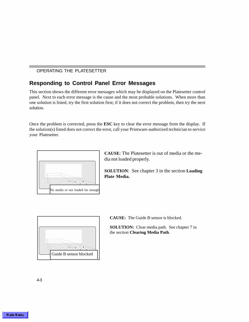
4-3
OPERATING THE PLATESETTER
Responding to Control Panel Error MessagesThis section shows the different error messages which may be displayed on the Platesetter controlpanel. Next to each error message is the cause and the most probable solutions. When more thanone solution is listed, try the first solution first; if it does not correct the problem, then try the nextsolution.
Once the problem is corrected, press the ESC key to clear the error message from the display. Ifthe solution(s) listed does not correct the error, call your Printware-authorized technician to serviceyour Platesetter.
1 ON/+
OFF/-
2 3 4 5
6 7 8 9 0
ESC
CAUSE: The Platesetter is out of media or the me-dia not loaded properly.
SOLUTION: See chapter 3 in the section LoadingPlate Media.
No media or not loaded far enough
1 ON/+
OFF/-
2 3 4 5
6 7 8 9 0
ESC
Guide B sensor blocked
CAUSE: The Guide B sensor is blocked.
SOLUTION: Clear media path. See chapter 7 inthe section Clearing Media Path.

4-4
OPERATING THE PLATESETTER
SOLUTION: Clear media path. See chapter 7 inthe section Clearing Media Path.
CAUSE: The leading edge of the media was notdetected by the Guide B sensor within the expectedamount of time.
1 ON/+
OFF/-
2 3 4 5
6 7 8 9 0
ESC
Media didn't enter Guide B
1 ON/+
OFF/-
2 3 4 5
6 7 8 9 0
ESC
Processor exit sensor blocked
1 ON/+
OFF/-
2 3 4 5
6 7 8 9 0
ESC
Media didn't exit processor
CAUSE: The sensor under cover Gis blocked.
SOLUTION: Clear media path. Seechapter 7 in section Clearing MediaPath.
CAUSE: The leading edge of the me-dia was not detected by the processorexit sensor within the expected amountof time.
SOLUTION:1. Clear media path. See chapter 7 insection Clearing Media Path.
2. Calibrate the processor. See chap-ter 2 in the section Calibrate Menu.

4-5
OPERATING THE PLATESETTER
CAUSE: The Platesetter electronics have detecteda problem with one of the power supply voltagelevels during power up.
SOLUTION: Turn off the Imager and call forservice.
CAUSE: A print job was sent to the Platesetterwhile it was not in the On Line state.
SOLUTION: From the Main Menu on the controlpanel, press 3 to return the Platesetter to the OnLine state.
1 ON/+
OFF/-
2 3 4 5
6 7 8 9 0
ESC
1 ON/+
OFF/-
2 3 4 5
6 7 8 9 0
ESC
Power out of spec detected
1 ON/+
OFF/-
2 3 4 5
6 7 8 9 0
ESC
RIP requesting to image plate
Scan initialization time-out
Cause: The marker unit did not power up cor-rectly within the expected time.
SOLUTION:
1. Turn the Platesetter off, wait 30 seconds,turn the Platesetter back on and wait for thepower up to be completed.
2. Call for service

4-6
OPERATING THE PLATESETTER
1 ON/+
OFF/-
2 3 4 5
6 7 8 9 0
ESC
Marker not ready!
CAUSE: The marker is not ready to image.
SOLUTION:
1. Turn the Platesetter off, wait 30 seconds, turnthe Platesetter back on and wait for the power upto be completed.
2. Call for service.

5-1
SUPPLIES

5-2
SUPPLIES
CHAPTER 5
SUPPLIES
Introduction
Using recommended supplies ensures high quality printing plates and printed output. The Plateset-ter is designed to image silver halide-coated plate material. Silver-halide material is normally imagednegative right reading (see chapter 2 in the section Setup Menu). Plate media may be either paperor polyester based. Roll width may be from 7" to 13.4" (17.8 cm to 34 cm). The maximum rolllength is 280' (85 M).

5-3
SUPPLIES
RECOMMENDED CONSUMABLES FOR PLATESTREAM SC
PRINTWARE: SILVERSTREAM+
RED LIGHT PLATE MEDIA:
Emulsion In
5 mil polyester 808555-XXX (280 FT ROLLS)8 mil polyester 808666-XXX (280 FT ROLLS)
(Note: -XXX specifies the specific roll width from 7" to 13.4")
CHEMISTRY:ACTIVATOR: 808777-001STABILIZER: 808777-002

5-4
SUPPLIES
Tips on Supplies
To get the best performance from your Platesetter, follow these guidelines for storing and handlingsupplies.
Plate Media
•Handle imaging media by the ends.
•Avoid excessive touching of the surface of the media.
•Store media rolls upright (on end), not on their sides.
•To prevent the crushing of media, avoid placing other objects on top of the media rolls.
•Store all media as recommended by the manufacturer.
•Plate material will absorb moisture in humid environments and lose moisture in dry environments,which will affect print quality. However, the plate material may not be permanently damaged.Improperly stored plate material will recover if stored for an extended period with the bag openin ideal humidity conditions.
•For optimum print quality, use only recommended media.
•Do not load media that is wrinkled or torn.
Processing Chemistry
•Use only recommended processing chemistry.
•Carefully follow all label instructions for mixing and use.
• After use, recap activator and stabilizer solution bottles tightly.
•Store all chemicals in a well-ventilated area. Follow the manufacturer’s instructions regardingsafety, storage, temperature, humidity, and other environmental factors.
•Rotate supplies to use the oldest items first.
•Disposal of all chemicals must meet local environmental codes.

6-2
PREVENTIVE MAINTENANCE
CHAPTER 6
PREVENTIVE MAINTENANCE
Introduction
To avoid problems with the Platesetter, maintain high print quality, and to avoid unnecessary servicecalls follow the instructions in this chapter.
• Keep all equipment clean and well maintained.
• Perform regularly scheduled preventive maintenance.
• Carefully follow instructions for the mix and use of chemistry. Ink and press chemistry must becompatible.
• Keep all solutions filled to the proper levels.
• Handle plate media carefully.
• Mount plates on the press properly.
Operator Maintenance Schedule
1. Follow the "Printware Recommended Periodic Maintenance Schedule" in the Service manual.

6-3
PREVENTIVE MAINTENANCE
Maintenance Procedures
Cleaning the Imager Rollers
Clean all the Imager capstan rollers when necessary to prevent plate slippage or plate skew. It’seasiest to clean the rollers just after the spool has run out of media. To clean these rollers:
1. Open the top cover. Raise the marker by pulling marker lever up until lever stops. Lift up markergently (see Figure 6-1).
Figure 6-1 Side View of the PlateStream Platesetter
M arker L eve r
Feed R ollers
M arker
Pinch R oller Pinch R oller
Exit guide BInput guide A
C apstan R oller
C utter
O ptiona l Punch
M e dia Path
M e dia Input Spoo l
M e dia Path
Exit guide C
C over E
C over E
G uide F
Processor WorkingTanks
A ctivatorTank
StabilizerTank
D ryerSection

6-4
PREVENTIVE MAINTENANCE
**********************************************************************************CAUTION! Be very careful when working on or around the Imager rollers with the machinerunning, especially when wearing a tie or loose-fitting sleeves, to avoid getting anything caughtbetween the rollers.**********************************************************************************
2 . From the Main Menu display on the control panel, press ‘4’ and then ‘1’ to access the RunHardware Menu.
3. Turn on the capstan motor by pressing the ‘2’ key and then the ‘ON/+’ key. Access the rollersfrom the top of the Platesetter and open the shutter. As the pinch and capstan rollers arerotating, clean them using a soft cloth and D-Ink. Press the ‘OFF/-’ key to turn off the transportmotor, then press ‘ESC’.
4. Press the ‘ESC’ key again to return to the Main Menu, then press the ‘3’ key to return thePlatesetter to the on-line mode.
5. Gently lower the marker and lock by pushing marker lever down until lever is horizontal. Close the top cover.
6-5
PREVENTIVE MAINTENANCE
For optimum performance of the processor module, it is important to keep all chemistry filled to theproper levels, and clean the machine weekly to prevent a buildup of chemistry on the rollers. Theprocessor should be cleaned more frequently if needed to maintain plate quality. If you're usingMitsubishi Silver Digiplate, the processor should be cleaned if the pH of the chemicals fall outsidethe recommended range:
Activator: pH > 12.8Stabilizer: pH < 6.8
To clean the processor (see figure 6-1):
1. Open the top cover. Be sure that the effluent tank is empty before beginning this procedure. Placethe effluent drain hose from underneath the processor into the effluent tank. Drain the processorworking tanks by removing the overflow tubes located in the rear of the processor tanks inside thePlatesetter.
2. Remove cover E. Remove guide F by pressing guide towards the back of the Platesetter, lift guidefrom the front of the Platesetter and remove. Wash cover E, and guide F, in warm soapy water
and dry using a soft cloth.
3. Remove Activator and Stabilizer racks. Clean the processor working tanks using warm soapywater, and dry with soft cloth. Clean Activator and Stabilizer racks using warm soapy water.Rotate the rollers and clean them using a soft cloth and warm soapy water. Replace the Activatorand Stabilizer racks to original positions. Replace guides and cover to original position.
4. Remove cover G. Remove dryer rack by holding the metal edge in the center of the dryer rack,lift to clear the two bottom pins, and remove. Wash cover G and dryer rack in warm soapy waterand dry using a soft cloth. Replace dryer rack and cover G to original position.
5. Close top cover.
Cleaning the Processor Module

7-2
IN CASE OF TROUBLE
CHAPTER 7
TROUBLESHOOTING
Print Quality Troubleshooting
PROBLEM CAUSE SOLUTION
‘Scumming’ (ghostimages, smudges orblotches on prints dueto poor plate surface)
1 The press ink/fountainbalance is incorrect.
2. The press fountain mix-ture is incorrect or tooweak.
3. The press ink is not com-patible with the otherchemicals.
4. The press dampenerform roll pressure is outof adjustment.
5. The press Moleton coveror sleeve is contami-nated.
1. Correct the balance.
2. Use the recommended fountain solution,properly mixed.
3. Use the recommended ink.
4. Adjust the pressure.
5. Replace the cover or sleeve.
6. The Platesetter Processor chemistry is depleted.
6. Replace Platesetter Processor chemistry.

7-3
IN CASE OF TROUBLE
PROBLEM CAUSE SOLUTION
Image Binding (faintreproduction)
1. The press ink/fountain bal-ance is incorrect.
2. The press pressure is insuf-ficient.
3 The press ink rollers areglazed.
4. The paper is clinging to thepress blanket.
5. The press fountain concen-tration is too strong.
6. The press blanket was notdry on roll-up.
7. The press blanket is glazed.
1. Check the balance and correctif necessary.
2 Check the pressure and cor-rect if necessary.
3. Deglaze the rollers.
4. Check the paper supply andclean the blanket.
5. Replace with correct concen-tration.
6. Allow the blanket to dry be-fore roll-up.
7. Deglaze the blanket.

7-4
IN CASE OF TROUBLE
1. The press fountain concentra-tion or ink is incorrect.
2. The press ink/fountain balanceis incorrect.
3. The press rollers or blanket isglazed.
4. Press pressure is insufficient.
1. Exposure (laser intensity) is settoo high.
1. Platesetter processor chemistryis dirty.
2. Laser is out of focus.
1. The Platesetter rollers are dirty.
2. Bad plate material.
3. Platesetter processor chemistry is dirty.
Slow Roll-up or PoorInk Transfer
Weak or Uneven Image(lose fine lines,pinholes in solids)
Fuzzy or Blurry Image
Marks on Plate orScratched Plates
PROBLEM CAUSE SOLUTION
1 Check and replace if necessary.
2 Check the balance and correct if neces-sary.
3. Deglaze the rollers or blanket.
4. Check the pressure and adjust if neces- sary.
1. Adjust the exposure in the PlatesetterSetup menu on the control panel perplate Media Manufacturer's instruc-tions.
1. Clean processor and replace processorchemistry.
2. Call for service.
1. Clean the Platesetter rollers.
2. Replace the plate material.
3. Replace processor chemistry.

7-5
IN CASE OF TROUBLE
Plugged Images orExcessive Back-ground
Wrinkled/CrackedPlates
Plates have ShortPress Life
1. The exposure is set toohigh.
2. Bad plate material.
1. The press plate clamp isimproperly set.
1. Press pressure is exces-sive.
2. Press blanket surface is tooharsh.
3. There are abrasive particlesin the press ink.
4. The press ink/fountain balance is incorrect.
5. The press ink is too tacky.
1. Adjust the exposure using thePlatesetter Setup menu on thecontrol panel.
2. Replace plate material.
1. Check handling techniqueswhen mounting plates, andcheck the uniformity of theplate clamp.
1. Adjust the pressure.
2. Change to a softer, smootherblanket.
3. Replace the ink.
4. Adjust the moisture control onthe press to minimum.
5. Replace the ink or add reducer.
6. Change Processor chemistry.
7. Call for service.
PROBLEM CAUSE SOLUTION
6. Platesetter Processor chemistry is depleted.
7. Marker out of focus.

7-6
IN CASE OF TROUBLE
PROBLEM CAUSE SOLUTIONToning/Specking(Background)
Smeared Images,"Tails" on Charac-ters
Weak Image onPress
1. Plate media has abrasions.
2. The press ink is emulsified.
3. The press fountain solution iscontaminated.
4. The Platesetter rollers aredirty.
5. Platesetter Processor chemistry is weak.
1. Plate media defective/incom-patible.
2. Too much press ink.
1. The press fountain solution iscontaminated.
2. The roller pressure on thepress is incorrect.
1. Handle plate media more carefully.
2. Change the fountain solution andthe ink.
3. Change the fountain solution. Useonly distilled water for preparingsolution.
4. Clean the rollers.
5. Change processor chemistry.
1. Change plate media.
2. Clean up press and reduce ink.
1. Replace the fountain solution. Besure to use distilled or deionizedwater for preparing the solution.
2. Check the stripes (pressure be-tween the press rollers).
7-7
IN CASE OF TROUBLE
General Troubleshooting
PROBLEM SOLUTION
The Platesetter will notTurn ON (No Power)
Platesetter will not Start aPrint Job
“Reload Media” or“Manually Reload Media”message; Platesetter willnot Start a Print Job
1. Ensure that the Platesetter is plugged in.
2. Check the fuse or breaker for the outlet. Try unplugging thePlatesetter and plugging another electrical item into the outletto be sure that it has power.
1. The Platesetter may not have completed its power-up sequence.When the Platesetter is ready, the Main Menu will be dis-played on the control panel with On Line indicated and noerror messages.
2. If an error is reported on the control panel, correct the problemfollowing the procedure in Chapter 4, then press ‘ESC’ and‘3’.
3. Ensure that the interface cable between the RIP and the Pla-tesetter is securely connected at both ends.
4. Cycle the Platesetter power.
5. Reboot the RIP.
1. Media must be reloaded after jams or other fault conditions toprevent a reoccurrence of the jam.
2. “Reload Media” message should clear after reloading.
3. If message does not clear, check for defective sensor.

7-8
IN CASE OF TROUBLE
PROBLEM SOLUTION
No Plate Exits fromPlatesetter
Plates Jam
Skewed, Wrinkled orTorn Plates
1. Ensure that the Platesetter is not out of plate media.
2. Ensure that the plate media is properly loaded and aligned.
3. Open the covers and check media path. See chapter 7 ClearingMedia Path.
See chapter 7 Clearing Media Path.
1. Ensure that plate media is properly loaded.
2. Clean the rollers (see Chapter 6).
3. Replace the plate material.

7-9
IN CASE OF TROUBLE
PROBLEM
White, Black or SilverStreaks on the Plates
Brown Haze on Plates
Wet Plates
SOLUTION
1. Clean processor and replace chemistry.
1. Clean processor and replace chemistry.
2. Clean the processor rollers.
1. Check that the dryer is functioning.
2. Check that the dryer temperature is approx 1100 F. Adjust if necessary.
3.. Clean the dryer
4. Clean the processor and replace the chemistry.

7-10
IN CASE OF TROUBLE
Clearing Media Path
1. Open the top cover. Raise marker by pulling marker lever up until lever stops. Gently lift up themarker (see Figure 7-1).
2. Remove imager front panel.
3. Inspect media path for jammed media in the areas described below. Access the media path throughthe top and front cover of the Platesetter.
Guide A- Examine infeed section for jammed media.
Capstan- Inspect capstan roller for media wrapped around it. Open the shutter if necessary. The shutter is located on top of the capstan roller.
Guide B- Examine this exit guide for jammed media.
Guide C- Examine this exit guide for jammed media.
Guide F- Remove cover E. Slide Guide F toward the rear of the Platesetter. Lift the front end ofthe guide and remove.
Cover G - Use the handle to remove.
3. After locating the area of the media jam, cut the media from the operator panel (Run HardwareMenu - ‘4’). Remove all loose media in the Platesetter.
4. If media is wrapped around the capstan roller, back up the transport rollers from the operator panel (More Information Menu - ‘4’). To stop the transport roller, press the ‘ESC’ or ‘OFF’ key.
5. Replace all guides to the original positions. Gently close the marker and lock it by pushing down themarker lever. Reload the plate media.

7-11
IN CASE OF TROUBLE
Figure 7-1 Clearing Media Path
M ar k er L ever
F ee d R o llers
M ark er
P in ch R oller P in ch R oller
E x it g u id e BIn p u t g u id e A
C a p stan R oller
C u tter
O p tion a l Pu n ch
M ed ia P ath
M ed ia In p u t S p oo l
M ed ia P ath
E x it g u id e C
C o v er E
C o v er E
G u id e F
P ro cessor W ork in gTa n k s
A c tiv ato rTa n k
S ta b ilizerTa n k
D r yerS ection

7-12
IN CASE OF TROUBLE
Steps for Calling for Service
1. Observe and write down the control panel error display (if applicable).
2. Turn off the Platesetter.
3. Write down the Platesetter model number and serial number (located on the rear cover).
4. Be prepared to provide the service technician with a complete description of the problem.
5. Only an authorized service technician should be allowed to service the Platesetter.
If you are unsure of whom to call to arrange for servicing, then call Printware’s Customer ServiceDepartment at (800) 456-1400.
Calling For Service
Overview
To avoid most problems, keep equipment clean and follow directions on all imaging and printingsupplies.
Attempt to resolve the problem before calling for service. Use the procedures and troubleshootingguidelines outlined in this manual. If the problem still cannot be resolved, then follow the procedureoutlined below.
Also call on an authorized service technician to perform preventive maintenance as required.

A-2
SPECIFICATIONS
APPENDIX A
SPECIFICATIONSResolution: 2400 dots per inch (dpi)
Up to 175-line per inch (70-line per cm) screen rulings
Imaging Throughput: 14 in./min. (34 cm/min.) at 2400 dpi
Processing Throughput: 36 in./min. (46 cm/min.) at 2400 dpi
Image Width: 13.4" (34 cm; 81 picas)
Plate Size: 13.4" x 22" max.; 7" x 12" min. (34 x 56 cm max.; 17.8 x 30.5 cm min.)
Plate Cutter: Automatically cuts to size
Waste ReductionMode: Reduces leader to 0.7" (1.8 cm)
Miniplate Option: Integrated imposition software allows up to 5 images per plate
Exposure Laser: 650 nm red laser diode
Spot Size: 25 micron nominal diameter
Repeatability: ±0.001" (25 microns) typical (4 consecutive plates)
Image-to-EdgeAccuracy: ±0.003" (75 microns) typical

A-3
SPECIFICATIONS
User SettingsRight/wrong reading and reverseLaser intensity (0-100%)Variable Image offsets
Recommended MediaSilverStream Silver-halide polyester plates, 0.004" to 0.008" thick
Integrated ProcessorAdjustable area-based automatic replenishment36" per minuteTwo-bath designAdjustable developer bath temperature (75°F - 95°F; 24°C - 35°C)Adjustable dryer temperature (75°F - 140°F; 24°C - 60°C)
PunchStream Option Integrated punch option for Bacher C2000 or pin-bar patterns (others available on request) Punching repeatability: ±0.001" (25 microns)
ZAPrip® Raster Image ProcessorZAPrip HQ (Harlequin interpreter)
RIP Interface Options
Novell, NetWare, Mac AppleShare, TCP/IP, PAP, NetBEUI

A-4
SPECIFICATIONS
Physical Dimensions
Dimensions: 47" h x 29" w x 33" dWeight: 500 lbs.
Environment
ElectricalRequirements: 220/240V, 50/60Hz 4400 VA
Temperature: 65°F - 80°F (18°C - 27°C) operating-40°F - 150°F (-40°C - 65°C) non-operating

B-2
CALIBRATIONAPPENDIX B
CALIBRATIONIntroduction
This appendix provides tips for calibrating the PlateStream. Following these procedures will providethe best results, especially when printing screens. Calibration has two major steps:
I. Setting maximum density (Dmax
) in solid black areas by adjusting the laser power.II. Linearization of the dot percentage transfer curve by calibrating the RIP.
PlateStream users doing critical screens have found it helpful to calibrate the platesetter weekly(ormore often if required) and replace the processing chemistry every week or two depending on use.
I. Setting Maximum DensityBefore calibrating dot density, maximum density (D
max) is set by adjusting laser power from thePlateStream operator panel. There are several ways to do this:
A. Using an exposure file:
1. From the RIP, run file 805346-1.ps using the lowest resolution that your PlateStream isset up for (i.e. 2400 for the PlateStream SC). Use a page setup from the RIP thatcorresponds to this resolution.
2. With the unaided eye, look at the 3x3, 4x4, and 8x8 checkerboard patterns. Note: forthe PlateStream SC ignore the 1x1 and 2x2 patterns as they will nearly always be toodark.
3. If all 3 patterns look the same density – the same grey level – the image power iscorrect.
4. If the patterns get lighter grey going from 8x8 to 3x3 with 3x3 being the lightest, theimage power is set too low. Increase the image power and run the file again. Againlook at the patterns to determine if the grey level is acceptable. (This image power ismade from the op panel main menu as follows: #1) Setup, enter. (Verify that theresolution shown after #2) is the same as you ran the file at). #3) Image Power (type ina higher (or lower) image power setting number), enter. Then re-run the file.

B-3
CALIBRATION
5. If the patterns get darker grey going from 8x8 to 3x3 with 3x3 being the darkest, thelaser power is set too high. Decrease the laser power and run the file again and againlook at the patterns to determine if the grey level is acceptable.
NOTE: At 2400 dpi resolution, often times a change of 1 power level will result in a visiblechange in grey level on the printed patterns.
B. Measuring Solid Black Areas:
a. Run a calibration target or a test plate and measure the density of a solid black area usinga reflective densitormeter.
b. Set laser power to yield .06 (+/- .02) below the fully exposed density reading. Note that“.04” below the fully exposed reading will be more tolerant of variations in media from roll toroll or variations in chemistry temperatures and strengths. A “.08” reading below the fullyexposed reading will give you finer text or finer lines and longer press run length.
c. If the density reading is less than optimal Dmax
, increase the laser power. If the reading isgreater than optimal, reduce the laser power. (Tip: as a rough rule of thumb, change the laserpower by 1% for each .01 density change needed).

B-4
CALIBRATION
The ZAPrip HQ (Harlequin) RIP Print Calibration menu allows you to print test strips (calibra-tion targets). Calibration Manager allows you to create and edit calibration sets, and to enableor disable particular sets.
Calibration (Dot Gain) Manager displays calibration sets grouped by device. When you selectfrom the Device drop-down list, all of the existing calibration sets for that device are displayed.The basic calibration steps are as follows (see the RIP manual for detailed procedures):
1. Select Print Calibration to print an uncalibrated target (see Figure 2).
II. Calibrating the ZAPrip HQ (Harlequin) RIPThe goal of calibrating the RIP is to linearize the transfer curve. Figure 1a shows a calibratedtransfer curve, and Figure 1b shows a non-linear (uncalibrated) transfer curve.
MEA
SURE
D O
UTPU
T
REQUESTED VALUE
100%
50%
0%0% 50% 100%
MEA
SURE
D O
UTPU
T
REQUESTED VALUE
100%
50%
0%0% 50% 100%
Linear Output Non-Linear Output
Figure 1a Figure 1b

B-5
CALIBRATION
2. Measure the density of each square of the target with the densitometer. Note that the densitiesmarked on the target are reversed, e.g., the 10% square will be marked “90%.” (Tip: Somedensitometers require special procedures to measure densities of less than 10%; consult yourdensitometer manual).
3. Click New to create a new calibration set for the first time. The RIP manual describes how touse all the items in the Edit Calibration dialog box, but the essential items are as follows:
a. Set the PlateStream for “negative right-reading.”b. Set Measurements as “negative % dot.”c. Check Negative media for film (plate material is positive media)d. Check Force solid colors, indicating that the PlateStream is a halftone device.e. Enter the dot percentages from the densitometer readings.f. In the Warning criteria panel, enter the settings used to create the target: resolution, dotshape, and the range of screen frequencies for which this calibration set can be used.
4. Save the set by clicking the OK button in the Calibration Manager dialog. If you click theCancel button in the Calibration Manager dialog, you lose the changes.
Figure 2: Calibration Target
6. Print a calibrated target to check calibration. A single-pass new calibration should be accurateto within about 2%. For greater accuracy, you can do a second calibration iteration by editing thevalues in the calibration set with the densitometer readings from the calibrated target (Edit fromcalibrated target).
7. Repeat this process for each resolution, screen, and media combination to be calibrated. Youmay need to calibrate only those combinations you use for critical work.
5. Select a calibration set from the Calibration drop-down list in the Page Setup dialog box inorder to associate it with a page set up.

C-2
HALFTONING AND SCREENING
HalftoningPrintware RIPs provide a number of options to control halftone generation. Using them appropriatelycan improve the quality of your image. This section gives an overview of halftoning; see the RIPmanual for more details.
Halftoning is the process of approximating gray levels or color shades with a pattern of dots. In manyhalftoning systems, the dots can have only one color value but can vary in size to alter the ratio of dotcolor to background color. The simplest use of this technique is approximating gray levels with apattern of black dots against a white background, as illustrated in Figure ApB-1. Here, the size of thedots varies to represent different shades of gray. You see an area of small dots as a light gray, whilean area of larger dots (each nearly filling its allowed space in the pattern of dots) is seen as dark gray.More strictly, it is not the size of the dots but the resultant ratio of black area to white area thatrepresents the gray value.
Color shades are approximated with three patterns of dots, each in a primary color — cyan, ma-genta, and yellow — used with or without a fourth pattern of black dots. (This description of halftoningassumes three patterns—in fact, the fourth pattern of black dots is almost always used, for technicalreasons that do not affect the principles of halftoning.) Within each color separation, the size of thedots (in relation to their background) is proportional to the amount of the primary color in the compos-ite shade. When the separations are combined, typically by overprinting in registration, they createthe illusion of shades of color. The cyan, magenta, and yellow dots cannot be distinguished whenviewed from a distance—instead, the pattern of color dots appears to be an area of a shade of color.
Halftoning can be specified in the front-end application, or can be overridden and specified in theRIP. The three halftone parameters to be specified are:
1. The shape of the dots created.2. The frequency and angle of the dot pattern.3. The screening algorithm, i.e., conventional AM or enhanced (“supercell”) screening.
APPENDIX C

C-3
HALFTONING AND SCREENING
Dots, Halftone Cells, and ScreensDots are the visible part of halftoning and most halftoning can be described in terms of patterns ofthese dots. The industry-standard terms used to describe the organization of these dots into manage-able structures are halftone cells and screens. Each dot is considered to occupy a halftone cell.(Figure ApC-1 shows two groups of four halftone cells.) Every halftone cell is used to represent agray level or color intensity. A dot can have any area in the range 0% of the area of the halftone cell(a completely white cell) through 100% of the area of the halftone cell (a completely black cell).Dots of intermediate areas create the illusion of gray levels. The number of pixels in the halftone celldefines how many intermediate areas of dot are possible and, in most systems, this defines thenumber of reproducible grays.
Cell spacing(related to line screen)
Figure ApC-1. Halftone cells, Screen Frequency, and Dot Shapes
Screen angle
Figure ApC-2. Screen Angle
A screen is an invisible grid that is superimposed on the image — each square in the grid is a halftonecell. For a particular dot shape, the important characteristics of a screen are its spatial resolution,referred to as screen frequency, and the screen angle (as shown in Figure ApC-2).

C-4
HALFTONING AND SCREENING
• Euclidian dots—Figure ApC-2 shows circular and elliptical dots, but dots can have other shapes.These are described in detail in the RIP manual. Euclidian dot shapes vary with the screen tominimize perimeter to area ratio, which make them a good general purpose dot for black & whiteor color printing.
• 133 to 150-line Screens; Default Angles—Silver-halide plate materials support a maximum of175-line screens, but accuracy and calibration become more critical the higher the screen.
• Enhanced AM screens (also called “supercell” screens). These screening algorithms allowmore precise screen frequencies and angles (e.g., if the application calls for a 150 line, 45°screen, the separation will be reproduced more exactly with supercell screening. Without supercellscreening selected, the separation screens might be approximated with a variety of differentscreens and angles, causing moiré). Supercell screening also reduces moiré and smooths transi-tions in gray levels. Enhanced AM screens are called “Harlequin Precision Screens” (HPS) onthe ZAPrip HQ (Harlequin/Xitron) RIP.
Recommended SettingsThe best halftone strategy depends on the type of work, media, resolution, and press characteristics,but Printware makes the following recommendations for PlateStream computer-to-plate systems asa starting point:

Service Manual
700634 Rev B
LEADERS IN COMPUTER TO PLATE
PlateStream SCPlatesetter

SERVICE MANUAL
CONTENTSChapter 1: General Information
Introduction..............................................................................2Construction of the Platesetter................................................4
Chapter 2: Maintenance
Approved Lubricants.............................................................. 6Cleaning Supplies...................................................................6Platesetter Maintenance Schedule.........................................7Procedures to Raise andLower the Marker....................................................................8Inspecting and CleaningMarker Assembly Unit Mirrors................................................9Marker Focus Adjustment Procedure...................................12Processor Section.................................................................14
Chapter 3: Component Repair and Replacement
Replacing Rollers, Belts, Motors, and Cutter...................... 20Replacing Marker Unit...........................................................25
Chapter 4: Replacing Electronic Components
Introduction.........................................................................26Controller PCA....................................................................27Interface PCA......................................................................30Engine Stepper PCA...........................................................32Power Supply Assembly........................................................35Sensors.................................................................................36
Chapter 5: Troubleshooting
Introduction.........................................................................39Exposure Problems................................................................40Image QualityProblems/Artifacts............................................42Registration and Skewing.......................................................44

SERVICE MANUAL
Operator Panel Problems................................................ 46Marker/Galvanometer Problems......................................47General Imager Problems................................................49Media Jams (Imager Module)...........................................54Imager Module Sensor Problems.....................................55Cutter Problems...............................................................56Punch Problems...............................................................57Processor Jams...............................................................59Processing Quality Problems/Artifacts............................61Processor Mechanical Problems.....................................63Processor Sensor Problems............................................64Processor Electrical Problems.........................................65Media Problems................................................................68Press-Related Problems..................................................69Wiring Diagram.................................................................70

SERVICE MANUAL
2
CHAPTER 1
GENERAL INFORMATION
This Platesetter has been certified as a Class 1 laser product under the U. S. Department of Healthand Human Services (DHHS) Radiation Performance Standard. This standard is in accordance withthe Radiation Control for Health and Safety Act of 1968. A Class 1 certification means the Imagerdoes not produce hazardous laser radiation.
Observe proper Electro-Static Discharge (ESD) procedures at all ti mes during maintenance ofthis equipment, especially when servicing the RIP. ESD can damage sensitive micro electroniccircuitry, leading to immediate failure or gradual degradation of performance over time. Observingthe following precautions will help to prevent ESD damage to components:
Always keep PCAs in anti static bags during transport or at any time when removed from the ma-chine. Never lay them down unprotected unless working at a static-protected workstation.
• Wear a ground strap attached to your wrist and to the frame of the machine.• Always keep ESD in mind when working on electronic equipment.• Use grounded or nonmetallic tools whenever possible.• Do not attempt to open the inner covers, other than described in this manual.
Be especially careful when working on or around the following areas of the Platesetter:
• Marker• Power Supply Assembly• Processor

SERVICE MANUAL
3
The Platesetter is controlled by a Raster Image Processor (RIP); several different RIP options areavailable, depending on the most common type of work to be done. The system is driven by the hostcomputer on which the operator composes the text and graphics to be imaged. Once the print job hasbeen composed on the host computer, it is sent to the RIP, where it is prepared for imaging. Therasterized file is then sent to the Platesetter where the file is imaged onto a plate. Figure S1-1illustrates the basic system setup. Figure S1-2 illustrates the dimensions and external features ofthe Platesetter.
Figure S1-1 Interface Between the Host Computer, RIP and PlateStream

SERVICE MANUAL
4
Construction of the PlatesetterThe five major component areas of the Platesetter are:
•Imager Assembly•The Marker•The Power Supply Assembly•Cables and Electronics•Processor
Imager AssemblyThe Imager Assembly consists of the following:
•Spool Assembly•Capstan Roller•Left and Right Pinch Rollers•Capstan/Pinch Roller Stepper Motor/Drive System•Cutter
Figure S1-2 External Features of the PlateStream Platesetter
P ow er Sw itch
R ear (I /O ) p a n el
12 " clea ran ce rear
24 " c leara n ce rt
30 " c leara n ce fron t
47 "
29 " 33 "
12 " c lea ran ce le ft

SERVICE MANUAL
5
This section consists of the following:
•Marker Assembly; Includes Laser Diode, Laser Lens Assembly, Galvanometer, Mirrors, SOS andSOT Sensors.
Power Supply Assembly
The power supply assembly consists of the following:
•Power On/Off Switch•20 Amp Circuit Breaker•Electromagnetic Interference (EMI) Filter•Power Distribution PCA•Cooling Fan•Multi-output Power Supply•External Connectors J1-J5
Cables and Electronics
This group of components consist of the following:
•Controller PCA•Interface PCA•Processor PCA•Stepper Motor PCA
Processor
This group of components consist of the following:
•Activator Tank and Rack With Rollers•Stabilizer Tank and Rack With Rollers•Dryer•Drive System
Marker

SERVICE MANUAL
6
CHAPTER 2
MAINTENANCE
For physical calibration procedures see the PlateStream Platesetter Installation Guide.
This chapter identifies which subassemblies within the Platesetter require lubrication, details theprocedures for lubricating the assemblies, and shows the recommended frequency for performingeach procedure. This chapter also includes information on other preventive maintenance proce-dures.Performance of lubrication and preventive maintenance procedures is essential to keep the Plate-setter in proper operating condition and to maintain optimal image quality. Keeping the Platesetterand its surrounding area clean is also important. Wipe excess oil from all parts after performinglubrication procedures.Perform these procedures at the time intervals shown in the Platesetter Maintenance Schedulesection to keep the Platesetter operating properly and avoid unnecessary repairs.For detailed drawings and Printware replacement part numbers see the PlateStream PlatesetterParts Manual.
Approved Lubricants
The following lubricants are the only ones approved for use on the PlateStream.
•Mobilith SHC 460•Silicone Stick Lubricant
Cleaning Supplies
Marker Mirrors:•Compressed air; recommend type in Ultrajet E-Series Precision Dust Remover• Acetone• 100% pure cotton, non-woven, lintless, non-scratching fabric such as Webril Wipes
Imager rollers:•Non-linting soft cotton cloth•Cleaning/refreshing solvent: Recommended type is D-Ink
Processor Rollers:•Non-linting soft cotton cloth•Warm soapy water

SERVICE MANUAL
7
Printware Recommended Periodic Maintenance Schedule(Recommendations based on 8 hours per day use, 5 days a week)
1. Imager section maintenance (Weekly)
- Roller cleaning (damp cloth, light D-ink, no alcohol or solvents)
- Clean or replace fan filter.
- General cleaning of dust/dirt from imager area.
- Clean out any punch chips from (optional) punch area of machine
- Check lubricant level in (optional) punch compressor. When the compressor is running the sight glass should be half full. Add Printware part number 901176-002 lubricant up to the half full mark if low. Note: Clean the filter in the filler cap with isopopyl alcohol. Dry thoroughly before replacing.
2. Processor section maintenance (Weekly)
- Remove Activator and Stabilizer racks. Clean racks, and guides with warm, soapy water. Do not use alcohol or solvents. Clean any splashed chemistry from processor and dryer area. Inspect racks for worn or damaged components (gears) and replace as necessary.
- At 4,000 plates or 4 weeks, whichever comes first, completely drain Activator and Stabilizer tanks and clean tanks and racks. Refill with fresh chemistry.
Note: Replenishment rates are to be set to Printware recommendations. See "SettingReplenishment Rates" in the Installation Guide.
- Check the temperature of the Activator bath (86o F + 2)
3. Semi-annual Preventive Maintenance
- Performed by Printware authorized service technician.Includes check and adjustment/replacement as necessary of sensors and belts, allbearings, gears, rollers and clutches, pumps, blowers, motors, O-rings, heater tem-peratures, marker focus, calibration, etc.

SERVICE MANUAL
8
Procedures to Raise and Lower the Marker
Open the imager top cover and raise the marker by pulling marker lever up until lever stops. Lift upmarker gently. Lower marker by gently lowering the marker and lock by pushing marker leverdown until lever is horizontal. (See Figure S2-1)
Figure S2-1 Side View of the Marker
G alva n om e ter L aser A ssem blyF ocu s Screw
R eversingM irror
S ph ericalM irror
F old ing M irror
L ow er C over
C over A p era tureM arker L ever

SERVICE MANUAL
9
Cleaning the Folding Mirror Using Compressed Air
CAUTION: Do not remove the Marker Cover at this time. Do not touch the mirrorsurface with your fingers! Perform this procedure only if:
a.) Dust particles can be seen on the Folding Mirror - or -b.) Printed plates have silver vertical streaks or vertical lines with fuzzy edges.
1. Hold the compressed air canister upright and direct the nozzle or extension tube toward themirror surface. Do not touch the mirror surface with the extension tube.
2. Gently blow the dust away. Short, quick blasts of air are more effective than continuous spray-ing.
Inspecting and Cleaning Marker Assembly Unit Mirrors
CAUTION! Marker Assembly mirrors should be inspected and cleaned only if absolutelynecessary. The marker unit mirrors have a sensitive surface coating and are easily scratched.Once a mirror is scratched, it is ruined and the entire Marker assembly unit must be returnedto Printware for mirror replacement and realignment.
Overview
Under certain conditions, it may be necessary to inspect and clean the Marker assembly mirrors.Carefully check the condition of the marker. Clean only when necessary. Normally, only the foldingmirror (the mirror visible through the aperture) requires cleaning. The laser beam is focused downto a small point when it strikes this mirror and is therefore susceptible to interference from dust orother surface dirt.
Procedures to Determine if the Mirrors Need Cleaning
Ensure that all Platesetter Recommended Periodic Maintenance has been performed.
Examine the Platesetter output. The most likely indications of dirty mirrors are vertical streaks oflighter color than the surrounding area. They could be of varying widths and could be verticallines with fuzzy edges.
Turn off the Platesetter. Open the top cover and raise the marker assembly. Inspect the foldingmirror through the marker assembly cover aperture using a flashlight. See Figure S2-1. Examinethe mirror for dust.

SERVICE MANUAL
10
Getting authorization to remove the Marker Lower Cover
On the marker lower cover are two seals which read “Warranty Void If Seal Broken.” Refer toFigure S2-1.
In situations where the marker is under warranty , the warranty will be void if the marker lowercover is removed without prior authorization. Only Printware authorized technicians may removethe Marker lower cover after receiving authorization from Printware Technical Support.
To obtain authorization to remove the lower cover, contact Printware Technical Support by tele-phone or FAX message:
Toll-free (U.S.A. only): 1-800-456-1400FAX Number: (612) 454-3684
Be prepared to provide Technical Support with the following information:
Customer namePlatesetter serial numberMarker serial numberDescription of print quality problems you are havingDescription of Folding Mirror surface cleanlinessSteps you have takenRequest to remove Marker lower cover to inspect and possibly clean the other mirrors.
If appropriate, Technical Support will authorize you, by telephone or FAX message, to remove themarker assembly unit lower cover to examine the other mirrors and to clean these mirrors if neces-sary. Technical Support may also offer suggestions to correct the print quality problem, other thanmirror cleaning.

SERVICE MANUAL
11
Inspecting the Galvanometer Window, Reversing Mirror, Spherical Mirror, andthe Folding MIrror
Get authorization to remove the marker lower cover. See the previous procedure.
Open the top cover and raise the marker. Remove the marker lower cover by unscrewing the 4Allen head screws with flat washers located underneath the marker. Refer to Figure S2-1. Thiswill break the “warranty void” seals.
Inspect the surfaces of the galvanometer window, the reversing mirror, the spherical mirror and thefolding mirror. Refer to Figure S2-1.
If no dust particles or other particles are present on the mirror surfaces, reinstall the markerassembly unit lower cover. If this is the case, the cause of the plate quality problem is not mirrorcleanliness.
If dust particles or other particles are present on the mirror surfaces, then perform the followingprocedures.
CAUTION: Do not touch the mirror surfaces with your fingers! Perform this procedures onlyif:a.) Dust particles can be seen on the mirror surfaces.b.) Printed plates have silver vertical streaks or vertical lines with fuzzy edges.
Cleaning the Galvanometer Window, Reversing Mirror, and Spherical Mirror Using Com-pressed Air.
1. Hold the compressed air canister upright and direct the nozzle or extension tube toward anymirror surfaces that appear dusty. Do not touch any mirror surfaces with the extension tube.
2. Gently blow the dust away. Short, quick blasts of air are more effective than continuous spray-ing.
CAUTION: The Reversing Mirror has the most fragile surface. Its surface is preferrablycleaned only with compressed air. Even gentle rubbing using a soft tissue may destroy itssurface-coating. Perform this procedure only if:
1) Dust particles can not be removed from compressed air (see above procedure).2) Spots can be seen on the mirror.3) Plates have silver vertical streaks or vertical lines with fuzzy edges.

SERVICE MANUAL
12
Cleaning the Galvanometer Window, Reversing Mirror, and Spherical Mirrorand Folding Mirror if Compressed Air Does Not Remove the Particles/Spots
1. Soak a clean piece of webril wipes with acetone and very carefully and gently wipe the mirrorsurfaces that have particles attached to them. Be sure that only the webril wipes comes in contactwith mirror surface. Wipe the mirror with a steady slow pace in one direction. Use the samemethod on the galvanometer window.Do not clean mirror surfaces or the galvanometer window surface unnecessarily. If a surface isclean, leave it alone. The mirrors and the galvanometer window have thin, fragile surface-coatingsthat can be very easily rubbed off. Once the surface is rubbed off, the mirror is ruined and the entiremarker assembly will have to be returned to Printware for repair.If spots other than dust particles are present, apply only enough pressure to remove these spots. Itis better to “under-clean” than to “over-clean” a mirror surface. If the tissue becomes dirty, use anew piece of tissue soaked with acetone.2. Examine each surface with a flashlight to ensure that the entire surface is clean.3. Reinstall the Marker lower cover. Do not operate the Platesetter with the lower cover removed.Lower the marker and close the top cover. Print plates to determine if print quality has improved.
Marker Focus adjustment Procedure
1. At 2400 DPI, image a 12" long, "4 pixel on focus" test plate from the control panel Test PlateMenu.
2. Inspect the plate (under an eye loop - at least 15 power). Observe the cross hairs. Note thatthere are 2 patterns - one is the negative of the other.
3. Open the top imager's top cover and adjust the marker focus screw using a 7/32" allen wrench.Turn the focus screw 3 full turns clockwise (see Figure S2-1). Close the top cover. Run another "4pixel on focus" test plate.
4. Compare to previous plate. If the focus pattern looks better, you are turning the focus screw inthe right direction. Continue turning the focus screw 2 full turns at a time and re-imaging anotherfocus pattern and observe the results again.
5. If the pattern looks worse, turn the focus screw 6 full turns CCW, close the cover and runanother focus pattern.
6. Repeat whatever parts of steps 3, 4, & 5 that are necessary until test plates are in focus. Notethat there is approximately an 8 to 10 turn range on the focus screw where the marker is in focus.The best focus will be obtained in the middle of that range.

SERVICE MANUAL
13
Note the sharp, clean, focused pattern above - vertical and horizontal lines approximatelythe same width and are full and sharp in both the positive and negative modes.
4 pixel on focus patterns
Note the fuzzy, un-focused pattern below - vertical and horizontal lines are fuzzyand may not be the same width.

SERVICE MANUAL
14
Processor Section
Operation
Safeguards
1. Do not spill liquids into the electrical compartment or on other electrical components. Do notoperate the processor if electrical components have been damaged.
2. Disconnect electrical power before servicing the processor.
3. Before handling photographic chemicals, read the manufacturer’s handling procedures includingthe material safety data sheets. Chemicals used in processing are hazardous if handled carelessly.
Systems
Transport: When the leading edge of the plate exits the imager, the processor transport system alsostarts. Opposed rollers, guides and belts will move the media through the activator and stabilizerracks, dryer and into the receiver tray.
Heating: The solution in the activator tank is heated by a blanket heater attached to the underside ofthe tank. The heater energizes when power is applied to the processor providing that there is solutionin contact with the working-tank level sensor. The solution temperature is maintained by a working-tank temperature sensor. Over-temperature protection is provided for by means of a thermostat inthe blanket heater. The dryer heater energizes when imaging starts and de-energizes a few secondsafter the last plate falls into the receiver. The dryer temperature is maintained at the set point bymeans of a sensor in the dryer chamber. Over-temperature protection is provided for by a thermostatin the heater assembly.
Replenishing: Replenishment occurs when the media is depressing the switch in the dryer. Themedia travels at 37 inches/minute (94 cm /minute) and the pump can be adjusted to replenish acertain amount for each plate. There is a 10-turn adjustment screw on each pump; turn clockwiseto increase the flow rate. Sensors are in the replenishment tank (see figure S2-2).

SERVICE MANUAL
15
NOTE: If the effluent tank accessory is being used, and the tank is full, the replenisherpumps will not run.
Controls
Prime Pump On the control panel Run Hardware Menu: Used to activate the pumps. Theywill run for 5 minutes and then stop.
Reset: Used to clear all systems and prepare the processor section for a new job.
Quarterly Maintenance:
1. Open the top cover. (See Figure S2-3 and S2-4). Inspect all gears and bearings for wear.
2. Make sure that the dryer drive belt is tight. If the dryer belt is jumping, loose, or is sagging it canbe tightened by adjusting the bracket on the side rail. Loosen the two screws in the bracket and movetowards the solution racks to snug up the drive belt. Tighten the two screws.
3. Make sure that the dryer drive clutch is not slipping or the dryer rollers are rotating slower thanthe solution rack. Tighten the dryer clutch by turning the nut at the end of the shaft clockwise.
4. Check to see that there is a slight (0.01" to 0.03"; 0.03 to 0.08 cm) end play in the rack rollers. Toadjust for this play loosen the set screws in the gears, moving the gears on the roller shafts andtighten set screws.
5. Check the dryer belts for wear or cracks.
6. If there is excessive vibration, check for damaged motor mounts.
7. Check to see that rack gears are properly seated into the drive shaft worm gear. The teeth shouldbe engaged at least half way but not be bottoming out. The drive shaft can be adjusted by looseningthe bearing block screws at each end, adjusting the shaft position and tighten block screws.
8. Check and tighten hose clamps.
9. Check drain and replenishment line for restrictions.
10. The drive motor, replenisher pump motor and the blower motor do not need to be lubricated.

SERVICE MANUAL
16
11. Drive motor assembly removal. Remove the wire tray located on the right side of the Platesetter.Remove the Platesetter right panel. Remove drive motor by unscrewing the three screws holdingthe drive motor plate to the chassis. Disconnect the 2 drive motor leads and unfasten the motorground wire. Take the drive belt off of the drive shaft by rotating the shaft and deflecting the belt offof the pulley.
12. Check to verify that the solution is 86°F (30°C) nominal activator temperature. The activatortemperature can be changed by adjusting a potentiometer (R42) on the PC board. Turning thescrew clockwise increases the temperature, if the potentiometer is blue. Turning the screw coun-terclockwise increases the temperature if the potentiometer is grey.
13. Check to verify that the dryer temperature is 110°F (43°C) nominal. The dryer temperature canbe changed by adjusting a potentiometer (R43) on the PC board. Turning the screw clockwiseincreases the temperature, if the potentiometer is blue. Turning the screw counterclockwise in-creases the temperature if the potentiometer is grey.
14. Printed circuit board removal. Remove the wire tray located on the right side of the Platesetter.Remove the Platesetter right panel. Disconnect all the connectors. There are nine quarter-turnplastic standoff screws that hold the board on the printed circuit board bracket. Rotate thesescrews 1/4 turn to free the board.
15. Dryer heater-element removal. Remove the wire tray located on the right side of the Platesetter.Remove the Platesetter right panel. Remove the blower and mounting bracket. There are 4 rubberisolators used to mount this assembly. Remove the vertical cover panel that forms a part of thedryer plenum. The heater is mounted on the inside of this cover.

SERVICE MANUAL
17 Figure S2-3 View of the Processor
Figure S2-2 Location of Platesetter Rollers and Replenishment Pump
M a rker L ever
F eed R ollers
M arker
P inch R oller P inch R ollerC ap stan R oller
C utter
O ptiona l Pun ch
M edia In put Spoo l
P ro cessor W orkingTanks
A ctivatorTank
Stab ilizerTank
P ro cessorR ollers
R eplen ishm entP um p
D ryerSect ion

SERVICE MANUAL
18
Figure S2-4 Right Side View of the PlateStream Platesetter
R42 R43
Processor PCA
PCA Screws
DriveMotor
Blower
Heater ElementPROC EXIT Switch

SERVICE MANUAL
19
This page intentionally left blank.

SERVICE MANUAL
20
CHAPTER 3
COMPONENT REPAIR AND REPLACEMENT
Replacing Rollers, Belts, Motors, and Cutter
Overview
This section provides the procedures for removing and reinstalling the following 20 rollers (seeFigure S2-2).
• Feed rollers• Two pinch rollers (left and right)• One capstan roller• Twelve processor rollers
NOTES:
1) When removing rollers, label all spacers in terms of front or rear if any, and which roller theywere used with. For the Platesetter to function correctly, all spacers must be placed back in theiroriginal positions.
2) When replacing rollers, note that the new roller shaft may not be precisely the same length as theold roller shaft. Install the spacer(s) on the rear of the shaft with the required thickness to eliminateany front to rear play. Spacers are available in four thicknesses:
0.016" (0.4 mm nominal) Part # 900254-006 Spacer, Inner Shaft, 3/8 ID x.016 Th0.048" (1.2 mm nominal) Part # 900359 Spacer, .375 ID x .047 Th0.063" (1.6 mm nominal) Part # 900254-003 Spacer, Inner Shaft, .0630.,065 Th0.092" (2.3 mm nominal) Part # 900359-001 Spacer, .375 ID x .093 Th

SERVICE MANUAL
21
Replacing the Feed Rollers, (See Figure S2-2).
1. Open the top cover and raise the marker assembly. Remove media if present.
2. Remove both snap rings from end of the rollers.
3. Slide the roller toward the rear of the platesetter and remove.
4. Install the new rollers in reverse order.
Removing the Pinch Rollers (Left and Right) (See Figure S2-2).
1. Open the top cover and raise the marker. Remove the front and rear panel.
2. Remove the E-clips, spacers (if any), and bushings from each end of the pinch roller shaft.
3. Remove the spring loaded tensioner from each end of the roller shaft by removing the hex nut.
4. Access the shutter from the top of the Platesetter. Loosen the four screws on the shutter toaccess the roller. Remove the roller by sliding the roller towards the rear of the frame until it clearsthe frame.
5. Install the new roller in reverse order. Lower marker assembly and close the top cover.

SERVICE MANUAL
22
Removing the Capstan roller and Capstan Drive Assembly (See Figure S2-2,S3-1)
Figure S3-1. Location of the Capstan Drive Motor
1. Open the top cover and raise the marker. Remove the front and rear panels.
2. Remove the pinch rollers. Refer to the previous procedure.
3. Access the capstan drive assembly from the front of the Platesetter. Disconnect the cable fromthe capstan drive assembly. Remove the capstan drive assembly by removing the three screwsholding the bracket. Slide the belts off of the capstan roller. These screws are located underneaththe capstan drive assembly.
Marker
Marker Lever
CapstanDrive Motor

SERVICE MANUAL
23
4. To replace the belts, remove the E clip and bearing from the capstan drive assembly. Install thenew belts in reverse order.
5. To replace the motor, remove the three screws holding the motor. Install in reverse order.
6. To replace the capstan roller, remove the shutter assembly (located above the capstan roller) byremoving four screws, two on each side attached to the Imager, and removing two shoulder screwslocated on solenoid underneath the shutter assembly. Remove the following parts from the rear endof the Capstan roller shaft:
• Traction control pulley• Traction control belt• Jam nut• 2 wave washers• spacer• roller bearing• bearing clip (removing two hex nuts)
Remove the following parts from the front end of the capstan roller shaft.
• pulley (removing Allen screw)• bearing clip (removing two hex nuts)
Access the Capstan roller from the top of the Platesetter. Remove the five E-clips. Remove theroller by sliding the capstan roller toward the front of the frame until the rear of the roller shaftclears the frame. Install the new Capstan roller in reverse order. Lower the marker and close thetop cover. Replace the front and rear panels.

SERVICE MANUAL
24
1. Open the top cover and raise the marker.
2. Disconnect the cutter cable assembly.
3. Loosen (do not remove) the 2 op side allen screws and remove the 2 non-op side screws.
4. Access the cutter assembly from the top of the Platesetter and remove the cutter by sliding thecutter towards the rear of the platesetter.
5. Install the new cutter in reverse order. Lower the marker and close the top cover.
Replacing the Processor Rollers (See Figure S2-2, S2-3).
There are thirteen rollers, six in the activator rack and seven in the stabilizer rack.
1. Open the top cover.
2. Remove Cover E. Remove Guide F by pressing guide towards the rear of the Platesetter, liftguide from the front of the Platesetter and remove. Remove Guide D by pressing the guide towardsthe front of the Platesetter, lift the guide from the back of the Platesetter and remove.
3. Remove the rack from the Platesetter.
4. Remove the gear from roller by loosening one set screw. Remove the spring (if any) and thebearing (if any).
5. Remove the roller by sliding the roller towards the front of the rack until it clears the frame.
6. Install the new roller in reverse order. Close the top cover.
Cutter Assembly
Construction of the Cutter Assembly (See Figure S3-1).
The cutter assembly consists of a frame, DC motor, and position sensor.

SERVICE MANUAL
25
Replacing the Marker Unit
CAUTION: The Marker Housing contains potentially harmful invisible laser energy. Do notattempt to open the inner covers, other than described in this manual.
Construction and Function of the Marker Assembly Unit
The marker assembly unit consists of a frame, top cover, lower cover, laser/lens assembly, galva-nometer, reversing mirror, spherical mirror, folding mirror, SOS sensor, and SOT sensor. The laserdiode produces red or infrared light and is highly sensitive to ESD damage. The galvanometerresonates at 540 Hz in a sealed vacuum chamber.
The marker assembly unit is mounted in an outer frame, which is attached by two hinge assembliesto the Imager section chassis. The controller PCA is mounted on the top of the marker assemblyunit.
There is a lithium battery backup RAM on the controller printed circuit board (U178 on 522980-XXX), located on the top of the assembly. This RAM/lithium battery is not field replaceable.
Refer to the PlateStream Platesetter Installation Guide for the installation of a new marker. When anew marker assembly unit is installed in a Platesetter, the new marker assembly unit calibrationsettings must be stored in the non-volatile SRAM memory by the controller PCA. This sectiondescribes the calibration-setting storing procedures.
Recalibrating the Marker/Controller PCA
At the main menu press ‘4’ to access the More Information menu. Press ‘2’ to access the Calibratemenu. Press ‘2’ to calibrate Marker.
The control panel will display “are you sure?” Pressing ESC exists this menu without changing themarker calibration. Pressing ENTER will cause the control panel to display “Power Cycle,” whichmeans to turn the machine off then back on.

SERVICE MANUAL
26
CHAPTER 4
REPLACING ELECTRONIC COMPONENTS
Introduction
Signals output by the RIP are received by the controller PCA, mounted on top of the marker. In-structions and acknowledgments are acted on accordingly. The controller PCA controls power tothe laser and drive current sent to the galvanometer.
The data signals sent to the controller PCA cause the circuitry to turn the laser on and off, while thegalvanometer sweeps the laser light back and forth across the plate surface, to selectively exposeportions of the plate material passing under the aperture.
The engine stepper PCA precisely controls the timing of drive signals sent to the various motorswithin the Imager section to coordinate the feeding, imaging, and cutting of the plate material.
The control panel PCA accepts signals from the interface PCA, controller PCA, and from the hu-man operator (via the keys on the control panel) to control and report Platesetter functions andconditions. There are four PCAs and one power supply assembly within the imager half of thePlatesetter. These are:
•Controller PCA•Interface PCA•Engine Stepper PCA•Power Supply Assembly
This chapter provides the following information for each PCA:
•location•voltages
•connector and pin assignments•replacement instructions
This chapter also includes information about the sensors.

SERVICE MANUAL
27
NOTE:There are no procedures for replacing the SOS and SOT sensors. The SOS and SOT sensors arepart of the marker assembly, and are not replaced separately.
Figure S4-1. Location of the PCAs (viewed from back of imager)
Controller PCA
Location and Function
The controller PCA is attached to the top of the marker (See Figure S4-1). Controller PCA elec-tronics perform the following functions:
•control data transmission from RIP to Platesetter•control laser intensity
F eed R ollers
M arker
C ontroller PC AG ro unding C onnector
C apstan R oller
C utter
O ptional P unch
M edia P ath
M edia Inpu t Spool
Exit guide C
C over E
Guide F
D ryerSection
InterfaceP C A
P ow erSupply
Stepper PC A

SERVICE MANUAL
28
-12 VDC
Connector Assignments
J1 Laser power and controlJ2 Not usedJ3 To RIPJ5 Not usedJ6 PowerJ7 Laser safety interlock switchJ8 Imager/RIP InterfaceJ9 Interface PCA/control panel communication cableJ11 SOS/SOT sensorsJ14 Galvanometer controlJ15 Not UsedSpare Not Used
•control laser data rate•monitor all sensors•control galvo•control motors
The non-volatile SRAM memory of the controller PCA stores the total plate count, the image qualitysettings (specified using the Manual Setup menu on the control panel) for both polyester and paperplate material, the image position settings, and the calibration settings.
Voltages Supplied to Controller PCA
+5 VDC (to power all integrated logic chips)+24 VDC+12 VDC

SERVICE MANUAL
29
Replacing the Controller PCA
The non-volatile SRAM on the controller PCA stores the total plate count, image quality settings,image position settings, and marker assembly calibration values. All of this information will be lostwhen the controller PCA is replaced. If possible, look through all the menus on the control panelbefore replacing the controller PCA and write down all the settings. Image quality and positionsettings can be re-entered from the control panel after the PCA is replaced. The plate count andmaterial used count will start over from zero, so keep a record of the values read from the oldcontroller PCA with the Platesetter. The marker assembly calibration values will be regeneratedduring the marker assembly calibration procedure. If the image settings and plate count valuescannot be read (due to a massive controller PCA failure), use the information from the customer’soperator log for resetting these values.
Before beginning the replacement procedure, record the following information(punch values are applicable only if this option is installed):
Resolution
2400Cut Length _____
Overlap Length _____
Backup Length (Punch off) _____
Backup Length (Punch on) _____
Punch Length (Punch on) _____
Miniplate Backup Length _____
Image Power (Processor & Mini Plate) _____
MT Speed _____
1. Turn off the Platesetter and open the top cover.
2. Replace the controller PCA as follows:

SERVICE MANUAL
30
CAUTION! Follow ESD-protective procedures carefully. Refer to page 1-1 if neces-sary.
a) Remove the gold shield by unscrewing four screws and washers.
b) Disconnect J1 (the laser diode connector) first, and immediately connect the cable to the browngrounding connector located underneath the PCA on the right side of the marker assembly frame.See Figure S4-1. This prevents damage to the highly sensitive laser diode.
c) Disconnect all cables from the controller PCA. Note the correct orientation of each cable.
d) Unscrew the four standoffs holding the controller PCA. Carefully remove the controller PCAfrom the top of the marker assembly by squeezing the five plastic standoffs holding the controllerPCA.
Note: Always transport and store PCAs in anti-static bags.
3. Install the new PCA in reverse order.
4. Recalibrate the marker assembly/controller PCA as follows:
At the main menu move the cursor to position “4” or simply press 4 to access the More Informationmenu. Once inside this menu move the cursor to “2” or simply press 2 to access the Calibrate menu.In this menu move the cursor to “3” or simply press 3 to access the Calibrate Marker assemblymenu. The control panel will display “are you sure”. Pressing ESC exits this menu without chang-ing the marker assembly calibration. Pressing ENTER will cause the control panel to display “PowerCycle” which means to turn the machine off and then back on.
5. Close the top cover.
Interface PCA
Location and Function
The interface PCA is located next to the power supply in the back of the machine. See FigureS4-1.
The interface PCA is the interface between the controller PCA and the Platesetter engineassemblies. The interface PCA also receives the signals from the various sensors within thePlatesetter. The interface PCA also sends control signals to the engine stepper PCA to activatethe stepper motors.

SERVICE MANUAL
31
Voltages Supplied to Interface PCA
+12 VDC-12 VDC+5 VDC+24 VDC
Connector Assignments
J1 Not usedJ2 Marker cooling fanJ3 Punch control (option)J4 Not usedJ5 Shutter solenoidJ6 Not usedJ11 Engine stepper PCAJ12 Controller PCA/control panel communication cableJ13 Not usedJ14 Processor communication cableJ15 SensorsJ16 Power Supply

SERVICE MANUAL
32
Replacing the Interface PCA
1. Turn off the Platesetter and remove the front panel.
2. Replace the interface PCA as follows:
a) Access the interface PCA from the rear of the Platesetter.
b) Disconnect all cables. Note the correct orientation of each cable.
c) Carefully remove the interface PCA by unscrewing the 4 standoffs which attach the inter-face PCA to the power supply.
d) Install the new interface PCA in reverse order. Replace the rear panel.
Engine Stepper PCA
Location
The engine stepper PCA is located next to the power supply in the back of the machine (seeFigure S4-1).
The engine stepper PCA provides power and control signals to the capstan motor and cuttermotor.
Voltages Supplied to the Engine Stepper PCA
+24 VDC (stepper motor power)+5 VDC (signal logic)

SERVICE MANUAL
33
Connector Assignments
J1 Not usedJ2 Not usedJ3 Not usedJ4 Capstan driveJ5 Power (in from power supply drawer)J6 Not UsedJ7 Interface PCAJ8 Cutter assembly
Replacing the Engine Stepper PCA
1. Turn off the Platesetter.
2. Remove the rear panel.
3. Access the Engine Stepper PCA from the rear of the Platesetter. Disconnect the cables fromthe engine stepper PCA. Note the correct orientation of each cable.
4. Carefully remove the Engine Stepper PCA by removing the 4 nuts securing the engine stepperPCA to the power supply.
5. Install the new PCA in reverse order. Replace rear panel.

SERVICE MANUAL
34
This page intentionally left blank

SERVICE MANUAL
35
Location
The Power Supply assembly is located in the back of Imager behind the processor section. (SeeFigure S4-1). The power supply provides all DC and AC power within the Platesetter. The circuitbreaker prevents high current from damaging the Platesetter electronics.
Components
The power supply contains a PCA which is responsible for distributing the correct signals within thePlatesetter. The connectors and other items on the external portion of the power supply drawer aredescribed below.
• Power on/off switch / ckt breaker (20 amp)
Power Supply Assembly
• Connector J1 engine stepper PCA• Connector J2 not used• Connector J3 not used• Connector J4 controller PCA• Connector J5 interface PCA
Replacing the Power Supply Module
1. Turn the Platesetter off and unplug. Remove the rear panel.
2. Disconnect the cables from the power supply. Note the orientation of each cable. Disconnectthe power connections for the processor. These connections are located in the processor PCA bayon the terminal strip labeled TS1, connection blocks 1, 2, and 3.
3. Remove the 6-3/8" nuts which attach the power supply assembly to the platesetter chassis.These nuts are located inside the platesetter on the rear panel.
4. Remove the power supply assembly from the platesetter chasis.
5. Install the new power supply in reverse order. Replace the rear panel.

SERVICE MANUAL
36
Sensors
The sensor Status menu indicates the current digital status of all Platesetter sensors. Explanation ofall the sensor indications are shown below.
NO MEDIA – Identifies the amount of media in the spool as okay or none. A ‘0’ indicates that themedia supply is empty, ‘1’ indicates that the amount is sufficient.
GUIDE B – Indicates the presence of media at Guide B. A ‘1’ indicates that media is present(e.g., during imaging). A ‘0’ indicates the sensor is clear. This is the normal idle condition.
WRKNG TANK LOW – This sensor monitors the solution level in the working tanks within theprocessor. A ‘0’ indicates the current level is okay; a ‘1’ indicates a low solution level in one or bothof the tanks.
REPLN TANK LOW – This sensor monitors the solution level in the replenishment tanks under-neath the processor. A ‘0’ indicates the current level is okay; a ‘1’ indicates a low solution level inone or both or the tanks.
EFL TANK HIGH – This sensor monitors the level of spent solution in the optional effluenttank underneath the processor. A ‘0’ indicates the current level is okay, a ‘1’ indicates the tankneeds to be emptied.
PROC TEMP OK – The processor Activator temperature sensor monitors the temperature ofthe Activator bath. A ‘0’ indicates that the current temperature is okay; a ‘0’ indicates that thebath is still warming up, or that there is a problem with the heater.
PROC EXIT – Indicates the presence or absence of media at the processor exit sensor. A ‘1’indicates that media is present (e.g., during imaging). A ‘0’ indicates the sensor is clear. This isthe normal operating condition.

SERVICE MANUAL
37
Replacing the Imager Sensors (See Figure S4-2 )
1. Remove the front panel.
2. Access sensors from the front of the Platesetter. Disconnect the three-pin connector from thesensor.
3. Remove the sensor by removing the two screws holding the sensor in place.
4. Install new sensor in reverse order. Replace the front panel and close top cover.
( NOTE: The PROC EXIT sensor is located above the processor PCA. See Figure S2-4)
Figure S4-2 Front View of the Imager
M arker L ever
F eed R ollers
M arker
P inch R oller P inch R oller
Ex it guide B
Input guide A
C ap stan R oller
C utter
O ptional Pu nch
M edia P ath
M edia Input Spo ol
N o M ediaSensor
G uide BSensor

SERVICE MANUAL
38
This page intentionally left blank.

SERVICE MANUAL
39
CHAPTER 5
TROUBLESHOOTING
Introduction
This chapter contains procedures for isolating and correcting Platesetter problems in the field.
CAUTION: Operations with this symbol require advanced technical training.

SERVICE MANUAL
40
1. Verify that exposure is set correctly by checkingD
max (see Operator Guide for details) . Laser
power too high can cause text to break up on pressoutput (not the plates).
2. Reduce laser power.
1. Verify that exposure is set correctly by checkingD
max. Laser power too low can cause plugged
images and excessive background on press output(not the plates).
2. Increase laser power.
Weak image(broken type or fine lines;pinholes in solids)
Plugged images or exces-sive background.
Setting laser power (setup menu item #3)
1 ON/+
OFF/-
2 3 4 5
6 7 8 9 0
ESC
ENTER
Setup: [ESC to exit]
1. Image: Negative-Right Reading 2. Resolution: 2400 DPI 3. Image Power: 40 4. Media Width: 13.12" (Spool Pos: 13) 5. Media: Input Spool A 6. Destination: Processor 7. Display Units: English
EXPOSURE PROBLEMS

SERVICE MANUAL
41
1. Calibrate densities.2. Customized firmware can correct slightly uneven
density profiles. Send several half-black/half-whitesample plates (from the Operator Panel test platemenu) at the resolution of interest to Printware.
3. Refocus marker.
1. Verify that exposure is set correctly by checkingD
max.
2. Increase laser power3. Turn laser fogging circuit up (turn potentiometer
clockwise 60º or 10 minutes.)(Note original potentiometer position. Ifresetting does not alleviate problem, returnto original position.)
1. Note that increasing laser power on plates increasesdensity in black (non-image) areas, and decreasesline thicknesses.
2. Use the following typical Operator Panel laserpower settings as a “sanity check”:
Typical laser power settingRED INFRARED
2400 DPI 35-55% 20-30%
EXPOSURE PROBLEMS (...cont.)
Uneven density fromcenter to edges.
“Hazing” on fine printor fine lines.
Going “around in circles”adjusting laser power

SERVICE MANUAL
42
1. Ensure laser exposure is set correctly.2. Traction control (if installed) may be jumping. This
causes irregular horizontal lines.2.1. Increase the belt tension by wrapping the springaround one additional turn.2.2. Temporarily disable traction control to see if thissolves the problem.
3. Noisy capstan motor (causes high-frequency horizon-tal banding down the whole length of plate).3.1. Check capstan motor mounting.3.2. Replace capstan motor.
4. Noisy power supply fan (Artifact will be a constantfrequency down the page).4.1. Check fan motor mounting.4.2. Replace power supply fan motor.
5. If unable to diagnose the problem, send two platesamples to Printware for analysis.
1. Wavy vertical lines throughout media or more severeon the non-operator side of plate, generally low-frequency (on the order of 10 artifacts per inch)--Usually a faulty galvanometer. Replace markerassembly.
2. Wavy, high-frequency (on the order of 100 artifactsper inch) vertical lines concentrated in the middle ofthe plate--Usually a faulty controller PCA.
3. Well-defined, straight vertical lines--Usually a faultycontroller PCA.
IMAGE QUALITY PROBLEMS/ARTIFACTS
Thin-line artifacts(“Scan lines”)
Vertical artifacts.

SERVICE MANUAL
43
IMAGE QUALITY PROBLEMS/ARTIFACTS (...cont.)
1. Clean processor and replace chemistry (see OperatorManual).
2. Inspect marker mirrors and clean if necessary (seeChapter 2).
3. Adjust laser focus (see Chapter 2).
1. Set Density-Dot calibration (see Installation Guide)2. Increase exposure (control panel setup menu.)3. Inspect marker mirrors and clean if necessary (see
Chapter 2).
Clean pinch rollers with D-Ink.
Fuzzy or Blurry Image
White, black, or silver streaks
Dirty silver-colored spots

SERVICE MANUAL
44
REGISTRATION AND SKEWING
1. Run a Printware “Grid18” from the RIP. Check tobe sure scaling in RIP is set at 100%. Then mea-sure.
2. If source of problem is the platesetter, errors of lessthan .250 (6 mm) can be corrected with the Opera-tor Panel length adjustment procedure (see Opera-tor Guide).
1. Run a Printware “Grid18” from the RIP. Check tobe sure scaling in RIP is set at 100%. Then mea-sure.
2. If the source of problem is the platesetter, errors ofless than 1/8" (3 mm) can be corrected by realigningthe SOS and SOT sensors.
1. Check loading and guide positions.2. Consider sending blank or test plates before color
jobs to eliminate first-plate skew.
Image length incorrect(too long or too short)
Image width incorrect(too wide or too narrow)
First plate after aload misregistered onprocess-color jobs

SERVICE MANUAL
45
REGISTRATION AND SKEWING (...cont)
1. Adjust roller-spring tensions.(Tools required: tension gauge, pull gauge, or“fish scale”).1.1. Attach a 2"-wide (50 mm) strip of thin(0.004" or 0.005"; 0.1 mm) polyester media tothe gauge. Slide the strip between the roller pairto be tested, and measure the force required topull the media strip out of the roller pairs (forceshould be the same from side to side).1.2. Adjust roller tensioner screws on either sideof the roller pairs to set correct tension. Correctroller tensions are as follows:
- First pinch rollers: approx. 4-5 lbs. (20 N)- Second pinch rollers: 8-14 lbs. (50 N)
(note: tensioner on operator side may looktighter due to the traction control on theback of this roller)
2. If unable to resolve the problem, send sampleplates to Printware. (Send four maximum-widthgrid pattern plates. We can measure and adviseon adjustments).
Tracking or skewing problems

SERVICE MANUAL
46
1. The operator panel is an applet on the RIP. Checkthat both the RIP and the Platesetter are plugged inand turned on.
2. Check the cable connections between the RIP andthe Platesetter.
Note: The machine is designed to beep continuouslyevery 5 seconds if a job is sent with an unsupportedresolution.
OPERATOR PANEL PROBLEMS
Operator Panel does not function.

SERVICE MANUAL
47
MARKER/GALVANOMETER PROBLEMSFor all galvanometer errors, recycle the platesetter to clear spurious errors. If errors persist, usethe following steps before replacing the marker assembly.
Galvo initialization stops at:00 1. Check cables between controller PCA and
marker assembly.2. Check controller PCA and power supply voltages.
- Check voltages at power supply.- Check fuses and replace if necessary.- Replace Power Supply if necessary.
3. Calibrate the marker.4. Replace the controller PCA.5. Replace marker assembly.
02 1. Check galvo connector (J14) on the controller PCA.2. Check voltage across R267 or R266 on the controller PCA.3. Calibrate marker.4. Replace controller PCA.
03 1. Check galvo connector (J14) on the controller PCA.2. Calibrate the marker.3. Replace the controller PCA.
05 1. Check the laser diode (J1) and the safety interlock (J7) connectors on the controller PCA.2. Calibrate the marker.3. Replace the controller PCA.
07 1. Check SOS/SOT connectors on the controller PCA.2. Check SOT sensor alignment.3. Calibrate the marker.4. Replace controller PCA.5. Replace marker assembly.
10 1. Calibrate the marker.2. Replace the controller PCA.

SERVICE MANUAL
48
1. Turn up fogging circuit, clockwise, ¼ turn maximum.(Note original potentiometer position. Ifresetting does not alleviate problem, return to originalposition.)2. Realign SOS and SOT sensors
- Turn SOS screw 1 full turn clockwise.- Turn SOT screw 1 full turn counterclockwise.
(Note original screw positions. Ifrealigning sensors does notalleviate problem, return to originalpositions.)
3. Replace marker assembly.
MARKER/GALVANOMETER PROBLEMS (...cont.)
“Marker hold” error message

SERVICE MANUAL
49
1. Check AC voltage. The specification is 200 - 264Volts; 50/60 Hz.
2. Protect against AC power glitches.2.1. Check for correct AC power wiring, especiallygrounding.2.2. Install AC power conditioner.
3. To diagnose intermittent DC problems, trackplatesetter state at time of reboot (e.g., was cuttercutting, punch punching, processor starting?)
1. Check fuses in power supply.2. Check voltages at controller PCA. Specifications
are (+5V -0, +0.25V); (+12 +0.6V); (-12V+0.6V) and (24V + 1.2V).
1. Check the I/O cable from the RIP.2. Power cycle the Platesetter.3. Reset the RIP.4. Replace the controller PCA.
GENERAL IMAGER PROBLEMS
Platesetterspontaneously “reboots.”
“Power out of spec” message
Platesetter is on-line but will notstart a job.

SERVICE MANUAL
50
(All-silver plates usually indicates the shutter isn’topening properly.)1. Check to make sure the correct media is used for printing and the emulsion side is up.2. Check that the shutter spring is in place and operating.3. Verify that the shutter plate isn’t hitting the capstan roller. To adjust, loosen screws on the outside of the transport on the operator and non-operator side. Adjust the shutter plate to 1/32" to 1/16" (0.8 to 1.6 mm) from the capstan roller
4. Open and close the shutterfrom the Operator Panelhardware menu.
4.1. If the shutter solenoid isn’toperating, check the solenoidwith an ohmmeter for a short oropen (its resistance should beapproximately 55 ohms). If thesolenoid is open or shorted,replace the solenoid.
4.2. If the solenoid is OK butnot being actuated, replace theinterface PCA.
4.3. If the solenoid is actuating, but the shutter isn’t fullyopening, check that the moveable arm moves freely.
4.4. If the moveable arm doesn’t move freely, loosen thescrews that control the arm until it moves freely.
1 ON/+
OFF/-
2 3 4 5
6 7 8 9 0
ESC
ENTER
GENERAL IMAGER PROBLEMS (...cont.)
All silver plates(Shutter problems)
Run Hardware: [ESC to exit]
1. Transport Motor: OFF 5. Reset Proc:2. Cut Plate: OFF 6. Start Proc:3. Shutter Close: OFF 7. Prime Pump:4. Punch Plate:

SERVICE MANUAL
51
1. Check the light seals around the panels and topcover with a flashlight. Also check light panels/baffles in and around the processor.
3. Move the platesetter away from bright light sourcessuch as windows. If this is not possible, orient theplatesetter with the processor end is away from lightsources.
4. If unable to resolve the problem, send sample platesto Printware. (Send 22"-long plate with a gray testpattern).
GENERAL IMAGER PROBLEMS (...cont.)
Light leaks.

SERVICE MANUAL
52
1. Verify that there is media in the machine.2. Manually feed the media up to the capstan roller.3. Check for faulty “No Media” switch.
3.1 Remove media.3.2 View Sensor Status on Operator Panel.(1 means
media present).3.3 Manually actuate the No Media switch.
- If it the status does not toggle, check thatthe cable is plugged in sufficiently on bothends and check for damage to the cableitself. Replace either the cable or the switch.
4. If the “No Media” switch and cable test good butthere are still spurious “No media” or “Media notloaded far enough” messages, bend the No Mediaswitch lever back toward the left of the machineslightly to increase its sensitivity.
GENERAL IMAGER PROBLEMS (...cont.)
“No media” or“Media not loaded far enough” messages.

SERVICE MANUAL
53
GENERAL IMAGER PROBLEMS (...cont.)
First plates do take longer than plates immediately after the firstplate. General guidelines for first plate total times are as follows:
Resolution No punch With Punch
2400 DPI: 3 min. 3 min. 30 sec.
Imaging seems totake too long.
SERVICE MANUAL
54
1. If the corner of the media is being “dog-eared”before going into cutter, inspect shutter for prob-lems.
2. Replace Teflon tape non Shutter assembly.
1. Verify that the shutter plate isn’t hitting the capstanroller. To adjust, loosen screws on the outside of thetransport on the operator and non-operator side.Adjust the shutter plate to 1/32" to 1/16" (0.8 to 1.6mm) from the capstan roller.
2. Adjust the moveable shutter arm farther out.3. If the media is stubbing on the shutter, replace the
Teflon tape on the shutter assembly.
1. Verify that edge guides are aligned with spool (seeOperator Guide for loading procedure)
2. Verify that feed rollers are turning.3. Check that marker transport belts aren’t slipping4. Adjust Marker Transport motor speed.
1. Check for small pieces of media stuck near thecutter.
NOTE: This problem is often reported after an errormessage prompts the user to cut a plate. If the cut plateis not removed, Guide B jams can result. Currentfirmware prompts the user just to “back up” (and not“cut”) after certain errors.
1. Adjust the cutter infeed guides.2. Adjust the cutter blade (see procedures under
“Cutter cycles but doesn’t cut”).
MEDIA JAMS (Imager Module)
Media will not load past Guide B
Media gets “dog-eared” beforegoing into cutter.
Media buckles in feed section.(Guide A)
Media jams in Guide B;machine produces 3-5"media strips
Media jams in cutter

SERVICE MANUAL
55
1. Ensure that the cable harness is plugged into thesensor.
2. Check for any pieces of media that may be stuck inthe punch.
3. Remove the rear panel and use a flashlight to see ifthere are any scraps of media in the punch/cutterpath.
1. If there is no media blocking the guide B sensor, theswitch may be damaged. From the Operator Panel,go to the Sensor Status menu to test the switch.
2. Open top cover. Lift capstan guide arm, andseparate the capstan roller from the pinch roller onthe exit side of the imager. Push a piece of paperthrough these rollers and the center of the punchassembly, over the sensor. The Sensor Status shouldtoggle between “1” and “0” as you activated anddeactivate the sensor. (Current firmware will showa “1” when engaged, and a “0” when disengaged.Older firmware may show the opposite statusnumbers, but will still toggle between them.) Move
the paper over the sensorseveral times whilewatching the sensorstatus, to be sure thesensor is not sticking.
3. If Sensor Status doesnot toggle between “1”and “0,” the sensor shouldbe replaced.
1 ON/+
OFF/-
2 3 4 5
6 7 8 9 0
ESC
ENTER
SENSOR STATUS: [ESC to exit]NO MEDIA 0 WRKNG TANK LOW 0GUIDE B 0 REPLN TANK LOW 0
EFFL TANK HIGH 0PROC TEMP LOW 0PROC EXIT 0
Sensor status menu
IMAGER MODULE SENSOR PROBLEMS
Guide B Sensor blocked
Guide B Sensor faulty

SERVICE MANUAL
56
1. Check and re-seat cutter connector.2. Check for loose wires on the cutter switch (non-
operator side of machine).3. See if the cutter motor shaft spins by hand (the
shaft coming out of the back of the motor).4. Check for any media stuck in cutter.5. Check motor winding resistance (normally 10 to
100Ω). If motor is shorted or open, replace thecutter.
1. Switch misadjusted.1.1. If switch is open, the cutter wheel should turnone-third of a revolution.1.2. If switch is activated, the wheel should turn 2 to4 revolutions without stopping.
2. Switch failed.2.1. Turn the shaft on the back of motor by hand(you should be able to hear the switch click).2.2. Check the switch with an ohmmeter in the openand closed positions.
1. Remove cutter assembly so cutting blade can beadjusted.
2. Lay cutter on a table with cutter blade facing up.3. Turn blade by spinning silver shaft on back of
motor by hand (clockwise), until blade comes downto lowest point in its rotation.
4. Loosen set screws on arm with a metric Allenwrench.
5. Rotate cutter blade shaft on opposite end with pliersuntil blade is ¾ of the way through the silver plateon the inside.
6. Tighten set screws on arm and test the cutter beforereinstalling cutter in machine.
CUTTER PROBLEMS
Cutter won’t cycle.
Cutter won’t stop cycling.
Cutter cycles but doesn’t cut.

SERVICE MANUAL
57
PUNCH PROBLEMS
Punch does not operateor does not punch all the waythrough
1. At the Operator Panel, verify that the punch option is turned on.2. At the regulator on the compressor, check the air pressure (should be approx. 80 psi). 2.1. If no air pressure:
- Check that the compressor is plugged in andturned on.
- If you can hear the compressor, try adjustingthe regulator control on the air compressor.
- Check for leaks around air hosefittings on thepunch, the punch solenoid, and the air compres-sor.
- If air pressure is still inadequate, replace thecompressor.
2.2. If air pressure is adequate:- Check the cable from the punch solenoid to theinterface PCA and re-seat the cable.
- Check that the air compressor gauge is notstuck. Purge the air by opening the valve on thebottom of the glass regulator tube. Then let itcome back up to 80 psi.
- Turn off the platesetter, plug the punchsolenoid wire into the shutter connector on theinterface PCA. Turn the Platesetter power backon, and then at the Operator Panel, run theshutter to see if the punch operates. If so,replace the interface PCA.
- If the punch doesn’t work when plugged intothe shutter connector on the interface PCA,replace the punch solenoid/cable assembly(order both and have them wired together at thefactory before shipment).

SERVICE MANUAL
58
1. Clear chips from the system:1.1. If a vacuum cleaner is available, attach it to
the punch plate plumbing to extract any buildup of chips (this may be operator or non-operator side, depending on the chip collec-tor configuration).
PUNCH PROBLEMS (...cont.)
Media gets stuck in punch
1. This problem is caused by a hooked edge of thepunch pattern snagging the plate.
1.1. Adjust punch side to side so that only complete holes are being punched. This may require a press adjustment.1.2. Use wider or narrower media so that only complete holes are being punched.
1. Check lubricant level (lubricant could have leakedout if the compressor had been tipped). When thecompressor is running the sight glass should be halffull. Add Printware part number 901176-002lubricant up to the half-full mark. Note: Clean thefilter in the filler cap with isopropyl alcohol. Drythoroughly before replacing.
2. Check for air leaks.
Overheated compressor
Double punch with twisted plate

SERVICE MANUAL
59
PROCESSOR JAMS
Plates jamming atprocessor entrance.
Media is being bent in processor.
1. Check that the processor tanks are fully seated.2. Check that the infeed rollers on the activator rack
are turning.3. Check that the media is falling uniformly into the
processor from the imager section.
1. Verify that the wire guides are installed properly.(they are easy to put in backwards)
2. Verify that the media is coming out of imagermodule straight.
3. Check to see if media comes out of the activatorrack straight (under the crossover guide).
4. Adjust activator stop bracket.
Correct processor guide placement

SERVICE MANUAL
60
Short plates jamming in theactivator rack.
One plate comes out of processor,and then the messages“media did not exit processor”and “load media” both come up.
1. Verify that plate length is within platesetter limita-tions (12" or 30 cm minimum).
2. Check that the processor wire guides are correctlyinstalled (see diagram above for correct proces-sor guide placement).
3. Verify that the rollers in the activator and stabilizerracks are turning.
1. Check processor exit switch in Sensor Status menu.2. Calibrate the processor from Operator Panel.
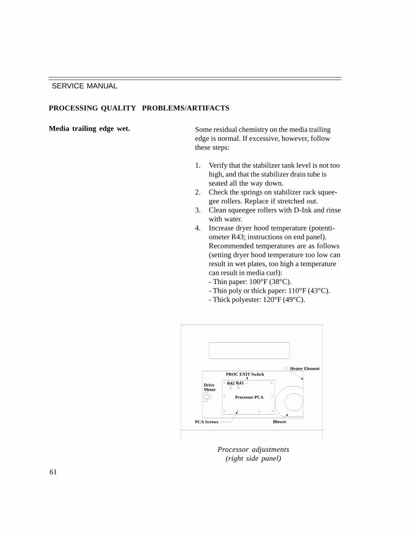
SERVICE MANUAL
61
R42 R43
Processor PCA
PCA Screws
DriveMotor
Blower
Heater ElementPROC EXIT Switch
Processor adjustments(right side panel)
Some residual chemistry on the media trailingedge is normal. If excessive, however, followthese steps:
1. Verify that the stabilizer tank level is not toohigh, and that the stabilizer drain tube isseated all the way down.
2. Check the springs on stabilizer rack squee-gee rollers. Replace if stretched out.
3. Clean squeegee rollers with D-Ink and rinsewith water.
4. Increase dryer hood temperature (potenti-ometer R43; instructions on end panel).Recommended temperatures are as follows(setting dryer hood temperature too low canresult in wet plates, too high a temperaturecan result in media curl):- Thin paper: 100°F (38°C).- Thin poly or thick paper: 110°F (43°C).- Thick polyester: 120°F (49°C).
Media trailing edge wet.
PROCESSING QUALITY PROBLEMS/ARTIFACTS

SERVICE MANUAL
62
1. Check the activator and dryer temperatures.
2. Clean the rollers.3. Change processor chemistry.4. Increase the replenishment rate.
1. Decrease dryer temperature.
1. Clean the rollers.2. Change processor chemistry.
Brownish-looking platesin silver areas.
Yellow stabilizer stains.
Dirty roller marks on plates.
PROCESSING QUALITY PROBLEMS/ARTIFACTS(...cont.)

SERVICE MANUAL
63
PROCESSOR MECHANICAL PROBLEMS
1. Pull the rack out of the platesetter and check thatthe idler gears are meshing properly with the othergears. Adjust gears if necessary.
2. Check the end play of rollers, which should beapproximately 0.010 to 0.020" (0.25 to 0.5 mm).
3. Check for loose pulley or gear set screws. Adjustworm gear drive to better mesh with other gears.
1. Check that the activator and stabilizer transportracks turn freely by hand.
2. Lower the drive motor to increase belt tension.3. If motor cannot be moved lower, shim the motor
bracket away from the frame using the lock wash-ers.
1. Squealing noise may be the pulley on the end of theworm gear. Apply light oil or Teflon spray.
2. Motors generally make noise. If too loud, replaceprocessor drive motor.
1. Check to see if the hoses coming from pumps arepinched.
2. Replace pumps.
Activator or Stabilizer rollers don’t turn.
Processor drive motor jumping.
Processor noisy.
Replenishmentpumps noisy.

SERVICE MANUAL
64
Spurious lowreplenishmentlevel error message.
Effluent probe not working.
Processor exit switchdoes not work.
This problem is caused by faulty replenishmentlevel probes.1. Check the probe connectors.2. Check the cable. Place one ohmmeter
probe on replenishment probe and the otheron the P2 cable. Check both replenishmentprobes for continuity. If cable checks outOK, replace the PCA. Otherwise, replacethe cable.
1. Check probe connector.2. Check cable P3 and PCA (see procedures
under Spurious low replenishmentmessage)
1. Remove the right-side end panel. Push theexit switch actuator at a 45° angle. Anindicator light should turn on after a 6-second time delay from the switch clickingon.
- If there is not an audible click whenthe switch is actuated, readjust theswitch. If it cannot be readjusted,replace the switch.
- If the switch actuates but the lightdoesn’t come on, replace the switchand cable.
- If a new switch and cable does notresolve the problem, replace thePCA.
PROCESSOR SENSOR PROBLEMS

SERVICE MANUAL
65
Dryer not heating. 1. Check and re-seat connectors J4 and J12 on theProcessor PCA.
2. Check fuses F3 and F4 on the processor PCA.3. Check the Processor PCA
3.1. Check that dryer heater LEDs A and B are onwhen the heater should be on (i.e., processor on andHeater Up To Temperature light not on). If LEDsdo not go on, replace the processor PCA.
3.2. If Heater Up To Temperature light is on, settemperature by adjusting potentiometer R43.Clockwise turns heat up on most PCAs (instructionsare on the inside of the processor panel).
3.3. If Heater Up To Temperature light is always onregardless of the R43 setting, replace the thermistor.
4. Check heater element.4.1. Remove dryer heater assembly from processor.4.2. Check heater element resistance with anohmmeter. Normal values are:
Pin 1 to Pin 2: 45ΩPin 1 to Pin 3: 45ΩPin 2 to Pin 3: 88ΩPin 1 to Pin 4: Open
PROCESSOR ELECTRICAL PROBLEMS
SERVICE MANUAL
66
1. Check the effluent tank. If it is full, thepumps will not come on.
2. If the replenishment tanks are low the pumpwill not come on.
3. Check the “Check Pump prime” light onprocessor PCA. If the light does not comeon when the pumps should be on, replacethe processor PCA.
4. Measure the voltage across the pumps atTS2-2 (brown) and TS2-3 (blue).- If 220V is present, replace pump
assembly.- If 220V isn’t present, the replace
the processor PCA.
1. Verify that there is chemistry in the replen-ishment tanks.
2. Check for leaking hoses.3. Check for air in the hoses. If there is,
unplug the hose from tank and hold the endover the tank as it pumps until the air iscleared.
4. Check for pinched hoses.5. Adjust pump rate (see Installation Guide
chapter 1 for adjustment procedures).
1. Turn heat down on processor PCA byadjusting potentiometer R42 (the tempera-ture specification is 86º±2ºF or 30º±1ºC).
2. Replace temperature probe.
Replenishment pumps notturning.
Pumps turning butfluid output isinadequate.
Activator bath is too hot.
PROCESSOR ELECTRICAL PROBLEMS (...cont.)

SERVICE MANUAL
67
Processor drive motordoes not work.
1. Remove both racks and turn on the proces-sor. If the motor comes on with the racksremoved, replace one rack at a time. Ifadding a rack causes the motor to stop,check the meshing of the gears and theroller end play of that rack.
2. Check the worm drive.3. Remove the right-side end panel, and
measure the voltage across motor.- If voltage reads 220V, with motor
on, but the motor is not spinning,replace motor.
- If there is no voltage across themotor, check fuse F5 on the PCA.If the fuse is good, replace thePCA.
4. Turn the white motor fan blade by hand. If itdoesn’t turn easily, disconnect the drive beltand try again. If it still does not turn easily,replace the motor assembly.
PROCESSOR ELECTRICAL PROBLEMS (...cont.)

SERVICE MANUAL
68
1. Check for excessive curl in media. Lay a12" length of material on a flat surface andhold down one end. If the other end of themedia curls up more than 2", replace media,it does not meet the manufacturer's specifi-cations.
2. Decrease dryer hood temperature (potenti-ometer R43; instructions on end panel).
MEDIA PROBLEMS
Media has excessive curl.

SERVICE MANUAL
69
PRESS-RELATED PROBLEMS(refer to troubleshooting guidesfor supplies for mostpress problems)
Short run length 1. Check press roller settings. Recommended settingsfor most presses are:- Form to Plate stripe: 1/8" (3 mm)- Plate to Blanket stripe: 3/16" (5 mm)
2. Verify that exposure is set correctly by checkingD
max. Laser power too high can cause short run
lengths.3. Reduce laser power.

1 2 3 4 5 6 7 8
A
B
C
D
87654321
D
C
B
A
120
221
322
423
524
625
726
827
92810291130123113321433153416351736183719
TO RIP
BROWN NCRED PRN GNDORANGEYELLOWGREEN
NCPRN GNDNC
BLUEVIOLET
PRN GNDNC
GRAYWHITE
PRN GNDNC
BLACKBROWNRED
PRN GNDPIX ENBLPIX ENBL *
ORANGEYELLOWGREEN
PIX CLKPIX CLK *PRN D0
BLUEVIOLETGRAY
PRN D0 *PRN D1PRN D1 *
WHITEBLACKBROWNREDORANGEYELLOWGREENBLUEVIOLETGRAYWHITEBLACKBROWNREDORANGEYELLOWGREENBLUEVIOLETNCNCNC
PRN D2PRN D2 *PRN D3PRN D3 *PRN D4PRN D4 *PRN D5PRN D5 *PRN D6PRN D6 *PRN D7PRN D7 *PRN R / W *PRN R * / W PRN STRBPRN STRB *PRN ACKPRN ACK *PRN GND
12345678910111213141516171819202122232425262728293031323334353637383940
123456
J3
1 2 3 4 5 6 7 8 9 10 11 12 13 14 15 16 17 18 19 20 21 22 23 24 25 26 27 28 29 30 31 32 33 34 35 36 37 38 39 40 41 42 43 44 45 46 47 48 49 50
J9
J8
123456789
10
123
123456
123456
123456
J6
J7
J1
J14
J11
SENSOR ASSY
GALVO ASSY
LASER ASSY
INTERLOCK ASSY
POWER SUPPLYDRAWER
J4
BLACK
BLACK
BLACK
BLACK
BLACK
RED
RED
YELLOW
BLUE
ORANGE
+5V
+5V
+12V
-12V
+24V
GND
GND
GND
GND
GND
-12VINTERLOCK PWR
NC
RED
RED
RED
RED
GREEN
GREEN
GREEN
BLUE
GRAYWHITE
WHITE
WHITE
BLACK
BLACK
BLACK
BLACK
BROWN
LASERGND-12VGNDPHOTODIODEGND
G DRV0 +G SENSE +G DRV1 +G DRV0 -G SENSE -G DRV1 -
SOS CSOS SIGSOS REFSOT CSOT SIGSOT REF
RED
CONTROLLER PCA
RE
D
RE
D
RE
D
RE
D
BR
OW
N
WH
ITE
BL
AC
K
GR
AY
GR
AY
GR
AY
GR
AY
GR
AY
WH
ITE
WH
ITE
WH
ITE
WH
ITE
BL
AC
K
BL
AC
K
BL
AC
K
BL
AC
K
VIO
LE
T
VIO
LE
T
VIO
LE
T
VIO
LE
T
VIO
LE
TB
LU
E
BL
UE
BL
UE
BL
UE
BL
UE
GR
EE
N
GR
EE
N
GR
EE
N
GR
EE
N
GR
EE
NY
EL
LO
W
YE
LL
OW
YE
LL
OW
YE
LL
OW
YE
LL
OW
OR
AN
GE
OR
AN
GE
OR
AN
GE
OR
AN
GE
BR
OW
N
BR
OW
N
BR
OW
N
BR
OW
NR
ED
OR
AN
GE
803319-002CABLE
807150-002CABLE
807046-001
806307-002
803280-001 IR
807049-001
807151-001
BROWN
522980-001 IR522980-002 RED
DC POWERWIRE COLOR
REDYELLOW
BLUEORANGEWHITEBLACKGREEN
VOLTAGE
+5V+12V-12V+24V
SIGNALGROUND
CHASISE GND
AC POWERWIRE COLOR
VOLTAGE
BROWNBLUE
GREEN/YELLOW
AC+AC-
GROUNDWHITEBLACK
GREEN
DOMESTIC INTERNATIONAL
1
2
3
4
5
6
7
8
1
2
3
4
5
6
7
8
9
10
11
12
13
14
15
16
J1
J2
J3J4
J5
J61
2
3
4
5
6
7
8
9
10
1
2
3
4
5
6
7
8
9
10
11
12
1
2
3
4
5
6
7
8
9
10
11
12
13
14
1
2
3
4
5
6
7
8
9
10
PIN ASSIGNMENTSFROM FRONT OF P. S. DRAWER
SWITCH
CIRCUIT BREAKER
AC IN240 VAC50 / 60 HZ
VENT FAN 900894-001
GREEN
600267-002AC +
AC -
AC +
AC -
EMI FILTER
900813-001
1
2
3
LINE
NEUTRAL
GROUND
+5V+5VGNDGNDGND+24V-12V+12V
+ GND
POWERDISTRIBUTIONPCA
522780
(1)(2, 3)
(5, 6, 7,)(4)(8)
ENG STP +5V
ENG STEPPER
ENG STP +24VENG STP GND+24VGND
J1
(1, 7)(3)(4)(6)
(12)(11)
(2, 5, 8, 9, 10)
CONT +5VCONT +12VCONT -12VCONT +24VCONT GNDVENT FAN +24VENT FAN RTN
INTERFACEOP PANEL
(1, 2)(11)(6)(7)
(3, 5, 10, 14)(8)(4)(13)
(9, 12)
J4
J5INTRF +5VINTRF +12VINTRF -12VINTRF +24VINTRF GNDOP +5VOP +12VOP -12VOP GND
PROCESSORAC CABLE
DC POWER SUPPLY901142-001
807203-001
1 2
3 4
BR
OW
N
BL
UE
BLUE
BROWN
BROWN
BLUE
GREEN
+5V FUSE
+24V FUSE
-12V FUSE
+12V FUSE
WHITE
BLACK
CORCOM30VK6
25A / 40 F250V
POWER SUPPLY INTEGRATED ASSY808046-TAB
CONTROLLER
YELLOW
YELLOW
RED
RED
BLUE
BLUE
ORANGE
BLACK
BLACK
RED
YELLOW
BLUE
ORANGE
ORANGE
BLACK
BLACK
BLACK
BLACK
ORANGE
ORANGE
RED
803319-002CABLE
803321-001CABLE
803312-003CABLE
INTERFACE PCA
J12
J16
J1 [NU]
J6 [NU]
J4 [NU]
J2
J3
J5
J14
[ NU ] J13
J15
J111 2 3 4 5 6 7 8 9 10 11 12 13 14 15 16 17 18 19 20
12345678910111213141516171819202122232425262728
293031323334353637383940
BROWNREDORANGEYELLOWGREENBLUEVIOLETGRAYWHITEBLACKBROWNREDORANGEYELLOWGREENBLUEVIOLETGRAYWHITEBLACKBROWNREDORANGEYELLOWGREENBLUEVIOLETGRAYWHITEBLACKBROWNREDORANGEYELLOWGREENBLUEVIOLET
BROWNREDORANGEYELLOWGREENBLUEVIOLETGRAYWHITEBLACKBROWNREDORANGEYELLOWGREENBLUEVIOLETGRAYWHITEBLACKBROWNREDORANGEYELLOWGREENBLUEVIOLETGRAYWHITEBLACKBROWNREDORANGEYELLOWGREENBLUEVIOLET
GRAYWHITEBLACK
NUNUNUNU
NUNUNUNUNUNUNUNU
NUNUNU
NU
GRAYWHITEBLACKBROWNREDORANGEYELLOWGREENBLUEVIOLETGRAYWHITEBLACK
1234567891011121314151617181920212223242526272829303132333435363738394041424344454647484950
GNDFD STEPFD STEP *GNDFD RESETFD RESET *GNDTR STEPTR STEP *GNDTR RESETTR RESET *GNDEX STEPEX STEP *GNDEX RESETEX RESET *GNDCUT STEPCUT STEP *GNDCUT RESETCUT RESET *GNDPLG * / OPPLG / OP *GNDSTEP SYNCSTEP SYNC *GNDSPARE 3 *SPARE 3GNDFD / TR DIRFD / TR DIR *GNDSPARE 1 *SPARE 1 GNDSPARE 0 *SPARE 0 GNDEX DIREX DIR *GNDSPARE 2 *SPARE 2 GNDGND
NO MEDIA +5VNO MEDIA SIGNO MEDIA GND
GUIDE B +5VGUIDE B SIGGUIDE B GND
1 2 3 4 5 6 7 8 9 10 11 12 13 14 15 16 17 18 19 20 21 22 23 24 25 26 27 28 29 30 31 32 33 34 35 36 37 38 39 40 41 42 43 44 45 46 47 48 49 50
1234567891011121314151617181920212223242526NC
WORKING TANKS LOW *GNDREPLN TANKS LOW *GNDEFF TANK HIGH *GNDPROC TEMP *GNDFILM EXIT *GNDSPARE *GND+5V PULL-UPSOJ *+5V PULL-UPDRIVE INH *+5V PULL-UPRESET *+5V PULL-UPPUMP PRIME *+5V PULL-UPSPARE *NUNUNU
SHUTTERSOLENOID
SOLENOIDSHUTTER
806099-001
806099-001
1234
+24VSHUTTER DRV *+24vSHUTTER DRV *
ORANGE
ORANGEWHITE
WHITE
WHITEWHITE
WHITEWHITE
1234
12
ORANGEWHITE
+24VFAN DRV *
1
2
COOLING FAN
REDBLACK
12345678910
BLACK
BLACK
BLACK
BLACK
RED
RED
YELLOW
BLUE
ORANGE
POWERSUPPLYDRAWER
J5
123456
123456
1234
NO MEDIASENSOR (NO)
807091-001
SENSOR (NO)
807091-001
1
23
56
7
10
11
14
BROWNREDORANGEYELLOWGREENBLUEVIOLETGRAYWHITEBLACKBROWNREDORANGEYELLOWGREENBLUEVIOLETGRAYWHITEBLACKBROWNREDORANGEYELLOWGREENBLUE
807520-002CABLE
806306-002CABLE
807226-001CABLE
807204-001CABLE
804140-002CABLEORANGE
ORANGEWHITE
WHITEPUNCH
807301-001
803318-002CABLE
REDORANGEYELLOWGREENBLUEVIOLETGRAYWHITEBLACKBROWNREDORANGEYELLOWGREENBLUEVIOLETGRAYWHITEBLACKBROWNREDORANGEYELLOWGREENBLUE
523060-001
J1
1234567891011121314151617181920212223242526
PROCESSOR
1234
1234
1234
1234
1234
1234
1234
1234
J5J4 J8
J9 [NU]
J10
J11 [NU]
J12
J7
J6
J2
J3
TS1TS2
1 2 3 41 2 3 41 2 3 4
NU
NU
NU
GR
EE
NB
LA
CK
BL
AC
KB
LA
CK
BL
AC
KB
LA
CK
BL
AC
K
BL
AC
KB
LA
CK
ACT TEMP PROBE 806786-001
BLACKRED
NUNU
DRIER TEMP SENSOR 600330-001
806788-001
NU
WHITE
WHITEBLACK
ENGINE STEPPER PCA
123
4
5
6
BLACKBLACKREDBLACKORANGE
POWERSUPPLYDRAWER
J1
523190-004
J1 [ NU ]
J4
J6 [ NU ]
J2
803321-001CABLE
BROWNREDORANGEYELLOWGREENBLUEVIOLETGRAYWHITEBLACKBROWNREDORANGEYELLOWGREENBLUEVIOLETGRAYWHITEBLACKBROWNREDORANGEYELLOWGREENBLUEVIOLETGRAYWHITEBLACKBROWNREDORANGEYELLOWGREENBLUEVIOLETGRAYWHITEBLACKBROWNREDORANGEYELLOWGREENBLUEVIOLETGRAYWHITEBLACK
123456789101112131415161718192021222324
2526272829303132333435363738394041424344454647484950
ORANGE+24V+24VGND
GNDGND
+5V
235167
J7
J3
J5
J8
123456789101112
1234
1
234
BLACK
BLACKWHITE
RED
1
234
1234
CUTTER SWITCH
CUTTER MOTOR
BLACK
BLACKWHITE
RED
1234
RED
BLACK
WH
CAPSTAN STEPPER804628-001
1234
RED
BLACKYELLOW
WHITE
1234
1234
BLUE
GREEN
YEL
803323-002
CUTTER ASSY
806127-001
POWER SUPPLY 220V
BROWN
GREEN
BLUE
L1
GND
L2
EXIT SWITCH 600333-001
806789-001WHITE
WHITEBLACK
NU
WORKING TANK SENSORS 806800-001
806793-001
WHITEBLACK
NUNU
NUNU
REPLENISHMENT TANK SENSORS 806709-001
806790-001
BLACKBLACK
WHITEWHITEACT
ACT
STAB
STAB
EFFLUENT TANK LEVEL PS 806815-002
806792-001
WHITEBLACK
SCHEMATIC PAGE 2
SCHEMATIC PAGE 3
SCHEMATIC PAGE 4
SCHEMATIC PAGE 5
SCHEMATIC PAGE 6
CABLE 807530-001
GUIDE B
123 NU
807220-TAB RED
600322-001250V 7A
ALL FUSES
806420-TAB
SCHEMATIC PAGE 11 6
700636-001 A
Title
Size:CODE
MATERIAL
Sheet of
B
WIRING DIAGRAM - PlateStream SC
This document and the information it contains is the property of Printware Inc., and may not bereproduced, copied, disclosed to others, or disposed of directly or indrectly without authoriza-tion from Printware Inc. Both the document and its contents are to be treated as confidential &proprietary, and may not be used in any manner not consistent with the rights of Printware Inc.
SCALE: NONE
REVCOMM. VERSIONINSP.FIRST USED ON
DO
NO
T S
CA
LE
DR
AW
ING
TOLERANCE UNLESS OTHERWISE SPECIFIEDANGLES..............................1 PLACE DECIMALS..........2 PLACE DECIMALS..........3 PLACE DECIMALS.......... .010
.5 DEG---.02
FINISH
PRINTWARE INC.ST. PAUL, MN
BYDRAWN
ENG.ENG.
APPVL.
MFG
Q.A.
DAS 06/21/00
REV ECO DESCRIPTION DRAWN BY / DATE/ DATE APPVL06860 INITAL RELEASE DAS 11/22/00A
523200-001
WHEEL CUTTER
SHEAR CUTTER
DECURL / EXIT
PAPER FEED
MARKER TRANS.
Printware807514-001
1 12 2
4
9
TO RIP
807521-004
NUNUNUNUNUNU
NUNUNUNUNUNUNUNUNU
4321
NUNUNU
J2, J5, J15, J16, AND SPARE
J2
J3
J6
CONNECTORS NOT USED

1 2 3 4 5 6
A
B
C
D
654321
D
C
B
A
2 6
A
Title
Size:CODE
MATERIAL
Sheet of
B
WIRING DIAGRAM - PlateStream N.O.
This document and the information it contains is the property of Printware Inc., and may not bereproduced, copied, disclosed to others, or disposed of directly or indrectly without authoriza-tion from Printware Inc. Both the document and its contents are to be treated as confidential &proprietary, and may not be used in any manner not consistent with the rights of Printware Inc.
SCALE: NONE
REVCOMM. VERSIONINSP.
FIRST USED ONDO
NO
T S
CA
LE
DR
AW
ING
TOLERANCE UNLESS OTHERWISE SPECIFIED
ANGLES..............................
1 PLACE DECIMALS..........
2 PLACE DECIMALS..........3 PLACE DECIMALS.......... .010
.5 DEG---.02
FINISH
PRINTWARE INC.ST. PAUL, MN
BYDRAWN
ENG.
ENG.APPVL.
MFG
Q.A.
DAS 11/22/00
DC POWERWIRE COLOR
REDYELLOW
BLUEORANGEWHITEBLACKGREEN
VOLTAGE
+5V+12V-12V+24V
SIGNALGROUND
CHASISE GND
AC POWERWIRE COLOR
VOLTAGE
BROWNBLUE
GREEN/YELLOW
AC+AC-
GROUNDWHITEBLACK
GREEN
DOMESTIC INTERNATIONAL
1
2
3
4
5
6
7
8
1
2
3
4
5
6
7
8
9
10
11
12
13
14
15
16
J1
J2
J3J4
J5
J61
2
3
4
5
6
7
8
9
10
1
2
3
4
5
6
7
8
9
10
11
12
1
2
3
4
5
6
7
8
9
10
11
12
13
14
1
2
3
4
5
6
7
8
9
10
PIN ASSIGNMENTSFROM SIDE OF P. S. DRAWER
SWITCH
CIRCUIT BREAKER
AC IN240 VAC50 / 60 HZ
VENT FAN 900894-001
GREEN
600267-002AC +
AC -AC +
AC -
EMI FILTER
900813-001
1
2
3
LINE
NEUTRAL
GROUND
+5V+5VGNDGNDGND+24V-12V+12V
+ GND
J6
POWERDISTRIBUTIONPCA
522780
(1)(2, 3)
(5, 6, 7,)(4)(8)
ENG STP +5VENG STEPPER
ENG STP +24VENG STP GND+24VGND
J1
(1, 7)(3)(4)(6)
(12)(11)
(2, 5, 8, 9, 10)
CONT +5VCONT +12VCONT -12VCONT +24VCONT GNDVENT FAN +24VENT FAN RTN
INTERFACEOP PANEL
(1, 2)(11)(6)(7)
(3, 5, 10, 14)(8)(4)(13)
(9, 12)
J4
J5INTRF +5VINTRF +12VINTRF -12VINTRF +24VINTRF GNDOP +5VOP +12VOP -12VOP GND
PROCESSORAC CABLE
DC POWER SUPPLY901142-001
807203-001
1 2
3 4B
RO
WN
BL
UE
BLUE
BROWN
BROWN
BLUE
GREEN
+5V FUSE
+24V FUSE
-12V FUSE
+12V FUSE
WHITE
BLACK
CORCOM30VK6
25A / 40 F250V
POWER SUPPLY INTEGRATED ASSY
808046-TAB
YELLOW
YELLOW
RED
RED
BLUE
BLUE
ORANGE
BLACK
BLACK
RED
YELLOW
BLUE
ORANGE
ORANGE
BLACK
BLACK
BLACK
BLACK
ORANGE
ORANGE
RED
803319-002CABLE
803321-001CABLE
807520-002CABLE
CONTROLLER
600322-001250V 7A
ALL FUSES
700636-001
806420-TAB
SCHEMATIC PAGE 2
TAB BLOCK
PART NO. DESCRIPTION
807046-001 NORTH AMERICAN
807046-501 INTERNATIONAL
806420-003806420-004
FOR NORTH AMERICAN USE (BLACK, WHITE, GREEN WIRE)FOR INTERNATIONAL USE (BROWN, BLUE, GREEN/YELLOW WIRE)
J2 NU
J3 NU

1 2 3 4 5 6
A
B
C
D
654321
D
C
B
A
3 6
700636-001 A
Title
Size:
MATERIAL
Sheet of
B
WIRING DIAGRAM - PlateStream SC
This document and the information it contains is the property of Printware Inc., and may not bereproduced, copied, disclosed to others, or disposed of directly or indrectly without authoriza-tion from Printware Inc. Both the document and its contents are to be treated as confidential &proprietary, and may not be used in any manner not consistent with the rights of Printware Inc.
SCALE: NONE
REVCOMM. CODE VERSIONINSP.
FIRST USED ONDO
NO
T S
CA
LE
DR
AW
ING
TOLERANCE UNLESS OTHERWISE SPECIFIED
ANGLES..............................
1 PLACE DECIMALS..........
2 PLACE DECIMALS..........3 PLACE DECIMALS.......... .010
.5 DEG---.02
FINISH
PRINTWARE INC.ST. PAUL, MN
BYDRAWN
ENG.
ENG.APPVL.
MFG
Q.A.
DAS 11/22/00
120
221
322
423
524
625
726
827
92810291130123113321433153416351736183719
TO RIP
BROWN NCRED PRN GNDORANGEYELLOWGREEN
NCPRN GNDNC
BLUEVIOLET
PRN GNDNC
GRAYWHITE
PRN GNDNC
BLACKBROWNRED
PRN GNDPIX ENBLPIX ENBL *
ORANGEYELLOWGREEN
PIX CLKPIX CLK *PRN D0
BLUEVIOLETGRAY
PRN D0 *PRN D1PRN D1 *
WHITEBLACKBROWNREDORANGEYELLOWGREENBLUEVIOLETGRAYWHITEBLACKBROWNREDORANGEYELLOWGREENBLUEVIOLETNCNCNC
PRN D2PRN D2 *PRN D3PRN D3 *PRN D4PRN D4 *PRN D5PRN D5 *PRN D6PRN D6 *PRN D7PRN D7 *PRN R / W *PRN R * / W PRN STRBPRN STRB *PRN ACKPRN ACK *PRN GND
12345678910111213141516171819202122232425262728293031323334353637383940
123456
J3 [ NU ]
1 2 3 4 5 6 7 8 9 10 11 12 13 14 15 16 17 18 19 20 21 22 23 24 25 26 27 28 29 30 31 32 33 34 35 36 37 38 39 40 41 42 43 44 45 46 47 48 49 50
J9
J8
12345678910
123
123456
123456
123456
J6
J7
J1
J14
J11
SENSOR ASSY
GALVO ASSY
LASER ASSY
INTERLOCK ASSY
POWER SUPPLYDRAWER
J4
BLACK
BLACK
BLACK
BLACK
BLACK
RED
RED
YELLOW
BLUE
ORANGE
+5V
+5V
+12V
-12V
+24V
GND
GND
GND
GND
GND
-12VINTERLOCK PWR
NC
RED
RED
RED
RED
GREEN
GREEN
GREEN
BLUE
GRAYWHITE
WHITE
WHITE
BLACK
BLACK
BLACK
BLACK
BROWN
LASERGND-12VGNDPHOTODIODEGND
G DRV0 +G SENSE +G DRV1 +G DRV0 -G SENSE -G DRV1 -
SOS CSOS SIGSOS REFSOT CSOT SIGSOT REF
RED
KIT 807117-004
CONTROLLER PCA
522980-001 IR522980-002 RED
FIRMWARE: U76 = CONTROL HARDWAREU43 = PIXEL RATEU196 = ENGINE PROCESSORU199 = SCAN PROCESSOR
TO INTERFACE PCA J12
RE
D
RE
D
RE
D
RE
D
BR
OW
N
WH
ITE
BL
AC
K
GR
AY
GR
AY
GR
AY
GR
AY
GR
AY
WH
ITE
WH
ITE
WH
ITE
WH
ITE
BL
AC
K
BL
AC
K
BL
AC
K
BL
AC
K
VIO
LE
T
VIO
LE
T
VIO
LE
T
VIO
LE
T
VIO
LE
TB
LU
E
BL
UE
BL
UE
BL
UE
BL
UE
GR
EE
N
GR
EE
N
GR
EE
N
GR
EE
N
GR
EE
NY
EL
LO
W
YE
LL
OW
YE
LL
OW
YE
LL
OW
YE
LL
OW
OR
AN
GE
OR
AN
GE
OR
AN
GE
OR
AN
GE
BR
OW
N
BR
OW
N
BR
OW
N
1 2 3 4 5 6 7 8 9 10 11 12 13 14 15 16 17 18 19 20 21 22 23 24 25 26 27 28 29 30 31 32 33 34 35 36 37 38 39 40 41 42 43 44 45 46 47 48 49 50
BR
OW
NR
ED
OR
AN
GE
803319-002CABLE
CABLE
807046-001
806307-002
803280-001 IR
807049-001
807151-001
CABLE 807530-001
807220-TAB RED
SCHEMATIC PAGE 3
TO RIP
807521-004
CONNECTORS NOT USEDJ2, J5, J15, J16, AND SPARE
807150-002

1 2 3 4 5 6
A
B
C
D
654321
D
C
B
A
4 6
700636-001 A
Title
Size:
MATERIAL
Sheet of
B
WIRING DIAGRAM - PlateStream N.O.
This document and the information it contains is the property of Printware Inc., and may not bereproduced, copied, disclosed to others, or disposed of directly or indrectly without authoriza-tion from Printware Inc. Both the document and its contents are to be treated as confidential &proprietary, and may not be used in any manner not consistent with the rights of Printware Inc.
SCALE: NONE
REVCOMM. CODE VERSIONINSP.
FIRST USED ONDO
NO
T S
CA
LE
DR
AW
ING
TOLERANCE UNLESS OTHERWISE SPECIFIED
ANGLES..............................
1 PLACE DECIMALS..........
2 PLACE DECIMALS..........3 PLACE DECIMALS.......... .010
.5 DEG---.02
FINISH
PRINTWARE INC.ST. PAUL, MN
BYDRAWN
ENG.
ENG.APPVL.
MFG
Q.A.
DAS 11/22/00
INTERFACE PCA
523060-001
J12
J16
J1 [NU]
J6 [NU]
J4 [NU]
J2
J3
J5
J14
[ NU ] J13
J15
J11
1 2 3 4 5 6 7 8 9 10 11 12 13 14 15 16 17 18 19 20
12345678910111213141516171819202122232425262728
293031323334353637383940
BROWNREDORANGEYELLOWGREENBLUEVIOLETGRAYWHITEBLACKBROWNREDORANGEYELLOWGREENBLUEVIOLETGRAYWHITEBLACKBROWNREDORANGEYELLOWGREENBLUEVIOLETGRAYWHITEBLACKBROWNREDORANGEYELLOWGREENBLUEVIOLET
BROWNREDORANGEYELLOWGREENBLUEVIOLETGRAYWHITEBLACKBROWNREDORANGEYELLOWGREENBLUEVIOLETGRAYWHITEBLACKBROWNREDORANGEYELLOWGREENBLUEVIOLETGRAYWHITEBLACKBROWNREDORANGEYELLOWGREENBLUEVIOLET
GRAYWHITEBLACK
NUNUNUNU
NUNUNUNUNUNUNUNU
NUNUNU
NU
GRAYWHITEBLACKBROWNREDORANGEYELLOWGREENBLUEVIOLETGRAYWHITEBLACK
1234567891011121314151617181920212223242526272829303132333435363738394041424344454647484950
GNDFD STEPFD STEP *GNDFD RESETFD RESET *GNDTR STEPTR STEP *GNDTR RESETTR RESET *GNDEX STEPEX STEP *GNDEX RESETEX RESET *GNDCUT STEPCUT STEP *GNDCUT RESETCUT RESET *GNDPLG * / OPPLG / OP *GNDSTEP SYNCSTEP SYNC *GNDSPARE 3 *SPARE 3GNDFD / TR DIRFD / TR DIR *GNDSPARE 1 *SPARE 1 GNDSPARE 0 *SPARE 0 GNDEX DIREX DIR *GNDSPARE 2 *SPARE 2 GNDGND
NO MEDIA +5VNO MEDIA SIGNO MEDIA GND
GUIDE B +5VGUIDE B SIGGUIDE B GND
1 2 3 4 5 6 7 8 9 10 11 12 13 14 15 16 17 18 19 20 21 22 23 24 25 26 27 28 29 30 31 32 33 34 35 36 37 38 39 40 41 42 43 44 45 46 47 48 49 50
1234567891011121314151617181920212223242526
TO PROCESSOR
NC
WORKING TANKS LOW *GNDREPLN TANKS LOW *GNDEFF TANK HIGH *GNDPROC TEMP *GNDFILM EXIT *GNDSPARE *GND+5V PULL-UPSOJ *+5V PULL-UPDRIVE INH *+5V PULL-UPRESET *+5V PULL-UPPUMP PRIME *+5V PULL-UPSPARE *NUNUNU
ENGINE STEPPER
SHUTTERSOLENOID
SOLENOIDSHUTTER
806099-001
806099-001
1234
+24VSHUTTER DRV *+24vSHUTTER DRV *
ORANGE
ORANGEWHITE
WHITE
WHITEWHITE
WHITEWHITE
1234
12
ORANGEWHITE
+24VFAN DRV *
1
2
COOLING FAN
REDBLACK
12345678910
BLACK
BLACK
BLACK
BLACK
RED
RED
YELLOW
BLUE
ORANGE
POWERSUPPLYDRAWER
J5
123456
123456
1234
NO MEDIASENSOR (NO)
807091-001
SENSOR (NO)
807091-001
BR
OW
N
TO CONTROLLER PCA J9
RE
D
RE
D
RE
D
RE
D
BR
OW
N
WH
ITE
BL
AC
K
GR
AY
GR
AY
GR
AY
GR
AY
GR
AY
WH
ITE
WH
ITE
WH
ITE
WH
ITE
BL
AC
K
BL
AC
K
BL
AC
K
BL
AC
K
VIO
LE
T
VIO
LE
T
VIO
LE
T
VIO
LE
T
VIO
LE
TB
LU
E
BL
UE
BL
UE
BL
UE
BL
UE
GR
EE
N
GR
EE
N
GR
EE
N
GR
EE
N
GR
EE
NY
EL
LO
W
YE
LL
OW
YE
LL
OW
YE
LL
OW
YE
LL
OW
OR
AN
GE
OR
AN
GE
OR
AN
GE
OR
AN
GE
BR
OW
N
BR
OW
N
BR
OW
N
RE
DO
RA
NG
E
1 2 3 4 5 6 7 8 9 10 11 12 13 14 15 16 17 18 19 20 21 22 23 24 25 26 27 28 29 30 31 32 33 34 35 36 37 38 39 40 41 42 43 44 45 46 47 48 49 50
123456789101112131415161718192021222324
2526272829303132333435363738394041424344454647484950
1
23
56
7
10
11
14
BROWNREDORANGEYELLOWGREENBLUEVIOLETGRAYWHITEBLACKBROWNREDORANGEYELLOWGREENBLUEVIOLETGRAYWHITEBLACKBROWNREDORANGEYELLOWGREENBLUE
807520-002CABLE
806306-002CABLE
807226-001CABLE
807204-001CABLE
804140-002CABLE
803318-002CABLE
ORANGE
ORANGEWHITE
WHITEPUNCH
807301-001
J1
CABLE 807530-001
J16
J15
J11
J12
J13
J14
J1J2
J3J4
J5J6
11
11
11
12
12
1212
4950
394025261920
INTERFACEBOARD LAY-OUT
SENSORS
TO
PCA J7
50 49
2 1
123 NU
GUIDE B
SCHEMATIC PAGE 4
NUNUNU
NUNUNUNUNUNU
NUNU
NUNUNUNUNUNUNU

1 2 3 4 5 6
A
B
C
D
654321
D
C
B
A
5 6
700636-001 A
Title
Size:
MATERIAL
Sheet of
B
WIRING DIAGRAM - PlateStream SC
This document and the information it contains is the property of Printware Inc., and may not bereproduced, copied, disclosed to others, or disposed of directly or indrectly without authoriza-tion from Printware Inc. Both the document and its contents are to be treated as confidential &proprietary, and may not be used in any manner not consistent with the rights of Printware Inc.
SCALE: NONE
REVCOMM. CODE VERSIONINSP.
FIRST USED ONDO
NO
T S
CA
LE
DR
AW
ING
TOLERANCE UNLESS OTHERWISE SPECIFIED
ANGLES..............................
1 PLACE DECIMALS..........
2 PLACE DECIMALS..........3 PLACE DECIMALS.......... .010
.5 DEG---.02
FINISH
PRINTWARE INC.ST. PAUL, MN
BYDRAWN
ENG.
ENG.APPVL.
MFG
Q.A.
DAS 11/22/00
INTERFACE PCA J11
ENGINE STEPPER PCA
123
4
5
6
BLACKBLACKREDBLACKORANGE
POWERSUPPLYDRAWER
J1
523190-004
J1 [ NU ]
J4
J6 [ NU ]
J2
803321-001CABLE
BROWNREDORANGEYELLOWGREENBLUEVIOLETGRAYWHITEBLACKBROWNREDORANGEYELLOWGREENBLUEVIOLETGRAYWHITEBLACKBROWNREDORANGEYELLOWGREENBLUEVIOLETGRAYWHITEBLACKBROWNREDORANGEYELLOWGREENBLUEVIOLETGRAYWHITEBLACKBROWNREDORANGEYELLOWGREENBLUEVIOLETGRAYWHITEBLACK
1234567891011121314151617181920212223242526272829303132333435363738394041424344454647484950
GNDFD STEPFD STEP *GNDFD RESETFD RESET *GNDTR STEPTR STEP *GNDTR RESETTR RESET *GNDEX STEPEX STEP *GNDEX RESETEX RESET *GNDCUT STEPCUT STEP *GNDCUT RESETCUT RESET *GNDPLG * / OPPLG / OP *GNDSTEP SYNCSTEP SYNC *GNDSPARE 3 *SPARE 3GNDFD / TR DIRFD / TR DIR *GNDSPARE 1 *SPARE 1 GNDSPARE 0 *SPARE 0 GNDEX DIREX DIR *GNDSPARE 2 *SPARE 2 GNDGND
123456789101112131415161718192021222324
2526272829303132333435363738394041424344454647484950
803318-002CABLE
ORANGE+24V+24VGND
GNDGND
+5V
235167
J7
J3
J5
J8
123456789101112
1234
BLACK
BLACKWHITE
RED
1
234
1234
CUTTER SWITCH
CUTTER MOTOR
BLACK
BLACKWHITE
RED
1234
RED
BLACK
WH
CAPSTAN STEPPER804628-001
1234
RED
BLACKYELLOW
WHITE
1234
BLUE
GREEN
YEL
803323-002
CUTTER ASSY
806127-001
1
J1 [NU]
WHEEL CUTTER
J8
SHEAR CUTTER
J2
DECURL / EXIT
J3
PAPER FEED
J4
MARKER TRANS.
J5
POWER
J6
J7
1
1
1
1
1
1
1
CUT
DCRL
PF
MT
STEPPER BOARDLAY-OUT
SCHEMATIC PAGE 5
WHEEL CUTTER
SHEAR CUTTER
DECURL / EXIT
PAPER FEED
MARKER TRANS.

1 2 3 4 5 6
A
B
C
D
654321
D
C
B
A
6 6
700636-001 A
Title
Size:
MATERIAL
Sheet of
B
WIRING DIAGRAM - PlateStream N.O.
This document and the information it contains is the property of Printware Inc., and may not bereproduced, copied, disclosed to others, or disposed of directly or indrectly without authoriza-tion from Printware Inc. Both the document and its contents are to be treated as confidential &proprietary, and may not be used in any manner not consistent with the rights of Printware Inc.
SCALE: NONE
REVCOMM. CODE VERSIONINSP.
FIRST USED ONDO
NO
T S
CA
LE
DR
AW
ING
TOLERANCE UNLESS OTHERWISE SPECIFIED
ANGLES..............................
1 PLACE DECIMALS..........
2 PLACE DECIMALS..........3 PLACE DECIMALS.......... .010
.5 DEG---.02
FINISH
PRINTWARE INC.ST. PAUL, MN
BYDRAWN
ENG.
ENG.APPVL.
MFG
Q.A.
DAS 11/22/00
HEATER FAN 806705-001
PROCESSOR DRIVE MOTOR
806703-001
7
6
5
1
4
3
2
8
7
6
5
4
3
2
1
J3J2J6 J1261
111J9 J10 J11 J12 J711111
DRYERTEMP
ACTTEMP
TP4 TP3
J8
1
F22A 250V
F35A 250V
F45A 250V
F52A 250V
F15A 250V
J5J4
1 1
TS1TS2
L2
GND
L1
POWER SUPPLY 220V
BROWN
GREEN
BLUE
BROWN
BLUE
GREEN
BLACK
BLACK
BL
AC
K
BL
AC
K
BL
AC
K
BL
AC
K
BL
AC
K
523150-001
GREEN
BLACK
BLACK
ACT TEMP PROBE 806786-001
DRIER TEMP SENSOR 600330-001
EXIT SWITCH 600333-001
EFFLUENT TANK LEVEL PS46 806815-001
PS 806815-002
EMI FILTER
TRANSFORMER
BL
AC
K
WH
ITE
PIN 1 IS BROWN PIN 26 IS GREEN
RE
D
BL
AC
K
BL
AC
K
WH
ITE
WH
ITE
WH
ITE
BL
AC
K
WH
ITE
CAL CAL
BLACKGREEN
GREEN
GREEN
BLACK
BLACK
WORKING TANK SENSORS 806800-001
REPLENISHMENT TANK SENSORS 806709-001
(PINS 1 & 2 ARE WHITE) (PINS 3 & 4 ARE BLACK) (PINS 2 & 4 ACT) (PINS 1 & 3 STAB)
GREEN
ACT BLANKET HEATER 600335-001
REPLENISHMENT PUMPS 806843-001
RED
RED
RIBBON CABLE TO INTERFACE BOARD PS46 806794-001
PS 807204-001
BLUE
BROWN
YELLOW/GREEN
DRYER HEATER 806712-001 GREEN
BLACK
BLACK
BLACK
BLACK
BLACK
BLACK
WIRING DIAGRAM PS46 808155-001 PSMP 807346-001
PS 807179-001
BL
AC
K
WH
ITE
CHASSIS GROUND
GREEN
MOUNTING SCREW
806790-001
806788-001
806789-001
806793-001
806792-001
SCHEMATIC PAGE 6
523200-001

Illustrated Parts List
700635-001 Rev A
LEADERS IN COMPUTER TO PLATE
PlateStream SCPlatesetter

Assembly Number: 808040-00X
PLATESTREAM SC
Revision: 01
FindNumber
QuantityUsed
ComponentNumber
ComponentDescription Parts List Page 1 of 1
001 1 808041-001 ASSY-IMAGER SC
002 1 807245-001 ASSY-MARKER 13" IR (SC)
002 1 807245-003 ASSY-MARKER 13" RED (SC)
003 1 808046-001 ASSY-POWER SUPPLY SC DOMESTIC (ORIGINAL)
003 1 808050-001 ASSY-POWER SUPPLY SC DOMESTIC


Assembly Number: 808041-001
ASSY-IMAGER SC
Revision: D
FindNumber
QuantityUsed
ComponentNumber
ComponentDescription Parts List Page 1 of 2
002 1 901273-003 KIT-FRAME SC
003 1 807601-001 PANEL-SKIN FRONT
004 1 807601-002 PANEL-SKIN FEED
005 1 807601-003 PANEL-SKIN EXIT
006 1 807601-004 PANEL-SKIN REAR
007 1 807602-001 COVER-TOP
008 1 807607-001 HINGE-CONTINUOUS
009 8 900823-002 LATCH-PULL FLUSH
012 6 900235-002 SCREW-SHOULDER CAP #8-32 X .5"
014 26 900047-000 WASHER-EXTERNAL LOCK #8
015 59 900445-006 SCREW-B.H. TORX #8-32 X .375"
020 28 901279-001 PLATE-NUT #8-32
044 1 808044-001 ASSY-TRANSPORT SC
049 1 807672-001 ASSY-LOWER GUIDE
052 2 900270-003 GAS CYLINDER 60 LBS.
054 6 900233-003 NUT-LOCK K #8-32
057 1 523190-004 PCA-STEPPER-SHEAR CUTTER
058 1 523060-001 PCA-INTERFACE
059 8 900341-003 BUSHING-SPACER, NYLON 6-32 X .375"
060 8 900336-000 NUT-SELF LOCKING HEX #6-32
061 8 900287-007 SCREW-PAN PHILLIPS PANHEAD #6-32 X .75"
062 4 900257 STUD- 10MM BALL- 5/16"-18 THREAD
063 2 900222-003 NUT-HEX 5/16"-18
064 4 900223-007 WASHER-LOCK HELICAL SPRING 5/16"
065 1 900270-009 GAS-CYLINDER 30 LBS.
066 1 900270-004 GAS CYLINDER 20 LBS.
067 1 806843-001 ASSY-PUMP
068 1 807629-001 BRACKET- PUMP MOUNTING
071 4 807624-001 ANGLE-CORNER
076 2 806709-002 ASSY-PROBE
077 1 806719-009 ASSY-TUBE ACTIVATOR
078 1 807312-002 ASSY-TUBE STABILIZER
079 1 806719-008 ASSY-TUBE ACTIVATOR
080 1 807312-003 ASSY-TUBE STABILIZER
081 1 806815-003 ASSY-PROBE EFFLUENT
084 1 807514-001 ASSY-INDICATOR LIGHT
087 2 806866-001 STOP-TRAY ADJUSTABLE
090 4 806825-001 PAD-RACK
116 1 901280-001 CONTAINER-SOLUTION
117 1 807625-001 LID-MODIFICATION
121 1 807637-001 PLATE-MOUNTING, POWER SUPPLY
123 1 807666-001 LABEL-PLATESTREAM SC LOGO

Assembly Number: 808041-001
ASSY-IMAGER SC
Revision: D86 1 804150-001 TRAY-EXIT


Assembly Number: 808044-001
ASSY-ROLLER TRANSPORT SMALL COMMERCIAL
Revision: C
FindNumber
QuantityUsed
ComponentNumber
ComponentDescription Parts List Page 1 of 3
001 1 807590-001 WELDMENT-13" ROLLER TRANSPORT
003 1 822307 WASHER-PRELOAD SPRING
005 2 900297-001 BEARING-BALL
006 2 803305-001 RETAINER-BEARING
010 2 807350-001 ROLLER-PINCH, TRACTION, 13"
011 1 804604-001 ROLLER-ALUMINUM CAPSTAN
012 4 900229-002 E-RING, SAE, 3/8" SHAFT
013 2 900360-000 WASHER-WAVE, SPRING, 22MM OD X .01"
014 1 900928-002 NUT-HEX, JAM, 5/8"-18
015 1 901023-001 BUTTON-LOCATING ADJUSTMENT
016 1 900871-008 SCREW-SHC, LOW HEAD, 1/4"-28 X 1.5"
017 1 600354-001 SWITCH-TOGGLE, SPDT, MOMENTARY
018 2 803418-001 ASSY-LOWER, PINCH TENSION
020 1 804627-002 ASSY-CAPSTAN DRIVE, 13"
022 1 803463-001 ASSY-UPPER, PINCH TENSION, RIGHT-HAND
023 1 803466-001 ASSY-UPPER, PINCH TENSION, LEFT-HAND
031 1 806327-001 PLATE-MARKER LOCATING LOWER
039 1 808234-002 KEY-1/8" X 1/8" X 3/4"
040 1 806473-001 GUARD-CAPSTAN PULLEY
041 1 901281-001 CLAMP-HOLD DOWN
042 2 900160-011 WASHER-FLAT STEEL, #6, NARROW
043 2 900287-000 SCREW-PHILLIPS PAN HEAD #6-32 X .5"
044 2 900660-003 STANDOFF HEX, MALE/FEMALE #6-32 X 3/4"
049 1 806309-001 BRACKET-CUTTER MOUNTING
050 1 807091-001 ASSY-SWITCH
051 2 807352-003 SHAFT-15.19"
052 26 807351-001 ROLLER-FOAM
053 4 900230-002 BEARING, NYLON SNAP-IN, .25" SHAFT
054 16 900005-002 RING-GRIP
070 4 807586-001 BRACKET-LOWER SOLID MOUNTING
072 1 807585-001 GUIDE-LOWER SOLID
073 1 807597-001 PLATE-GUIDE UPPER FRONT
079 4 806228-001 BRACKET-LOWER SOLID MOUNTING
080 1 807063-001 BRACKET-BUFFER GUIDE
084 1 807215-001 BLOCK-EDGE GUIDE ADJ
085 1 807216-001 BLOCK-EDGE, GUIDE POSITIONING
086 1 806352-002 PLATE-ADJUST
087 1 806354-002 PLATE-POSITIONING, BLOCK, BACKUP
088 2 807064-001 BRIDGE-MEDIA, INPUT
090 1 807354-001 PULLEY-MODIFIED, .65"
091 1 803713-001 COLLAR-PULLEY
092 1 807356-001 ASSY-PULLEY, OVERRUNNING CLUTCH

Assembly Number: 808044-001
ASSY-TRANSPORT SMALL COMMERCIAL
Revision: C093 1 807363-001 ASSY-BELT, TENSIONER
094 1 807359-001 SHAFT-BELT, TENSIONER
125 2 806393-001 BRACKET-BEARING, SUPPORT
134 2 900406-006 BEARING-OIL LESS, BRONZE
135 1 806267-001 SHAFT-MARKER, .5"
136 4 806585-001 BEARING-MODIFIED, SELF ALIGNMENT
137 1 900254-002 SPACER-SHAFT INNER 1/2ID X 1/16
142 1 900039-001 SPACER .171" ID, .25" OD, .25" HEIGHT
151 1 804574-001 PULLEY-DUAL, CAPSTAN
157 1 806127-001 ASSY-CUTTER, 13"
158 1 807050-001 ASSY-CAPSTAN GUIDE, 13"
167 7 900235-005 SCREW-SHC, #8-32 X .38"
178 1 900235-035 SCREW-SHC, 1/4"-20 X 1/2"
186 4 900229-003 E-RING, SAE, 1/2" SHAFT
192 1 807068-001 BRACKET-CUTTER MOUNTING
197 1 807069-001 PLATE-CUTTER MOUNTING
198 1 900235-007 SCREW-SHC, #4-40 X .5"
201 4 900319-001 BEARING-NON METALLIC, FLANGED
206 1 900223-000 WASHER-LOCK HELICAL SPRING, 1/4", REGULAR
209 1 900160-009 WASHER-FLAT STEEL, 1/4", REGULAR
236 0 807116-002 PLATE-BACKING SPOOL, .02"
237 0 807116-003 PLATE-BACKING SPOOL, .015"
238 2 807456-001 RECEPTACLE-SPOOL
250 19 900233 NUT-LOCK, #6-32
255 1 900229-008 E-RING-SAE, .625" SHAFT
262 6 900287-019 SCREW-PHILLIPS PANHEAD, #4-40 X .75"
263 6 900233-002 NUT-LOCK, #4-40
264 26 900445-006 SCREW-B.H., TORX, #8-32 X .375"
265 51 900047-000 WASHER-EXTERNAL LOCK, #8
266 9 900445-007 SCREW-B.H., TORX, #8-32 X .5"
272 8 900047-002 WASHER-EXTERNAL LOCK, #6
273 2 900277-022 SPRING-COMPRESSION, 1"X.66"X.072"
274 1 900566-003 KNOB-KNURLED SHC #8
275 4 900172-002 SCREW-FLAT-HEAD, #6-32 X .38
276 28 900160-005 WASHER-FLAT STEEL, #8
277 16 900233-003 NUT-LOCK, #8-32
280 1 900277-004 SPRING-COMPRESSION .75"X.36"X.042"
281 1 900963-002 PLUNGER-SPRING LOADED
282 1 900236-005 SCREW-SOCKET-HEAD, SHOULDER, #8-32 X .6255"
283 5 900224-005 SCREW, TAPTITE, PHILLIPS PANHEAD, #8-32 X .5"
287 8 900235-002 SCREW-SHC, #8-32 X .5"
290 8 900224-001 SCREW, TAPTITE, PHILLIPS PANHEAD, #6-32 X 3/8"
294 2 900928-003 NUT-HEX JAM, 1/4" X 28
295 8 900235-040 SCREW-SHC, #8-32 X 5/8"

Assembly Number: 808044-001
ASSY-TRANSPORT SMALL COMMERCIAL
Revision: C297 1 900160-012 WASHER-FLAT, STEEL, #8, NARROW
298 1 900235-041 SCREW-SHC, #8-32 X 1-1/4"
304 1 807014-002 ASSY- IDLER POST, TRACTION CONTROL
305 3 900257 STUD- 10MM, BALL- 5/16"-18
306 3 900223-007 WASHER-LOCK, HELICAL, SPRING, 5/16"
307 3 900222-003 NUT-HEX HEAD UNC 5/16"-18
308 2 900651-019 WASHER-FENDER .434" X .16" X .125"
312 1 807231-001 LABEL-GUIDE/COVER, GUIDE A
315 1 807093-001 LABEL-PLATE GUIDE POSITION
316 1 807093-003 LABEL-PLATE GUIDE POSITION, EDGE GUIDE
317 1 807093-004 LABEL-PLATE GUIDE POSITION, EDGE GUIDE
319 1 807503-001 SPRING-TRACTION CONTROL, 13"
321 1 806099-002 ASSY-SOLENOID-CAPSTAN GUIDE
322 1 806099-001 ASSY-SOLENOID-CAPSTAN GUIDE
323 2 900236-003 SCREW-SOCKET-HEAD, SHOULDER, #8-32 X..125"


Assembly Number: 804627-002
ASSY-CAPSTAN DRIVE 13"
Revision: N
FindNumber
QuantityUsed
ComponentNumber
ComponentDescription Parts List Page 1 of 1
001 1 804370-001 PLATE-DRIVE MOUNTING
002 1 804357-001 PLATE-PULLEY MOUNTING BASE
003 1 804356-001 PLATE-PULLEY MOUNTING LEFT SIDE
004 1 804358-001 PLATE-PULLEY MOUNTING RIGHT SIDE
005 1 804355-001 PLATE-MOTOR BRACKET MOUNTING
006 1 804354-001 BRACKET-MOTOR MOUNTING CAPSTAN
007 1 806308-001 BRACKET-CAPSTAN DRIVE MOUNTING
008 1 803391-001 PLATE-CAPSTAN DRIVE BEARING ADJUST
009 1 804359-001 PULLEY-COATED CAPSTAN LOWER
010 1 900800-001 BELT-FLAT
011 2 900781-008 BELT-FLAT 11.5" X .4" X .018"
012 1 804628-001 ASSY-MOTOR-STEPPING
013 8 900767-001 GROMMETS-VIBRATION ISOLATOR
014 2 900296 BEARING-BALL FLANGED
015 2 900229-001 E-RING, SAE, 1/4" SHAFT
016 3 900340 SCREW-SOCKET HEAD CAP #10-32 X 1/2"
018 4 900235-013 SCREW-SHC #6-32 X .25"
019 4 900047-002 WASHER-EXTERNAL LOCK #6
020 3 900287-020 SCREW-PHILLIPS PANHEAD #8-32 X 1"
021 21 900160-005 WASHER-FLAT STEEL #8
022 8 900336-001 NUT-SELF LOCKING HEX #8-32
023 6 900047-003 WASHER-EXTERNAL LOCK #10
024 8 900652-014 SPACER-ROUND #8 X 1/4"
025 2 900288-000 SCREW-PHILLIPS PANHEAD #10-32 X 1/2"
026 2 900445 SCREW-B.H. TORX #10-32 X .625"
027 3 900223-005 WASHER-LOCK HELICAL SPRING #10
029 0 900226-004 SPACER-SHAFT SS3-5
030 8 900340-003 SCREW-SOCKET HEAD CAP UNIT #10-32 X 3/4"
031 3 900160-006 WASHER-FLAT STEEL #10
032 5 900235-000 SCREW-SHC #8-32 X .75"
033 1 901095-005 SCREW-SET OVAL POINT #10-32 X 5/16"


Assembly Number: 807096-001
ASSY-SPOOL 13"
Revision: E
FindNumber
QuantityUsed
ComponentNumber
ComponentDescription Parts List Page 1 of 1
001 1 806625-002 ASSY-SPOOL PLATE ADJ.
002 1 806626-002 ASSY-SPOOL PLATE FIXED
003 1 807109-001 AXLE-SPOOL


Assembly Number: 808047-001
ASSY-PROCESSOR PLATESTREAM SC
Revision: B
FindNumber
QuantityUsed
ComponentNumber
ComponentDescription Parts List Page 1 of 2
001 1 806743-001 PANEL-SUPPORT RACK
002 1 806713-001 ASSY-CLUTCH SHAFT
003 1 900960-005 BEARING-ROLLER
004 1 806733-001 BRACKET-CLUTCH
005 1 806824-001 BEARING-FLANGE MODIFIED
006 1 900289-003 BUSHING-GROMMET
007 1 806786-001 ASSY-TEMPEATURE PROBE ACTIVATOR
009 2 807497-001 ASSY-LEVEL SENSOR
010 1 806710-001 ASSY-DRIVE SHAFT
011 1 806714-001 ASSY-DRYER DRIVE
012 1 807494-001 SUPPORT-UPPER DUCT
013 1 806724-001 RAIL-RIGHT
014 2 806727-001 GUSSET-RAIL DRIVE
015 1 807495-001 FRAME-DRIVE DRYER
016 2 900289-004 BUSHING-GROMMET
017 1 806792-001 ASSY-CABLE P3 TO J14
018 8 900338-001 MOUNT-TIE ANCHOR NYLON
022 1 806769-001 SWITCH-WIRE FORM
023 1 600333-001 SWITCH-SNAP LEVER
024 1 806731-001 DUCT-VERTICAL
025 1 808049-001 ASSY-STABILIZER TRANSPORT SC
026 1 808048-001 ASSY-ACTIVATOR TRANSPORT SC
029 1 806701-001 ASSY-ACTIVATOR TANK
030 1 806702-001 ASSY-STABILIZER TANK
031 1 806725-001 RAIL-LEFT
032 6 900338-002 MOUNT-TIE
033 1 806793-001 ASSY-CABLE ACT/STABILIZER LEVEL
034 1 807204-001 ASSY-CABLE INTERFACE 13"
036 1 600330-001 SENSOR-THERMISTOR DISK
037 1 806831-001 SHIM-SUPPORT RACK PROCESSOR
038 1 806704-001 ASSY-HEATER COVER
039 1 806705-001 ASSY-HEATER BLOWER
040 1 806788-001 ASSY-CABLE DRY TEMPERATURE PROBE
041 1 806789-001 ASSY-CABLE FILM SWITCH
042 1 806790-001 ASSY-CABLE REPLENISHMENT LEVEL
043 1 523200-001 PCA-INTERFACE PROCESSOR
044 1 806708-001 ASSY-ELECTRICAL PANEL
045 1 806703-001 ASSY-DRIVER MOTOR
046 1 900271-003 BELT-TIMING 1/5 PITCH 60 GROVES
047 1 806739-001 PANEL-PCA BOARD
048 8 900967-010 SCREW-STAINLESS 10-24 X .5"
050 1 806750-001 BLOCK-SUPPORT SWITCH

Assembly Number: 808047-001
ASSY-PROCESSOR PLATESTREAM SC
Revision: B051 6 901089-004 SCREW-STAINLESS TAP/FORM 10-32 X .5"
052 31 900967-003 SCREW-STAINLESS 10-24 X .375" PHILLIPS PANHEAD
053 39 901072-005 WASHER-SPRING LOCK STAINLESS
054 10 900968-005 NUT-STAINLESS 10-24 KEPS LOCKNUT
055 4 900967-006 SCREW-STAINLESS 1/4"-20 TPI X .5"
056 4 901072-006 WASHER-SPRING LOCK STAINLESS
057 2 901092-001 GROMMET-SCREW
059 2 900967-007 SCREW-STAINLESS 4-40 X .625"
060 7 900967-001 SCREW-STAINLESS 8-32 X .375" PHILLIPS PANHEAD
061 6 901071-010 WASHER-FLAT STNLS #8 3/8" X 11/64" X .031"
062 4 900967-005 SCREW-STAINLESS 8-32 X .5" PHILLIPS PANHEAD
063 0 900337-000 GROMMET- EDGE, SLOTTED
064 6 900968-001 NUT-STAINLESS 8-32 KEPS LOCKNUT
065 4 900967-019 SCREW-STAINLESS 10-32 X .5" PILLIPS PANHEAD
066 1 901076-003 WASHER-EXT STAINLESS #8
067 9 901091-001 STANDOFF-TURN
068 8 901071-012 WASHER-FLAT STAINLESS
069 1 807394-001 BRACKET-RACK LOCATING
074 1 807313-002 ASSY-AIR HOOD
075 1 808228-002 ASSY-TRANSPORT DRYER ROLLER FOAM 11
076 1 806848-001 ASSY-CROSSOVER GUIDE
079 1 806657-002 ASSY-RACK COVER
089 2 806706-004 ASSY-TUBE OVERFLOW
102 1 806410-002 BRACKET-PROCESSOR HEATER HEIGHT
103 1 806410-001 BRACKET-PROCESSOR HEATER HEIGHT
106 2 807487-001 BRACKET-COVER ADJUST
107 4 901072-004 WASHER-SPRING LOCK STNLES #8 .055" X .04"


Assembly Number: 806710-001
ASSY-PROCESSOR DRIVE SHAFT
Revision: E
FindNumber
QuantityUsed
ComponentNumber
ComponentDescription Parts List Page 1 of 1
001 1 806775-001 SHAFT-DRIVE
002 3 900960-019 GEAR-WORM
003 1 901090-001 BEARING-THRUST
004 1 806824-001 BEARING-FLANGE MODIFIED
005 1 900268-005 PULLEY-TIMING BELT 1/5 PITCH
006 3 901079-001 PIN-SPIRAL


Assembly Number: 806714-001
ASSY-DRYER DRIVE
Revision: G
FindNumber
QuantityUsed
ComponentNumber
ComponentDescription Parts List Page 1 of 1
001 2 900960-004 BEARING-ROLLER
002 1 900271-004 BELT-TIMING 1/5 PITCH 100 GROOVES
003 1 900960-002 GEAR-WORM SINGLE
004 1 900582-007 PIN-DOWEL SST .125" DIAMETER X .625" LARGE
005 1 900268-008 PULLEY-TIMING BELT 1/5 PITCH
006 1 806770-001 SHAFT-DRIVE BELT
007 1 900229-017 E-RING SAE .25" SHAFT
008 1 806729-001 CHANNEL-DRIVE DRYER


Assembly Number: 808049-001
ASSY-STABILIZER PLATESTREAM SC
Revision: A
FindNumber
QuantityUsed
ComponentNumber
ComponentDescription Parts List Page 1 of 1
001 1 807331-001 PLATE-STABILIZER FRONT
002 12 900960-004 BEARING-ROLLER
003 5 900960-003 GEAR-ASSY GEAR
005 4 806752-001 SHAFT-IDLER
006 2 900960-001 GEAR-SPUR
007 10 900229-017 E-RING SAE.25" SHAFT
008 1 806776-001 STUD-GEAR
009 1 900960-020 GEAR-SPUR
010 1 900229-018 E-RING SAE .312" SHAFT
011 1 807332-001 PLATE-STABILIZER REAR
012 1 806764-001 BRKT-DRIVE RACK
013 1 900960-002 GEAR-WORM SINGLE
014 1 900582-007 PIN-DOWEL .125" DIAMETER X .625" LONG
015 1 806821-001 SHAFT-DRIVE RACK
016 1 806837-001 ASSY-STABILIZER ENTRANCE GUIDE
018 2 806762-001 ROLLER-TRANSPORT
019 1 806760-001 HANDLE-RACK
020 2 806278-001 ROLLER-SQUEEGEE POLISHED
021 1 806836-001 ASSY-PROCESSOR GUIDE
022 8 900967-001 SCREW-STAINLESS 8-32 X .375" PHILLIPS PANHEAD
023 8 901072-004 WASHER-SPRING LOCK STAINLESS #8 .055" X .04"
024 5 901071-013 WASHER-FLAT STAINLESS #10 7/16" X 13/64" X .062"
025 3 900967-003 SCREW-STAINLESS 10-24 X .375" PILLIPS PANHEAD
026 1 901072-005 WASHER-SPRING LOCK STAINLESS
028 6 901089-001 SCREW-STAINLESS TAP/FORM 10-24 X 1"
030 2 806822-001 ROD-SUPPORT
031 4 806694-002 SPRING-EXTENSION
032 2 806510-001 ROLLER-PROCESSOR ASSIST
033 2 901070-001 SCREW-SET STAINLESS 8-32 X .25"
034 2 806819-001 GEAR-MOD
035 2 900319-004 BEARING-NON METALLIC FLANGED
036 1 807231-007 LABEL-GUIDE/COVER (GUIDE F)
037 2 806695-001 COLLAR-GEAR
038 2 900773-001 COLLAR-SHAFT
039 2 900968-005 NUT-STAINLESS 10-24 KEPS LOCKNUT
040 15 900215-007 WASHER-NYLON 1/4" X .5" O.D. X .032" THICK
041 1 807225-005 LABEL-STABILIZER


Assembly Number: 808048-001
ASSY-ACTIVATOR PLATESTREAM SC
Revision: A
FindNumber
QuantityUsed
ComponentNumber
ComponentDescription Parts List Page 1 of 1
001 1 807329-001 PLATE-ACTIVATOR FRONT
002 12 900960-004 BEARING-ROLLER
003 6 900960-003 GEAR-ASSY GEAR
004 4 806752-001 SHAFT-IDLER
005 2 900960-001 GEAR-SPUR
006 10 900229-017 E-RING SAE .25" SHAFT
007 1 806776-001 STUD-GEAR
008 1 900960-020 GEAR-SPUR
009 1 900229-018 E-RING SAE.312" SHAFT
010 1 807330-001 PLATE-ACTIVATOR REAR
011 4 806694-001 SPRING-EXTENSION
012 1 806764-001 BRACKET-DRIVE RACK
013 1 900960-002 GEAR-WORM SINGLE
014 1 900582-007 PIN-DOWEL .125" DIAMETER X .625" LONG
015 1 806821-001 SHAFT-DRIVE RACK
016 2 806836-001 ASSY-PROCESSOR GUIDE
020 1 806760-001 HANDLE-RACK
021 3 806762-001 ROLLER-TRANSPORT
022 8 900291-010 O-RING
023 8 900967-001 SCREW-STAINLESS 8-32 X .375" PHILLIPS PANHEAD
024 8 901072-004 WASHER-SPRING LOCK STAINLESS #8 .055" X .04"
025 5 901071-013 WASHER-FLAT STAINLESS #10 7/16" X 13/64" X .062"
026 3 900967-003 SCREW-STAINLESS 10-24 X .375" PHILLIPS PANHEAD
027 1 901072-005 WASHER-SPRING LOCK STAINLESS
029 6 901089-001 SCREW-STAINLESS TAP/FORM 10-24 X 1"
031 1 806278-001 ROLLER-SQUEEGEE POLISHED
032 2 806510-001 ROLLER-PROCESSOR ASSIST
033 1 806506-001 GUARD-PROCESSOR SPLASH
034 2 806822-001 ROD-SUPPORT
035 2 900319-004 BEARING-NON METALLIC FLANGED
036 2 901070-001 SCREW-SET STAINLESS 8-32 X .25"
037 2 806819-001 GEAR-MOD
038 2 806695-001 COLLAR-GEAR
039 1 900773-001 COLLAR-SHAFT
040 2 900968-005 NUT-STAINLESS 10-24 KEPS LOCKNUT
041 10 900215-007 WASHER-NYLON 1/4" X .5" O.D. X .032" THICK
042 1 807225-004 LABEL-ACTIVATOR


Assembly Number: 806701-001
ASSY-ACTIVATOR TANK
Revision: D
FindNumber
QuantityUsed
ComponentNumber
ComponentDescription Parts List Page 1 of 1
001 1 806735-001 TANK-ACTIVATOR
002 1 806774-001 FITTING-DRAIN
003 1 900291-009 O-RING
004 4 901089-003 SCREW-STAINLESS TAP/FORM 10-24 X .75"
005 1 901083-001 FITTING-COMPRESSION
007 1 600335-001 HEATER-BLANKET


Assembly Number: 806702-001
ASSY-STABILIZER TANK
Revision: C
FindNumber
QuantityUsed
ComponentNumber
ComponentDescription Parts List Page 1 of 1
001 1 806734-001 TANK-STABILIZER
002 1 806774-001 FITTING-DRAIN
003 1 900291-009 O-RING
004 4 901089-003 SCREW-STAINLESS TAP/FORM 10-24 X .75"


Assembly Number: 806708-001
ASSY-ELECTRICAL PANEL
Revision: F
FindNumber
QuantityUsed
ComponentNumber
ComponentDescription Parts List Page 1 of 1
001 1 806736-001 PANEL-ELECTRICAL LOWER
002 3 900040-003 CLIP-CORD ADHESIVE
003 1 806795-001 ASSY-CABLE HEATER CONTROL
004 1 806796-001 ASSY-CABLE MOTOR CONTROL
005 1 806797-001 ASSY-CABLE DRYER HEATER
006 1 900289-003 BUSHING-GROMMET
007 1 806810-001 LABEL-POWER SUPPLY
008 1 806782-001 ASSY-STRIP TS1
009 1 806783-001 ASSY-STRIP TS2
011 1 806826-001 ASSY-CABLE GROUND
012 1 806798-001 ASSY-CABLE POWER CONTROL
013 4 900967-004 SCREW-STAINLESS 4-40 X .375"
014 4 900968-003 NUT-STAINLESS 4-40 X HEX LOCKNUT
017 1 900967-005 SCREW-STAINLESS 8-32 X .5" PHILLIPS PANHEAD
018 1 901076-003 WASHER-STAINLESS #8
019 8 900338-002 MOUNT-TIE
021 2 806827-001 ASSY-CABLE JUMPER 3.5"
022 1 806827-002 ASSY-CABLE JUMPER 4.5"
023 1 806830-001 ASSY-CABLE PROCESSOR MOTOR
027 2 806827-003 ASSY-CABLE JUMPER 3.5"
028 1 806827-004 ASSY-CABLE JUMPER 3.75"


Assembly Number: 808228-002
ASSY-TRANSPORT, DRYER, ROLLER, FOAM
Revision: C
FindNumber
QuantityUsed
ComponentNumber
ComponentDescription Parts List Page 1 of 1
001 1 808229-001 RACK-PANEL ROLLER FOAM
002 1 806751-001 ROLLER-DRYER LOWER
004 11 901077-001 BELT-ENDLESS ROUND
008 8 900230-002 BEARING, NYLON SNAP-IN, .25" SHAFT
009 1 806747-001 ROLLER-DRYER UPPER
010 4 900229-019 E-RING SAE .375" SHAFT
012 1 901079-001 PIN-SPIRAL
013 2 806649-001 ASSY-FLANGED BEARING
014 2 806649-002 ASSY-FLANGED BEARING
016 4 807352-001 SHAFT-19.75" LONG
017 44 807351-001 ROLLER-FOAM
018 8 900005-002 RING-GRIP


Assembly Number: 806925-002
ASSY-PUNCH SC BACHER 220
Revision: L
FindNumber
QuantityUsed
ComponentNumber
ComponentDescription Parts List Page 1 of 2
001 1 807415-002 ASSY-COMPRESSOR MODIFIED
002 1 901051-005 FITTING-TUBE QUICK STRAIGHT
003 2 901051-002 FITTING-TUBE QUICK UNION TEE
005 2 901051-008 FITTING-TUBE QUICK STRAIGHT
006 5 900940-003 TUBING-POLYURETHANE RED EA=FT
007 3 900940-004 TUBING-POLYURETHANE ORANGE
008 3 900940-005 TUBING-POLYURETHANE GREEN
009 1 900289-003 BUSHING-GROMMET
010 2 901053-001 MUFFLER-PNEUMATIC
011 1 807460-001 ASSY-PUNCH BACHER 220
012 1 901052-003 SOLENOID-AIR VALVE
013 1 807301-001 ASSY-CABLE SOLENOID
014 1 807691-001 PLATE FRONT DEFLECTOR
015 1 807692-001 PLATE-BACK DEFLECTOR
016 1 807615-001 TROUGH-PUNCH
017 3 900235-040 SCREW-SHC #8-32 X 5/8"
018 1 807661-001 TRAY-PUNCH
019 1 901283-001 HANDLE-PLASTIC TAPERED
020 1 806935-002 BRACKET-PUNCH MOUNTING NON-OPERATOR SIDE
021 1 806957-001 BRACKET-PUNCH MOUNTING-OP SIDE
022 1 807677-001 ASSY-PUNCH UPPER GUIDE
023 1 900236-002 SCREW-SOCKET HEAD SHOULDER #10-32 X .626"
025 30 900610-003 V-SEAL SHUTTER
026 2 807660-001 ASSY-ROLLER PUNCH EXIT
027 1 806936-001 BRACKET-PUNCH PLATE
028 4 900319-004 BEARING-NON METALLIC FLANGED
029 2 807614-002 ASSY-IDLER POST
030 1 900570-007 PULLEY-TIMING BELT, 18 GROOVES
031 1 807664-001 ASSY-PULLEY
032 1 900157-008 SCREW-SET CUP POINT #4-40 X .25"
033 1 901187-003 BELT-TIMING DBL SIDED 195 GRV
038 1 900160-004 WASHER-FLAT STEEL #6
039 4 900160-005 WASHER-FLAT STEEL #8
040 1 900651-022 WASHER-FENDER .5" X .189" X .125"
041 2 900651-020 WASHER-FENDER .749" X .203" X .156"
042 19 900047-000 WASHER-EXTERNAL LOCK #8
043 8 900445-006 SCREW-B.H. TORX #8-32 X .375"
044 7 900445-007 SCREW-B.H. TORX #8-32 X .5"
045 1 900236-008 SCREW-SOCKET HEAD SHOULDER #8-32 X .2505"
048 5 900233-003 NUT-LOCK #8-32
049 2 900233-001 NUT-LOCK #10/32
050 1 900288-006 SCREW-PHILLIPS PANHEAD #10-32 X 1.5"

Assembly Number: 806925-002
ASSY-PUNCH SC BACHER 220
Revision: L052 2 900445-004 SCREW-B.H.TORX #6-32 UNC X .375"
053 2 900047-002 WASHER-EXTERNAL LOCK #6
054 2 900005-002 RING-GRIP
055 2 900336-000 NUT-SELF LOCKING HEX #6-32
056 1 900445-001 SCREW-B.H. TORX 1/4"-20 X .5"
057 2 900608-001 WASHER-FLAT 1/4"
058 2 900287-025 SCREW-PHILLIPS PANHEAD #6-32 X 1.25"
060 1 806127-004 ASSY-CUTTER 13"
061 1 900235-041 SCREW-SHC #8-32 X 1-1/4"


Assembly Number: 806926-002
ASSY-PUNCH SC PINBAR
Revision: T
FindNumber
QuantityUsed
ComponentNumber
ComponentDescription Parts List Page 1 of 2
001 1 807415-002 ASSY-COMPRESSOR MODIFIED
002 1 901051-005 FITTING-TUBE QUICK STRAIGHT
003 1 807460-002 ASSY- PUNCH PINBAR
005 2 901051-008 FITTING-TUBE QUICK STRAIGHT
006 5 900940-003 TUBING-POLYURETHANE RED EA=FT
007 2.5 900940-004 TUBING-POLYURETHANE ORANGE
008 2.5 900940-005 TUBING-POLYURETHANE GREEN
009 1 900289-003 BUSHING-GROMMET
011 2 901053-001 MUFFLER-PNEUMATIC
012 1 901052-003 SOLENOID-AIR VALVE
013 1 807301-001 ASSY-CABLE SOLENOID
014 1 807616-001 PLATE-FRONT DEFLECTOR
015 1 807617-001 PLATE-BACK DEFLECTOR
016 1 807615-001 TROUGH-PUNCH
017 1 900235-041 SCREW-SHC #8-32 X 1-1/4"
018 1 807661-001 TRAY-PUNCH
019 1 901283-001 HANDLE-PLASTIC TAPERED
020 1 806935-001 BRACKET-PUNCH MOUNTING NON-OPERATOR SIDE
021 1 806934-001 BRACKET-PUNCH MOUNTING OPERATOR SIDE
022 1 807677-001 ASSY-PUNCH UPPER GUIDE
024 1 900236-002 SCREW-SOCKET HEAD SHOULDER #10-32 X .626"
025 30 900610-003 V-SEAL SHUTTER
026 2 807660-001 ASSY-ROLLER PUNCH EXIT
027 1 806936-001 BRKT-PUNCH PLATE
028 4 900319-004 BEARING-NON METALLIC FLANGED
029 2 807614-002 ASSY-IDLER POST
030 1 900570-007 PULLEY-TIMING BELT 18 GROOVES
031 1 807664-001 ASSY-PULLEY
032 1 900157-008 SCREW-SET CUP POINT #4-40 X .25"
033 1 901187-003 BELT-TIMING DOUBLE SIDED 195 GROOVE
038 1 900160-004 WASHER-FLAT STEEL #6
039 4 900160-005 WASHER-FLAT STEEL #8
040 1 900651-022 WASHER-FENDER .5" X .189" X .125"
041 2 900651-020 WASHER-FENDER .749" X .203" X .156"
042 19 900047-000 WASHER-EXTERNAL LOCK #8
043 9 900445-006 SCREW-B.H. TORX #8-32 X .375"
044 7 900445-007 SCREW-B.H. TORX #8-32 UNC X .5"
045 1 900236-008 SCREW-SOCKET HEAD SHOULDER #8-32 X .2505"
047 3 900235-040 SCREW-SHC #8-32 X 5/8"
048 5 900233-003 NUT-LOCK #8-32
049 2 900233-001 NUT-LOCK #10/32
050 1 900288-006 SCREW-PHILLIPS PANHEAD #10-32 X 1.5"

Assembly Number: 806926-002
ASSY-PUNCH SC PINBAR
Revision: T052 2 900445-004 SCREW-B.H TORX #6-32 X .375"
053 2 900047-002 WASHER-EXTERNAL LOCK #6
054 6 900005-002 RING-GRIP
056 1 900445-001 SCREW-B.H. TORX 1/4"-20 X .5"
057 2 900608-001 WASHER-FLAT 1/4"
059 2 900287-025 SCREW- PHILLIPS PANHEAD #6-32 X 1.25"
070 1 806127-004 ASSY-CUTTER 13"


Assembly Number: 807501-002
ASSY-PUNCH COMBO SC
Revision: L
FindNumber
QuantityUsed
ComponentNumber
ComponentDescription Parts List Page 1 of 2
001 1 807415-002 ASSY-COMPRESSOR MODIFIED
002 1 901051-005 FITTING-TUBE QUICK STRAIGHT
003 1 807460-004 ASSY-PUNCH COMBO
005 2 901051-008 FITTING-TUBE QUICK STRAIGHT
006 5 900940-003 TUBING-POLYURETHANE RED EA=FT
007 2.5 900940-004 TUBING-POLYURETHANE ORANGE
008 2.5 900940-005 TUBING-POLYURETHANE GREEN
009 1 900289-003 BUSHING-GROMMET
011 2 901053-001 MUFFLER-PNEUMATIC
012 1 901052-003 SOLENOID-AIR VALVE
013 1 807301-001 ASSY-CABLE SOLENOID
014 1 807616-001 PLATE-FRONT DEFLECTOR
015 1 807617-001 PLATE-BACK DEFLECTOR
016 1 807615-001 TROUGH-PUNCH
017 1 900235-041 SCREW-SHC #8-32 X 1 1/4"
018 1 807661-001 TRAY-PUNCH
019 1 901283-001 HANDLE-PLASTIC TAPERED
020 1 806935-001 BRACKET-PUNCH MOUNTING NON-OPERATOR SIDE .32"
021 1 806934-001 BRACKET-PUNCH MOUNTING OPERATOR SIDE
022 1 807677-001 ASSY-PUNCH UPPER GUIDE
024 1 900236-002 SCREW-SOCKET HEAD SHOULDER #10-32 X .626"
026 2 807660-001 ASSY-ROLLER PUNCH EXIT
027 1 806936-001 BRACKET-PUNCH PLATE
028 4 900319-004 BEARING-NON METALLIC FLANGED
029 2 807614-002 ASSY-IDLER POST
030 1 900570-007 PULLEY-TIMING BELT 18 GROOVES
031 1 807664-001 ASSY-PULLEY
032 1 900157-008 SCREW-SET CUP POINT #4-40 X .25"
033 1 901187-003 BELT-TIMING DOUBLE SIDED, 195 GROOVE
038 1 900160-004 WASHER-FLAT STEEL #6
039 4 900160-005 WASHER-FLAT STEEL #8
040 1 900651-022 WASHER-FENDER .5" X .189" X .125"
041 2 900651-020 WASHER-FENDER .749" X .203" X .156"
042 19 900047-000 WASHER-EXTERNAL LOCK #8
043 9 900445-006 SCREW-B.H. TORX #8-32 X .375"
044 7 900445-007 SCREW-B.H. TORX #8-32 X .5"
045 1 900236-008 SCREW-SOCKET HEAD SHOULDER #8-32 X .2505"
047 3 900235-040 SCREW-SHC 8-32 X 5/8
048 5 900233-003 NUT-LOCK K #8-32
049 2 900233-001 NUT-LOCK K, #10/32
050 1 900288-006 SCREW-PHILLIPS PANHEAD #10-32 X 1.5"
052 2 900445-004 SCREW-B.H.TORX #6-32 X .375"

Assembly Number: 807501-002
ASSY-PUNCH COMBO SC
Revision: L053 2 900047-002 WASHER-EXTERNAL LOCK #6
054 6 900005-002 RING-GRIP
056 1 900445-001 SCREW-B.H. TORX 1/4"-20 X .5"
057 2 900608-001 WASHER-FLAT SAE 1/4"
059 2 900287-025 SCREW-PAN PILLIPS PANHEAD #6-32 X 1.25"
077 1 806127-004 ASSY-CUTTER 13"


Printware, Inc.Printware, Inc.Printware, Inc.Printware, Inc. SALES ORDER FORM
DATE:_____________ SALES ORDER NO.:______________________________
HOW RECEIVED:
FAX _________ PHONE _________ E-MAIL _________ BY: _______________________
CUSTOMER P.O. NO. : ________________ CUSTOMER I.D. NO.: __________________
SOLD TO: _________________________________________________________
SHIP TO: __________________________________________________________
___________________________________________________________
QTY PART NO. DESCRIPTION PRICE (DISC) NET
REQUESTED SHIP DATE: _________________ SHIP VIA: ________________________
TERMS: _________________________________ TAX EXEMPT: Y or N
PHONE NO.: ( ) ________________________ STATE: ___________________________
CREDIT CARD: VISA MC EXEMPTION NO.: _________________
CARD NO.: _____________________________ EXP. DATE _______________________
ADD’L COMMENTS:
For part cost and availability, please call the Sales Administrator at (651) 456-1446. For questions regarding part applicability please call Customer Service at (651) 456-1400
To place your order online please email this form to: [email protected] or FAX this form to Printware, Inc. (651) 454-3684.
FORM 156 8/24/2000