PRINT 43: Transmission, automatic, B5254T2, AW50/51 … · 15/10/2011 PRINT 43: Transmission,...
10
43: Transmission, automatic, B5254T2, AW50/51 AWD V70 XC (01-) / XC70 (-07), 2004, B5254T2, AW50/51 AWD, L.H.D, YV1SZ59H241147306, 147306 15/10/2011 PRINT 43: Transmission, automatic, B5254T2, AW50/51 AWD Transmission, removing Special tools: 998 5972 999 5460 999 5463 999 5681 999 5716 999 5972 999 5562 999 7076 999 7077 Note! The illustrations in this service information are used for different model years and/or models. Some variation may occur. However, the essential information in the illustrations is always correct. Preparatory work Filling in Diagnostic and Check lists Note! Before replacing the transmission, fill in: Diagnostics/check list, B5254T2, AW50/51 AWD and enclose in the returns box. Removal Disconnecting the battery lead Disconnect the battery negative cable in accordance with: Battery, disconnecting . Page 1 of 10 43: Transmission, automatic, B5254T2, AW50/51 AWD 10/15/2011 http://localhost/Vida/jsp/information/xml/xmlDocPrintPreview.jsp
Transcript of PRINT 43: Transmission, automatic, B5254T2, AW50/51 … · 15/10/2011 PRINT 43: Transmission,...
43: Transmission, automatic, B5254T2, AW50/51 AWD
V70 XC (01-) / XC70 (-07), 2004, B5254T2, AW50/51
AWD, L.H.D, YV1SZ59H241147306, 147306
15/10/2011 PRINT
43: Transmission, automatic, B5254T2, AW50/51 AWD
Transmission,
removing
Special tools:
998 5972 999 5460 999 5463 999 5681 999 5716 999 5972 999 5562 999 7076 999 7077
Note! The
illustrations in this
service information
are used for different
model years and/or
models. Some
variation may occur.
However, the
essential information
in the illustrations is
always correct.
Preparatory work
Filling in Diagnostic
and Check lists
Note! Before
replacing the
transmission, fill in:
Diagnostics/check
list, B5254T2,
AW50/51 AWD and
enclose in the returns
box.
Removal
Disconnecting the
battery lead
Disconnect the battery
negative cable in
accordance with:
Battery, disconnecting .
Page 1 of 1043: Transmission, automatic, B5254T2, AW50/51 AWD
10/15/2011http://localhost/Vida/jsp/information/xml/xmlDocPrintPreview.jsp
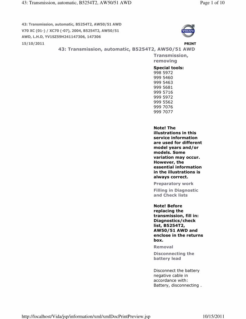
Removing engine
compartment
components
Only applies to turbo engines,
remove:
� the torque rod. See Brake fluid
reservoir, replacing
� the cover at the side of the air
cleaner (ACL) housing (applies
only to B5254T4)
� the fresh air intake hose
� the air cleaner (ACL) housing
assembly. Unhook the control
valve from the air cleaner
(ACL) housing.
Applies only to naturally
aspirated engines, remove:
� the upper torque rod in
accordance with: Brake fluid
reservoir, replacing
� the air cleaner (ACL) housing
with the intake manifold and
preheating hose
� the vacuum hoses, 2, from the
intake manifold to the control
valves
� the ground lead between the
mounting on the engine and
the bulkhead (where
applicable).
Removing
components from the
gearbox
Remove:
� the gear selector cable, use:
999 7077 to detach the ball
joint for the cable from the
lever
� the gear selector cable
mounting from the gearbox
� the oil pipe from the gearbox.
Plug the gearbox and pipe.
Unhook the mounting with the
connector for the gearbox from the
bracket for the air cleaner (ACL)
housing. Disconnect all the
connectors.
Removing the
Page 2 of 1043: Transmission, automatic, B5254T2, AW50/51 AWD
10/15/2011http://localhost/Vida/jsp/information/xml/xmlDocPrintPreview.jsp

gearbox mounting
screws
Remove the bracket with the
connectors for the heated oxygen
sensors (HO2S) and the clamp for
the cable harness from the gearbox.
Remove:
� the screws for the clamp
securing the cable harness at
the rear edge of the engine
� the nut, 1, for the bracket to
the cable harness and the
coolant hose
� the bracket for the air cleaner
(ACL) (only applies to
B5254T4)
� the 3 screws for the gearbox
and engine and the 2 screws
for the starter motor.
Tie up the cable harness.
Removing the coolant
hose from the
passenger
compartment heater
Clamp the hoses with hose clips.
Place some paper under the inner
hose connection to collect any
spilled coolant.
Turn the quick-release connector
(the inner of the 2 hoses) slightly in
the direction of the arrow so that
the lock opens.
At the same time, pull the coolant
hose straight out of the coolant
pipe.
Installing the lifting
beam and lifting hook
on the engine lifting
eyelet
Position: 999 5716 on the wheel
arch and directly above the engine
lifting eyes on the left and right-
hand sides.
Connect 999 5460 on the right-
hand side of the engine with a
clearance of 10 mm. Tighten to
Page 3 of 1043: Transmission, automatic, B5254T2, AW50/51 AWD
10/15/2011http://localhost/Vida/jsp/information/xml/xmlDocPrintPreview.jsp

light contact on the left-hand side.
Set the wheels straight.
Remove the ignition key and
activate the steering wheel lock.
Raise the vehicle.
Removing the air
baffle and splash
guard under the
engine
Remove:
� both the front wheels
� the screws for the splash
guard under the engine
� the screws for the air baffle.
Press in the catches holding the air
baffle and remove it.
Removing the screw
for the cable duct
Unhook the cable duct from the
sub-frame.
Remove the screw securing the
mounting for the ground lead in the
sub-frame
Note! Applies only to cars with
parking heaters.
Remove the 3 screws from the
heater.
Hang or tie up the heater on the
left front wing.
Detach the fuel line for the heater
from the holders on the sub-frame.
Removing the cross
members from the
body
Remove:
� the screws for the
Page 4 of 1043: Transmission, automatic, B5254T2, AW50/51 AWD
10/15/2011http://localhost/Vida/jsp/information/xml/xmlDocPrintPreview.jsp

crossmember, furthest forward,
x 4
� the brake pipe from the front
cross member
� the screws on one side, 2, and
undo the others, 2, so that the
crossmember is hanging
loosely.
Removing the screws
and nuts for the
engine pads, torque
rod
Remove:
� the screw, 1, for the front/rear
engine pad
� the screws for the torque rod.
Measuring the
position of the tie rod
in the steering gear
On one side, measure the length of
the track rod in relation to the
steering gear housing. Note the
measurement.
Exposing the steering
shaft joint
Remove the screw, 1, to the joint
between the steering gear and the
steering wheel shaft.
Press the joint up from the steering
shaft.
Detach the cable to the stepper
motor/solenoid.
Removing front
suspension
components (both
Page 5 of 1043: Transmission, automatic, B5254T2, AW50/51 AWD
10/15/2011http://localhost/Vida/jsp/information/xml/xmlDocPrintPreview.jsp

sides)
Detach the ABS cable from the
bracket in the spring strut on the left-
hand side.
Remove:
� the screw, 1, for the drive shaft,
counterholding with a
screwdriver in the brake disc
vents
� the nut for the ball joint / link
arm. Clean the exposed threads
outside the nut. Spray using
rust solvent before removing
the nut.
For steel control arm, see: Ball joint,
replacing
Remove on the left-hand side:
� the link from the anti-roll bar
� the tie rod.
Note! Counterhold using a Torx TX
40 at the ball joint pinion when
removing the nut. This is so that
the ball joint boot does not turn.
Preparations when
removing gearbox
Remove the 2 nuts from the wing
liner. Remove the support plates on
both sides.
Note! Only left-hand side.
Angle out and tie up the wing liner
to the lifting beam using a retaining
strap.
Caution! Do not forget to
protect the front fender.
Preparations for
lowering the sub-
frame
Unhook the link arms from the ball
joints on both sides. Use: 999
7076 . Install: 999 5562 . Hold the
sleeve in place with the ball joint
nut.
Bend out the spring struts and
Page 6 of 1043: Transmission, automatic, B5254T2, AW50/51 AWD
10/15/2011http://localhost/Vida/jsp/information/xml/xmlDocPrintPreview.jsp

detach the drive shafts from the
wheel hubs so that the gaiters are
not damaged. Hold the spring struts
away using a retaining strap to
obtain better space when the drive
shafts are removed.
Keep the seal on the outer constant
velocity joint housing if it falls off.
Remove the screws from the sub-
frame support plates (both sides).
Apply: 998 5972 together with: 999
5972 lightly under the right-hand
side of the sub-frame.
Slacken off the screws for the sub-
frame on the right hand side.
Ensure that the nuts are still
secured by at least 5 threads.
Remove 998 5972 .
Removing the right-
hand drive shaft
Remove the screws to the drive
shaft bearing cap and remove the
support bearing cap.
Remove the drive shaft by pulling it
straight out from the gearbox.
Note! On vehicles equipped with
AWD the drive shaft runs
through the angle gear.
Removing the left-
hand drive shaft
Remove the drive shaft from the
transmission. Use: 999 5681 .
Lowering the sub-
frame
Position the mobile jack (lightly
Page 7 of 1043: Transmission, automatic, B5254T2, AW50/51 AWD
10/15/2011http://localhost/Vida/jsp/information/xml/xmlDocPrintPreview.jsp
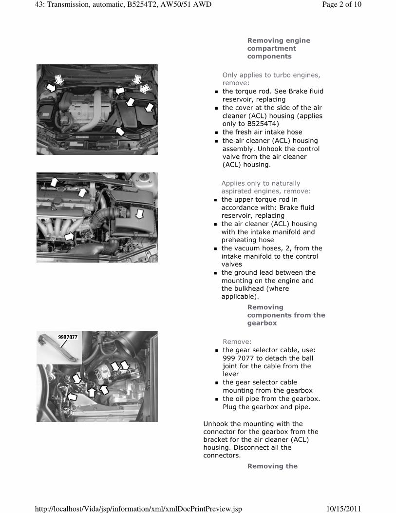
applied) under the left-hand side of
the sub-frame. Remove the sub-
frame screws. Lower the sub-frame.
Note! Check that the hoses and
electrical cables are free and
not stretched when lowering.
Remove the mobile jack and let
the frame hang freely.
Removing bevel gear
Note! Only applies to vehicles
equipped with AWD.
Remove the angle gear screws, 5.
Pull the angle gear straight out from
the gearbox.
Hang the angle gear up in an oil
pipe to the turbocharger or similar
for example.
Removing the rear
engine mounting
Remove:
� the 3 screws
� the mounting and the engine
pad.
Removing the screws
from the torque
converter
Page 8 of 1043: Transmission, automatic, B5254T2, AW50/51 AWD
10/15/2011http://localhost/Vida/jsp/information/xml/xmlDocPrintPreview.jsp

Remove the 6 screws for the torque
converter.
Turn the engine using a socket and
ratchet. Pull out the right-hand wing
liner slightly so that the crankshaft
nut can be accessed more easily.
Use a Torx TX50 socket on the
torque converter screws.
Removing the oil pipe
from the gearbox
Position a container under the pipe
terminal.
Remove:
� the 2 screws holding the pipe.
Remove the pipe from the
gearbox. Install sealing plugs
in the pipe and the gearbox.
Carefully fold the hose out of
the way
� the ground lead from the
gearbox.
Lowering the engine
and the gearbox
Lower the vehicle.
Lower the engine/gearbox on the
left-hand side with the lifting hook.
Note! Check that no hoses or
cables are being stretched or
trapped when the engine is
lowered.
Lower the engine until the lifting
hook stop can be seen in the hole on
the hook's upper part, see
illustration.
Raise the vehicle.
Installing the fixture
on the mobile jack
and gearbox
Install: 999 5463 to: 999 5972 .
Use the fixture and the plate
together with: 998 5972 .
Page 9 of 1043: Transmission, automatic, B5254T2, AW50/51 AWD
10/15/2011http://localhost/Vida/jsp/information/xml/xmlDocPrintPreview.jsp

Align: 999 5463 to the fixture and
the transmission.
Note! The support plate is
installed on the inside of the
fixture mounting lug (see
image).
Tighten the fixture with the torque
rod screws, 2.
Apply the mobile jack lightly against
the gearbox.
Removing all the
screws for the
gearbox and engine
Remove the remaining 7 screws for
the gearbox and engine.
Removing the
gearbox
Note! Ensure that the
transmission is taken straight
out in relation to the engine.
Note! Make sure that the torque
converter follows with the
gearbox and that it does not
slide off the stator shaft.
Press with a screwdriver through
one of the screw holes in the carrier
plate.
Caution! Do not pry toward the
flange rim for the flywheel
sensor.
Note! Lower the gearbox slightly
when it is being removed so that
it will pass the side member
freely.
Remove the gearbox.
15/10/2011 PRINT
Page 10 of 1043: Transmission, automatic, B5254T2, AW50/51 AWD
10/15/2011http://localhost/Vida/jsp/information/xml/xmlDocPrintPreview.jsp


![A960E AUTOMATIC TRANSMISSION · A960E AUTOMATIC TRANSMISSION GENERAL The A960E 6-speed automatic transmission [6 Super ECT (Electronic Controlled Transmission)] is used on the 4GR-FSE](https://static.fdocuments.us/doc/165x107/5e8ff69218b2bd4cae3aae4a/a960e-automatic-transmission-a960e-automatic-transmission-general-the-a960e-6-speed.jpg)