PRINCIPLES OF LIGHTNING PROTECTION
34
PRINCIPLES OF LIGHTNING PROTECTION Phillip R Tompson Chairman Novaris Pty Ltd PO Box 2010, Kingston AUSTRALIA 7050 PH: +613 6229 7233 FAX: +613 6229 9245 Email: [email protected]
Transcript of PRINCIPLES OF LIGHTNING PROTECTION

PRINCIPLES OF LIGHTNING PROTECTION
Phillip R Tompson
Chairman Novaris Pty Ltd
PO Box 2010,
Kingston AUSTRALIA 7050 PH: +613 6229 7233
FAX: +613 6229 9245 Email: [email protected]

Novaris Pty Ltd Tel: + 61 3 6229 7233 PO Box 2010, Kingston, Fax: + 61 3 6229 9245 TAS. 7050, www.novaris.com.au AUSTRALIA [email protected]
Section #: SK09 Revision: 2 Date: 01.02.08 Page: 2 of 34
Contents PRINCIPLES OF LIGHTNING PROTECTION .......................................................................... 1
1. INTRODUCTION .............................................................................................................. 3
2. THE NEED FOR LIGHTNING PROTECTION ............................................................... 4
2.1. LIGHTNING PROTECTION PRINCIPLES ............................................................... 4
2.1.1. The Lightning Discharge ....................................................................................... 4
2.2. Direct and Indirect Lightning Strikes ........................................................................... 9
2.2.1. Direct Lightning Strikes ........................................................................................ 9
2.2.2. Indirect Lightning Strikes...................................................................................... 9
3. REQUIREMENTS FOR LIGHTNING PROTECTION .................................................. 14
3.1. Structural Protection ................................................................................................... 14
3.2. Protection of Antenna Structures - towers and masts ................................................. 18
3.3. Earthing and Bonding ................................................................................................. 20
3.3.1. Station Earth ........................................................................................................ 20
3.3.2. Communications Towers..................................................................................... 21
3.3.3. Rooftop Antennas ................................................................................................ 21
3.3.4. RF Feeders........................................................................................................... 21
3.4. Surge Protection for Power Distribution ................................................................. 22
3.4.1. Incoming Mains - first stage protection .............................................................. 22
3.4.2. Main switchboard - second stage protection ....................................................... 24
3.4.3. Power Circuit Segregation .................................................................................. 25
3.4.4. External Circuit Protection .................................................................................. 26
3.4.5. Overvoltage Protection ........................................................................................ 26
3.5. Surge Protection for RF Cables .................................................................................. 27
3.6. Surge Protection for telephone / data cabling ............................................................. 29
4. LIGHTNING PROTECTION CHECK LIST ................................................................... 30
Appendix A: Table of Figures .................................................................................................. 34
Novaris Pty Ltd Tel: + 61 3 6229 7233 PO Box 2010, Kingston, Fax: + 61 3 6229 9245 TAS. 7050, www.novaris.com.au AUSTRALIA [email protected]
Section #: SK09 Revision: 2 Date: 01.02.08 Page: 3 of 34
PRINCIPLES OF LIGHTNING PROTECTION
by Phillip R Tompson BE(Hons) FIE(Aust) CPEng MIEE
NOVARIS PTY LTD PO Box 2010, Kingston AUSTRALIA 7050
PH 61 3 6229 7233 FAX 61 3 6229 9245
Email: [email protected] 1. INTRODUCTION
This paper presents a review of lightning protection principles and set out a methodology to be followed to provide a total solution to both the direct and indirect effects of a lightning strike.
The information in this volume may be used as a guide when planning lightning and surge protection for existing and future sites. Although providing basic guidelines and recommendations which will undoubtedly improve lightning immunity, it is recommended that expert assistance be sought should out the ordinary circumstances be present or a site configuration not covered by this document be encountered.
It should be remembered that the provision of lightning protection both against direct strike and indirect effects will only improve lightning immunity. It is unlikely that 100% protection can ever be achieved although attention to proper design at an early stage before equipment installation can both reduce later costs and substantially improve protection in the longer term.
Phillip Tompson is the Chairman of Novaris Pty Ltd. He holds an honours degree in Electrical Engineering from the University of Queensland, Australia. He has been practising electrical engineer for 29 years and has specialised in the field of lightning protection for the last 15 years. He is a Fellow of the Institution of Engineers, Australia, a member of the Institution of Electrical Engineers (UK) and a member of the IEEE.
He is currently the Institution of Engineers, Australia nominated representative on Australian Standards committee EL/24 responsible for the preparation of AS1768, the Australian Standard on Lightning Protection.
Novaris Pty Ltd Tel: + 61 3 6229 7233 PO Box 2010, Kingston, Fax: + 61 3 6229 9245 TAS. 7050, www.novaris.com.au AUSTRALIA [email protected]
Section #: SK09 Revision: 2 Date: 01.02.08 Page: 4 of 34
2. THE NEED FOR LIGHTNING PROTECTION
In most tropical countries lightning and storm activity is high compared to the more temperate regions of the world. For example in the equatorial belt ten degrees north and south of the equator, thunderday statistics may vary from 150 to 200 days per year.
This may be compared to typical temperate climates where the thunderdays may be around 25 or 30 per year.
Since the majority of high technology specialised military, communications, navigational and switching equipment is designed and generally manufactured in these temperate countries, scant regard is often paid to the need to protect this equipment from the devastating effects of lightning strikes whether they be direct or indirect.
For this reason lightning protection against both direct and indirect lightning strikes at critical communications and navigational aid sites in tropical regions of the world should be mandatory.
2.1. LIGHTNING PROTECTION PRINCIPLES
Knowledge of the mechanism of the lightning discharge enables an understanding of the way in which lightning detection and warning systems operate. This report investigates the discharge mechanism and discusses the principles of lightning protection and the way this is applied to the protection of structures.
2.1.1. The Lightning Discharge
The transient discharge of electric current that occurs between a negative charge centre and a positively charged region is a lightning flash. A typical flash is made up of one or more discharge components or pulses, with each pulse consisting of a negative leader stroke and a positive return stroke.

Novaris Pty Ltd Tel: + 61 3 6229 7233 PO Box 2010, Kingston, Fax: + 61 3 6229 9245 TAS. 7050, www.novaris.com.au AUSTRALIA [email protected]
Section #: SK09 Revision: 2 Date: 01.02.08 Page: 5 of 34
On a normal fine, sunny day the earth has a slight negative polarity, and the electric field so created is about 300V per meter. As a thundercloud forms, separation of electric charge in the cloud creates a surplus of negative charge in the base of the cloud and over a period of many minutes this will build up to create an electric field in the order of 10KV per meter. Imagine the electric field as essentially horizontal lines in figure 1.
Figure 1 Charge build up
---
- -
+++ ++
Charge build up in cloud
Electric fieldintensification
Positive charge on ground
Air breakdown leads tostepped leader

Novaris Pty Ltd Tel: + 61 3 6229 7233 PO Box 2010, Kingston, Fax: + 61 3 6229 9245 TAS. 7050, www.novaris.com.au AUSTRALIA [email protected]
Section #: SK09 Revision: 2 Date: 01.02.08 Page: 6 of 34
Charge build up continues until the electric field is so great that ionisation of the air occurs. As ionisation occurs, the stepped leader extends from the cloud towards ground bringing electric charge with it.
Figure 2 shows a building or other structure. The effect of this structure is to distort the electric field as it top is at earth potential. The field lines now must curl around the building, creating field intensification at the top and corners. Clearly taller the structure the greater will be the field distortion caused. In the extreme a tall slender mast or tower will cause extreme field distortion and it is clear why taller structures are more frequently struck by lightning.
+
+
+++
- - - -
Up draughts ofwarm air
Down draughtsof cold air
Negative chargecloud base
Positive chargeon top
rain
Figure 2 Development of the downward leader
Novaris Pty Ltd Tel: + 61 3 6229 7233 PO Box 2010, Kingston, Fax: + 61 3 6229 9245 TAS. 7050, www.novaris.com.au AUSTRALIA [email protected]
Section #: SK09 Revision: 2 Date: 01.02.08 Page: 7 of 34
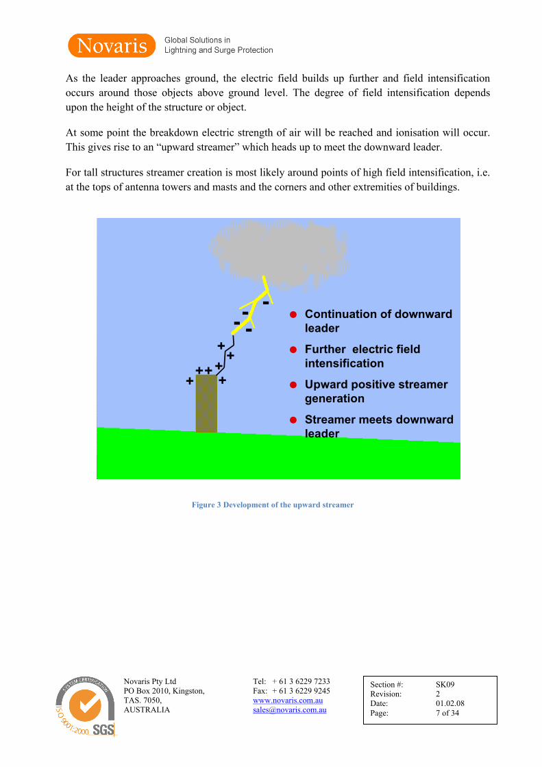
As the leader approaches ground, the electric field builds up further and field intensification occurs around those objects above ground level. The degree of field intensification depends upon the height of the structure or object.
At some point the breakdown electric strength of air will be reached and ionisation will occur. This gives rise to an “upward streamer” which heads up to meet the downward leader.
For tall structures streamer creation is most likely around points of high field intensification, i.e. at the tops of antenna towers and masts and the corners and other extremities of buildings.
----
+++ ++
Continuation of downwardleader
Further electric fieldintensification
Upward positive streamergeneration
Streamer meets downwardleader
++
Figure 3 Development of the upward streamer

Novaris Pty Ltd Tel: + 61 3 6229 7233 PO Box 2010, Kingston, Fax: + 61 3 6229 9245 TAS. 7050, www.novaris.com.au AUSTRALIA [email protected]
Section #: SK09 Revision: 2 Date: 01.02.08 Page: 8 of 34
One of the upward streamers will meet the downward leader and complete the ionisation path. The electric charge is then discharged via this path and the so called “return stroke” current flows. This characterises a direct lightning strike.
-
-
--
+++
+
Positive upward streamermeets the downwardleader
Conducting path forms
Potential is equalised bythe "return stroke"
Visible lightning flash
+
+
--
Figure 4 The return stroke

Novaris Pty Ltd Tel: + 61 3 6229 7233 PO Box 2010, Kingston, Fax: + 61 3 6229 9245 TAS. 7050, www.novaris.com.au AUSTRALIA [email protected]
Section #: SK09 Revision: 2 Date: 01.02.08 Page: 9 of 34
2.2. Direct and Indirect Lightning Strikes
2.2.1. Direct Lightning Strikes
All world standards relating to lightning protection cover the topic of structural lightning protection extensively. A direct strike to a building or structure will seek a path to ground either via the structure’s lightning protection system or via any other metallic path via a series of flashovers which may be quite unpredictable.
As well as direct strikes to buildings and structures, lightning may directly strike power lines, antennas, antenna feeders and overhead telephone cables as well as mechanical services like water and gas piping.
Direct lightning strikes may be transmitted within the building via these external metallic services. They will seek a path to ground often via the equipment to which they may be connected. The aim then must be to intercept these impulses as they enter the building and bypass them to earth.
2.2.2. Indirect Lightning Strikes
As well as direct lightning strikes, indirect effects can also be damaging. For example if lightning strikes a building or any of the services mentioned above, transient overvoltages may be caused through resistive, inductive and capacitive coupling. The following serves to illustrate this point:
Resistive coupling is the most common cause of transient overvoltages and it affects both underground and overhead lines. Resistively coupled transients occur when a lightning strike raises the electrical potential of one or more of a group of electrically interconnected buildings, or structures like a communications tower and its associated equipment building.
• Common examples of electrical interconnections are: • power feeds from substation to building • building to building power feeds • power supplies from the building to external lighting, CCTV or security systems • telephone lines from the exchange to the building • telephone extensions between buildings • data and LAN connections between buildings • RF signal cables from antennas and towers to buildings • signal or power lines from a building to field based sensors

Novaris Pty Ltd Tel: + 61 3 6229 7233 PO Box 2010, Kingston, Fax: + 61 3 6229 9245 TAS. 7050, www.novaris.com.au AUSTRALIA [email protected]
Section #: SK09 Revision: 2 Date: 01.02.08 Page: 10 of 34
Figure 5 shows two buildings. Each contains electronic equipment which is connected to earth through its mains supply. A data communications line connects the two pieces of equipment and the two separate earths.
Figure 5 Resistive coupling through a data line
A nearby lightning strike will inject current into the ground. The current flows away from the strike point. In this example the earth electrode, electrical cables and the circuitry of the damaged electronic equipment are all better conductors than the soil. As the current attempts to flow, devastating transient overvoltages can be seen across the sensitive components of the equipment.
Resistively coupled transients can occur when separately earthed structures are only metres apart. Resistive coupling affects both underground and overhead cables.
Figure 6 provides an example of how resistively coupled transient overvoltages can occur on a mains power supply.
Figure 6 Resistive coupling through the live, neutral and earth conductors of a mains power supply

Novaris Pty Ltd Tel: + 61 3 6229 7233 PO Box 2010, Kingston, Fax: + 61 3 6229 9245 TAS. 7050, www.novaris.com.au AUSTRALIA [email protected]
Section #: SK09 Revision: 2 Date: 01.02.08 Page: 11 of 34
Inductive coupling is a magnetic field transformer effect between lightning and cables. A lightning discharge creates a very high current flow and this current creates an electromagnetic field around it. If power or data cabling passes through this magnetic field, voltage will be picked up or induced into the cable.
This frequently occurs when lightning discharges close to overhead power lines, telephone cables, RF antennas or their feeders. (Figure 7). It is not just lightning strikes from cloud to ground which can induce these voltages. Cloud to cloud strikes can also induce similar effects, albeit to a lesser extent generally.
Figure 7 Inductive coupling
The same thing occurs when a building’s lightning protection scheme is struck. The lightning current flows to earth through the building’s down conductors. The resulting magnetic field may well couple to cabling within the building, inducing transient overvoltages into it. (Figure 8).
Capacitive coupling. Where long lines are well isolated from earth they can rise to high voltages due to the capacitance between them and the charged thunder cloud. If the voltage on the line rises beyond the breakdown strength of the devices at either end, damage will result.
For these reasons lightning protection against both direct and the indirect effects caused by induction must be provided.

Novaris Pty Ltd Tel: + 61 3 6229 7233 PO Box 2010, Kingston, Fax: + 61 3 6229 9245 TAS. 7050, www.novaris.com.au AUSTRALIA [email protected]
Section #: SK09 Revision: 2 Date: 01.02.08 Page: 12 of 34
Figure 8 Inductive coupling from a lightning downconductor
When planning equipment installations it is advisable to avoid runs of power and telephone / data cabling parallel to lightning downconductors. Placing these cables in metal ducts provides excellent shielding and will overcome this problem.
Lightning protection must be approached from a systems point of view. All parts of the systems must be complete for the overall protection scheme to be effective. The following parts make up the overall system approach:
• Structural protection against direct lightning strike. • Protection of antenna structures - towers and masts. • Earthing and bonding. • Surge protection for power distribution. • Surge protection for RF cables. • Surge protection for telephone / data cabling.
In providing an overall protection scheme it is useful to consider the concept of a “protection boundary”. The protection boundary defines the boundary over which we wish to prevent or at least attenuate lightning energy. The boundary may be the perimeter of the building under consideration - thus all protection for services should be placed at this boundary.
Alternatively it may be necessary to define multiple boundaries where lightning energy is removed progressively. For example a generator room containing incoming mains (PUB) may be the first boundary where high energy surge diverters may be placed.

Novaris Pty Ltd Tel: + 61 3 6229 7233 PO Box 2010, Kingston, Fax: + 61 3 6229 9245 TAS. 7050, www.novaris.com.au AUSTRALIA [email protected]
Section #: SK09 Revision: 2 Date: 01.02.08 Page: 13 of 34
The secondary boundary may be the equipment room switchboard where lower energy surge diversion equipment with additional filtering may be added to remove residual energy.
Figure 9 shows a typical example of a communications installation involving multiple protection boundaries dividing, in this application, 4 protection zones. These are:
• Zone 0: The external environment • Zone 1: Immediately inside the building divided by a boundary defined as the external
walls of the building • Zone 2: Inside a screened room with the boundary defined as the screened room walls. • Zone 3: Inside equipment cabinets with the boundary defined as the cabinet itself.
Figure 9 The concept of multiple boundaries and zones
Overvoltage. One consequence of a lightning strike to a power line is a disturbance in the power supply voltage. Additionally poor voltage regulation on long lines, particularly at mountain top communications sites can result in extensive damage to equipment. Often this damage is blamed upon lightning strikes. A prolonged mains overvoltage can cause damage to equipment and to surge protection devices which, without proper design, cannot cope with excessive voltage.
For this reason consideration must be given to voltage regulating equipment or overvoltage disconnect equipment. Automatic voltage regulators may be appropriate at large, major centres but where backup generators and/or battery backup are provided overvoltage disconnects are a more economical solution. These too must be properly design so that they do not succumb to lightning surge voltages.
Novaris Pty Ltd Tel: + 61 3 6229 7233 PO Box 2010, Kingston, Fax: + 61 3 6229 9245 TAS. 7050, www.novaris.com.au AUSTRALIA [email protected]
Section #: SK09 Revision: 2 Date: 01.02.08 Page: 14 of 34
3. REQUIREMENTS FOR LIGHTNING PROTECTION
This section provides a systematic approach to lightning protection giving consideration to the concept to the lightning protection boundary.
3.1. Structural Protection
To decide the level of protection required for buildings it is necessary to categorise the type of building and its contents. Under all conditions lightning protection is necessary to provide protection to personnel working in buildings. Additional protection may be necessary to protection sensitive equipment inside these buildings.
• Type I Building is defined as a building with metal cladding on all walls and the roof. This provides a screened room environment for equipment inside. If all the cladding and roofing is satisfactorily bonded together lightning can strike any part of the building and flow to ground via the cladding. This provides almost total protection with the building acting as a Faraday cage. Most lightning protection standards recommend that no other protection is required. Steel framed buildings of reinforced concrete buildings with metal cladding approximate this ideal. For such a building without electronic equipment only basic surge protection such as main switchboard surge diverters and telephone protection on MDF is necessary.
• Type Ia Building is similar to type I except that it contains electronic equipment and
associated equipment such as outdoor antenna, sensors etc. In this case full protection is necessary and the protection boundaries must be established. All services must be protected.
• Type II Building is constructed from reinforced concrete or steel framed with no
metal cladding. • Type IIa Building is similar to type II except that it contains electronic equipment and
associated equipment such as outdoor antenna, sensors etc. In this case full protection is necessary and the protection boundaries must be established. All services must be protected.
• Type III Building is constructed from materials substantially free of metal. • Type IIIa Building is similar to type II except that it contains electronic equipment
and associated equipment such as outdoor antenna, sensors etc. In this case full protection is necessary and the protection boundaries must be established. All services must be protected.

Novaris Pty Ltd Tel: + 61 3 6229 7233 PO Box 2010, Kingston, Fax: + 61 3 6229 9245 TAS. 7050, www.novaris.com.au AUSTRALIA [email protected]
Section #: SK09 Revision: 2 Date: 01.02.08 Page: 15 of 34
Protection requirements
Type I Buildings: All cladding and roofing sheet must be bonded together. No other form of lightning protection is necessary, the cladding both acts as air terminal and downconductor. The cladding must be connected to the earthing system.
Type II Buildings: During construction connect all steel frames together and bond these to the roofing if metal. The steel frames may act as the downconductors. Generally no other downconductors are necessary. The same procedure should be applied to reinforced steel concrete buildings. Bond the reinforcing. These recommendations are in accordance with most lightning protection standards.
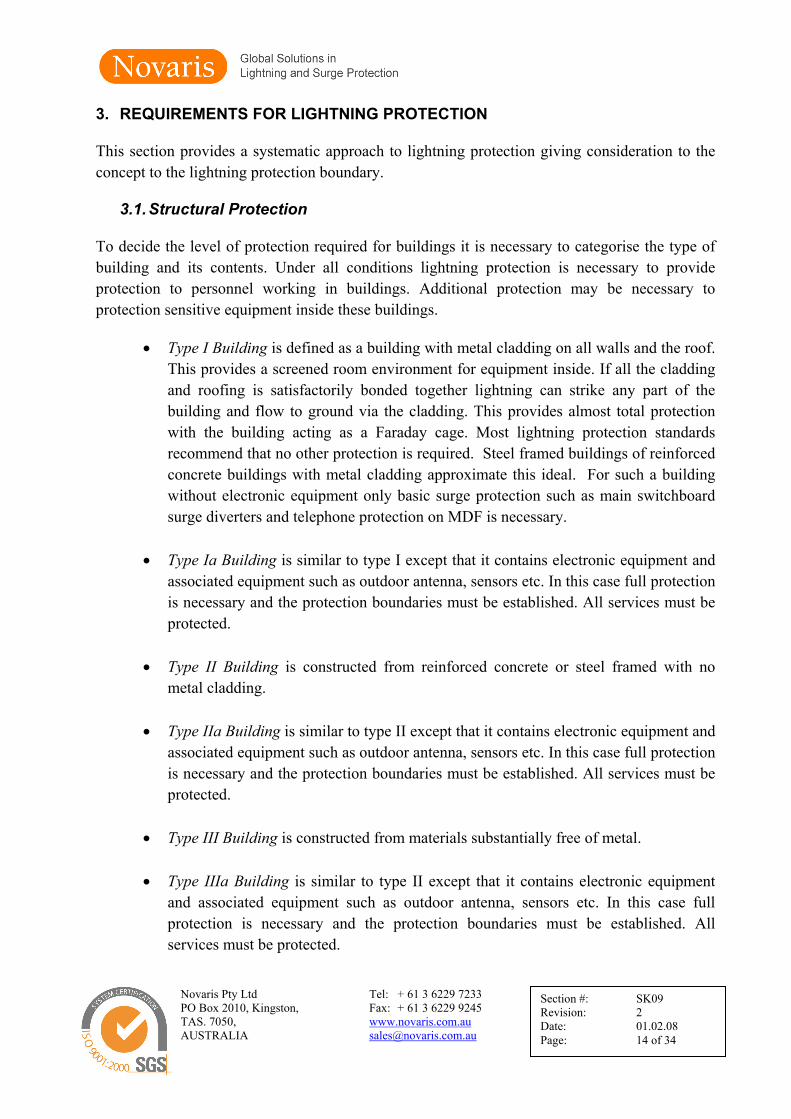
For non metallic roofs, apply the rolling sphere analysis method, illustrated in figure 10, to predict lightning attachment. Install lightning finials as described in the relevant standard. Air terminals may be copper strap, horizontal or a combination of copper strap and vertical finials. Railings and other metal fixtures must be bonded to the lightning protection system. Railings may be used as air terminals as shown in figure 11.
The rolling sphere analysis may also be used to design placement of finials of large flat roofs. Figure 12 illustrates how this can be done.
When retrofitting lightning protection, if steel frames and reinforcing cannot be bonded, threat the building as type III.
Type III Buildings: Air terminals to be designed as for type II buildings. Downconductors must be installed externally to the building and earthed to the building earth. Downconductors shall be placed on all corners of the building plus at 10 metre intervals along each wall.
A lightning stroke counter should be fitted in at least one downconductor to measure lightning strike activity. A suitable strike counter would rely upon inductive pick up and not need to be placed in circuit. This adds to reliability of the downconductor by minimising joints. The strike counter should be waterproof with a reset button inaccessible without the use of tools and the unit powered by a long life battery of minimum 10 years life.
Novaris Pty Ltd Tel: + 61 3 6229 7233 PO Box 2010, Kingston, Fax: + 61 3 6229 9245 TAS. 7050, www.novaris.com.au AUSTRALIA [email protected]
Section #: SK09 Revision: 2 Date: 01.02.08 Page: 16 of 34
Figure 10 The rolling sphere analysis technique
Figure 11 Example of Parapet Railing employed as air termination in concrete reinforced buildings

Novaris Pty Ltd Tel: + 61 3 6229 7233 PO Box 2010, Kingston, Fax: + 61 3 6229 9245 TAS. 7050, www.novaris.com.au AUSTRALIA [email protected]
Section #: SK09 Revision: 2 Date: 01.02.08 Page: 17 of 34
Figure 12 Zones of protection for a flat roof
Non Conventional Protection
There is a range of lightning terminals available which claim enhanced protection over conventional terminals. Many conventional lightning protection standards do not recognise these terminals. French standard NF 17-102 applies to Early Streamer Emission (ESE) terminals. By using the principles outlined in this standard it is possible to reduce the number of lightning terminals required to protect a given structure. However caution is advised as there is considerable controversy about the effectiveness of these enhanced lightning terminals especially over large flat roofed structures.
There are also terminals, called dissipation arrays, which claim to prevent lightning strikes. There is good evidence that shows such terminals are completely ineffective and are to be avoided.

Novaris Pty Ltd Tel: + 61 3 6229 7233 PO Box 2010, Kingston, Fax: + 61 3 6229 9245 TAS. 7050, www.novaris.com.au AUSTRALIA [email protected]
Section #: SK09 Revision: 2 Date: 01.02.08 Page: 18 of 34
3.2. Protection of Antenna Structures - towers and masts
Any lightning strike to any structure will cause a potential gradient to be developed between the ground and the top of the structure. The magnitude of this potential will depend upon the height of the structure which determines downconductor length. Although the resistance of downconductors contributes to this potential rise, it is the inductance of downconductors which ultimately determines the potential rise.
This potential rise can NEVER be eliminated, only minimised, by utilising multiple downconductors.
A - Steel Towers
On steel towers the most efficient downconductors are the legs of the tower itself. Extra downconductors in the form of copper strap or cables are useless. In protecting steel towers install a finial at the top of the tower, a minimum of 1.5 metres above the highest antenna or other equipment, for example obstruction lights. The aim is to prevent direct lightning strikes to the antennas if they are not designed for direct strike. The finial needs to be of no special construction. A tapering top is recommended. It may be constructed of galvanised steel, stainless steel or copper. After a number of strikes the galvanising on the steel may be damaged, copper will overcome this problem. At sites where the tower may be called upon to provide protection for an extensive area, an ESE terminal may be considered.
B - Wooden Towers
Wooden towers pose a particular problem. If proper downconductors are not installed a direct strike will find a ground path via the wooden legs - this may cause a fire hazard. Alternatively the strike will flow to ground via antenna feeders. Install a finial as described above and downconductors of minimum 25 x 3 mm copper strap down each leg of the tower.
C - HF Antennas
HF antennas are likely to receive many direct strikes to their radiating elements. Those elements that are directly grounded are of no concern. Radiating elements should have spark gap arresters fitted to dissipate lightning energy to ground. A typical spark gas arrester is shown in figure 13. These arresters are suitable for transmitting antennas.
Novaris Pty Ltd Tel: + 61 3 6229 7233 PO Box 2010, Kingston, Fax: + 61 3 6229 9245 TAS. 7050, www.novaris.com.au AUSTRALIA [email protected]
Section #: SK09 Revision: 2 Date: 01.02.08 Page: 19 of 34
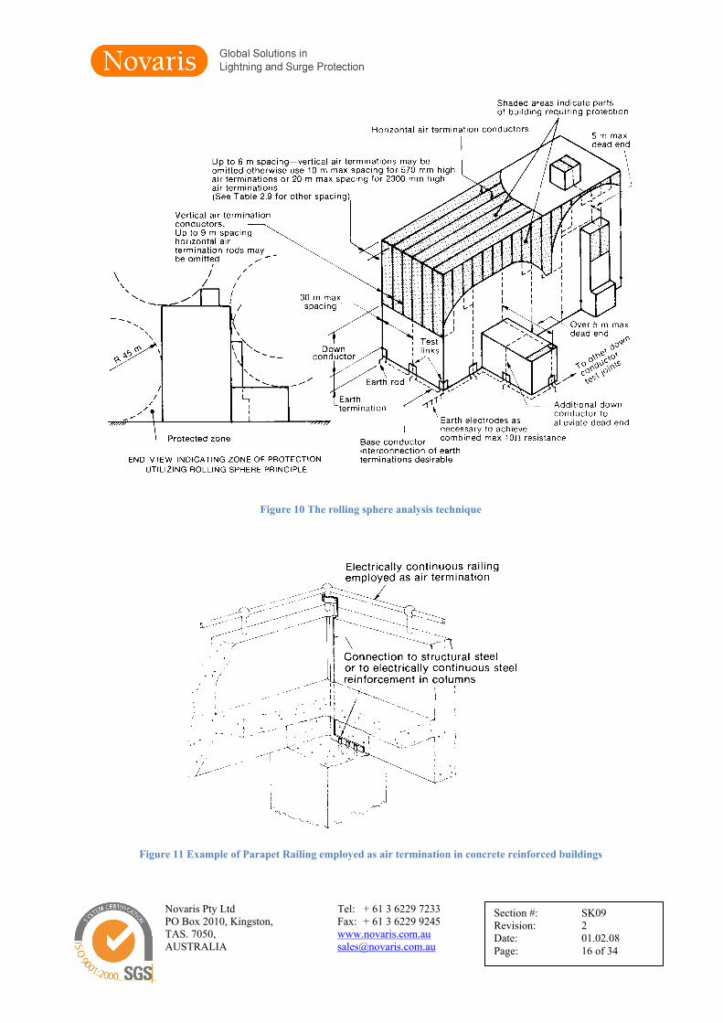
Receiving antennas are better protected with gas filled arresters in place of spark gaps. Gas filled arresters have lower and more predictable flashover voltages. These units are not suitable for high power transmitting applications. Such arresters should have a surge rating of 150KA for an 8/20us impulse since they must conduct a direct lightning strike as well as induced currents. A typical arrester is shown in figure 14.
D - Rooftop Antennas
Antennas on rooftops must be bonded to the building lightning protection system. For yagi and other similar types mount these on an earthed mast with the mast at least 1.5 metres above the antenna.
For whip antennas, there are two alternatives. Provide no protection and accept the risk of a direct strike. Alternatively provide vertical masts in proximity to afford protection. The rolling sphere construction may be used to place such masts. Horizontal wires between masts will enhance protection.
Note: The presence of earthed masts near vertical radiators may affect the radiation pattern.
Figure 13 Spark gap arrester
Figure 14 150KA gas filled surge arrester

3.3.
In the clightnin
At a co3 mm beach dothat lightouch pachieveterminaflows ustep and
NovariPO BoxTAS. 7AUSTR
. Earthing
3.3.1. Sta
completion ng strike to g
mmunicatioburied coppownconducthtning currepotentials aned by ensuration is limiuniformly ind touch pote
s Pty Ltd x 2010, Kingsto
7050,RALIA
and Bond
ation Earth
of a lightnground.
ons site a peper strap sutor install aents are discnd the risking that theited by a sun all directiential.
on,
ding
ning strike,
erimeter earurrounding an earth rodcharged into
k of side flae potential wufficiently lons away f
Figure 15
Tel: + 61 3 Fax: + 61 3 www.novarisales@novar
an earthing
rth ring shothe building
d. The desigo the earth iashing to mwith respeclow resistanfrom the str
5 Step and touc
6229 7233 6229 9245 s.com.au ris.com.au
g system m
ould be instag. At each gn of the ein such a m
metal in or ct to the gennce to earthructure. Fig
ch potentials
SectionRevisioDate: Page:
must be pro
alled. This corner andarth termin
manner that waround a s
neral mass h and that tgure 15 illus
n #: SKon: 2
0 20
ovided to di
should cond at the termnations shouwill minimistructure. Tof earth at
the dischargstrates the m
K09
1.02.08 0 of 34
issipate the
sist of 25 xmination ofuld be suchise step andThis can be
each earthged currentmeaning of
x f h d
h t f
Novaris Pty Ltd Tel: + 61 3 6229 7233 PO Box 2010, Kingston, Fax: + 61 3 6229 9245 TAS. 7050, www.novaris.com.au AUSTRALIA [email protected]
Section #: SK09 Revision: 2 Date: 01.02.08 Page: 21 of 34
The station earth provides the basic earthing structure. This must be bonded to the mains earth, the telecommunications earth and any other earthing system.
Lightning protection standards recommend 10 ohms or less for lighting protection earth. A building earth at a secure communications should have an earth resistance of 5 ohms or less.
It is often believed that the lowest earth resistance will provide the most effective lightning protection. In fact this requirement is really secondary to the need to bond all metallic structures and services together to produce an equipotential plane so that everything rises in potential together. As long as this is carried out equipment at a site can still be successfully protected with earth resistances of 50 or even 100 ohms.
Direct bonding is permitted by many lightning protection standards and is the only preferred method. Otherwise bond all earthing systems via gas filled arresters with rating 150KA for an 8/20us impulse. (Figure 14). EARTH POTENTIAL RISE CAN NEVER BE ELIMINATED. That is why bonding is essential.
3.3.2. Communications Towers
Provide an earthing system for communications masts and towers. For microwave towers containing VHF, UHF and microwave antennas located adjacent to communications buildings, connect each leg of the tower to an earth electrode. Bond the tower earthing system to the building earth via a 25 x 3 mm buried copper strap.
Antennas masts and supports for HF antennas located in an antenna farm may be earthed via single earth rod.
3.3.3. Rooftop Antennas
Bond the support masts and ground planes to the rooftop lightning protection system.
3.3.4. RF Feeders
Bond the cable sheaths of RF coaxial feeders to tower structural members at the point they leave the tower to the horizontal cable runway.
Bond feeder sheaths to the cable panel at the point of entry to the building. This is a defined protection boundary. The cable entry plate should consist of a metallic plate fitted with suitable glands; the plate must be bonded to the perimeter earth ring.
Treat the screens of all shielded cables in exactly the same manner as above.

Novaris Pty Ltd Tel: + 61 3 6229 7233 PO Box 2010, Kingston, Fax: + 61 3 6229 9245 TAS. 7050, www.novaris.com.au AUSTRALIA [email protected]
Section #: SK09 Revision: 2 Date: 01.02.08 Page: 22 of 34
3.4. Surge Protection for Power Distribution
A systems approach to power surge protection must be applied to the protection of power services. Surge voltages and energies may be very high should a power line receive a direct strike.
Protection devices must be able to tolerate the effects of both direct and indirect (or induced) overvoltages.
3.4.1. Incoming Mains - first stage protection
Install high energy surge diverters on incoming mains. These should be metal oxide varistor types preferably utilising redundant segment configuration. This configuration allows possible degradation to be monitored by local and remote alarms. Alternatively spark gap type arresters can be considered. These have extra high surge ratings and good high voltage withstand.
All diverters whether single or three phase MUST include protection for the neutral which must be treated as another active conductor with respect to surge protection. Only in countries where the multiple earth neutral system is used is neutral protection unnecessary. Most 230/400V three distribution systems use the TT system which makes neutral protection essential.
A suitable rating is from 80kA to 200kA per phase for an 8/20us impulse. This depends upon location and the configuration of the incoming power feed. Figure 16 shows the maximum surge voltage and currents likely to be encountered in location categories A, B and C in a distribution network.

Novaris Pty Ltd Tel: + 61 3 6229 7233 PO Box 2010, Kingston, Fax: + 61 3 6229 9245 TAS. 7050, www.novaris.com.au AUSTRALIA [email protected]
Section #: SK09 Revision: 2 Date: 01.02.08 Page: 23 of 34
Based upon this information it is possible to appropriately size the rating of surge arresters used in any of these locations. Table 1 shows recommended sizing for metal oxide based surge arresters commensurate with long life and reliability.
Area 1 Area 2 Area 3 Area 4
Category Cat A Cat B Cat C Cat D Thunder days Td <30 Td >30 Td <30 Td >30
Underground 8 kA 16 kA 40 kA 80 kA 120 kA 160 kA Overhead 8 kA 16 kA 80 kA 120 kA 160 kA 200 kA
Table 1 Recommended surge rating for location categories A, B and C
Surge diverters must be installed between each phase line, neutral and earth. Proper installation is vital. Leads must be short, no longer than 300mm and the earth connection MUST connect direct to chassis rather than via long earth conductors. A typical three phase configuration is shown in figure 16.
High energy surge diverters should be installed on the incoming mains. In typical communications installations with back up diesel generator power these diverters would be located in the switchover cubicle generally located in the generator room.
ElectrodeEarth
L3L2L1E N
Alternative Arresterconnections to loadside of main switch
MULTIMOV
L3
N
L1
L2
LinksActive
Supply Authority'sService Fuses
SD3xxx/N
E
Main Switch
Figure 16 Configuration of redundant segment surge diverter, three phase for TT systems

Novaris Pty Ltd Tel: + 61 3 6229 7233 PO Box 2010, Kingston, Fax: + 61 3 6229 9245 TAS. 7050, www.novaris.com.au AUSTRALIA [email protected]
Section #: SK09 Revision: 2 Date: 01.02.08 Page: 24 of 34
3.4.2. Main switchboard - second stage protection
On main switchboards install series connected power surge filters. These further attenuate the incoming surge energy to a safe level for electronic equipment. Filters should be configured with line side metal oxide varistors, series LC filter with a current rating equal to the main switchboard capacity and a final stage of metal oxide varistors.
Filters with rated let through voltages of less than 500V peak for a category C (ANSI standard C62.41) impulse are recommended.
Filter surge rating on the line side should be no less than 80KA to provide long life when used in conjunction with first stage surge diverters.
Figure 17 shows a typical filter configuration suitable for this application.
EarthElectrode
E
Surge FilterPower Line
E
(Optional)Circuit Breaker
Main Switch LINEL1L1
Service FusesSupply Authority
L3
N
L3
N
L2L2
LOAD
N
L1
L3
L2
Neutral
Figure 17 Typical multistage power line surge filter for TT distribution systems
Novaris Pty Ltd Tel: + 61 3 6229 7233 PO Box 2010, Kingston, Fax: + 61 3 6229 9245 TAS. 7050, www.novaris.com.au AUSTRALIA [email protected]
Section #: SK09 Revision: 2 Date: 01.02.08 Page: 25 of 34
3.4.3. Power Circuit Segregation
Identify all other power circuits which cross the boundary and feed loads outside the building or on the building external walls. Examples include:
• security lights • perimeter lights • alarm systems • security cameras • power to external sources like antenna rotators • power to tower lighting
All external AC circuits must be segregated and fed via a separate distribution board. This board must be protected with a power surge filter to prevent incoming surge energy on these cables from entering the equipment room.
This distribution board must be fed directly from the main switchboard, and not from any other distribution board within the equipment building.
The filter must have a current rating equal to the capacity of the distribution board. Surge rating should be minimum 80KA or 120KA if there are extensive runs of overhead cable.
In this application, the LINE side of the filter must face the external circuit. The LOAD side faces the switchboard.

Novaris Pty Ltd Tel: + 61 3 6229 7233 PO Box 2010, Kingston, Fax: + 61 3 6229 9245 TAS. 7050, www.novaris.com.au AUSTRALIA [email protected]
Section #: SK09 Revision: 2 Date: 01.02.08 Page: 26 of 34
3.4.4. External Circuit Protection
The installation of power surge protection within the structural boundary effectively protects all equipment inside building enclosure.
All external loads must now be considered. These may be grouped as follows:
• security and perimeter lights
If it is deemed necessary to protect actual light fixtures, install surge diverters from line and neutral to ground as close as possible to the light to be protected.
• alarm systems and security cameras
Alarm systems and cameras powered from the main building require protection in the form of power surge filters at the load point. The filter must have a current rating equal to the capacity of the connected load. Surge rating can be 40KA for underground feeds.
• power to external sources like antenna rotators
Antenna rotators generally contain electronic controls and if mains powered require power surge filter protection installed at the rotator control box. The filter must have a current rating equal to the capacity of the connected load. Surge rating can be 40KA for underground feeds.
• power to tower lighting
When a tower which has lighting is struck by lightning, large voltages will be induced into the power cabling. Surge protection at the building will prevent the surge energy entering the building. Protection is required at the base of the tower with surge diverters. These divert induced energy to ground, keeping the effective potential of the lighting cable at the same potential as the tower. This prevents cable flashover and consequent damage to cables. Surge rating can be 40KA for underground feeds.
3.4.5. Overvoltage Protection
Where overvoltage protection is fitted it should be installed immediately after the first stage incoming power surge diverters and prior to the generator sensing equipment. Novaris overvoltage relays comprise a voltage sensing relay with adjustable over and under volts limits as well as fixed or adjustable hysteresis. The relay controls a contactor which connects or disconnects the power. There is generally no need to interface this to the generator control. The generator phase failure relay will respond to the loss of power and start the generator in the normal manner.

Novaris Pty Ltd Tel: + 61 3 6229 7233 PO Box 2010, Kingston, Fax: + 61 3 6229 9245 TAS. 7050, www.novaris.com.au AUSTRALIA [email protected]
Section #: SK09 Revision: 2 Date: 01.02.08 Page: 27 of 34
3.5. Surge Protection for RF Cables
RF coaxial cables and waveguides form a direct path from antenna to equipment for the entrance of direct and induced lightning current. There are two requirements:
• Bonding
The aim of bonding waveguides and coaxial feeders is to divert lightning energy to ground from the outer conductor of the coaxial feeder or waveguide itself.
Bonding, the action of electrically connecting the outer conductor to ground, must be applied at the point where the cable leaves the tower and where the cable enters the building. Figure 18 illustrates required bonding points.
Figure 18 Waveguide and coaxial feeder bonding points
Bonding points for waveguideand coaxial feeder

Novaris Pty Ltd Tel: + 61 3 6229 7233 PO Box 2010, Kingston, Fax: + 61 3 6229 9245 TAS. 7050, www.novaris.com.au AUSTRALIA [email protected]
Section #: SK09 Revision: 2 Date: 01.02.08 Page: 28 of 34
• Surge protection
As well as the outer conductors of coaxial feeders the inner conductors must also have protection applied to divert energy on the inner conductor to ground. The application of surge protection to UHF and microwave circuits is limited by frequency, return loss and insertion loss considerations. Typical coaxial surge protectors consist of a fast acting gas filled arrester connected between line and ground. Figure 19 shows a typical coaxial surge protector for type N connectors. This is a bulkhead mounting type.
Arrester flashover voltage should equal twice the peak line voltage. Example in a 50 ohm line with 50W transmitter, peak voltage = 70.7V. Minimum recommended gas arrester BV = 140V. Nearest value = 230V. Surge rating should be 20KA for an 8/20us impulse.
Gas filled arresters are unsuitable for high power HF and VHF transmitters (>= 1KW) unless the transmitters incorporate return power shutdown circuitry. A gas filled arrester once fired will remain in the conducting state by the presence of RF energy. This will destroy the arrester unless the transmitter has shutdown circuitry which detects the impedance discontinuity.
Alternatively utilise spark gap arresters with arc detection and shutdown circuitry.
For microwave link equipment an alternative and more effective solution is the quarter wave stub protector. These units must be tuned to the frequency in use but are capable of reasonably large bandwidth. For example a quarter wave stub protector centred on 2.4GHz has a usable bandwidth of +-100MHz. Figure 20 shows a typical unit.
Figure 19 Coaxial surge arrester
Figure 20 Quarter wave stub protector

Novaris Pty Ltd Tel: + 61 3 6229 7233 PO Box 2010, Kingston, Fax: + 61 3 6229 9245 TAS. 7050, www.novaris.com.au AUSTRALIA [email protected]
Section #: SK09 Revision: 2 Date: 01.02.08 Page: 29 of 34
3.6. Surge Protection for telephone / data cabling
All data, control and telephone cables entering and leaving the communications building require protection. The protection must be placed at the protection boundary and the protective earth connected to station earth. The aim is to divert energy at the boundary.
Data circuits require protection dependent upon their operating voltages and currents. Multistage series connected transient barriers should be employed. Figure 21 shows a typical schematic of suitable protection devices.
Figure 21 Multistage surge protector
Surge rating should be 20KA for an 8/20us impulse and the clamping voltage greater than the peak operating voltage.
Telephone lines require protection at the MDF. The protection should be multistage, when used with digital solid state telephone switches. Configuration will depend upon the termination method, eg KRONE®*, ADC, Reiche etc. Protect all incoming lines and external extensions. Generally internal extensions require no protection.
LAN systems require specialised protection specific to the LAN configuration. LAN line cards are particularly sensitive to transient overvoltage’s and MUST be protected. Specialised protectors are available for the following protocols:
• RS232 in both DB9 and DB25 connector types • RS485 and RS422 in DIN rail and DB9 configuration • Thin Ethernet with in line and protected T BNC configuration • Thick Ethernet with in line N type and DB15 AUI configuration • RJ45 for UTP with hub protectors and individual terminal protectors
Ensure all LAN type protectors do not inhibit LAN performance. Only choose CAT5 UTP protectors.
* KRONE®
is a trademark of Krone GmbH, Germany
gasarrester
MOVs suppressordiodes
L1
L2
GNDGND
E1
E2

Novaris Pty Ltd Tel: + 61 3 6229 7233 PO Box 2010, Kingston, Fax: + 61 3 6229 9245 TAS. 7050, www.novaris.com.au AUSTRALIA [email protected]
Section #: SK09 Revision: 2 Date: 01.02.08 Page: 30 of 34
4. LIGHTNING PROTECTION CHECK LIST
Site Name:………………………………………… Date:……/………/………
Check List Comply Needed Comment
Yes/No Yes/No 1. Structural Protection Define type of building I, Ia, II, IIa, III, IIIa • For Type I are all cladding and roofing sheets bonded
and earthed to structural earthing system? • For Type II are steel frames bonded to roof sheets
and structural earth? Auxiliary protection in accordance with rolling sphere design?
• For Type III are air terminals in accordance with rolling sphere design?
• Is lightning stroke counter fitted?
2. Antenna Structures - towers and masts Is there a communications tower present? • Is a lightning finial fitted above the highest antenna? • Is a finial and downconductors on each leg fitted to
wooden towers? • Do HF antennas have spark gaps fitted? • Are finials fitted to HF masts?
Are there rooftop antennas? • Are the rooftop antennas bonded to the building
lightning protection? • Are spare antennas available? • Are masts and catenary wire protection an option?
3. Earthing and Bonding Is there a station earth? • Are there sufficient downconductors terminating on
the earthing system? • Does the earth run around the perimeter of the
building? • Is the earth resistance less than 5 ohms? • Is the perimeter earth bonded to the mains (PUB)
earth and other earthing systems? • Are earth clamps in use if direct bonding is
insufficient?
Is there a communications tower? • Are the legs of the tower earthed? • Is the tower earth less than 10 ohms? • Is the tower bonded to the perimeter earth?

Novaris Pty Ltd Tel: + 61 3 6229 7233 PO Box 2010, Kingston, Fax: + 61 3 6229 9245 TAS. 7050, www.novaris.com.au AUSTRALIA [email protected]
Section #: SK09 Revision: 2 Date: 01.02.08 Page: 31 of 34
Check List Comply Needed Comment
Yes/No Yes/No 4. Surge Protection for Power Distribution Does the site have diesel backup? • Are MOV type redundant segment surge diverters
installed on the incoming mains? • Is the surge rating sufficient? • Is the neutral treated as other conductors for surge
protection? • Are the surge diverter connecting leads sufficiently
short to be effective (<=300mm)? • Is the earth return of the surge diverter connected
directly to frame?
Is surge protection fitted to the main switchboard? • What is the rating of the incoming supply? • Is it single or three phase? • Is a power surge filter of sufficient rating (80KA per
phase) fitted? • If no diesel backup and main switchboard is PUB
point of entry is surge rating sufficient (>=120KA per phase)?
Is a separate distribution board allocated to external circuits?
• are security lights installed? • are perimeter lights installed? • are alarm systems installed? • are security cameras fitted? • are there external powered antenna rotators? • is there power fed to tower lighting?
Does the external services DB have a power surge filter?
• Is a power surge filter of sufficient rating (80KA per phase) fitted?
• If overhead cables is the surge filter of 120KA per phase rating?
External services • if necessary, are surge diverters fitted to individual
lights? • are power surge filters fitted to external alarm
systems and security cameras? • are power surge filters fitted to external antenna
rotators? • are surge diverters (40kA) fitted to base of towers and
masts with lighting?

Novaris Pty Ltd Tel: + 61 3 6229 7233 PO Box 2010, Kingston, Fax: + 61 3 6229 9245 TAS. 7050, www.novaris.com.au AUSTRALIA [email protected]
Section #: SK09 Revision: 2 Date: 01.02.08 Page: 32 of 34
Check List Comply Needed Comment
Yes/No Yes/No 5. Surge Protection for RF Cables Are waveguides and coaxial feeders used at the site?
• are cable sheaths and waveguides bonded at the point they leave the tower?
• are cable sheaths and waveguides bonded at the point they enter the building?
• are surge arresters fitted to coaxial feeders at point of entry and earthed satisfactorily?
• do rooftop antennas have surge arresters fitted to protect cables from a direct strike to the antenna?
• are spark gaps fitted to high power transmitters, HF transmitter baluns and coaxial feeders at HF antenna bases?
6. Surge Protection for telephone / data cables Is a telephone system installed in the building? • is the MDF earthed to the station earth? • are incoming exchange cables protected with
multistage protectors? • are external extensions protected?
Are control cables installed for antenna rotator, alarm, security, camera, motion detectors etc?
• are the external control protected with multistage transient barriers?
• are the transient barriers earthed to the station earth?
Is there a computer network? • Are the following protocols used and protected: • RS232 - DB9 and DB25 • RS485 • RS422 • thin ethernet 10Base2 - BNC T connector • thick ethernet 10Base5 - N type coaxial and DB15
AUI • UTP CAT5 - RJ45 hub and terminals
Other Comments:
Inspecting Officer:……………………………………..

Novaris Pty Ltd Tel: + 61 3 6229 7233 PO Box 2010, Kingston, Fax: + 61 3 6229 9245 TAS. 7050, www.novaris.com.au AUSTRALIA [email protected]
Section #: SK09 Revision: 2 Date: 01.02.08 Page: 33 of 34

Novaris Pty Ltd Tel: + 61 3 6229 7233 PO Box 2010, Kingston, Fax: + 61 3 6229 9245 TAS. 7050, www.novaris.com.au AUSTRALIA [email protected]
Section #: SK09 Revision: 2 Date: 01.02.08 Page: 34 of 34
Appendix A: Table of Figures
Figure 1 Charge build up ................................................................................................................ 5 Figure 2 Development of the downward leader .............................................................................. 6 Figure 3 Development of the upward streamer ............................................................................... 7 Figure 4 The return stroke ............................................................................................................... 8 Figure 5 Resistive coupling through a data line ............................................................................ 10 Figure 6 Resistive coupling through the live, neutral and earth conductors of a mains power supply ............................................................................................................................................ 10 Figure 7 Inductive coupling .......................................................................................................... 11 Figure 8 Inductive coupling from a lightning downconductor ..................................................... 12 Figure 9 The concept of multiple boundaries and zones .............................................................. 13 Figure 10 The rolling sphere analysis technique .......................................................................... 16 Figure 11 Example of Parapet Railing employed as air termination in concrete reinforced buildings ........................................................................................................................................ 16 Figure 12 Zones of protection for a flat roof ................................................................................ 17 Figure 13 Spark gap arrester ......................................................................................................... 19 Figure 14 150KA gas filled surge arrester .................................................................................... 19 Figure 15 Step and touch potentials .............................................................................................. 20 Figure 16 Configuration of redundant segment surge diverter, three phase for TT systems ........ 23 Figure 17 Typical multistage power line surge filter for TT distribution systems ....................... 24 Figure 18 Waveguide and coaxial feeder bonding points ............................................................. 27 Figure 19 Coaxial surge arrester ................................................................................................... 28 Figure 20 Quarter wave stub protector ......................................................................................... 28 Figure 21 Multistage surge protector ............................................................................................ 29