PRINCIPLES OF COMMUNICATIONS ENGINEERING LEARNING OBJECTIVES
34
Page 1 PRINCIPLES OF COMMUNICATIONS ENGINEERING LEARNING OBJECTIVES: Basic Scheme of a Modern Communication System Need For Modulation in Communication Systems Need For De- Modulation in Communication Systems UNIT1: INTRODUCTION TO MODULATION 1.1 What is Modulation? In the modulation process, some characteristic of a high-frequency carrier signal (bandpass), is changed according to the instantaneous amplitude of the information (baseband) signal. Suitable for signal transmission (distance…etc) Multiple signals transmitted on the same channel Capacitive or inductive devices require high frequency AC input (carrier) to operate. Stability and noise rejection Examples :broadcasting of both audio and video signals. Mobile radio communications, such as cell phone. Basic Modulation Types – Amplitude Modulation: changes the amplitude. – Frequency Modulation: changes the frequency. – Phase Modulation: changes the phase. Figure1.1 Broadcasting of both audio and video signals.
Transcript of PRINCIPLES OF COMMUNICATIONS ENGINEERING LEARNING OBJECTIVES
Page 1
PRINCIPLES OF COMMUNICATIONS ENGINEERING
LEARNING OBJECTIVES: Basic Scheme of a Modern Communication System
Need For Modulation in Communication Systems
Need For De- Modulation in Communication Systems
UNIT1: INTRODUCTION TO MODULATION 1.1 What is Modulation?
In the modulation process, some characteristic of a high-frequency carrier signal (bandpass), is changed according to the instantaneous
amplitude of the information (baseband) signal.
Suitable for signal transmission (distance…etc)
Multiple signals transmitted on the same channel
Capacitive or inductive devices require high frequency AC input (carrier) to operate.
Stability and noise rejection
Examples :broadcasting of both audio and video signals.
Mobile radio communications, such as cell phone.
Basic Modulation Types – Amplitude Modulation: changes the amplitude.
– Frequency Modulation: changes the frequency.
– Phase Modulation: changes the phase.
Figure1.1 Broadcasting of both audio and video signals.

Page 2
Figure 1.2 Analog-to-analog modulation

Page 3

Page 4
1.2AM Modulation/Demodulation
Source
Channel
Modulator Demodulator
Baseband Signal Bandpass Signal Original Signal
with frequency with frequency with frequency
fm fc fm
(Modulating Signal) (Modulated Signal)
fc >> fm

Page 5
1.3Amplitude Modulation The amplitude of high-carrier signal is varied according to the instantaneous amplitude of the modulating message signal m(t).
Carrier Signal: cos(2 f c t ) or cos( ct) Modulating Message Signal:m(t ) :cos(2 f m t ) or cos( mt) The AM Signal: s AM (t ) [ Ac m(t )]cos(2 f c t)
1.3.1 Amplitude Modulation The AM signal is generated using a multiplier.
All info is carried in the amplitude of the carrier, AM carrier signal has time-varying envelope.
In frequency domain the AM waveform are the lower-side frequency/band (fc - fm), the carrier frequency fc, the upper-side
frequency/band (fc + fm).
1.3.2 AM Modulation – Example The information signal is usually not a single frequency but a range of frequencies (band). For example, frequencies from 20Hz to
15KHz. If we use a carrier of 1.4MHz, what will be the AM spectrum?
In frequency domain the AM waveform are the lower-side frequency/band (fc - fm), the carrier frequency fc, the upper-side
frequency/band (fc + fm). Bandwidth: 2x(25K-20)Hz.
1.3.3Modulation Index of AM Signal Modulation index k is a measure of the extent to which a carrier voltage is varied by the modulating signal. When k=0 no
modulation, when k=1 100% modulation, when k>1 over modulation.
1.3.4 Demodulation of AM Signals Demodulation extracting the baseband message from the carrier.
There are 2 main methods of AM Demodulation:
1.Envelope or non-coherent detection or demodulation 2.Synchronised or coherent demodulation.

Page 6
Figure 1.3 Synchronous or Coherent Demodulation
This is relatively more complex and more expensive. The Local Oscillator (LO) must be synchronised or coherent, i.e. at the
same frequency and in phase with the carrier in the AM input signal.
1.3.5 Double-Sideband Suppressed-Carrier AM • A double-sideband, suppressed-carrier (DSB-SC) AM signal is obtained
by multiplying the message signal m(t) with the carrier signal c(t) = Accos(2 fct) • Amplitude-modulated signal
u(t) m(t)c(t) Ac m(t) cos(2 fct)
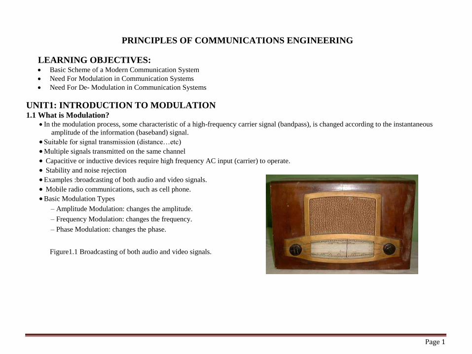
An example of the message signal m(t), the carrier c(t), and the modulated signal u (t). This figure shows that a relatively
slowly varying message signal m(t) is changed into a rapidly varying modulated signal u(t), and due to its rapid changes with
time, it contains higher frequency components.
Page 7
At the same time, the modulated signal retains the main characteristics of the message signal; therefore, it can be used to
retrieve the message signal at the receiver .
1.3.6 Double-Sideband Suppressed-Carrier AM An example of message, carrier, and DSB-SC modulated signals
Page 8
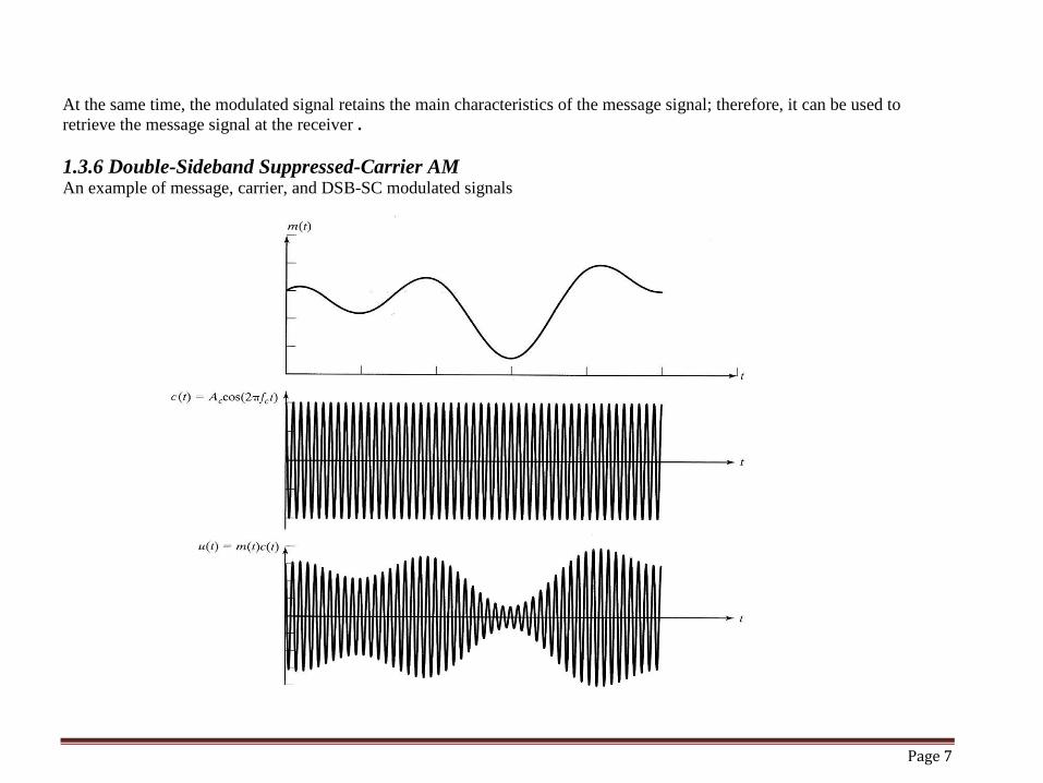
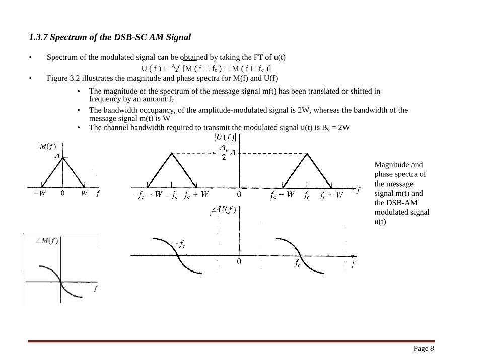
1.3.7 Spectrum of the DSB-SC AM Signal
• Spectrum of the modulated signal can be obtained by taking the FT of u(t)
U ( f ) A2c [M ( f fc ) M ( f fc )]
• Figure 3.2 illustrates the magnitude and phase spectra for M(f) and U(f)
• The magnitude of the spectrum of the message signal m(t) has been translated or shifted in frequency by an amount fc
• The bandwidth occupancy, of the amplitude-modulated signal is 2W, whereas the bandwidth of the message signal m(t) is W
• The channel bandwidth required to transmit the modulated signal u(t) is Bc = 2W
Magnitude and
phase spectra of
the message
signal m(t) and
the DSB-AM
modulated signal
u(t)

Page 9
Unit 2: FREQUENCY AND PHASE MODULATION (ANGLE MODULATION)
2.1ANGLE MODULATION : • When frequency or phase of the carrier is varied
by the modulating signal , then it is called angle modulation.
• Frequency Modulation – When the frequency of the carrier varies as per amplitude of modulating signal, then it is called
frequency modulation (FM).
• Phase Modulation - When the phase of the carrier varies as per amplitude of modulating signal, then it is called phase
modulation (PM).
• Amplitude of the modulated carrier remains constant in both modulation system

Page 10
Time domain representation

Page 11
2.2 Compare FM-PM : • The basic difference between FM & PM lies in which property of the carrier is directly varied by modulating signal.
• In FM, the frequency of carrier is varied directly.
• In PM, phase of the carrier is varied directly. Instantaneous phase deviation is represented by θ(t). • Instantaneous phase= ωct + θ(t) rad.
• Instantaneous frequency deviation = • d/dt {θ(t)} = θ’(t) Hz.
• The instantaneous frequency deviation is the instantaneous change in carrier frequency and is equal to the rate at which
instantaneous phase deviation takes place.
• Instantaneous frequency is defined as frequency of the carrier at a given instant of time and is given as
ωi(t) =d/dt [ωc.t + θ(t)] = ωc + θ’(t) rad/sec.
• Instantaneous phase deviation θ (t) is proportional to modulating signal voltage,
θ (t) = k em(t) rad. ( k is deviation sensitivity of phase.).
• Instantaneous frequency deviation θ’ (t) is proportional to modulating signal voltage,
θ’ (t) = k1 em(t) rad. ( k1 is deviation sensitivity of frequency.)

Page 12
Frequency modulation

Page 13
2.3 Observations from the FM & PM waveforms –
1. Both FM & PM waveforms are identical except the phase shift.
2. For FM, the maximum frequency deviation takes place when modulating signal is at +ve and –ve peaks.
3. For PM, the maximum frequency deviation takes place near zero crossing of the modulating signal.
4. It is diffcult to know from modulated waveform whether the modulation is FM or PM.
2.4Bandwidth Requirement – for FM-
The BW requirement can be obtained depending on the modulation index (M.I).
The M.I. can be classified as high(more than 10), medium (1 to 10) and low (less than 1).
The low index systems are called narrowband FM in which frequency spectrum resembles AM. BW (fm) =2fm Hz. For high index modulation, BW = 2*δ.(Freq. dev.) BW can also be found out by Bessel table-
BWfm = 2.n.fm where n is the number of sidebands obtained from table.
2.5Carson’s Rule – Rule gives approximate minimum BW of angle modulated signal as
BW fm = 2{δ + fm(max)} Hz.
From the above equation, it is found that the BW accommodates almost 98% of the total transmitted power

Page 14
2.6 Advantages of Angle Modulation over AM- • 1. As the amplitude of FM carrier is constant, the noise interference is minimum.
• 2. The amplitude of FM carrier is constant and is independent of depth of modulation. Hence transmitter power remains
constant in FM whereas it varies in AM.
• 3. As against the limitation of depth of modulation in AM, in FM depth of modulation can be increased to any value, without
causing any distortion.
• Disadvantages of FM compared to AM-
• 1. BW requirement of FM is very high as compared to AM.
• 2. FM equipments are more complex and hence costly.
• Area covered by FM is limited, to line of sight area but AM coverage area is large.
2.7 Comparison between FM and AM -
Parameter AM FM
Origin AM method of audio FM radio was developed in the
transmission was first United states mainly by Edwin
successfully carried out in the Armstrong in the 1930s.
mid 1870s.
Modulating In AM, a radio wave known as In FM, a radio wave known as the
differences the "carrier" or "carrier wave" "carrier" or "carrier wave" is

Page 15
is modulated in amplitude by modulated in frequency by the
the signal that is to be signal that is to be transmitted.
transmitted
It is used in both analog and It is used in both analog and digital
Importance digital communication and communication and telemetry
telemetry
Frequency AM radio ranges from 535 to FM radio ranges in a higher
Range 1705 KHz (OR) Up to 1200 Bits spectrum from 88 to 108 MHz. (OR)
per second. 1200 to 2400 bits per second.

Page 16
2.8Comparison between FM and AM –
Parameter AM FM
Bandwidth Twice the highest modulating Twice the sum of the modulating
Requirements
frequency. In AM radio broadcasting, signal frequency and the frequency
the modulating signal has bandwidth deviation. If the frequency deviation is
of 15kHz, and hence the bandwidth of 75kHz and the modulating signal
an amplitude-modulated signal is frequency is 15kHz, the bandwidth
30kHz. required is 180kHz.
Complexity Transmitter and receiver are simple Transmitter and receiver are more
but synchronization is needed in case complex as variation of modulating
of SSBSC AM carrier. signal has to be converted and
detected from corresponding variation
in frequencies.(i.e. voltage to
frequency and frequency to voltage
conversion has to be done).
Noise AM is more susceptible to noise FM is less susceptible to noise because
because noise affects amplitude, information in an FM signal is
which is where information is transmitted through varying the
"stored" in an AM signal. frequency, and not the amplitude.

Page 17

Page 18
2.8 Comparison between FM and PM -
Sr No. FM PM
1 The max frequency deviation The max phase deviation depends
depends on amplitude of on amplitude of modulating signal
modulating signal and its frequency
2 Frequency of the carrier is Phase of the carrier is modulated
modulated by modulating signal. by modulating signal.
3 Modulation index is increased as Modulation index remains same if
modulation frequency is reduced modulating signal frequency is
and vice versa. change.

Page 19
2.9 Modulators Carrier frequency can be generated by LC oscillator.
By varying the values of L or C of tank circuit, carrier frequency can be changed.
Properties of BJT,FET and varactor diodes can be varied by changing the voltage across them.
When these components are used with LC tank circuits, we are able to vary frequency of oscillator by changing the reactance of
L or C.
2.10TWO types of FM Modulators – Indirect FM – Modulation is obtained by phase modulation of the carrier.
An instantaneous phase of the carrier is directly proportional to the amplitude of the modulating signal.
Direct FM- The frequency of carrier is varied directly by modulating signal.
An instantaneous frequency variation is directly proportional to the amplitude of the modulating signal.
2.11FET Reactance Modulator –
There are a number of devices whose reactance can be varied by the application of voltage. These include FET and BJT, varactor diode etc.
If such a device is placed across the tank circuit of the L-C oscillator, then FM will be produced when the reactance of the device is varied by the modulating voltage.
At the carrier frequency, the oscillator inductance is tuned by its own capacitance in parallel with the average reactance to the variable reactance device.
2.12Advantages of FET Reactance Modulator –
Due to FET characteristics, linear relationship between modulating voltage and transconductance can be achieved.
This method produces enough frequency deviation and hence no frequency multiplication is required.
Disadvantages - Frequency stability is poor as lumped components are used.
Use – This method is used for low modulation index application.

Page 20
UNIT 3: PRE EMPHASIS AND DE-EMPHASIS
3.1Pre-emphasis:Pre-emphasis refers to boosting the relative amplitudes of the modulating voltage for higher audio
frequencies from 2 to approximately 15 KHz.
3.2 De-emphasis:De-emphasis means attenuating those frequencies by the amount by which they are boosted.

Page 21

Page 22
3.3 The combined effect of pre-emphasis and de-emphasis is to increase high frequency components
during transmission so that they will be stronger and not masked by noise.

Page 23
Phase Modulation (PM)

Page 24
UNIT4: Digital modulation
4.1Three basic methods Amplitude shift keying (ASK)
Frequency shift keying (FSK)
Phase shift keying (PSK
4.2Amplitude shift keying (ASK) Use different amplitude to represent 0 and 1. Simple, low bandwidth – Sensitive to interference. Multi-path propagation, noise or path loss heavily influence the amplitude. A constant amplitude in wireless environment can not be guaranteed. Used in wired optical communication. A light pulse =1, no light =0.

Page 25
4.3 Frequency shift keying (FSK) • Binary FSK (BFSK) – One frequency for 0 and one • frequency for 1. – needs larger bandwidth • • Avoid discontinuity – Discontinuity creates high • frequencies as side effects. – Continuous phase modulation (CPM) can be used. • • Demodulation: – Use two bandpass filters for 2 frequencies.
4.4 Phase shift keying (PSK) • Use shift in phase to represent data. • • Binary PSK (BPSK) – Shift the phase by 180. • • Synchronization is important • • More resistant to interference • • More complex transmitters and receivers.

Page 26
UNIT5:ANALOG-TO-DIGITAL CONVERSION
5.1 INTRODUCTION A digital signal is superior to an analog signal because it is more robust to noise and can easily be recovered,
corrected and amplified. For this reason, the tendency today is to change an analog signal to digital data. In this
section we describe two techniques, pulse code modulation and delta modulation.
5.2 PCM PCM consists of three steps to digitize an analog signal:
1. Sampling 2. Quantization 3. Binary encoding
Before we sample, we have to filter the signal to limit the maximum frequency of the signal as it affects the sampling rate.
Filtering should ensure that we do not distort the signal, ie remove high frequency components that affect the signal shape.

Page 27
5.3Components of PCM encoder

Page 28
5.3 Sampling Analog signal is sampled every TS secs. Ts is referred to as the sampling interval. fs = 1/Ts is called the sampling rate or sampling frequency.
5.3.1 There are 3 sampling methods: Ideal - an impulse at each sampling instant
Natural - a pulse of short width with varying amplitude
Flattop - sample and hold, like natural but with single amplitude value The process is referred to as pulse amplitude modulation PAM and the outcome is a signal with analog (non integer) values
Three different sampling methods for PCM

Page 29
5.4 Quantization: Sampling results in a series of pulses of varying amplitude values ranging between two limits: a min and a max. The amplitude values are infinite between the two limits.We need to map the infinite amplitude values onto a finite set of known values.This is achieved by dividing the distance between min and max into L zones, each of height . (max - min)/L
5.5Quantization Error When a signal is quantized, we introduce an error - the coded signal is an approximation of the actual amplitude value. The difference between actual and coded value (midpoint) is referred to as the quantization error. The more zones, the smaller which results in smaller errors. BUT, the more zones the more bits required to encode the samples -> higher bit rate
5.6 Bit rate and bandwidth requirements of PCM The bit rate of a PCM signal can be calculated form the number of bits per sample x the sampling rate Bit rate = nb x fs The bandwidth required to transmit this signal depends on the type of line encoding used. Refer to previous section for discussion and formulas. A digitized signal will always need more bandwidth than the original analog signal. Price we pay for robustness and other features of digital transmission.
5.7 PCM Decoder • To recover an analog signal from a digitized signal we follow the following steps:
– We use a hold circuit that holds the amplitude value of a pulse till the next pulse arrives.
– We pass this signal through a low pass filter with a cutoff frequency that is equal to the highest frequency in the pre-sampled signal.
• The higher the value of L, the less distorted a signal is recovered.

Page 30

Page 31
5.8 Delta Modulation • This scheme sends only the difference between pulses, if the pulse at time tn+1 is higher in amplitude value than the pulse at
time tn, then a single bit, say a “1”, is used to indicate the positive value. • If the pulse is lower in value, resulting in a negative value, a “0” is used. • This scheme works well for small changes in signal values between samples. • If changes in amplitude are large, this will result in large errors. 5.9 Delta PCM (DPCM) • Instead of using one bit to indicate positive and negative differences, we can use more bits -> quantization of the difference. • Each bit code is used to represent the value of the difference. • The more bits the more levels -> the higher the accuracy.
Multiple choice questions.
Q.1As compared to sound waves frequency of radio waves is
A. lower
B. higher
C. equal
D. may be higher or lower

Page 32
Q.2 At end of communication system, signal is converted from radio to
A. sound
B. mechanical energy
C. kinetic energy
D. potential energy
Q.3Decrease in strength of signal is known as
A. tuning
B. modulation
C. attenuation
D. amplification
Q.4If frequency of modulated wave is less than frequency of carrier wave, then input signal is
A. negative
B. positive
C. zero
D. infinite
Page 33
Short questions and answers:
Q.1. Compare Wideband & Narrow band FM.
Q.2. Compare FM and AM.
Q.3. Advantages of FM over AM.
Q.4. Explain square law modulator.
Q.5. What are the various types of pulse modulation & and also draw the waveform.
Q.6. What is total power transmitted in AM ?
Q.7. Explain the frequency spectrum of FM.
Q.8Write a short note on Envelope detector.
Q.9. Short note on Varactor Diode Modulator.
Long questions and answers:
Q.1. Compare TDM & FDM.
Q.2. Compare PAM, PWM & PPM.
Q.3.Explain Ring Modulator.
Q.4. Explain the working of Armstrong frequency modulation system.

Page 34