Principles of 3G (CDMA), 4G (OFDMA) and 5G Part-A · PDF filePrinciples of 3G (CDMA), 4G...
50
Principles of 3G (CDMA), 4G (OFDMA) and 5G Part-A Professor A. Manikas Imperial College London EE303 Prof. A. Manikas (Imperial College) EE303: 3G, 4G and 5G (Part A) v16 1 / 50
Transcript of Principles of 3G (CDMA), 4G (OFDMA) and 5G Part-A · PDF filePrinciples of 3G (CDMA), 4G...

Principles of3G (CDMA), 4G (OFDMA) and 5G
Part-A
Professor A. Manikas
Imperial College London
EE303
Prof. A. Manikas (Imperial College) EE303: 3G, 4G and 5G (Part A) v16 1 / 50

Table of Contents1 Introduction - 3G, 4G, 5G Mobile Cellular Systems
3GPPMobile EvolutionBasic Elements of Mobile Cellular SystemsFDD and TDDChannel Reuse and Reuse DistanceSignal Overlay
2 3G (CDMA)3G: Specifications3G: DS-QPSK implementation No.1 (QPSK1)3G: DS-QPSK implementation No.2 (QPSK2)3G: Channelisation Codes & Scrambling Codes3G: Base Station Tx3G: Handset TxSSS and CDMABasics of CDMABasic Properties of CDMA SystemsDS-CDMA: Synchronization
Analysis of a DS BPSK CDMA SystemModelling and AnalysisSNIRout as a function of EUE, Nc and KBER as a function of EUE, Nc and KBPSK Examples
Some Important CDMA System ComponentsPower ControlVoice Activity FactorSectorization
Prof. A. Manikas (Imperial College) EE303: 3G, 4G and 5G (Part A) v16 2 / 50

Introduction - 3G, 4G, 5G Mobile Cellular Systems 3GPP
Introduction - 3G, 4G, 5G Mobile Cellular SystemsThe 3GPP (3’d Generation Partnership Project )
I developed the 3G standarsI developed the 4G standardsI is developing standards towards next generation (5G)
3GPP expanded in 2011 to include 380 individual membercompanies and 5 Standards Development Organisations as shownbelow
Prof. A. Manikas (Imperial College) EE303: 3G, 4G and 5G (Part A) v16 3 / 50
Introduction - 3G, 4G, 5G Mobile Cellular Systems Mobile Evolution
Mobile Evolution - Motivation
Prof. A. Manikas (Imperial College) EE303: 3G, 4G and 5G (Part A) v16 4 / 50

Introduction - 3G, 4G, 5G Mobile Cellular Systems Mobile Evolution
Mobile Evolution - Motivation (cont.)
Prof. A. Manikas (Imperial College) EE303: 3G, 4G and 5G (Part A) v16 5 / 50

Introduction - 3G, 4G, 5G Mobile Cellular Systems Basic Elements of Mobile Cellular Systems
Basic Elements of Mobile Cellular Systems
A mobile cellular system consists ofI base stations ,I cells (a cell is the area serviced by a base station) andI mobiles (subscribers).
When a call originates, the base station negotiates with the mobile onvarious aspects (such as the channel used etc.), before establishingcommunications. After this, as the mobile moves from cell-to-cell, theservice is handed (hand-off or handover ) from one base station toanother.
Only one base station (BS) will service a mobile at any one time.
Note:I base station to mobile is known as FORWARD LINK (or Downlink)I mobile to base station is known as REVERSE LINK (or Uplink)
Prof. A. Manikas (Imperial College) EE303: 3G, 4G and 5G (Part A) v16 6 / 50

Introduction - 3G, 4G, 5G Mobile Cellular Systems Basic Elements of Mobile Cellular Systems
Type of channels:
Examples of uplink and downlink channels:
UPLINK DOWNLINKTraffi c Channel Traffi c ChannelAccess Channel Pilot Channel
Synchron.ChannelPaging Channel
Prof. A. Manikas (Imperial College) EE303: 3G, 4G and 5G (Part A) v16 7 / 50

Introduction - 3G, 4G, 5G Mobile Cellular Systems FDD and TDD
FDD and TDD
Based of the spectrum used in "uplink" and "downling", there aretwo systems
I FDD (Frequency Division Duplex), andI TDD (Time Division Duplex)I Definitions:
FDD: TDD:
Prof. A. Manikas (Imperial College) EE303: 3G, 4G and 5G (Part A) v16 8 / 50

Introduction - 3G, 4G, 5G Mobile Cellular Systems Channel Reuse and Reuse Distance
Channel Reuse and Reuse Distance
Most cellular systems use frequency division multiplex access (FDMA)and/or time division multiplex access (TDMA) technique to improvethe system capacity.
Example: 2G cellular systems = FDMA/TDMA
In these systems, each user is assigned one time/frequency-slot.I When the system gets larger,
time/frequency-slots 6= unique for each and every user
as this will limit the system capacity. Therefore these slots(time/frequency) have to be reused
I This implies that there is interference from other cells sharing thesame channels.
Prof. A. Manikas (Imperial College) EE303: 3G, 4G and 5G (Part A) v16 9 / 50

Introduction - 3G, 4G, 5G Mobile Cellular Systems Channel Reuse and Reuse Distance
Cluster= the number of cells which have unique time/freq-slots foreach and every user.
I Available cluster sizes: 1,3,4,7,9,12,. . .
cluster size=3 cluster size=7
I The reuse distance D, in these systems, is determined by the worstcase interference situation.
I D is defined as the distance between the centers of two co-channelcells.
D = R√3C (1)
where C = cluster size
R = cell radiusProf. A. Manikas (Imperial College) EE303: 3G, 4G and 5G (Part A) v16 10 / 50

Introduction - 3G, 4G, 5G Mobile Cellular Systems Channel Reuse and Reuse Distance
cluster size: 4 cluster size: 7
Prof. A. Manikas (Imperial College) EE303: 3G, 4G and 5G (Part A) v16 11 / 50
Introduction - 3G, 4G, 5G Mobile Cellular Systems Channel Reuse and Reuse Distance
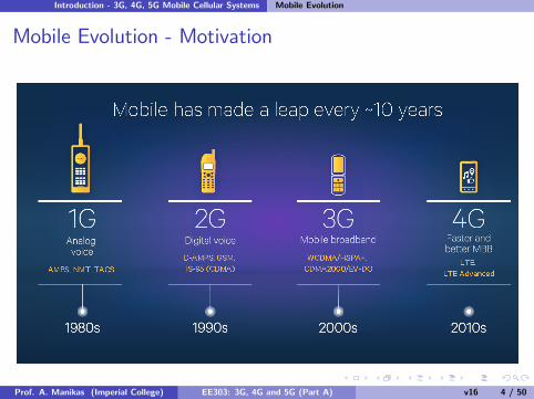
D is known as the reuse distance of the system.
Remember: The system capacity could be increased by increasingthe number of channels available in a single cell, i.e. reducing thereuse distance D.
But this reduction is limited by the co-channel interference, (i.e. theinterference from other cells sharing the same channels).
In a CDMA system , the available spectrum and time are not splitinto distinct slots. Instead the whole (available) spectrum is used byeach user.
I Since the same frequency channel could be used by all theusers/subscribers in a cell, the cluster size could be reduced to 1, i.e.
if CDMA then cluster = 1 cell and D = R√3 (2)
Prof. A. Manikas (Imperial College) EE303: 3G, 4G and 5G (Part A) v16 12 / 50

Introduction - 3G, 4G, 5G Mobile Cellular Systems Signal Overlay
Signal OverlayThe spread spectrum signal, from a CDMA system, has a very low powerspectral density and, therefore, a CDMA system can overlay on topof 2G narrow-band mobile cellular systems (of the same frequency band).This is because the interference (due to CDMA signals), added to anarrow-band mobile system channel, is very low and, therefore,the presence of CDMA signal will hardly affect the performance of thenarrow-band mobile system.The CDMA system, however, needs to perform some extra processingto reject the narrowband interference due to the presence of thenarrow-band signals.Comment:The capacity and performance of a mobile cellular system could besignificantly improved by using CDMA techniques. In the paper “On theCapacity of a Cellular CDMA”, IEEE Transactions on VehicularTechnology, Vol.40, 1991 (by Gilhousen et al) the improvement in thecapacity is discussed and it is stated that “no other proposed schemeappears to even approach this (CDMA) performance”.
Prof. A. Manikas (Imperial College) EE303: 3G, 4G and 5G (Part A) v16 13 / 50

3G (CDMA) 3G: Specifications
3G: Specifications
IS-95 UMTS
Generation 2G (USA) 3G (EU)
Type CDMA W-CDMA
Frame duration 20msec 10msec
Uplink
25MHz︷ ︸︸ ︷824− 849MHz︸ ︷︷ ︸
mod:QPSK
60MHz︷ ︸︸ ︷1920− 1980MHz︸ ︷︷ ︸
mod:balanced QPSK, i.e. QPSK2
Downlink
25MHz︷ ︸︸ ︷869− 894MHz︸ ︷︷ ︸
mod:oQPSK
60MHz︷ ︸︸ ︷2110− 2170MHz︸ ︷︷ ︸
mod:dual QPSK, i.e. QPSK1
Bss 1.23MHz 5MHz,10MHz,20MHz
Tc 813.8ns 244ns,122ns, 61ns
rc = 1Tc
1.2288Mchipssec 4.096Mchipssec (reduced to 3.084Mchipssec )
roll-off-factor 0.22;Note: Bss = 1Tc(1+roll-off-factor)=4.99712MHz'5MHz
Receiver’s type RAKE RAKE
Prof. A. Manikas (Imperial College) EE303: 3G, 4G and 5G (Part A) v16 14 / 50

3G (CDMA) 3G: DS-QPSK implementation No.1 (QPSK1)
3G: DS-QPSK implementation No.1 (QPSK1)
(Note: if =Tc2 delay is inserted then OQPSK1− offset QPSK1)
Transmitter:
m(t)S/P
m (t)I
m (t)Q
b (t)I
b (t)Q
h(t)
h(t)
P . (2 F t)s ccos π
P . (2 F t)s csin π
s (t)I
s (t)Q
s(t)
s(t) =√2Ps . cos
(2πFc t + tan−1
bQ (t).mQ (t)bI (t).mI (t)
)Prof. A. Manikas (Imperial College) EE303: 3G, 4G and 5G (Part A) v16 15 / 50

3G (CDMA) 3G: DS-QPSK implementation No.1 (QPSK1)
Receiver:
r(t)
2cos(2 F t)π c
2sin(2 F t)π c
b (t)I
(n )T1 cs
nTcs
h(t)
h(t) b (t)Q
P/S
(n )T1 cs
nTcs
Prof. A. Manikas (Imperial College) EE303: 3G, 4G and 5G (Part A) v16 16 / 50

3G (CDMA) 3G: DS-QPSK implementation No.2 (QPSK2)
3G: DS-QPSK implementation No.2 (QPSK2)
(Note: if =Tc2 delay is inserted then OQPSK2 )
Transmitter:
m(t) b (t)I
b (t)Q
h(t)
h(t)
P . (2 F t)s ccos π
P . (2 F t)s csin π
s (t)I
s (t)Q
s(t)
s(t) =√2Ps . cos
(2πFc t + tan−1
bQ (t).m(t)bI (t).m(t)
)
Prof. A. Manikas (Imperial College) EE303: 3G, 4G and 5G (Part A) v16 17 / 50

3G (CDMA) 3G: DS-QPSK implementation No.2 (QPSK2)
Receiver:
(n )T1 cs
nTcsr(t)
2cos(2 F t)π c
2sin(2 F t)π c
b (t)Ih(t)
h(t) b (t)Q
Prof. A. Manikas (Imperial College) EE303: 3G, 4G and 5G (Part A) v16 18 / 50

3G (CDMA) 3G: Channelisation Codes & Scrambling Codes
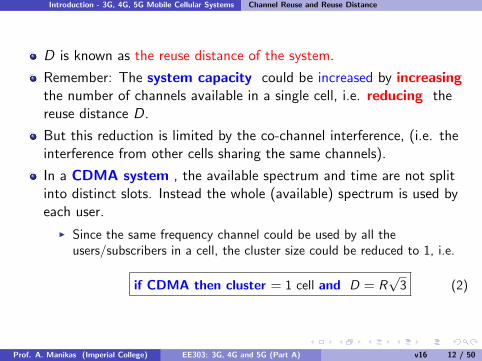
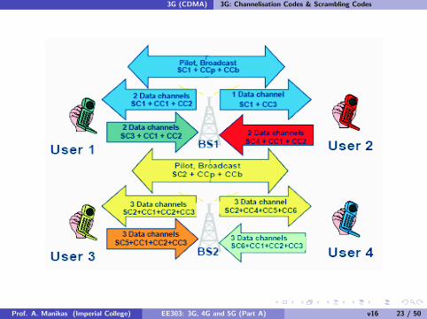
3G: Channelisation Codes & Scrambling Codes
In 3G WCDMA:I PN-codes = channelisation codes + scrambling codes
Channelisation codes :I are used to differentiate between users/channels within a cellI also known as OVSF (Orthogonal Variable Spreading Factor) codesI these are the Walsh codes (see next page)
Scambling codes:I to differentiate between cellsI these are m-sequence or gold-codes
Prof. A. Manikas (Imperial College) EE303: 3G, 4G and 5G (Part A) v16 19 / 50

3G (CDMA) 3G: Channelisation Codes & Scrambling Codes
IS95 - Walsh Function of order-64
Prof. A. Manikas (Imperial College) EE303: 3G, 4G and 5G (Part A) v16 20 / 50

3G (CDMA) 3G: Channelisation Codes & Scrambling Codes
Prof. A. Manikas (Imperial College) EE303: 3G, 4G and 5G (Part A) v16 21 / 50
3G (CDMA) 3G: Channelisation Codes & Scrambling Codes
Prof. A. Manikas (Imperial College) EE303: 3G, 4G and 5G (Part A) v16 22 / 50
3G (CDMA) 3G: Channelisation Codes & Scrambling Codes
Prof. A. Manikas (Imperial College) EE303: 3G, 4G and 5G (Part A) v16 23 / 50

3G (CDMA) 3G: Base Station Tx
3G: Base Station Tx
Prof. A. Manikas (Imperial College) EE303: 3G, 4G and 5G (Part A) v16 24 / 50

3G (CDMA) 3G: Handset Tx
3G: Handset Tx
Prof. A. Manikas (Imperial College) EE303: 3G, 4G and 5G (Part A) v16 25 / 50

3G (CDMA) SSS and CDMA
(a) SSS: (b) CDMA (K users):
Prof. A. Manikas (Imperial College) EE303: 3G, 4G and 5G (Part A) v16 26 / 50

3G (CDMA) SSS and CDMA
The PN signal b(t) is a function of a PN sequence of ±1’s {α[n]}
I The sequences {α[n]} must agreed upon in advance by Tx and Rx andthey have status of password.
I This implies that :F knowledge of {α[n]}⇒demodulation=possibleF without knowledge of {α[n]}⇒demod.=very diffi cult
I If {α[n]} (i.e. “password”) is purely random, with no mathematicalstructure, then
F without knowledge of {α[n]}⇒demodulation=impossible
I However all practical random sequences have some periodic structure.This means:
α[n] = α[n+Nc ] (3)
where Nc =period of sequencei.e. pseudo-random sequence (PN-sequence)
Prof. A. Manikas (Imperial College) EE303: 3G, 4G and 5G (Part A) v16 27 / 50

3G (CDMA) SSS and CDMA
Remember
DS-SSS (Examples: DS-BPSK, DS-QPSK):
b(t) = ∑n
α[n].c(t − nTc ) (4)
where {α[n]} is a sequence of ±1’s;c(t) is an energy signal of duration Tc
FH-SSS (Examples: FH-FSK)
b(t) = ∑nexp {j(2πk[n]F1t + φ[n])} .c(t − nTc ) (5)
where {k[n]} is a sequence of integers such that
{α[n]} 7→ {k[n]} (6)
and {α[n]} is a sequence of ±1’s;c(t) is an energy signal of duration Tc
Prof. A. Manikas (Imperial College) EE303: 3G, 4G and 5G (Part A) v16 28 / 50

3G (CDMA) Basics of CDMA
Basics of CDMABLOCK DIAGRAM
Prof. A. Manikas (Imperial College) EE303: 3G, 4G and 5G (Part A) v16 29 / 50
3G (CDMA) Basics of CDMA
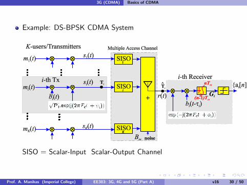
Example: DS-BPSK CDMA System
SISO = Scalar-Input Scalar-Output Channel
Prof. A. Manikas (Imperial College) EE303: 3G, 4G and 5G (Part A) v16 30 / 50

3G (CDMA) Basics of CDMA
SISO Multipath Channel
SISO Multipath channel of the i-th user
In the absence of multipaths the above diagram has only τi1 and βi1terms.
For the simplicity we will drop the second subscript and we will use τiand βi ,and thus the BPSK/DS-CDMA in the absence of multipathsmay be represented as follows:↘
Prof. A. Manikas (Imperial College) EE303: 3G, 4G and 5G (Part A) v16 31 / 50

3G (CDMA) Basics of CDMA
Prof. A. Manikas (Imperial College) EE303: 3G, 4G and 5G (Part A) v16 32 / 50

3G (CDMA) Basics of CDMA
Basic Properties of CDMA Systems
CDMA is one of the applications of spread spectrum communicationswhich is used in civilian, commercial and military communication.
Two systems: DS-CDMA (i.e averaging system) and FH-CDMA (i.e.avoidance system).In this course only DS-CDMA will be considered.
Assign a specific PN-code to each user
PN-code (having the status of ‘password’) acts like a ‘channel’
DS-CDMA: two main casesI PN-signal period = NcTc = Tcs (known as ‘short codes ’CDMA)I PN-signal period = NcTc � Tcs (known as ‘long codes ’CDMA)
Prof. A. Manikas (Imperial College) EE303: 3G, 4G and 5G (Part A) v16 33 / 50

3G (CDMA) Basics of CDMA
DS-CDMA: two main types1 synchronous DS-CDMA
i-th user
j-th user2 non-synchronous DS-CDMA
i-th user
j-th user
Prof. A. Manikas (Imperial College) EE303: 3G, 4G and 5G (Part A) v16 34 / 50

3G (CDMA) Basics of CDMA
DS-CDMA: SynchronizationThe Rx requires a replica of the PN code, with the correct clockphase, in order to despread the signal.Therefore, Rx =“synchronization circuits”+ “demod. circuits”The process of synchronizing the receiver to the transmitter’s PNcode consists of two stages:
I Acquisition (coarse synchronization).I Tracking (fine synchronization).
Operation: acquisition ; tracking + demodulation; loose tracking ;acquisition ; tracking+demodulation; ......etc..........
Prof. A. Manikas (Imperial College) EE303: 3G, 4G and 5G (Part A) v16 35 / 50

3G (CDMA) Analysis of a DS BPSK CDMA System
Analysis of a DS BPSK CDMA Systemobjective: to relate the BER pe with the total number of users K aswell as with the EUEequ at the receiver.i.e.
pe = f{EUEequ,K} (7)
Main AssumptionsI single cell system of K users,I @ multipathsI PN code period = Nc =PG=TcsTcI System=perfectly power-controlled(all SS signals arrive at the receiver with the same power)
F NB: power control can often be implemented in practice with greataccuracy.
I System = totally asynchronous (there is no common timing referencefor the transmitters/users)
F NB: This is actually an advantage of CDMA over other multiple accesstechniques, because all users can transmit independently and nosignalling information is required.
Prof. A. Manikas (Imperial College) EE303: 3G, 4G and 5G (Part A) v16 36 / 50

3G (CDMA) Analysis of a DS BPSK CDMA System
DS/BPSK CDMA System: Modelling and Analysis
Note that the carrier of i th transmitter is√Pi . exp (j(2πFc t + ψi ))
Prof. A. Manikas (Imperial College) EE303: 3G, 4G and 5G (Part A) v16 37 / 50
3G (CDMA) Analysis of a DS BPSK CDMA System
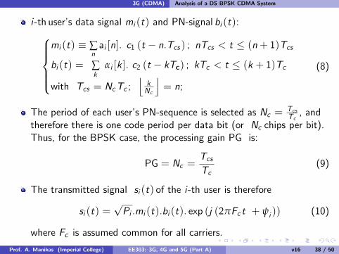
i-th user’s data signal mi (t) and PN-signal bi (t):mi (t) ≡ ∑
nai [n]. c1 (t − n.Tcs ) ; nTcs < t ≤ (n+ 1)Tcs
bi (t) = ∑k
αi [k ]. c2 (t − kTc) ; kTc < t ≤ (k + 1)Tc
with Tcs = NcTc ;⌊kNc
⌋= n;
(8)
The period of each user’s PN-sequence is selected as Nc = TcsTc, and
therefore there is one code period per data bit (or Nc chips per bit).Thus, for the BPSK case, the processing gain PG is:
PG = Nc =TcsTc
(9)
The transmitted signal si (t) of the i-th user is therefore
si (t) =√Pi .mi (t).bi (t). exp (j (2πFc t + ψi )) (10)
where Fc is assumed common for all carriers.
Prof. A. Manikas (Imperial College) EE303: 3G, 4G and 5G (Part A) v16 38 / 50
3G (CDMA) Analysis of a DS BPSK CDMA System
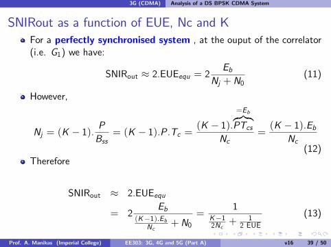
SNIRout as a function of EUE, Nc and KFor a perfectly synchronised system , at the ouput of the correlator(i.e. G1) we have:
SNIRout ≈ 2.EUEequ = 2Eb
Nj +N0(11)
However,
Nj = (K − 1).PBss
= (K − 1).P.Tc =(K − 1).
=Eb︷︸︸︷PTcs
Nc=(K − 1).Eb
Nc(12)
Therefore
SNIRout ≈ 2.EUEequ
= 2Eb
(K−1).EbNc
+N0=
1K−12Nc
+ 12 EUE
(13)
Prof. A. Manikas (Imperial College) EE303: 3G, 4G and 5G (Part A) v16 39 / 50

3G (CDMA) Analysis of a DS BPSK CDMA System
BER as a function of EUE, Nc and K
We have seen that
SNIRout ≈{K − 12Nc
+1
2 EUE
}−1(14)
However,
pe =T{√SNIRout
}(15)
which implies that
pe = T{√
2EUEequ}= T
1√K−12Nc
+ 12 EUE
(16)
Prof. A. Manikas (Imperial College) EE303: 3G, 4G and 5G (Part A) v16 40 / 50

3G (CDMA) Analysis of a DS BPSK CDMA System
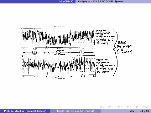
BPSK Examples
Prof. A. Manikas (Imperial College) EE303: 3G, 4G and 5G (Part A) v16 41 / 50

3G (CDMA) Analysis of a DS BPSK CDMA System
Prof. A. Manikas (Imperial College) EE303: 3G, 4G and 5G (Part A) v16 42 / 50
3G (CDMA) Analysis of a DS BPSK CDMA System
Prof. A. Manikas (Imperial College) EE303: 3G, 4G and 5G (Part A) v16 43 / 50
3G (CDMA) Some Important CDMA System Components
Power Control
In order to achieve the full benefits of using CDMA, the transmittedsignal powers Psi should be controlled in such a way that receivedsignal power, from all the users at a cell, are the same.This makes power control a key feature of CDMA mobile systems.
Prof. A. Manikas (Imperial College) EE303: 3G, 4G and 5G (Part A) v16 44 / 50

3G (CDMA) Some Important CDMA System Components
Voice Activity Factor
Human speech contains a lot of pauses where there is no data totransmit.Thus a speaker is active for about half the time due to listening andpauses in speech.
The fraction of time that a speaker is active is known asthe voice activity factor aExtensive studies have shown that 0.35 < a < 0.5.A popular value used is a = 3/8 = 0.375The voice activity feature can be taken into account in acommunication system by suppressing the transmission when voice isabsent.Assuming that we have a scheme where the carrier is turned-offduring the speech idle periods then a reduction in interference (bya factor of the voice activity) can be achieved.
Prof. A. Manikas (Imperial College) EE303: 3G, 4G and 5G (Part A) v16 45 / 50

3G (CDMA) Some Important CDMA System Components
implementation of voice activity:
{TDMA/FDMA: very diffi cult
CDMA: very easy
For a large number of users the capacity increases by a factor 1/a.Therefore, using the voice activity monitoring approach the capacityand the performance of a CDMA system will be improved(this improvement cannot be obtained in FDMA/TDMA systems)
In particular the power of a user’s signal at a specific time instant canbe expressed 1× Puser with probability a and 0× Puser withprobability (1− a).Using voice activity the performance can be improved even more.
BPSK : SNIRout = 2.EUEequ = 2Eb
Nj +N0(17)
where Nj =(K − 1).Ps .a
Bss(18)
Prof. A. Manikas (Imperial College) EE303: 3G, 4G and 5G (Part A) v16 46 / 50
3G (CDMA) Some Important CDMA System Components
Therefore we can model the “on-off”activity of each user a binomialdistribution, which implies that the probability that k user (out of K )are active is given as follows:
Pr(k users are active) =(kK
)ak (1− a)K−k (19)
where K is the number of users per cell
Note that as K =↑⇒spread of distribution=↓Set a threshold Kth , εth such that:
Pr(number of active users > Kth) < εth (20)
Prof. A. Manikas (Imperial College) EE303: 3G, 4G and 5G (Part A) v16 47 / 50

3G (CDMA) Some Important CDMA System Components
Sectorization
It is used in TDMA/FDMA and CDMA systems
Prof. A. Manikas (Imperial College) EE303: 3G, 4G and 5G (Part A) v16 48 / 50

3G (CDMA) Some Important CDMA System Components
Sectorization
Sectorization is achieved by using directional antennas instead ofomnidirectional antennas.
Each cell is divided to three sectors using three directionalantennas each having 120◦ beamwidth.Using sectorization the performance can be improved even more.(The expected value of the total interference is reduced by a factor ofs = 3wrt single omnidirectional antenna case)
BPSK : SNIRout = 2.EUEequ = 2Eb
Nj +N0(21)
where Nj =(K − 1).Ps .s
Bss(22)
In practice: 3 dB<SNIRout < 15dB
Prof. A. Manikas (Imperial College) EE303: 3G, 4G and 5G (Part A) v16 49 / 50

3G (CDMA) Some Important CDMA System Components
A better approach is to use three linear antenna arrays (smartantennas)
antenna array switched beam array system adaptive array system
Prof. A. Manikas (Imperial College) EE303: 3G, 4G and 5G (Part A) v16 50 / 50