PRIMERGY BX922 S2 Server Blade -...
106
PRIMERGY BX922 S2 Server Blade Operating Manual Edition February 2010
Transcript of PRIMERGY BX922 S2 Server Blade -...

PRIMERGY BX922 S2Server Blade Operating Manual
Edition February 2010

Comments… Suggestions… Corrections…The User Documentation Department would like toknow your opinion of this manual. Your feedback helpsus optimize our documentation to suit your individual needs.
Feel free to send us your comments by e-mail to email: [email protected].
Certified documentation according to DIN EN ISO 9001:2000To ensure a consistently high quality standard anduser-friendliness, this documentation was created tomeet the regulations of a quality management system which complies with the requirements of the standardDIN EN ISO 9001:2000.
cognitas. Gesellschaft für Technik-Dokumentation mbHwww.cognitas.de
Copyright and Trademarks
© c
ogni
tas.
Ges
ells
chft
für
Tech
nik-
Dok
ume
ntat
ion
mb
H 2
010
P
fad:
C:\P
rogr
am
me\
FC
T\ti
m_a
pp\ti
m_l
oca
l\wor
k\W
ALT
ER
\OB
J_D
OK
U-4
956-
001
.fm
Copyright © 2010 Fujitsu Technology Solutions GmbH.
All rights reserved.
Delivery subject to availability; right of technical modifications reserved.
All hardware and software names used are trade names and/or trademarks of their respective manufacturers.

BX922 S2 Operating Manual
Before reading this manual
For your safety
This manual contains important information for safely and correctly using this product.
Carefully read the manual before using this product. Pay particular attention to the accompanying manual "Safety notes and other important information" and ensure these safety notes are understood before using the product.
Keep this manual and the manual "Safety notes and other important information" in a safe place for easy reference while using this product.
Radio interference
This product is a "Class A" ITE (Information Technology Equipment) as defined by the Voluntary Control Council for Interference by Information Technology Equipment (VCCI) of Japan. In a domestic environment this product may cause radio interference, in which case the user may be required to take appropriate measures.
Aluminum electrolytic capacitors
The aluminum electrolytic capacitors used in the product's printed circuit board assemblies and in the mouse and keyboard are limited-life components. Use of these components beyond their operating life may result in electrolyte leakage or depletion, potentially causing emission of foul odor or smoke.
As a guideline, in a normal office environment (25°C) operating life is not expected to be reached within the maintenance support period (5 years). However, operating life may be reached more quickly if, for example, the product is used in a hot environment. The customer shall bear the cost of replacing replaceable components which have exceeded their operating life. Note that these are only guidelines, and do not constitute a guarantee of trouble-free operation during the maintenance support period.
High safety use
This product has been designed and manufactured for general uses such as general office use, personal use, domestic use and normal industrial use. It has not been designed or manufactured for uses which demand an extremely high level of safety and carry a direct and serious risk to life or body if such safety cannot be ensured.

Operating Manual BX922 S2
© c
ogni
tas.
Ges
ells
chft
für
Tech
nik-
Dok
ume
ntat
ion
mb
H 2
010
P
fad:
C:\P
rogr
am
me\
FC
T\ti
m_a
pp\ti
m_l
oca
l\wor
k\W
ALT
ER
\OB
J_D
OK
U-4
956-
001
.fm
These uses include control of nuclear reactions in nuclear power plants, automatic airplane flight control, air traffic control, traffic control in mass transport systems, medical devices for life support, and missile guidance control in weapons systems (hereafter, "high safety use"). Customers should not use this product for high safety use unless measures are in place for ensuring the level of safety demanded of such use. Please consult the sales staff of Fujitsu if intending to use this product for high safety use.
Measures against momentary voltage drop
This product may be affected by a momentary voltage drop in the power supply caused by lightning. To prevent a momentary voltage drop, use of an AC uninterruptible power supply is recommended.
(This notice follows the guidelines of Voltage Dip Immunity of Personal Computer issued by JEITA, the Japan Electronics and Information Technology Industries Association.)
Technology controlled by the Foreign Exchange and Foreign Trade Control Law of Japan
Documents produced by FUJITSU may contain technology controlled by the Foreign Exchange and Foreign Trade Control Law of Japan. Documents which contain such technology should not be exported from Japan or transferred to non-residents of Japan without first obtaining authorization in accordance with the above law.
Harmonic Current Standards
This product conforms to harmonic current standard JIS C 61000-3-2.
Only for the Japanese market:About SATA hard disk drives
The SATA version of this server supports hard disk drives with SATA / BC-SATA storage interfaces. Please note that the usage and operation conditions differ depending on the type of hard disk drive used.
Please refer to the following internet address for further information on the usage and operation conditions of each available type of hard disk drive:
http://primeserver.fujitsu.com/primergy/harddisk/

BX922 S2 Operating Manual
Only for the Japanese market:
I Although described in this manual, some sections do not apply to the Japanese market. These options and routines include:
– USB Flash Module (UFM)
– CSS (Customer Self Service)
– Conversion of standard power supply to hot-plug power supply
– DVD-RW drives
– Replacing the lithium battery
– 3rd party racks

Operating Manual BX922 S2
© c
ogni
tas.
Ges
ells
chft
für
Tech
nik-
Dok
ume
ntat
ion
mb
H 2
010
P
fad:
C:\P
rogr
am
me\
FC
T\ti
m_a
pp\ti
m_l
oca
l\wor
k\W
ALT
ER
\OB
J_D
OK
U-4
956-
001
.fm

BX922 S2 Operating Manual
Contents
1 Introduction . . . . . . . . . . . . . . . . . . . . . . . . . . . 11
1.1 Concept and target groups for this manual . . . . . . . . . 11
1.2 Documentation overview . . . . . . . . . . . . . . . . . . . 12
1.3 Performance features . . . . . . . . . . . . . . . . . . . . . 13
1.4 Notational conventions . . . . . . . . . . . . . . . . . . . . 19
1.5 Technical data . . . . . . . . . . . . . . . . . . . . . . . . . 20
2 Overview: Installation steps . . . . . . . . . . . . . . . . . . 23
3 Important notes . . . . . . . . . . . . . . . . . . . . . . . . . 25
3.1 Safety instructions . . . . . . . . . . . . . . . . . . . . . . . 25
3.2 CE conformity . . . . . . . . . . . . . . . . . . . . . . . . . 31
3.3 FCC class A device . . . . . . . . . . . . . . . . . . . . . . . 32
3.4 Transporting the Server Blade . . . . . . . . . . . . . . . . 32
3.5 Notes on installation in the system unit . . . . . . . . . . . 32
3.6 Environmental protection . . . . . . . . . . . . . . . . . . . 33
4 Installing the hardware . . . . . . . . . . . . . . . . . . . . . 35
4.1 Unpacking the server . . . . . . . . . . . . . . . . . . . . . 36
4.2 Installing the Server Blade in the system unit . . . . . . . . 36
4.3 Connecting devices . . . . . . . . . . . . . . . . . . . . . . 40
4.4 Instructions for connecting/disconnecting cables . . . . . . 41
5 Installation and operation . . . . . . . . . . . . . . . . . . . 43
5.1 Control and display elements . . . . . . . . . . . . . . . . . 43
Operating Manual BX922 S2
Contents
© c
ogni
tas.
Ges
ells
chft
für
Tech
nik-
Dok
ume
ntat
ion
mb
H 2
010
P
fad:
C:\P
rogr
am
me\
FC
T\ti
m_a
pp\ti
m_l
oca
l\wor
k\W
ALT
ER
\OB
J_D
OK
U-4
957-
001
.fm
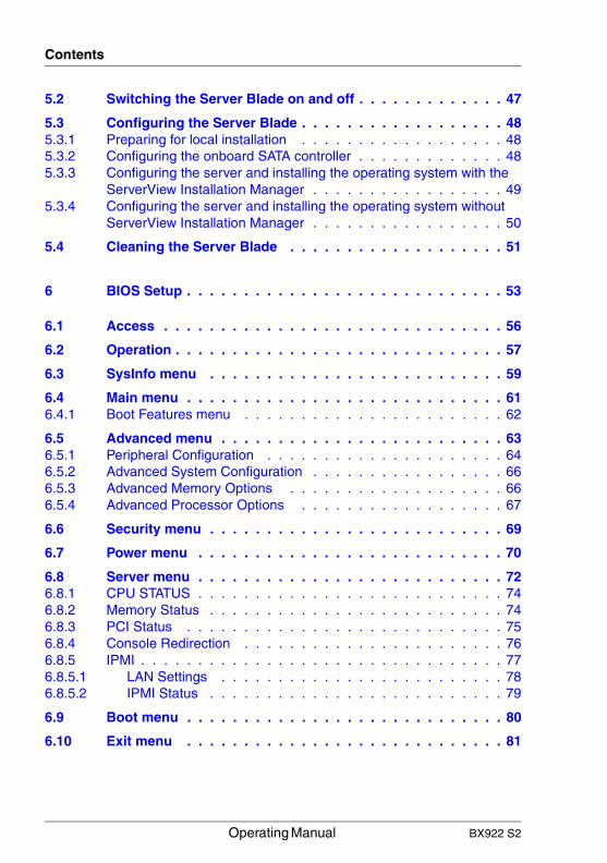
5.2 Switching the Server Blade on and off . . . . . . . . . . . . . 47
5.3 Configuring the Server Blade . . . . . . . . . . . . . . . . . . 485.3.1 Preparing for local installation . . . . . . . . . . . . . . . . . . 485.3.2 Configuring the onboard SATA controller . . . . . . . . . . . . . 485.3.3 Configuring the server and installing the operating system with the
ServerView Installation Manager . . . . . . . . . . . . . . . . . 495.3.4 Configuring the server and installing the operating system without
ServerView Installation Manager . . . . . . . . . . . . . . . . . 50
5.4 Cleaning the Server Blade . . . . . . . . . . . . . . . . . . . 51
6 BIOS Setup . . . . . . . . . . . . . . . . . . . . . . . . . . . . 53
6.1 Access . . . . . . . . . . . . . . . . . . . . . . . . . . . . . . 56
6.2 Operation . . . . . . . . . . . . . . . . . . . . . . . . . . . . . 57
6.3 SysInfo menu . . . . . . . . . . . . . . . . . . . . . . . . . . 59
6.4 Main menu . . . . . . . . . . . . . . . . . . . . . . . . . . . . 616.4.1 Boot Features menu . . . . . . . . . . . . . . . . . . . . . . . 62
6.5 Advanced menu . . . . . . . . . . . . . . . . . . . . . . . . . 636.5.1 Peripheral Configuration . . . . . . . . . . . . . . . . . . . . . 646.5.2 Advanced System Configuration . . . . . . . . . . . . . . . . . 666.5.3 Advanced Memory Options . . . . . . . . . . . . . . . . . . . 666.5.4 Advanced Processor Options . . . . . . . . . . . . . . . . . . 67
6.6 Security menu . . . . . . . . . . . . . . . . . . . . . . . . . . 69
6.7 Power menu . . . . . . . . . . . . . . . . . . . . . . . . . . . 70
6.8 Server menu . . . . . . . . . . . . . . . . . . . . . . . . . . . 726.8.1 CPU STATUS . . . . . . . . . . . . . . . . . . . . . . . . . . . 746.8.2 Memory Status . . . . . . . . . . . . . . . . . . . . . . . . . . 746.8.3 PCI Status . . . . . . . . . . . . . . . . . . . . . . . . . . . . 756.8.4 Console Redirection . . . . . . . . . . . . . . . . . . . . . . . 766.8.5 IPMI . . . . . . . . . . . . . . . . . . . . . . . . . . . . . . . . 776.8.5.1 LAN Settings . . . . . . . . . . . . . . . . . . . . . . . . . 786.8.5.2 IPMI Status . . . . . . . . . . . . . . . . . . . . . . . . . . 79
6.9 Boot menu . . . . . . . . . . . . . . . . . . . . . . . . . . . . 80
6.10 Exit menu . . . . . . . . . . . . . . . . . . . . . . . . . . . . 81

BX922 S2 Operating Manual
Contents
7 Property and data protection . . . . . . . . . . . . . . . . . 83
7.1 BIOS Setup security functions . . . . . . . . . . . . . . . . 83
8 Troubleshooting and tips . . . . . . . . . . . . . . . . . . . 85
8.1 Server switches itself off . . . . . . . . . . . . . . . . . . . 85
8.2 Screen remains blank . . . . . . . . . . . . . . . . . . . . . 85
8.3 Flickering stripes on monitor screen . . . . . . . . . . . . . 86
8.4 No screen display or display drifts . . . . . . . . . . . . . . 87
8.5 Incorrect date and time . . . . . . . . . . . . . . . . . . . . 87
8.6 System will not boot . . . . . . . . . . . . . . . . . . . . . . 87
8.7 Hard disk drive error messages at system boot . . . . . . . 88
8.8 Added drive reported as defective . . . . . . . . . . . . . . 89
8.9 Error message on screen . . . . . . . . . . . . . . . . . . . 89
9 Replacing CSS components . . . . . . . . . . . . . . . . . . 91
9.1 SSD hard disks . . . . . . . . . . . . . . . . . . . . . . . . . 929.1.1 Opening the server blade . . . . . . . . . . . . . . . . . . . . 949.1.2 Replacing the SSD hard disk . . . . . . . . . . . . . . . . . . 969.1.3 Closing the server blade . . . . . . . . . . . . . . . . . . . . . 102
Index . . . . . . . . . . . . . . . . . . . . . . . . . . . . . . . . . . . . 103

Operating Manual BX922 S2
Contents
© c
ogni
tas.
Ges
ells
chft
für
Tech
nik-
Dok
ume
ntat
ion
mb
H 2
010
P
fad:
C:\P
rogr
am
me\
FC
T\ti
m_a
pp\ti
m_l
oca
l\wor
k\W
ALT
ER
\OB
J_D
OK
U-4
957-
001
.fm
BX922 S2 Operating Manual 11
1 IntroductionThe PRIMERGYBX922 S2 server blade is an Intel-based dual-socket server blade. It is ideal for use in data centers belonging to enterprises or Internet service providers, and makes an excellent large application server, terminal server for compute-intensive applications or DBMS server.
Security functions in the BIOS Setup protect the data on the server blade from unauthorized changes.
The server blade occupies a bay in the BX900 S1 system unit.
I You can find information about assembling, starting up and operating the BX900 S1 system unit in the relevant operating manual.
1.1 Concept and target groups for this manual
This operating manual describes how to install, set up and operate your server.
This operating manual is intended for those responsible for installing the hardware and ensuring that the system runs smoothly. It contains all the information you need to put your PRIMERGYBX922 S2 into operation.
To understand the various expansion options, you will need to be familiar with the fields of hardware and data transmission and you will require a basic knowledge of the underlying operating system.
12 Operating Manual BX922 S2
Documentation overview Introduction
© c
ogni
tas.
Ges
ells
chft
für
Tech
nik-
Dok
ume
ntat
ion
mb
H 2
010
P
fad:
C:\P
rogr
am
me\
FC
T\ti
m_a
pp\ti
m_l
oca
l\wor
k\W
ALT
ER
\OB
J_D
OK
U-4
958-
001
.fm
1.2 Documentation overview
I PRIMERGY manuals are available in PDF format on the PRIMERGY ServerView Suite DVD 2. The PRIMERGY ServerView Suite DVD 2 is part of the PRIMERGY ServerView Suite supplied with every server.
If you no longer have the ServerView Suite DVDs, you can obtain the relevant current versions using the order number U15000-C289 (the order number for the Japanese market: please refer to the configurator of the server http://primeserver.fujitsu.com/primergy/system.html).
The PDF files of the manuals can also be downloaded free of charge from the Internet. The overview page showing the online documentation available on the Internet can be found using the URL (for EMEA market): http://manuals.ts.fujitsu.com. The PRIMERGY server documentation can be accessed using the Industry standard servers navigation option.
For the Japanese market please use the URL: http://primeserver.fujitsu.com/primergy/manual.html.
More information on your PRIMERGY BX922 S2 can be found in the following documents:
– "Quick Start Software - Quick Installation Guide" DVD booklet (only included as a printed copy with the PRIMERGY ServerView Suite)
– "Safety notes and other important information" manual
– "Warranty" manual
– "PRIMERGY ServerView Suite Local Service Concept - LSC" manual
– "Returning used devices" manual
– "Helpdesk" flyer
– Technical manual for the system board D2861
– "PRIMERGY BX922 S2 Server Operating Manual"
– "PRIMERGY BX922 S2 Server Options Guide"
Further sources of information:
– PRIMERGY Abbreviations and Glossary on the PRIMERGY ServerView Suite DVD 2
– Manual for the monitor– Documentation for the boards and drives

BX922 S2 Operating Manual 13
Introduction Performance features
– Operating system documentation– Information files in your operating system
1.3 Performance features
Customer Self Service (CSS)
The PRIMERGY Customer Self Service (CSS) concept enables you to identify and replace the affected component yourself in the case of certain error scenarios.
In the CSS concept, you can replace the following components yourself in the event of an error:
– Hot-plug hard disk drives
– Hot-plug power supply units
– Memory modules
– System fans
– Expansion cards
For information on replacing these components, see chapter "Replacing CSS components" on page 91.
CSS indicators on the control panel and on the back of the PRIMERGY server provide you with information if a CSS event arises (for more information on the behavior of these indicators, see chapter "Installation and operation" on page 43 and the "PRIMERGY ServerView Suite Local Service Concept - LSC" manual on the PRIMERGY ServerView Suite DVD 2).
You can also fit your server with a ServerView Local Service Panel, which enables you to identify the type of component affected by the error directly on the server (for more information, see the "PRIMERGY ServerView Suite Local Service Concept - LSC" manual on the PRIMERGY ServerView Suite DVD 2).
In addition, CSS errors are displayed in the ServerView Operations Manager, the server management software from Fujitsu.
In the event of errors, the ServerView Operations Manager refers you directly to the affected component and its order information in the Illustrated Spares catalog of the server in question. (This feature is not available for the Japanese market.)

14 Operating Manual BX922 S2
Performance features Introduction
© c
ogni
tas.
Ges
ells
chft
für
Tech
nik-
Dok
ume
ntat
ion
mb
H 2
010
P
fad:
C:\P
rogr
am
me\
FC
T\ti
m_a
pp\ti
m_l
oca
l\wor
k\W
ALT
ER
\OB
J_D
OK
U-4
958-
001
.fm
System board
The features of the system board are described in the technical manual for the system board D2861 for the hardware and in the BIOS Setup manual for the firmware.
Trusted Platform Module (TPM)
A Trusted Platform Module (TPM) for safer storage of keys can be implemented as an option. This module enables programs from third party manufacturers to store key information (e.g. drive encryption using Windows Bitlocker Drive Encryption).
The TPM is activated via the BIOS system (for more information, refer to the “D2861 BIOS Setup Utility for BX922 S2" manual).
V CAUTION!
– When using the TPM, note the program descriptions provided by the third party manufacturers.
– You must also create a backup of the TPM content. To do this, follow the third party manufacturer's instructions. Without this backup, if the TPM or the system board is faulty you will not be able to access your data.
– If a failure occurs, please inform your service about the TPM activation before it takes any action, and be prepared to provide them with your backup copies of the TPM content.
Slots for expansion cards
The server blade supports two optional mezzanine cards. This enables Fibre Channel connections, Infiniband connections and/or additional Ethernet connections to be implemented.
The following mezzanine cards are available for the server blade:
– 1 Gbit/s Ethernet mezzanine card with 4 ports (2x Intel 82575 controllers, each with two 1 Gbit/s channels)
– 8 Gbit/s fiber-channel card with 2 ports (compatible with Emulex LPe12002)
– 40-Gbit/s Infiniband mezzanine card with 2 ports
I If a server blade is configured with one or two mezzanine cards, this does not exclude other configurations for any of the other server blades in a BX900 system unit.

BX922 S2 Operating Manual 15
Introduction Performance features
If you want to install mezzanine cards in server blades, the system unit must be fitted with the corresponding Fibre Channel, Infiniband and/or Ethernet connection blades. You can find detailed information about the equipping rules for connection blades in the operating manual for the BX900 system unit.
Mezzanine cards may only be installed and removed by authorized, qualified personnel. The procedure is described in the service supplement.
SSD drives
Two SSD drives (Solid State Disk drives) can be installed in the server blade. The connection to the onboard controller is established through ports on the system board.
A UFM (USB flash module) can also be configured.
SATA-RAID support
RAID levels 0 and 1 are supported for operation of the SSD drives.
For more information on configuring the controller, see section "onboard SATA controller, configuring" on page 50.
Graphics controller
The server blade has an onboard graphics controller (integrated in the iRMC S2 controller). A monitor can be connected via the Y cable on the front of the server blade.
External ports
The server blade has a port for a special Y cable on the front, with 4 USB ports, one serial port and one VGA port.
High level of availability and data security
When memory data is accessed, 1-bit errors are identified in the main memory and automatically corrected with the error correcting code (ECC) method.
ASR&R (Automatic Server Reconfiguration and Restart) restarts the system in the event of an error and automatically "hides" the defective system components.

16 Operating Manual BX922 S2
Performance features Introduction
© c
ogni
tas.
Ges
ells
chft
für
Tech
nik-
Dok
ume
ntat
ion
mb
H 2
010
P
fad:
C:\P
rogr
am
me\
FC
T\ti
m_a
pp\ti
m_l
oca
l\wor
k\W
ALT
ER
\OB
J_D
OK
U-4
958-
001
.fm
The PDA (Prefailure Detection and Analyzing) technology from Fujitsu Technology Solutions analyzes and monitors all components that are critical for system reliability.
iRMC S2 with integrated service LAN connector
I The features of the iRMC S2 Advanced Video Redirection and Remote Storage are available as an option.
The iRMC S2 (integrated Remote Management Controller) is a BMC with integrated service LAN connector and expanded functionality that was previously only available with additional plug-in cards. In this way, the iRMC S2 enables complete control of PRIMERGY servers, regardless of system status, and thus particularly the control of PRIMERGY servers that are in the "out-of-band" system status.
Major functions supported by the iRMC S2 include the following:
● Browser access via iRMC S2-s own Web server
● Secure communication (SSH, SSL)
● Power Management for the managed server (depending on its system status)
● Power Consumption Management
● Connecting virtual drives as remote storage
● Text-based and graphic console bypass (Advanced Video Redirection)
● Command Line Interface (CLI)
● Simple, interactive or script-based iRMC S2 configuration
● Customer Self Service (CSS)
● iRMC S2-s own user management
● Multi-computer, global iRMC S2 user administration using an LDAP Directory Service
● Automatic network configuration via DNS / DHCP
● Power supply of the iRMC S2 via the system standby supply
● Full-coverage alarm management
● System Event Log (SEL) reading and processing
BX922 S2 Operating Manual 17
Introduction Performance features
More information about the iRMC S2 can be found in the "iRMC S2 - integrated Remote Management Controller" user’s guide (on the PRIMERGY ServerView Suite DVD 2 under Industry Standard Servers - Software - PRIMERGY ServerView Suite - Out-Of-Band Management).
Server management
Server management is implemented using the ServerView Operations Manager supplied and the PDA (Prefailure Detection and Analysis) technology from Fujitsu. PDA reports the threat of a system error or overload at an early stage, allowing preventive measures to be taken.
The ServerView Operations Manager enables the management of all PRIMERGY servers in the network via a central console. The ServerView Operations Manager supports the following functions:
● Round-the-clock monitoring, regardless of server status
● High-performance, graphical console bypass (AVR) protected by HTTPS/SSL (128 bit)
● Remote storage via USB
● Remote power on
● Intrusion detection in the floorstand model
● Temperature monitoring of the CPU and the surrounding area
● Detailed status and error reports for processors and main memory
● Watchdog timer for Automatic Server Reconfiguration and Restart (ASR&R) in the event that memory modules or processors fail
● Power monitoring
● End-of-life monitoring of fans with prompt notification before failure
● Watchdog timer for monitoring the operating system with ASR&R
Further information on the ServerView Operations Manager is provided in the associated documentation.
ServerView Installation Manager
You can configure the PRIMERGY server quickly and precisely with the ServerView Installation Manager software provided. User-guided menus are available for installing the server operating system (for further details see section "Configuring the Server Blade" on page 48).

18 Operating Manual BX922 S2
Performance features Introduction
© c
ogni
tas.
Ges
ells
chft
für
Tech
nik-
Dok
ume
ntat
ion
mb
H 2
010
P
fad:
C:\P
rogr
am
me\
FC
T\ti
m_a
pp\ti
m_l
oca
l\wor
k\W
ALT
ER
\OB
J_D
OK
U-4
958-
001
.fm
Service and support
PRIMERGY servers are service-friendly and modular, thus enabling quick and simple maintenance. The two redundant hot-pluggable management blades of the PRIMERGY BX900 S1 system unit, with independent LAN and COM ports for management, enable comprehensive remote administration of the server blade. Together, they allow remote diagnosis for system analysis, remote configuration and remote restart, even in the case of operating system failure or hardware errors.

BX922 S2 Operating Manual 19
Introduction Notational conventions
1.4 Notational conventions
The following notational conventions are used in this manual:
Text in italics indicates commands or menu items.
"Quotation marks" indicate names of chapters and terms that are being emphasized.
Ê describes activities that must be performed in the order shown.
V CAUTION! pay particular attention to texts marked with this symbol. Failure to observe this warning may endanger your life, destroy the system or lead to the loss of data.
I indicates additional information, notes and tips.

20 Operating Manual BX922 S2
Technical data Introduction
© c
ogni
tas.
Ges
ells
chft
für
Tech
nik-
Dok
ume
ntat
ion
mb
H 2
010
P
fad:
C:\P
rogr
am
me\
FC
T\ti
m_a
pp\ti
m_l
oca
l\wor
k\W
ALT
ER
\OB
J_D
OK
U-4
958-
001
.fm
1.5 Technical data
Electrical data
Compliance with regulations and standards
Energy consumption 370 W (fully equipped)*
Heat dissipation 1,332 kJ/h*
* applies to processors up to 95 W
Product safety and
ergonomics
IEC 60950-1 / EN 60950-1, UL/CSA 60950-1, CNS 14336 / GB 4943 / EN 50371
Electromagnetic
compatibility
FCC class A
CNS 13438 class A; VCCI class A
AS/NZS CISPR 22 class A / GB 9254 class A
GB 17625
interference emissions
EN 55022 class A
Harmonic current EN 61000-3-2
Flicker EN 61000-3-3
interference immunity
EN 55024, EN 300386
CE marking
to EU directives
Low Voltage Directive 2006/95/EC
(product safety)
Electromagnetic compatibility 2004/108/EC
Mechanical environmental conditions
EN 60721-3-3; class 3M2

BX922 S2 Operating Manual 21
Introduction Technical data
Certification
Mechanical specifications
Weight
Max. 5.4 kg (depending on the configuration).
Ambient conditions
Condensation during operation must be avoided!
Product safety
approved with the PRIMERGY BX900 basic system
Global CB
Germany GS, CE
USA/Canada CSAUS/CSAC
Japan VCCI
China/Taiwan BSMI
Width 45 mm
Depth 508 mm
Height 210.5 mm (1 bay in the system unit)
Environment class 3K2Environment class 2K2
EN 60721 / IEC 721 Part 3-3EN 60721 / IEC 721 Part 3-2
Temperature:
Operation (3K2) 5 ºC .... 35 ºC
Transport (2K2) -20 °C .... 60 °C
Humidity 10%...85% (non condensing)

22 Operating Manual BX922 S2
Technical data Introduction
© c
ogni
tas.
Ges
ells
chft
für
Tech
nik-
Dok
ume
ntat
ion
mb
H 2
010
P
fad:
C:\P
rogr
am
me\
FC
T\ti
m_a
pp\ti
m_l
oca
l\wor
k\W
ALT
ER
\OB
J_D
OK
U-4
958-
001
.fm

BX922 S2 Operating Manual 23
2 Overview: Installation stepsThis chapter contains an overview of the steps necessary to install your Server Blade. The cross-references take you to the sections containing more detailed information on the relevant installation step:
Ê First read the chapter "Important notes" from page 25, particularly the section "Safety instructions".
Ê Unpack the Server Blade, check the contents of the package for visible transport damage and check whether the items delivered correspond to the details on the delivery note (see section 4.1 on page 36).
Ê Transport the server blade to the place where you want to set it up.
Ê Make sure that you have all necessary manuals (see page 12); print out the PDF files if required.
Ê Install the server blade in your BX900 system unit (see section 4.2 on page 36).
Ê Familiarize yourself with the controls and indicators on the front of the server blade (see chapter 5 from page 43).
Ê Install the operating system and applications on the server blade.
When doing so, you have the following options:
– Clone the server blade from a remote image server using the ServerView Deployment Manager. Cloning the ServerView Deployment Manager from a remote image server.
This procedure is recommended if the following conditions are met:
– ServerView Deployment Manager software is available.– You have a suitable clone image.– A Deployment Server and LAN connection are available.
– Remote installation with ServerStart/Installation Manager
This installation method is recommended if you have a LAN connection and a DHCP server (Deployment Server) available, but the cloning requirements are not met.

24 Operating Manual BX922 S2
Overview: Installation steps
© c
ogni
tas.
Ges
ells
chft
für
Tech
nik-
Dok
ume
ntat
ion
mb
H 2
010
P
fad:
C:\P
rogr
am
me\
FC
T\ti
m_a
pp\ti
m_l
oca
l\wor
k\W
ALT
ER
\OB
J_D
OK
U-4
959-
001
.fm
– Local installation with or without ServerStart/Installation Manager
Local installation is the least convenient method. It is only recommended if the requirements for remote installation and cloning are not met.
If you want to install an operating system that is not supported by ServerStart, you can of course install it directly without ServerStart.
I For more information about installing the server remotely or locally, please refer to the "PRIMERGY ServerView Suite Installation Manager" user guide. You can find a description of how to clone server blades in the ServerView Deployment Manager user guide (on PRIMERGY ServerView Suite DVD 2 under Industry Standard Servers - Software - PRIMERGY ServerView Suite - Server Installation and Deployment).
BX922 S2 Operating Manual 25
3 Important notesThis chapter provides safety instructions which you must observe when handling your server.
3.1 Safety instructions
I The following safety instructions are also provided in the manual "Safety notes and other important information".
This device meets the relevant safety regulations for IT equipment. If you have any questions about whether you can install the server in the intended environment, please contact your sales outlet or our customer service team.
V CAUTION!
● The actions described in this manual shall be performed by technical specialists. A technical specialist is a person who is trained to install the server including hardware and software.
● Repairs to the device that do not relate to CSS failures shall be performed by service personnel. Please note that unauthorized interference with the system will void the warranty and exempt the manufacturer from all liability.
● Any failure to observe the guidelines in this manual, and any improper repairs could expose the user to risks (electric shock, energy hazards, fire hazards) or damage the equipment.

26 Operating Manual BX922 S2
Safety instructions Important notes
© c
ogni
tas.
Ges
ells
chft
für
Tech
nik-
Dok
ume
ntat
ion
mb
H 2
010
P
fad:
C:\P
rogr
am
me\
FC
T\ti
m_a
pp\ti
m_l
oca
l\wor
k\W
ALT
ER
\OB
J_D
OK
U-4
960-
001
.fm
Before starting up
V CAUTION!
● During installation and before operating the device, observe the instructions on environmental conditions for your device (see section "Technical data" on page 20).
● If the server has been moved from a cold environment, condensation may form both inside and on the outside of the machine.
Wait until the server has acclimatized to room temperature and is absolutely dry before starting it up. Material damage may be caused to the server if this requirement is not met.
● Only transport the server in the original packaging or in packaging that protects it from impacts and jolts.
Installation and operation
V CAUTION!
● The device may only be operated in a maximum ambient temperature of 35°C.
● If the device is integrated in an installation that receives power from an industrial (public) power supply network with the IEC309 connector, the (public) power supply protection must comply with the requirements for non-industrial (public) power supply networks for the type A connector.
● The On/Off button or the main power switch (if there is one) does not disconnect the device from the mains voltage. To completely disconnect it, you must remove all the power plugs from the power outlets.
● Data cables must be adequately shielded to avoid interference.
● Do not connect or disconnect any data transmission cables during a thunderstorm (lightning hazard).
● Make sure that no objects (e.g. bracelets or paper clips) fall into or liquids spill into the device (risk of electric shock or short circuit).

BX922 S2 Operating Manual 27
Important notes Safety instructions
V CAUTION!
● In emergencies (e.g. damaged casing, control elements or power cable, penetration of liquids or foreign bodies), switch off the device immediately, unplug it from the grounded power outlets, and contact your customer service center.
● Proper operation of the device (in accordance with
IEC 60950-1/EN 60950-1) is only ensured if the casing is fully assembled and the rear covers for the installation bays are in place (electric shock, cooling, fire protection, interference suppression).
● Install only system extensions that satisfy the requirements and rules governing safety, electromagnetic compatibility, and telecommunications terminal equipment. If you install other extensions, you may damage the system or violate these safety regulations. You can find out which system extensions are suitable from the customer service center or your sales outlet.
● The components marked with a warning label (e.g. lightning symbol) may only be opened, removed or exchanged by authorized, qualified personnel. Exception: CCS components can be replaced.
● If you cause a defect on the device by installing or exchanging system extensions, the warranty will be invalidated.
● Only set the resolutions and refresh rates specified in the operating manual for your monitor. Otherwise, you may damage the monitor. If you are in any doubt, contact your sales outlet or customer service center.

28 Operating Manual BX922 S2
Safety instructions Important notes
© c
ogni
tas.
Ges
ells
chft
für
Tech
nik-
Dok
ume
ntat
ion
mb
H 2
010
P
fad:
C:\P
rogr
am
me\
FC
T\ti
m_a
pp\ti
m_l
oca
l\wor
k\W
ALT
ER
\OB
J_D
OK
U-4
960-
001
.fm
Batteries
V CAUTION!
● Incorrect replacement of batteries may lead to a risk of explosion. The batteries may only be replaced with identical batteries or with a type recommended by the manufacturer (see the technical manual for the system board).
● Do not throw batteries into the trash can. They must be disposed of in accordance with local regulations concerning special waste.
● The battery must be disposed of in accordance with local regulations concerning special waste.
● Replace the lithium battery on the system board in accordance with the instructions in the technical manual for the system board.
● All batteries containing pollutants are marked with a symbol (a crossed-out garbage can). In addition, the marking is provided with the chemical symbol of the heavy metal decisive for the classification as a pollutant:
Cd Cadmium Hg Mercury Pb Lead
Working with CDs/DVDs/BDs and optical drives
When working with devices with optical drives, these instructions must be followed.
V CAUTION!
● Only use CDs/DVDs/BDs that are in perfect condition, in order to prevent data loss, equipment damage and injury.
● Check each CD/DVD/BD for damage, cracks, breakages etc. before inserting it in the drive.
Note that any additional labels applied may change the mechanical properties of a CD/DVD/BD and cause imbalance.
Damaged and imbalanced CDs/DVDs/BDs can break at high drive speeds (data loss).
BX922 S2 Operating Manual 29
Important notes Safety instructions
Under certain circumstances, sharp CD/DVD/BD fragments can pierce the cover of the optical drive (equipment damage) and can fly out of the device (danger of injury, particularly to uncovered body parts such as the face or neck).
● High humidity and airborne dust levels are to be avoided. Electric shocks and/or server failures may be caused by liquids such as water, or metallic items, such as paper clips, entering a drive.
● Shocks and vibrations are also to be avoided.
● Do not insert any objects other than the specified CDs/DVDs/BDs.
● Do not pull on, press hard, or otherwise handle the CD/DVD/BD tray roughly.
● Do not disassemble the optical drive.
● Before use, clean the optical disk tray using a soft, dry cloth.
● As a precaution, remove disks from the optical drive when the drive is not to be used for a long time. Keep the optical disk tray closed to prevent foreign matter, such as dust, from entering the optical drive.
● Hold CDs/DVDs/BDs by their edges to avoid contact with the disk surface.
● Do not contaminate the CD/DVD/BD surface with fingerprints, oil, dust, etc. If dirty, clean with a soft, dry cloth, wiping from the center to the edge. Do not use benzene, thinners, water, record sprays, antistatic agents, or silicone-impregnated cloth.
● Be careful not to damage the CD/DVD/BD surface.
● Keep the CDs/DVDs/BDs away from heat sources.
● Do not bend or place heavy objects on CDs/DVDs/BDs.
● Do not write with ballpoint pen or pencil on the label (printed) side.
● Do not attach stickers or similar to the label side. Doing so may cause rotational eccentricity and abnormal vibrations.
● When a CD/DVD/BD is moved from a cold place to a warm place, moisture condensation on the CD/DVD/BD surface can cause data read errors. In this case, wipe the CD/DVD/BD with a soft, dry cloth then let it air dry. Do not dry the CD/DVD/BD using devices such as a hair dryer.
30 Operating Manual BX922 S2
Safety instructions Important notes
© c
ogni
tas.
Ges
ells
chft
für
Tech
nik-
Dok
ume
ntat
ion
mb
H 2
010
P
fad:
C:\P
rogr
am
me\
FC
T\ti
m_a
pp\ti
m_l
oca
l\wor
k\W
ALT
ER
\OB
J_D
OK
U-4
960-
001
.fm
● To avoid dust, damage, and deformation, keep the CD/DVD/BD in its case whenever it is not in use.
● Do not store CDs/DVDs/BDs at high temperatures. Areas exposed to prolonged direct sunlight or near heating appliances are to be avoided.
I You can prevent damage from the optical drive and the CDs/DVDs/BDs, as well as premature wear of the disks, by observing the following suggestions:
– Only insert disks in the drive when needed and remove them after use.
– Store the disks in suitable sleeves.– Protect the disks from exposure to heat and direct sunlight.
Laser information
The optical drive complies with IEC 60825-1 laser class 1.
V CAUTION!
The optical drive contains a light-emitting diode (LED), which under certain circumstances produces a laser beam stronger than laser class 1. Looking directly at this beam is dangerous.
Never remove parts of the optical drive casing!
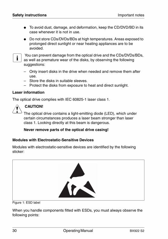
Modules with Electrostatic-Sensitive Devices
Modules with electrostatic-sensitive devices are identified by the following sticker:
Figure 1: ESD label
When you handle components fitted with ESDs, you must always observe the following points:

BX922 S2 Operating Manual 31
Important notes CE conformity
● Switch off the system and remove the power plugs from the power outlets before installing or removing components with ESDs.
● You must always discharge static build-up (e.g. by touching a grounded object) before working with such components.
● Any devices or tools that are used must be free of electrostatic charge.
● Wear a suitable grounding cable that connects you to the external chassis of the system unit.
● Always hold components with ESDs at the edges or at the points marked green (touch points).
● Do not touch any connectors or conduction paths on an ESD.
● Place all the components on a pad which is free of electrostatic charge.
I For a detailed description of how to handle ESD components, see the relevant European or international standards (EN 61340-5-1, ANSI/ESD S20.20).
Other important information:
● During cleaning, observe the instructions in section "Cleaning the Server Blade" on page 51.
● Keep this operating manual and the other documentation (such as the technical manual, documentation DVD) close to the device. All documentation must be included if the equipment is passed on to a third party.
3.2 CE conformity
The system complies with the requirements of the EC directives 2004/108/EC regarding "Electromagnetic Compatibility" and 2006/95/EC "Low Voltage Directive". This is indicated by the CE marking (CE = Communauté Européenne).

32 Operating Manual BX922 S2
FCC class A device Important notes
© c
ogni
tas.
Ges
ells
chft
für
Tech
nik-
Dok
ume
ntat
ion
mb
H 2
010
P
fad:
C:\P
rogr
am
me\
FC
T\ti
m_a
pp\ti
m_l
oca
l\wor
k\W
ALT
ER
\OB
J_D
OK
U-4
960-
001
.fm
3.3 FCC class A device
V Warning!
This is class A product, which may cause radio interference in a domestic environment. If this is the case, the user may be required to take adequate measures.
3.4 Transporting the Server Blade
V CAUTION!
Only transport the server blade in its original packaging or in suitable packaging which protects it from knocks and jolts. Do not unpack the server blade until it is at its installation location.
3.5 Notes on installation in the system unit
V CAUTION!
Beware of the energy hazard at the midplane contacts of the system unit. A short circuit on these contacts may damage the system.

BX922 S2 Operating Manual 33
Important notes Environmental protection
3.6 Environmental protection
Environmentally-friendly product design and development
This product has been designed in accordance with the Fujitsu standard for "environmentally friendly product design and development". This means that key factors such as durability, selection and labeling of materials, emissions, packaging, ease of dismantling and recycling have been taken into account.
This saves resources and thus reduces the harm done to the environment. Further information can be found at:
– http://ts.fujitsu.com/products/standard_servers/index.html (for the EMEA market)
– http://primeserver.fujitsu.com/primergy/concept/ (for the Japanese market)
Energy-saving information
Devices that do not need to be constantly switched on should be switched off until they are needed as well as during long breaks and after completion of work.
Packaging information
This packaging information doesn’t apply to the Japanese market.
Do not throw away the packaging. You may need it later for transporting the system. If possible, the equipment should only be transported in its original packaging.
Information on handling consumables
Please dispose of printer consumables and batteries in accordance with the applicable national regulations.
In accordance with EU directives, batteries must not be disposed of with unsorted domestic waste. They can be returned free of charge to the manufacturer, dealer or an authorized agent for recycling or disposal.

34 Operating Manual BX922 S2
Environmental protection Important notes
© c
ogni
tas.
Ges
ells
chft
für
Tech
nik-
Dok
ume
ntat
ion
mb
H 2
010
P
fad:
C:\P
rogr
am
me\
FC
T\ti
m_a
pp\ti
m_l
oca
l\wor
k\W
ALT
ER
\OB
J_D
OK
U-4
960-
001
.fm
All batteries containing pollutants are marked with a symbol (a crossed-out garbage can). They are also marked with the chemical symbol for the heavy metal that causes them to be categorized as containing pollutants:
Cd CadmiumHg MercuryPb Lead
Labels on plastic casing parts
Please avoid sticking your own labels on plastic parts wherever possible, since this makes it difficult to recycle them.
Returns, recycling and disposal
Please handle returns, recycling and disposal in accordance with local regulations.
Details regarding the return and recycling of devices and consumables within Europe can also be found in the "Returning used devices" manual, via your local Fujitsu branch or from our recycling center in Paderborn:
Fujitsu Technology SolutionsRecycling CenterD-33106 Paderborn
Tel. +49 5251 8 18010
Fax +49 5251 8 333 18010
The device must not be disposed of with domestic waste. This device is labeled in compliance with European directive 2002/96/EC on waste electrical and electronic equipment (WEEE).
This directive sets the framework for returning and recycling used equipment and is valid across the EU. When returning your used device, please use the return and collection systems available to you. Further information can be found at http://ts.fujitsu.com/recycling.

BX922 S2 Operating Manual 35
4 Installing the hardwareV CAUTION!
● Follow the safety instructions in the chapter "Important notes" on page 25.
● Do not expose the server to extreme environmental conditions (see "Ambient conditions" on page 21). Protect the server from dust, humidity and heat.
● Make sure that the server is acclimatized for the time indicated in this table before putting it into operation.
In the table "Acclimatization time", the temperature difference refers to the difference between the operating environment temperature and the temperature to which the server was exposed previously (outside, transport or storage temperature).
Temperature difference (°C) Minimum acclimatization time (hours)
5 3
10 5
15 7
20 8
25 9
30 10
Table 1: Acclimatization time

36 Operating Manual BX922 S2
Unpacking the server Installing the hardware
© c
ogni
tas.
Ges
ells
chft
für
Tech
nik-
Dok
ume
ntat
ion
mb
H 2
010
P
fad:
C:\P
rogr
am
me\
FC
T\ti
m_a
pp\ti
m_l
oca
l\wor
k\W
ALT
ER
\OB
J_D
OK
U-4
961-
001
.fm
4.1 Unpacking the server
V CAUTION!
Follow the safety instructions in chapter "Important notes" on page 25.
The server must always be lifted or carried by at least two people.(For the Japanese market, please refer to "安全上の注意およびその他の重要情報 ".)
Do not unpack the server until it is at its installation location.
Ê Transport the server to the place where you want to set it up.
Ê Unpack all individual parts.
Keep the original packaging in case you want to transport the server again (applies only to EMEA market).
Ê Check the delivery for any damage during transport.
Ê Check whether the items delivered match the details on the delivery note.
The product name and serial number of the product can be found on the ID card.
Ê Notify your supplier immediately should you discover that the items delivered do not correspond to the delivery note.
4.2 Installing the Server Blade in the system unit
V CAUTION!
● Note the safety instructions and the information on handling electrostatically sensitive devices in section "Safety instructions" on page 25.
● Note the population rules for power supply units and fan modules to ensure sufficient cooling of the system. You will find more detailed information on this in the operating manual for the BX900 S1 system unit.
BX922 S2 Operating Manual 37
Installing the hardware Installing the Server Blade in the system unit
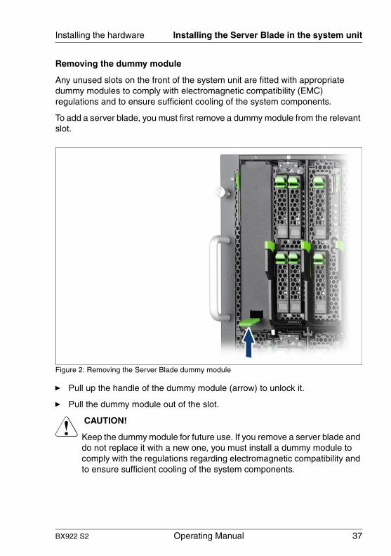
Removing the dummy module
Any unused slots on the front of the system unit are fitted with appropriate dummy modules to comply with electromagnetic compatibility (EMC) regulations and to ensure sufficient cooling of the system components.
To add a server blade, you must first remove a dummy module from the relevant slot.
Figure 2: Removing the Server Blade dummy module
Ê Pull up the handle of the dummy module (arrow) to unlock it.
Ê Pull the dummy module out of the slot.
V CAUTION!
Keep the dummy module for future use. If you remove a server blade and do not replace it with a new one, you must install a dummy module to comply with the regulations regarding electromagnetic compatibility and to ensure sufficient cooling of the system components.

38 Operating Manual BX922 S2
Installing the Server Blade in the system unit Installing the hardware
© c
ogni
tas.
Ges
ells
chft
für
Tech
nik-
Dok
ume
ntat
ion
mb
H 2
010
P
fad:
C:\P
rogr
am
me\
FC
T\ti
m_a
pp\ti
m_l
oca
l\wor
k\W
ALT
ER
\OB
J_D
OK
U-4
961-
001
.fm
Installing the dummy module
To install the dummy module, follow the same procedure as for removing it, except in reverse order.
Installing the Server Blade
V CAUTION!
Follow the safety instructions and information in section "Modules with Electrostatic-Sensitive Devices" on page 30.
Figure 3: Installing the Server Blade
Ê Open the release lever (1).
Ê Push the server blade as far as possible into the slot.

BX922 S2 Operating Manual 39
Installing the hardware Installing the Server Blade in the system unit
Figure 4: Locking the Server Blade
Ê Pull the release lever up until it engages.
Removal is carried out in reverse order.
V CAUTION!
If you remove a server blade and do not replace it with a new one, you must install a dummy module to comply with the regulations regarding electromagnetic compatibility and to ensure sufficient cooling of the system components.
40 Operating Manual BX922 S2
Connecting devices Installing the hardware
© c
ogni
tas.
Ges
ells
chft
für
Tech
nik-
Dok
ume
ntat
ion
mb
H 2
010
P
fad:
C:\P
rogr
am
me\
FC
T\ti
m_a
pp\ti
m_l
oca
l\wor
k\W
ALT
ER
\OB
J_D
OK
U-4
961-
001
.fm
4.3 Connecting devices
All connections that are required to operate the server blade are made via the midplane of the PRIMERGY BX900 system unit. When the server blade is installed, midplane contacts automatically establish connections to the infrastructure modules on the rear of the system unit:
– Power supply units
– Management blade(s) for server administration
– Ethernet and/or fiber-channel connection blades for connection to a LAN or SAN
You can find information about the external ports of the BX900 system unit in the relevant operating manual.
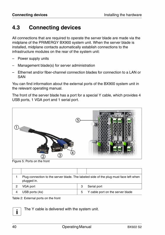
The front of the server blade has a port for a special Y cable, which provides 4 USB ports, 1 VGA port and 1 serial port.
Figure 5: Ports on the front
I The Y cable is delivered with the system unit.
1 Plug connection to the server blade. The labeled side of the plug must face left when plugged in.
2 VGA port 3 Serial port
4 USB ports (4x) 5 Y cable port on the server blade
Table 2: External ports on the front

BX922 S2 Operating Manual 41
Installing the hardware Instructions for connecting/disconnecting cables
4.4 Instructions for connecting/disconnecting cables
V CAUTION!
Be sure to read the documentation for the peripheral devices before connecting them.
Do not connect or disconnect data cables during a thunderstorm.
When removing a cable, always hold it by the plug. Never unplug a cable by pulling at the cable itself.
Connect and disconnect the cables in the order described below.
Connecting cables
Ê Turn off all power and equipment switches.
Ê Disconnect all power plugs from the grounded shockproof sockets.
Ê Connect all cables to the server and peripherals.
Ê Plug all data communication cables into the utility sockets.
Ê Plug all power cables into the grounded shockproof sockets.
Disconnecting cables
Ê Turn off all power and equipment switches.
Ê Disconnect all power plugs from the grounded shockproof sockets.
Ê Unplug all data communication cables from the utility sockets.
Ê Disconnect the relevant cables from the server and all the peripherals.
42 Operating Manual BX922 S2
Instructions for connecting/disconnecting cables Installing the hardware
© c
ogni
tas.
Ges
ells
chft
für
Tech
nik-
Dok
ume
ntat
ion
mb
H 2
010
P
fad:
C:\P
rogr
am
me\
FC
T\ti
m_a
pp\ti
m_l
oca
l\wor
k\W
ALT
ER
\OB
J_D
OK
U-4
961-
001
.fm

BX922 S2 Operating Manual 43
5 Installation and operationV CAUTION!
Follow the safety instructions in the chapter "Important notes" on page 25.
5.1 Control and display elements
Figure 6: Control and display elements
1 I/O indicator: fabric 1 5 Global Error indicator
2 I/O indicator: fabric 2 6 ID button with ID indicator
3 I/O indicator: fabric 3/4 7 On/Off button with power-on indicator
4 CSS indicator

44 Operating Manual BX922 S2
Control and display elements Installation and operation
© c
ogni
tas.
Ges
ells
chft
für
Tech
nik-
Dok
ume
ntat
ion
mb
H 2
010
P
fad:
C:\P
rogr
am
me\
FC
T\ti
m_a
pp\ti
m_l
oca
l\wor
k\W
ALT
ER
\OB
J_D
OK
U-4
962-
001
.fm
Control elements
LEDs on the control panel
On/Off button
When the system is switched off, it can be switched on again by pressing the On/Off button.
When the system is operating, pressing the On/Off button will switch off the system.
I The On/Off button does not disconnect the server from the mains voltage. To disconnect from the mains completely, remove the power plug(s).
ID ID button
Lights up (blue) on the front and on the rear of the system unit when the ID button is pressed. The two ID indicators are synchronized.
Power indicator (two-color)
Does not light up if no line voltage is present.
Lights red when the server is switched off but line voltage is present.
Lights orange (red and green at the same time) to indicate a power supply error.
Lights up green when the server is switched on.
Flashes green when the server has been switched on and is in standby mode.

BX922 S2 Operating Manual 45
Installation and operation Control and display elements
Global Error indicator (orange)
– Lights up orange if a prefailure event has been detected that requires (precautionary) service intervention.
– Flashes orange if an error was detected that requires service intervention.
– Does not light up if there is no critical event.
If the event is still acute after a power failure, the indicator is activated after the restart.
The indicator also lights up in standby mode.
You can find more details on the indicated errors in the System Event Log (SEL), on the ServerView Local Service Panel, on the ServerView Local Service Display, in the ServerView Operations Manager or via the iRMC S2's Web interface.
CSS CSS indicator (yellow)
– Lights up yellow if a prefailure event was detected for a CSS component that you can fix yourself (for reasons of precaution) with the CSS concept.
– Flashes yellow if an error was detected that you can fix yourself with the CSS concept.
– Does not light up when the system is OK.
If the event is still acute after a power failure, the indicator is activated after the restart.
The indicator also lights up in standby mode.
For more information on the CSS concept, see "Customer Self Service (CSS)" on page 13.
ID ID indicator (blue)
Lights up blue when the system has been selected by pressing the ID button. To deactivate, press the button again.
The ID indicator can also be activated via the ServerView Operations Manager and the iRMC S2 Web interface and its status reported to the ServerView Operations Manager and the iRMC S2.
!

46 Operating Manual BX922 S2
Control and display elements Installation and operation
© c
ogni
tas.
Ges
ells
chft
für
Tech
nik-
Dok
ume
ntat
ion
mb
H 2
010
P
fad:
C:\P
rogr
am
me\
FC
T\ti
m_a
pp\ti
m_l
oca
l\wor
k\W
ALT
ER
\OB
J_D
OK
U-4
962-
001
.fm
Status indicators for the I/O fabrics* (green)
– Lights up to indicate a network connection.– Flashes to indicate an active network connection.– Does not light up if there is no network connection.
* The three I/O fabrics of the server blade are:
Fabric 1: onboard LAN controller
Fabric 2: mezzanine card 1
Fabric 3/4: mezzanine card 2

BX922 S2 Operating Manual 47
Installation and operation Switching the Server Blade on and off
5.2 Switching the Server Blade on and off
V CAUTION!
If you switch the server blade on and flickering stripes appear on the connected monitor, switch the server blade off again immediately (see chapter "Troubleshooting and tips" on page 85).
The On/Off button does not disconnect the device from the mains. To fully disconnect the device from the mains, you must remove the server blade from the system unit or switch off the system unit and unplug the power plug(s).
Using the control panel to switch the Server Blade on and off
The system unit is switched on and the power-on indicator (item 7 in figure 6 on page 43) is flashing green.
The server blade can be switched on and off as follows:
– To switch the server blade on, press the On/Off button on the server blade (item 7 in figure 6 on page 43).
To switch the server blade off, hold down the On/Off button on the server blade (item 7 in figure 6 on page 43) for 4 seconds.
Defined switch-on/off time
The server blade is switched on and off at the times defined in the ServerView Operation Manager.
Other On/Off options
– After power failure
Once a server blade has been switched on, it will switch itself on again automatically after a power failure (irrespective of the setting in the BIOS Setup).
I You can also switch the server blade on and off via the system unit control panel or via the Web interface of the ServerView Management Blade. Detailed information is provided in the manual "PRIMERGY BX900 Blade Server Systems ServerView Management Blade S1 User Interface Description".

48 Operating Manual BX922 S2
Configuring the Server Blade Installation and operation
© c
ogni
tas.
Ges
ells
chft
für
Tech
nik-
Dok
ume
ntat
ion
mb
H 2
010
P
fad:
C:\P
rogr
am
me\
FC
T\ti
m_a
pp\ti
m_l
oca
l\wor
k\W
ALT
ER
\OB
J_D
OK
U-4
962-
001
.fm
5.3 Configuring the Server Blade
This section contains information about configuring the server blade and installing the operating system.
The operating system can be installed in various ways:
– Local installation with or without the ServerView Installation Manager
You can find information on local installation in the following sections.
– Remote installation using console redirection via the user interface of the ServerView Management Blade
You can find information on console redirection in the manual "PRIMERGY BX900 Blade Server Systems ServerView Management Blade S1 User Interface Description". Apart from this, the operating system installation is carried out in the same way as a local installation.
– Importing the clone images from an image repository to the desired server blades.
For more information about this procedure, see the "ServerView Deployment Manager 5.0" manual (on PRIMERGY ServerView Suite DVD 2 under Industry Standard Servers - Software - ServerView Suite - Server Installation and Deployment).
5.3.1 Preparing for local installation
Connect the monitor, mouse, keyboard and a DVD drive to the port on the server blade control panel with the aid of the special Y cable. See "Connecting devices" on page 40.
I Make sure that the energy saving functions are disabled in the Power menu of the BIOS Setup during operation, and that the DVD drive has been activated as a boot medium.
5.3.2 Configuring the onboard SATA controller
A 6-port SATA controller is integrated on the system board. You can configure the onboard SATA controller either before or during installation with the ServerView Installation Manager. Using the ServerView Installation Manager is recommended.

BX922 S2 Operating Manual 49
Installation and operation Configuring the Server Blade
I The controller has its own configuration utility. For further information, refer to the “Embedded MegaRAID Software User’s Guide” (on the PRIMERGY ServerView Suite DVD 2 under Industry Standard Servers - Expansion Cards - Storage Adapters - LSI RAID / SCSI Controllers).
I Descriptions of operating systems not covered in the controller manual are provided in the corresponding readme files on the driver CDs.
5.3.3 Configuring the server and installing the operating system with the ServerView Installation Manager
Using the ServerView Installation Manager on the PRIMERGY ServerView Suite DVD 1 provided, you can conveniently configure the server and install the operating system. This includes configuring the server-specific settings using the ServerView Configuration Manager and configuring the RAID controller using the ServerView RAID Manager.
Advantages of the ServerView Installation Manager
– Wizard assisted configuration of your server hardware and disk arrays
– Wizard assisted installation of all leading server operating systems
– Wizard-assisted creation of configuration files for unattended installation of several PRIMERGY servers with identical hardware configurations.
– Installation of drivers and additional software.
I The software that can be installed depends on your server’s hardware configuration. This configuration is detected automatically.
I Descriptions of operating systems not covered in the RAID controller manual are provided in the corresponding readme files on the driver CDs.
To find out how to operate the ServerView Installation Manager and for further information, refer to the associated manual.
If you are using the ServerView Installation Manager, you can skip the following section on how to configure the server and install the operating system. Continue from section "Cleaning the Server Blade" on page 51.

50 Operating Manual BX922 S2
Configuring the Server Blade Installation and operation
© c
ogni
tas.
Ges
ells
chft
für
Tech
nik-
Dok
ume
ntat
ion
mb
H 2
010
P
fad:
C:\P
rogr
am
me\
FC
T\ti
m_a
pp\ti
m_l
oca
l\wor
k\W
ALT
ER
\OB
J_D
OK
U-4
962-
001
.fm
5.3.4 Configuring the server and installing the operating system without ServerView Installation Manager
onboard SATA controller, configuring
Configure the controller as described in section "Configuring the onboard SATA controller" on page 48.
Installing the operating system
Ê Insert the DVD for the operating system you want to install.
Ê Reboot the server blade.
Ê Follow the instructions on screen and in the manual for the operating system.
BX922 S2 Operating Manual 51
Installation and operation Cleaning the Server Blade
5.4 Cleaning the Server Blade
V CAUTION!
Switch off the server blade and remove it from the system unit (see page 38).
Do not clean any interior parts of the server blade yourself; leave this job to a service technician.
Do not use abrasive powder or detergents which dissolve plastic to clean the housing exterior.
Make sure that no liquid gets inside the device and that the ventilation slits on the ServerBlade remain open.
Wipe the server blade housing with a dry cloth to clean. If it is very dirty you can use a damp cloth that has been dipped in water with a mild detergent and well wrung out.
52 Operating Manual BX922 S2
Cleaning the Server Blade Installation and operation
© c
ogni
tas.
Ges
ells
chft
für
Tech
nik-
Dok
ume
ntat
ion
mb
H 2
010
P
fad:
C:\P
rogr
am
me\
FC
T\ti
m_a
pp\ti
m_l
oca
l\wor
k\W
ALT
ER
\OB
J_D
OK
U-4
962-
001
.fm
BX922 S2 Operating Manual 53
BIOS Setup
6 BIOS SetupYou can set the system functions and the hardware configuration of a server blade in the BIOS Setup.
I The range of BIOS parameters displayed can vary according to the configuration.
The default settings are effective when the server blade is delivered. You can change these settings in the BIOS Setup. The changes take effect as soon as you save them and exit the BIOS Setup.
The following overviews illustrate how the BIOS Setup menus are structured. The numbers in brackets refer to the pages that contain the relevant descriptions.
SysInfo – System Overview
System Information, Page 1 [ 59]
System Information, Page 2 [ 60]
Main – System Overview
System Time / System Date [ 61]
Sync RTC with Mgmt. Blade [ 61]
Boot Features [ 62]
POST Errors [ 62]
NumLock [ 62]
Fast Boot [ 62]
POST Diagnostic Screen [ 62]
Boot Menu [ 62]
System Memory / Extended Memory [ 62]
Advanced – Advanced Settings
Reset Configuration Data [ 63]
Peripheral Configuration [ 63]
Serial [ 64]
Serial Port 1 Address [ 64]
USB Host Controller [ 64]
USB Speed [ 64]

54 Operating Manual BX922 S2
BIOS Setup
© c
ogni
tas.
Ges
ells
chft
für
Tech
nik-
Dok
ume
ntat
ion
mb
H 2
010
P
fad:
C:\P
rogr
am
me\
FC
T\ti
m_a
pp\ti
m_l
oca
l\wor
k\W
ALT
ER
\OB
J_D
OK
U-4
963-
001
.fm
Advanced – Advanced Settings (continued)
USB Devices [ 64]
SATA AHCI Enable [ 64]
LAN Controller n [ 64]
Port n Remote Boot [ 65]
Mezzanine card n: type Remote Boot [ 65]
Advanced System Configuration [ 64]
High Precision Event Timer [ 66]
I/OAT [ 66]
Advanced Memory Options [ 64]
Memory scrubbing [ 66]
Memory Redundancy [ 66]
Memory Power Mode [ 66]
NUMA Optimization [ 66]
Advanced Processor Options [ 64]
CPU Mismatch Detection [ 67]
Core Multi-Processing [ 67]
Enhanced SpeedStep [ 67]
Enhanced Idle Power State [ 67]
Virtualization Tech (VT-x) [ 67]
Virtualization Tech (VT-d) [ 67]
NX Memory Protection [ 67]
Adjacent Cache Line Prefetch [ 68]
Hardware Prefetch [ 68]
Limit CPUID Function [ 68]
Security – Security Settings
Supervisor Password / User Password [ 69]
Set Supervisor Password [ 69]
Set User Password [ 69]
Flash Write [ 69]
Power – Power Settings
Power Failure Recovery [ 70]
BX922 S2 Operating Manual 55
BIOS Setup
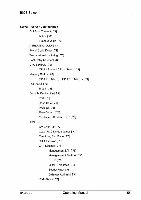
Server – Server Configuration
O/S Boot Timeout [ 72]
Action [ 72]
Timeout Value [ 73]
ASR&R Boot Delay [ 73]
Power Cycle Delay [ 73]
Temperature Monitoring [ 73]
Boot Retry Counter [ 73]
CPU STATUS [ 73]
CPU 1 Status / CPU 2 Status [ 74]
Memory Status [ 73]
CPU 1: DIMM x,y / CPU 2: DIMM x,y [ 74]
PCI Status [ 73]
Slot x [ 75]
Console Redirection [ 73]
Port [ 76]
Baud Rate [ 76]
Protocol [ 76]
Flow Control [ 76]
Continue C.R. after POST [ 76]
IPMI [ 73]
SM Error Halt [ 77]
Load iRMC Default Values [ 77]
Event Log Full Mode [ 77]
SDRR Version [ 77]
LAN Settings [ 77]
Management LAN [ 78]
Management LAN Port [ 78]
DHCP [ 78]
Local IP Address [ 78]
Subnet Mask [ 78]
Gateway Address [ 79]
IPMI Status [ 77]

56 Operating Manual BX922 S2
Access BIOS Setup
© c
ogni
tas.
Ges
ells
chft
für
Tech
nik-
Dok
ume
ntat
ion
mb
H 2
010
P
fad:
C:\P
rogr
am
me\
FC
T\ti
m_a
pp\ti
m_l
oca
l\wor
k\W
ALT
ER
\OB
J_D
OK
U-4
963-
001
.fm
The following sections describe the individual menus and their settings as well as how to access and operate the BIOS Setup. Default values are displayed in bold.
6.1 Access
Ê Start the server blade in cold boot or warm boot mode.
Ê Press the function key [F2].
Ê Enter the Setup password (if assigned) and confirm your entry by pressing the Return key.
Server – Server Configuration (continued)
IPMI Specification Version [ 79]
iRMC Hardware [ 79]
iRMC Firmware Version [ 79]
Boot – Boot Priority Order
1st Boot Device / 2nd Boot Device / 3rd Boot Device [ 80]
Exit – Exit Options
Save Changes and Exit [ 81]
Discard Changes and Exit [ 81]
Get Default Values [ 81]
Load Previous Values [ 81]
BX922 S2 Operating Manual 57
BIOS Setup Operation
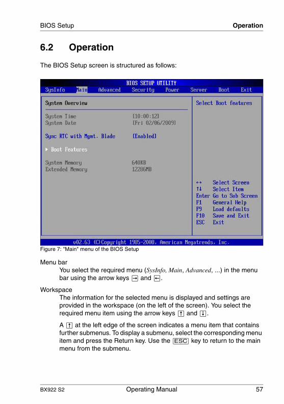
6.2 Operation
The BIOS Setup screen is structured as follows:
Figure 7: "Main" menu of the BIOS Setup
Menu barYou select the required menu (SysInfo, Main, Advanced, ...) in the menu bar using the arrow keys À and Â.
WorkspaceThe information for the selected menu is displayed and settings are provided in the workspace (on the left of the screen). You select the required menu item using the arrow keys Ê and Ë.
A Ê at the left edge of the screen indicates a menu item that contains further submenus. To display a submenu, select the corresponding menu item and press the Return key. Use the [ESC] key to return to the main menu from the submenu.

58 Operating Manual BX922 S2
Operation BIOS Setup
© c
ogni
tas.
Ges
ells
chft
für
Tech
nik-
Dok
ume
ntat
ion
mb
H 2
010
P
fad:
C:\P
rogr
am
me\
FC
T\ti
m_a
pp\ti
m_l
oca
l\wor
k\W
ALT
ER
\OB
J_D
OK
U-4
963-
001
.fm
Square brackets ([ ]) surrounding a parameter value indicate that this value can be changed using the [+] and [-] keys. If the parameter comprises several input areas, e.g. time and date entries, you can use the [Tab] key to move between the individual areas.
An asterisk (*) in front of a menu item indicates configuration conflicts that must be resolved.
Information areaThe information area (on the right of the screen) displays brief information on the selected menu item as well as information on how to operate the BIOS Setup.

BX922 S2 Operating Manual 59
BIOS Setup SysInfo menu
6.3 SysInfo menu
Figure 8: "SysInfo" BIOS Setup menu, page 1
System Information, Page 1Displays information concerning the BIOS, CPU and various IDs.

60 Operating Manual BX922 S2
SysInfo menu BIOS Setup
© c
ogni
tas.
Ges
ells
chft
für
Tech
nik-
Dok
ume
ntat
ion
mb
H 2
010
P
fad:
C:\P
rogr
am
me\
FC
T\ti
m_a
pp\ti
m_l
oca
l\wor
k\W
ALT
ER
\OB
J_D
OK
U-4
963-
001
.fm
Figure 9: "SysInfo" BIOS Setup menu, page 2
System Information, Page 2Displays information on LAN MAC addresses (including the LAN MAC address of the iRMC) and COM ports.

BX922 S2 Operating Manual 61
BIOS Setup Main menu
6.4 Main menu
Figure 10: "Main" menu of the BIOS Setup
System Time / System DateSets the system time and the system date.
The system time format is HH:MM:SS. The system date format is WeekdayMM/DD/YYYY. By pressing Ú, [Tab] or Í+[Tab] you can position the cursor within the relevant input field and configure the values using [+] or [-].
I If the system time and date are wrong after you switch off your server and restart it, the lithium battery is flat and needs to be changed.
Sync RTC with Mgmt. BladeSwitches the synchronization of the Real-Time Clock with the time of the management blade on (Enabled) or off (Disabled).
I If this item is set to (Enabled), the "System Time" and "System Date" entries cannot be selected.

62 Operating Manual BX922 S2
Main menu BIOS Setup
© c
ogni
tas.
Ges
ells
chft
für
Tech
nik-
Dok
ume
ntat
ion
mb
H 2
010
P
fad:
C:\P
rogr
am
me\
FC
T\ti
m_a
pp\ti
m_l
oca
l\wor
k\W
ALT
ER
\OB
J_D
OK
U-4
963-
001
.fm
Boot FeaturesCalls a submenu with the options during the boot process (see page 62).
System Memory / Extended MemoryShows the size of the available main memory.
6.4.1 Boot Features menu
POST ErrorsSpecifies whether the system will be stopped (Enabled) or not (Disabled) if an error occurs during the boot process.
NumLock Specifies whether NumLock (for the numeric keypad) is set (On) or not (Off) after you have switched the server on.
Fast BootSpecifies whether the boot process is speeded up (Enabled) or not (Disabled) by bypassing certain tests.
POST Diagnostic ScreenSpecifies whether the diagnosis screen is displayed (Enabled) or not (Disabled) during the boot phase.
Boot MenuEnables you to avoid the "normal" sequence of boot devices. Press [F12] before the operation system is loaded, and then select an alternative boot device.
EnabledThe boot menu is displayed if you press [F12].
DisabledThe boot menu is not available. The boot devices are addressed in the specified sequence.
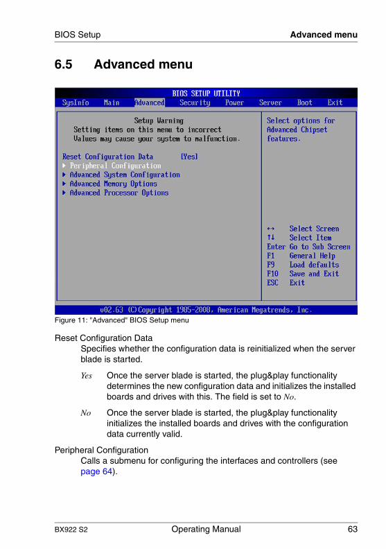
BX922 S2 Operating Manual 63
BIOS Setup Advanced menu
6.5 Advanced menu
Figure 11: "Advanced" BIOS Setup menu
Reset Configuration DataSpecifies whether the configuration data is reinitialized when the server blade is started.
Yes Once the server blade is started, the plug&play functionality determines the new configuration data and initializes the installed boards and drives with this. The field is set to No.
No Once the server blade is started, the plug&play functionality initializes the installed boards and drives with the configuration data currently valid.
Peripheral ConfigurationCalls a submenu for configuring the interfaces and controllers (see page 64).

64 Operating Manual BX922 S2
Advanced menu BIOS Setup
© c
ogni
tas.
Ges
ells
chft
für
Tech
nik-
Dok
ume
ntat
ion
mb
H 2
010
P
fad:
C:\P
rogr
am
me\
FC
T\ti
m_a
pp\ti
m_l
oca
l\wor
k\W
ALT
ER
\OB
J_D
OK
U-4
963-
001
.fm
Advanced System ConfigurationCalls a submenu for configuring the PCI slots and PCI components on the motherboard (see page 66).
Advanced Memory Options Calls a submenu for specifying the memory properties (see page 66).
Advanced Processor OptionsCalls a submenu for specifying the CPU properties (see page 67).
6.5.1 Peripheral Configuration
The "Peripheral Configuration" submenu contains the following items:
Serial Use this input field to activate (Enabled) or deactivate (Disabled) the serial port.
Serial Port 1 AddressSpecifies the base I/O address and the interrupt for the serial port (3F8h/IRQ4, 2F8h/IRQ3, 3E8h/IRQ4, 2E8h/IRQ3).
USB Host ControllerThis item allows the following USB settings:
USB Speed Specifies the speed at which the USB ports are operated.
USB 1.1The USB 2.0 high speed host controller is deactivated.
USB 1.1 & USB 2.0Both host controllers are activated.
USB Devices Specifies which USB devices (None, Keyboard And Mouse Only, All) are to be available after the boot process.
SATA AHCI EnableDefines whether the SSD drives are operated in AHCI mode (Enabled) or in IDE mode (Disabled).
LAN Controller n Specifies (for each controller) whether a port is activated by onboard LAN Controller n, and if so, which port.

BX922 S2 Operating Manual 65
BIOS Setup Advanced menu
DisabledNo port is activated.
Port 1PORT 1 is activated.
Port 1 & 2Both ports are activated.
Port n Remote Boot Specifies whether onboard LAN n OPROM is active during the POST.
DisabledThe function is deactivated.
PXEPXE is activated.
iSCSIiSCSI is activated.
I The "Port 1 Remote Boot" item does not appear if "LAN Controller n" is set to Disabled.
The "LAN Controller 1/Port 1 Remote Boot" item is usually set to PXE.
The "Port 2 Remote Boot" item is only displayed if "LAN Controller n" is set to Port 1&2.
Mezzanine card n: type Remote BootDefines whether the OPROM of he mezzanine card n of type Fibre Channel or Ethernet is active during the POST (Enabled) or not (Disabled).
I This item does not appear if the required mezzanine card is missing.

66 Operating Manual BX922 S2
Advanced menu BIOS Setup
© c
ogni
tas.
Ges
ells
chft
für
Tech
nik-
Dok
ume
ntat
ion
mb
H 2
010
P
fad:
C:\P
rogr
am
me\
FC
T\ti
m_a
pp\ti
m_l
oca
l\wor
k\W
ALT
ER
\OB
J_D
OK
U-4
963-
001
.fm
6.5.2 Advanced System Configuration
The "Advanced System Configuration" submenu contains the following items:
High Precision Event TimerSpecifies whether the High Precision Event Timer for time-critical applications (e.g. multimedia applications) is activated (Enabled) or deactivated (Disabled).
I/OATSpecifies whether the advanced hardware capabilities of Intel® I/O Acceleration Technology (I/OAT) is activated (Enabled) or deactivated (Disabled). This technology requires additional operating system and driver support.
6.5.3 Advanced Memory Options
You can make advanced memory configurations using the menu items in this submenu.
Memory scrubbingSpecifies whether memory scrubbing is activated (Enabled) or deactivated (Disabled).
Memory RedundancySpecifies whether memory redundancy is activated or deactivated (Disabled), and if so, what type (Mirroring, Sparing).
Memory Power ModeSpecifies which power mode is used for the memory modules.
Installing the Performance AdapterThe clock frequency at which the memory modules offer the best performance is selected automatically.
EnergyA clock frequency at which energy efficiency is at its highest is selected.
NUMA Optimization Specifies whether the non-uniform memory access optimization (NUMA)
is activated (Enabled) or deactivated (Disabled).
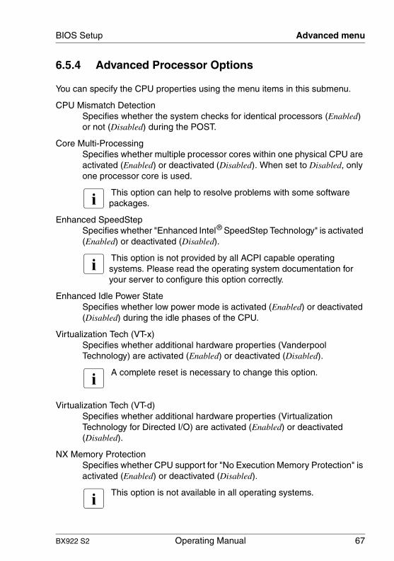
BX922 S2 Operating Manual 67
BIOS Setup Advanced menu
6.5.4 Advanced Processor Options
You can specify the CPU properties using the menu items in this submenu.
CPU Mismatch DetectionSpecifies whether the system checks for identical processors (Enabled) or not (Disabled) during the POST.
Core Multi-ProcessingSpecifies whether multiple processor cores within one physical CPU are activated (Enabled) or deactivated (Disabled). When set to Disabled, only one processor core is used.
I This option can help to resolve problems with some software packages.
Enhanced SpeedStepSpecifies whether "Enhanced Intel® SpeedStep Technology" is activated (Enabled) or deactivated (Disabled).
I This option is not provided by all ACPI capable operating systems. Please read the operating system documentation for your server to configure this option correctly.
Enhanced Idle Power StateSpecifies whether low power mode is activated (Enabled) or deactivated (Disabled) during the idle phases of the CPU.
Virtualization Tech (VT-x) Specifies whether additional hardware properties (Vanderpool Technology) are activated (Enabled) or deactivated (Disabled).
I A complete reset is necessary to change this option.
Virtualization Tech (VT-d) Specifies whether additional hardware properties (Virtualization Technology for Directed I/O) are activated (Enabled) or deactivated (Disabled).
NX Memory ProtectionSpecifies whether CPU support for "No Execution Memory Protection" is activated (Enabled) or deactivated (Disabled).
I This option is not available in all operating systems.
68 Operating Manual BX922 S2
Advanced menu BIOS Setup
© c
ogni
tas.
Ges
ells
chft
für
Tech
nik-
Dok
ume
ntat
ion
mb
H 2
010
P
fad:
C:\P
rogr
am
me\
FC
T\ti
m_a
pp\ti
m_l
oca
l\wor
k\W
ALT
ER
\OB
J_D
OK
U-4
963-
001
.fm
Adjacent Cache Line PrefetchSpecifies whether the CPU reads two cache lines ahead (Enabled) or just one (Disabled).
Hardware PrefetchSpecifies whether a hardware prefetch is activated (Enabled) or deactivated (Disabled).
I The use of this option depends on the various performance results for different applications.
Limit CPUID FunctionSpecifies whether CPUID commands are to be processed with more than 3 functions (Enabled) or not processed (Disabled).
I Some operating systems cannot handle new CPUID commands that have more than 3 functions. This option should be set to Enabled for these operating systems.
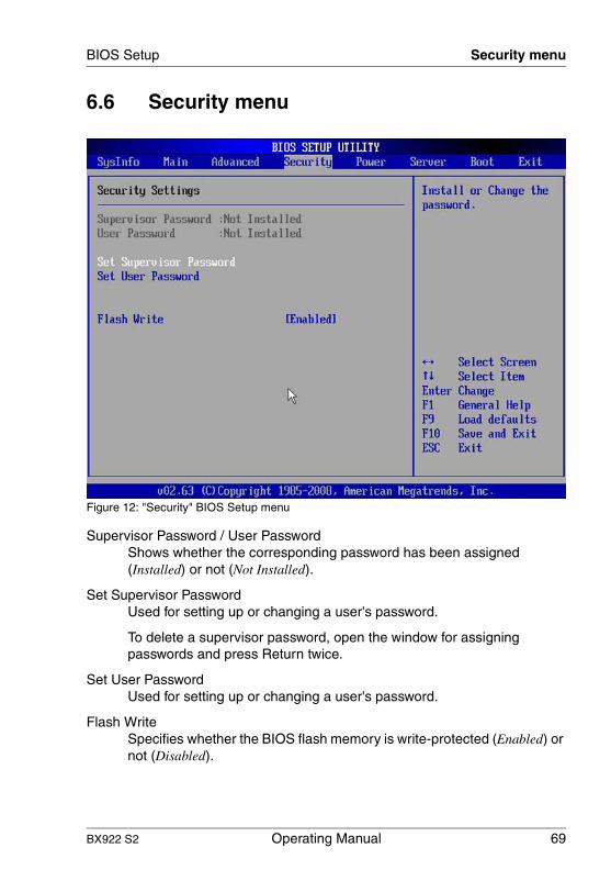
BX922 S2 Operating Manual 69
BIOS Setup Security menu
6.6 Security menu
Figure 12: "Security" BIOS Setup menu
Supervisor Password / User PasswordShows whether the corresponding password has been assigned (Installed) or not (Not Installed).
Set Supervisor PasswordUsed for setting up or changing a user's password.
To delete a supervisor password, open the window for assigning passwords and press Return twice.
Set User PasswordUsed for setting up or changing a user's password.
Flash WriteSpecifies whether the BIOS flash memory is write-protected (Enabled) or not (Disabled).

70 Operating Manual BX922 S2
Power menu BIOS Setup
© c
ogni
tas.
Ges
ells
chft
für
Tech
nik-
Dok
ume
ntat
ion
mb
H 2
010
P
fad:
C:\P
rogr
am
me\
FC
T\ti
m_a
pp\ti
m_l
oca
l\wor
k\W
ALT
ER
\OB
J_D
OK
U-4
963-
001
.fm
6.7 Power menu
Figure 13: "Power" BIOS Setup menu
Power-on SourceSpecifies whether power-on sources for ACPI operating systems are controlled by the BIOS or by the operating system.
BIOS ControlledPower-on sources are controlled by the BIOS. Switching on via LAN or timer is permitted.
ACPI ControlledPower-on sources are controlled by the ACPI operating system. Switching on is only possible via power switches.
Power Failure Recovery Specifies how the system behaves during recovery after a power failure.
Always OffSwitches the system off.

BX922 S2 Operating Manual 71
BIOS Setup Power menu
Always OnSwitches the system on.
Previous StateSwitches to the state the system was in before the power failure.

72 Operating Manual BX922 S2
Server menu BIOS Setup
© c
ogni
tas.
Ges
ells
chft
für
Tech
nik-
Dok
ume
ntat
ion
mb
H 2
010
P
fad:
C:\P
rogr
am
me\
FC
T\ti
m_a
pp\ti
m_l
oca
l\wor
k\W
ALT
ER
\OB
J_D
OK
U-4
963-
001
.fm
6.8 Server menu
Figure 14: "Server" BIOS Setup menu
O/S Boot TimeoutSpecifies whether a reset is performed (Enabled) or not (Disabled) after a specified timeout if the operating system could not be started.
Action Sets the action for a timeout of the operating system boot watchdog timer. The following actions can be configured:
ContinueContinue the boot process.
ResetPerform a reset.

BX922 S2 Operating Manual 73
BIOS Setup Server menu
Power CyclePerform a cold boot (Power Off / Power On).
I This item is only displayed if "O/S Boot Timeout" is set to Enabled.
Timeout Value Sets the boot watchdog timer of the operating system in minutes (0 ... 100).
I This item is only displayed if "O/S Boot Timeout" is set to Enabled.
ASR&R Boot DelaySpecifies the ASR&R boot delay time in minutes (1 ... 2 ... 30).
Power Cycle DelaySpecifies the delay between Power Off and the following Power On in seconds (0 ... 7 ... 15).
Temperature MonitoringSpecifies whether the system can still be started when reaching a critical temperature (Enabled) or not (Disabled).
Boot Retry Counter Specifies the number of boot attempts (0 ... 3 ... 7) after a failed boot process.
CPU STATUSCalls a submenu for specifying the CPU status (see page 74).
Memory Status Calls a submenu for specifying the memory status (see page 74).
PCI Status Calls a submenu for specifying the PCI status (see page 75).
Console Redirection Calls a submenu for specifying additional settings for the console (see page 76).
IPMI Calls a submenu for specifying the IPMI configuration and the Event Log (see page 77).

74 Operating Manual BX922 S2
Server menu BIOS Setup
© c
ogni
tas.
Ges
ells
chft
für
Tech
nik-
Dok
ume
ntat
ion
mb
H 2
010
P
fad:
C:\P
rogr
am
me\
FC
T\ti
m_a
pp\ti
m_l
oca
l\wor
k\W
ALT
ER
\OB
J_D
OK
U-4
963-
001
.fm
6.8.1 CPU STATUS
CPU 1 Status / CPU 2 StatusSpecifies the status of the installed CPUs. The status of an unpopulated CPU socket cannot be changed.
EnabledThe service processor stops the CPU upon request.
DisabledThe function is not activated.
FailedThe service processor stops the CPU due to an error.
6.8.2 Memory Status
CPU 1: DIMM x,y / CPU 2: DIMM x,ySpecifies the current status of the memory banks/memory modules:
EnabledIf the memory bank is populated, the system memory module is used.
DisabledThe memory module is not used by the system.
FailedIf an error occurs in a memory module and it cannot be corrected or if the system makes a memory correction too often, the status of the corresponding memory bank/memory module is automatically set to Failed.
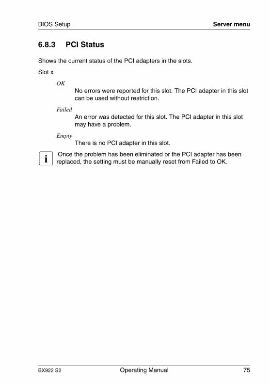
BX922 S2 Operating Manual 75
BIOS Setup Server menu
6.8.3 PCI Status
Shows the current status of the PCI adapters in the slots.
Slot x
OKNo errors were reported for this slot. The PCI adapter in this slot can be used without restriction.
FailedAn error was detected for this slot. The PCI adapter in this slot may have a problem.
EmptyThere is no PCI adapter in this slot.
I Once the problem has been eliminated or the PCI adapter has been replaced, the setting must be manually reset from Failed to OK.

76 Operating Manual BX922 S2
Server menu BIOS Setup
© c
ogni
tas.
Ges
ells
chft
für
Tech
nik-
Dok
ume
ntat
ion
mb
H 2
010
P
fad:
C:\P
rogr
am
me\
FC
T\ti
m_a
pp\ti
m_l
oca
l\wor
k\W
ALT
ER
\OB
J_D
OK
U-4
963-
001
.fm
6.8.4 Console Redirection
Port Specifies the port for communication with the terminal (Serial 1 or Disabled). The Disabled setting switches the terminal functionality off.
I When set to Disabled the other items in this submenu disappear.
Baud RateDefines the specified baud rate (115.2K, 57.6K, 38.4K, 19.2K, 9600).
I This item is only hidden if "Port" is set to Disabled.
ProtocolSpecifies the transfer protocol (ANSI, VT100, VT-UTF8, VT100+).
I This item is only hidden if "Port" is set to Disabled.
Flow ControlSpecifies how the transfer is controlled via the port. The setting (None, XON/XOFF) must be the same at both the terminal and server.
I This item is only hidden if "Port" is set to Disabled.
Continue C.R. after POSTSpecifies whether communication with the terminal is also possible whilst the operating system is being loaded (On) or not (Off).
I This item is only hidden if "Port" is set to Disabled.

BX922 S2 Operating Manual 77
BIOS Setup Server menu
6.8.5 IPMI
SM Error HaltSpecifies the behavior during a system management error or during configuration changes.
DisabledA warning message is displayed.
EnabledStops and shows Setup entries or a boot prompt.
Load iRMC Default ValuesSpecifies whether Event Logging is to load the manufacturer's settings (does not apply to entries that were configured by the BIOS Setup utility).
I The settings only become effective once you exit the BIOS Setup by choosing "Save Changes and Exit".
Yes Event Logging loads the manufacturer's settings (does not apply to entries that were configured by the BIOS Setup utility).
No Event Logging does not load the manufacturer's settings.
Event Log Full ModeSpecifies the Event Logging mode.
MaintainEvent Logging is stopped as soon as the SEL (System Event Log) is full.
OverwriteEvent Logging continues despite the SEL being full. The oldest entry is overwritten.
SDRR VersionShows the SDRR version number.
LAN SettingsCalls a submenu for specifying the LAN parameters for the iRMC (see page 78).
IPMI Status Calls a submenu for displaying information on the IPMI controller (see page 79).

78 Operating Manual BX922 S2
Server menu BIOS Setup
© c
ogni
tas.
Ges
ells
chft
für
Tech
nik-
Dok
ume
ntat
ion
mb
H 2
010
P
fad:
C:\P
rogr
am
me\
FC
T\ti
m_a
pp\ti
m_l
oca
l\wor
k\W
ALT
ER
\OB
J_D
OK
U-4
963-
001
.fm
6.8.5.1 LAN Settings
Management LAN Specifies whether communication between a remote system and the local iRMC is possible (Enabled) or not (Disabled).
Management LAN Port Specifies which LAN port (LAN 1, LAN 2) of the iRMC
service LAN is used. The iRMC uses the selected service LAN port for communication. The iRMC uses the system LAN port for communication.
I This item is only hidden if "Service LAN" is set to Disabled.
DHCPSpecifies whether DHCP support for the iRMC is activated (Enabled) or not (Disabled). It is recommended to use the same settings as those used for the network card.
I This item is only hidden if "Service LAN" is set to Disabled.
Local IP AddressEntry for configuring the IP address (000.000.000.000).
I This item is only hidden if "Service LAN" is set to Disabled. It is grayed out if "DHCP" is set to Enabled. It can be set if "DHCP" is set to Disabled.
Subnet MaskEntry for configuring the iRMC subnet mask (000.000.000.000). It is recommended to use the same settings as those used for the network card.
I This item is only hidden if "Service LAN" is set to Disabled. It is grayed out if "DHCP" is set to Enabled. It can be set if "DHCP" is set to Disabled.

BX922 S2 Operating Manual 79
BIOS Setup Server menu
Gateway AddressEntry for configuring the iRMC gateway address (192.168.002.203). It is recommended to use the same settings as those used for the network card.
I This item is only hidden if "Service LAN" is set to Disabled. It is grayed out if "DHCP" is set to Enabled. It can be set if "DHCP" is set to Disabled.
6.8.5.2 IPMI Status
IPMI Specification VersionIndicates the IPMI specification version.
iRMC HardwareIndicates the iRMC version.
iRMC Firmware VersionIndicates the iRMC firmware version.
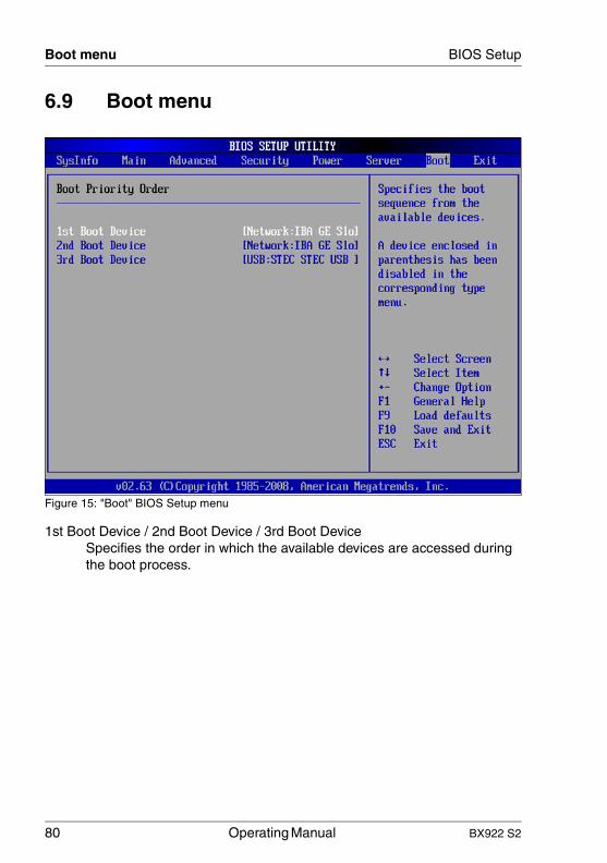
80 Operating Manual BX922 S2
Boot menu BIOS Setup
© c
ogni
tas.
Ges
ells
chft
für
Tech
nik-
Dok
ume
ntat
ion
mb
H 2
010
P
fad:
C:\P
rogr
am
me\
FC
T\ti
m_a
pp\ti
m_l
oca
l\wor
k\W
ALT
ER
\OB
J_D
OK
U-4
963-
001
.fm
6.9 Boot menu
Figure 15: "Boot" BIOS Setup menu
1st Boot Device / 2nd Boot Device / 3rd Boot Device Specifies the order in which the available devices are accessed during the boot process.
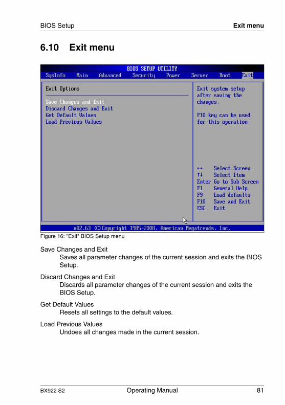
BX922 S2 Operating Manual 81
BIOS Setup Exit menu
6.10 Exit menu
Figure 16: "Exit" BIOS Setup menu
Save Changes and ExitSaves all parameter changes of the current session and exits the BIOS Setup.
Discard Changes and ExitDiscards all parameter changes of the current session and exits the BIOS Setup.
Get Default ValuesResets all settings to the default values.
Load Previous ValuesUndoes all changes made in the current session.

82 Operating Manual BX922 S2
Exit menu BIOS Setup
© c
ogni
tas.
Ges
ells
chft
für
Tech
nik-
Dok
ume
ntat
ion
mb
H 2
010
P
fad:
C:\P
rogr
am
me\
FC
T\ti
m_a
pp\ti
m_l
oca
l\wor
k\W
ALT
ER
\OB
J_D
OK
U-4
963-
001
.fm

BX922 S2 Operating Manual 83
7 Property and data protectionThe lockable rack door protects the server against unauthorized access.
To protect the system and data internally against unauthorized access, you can activate the security functions of the BIOSSetup.
7.1 BIOS Setup security functions
The Security menu in the BIOS Setup provides you with various options for protecting your data from unauthorized access. By combining these options, you can also achieve optimum protection for your system.
I A detailed description of the Security menu and how to assign passwords can be found in the BIOS Setup documentation on the PRIMERGY ServerBooks DVD.
Preventing unauthorized BIOS Setup calls
You can activate this protection by entering a setup password in the Security menu. You can also suppress the Press F2 for Setup message in this menu. This message is then no longer displayed while the server's startup routine is in progress.
Preventing unauthorized system access
You can activate this protection by entering a system password in the Security menu.
Preventing unauthorized access to the boards with their own BIOS
You can activate this protection by selecting the Extended item for Setup Password Lock field in the Security menu.
Preventing the system from booting from the floppy disk drive
You can activate this protection by selecting the item Diskette Lock for the System Load field in the Security menu.
84 Operating Manual BX922 S2
BIOS Setup security functions Property and data protection
© c
ogni
tas.
Ges
ells
chft
für
Tech
nik-
Dok
ume
ntat
ion
mb
H 2
010
P
fad:
C:\P
rogr
am
me\
FC
T\ti
m_a
pp\ti
m_l
oca
l\wor
k\W
ALT
ER
\OB
J_D
OK
U-4
964-
001
.fm
Preventing unauthorized writing to floppy disks
To activate this protection, select the value Disabled for the Diskette Write field in the Security menu.
Protecting BIOS from being overwritten
To activate this protection, select the value Disabled for the Flash Write field in the Security menu.
Protecting the server from being switched on by an external device
To activate this protection, select the value Disabled for the Remote Power On field in the Security menu.
Protecting the server from being switched off by a program
To activate this protection select the value Disabled for the Soft Power Off field in the Security menu.

BX922 S2 Operating Manual 85
8 Troubleshooting and tipsV CAUTION!
Follow the safety instructions in the "Safety notes and other important information" manual and in chapter "Important notes" on page 25.
If a fault occurs, attempt to resolve it using the measures described:
– in this chapter,– in the documentation for the connected devices,– in the help systems of the software used.
If you fail to correct the problem, proceed as follows:
Ê Make a list of the steps performed and the circumstances that led to the fault. Also make a list of any error messages that were displayed.
Ê Switch off the server.
Ê Contact our customer service team.
8.1 Server switches itself off
Server Management has detected an error
Ê Check the Event Log of the management blade or – if ServerView Operations Manager is installed – its error list or the ErrorLog file, and attempt to eliminate the error.
8.2 Screen remains blank1
Monitor is switched off
Ê Switch on your monitor.
1 In the case of a monitor connected locally via the Y cable, see "Connecting devices" on page 40.

86 Operating Manual BX922 S2
Flickering stripes on monitor screen Troubleshooting and tips
© c
ogni
tas.
Ges
ells
chft
für
Tech
nik-
Dok
ume
ntat
ion
mb
H 2
010
P
fad:
C:\P
rogr
am
me\
FC
T\ti
m_a
pp\ti
m_l
oca
l\wor
k\W
ALT
ER
\OB
J_D
OK
U-4
965-
001
.fm
Screen has gone blank
Ê Press any key on the keyboard.
or
Ê Deactivate screen saver. Enter the appropriate password.
Brightness control is set to dark
Ê Set the brightness control on the monitor to light. For detailed information, refer to the operating manual supplied with your monitor.
Power cable or monitor cable not connected
Ê Switch off the monitor and the server.
Ê Check whether the power cable is properly connected to the monitor and to the grounded socket.
Ê Check whether the monitor cable is properly connected to the server and monitor (if it is plugged in with a connector). If a separate graphics card is installed in the server, then the monitor cable must be connected to the graphics card.
Ê Switch on the monitor and the server.
8.3 Flickering stripes on monitor screen1
V CAUTION!
Switch off the server immediately. Risk of damaging the server.
Monitor does not support the set horizontal frequency
Ê Find out which horizontal frequency your monitor screen supports. You will find the horizontal frequency (also known as line frequency or horizontal deflection frequency) in the documentation for your monitor.
Ê Refer to the documentation for your operating system or the software for the screen controller for details of how to set the correct horizontal frequency for your monitor, and follow the procedure accordingly.
1 In the case of a monitor connected locally via the Y cable, see "Connecting devices" on page 40.
BX922 S2 Operating Manual 87
Troubleshooting and tips No screen display or display drifts
8.4 No screen display or display drifts1
The wrong horizontal frequency or resolution has been selected for the monitor or for the application program.
Ê Find out which horizontal frequency your monitor screen supports. You will find the horizontal frequency (also known as line frequency or horizontal deflection frequency) in the documentation for your monitor.
Ê Refer to the documentation for your operating system or the software for the screen controller for details of how to set the correct horizontal frequency for your monitor, and follow the procedure accordingly.
8.5 Incorrect date and time
Ê Set the date and time in the operating system or in the BIOS Setup under the Main menu, using System Date and System Time respectively.
I Note that the operating system may affect the system time. For example, the operating system time may deviate from the system time under Linux, and would overwrite the system time in the default setting on shutdown.
If the date and time are still wrong after the server has been switched off and back on again, replace the lithium battery (for a description refer to the Technical Manual for the D2861 system board) or contact our customer service team.
8.6 System will not boot
The system will not boot after installing a new hard disk drive.
SAS configuration incorrect
Ê Check the settings for the hard disk drives (SAS Device Configuration) and the additional settings in the SAS configuration menu.
1 In the case of a monitor connected locally via the Y cable, see "Connecting devices" on page 40.

88 Operating Manual BX922 S2
Hard disk drive error messages at system boot Troubleshooting and tips
© c
ogni
tas.
Ges
ells
chft
für
Tech
nik-
Dok
ume
ntat
ion
mb
H 2
010
P
fad:
C:\P
rogr
am
me\
FC
T\ti
m_a
pp\ti
m_l
oca
l\wor
k\W
ALT
ER
\OB
J_D
OK
U-4
965-
001
.fm
Power budget limit value exceeded
Ê Check whether the power budget limit value set in the management blade has been exceeded. You may need to install an additional power supply unit.
8.7 Hard disk drive error messages at system boot
Various hard disk drive error messages may appear when the system is rebooted. These error messages are caused by modifications in the selected RAID configuration.
RAID controller configuration incorrect
Ê Check and correct the settings for the drives using the RAID controller configuration program.
Further information can be found in the operating manual for the RAID controller.

BX922 S2 Operating Manual 89
Troubleshooting and tips Added drive reported as defective
8.8 Added drive reported as defective
RAID controller is not configured for this drive
The drive was probably installed when the system was switched off.
Ê Reconfigure the RAID controller for the drive using the corresponding utility. Information is provided in the documentation for the RAID controller.
or
Ê Remove and reinstall the drive while the system is switched ON.
If the hard disk drive continues to be shown as defective, then replace it (see "SSD hard disks" on page 92).
8.9 Error message on screen
The meaning of the error message is explained in the documentation for the relevant components and programs on the PRIMERGY ServerView Suite DVD 2.
90 Operating Manual BX922 S2
Error message on screen Troubleshooting and tips
© c
ogni
tas.
Ges
ells
chft
für
Tech
nik-
Dok
ume
ntat
ion
mb
H 2
010
P
fad:
C:\P
rogr
am
me\
FC
T\ti
m_a
pp\ti
m_l
oca
l\wor
k\W
ALT
ER
\OB
J_D
OK
U-4
965-
001
.fm
BX922 S2 Operating Manual 91
9 Replacing CSS componentsThis chapter describes how to handle CSS components and how to identify defective CSS components and replace them yourself.
I Further information on the CSS concept is provided in the "Customer Self Service (CSS)" manual on the ServerView Suite DVD 2.
Upgrades, conversions or replacement of non-CSS components are described in the Options Guide or in the Service Supplement and may only be carried out by authorized, qualified personnel.
V CAUTION!
Follow the safety instructions in the chapter "Important notes" on page 25.
In the PRIMERGY BX922 S2 server, the following components are considered to be CSS components:
– Non-hot-plug components
– SSD drives– Memory modules
These components can be changed by you in the event of an error. Enhancements and upgrades may only be carried out by authorized, qualified personnel. How to replace memory modules is described in the Options Guide.
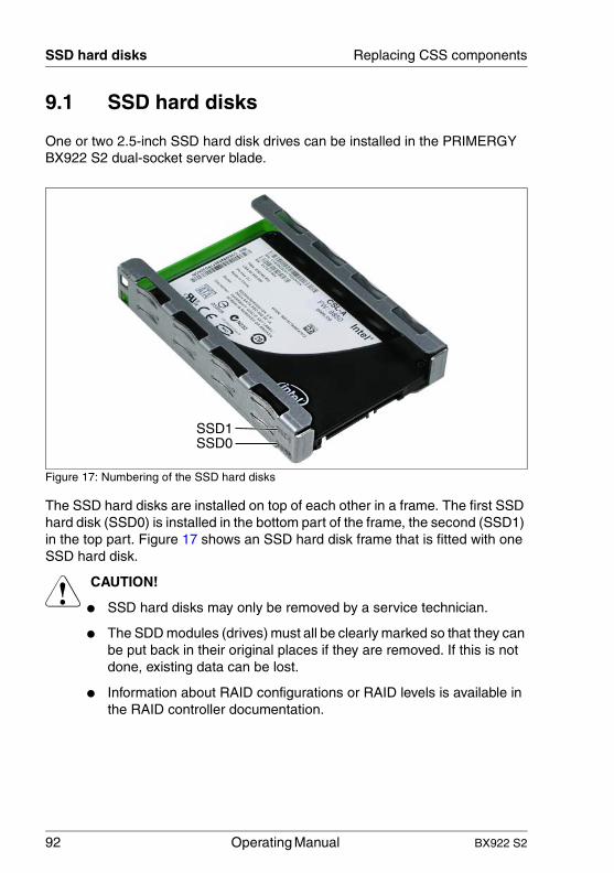
92 Operating Manual BX922 S2
SSD hard disks Replacing CSS components
© c
ogni
tas.
Ges
ells
chft
für
Tech
nik-
Dok
ume
ntat
ion
mb
H 2
010
P
fad:
C:\P
rogr
am
me\
FC
T\ti
m_a
pp\ti
m_l
oca
l\wor
k\W
ALT
ER
\OB
J_D
OK
U-4
966-
001
.fm
9.1 SSD hard disks
One or two 2.5-inch SSD hard disk drives can be installed in the PRIMERGY BX922 S2 dual-socket server blade.
Figure 17: Numbering of the SSD hard disks
The SSD hard disks are installed on top of each other in a frame. The first SSD hard disk (SSD0) is installed in the bottom part of the frame, the second (SSD1) in the top part. Figure 17 shows an SSD hard disk frame that is fitted with one SSD hard disk.
V CAUTION!
● SSD hard disks may only be removed by a service technician.
● The SDD modules (drives) must all be clearly marked so that they can be put back in their original places if they are removed. If this is not done, existing data can be lost.
● Information about RAID configurations or RAID levels is available in the RAID controller documentation.
SSD1SSD0

BX922 S2 Operating Manual 93
Replacing CSS components SSD hard disks
Figure 18: 2.5-inch SSD hard disk with mounting frame and connection cable
1 SSD hard disk
2 Guide element for fixing the SSD hard disk in the mounting frame
3 Mounting frame
4 Connection for combination plugs (SATA and power supply)
5 Connection cable (SATA and power supply with combination plug)
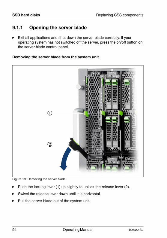
94 Operating Manual BX922 S2
SSD hard disks Replacing CSS components
© c
ogni
tas.
Ges
ells
chft
für
Tech
nik-
Dok
ume
ntat
ion
mb
H 2
010
P
fad:
C:\P
rogr
am
me\
FC
T\ti
m_a
pp\ti
m_l
oca
l\wor
k\W
ALT
ER
\OB
J_D
OK
U-4
966-
001
.fm
9.1.1 Opening the server blade
Ê Exit all applications and shut down the server blade correctly. If your operating system has not switched off the server, press the on/off button on the server blade control panel.
Removing the server blade from the system unit
Figure 19: Removing the server blade
Ê Push the locking lever (1) up slightly to unlock the release lever (2).
Ê Swivel the release lever down until it is horizontal.
Ê Pull the server blade out of the system unit.
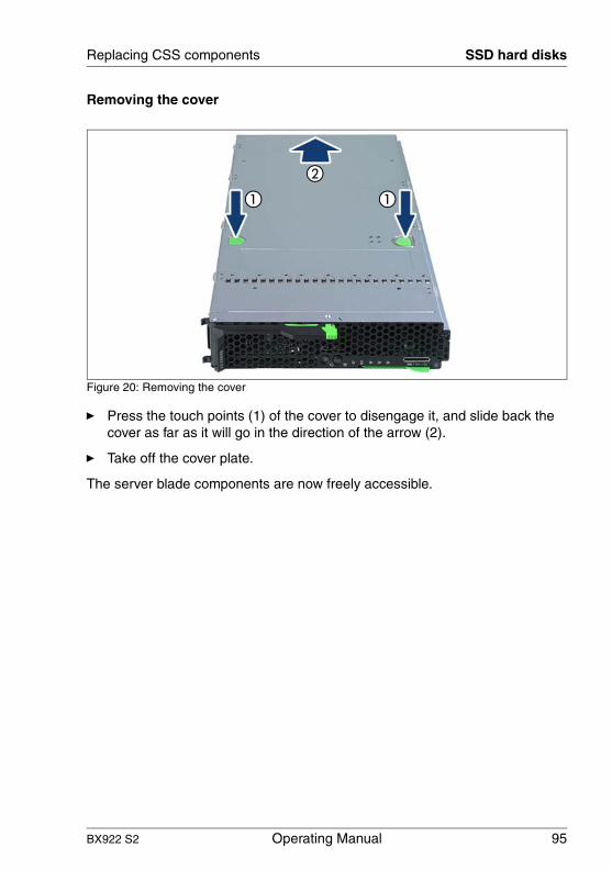
BX922 S2 Operating Manual 95
Replacing CSS components SSD hard disks
Removing the cover
Figure 20: Removing the cover
Ê Press the touch points (1) of the cover to disengage it, and slide back the cover as far as it will go in the direction of the arrow (2).
Ê Take off the cover plate.
The server blade components are now freely accessible.

96 Operating Manual BX922 S2
SSD hard disks Replacing CSS components
© c
ogni
tas.
Ges
ells
chft
für
Tech
nik-
Dok
ume
ntat
ion
mb
H 2
010
P
fad:
C:\P
rogr
am
me\
FC
T\ti
m_a
pp\ti
m_l
oca
l\wor
k\W
ALT
ER
\OB
J_D
OK
U-4
966-
001
.fm
9.1.2 Replacing the SSD hard disk
This section describes how to replace the SSD hard disk in bay SSD0. The SSD hard disk in bay SSD1 is replaced in the same way.
Removing an SSD hard disk
Figure 21: Disconnecting the connection cables of the SSD hard disk from the system board.
Ê Disconnect the SSD cables from the connectors on the system board.

BX922 S2 Operating Manual 97
Replacing CSS components SSD hard disks
Figure 22: Removing the SSD hard disk mounting frame.
Ê Press on the touch point (1) to release the SSD hard disk mounting frame and slide it as far as it will go in the direction of the arrow.
Ê Remove the mounting frame from the server blade housing.
Ê Disconnect the combination plug of the cable from the connector on the SSD hard disk.
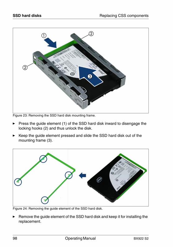
98 Operating Manual BX922 S2
SSD hard disks Replacing CSS components
© c
ogni
tas.
Ges
ells
chft
für
Tech
nik-
Dok
ume
ntat
ion
mb
H 2
010
P
fad:
C:\P
rogr
am
me\
FC
T\ti
m_a
pp\ti
m_l
oca
l\wor
k\W
ALT
ER
\OB
J_D
OK
U-4
966-
001
.fm
Figure 23: Removing the SSD hard disk mounting frame.
Ê Press the guide element (1) of the SSD hard disk inward to disengage the locking hooks (2) and thus unlock the disk.
Ê Keep the guide element pressed and slide the SSD hard disk out of the mounting frame (3).
Figure 24: Removing the guide element of the SSD hard disk.
Ê Remove the guide element of the SSD hard disk and keep it for installing the replacement.

BX922 S2 Operating Manual 99
Replacing CSS components SSD hard disks
Installing an SSD hard disk
Figure 25: Fitting the SSD hard disk into the guide element.
Ê Fit the SSD hard disk into the green plastic guide element. The 4 clips of the guide elements (see circles) must engage in the holes of the SSD hard disk.
Figure 26: Inserting the SSD hard disk in the mounting frame.
Ê Slide the SSD hard disk with the guide element into the mounting frame. Make sure that the clips of the guide element (see circles) engage in the openings of the mounting frame (1).

100 Operating Manual BX922 S2
SSD hard disks Replacing CSS components
© c
ogni
tas.
Ges
ells
chft
für
Tech
nik-
Dok
ume
ntat
ion
mb
H 2
010
P
fad:
C:\P
rogr
am
me\
FC
T\ti
m_a
pp\ti
m_l
oca
l\wor
k\W
ALT
ER
\OB
J_D
OK
U-4
966-
001
.fm
Figure 27: Connecting the cables to the SSD hard disk
Ê Connect the combination plug of the connection cables.
Figure 28: Base plate for mounting the SSD hard disk mounting frame
The SSD hard disk mounting frame is mounted onto a mounting plate that is located at the front of the server blade behind the control panel.
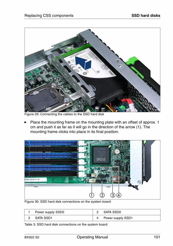
BX922 S2 Operating Manual 101
Replacing CSS components SSD hard disks
Figure 29: Connecting the cables to the SSD hard disk
Ê Place the mounting frame on the mounting plate with an offset of approx. 1 cm and push it as far as it will go in the direction of the arrow (1). The mounting frame clicks into place in its final position.
Figure 30: SSD hard disk connections on the system board
1 Power supply SSD0 2 SATA SSD0
3 SATA SSD1 4 Power supply SSD1
Table 3: SSD hard disk connections on the system board

102 Operating Manual BX922 S2
SSD hard disks Replacing CSS components
© c
ogni
tas.
Ges
ells
chft
für
Tech
nik-
Dok
ume
ntat
ion
mb
H 2
010
P
fad:
C:\P
rogr
am
me\
FC
T\ti
m_a
pp\ti
m_l
oca
l\wor
k\W
ALT
ER
\OB
J_D
OK
U-4
966-
001
.fm
Ê Connect the SATA cable and the power cable of the SSD hard disk to the connectors on the system board.
9.1.3 Closing the server blade
Figure 31: Closing the server blade
Ê Place the server blade cover on the housing about 1-2 cm from the frame so that it lies flush on both sides.
Ê Slide the cover forward in the direction of the arrow until it engages.
Ê Install the server blade in the system unit, see "Installing the Server Blade in the system unit" on page 36.

BX922 S2 Operating Manual 103
IndexAacclimatization time 35Advanced Video Redirection 16ambient conditions 21ASR&R 15availability 15AVR 16
BBIOS
security functions 83BIOS Setup 53
access 56Advanced menu, memory
configuration 66Advanced menu, Peripheral
Configuration 64Boot menu 80Exit menu 81operation 57
BIOS update 18
CCables
disconnecting 41cables
connecting 41CE marking 20, 31certification
product safety 21Class A Compliance Statement 32clean
keyboard 51mouse 51screen 51server 51
connectexternal devices 41
connectingcables 41
consumables 33
correcting faults 85CSS indicator 45, 46
Ddata changes 11data protection 83data security 15date, incorrect 87delivery note 36Disconnecting
cables 41disposal, devices 34Drive
"dead" 88drive
defective 89dummy module
install 36server blade 36
EECC 15Electrical data 20electromagnetic compatibility 20, 31electrostatic-sensitive devices
(ESD) 30EMC directive 20environment class 21environmental protection 33error
drifting display on monitor 87drive "dead" 88drive defective 89incorrect date 87incorrect time 87no display on monitor 87screen remains blank 85screen shows flickering
stripes 86server switches itself off 85system does not boot 87

104 Operating Manual BX922 S2
Index
© c
ogni
tas.
Ges
ells
chft
für
Tech
nik-
Dok
ume
ntat
ion
mb
H 2
010
P
fad:
C:\P
rogr
am
me\
FC
T\ti
m_a
pp\ti
m_l
oca
l\wor
k\W
ALT
ER
\OB
J_D
OK
U-4
967-
001
.fm
Error Correcting Code 15error message on screen 89ESD (electrostatic-sensitive
devices) 30expansion card 14external devices
connect 41
Ffault
drifting display on monitor 87drive defective 89incorrect date 87incorrect time 87no display on monitor 87screen remains blank 85screen shows flickering
stripes 86system does not boot 87
FCC statement 32flash EPROM 18
GGlobal Error indicator 45
Hhard disk drive
HDD module 92installing 92mounting frame 92
HDD moduleacclimatization time 35dummy module 92handling 92
IID button 44ID card
product name 36serial number 36
ID indicator 45indicators
CSS 45, 46Global Error 45
ID 45system error 45
information, additional 12install
dummy module 36installation steps for the server blade
overview 23installation steps, overview 23installing
hard disk drives 92Installing the operating system 50integrated Remote Management
Controller 16iRMC S2 16
Llabels 34laser information 30light emitting diode (LED) 30lithium battery 28Low Voltage Directive 20, 31
Mmeaning of the symbols 19mezzanine card 14monitor
display drifts 87no display 87
Nnotational conventions 19
OOn/Off button 44onboard SATA controller 48overload 17overview
installation steps for the server blade 23
Ppackaging 33, 36PCI SAS controller, configuring 50PCIe Gen2 slot 14

BX922 S2 Operating Manual 105
Index
PDA 15, 17ports
USB 15power-on indicator 44product name 36property protection 83
RRAID controller is not configured for
this drive 89recycling devices 34regulations and standards 20Remote Storage 16return of devices 34
SSafety instructions 25safety standards 20saving energy 33Screen
flickering 86screen
error message 89remains blank 85shows flickering stripes 86
security functions 11setup password 83system password 83unauthorized access 83
serial number 36Server
electrical data 20safety standards 20transportation 32
serverambient conditions 21configuration 17correcting faults 85data protection 83dimensions 21product name 36property protection 83serial number 36switches itself off (error) 85
technical data 20troubleshooting 85unpacking 36ventilation clearance 21weight 21
server bladeclose 102connection panel 43control panel 43controls 43dummy module 36hard disk drives 92indicators 43remove cover 95removing from system unit 94
server management 17ServerView Installation Manager 17,
49ServerView Operations Manager 17
supported functions 17service LAN connector 16setup password 83slot, expansion card 14Solid State Disk 92SSD hard disk 93
connect 101connection cable 93install 99mounting frame 93plastic guide 93remove 96
SSD hard disks 92switch-off time
defining 47switch-on time
defining 47switching off
system 47switching on
system 47system
switching off 47switching on 47
system board, features 14

106 Operating Manual BX922 S2
Index
© c
ogni
tas.
Ges
ells
chft
für
Tech
nik-
Dok
ume
ntat
ion
mb
H 2
010
P
fad:
C:\P
rogr
am
me\
FC
T\ti
m_a
pp\ti
m_l
oca
l\wor
k\W
ALT
ER
\OB
J_D
OK
U-4
967-
001
.fm
system does not boot 87system password 83
Ttarget group 11Technical data 20technical data 20time, incorrect 87tips 85TPM 14transport damage 36troubleshooting 85troubleshooting, server 85Trusted Platform Module 14
UUFM 15unauthorized access 83unpacking, server 36USB port 15
Vventilation clearance 21
Wweight 21