Primary Standards fB hh Sfor Brachytherapy Sources€¦ · Primary Standards fB hh Sfor...
69
Primary Standards f B h h S for Brachytherapy Sources Michael G. Mitch, Ph.D. Christopher G. Soares, Ph.D. Ph i Lb t N ti lI tit t f St d d dT h l (NIST) Physics Laboratory, National Institute of Standards and T echnology (NIST)
Transcript of Primary Standards fB hh Sfor Brachytherapy Sources€¦ · Primary Standards fB hh Sfor...

Primary Standards
f B h h Sfor Brachytherapy Sources
Michael G. Mitch, Ph.D.
Christopher G. Soares, Ph.D.
Ph i L b t N ti l I tit t f St d d d T h l (NIST)Physics Laboratory, National Institute of Standards and Technology (NIST)

Photon-emitting sourcesg
L 50 k V Hi hLow-energy < 50 keV < High-energy
LDR HDR LDR HDR
SK SK SK SK, Dw
WAFAC FAC Cavity Cavity, Calorimeter

Sources are Calibrated in Terms of Air-Kerma Strength (U)
dSource Air VolumeSource Air VolumeVacuum
SK = K (d) d 2
1 U = 1 Gy m2 h-1
.
• Air-kerma strength is the product of the air-kerma rate, in vacuo and due
1 U 1 Gy m h
to photons of energy greater than , at distance d and the square of this distance.
Ai k b d b l l i h f i h b• Air kerma can be measured absolutely with a free-air chamber

Low-energy, LDR seeds 20 keV < E < 35 keV
Ag wire, end weldsAg wire, end welds
Ag spheres, end welds
Resin spheres, Au-Cu markers
W wire, double wall

• Since 1999, NIST has calibrated over 900 sources
• 40 designs from 18 manufacturers
3 di lid 125I 103Pd 131C• 3 radionuclides: 125I, 103Pd, 131Cs

Primary Standard for Low-Energy X Rays (20 kV to 100 kV):
Ritz Free-Air Chamber (125I seeds, 1985)
V
Source(4 to 6 125I seeds)
Electrometer
(4 to 6 125I seeds)
Collecting Volume = 440 cm3
Active Volume = 5.5 cm3
Collecting/Active Volumes = 80

Ritz Free-Air Chamber Wide-Angle Free-Air Chamber(WAFAC, 125I, 103Pd, 131Cs, 1999) ( , , , , )
V
Electrometer
ElectrometerV/ 2
V
Collecting Volume = 440 cm3 Collecting Volume = 2500 cm3
3Active Volume = 5.5 cm3
Collecting/Active Volumes = 80
Active Volume = 715 cm3
Collecting/Active Volumes = 3.5

160 mm Al Center
Wide-Angle Free-Air Chamber (WAFAC)
Al Filt
Electrode
Al Filter
W Electrometer
Rotating Source
Aperture
V/ 2V = - 1674 V
Aluminized Mylar Electrodes

43 mm Al Center
Wide-Angle Free-Air Chamber (WAFAC)
Al Filt
Electrode
Al Filter
W Electrometer
Rotating Source
Aperture
V/ 2V = - 450 V
Aluminized Mylar Electrodes

Air-Kerma Strength from WAFAC Measurements
jj
iidetdr
effairairK QKKQKMKK
Vd
eWdQKS )(),()()(
22
125I
Net current, sI 0.06
Value Type A (%) Type B (%)
Net current, s 0.06),(det QKM
I
eW / 33.97 J / C - 0.15Air density, ρair 1.196 mg / cm3 - 0.03Aperture distance, d - 0.24Effective chamber volume, Veff 0.11 0.01Decay correction, K1 T1/2 = 59.43 d - 0.02Recombination < 1 004 0 05)(KK Recombination, < 1.004 - 0.05Attenuation in filter, K3(Q) 1.0295 - 0.61Air attenuation in WAFAC, K4(Q) 1.0042 - 0.08Source-aperture attenuation, K5(Q) 1.0125 - 0.24Inverse-square correction, K6 1.0089 - 0.01Humidity, K7(Q) 0.9982 - 0.07
)(KKdr
Humidity, K7(Q) 0.9982 0.07In-chamber photon scatter, K8(Q) 0.9966 - 0.07Source-holder scatter, K9 0.9985 - 0.05Electron loss, K10 1.0 - 0.05Aperture penetration, K11(Q) 0.9999 - 0.02External photon scatter, K12(Q) 1.0 - 0.17
Combined standard uncertainty, uc (s2 + 0.7622)1/2
Expanded uncertainty, V 2uc

Original and Automated WAFACs
AutomatedHPGe
SpectrometerAl filterwheel
OriginalWAFAC
WAFACseed
WAFAC
seed

Reference air kerma of low-energy photon-emitting LDR sources
• GROVEX (Grossvolumen Extrapolationskammer) – PTB
• VAFAC (Variable-Aperture Free-Air Chamber) – University of Wisconsin
• 3 L thin-walled cavity chamber radionuclide calibrator – NPL
• Torus free-air chamber – LNHB

Characterization Measurements Following WAFAC Calibration:
1. rotational anisotropy (WAFAC)
2 x-ray spectrometry on transverse axis of seed2. x ray spectrometry on transverse axis of seed
3. well-ionization chamber response relative to WAFAC (I / SK)
4. exposure of radiochromic film (contact geometry)
5 l t t ( )5. angular x-ray spectrometry (A)

Quality Assurance for WAFAC Measurements:
1. 241Am check source
2 x-ray spectrometry on transverse axis of seed2. x ray spectrometry on transverse axis of seed
3. well-ionization chamber response relative to WAFAC (I / SK)

1.06
263 seeds, 2003-2005: Range = (7 ± 5) %
Rotational Anisotropy (WAFAC)
1.00
1.02
1.04
ve C
urre
nt
8 %
0 94
0.96
0.98
Rel
ativ
z
0.94-20 20 60 100 140 180 220 260 300 340 380
Rotation Angle (degrees)
1.06 x
y
1.02
1.04
Cur
rent
2 %
x
= 0, 45, 90…360o
0.96
0.98
1.00
Rel
ativ
e C 2 %
0.94-20 20 60 100 140 180 220 260 300 340 380
Rotation Angle (degrees)

X-ray spectrometry of 103Pd and 131Cs seeds
100000
120000
Rh K
103Pd: EC, T1/2 = 16.99 d
60000
80000
100000
Cou
nts
Rh KRh K 20.1 keVRh K 22.7 keV, 23.2 keV
20000
40000
C Rh K
05 10 15 20 25 30 35 40
Energy (keV)
X K
150000
200000
nts
131Cs: EC, T1/2 = 9.69 d
Xe K
50000
100000Cou
n
Xe K 29.4 keV, 29.8 keVXe K 33.6 keV, 34.4 keV
Xe K
05 10 15 20 25 30 35 40
Energy (keV)

X-ray spectrometry of 125I seeds
100000
120000
Te K
125I: EC, T1/2 = 59.43 d
T K 27 2 k V 27 5 k V60000
80000
Cou
nts
Te K 27.2 keV, 27.5 keVTe K 31.0 keV, 31.7 keV125I 35.5 keV
20000
40000
C
Te K
125I
100000
05 10 15 20 25 30 35 40
Energy (keV)
T K
Ag K 22 1 keV 60000
80000
100000
nts
125I (Ag)
Te K
Ag K 22.1 keVAg K 24.9 keV, 25.4 keVTe K 27.2 keV, 27.5 keVTe K 31.0 keV, 31.7 keV 20000
40000
Cou
n
Te K
125I Ag K
Ag K125I 35.5 keV
05 10 15 20 25 30 35 40
Energy (keV)
Ag K
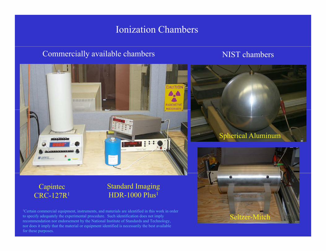
Ionization Chambers
NIST chambersCommercially available chambers
Spherical Aluminum
CapintecCRC-127R1
Standard ImagingHDR-1000 Plus1
Seltzer-Mitch1Certain commercial equipment, instruments, and materials are identified in this work in orderto specify adequately the experimental procedure. Such identification does not imply recommendation nor endorsement by the National Institute of Standards and Technology, nor does it imply that the material or equipment identified is necessarily the best available for these purposes.

Well Chamber Measurement Geometry
• Seed placed in end of catheter
• Centering jig for catheter
• Optimum vertical positioning
• Orientational effects:
1) up/down1) up/down
2) “points-of-compass”

Well Chamber Response Coefficients for 22 Seed Models
5.3
5.8
I (pA)S (U)
4.3
4.8
no Ag
131CsSK (U)
3.8
I / S
K (p
A /
U)
12
Ag wires
no Ag
2.8
3.3
103Pd
125IAg spheresAg spheres
1.8
2.3

Control Chart, I / SK, 125I seed “D”
4 45
4.50
4.35
4.40
4.45
4.25
4.30
I / S
K (p
A /
U)
4.10
4.15
4.20
I
4.05Apr05 Aug05 Jul06 Feb07 Nov07

I / SK vs. Ag K / , 125I seed “D”
4 45
4.50
4 30
4.35
4.40
4.45/ U
)
4.20
4.25
4.30
I / S
K (p
A /
4.05
4.10
4.15
2 5 2 7 2 9 3 1 3 3 3 5 3 7 3 92.5 2.7 2.9 3.1 3.3 3.5 3.7 3.9
Ag K /

Radiochromic film imaging in contact exposure geometry
MD-55-2
0 35
0.45
D
Profile Scan
PeC Microdensitometer0.15
0.25
0.35
0 2 4 6 8 10
OD
0 2 4 6 8 10
X Position (mm)

Air Anisotropy Ratio = A
HPGespectrometer
( = 0 )seed
z
( = 0, )
( = /2, 3/2) x
y
177 cm Seed rotates in the x-y plane about the z axis
)2/3()2/()()0(
specspec
specspecA
KKKK
EK
en
i = photon fluence rate.
ii
ii EK
en
spec Ei = photon energy(en / )i = mass energy-absorption coefficient

Measurement Geometry for WAFAC, HPGe Spectrometer
seed
WAFAC / 2 ~ 8o
HPGe / 2 ~ 0.2o

Measurement Geometry for Well Chamber
WAFAC / 2 ~ 8o
Well Chamber~ 4
HPGe / 2 ~ 0.2o

Seed with Highly Uniform Emission (A ~ 1)
WAFAC / 2 ~ 8o
Well Chamber~ 4

Seed with Highly Directional Emission (A ~ 0)
LOWERSK
I
WAFAC / 2 ~ 8o
Well Chamber~ 4
more directional less emission “missed” by the WAFACthat is detected by the well chamber

2 25
103Pd seeds with sphere or pellet design
2.20
2.25Eav = 20.7 keV
SK
I
2.15Model
“A”Model
“B”
Model“C”
2.05
2.10
/ SK (
pA /
U)
2.00
2.05I
Model“D”
1.95
D
1.90

2 25
103Pd seeds with sphere or pellet design
2.20
2.25Eav = 20.7 keV
SK
I
2.15Model
“A”Model
“B”
Model“C”
2.05
2.10
/ SK (
pA /
U)
0.33 0.24 0.49
2.00
2.05I
A Model“D”
1.95
0.06
D
1.90

125I seed Model “E”I
4.40Eav = 27.3 keV
SK
I
4.30
4.35
U)
av
4.20
4.25
I / S
K (p
A /
U
- 2.6 %
Nov03Sep02Feb02
4 05
4.10
4.15Sep02
May04
Feb02
4.05y

125I seed Model “E”
A
0.16 Eav = 27.3 keV
0.13
0.14
Nov03Sep02Feb02
av
0.10
0.11
A - 38 %
Nov03Sep02Feb02
0 05
0.07
0.08
May04
0.05

Effects of Seed Geometry and Nuclide on A
0.9
1.0
0.7
0.8
0.4
0.5
0.6
A
0 1
0.2
0.3
0.0
0.1

Effects of Seed Geometry and Nuclide on A
1 Same Design for 125I and 103Pd Models No End Welds
0.9
1.0
1. Same Design for 125I and 103Pd Models, No End Welds
0.7
0.8
0.4
0.5
0.6
A
125I 103Pd
0 1
0.2
0.3
0.0
0.1

Effects of Seed Geometry and Nuclide on A
2 Same Design for 125I and 103Pd Models With End Welds
0.9
1.0
2. Same Design for 125I and 103Pd Models, With End Welds
0.7
0.8
0.4
0.5
0.6
A
0 1
0.2
0.3 125I
103Pd
0.0
0.1

Effects of Seed Geometry and Nuclide on A
3 125I Models: Uniform Encapsulation vs End Welds
0.9
1.0
3. 125I Models: Uniform Encapsulation vs. End Welds (“radiotransparent” substrate)
UE
0.7
0.8UE
0.4
0.5
0.6
A
0 1
0.2
0.3 EW
0.0
0.1

Effects of Seed Geometry and Nuclide on A
4 125I Models w/ Ag: Wire vs Sphere Substrates
0.9
1.0
4. 125I Models w/ Ag: Wire vs. Sphere Substrates
0.7
0.8
0.4
0.5
0.6
A
0 1
0.2
0.3
W0.0
0.1 W S

Well Chamber Response Coefficients for 22 Seed Models
5.3
5.8
I (pA)
4.8
5.3
131CsSK (U)
3.8
4.3
SK (p
A /
U)
Ag wires
no Ag
2.8
3.3
I /
103Pd
125IAg spheresAg spheres
1.8
2.3
103Pd

Photon-emitting sourcesg
L 50 k V Hi hLow-energy < 50 keV < High-energy
LDR HDR LDR HDR
SK SK SK SK, Dw
WAFAC FAC Cavity Cavity, Calorimeter

Primary Standard for Low-Energy X Rays (10 kV to 60 kV):
Lamperti Free-Air Chamber
V
HPGe
Miniature x-ray tube source El t ttube source
40 kV to 50 kVElectrometer

Primary Standard for Mammography X Rays (≤ 50 kV):
Attix Free-Air Chamber (NIST, University of Wisconsin)
Electrometer
Miniature x-ray
V
Miniature x ray tube source
40 kV to 50 kV

Photon-emitting sourcesg
L 50 k V Hi hLow-energy < 50 keV < High-energy
LDR HDR LDR HDR
SK SK SK SK, Dw
WAFAC FAC Cavity Cavity, Calorimeter

Primary Standard for Gamma Rays from 137Cs and 192Ir
1. Graphite-walled Cavity Chambers
)/()/(12 LdW )()(),()()/()/(
)/()/(
11)(
22 QKQKKQKMKK
LL
gVd
eWdQKS hwallstemdetdr
air
gr
gren
airen
airairK
137Cs1
1 cm31 source
192Ir
50 cm350 sources

Primary Standard for Gamma Rays from 137Cs and 192Ir
2. Spherical Aluminum Cavity and Re-entrant Chambers
2800 cm3137CsUS
WSUS ISS2800 cm3137CsWorking standard (WS)
orUnknown source (US)
WSKK ISS
U ow sou ce (US)
192Ir
3400 cm3
50
1ii
KUSUSK
I
SIS
226Ra sourceT1/2 = 1600 y

Photon-emitting sourcesg
L 50 k V Hi hLow-energy < 50 keV < High-energy
LDR HDR LDR HDR
SK SK SK SK, Dw
WAFAC FAC Cavity Cavity, Calorimeter
Primary Standard for Gamma Rays from HDR 192Ir
Graphite-walled Cavity Chamber, Kair
N i l Ph i l L b (NPL UK)• National Physical Laboratory (NPL, UK)• Laboratoire National Henri Becquerel (LNHB, France)• Physikalisch Technische Bundesanstalt (PTB, Germany)• Nederlands Meetinstitut (NMi Netherlands)• Nederlands Meetinstitut (NMi, Netherlands)• Bhabha Atomic Research Centre (BARC, India)
Water Calorimeter, Dw
• McGill University (Sarfehnia, Stewart, and Seuntjens)

Secondary Standard for Gamma Rays from HDR 192Ir
Goetsch “Seven Distance” Technique (1991), AAPM ADCLs
)(2)()( 250250
QKNQKNQK
N Irwall
CsK
Cswall
MK
MwallIr
K
NIST traceability is achieved through NKM250 and NK
Cs (cavity chamber)

Secondary Standard for Gamma Rays from HDR 192Ir
Goetsch “Seven Distance” Technique (1991), AAPM ADCLs
)(2)()( 250250
QKNQKNQK
N Irwall
CsK
Cswall
MK
MwallIr
K
NIST traceability is achieved through NKM250 and NK
Cs (cavity chamber)
“K-weighted Average” Technique, Mainegra-Hing and Rogers (2006)
Ei
KiIrair
Eiair
IrK NK
KN
11
2
111 250
CsK
MK
IrK
NNN192Ir ~ M250 + 137Cs
KairM250 = Kair
Cs

Secondary Standard for Gamma Rays from HDR 192Ir
Accounting for Scattering
1. Goetsch “Seven Distance” Technique

Secondary Standard for Gamma Rays from HDR 192Ir
Accounting for Scattering
1. Goetsch “Seven Distance” Technique

Secondary Standard for Gamma Rays from HDR 192Ir
Accounting for Scattering
1. Goetsch “Seven Distance” Technique
]),([)( scatdetIrKair MQKMNQK
2))(( cdQKS airK

Secondary Standard for Gamma Rays from HDR 192Ir
Accounting for Scattering
1. Goetsch “Seven Distance” Technique
]),([)( scatdetIrKair MQKMNQK
2))(( cdQKS airK
2. Shadow Shield Technique
),( QKM det

Secondary Standard for Gamma Rays from HDR 192Ir
Accounting for Scattering
1. Goetsch “Seven Distance” Technique
]),([)( scatdetIrKair MQKMNQK
2))(( cdQKS airK
2. Shadow Shield Technique
scatM

What about absorbed dose?
• Dose rate is typically measured using thermoluminescent dosimeters (TLDs)placed in solid, water-equivalent phantoms at various distances from a seed
• The dose rate at a reference point (1 cm from the seed on the trans erse a is) is• The dose rate at a reference point (1 cm from the seed on the transverse axis) is related to the NIST air-kerma strength standard, SK, through a dose-rate constant,
• Uncertainties on a TLD dose rate measurement at 1 cm are typically 4 % (k = 1)Uncertainties on a TLD dose rate measurement at 1 cm are typically 4 % (k 1), SK uncertainties are typically 1 % (k = 1), so uncertainty on is about 8 % (k = 2)
Step 1 Step 2
TLD
. =
D(r0, 0)
1 cm
SK
cGy h-1 U-1
SK measurement D(r0, 0) measurement. cGy h U

TG-43 Formalism
KSrD ),( 00
),()(),(
),(),(
00
rFrgrGrG
SrD LL
LK
Dose rate in water
)(rG 122 )4/()0( LrrG
Geometry Function
D )(
Dose rate constant (NIST-traceable SK)
sin
),(Lr
rGL )4/()0,( LrrGL
Radial Dose Function 2D Anisotropy Function1KS
rD ),( 00
),(),(
),(),(
)(0
00
00
0
rGrG
rDrD
rgX
XX
Radial Dose Function
),(),(
),(),(),( 0
0
rGrG
rDrDrF
L
L
2D Anisotropy Functionr0 = 1 cm0 = / 2

Beta-emitting sources
Dw
.
Extrapolation Chamber
• Ophthalmic applicators
1. Planar (90Sr/Y)
2 Conca e (106R /Rh)2. Concave (106Ru/Rh)
• IVB seed and line sources (90Sr/Y 32P)IVB seed and line sources ( Sr/Y, P)

Primary Standard for Beta Brachytherapy Sources
Extrapolation Chamber
kMkQSAe
WQD deteffair
0aw,w )('
dd)(1)(
slope of current vs. air gap
max
0 wcol,w d/)(
E
E ESQS
slope of current vs. air gap
max
0 acol,w
aw,d/
)( E
E ESQS
Bragg-Gray stopping power ratio

Extrapolation Chamber Schematic
Electrometer
Collectingelectrode
Insulatinggap
79.54 pA
gap
Water-equivalent plasticHigh-voltagel t d / i d
Air gap=0.40 mm
electrode/window
Source
rent
, pA
Ionization
Air gap, mm
Cur
r

Extrapolation Chamber Schematic
Electrometer
Collectingelectrode
Insulatinggap
69.73 pA
electrodegap
Water-equivalent plasticHigh-voltagel t d / i d
Air gap=0.35 mm
electrode/window
Source
rent
, pA
Ionization
Air gap, mm
Cur
r

Extrapolation Chamber Schematic
Electrometer
Collectingl t d
Insulating
59.82 pA
electrodegap
Water-equivalent plasticHigh-voltagel t d / i d
Air gap=0.30 mm
electrode/window
Source
rent
, pA
Ionization Cur
r
Air gap, mm

Extrapolation Chamber Schematic
Electrometer
CollectingInsulating
49.85 pA
gelectrode
Insulatinggap
Water-equivalent plasticHigh-voltagel t d / i d
Air gap=0.25 mm
electrode/window
Source
rent
, pA
Ionization Cur
r
Air gap, mm

Extrapolation Chamber Schematic
Electrometer
CollectingInsulating
39.89 pA
Collectingelectrode
Insulatinggap
Water-equivalent plasticHigh-voltagel t d / i d
Air gap=0.20 mm
electrode/window
Source
rent
, pA
Ionization Cur
r
Air gap, mm

Extrapolation Chamber Schematic
Electrometer
C ll ti
29.92 pA
Collectingelectrode
Insulatinggap
Water-equivalent plasticHigh-voltagel t d / i d
Air gap=0.15 mm
electrode/window
Source
rent
, pA
Ionization Cur
r
Air gap, mm

Extrapolation Chamber Schematic
Electrometer
19.95 pA
Collectingelectrode
Insulatinggap
Water-equivalent plasticHigh-voltagel t d / i d
Air gap=0.10 mm
electrode/window
Source
rent
, pA
Ionization Cur
r
Air gap, mm

Extrapolation Chamber Schematic
Electrometer
9.99 pA
Collectingelectrode
Insulatinggap
Water-equivalent plasticHigh-voltagel t d / i d
Air gap=0.05 mm
electrode/window
Source
rent
, pA
Ionization Cur
r
Air gap, mm

TG-60, TG-149 Formalism
KSrD ),( 00
)()(),()()( FrGDD L
Dose rate in water
)(rG 122 )4/()0( LrrG
Geometry Function
),()(),(
),(),(),(00
00
rFrgrG
rDrD LL
L
sin),(
LrrGL )4/()0,( LrrGL
Radial Dose Function 2D Anisotropy FunctionNIST-traceable D(r0, 0)
),(),(
),(),(
)(0
00
00
0
rGrG
rDrD
rgX
XX
Radial Dose Function
),(),(
),(),(),( 0
0
rGrG
rDrDrF
L
L
2D Anisotropy Functionr0 = 2 mm0 = / 2

Measurement Traceability for Brachytherapy Sources
sourcessourcesSK , Dw
.
Manufacturersecondary standardADCL
verification forwell-ionization
chamberssources
verification fortreatment planning
.Clinic SK
Clinic , DwClinic

Clinical Brachytherapy Source Measurements
W ll i i i h b lib d b ADCLWell-ionization chambers, calibrated by an ADCL
Photon-emitting sources Beta-emitting sources
ADCL
KClinicClinicK I
SIS
ADCL
wClinicClinicw I
DID
+ radiochromic film

Summary
• Air-kerma-strength standards are currently used for all photon-emittingbrachytherapy sources, realized by free-air and cavity ionization chambersbrachytherapy sources, realized by free air and cavity ionization chambers
• Absorbed-dose-to-water standards are used for all beta-emittingbrachytherapy sources, realized by extrapolation ionization chambersy py , y p
• Brachytherapy standards are transferred from NIST and the ADCLs to clinics using well-ionization chambers (radiochromic film for planarbeta-emitting sources)
• Absorbed-dose-to-water measurement methods for high-energy, HDR h t itti b h th tl d d l tphoton-emitting brachytherapy sources are currently under development
(water calorimetry)