Primary Breakup Model Considering Spray Core … – Europe 2010, 23rd Annual Conference on Liquid...
9
ILASS – Europe 2010, 23rd Annual Conference on Liquid Atomization and Spray Systems, Brno, Czech Republic, September 2010 Primary Breakup Model Considering Spray Core Development Fabian Fischer *1 , B. Heine 1 and C. Tropea 2 1 Corporate Research, Robert Bosch GmbH, D-70839 Gerlingen 2 Institute of Fluid Mechanics and Aerodynamics, Center of Smart Interfaces, Technische Universitaet Darmstadt, D-64287 Darmstadt Abstract In this paper a new model for Primary Breakup in the Euler-Lagrange framework will be presented. It features the consideration of nozzle specific local flow features and a detailed prediction of the development of the very dense part of the spray. The latter is achieved by means of a sub-model for the spray core, thus avoiding some of the well-known shortcomings of an Euler-Lagrange approach in the near-nozzle region. The model was success- fully validated against in-house experimental data by comparing density, droplet sizes and data rates at various downstream positions of the spray. Introduction In order to effectively reduce pollutant emissions in direct injection diesel and gasoline engines, an accurate simulation of the internal combustion process is needed. This can only be achieved if reliable predictions of the spray characteristics and the resulting fuel mixture formation are available. As it is widely accepted that spray characteristics are strongly affected by the internal nozzle flow, Primary Breakup models that employ this nozzle flow information are essential. While several Primary Breakup models in the Euler-Lagrange framework exist that take into account nozzle specific flow features, such as turbulence or cavitation [1,2], only a few are able to also capture the spatial effects of the local flow physics [3,4,5,6], some relying primarily on the local distribution of cavitation [7]. Furthermore, all these models suffer from a poor prediction of the behavior and development of the very dense part of the spray immediately downstream of the nozzle, in contrast to some alternative models [8] in the computationally more expensive Euler-Euler framework. In this paper a new model for Primary Breakup in the Euler-Lagrange framework considering nozzle specific local flow features and the development of the very dense part of the spray will be presented. This new model is validated against in-house experimental data. Overview of the Model The model comprises the injection of primary blobs from which secondary droplets will subsequently break up according to the breakup mechanism described by Wu et al. [9], Faeth et al. [10] and Sallam et al. [11], pro- viding the droplet sizes of released droplets as well as the breakup rate. In order to capture the effects of nozzle specific local flow features on this breakup, temporally resolved nozzle flow simulations have to be performed beforehand. The resulting flow field, including the turbulence data, is then mapped onto an auxiliary polar grid for each injected primary blob, thus providing local flow properties as well as their temporal variation, which are utilized in determining the breakup process. A similar approach has been used in previous models [3,5,6]. While the dispersed droplet approach used in these models yields good results for diluted sprays, it fails to reproduce correct spray behavior in the vicinity of the nozzle, where coherent liquid structures are present. Pri- mary blobs and the subsequent secondary droplets cannot account for the complex interactions of the turbulent liquid jet with the surrounding gas phase. To overcome this drawback a sub-model for the development of the spray near to the nozzle is applied. Using the mapped nozzle flow data on the auxiliary polar grids a one-fluid approach, as was originally proposed by Vallet and Borghi [12], is employed to describe the initial dispersion of the liquid. The position of primary blobs as well as the initial position and velocity of released secondary drop- lets are then chosen in such a way, that the flow field calculated in this process is reproduced by the dispersed droplet phase. Since the time step and spatial resolution used within this sub-model are independent of grid size and the time step used in the internal combustion calculation, this method allows for very accurate predictions of the spray core development without increasing overall calculation time noticeably. Figure 1 schematically depicts the presented modeling approach, which will be described in more detail in the following section. * Corresponding author: [email protected] 1
-
Upload
truongtruc -
Category
Documents
-
view
215 -
download
1
Transcript of Primary Breakup Model Considering Spray Core … – Europe 2010, 23rd Annual Conference on Liquid...

ILASS – Europe 2010, 23rd Annual Conference on Liquid Atomization and Spray Systems, Brno, Czech Republic, September 2010
Primary Breakup Model Considering Spray Core Development
Fabian Fischer*1, B. Heine1 and C. Tropea2 1Corporate Research, Robert Bosch GmbH, D-70839 Gerlingen
2Institute of Fluid Mechanics and Aerodynamics, Center of Smart Interfaces,
Technische Universitaet Darmstadt, D-64287 Darmstadt
Abstract In this paper a new model for Primary Breakup in the Euler-Lagrange framework will be presented. It features the consideration of nozzle specific local flow features and a detailed prediction of the development of the very dense part of the spray. The latter is achieved by means of a sub-model for the spray core, thus avoiding some of the well-known shortcomings of an Euler-Lagrange approach in the near-nozzle region. The model was success-fully validated against in-house experimental data by comparing density, droplet sizes and data rates at various downstream positions of the spray.
Introduction In order to effectively reduce pollutant emissions in direct injection diesel and gasoline engines, an accurate
simulation of the internal combustion process is needed. This can only be achieved if reliable predictions of the spray characteristics and the resulting fuel mixture formation are available. As it is widely accepted that spray characteristics are strongly affected by the internal nozzle flow, Primary Breakup models that employ this nozzle flow information are essential. While several Primary Breakup models in the Euler-Lagrange framework exist that take into account nozzle specific flow features, such as turbulence or cavitation [1,2], only a few are able to also capture the spatial effects of the local flow physics [3,4,5,6], some relying primarily on the local distribution of cavitation [7]. Furthermore, all these models suffer from a poor prediction of the behavior and development of the very dense part of the spray immediately downstream of the nozzle, in contrast to some alternative models [8] in the computationally more expensive Euler-Euler framework. In this paper a new model for Primary Breakup in the Euler-Lagrange framework considering nozzle specific local flow features and the development of the very dense part of the spray will be presented. This new model is validated against in-house experimental data.
Overview of the Model The model comprises the injection of primary blobs from which secondary droplets will subsequently break
up according to the breakup mechanism described by Wu et al. [9], Faeth et al. [10] and Sallam et al. [11], pro-viding the droplet sizes of released droplets as well as the breakup rate. In order to capture the effects of nozzle specific local flow features on this breakup, temporally resolved nozzle flow simulations have to be performed beforehand. The resulting flow field, including the turbulence data, is then mapped onto an auxiliary polar grid for each injected primary blob, thus providing local flow properties as well as their temporal variation, which are utilized in determining the breakup process. A similar approach has been used in previous models [3,5,6].
While the dispersed droplet approach used in these models yields good results for diluted sprays, it fails to reproduce correct spray behavior in the vicinity of the nozzle, where coherent liquid structures are present. Pri-mary blobs and the subsequent secondary droplets cannot account for the complex interactions of the turbulent liquid jet with the surrounding gas phase. To overcome this drawback a sub-model for the development of the spray near to the nozzle is applied. Using the mapped nozzle flow data on the auxiliary polar grids a one-fluid approach, as was originally proposed by Vallet and Borghi [12], is employed to describe the initial dispersion of the liquid. The position of primary blobs as well as the initial position and velocity of released secondary drop-lets are then chosen in such a way, that the flow field calculated in this process is reproduced by the dispersed droplet phase. Since the time step and spatial resolution used within this sub-model are independent of grid size and the time step used in the internal combustion calculation, this method allows for very accurate predictions of the spray core development without increasing overall calculation time noticeably.
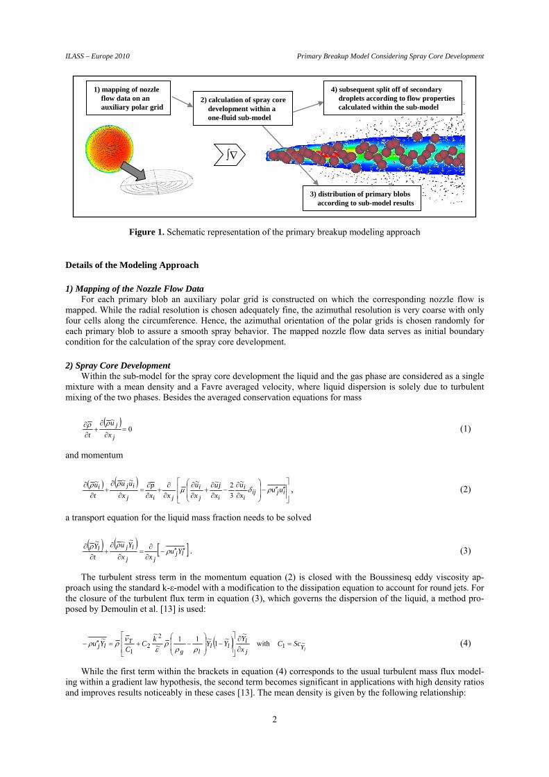
Figure 1 schematically depicts the presented modeling approach, which will be described in more detail in the following section.
* Corresponding author: [email protected]
1
ILASS – Europe 2010 Primary Breakup Model Considering Spray Core Development
1) mapping of nozzleflow data on anauxiliary polar grid
4) subsequent split off of secondarydroplets according to flow propertiescalculated within the sub-model
Figure 1. Schematic representation of the primary breakup modeling approach
Details of the Modeling Approach
1) Mapping of the Nozzle Flow Data For each primary blob an auxiliary polar grid is constructed on which the corresponding nozzle flow is
mapped. While the radial resolution is chosen adequately fine, the azimuthal resolution is very coarse with only four cells along the circumference. Hence, the azimuthal orientation of the polar grids is chosen randomly for each primary blob to assure a smooth spray behavior. The mapped nozzle flow data serves as initial boundary condition for the calculation of the spray core development.
2) Spray Core Development Within the sub-model for the spray core development the liquid and the gas phase are considered as a single
mixture with a mean density and a Favre averaged velocity, where liquid dispersion is solely due to turbulent mixing of the two phases. Besides the averaged conservation equations for mass
0
~
j
j
x
u
t
(1)
and momentum
ijiji
i
ij
i
jij
iji uux
u
x
ju
x
u
xx
p
x
uu
t
u
~
3
2~~~~~, (2)
a transport equation for the liquid mass fraction needs to be solved
ljjj
ljl Yuxx
Yu
t
Y
~~~. (3)
The turbulent stress term in the momentum equation (2) is closed with the Boussinesq eddy viscosity ap-proach using the standard k-ε-model with a modification to the dissipation equation to account for round jets. For the closure of the turbulent flux term in equation (3), which governs the dispersion of the liquid, a method pro-posed by Demoulin et al. [13] is used:
lY
j
lll
lg
Tlj ScC
x
YYY
kC
CYu ~1
2
21
with~
~1
~11~
~~
(4)
While the first term within the brackets in equation (4) corresponds to the usual turbulent mass flux model-ing within a gradient law hypothesis, the second term becomes significant in applications with high density ratios and improves results noticeably in these cases [13]. The mean density is given by the following relationship:
3) distribution of primary blobsaccording to sub-model results
2) calculation of spray coredevelopment within aone-fluid sub-model
2
ILASS – Europe 2010 Primary Breakup Model Considering Spray Core Development
g
l
l
l YY
~1
~1
(5)
The above equations are solved on the auxiliary polar grids for each primary blob. In order to facilitate the numerical treatment, allowing for a direct and uncoupled solution of the flow field development, the following assumptions are made:
a stationary injection process is considered constant pressure is assumed radial symmetry is assumed only the equation for the axial momentum is solved, deriving radial velocities solely from the con-
tinuity equation diffusive effects along the jet axis are neglected
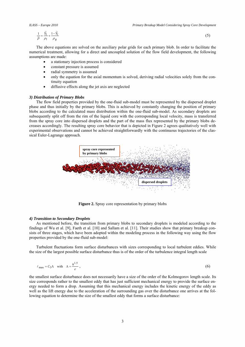
3) Distribution of Primary Blobs The flow field properties provided by the one-fluid sub-model must be represented by the dispersed droplet
phase and thus initially by the primary blobs. This is achieved by constantly changing the position of primary blobs according to the calculated mass distribution within the one-fluid sub-model. As secondary droplets are subsequently split off from the rim of the liquid core with the corresponding local velocity, mass is transferred from the spray core into dispersed droplets and the part of the mass flux represented by the primary blobs de-creases accordingly. The resulting spray core behavior that is depicted in Figure 2 agrees qualitatively well with experimental observations and cannot be achieved straightforwardly with the continuous trajectories of the clas-sical Euler-Lagrange approach.
spray core representedby primary blobs
dispersed droplets
Figure 2. Spray core representation by primary blobs
4) Transition to Secondary Droplets As mentioned before, the transition from primary blobs to secondary droplets is modeled according to the
findings of Wu et al. [9], Faeth et al. [10] and Sallam et al. [11]. Their studies show that primary breakup con-sists of three stages, which have been adopted within the modeling process in the following way using the flow properties provided by the one-fluid sub-model:
Turbulent fluctuations form surface disturbances with sizes corresponding to local turbulent eddies. While
the size of the largest possible surface disturbance thus is of the order of the turbulence integral length scale
5.1
3max withk
C , (6)
the smallest surface disturbance does not necessarily have a size of the order of the Kolmogorov length scale. Its size corresponds rather to the smallest eddy that has just sufficient mechanical energy to provide the surface en-ergy needed to form a drop. Assuming that this mechanical energy includes the kinetic energy of the eddy as well as the lift energy due to the acceleration of the surrounding gas over the disturbance one arrives at the fol-lowing equation to determine the size of the smallest eddy that forms a surface disturbance:
3
ILASS – Europe 2010 Primary Breakup Model Considering Spray Core Development
31
min25
24
min min
min
assuming
v
uCv
C
relgl
(7)
The formed surface disturbances grow with their characteristic velocity into ligaments and eventually reach their breakup length at which droplets are formed either by a Rayleigh type or an aerodynamic breakup. The characteristic time scales to reach this length are estimated in the following way:
relg
la
lR u
CC
7
3
6 and (8)
Equating both time scales the smaller one determines the breakup type of the ligament and the time until breakup is reached. The ligament then disintegrates into one or more droplets according to its breakup type. For the Rayleigh type breakup the resulting droplet size is assumed to be proportional to the ligament size
8Csd , (9)
and for aerodynamic breakup of the ligaments a correlation developed by Hsiang and Faeth [14] is used to de-termine the size of the resulting droplet.
To determine the rate at which ligaments evolve an efficiency factor is introduced. It is assumed that it in-
creases with the lifetime of the primary blob and is inversely proportional to the breakup time of a ligament with the size of the turbulence integral length scale:
aR
pb
Lrl
LL
tC
v
m
,min9,
(10)
Neglecting aerodynamic effects equation (10) equals qualitatively the one proposed by Sallam et al. [11] for the droplet split off rate. This approach is also consistent with the observations of Balewski et al. [15] that breakup is enhanced for increased turbulence intensities.
Results The presented primary breakup model has been implemented into the AVL Fire Code (v2008.2) using user
subroutines. For validation purposes spray calculations for two different nozzle geometries (V4 and V5) that were experimentally investigated by Balewski et al. [15] have been performed. For details on the applied ex-perimental measurement techniques, the nozzle geometries and the operating conditions the reader is referred to Balewski et al. [15].
Nozzle Flow Simulations As described earlier, the initial boundary conditions for the breakup model need to be supplied by nozzle
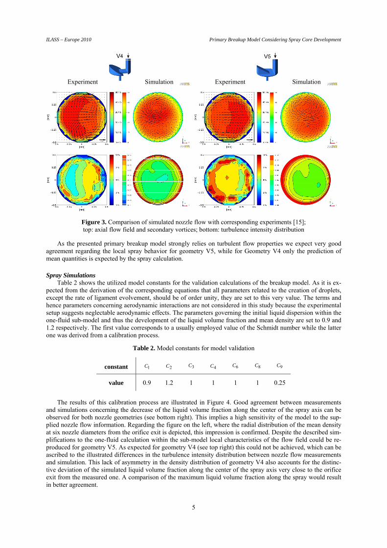
flow simulations. These simulations were carried out with the ANSYS CFX 11 solver using the BSL Reynolds Stress turbulence model. Figure 3 shows the resulting flow and turbulence fields at the nozzle outlet for the two different nozzle geometries in comparison to the experimental results.
While for geometry V5 a very good agreement between experiment and simulation is achieved, differences in the local distribution of the turbulence intensity between simulation and experiment for geometry V4 can be observed. In this case the experiment shows considerably higher turbulence intensities on the right hand side of the nozzle outlet and the simulation predicts only a slight increase of turbulence intensities on this side. Never-theless, referring to table 1 the mean turbulence intensity is reproduced well.
Table 1. Measured and simulated mean turbulence intensities at the nozzle outlet
V4 V5
Experiment 6.7 % 8.5 %
Simulation 6.5 % 8.7 %
4
ILASS – Europe 2010 Primary Breakup Model Considering Spray Core Development
Experiment Simulation Experiment Simulation
Figure 3. Comparison of simulated nozzle flow with corresponding experiments [15]; top: axial flow field and secondary vortices; bottom: turbulence intensity distribution
As the presented primary breakup model strongly relies on turbulent flow properties we expect very good agreement regarding the local spray behavior for geometry V5, while for Geometry V4 only the prediction of mean quantities is expected by the spray calculation.
Spray Simulations Table 2 shows the utilized model constants for the validation calculations of the breakup model. As it is ex-
pected from the derivation of the corresponding equations that all parameters related to the creation of droplets, except the rate of ligament evolvement, should be of order unity, they are set to this very value. The terms and hence parameters concerning aerodynamic interactions are not considered in this study because the experimental setup suggests neglectable aerodynamic effects. The parameters governing the initial liquid dispersion within the one-fluid sub-model and thus the development of the liquid volume fraction and mean density are set to 0.9 and 1.2 respectively. The first value corresponds to a usually employed value of the Schmidt number while the latter one was derived from a calibration process.
Table 2. Model constants for model validation
constant 1C 2C 3C 4C 6C 8C 9C
value 0.9 1.2 1 1 1 1 0.25
The results of this calibration process are illustrated in Figure 4. Good agreement between measurements
and simulations concerning the decrease of the liquid volume fraction along the center of the spray axis can be observed for both nozzle geometries (see bottom right). This implies a high sensitivity of the model to the sup-plied nozzle flow information. Regarding the figure on the left, where the radial distribution of the mean density at six nozzle diameters from the orifice exit is depicted, this impression is confirmed. Despite the described sim-plifications to the one-fluid calculation within the sub-model local characteristics of the flow field could be re-produced for geometry V5. As expected for geometry V4 (see top right) this could not be achieved, which can be ascribed to the illustrated differences in the turbulence intensity distribution between nozzle flow measurements and simulation. This lack of asymmetry in the density distribution of geometry V4 also accounts for the distinc-tive deviation of the simulated liquid volume fraction along the center of the spray axis very close to the orifice exit from the measured one. A comparison of the maximum liquid volume fraction along the spray would result in better agreement.
5

ILASS – Europe 2010 Primary Breakup Model Considering Spray Core Development
Experiment
Experiment Simulation
Simulation
Figure 4. Comparison of simulated and measured [16] liquid volume fractions and density distributions; left: mean density distribution for geometry V5 at six nozzle diameters (6mm) from the orifice exit; top: mean density distribution for geometry V4 at six nozzle diameters (6mm) from the orifice exit;
bottom right: development of the liquid volume fraction along the center of the spray axis
The displayed mean density distributions and its development in the vicinity of the nozzle are solely gov-erned by the one-fluid sub-model and independent of any breakup mechanisms. The actual breakup only affects the composition of the liquid in this region. This may be either of primary blobs that resemble the coherent liquid core or of ordinary parcels that represent detached droplets. The measured data rate of spherical droplets can serve as an indication of this composition. Low data rates are expected within the spray core, where non-spherical coherent structures are dominant in appearance. High data rates are expected at the positions where the transition of the spray core into detached droplets is completed. Further the data rate can be correlated to the strength of the primary breakup, as was pointed out by Balewski [16]. Likewise these assertions apply to the spray simulations when primary blobs are excluded from the data rate determination.
In Figure 5 the measured data rates for geometry V5 and the simulated normalized data rates of secondary droplets are compared. Regarding the figure it can be concluded that the utilized breakup mechanisms, especially the breakup rate, in conjunction with the one-fluid sub-model permit a very good prediction of the transition of the coherent liquid spray core into detached secondary droplets. The radial locations and axial development of the maximum data rate are well reproduced. Even the enhanced breakup on the left hand side, indicated by the higher data rate, is simulated correctly.
6

ILASS – Europe 2010 Primary Breakup Model Considering Spray Core Development
Figure 5. Comparison of measured [16] (left) and normalized simulated (right) data rates for geometry V5
As a further validation of the model the Sauter mean diameters resulting from the breakup mechanisms are compared with the experimentally measured ones. In Figure 6 this is depicted for geometry V5. Again good agreement between measurements and simulation could be achieved. The axial as well as the radial development of the droplet sizes is qualitatively and quantitatively well reproduced.
Figure 6. Comparison of measured [16] (left) and simulated (right) Sauter mean diameters for geometry V5
7

ILASS – Europe 2010 Primary Breakup Model Considering Spray Core Development
Summary and Conclusion A new primary breakup model considering the development of the spray core has been presented. Within
this model secondary droplet sizes and their axial development are determined according to a ligament breakup process, while the spray core development, and hence the radial locations of detachment and the initial droplet velocities, is calculated with a one-fluid approach within a separate sub-model.
Results obtained with the model for two different nozzle geometries were compared to experimental X-Ray and PDA data supplied by Balewski et al. [15,16] resulting in very good agreement. Comparisons were made concerning spray density as well as droplet sizes and data rates. It could be demonstrated that the model is highly sensitive to the initially provided nozzle flow information. The model was able to distinguish local differences within the spray of one nozzle as well as the differences between the two nozzles. Furthermore, the quantitative agreement was very good.
Calculations using real nozzles and their respective flows at different ambient conditions will follow in fu-ture work. The focus of these studies will be laid on spray characteristics further away from the nozzle exit and on the influence of aerodynamic interactions.
Nomenclature 91C model constants [-]
turbulence dissipation rate [m2·s-3]
L ligament evolvement efficiency factor [-] k turbulence kinetic energy [m2·s-2] characteristic eddy size [m] turbulence integral length scale [m]
Lm radial ligament mass flux [kg·m-2·s-1] molecular dynamic viscosity [kg·m-1·s-1]
T turbulence kinematic viscosity [m2·s-1] p static pressure [Pa] surface tension [kg·s-2] density [kg·m-3] Sc Schmidt number [-]
ds droplet size [m]
pbt lifetime of a primary blob [s]
R Rayleigh breakup time [s]
a aerodynamic breakup time [s]
relu relative streamwise velocity [m·s-1]
iu velocity in the direction i [m·s-1]
v characteristic eddy velocity [m·s-1]
Lrv , radial ligament velocity [m·s-1]
Y mass fraction [-]
Subscripts g gas-phase property l liquid-phase property
References [1] Arcoumanis, C. and Gavaises, M., Atomization and Sprays 8:307-347 (1998). [2] Huh, K. Y. and Gosman, A. D., 1st International Conference on Multiphase Flows, Tsukuba, Japan 1991. [3] Berg, E., Alajbegovic, A., Greif, D., Poredos, A., Tatschl, R., Winklhofer, E. and Ganippa, L. C., 18th
European Conference on Liquid Atomization and Spray Systems, Zaragoza, Spain 2002. [4] Spathopoulou, M., Papoulias, D., Giannadakis, E. and Gavaises, M., SAE Paper Series, 2007-24-0025. [5] Schott, P., “Modellierung und Simulation des Strahlzerfalls bei der Dieselhochdruckeinspritzung unter
besonderer Beruecksichtigung lokaler Turbulenz- und Geschwindigkeitsinformationen”, Ph.D. Thesis, Technische Universitaet Darmstadt, Germany, 2007.
[6] Stahl, M., “Experimentelle und numerische Untersuchung des primaeren Strahlzerfalls von Druckzerstaeubern”, Ph.D. Thesis, Technische Universitaet Darmstadt, Germany, 2008.
8

ILASS – Europe 2010 Primary Breakup Model Considering Spray Core Development
9
[7] Baumgarten, C., “Modellierung des Kavitationseinflusses auf den primaeren Strahlzerfall bei der Hochdruck-Dieseleinspritzung”, Ph.D. Thesis, Technische Universitaet Hannover, Germany, 2003.
[8] Lebas, R., Blokkeel, G., Beau, P.-A. and Demoulin, F.-X., 11th International Conference on Liquid Atomization and Spray Systems, Kyoto, Japan 2006.
[9] Wu, P.-K., Tseng, L.-K. and Faeth, G. M., Atomization and Sprays 2:295-317 (1992). [10] Faeth, G. M., Hsiang, L.-P. and Wu, P.-K., International Journal of Multiphase Flow 21:99-127 (1995). [11] Sallam, K. A. and Faeth, G. M., AIAA Journal 41:1514-1524 (2003). [12] Vallet, A. and Borghi, R., C. R. Acad. Sci., Paris, Sér II b 327:1015-1020 (1999). [13] Demoulin, F.-X., Beau, P.-A., Blokkeel, G., Mura, A. and Borghi, R., Atomization and Sprays 17:315-345
(2007). [14] Hsiang, L.-P. and Faeth, G. M., International Journal of Multiphase Flow 18:635-652 (1992). [15] Balewski, B., Heine, B. and Tropea, C., 11th International Conference on Liquid Atomization and Spray
Systems, Vail, Colorado USA 2009. [16] Balewski, B., “Experimental Investigation of the influence of Nozzle-Flow Properties on the Primary Spray
Breakup”, Ph.D. Thesis, Technische Universitaet Darmstadt, Germany, 2010.


![VALIDATION OF A CAVITATION AND TURBULENCE INDUCED … · on the primary breakup [2, 11, 3, 17]. The further breakup of the primary drops and ligaments due to the aerodynamical interaction](https://static.fdocuments.us/doc/165x107/60062382df619a126e0aa51d/validation-of-a-cavitation-and-turbulence-induced-on-the-primary-breakup-2-11.jpg)