Preventive and multi-layered countermeasures for ...
12
Preventive and multi-layered countermeasures for Contaminated water of Fukushima Daiichi Nuclear Power Plant (Summary) December 3 rd , 2013 Cabinet Office Contaminated Water and Decommissioning Issues Team Secretariat 資料1 Provisional Translation
Transcript of Preventive and multi-layered countermeasures for ...
Preventive and multi-layered countermeasures for Contaminated water of
Fukushima Daiichi Nuclear Power Plant (Summary)
December 3rd, 2013 Cabinet Office
Contaminated Water and Decommissioning Issues Team Secretariat
資料1
Provisional Translation

Background of Contaminated Water Treatment Countermeasures
1
1. Assignment for the Contaminated Water Treatment Committee
(1) “Basic Policy for Contaminated Water Problem” Nuclear Emergency Response Headquarters (Sep. 3rd
2013)
To clarify potential risks and continuously review preventive measures and urgent countermeasures by utilizing professional knowledge such as the Contaminated Water Treatment Committee.
(2) “Plans and actions for Decommissioning and Contaminated Water Issue” Ministerial Meeting for Decommissioning and Contaminated Water Treatment Issue (Sep. 10th 2013) Launch a team for gathering domestic and overseas knowledge to tackle with technical challenges. Further potential risks should be identified and It should be done before the end of this year.
2. Progress to date (1) Review of the Contaminated Water Treatment Committee Intensive discussion on Sep. 13, Sep. 27, Oct. 25, Nov. 15 and Dec. 3. Field survey by the Contaminated Water Treatment Committee on Nov. 11th. Discuss and cooperate from an on-site viewpoint through the Contaminated Water Treatment Field
Coordination Meeting.
(2) Support of competent professionals Set up two sub-groups (Underground water behavior understanding SG and Risk identification SG) Professionals from the Ministry of Land, Infrastructure, Transport and Tourism, National Institute for Land
and Infrastructure Management, Public Works Research Institute, National Institute of Advanced Industrial Science and Technology, Japan Atomic Energy Agency formulated SGs.
2
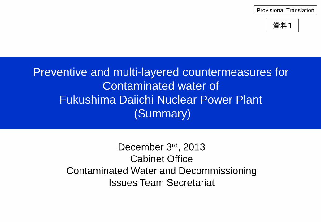
Flow of approachs at the Contaminated Water Treatment Committee
Understanding of Contaminated Water Status
Overall picture of measures Formulation of implementation
schedule plan
Gather domestic and overseas knowledge on the contaminated water issue.
Discuss with overseas experts.
Future vision of risk reduction
On-
Site
Con
tam
inat
ed W
ater
M
easu
res
Coo
rdin
atio
n M
eetin
g
Page 7
Verification of measure effect
Process management and coordination from an on-site viewpoint
Process management and coordination from an on-site viewpoint
Future problems
Visualize the location, concentration and capacity of contaminated water within the site.
Relatively evaluate risks and clarify high-priority measures.
Analyze the risk reduction effect.
Reorganize the information on underground water and geological condition.
Rebuild an underground flow analysis model
Analyze the effect of each measure.
Tritiated water task force
Pages 3 & 4 Pages 5 & 6
Underground water behavior understanding subgroup Risk evaluation subgroup
Pages 8 to 11
3
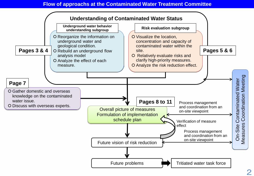
Overview of “Underground Water and Rainwater Behavior Analysis and Visualization” Subgroup (1)
Checked the boring results and underground water level measurement results conducted by TEPCO so far, and the data on the interrelations between secular change of the underground water level and rainfall, and reorganized the underground water and geological structures within the site.
Checked the validity of the simulation model used for deciding the existing contaminated water treatment measures.
To study the preventive and multi-layered measures, it is necessary to understand an overall picture of underground water flow, including the periphery of the Fukushima Daiichi site. For this reason, the target area of the simulation model was expanded beyond the site boundaries.
Compared the analysis results with the actual measurement data to check reproducibility of the new simulation model.
Stratum cross-sectional view of the south side of Fukushima Daiichi NPP, No. 4 reactor (East-west cross section)
Analytical water level vs. Actual measured value
Site boundaries (Outline)
0
5
10
15
20
25
30
35
40
0 5 10 15 20 25 30 35 40
実測水位(m)
解析
水位
(m)
建屋海側建屋山側35m盤
35-A-4
35-C-4
35-B-4
山側揚水井
地下貯水槽周辺
【Analysis results of the underground contour and flow direction diagram】
Stratus cross-sectional view of Fukushima Daiichi NPP , 35-m base (North-south cross section)
[Major analysis conditions] 1. Rainfall: Annual average rainfall 1,545 mm (1.3 mm/day) 2. Rainfall permeability: 55% (Evapotranspiration was assumed to be annually
700 mm, the maximum theoretical point evaporation value.) 3. Coefficient of permeability of structure, etc.: A coefficient of permeability was
set for 23 kinds of strata and structures in total. 4. Boundary condition: The conditions on the sea- and mountain side of the
analytical area were set as a hydrostatic pressure. (Analyzed inflow and outflow of underground water at the boundary in advance) Bundaryof old
analysis model
Legend of columnar section Legend of geological condition Backfilling earth Clay, silt Sand Stone Mudstone Sandy mudstone Pelitic sandstone Sand stone Tuff Pumice
Backfilling earth Quaternary deposit, Terrace sedimentary layer Tomioka deposit, T3 member, medium-grained sandstone layer (Layer I) Tomioka deposit, T3 member, alternation section (Layers III) Tomioka deposit, T3 member, fine-grained sandstone layer (Layer IV) Tomioka deposit, T3 member, fine-grained sandstone layer (Layer IV) Tomioka deposit, T3 member, coarse-grained sandstone layer (Layer IV) Tomioka deposit, T2 member Tuff key bed
Mudstone layer held in the medium-grained sandstone
layer
Cross section (14)-(14)’
In-hole water level and underground water level lines
Medium-grained sandstone (Layer I)
Alternation (Layer III)
Cross-sectional position
Width : Height
Sea side of building Mountain side of building 35-m base
Ana
lytic
al w
ater
leve
l (m
)
Measured water level
Periphery of underground water tank
Mountain-side pumping well
Underground water level (O.P.m)
Range of No. 1 to No. 4 model
Cross section (3)-(3)’ Width : Height

4
Study Overview at “Underground Water and Rainwater Behavior Understanding & Visualization” Subgroup (2)
Based on the reviewed underground water simulation, the effect of inhibiting inflow of underground water into the building was analyzed when each measure is implemented individually or in combination. Over 50 cases were analyzed as to the effect of combining the measures
Case
Measures Inflow volume into building (Daily)
Inflow volume into sea
area (Daily)
Pumping
volume (Daily)
Items of pumping volume
4-m base
measure
Underground water
bypass
Sea-side
water impermeable wall
Mountain-side
SD
Mountain-/sea-
side SD
Land-side
water impermeable wall
Facing゙ Mountain-side water impermeab
le wall
Total amount
Nos.1 to 4
buildings
Underground water
bypass SD
Sea-side drain
No measure 400 310 290 400
Case 1 410 320 220 460 50
Case 2 390 330 290
300 250 210
220 200 210
900 1220 1130
460 840 790
50
Case 3 400 320 0 750 350
Case 4 140 90 190 1000 820 40
Case 5 120 80 180 1070 920 30
Case 6 130 30 100 140 10
Case 7 Entire area 130 110 90 130 0
Case 8 * 300 240 170 330 30
Case 9 :Inside site boundary 420 330 220 470 50
Case 10 70 0 0 1010 500 290 140
Case 11 130 30 0 270
Case 12 130 30 0 770
Case 13 60 20 0 1370 830 150
Case 14 * ** 30 0 0 400 140 130 90
Case 15 * ** 110 30 0 210 90
Case 16 * ** 100 30 0 340 150 90
Case 17 * ** 60 40 0 560 10 430 40
.
Typi
cal C
ases
and
The
ir A
naly
sis
Res
ults
The following describes major matters clarified by comparing the analysis results of the effect of combining the measures for inhibiting inflow of underground water.
[Facts clarified by these analysis results] (1) Implementation of mountain-/sea-side sub-drain and
installation of the land-side water impermeable wall are highly effective in inhibiting inflow of underground water into the building. (Based on Cases 4, 5 and 6)
(2) Wide-range facing is highly effective in inhibiting inflow of underground water into the building, but its effect is limited if a construction area is narrowed. (Based on Cases 7 and 8
(3) Even if the mountain-side water impermeable wall is installed near the site boundary, the effect of inhibiting inflow of underground water into the building is not obtained. (Based on Case 9)
(4) The effect of inhibiting inflow of underground water into the building is obtained to a certain degree by implementing the on-going measures and those decided to be carried out. (Based on Case 10)
(5) The effect of the on-going measures or those decided to be carried out is increased by facing and peripheral water-shielding. However, it takes time to see the effect of facing and peripheral water-shielding. (Based on Cases 10 and 17
(6) Even if the land-side water impermeable wall fails to exhibit its full function, it can be substituted for by a combination of facing and the mountain-side water impermeable wall. (Based on Cases 10, 14 and 17)
As a result of the unsteady analysis of facing, it was found out that it took a longer period to exhibit the effects of measures, compared with a frozen soil wall implemented near the building (it takes approx. 42 months or longer to exhibit about half of expected effects).
Unsteady analysis results of facing *: Denotes the 35- and 10-m base water-proof pavement **: Denotes the combination of partial facing and peripheral water-shielding
The effects of underground water bypass and sub-drain depend on operating conditions.
1
2
3 4
5
6
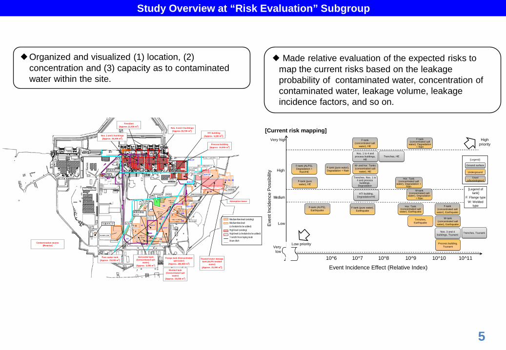
Study Overview at “Risk Evaluation” Subgroup
Organized and visualized (1) location, (2) concentration and (3) capacity as to contaminated water within the site.
Made relative evaluation of the expected risks to map the current risks based on the leakage probability of contaminated water, concentration of contaminated water, leakage volume, leakage incidence factors, and so on.
5
セシウム吸着塔
仮保管施設
恒設受変電設備
中低レベル
排水用
2.12ha
淡水化
Aエリア
H2
H9
H3
Bエリア
H7
Dエリア
Hエリア
バッファタンク
Medium/low level (existing)Medium/low level(scheduled to be added)High level (existing)High level (scheduled to be added)Transfer hose laying routeDrain ditch
中低レベル
排水用
1.57haH4
無線局舎
Gエリア
滞留水処理設備制御室
H8
処理水移送ポンプ
地下貯水槽
地下貯水槽地下貯水槽
中低レベル
排水用
2.14ha汚染処理排水
0.53ha
中低レベル
排水用1.32ha
ⅲ
ⅱ
ⅵ
ⅴ
ⅶ
ⅰ
ⅳ
中低レベル排水用タンク
Eエリア
H1
多核種除去設備
H5中低レベル排水用
1.40ha
H6
G3・G4・G5
G6
Cエリア
淡水化装置
淡水化淡水化地下貯水槽
セシウム吸着塔
一時保管施設
セシウム吸着塔
一時保管施設
ろ過水タンク 地下貯水槽
廃スラッジ貯蔵施設
高レベル滞留水受タンク
炉注水ポンプ
Adsorption tower
Treated water storagetank (ALPS treated
water)[Approx. 21,000 m3]
Flange tank (Concentratedsalt water)
[Approx. 250,000 m3]
Pure water tank[Approx. 29,000 m3]
Process building[Approx. 14,040 m3]
HTI building[Approx. 4,100 m3]
Trenches[Approx.11,000 m3] Nos. 3 and 4 buildings
[Approx.39,700 m3]
Nos. 1 and 2 buildings[Approx. 35,300 m3]
Contamination source[Reserve]
Horizontal tank(Concentrated salt
water)[Approx. 3,000 m3]
Welded tank(Concentrated salt
water)[Approx. 30,000 m3]
Event Incidence Effect (Relative Index)Ev
ent I
ncid
ence
Pos
sibi
lity High
Medium
Low
Very low
F-tank (concentrated salt water), Earthquake
F-tank (concentrated salt water), Earthquake
High priority
10^1010^7
Hor. Tank (concentrated salt water), Earthquake
Hor. Tank (concentrated salt water), Earthquake
F-tank (pure water), Earthquake
F-tank (pure water), Earthquake
Trenches, EarthquakeTrenches,
Earthquake
Trenches, HETrenches, HE
F-tank (concentrated salt
water), Degradation + Rain
F-tank (concentrated salt
water), Degradation + Rain
Hor. Tank (concentrated salt
water), Degradation + Rain
Hor. Tank (concentrated salt
water), Degradation + Rain
10^910^810^6
Nos. 1 to 4 and process buildings,
HE
Nos. 1 to 4 and process buildings,
HE
W- and hor. Tanks (concentrated salt
water), HE
W- and hor. Tanks (concentrated salt
water), HE
Trenches, Nos. 1 to 4 and process
buildings, Degradation
Trenches, Nos. 1 to 4 and process
buildings, Degradation
F-tank (pure water), Degradation + RainF-tank (pure water), Degradation + Rain
Trenches, TsunamiTrenches, TsunamiNos. 3 and 4 buildings, Tsunami
Nos. 3 and 4 buildings, Tsunami
10^11
Process building, Tsunami
Process building, Tsunami
W-tank (concentrated salt
water), Degradation + Rain
W-tank (concentrated salt
water), Degradation + Rain
F-tank (ALPS), Earthquake
F-tank (ALPS), Earthquake
F-tank (ALPS), Degradation +
Rain/HE
F-tank (ALPS), Degradation +
Rain/HE
[Legend of tank]
F: Flange typeW: Welded
type
W-tank (concentrated salt water), Earthquake
W-tank (concentrated salt water), Earthquake
[Legend]
Ground surfaceGround surface
UndergroundUnderground
Ground surface/underground
Ground surface/underground
[Legend]
Ground surfaceGround surface
UndergroundUnderground
Ground surface/underground
Ground surface/undergroundF-tank (pure
water), HEF-tank (pure water), HE
F-tank (concentrated salt
water), HE
F-tank (concentrated salt
water), HE
HTI building, Degradation/HE
HTI building, Degradation/HE
Very high
Low priority
[Current risk mapping]

6
Contaminated Water Event Occurrence Risk Map [Flange Tank/Aging Degradation]
Eve
nt In
cide
nce
Pos
sibi
lity
F-tank (Strong salt)Degradation +Rain
(1), (2) Raising of dam
(1), (2), (3) Enhanced patrol (Continued)Installation of water gauge
(1), (2), (3)Replacement/transfer of welded tank
(1), (2), (3)ALPS purificationNew ALPS purification
(1), (2), (3) Water-stopping by caulking
(1), (2), (3)Detection of microleakage
(1), (2), (3)Enhanced reliability of welded tank
(2), (3)Prevention of expansion beyond the area (Chemical injection, etc.)
(1) Change of ditch route to harbor
(1) Installation of sea-side impermeable wall
Event Incidence Effect (Relative Index)
High
Medium
Low
Very low
10^1010^7 10^910^810^6 10^11
Horizontal tank (Strong salt)Degradation
W-tank (Strong salt) Degradation + Rain
Black arrow: Measure decided to be implemented.Blue arrow: tratified measureDotted arrow: Denotes the measure effect difficult to be quantified and
having indefinite arrow length.
Outflow routes where measures work effectively(1) Tank to dam to ground surface to
ditch to sea(2) Tank to dam to underground to sea(3) Tank to underground to sea
*
*
* Almost same for the horizontal tank and W-tank.
Very high
Event Incidence Effect (Relative Index)E
vent
Inci
denc
e P
ossi
bilit
y
High
Medium
Low
Very low
High priority
10^1010^7 10^910^810^6 10^11
W-tank (ALPS)Earthquake
W-tank (ALPS)HE
[Tank legend]F: Flange type
W: Welded type
[Legend]Ground surface
Underground
Ground surface/underground
* The event incidence effect is only for partial reference because the measure effect is difficult to be quantified.
* There is no difference in the categories “High,” “Medium” and “Low” in “Event Incidence Possibility.”
Very high
[Verification of Risk Reduction Effect] (End of 2020)
Low priority
W-tank (ALPS)Degradation
Study Overview at “Risk Evaluation” Subgroup
The risk reduction effect of the measures over years to come was clarified when each measure is implemented according to their priority.
The measures contributing to risk reduction and their effects were analyzed as to individual risks.

Gathering of Domestic and Overseas Knowledge on Contaminated Water Problem
7
Invitation of technical proposals
A team of professionals was launched to gather domestic and overseas knowledge to receive technical proposals, centering around the International Research Institute for Nuclear Decommissioning (IRID). (Invitation period: Sep. 25 to Oct. 23)
The invited proposals were mainly scrutinized by the “Contaminated Water Treatment Committee” consisting of professionals
They are reflected on the overall picture of the preventive and stratified contaminated water treatment measures to be coordinated by the end of the year
State of application
There were 780 proposals. The following describes the details.
Field particularly asking for technical proposal/advice Proposal 1. Contaminated water storage (Storage tank, microleakage detection technique, etc.) 206 2. Contaminated water treatment (Tritium separation technique, long-term stable tritium storage method, etc.)
182
3. Purification of sea water in the harbor (Technique to eliminate radioactive Cs and Sr in sea water, etc.) 151 4. Contaminated water control in the building (Building internal water stop technique, ground improvement technique, etc.)
107
5. Site management for inhibiting inflow of underground water (Water-shielding wall construction technique, facing technique, etc.) 174 6. Understanding of behavior of underground water, etc. (Geological condition and underground water data measuring system, water quality analytical technique, etc.)
115
Others (Those not falling under 1 to 6 above) 34
Responses
Technique recom
mended to use
imm
ediately
Reliability improvement and scaling up of tank(Double steel shell tank, etc.)
Light-weight shielding sheet free from lead Pollution preventive membrane (silt fence, etc.) Water stop technique (building internal water stop,
building peripheral water stop) Survey of geological condition and underground
water, improvement observation network…
Technique recom
mended to
use after selection of suitable m
ethod
Technique of water-shielding (Facing of the site , peripheral water-shielding measure)
Technique to check/verify
Microleakage detection technique (dye included) Decontamination technique free from water. Technique of tritium storage and separation Purification of sea water in the harbor Underground filter (technique to collect strontium
in the soil) Unmanned boring technique
Evaluation /Study
Overall evaluation of handling of tritiated water Study on the possibility of responses to the
problems such as a floating tanker, underground storage (Note 1) The invitation fields are based on the applications of proposers.
(Note 2) Some single proposals are found out related to multiple fields.

8
Clarification of Expected Risks and Required Preventive and multi-layered Measures
Risk/Problem Measure taken by Sep. 3 or decided to be taken
Risks/P
roblems decided to be responded to
Risk of contaminated underground water flowing out into the sea
Contaminated water in sea-side trench
Pump and purify high-concentration contaminated water in the sea-side trench. [Removal]
Sea-side contaminated soil of the turbine building
Install sea-glass walls on the revetment of the sea-side contaminated area of the building. Pump contaminated water from the contaminated area. [No leakage]
Pave the ground surface of the sea-side contaminated area of the building with asphalt, etc. [No leakage]
Install the sea-side water-shielding walls in the harbor. [No leakage]
Contaminated water stored in the tanks
Enhance a patrol for the tanks and their piping. [No leakage] Install water gauges, leak detectors, etc. [No leakage] Replace the horizontal steel tanks. [No leakage] Accelerate replacement of bolted tanks by welded ones. [No leakage] Purify contaminated water by the ALPS (Advanced Liquid Processing System).
[Removal] Purify contaminated water by the higher-processing efficiency purification
equipment. [Removal] Collect the contaminated from the periphery of the tanks. [Removal]
Risk of contaminating underground water by leaked waste and allowing its outflow into the sea (Leakage from the high-performance container (HIC), etc. storing high-concentration waste after treated by the ALPS)
Reduce a waste volume by the higher-processing efficiency purification equipment. [No leakage]
Risk of increasing a contaminated water volume and failing to store it due to shortage of storage tanks, and so on
Pump underground water on the mountain side of the building (underground water bypass). [No access]
Pump underground water from the well near the building. (Sub-drain) [No access]
Install the land-side frozen soil based water-shielding walls which surround the buildings. [No access]
Install required additional tanks so as to surely store increasing contaminated water [No leakage]
Preventive and stratified measure expected to be required in addition to the left-mentioned
Improve the north-area soil of the No. 1 reactor’s intake. [No leakage] Remove the radioactive materials by installing the pollution preventive membranes. [No
leakage][Removal] Remove the radioactive materials in sea water. [No leakage][Removal] * Covering of marine soil.
Increasing the height of the embankment, installing the back-up embankment. [No leakage] Underdrain the ditches to prevent inflow of contaminated water. In addition, reroute the ditches to the
harbor. [No leakage] Further accelerate installation of welded tanks and improve reliability. (double steel shell tanks, etc.)
[No leakage] Install a rain gutter onto the tank top plate to inhibit rainwater stored in the dam. [No leakage] Stop a water leak by caulking the bottom of the bolted tanks, and so on. [No leakage] Decontaminate the used tanks consequent upon their replacement. [No leakage]* Prevent underground water contaminated by leak water from the tank from flowing out into the sea
(prevent expansion of contamination by chemical injection, and so on). [No leakage] Collect strontium in the soil. [No leakage]* Accelerate purification of contaminated water by expanding the multi-nuclide removal equipment
[Removal] Detect microleakage from the tank. [No leakage]*
Take measures to prevent a waste leak from the high-performance container (HIC) [No leakage] Reduce high-concentration waste further and formulate a stable storage measure. [No leakage]
Install new water-shielding walls outside the frozen soil walls, implement facing within the site, or implement a combination of them. [No access]
Appropriate treatment of tritiated water is to be studied by the tritiated water task force in a comprehensive manner.
Risk Preventive measures expected to be required in addition to the above-mentioned
Risks requiring future responses
Contaminated water leak from the circulative cooling system
Risk of contaminated water leaking from the building
Contaminated water leak from the building
Configure a circulation loop using the SPT as a buffer tank, exclude the HTI and process buildings gradually from the loop, thus reducing the loop by direct transfer of contaminated water of each reactor to the contaminated water treatment facility, and so on. [No leakage]
Shorten loops to remove contaminated water(Circulation contaminated water in the building). [Removal] Purify highly concentrated contaminated water in the building. Water stop of the building penetrating sections and the gaps between the buildings and so on. [No leakage]* Control the underground water level and contaminated water level by installation of drainage pumps in the deep sections of the reactor buildings, and
so on. [No leakage]
Outflow of building internal contaminated water into the sea by outer-rise tsunami
Improve waterproofness of the openings, etc. and considering additional countermeasures such as construction of sea walls [No leakage]
Leak from the transfer piping Take measures such as replacement by high-radiation resistance piping and multiplexing of piping. [No leakage]
Leak from the SARRY Take measures to prevent a contaminated water leak from the SARRY (install a leak receiver). [No leakage]
High-concentration waste after cesium removal Take measures to prevent waste leak from the cesium absorption tower [No leakage] Take measures for volume reduction and stable storage of waste from the cesium absorption tower. [No leakage]
Breakage of the tanks, etc. by large-scale natural disaster, etc. Build a system to prevent external discharge by swift transfer of a large amount of contaminated water to the building, etc., and so on. [No leakage]
(Note 1) In addition to the risks listed here, keep in mind that there may be other ones which cannot be accurately understood due to information shortage, etc. at this moment.
→ From now on, in the process of improving an observation network to enhance observation, make appropriate use of technique considered effective, according to its purpose of investigation.
• *: Denotes a measure to be verified about feasibility
• An underlined measure is introduced as a result of public invitation of techniques.
(1)Additional preventive & multi-layered
measures
(2) Further risk identification

Overall Picture of Contaminated Water Treatment Measures (Coordination by Contaminated Water Treatment Committee)
2. Additional counter measures (1) Multi-layered counter measures capable of responding to the risks if the existing measures are obstructed
[1] Measures for preventing underground water inflow [Isolation] (Additional measures) “Extensive facing ” or “Combination of partial facing and peripheral water-shielding”
(Existing measures) Land-side impermeable walls, pumping of underground water from the sub-drain, pumping by the underground bypass, and so on.
[2] Measures for contaminated water stored in the tanks, etc. [Removal] [No leakage] (Additional measures) Increasing the height of the embankment, Installing the back-up embankment, Covering
of ditches, capturing strontium in the soil, Reliable and larger tank(double steel shell tank, etc.), Microleakage detection device. (Existing measures) Clean-up of contaminated water by ALPS, introduction of high-performance clean-up system, acceleration of replacement by welded tanks, and so on.
[3] Measures for the sea-side areas [Removal] [No leakage] (Additional measures) Purification of sea water in the harbor such as precipitation, adsorption and separation,
Elimination of radioactive materials by membrane, covering of marine soil (Existing measures) Pumping of contaminated water in trenches, installation of water glass and sea-side impermeable walls, and so on.
[4] Measures against the risk of failing to store contamination water [No leakage] • Overall evaluation of handling of tritiated water • Study on the possibility of responses to the problems about a tanker, underground storage, and so on.
1. Results; (1)Checked the validity of underground water flow analysis model. About 800 ㎥/day of underground water was
supplied from the west side of the building, out of them 400 ㎥/day intruded into the building and the rest flowing into the port.
(2)Evaluated the potential risks and the remaining risks after taking each measures, based on the probability of leakage and radiological impacts from them. The impact of each risk reduction were clarified and prioritalised.
9
Overall Picture of Contaminated Water Treatment Measures (Coordination by Contaminated Water Treatment Committee)
10
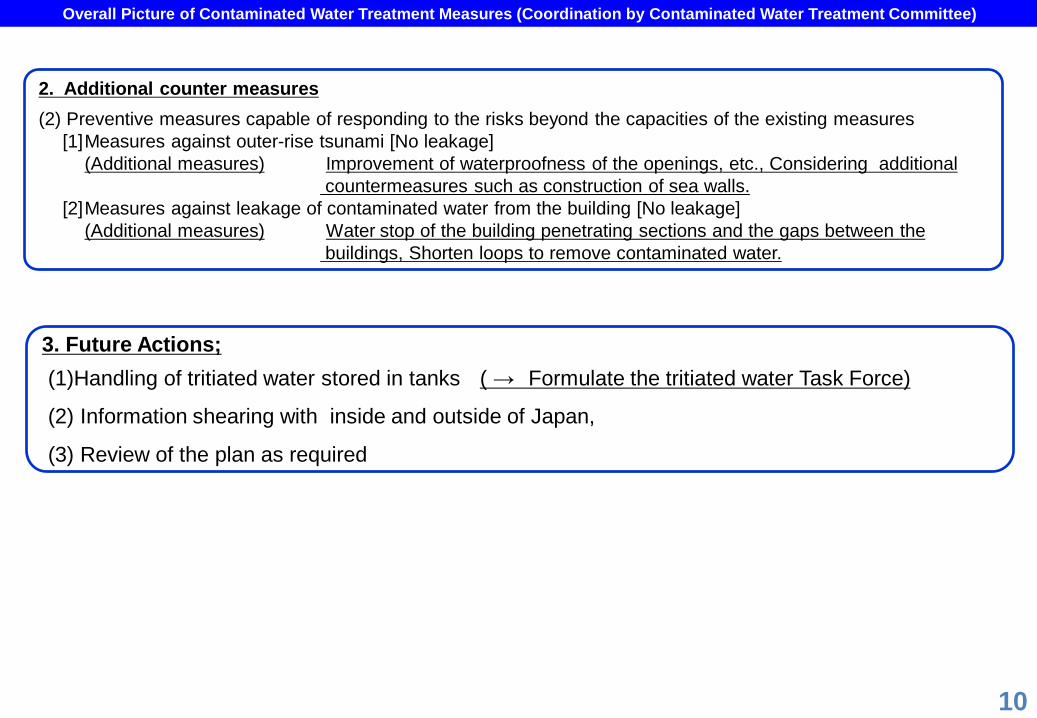
2. Additional counter measures (2) Preventive measures capable of responding to the risks beyond the capacities of the existing measures
[1] Measures against outer-rise tsunami [No leakage] (Additional measures) Improvement of waterproofness of the openings, etc., Considering additional
countermeasures such as construction of sea walls. [2] Measures against leakage of contaminated water from the building [No leakage]
(Additional measures) Water stop of the building penetrating sections and the gaps between the buildings, Shorten loops to remove contaminated water.
3. Future Actions; (1)Handling of tritiated water stored in tanks ( → Formulate the tritiated water Task Force)
(2) Information shearing with inside and outside of Japan,
(3) Review of the plan as required

Preventive and multi-layered countermeasures 1. “Extensive facing” or “Combination of partial facing and peripheral water-
shielding”.[Isolate] 2. Increase the height of the embankment, install the back-up embankment. [No leakage 3. Underdrain and reroute the drainage ditch to the harbor. [No leakage] 4. Further accelerate installation of welded tanks and improve reliability. [No leakage] 5. Detect microleakage from them . [No leakage] 6. Collect strontium contained in the soil. [Removal] 7. Reduce a contaminated water transfer loop. [No leakage] 8. Purify sea water in the harbor and cover the. marine soil. [Removal] [No leakage] 9. Remove the radioactive materials by the pollution preventive membranes. [Removal]
[No leakage] 10. Improve waterproofness of the openings, etc., Considering additional
countermeasures such as construction of sea walls. [No leakage] 11. Stop water leakage from the building penetrating sections and the gaps between the
buildings. [No leakage]
11
Overview of preventive and multi-layered counter measures 3 basic principles for contaminated water treatment measures 1. Isolate a contamination source. 2. Remove water close to the contamination source. 3. Prevent leak contaminated water.
Main measure taken after decision of basic policies on Sep. 3 or decided to be taken.
Purification of sea water in the harbor , covering of
marine soil [Removal]
Urgent measures
1. Eliminate high-concentration contaminated water in the trenches. [Removal]
2. Improve the soil of the contaminated area by water glasses, pave the ground surface with asphalt, etc. and pump underground water. [Isolate] [No leakage]
3. Pump underground water from the mountain side (underground water bypass) [Isolate]
Fundamental measures
1. Pump underground water by sub-drain. [Isolate]
2. Install the sea-side water-shielding walls. [No leakage]
3. Install the land-side water-shielding walls by the frozen soil method. [No access]
4. Prepare higher-processing efficiency contaminated water purification equipment. [Removal]
+
+
Sea-side water-shielding walls
Land-side frozen soil based water-shielding walls
Improvement of geological condition
Underdraining and rerouting the drainage ditch to the harbor
[No leakage]
Microleakage detection from tanks
[No leakage]
Further accelerating installation of welded tanks and improve reliability
[No leakage]
Increasing the height of the embankment, installing the
back-up embankment [No leakage]
Measure to be studied on its feasibility.
“Extensive facing” or “Combination of partial facing and peripheral water-shielding”
[Isolate]
Drainage ditch
Elimination of radioactive materials by pollution preventive membrane
[Removal]
Sub-drain Underground bypass
Stopping water leakage from the building penetrating sections and the gaps between the buildings
[No leakage]
Reducing a contaminated water transfer loop
[No leakage]
Collecting strontium contained in the soil
[Removal]
Improving waterproofness of the openings, etc., Considering additional countermeasures such as
construction of sea walls [No leakage]