
Prevention & suppression of dust
128
Wherever it may be encountered, dust is a nuisance. It reduces visibility’ causes discomfort and often irritation and causes can large amount of machinery to damage or mechanical equipment. Some kinds of dust, however, are more than just a nuisance. A coal dust form explosive mixtures with air and because of this has been the cause of mining disasters in which many thousands of lives have been lost. Other dusts may be toxic or even radioactive. A large group causes lungs diseases if inhaled in sufficient quantity over a large enough periods.
-
Upload
abhi24mining -
Category
Education
-
view
4.596 -
download
8
description
abhinandan
Transcript of Prevention & suppression of dust

Dust and dust diseases
Wherever it may be encountered, dust is a nuisance. It reduces visibility’ causes discomfort and often irritation and
causes can large amount of machinery to damage or mechanical equipment. Some kinds of dust, however, are
more than just a nuisance. A coal dust form explosive mixtures with air and because of this has been the cause of
mining disasters in which many thousands of lives have been lost. Other dusts may be toxic or even radioactive. A large
group causes lungs diseases if inhaled in sufficient quantity over a large enough periods.

Prevention of formation of dust
Production of fine dust during drilling can be minimized by using sharp bits so that there is more chipping than grinding action. Sufficient thrust on the bit and suitable arrangement for the clearance of cuttings from the hole help in reducing dust production. There is no difference in rotary and percussive drilling as regards the quantity of pathogenic dust produced by them. Dust production in rotary drilling is inversely proportional to the rate of penetration, though it varies directly with speed of rotation. Thus high thrust at a low rotational speed produces the minimum dust.

Prevention of dust getting air-borne
• This involves measures for suppressing the dust at the source of production and removing or consolidating the dust already deposited.
• These sources are described in further slides.

1. Drilling
Suppression of dust produced by drilling is achieved mainly by adopting wet drilling.•Wet drilling has proved very effective in dust suppression. whereas the dust concentration during dry drilling may be as high as 5000 p.p.c.c. or more, it is brought down to only 200 to 400 p.p.c.c. By the use of wet drilling. For wet drilling to be effective, the pressure of water should be sufficient, but too high a pressure reduces the rate of penetration by cushioning the cutting action and hence should be avoided.
• A good pressure is about 75 kpa less than the pressure of air
(i.e. 400-500 kpa). The amount of water fed into the hole
should be at least 3×10⁻³ m3 min-1 for effecting proper dust suppression.
• Wet percussive drills commonly used today incorporate an internal water feed arrangement where water is fed at the shank end of the hollow drill steel by means of a water tube passing through the piston of the drill and entering into the drill steel up to a length of about ten millimetres from the shank end.

• Nowadays rotary drills have also been fitted with external flush-head for heads for water flushing through hollow drill steels. However, external flush-heads usually cause a loss of energy varying from 5 to 15% due to friction between the shank and the flush-head.
• Where water is scarce, foam can be used for suppressing dust. Foam is usually produced by adding a small quantity (uaually1%) of a foaming agent like pyrene to water.

• The early designs of dry extractors consisted essentially of a hood sealing off the mouth of the hole and provided with two holes, one for the passage of the drill steel and the other connected to a suitable exhaust system for cleaning the dust from the hole. The KELLY DUST-TRAP commonly used in the U.S.A. in nineteen hundred and thirties consisted of a heavy metal shield connected to an exhaust system through a settling chamber and a filter.

2. Coal winning
• winning of coal by coal cutting machines, continuous miners or pneumatic picks produces a lot of dust. Dust produced by pneumatic picks can be reduced by about 50% by using wet pneumatic picks. Suppression of dust produced by coal-cutting machines is usually done by water sprays incorporated in the machine. There are usually four or five jets, 6mm in diameter provided at different parts of the jib for spraying the gummings at the source of production. These sprays are usually fed by internal water feed-pipes fitted inside the jib. The reduction of dust concentration by wet cutting varies between 80 to 90% of the dust produced by dry cutting.
3. Loading
• Much dust can be raised by loading dry material. That is why it is desirable to wet the muck pile by water sprays before loading.
4. Water infusion• Cleavages and cracks in coal seams usually contain a large
quantity of fine dust which is set free during the process of winning. Such dust can be suitably allayed by infusing the coal with water under pressure.

• Usually holes 50mm in diameter and 1.8m long are drilled at 3 to 5m interval along a face. The holes should be drilled at right angles to the cleavage planes; thus it may be necessary to drill holes inclined to the face (flanking holes).
• In British coal mines, water infusion has been claimed to achieve about 75% reduction in the dust concentration at the face. In addition to suppressing dust, water infusion loosen the coal to some extent, thus making its winning easier.

5. Pulsed infusion
• The loosening of coal with water infusion led to the development of pulsed infusion. Here, a pulse or shock is imparted to the water in the hole by firing an explosive charge in it so that the loosening effect is enhanced in addition to suppressing dust. Flanking holes inclined at an angle of 0.8 rad (=45) to the face are commonly used for pulsed infusion. They are about 2-3.5m long and spaced at 1.8m intervals. The holes are first charged with the requisite quantity of explosive and then the infusion tube is inserted, the seal tightened and the hole infused with water under pressure for about 15-20 minutes before the shot is fired.

• Pulsed infusion may be sufficient to blast coal in the solid depending on the nature of coal, but it is also extensively used for blasting undercut faces. The amount of explosive used for solid blasting is about 250 to 350g/hole. Sometimes pulsed infusion with a lesser quantity of explosive (150-250g) may be done in the solid in order to loosen the coal ploughs or cutter-loaders. Long holes drilled parallel to the face at a distance 1.5m have been fired by pulsed infusion.

6. Water Stemming
• This consists of stemming a shot hole after charging with a plastic or p.v.c. bag (usually 0.15mm thick) filled with water. Water, owing to its incompressibility, gives a better confinement to the charge so that a better efficiency of blasting is obtained. This usually results in a saving of about 25% in the explosive consumption. Water stemming produces less dust, the reduction in the dust concentration being 50-70% of the dust produced by blasting with ordinary clay stemming.

Removal of deposited dust
• Often, dust deposited on the floor of mine roadways can become air-borne by high velocity air-current, trampling by men etc. A vacuum-cleaning device has been designed for removing the dust deposited on roadways.
• The dust is delivered first to a cyclone for the separation of coarse particles and then to a filter for collecting the finer dust.

Consolidation of roadway dust
• The best method of preventing roadway dust getting air-borne is to consolidate it. The simplest method of consolidation is by wetting the dust with water sprays, but water sprays alone do not produce good wetting of all deposited dust and a large quantity of water may be needed for producing effective results.
• Besides, water evaporates quickly needing very frequent spraying. Two common methods of consolidating roadway dust are:- 1. Calcium Chloride method2. Salt Crust Process

Calcium Chloride Method
• This method utilized the principle of keeping the dust constantly and thoroughly wetted so that it takes on the consistency of a paste. To this end, the dust is first sprayed with water mixed with a suitable wetting agent and then sprinkled over with calcium chloride. Calcium chloride, being hygroscopic, absorbs moisture from the air and keeps the dust wet. Subsequent trampling by men further helps in the consolidation of the dust.
• The amount of calcium chloride depends on the relative humidity of the air and generally varies between 2 to 7% of the dust.

• A single treatment lasts for a period which may be anything from a couple of months to a year depending on the rate of deposition of dust.
• The method is unsuitable for a heavy rate of deposition so that it becomes imperative to use this method of consolidating roadway dust only in conjunction with suitable suppressive measures adopted at the face and other points of dust generation.

Salt Crust Process
• Here, unlike the calcium chloride method, the dust is bound up in the form of a crust. The method consists of sprinkling common salt on the dust and then spraying it with water. Initially water amounting to about 15% of the weight of the salt used is sprayed. The salt dissolves and penetrates into the dust, but soon, the water starts evaporating, thus causing the salt to recrystallize and form a hard crust on the surface. Particles of dust are trapped in the growing salt crystals and thus consolidated.

• As fresh dust is deposited on the crust, it becomes necessary to respray it so that the salt can dissolve and recrystallize entrapping the freshly deposited dust. The amount of water to be sprayed subsequently should be such that it ensures a high rate of crystallization, maintaining at the same time a firm crust. The salt crust process has been found to be unsuitable for very high (>75%) and very low (<55%) humidities and because of this many German mines are now using the calcium chloride process.

DILUTION AND SUPRESSION OF AIR-BORNE DUST
• Introduction The simplest way of reducing the
concentration of dust in air to a pathologically safe limit is to dilute it by increasing the quantity of ventilation. But large concentration would require a large quantity of air which will increase the cost of ventilation and also create high air velocities which may raise deposited dust.

• Suppression of air-borne dust ,can be classified into two method :-
1) Wet suppression 2) Dry suppression

Water jet at crushing plant
• Wet suppression : Wet dust suppression
systems use liquids (usually water) to wet the material so that it has a lower tendency to generate dust. Keeping the material damp immobilizes the dust, and very little material becomes airborne.
This technique suppresses airborne dust by spraying fine droplets of water on the dust cloud. The water droplets and dust particles collide and form agglomerates. Once these agglomerates become too heavy to remain airborne, they settle from the air stream.

Wet Dust Suppression System
Wet dust suppression systems wet the entire product stream so that it generates less dust. This also prevents dust from becoming airborne. Effective wetting of the material can be achieved by-
1. Static Spreading - The material is wetted while stationary. The diameter and contact angle of water droplets are important factors in static spreading.
2. Dynamic Spreading - The material is wetted while moving. The surface tension of the liquid, the droplet diameter, the material size, and the droplet impact velocity are important variables in dynamic spreadingContact Angle of a Water Droplet
Droplet with surfactant added
Plain water droplet
Contact angle

Wet Dust Suppression System
Factors Affecting Surface Wetting-1. Droplet Size :Surface wetting can be increased by reducing the
droplet diameter and increasing the number of droplets. This can be achieved by reducing the surface tension/contact angle. The surface tension of pure water is 72.6 dyne/cm. It can be reduced from 72.6 to 28 dyne/cm by adding minute quantities of surfactants. This reduction in surface tension (or contact angle) results in-
• Reduced droplet diameter• An increase in the number of droplets• A decrease in the contact angle
2. Impact Velocity :Surface wetting can be increased by increasing the impact velocity.Impact Velocity can be increased by increasing the system's operating pressure.

Water sprinkler fitted in dumper.
• Wet suppression :Fine atomized sprays or mist
sprays having droplets of about 60µm diameter have been found much more effective in wetting suspended dust than coarse sprays.
Automatic sprays can be produced by swirl type pressure nozzel or by pneumatic atomizers.

• Wet suppression :Pressure nozzles for producing
fine droplets usually require high water pressure(of the order of4-5 MPa) and very small nozzle diameter(0.2-0.5mm).
The nozzle should be carefully finished. Slight nozzle wear destroys the uniformity of atomization.

Why water-spray systems?
Dry collection systems are very efficient. However, this technology is capital intensive, high maintenance and ,Filter fabrics have limitations with stacking materials in a pile and the disposal of filters \ fabrics often produce secondary emissions.
Water spray systems remain the most efficient and cost effective means of dust control for both process and fugitive dust emissions. Reason; the dust remains with the product of origin, while it is being disturbed.
fig.1 Spray-generated airflow carries dust back tothe shearer operator.

Types of Wet Dust Suppression Systems
Wet suppression systems fall into three categories:1. Plain Water Sprays - This method uses plain water to wet
the material. However, it is difficult to wet most surfaces with plain water due to its high surface tension.
2. Water Sprays with Surfactant - This method uses surfactants to lower the surface tension of water. The droplets spread further and penetrate deeper into the material pile.
3. Foam - Water and a special blend of surfactant make the foam. The foam increases the surface area per unit volume, which increases wetting efficiency.

Advantages Disadvantages
Plain Water Sprays It is probably the least expensive
method of dust control. Water sprays cannot be used for
products that cannot tolerate excessive moisture.
The system is simple to design and operate
Water sprays cannot be used when temperatures fall below freezing.
A limited carryover effect at subsequent transfer points is possible
Usually, dust control efficiency is low, unless large quantities of water are used.
When good mixing of water and material can be achieved, dust generation can be reduced effectively.
Freeze protection of all hardware is necessary
Enclosure tightness is not essential. Careful application at transfer points that precede a screen is required to prevent blinding.

Water Sprays With SurfactantsAdvantages
• This method is used when surfactants are tolerated but excessive moisture is not acceptable.
Disadvantages
• Capital and operating costs are higher than water-spray systems.
• In some cases, dust control efficiency is higher than with plain water sprays.
• Careful application at transfer points that precede a screen is required to prevent blinding.
• Equivalent efficiency is possible with less water.
• Equipment such as the pump and proportioning equipment used to meter the flow of surfactant require maintenance.
• Freeze protection of all hardware is necessary
Foam• When good mixing of foam and product
stream can be achieved, dust control efficiency is greater than water with surfactants.
• Operating costs are higher than with finely atomized water-spray systems.
• Moisture addition is usually less than 0.1% of the material weight.
. product is contaminated with surfactants.
. Careful application at transfer points that precede a screen is required to prevent blinding.

Design of a Water-Spray System • The spray nozzle is the heart of a water-spray system. Factors
such as droplet size distribution and velocity, spray pattern and angle, and water flow rate and pressure all vary depending on the nozzle selected. Following is a general discussion of these important factors: 1. Droplet Size- The nozzle's droplet size distribution is the most important
variable for proper dust control. The droplet size decreases as the operating pressure increases. Information about the droplet size data at various operating pressures can be obtained from the nozzle manufacturer. For wet dust suppression systems, coarse droplets (200-500 µm) are recommended. For airborne dust capture systems, very fine droplets (10-150 µm) may be required. The fine droplets usually are generated by fogging nozzles, which may use either compressed air or high-pressure water to atomize water in the desired droplet range.
2. Droplet Velocity - Normally, higher droplet velocities are desirable for both types of dust control through water sprays. Information on the droplet velocity can be obtained from the nozzle manufacturer.

Design of a Water-Spray System
3. Spray Pattern - Nozzles are categorized by the spray patterns they produce:
a. Solid-cone nozzles product droplets that maintain a high velocity over a distance. They are useful for providing a high-velocity spray when the nozzle is located distant from the area where dust control is desired.
b. Hollow-cone nozzles produce a spray patter in the form of circular ring. Droplet range is normally smaller than the other types of nozzles. They are useful for operations where dust is widely dispersed.
Solid-Cone Noozle
Hollow-ConeNozzle

c. Flat-spray nozzles produce relatively large droplets that are delivered at a high pressure. These nozzles are normally useful for wet dust suppression systems (i.e., preventive type systems)
d. Fogging nozzles produce a very fine mist (a droplet size distribution ranging from submicron to micron). They are useful for airborne dust control systems.
Design of a Water-Spray System
Flat-spray nozzle
Fogging nozzle

Design of a Water-Spray System
4. Spray Angle - Each nozzle has a jet spray angle. The size of this angle is normally available from the manufacturer. A knowledge of spray angle and spray pattern is essential to determine the area of coverage and, therefore, the total number of nozzles needed.
5. Flow Rate - The flow rate of water through a nozzle depends on the operating pressure. The flow rate and operating pressure are related as follows:
where K = nozzle constant
Spray distance
Specified spray angle
Actual coverage
Wat
er fl
ow
Water pressure

The following factors should be considered in selecting the nozzle location: • It should be readily accessible for maintenance.• It should not be in the path of flying material.• For wet dust suppression systems, nozzles should be upstream of the
transfer point where dust emissions are being created. Care should be taken locate nozzles for best mixing of material and water. For airborne dust capture, nozzles should be located to provide maximum time for the water droplets to interact with the airborne dust.
Water Flow and Compressed Airflow Rates :
Once the nozzle is selected, its spray pattern and area of coverage can be used to determine water flow rate and/or compressed airflow rates and pressure requirements. This information is normally published by the nozzle manufacturer. These must be carefully coordinated with the maximum allowable water usage. Water flow rates will be highly variable depending on the size and type of material, the type of machinery, and the throughput of material.
Design of a Water-Spray System

Wet suppression
Water sprays have been effectively used for suppressing dust at following places :-
• Haulage roads• Chutes• Transfer points• ore bins• skip loading stations• Coal cutting machines• Ore/mineral/coal handling
plant etc.

Wet suppression
Drawbacks:• Undesirable in deep and hot mines where it
may increase the humidity.• Dust suppressed by water can again become
air-borne if allowed to dry up.• Water causes detrimental effects on machinary
and conveyors etc.

Dry dust suppression
• Introduction This usually consists of exhausting the dusty air from
the point of operation and then separating the dust from the air by inertial separation, filtering, electrical precipitation etc. so that cleaned air can be recirculated.
Means of dry dust suppression are commonly used in mines at transfer points, ore bin, crusher stations and even for cleaning the air after blasting in headings.

Dust Collection System
• Dust Collection System: The dust collection system, also known as the local exhaust ventilation system, is one of the most effective ways to reduce dust emissions. A typical dust collection system consists of four major components:
1. Exhaust hood :to capture dust emissions at the source
2. Ductwork: to transport the captured dust to a dust collector
3. Dust collector :to remove the dust from the air
4. Fan and Motor :to provide the necessary exhaust volume and energy. Components of Dust Collection System
Exhaust hood
Dust collector
Fan &motor
ductwork

1. Exhaust Hood The exhaust hood is the point where dust-filled air enters a dust collection system. Its importance in a dust collection system cannot be overestimated. It must capture dust emissions efficiently to prevent or reduce worker exposure to dusts. The exhaust hood- • Encloses the dust producing operation• Captures dust particulates and guides dust laden air efficiently
• Types of Exhaust Hoods The three general classes of exhaust hoods are- a) Local hoodsb) Side, downdraft and canopy hoodsc) Booths or enclosures

Types of Exhaust Hoods
• Local hood
• Side, downdraft and canopy hoods
• Booth and enclosure hood

1. Local hoods: They are relatively small structures. They are normally located close to the point of dust generation and capture the dust before it escapes. Local hoods are generally efficient and typically used for processes such as abrasive grinding and woodworking.
2. Side, downdraft, and canopy hoods : They are larger versions of local hoods. They also rely on the concept of preventing dust emissions beyond the control zone. They are typically used for plating tank exhausts, foundry shakeouts, melting furnaces, etc. These hoods are generally less efficient than local hoods.
3. Booth and enclosure hoods : They isolate the dust generating process from the workplace and maintain an inward flow of air through all openings to prevent the escape of dust. These hoods are the most popular type in minerals processing operations because they are very efficient at minimum exhaust volumes. They are typically used for areas such as vibrating or rotating screens, belt conveyors, bucket elevators, and storage bins.
Types of Exhaust Hoods

Design of Exhaust Hoods • The design of an exhaust hood requires sufficient knowledge of
the process or operation so that the most effective hood or enclosure (one requiring minimum exhaust volumes with desired collection efficiency) can be installed. The successful design of an exhaust hood depends on-
a. Rate of airflow through the hood b. Location of the hood c. Shape of the hood
• Of the above three factors, the rate of airflow through the exhaust hood (that is, the exhaust volume rate) is the most important factor for all types of hoods.
• For local, side, downdraft, and canopy hoods, the location is equally important because the rate of airflow is based on the relative distance between the hood and the source.
• The shape of the exhaust hood is another design consideration. If the hood shape is not selected properly, considerable static pressure losses may result.

• Rate of Airflow - Two approaches used in minerals processing operations to determine the rate of airflow needed through a hood are-
I. Air inductionII. Control velocity
I. Air Induction - The air-induction concept is based on the theory that when granular material falls through the air each solid particle imparts some momentum to the surrounding air. Due to this energy transfer, a stream of air travels with the material. Unless the air is removed it will escape through all openings upon material impact, carrying the fine dust particles with it. For adequate control of dust emissions, the exhaust air volume rate must be equal to or greater than the air-induction rate.
The air-induction phenomenon is of great significance in calculating exhaust volumes. The concept can be applied to many transfer points normally found in minerals processing operations because the calculations are based on variables such as the material feed rate, its height of free fall, its size, and its bulk density.
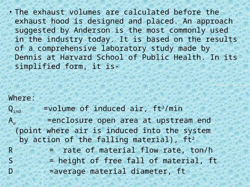
• The exhaust volumes are calculated before the exhaust hood is designed and placed. An approach suggested by Anderson is the most commonly used in the industry today. It is based on the results of a comprehensive laboratory study made by Dennis at Harvard School of Public Health. In its simplified form, it is-
Where: Qind =volume of induced air, ft3/min
Au =enclosure open area at upstream end (point where air is induced into the system
by action of the falling material), ft2
R = rate of material flow rate, ton/hS = height of free fall of material, ftD =average material diameter, ft

II.Control Velocity - In the control-velocity approach, the exhaust hood is designed before exhaust volumes are computed.
This approach is based on the principle that, by creating sufficient airflow past a dust source, the dusty air can be directed into an exhaust hood. The air velocity required to overcome the opposing air currents and capture the dusty air is known as capture velocity. Dallavalle investigated the air-velocity pattern in a space adjoining an exhaust/suction opening and developed the folowing equation to determine exhaust volume:
Q = Vx (10X2 + A)
Where: Q = exhaust volume, ft3/min Vx = centerline velocity (i.e.,
capture velocity) at distance X from hood, ft/min
X = distance outwards along the hood axis, ft
A = area of hood face opening, ft2
Control-Velocity Approach

Location of the Exhaust Hood
• The location of the exhaust hood is important in achieving maximum dust-capture efficiency at minimum exhaust volumes. When the control-velocity approach is used, the location of the hood is critical because exhaust volume varies in relation to the location and size of the exhaust hood. The location of the exhaust hood is not as critical when the air-induction approach is used.

Location of the Exhaust Hood The air-induction approach requires the hood to be located
as far from the material impact point as possible to- • Prevent capturing coarse dust particles, which settle
quickly.• Capture only fine, predominantly respirable dust.• Reduce unnecessary transport of coarse dust through
ductwork and thus reduce dust settling in horizontal duct runs.
• Reduce dust loading (dust concentration) in the exhaust gases.
• Minimize subsequent cleaning and disposal of the collected dust.
• Prevent capture of valuable products, especially in ore- concentrating operations.

Location of the Exhaust Hood
The control-velocity approach requires the hood to be located as close to the source as possible to-
• Maximize the hood capture efficiency for a given volume• Reduce the exhaust volume requirements• Enclose the source as much as possible

Location of the Exhaust Hood
EXHAUST HOOD
PRIMARY CRUSHER
ENCLOSURE

Shape of the Exhaust Hood Sizable pressure losses may occur if the shape
of the exhaust hood is not designed properly. These pressure losses are due to the mutual conversion of static and velocity pressures.
The following points should be considered in selecting the shape of the hood: • The exhaust hood shape with the highest
coefficient of entry value, Ce, or the lowest hood entry loss factor, he, should be selected. Various values of Ce and he are described in the following table:
• Wherever possible, the hood should be flanged to eliminate airflow from zones containing no contaminants.
• This measure can reduce exhaust air volume up to 25%. For most applications, the flange width should not exceed 6 in.
Effect of Flanged Opening

• Ductwork :The ductwork transports the dust captured by the exhaust
hood to a dust collector. Efficient transport of captured dust is necessary for effective and reliable system operation.Ductwork Design :
Ductwork design includes the selection of duct sizes based on the velocity necessary to carry the dust to the collector without settling in the duct. From this information, pressure losses in the duct and exhaust air volumes can be calculated and used to determine the size and type of fan, as well s the speed and size of motor.

Before detailed design of the ductwork is begun, the following information should be available:
• A process flowsheet of the operation indicating- :– Type, size, and speed of the bulk material handling or
processing equipment used • A line diagram of the dust collection system indicating- :
– Exhaust hood and exhaust volumes required for each piece of equipment, each transfer point, and each duct network
– Each branch and section of the main duct, identified either by number or letter
• A general layout of the facility showing- :– All equipment in the plan and elevations – The ductwork route and location of the exhaust hood – Location of the dust collector and the fan

• A preliminary bill of material containing-:– Length of each duct.– Number and type of elbows, transition, and taper pieces,
etc. – Number and size of "y" branches for each branch and main
as identified in the process flowsheet. Proper ductwork design-– Maintains adequate transport velocities in the duct to
prevent particulate settling .– Provides proper air distribution in all branches to maintain
designed capture velocities of exhaust hoods .– Minimizes pressure losses, wear, and abrasion of ductwork
thus reducing operating costs .

Collecting and Disposing of Dust
• What is a Dust Collector?– After dust-filled air has been captured by a dry dust collection
system, it must be separated, collected, and disposed of. The dust collector separates dust particles from the airstream and discharges cleaned air either into the atmosphere or back into the workplace.
• Necessity for Dust Collectors • Cleaning dust from the air is necessary to-– Reduce employee exposure to dust – Comply with health and air emission standards – Reduce nuisance and dust exposure to neighbors – Recover valuable products from the air
• Types of Dust Collectors– Five principal types of industrial dust collectors
are-1. Inertial separators 2. Fabric collectors 3. Wet scrubbers 4. Electrostatic precipitators 5. Unit collectors

Inertial Separators
• Inertial separators separate dust from gas streams using a combination of forces, such as centrifugal, gravitational, and inertial. These forces move the dust to an area where the forces exerted by the gas stream are minimal. The separated dust is moved by gravity into a hopper, where it is temporarily stored.

The three primary types of inertial separators are-
Settling chambers
Baffle chambers
Centrifugal collectors

Settling Chambers
A settling chamber consists of a large box installed in the ductwork. The sudden expansion of size at the chamber reduces the speed of the dust-filled airstream and heavier particles settle out.
Settling chambers are simple in design and can be manufactured from almost any material. However, they are seldom used as primary dust collectors because of their large space requirements and low efficiency. A practical use is as precleaners for more efficient collectors.

Baffle Chambers Baffle chambers use a fixed baffle plate that causes the conveying gas stream to make a sudden change of direction. Large-diameter particles do not follow the gas stream but continue into a dead air space and settle. Baffle chambers are used as precleaners for more efficient collectors.
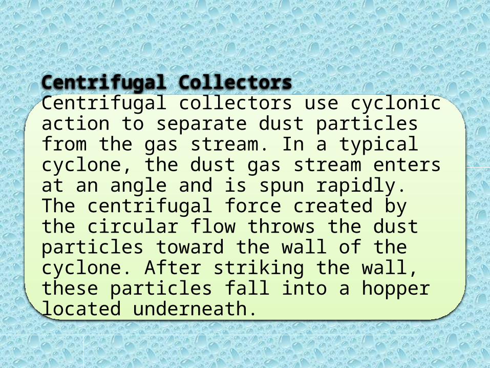
Centrifugal CollectorsCentrifugal collectors use cyclonic action to separate dust particles from the gas stream. In a typical cyclone, the dust gas stream enters at an angle and is spun rapidly. The centrifugal force created by the circular flow throws the dust particles toward the wall of the cyclone. After striking the wall, these particles fall into a hopper located underneath.

• The most common types of centrifugal, or inertial, collectors in use are-1. Single-cyclone
separators
2. Multiple-cyclone separators
Outer vortex
Inner vortex

1. Single-cyclone separators: It create a dual vortex to separate coarse from fine dust. The main vortex spirals downward and carries most of the coarser dust particles. The inner vortex, created near the bottom of the cyclone, spirals upward and carries finer dust particles.
2. Multiple-cyclone separators: It consist of a number of small-diameter cyclones, operating in parallel and having a common gas inlet and outlet, as shown in the figure. Multi-clones operate on the same principle as cyclones--creating a main downward vortex and an ascending inner vortex.
Note:Multiclones are more efficient than single cyclones because they are longer and smaller in diameter. The longer length provides longer residence time while the smaller diameter creates greater centrifugal force. These two factors result in better separation of dust particulates.
The pressure drop of multiclone collectors is higher than that of single-cyclone separators.
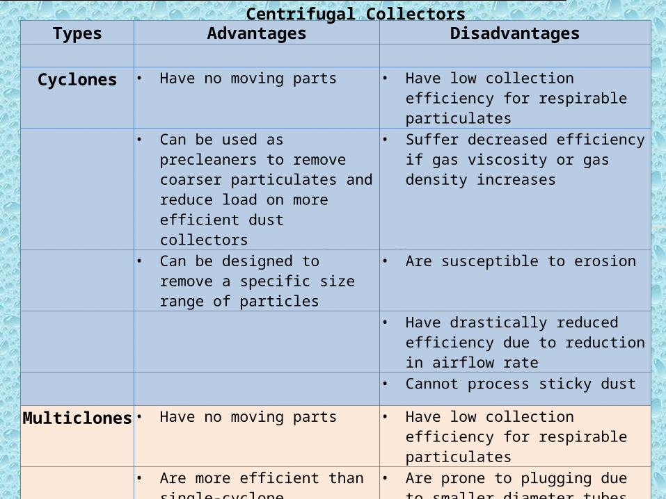
Advantages and Disadvantages - Centrifugal Collectors
Types Advantages Disadvantages
Cyclones • Have no moving parts • Have low collection efficiency for respirable particulates
• Can be used as precleaners to remove coarser particulates and reduce load on more efficient dust collectors
• Suffer decreased efficiency if gas viscosity or gas density increases
• Can be designed to remove a specific size range of particles
• Are susceptible to erosion
• Have drastically reduced efficiency due to reduction in airflow rate
• Cannot process sticky dust
Multiclones • Have no moving parts • Have low collection efficiency for respirable particulates
• Are more efficient than single-cyclone separators
• Are prone to plugging due to smaller diameter tubes
• Have low pressure drop when used
as a precleaner• Improper gas distribution may result in
dirty gas bypassing several tubes
• Cannot process sticky dust
• For a given gas volume, occupy more space than single-cyclone separators
• Normally have higher pressure drop than single-cyclone separators
Centrifugal Collectors
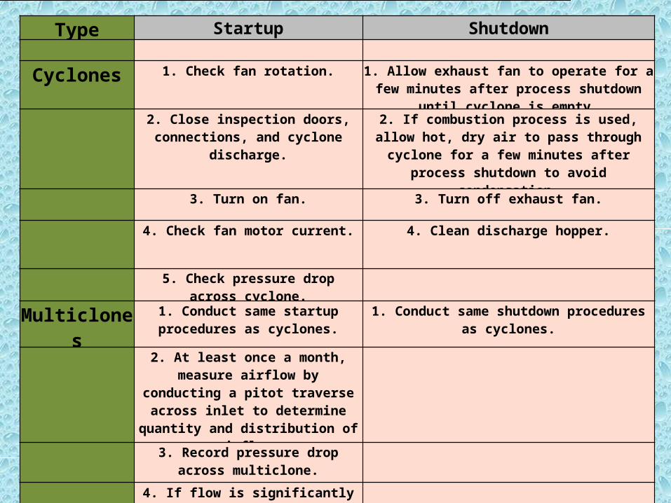
Startup/Shutdown Procedures - Centrifugal Collectors
Type Startup Shutdown
Cyclones 1. Check fan rotation. 1. Allow exhaust fan to operate for a few minutes after process shutdown until cyclone is empty.
2. Close inspection doors, connections, and cyclone discharge.
2. If combustion process is used, allow hot, dry air to pass through cyclone for a few minutes after process
shutdown to avoid condensation.
3. Turn on fan. 3. Turn off exhaust fan.
4. Check fan motor current. 4. Clean discharge hopper.
5. Check pressure drop across cyclone.
Multiclones 1. Conduct same startup procedures as cyclones.
1. Conduct same shutdown procedures as cyclones.
2. At least once a month, measure airflow by conducting a pitot traverse across inlet to determine quantity and distribution of
airflow.
3. Record pressure drop across
multiclone.
4. If flow is significantly less than desired, block off rows of cyclone to maintain the
necessary flow per cyclone.

Preventative Maintenance Procedures - Centrifugal Collectors
Type Frequency Procedure
Cyclones Daily Record cyclone pressure drops.
Check stack (if cyclone is only collector).
Record fan motor amperage.
Inspect dust discharge hopper to assure dust is removed.
Weekly Check fan bearings.
Check gaskets, valves, and other openings for leakage.
Monthly Check cyclone interior for erosion, wear, corrosion, and other visible signs of deterioration.
Multiclones Daily Same as cyclones.
Weekly Same as cyclones.
Monthly Check multiclone interior for erosion, wear, corrosion, and improper gas and dust distribution.
Inspect individual cyclones and ducts for cracks caused by thermal expansion or normal wear.

Fabric collectorCommonly known as baghouses, fabric collectors use filtration to separate dust particulates from dusty gases. They are one of the most efficient and cost effective types of dust collectors available and can achieve a collection efficiency of more than 99% for very fine particulates.
Clean air
Dirty air
Filter bags
baghouse

Fabric collector
• How They Work ?Dust-laden gases enter the baghouse and pass through fabric bags that act as filters. The bags can be of woven or felted cotton, synthetic, or glass-fiber material in either a tube or envelope shape.The high efficiency of these collectors is due to the dust cake formed on the surfaces of the bags. The fabric primarily provides a surface on which dust particulates collect through the following four mechanisms:
a. Inertial Collection - Dust particles strike the fibers placed perpendicular to the gas-flow direction instead of changing direction with the gas stream.
b. Interception - Particles that do not cross the fluid streamlines come in contact with fibers because of the fiber size.
c. Brownian Movement - Submicron particles are diffused, increasing the probability of contact between the particles and collecting surfaces.
d. Electrostatic Forces - The presence of an electrostatic charge on the particles and the filter can increase dust capture.
A combination of these mechanisms results in formation of the dust cake on the filter, which eventually increases the resistance to gas flow.

Types of BaghousesAs classified by cleaning method, three
common types of baghouses are-
Mechanical shaker Reverse air Reverse jet

• Mechanical-Shaker BaghouseIn mechanical-shaker baghouses, tubular filter
bags are fastened onto a cell plate at the bottom of the baghouse and suspended from horizontal beams at the top. Dirty gas enters the bottom of the baghouse and passes through the filter, and the dust collects on the inside surface of the bags.
Cleaning a mechanical-shaker baghouse is accomplished by shaking the top horizontal bar from which the bags are suspended. Vibration produced by a motor-driven shaft and cam creates waves in the bags to shake off the dust cake.
Shaker baghouses range in size from small, handshaker devices to large, compartmentalized units. They can operate intermittently or continuously. Intermittent units can be used when processes operate on a batch basis-when a batch is completed, the baghouse can be cleaned. Continuous processes use compartmentalized baghouses; when one compartment is being cleaned, the airflow can be diverted to other compartments.
In shaker baghouses, there must be no positive pressure inside the bags during the shake cycle.

• Reverse Air In reverse-air baghouses, the bags are fastened
onto a cell plate at the bottom of the baghouse and suspended from an adjustable hanger frame at the top. Dirty gas flow normally enters the baghouse and passes through the bag from the inside, and the dust collects on the inside of the bags.
Reverse-air baghouses are compartmentalized to allow continuous operation. Before a cleaning cycle begins, filtration is stopped in the compartment to be cleaned. Bags are cleaned by injecting clean air into the dust collector in a reverse direction, which pressurizes the compartment. The pressure makes the bags collapse partially, causing the dust cake to crack and fall into the hopper below. At the end of the cleaning cycle, reverse airflow is discontinued, and the compartment is returned to the main stream.
The flow of the dirty gas helps maintain the shape of the bag. However, to prevent total collapse and fabric chafing during the cleaning cycle, rigid rings are sewn into the bags at intervals.
maintenance is somewhat greater.

• Reverse JetIn reverse-jet baghouses, individual bags are supported
by a metal cage, which is fastened onto a cell plate at the top of the baghouse. Dirty gas enters from the bottom of the baghouse and flows from outside to inside the bags. The metal cage prevents collapse of the bag.
Bags are cleaned by a short burst of compressed air injected through a common manifold over a row of bags. The compressed air is accelerated by a venturi nozzle mounted at the top of the bag. Since the duration of the compressed-air burst is short (0.1s), it acts as a rapidly moving air bubble, traveling through the entire length of the bag and causing the bag surfaces to flex. This flexing of the bags breaks the dust cake, and the dislodged dust falls into a storage hopper below.
Reverse-jet dust collectors can be operated continuously and cleaned without interruption of flow because the burst of compressed air is very small compared with the total volume of dusty air through the collector. Because of this continuous-cleaning feature, reverse-jet dust collectors are usually not compartmentalized.
The short cleaning cycle of reverse-jet collectors reduces recirculation and redeposit of dust. These collectors provide more complete cleaning and reconditioning of bags than shaker or reverse-air cleaning methods.

Preventive Maintenance Procedures - Baghouses
Frequency Procedure
Daily • Check pressure drop. • Observe stack (visually or with opacity meter). • Walk through system, listening for proper operation. • Check for unusual occurrences in process. • Observe control panel indicators. • Check compressed-air pressure. • Assure that dust is being removed from system.
Weekly • Inspect screw-conveyor bearings for lubrication. • Check packing glands. • Operate damper valves. • Check compressed-air lines, including line filters and dryers. • Check that valves are opening and closing properly in bag-cleaning sequence. • Spot-check bag tension. • Verify accuracy of temperature-indicating equipment. • Check pressure-drop-indicating equipment for plugged lines. •
Monthly • Check all moving parts in shaker mechanism. • Inspect fans for corrosion and material buildup. • Check drive belts for wear and tension. • Inspect and lubricate appropriate items. • Spot check for bag leaks. • Check hoses and clamps. • Check accuracy of indicating equipment. • Inspect housing for corrosion.
Quarterly • Inspect baffle plate for wear. • Inspect bags thoroughly. • Check duct for dust buildup. • Observe damper valves for proper seating. • Check gaskets on doors. • Inspect paint, insulation, etc. • Check screw conveyor for wear or abrasion.
Annually • Check fan belts. • Check welds. • Inspect hopper for wear.

Wet Scrubbers
Dust collectors that use liquid are commonly known as wet scrubbers. In these systems, the scrubbing liquid (usually water) comes into contact with a gas stream containing dust particles. The greater the contact of the gas and liquid streams, the higher the dust removal efficiency.

• There is a large variety of wet scrubbers; however, all have of three basic operations: 1. Gas-Humidification - The gas-humidification process conditions fine
particles to increase their size so they can be collected more easily.2. Gas-Liquid Contact - This is one of the most important factors
affecting collection efficiency. The particle and droplet come into contact by four primary mechanisms:
a. Inertial Impaction - When water droplets placed in the path of a dust-laden gas stream, the stream separates and flows around them. Due to inertial, the larger dust particles will continue on in a straight path, hit the droplets, and become encapsulated.
b. Interception - Finer particles moving within a gas stream do not hit droplets directly but brush against them and adhere to them.
c. Diffusion - When liquid droplets are scattered among dust particles, the particles are deposited on the droplet surfaces by Brownian movement, or diffusion. This is the principal mechanism in the collection of submicron dust particles.
d. Condensation Nucleation - If a gas passing through a scrubber is cooled below the dewpoint, condensation of moisture occurs on the dust particles. This increase in particle size makes collection easier.

3. Gas-Liquid Separation - Regardless of the contact mechanism used, as much liquid and dust as possible must be removed. Once contact is made, dust particulates and water droplets combine to form agglomerates. As the agglomerates grow larger, they settle into a collector.
• The "cleaned" gases are normally passed through a mist eliminator (demister pads) to remove water droplets from the gas stream. The dirty water from the scrubber system is either cleaned and discharged or recycled to the scrubber. Dust is removed from the scrubber in a clarification unit or a drag chain tank. In both systems solid material settles on the bottom of the tank. A drag chain system removes the sludge and deposits in into a dumpster or stockpile.

Types of Scrubbers •Low-energy
scrubbers (0.5 to 2.5)•Low- to medium-
energy scrubbers (2.5 to 6)
•Medium- to high-energy scrubbers (6 to 15)
•High-energy scrubbers (greater than 15)
Wet scrubbers may be
categorized by pressure drop
(in inches water gauge) as follows:

Advantages and Disadvantages - Wet Scrubbers
Advantages Disadvantages
• Have low capital costs and small space requirements
• Have high operating and maintenance costs
• Can treat high-temperature and high-humidity gas streams
• Require corrosion-resistant materials if used with acidic gases
• Are able to collect gases as well as particulates (especially "sticky" particulates)
• Require a precleaner for heavy dust loadings
• Have no secondary dust sources • Cause water pollution; require further water treatment
Are susceptible to erosion at high velocities
Collect wet products
Require freeze protection
Wet Scrubbers

Preventative Maintenance Procedures - Wet Scrubbers
Frequency Procedure
Daily • Check recycle flow. • Check bleed flow. • Measure temperature rise across motor. • Check fan and pump bearings every 8 hours for oil level, oil color, oil temperature, and
vibration. • Check scrubber pressure drop. • Check pump discharge pressure. • Check fan inlet and outlet pressure. • Check slurry bleed concentration. • Check vibration of fan for buildup or bleeds. • Record inlet and saturation temperature of gas stream. • Use motor current readings to detect flow decreases. Use fan current to indicate gas flow. • Check pressure drop across mesh and baffle mist eliminators. Clean by high-pressure spraying,
if necessary.Weekly • Check wet/dry line areas for material buildup. Clean, if necessary.
• Check liquid spray quantity and manifold pressure on mist eliminator automatic washdown. • Inspect fans on dirty applications for corrosion, abrasion, and particulate buildup. • Check bearings, drive mechanisms, temperature rise, sprocket alignment, sprocket wear, chain
tension, oil level, and clarifier rakes. • Check ductwork for leakage and excessive flexing, Line or replace as necessary. • Clean and dry pneumatic lines associated with monitoring instrumentation.
Wet Scrubbers

Electrostatic Precipitators
Electrostatic Precipitators

Electrostatic Precipitators
• The airborne particles receive a negative charge as they pass through the ionized field between the electrodes. These charged particles are then attracted to a grounded or positively charged electrode and adhere to it.
• The collected material on the electrodes is removed by rapping or vibrating the collecting electrodes either continuously or at a predetermined interval. Cleaning a precipitator can usually be done without interrupting the airflow.
The four main components of all electrostatic precipitators are- :a. Power supply unit, to provide high-voltage, unidirectional currentb. Ionizing section, to impart a charge to particulates in the gas streamc. A means of removing the collected particulatesd. A housing to enclose the precipitator zone

The following factors affect the efficiency of electrostatic precipitators:• Larger collection-surface areas and lower gas-flow rates
increase efficiency because of the increased time available for electrical activity to treat the dust particles.
• An increase in the dust-particle migration velocity to the collecting electrodes increases efficiency. The migration velocity can be increased by- Decreasing the gas viscosity Increasing the gas temperature Increasing the voltage field

Types of Precipitators
•High-Voltage, Single-Stage :-Single-stage precipitators combine an ionization and a collection step. They are commonly referred to as Cottrell precipitators.
•Low-Voltage, Two-Stage :- precipitators use a similar principle; however, the ionizing section is followed by collection plates.
There are two main types of precipitators:

• High-Voltage, Single-Stage Precipitators
The two major types of high-voltage precipitators currently used are-
1. Plate2. Tubular

Plate Precipitators - The majority of electrostatic precipitators installed are the plate type.
• Particles are collected on flat, parallel surfaces that are 8 to 12 in. apart, with a series of discharge electrodes spaced along the centerline of two adjacent plates.
• The contaminated gases pass through the passage between the plates, and the particles become charged and adhere to the collection plates. Collected particles are usually removed by rapping the plates and deposited in bins or hoppers at the base of the precipitator.
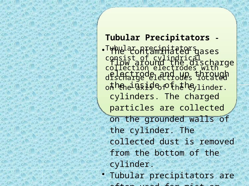
Tubular Precipitators - Tubular precipitators consist of cylindrical collection electrodes with discharge electrodes located on the axis of the cylinder.
• The contaminated gases flow around the discharge electrode and up through the inside of the cylinders. The charged particles are collected on the grounded walls of the cylinder. The collected dust is removed from the bottom of the cylinder.
• Tubular precipitators are often used for mist or fog collection or for adhesive, sticky, radioactive, or extremely toxic materials.

Advantages and Disadvantages - Electrostatic Precipitators
Advantages Disadvantages
• Have collection efficiencies in excess of 99% for all particulates, including sub-micron-sized particles
• Have high initial investment costs
• Usually collect dust by dry methods • Do not respond well to process changes such as changes in gas temperature, gas pressure, gas flow rate, gaseous or chemical composition, dust loading, particulate size distribution, or electrical conductivity of the dust
• Have lower pressure drop and therefore lower operating costs
• Have a risk of explosion when gas stream contains combustibles
• Can operate at high temperatures (up to 1200º F) and in colder climates
• Product ozone during gas ionization
• Can remove acids and tars (sticky dust) as well as corrosive materials
• Require large space for high efficiency, and even larger space for dust with low or high resistivity characteristics
• Allow increase in collection efficiency by increasing precipitator size
• Require special precautions to protect personnel from exposure to high-voltage
• Require little power • Require highly skilled maintenance personnel
• Can effectively handle relatively large gas flows (up to 2,000,000 ft3/min)
Advantages and Disadvantages - Electrostatic Precipitators

Unit Collectors
Unlike central collectors, unit collectors control contamination at its source. They are small and self-contained, consisting of a fan and some form of dust collector. They are suitable for isolated, portable, or frequently moved dust-producing operations, such as bins and silos or remote belt-conveyor transfer points.
Advantages of unit collectors are:• small space requirements• the return of collected dust to main material
flow, • and low initial cost. However, their dust-
holding and storage capacities, servicing facilities, and maintenance periods have been sacrificed.

A number of designs are available, with capacities ranging from 200 to 2,000 ft3/min.
• There are two main types of unit collectors:
1. Fabric collectors- with manual shaking or pulse-jet cleaning - normally used for fine dust.
2. Cyclone collectors - normally used for coarse dust.

Fabric collectors are frequently used in minerals processing operations because they provide high collection efficiency and uninterrupted exhaust airflow between cleaning cycles. Cyclone collectors are used when coarser dust is generated, as in woodworking, metal grinding, or machining.
The following points should be considered when selecting a unit collector: • Cleaning efficiency must comply will all applicable regulations.• The unit should maintain its rated capacity while accumulating large
amounts of dust between cleanings.• The cleaning operations should be simple and should not increase
the surrounding dust concentration.• The unit should be capable of operating unattended for extended
periods of time (for example, 8 hours).• The unit should have an automatic discharge or sufficient dust
storage space to hold at least 1 week's accumulation.• If renewable filters are used, they should not have to be replaced
more than once a month.• The unit should be durable.• The unit should be quiet.

Selecting a Dust Collector Dust collectors vary widely in design, operation, effectiveness, space
requirements, construction, and capital, operating, and maintenance costs. Each type has advantages and disadvantages. However, the selection of a dust collector should be based on the following general factors:
• Dust Concentration and Particle Size - For minerals processing operations, the dust concentration can range from 0.1 to 5.0 grains of dust per cubic feet of air, and the particle size can vary from 0.5 to 100 µm.
• Degree of Dust Collection Required - The degree of dust collection required depends on its potential as a health hazard or public nuisance, the plant location, the allowable emission rate, the nature of the dust, its salvage value. The selection of a collector should be based on the efficiency required and should consider the need for high-efficiency, high-cost equipment, such as electrostatic precipitators; high-efficiency, moderate-cost equipment, such as baghouses or wet scrubbers; or lower cost, primary units, such as dry centrifugal collectors.

Selecting a Dust Collector• Characteristics of Dust - Moderate to heavy concentrations of many dusts (such
as dust from silica sand or metal ores) can be abrasive to dry centrifugal collectors. Hygroscopic material can blind bag collectors. Sticky material can adhere to collector elements and plug passages. Some particle sizes and shapes may rule out certain types of fabric collectors. The combustible nature of many fine materials rules out the use of electrostatic precipitators.
• Methods of Disposal - Methods of dust removal and disposal vary with the material, plant process, volume, and type of collector used. Collectors can unload continuously or in batches. Dry materials can create secondary dust problems during unloading and disposal that do not occur with wet collectors. Disposal of wet slurry or sludge can be an additional material-handling problem; sewer or water pollution problems can result if wastewater is not treated properly.
• Characteristics of Airstream - The characteristics of the airstream can have a significant impact on collector selection. For example, cotton fabric filters cannot be used where air temperatures exceed 180º F. Also, condensation of steam or water vapor can blind bags. Various chemicals can attach fabric or metal and cause corrosion in wet scrubbers.

Disposal of Dusty Air
• After dust-laden exhaust gases are cleaned, the collected dust must be disposed of properly. Ideally, dust can be returned to the product stream and sold; if this is not possible, disposal of dust may become a problem. For example, when dry dust collectors are used, secondary dust problems may arise during unloading and disposal of collected dust; for wet dust collectors, the disposal of wet slurry or sludge can be a problem.

Disposal of Dusty Air
• The simplest way to dispose of dusty air is through a stack or a long pipe which discharges the air at a remote point where air pollution is inconsiquential. Such stack very in height from 15m upwards.
• The dust concentration at any point downward of a stack depends on the :– stack height, – the rate of dust emission from stack and – the wind velocity.

• Proper disposal of collected dust can be accomplished in four steps: i. Removing dust from the hopper of the dust
collectorii. Conveying the dustiii. Storing the dustiv. Treating the dust for final disposal

Removing Dust from Hopper
• Collected dust must be removed continuously (while the dust collector is operating), rotary air locks or tipping valves should be used to maintain a positive air seal. If the material in the hopper has a bridging tendency, equipment such as bin vibrators, rappers, or air jets should be used.

Conveying the Dust• After the dust has been removed from the collector, it must be
transported to a central point for accumulation and ultimate disposal. Conveying of dust can be accomplished by the following methods: Use of screw conveyors Use of air conveyors (pneumatic conveying) Use of air slides (low-pressure pneumatic conveying) Use of pumps and piping systems to convey slurry Screw conveyors have been used with a great deal of success.
However, trouble areas to be considered are maintenance access, worn-out bearings and casings due to abrasive materials, and air leaks. For wet dust collectors, inclined conveyors can be used to convey the slurry to a settling pond.
Pneumatic conveyors are often selected to convey dry dust because they have few moving parts and can convey either horizontally or vertically. They operated on a high-velocity, low-air-volume principle. Trouble areas include excessive wear and abrasion in the piping and high capital and operating costs.

• Air slides are commonly used for nonabrasive, light dust. They work on the principle of air fluidization of dust particles and are useful for heavy horizontal conveying. Trouble areas include ability to maintain a certain downward slope and greater maintenance requirements.
Pumps and piping systems are used to convey the slurry to a settling pond. However, care must be taken in this method to prevent water-pollution.

Storing the Dust• After the material has been removed and transported from the
dust collector, a storage facility must be used to permit disposal in efficient quantities. Elevated storage tanks or silos are normally used to permit loading of dry dust into enclosed trucks underneath.
For wet dust collectors, the accumulation area is a settling pond. A settling pond may require considerable space. Since the storage area can only be decanted and dried out during the dry season, two settling ponds are usually needed. Also, most collected materials have very fine components that may seal the pond and prevent percolation.
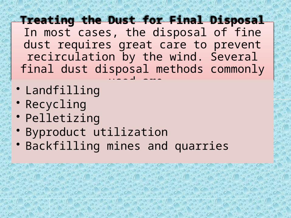
Treating the Dust for Final DisposalIn most cases, the disposal of fine dust requires great care to prevent recirculation by the wind. Several final
dust disposal methods commonly used are-
• Landfilling• Recycling• Pelletizing• Byproduct utilization• Backfilling mines and quarries

DUST CONTROL METHODS IN TUNNELSAND UNDERGROUND MINES
• In This : Ventilation: dilution and displacement Water sprays: wetting and airborne capture Water additives: foam and wetting agents Dust collectors: filtration efficiency and inlet
capture efficiency Reducing the generation of dust for cutting,
drilling, blasting, crushing, and conveying

VENTILATION Ventilation air reduces dust by dilution and by
displacement. Displacement ventilation is far more effective, but it is harder to implement.
• The dilution mechanism operates when workers are surrounded by a dust cloud and additional air serves to reduce the dust concentration by diluting the cloud.
• The displacement mechanism operates when workers are upwind of dust sources and the air velocity is high enough to reliably keep the dust downwind.

• Dilution Ventilation – The basic principle behind dilution ventilation is to
provide more air and dilute the dust. Most of the time the dust is reduced roughly in proportion to the increase in airflow, but not always. The cost of and technical barriers to increased airflow can be substantial, particularly where air already moves through ventilation ductwork or shafts at velocities of 3,000 ft/min or more.

• Displacement VentilationThe basic principle behind displacement ventilation is to use the airflow in a way that confines the dust source and keeps it away from workers by putting dust downwind of the workers. Every tunnel or mine passage with an airflow direction that puts dust downwind of workers uses displacement ventilation.
In mines, continuous miner faces or tunnel boring machines on exhaust ventilation use displacement ventilation. Enclosure of a dust source, such as a conveyor belt transfer point, along with extraction of dusty air from the enclosure, is another example of displacement ventilation.

• Closed-face tunnel boring machine (TBM).—Cutter heads of hard-rock tunnel boring machines operate in an enclosed space, and they are high.
First, the stirring action of the large rotating cutter head creates a considerable amount of air turbulence. Second, there is far less enclosure of the cutter head than a casual inspection of a TBM would indicate. Depending on the TBM design, the entire belt conveyor access space can be open. Also, there is considerable open space when the grippers at the head expand to press out against the tunnel walls. Dust reduction efforts have focused on reducing the open space available for dust leakage by 6 enclosing the conveyor tunnel and by installing single or even double sets of rubber dust seals between the grippers and TBM body.

CONTINUOUS MINER DUST CONTROL
Design and operation of machine-mounted scrubbers• In relation to dust, there are following categories of
continuous miner faces depending on the type of ventilation and machine-mounted dust scrubber is used:1. Mining machines with dust scrubbers used with blowing face
ventilation2. Mining machines with dust scrubbers used with exhaust face
ventilation
• Almost all new continuous miners are equipped with scrubbers. When the dust is excessive, it is possible that the scrubber needs some maintenance.

Machine-mounted scrubbers, which are installed on continuous miners, collect dust-laden air through one or more inlets near the front of the miner and discharge cleaned air at the back of the miner. Fig. 2 shows a typical design. Inside the scrubber, the dustladenair passes through a knit wire-mesh filter panel that is wetted with water sprays, which causes the dust particles to be captured by the water. After passing through the filter panel, the airstream then enters a demister, which removes the dust-laden water droplets from the airstream.
The cleaned air passes through the fan and is then discharged at the back of the scrubber unit. Some scrubber designs have ductwork on the rear of the miner, which permits the discharge of air on either side of the machine.
Fig. 2 Machine-mounted scrubber design.
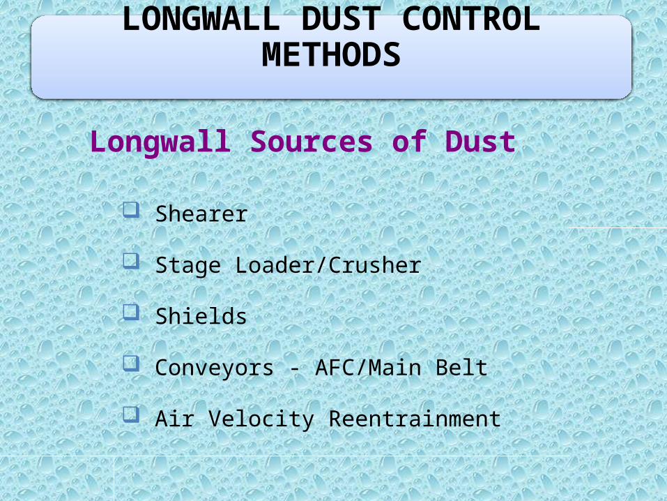
Longwall Sources of Dust
Shearer
Stage Loader/Crusher
Shields
Conveyors - AFC/Main Belt
Air Velocity Reentrainment
LONGWALL DUST CONTROL METHODS

Sources of Longwall Dust
Stage loader15%
Shearer53%
Shields23%
Intake9%

Typical Longwall Shearer
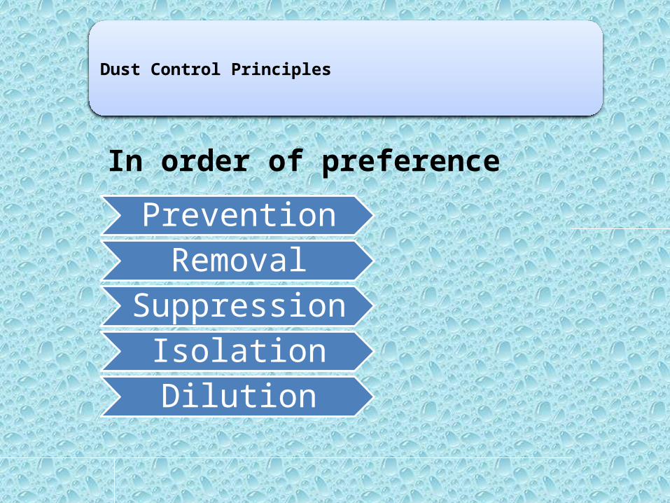
Dust Control Principles
In order of preference
PreventionRemoval
SuppressionIsolationDilution

Longwall Dust Control
Prevention reduces dust generation
Water Infusion
Foam Infusion
Deep Cutting
Slower Speed
Sharp Bits

Longwall Dust Control Removal prevents dust from becoming airborne
Dust collectors (Scrubbers)
Suppression makes it difficult for dust to become (or remain) airborne
Number of sprays
Pressure of sprays
Additives - Surfactants

Longwall Dust Control
Isolation: Keep dust away from minersKeep miners away from dust
Air curtains Air deflectors
Spray fans Shearer clearer
Remote control
Automation
Personal Protective Devices

Dilution reduces the ratio of the amount of dust in the air
Adequate Air
Prevent Leakage
Gob Curtain
Cut-Out Curtain
Use of Belt Air
Longwall Dust Control

Longwall Dust Problems
1. Inadequate air volume and air velocity
2. Insufficient water volume and pressure
3. Poorly designed external spray systems
4. Inadequate dust control at stage loader and crusher
5. Inadequate protection from shield dust
6. Poor operating practices which keep miners downwind of the shearer

Longwall Dust Control
Shearer Dust Control – Shearer design
Shearer Dust Control – Shearer Sprays
Shield Dust Control
Stage Loader/Crusher Dust Control
Modified Cutting Sequence – Uni-Di

Ventilation Controls – Gob curtain
Ventilation Controls – Wing curtain
Remote Control and Automation
Other Methods – e.g. Water infusion, foam, etc
Other Sources Control – Conveyors, reentrainment
Personal Protective Equipment – e.g. PAPR
Longwall Dust Control

Shearer Water Sprays

Shearer-Clearer System Operation

Instantaneous Dust Levels With and Without a Shearer Clearer

Shield Spray System

Stage Loader/Crusher

Goaf Curtain to Reduce Air Leakage into the Goaf at the Headgate
goafgoaf
goaf

Wing Curtain to Direct Air From the Headgate Cut-out Area

Multiple Controls in Modern Longwalls
1. Shearer-Cutting Sequence - Deep Cutting
Slow drum speed, Water sprays
Pick pushing, Shearer clearer
Remote control, Scrubbers
2. Shields - Washing Down, Sprays
3. Face/Main Conveyor Sprays

4. Stage Loader/Crusher-Banks of Sprays, Scrubber
5. Ventilation - Large Quantities
Reduce leakage
Gob curtains
Cut-out curtains
Multiple Controls in Modern Longwalls…contd

6. Administrative Control - Operational Practices, Cutting Sequences
7. Personal Protective DevicesAir helmetsRespirators
Other Controls in Modern Longwalls…contd


