Prevention of Contamination in the Metal Machining Sector ... · for Cleaner Production ... COLD...
112
p roduction CLEANER MEDITERRANEAN Ministry of the Environment Spain Regional Activity Centre for Cleaner Production Government of Catalonia Ministry of the Environment and Housing Regional Activity Centre for Cleaner Production (RAC/CP) Mediterranean Action Plan Metal Machining Sector Prevention of Contamination in the UNEP MAP
Transcript of Prevention of Contamination in the Metal Machining Sector ... · for Cleaner Production ... COLD...
productionCLEANER
MEDITERRANEAN
Ministry of the EnvironmentSpain
Regional Activity Centrefor Cleaner Production
Government of CataloniaMinistry of the Environmentand Housing
Regional Activity Centre for Cleaner Production (RAC/CP)Mediterranean Action Plan
Metal Machining Sector
Prevention ofContamination in the
UNEP
MAP

Ministry of the EnvironmentSpain
Regional Activity Centrefor Cleaner Production
Government of CataloniaMinistry of the Environmentand Housing
Regional Activity Centre for Cleaner Production (RAC/CP)Mediterranean Action Plan
Metal Machining Sector
Prevention ofContamination in the
UNEP
MAP

Note: This publication may be reproduced in whole or in part and in any form of educational and non-profit purposes without special permission from the Regional Activity Centre for Cleaner Production (RAC/CP), provided acknowledgement of the source is made. RAC/CP would appreciate receiving a copy of any publication that uses this material as a source. No use of this publication may be made for resale or for any other commercial purposes whatsoever without prior permission in writing from RAC/CP. If you consider that some part of this study could be improved or there is any lack of precision, we would appreciate if you could notify it to us. Study finished on April 2005
Study published on September 2005
Additional copies or information could be requested to: Regional Activity Centre for Cleaner Production (RAC/CP)
C/ París, 184 – 3rd floor 08036 Barcelona (Spain) Tel.: 00 34 93 415 11 12 – Fax: 00 34 93 237 02 86 e-mail: [email protected] Web page: http://www.cema-sa.org

5
TABLE OF CONTENTS
1. INTRODUCTION ..................................................................................................................................7 1.1. FOREWORD...............................................................................................................7 1.2. OBJECTIVES AND STRUCTURE ..............................................................................8 1.3. METHOD.....................................................................................................................8
2. PRODUCTION PROCESSES IN THE METAL MACHINING SECTOR AND ASSOCIATED ENVIRONMENTAL ISSUES .............................................................................................................11 2.1. THE METAL MACHINING SECTOR.........................................................................11 2.2. CUTTING FLUIDS.....................................................................................................12 2.3. COLD ROLLING........................................................................................................13
2.3.1. A brief description of the cold rolling process .................................................13 2.3.2. Cold rolling and environmental considerations ...............................................15
2.4. COLD WIRE DRAWING............................................................................................17 2.4.1. A brief description of the cold wire drawing process.......................................17 2.4.2. Cold wire drawing and environmental considerations ....................................18
2.5. COLD DRAWING......................................................................................................19 2.5.1. A brief description of the cold drawing process ..............................................19 2.5.2. Cold drawing and environmental considerations ............................................20
2.6. PUNCHING AND DEEP DRAWING .........................................................................21 2.6.1. A brief description of the punching and deep drawing processes...................21 2.6.2. Punching, deep drawing and environmental issues .......................................21
2.7. COLD FORMING BY BENDING ...............................................................................23 2.7.1. A brief description of the cold forming by bending process ............................23 2.7.2. Description of the cold forming by bending process and environmental issues ..23
2.8. MACHINING..............................................................................................................26 2.8.1. A brief description of the machining process ..................................................26 2.8.2. Machining processes and environmental considerations ...............................26
2.9. HEAT TREATMENTS ...............................................................................................29 2.9.1. Annealing........................................................................................................30 2.9.2. Quenching ......................................................................................................31 2.9.3. Tempering.......................................................................................................33
2.10. DEGREASING ..........................................................................................................35
3. ENVIRONMENTAL HAZARDS IN THE METAL MACHINING SECTOR .........................................39 3.1. WATER CONSUMPTION .........................................................................................39 3.2. ENERGY CONSUMPTION .......................................................................................41 3.3. LIQUID WASTE.........................................................................................................42 3.4. SOLID WASTE..........................................................................................................46
3.4.1. Discarded raw materials .................................................................................46 3.4.2. Sludge.............................................................................................................47 3.4.3. Other waste ....................................................................................................48
3.5. ATMOSPHERIC EMISSIONS...................................................................................49 3.6. NOISE .......................................................................................................................51
Prevention of Contamination in the Metal Machining Sector
6
4. OPPORTUNITIES FOR PREVENTING AND REDUCING POLLUTION..........................................53 4.1. MODIFICATION OF PRODUCTS.............................................................................55 4.2. GOOD HOUSEKEEPING PRACTICES....................................................................55 4.3. REPLACEMENT OF RAW MATERIALS...................................................................61 4.4. TECHNOLOGICAL CHANGES.................................................................................64 4.5. RECYCLING AT SOURCE .......................................................................................70 4.6. END TREATMENT....................................................................................................78
5. CASE HISTORIES .............................................................................................................................83 5.1. CASE HISTORY 1: COMPONENTES MECÁNICOS, S.A........................................83 5.2. CASE HISTORY 2: TECNOFORM, S.A....................................................................88 5.3. CASE HISTORY 3: GRUPO ELCORO DECOLETAJE, S.L. ....................................89
6. CONCLUSIONS.................................................................................................................................95
7. BIBLIOGRAPHY................................................................................................................................97 7.1. STUDIES...................................................................................................................97 7.2. PUBLICATIONS........................................................................................................98 7.3. TECHNICAL LITERATURE.......................................................................................99 7.4. BOOKS......................................................................................................................99 7.5. WEBSITES................................................................................................................99 7.6. COMPANIES IN THE METAL MACHINING SECTOR ...........................................100
8. ACKNOWLEDGEMENTS............................................................................................................... 101
9. ANNEX. IMPORTANCE OF THE METALLURGY SECTOR IN MAP COUNTRIES ..................... 103
7
1. INTRODUCTION
1.1. Foreword
The metal machining sector is a branch of metallurgy, an industry which comprises two principal areas: the production and preliminary processing of metals, and the manufacture of metal products. The production and preliminary processing of metals can in turn be divided into two major areas: ferrous metallurgy (production and preliminary processing of iron and steel) and non-ferrous metallurgy (transformation of aluminium, copper, zinc, lead and other metals). The second area, the manufacture of metal products, produces metals which are either the raw materials for other industrial sectors (intermediary metal products) or are ready to use (finished metal products). The companies working in this industrial sector are mainly involved in processes including deforming, machine tooling and finishing. This manual principally addresses the manufacture of metal products, with the exception of finishing processes involving surface treatments. The environmental impact of metal machining has major consequences for the environment. These consequences are essentially related to the use of cutting fluids in forming processes, by-products of which include spent cutting fluids, oil-contaminated water, and metal waste impregnated with cutting fluid. Growing social awareness of environmental issues in recent years has resulted in tighter legislatory controls and the introduction of initiatives designed to promote practices which minimise impact on the environment, thereby contributing to its preservation. An early manifestation of this awareness was the creation in 1975 of the Mediterranean Action Plan (MAP), the objectives of which are to preserve and improve the environment and promote sustainable development in the Mediterranean basin. At present, 21 countries are signatories to the MAP: Albania, Algeria, Bosnia-Herzegovina, Cyprus, Croatia, Egypt, France, Greece, Israel, Italy, Lebanon, Libya, Malta, Monaco, Morocco, Serbia and Montenegro, Slovenia, Spain, Syria, Tunisia, and Turkey. Six Regional Activity Centres (RACs) implement the plan, each centre in charge of a specific area of intervention. In 1996, Barcelona’s Centre for the Enterprise and the Environment (CEE) was appointed Regional Activity Centre for Cleaner Production (RAC/CP) and since then has worked to promote the implementation of good housekeeping practices and the adoption of technology capable of reducing pollution in industry in the Mediterranean basin. This document represents the latest initiative by CEE-RAC/CP in its area of intervention. A comprehensive manual for the prevention of pollution in the metal machining sector, it brings together all the available opportunities for improvement in the sector in an attempt to encourage enterprises to adopt practices, techniques and technologies which can prevent, at source, the harmful environmental impact of their activity.
Prevention of Contamination in the Metal Machining Sector
8
1.2. Objectives and structure
The principal objective of this manual is to inform enterprises working in the metal machining sector of the opportunities available to them for integrated pollution prevention. In this way they can foresee, and minimize, the environmental impact of their activity, while at the same time they can be encouraged to look into new ways of preventing pollution in their factories. This manual is divided into six sections. Below, we provide a brief description of the contents of each section.
Section 1. Introduction
This section describes the background and the genesis of the manual, its objectives, the methods followed in its compilation, and its structure.
Section 2. Production processes
This section examines materials and resources (both principal and auxiliary), processes (again principal and auxiliary), finished products, and the associated environmental impacts.
Section 3. Environmental aspects
Section 3 provides a detailed description of the environmental aspects associated with each production process in the metal machining sector, including an analysis of the waste generated and the principal environmental impacts of the processes examined in the previous section.
Section 4. Opportunities for preventing and reducing pollution
This section describes the different Opportunities for integrated Pollution Prevention (OPP), offering both a technical and a financial appraisal of them so that industry decision-makers can evaluate the feasibility of the application of prevention techniques in their own factories.
Section 5. Case studies
In this section we examine some real examples of companies which have improved their production processes by adopting pollution prevention measures which have at the same time minimized the environmental impact of their activity.
Section 6. Conclusions
In this last section we summarize the conclusions to be drawn from the manual.
1.3. Method
This manual was put together across four different phases.
Phase I - Concept
In this first phase we determined a preliminary outline to the manual to guide us in our compilation of the relevant information.
Introduction
9
Phase II - Compilation and analysis of information
At this phase we classified the information by source:
• Documentation on production processes in the metallurgy sector and, in particular, the metal machining sector, and the associated environmental aspects.
• Documentation on opportunities for preventing pollution in the metal machining sector.
• Real instances of companies active in the metal machining sector which have adopted pollution prevention measures.
Phase III - Structure of the manual
Once information had been collected and classified we then defined the structure and principal content of the manual, reviewing and improving upon the preliminary outline.
Phase IV - Preparation of the manual
At this phase we composed the manual section by section, in accordance with the objectives we defined for it, the information at our disposal and the outline we had established for it.

11
2. PRODUCTION PROCESSES IN THE METAL MACHINING
SECTOR AND ASSOCIATED ENVIRONMENTAL ISSUES
In this part we examine the principal production processes, raw materials and end products of the metal machining sector. At the end of each point we describe the environmental issues associated with each process. These issues are examined in greater detail in the next section.
2.1. The metal machining sector
The metallurgy sector includes a number of sub-industries which can be broadly classed into 4 major areas depending on which stage in the chain of production they belong to. These four major areas are: Basic metal industry. This area can be defined as the iron and steel industry. At this stage the
principal activities are extraction and preliminary processing, the end product being a purer form of metal or an alloy which constitutes the raw material for the next stage of processing.
Preliminary processing of metals. The most important processes at this stage are smelting, forging and sintering. In each case the objective is to produce metals of a certain shape and composition.
Intermediary products. The two principal techniques used at this stage are deforming and machining. Here the objective is to refine the metals produced by preliminary processing to obtain a finished product. Not all preliminary metal products undergo this stage of processing, as some products are by now ready for use by other industries or are already end products in their own right.
Parts finishing. This stage comprises heat treatment processes such as quenching and annealing, and surface treatments (such as degreasing, descaling, and galvanizing) designed to yield an end product which meets specific requirements of resistance, hardness and appearance.
This manual addresses the intermediary products phase. The manual uses the term “metal machining” in its widest sense, i.e. as encompassing both forming and machining processes. We also thought it would be useful to include a description of the heat treatments (tempering, quenching and annealing) which usually accompany the machining processes examined in the manual. Forming is a process whereby metals are stretched or bent into the desired shape without the removal of stock. Various metal forming techniques are used. The most common are:
Cold rolling Cold wire drawing Cold ribbing Drawing and punching Forming by bending
In machining, the metal is given its desired shape and size by the removal of stock. This technique is used for producing finished pieces with high quality surfaces. The different types of machining processes are examined in paragraph 2.8 of this manual. To avoid unnecessary repetition readers are referred to this section for a description of these processes, and of the environmental issues associated with each one.
Prevention of Contamination in the Metal Machining Sector
12
2.2. Cutting fluids
Oils, lubricants and cutting fluids are extensively used in metal forming processes and in metal machining processes in general. These fluids perform a variety of functions:
• Lubrication
The fluid reduces friction between the machine tool and the work surface, with the result that less force is needed to machine the piece. Lubricant also helps obtain a better surface finish.
• Cooling
Friction between workpiece and machine tool generates heat. Cutting fluid reduces temperature and helps avoid premature deterioration of the tool.
• Removal of surplus material
In machining operations which involve the removal of stock, cutting fluid acts as a medium for the dispersion of the particles removed, in this way avoiding their accumulation in the cutting area, which would hamper the machining operation and inhibit natural heat dispersion.
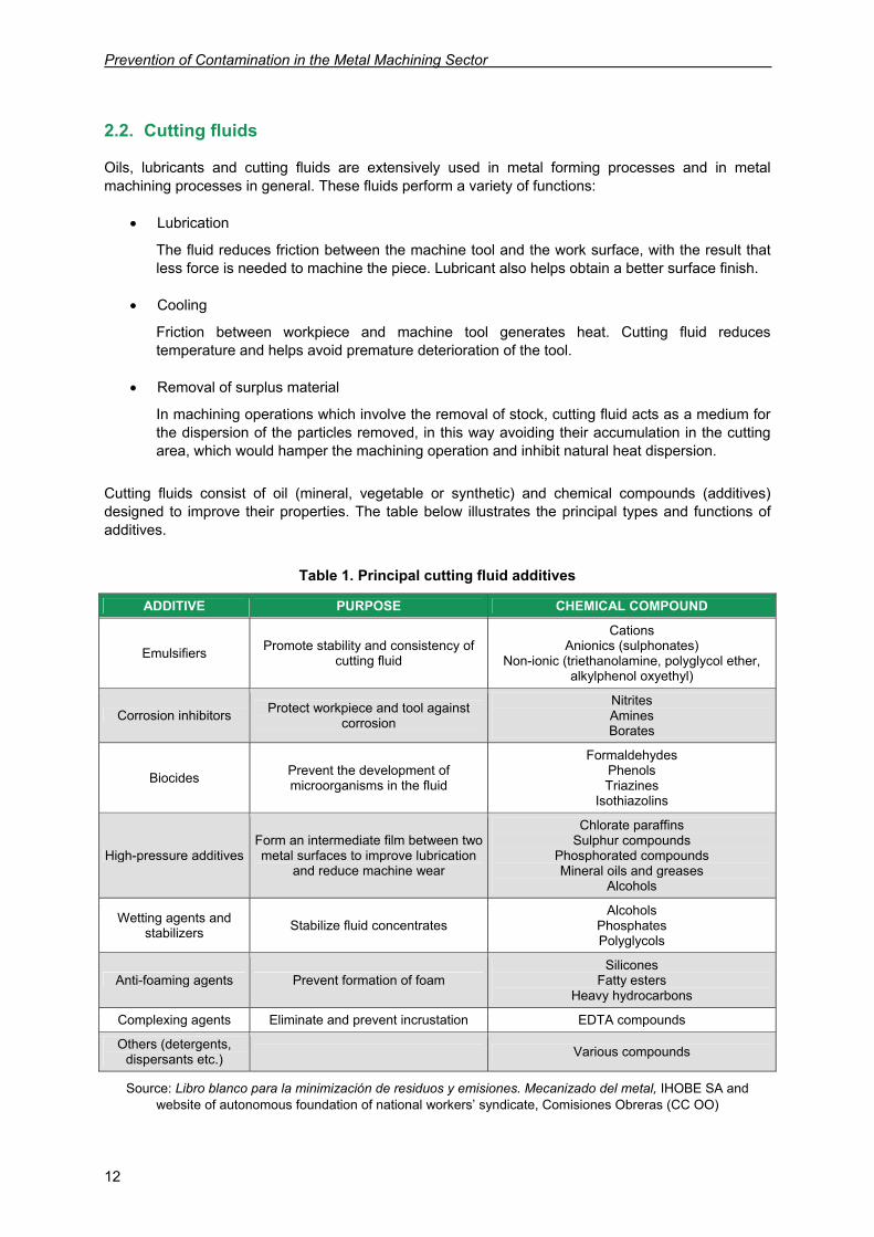
Cutting fluids consist of oil (mineral, vegetable or synthetic) and chemical compounds (additives) designed to improve their properties. The table below illustrates the principal types and functions of additives.
Table 1. Principal cutting fluid additives
ADDITIVE PURPOSE CHEMICAL COMPOUND
Emulsifiers Promote stability and consistency of cutting fluid
Cations Anionics (sulphonates)
Non-ionic (triethanolamine, polyglycol ether, alkylphenol oxyethyl)
Corrosion inhibitors Protect workpiece and tool against corrosion
Nitrites Amines Borates
Biocides Prevent the development of microorganisms in the fluid
Formaldehydes Phenols Triazines
Isothiazolins
High-pressure additives Form an intermediate film between two metal surfaces to improve lubrication
and reduce machine wear
Chlorate paraffins Sulphur compounds
Phosphorated compounds Mineral oils and greases
Alcohols
Wetting agents and stabilizers Stabilize fluid concentrates
Alcohols Phosphates Polyglycols
Anti-foaming agents Prevent formation of foam Silicones
Fatty esters Heavy hydrocarbons
Complexing agents Eliminate and prevent incrustation EDTA compounds
Others (detergents, dispersants etc.) Various compounds
Source: Libro blanco para la minimización de residuos y emisiones. Mecanizado del metal, IHOBE SA and website of autonomous foundation of national workers’ syndicate, Comisiones Obreras (CC OO)
Production processes in the metal machining sector and associated environmental issues
13
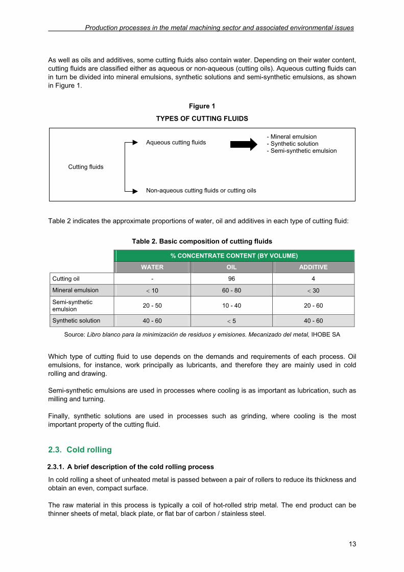
As well as oils and additives, some cutting fluids also contain water. Depending on their water content, cutting fluids are classified either as aqueous or non-aqueous (cutting oils). Aqueous cutting fluids can in turn be divided into mineral emulsions, synthetic solutions and semi-synthetic emulsions, as shown in Figure 1.
Figure 1
TYPES OF CUTTING FLUIDS
Table 2 indicates the approximate proportions of water, oil and additives in each type of cutting fluid:
Table 2. Basic composition of cutting fluids
% CONCENTRATE CONTENT (BY VOLUME)
WATER OIL ADDITIVE
Cutting oil - 96 4
Mineral emulsion < 10 60 - 80 < 30
Semi-synthetic emulsion 20 - 50 10 - 40 20 - 60
Synthetic solution 40 - 60 < 5 40 - 60
Source: Libro blanco para la minimización de residuos y emisiones. Mecanizado del metal, IHOBE SA
Which type of cutting fluid to use depends on the demands and requirements of each process. Oil emulsions, for instance, work principally as lubricants, and therefore they are mainly used in cold rolling and drawing. Semi-synthetic emulsions are used in processes where cooling is as important as lubrication, such as milling and turning. Finally, synthetic solutions are used in processes such as grinding, where cooling is the most important property of the cutting fluid.
2.3. Cold rolling
2.3.1. A brief description of the cold rolling process
In cold rolling a sheet of unheated metal is passed between a pair of rollers to reduce its thickness and obtain an even, compact surface. The raw material in this process is typically a coil of hot-rolled strip metal. The end product can be thinner sheets of metal, black plate, or flat bar of carbon / stainless steel.
Cutting fluids
Aqueous cutting fluids
Non-aqueous cutting fluids or cutting oils
- Mineral emulsion - Synthetic solution - Semi-synthetic emulsion
Prevention of Contamination in the Metal Machining Sector
14
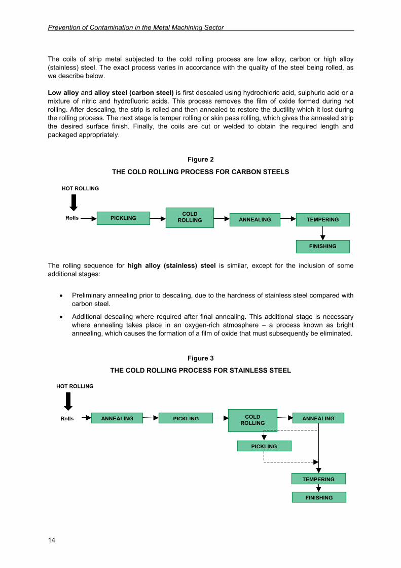
The coils of strip metal subjected to the cold rolling process are low alloy, carbon or high alloy (stainless) steel. The exact process varies in accordance with the quality of the steel being rolled, as we describe below. Low alloy and alloy steel (carbon steel) is first descaled using hydrochloric acid, sulphuric acid or a mixture of nitric and hydrofluoric acids. This process removes the film of oxide formed during hot rolling. After descaling, the strip is rolled and then annealed to restore the ductility which it lost during the rolling process. The next stage is temper rolling or skin pass rolling, which gives the annealed strip the desired surface finish. Finally, the coils are cut or welded to obtain the required length and packaged appropriately.
Figure 2
THE COLD ROLLING PROCESS FOR CARBON STEELS
The rolling sequence for high alloy (stainless) steel is similar, except for the inclusion of some additional stages:
• Preliminary annealing prior to descaling, due to the hardness of stainless steel compared with carbon steel.
• Additional descaling where required after final annealing. This additional stage is necessary where annealing takes place in an oxygen-rich atmosphere – a process known as bright annealing, which causes the formation of a film of oxide that must subsequently be eliminated.
Figure 3
THE COLD ROLLING PROCESS FOR STAINLESS STEEL
HOT ROLLING
Rolls PICKLING
COLD ROLLING
ANNEALING
TEMPERING
FINISHING
ANNEALING
PICKLING
HOT ROLLING
Rolls PICKLING COLD
ROLLING ANNEALING TEMPERING
FINISHING
Production processes in the metal machining sector and associated environmental issues
15
2.3.2. Cold rolling and environmental considerations
Two methods are used in the cold rolling process. The first consists of feeding the strip through reversible trains, with the work passed backwards and forwards through the rollers until the desired thickness is obtained. This process is known as semi-continuous rolling. The second method uses a succession of rollers through which the strip passes once only, emerging thinner from each pair of rollers until the desired thickness is obtained. When carbon steel is being rolled, if the carbon content is low the continuous rolling method is used. In practice, multistand or tandem rolling mills are used for this operation, as their production capacity is higher. Each stand comprises an array of between four and six superimposed sets of rollers. The strips are fed in a continuous sequence through each stand, their section reducing each time until the desired thickness has been obtained. Other varieties of carbon steel can be batch processed, with a single assembly with various rolls through which the strip is passed back and forward several times. In the latter case, the strip has to be fed back into the roller at every pass. The principal environmental issue in the rolling of strip containing carbon steel is the use of an oil-water emulsion with oil content of 0.5 to 4% for lubricating, cooling machine and workpiece, and eliminating iron particles. This emulsion is a mixture of rolling oil and de-mineralized water. In batch rolling, the emulsion is applied via spray nozzles located above the rollers through which the strip passes. In continuous rolling, various independent emulsion systems can be used. This makes it possible, for instance, to apply a special cleaning emulsion at the final stand. This special emulsion might contain a detergent or have an extra-low oil content in the order of approximately 1%. Special precautions have to be taken to prevent contamination of emulsions by machine oils, grease or cooling water so that strip surfaces are perfectly clean at all times. These precautions include, among others, regular inspections of hydraulic fittings and machine bearings, and monitoring of emulsion properties such as pH, saponification index, acid concentration etc. The use of these emulsions produces waste water which may contain oils or solids in suspension. This waste water has to be treated in emulsion breaking plants. The end product of these plants is oil sludge. Cold rolling requires energy. This energy is usually in the form of electricity, although some tandem rolling mills with emulsion systems can also use steam power to heat the emulsions. Other kinds of waste, such as dust, hydrocarbons and oil particles, are also produced as a result of the cold rolling process.
Prevention of Contamination in the Metal Machining Sector
16
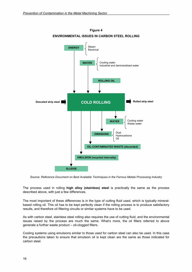
Figure 4
ENVIRONMENTAL ISSUES IN CARBON STEEL ROLLING
Source: Reference Document on Best Available Techniques in the Ferrous Metals Processing Industry
The process used in rolling high alloy (stainless) steel is practically the same as the process described above, with just a few differences. The most important of these differences is in the type of cutting fluid used, which is typically mineral-based rolling oil. This oil has to be kept perfectly clean if the rolling process is to produce satisfactory results, and therefore oil filtering circuits or similar systems have to be used. As with carbon steel, stainless steel rolling also requires the use of cutting fluid, and the environmental issues raised by the process are much the same. What’s more, the oil filters referred to above generate a further waste product – oil-clogged filters. Cooling systems using emulsions similar to those used for carbon steel can also be used. In this case the precautions taken to ensure that emulsion oil is kept clean are the same as those indicated for carbon steel.
COLD ROLLING
Descaled strip steel
ENERGY
WATER
ROLLING OIL
Steam Electrical
Cooling water Industrial and demineralized water
Rolled strip steel
WATER
Cooling water Waste water
EMISSIONS
Dust Hydrocarbons Oil
OIL-CONTAMINATED WASTE (discarded)
EMULSION (recycled internally)
SLUDGE
Production processes in the metal machining sector and associated environmental issues
17
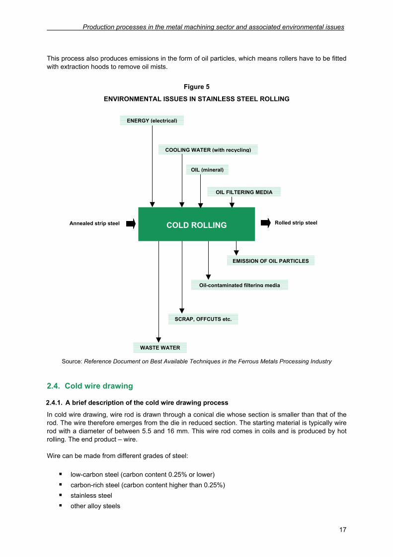
This process also produces emissions in the form of oil particles, which means rollers have to be fitted with extraction hoods to remove oil mists.
Figure 5
ENVIRONMENTAL ISSUES IN STAINLESS STEEL ROLLING
Source: Reference Document on Best Available Techniques in the Ferrous Metals Processing Industry
2.4. Cold wire drawing
2.4.1. A brief description of the cold wire drawing process
In cold wire drawing, wire rod is drawn through a conical die whose section is smaller than that of the rod. The wire therefore emerges from the die in reduced section. The starting material is typically wire rod with a diameter of between 5.5 and 16 mm. This wire rod comes in coils and is produced by hot rolling. The end product – wire. Wire can be made from different grades of steel: low-carbon steel (carbon content 0.25% or lower) carbon-rich steel (carbon content higher than 0.25%) stainless steel other alloy steels
Annealed strip steel
ENERGY (electrical)
COOLING WATER (with recycling)
OIL (mineral)
Rolled strip steel
EMISSION OF OIL PARTICLES
Oil-contaminated filtering media
SCRAP, OFFCUTS etc.
WASTE WATER
COLD ROLLING
OIL FILTERING MEDIA
Prevention of Contamination in the Metal Machining Sector
18
Depending on which type of steel is used, the wire obtained is used for making a wide variety of products: springs, piano wire, fencing, mesh etc. The stages followed in the wire drawing process are similar to those used in the cold rolling process:
Pre-treatment of wire rod (scalebreaking, descaling) Drawing Heat treatment (continuous/batch annealing, quenching, patenting, oil quenching) Finishing (surface coating)
2.4.2. Cold wire drawing and environmental considerations
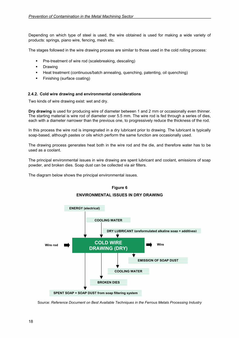
Two kinds of wire drawing exist: wet and dry. Dry drawing is used for producing wire of diameter between 1 and 2 mm or occasionally even thinner. The starting material is wire rod of diameter over 5.5 mm. The wire rod is fed through a series of dies, each with a diameter narrower than the previous one, to progressively reduce the thickness of the rod. In this process the wire rod is impregnated in a dry lubricant prior to drawing. The lubricant is typically soap-based, although pastes or oils which perform the same function are occasionally used. The drawing process generates heat both in the wire rod and the die, and therefore water has to be used as a coolant. The principal environmental issues in wire drawing are spent lubricant and coolant, emissions of soap powder, and broken dies. Soap dust can be collected via air filters. The diagram below shows the principal environmental issues.
Figure 6
ENVIRONMENTAL ISSUES IN DRY DRAWING
Source: Reference Document on Best Available Techniques in the Ferrous Metals Processing Industry
Wire rod
ENERGY (electrical)
COOLING WATER
DRY LUBRICANT (preformulated alkaline soap + additives)
Wire
EMISSION OF SOAP DUST
COOLING WATER
BROKEN DIES
SPENT SOAP + SOAP DUST from soap filtering system
COLD WIRE DRAWING (DRY)
Production processes in the metal machining sector and associated environmental issues
19
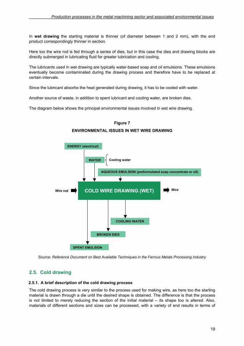
In wet drawing the starting material is thinner (of diameter between 1 and 2 mm), with the end product correspondingly thinner in section. Here too the wire rod is fed through a series of dies, but in this case the dies and drawing blocks are directly submerged in lubricating fluid for greater lubrication and cooling. The lubricants used in wet drawing are typically water-based soap and oil emulsions. These emulsions eventually become contaminated during the drawing process and therefore have to be replaced at certain intervals. Since the lubricant absorbs the heat generated during drawing, it has to be cooled with water. Another source of waste, in addition to spent lubricant and cooling water, are broken dies. The diagram below shows the principal environmental issues involved in wet wire drawing.
Figure 7
ENVIRONMENTAL ISSUES IN WET WIRE DRAWING
Source: Reference Document on Best Available Techniques in the Ferrous Metals Processing Industry
2.5. Cold drawing
2.5.1. A brief description of the cold drawing process
The cold drawing process is very similar to the process used for making wire, as here too the starting material is drawn through a die until the desired shape is obtained. The difference is that the process is not limited to merely reducing the section of the initial material – its shape too is altered. Also, materials of different sections and sizes can be processed, with a variety of end results in terms of
Wire rod
ENERGY (electrical)
WATER
AQUEOUS EMULSION (preformulated soap concentrate or oil)
Wire
COOLING WATER
BROKEN DIES
SPENT EMULSION
COLD WIRE DRAWING (WET)
Cooling water
Prevention of Contamination in the Metal Machining Sector
20
shape and dimensions. Wire drawing, on the other hand, works exclusively with wire rod, the workpiece being circular in section at all stages of the process. The starting material is steel bars which have previously been hot-rolled. The end product of the drawing process is a polished steel bar of certain shape and characteristics; its cross section is typically square, rectangular or hexagonal, although other sections can be produced where required. Each type of section can be put to various uses. For instance, bars of hexagonal section can be used in making screws and nuts. The bar is normally cut crosswise to produce individual pieces. The products formed in this way are used in the automobile industry, machinery, construction, electrical apparatus and other sectors where a high quality of material is required. The drawing process follows a similar sequence to wire drawing. First the metal is descaled to eliminate surface oxides and impurities. Then drawing proper begins. This process hardens the steel and increases its tensile strength, while reducing its ductility. Therefore, depending on the end product to be obtained, cold drawn steel has to be annealed afterwards. In the final stage of the process the steel is finished by skin passing and polishing, and its end point is cut off.
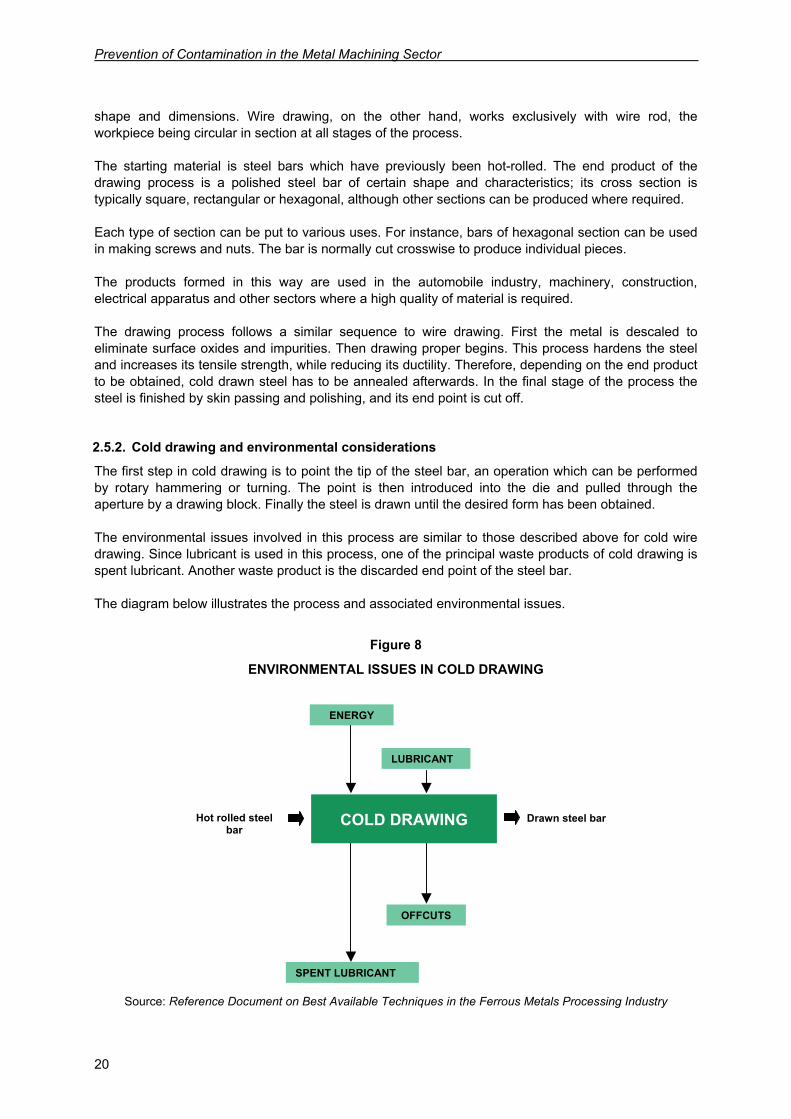
2.5.2. Cold drawing and environmental considerations
The first step in cold drawing is to point the tip of the steel bar, an operation which can be performed by rotary hammering or turning. The point is then introduced into the die and pulled through the aperture by a drawing block. Finally the steel is drawn until the desired form has been obtained. The environmental issues involved in this process are similar to those described above for cold wire drawing. Since lubricant is used in this process, one of the principal waste products of cold drawing is spent lubricant. Another waste product is the discarded end point of the steel bar. The diagram below illustrates the process and associated environmental issues.
Figure 8
ENVIRONMENTAL ISSUES IN COLD DRAWING
Source: Reference Document on Best Available Techniques in the Ferrous Metals Processing Industry
Hot rolled steel bar
ENERGY
LUBRICANT
Drawn steel bar
OFFCUTS
SPENT LUBRICANT
COLD DRAWING
Production processes in the metal machining sector and associated environmental issues
21
2.6. Punching and deep drawing
2.6.1. A brief description of the punching and deep drawing processes
In this section we examine the punching and deep drawing processes jointly, given the similarities in the sequence of operations followed by each process and the tools used; the purpose of each technique, of course, is different. In deep drawing the starting material is deformed by a mould or stamp (punch and die) to produce a hollow body without altering its initial thickness. The starting material is a flat disk or platelet of iron, aluminium or brass. The end product is simply the same disk or platelet deformed into a concave or bombé shape. Unlike punching, in deep drawing no part of the workpiece is cut off or punched out. In the deep drawing of sheet iron, the iron must first be annealed and then reheated after drawing to eliminate any internal stresses. In punching, the sheet of metal is perforated using a punch and die assembly. The punch is mounted on a rocker arm and cuts by pressure. Where the cut-out piece is the piece to be used, the process is known as cutting out. Where the cut-out piece is discarded – i.e. the workpiece is perforated – the process is known as punching. In both cases, the finished product is smaller than the original workpiece. In this type of metal forming the thickness of the sheet remains unchanged except in cases where an imprint is made on the metal. This process is called coining, after its similarity to the process used in striking coins.
2.6.2. Punching, deep drawing and environmental issues
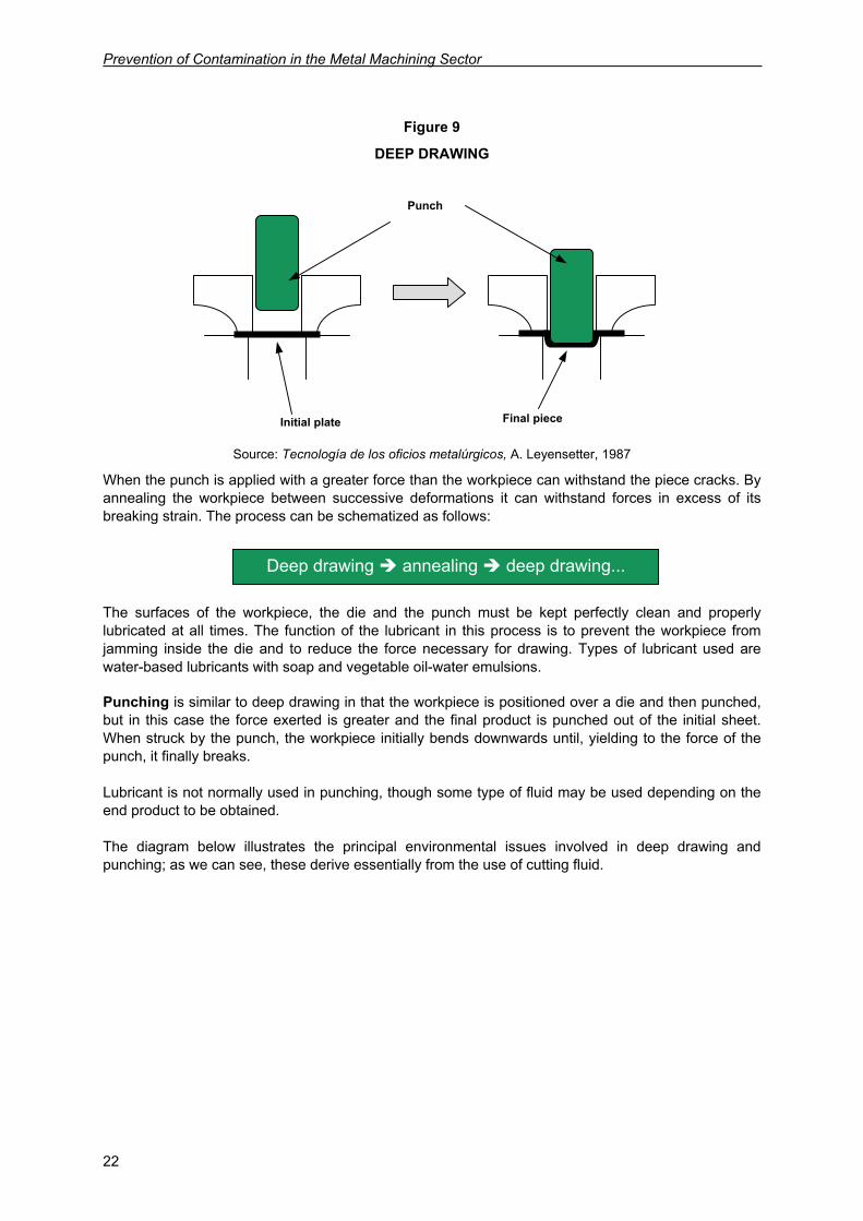
In deep drawing, the workpiece is placed between the punch and the die, which is slightly thicker than the sheet to be drawn. The punch is forced downwards to press the workpiece into the die, in this way deforming the sheet without breaking it. Once deformed, the punch retracts and the workpiece is spring-ejected. The deep drawing process is illustrated in the diagram below.
Prevention of Contamination in the Metal Machining Sector
22
Figure 9
DEEP DRAWING
Source: Tecnología de los oficios metalúrgicos, A. Leyensetter, 1987
When the punch is applied with a greater force than the workpiece can withstand the piece cracks. By annealing the workpiece between successive deformations it can withstand forces in excess of its breaking strain. The process can be schematized as follows:
The surfaces of the workpiece, the die and the punch must be kept perfectly clean and properly lubricated at all times. The function of the lubricant in this process is to prevent the workpiece from jamming inside the die and to reduce the force necessary for drawing. Types of lubricant used are water-based lubricants with soap and vegetable oil-water emulsions. Punching is similar to deep drawing in that the workpiece is positioned over a die and then punched, but in this case the force exerted is greater and the final product is punched out of the initial sheet. When struck by the punch, the workpiece initially bends downwards until, yielding to the force of the punch, it finally breaks. Lubricant is not normally used in punching, though some type of fluid may be used depending on the end product to be obtained. The diagram below illustrates the principal environmental issues involved in deep drawing and punching; as we can see, these derive essentially from the use of cutting fluid.
Deep drawing annealing deep drawing...
Punch
Initial plate Final piece
Production processes in the metal machining sector and associated environmental issues
23
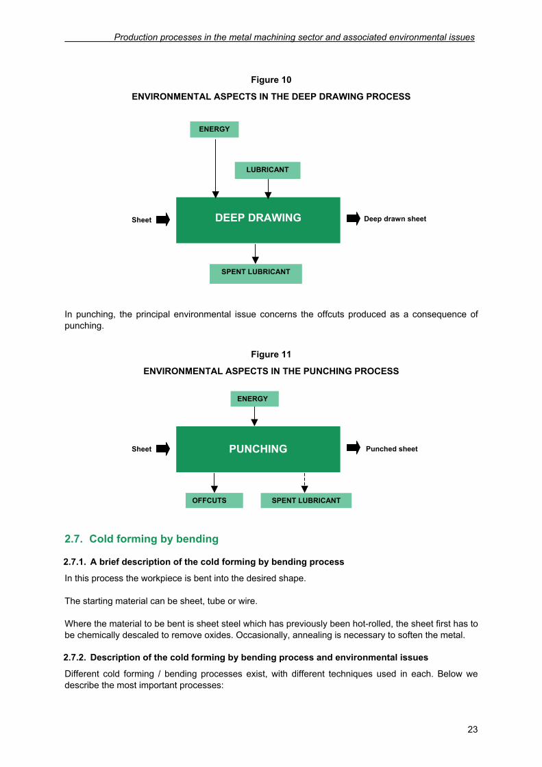
Figure 10
ENVIRONMENTAL ASPECTS IN THE DEEP DRAWING PROCESS
In punching, the principal environmental issue concerns the offcuts produced as a consequence of punching.
Figure 11
ENVIRONMENTAL ASPECTS IN THE PUNCHING PROCESS
2.7. Cold forming by bending
2.7.1. A brief description of the cold forming by bending process
In this process the workpiece is bent into the desired shape. The starting material can be sheet, tube or wire. Where the material to be bent is sheet steel which has previously been hot-rolled, the sheet first has to be chemically descaled to remove oxides. Occasionally, annealing is necessary to soften the metal.
2.7.2. Description of the cold forming by bending process and environmental issues
Different cold forming / bending processes exist, with different techniques used in each. Below we describe the most important processes:
Sheet
ENERGY
LUBRICANT
Deep drawn sheet
SPENT LUBRICANT
DEEP DRAWING
Sheet
ENERGY
Punched sheet
PUNCHING
OFFCUTS SPENT LUBRICANT
Prevention of Contamination in the Metal Machining Sector
24
Free bending
In this process the workpiece is shaped by manual folding or with the help of a vice. In tube forming, the tube first has to be filled or a special guide used to prevent flattening at the bend.
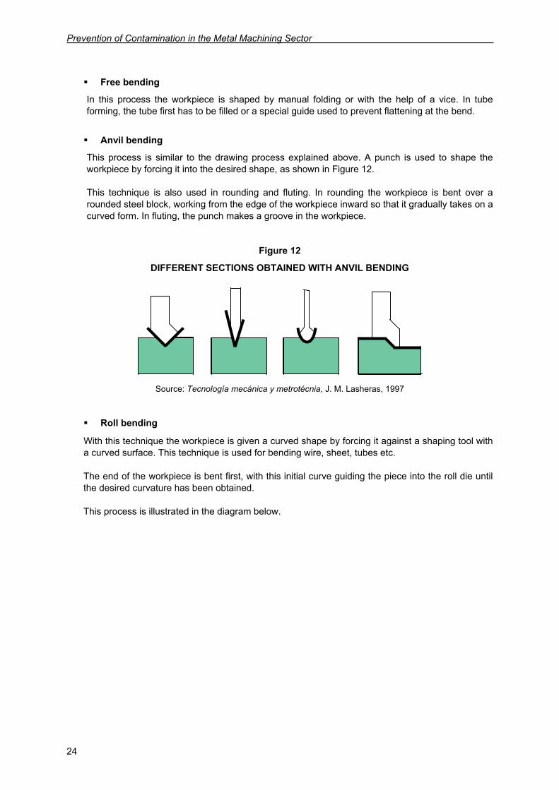
Anvil bending
This process is similar to the drawing process explained above. A punch is used to shape the workpiece by forcing it into the desired shape, as shown in Figure 12. This technique is also used in rounding and fluting. In rounding the workpiece is bent over a rounded steel block, working from the edge of the workpiece inward so that it gradually takes on a curved form. In fluting, the punch makes a groove in the workpiece.
Figure 12
DIFFERENT SECTIONS OBTAINED WITH ANVIL BENDING
Source: Tecnología mecánica y metrotécnia, J. M. Lasheras, 1997
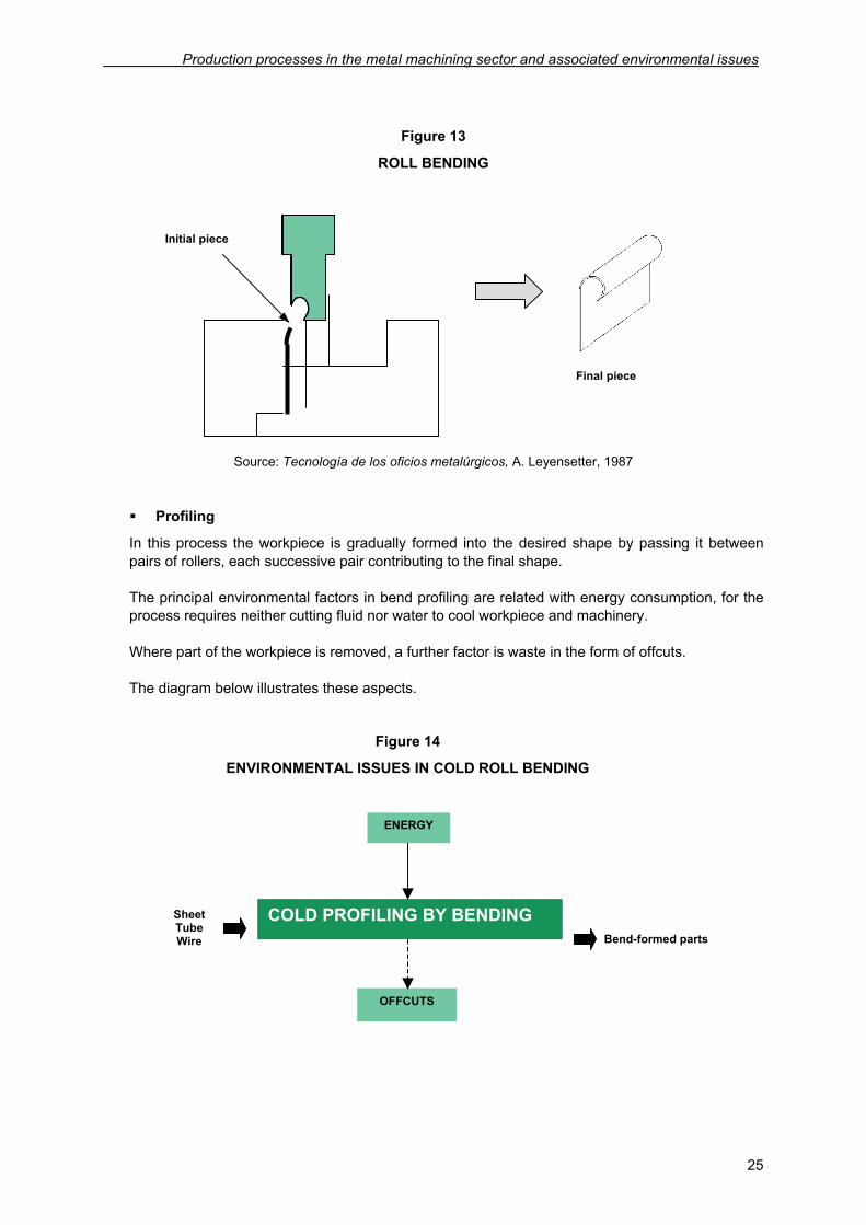
Roll bending
With this technique the workpiece is given a curved shape by forcing it against a shaping tool with a curved surface. This technique is used for bending wire, sheet, tubes etc. The end of the workpiece is bent first, with this initial curve guiding the piece into the roll die until the desired curvature has been obtained. This process is illustrated in the diagram below.
Production processes in the metal machining sector and associated environmental issues
25
Figure 13
ROLL BENDING
Source: Tecnología de los oficios metalúrgicos, A. Leyensetter, 1987
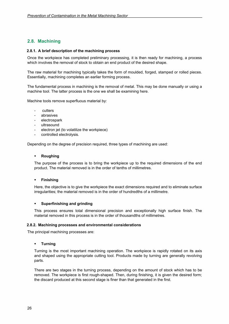
Profiling
In this process the workpiece is gradually formed into the desired shape by passing it between pairs of rollers, each successive pair contributing to the final shape. The principal environmental factors in bend profiling are related with energy consumption, for the process requires neither cutting fluid nor water to cool workpiece and machinery. Where part of the workpiece is removed, a further factor is waste in the form of offcuts. The diagram below illustrates these aspects.
Figure 14
ENVIRONMENTAL ISSUES IN COLD ROLL BENDING
Final piece
Initial piece
Sheet Tube Wire
ENERGY
Bend-formed parts
COLD PROFILING BY BENDING
OFFCUTS
Prevention of Contamination in the Metal Machining Sector
26
2.8. Machining
2.8.1. A brief description of the machining process
Once the workpiece has completed preliminary processing, it is then ready for machining, a process which involves the removal of stock to obtain an end product of the desired shape. The raw material for machining typically takes the form of moulded, forged, stamped or rolled pieces. Essentially, machining completes an earlier forming process. The fundamental process in machining is the removal of metal. This may be done manually or using a machine tool. The latter process is the one we shall be examining here. Machine tools remove superfluous material by:
- cutters - abrasives - electrospark - ultrasound - electron jet (to volatilize the workpiece) - controlled electrolysis.
Depending on the degree of precision required, three types of machining are used:
Roughing
The purpose of the process is to bring the workpiece up to the required dimensions of the end product. The material removed is in the order of tenths of millimetres.
Finishing
Here, the objective is to give the workpiece the exact dimensions required and to eliminate surface irregularities; the material removed is in the order of hundredths of a millimetre.
Superfinishing and grinding
This process ensures total dimensional precision and exceptionally high surface finish. The material removed in this process is in the order of thousandths of millimetres.
2.8.2. Machining processes and environmental considerations
The principal machining processes are:
Turning
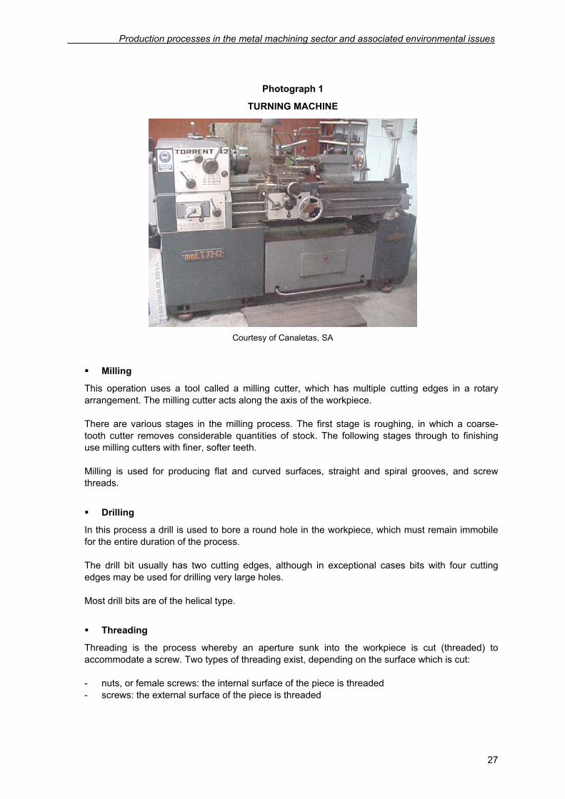
Turning is the most important machining operation. The workpiece is rapidly rotated on its axis and shaped using the appropriate cutting tool. Products made by turning are generally revolving parts. There are two stages in the turning process, depending on the amount of stock which has to be removed. The workpiece is first rough-shaped. Then, during finishing, it is given the desired form; the discard produced at this second stage is finer than that generated in the first.
Production processes in the metal machining sector and associated environmental issues
27
Photograph 1
TURNING MACHINE
Courtesy of Canaletas, SA
Milling
This operation uses a tool called a milling cutter, which has multiple cutting edges in a rotary arrangement. The milling cutter acts along the axis of the workpiece. There are various stages in the milling process. The first stage is roughing, in which a coarse-tooth cutter removes considerable quantities of stock. The following stages through to finishing use milling cutters with finer, softer teeth. Milling is used for producing flat and curved surfaces, straight and spiral grooves, and screw threads.
Drilling
In this process a drill is used to bore a round hole in the workpiece, which must remain immobile for the entire duration of the process. The drill bit usually has two cutting edges, although in exceptional cases bits with four cutting edges may be used for drilling very large holes. Most drill bits are of the helical type.
Threading
Threading is the process whereby an aperture sunk into the workpiece is cut (threaded) to accommodate a screw. Two types of threading exist, depending on the surface which is cut: - nuts, or female screws: the internal surface of the piece is threaded - screws: the external surface of the piece is threaded
Prevention of Contamination in the Metal Machining Sector
28
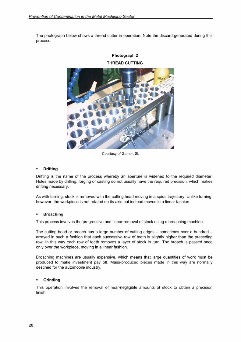
The photograph below shows a thread cutter in operation. Note the discard generated during this process.
Photograph 2
THREAD CUTTING
Courtesy of Gamor, SL
Drifting
Drifting is the name of the process whereby an aperture is widened to the required diameter. Holes made by drilling, forging or casting do not usually have the required precision, which makes drifting necessary. As with turning, stock is removed with the cutting head moving in a spiral trajectory. Unlike turning, however, the workpiece is not rotated on its axis but instead moves in a linear fashion.
Broaching
This process involves the progressive and linear removal of stock using a broaching machine. The cutting head or broach has a large number of cutting edges – sometimes over a hundred – arrayed in such a fashion that each successive row of teeth is slightly higher than the preceding row. In this way each row of teeth removes a layer of stock in turn. The broach is passed once only over the workpiece, moving in a linear fashion. Broaching machines are usually expensive, which means that large quantities of work must be produced to make investment pay off. Mass-produced pieces made in this way are normally destined for the automobile industry.
Grinding
This operation involves the removal of near-negligible amounts of stock to obtain a precision finish.
Production processes in the metal machining sector and associated environmental issues
29
The tool used in this process is called a grinding wheel. It has two principal components. The first is the abrasive element, a small high-durability crystal which performs the grinding. The other part is the binder, which holds the abrasive in place while giving it extra resistance. Grinding is the primary abrasive-based machining process, although other processes, such as flash removal, polishing and honing, use similar techniques.
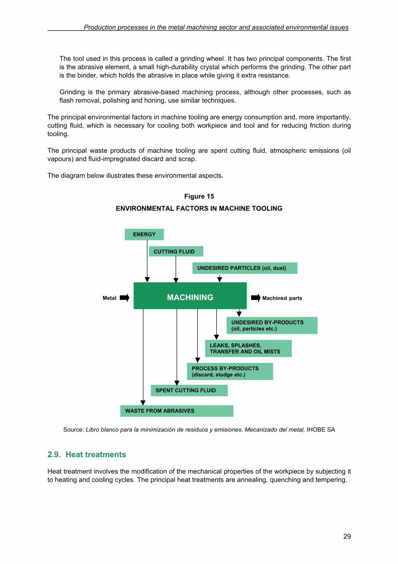
The principal environmental factors in machine tooling are energy consumption and, more importantly, cutting fluid, which is necessary for cooling both workpiece and tool and for reducing friction during tooling. The principal waste products of machine tooling are spent cutting fluid, atmospheric emissions (oil vapours) and fluid-impregnated discard and scrap. The diagram below illustrates these environmental aspects.
Figure 15
ENVIRONMENTAL FACTORS IN MACHINE TOOLING
Source: Libro blanco para la minimización de residuos y emisiones. Mecanizado del metal, IHOBE SA
2.9. Heat treatments
Heat treatment involves the modification of the mechanical properties of the workpiece by subjecting it to heating and cooling cycles. The principal heat treatments are annealing, quenching and tempering.
Metal
ENERGY
CUTTING FLUID
Machined parts
UNDESIRED BY-PRODUCTS (oil, particles etc.)
MACHINING
UNDESIRED PARTICLES (oil, dust)
SPENT CUTTING FLUID
LEAKS, SPLASHES, TRANSFER AND OIL MISTS
PROCESS BY-PRODUCTS (discard, sludge etc.)
WASTE FROM ABRASIVES
Prevention of Contamination in the Metal Machining Sector
30
2.9.1. Annealing
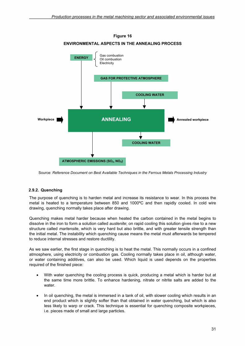
Annealing involves heating the workpiece to a temperature in the range of 800 to 925ºC, depending on the carbon content of the steel, followed by slow cooling. Annealing increases the ductility of the metal while it also makes it softer. This makes annealing appropriate for workpieces which are to drawn or machined, as they are then easier to shape. Annealing also promotes even grain alignment of the steel. Cold processes such as rolling, drawing and, on occasion, bending are usually followed by annealing to eliminate the asperity and internal stresses produced during cold processing. In these cases a special type of stress elimination annealing is carried out. In this process, the steel is heated to a temperature in the region of 500ºC, although in some cases, depending on the composition of the steel, this temperature may be as high as 700ºC. This process restores softness and ductility to the workpiece after deformation of its crystal structure during drawing. This type of annealing is occasionally performed in an enclosed furnace filled with inert gas to prevent surface oxidation. This process is known as bright annealing. The process takes place in an electrically- or fuel-powered annealing furnace. The nitrogen or inert-gas atmosphere inside the furnace prevents surface reactions with the steel. The process lasts approximately four hours. Annealing is followed by cooling. The slower the cooling, the more ductile the end product, but in general cooling takes around forty-eight hours. Cooling may take place inside the furnace itself, with the metal covered in dry sand, ash or lime, or in the open air. In-furnace cooling can be improved by spraying the furnace cover with water, feeding air into the furnace or using a cooling system which reduces ambient temperature. The principal environmental issues involved in the annealing process are energy consumption and the emissions generated by gas combustion. Where water is used to speed the cooling process, waste water is also generated. The table below summarizes these factors.
Production processes in the metal machining sector and associated environmental issues
31
Figure 16
ENVIRONMENTAL ASPECTS IN THE ANNEALING PROCESS
Source: Reference Document on Best Available Techniques in the Ferrous Metals Processing Industry
2.9.2. Quenching
The purpose of quenching is to harden metal and increase its resistance to wear. In this process the metal is heated to a temperature between 850 and 1000ºC and then rapidly cooled. In cold wire drawing, quenching normally takes place after drawing. Quenching makes metal harder because when heated the carbon contained in the metal begins to dissolve in the iron to form a solution called austenite; on rapid cooling this solution gives rise to a new structure called martensite, which is very hard but also brittle, and with greater tensile strength than the initial metal. The instability which quenching cause means the metal must afterwards be tempered to reduce internal stresses and restore ductility. As we saw earlier, the first stage in quenching is to heat the metal. This normally occurs in a confined atmosphere, using electricity or combustion gas. Cooling normally takes place in oil, although water, or water containing additives, can also be used. Which liquid is used depends on the properties required of the finished piece:
• With water quenching the cooling process is quick, producing a metal which is harder but at the same time more brittle. To enhance hardening, nitrate or nitrite salts are added to the water.
• In oil quenching, the metal is immersed in a tank of oil, with slower cooling which results in an
end product which is slightly softer than that obtained in water quenching, but which is also less likely to warp or crack. This technique is essential for quenching composite workpieces, i.e. pieces made of small and large particles.
ANNEALING Workpiece
ENERGY
Annealed workpiece
ATMOSPHERIC EMISSIONS (SO2, NOX)
COOLING WATER
Gas combustion Oil combustion Electricity
COOLING WATER
GAS FOR PROTECTIVE ATMOSPHERE
Prevention of Contamination in the Metal Machining Sector
32
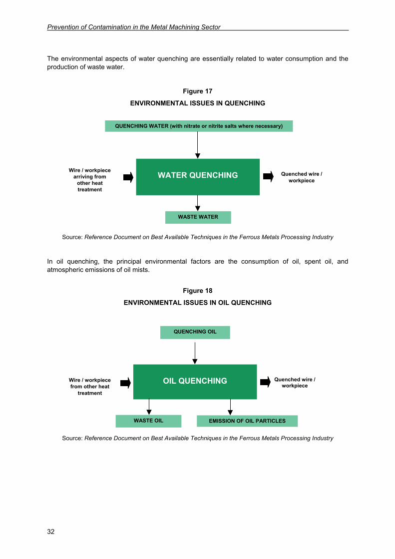
The environmental aspects of water quenching are essentially related to water consumption and the production of waste water.
Figure 17
ENVIRONMENTAL ISSUES IN QUENCHING
Source: Reference Document on Best Available Techniques in the Ferrous Metals Processing Industry
In oil quenching, the principal environmental factors are the consumption of oil, spent oil, and atmospheric emissions of oil mists.
Figure 18
ENVIRONMENTAL ISSUES IN OIL QUENCHING
Source: Reference Document on Best Available Techniques in the Ferrous Metals Processing Industry
WATER QUENCHING
Wire / workpiece arriving from
other heat treatment
QUENCHING WATER (with nitrate or nitrite salts where necessary)
Quenched wire / workpiece
WASTE WATER
OIL QUENCHING
QUENCHING OIL
WASTE OIL EMISSION OF OIL PARTICLES
Wire / workpiece from other heat
treatment
Quenched wire / workpiece
Production processes in the metal machining sector and associated environmental issues
33
2.9.3. Tempering
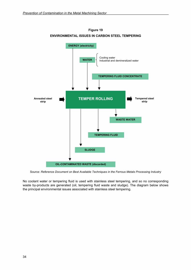
Tempering is a routine process for workpieces which have previously been quenched. Its objective is to reduce the hardness produced by quenching and eliminate internal stresses to produce a tougher metal. Tempering consists of heating the piece to a temperature known as the tempering point, which can vary depending on the desired resistance and ductility of the piece. The piece is then cooled in air, water or, in some processes, oil, fused electrolyte or metal solution. In cold wire drawing, tempering occurs immediately after quenching. In this particular process the wire is heated to a temperature of between 300 and 500°C in an oven powered by electricity or by direct gas combustion. Induction heating may also be used. Another forming process in which tempering is an essential stage is cold rolling. Here a special technique known as temper rolling is used, in which the strip of rolled metal is skin-passed through tempering trains to reduce its thickness by 0.3 - 2%. The purpose of this operation is to improve the mechanical properties of the steel and obtain a satisfactory surface finish. The starting material in this process is strip steel which has previously been annealed. The end product is smoother, with a better surface finish. The strip enters the stand at a temperature below 50°C. The roll stand normally comprises one or two sets of four superimposed rollers, although two- or six-high arrays are also used. The rollers and cylinders have exceptionally smooth surfaces to prevent irregularities in the steel strip. Stainless steel is normally dry-tempered, without application of cooling oil or water. In carbon steel tempering, however, a coolant solution with 5% content of wet temper rolling agent is used to eliminate any process residue from the strip. This process requires electrical energy to power the rolling trains and hydraulic system. These environmental factors are summarized in the table below.
Prevention of Contamination in the Metal Machining Sector
34
Figure 19
ENVIRONMENTAL ISSUES IN CARBON STEEL TEMPERING
Source: Reference Document on Best Available Techniques in the Ferrous Metals Processing Industry
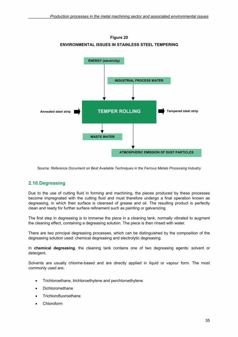
No coolant water or tempering fluid is used with stainless steel tempering, and so no corresponding waste by-products are generated (oil, tempering fluid waste and sludge). The diagram below shows the principal environmental issues associated with stainless steel tempering.
TEMPER ROLLING Annealed steel
strip
ENERGY (electricity)
WATER
TEMPERING FLUID CONCENTRATE
Cooling water Industrial and demineralized water
Tempered steel strip
WASTE WATER
OIL-CONTAMINATED WASTE (discarded)
TEMPERING FLUID
SLUDGE
Production processes in the metal machining sector and associated environmental issues
35
Figure 20
ENVIRONMENTAL ISSUES IN STAINLESS STEEL TEMPERING
Source: Reference Document on Best Available Techniques in the Ferrous Metals Processing Industry
2.10. Degreasing
Due to the use of cutting fluid in forming and machining, the pieces produced by these processes become impregnated with the cutting fluid and must therefore undergo a final operation known as degreasing, in which their surface is cleansed of grease and oil. The resulting product is perfectly clean and ready for further surface refinement such as painting or galvanizing. The first step in degreasing is to immerse the piece in a cleaning tank, normally vibrated to augment the cleaning effect, containing a degreasing solution. The piece is then rinsed with water. There are two principal degreasing processes, which can be distinguished by the composition of the degreasing solution used: chemical degreasing and electrolytic degreasing. In chemical degreasing, the cleaning tank contains one of two degreasing agents: solvent or detergent. Solvents are usually chlorine-based and are directly applied in liquid or vapour form. The most commonly used are:
• Trichloroethane, trichloroethylene and perchloroethylene
• Dichloromethane
• Trichlorofluoroethane
• Chloroform
TEMPER ROLLING
Annealed steel strip
ENERGY (electricity)
INDUSTRIAL PROCESS WATER
Tempered steel strip
WASTE WATER
ATMOSPHERIC EMISSION OF DUST PARTICLES
Prevention of Contamination in the Metal Machining Sector
36
In detergent degreasing an alkaline medium is used. Oil and grease deposits are eliminated from the surface of the piece by the surfactants contained in the detergent. The medium is typically composed of the following substances:
• Caustic soda
• Sodium carbonate
• Trisodium phosphate 12·H2O
• Sodium metasilicate 5·H2O
• Wetting agents
• Metal complexes
In the other method, electrolytic degreasing, the piece is immersed in an alkaline electrolyte solution. The particles present in this solution attack the grease accumulated on the surface of the piece, which acts as a cathode to liberate surface grease which dissolves in the degreasing solution. This process generates metal oxides as a result of the reduction caused by hydrogen particles. The alkaline solution principally comprises:
• Caustic soda
• Trisodium phosphate 12·H2O
• Sodium gluconate
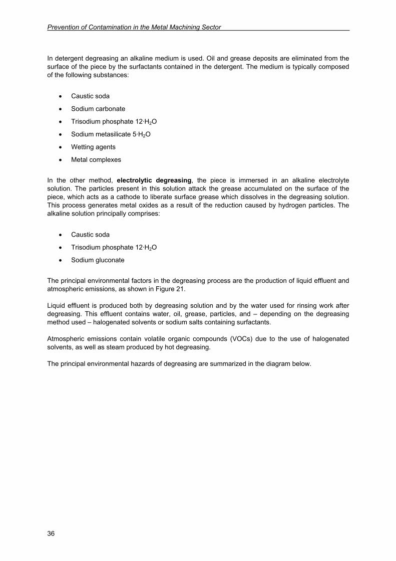
The principal environmental factors in the degreasing process are the production of liquid effluent and atmospheric emissions, as shown in Figure 21. Liquid effluent is produced both by degreasing solution and by the water used for rinsing work after degreasing. This effluent contains water, oil, grease, particles, and – depending on the degreasing method used – halogenated solvents or sodium salts containing surfactants. Atmospheric emissions contain volatile organic compounds (VOCs) due to the use of halogenated solvents, as well as steam produced by hot degreasing. The principal environmental hazards of degreasing are summarized in the diagram below.
Production processes in the metal machining sector and associated environmental issues
37
Figure 21
ENVIRONMENTAL ASPECTS IN DEGREASING
Source: Reference Document on Best Available Techniques in the Ferrous Metals Processing Industry
DEGREASING Workpiece
ENERGY
WATER
Clean workpiece
LIQUID WASTE
ATMOSPHERIC EMISSIONS
CLEANING AGENTS (solvents, detergents, alkaline solutions)

39
3. ENVIRONMENTAL HAZARDS IN THE METAL
MACHINING SECTOR
The environmental issues addressed in this section are water and energy consumption, liquid waste, solid waste, and atmospheric emissions involved in or produced by the processes described in section 2 of this manual. Noise is another aspect that must be considered.
3.1. Water consumption
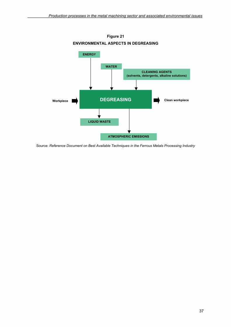
Water consumption in the metal machining sector can vary greatly from one plant to another depending on the scale and nature of the machining operation. Water is principally taken from the public mains, although demineralised water is also used in lesser proportions for the preparation of aqueous cutting fluids. Most of the water is used for cleaning and cooling purposes; the rest goes on auxiliary operations such as line and floor cleaning as well as the industrial process per se. The pie chart below provides a breakdown of water consumption by a company in the metal machining sector. The company also operates a garden and kitchen on the same premises.
Figure 22
WATER CONSUMPTION BY A METAL MACHINING COMPANY (EXAMPLE)
35%
1%5%43%
14%2%
Cooling
Process
Floor cleaning
Sanitary
Irrigation
Kitchen
Source: Data provided by Componentes Mecánicos, SA
As the example shows, water consumption in this sector is not high, since most water is used for purposes common to any type of company: sanitary and cooling. As for the water used in forming processes, it is essentially used in:
Prevention of Contamination in the Metal Machining Sector
40
• Preparation of oil emulsions
Processes such as cold rolling, drawing, drilling and milling, which do use water-based cutting fluid, although the fluid is prepared using demineralised water.
• Heat treatment
In heat treatments such as annealing, quenching and tempering, water is occasionally used for cooling purposes.
• Degreasing
Water is used in cleaning and degreasing workpieces which have become impregnated with grease as a result of the extensive use of cutting fluids in common machining operations and in processes such as oil quenching.
• Process cooling
Processes which involve an increase in temperature require water to cool transformers, engines and machinery in general, and to dissipate the thermal load accumulated by cutting fluid.
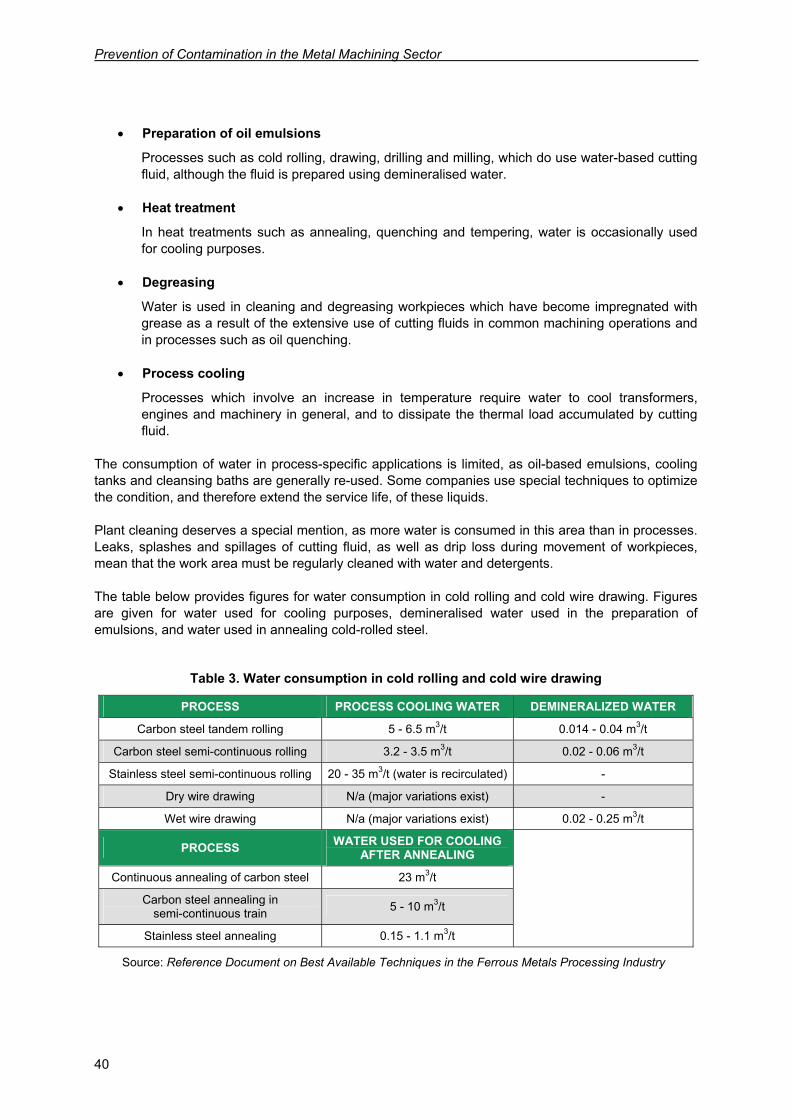
The consumption of water in process-specific applications is limited, as oil-based emulsions, cooling tanks and cleansing baths are generally re-used. Some companies use special techniques to optimize the condition, and therefore extend the service life, of these liquids. Plant cleaning deserves a special mention, as more water is consumed in this area than in processes. Leaks, splashes and spillages of cutting fluid, as well as drip loss during movement of workpieces, mean that the work area must be regularly cleaned with water and detergents. The table below provides figures for water consumption in cold rolling and cold wire drawing. Figures are given for water used for cooling purposes, demineralised water used in the preparation of emulsions, and water used in annealing cold-rolled steel.
Table 3. Water consumption in cold rolling and cold wire drawing
PROCESS PROCESS COOLING WATER DEMINERALIZED WATER
Carbon steel tandem rolling 5 - 6.5 m3/t 0.014 - 0.04 m3/t
Carbon steel semi-continuous rolling 3.2 - 3.5 m3/t 0.02 - 0.06 m3/t
Stainless steel semi-continuous rolling 20 - 35 m3/t (water is recirculated) -
Dry wire drawing N/a (major variations exist) -
Wet wire drawing N/a (major variations exist) 0.02 - 0.25 m3/t
PROCESS WATER USED FOR COOLING AFTER ANNEALING
Continuous annealing of carbon steel 23 m3/t
Carbon steel annealing in semi-continuous train 5 - 10 m3/t
Stainless steel annealing 0.15 - 1.1 m3/t
Source: Reference Document on Best Available Techniques in the Ferrous Metals Processing Industry
Environmental hazards in the metal machining sector
41
As the table shows, consumption of demineralized water is low in comparison with the amount of water used in cooling, since not much water is required for the dilution of oils. Note, also, the absence of water consumption in operations where oil emulsions are not used, such as dry wire drawing, where the lubricant is based on soap plus a variety of additives, and cold rolling of stainless steel, where oil, not emulsions, is typically used. Consumption of water in annealing varies according to the method used for cooling the metal.
3.2. Energy consumption
Companies in the metal machining sector use two sources of energy: electricity (the principal source) and diesel or natural gas (the secondary source). These sources of energy are used in two different stages in machining:
• Consumption of electrical energy for powering the machinery used in the various forming and machining processes (rolling trains, wire drawing machines, presses, turning machines, milling cutters etc.), auxiliary equipment such as degreasers, centrifuges used in recycling oil from workpieces and discard etc., as well as pumps, transmissions, fans etc.
• Gas / diesel consumption by furnaces and boilers used in heat treatments.
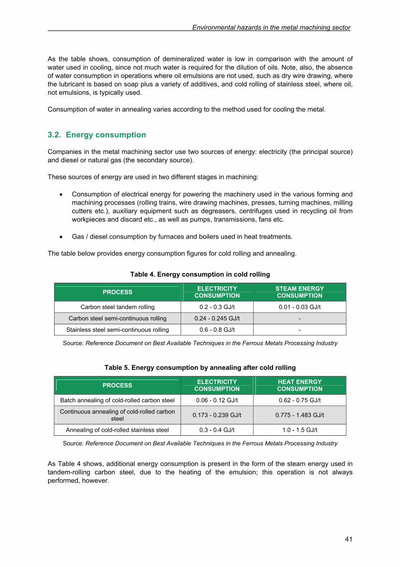
The table below provides energy consumption figures for cold rolling and annealing.
Table 4. Energy consumption in cold rolling
PROCESS ELECTRICITY CONSUMPTION
STEAM ENERGY CONSUMPTION
Carbon steel tandem rolling 0.2 - 0.3 GJ/t 0.01 - 0.03 GJ/t
Carbon steel semi-continuous rolling 0.24 - 0.245 GJ/t -
Stainless steel semi-continuous rolling 0.6 - 0.8 GJ/t -
Source: Reference Document on Best Available Techniques in the Ferrous Metals Processing Industry
Table 5. Energy consumption by annealing after cold rolling
PROCESS ELECTRICITY CONSUMPTION
HEAT ENERGY CONSUMPTION
Batch annealing of cold-rolled carbon steel 0.06 - 0.12 GJ/t 0.62 - 0.75 GJ/t
Continuous annealing of cold-rolled carbon steel 0.173 - 0.239 GJ/t 0.775 - 1.483 GJ/t
Annealing of cold-rolled stainless steel 0.3 - 0.4 GJ/t 1.0 - 1.5 GJ/t
Source: Reference Document on Best Available Techniques in the Ferrous Metals Processing Industry
As Table 4 shows, additional energy consumption is present in the form of the steam energy used in tandem-rolling carbon steel, due to the heating of the emulsion; this operation is not always performed, however.
Prevention of Contamination in the Metal Machining Sector
42
3.3. Liquid waste
The liquid effluents produced in the metal machining sector vary in composition depending upon the process which generates them. Typically, effluents will have a high content of oils, grease, suspended solids and dissolved or semi-dissolved organic matter, deriving from the use of cutting fluids. In general, liquid waste can be divided into the following categories:
• Liquid waste produced by forming and machining processes: Spent cutting fluids
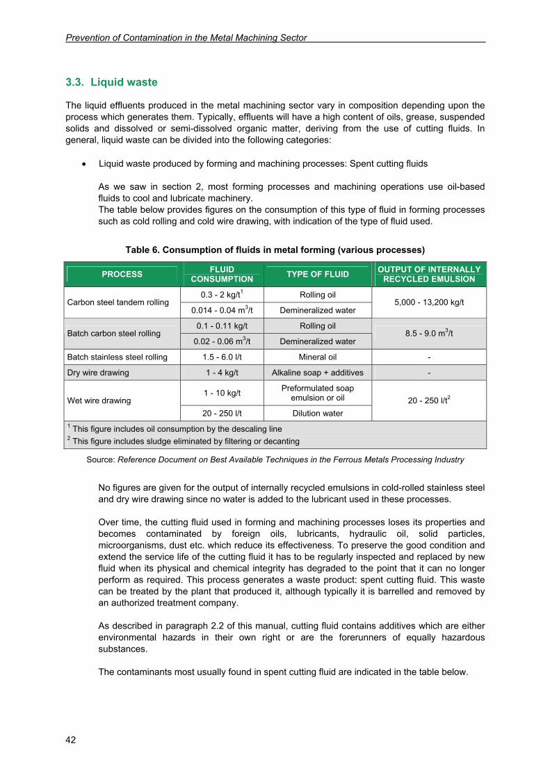
As we saw in section 2, most forming processes and machining operations use oil-based fluids to cool and lubricate machinery. The table below provides figures on the consumption of this type of fluid in forming processes such as cold rolling and cold wire drawing, with indication of the type of fluid used.
Table 6. Consumption of fluids in metal forming (various processes)
PROCESS FLUID CONSUMPTION TYPE OF FLUID OUTPUT OF INTERNALLY
RECYCLED EMULSION
0.3 - 2 kg/t1 Rolling oil Carbon steel tandem rolling
0.014 - 0.04 m3/t Demineralized water 5,000 - 13,200 kg/t
0.1 - 0.11 kg/t Rolling oil Batch carbon steel rolling
0.02 - 0.06 m3/t Demineralized water 8.5 - 9.0 m3/t
Batch stainless steel rolling 1.5 - 6.0 l/t Mineral oil -
Dry wire drawing 1 - 4 kg/t Alkaline soap + additives -
1 - 10 kg/t Preformulated soap emulsion or oil Wet wire drawing
20 - 250 l/t Dilution water 20 - 250 l/t2
1 This figure includes oil consumption by the descaling line 2 This figure includes sludge eliminated by filtering or decanting
Source: Reference Document on Best Available Techniques in the Ferrous Metals Processing Industry
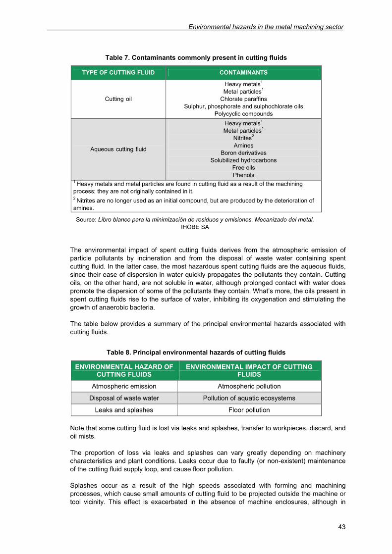
No figures are given for the output of internally recycled emulsions in cold-rolled stainless steel and dry wire drawing since no water is added to the lubricant used in these processes. Over time, the cutting fluid used in forming and machining processes loses its properties and becomes contaminated by foreign oils, lubricants, hydraulic oil, solid particles, microorganisms, dust etc. which reduce its effectiveness. To preserve the good condition and extend the service life of the cutting fluid it has to be regularly inspected and replaced by new fluid when its physical and chemical integrity has degraded to the point that it can no longer perform as required. This process generates a waste product: spent cutting fluid. This waste can be treated by the plant that produced it, although typically it is barrelled and removed by an authorized treatment company. As described in paragraph 2.2 of this manual, cutting fluid contains additives which are either environmental hazards in their own right or are the forerunners of equally hazardous substances. The contaminants most usually found in spent cutting fluid are indicated in the table below.
Environmental hazards in the metal machining sector
43
Table 7. Contaminants commonly present in cutting fluids
TYPE OF CUTTING FLUID CONTAMINANTS
Cutting oil
Heavy metals1 Metal particles1
Chlorate paraffins Sulphur, phosphorate and sulphochlorate oils
Polycyclic compounds
Aqueous cutting fluid
Heavy metals1 Metal particles1
Nitrites2 Amines
Boron derivatives Solubilized hydrocarbons
Free oils Phenols
1 Heavy metals and metal particles are found in cutting fluid as a result of the machining process; they are not originally contained in it. 2 Nitrites are no longer used as an initial compound, but are produced by the deterioration of amines.
Source: Libro blanco para la minimización de residuos y emisiones. Mecanizado del metal, IHOBE SA
The environmental impact of spent cutting fluids derives from the atmospheric emission of particle pollutants by incineration and from the disposal of waste water containing spent cutting fluid. In the latter case, the most hazardous spent cutting fluids are the aqueous fluids, since their ease of dispersion in water quickly propagates the pollutants they contain. Cutting oils, on the other hand, are not soluble in water, although prolonged contact with water does promote the dispersion of some of the pollutants they contain. What’s more, the oils present in spent cutting fluids rise to the surface of water, inhibiting its oxygenation and stimulating the growth of anaerobic bacteria. The table below provides a summary of the principal environmental hazards associated with cutting fluids.
Table 8. Principal environmental hazards of cutting fluids
ENVIRONMENTAL HAZARD OF CUTTING FLUIDS
ENVIRONMENTAL IMPACT OF CUTTING FLUIDS
Atmospheric emission Atmospheric pollution
Disposal of waste water Pollution of aquatic ecosystems
Leaks and splashes Floor pollution
Note that some cutting fluid is lost via leaks and splashes, transfer to workpieces, discard, and oil mists. The proportion of loss via leaks and splashes can vary greatly depending on machinery characteristics and plant conditions. Leaks occur due to faulty (or non-existent) maintenance of the cutting fluid supply loop, and cause floor pollution. Splashes occur as a result of the high speeds associated with forming and machining processes, which cause small amounts of cutting fluid to be projected outside the machine or tool vicinity. This effect is exacerbated in the absence of machine enclosures, although in
Prevention of Contamination in the Metal Machining Sector
44
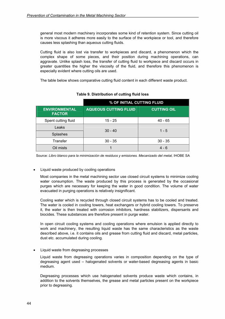
general most modern machinery incorporates some kind of retention system. Since cutting oil is more viscous it adheres more easily to the surface of the workpiece or tool, and therefore causes less splashing than aqueous cutting fluids. Cutting fluid is also lost via transfer to workpieces and discard, a phenomenon which the complex shape of some pieces, and their position during machining operations, can aggravate. Unlike splash loss, the transfer of cutting fluid to workpiece and discard occurs in greater quantities the higher the viscosity of the fluid, and therefore this phenomenon is especially evident where cutting oils are used. The table below shows comparative cutting fluid content in each different waste product.
Table 9. Distribution of cutting fluid loss
% OF INITIAL CUTTING FLUID
ENVIRONMENTAL FACTOR
AQUEOUS CUTTING FLUID CUTTING OIL
Spent cutting fluid 15 - 25 40 - 65
Leaks
Splashes 30 - 40 1 - 5
Transfer 30 - 35 30 - 35
Oil mists 1 4 - 6
Source: Libro blanco para la minimización de residuos y emisiones. Mecanizado del metal, IHOBE SA
• Liquid waste produced by cooling operations
Most companies in the metal machining sector use closed circuit systems to minimize cooling water consumption. The waste produced by this process is generated by the occasional purges which are necessary for keeping the water in good condition. The volume of water evacuated in purging operations is relatively insignificant. Cooling water which is recycled through closed circuit systems has to be cooled and treated. The water is cooled in cooling towers, heat exchangers or hybrid cooling towers. To preserve it, the water is then treated with corrosion inhibitors, hardness stabilizers, dispersants and biocides. These substances are therefore present in purge water. In open circuit cooling systems and cooling operations where emulsion is applied directly to work and machinery, the resulting liquid waste has the same characteristics as the waste described above, i.e. it contains oils and grease from cutting fluid and discard, metal particles, dust etc. accumulated during cooling.
• Liquid waste from degreasing processes
Liquid waste from degreasing operations varies in composition depending on the type of degreasing agent used – halogenated solvents or water-based degreasing agents in basic medium. Degreasing processes which use halogenated solvents produce waste which contains, in addition to the solvents themselves, the grease and metal particles present on the workpiece prior to degreasing.
Environmental hazards in the metal machining sector
45
With water-based degreasing agents in basic medium, the resulting waste contains oils, grease, sodium and hydroxide salts, carbonates, phosphates and metasilicates, as well as surfactants and organic chelating agents (EDTA, NTA etc.). The volume of waste produced by degreasing operations can be reduced by regeneration of degreasing solutions. These solutions are typically recycled using a closed circuit system, although they gradually lose their effectiveness and have to be purged occasionally. Since it contains detergents and solvents, the waste produced by degreasing operations has to be treated.
• Waste water produced by plant cleaning operations
The waste water produced as a result of plant cleaning operations contains oil from cutting fluid splash loss and leaks as well as the detergents used in cleaning.
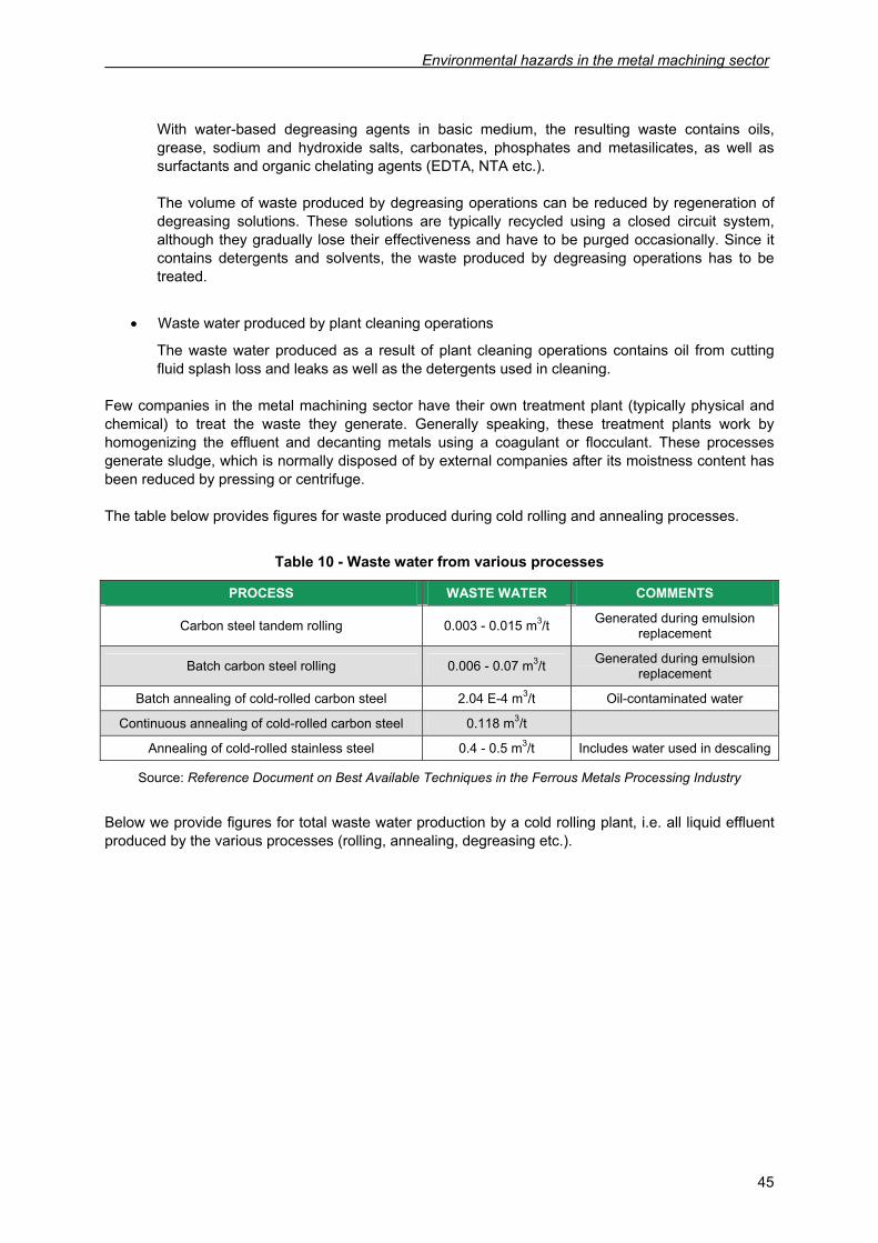
Few companies in the metal machining sector have their own treatment plant (typically physical and chemical) to treat the waste they generate. Generally speaking, these treatment plants work by homogenizing the effluent and decanting metals using a coagulant or flocculant. These processes generate sludge, which is normally disposed of by external companies after its moistness content has been reduced by pressing or centrifuge. The table below provides figures for waste produced during cold rolling and annealing processes.
Table 10 - Waste water from various processes
PROCESS WASTE WATER COMMENTS
Carbon steel tandem rolling 0.003 - 0.015 m3/t Generated during emulsion replacement
Batch carbon steel rolling 0.006 - 0.07 m3/t Generated during emulsion replacement
Batch annealing of cold-rolled carbon steel 2.04 E-4 m3/t Oil-contaminated water
Continuous annealing of cold-rolled carbon steel 0.118 m3/t
Annealing of cold-rolled stainless steel 0.4 - 0.5 m3/t Includes water used in descaling
Source: Reference Document on Best Available Techniques in the Ferrous Metals Processing Industry
Below we provide figures for total waste water production by a cold rolling plant, i.e. all liquid effluent produced by the various processes (rolling, annealing, degreasing etc.).
Prevention of Contamination in the Metal Machining Sector
46
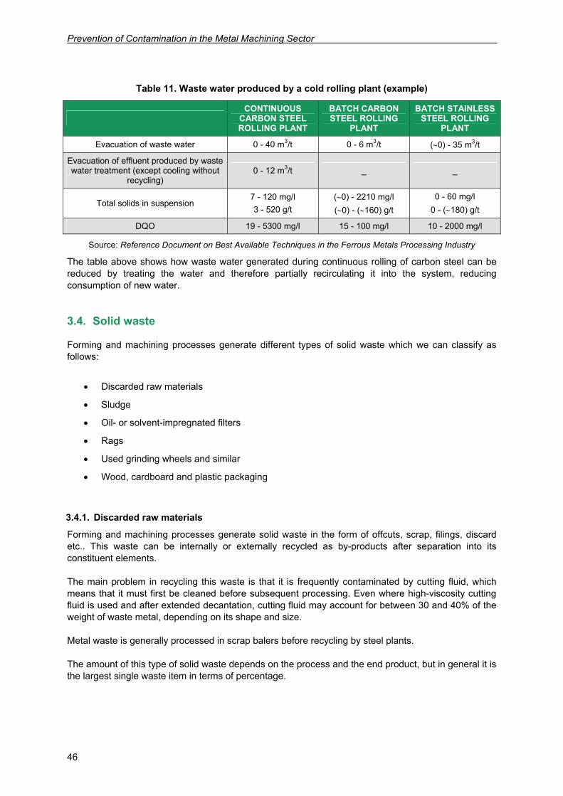
Table 11. Waste water produced by a cold rolling plant (example)
CONTINUOUS
CARBON STEEL ROLLING PLANT
BATCH CARBON STEEL ROLLING
PLANT
BATCH STAINLESS STEEL ROLLING
PLANT
Evacuation of waste water 0 - 40 m3/t 0 - 6 m3/t (∼0) - 35 m3/t
Evacuation of effluent produced by waste water treatment (except cooling without
recycling) 0 - 12 m3/t _ _
Total solids in suspension 7 - 120 mg/l 3 - 520 g/t
(∼0) - 2210 mg/l (∼0) - (∼160) g/t
0 - 60 mg/l 0 - (∼180) g/t
DQO 19 - 5300 mg/l 15 - 100 mg/l 10 - 2000 mg/l
Source: Reference Document on Best Available Techniques in the Ferrous Metals Processing Industry
The table above shows how waste water generated during continuous rolling of carbon steel can be reduced by treating the water and therefore partially recirculating it into the system, reducing consumption of new water.
3.4. Solid waste
Forming and machining processes generate different types of solid waste which we can classify as follows:
• Discarded raw materials
• Sludge
• Oil- or solvent-impregnated filters
• Rags
• Used grinding wheels and similar
• Wood, cardboard and plastic packaging
3.4.1. Discarded raw materials
Forming and machining processes generate solid waste in the form of offcuts, scrap, filings, discard etc.. This waste can be internally or externally recycled as by-products after separation into its constituent elements. The main problem in recycling this waste is that it is frequently contaminated by cutting fluid, which means that it must first be cleaned before subsequent processing. Even where high-viscosity cutting fluid is used and after extended decantation, cutting fluid may account for between 30 and 40% of the weight of waste metal, depending on its shape and size. Metal waste is generally processed in scrap balers before recycling by steel plants. The amount of this type of solid waste depends on the process and the end product, but in general it is the largest single waste item in terms of percentage.
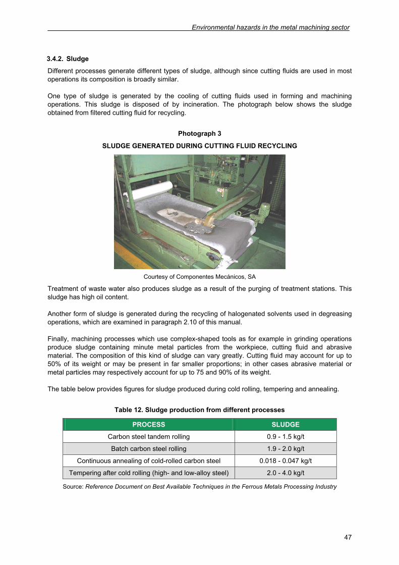
Environmental hazards in the metal machining sector
47
3.4.2. Sludge
Different processes generate different types of sludge, although since cutting fluids are used in most operations its composition is broadly similar. One type of sludge is generated by the cooling of cutting fluids used in forming and machining operations. This sludge is disposed of by incineration. The photograph below shows the sludge obtained from filtered cutting fluid for recycling.
Photograph 3
SLUDGE GENERATED DURING CUTTING FLUID RECYCLING
Courtesy of Componentes Mecánicos, SA
Treatment of waste water also produces sludge as a result of the purging of treatment stations. This sludge has high oil content. Another form of sludge is generated during the recycling of halogenated solvents used in degreasing operations, which are examined in paragraph 2.10 of this manual. Finally, machining processes which use complex-shaped tools as for example in grinding operations produce sludge containing minute metal particles from the workpiece, cutting fluid and abrasive material. The composition of this kind of sludge can vary greatly. Cutting fluid may account for up to 50% of its weight or may be present in far smaller proportions; in other cases abrasive material or metal particles may respectively account for up to 75 and 90% of its weight. The table below provides figures for sludge produced during cold rolling, tempering and annealing.
Table 12. Sludge production from different processes
PROCESS SLUDGE
Carbon steel tandem rolling 0.9 - 1.5 kg/t
Batch carbon steel rolling 1.9 - 2.0 kg/t
Continuous annealing of cold-rolled carbon steel 0.018 - 0.047 kg/t
Tempering after cold rolling (high- and low-alloy steel) 2.0 - 4.0 kg/t
Source: Reference Document on Best Available Techniques in the Ferrous Metals Processing Industry
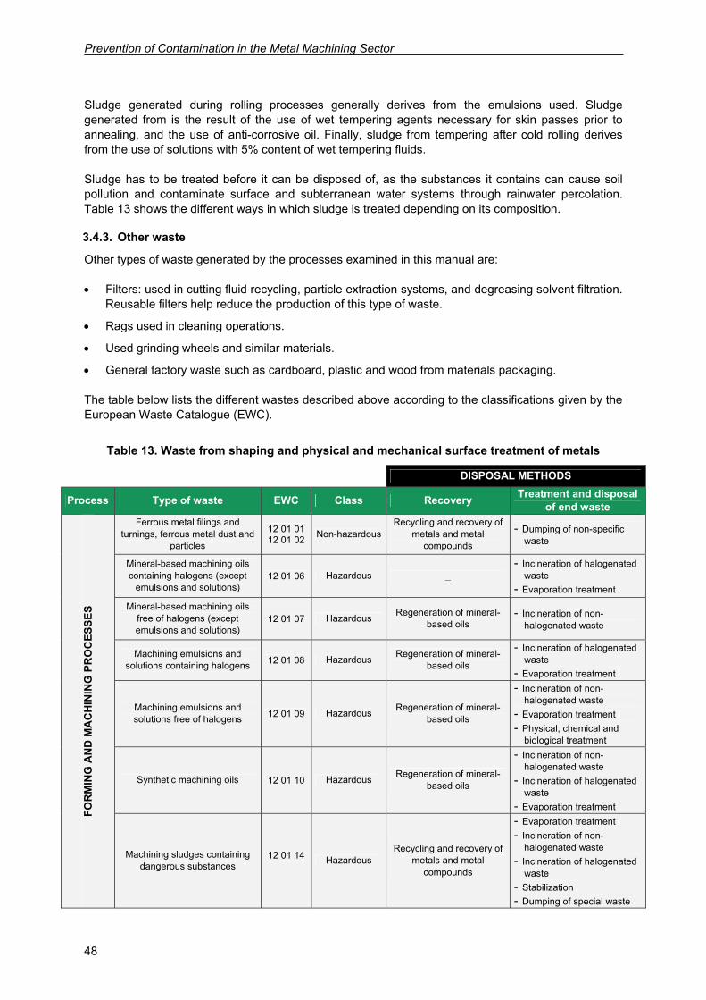
Prevention of Contamination in the Metal Machining Sector
48
Sludge generated during rolling processes generally derives from the emulsions used. Sludge generated from is the result of the use of wet tempering agents necessary for skin passes prior to annealing, and the use of anti-corrosive oil. Finally, sludge from tempering after cold rolling derives from the use of solutions with 5% content of wet tempering fluids. Sludge has to be treated before it can be disposed of, as the substances it contains can cause soil pollution and contaminate surface and subterranean water systems through rainwater percolation. Table 13 shows the different ways in which sludge is treated depending on its composition.
3.4.3. Other waste
Other types of waste generated by the processes examined in this manual are: • Filters: used in cutting fluid recycling, particle extraction systems, and degreasing solvent filtration.
Reusable filters help reduce the production of this type of waste.
• Rags used in cleaning operations.
• Used grinding wheels and similar materials.
• General factory waste such as cardboard, plastic and wood from materials packaging. The table below lists the different wastes described above according to the classifications given by the European Waste Catalogue (EWC).
Table 13. Waste from shaping and physical and mechanical surface treatment of metals
DISPOSAL METHODS
Process Type of waste EWC Class Recovery Treatment and disposal of end waste
Ferrous metal filings and turnings, ferrous metal dust and
particles
12 01 01 12 01 02 Non-hazardous
Recycling and recovery of metals and metal
compounds
- Dumping of non-specific waste
Mineral-based machining oils containing halogens (except
emulsions and solutions) 12 01 06 Hazardous _
- Incineration of halogenated waste
- Evaporation treatment
Mineral-based machining oils free of halogens (except emulsions and solutions)
12 01 07 Hazardous Regeneration of mineral-based oils
- Incineration of non-halogenated waste
Machining emulsions and solutions containing halogens 12 01 08 Hazardous Regeneration of mineral-
based oils
- Incineration of halogenated waste
- Evaporation treatment
Machining emulsions and solutions free of halogens 12 01 09 Hazardous Regeneration of mineral-
based oils
- Incineration of non-halogenated waste
- Evaporation treatment - Physical, chemical and
biological treatment
Synthetic machining oils 12 01 10 Hazardous Regeneration of mineral-based oils
- Incineration of non-halogenated waste
- Incineration of halogenated waste
- Evaporation treatment FOR
MIN
G A
ND
MA
CH
ININ
G P
RO
CES
SES
Machining sludges containing dangerous substances
12 01 14 Hazardous
Recycling and recovery of metals and metal
compounds
- Evaporation treatment - Incineration of non-
halogenated waste - Incineration of halogenated
waste - Stabilization - Dumping of special waste
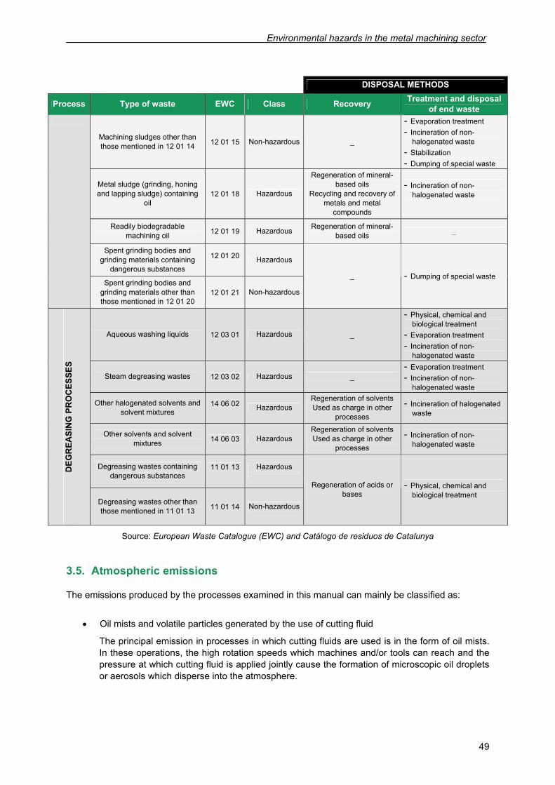
Environmental hazards in the metal machining sector
49
DISPOSAL METHODS
Process Type of waste EWC Class Recovery Treatment and disposal of end waste
Machining sludges other than those mentioned in 12 01 14 12 01 15 Non-hazardous _
- Evaporation treatment - Incineration of non-
halogenated waste - Stabilization - Dumping of special waste
Metal sludge (grinding, honing and lapping sludge) containing
oil 12 01 18 Hazardous
Regeneration of mineral-based oils
Recycling and recovery of metals and metal
compounds
- Incineration of non-halogenated waste
Readily biodegradable machining oil 12 01 19 Hazardous Regeneration of mineral-
based oils _
Spent grinding bodies and grinding materials containing
dangerous substances
12 01 20 Hazardous
Spent grinding bodies and grinding materials other than those mentioned in 12 01 20
12 01 21 Non-hazardous
_ - Dumping of special waste
Aqueous washing liquids 12 03 01 Hazardous _
- Physical, chemical and biological treatment
- Evaporation treatment - Incineration of non-
halogenated waste
Steam degreasing wastes 12 03 02 Hazardous _ - Evaporation treatment - Incineration of non-
halogenated waste
Other halogenated solvents and solvent mixtures
14 06 02 Hazardous
Regeneration of solvents Used as charge in other
processes
- Incineration of halogenated waste
Other solvents and solvent mixtures 14 06 03 Hazardous
Regeneration of solvents Used as charge in other
processes
- Incineration of non-halogenated waste
Degreasing wastes containing dangerous substances
11 01 13
Hazardous
DEG
REA
SIN
G P
RO
CES
SES
Degreasing wastes other than those mentioned in 11 01 13 11 01 14 Non-hazardous
Regeneration of acids or bases
- Physical, chemical and biological treatment
Source: European Waste Catalogue (EWC) and Catálogo de residuos de Catalunya
3.5. Atmospheric emissions
The emissions produced by the processes examined in this manual can mainly be classified as:
• Oil mists and volatile particles generated by the use of cutting fluid
The principal emission in processes in which cutting fluids are used is in the form of oil mists. In these operations, the high rotation speeds which machines and/or tools can reach and the pressure at which cutting fluid is applied jointly cause the formation of microscopic oil droplets or aerosols which disperse into the atmosphere.
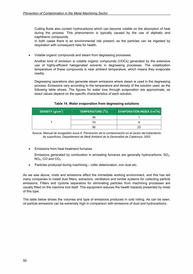
Prevention of Contamination in the Metal Machining Sector
50
Cutting fluids also contain hydrocarbons which can become volatile on the absorption of heat during the process. This phenomenon is typically caused by the use of aliphatic and naphthenic compounds. In both cases there is an environmental risk present, as the particles can be ingested by respiration with consequent risks for health.
• Volatile organic compounds and steam from degreasing processes
Another kind of emission is volatile organic compounds (VOCs) generated by the extensive use of highly-efficient halogenated solvents in degreasing processes. The volatilization temperature of these compounds is near ambient temperature, which means they evaporate readily. Degreasing operations also generate steam emissions where steam is used in the degreasing process. Emissions vary according to the temperature and density of the solution used, as the following table shows. The figures for water loss through evaporation are approximate, as exact values depend on the specific characteristics of each solution.
Table 14. Water evaporation from degreasing solutions
DENSITY (g/cm3) TEMPERATURE (0C) EVAPORATION INDEX (l·m2/h)
50 1
70 9 1
90 23
Source: Manual de ecogestión issue 6. Prevención de la contaminación en el sector del tratamiento de superficies, Departament de Medi Ambient de la Generalitat de Catalunya, 2002
• Emissions from heat treatment furnaces
Emissions generated by combustion in annealing furnaces are generally hydrocarbons, SO2, NOX, CO and CO2.
• Particles produced during machining – roller deterioration, iron dust etc.
As we saw above, mists and emissions affect the immediate working environment, and this has led many companies to install dust filters, extractors, ventilators and similar systems for collecting particle emissions. Filters and cyclone separators for eliminating particles from machining processes are usually fitted on the machine tool itself. This equipment reduces the health hazards presented by mists of this type. The table below shows the volumes and type of emissions produced in cold rolling. As can be seen, oil particle emissions can be extremely high in comparison with emissions of dust and hydrocarbons.
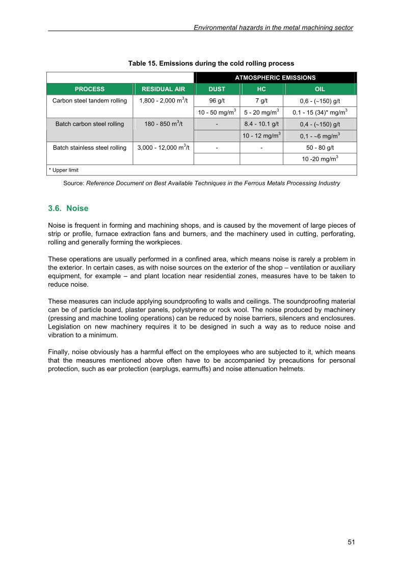
Environmental hazards in the metal machining sector
51
Table 15. Emissions during the cold rolling process
ATMOSPHERIC EMISSIONS
PROCESS RESIDUAL AIR DUST HC OIL
96 g/t 7 g/t 0,6 - (∼150) g/t Carbon steel tandem rolling 1,800 - 2,000 m3/t
10 - 50 mg/m3 5 - 20 mg/m3 0.1 - 15 (34)* mg/m3
- 8.4 - 10.1 g/t 0,4 - (∼150) g/t Batch carbon steel rolling 180 - 850 m3/t
10 - 12 mg/m3 0,1 - ∼6 mg/m3
- - 50 - 80 g/t Batch stainless steel rolling 3,000 - 12,000 m3/t
10 -20 mg/m3
* Upper limit
Source: Reference Document on Best Available Techniques in the Ferrous Metals Processing Industry
3.6. Noise
Noise is frequent in forming and machining shops, and is caused by the movement of large pieces of strip or profile, furnace extraction fans and burners, and the machinery used in cutting, perforating, rolling and generally forming the workpieces. These operations are usually performed in a confined area, which means noise is rarely a problem in the exterior. In certain cases, as with noise sources on the exterior of the shop – ventilation or auxiliary equipment, for example – and plant location near residential zones, measures have to be taken to reduce noise. These measures can include applying soundproofing to walls and ceilings. The soundproofing material can be of particle board, plaster panels, polystyrene or rock wool. The noise produced by machinery (pressing and machine tooling operations) can be reduced by noise barriers, silencers and enclosures. Legislation on new machinery requires it to be designed in such a way as to reduce noise and vibration to a minimum. Finally, noise obviously has a harmful effect on the employees who are subjected to it, which means that the measures mentioned above often have to be accompanied by precautions for personal protection, such as ear protection (earplugs, earmuffs) and noise attenuation helmets.

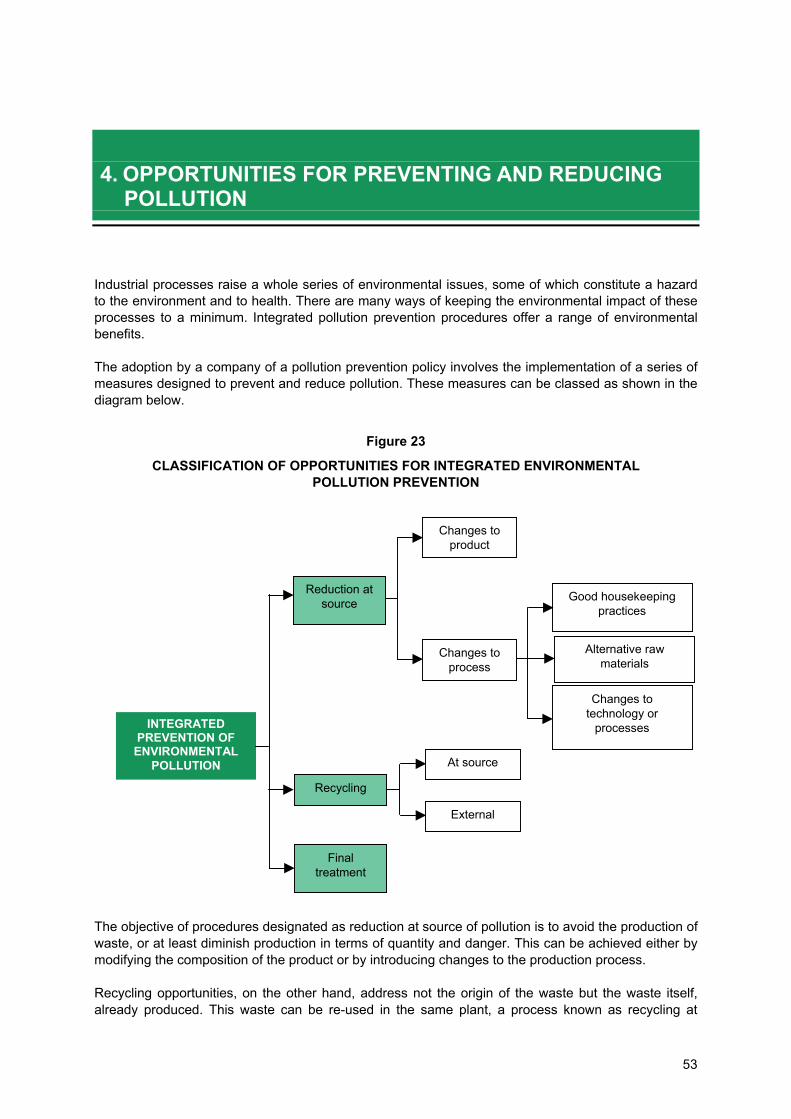
53
4. OPPORTUNITIES FOR PREVENTING AND REDUCING
POLLUTION
Industrial processes raise a whole series of environmental issues, some of which constitute a hazard to the environment and to health. There are many ways of keeping the environmental impact of these processes to a minimum. Integrated pollution prevention procedures offer a range of environmental benefits. The adoption by a company of a pollution prevention policy involves the implementation of a series of measures designed to prevent and reduce pollution. These measures can be classed as shown in the diagram below.
Figure 23
CLASSIFICATION OF OPPORTUNITIES FOR INTEGRATED ENVIRONMENTAL POLLUTION PREVENTION
The objective of procedures designated as reduction at source of pollution is to avoid the production of waste, or at least diminish production in terms of quantity and danger. This can be achieved either by modifying the composition of the product or by introducing changes to the production process. Recycling opportunities, on the other hand, address not the origin of the waste but the waste itself, already produced. This waste can be re-used in the same plant, a process known as recycling at
INTEGRATED PREVENTION OF ENVIRONMENTAL
POLLUTION
Reduction at source
Recycling
Changes to product
Changes to process
Good housekeeping practices
Alternative raw materials
Changes to technology or
processes
At source
External
Final treatment
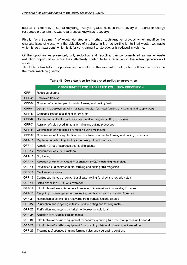
Prevention of Contamination in the Metal Machining Sector
54
source, or externally (external recycling). Recycling also includes the recovery of material or energy resources present in the waste (a process known as recovery). Finally, “end treatment” of waste denotes any method, technique or process which modifies the characteristics of waste with the objective of neutralizing it or converting it into inert waste, i.e. waste which is less hazardous, which is fit for consignment to storage, or is reduced in volume. Of the opportunities presented, only reduction and recycling can be considered as viable waste reduction opportunities, since they effectively contribute to a reduction in the actual generation of waste. The table below lists the opportunities presented in this manual for integrated pollution prevention in the metal machining sector.
Table 16. Opportunities for integrated pollution prevention
OPPORTUNITIES FOR INTEGRATED POLLUTION PREVENTION
OPP-1 Redesign of parts
OPP-2 Employee training
OPP-3 Creation of a control plan for metal forming and cutting fluids
OPP-4 Design and deployment of a maintenance plan for metal forming and cutting fluid supply loops
OPP-5 Compatibilization of cutting fluid products
OPP-6 Disinfection of fluid loops to improve metal forming and cutting processes
OPP-7 Aeration of fluids used in metal forming and cutting processes
OPP-8 Optimization of workpiece orientation during machining
OPP-9 Optimization of fluid application methods to improve metal forming and cutting processes
OPP-10 Replacement of cutting fluid by other less pollutant products
OPP-11 Adoption of less hazardous degreasing agents
OPP-12 Minimization of surplus material
OPP-13 Dry tooling
OPP-14 Adoption of Minimum Quantity Lubrication (MQL) machining technology
OPP-15 Installation of a common metal forming and cutting fluid magazine
OPP-16 Machine enclosures
OPP-17 Continuous instead of conventional batch rolling for alloy and low-alloy steel
OPP-18 Batch annealing 100% with hydrogen
OPP-19 Introduction of low NOX burners to reduce NOX emissions in annealing furnaces
OPP-20 Recycling of waste gases for preheating combustion air in annealing furnaces
OPP-21 Reinjection of cutting fluid recovered from workpieces and discard
OPP-22 Purification and recycling of fluids used in cutting and forming metals
OPP-23 Purification and recycling of alkaline degreasing solutions
OPP-24 Adoption of re-usable filtration media
OPP-25 Introduction of auxiliary equipment for separating cutting fluid from workpieces and discard
OPP-26 Introduction of auxiliary equipment for extracting mists and other ambient emissions
OPP-27 Treatment of spent cutting and forming fluids and degreasing solutions
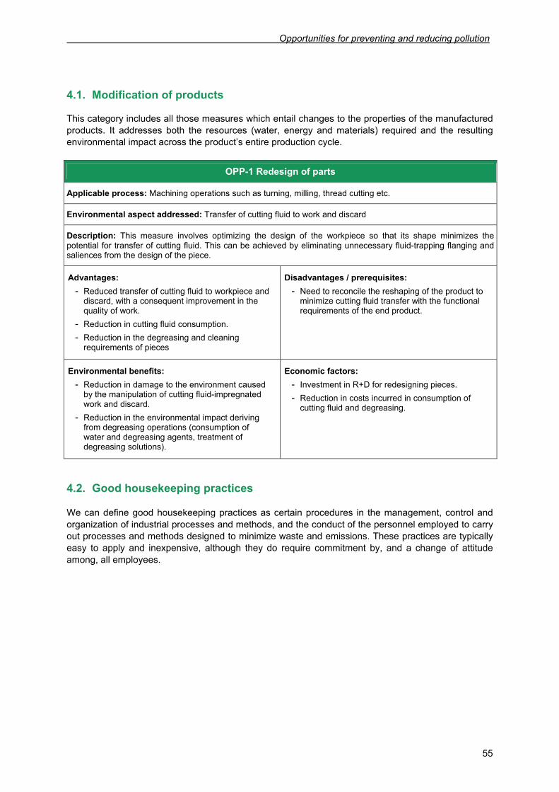
Opportunities for preventing and reducing pollution
55
4.1. Modification of products
This category includes all those measures which entail changes to the properties of the manufactured products. It addresses both the resources (water, energy and materials) required and the resulting environmental impact across the product’s entire production cycle.
OPP-1 Redesign of parts
Applicable process: Machining operations such as turning, milling, thread cutting etc.
Environmental aspect addressed: Transfer of cutting fluid to work and discard
Description: This measure involves optimizing the design of the workpiece so that its shape minimizes the potential for transfer of cutting fluid. This can be achieved by eliminating unnecessary fluid-trapping flanging and saliences from the design of the piece.
Advantages: - Reduced transfer of cutting fluid to workpiece and
discard, with a consequent improvement in the quality of work.
- Reduction in cutting fluid consumption. - Reduction in the degreasing and cleaning
requirements of pieces
Disadvantages / prerequisites: - Need to reconcile the reshaping of the product to
minimize cutting fluid transfer with the functional requirements of the end product.
Environmental benefits: - Reduction in damage to the environment caused
by the manipulation of cutting fluid-impregnated work and discard.
- Reduction in the environmental impact deriving from degreasing operations (consumption of water and degreasing agents, treatment of degreasing solutions).
Economic factors: - Investment in R+D for redesigning pieces. - Reduction in costs incurred in consumption of
cutting fluid and degreasing.
4.2. Good housekeeping practices
We can define good housekeeping practices as certain procedures in the management, control and organization of industrial processes and methods, and the conduct of the personnel employed to carry out processes and methods designed to minimize waste and emissions. These practices are typically easy to apply and inexpensive, although they do require commitment by, and a change of attitude among, all employees.
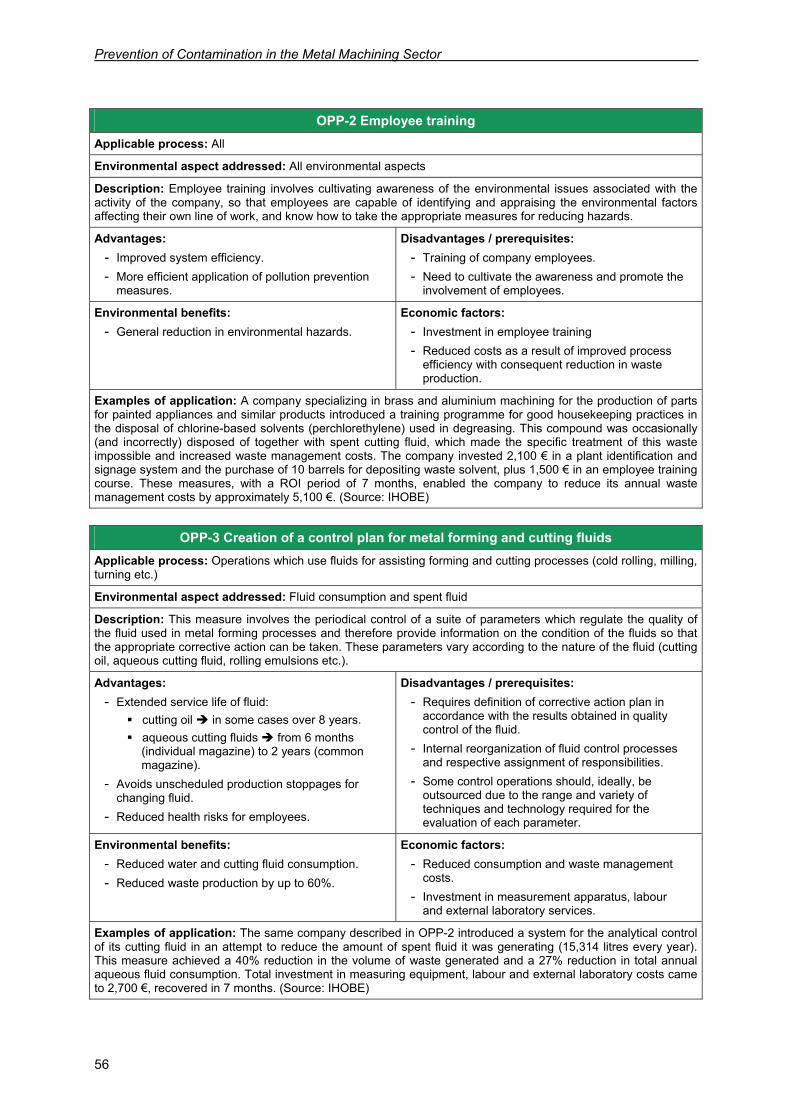
Prevention of Contamination in the Metal Machining Sector
56
OPP-3 Creation of a control plan for metal forming and cutting fluids
Applicable process: Operations which use fluids for assisting forming and cutting processes (cold rolling, milling, turning etc.)
Environmental aspect addressed: Fluid consumption and spent fluid
Description: This measure involves the periodical control of a suite of parameters which regulate the quality of the fluid used in metal forming processes and therefore provide information on the condition of the fluids so that the appropriate corrective action can be taken. These parameters vary according to the nature of the fluid (cutting oil, aqueous cutting fluid, rolling emulsions etc.).
Advantages: - Extended service life of fluid:
cutting oil in some cases over 8 years. aqueous cutting fluids from 6 months
(individual magazine) to 2 years (common magazine).
- Avoids unscheduled production stoppages for changing fluid.
- Reduced health risks for employees.
Disadvantages / prerequisites: - Requires definition of corrective action plan in
accordance with the results obtained in quality control of the fluid.
- Internal reorganization of fluid control processes and respective assignment of responsibilities.
- Some control operations should, ideally, be outsourced due to the range and variety of techniques and technology required for the evaluation of each parameter.
Environmental benefits: - Reduced water and cutting fluid consumption. - Reduced waste production by up to 60%.
Economic factors: - Reduced consumption and waste management
costs. - Investment in measurement apparatus, labour
and external laboratory services.
Examples of application: The same company described in OPP-2 introduced a system for the analytical control of its cutting fluid in an attempt to reduce the amount of spent fluid it was generating (15,314 litres every year). This measure achieved a 40% reduction in the volume of waste generated and a 27% reduction in total annual aqueous fluid consumption. Total investment in measuring equipment, labour and external laboratory costs came to 2,700 €, recovered in 7 months. (Source: IHOBE)
OPP-2 Employee training Applicable process: All
Environmental aspect addressed: All environmental aspects
Description: Employee training involves cultivating awareness of the environmental issues associated with the activity of the company, so that employees are capable of identifying and appraising the environmental factors affecting their own line of work, and know how to take the appropriate measures for reducing hazards.
Advantages: - Improved system efficiency. - More efficient application of pollution prevention
measures.
Disadvantages / prerequisites: - Training of company employees. - Need to cultivate the awareness and promote the
involvement of employees. Environmental benefits:
- General reduction in environmental hazards. Economic factors:
- Investment in employee training - Reduced costs as a result of improved process
efficiency with consequent reduction in waste production.
Examples of application: A company specializing in brass and aluminium machining for the production of parts for painted appliances and similar products introduced a training programme for good housekeeping practices in the disposal of chlorine-based solvents (perchlorethylene) used in degreasing. This compound was occasionally (and incorrectly) disposed of together with spent cutting fluid, which made the specific treatment of this waste impossible and increased waste management costs. The company invested 2,100 € in a plant identification and signage system and the purchase of 10 barrels for depositing waste solvent, plus 1,500 € in an employee training course. These measures, with a ROI period of 7 months, enabled the company to reduce its annual waste management costs by approximately 5,100 €. (Source: IHOBE)
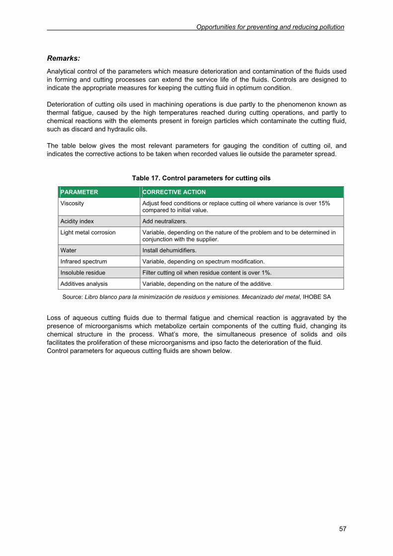
Opportunities for preventing and reducing pollution
57
Remarks:
Analytical control of the parameters which measure deterioration and contamination of the fluids used in forming and cutting processes can extend the service life of the fluids. Controls are designed to indicate the appropriate measures for keeping the cutting fluid in optimum condition. Deterioration of cutting oils used in machining operations is due partly to the phenomenon known as thermal fatigue, caused by the high temperatures reached during cutting operations, and partly to chemical reactions with the elements present in foreign particles which contaminate the cutting fluid, such as discard and hydraulic oils. The table below gives the most relevant parameters for gauging the condition of cutting oil, and indicates the corrective actions to be taken when recorded values lie outside the parameter spread.
Table 17. Control parameters for cutting oils
PARAMETER CORRECTIVE ACTION
Viscosity Adjust feed conditions or replace cutting oil where variance is over 15% compared to initial value.
Acidity index Add neutralizers.
Light metal corrosion Variable, depending on the nature of the problem and to be determined in conjunction with the supplier.
Water Install dehumidifiers.
Infrared spectrum Variable, depending on spectrum modification.
Insoluble residue Filter cutting oil when residue content is over 1%.
Additives analysis Variable, depending on the nature of the additive.
Source: Libro blanco para la minimización de residuos y emisiones. Mecanizado del metal, IHOBE SA
Loss of aqueous cutting fluids due to thermal fatigue and chemical reaction is aggravated by the presence of microorganisms which metabolize certain components of the cutting fluid, changing its chemical structure in the process. What’s more, the simultaneous presence of solids and oils facilitates the proliferation of these microorganisms and ipso facto the deterioration of the fluid. Control parameters for aqueous cutting fluids are shown below.
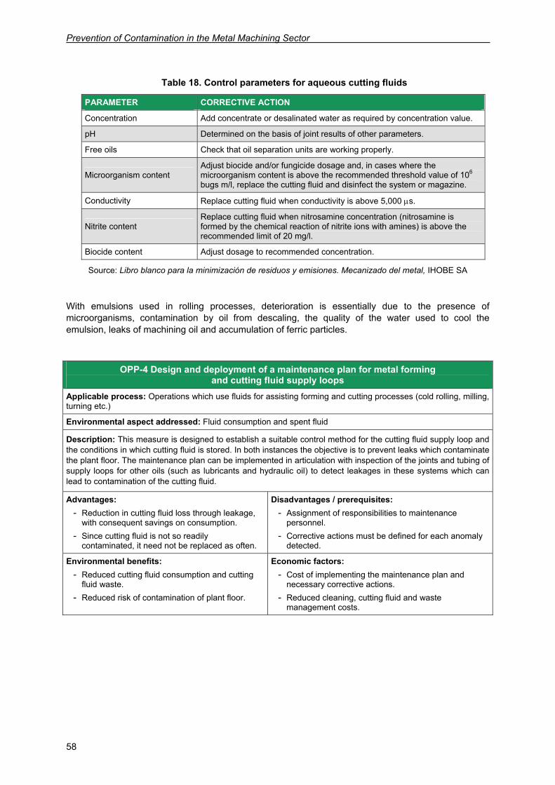
Prevention of Contamination in the Metal Machining Sector
58
Table 18. Control parameters for aqueous cutting fluids
PARAMETER CORRECTIVE ACTION
Concentration Add concentrate or desalinated water as required by concentration value.
pH Determined on the basis of joint results of other parameters.
Free oils Check that oil separation units are working properly.
Microorganism content Adjust biocide and/or fungicide dosage and, in cases where the microorganism content is above the recommended threshold value of 106 bugs m/l, replace the cutting fluid and disinfect the system or magazine.
Conductivity Replace cutting fluid when conductivity is above 5,000 μs.
Nitrite content Replace cutting fluid when nitrosamine concentration (nitrosamine is formed by the chemical reaction of nitrite ions with amines) is above the recommended limit of 20 mg/l.
Biocide content Adjust dosage to recommended concentration.
Source: Libro blanco para la minimización de residuos y emisiones. Mecanizado del metal, IHOBE SA
With emulsions used in rolling processes, deterioration is essentially due to the presence of microorganisms, contamination by oil from descaling, the quality of the water used to cool the emulsion, leaks of machining oil and accumulation of ferric particles.
OPP-4 Design and deployment of a maintenance plan for metal forming and cutting fluid supply loops
Applicable process: Operations which use fluids for assisting forming and cutting processes (cold rolling, milling, turning etc.)
Environmental aspect addressed: Fluid consumption and spent fluid
Description: This measure is designed to establish a suitable control method for the cutting fluid supply loop and the conditions in which cutting fluid is stored. In both instances the objective is to prevent leaks which contaminate the plant floor. The maintenance plan can be implemented in articulation with inspection of the joints and tubing of supply loops for other oils (such as lubricants and hydraulic oil) to detect leakages in these systems which can lead to contamination of the cutting fluid.
Advantages: - Reduction in cutting fluid loss through leakage,
with consequent savings on consumption. - Since cutting fluid is not so readily
contaminated, it need not be replaced as often.
Disadvantages / prerequisites: - Assignment of responsibilities to maintenance
personnel. - Corrective actions must be defined for each anomaly
detected.
Environmental benefits: - Reduced cutting fluid consumption and cutting
fluid waste. - Reduced risk of contamination of plant floor.
Economic factors: - Cost of implementing the maintenance plan and
necessary corrective actions. - Reduced cleaning, cutting fluid and waste
management costs.
Opportunities for preventing and reducing pollution
59
OPP-6 Disinfection of fluid loops to improve metal forming and cutting processes
Applicable process: Operations which use fluids for assisting forming and cutting processes (cold rolling, milling, turning etc.)
Environmental aspect addressed: Fluid consumption and spent fluid
Description: In addition to regular inspection of fluid quality to extend its service life, fluid must be replaced when it has lost its efficacy. At the time the spend cutting fluid is replaced, biocides and fungicides can be introduced into the supply loop to eliminate any microorganisms which may be present.
Advantages: - Reduces the risk of bacterial contamination of
the fluid and therefore extends its service life.
Disadvantages / prerequisites: - If the measure is to really help prevent pollution, the
disinfectant used must not pose any environmental risks.
- Generation of waste in the form of cleaning water.
Environmental benefits: - Reduced fluid consumption and waste
generation by around 20%.
Economic factors: - Investment in disinfection operations (cleaning water,
disinfectant and labour). - Reduced cutting fluid and waste management costs.
OPP-5 Compatibilization of cutting fluid products Applicable process: Operations which use fluids for assisting forming and cutting processes (cold rolling, milling, thread cutting etc.)
Environmental aspect addressed: Spent cutting fluid, consumption of raw materials
Description: Implementing this measure involves the introduction of two different practices. The first is to homogenize the use of process cutting fluids to use as few different compounds as possible. The second is to introduce the use of products such as lubricants and hydraulic oil which constitute a minimum contamination risk for the cutting fluid in the event of leakage. In the latter instance, floatability and miscibility are key parameters in the prevention of contamination and ease of elimination.
Advantages: - Reduced cutting fluid consumption. - Reduced storage space requirements and
simplification of raw materials stock control. - Improved efficacy of maintenance procedures.
Disadvantages / prerequisites: - The technical characteristics of the products must
first be analysed. - Effective implementation depends on the
involvement of suppliers, with their knowledge of the properties of the products.
Environmental benefits: - Reduction in spent cutting fluid waste.
Economic factors: - Costs practically nothing. - Reduced cutting fluid consumption and waste
management costs.
Examples of application: A company which makes fixtures for the automobile industry carried out a survey of the different lubricants it used in its hobbing, stippling and thread cutting activities. The survey resulted in improvements in the company’s management and storage of its oil stocks, and a 10% reduction in consumption. (Source: IHOBE)
Prevention of Contamination in the Metal Machining Sector
60
OPP-8 Optimization of workpiece orientation during machining
Applicable process: Machining operations such as thread cutting, turning, broaching etc.
Environmental aspect addressed: Cutting fluid loss by transfer to workpiece, cutting fluid consumption
Description: This measure involves positioning the workpiece during machining in such a way that the retention of cutting fluid in the piece can be reduced to a minimum, in this way reducing cutting fluid loss due to transfer.
Advantages: - Reduced transfer of cutting fluid to workpiece. - Improved efficacy of cleaning and degreasing
processes
Disadvantages / prerequisites: - Requires prior research for designing process. - May entail modifications to machine access
conditions.
Environmental benefits: - Reduced environmental damage deriving from
transfer of cutting fluid to workpieces.
Economic factors: - Reduced fluid consumption, cleaning and degreasing
costs.
OPP-9 Optimization of fluid application methods to improve metal forming and cutting
processes Applicable process: Operations which use fluids for assisting forming and cutting processes (cold rolling, milling, turning etc.)
Environmental aspect addressed: Consumption of cutting fluid, formation of oil mists
Description: This measure is designed to ensure suitable process quality and involves controlling the pressure, direction and flow rate at which cutting fluid is applied. Reducing application pressure to the minimum required for process quality and correct direction help minimize the risk of splash loss and the formation of mists.
Advantages: - Reduced cutting fluid consumption. - Reduction of approximately 50% in cutting fluid
splash loss. - Reduced risk of formation of oil mists.
Disadvantages / prerequisites: - Cutting fluid application conditions must first be
determined if the measure is to be fully effective. - Requires personnel for periodical inspection of
cutting fluid application conditions.
Environmental benefits: - Improved working environment.
Economic factors: - No additional investment required.
OPP-7 Aeration of fluids used in metal forming and cutting processes Applicable process: Operations which use cutting fluids for assisting forming and cutting processes (cold rolling, milling, turning etc.)
Environmental aspect addressed: Fluid consumption and resulting waste
Description: This measure involves the regular injection of oxygen into the fluid magazine. Aeration can occur either by the direct introduction of oxygen or by activation of the cutting fluid supply loop pump system during rest periods. In the latter case aeration is not as effective.
Advantages: - Extended service life of cutting fluid due to the
elimination of anaerobic bacteria which affect its quality.
Disadvantages / prerequisites: - Requires installation of a compressed air input.
Environmental benefits: - Reduced fluid consumption. - Reductions in waste generation of up to 10%.
Economic factors: - Compressed air circuit installation costs (these can
vary depending on the size and layout of machinery). - Reduced fluid consumption and waste management
costs.
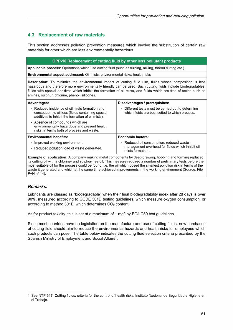
Opportunities for preventing and reducing pollution
61
4.3. Replacement of raw materials
This section addresses pollution prevention measures which involve the substitution of certain raw materials for other which are less environmentally hazardous.
OPP-10 Replacement of cutting fluid by other less pollutant products Applicable process: Operations which use cutting fluid (such as turning, milling, thread cutting etc.)
Environmental aspect addressed: Oil mists, environmental risks, health risks
Description: To minimize the environmental impact of cutting fluid use, fluids whose composition is less hazardous and therefore more environmentally friendly can be used. Such cutting fluids include biodegradables, fluids with special additives which inhibit the formation of oil mists, and fluids which are free of toxins such as amines, sulphur, chlorine, phenol, silicones.
Advantages: - Reduced incidence of oil mists formation and,
consequently, oil loss (fluids containing special additives to inhibit the formation of oil mists).
- Absence of compounds which are environmentally hazardous and present health risks, in terms both of process and waste.
Disadvantages / prerequisites: - Different tests must be carried out to determine
which fluids are best suited to which process.
Environmental benefits: - Improved working environment. - Reduced pollution load of waste generated.
Economic factors: - Reduced oil consumption, reduced waste
management overhead for fluids which inhibit oil mists formation.
Example of application: A company making metal components by deep drawing, hobbing and forming replaced its cutting oil with a chlorine- and sulphur-free oil. This measure required a number of preliminary tests before the most suitable oil for the process could be found, i.e. the oil which posed the smallest pollution risk in terms of the waste it generated and which at the same time achieved improvements in the working environment (Source: File P+N nº 14).
Remarks:
Lubricants are classed as “biodegradable” when their final biodegradability index after 28 days is over 90%, measured according to OCDE 301D testing guidelines, which measure oxygen consumption, or according to method 301B, which determines CO2 content. As for product toxicity, this is set at a maximum of 1 mg/l by EC/LC50 test guidelines. Since most countries have no legislation on the manufacture and use of cutting fluids, new purchases of cutting fluid should aim to reduce the environmental hazards and health risks for employees which such products can pose. The table below indicates the cutting fluid selection criteria prescribed by the Spanish Ministry of Employment and Social Affairs1.
1 See NTP 317: Cutting fluids: criteria for the control of health risks, Instituto Nacional de Seguridad e Higiene en
el Trabajo.
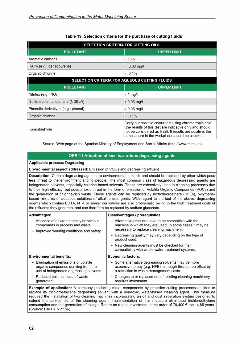
Prevention of Contamination in the Metal Machining Sector
62
Table 19. Selection criteria for the purchase of cutting fluids
SELECTION CRITERIA FOR CUTTING OILS
POLLUTANT UPPER LIMIT
Aromatic carbons < 10%
HAPs (e.g.: benzopyrene) < 0.03 mg/l
Organic chlorine < 0.1%
SELECTION CRITERIA FOR AQUEOUS CUTTING FLUIDS
POLLUTANT UPPER LIMIT
Nitrites (e.g.: NO2-) < 1 mg/l
N-nitrosodiethanolamine (NDELA) < 0.03 mg/l
Phenolic derivatives (e.g.: phenol) < 0.05 mg/l
Organic chlorine < 0.1%
Formaldehyde
Carry out positive colour test using chromotropic acid (the results of this test are indicative only and should not be considered as final). If results are positive, the atmosphere in the workplace should be checked.
Source: Web page of the Spanish Ministry of Employment and Social Affairs (http://www.mtas.es)
OPP-11 Adoption of less hazardous degreasing agents Applicable process: Degreasing
Environmental aspect addressed: Emission of VOCs and degreasing effluent
Description: Certain degreasing agents are environmental hazards and should be replaced by other which pose less threat to the environment and to people. The most common class of hazardous degreasing agents are halogenated solvents, especially chlorine-based solvents. These are extensively used in cleaning processes due to their high efficacy, but pose a toxic threat in the form of emission of Volatile Organic Compounds (VOCs) and the generation of chlorine-rich waste. These agents can be replaced by hydrofluoroethers (HFEs), p-cymene-based mixtures or aqueous solutions of alkaline detergents. With regard to the last of the above, degreasing agents which contain EDTA, NTA or similar derivatives are also problematic owing to the high treatment costs of the effluents they generate, and can therefore be replaced by sodium gluconate.
Advantages: - Absence of environmentally hazardous
compounds in process and waste. - Improved working conditions and safety
Disadvantages / prerequisites: - Alternative products have to be compatible with the
machine in which they are used. In some cases it may be necessary to replace cleaning machinery.
- Degreasing quality may vary depending on the type of product used.
- New cleaning agents must be checked for their compatibility with waste water treatment systems.
Environmental benefits: - Elimination of emissions of volatile
organic compounds deriving from the use of halogenated degreasing solvents.
- Reduced pollution load of waste generated.
Economic factors: - Some alternative degreasing solvents may be more
expensive to buy (e.g. HFE), although this can be offset by a reduction in waste management costs.
- Changes to or replacement of existing cleaning machinery requires investment.
Example of application: A company producing metal components by precision-cutting processes decided to replace its trichloroethylene degreasing solvent with a non-toxic, water-based cleaning agent. This measure required the installation of two cleaning machines incorporating an oil and dust separation system designed to extend the service life of the cleaning agent. Implementation of this measure eliminated trichloroethylene consumption and the generation of sludge. Return on a total investment in the order of 79,400 € took 4,85 years. (Source: File P+ N nº 56).
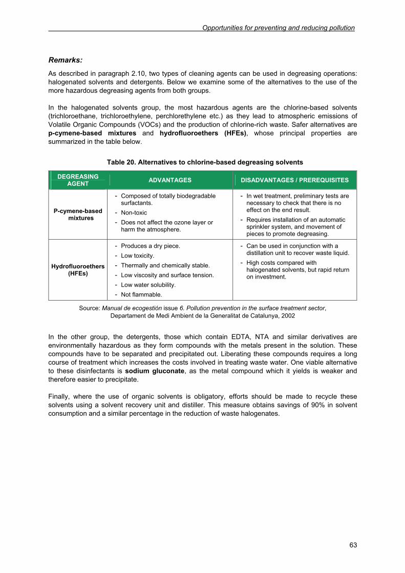
Opportunities for preventing and reducing pollution
63
Remarks:
As described in paragraph 2.10, two types of cleaning agents can be used in degreasing operations: halogenated solvents and detergents. Below we examine some of the alternatives to the use of the more hazardous degreasing agents from both groups. In the halogenated solvents group, the most hazardous agents are the chlorine-based solvents (trichloroethane, trichloroethylene, perchlorethylene etc.) as they lead to atmospheric emissions of Volatile Organic Compounds (VOCs) and the production of chlorine-rich waste. Safer alternatives are p-cymene-based mixtures and hydrofluoroethers (HFEs), whose principal properties are summarized in the table below.
Table 20. Alternatives to chlorine-based degreasing solvents
DEGREASING AGENT ADVANTAGES DISADVANTAGES / PREREQUISITES
P-cymene-based mixtures
- Composed of totally biodegradable surfactants.
- Non-toxic - Does not affect the ozone layer or
harm the atmosphere.
- In wet treatment, preliminary tests are necessary to check that there is no effect on the end result.
- Requires installation of an automatic sprinkler system, and movement of pieces to promote degreasing.
Hydrofluoroethers (HFEs)
- Produces a dry piece. - Low toxicity. - Thermally and chemically stable. - Low viscosity and surface tension. - Low water solubility. - Not flammable.
- Can be used in conjunction with a distillation unit to recover waste liquid.
- High costs compared with halogenated solvents, but rapid return on investment.
Source: Manual de ecogestión issue 6. Pollution prevention in the surface treatment sector, Departament de Medi Ambient de la Generalitat de Catalunya, 2002
In the other group, the detergents, those which contain EDTA, NTA and similar derivatives are environmentally hazardous as they form compounds with the metals present in the solution. These compounds have to be separated and precipitated out. Liberating these compounds requires a long course of treatment which increases the costs involved in treating waste water. One viable alternative to these disinfectants is sodium gluconate, as the metal compound which it yields is weaker and therefore easier to precipitate. Finally, where the use of organic solvents is obligatory, efforts should be made to recycle these solvents using a solvent recovery unit and distiller. This measure obtains savings of 90% in solvent consumption and a similar percentage in the reduction of waste halogenates.
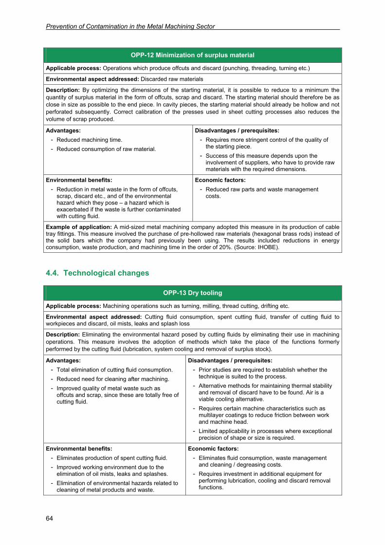
Prevention of Contamination in the Metal Machining Sector
64
4.4. Technological changes
OPP-13 Dry tooling
Applicable process: Machining operations such as turning, milling, thread cutting, drifting etc.
Environmental aspect addressed: Cutting fluid consumption, spent cutting fluid, transfer of cutting fluid to workpieces and discard, oil mists, leaks and splash loss
Description: Eliminating the environmental hazard posed by cutting fluids by eliminating their use in machining operations. This measure involves the adoption of methods which take the place of the functions formerly performed by the cutting fluid (lubrication, system cooling and removal of surplus stock).
Advantages: - Total elimination of cutting fluid consumption. - Reduced need for cleaning after machining. - Improved quality of metal waste such as
offcuts and scrap, since these are totally free of cutting fluid.
Disadvantages / prerequisites: - Prior studies are required to establish whether the
technique is suited to the process. - Alternative methods for maintaining thermal stability
and removal of discard have to be found. Air is a viable cooling alternative.
- Requires certain machine characteristics such as multilayer coatings to reduce friction between work and machine head.
- Limited applicability in processes where exceptional precision of shape or size is required.
Environmental benefits: - Eliminates production of spent cutting fluid. - Improved working environment due to the
elimination of oil mists, leaks and splashes. - Elimination of environmental hazards related to
cleaning of metal products and waste.
Economic factors: - Eliminates fluid consumption, waste management
and cleaning / degreasing costs. - Requires investment in additional equipment for
performing lubrication, cooling and discard removal functions.
OPP-12 Minimization of surplus material
Applicable process: Operations which produce offcuts and discard (punching, threading, turning etc.)
Environmental aspect addressed: Discarded raw materials
Description: By optimizing the dimensions of the starting material, it is possible to reduce to a minimum the quantity of surplus material in the form of offcuts, scrap and discard. The starting material should therefore be as close in size as possible to the end piece. In cavity pieces, the starting material should already be hollow and not perforated subsequently. Correct calibration of the presses used in sheet cutting processes also reduces the volume of scrap produced.
Advantages: - Reduced machining time. - Reduced consumption of raw material.
Disadvantages / prerequisites: - Requires more stringent control of the quality of
the starting piece. - Success of this measure depends upon the
involvement of suppliers, who have to provide raw materials with the required dimensions.
Environmental benefits: - Reduction in metal waste in the form of offcuts,
scrap, discard etc., and of the environmental hazard which they pose – a hazard which is exacerbated if the waste is further contaminated with cutting fluid.
Economic factors: - Reduced raw parts and waste management
costs.
Example of application: A mid-sized metal machining company adopted this measure in its production of cable tray fittings. This measure involved the purchase of pre-hollowed raw materials (hexagonal brass rods) instead of the solid bars which the company had previously been using. The results included reductions in energy consumption, waste production, and machining time in the order of 20%. (Source: IHOBE).
Opportunities for preventing and reducing pollution
65
Remarks:
To completely eliminate cutting fluids from machining processes measures must be taken so that the functions normally performed by the cutting fluid – evacuation of discard, lubrication and cooling – are performed by other methods. These alternative methods must comply with requirements on the thermal and mechanical stability of machinery, quality standards and tool resistance. Note too that machining at low cutting speeds increases tool wear due to adhesion and abrasion, while the high temperatures reached during high-speed cutting increase oxidation and diffusion. Successful implementation of this alternative therefore involves the selection of a tool which does not readily stick to work and attract discard, with exceptional hardness and high resistance to wear at high temperatures. Dry tooling is a developing technology, and one which therefore requires detailed examination if we are to evaluate its applicability. New developments in the design of tools and materials, such as coated tools, are extending the potential range of application of this alternative to processes in which the use of cutting fluid has hitherto been considered crucial. One example is dry gear-cutting using carbide tools, where a longer tool service life has been observed since it is cutting fluid which causes the thermal fatigue responsible for wear and tear. Besides gear cutting, dry tooling has also been successfully experimented in processes such as:
• Grey cast iron machining, a process in which the workpiece contains graphite, which acts as a lubricant. The tool has a coating of titanium nitride (TiN) and titanium (Ti).
• Hard machining instead of grinding, as the ceramic and cubic boron nitride tools currently used are affected by cutting fluid, which causes thermal fatigue problems.
• Carbon steel broaching with coated broaches, which obtain better surface quality.
• Steel machining, where results are invariably positive on condition that discard is evacuated efficiently and where no high-precision dimensions are required.
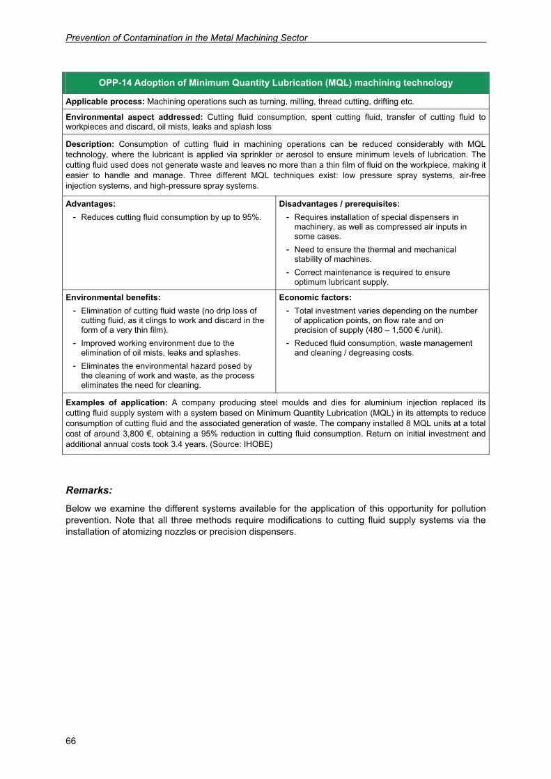
Prevention of Contamination in the Metal Machining Sector
66
Remarks:
Below we examine the different systems available for the application of this opportunity for pollution prevention. Note that all three methods require modifications to cutting fluid supply systems via the installation of atomizing nozzles or precision dispensers.
OPP-14 Adoption of Minimum Quantity Lubrication (MQL) machining technology
Applicable process: Machining operations such as turning, milling, thread cutting, drifting etc.
Environmental aspect addressed: Cutting fluid consumption, spent cutting fluid, transfer of cutting fluid to workpieces and discard, oil mists, leaks and splash loss
Description: Consumption of cutting fluid in machining operations can be reduced considerably with MQL technology, where the lubricant is applied via sprinkler or aerosol to ensure minimum levels of lubrication. The cutting fluid used does not generate waste and leaves no more than a thin film of fluid on the workpiece, making it easier to handle and manage. Three different MQL techniques exist: low pressure spray systems, air-free injection systems, and high-pressure spray systems.
Advantages: - Reduces cutting fluid consumption by up to 95%.
Disadvantages / prerequisites: - Requires installation of special dispensers in
machinery, as well as compressed air inputs in some cases.
- Need to ensure the thermal and mechanical stability of machines.
- Correct maintenance is required to ensure optimum lubricant supply.
Environmental benefits: - Elimination of cutting fluid waste (no drip loss of
cutting fluid, as it clings to work and discard in the form of a very thin film).
- Improved working environment due to the elimination of oil mists, leaks and splashes.
- Eliminates the environmental hazard posed by the cleaning of work and waste, as the process eliminates the need for cleaning.
Economic factors: - Total investment varies depending on the number
of application points, on flow rate and on precision of supply (480 – 1,500 € /unit).
- Reduced fluid consumption, waste management and cleaning / degreasing costs.
Examples of application: A company producing steel moulds and dies for aluminium injection replaced its cutting fluid supply system with a system based on Minimum Quantity Lubrication (MQL) in its attempts to reduce consumption of cutting fluid and the associated generation of waste. The company installed 8 MQL units at a total cost of around 3,800 €, obtaining a 95% reduction in cutting fluid consumption. Return on initial investment and additional annual costs took 3.4 years. (Source: IHOBE)
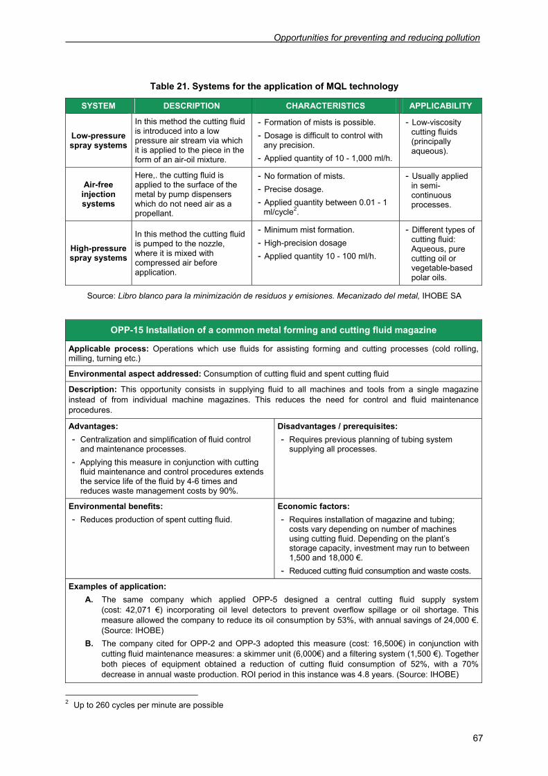
Opportunities for preventing and reducing pollution
67
Table 21. Systems for the application of MQL technology
SYSTEM DESCRIPTION CHARACTERISTICS APPLICABILITY
Low-pressure spray systems
In this method the cutting fluid is introduced into a low pressure air stream via which it is applied to the piece in the form of an air-oil mixture.
- Formation of mists is possible. - Dosage is difficult to control with
any precision. - Applied quantity of 10 - 1,000 ml/h.
- Low-viscosity cutting fluids (principally aqueous).
Air-free injection systems
Here,. the cutting fluid is applied to the surface of the metal by pump dispensers which do not need air as a propellant.
- No formation of mists. - Precise dosage. - Applied quantity between 0.01 - 1
ml/cycle2.
- Usually applied in semi-continuous processes.
High-pressure spray systems
In this method the cutting fluid is pumped to the nozzle, where it is mixed with compressed air before application.
- Minimum mist formation. - High-precision dosage - Applied quantity 10 - 100 ml/h.
- Different types of cutting fluid: Aqueous, pure cutting oil or vegetable-based polar oils.
Source: Libro blanco para la minimización de residuos y emisiones. Mecanizado del metal, IHOBE SA
OPP-15 Installation of a common metal forming and cutting fluid magazine
Applicable process: Operations which use fluids for assisting forming and cutting processes (cold rolling, milling, turning etc.)
Environmental aspect addressed: Consumption of cutting fluid and spent cutting fluid
Description: This opportunity consists in supplying fluid to all machines and tools from a single magazine instead of from individual machine magazines. This reduces the need for control and fluid maintenance procedures.
Advantages: - Centralization and simplification of fluid control
and maintenance processes. - Applying this measure in conjunction with cutting
fluid maintenance and control procedures extends the service life of the fluid by 4-6 times and reduces waste management costs by 90%.
Disadvantages / prerequisites: - Requires previous planning of tubing system
supplying all processes.
Environmental benefits: - Reduces production of spent cutting fluid.
Economic factors: - Requires installation of magazine and tubing;
costs vary depending on number of machines using cutting fluid. Depending on the plant’s storage capacity, investment may run to between 1,500 and 18,000 €.
- Reduced cutting fluid consumption and waste costs.
Examples of application: A. The same company which applied OPP-5 designed a central cutting fluid supply system
(cost: 42,071 €) incorporating oil level detectors to prevent overflow spillage or oil shortage. This measure allowed the company to reduce its oil consumption by 53%, with annual savings of 24,000 €. (Source: IHOBE)
B. The company cited for OPP-2 and OPP-3 adopted this measure (cost: 16,500€) in conjunction with cutting fluid maintenance measures: a skimmer unit (6,000€) and a filtering system (1,500 €). Together both pieces of equipment obtained a reduction of cutting fluid consumption of 52%, with a 70% decrease in annual waste production. ROI period in this instance was 4.8 years. (Source: IHOBE)
2 Up to 260 cycles per minute are possible
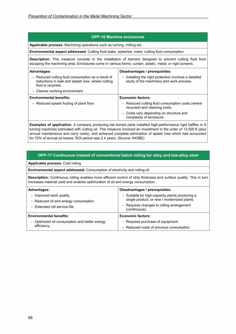
Prevention of Contamination in the Metal Machining Sector
68
OPP-16 Machine enclosures
Applicable process: Machining operations such as turning, milling etc.
Environmental aspect addressed: Cutting fluid leaks, splashes, mists; cutting fluid consumption
Description: This measure consists in the installation of barriers designed to prevent cutting fluid from escaping the machining area. Enclosures come in various forms: curtain, plastic, metal, or rigid screens.
Advantages: - Reduced cutting fluid consumption as a result of
reductions in leak and splash loss, where cutting fluid is recycled.
- Cleaner working environment.
Disadvantages / prerequisites: - Installing the right protection involves a detailed
study of the machinery and work process.
Environmental benefits: - Reduced splash fouling of plant floor.
Economic factors: - Reduced cutting fluid consumption costs (where
recycled) and cleaning costs. - Costs vary depending on structure and
complexity of enclosure.
Examples of application: A company producing bar-turned parts installed high-performance rigid baffles in 9 turning machines lubricated with cutting oil. This measure involved an investment in the order of 13,500 € (plus annual maintenance and carry costs), and achieved complete elimination of splash loss which had accounted for 70% of annual oil losses. ROI period was 2.4 years. (Source: IHOBE)
OPP-17 Continuous instead of conventional batch rolling for alloy and low-alloy steel
Applicable process: Cold rolling
Environmental aspect addressed: Consumption of electricity and rolling oil
Description: Continuous rolling enables more efficient control of strip thickness and surface quality. This in turn increases material yield and enables optimization of oil and energy consumption.
Advantages: - Improved work quality. - Reduced oil and energy consumption. - Extended roll service life.
Disadvantages / prerequisites: - Suitable for high-capacity plants producing a
single product, or new / modernized plants. - Requires changes to rolling arrangement
(continuous).
Environmental benefits: - Optimized oil consumption and better energy
efficiency.
Economic factors: - Requires purchase of equipment. - Reduced costs of previous consumption.
Opportunities for preventing and reducing pollution
69
OPP-19 Introduction of low NOX burners to reduce NOX emissions in annealing furnaces
Applicable process: Heat treatment – heat-up stage
Environmental aspect addressed: Atmospheric emissions of NOX
Description: Some burners, by reducing maximum flame temperature, high-temperature process time or oxygen availability in the combustion zone, make it possible to reduce the NOX emissions of conventional furnaces. To achieve this, the burners are designed to regulate the air-fuel mix and/or internally recycle combustion gases.
Advantages: - Reduces NOX emissions by 60%. - Reduces CO emissions by 87%. - Fuel consumption remains the same.
Disadvantages / prerequisites: - NOX emissions vary according to many factors
(furnace design, type of fuel, temperature, efficiency and maintenance of furnace), all of which must be taken into account in optimizing the efficiency of low-NOX burners.
Environmental benefits: - Reduction in gas emissions and atmospheric
pollution.
Economic factors: - Requires replacement of burners.
Remarks:
The table below shows the NO2 and CO emission levels which can be obtained by installing low-NOX burners in continuous and batch annealing furnaces.
OPP-18 Batch annealing 100% with hydrogen
Applicable process: The pre-heating stage in annealing
Environmental aspect addressed: Energy consumption
Description: After cold rolling, low alloy steel is generally annealed in a bell furnace, a time-consuming process with a cooling speed not recommended for certain types of steel. During heating, the protective atmosphere typically consists of a mixture of nitrogen and hydrogen, the hydrogen content being near inflammation point. Using a 100% hydrogen atmosphere makes annealing quicker and further reduces cooling times.
Advantages: - Reduced annealing time. - Reduced cooling time.
Disadvantages / prerequisites: - Requires change of gas environment.
Environmental benefits: - Reduced energy consumption (from 700 MJ/t in a
H2/N2 atmosphere to 422 MJ/t in a 100% hydrogen atmosphere).
Economic factors: - Reduced costs of previous consumption.
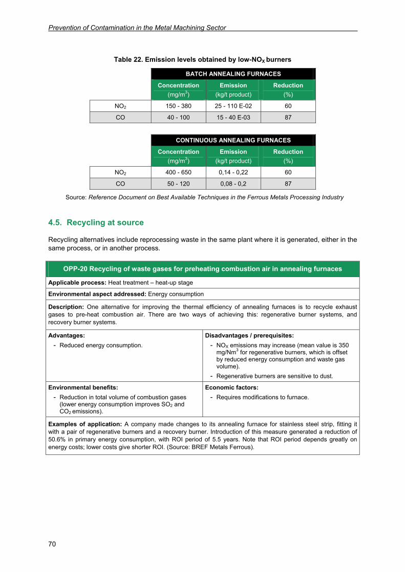
Prevention of Contamination in the Metal Machining Sector
70
Table 22. Emission levels obtained by low-NOX burners
BATCH ANNEALING FURNACES Concentration
(mg/m3) Emission
(kg/t product) Reduction
(%)
NO2 150 - 380 25 - 110 E-02 60
CO 40 - 100 15 - 40 E-03 87
CONTINUOUS ANNEALING FURNACES
Concentration (mg/m3)
Emission (kg/t product)
Reduction (%)
NO2 400 - 650 0,14 - 0,22 60
CO 50 - 120 0,08 - 0,2 87
Source: Reference Document on Best Available Techniques in the Ferrous Metals Processing Industry
4.5. Recycling at source
Recycling alternatives include reprocessing waste in the same plant where it is generated, either in the same process, or in another process.
OPP-20 Recycling of waste gases for preheating combustion air in annealing furnaces
Applicable process: Heat treatment – heat-up stage
Environmental aspect addressed: Energy consumption
Description: One alternative for improving the thermal efficiency of annealing furnaces is to recycle exhaust gases to pre-heat combustion air. There are two ways of achieving this: regenerative burner systems, and recovery burner systems.
Advantages: - Reduced energy consumption.
Disadvantages / prerequisites: - NOX emissions may increase (mean value is 350
mg/Nm3 for regenerative burners, which is offset by reduced energy consumption and waste gas volume).
- Regenerative burners are sensitive to dust.
Environmental benefits: - Reduction in total volume of combustion gases
(lower energy consumption improves SO2 and CO2 emissions).
Economic factors: - Requires modifications to furnace.
Examples of application: A company made changes to its annealing furnace for stainless steel strip, fitting it with a pair of regenerative burners and a recovery burner. Introduction of this measure generated a reduction of 50.6% in primary energy consumption, with ROI period of 5.5 years. Note that ROI period depends greatly on energy costs; lower costs give shorter ROI. (Source: BREF Metals Ferrous).
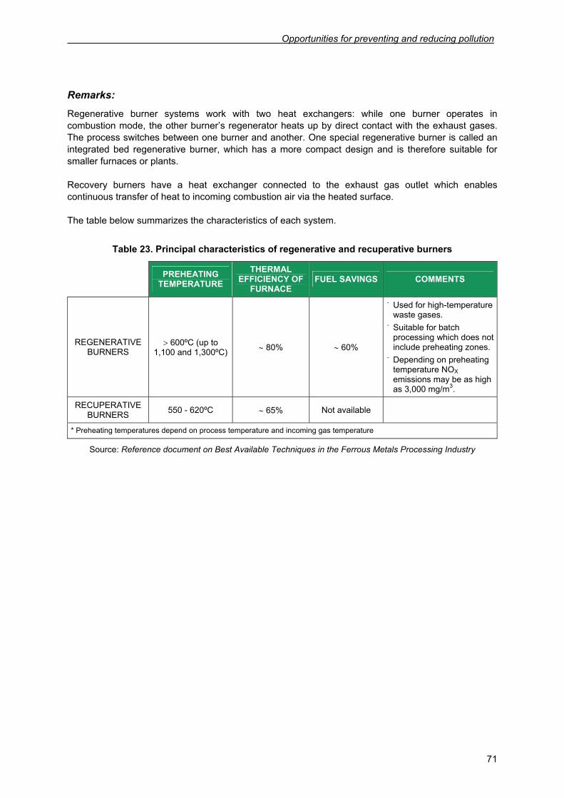
Opportunities for preventing and reducing pollution
71
Remarks:
Regenerative burner systems work with two heat exchangers: while one burner operates in combustion mode, the other burner’s regenerator heats up by direct contact with the exhaust gases. The process switches between one burner and another. One special regenerative burner is called an integrated bed regenerative burner, which has a more compact design and is therefore suitable for smaller furnaces or plants. Recovery burners have a heat exchanger connected to the exhaust gas outlet which enables continuous transfer of heat to incoming combustion air via the heated surface. The table below summarizes the characteristics of each system.
Table 23. Principal characteristics of regenerative and recuperative burners
PREHEATING TEMPERATURE
THERMAL EFFICIENCY OF
FURNACE FUEL SAVINGS COMMENTS
REGENERATIVE BURNERS
> 600ºC (up to 1,100 and 1,300ºC) ∼ 80% ∼ 60%
- Used for high-temperature waste gases.
- Suitable for batch processing which does not include preheating zones.
- Depending on preheating temperature NOX emissions may be as high as 3,000 mg/m3.
RECUPERATIVE BURNERS 550 - 620ºC ∼ 65% Not available
* Preheating temperatures depend on process temperature and incoming gas temperature
Source: Reference document on Best Available Techniques in the Ferrous Metals Processing Industry
Prevention of Contamination in the Metal Machining Sector
72
OPP-21 Reinjection of cutting fluid recovered from workpieces and discard
Applicable process: Operations which use cutting fluid (such as turning, milling, thread cutting etc.)
Environmental aspect addressed: Consumption of cutting fluid, transfer of cutting fluid to work and discard
Description: This method consists in recovering cutting fluid drip loss from work and discard using e.g. collectors to reinject recovered fluid into the supply loop via a pump and tubing system. Recovery efficiency increases in proportion to drip time.
Advantages: - Reduced cutting fluid consumption. - Reduction in the degreasing and cleaning
requirements of pieces
Disadvantages / prerequisites: - Pumps must be protected against corrosive or
chemical effects of cutting fluid.
Environmental benefits: - Reduced cutting fluid waste. - Reduced cutting fluid transfer to work and
discard.
Economic factors: - Requires installation of a pump and tubing system
to recirculate the fluid. - Reduced fluid consumption, waste management
and cleaning / degreasing costs.
Examples of application: A. A company producing parts and components for the automobile industry applied this measure in an
endeavour to reduce drip loss of cutting fluid from discard collectors. Initial investment of 15,000 € included construction of a magazine, plus energy and maintenance costs. ROI was 11 months, as implementation involved a 60% reduction in cutting oil consumption and a reduction of 33% in waste management costs. (Source: COMESA)
B. The same company as cited for OPP-16 installed collectors to recover aqueous cutting fluid from workpieces. Implementation cost 3,060 € for the installation of 17 collectors, with an annual reduction in cutting fluid consumption and cleaning costs of 1,188 €. ROI period in this particular instance was 3.4 years. (Source: IHOBE)
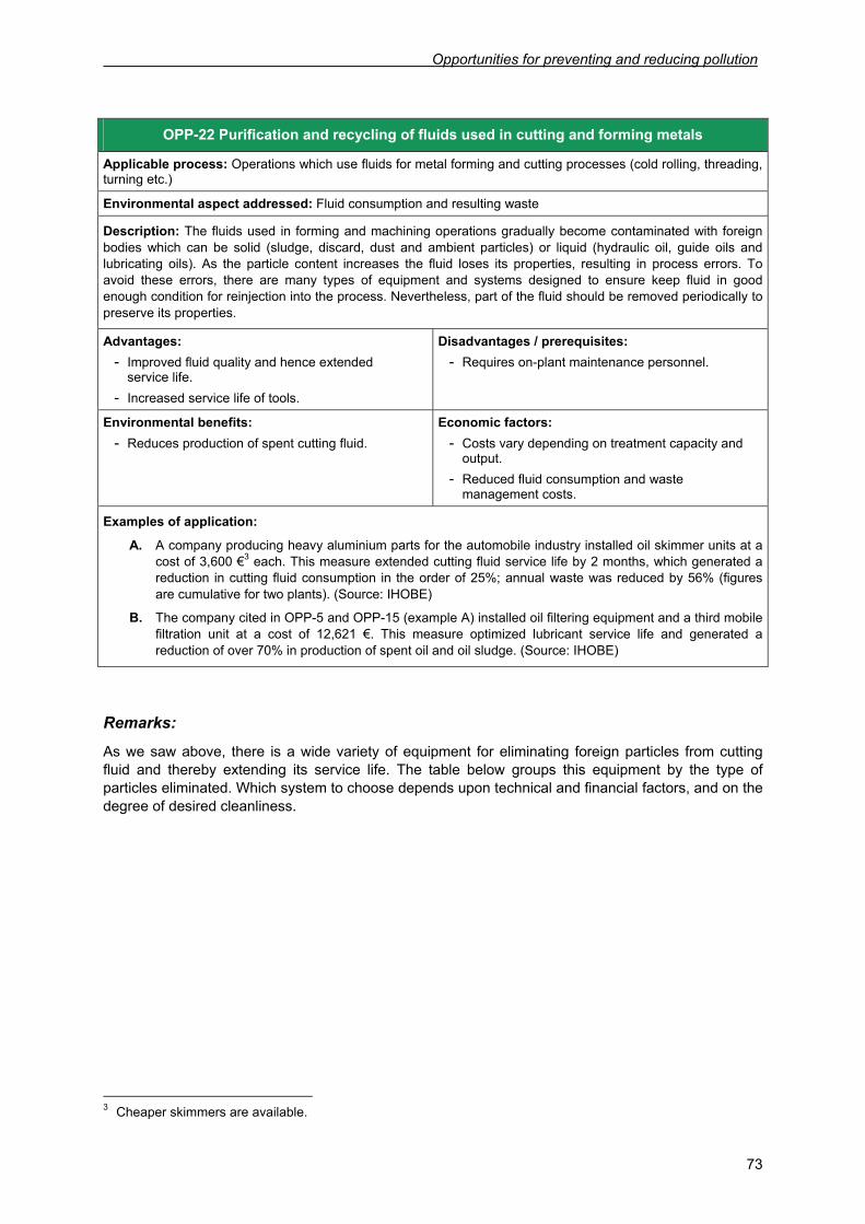
Opportunities for preventing and reducing pollution
73
Remarks:
As we saw above, there is a wide variety of equipment for eliminating foreign particles from cutting fluid and thereby extending its service life. The table below groups this equipment by the type of particles eliminated. Which system to choose depends upon technical and financial factors, and on the degree of desired cleanliness.
3 Cheaper skimmers are available.
OPP-22 Purification and recycling of fluids used in cutting and forming metals
Applicable process: Operations which use fluids for metal forming and cutting processes (cold rolling, threading, turning etc.)
Environmental aspect addressed: Fluid consumption and resulting waste
Description: The fluids used in forming and machining operations gradually become contaminated with foreign bodies which can be solid (sludge, discard, dust and ambient particles) or liquid (hydraulic oil, guide oils and lubricating oils). As the particle content increases the fluid loses its properties, resulting in process errors. To avoid these errors, there are many types of equipment and systems designed to ensure keep fluid in good enough condition for reinjection into the process. Nevertheless, part of the fluid should be removed periodically to preserve its properties.
Advantages: - Improved fluid quality and hence extended
service life. - Increased service life of tools.
Disadvantages / prerequisites: - Requires on-plant maintenance personnel.
Environmental benefits: - Reduces production of spent cutting fluid.
Economic factors: - Costs vary depending on treatment capacity and
output. - Reduced fluid consumption and waste
management costs.
Examples of application: A. A company producing heavy aluminium parts for the automobile industry installed oil skimmer units at a
cost of 3,600 €3 each. This measure extended cutting fluid service life by 2 months, which generated a reduction in cutting fluid consumption in the order of 25%; annual waste was reduced by 56% (figures are cumulative for two plants). (Source: IHOBE)
B. The company cited in OPP-5 and OPP-15 (example A) installed oil filtering equipment and a third mobile filtration unit at a cost of 12,621 €. This measure optimized lubricant service life and generated a reduction of over 70% in production of spent oil and oil sludge. (Source: IHOBE)
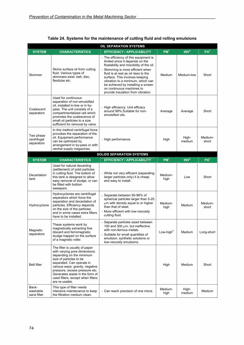
Prevention of Contamination in the Metal Machining Sector
74
Table 24. Systems for the maintenance of cutting fluid and rolling emulsions
OIL SEPARATION SYSTEMS SYSTEM CHARACTERISTICS EFFICIENCY / APPLICABILITY PM1 INV2 PA3
Skimmer
Skims surface oil from cutting fluid. Various types of skimmers exist: belt, disc, flexitube etc.
- The efficiency of this equipment is limited since it depends on the floatability and miscibility of the oil.
- Skimming is more efficient when fluid is at rest as oil rises to the surface. This involves keeping vibration to a minimum, which can be achieved by installing a screen on continuous machines to provide insulation from vibration.
Medium Medium-low Short
Coalescent separators
Used for continuous separation of non-emulsified oil, installed in-line or in by-pass. The unit consists of a compartmentalized cell which promotes the coalescence of small oil particles to a size sufficient for removal by valve.
- High efficiency. Unit efficacy around 99%.Suitable for non-emulsified oils.
Average Average Short
Two phase centrifugal separators
In this method centrifugal force provokes the separation of the oil. Equipment performance can be optimized by arrangement in by-pass or with central supply magazines.
- High performance. High High-medium
Medium-short
SOLIDS SEPARATION SYSTEMS SYSTEM CHARACTERISTICS EFFICIENCY / APPLICABILITY PM1 INV2 PA3
Decantation tank
Used for natural decanting (settlement) of solid particles in cutting fluid. The bottom of this tank is designed to allow easy removal of sludge, or can be fitted with bottom sweepers.
- While not very efficient (separating larger particles only) it is cheap and easy to install.
Medium-high Low Short
Hydrocyclone
Hydrocyclones are centrifugal separators which force the separation and decantation of particles. Efficiency depends on the size of the particles, and in some cases extra filters have to be installed.
- Separate between 95-98% of spherical particles larger than 5-20 μm with density equal to or higher than that of steel.
- More efficient with low-viscosity cutting fluid.
Medium-high Medium Medium-
short
Magnetic separators
These systems work by magnetically extracting fine discard and ferromagnetic sludge trapped on the surface of a magnetic roller.
- Separate particles sized between 100 and 300 μm, but ineffective with non-ferrous metals.
- Suitable for small quantities of emulsion, synthetic solutions or low-viscosity emulsions.
Low-high4 Medium Long-short
Belt filter
The filter is usually of paper with varying pore dimensions depending on the minimum size of particles to be separated. Can operate in various ways: gravity, negative pressure, excess pressure etc. Generates waste in the form of used filters, except when filters are re-usable.
High Medium Short
Back-washable sand filter
This type of filter needs intensive maintenance to keep the filtration medium clean.
- Can reach precision of one micra. Medium-high
High-medium Medium
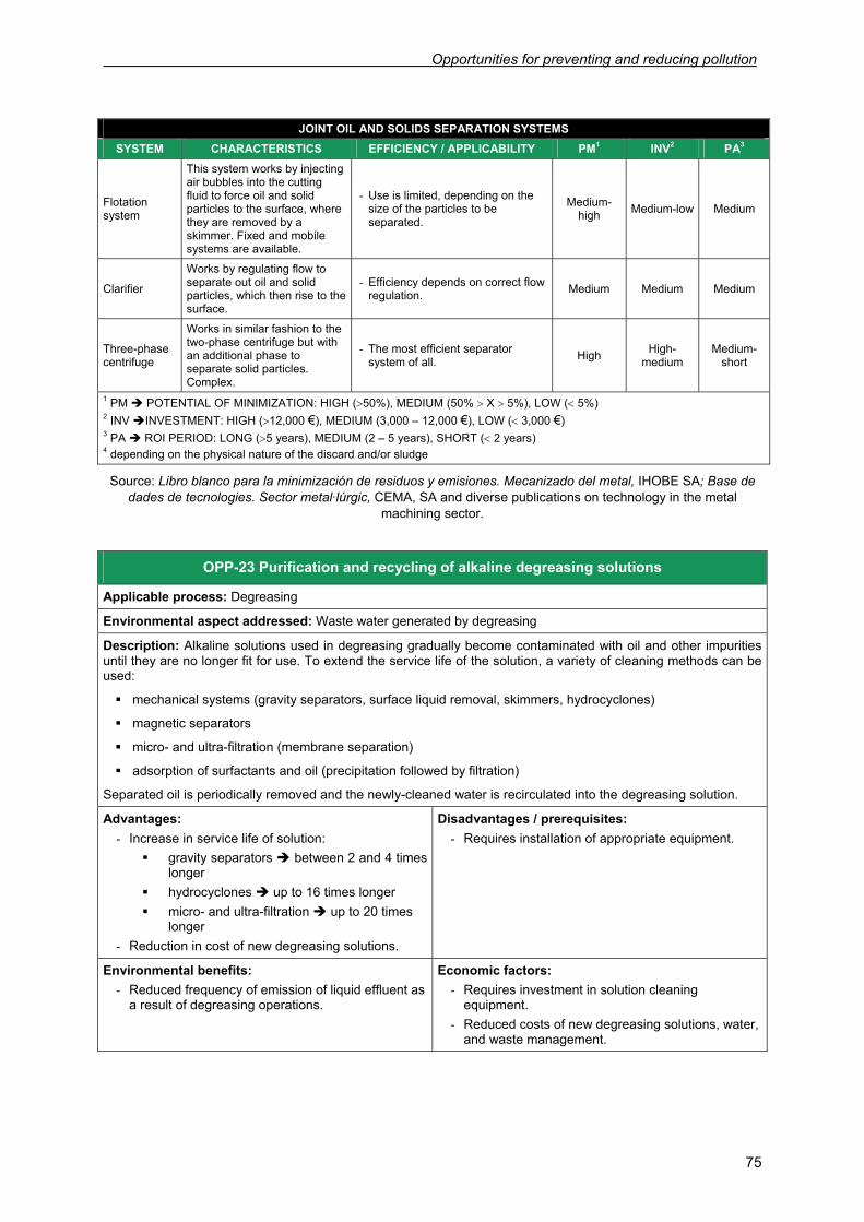
Opportunities for preventing and reducing pollution
75
JOINT OIL AND SOLIDS SEPARATION SYSTEMS SYSTEM CHARACTERISTICS EFFICIENCY / APPLICABILITY PM1 INV2 PA3
Flotation system
This system works by injecting air bubbles into the cutting fluid to force oil and solid particles to the surface, where they are removed by a skimmer. Fixed and mobile systems are available.
- Use is limited, depending on the size of the particles to be separated.
Medium-high Medium-low Medium
Clarifier
Works by regulating flow to separate out oil and solid particles, which then rise to the surface.
- Efficiency depends on correct flow regulation. Medium Medium Medium
Three-phase centrifuge
Works in similar fashion to the two-phase centrifuge but with an additional phase to separate solid particles. Complex.
- The most efficient separator system of all. High High-
medium Medium-
short
1 PM POTENTIAL OF MINIMIZATION: HIGH (>50%), MEDIUM (50% > X > 5%), LOW (< 5%) 2 INV INVESTMENT: HIGH (>12,000 €), MEDIUM (3,000 – 12,000 €), LOW (< 3,000 €) 3 PA ROI PERIOD: LONG (>5 years), MEDIUM (2 – 5 years), SHORT (< 2 years) 4 depending on the physical nature of the discard and/or sludge
Source: Libro blanco para la minimización de residuos y emisiones. Mecanizado del metal, IHOBE SA; Base de dades de tecnologies. Sector metal·lúrgic, CEMA, SA and diverse publications on technology in the metal
machining sector.
OPP-23 Purification and recycling of alkaline degreasing solutions
Applicable process: Degreasing
Environmental aspect addressed: Waste water generated by degreasing
Description: Alkaline solutions used in degreasing gradually become contaminated with oil and other impurities until they are no longer fit for use. To extend the service life of the solution, a variety of cleaning methods can be used: mechanical systems (gravity separators, surface liquid removal, skimmers, hydrocyclones)
magnetic separators
micro- and ultra-filtration (membrane separation)
adsorption of surfactants and oil (precipitation followed by filtration)
Separated oil is periodically removed and the newly-cleaned water is recirculated into the degreasing solution.
Advantages: - Increase in service life of solution:
gravity separators between 2 and 4 times longer
hydrocyclones up to 16 times longer micro- and ultra-filtration up to 20 times
longer - Reduction in cost of new degreasing solutions.
Disadvantages / prerequisites: - Requires installation of appropriate equipment.
Environmental benefits: - Reduced frequency of emission of liquid effluent as
a result of degreasing operations.
Economic factors: - Requires investment in solution cleaning
equipment. - Reduced costs of new degreasing solutions, water,
and waste management.
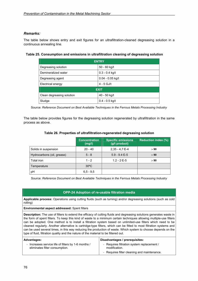
Prevention of Contamination in the Metal Machining Sector
76
Remarks:
The table below shows entry and exit figures for an ultrafiltration-cleaned degreasing solution in a continuous annealing line.
Table 25. Consumption and emissions in ultrafiltration cleaning of degreasing solution
ENTRY
Degreasing solution 50 - 60 kg/t
Demineralized water 0.3 - 0.4 kg/t
Degreasing agent 0.04 - 0.05 kg/t
Electrical energy 4 - 5 GJ/t
EXIT
Clean degreasing solution 40 - 50 kg/t
Sludge 0.4 - 0.5 kg/t
Source: Reference Document on Best Available Techniques in the Ferrous Metals Processing Industry
The table below provides figures for the degreasing solution regenerated by ultrafiltration in the same process as above.
Table 26. Properties of ultrafiltration-regenerated degreasing solution
Concentration (mg/l)
Specific emissions (g/t product)
Reduction index (%)
Solids in suspension 20 - 40 2,35 - 4,7·E-4 > 90
Hydrocarbons (oil, grease) 5 - 8 5.9 - 9.4·E-5 > 90
Total iron 1 - 2 1.2 - 2·E-5 > 90
Temperature 30ºC
pH 6,5 - 9,5
Source: Reference Document on Best Available Techniques in the Ferrous Metals Processing Industry
OPP-24 Adoption of re-usable filtration media
Applicable process: Operations using cutting fluids (such as turning) and/or degreasing solutions (such as cold rolling)
Environmental aspect addressed: Spent filters
Description: The use of filters to extend the efficacy of cutting fluids and degreasing solutions generates waste in the form of spent filters. To keep this kind of waste to a minimum certain techniques allowing multiple-use filters can be adopted. One method is to install a filtration system based on unlimited-use filters which need to be cleaned regularly. Another alternative is cartridge-type filters, which can be fitted to most filtration systems and can be used several times, in this way reducing the production of waste. Which system to choose depends on the type of fluid, filtration quality and the nature of the material to be filtered out.
Advantages: - Increases service life of filters by 1-6 months /
eliminates filter consumption.
Disadvantages / prerequisites: - Requires filtration system replacement /
modification. - Requires filter cleaning and maintenance.
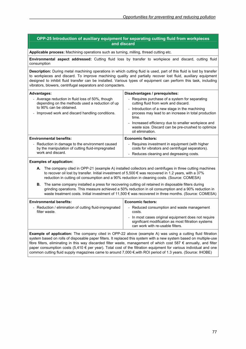
Opportunities for preventing and reducing pollution
77
Environmental benefits: - Reduction / elimination of cutting fluid-impregnated
filter waste.
Economic factors: - Reduced consumption and waste management
costs. - In most cases original equipment does not require
significant modification as most filtration systems can work with re-usable filters.
Example of application: The company cited in OPP-22 above (example A) was using a cutting fluid filtration system based on rolls of disposable paper filters. It replaced this system with a new system based on multiple-use fibre filters, eliminating in this way discarded filter waste, management of which cost 587 € annually, and filter paper consumption costs (5,410 € per year). Total cost of the filtration equipment for various individual and one common cutting fluid supply magazines came to around 7,000 €,with ROI period of 1.3 years. (Source: IHOBE)
OPP-25 Introduction of auxiliary equipment for separating cutting fluid from workpieces and discard
Applicable process: Machining operations such as turning, milling, thread cutting etc.
Environmental aspect addressed: Cutting fluid loss by transfer to workpiece and discard, cutting fluid consumption
Description: During metal machining operations in which cutting fluid is used, part of this fluid is lost by transfer to workpieces and discard. To improve machining quality and partially recover lost fluid, auxiliary equipment designed to inhibit fluid transfer can be installed. Various types of equipment can perform this task, including vibrators, blowers, centrifugal separators and compacters.
Advantages: - Average reduction in fluid loss of 50%, though
depending on the methods used a reduction of up to 90% can be obtained.
- Improved work and discard handling conditions.
Disadvantages / prerequisites: - Requires purchase of a system for separating
cutting fluid from work and discard. - Introduction of a new stage in the machining
process may lead to an increase in total production time.
- Increased efficiency due to smaller workpiece and waste size. Discard can be pre-crushed to optimize oil elimination.
Environmental benefits: - Reduction in damage to the environment caused
by the manipulation of cutting fluid-impregnated work and discard.
Economic factors: - Requires investment in equipment (with higher
costs for vibrators and centrifugal separators). - Reduces cleaning and degreasing costs.
Examples of application:
A. The company cited in OPP-21 (example A) installed collectors and centrifuges in three cutting machines to recover oil lost by transfer. Initial investment of 5,500 € was recovered in 1.2 years, with a 37% reduction in cutting oil consumption and a 90% reduction in cleaning costs. (Source: COMESA)
B. The same company installed a press for recovering cutting oil retained in disposable filters during grinding operations. This measure achieved a 50% reduction in oil consumption and a 90% reduction in waste treatment costs. Initial investment of 11,500 € was recovered in three months. (Source: COMESA)
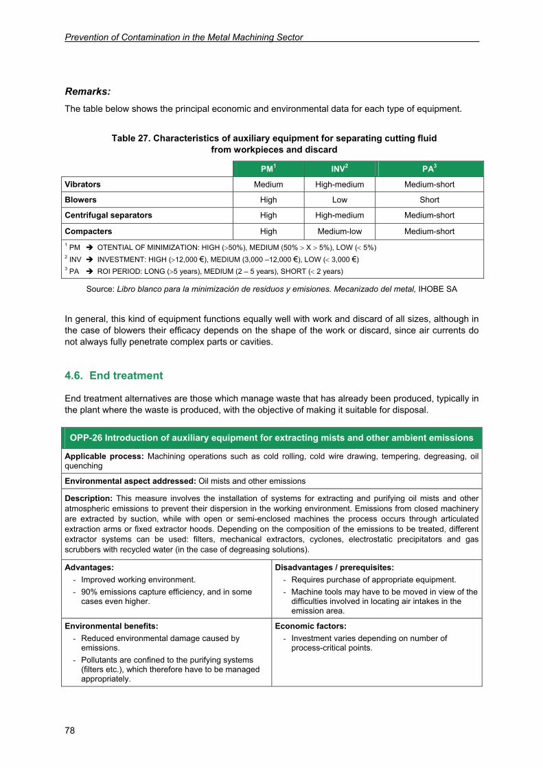
Prevention of Contamination in the Metal Machining Sector
78
Remarks: The table below shows the principal economic and environmental data for each type of equipment.
Table 27. Characteristics of auxiliary equipment for separating cutting fluid from workpieces and discard
PM1 INV2 PA3
Vibrators Medium High-medium Medium-short
Blowers High Low Short
Centrifugal separators High High-medium Medium-short Compacters High Medium-low Medium-short 1 PM OTENTIAL OF MINIMIZATION: HIGH (>50%), MEDIUM (50% > X > 5%), LOW (< 5%) 2 INV INVESTMENT: HIGH (>12,000 €), MEDIUM (3,000 –12,000 €), LOW (< 3,000 €) 3 PA ROI PERIOD: LONG (>5 years), MEDIUM (2 – 5 years), SHORT (< 2 years)
Source: Libro blanco para la minimización de residuos y emisiones. Mecanizado del metal, IHOBE SA
In general, this kind of equipment functions equally well with work and discard of all sizes, although in the case of blowers their efficacy depends on the shape of the work or discard, since air currents do not always fully penetrate complex parts or cavities.
4.6. End treatment
End treatment alternatives are those which manage waste that has already been produced, typically in the plant where the waste is produced, with the objective of making it suitable for disposal.
OPP-26 Introduction of auxiliary equipment for extracting mists and other ambient emissions
Applicable process: Machining operations such as cold rolling, cold wire drawing, tempering, degreasing, oil quenching
Environmental aspect addressed: Oil mists and other emissions
Description: This measure involves the installation of systems for extracting and purifying oil mists and other atmospheric emissions to prevent their dispersion in the working environment. Emissions from closed machinery are extracted by suction, while with open or semi-enclosed machines the process occurs through articulated extraction arms or fixed extractor hoods. Depending on the composition of the emissions to be treated, different extractor systems can be used: filters, mechanical extractors, cyclones, electrostatic precipitators and gas scrubbers with recycled water (in the case of degreasing solutions).
Advantages: - Improved working environment. - 90% emissions capture efficiency, and in some
cases even higher.
Disadvantages / prerequisites: - Requires purchase of appropriate equipment. - Machine tools may have to be moved in view of the
difficulties involved in locating air intakes in the emission area.
Environmental benefits: - Reduced environmental damage caused by
emissions. - Pollutants are confined to the purifying systems
(filters etc.), which therefore have to be managed appropriately.
Economic factors: - Investment varies depending on number of
process-critical points.
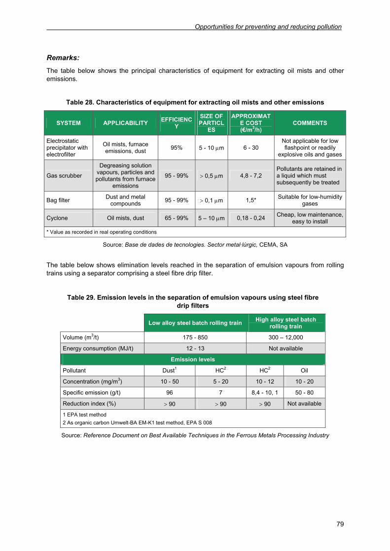
Opportunities for preventing and reducing pollution
79
Remarks:
The table below shows the principal characteristics of equipment for extracting oil mists and other emissions.
Table 28. Characteristics of equipment for extracting oil mists and other emissions
SYSTEM APPLICABILITY EFFICIENCY
SIZE OF PARTICL
ES
APPROXIMATE COST (€/m3/h)
COMMENTS
Electrostatic precipitator with electrofilter
Oil mists, furnace emissions, dust 95% 5 - 10 μm 6 - 30
Not applicable for low flashpoint or readily
explosive oils and gases
Gas scrubber
Degreasing solution vapours, particles and pollutants from furnace
emissions
95 - 99% > 0,5 μm 4,8 - 7,2 Pollutants are retained in a liquid which must subsequently be treated
Bag filter Dust and metal compounds 95 - 99% > 0,1 μm 1,5* Suitable for low-humidity
gases
Cyclone Oil mists, dust 65 - 99% 5 – 10 μm 0,18 - 0,24 Cheap, low maintenance, easy to install
* Value as recorded in real operating conditions
Source: Base de dades de tecnologies. Sector metal·lúrgic, CEMA, SA
The table below shows elimination levels reached in the separation of emulsion vapours from rolling trains using a separator comprising a steel fibre drip filter.
Table 29. Emission levels in the separation of emulsion vapours using steel fibre drip filters
Low alloy steel batch rolling train High alloy steel batch rolling train
Volume (m3/t) 175 - 850 300 – 12,000
Energy consumption (MJ/t) 12 - 13 Not available
Emission levels
Pollutant Dust1 HC2 HC2 Oil
Concentration (mg/m3) 10 - 50 5 - 20 10 - 12 10 - 20
Specific emission (g/t) 96 7 8,4 - 10, 1 50 - 80
Reduction index (%) > 90 > 90 > 90 Not available
1 EPA test method 2 As organic carbon Umwelt-BA EM-K1 test method, EPA S 008
Source: Reference Document on Best Available Techniques in the Ferrous Metals Processing Industry
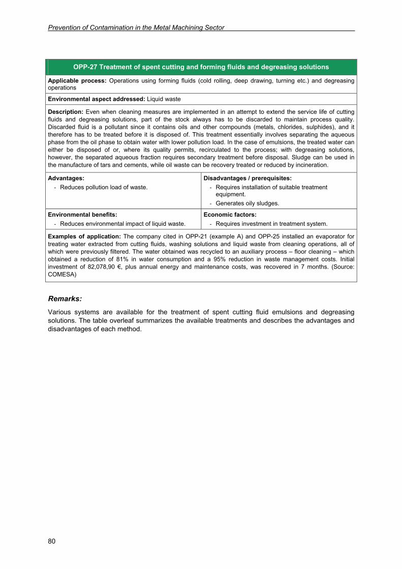
Prevention of Contamination in the Metal Machining Sector
80
Remarks:
Various systems are available for the treatment of spent cutting fluid emulsions and degreasing solutions. The table overleaf summarizes the available treatments and describes the advantages and disadvantages of each method.
OPP-27 Treatment of spent cutting and forming fluids and degreasing solutions
Applicable process: Operations using forming fluids (cold rolling, deep drawing, turning etc.) and degreasing operations
Environmental aspect addressed: Liquid waste
Description: Even when cleaning measures are implemented in an attempt to extend the service life of cutting fluids and degreasing solutions, part of the stock always has to be discarded to maintain process quality. Discarded fluid is a pollutant since it contains oils and other compounds (metals, chlorides, sulphides), and it therefore has to be treated before it is disposed of. This treatment essentially involves separating the aqueous phase from the oil phase to obtain water with lower pollution load. In the case of emulsions, the treated water can either be disposed of or, where its quality permits, recirculated to the process; with degreasing solutions, however, the separated aqueous fraction requires secondary treatment before disposal. Sludge can be used in the manufacture of tars and cements, while oil waste can be recovery treated or reduced by incineration.
Advantages: - Reduces pollution load of waste.
Disadvantages / prerequisites: - Requires installation of suitable treatment
equipment. - Generates oily sludges.
Environmental benefits: - Reduces environmental impact of liquid waste.
Economic factors: - Requires investment in treatment system.
Examples of application: The company cited in OPP-21 (example A) and OPP-25 installed an evaporator for treating water extracted from cutting fluids, washing solutions and liquid waste from cleaning operations, all of which were previously filtered. The water obtained was recycled to an auxiliary process – floor cleaning – which obtained a reduction of 81% in water consumption and a 95% reduction in waste management costs. Initial investment of 82,078,90 €, plus annual energy and maintenance costs, was recovered in 7 months. (Source: COMESA)
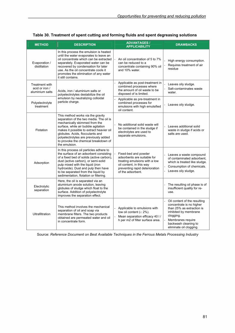
Opportunities for preventing and reducing pollution
81
Table 30. Treatment of spent cutting and forming fluids and spent degreasing solutions
METHOD DESCRIPTION ADVANTAGES / APPLICABILITY DRAWBACKS
Evaporation / distillation
In this process the emulsion is heated until the water evaporates to leave an oil concentrate which can be extracted separately. Evaporated water can be recovered by condensation for later use. As the oil concentrate cools it promotes the elimination of any water it still contains.
- An oil concentration of 5 to 7% can be reduced to a concentrate containing 90% oil and 10% water.
- High energy consumption. - Requires treatment of air
residue
Treatment with acid or iron /
aluminium salts
- Applicable as post-treatment in combined processes where the amount of oil waste to be disposed of is limited.
- Leaves oily sludge. - Salt-contaminates waste
water.
Polyelectrolyte treatment
Acids, iron / aluminium salts or polyelectrolytes destabilize the oil emulsion by neutralizing colloidal particle charge.
- Applicable as pre-treatment in combined processes for emulsions with high emulsified oil content.
- Leaves oily sludge.
Flotation
This method works via the gravity separation of the two media. The oil is mechanically skimmed from the surface, while air bubble agitation makes it possible to extract heavier oil globules. Acids, flocculants and polyelectrolytes are previously added to provoke the chemical breakdown of the emulsion.
- No additional solid waste will be contained in the sludge if electrolytes are used to separate emulsions.
- Leaves additional solid waste in sludge if acids or salts are used.
Adsorption
In this process oil particles adhere to the surface of an adsorbent consisting of a fixed bed of solids (active carbon), dust (active carbon), or semi-solid pulp mixed with the liquid (iron hydroxide). Dust and pulp then have to be separated from the liquid by sedimentation, flotation or filtering.
- Fixed-bed and powder adsorbents are suitable for treating emulsions with a low oil content, in this way preventing rapid deterioration of the adsorbent.
- Leaves a waste compound of contaminated adsorbent, which is treated like sludge.
- Consumption of chemicals. - Leaves oily sludge.
Electrolytic separation
Here, the oil is separated via an aluminium anode solution, leaving globules of sludge which float to the surface. Addition of polyelectrolyte improves the separation effect.
- The resulting oil phase is of
insufficient quality for re-use.
Ultrafiltration
This method involves the mechanical separation of oil and soap via membrane filters. The two products obtained are permeated water and oil in concentrate form.
- Applicable to emulsions with low oil content (< 2%).
- Mean separation efficacy 40 l / h per m2 of filter surface area.
- Oil content of the resulting concentrate is no higher than 25% as extraction is inhibited by membrane clogging.
- Membranes require backwash cleaning to eliminate oil clogging.
Source: Reference Document on Best Available Techniques in the Ferrous Metals Processing Industry

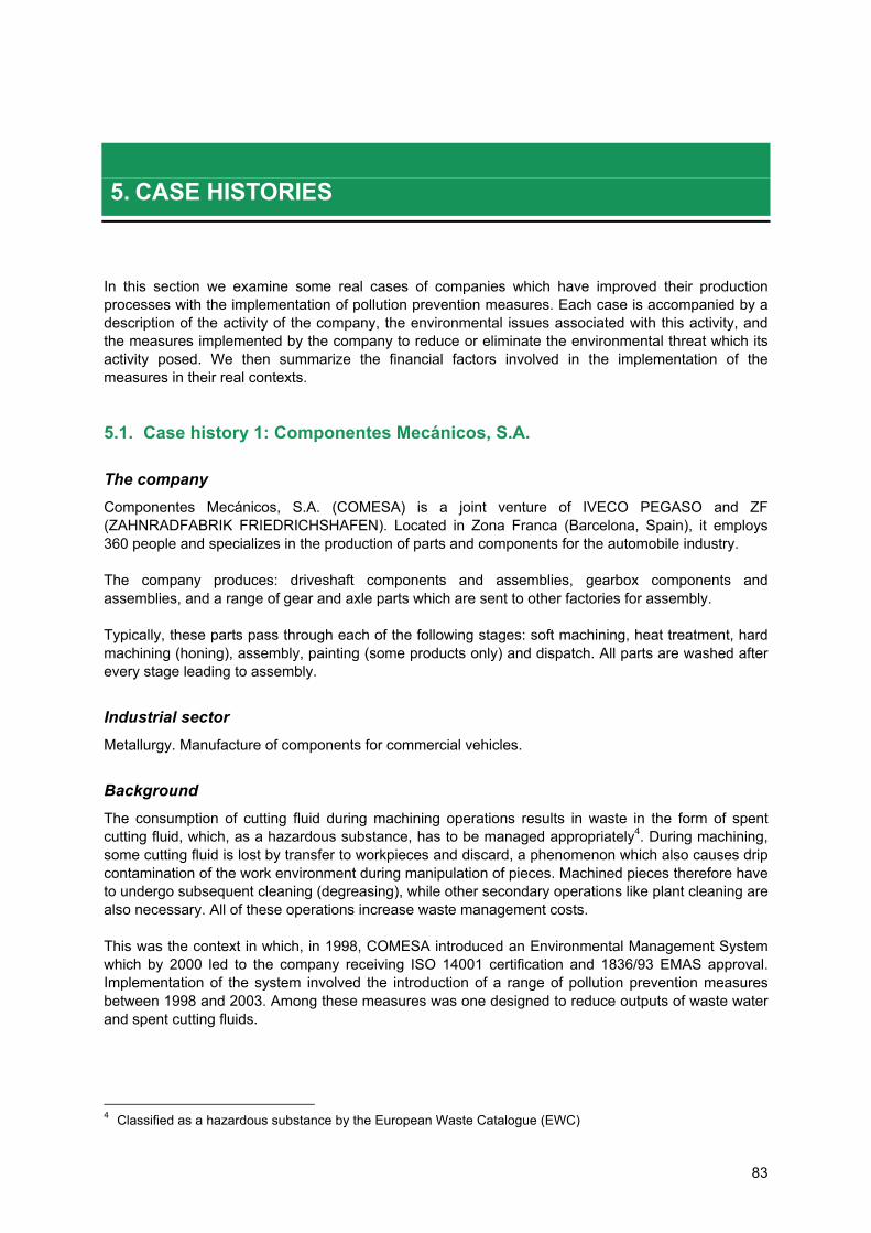
83
5. CASE HISTORIES
In this section we examine some real cases of companies which have improved their production processes with the implementation of pollution prevention measures. Each case is accompanied by a description of the activity of the company, the environmental issues associated with this activity, and the measures implemented by the company to reduce or eliminate the environmental threat which its activity posed. We then summarize the financial factors involved in the implementation of the measures in their real contexts.
5.1. Case history 1: Componentes Mecánicos, S.A.
The company Componentes Mecánicos, S.A. (COMESA) is a joint venture of IVECO PEGASO and ZF (ZAHNRADFABRIK FRIEDRICHSHAFEN). Located in Zona Franca (Barcelona, Spain), it employs 360 people and specializes in the production of parts and components for the automobile industry. The company produces: driveshaft components and assemblies, gearbox components and assemblies, and a range of gear and axle parts which are sent to other factories for assembly. Typically, these parts pass through each of the following stages: soft machining, heat treatment, hard machining (honing), assembly, painting (some products only) and dispatch. All parts are washed after every stage leading to assembly.
Industrial sector Metallurgy. Manufacture of components for commercial vehicles.
Background The consumption of cutting fluid during machining operations results in waste in the form of spent cutting fluid, which, as a hazardous substance, has to be managed appropriately4. During machining, some cutting fluid is lost by transfer to workpieces and discard, a phenomenon which also causes drip contamination of the work environment during manipulation of pieces. Machined pieces therefore have to undergo subsequent cleaning (degreasing), while other secondary operations like plant cleaning are also necessary. All of these operations increase waste management costs. This was the context in which, in 1998, COMESA introduced an Environmental Management System which by 2000 led to the company receiving ISO 14001 certification and 1836/93 EMAS approval. Implementation of the system involved the introduction of a range of pollution prevention measures between 1998 and 2003. Among these measures was one designed to reduce outputs of waste water and spent cutting fluids.
4 Classified as a hazardous substance by the European Waste Catalogue (EWC)
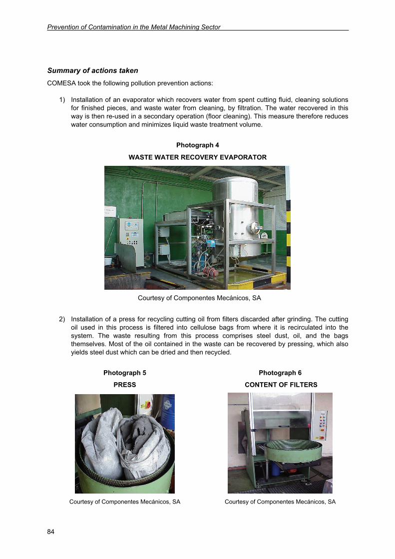
Prevention of Contamination in the Metal Machining Sector
84
Summary of actions taken COMESA took the following pollution prevention actions:
1) Installation of an evaporator which recovers water from spent cutting fluid, cleaning solutions for finished pieces, and waste water from cleaning, by filtration. The water recovered in this way is then re-used in a secondary operation (floor cleaning). This measure therefore reduces water consumption and minimizes liquid waste treatment volume.
Photograph 4
WASTE WATER RECOVERY EVAPORATOR
Courtesy of Componentes Mecánicos, SA
2) Installation of a press for recycling cutting oil from filters discarded after grinding. The cutting
oil used in this process is filtered into cellulose bags from where it is recirculated into the system. The waste resulting from this process comprises steel dust, oil, and the bags themselves. Most of the oil contained in the waste can be recovered by pressing, which also yields steel dust which can be dried and then recycled.
Photograph 5 Photograph 6
PRESS CONTENT OF FILTERS
Courtesy of Componentes Mecánicos, SA Courtesy of Componentes Mecánicos, SA
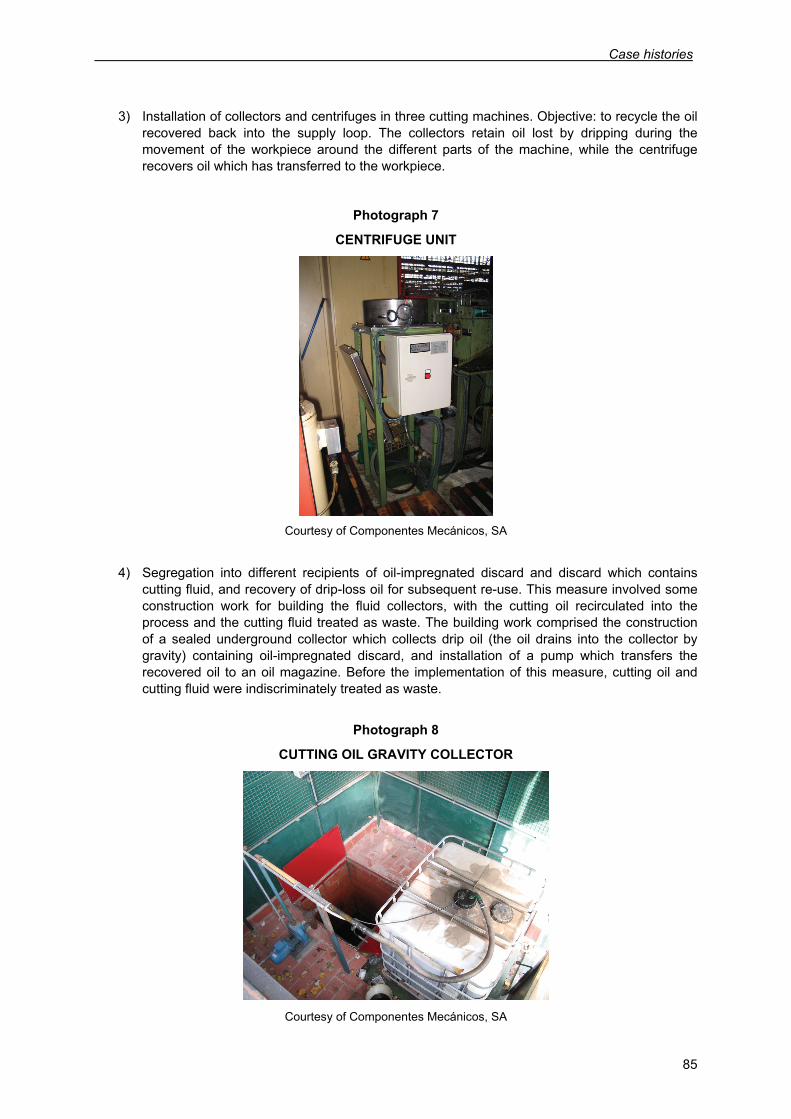
Case histories
85
3) Installation of collectors and centrifuges in three cutting machines. Objective: to recycle the oil recovered back into the supply loop. The collectors retain oil lost by dripping during the movement of the workpiece around the different parts of the machine, while the centrifuge recovers oil which has transferred to the workpiece.
Photograph 7
CENTRIFUGE UNIT
Courtesy of Componentes Mecánicos, SA
4) Segregation into different recipients of oil-impregnated discard and discard which contains
cutting fluid, and recovery of drip-loss oil for subsequent re-use. This measure involved some construction work for building the fluid collectors, with the cutting oil recirculated into the process and the cutting fluid treated as waste. The building work comprised the construction of a sealed underground collector which collects drip oil (the oil drains into the collector by gravity) containing oil-impregnated discard, and installation of a pump which transfers the recovered oil to an oil magazine. Before the implementation of this measure, cutting oil and cutting fluid were indiscriminately treated as waste.
Photograph 8
CUTTING OIL GRAVITY COLLECTOR
Courtesy of Componentes Mecánicos, SA
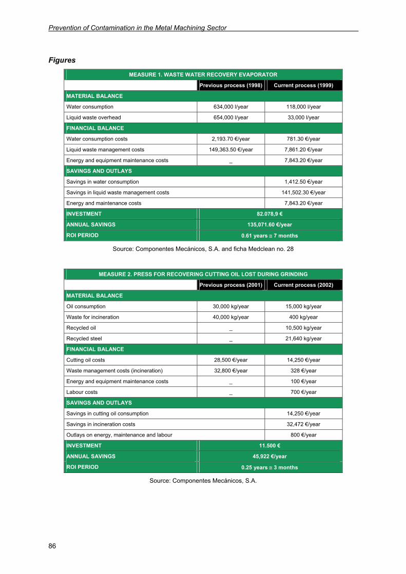
Prevention of Contamination in the Metal Machining Sector
86
Figures
MEASURE 1. WASTE WATER RECOVERY EVAPORATOR
Previous process (1998) Current process (1999)
MATERIAL BALANCE
Water consumption 634,000 l/year 118,000 l/year
Liquid waste overhead 654,000 l/year 33,000 l/year
FINANCIAL BALANCE
Water consumption costs 2,193.70 €/year 781.30 €/year
Liquid waste management costs 149,363.50 €/year 7,861.20 €/year
Energy and equipment maintenance costs _ 7,843.20 €/year
SAVINGS AND OUTLAYS
Savings in water consumption 1,412.50 €/year
Savings in liquid waste management costs 141,502.30 €/year
Energy and maintenance costs 7,843.20 €/year
INVESTMENT 82.078,9 €
ANNUAL SAVINGS 135,071.60 €/year
ROI PERIOD 0.61 years ≅ 7 months
Source: Componentes Mecánicos, S.A. and ficha Medclean no. 28
MEASURE 2. PRESS FOR RECOVERING CUTTING OIL LOST DURING GRINDING
Previous process (2001) Current process (2002)
MATERIAL BALANCE
Oil consumption 30,000 kg/year 15,000 kg/year
Waste for incineration 40,000 kg/year 400 kg/year
Recycled oil _ 10,500 kg/year
Recycled steel _ 21,640 kg/year
FINANCIAL BALANCE
Cutting oil costs 28,500 €/year 14,250 €/year
Waste management costs (incineration) 32,800 €/year 328 €/year
Energy and equipment maintenance costs _ 100 €/year
Labour costs _ 700 €/year
SAVINGS AND OUTLAYS
Savings in cutting oil consumption 14,250 €/year
Savings in incineration costs 32,472 €/year
Outlays on energy, maintenance and labour 800 €/year
INVESTMENT 11.500 €
ANNUAL SAVINGS 45,922 €/year
ROI PERIOD 0.25 years ≅ 3 months
Source: Componentes Mecánicos, S.A.
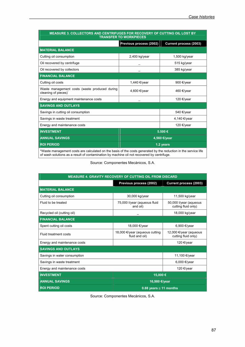
Case histories
87
Source: Componentes Mecánicos, S.A.
MEASURE 4. GRAVITY RECOVERY OF CUTTING OIL FROM DISCARD
Previous process (2002) Current process (2003)
MATERIAL BALANCE
Cutting oil consumption 30,000 kg/year 11,500 kg/year
Fluid to be treated 75,000 l/year (aqueous fluid and oil)
50,000 l/year (aqueous cutting fluid only)
Recycled oil (cutting oil) _ 18,000 kg/year
FINANCIAL BALANCE
Spent cutting oil costs 18,000 €/year 6,900 €/year
Fluid treatment costs 18,000 €/year (aqueous cutting fluid and oil)
12,000 €/year (aqueous cutting fluid only)
Energy and maintenance costs 120 €/year
SAVINGS AND OUTLAYS
Savings in water consumption 11,100 €/year
Savings in waste treatment 6,000 €/year
Energy and maintenance costs 120 €/year
INVESTMENT 15,000 €
ANNUAL SAVINGS 16,980 €/year
ROI PERIOD 0.88 years ≅ 11 months
Source: Componentes Mecánicos, S.A.
MEASURE 3. COLLECTORS AND CENTRIFUGES FOR RECOVERY OF CUTTING OIL LOST BY TRANSFER TO WORKPIECES
Previous process (2002) Current process (2003)
MATERIAL BALANCE
Cutting oil consumption 2,400 kg/year 1,500 kg/year
Oil recovered by centrifuge _ 515 kg/year
Oil recovered by collectors _ 385 kg/year
FINANCIAL BALANCE
Cutting oil costs 1,440 €/year 900 €/year
Waste management costs (waste produced during cleaning of pieces)* 4,600 €/year 460 €/year
Energy and equipment maintenance costs _ 120 €/year
SAVINGS AND OUTLAYS
Savings in cutting oil consumption 540 €/year
Savings in waste treatment 4,140 €/year
Energy and maintenance costs 120 €/year
INVESTMENT 5.500 €
ANNUAL SAVINGS 4,560 €/year
ROI PERIOD 1.2 years
*Waste management costs are calculated on the basis of the costs generated by the reduction in the service life of wash solutions as a result of contamination by machine oil not recovered by centrifuge.
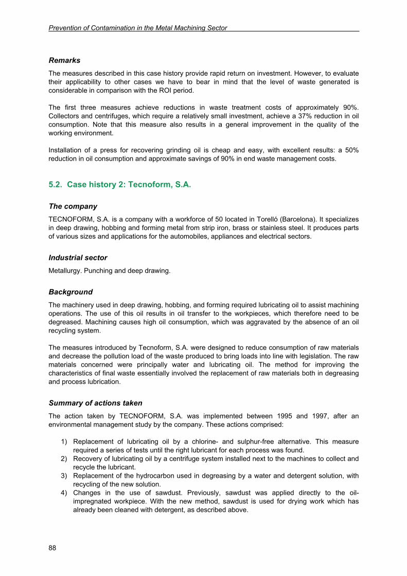
Prevention of Contamination in the Metal Machining Sector
88
Remarks The measures described in this case history provide rapid return on investment. However, to evaluate their applicability to other cases we have to bear in mind that the level of waste generated is considerable in comparison with the ROI period. The first three measures achieve reductions in waste treatment costs of approximately 90%. Collectors and centrifuges, which require a relatively small investment, achieve a 37% reduction in oil consumption. Note that this measure also results in a general improvement in the quality of the working environment. Installation of a press for recovering grinding oil is cheap and easy, with excellent results: a 50% reduction in oil consumption and approximate savings of 90% in end waste management costs.
5.2. Case history 2: Tecnoform, S.A.
The company TECNOFORM, S.A. is a company with a workforce of 50 located in Torelló (Barcelona). It specializes in deep drawing, hobbing and forming metal from strip iron, brass or stainless steel. It produces parts of various sizes and applications for the automobiles, appliances and electrical sectors.
Industrial sector Metallurgy. Punching and deep drawing.
Background The machinery used in deep drawing, hobbing, and forming required lubricating oil to assist machining operations. The use of this oil results in oil transfer to the workpieces, which therefore need to be degreased. Machining causes high oil consumption, which was aggravated by the absence of an oil recycling system. The measures introduced by Tecnoform, S.A. were designed to reduce consumption of raw materials and decrease the pollution load of the waste produced to bring loads into line with legislation. The raw materials concerned were principally water and lubricating oil. The method for improving the characteristics of final waste essentially involved the replacement of raw materials both in degreasing and process lubrication.
Summary of actions taken The action taken by TECNOFORM, S.A. was implemented between 1995 and 1997, after an environmental management study by the company. These actions comprised:
1) Replacement of lubricating oil by a chlorine- and sulphur-free alternative. This measure required a series of tests until the right lubricant for each process was found.
2) Recovery of lubricating oil by a centrifuge system installed next to the machines to collect and recycle the lubricant.
3) Replacement of the hydrocarbon used in degreasing by a water and detergent solution, with recycling of the new solution.
4) Changes in the use of sawdust. Previously, sawdust was applied directly to the oil-impregnated workpiece. With the new method, sawdust is used for drying work which has already been cleaned with detergent, as described above.
Case histories
89
5) Enforcement of a best-practice policy among personnel designed to reduce frequency of floor cleaning and eliminate the use of acid detergents.
Figures
Before improvements After improvements
CONSUMPTION Lubricating oil 5,000 l/year 2,500 l/year
Water for cleaning parts 2,600 m3/year 700 m3/year
Hydrocarbons for degreasing 1,400 kg/year 0
Detergents for degreasing 3,300 kg/year 1,050 kg/year
Sawdust 14 t/year 3 t/year
FINANCIAL BALANCE Lubricating oil 18,816 €/year 11,961 €/year
Water for cleaning parts 906 €/year 244 €/year
Hydrocarbons for degreasing 1,240 €/year 0 €/year
Detergents for degreasing 5,975 €/year 2,690 €/year
Sawdust 5.47 €/year 1,623 €/year
Waste management 1,985 €/year 2,855 €/year
Treatment of waste water 193 €/year 3,306 €/year
SAVINGS AND OUTLAYS Savings in lubricating oil 6,855 €/year
Water savings 662 €/year
Savings in degreasing agents 7,949 €/year
Increased waste and waste water management costs 3,983 €/year
INVESTMENT 31. 444 € ANNUAL SAVINGS 11,483 €/year ROI PERIOD 2.7 years
Source: File P+N no. 14
Remarks Since 1995 the company’s progressive renovation of its operating methods has achieved reductions in consumption and in the environmental hazards posed by the waste it produces. Consumption of lubrication oil has fallen by 50% and of sawdust by approximately 75%; and hydrocarbon consumption for degreasing operations has been totally eliminated. At the same time, a small gain in productivity has been obtained due to the reduction in cleaning times and more efficient degreasing.
5.3. Case history 3: Grupo Elcoro Decoletaje, S.L.
The company GRUPO ELCORO DECOLETAJE, S.L. was founded in 1892 and currently has 3 production plants, two in Elgeta y Mendaro (Guipúzcoa, Spain) and a third in Pamplona (Navarra, Spain). The company employs around 150 people. It specializes in the manufacture of machined parts for a variety of sectors, including: automobile, eolian, electrical, tools, and others.
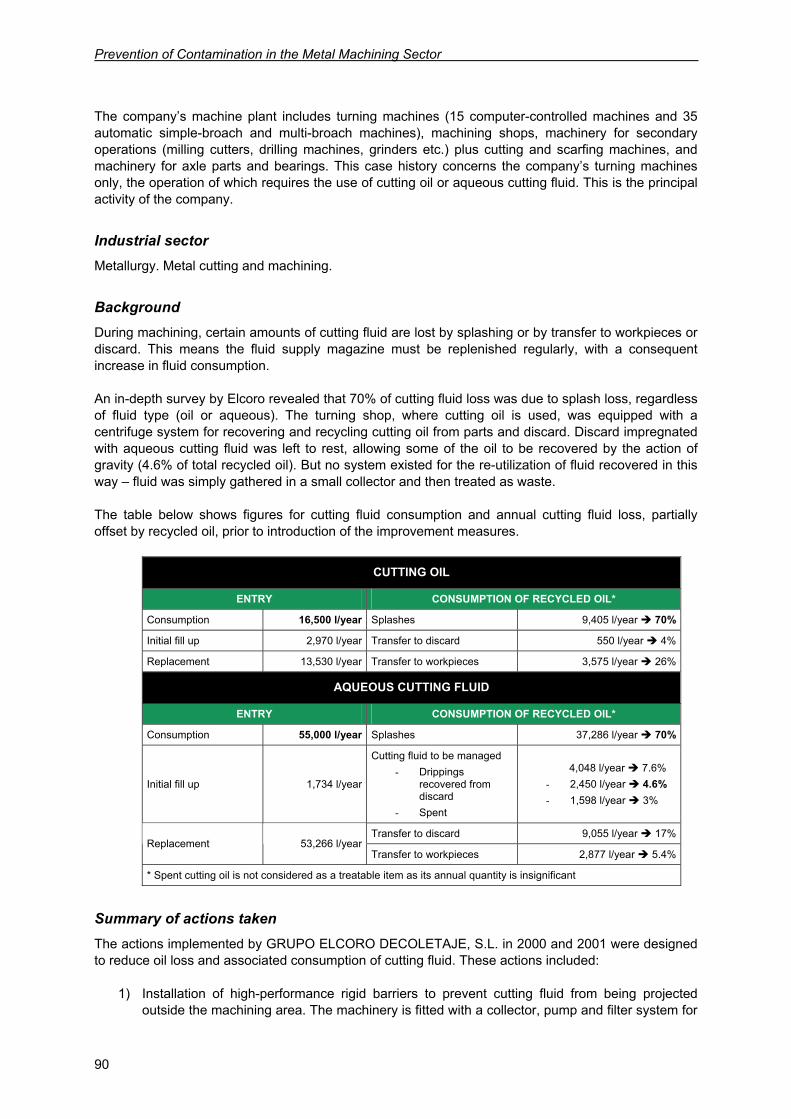
Prevention of Contamination in the Metal Machining Sector
90
The company’s machine plant includes turning machines (15 computer-controlled machines and 35 automatic simple-broach and multi-broach machines), machining shops, machinery for secondary operations (milling cutters, drilling machines, grinders etc.) plus cutting and scarfing machines, and machinery for axle parts and bearings. This case history concerns the company’s turning machines only, the operation of which requires the use of cutting oil or aqueous cutting fluid. This is the principal activity of the company.
Industrial sector Metallurgy. Metal cutting and machining.
Background During machining, certain amounts of cutting fluid are lost by splashing or by transfer to workpieces or discard. This means the fluid supply magazine must be replenished regularly, with a consequent increase in fluid consumption. An in-depth survey by Elcoro revealed that 70% of cutting fluid loss was due to splash loss, regardless of fluid type (oil or aqueous). The turning shop, where cutting oil is used, was equipped with a centrifuge system for recovering and recycling cutting oil from parts and discard. Discard impregnated with aqueous cutting fluid was left to rest, allowing some of the oil to be recovered by the action of gravity (4.6% of total recycled oil). But no system existed for the re-utilization of fluid recovered in this way – fluid was simply gathered in a small collector and then treated as waste. The table below shows figures for cutting fluid consumption and annual cutting fluid loss, partially offset by recycled oil, prior to introduction of the improvement measures.
CUTTING OIL
ENTRY CONSUMPTION OF RECYCLED OIL*
Consumption 16,500 l/year Splashes 9,405 l/year 70%
Initial fill up 2,970 l/year Transfer to discard 550 l/year 4%
Replacement 13,530 l/year Transfer to workpieces 3,575 l/year 26%
AQUEOUS CUTTING FLUID
ENTRY CONSUMPTION OF RECYCLED OIL*
Consumption 55,000 l/year Splashes 37,286 l/year 70%
Initial fill up 1,734 l/year
Cutting fluid to be managed - Drippings
recovered from discard
- Spent
4,048 l/year 7.6% - 2,450 l/year 4.6% - 1,598 l/year 3%
Transfer to discard 9,055 l/year 17%Replacement 53,266 l/year
Transfer to workpieces 2,877 l/year 5.4%
* Spent cutting oil is not considered as a treatable item as its annual quantity is insignificant
Summary of actions taken The actions implemented by GRUPO ELCORO DECOLETAJE, S.L. in 2000 and 2001 were designed to reduce oil loss and associated consumption of cutting fluid. These actions included:
1) Installation of high-performance rigid barriers to prevent cutting fluid from being projected outside the machining area. The machinery is fitted with a collector, pump and filter system for
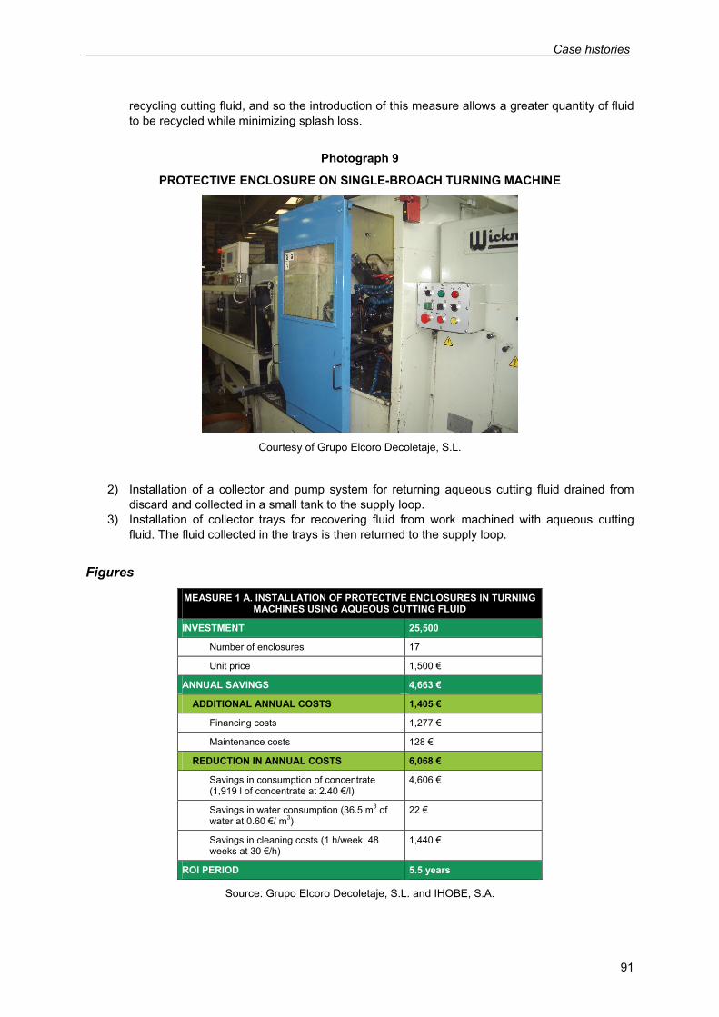
Case histories
91
recycling cutting fluid, and so the introduction of this measure allows a greater quantity of fluid to be recycled while minimizing splash loss.
Photograph 9
PROTECTIVE ENCLOSURE ON SINGLE-BROACH TURNING MACHINE
Courtesy of Grupo Elcoro Decoletaje, S.L.
2) Installation of a collector and pump system for returning aqueous cutting fluid drained from discard and collected in a small tank to the supply loop.
3) Installation of collector trays for recovering fluid from work machined with aqueous cutting fluid. The fluid collected in the trays is then returned to the supply loop.
Figures
MEASURE 1 A. INSTALLATION OF PROTECTIVE ENCLOSURES IN TURNING MACHINES USING AQUEOUS CUTTING FLUID
INVESTMENT 25,500
Number of enclosures 17
Unit price 1,500 €
ANNUAL SAVINGS 4,663 €
ADDITIONAL ANNUAL COSTS 1,405 €
Financing costs 1,277 €
Maintenance costs 128 €
REDUCTION IN ANNUAL COSTS 6,068 €
Savings in consumption of concentrate (1,919 l of concentrate at 2.40 €/l)
4,606 €
Savings in water consumption (36.5 m3 of water at 0.60 €/ m3)
22 €
Savings in cleaning costs (1 h/week; 48 weeks at 30 €/h)
1,440 €
ROI PERIOD 5.5 years
Source: Grupo Elcoro Decoletaje, S.L. and IHOBE, S.A.
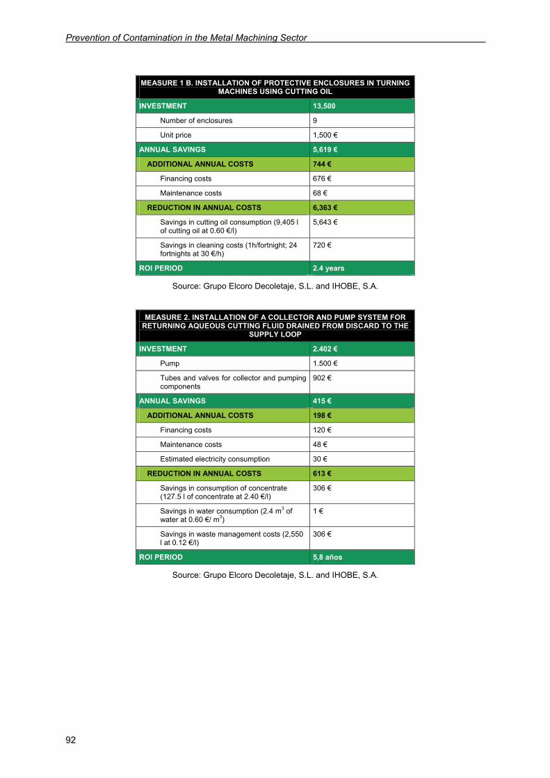
Prevention of Contamination in the Metal Machining Sector
92
MEASURE 1 B. INSTALLATION OF PROTECTIVE ENCLOSURES IN TURNING MACHINES USING CUTTING OIL
INVESTMENT 13,500
Number of enclosures 9
Unit price 1,500 €
ANNUAL SAVINGS 5,619 €
ADDITIONAL ANNUAL COSTS 744 €
Financing costs 676 €
Maintenance costs 68 €
REDUCTION IN ANNUAL COSTS 6,363 €
Savings in cutting oil consumption (9,405 l of cutting oil at 0.60 €/l)
5,643 €
Savings in cleaning costs (1h/fortnight; 24 fortnights at 30 €/h)
720 €
ROI PERIOD 2.4 years
Source: Grupo Elcoro Decoletaje, S.L. and IHOBE, S.A.
MEASURE 2. INSTALLATION OF A COLLECTOR AND PUMP SYSTEM FOR
RETURNING AQUEOUS CUTTING FLUID DRAINED FROM DISCARD TO THE SUPPLY LOOP
INVESTMENT 2.402 €
Pump 1.500 €
Tubes and valves for collector and pumping components
902 €
ANNUAL SAVINGS 415 €
ADDITIONAL ANNUAL COSTS 198 €
Financing costs 120 €
Maintenance costs 48 €
Estimated electricity consumption 30 €
REDUCTION IN ANNUAL COSTS 613 €
Savings in consumption of concentrate (127.5 l of concentrate at 2.40 €/l)
306 €
Savings in water consumption (2.4 m3 of water at 0.60 €/ m3)
1 €
Savings in waste management costs (2,550 l at 0.12 €/l)
306 €
ROI PERIOD 5,8 años
Source: Grupo Elcoro Decoletaje, S.L. and IHOBE, S.A.
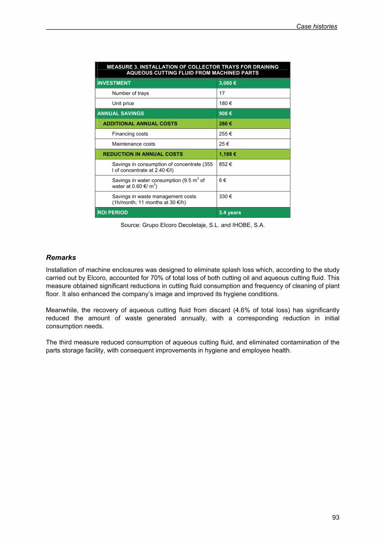
Case histories
93
MEASURE 3. INSTALLATION OF COLLECTOR TRAYS FOR DRAINING
AQUEOUS CUTTING FLUID FROM MACHINED PARTS
INVESTMENT 3,060 €
Number of trays 17
Unit price 180 €
ANNUAL SAVINGS 908 €
ADDITIONAL ANNUAL COSTS 280 €
Financing costs 255 €
Maintenance costs 25 €
REDUCTION IN ANNUAL COSTS 1,188 €
Savings in consumption of concentrate (355 l of concentrate at 2.40 €/l)
852 €
Savings in water consumption (9.5 m3 of water at 0.60 €/ m3)
6 €
Savings in waste management costs (1h/month; 11 months at 30 €/h)
330 €
ROI PERIOD 3.4 years
Source: Grupo Elcoro Decoletaje, S.L. and IHOBE, S.A.
Remarks Installation of machine enclosures was designed to eliminate splash loss which, according to the study carried out by Elcoro, accounted for 70% of total loss of both cutting oil and aqueous cutting fluid. This measure obtained significant reductions in cutting fluid consumption and frequency of cleaning of plant floor. It also enhanced the company’s image and improved its hygiene conditions. Meanwhile, the recovery of aqueous cutting fluid from discard (4.6% of total loss) has significantly reduced the amount of waste generated annually, with a corresponding reduction in initial consumption needs. The third measure reduced consumption of aqueous cutting fluid, and eliminated contamination of the parts storage facility, with consequent improvements in hygiene and employee health.

95
6. CONCLUSIONS
The use of cutting fluids is one of the most characteristic features of the metal machining sector, and also one of the major environmental issues which this sector raises. As it loses its initial properties, cutting fluid becomes waste5 which has to be correctly managed if its harmful effects on the environment are to be minimized. Cutting fluid use can occasionally cause the formation of oil mists during processes, as well as drip and splash contamination of the working environment. Some cutting fluid is lost through transfer to work and to discard, which means finished parts have to be degreased. This in turn means that the composition of the degreasing agent determines how problematic disposal of the resulting waste is going to be. Given the environmental threat posed by the use of cutting fluid, many opportunities for integrated pollution prevention involve reducing the production of this waste, and recycling what waste is produced. Pollution reduction at source is an area offering alternatives either for the replacement of traditional cutting fluids by others whose composition is more environmentally friendly, or for reduction in consumption (dry machining, MQL technology, machine enclosures, control and maintenance of cutting fluid and optimization of application conditions) and the formation of oil mists in the working environment. Recovery and recycling at source includes aspects such as maintenance of cutting oil (using equipment which separates solids and other impurities found in spent fluid), degreasing solutions, and other liquid waste (evaporation, distillation, flotation, adsorption, electrolytic separation and ultrafiltration). Good housekeeping practices are another area of importance. These practices are cheap and easy to implement, with rapid and often surprising results. It’s evident therefore that a great variety of solutions is available to the metal machining sector. The costs of these solutions, whether designed to economize on cutting oil consumption or to reduce waste, can also vary greatly. Given the range of alternatives on offer, and the costs and applicability conditions associated with each one, the recommended course of action is to conduct a feasibility study designed to determine which environmental improvement measures are best suited to each specific case. The importance of a feasibility study becomes clearer still if we consider the context addressed by this manual and the heterogeneity of the countries which are signatories to the MAP. This heterogeneity exists with regard to the situation and characteristics of the different industrials sectors, to the resources mobilized for the adoption of cleaner production measures by companies, and to differences in environmental legislation in signatory states.
5 Classified as a hazardous substance by the European Waste Catalogue (EWC)


97
7. BIBLIOGRAPHY
7.1. Studies
GENERALITAT DE CATALUNYA. DEPARTAMENT DE MEDI AMBIENT. CENTRE PER A L’EMPRESA I EL MEDI AMBIENT, S.A. Estudi sectorial de minimització del sector metal·lúrgic ubicat o proper a zones urbanes. June 2002. (Unpublished)
GENERALITAT DE CATALUNYA. DEPARTAMENT DE MEDI AMBIENT. CENTRE PER A
L’EMPRESA I EL MEDI AMBIENT, S.A. Sector metal·lúrgic: Base de dades de tecnologies. October 2000. (Unpublished)
GENERALITAT DE CATALUNYA. DEPARTAMENT DE MEDI AMBIENT. CENTRE PER A
L’EMPRESA I EL MEDI AMBIENT, S.A. Grup de treball al sector metal·lúrgic. April 2001. (Unpublished)
EUROPEAN COMISSION. DIRECTORATE-GENERAL JRC (JOINT RESEARCH CENTRE). Institute
for Prospective Technological Studies. Technologies for Sustainable Development. European IPPC Bureau. Integrated Pollution Prevention and Control (IPPC). Reference Document on Best Available Techniques in the Ferrous Metals Processing Industry. December 2001. (Available online at http://www.gencat.es)
EUROPEAN COMISSION. DIRECTORATE-GENERAL JRC (JOINT RESEARCH CENTRE). Institute
for Prospective Technological Studies. Technologies for Sustainable Development. European IPPC Bureau. Integrated Pollution Prevention and Control (IPPC). Source: Reference Document on Best Available Techniques in the Non Ferrous Industries. December 2001. (Available online at http://www.gencat.es)
ENVIRONMENTAL PROTECTION AGENCY (EPA). US EPA Office of Compliance Sector Notebook
Project - Profile of the Fabricated Metal Products Industry. September 1995. (Available online at http://www.epa.org)
U.S. EPA/SEDESOL (Pollution Prevention Workgroup). La minimización de residuos en la industria
del acabado de metales. May 1993. (Available online at http://www.epa.org) A. GARCÍA. El sector industrial metalúrgico en España y Cataluña. Ed.: Maquitec 2002 – Fira de
Barcelona. September 2002. (Available online at http://www.maquitec.com) REGIONAL ACTIVITY CENTRE FOR CLEANER PRODUCTION (RAC/CP). State of Cleaner
Production in the Mediterranean Action Plan Countries. June 2001. (Available online at http://www.gencat.es)
REGIONAL ACTIVITY CENTRE FOR CLEANER PRODUCTION (RAC/CP). State of Cleaner
Production in the Mediterranean Action Plan Countries. 2nd edition. January 2004. REGIONAL ACTIVITY CENTRE FOR CLEANER PRODUCTION (RAC/CP). Status and Trends of
Industry and Sustainable Development in the Mediterranean Region. October 2001. (Available online at http://www.gencat.es)
Prevention of Contamination in the Metal Machining Sector
98
7.2. Publications
GENERALITAT DE CATALUNYA. DEPARTAMENT DE MEDI AMBIENT. Manuals d’ecogestió nº 6. Prevenció de la contaminació al sector de tractament de superfícies. February 2002.
GENERALITAT DE CATALUNYA. DEPARTAMENT DE MEDI AMBIENT. Seminaris territorials sobre
qualificació ambiental a les empreses. Fitxa 10: La qualitat ambiental al sector del metall. GENERALITAT DE CATALUNYA. DEPARTAMENT D’INDÚSTRIA I ENERGIA. Indústria bàsica i
productes metàl·lics. La indústria a Catalunya, núm. 5. 1991 GENERALITAT DE CATALUNYA. DEPARTAMENT DE MEDI AMBIENT. CENTRE PER A
L’EMPRESA I EL MEDI AMBIENT. Col·lecció Fitxes P+N. (Available online at http://www.cema-sa.org)
GENERALITAT DE CATALUNYA. DEPARTAMENT DE MEDI AMBIENT. CENTRE D’ACTIVITATS
REGIONALS PER A LA PRODUCCIÓ NETA (CAR-PN). Fichas Medclean. (Available online at http://www.gencat.es)
GENERALITAT DE CATALUNYA. DEPARTAMENT DE TREBALL, INDÚSTRIA, COMERÇ I
TURISME. Informe anual sobre la indústria a Catalunya, 2002. July 2001. (Available online at http://www.gencat.es)
IHOBE, S.A. Libro blanco para la minimización de residuos y emisiones. Mecanizado del metal. 1999.
(Available online at http://www.ihobe.es) IHOBE, S.A. Taladrinas agotadas: Un residuo a reducir. 1993 (republished 1997). (Available online at
http://www.ihobe.es) IHOBE, S.A. Reducción de costes mediante una gestión eficaz de las virutas. 2002. (Available online
at http://www.ihobe.es) IHOBE, S.A. Listado vasco de tecnologías limpias. 2004. (Available online at http://www.ihobe.es) IHOBE, S.A. Excelencia ambiental en empresas vascas: Casos prácticos. 2004. (Available online at
http://www.ihobe.es) CONFEDERACIÓN DE LA PEQUEÑA Y MEDIANA EMPRESA ARAGONESA (CEPYME/ARAGÓN).
Manual de minimización de residuos y emisiones industriales para las industrias transformadoras de los metales del sector metal. (Unpublished)
CESI COFOR, S.A. Guía de gestión medioambiental para empresas del sector del metal de la
provincia de Badajoz. Consejería de Economía y Trabajo de la Junta de Extremadura. March 2004.
GENERALITAT VALENCIANA. CONSELLERIA DE MEDI AMBIENT. Las buenas prácticas
medioambientales en metalmecánica. Conselleria de Medi Ambient de la Generalitat Valenciana y Consejo de Cámaras de la Comunidad Valenciana. 2000.
INSTITUTO NACIONAL DE ESTADÍSTICA (INE). Anuario Estadístico de España. 2004. (Available
online at http://www.ine.es)
Bibliography
99
7.3. Technical literature
Filtration News, no. 8. Published by Kenfilt-Novotecnic. September 2004 Service Lub (a periodical published by Europe’s leading lubricants group). October-November 2004
7.4. Books
J. VIVANCOS et al. Tecnologías de Fabricación. Tomo I. Procesos de mecanizado. ETS d’Enginyeria Industrial de Barcelona. 1996 A. NÁPOLES et al. Tecnología mecánica. Ediciones UPC. 2002 P. MOLERA. Conformación metálica. Ed. Marcombo. 1991 J. VIVANCOS et al. Tecnologías de Fabricación. Tomo II. Procesos de Fusión, moldeo y deformación. ETS d’Enginyeria Industrial de Barcelona. 1998 A. LEYENSETTER. Tecnología de los oficios metalúrgicos. Editorial Reverté, S.A. 1987 J. E. NEELY. Metalurgia y materiales industriales. Ed. Limusa, S.A. 2001 F. R. MORRAL et al. Metalurgia general. Tomo II. Ed. Reverté, S.A. 1985 TUBAL CAIN. Endurecimiento, revenido y tratamiento térmico. Ed. G. Gili, S.A. 1993 J. M. LASHERAS. Tecnología mecánica y metrotécnia. Ed. Donostiarra, S.A. 1997.
7.5. Websites
http://www.gencat.es/mediamb (Ministry of the Environment of the Government of Catalonia)
http://www.cema-sa.org (Centre for the Enterprise and the Environment, SA)
http://www.mma.es (Spanish Ministry of the Environment)
http://www.eper-es.com (Spanish State Register for Emissions and Sources of Pollution, Reporting to the Spanish Ministry of the Environment)
http://www.mtas.es (Spanish Ministry of Employment and Social affairs)
http://www.ihobe.es (IHOBE, Environmental Management Company)
http://www.fundacionentorno.org (Entorno Foundation)
http://www.eippcb.jrc.es (European Integrated Pollution Prevention Control Bureau)
http://www.epa.org (Environmental Protection Agency)
http://www.ceam-metal.es (Study And Consulting Centre for Metallurgy)
http://www.confemetal.es (Spanish Confederation of Business Organizations in the Metals Sector)
http://www.aimme.es (Institute of Metal Machining and Technology)
http://cepymearagon.es (Aragonese Confederation of Small and Medium Businesses)
http://www.istas.net (Autonomous Foundation of National Workers’ Syndicate, Comisiones Obreras)
http://www.unepmap.gr (United Nations Environment Programme Mediterranean Action Plan)
Prevention of Contamination in the Metal Machining Sector
100
http://www.unido.org (United Nations Industrial Development Organization)
http://www.ine.es (Spanish National Statistics Institute)
http://www.instat.gov.al (Institute of Statistics of Albania)
http://www.ons.dz (Statistics Algeria. National Office of Statistics)
http://www.bhas.ba (Agency for Statistics of Bosnia and Herzegovina)
http://www.dzs.hr (Republic of Croatia-Central Bureau of Statistics)
http://www.capmas.gov.eg (Central Agency for Public Mobilization and Statistics)
http://www.stat.si (Statistical Office of the Republic of Slovenia)
http://www.ine.es (Spanish National Statistics Institute)
http://www.insee.fr (Institut National de la Statistique et des Etudes)
http://www.statistics.gr (General Secretariat of National Statistical Service of Greece)
http://www.cbs.gov.il (Central Bureau of Statistic of Israel)
http://www.istat.it (National Institute of Statistics Italia)
http://www.cas.gov.lb (Central Administration for Statistics. Lebanese Republic)
http://www.szs.sv.gov.yu (Serbia and Montenegro Statistical Office)
http://www.tunisianindustry.nat.tn (Tunisian Industry Portal)
http://www.die.gov.tr (State Institute of Statistics Turkey)
7.6. Companies in the metal machining sector
Componentes Mecánicos, S.A. (COMESA): http://www.comesa.es
Cotecing, S.L.
Dilube, S.A. Grupo Olivé: http://www.dilube.com
Filter 2000, S.L.: www.filter-2000.com
Chimiderouil, S.A.: http://www.chimiderouil.com
Industrias Metalúrgicas JEM, S.A.: http://www.jem.es
Gamor, S.L.: http://www.gamor.es
Tecnoform, S.A.
Grupo Elcoro Decoletaje, S.L.: http://www.elcoro.com
Canaletas, S.A.: http://www.canaletas.es
Barin, S.A.: www.barin.es
Novotecnic Europa, S.A.: www.kenfilt.net
Metales y Formas, S.L.
101
8. ACKNOWLEDGEMENTS
We would like to extend our sincerest thanks to Mr Robert Gilart of Componentes Mecánicos, S.A. for the selfless dedication he showed in his revision of sections 3 and 4 of this manual. We also thank Mr José Pedro Díaz Barrera of Cotecing, S.L., Mrs Mónica Folch and Mr Miquel Comas of Dilube, S.A. (Grupo Olivé), Mr Fritz Schmid of Filter 2000, S.L. and Mr Josep Maria Torras of Chimiderouil, S.A. for sharing their expertise with us during our preparation of the manual. We are also grateful for the co-operation of Grupo Elcoro Decoletaje, S.L., Componentes Metálicos, S.A. and Tecnoform, S.A., who kindly provided us with information for the case histories section, and of Talleres Gamor, S.L. and Canaletas, S.A. for providing us with photographs illustrating some of the processes discussed in this manual. To all of the above we are greatly obliged.

103
9. ANNEX. IMPORTANCE OF THE METALLURGY SECTOR
IN MAP COUNTRIES
The metallurgy sector accounts for an estimated 7% of total industrial output across all countries in which the Mediterranean Action Plan (MAP) is applied6. In this annex we examine the importance of the metallurgy sector in each member country based on a series of socio-economic indicators. MAP member countries are: Southern Mediterranean countries:
- Algeria - Egypt - Lebanon - Libya - Morocco - Syria - Tunisia
Northern Mediterranean countries: - Spain - France - Greece - Italy - Monaco
Eastern Mediterranean countries: - Albania - Bosnia-Herzegovina - Cyprus - Croatia - Slovenia - Israel - Malta - Serbia and Montenegro - Turkey
In view of the social, political and economic diversity of the 21 member countries, indicators on the metallurgy sector in each particular country are preceded by some general data designed to present each country in a clearer context.
6 RAC/CP A report on Cleaner Production in Mediterranean Action Plan countries. January 2004.
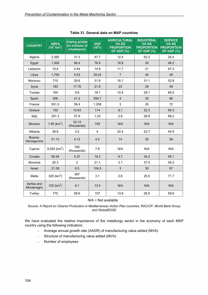
Prevention of Contamination in the Metal Machining Sector
104
Table 31. General data on MAP countries
COUNTRY AREA (103 km2)
POPULATION (in millions of inhabitants)
GDP (109€)
AGRICULTURAL VA AS
PROPORTION OF GDP (%)
INDUSTRIAL VA AS
PROPORTION OF GDP (%)
SERVICE VA AS
PROPORTION OF GDP (%)
Algeria 2,382 31.3 47.7 12.4 62.2 25.4
Egypt 1,000 66.4 76.9 16.8 35 48.2
Lebanon 10,4 4.44 14.8 11.7 21 67.3
Libya 1,759 5.53 29.24 7 44 49
Morocco 710 29.6 31.9 16.1 31.1 52.8
Syria 185 17.76 21.9 23 28 49
Tunisia 164 9.8 18.1 10.4 29.1 60.5
Spain 506 41.2 556.7 4 30 66
France 551.5 59.4 1.208 3 26 72
Greece 132 10.63 114 8,1 22.3 69.3
Italy 301.3 57.9 1.23 2.8 28.9 68.2
Monaco 1.95 (km2) 32.13 (thousands) 745 N/A N/A N/A
Albania 28.8 3.2 4 32.4 22.7 44.9
Bosnia-Herzegovina 51.13 4.12 4.5 14 30 56
Cyprus 9,250 (km2) 765 (thousands) 7.8 N/A N/A N/A
Croatia 56.54 4.37 19.2 9.7 34.2 56.1
Slovenia 20.3 2 21.1 3.1 37.5 59.3
Israel 21.06 6.5 104.5 3 30 67
Malta 320 (km2) 397 (thousands) 3.1 2.8 25.5 71.7
Serbia and Montenegro 102 (km2) 8.1 13.4 N/A N/A N/A
Turkey 775 69.6 157 13.8 26.6 59.6
N/A = Not available Source: A Report on Cleaner Production in Mediterranean Action Plan countries, RAC/CP; World Bank Group
and GlobalEDGE
We have evaluated the relative importance of the metallurgy sector in the economy of each MAP country using the following indicators:
- Average annual growth rate (AAGR) of manufacturing value added (MVA) - Structure of manufacturing value added (MVA) - Number of employees
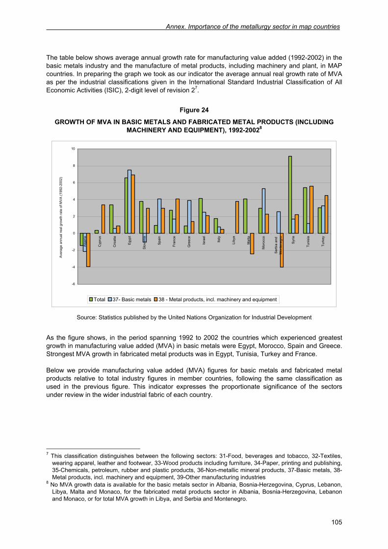
Annex. Importance of the metallurgy sector in map countries
105
The table below shows average annual growth rate for manufacturing value added (1992-2002) in the basic metals industry and the manufacture of metal products, including machinery and plant, in MAP countries. In preparing the graph we took as our indicator the average annual real growth rate of MVA as per the industrial classifications given in the International Standard Industrial Classification of All Economic Activities (ISIC), 2-digit level of revision 27.
Figure 24
GROWTH OF MVA IN BASIC METALS AND FABRICATED METAL PRODUCTS (INCLUDING MACHINERY AND EQUIPMENT), 1992-20028
-6
-4
-2
0
2
4
6
8
10
Alg
eria
Cyp
rus
Cro
atia
Egy
pt
Slo
veni
a
Spa
in
Fran
ce
Gre
ece
Isra
el
Italy
Liby
a
Mal
ta
Mor
occo
Ser
bia
and
Mon
tene
gro
Syr
ia
Tuni
sia
Turk
ey
Ave
rage
ann
ual r
eal g
row
th ra
te o
f MV
A (1
992-
2002
)
Total 37- Basic metals 38 - Metal products, incl. machinery and equipment
Source: Statistics published by the United Nations Organization for Industrial Development
As the figure shows, in the period spanning 1992 to 2002 the countries which experienced greatest growth in manufacturing value added (MVA) in basic metals were Egypt, Morocco, Spain and Greece. Strongest MVA growth in fabricated metal products was in Egypt, Tunisia, Turkey and France. Below we provide manufacturing value added (MVA) figures for basic metals and fabricated metal products relative to total industry figures in member countries, following the same classification as used in the previous figure. This indicator expresses the proportionate significance of the sectors under review in the wider industrial fabric of each country.
7 This classification distinguishes between the following sectors: 31-Food, beverages and tobacco, 32-Textiles,
wearing apparel, leather and footwear, 33-Wood products including furniture, 34-Paper, printing and publishing, 35-Chemicals, petroleum, rubber and plastic products, 36-Non-metallic mineral products, 37-Basic metals, 38-Metal products, incl. machinery and equipment, 39-Other manufacturing industries
8 No MVA growth data is available for the basic metals sector in Albania, Bosnia-Herzegovina, Cyprus, Lebanon, Libya, Malta and Monaco, for the fabricated metal products sector in Albania, Bosnia-Herzegovina, Lebanon and Monaco, or for total MVA growth in Libya, and Serbia and Montenegro.
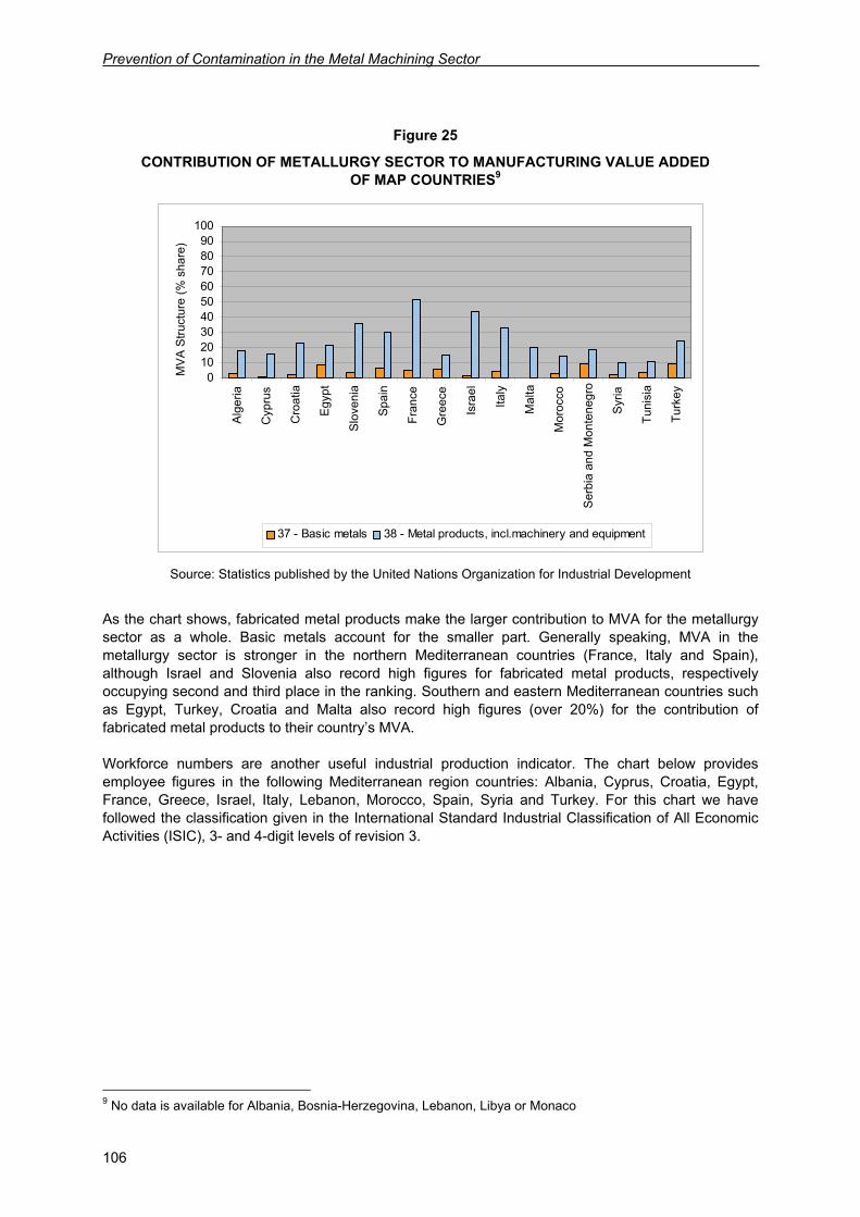
Prevention of Contamination in the Metal Machining Sector
106
Figure 25
CONTRIBUTION OF METALLURGY SECTOR TO MANUFACTURING VALUE ADDED OF MAP COUNTRIES9
0102030405060708090
100A
lger
ia
Cyp
rus
Cro
atia
Egy
pt
Slo
veni
a
Spa
in
Fran
ce
Gre
ece
Isra
el
Italy
Mal
ta
Mor
occo
Ser
bia
and
Mon
tene
gro
Syr
ia
Tuni
sia
Turk
ey
MV
A S
truct
ure
(% s
hare
)
37 - Basic metals 38 - Metal products, incl.machinery and equipment
Source: Statistics published by the United Nations Organization for Industrial Development
As the chart shows, fabricated metal products make the larger contribution to MVA for the metallurgy sector as a whole. Basic metals account for the smaller part. Generally speaking, MVA in the metallurgy sector is stronger in the northern Mediterranean countries (France, Italy and Spain), although Israel and Slovenia also record high figures for fabricated metal products, respectively occupying second and third place in the ranking. Southern and eastern Mediterranean countries such as Egypt, Turkey, Croatia and Malta also record high figures (over 20%) for the contribution of fabricated metal products to their country’s MVA. Workforce numbers are another useful industrial production indicator. The chart below provides employee figures in the following Mediterranean region countries: Albania, Cyprus, Croatia, Egypt, France, Greece, Israel, Italy, Lebanon, Morocco, Spain, Syria and Turkey. For this chart we have followed the classification given in the International Standard Industrial Classification of All Economic Activities (ISIC), 3- and 4-digit levels of revision 3.
9 No data is available for Albania, Bosnia-Herzegovina, Lebanon, Libya or Monaco
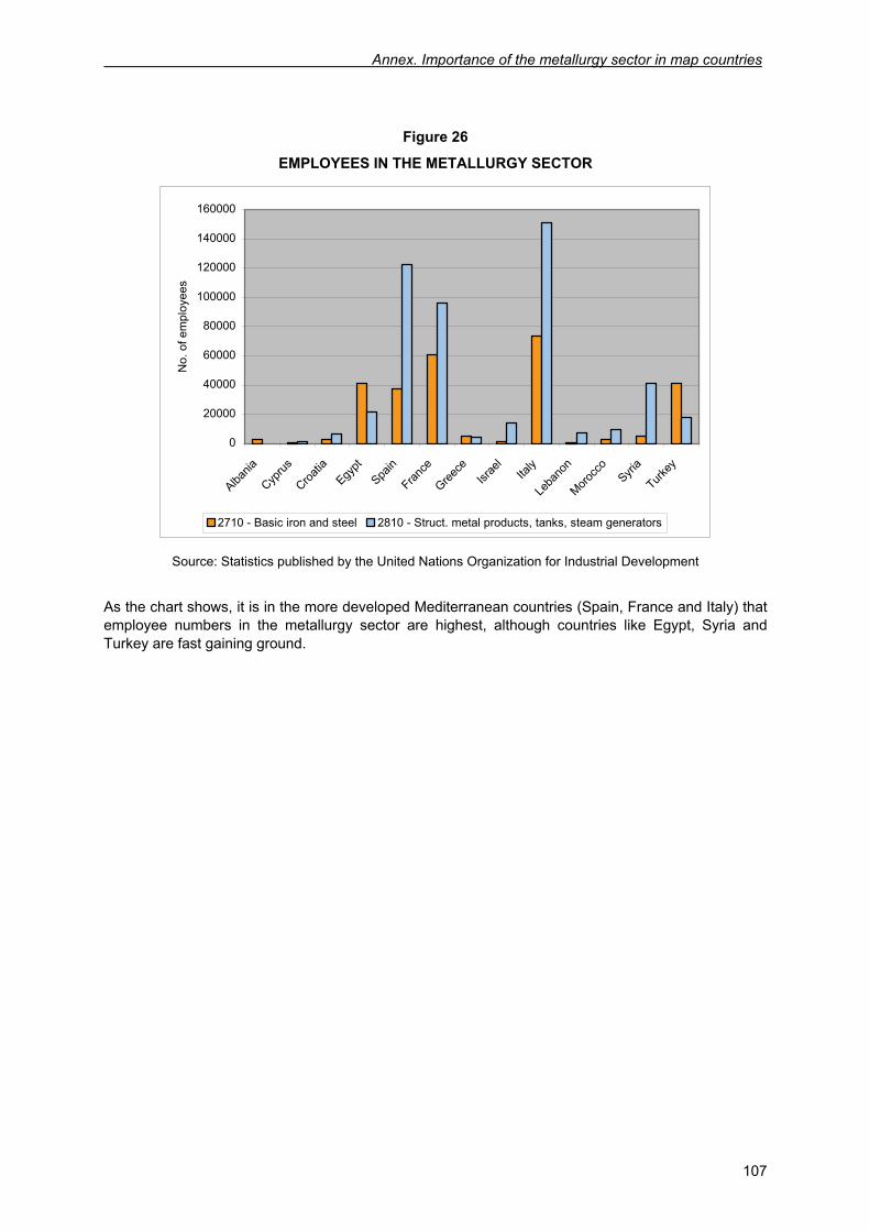
Annex. Importance of the metallurgy sector in map countries
107
Figure 26
EMPLOYEES IN THE METALLURGY SECTOR
0
20000
40000
60000
80000
100000
120000
140000
160000
Albania
Cyprus
Croatia
Egypt
Spain
France
Greece
Israe
lIta
ly
Leba
non
Morocc
oSyri
a
Turkey
No.
of e
mpl
oyee
s
2710 - Basic iron and steel 2810 - Struct. metal products, tanks, steam generators
Source: Statistics published by the United Nations Organization for Industrial Development
As the chart shows, it is in the more developed Mediterranean countries (Spain, France and Italy) that employee numbers in the metallurgy sector are highest, although countries like Egypt, Syria and Turkey are fast gaining ground.


Regional Activity Centrefor Cleaner Production (RAC/CP)París, 184, 3ª planta - 08036 Barcelona (Spain)Tel.: + 34 93 415 11 12 - Fax : + 34 93 237 02 86E-mail: [email protected]://www.cema-sa.org
tion
EAN