PRESTRESSED CONCRETE FENDER PILES: FENDER SYSTEM … · 2011-05-15 · o F F9 E cOP CR 89.005...
70
o F9 F E cOP CR 89.005 January 1989 An Investigation Conducted by ABAM Engineers Inc., Federal Way, WA Sponsored By Naval Facilities Contract Report Engineering Command AD-A206 496 PRESTRESSED CONCRETE FENDER PILES: FENDER SYSTEM DESIGNS ABSTRACT Designs for prestressed concrete fender piles for use at Navy piers in a wide range of fendering applications are presented. Two types of fender piles are discussed: an energy absorbing fender pile for use with camels and a reaction fender pile for use with foam-filled fenders. Complete fender system designs incorporating either timber or steel wales with the baseline energy-absorbing prestressed concrete fender piles, as well as a new class of fender pile to resist the reaction from foam-filled fenders, are presented. Design aids are given in the form of easy-to-use graph._s_ es examples are also presented. U TfC LECTE e6 MAp 18 89 3 06 '138. NAVAL CIVIL ENGINEERING LABORATORY PORT HUENEME CALIFORNIA 93043 Approved for public release; distrubution is unlimited.
Transcript of PRESTRESSED CONCRETE FENDER PILES: FENDER SYSTEM … · 2011-05-15 · o F F9 E cOP CR 89.005...
o F9 F E cOP CR 89.005
January 1989An Investigation Conducted by
ABAM Engineers Inc., Federal Way, WASponsored By Naval Facilities
Contract Report Engineering Command
AD-A206 496
PRESTRESSED CONCRETEFENDER PILES:
FENDER SYSTEM DESIGNS
ABSTRACT Designs for prestressed concrete fender piles for use atNavy piers in a wide range of fendering applications are presented.Two types of fender piles are discussed: an energy absorbing fenderpile for use with camels and a reaction fender pile for use withfoam-filled fenders.
Complete fender system designs incorporating either timber or steelwales with the baseline energy-absorbing prestressed concrete fenderpiles, as well as a new class of fender pile to resist the reaction fromfoam-filled fenders, are presented.
Design aids are given in the form of easy-to-use graph._s_ esexamples are also presented. U TfC
LECTE
e6 MAp 18
89 3 06 '138.
NAVAL CIVIL ENGINEERING LABORATORY PORT HUENEME CALIFORNIA 93043
Approved for public release; distrubution is unlimited.

0 n.' L
E ~ ~ o' e - 0-
0 ~ oa -£~Q4 " ..
I9 >i E 4,,,
At2~~~~~~ c w - tt~O . O ~
w 0~
(3 r E>ACL4
E E E. E E E,~. E. EE~ E Et Et 8 1 1 1'1~ I t I 0
09 I i ii r ~
19 8' 7 16 5 1,4,3 12 1 inches.
E EE~ E EE~~ E ECA _,E F 0
E2
c CI jI t; _ _ :
ii 0 d j

UnclassifiedSECURITY CLASSIFICATION OF THIS PAGE (iiok Oe.. Fnted)
REPORT DOUMENTATION PAGE READ INSTRUCTIONSBEFORE COMPLETING FORM. REPORT NUME 2. GOVT ACCESSION No. . .NCIPIMNT*S CATALOG NUMDER
CR 89.0054. TITLE (-d Sw6IIIIl) S TPC o
r OFRPORT a PERIOD COVERED
Prestressed Concrete Fender Piles: FinalFender System Designs Sep 1987 - AuR 1988
F PERFORMING ORG. REPORT NU.BE•R
7 AUTHOR(.j B. CONTRACT OR GRANT NUMBERN.)
N62474-84-C3140
B. PERFORMING ORGANIZATION NAME AND ADDRESS 10 PROGRAM ELEMENT PROJECT TASKAEA A 6 OK UNIT NUMBERS
ABA Engineers Inc.-001-02-01033301 Ninth Ave SouthFederal Way, WA 98003-63951 CONTROLLING OFFICE NAME AND ADDRESS 12. REPORT DATE
Naval Civil Engineering Laboratory 4anuarv 1989
Port Hueneme, CA 93043-5003 78 %,ERO,1178I4 MONITORING AGAOIlESS(,I 4rfl.,.t. Ira Co'"c' 0II ". ' 011, 1 5 'S SECURITY CLASS lof th-I reoIt)Naval Facilities Engineering Command200 Stovall Street Unclassified
Alexandria, VA 22332-2300 ,SCEDCLESS'"C"°O DOWNORAO.G
i DISTRIBUTION STATEMENT (,t IA. Report)
Approved for public release; distribution is unlimited.
17 OISTRIMUTION STATEMENT (ofIA *Ah IS 0 .111-1 ~ - Io P13T1h 20. It dife'II.I 1 R.P-e)
t$ SUPPLEMENTARY NOTES
19 KEVwOpDS Co,,,,., ,nd, 0 , 1 ~ PsI ,d d.-, bQ .10 -l ,
prestressed concrete, concrete, fenders, piles, fender piles.
Z0 A0STRACT (Cs nI * an * t I. l , 0 , 6,en Al b61.1h flIbnj
- Designs for prestressed concrete fender piles for use at Navypiers in a wide range of fendering applications are presented.
Two types of fender piles are discussed: an energy absorbingfender pile for use with camels and a reaction fender pile foruse with foam-filled fenders.
Complete fender system designs incorporating either timber or
DO I , 1473 . .. 1.. o .F, .I1NO NI IS O CSo C i f
SECURITY CLASSIFICATION OF THIS PAGE Rh" Dos E TI.red

Unclassified84UmT CLASOVICAION or rwis PAagm.. Dwe Ca...d)
steel wales with the baseline energy-absorbing prestressedconcrete fender piles, as well as a new class of fender pile toresist the reaction from foam-filled fenders, are presented.
Design aids are given in the form of easy-to-use graphs.Design examples are also presented.
Unclassified
TABLE OF CONTENTS
SectionPaoqe
1 SUMMARY.............................................. 1-1
2 INTRODUCTION......................................... 2-1
3 FENDER SYSTEMS DESIGN AND DETAILING ..................... 3-1
4 REACTION FENDER PILE DESIGN ........................... 4-1
4.1 Introduction .................................... 4-14.2 Design Criteria.................................. 4-24.3 Pile Reinforcing Configuration ..................... 4-2
5 REACTION FENDER PILE DESIGN AIDS....................... 5-1
5.1I Purpose of Design Aids ........................... 5-15.2 Theory and Development ........................... 5-25.3 Design Aid Figures ............................... 5-35.4 Design Procedure................................. 5-3
REFERENCES........................................... R-1
NOTATIONS............................................ N-1
Appendix
A DRAWINGS............................................. A-I
B CALCULATIONS ......................................... B-1
LIST OF FIGURES
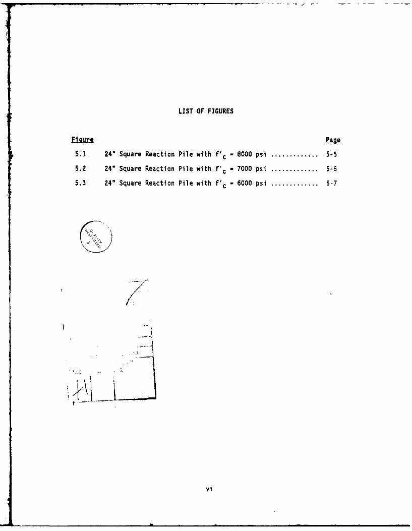
Figure Page
5.1 24" Square Reaction Pile with f'c 8000 psi ............. 5-5
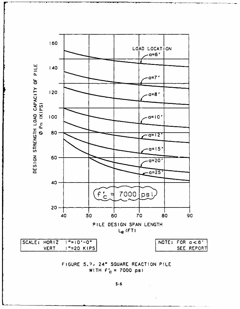
5.2 24" Square Reaction Pile with V'c 7000 psi ............. 5-6
5.3 24" Square Reaction Pile with V - 6000 psi ............. 5-7
-9,I
/-
t.,-.." -
i__i

SECTION 1
SUMMARY
The Department of the Navy, through the Naval Civil Engineering
Laboratory (NCEL) at Port Hueneme, California, has initiated a program to
develop prestressed concrete fender piles for use at Navy piers in a widerange of fendering applications. This report completes the design
portion of the multiphase testing, analysis, and design effort [1.1].
Two types of fender piles are discussed in this report: an energy-
absorbing fender pile for use with camels and a reaction fender pile for
use with foam-filled fenders.
Complete fender system designs incorporating either timber or steel wales
with the baseline energy-absorbing prestressed concrete fender piles are
presented. The system designs were developed from conceptual studies
performed in Phase IV of this study (1.2].
Design of a new class of fender pile to resist the reaction from foam-filled fenders is presented. Design criteria and design aids were
developed for a 24-in.-square prestressed precast concrete pile withconcrete strengths of 6000, 7000, and 8000 psi. The design aids are in
the form of easy-to-use graphs. A design example is also presented.
As a result of this phase, detailed drawings of complete fender systems
and design aids for a new class of fender pile are available to assist inprocuring precast prestressed concrete fender pile systems for Navy
facilities.
1-1

SECTION 2
INTRODUCTION
To encourage and promote the use of energy-absorbing precast concrete
fender piles it is necessary to develop system details that may be used
by engineers to incorporate them into complete designs. The systems
oresented herein are very similar to those used at existing Navy
facilities. The details are alsu prepared with the thought in mind that
these fender piles can be adapted to existing timber or steel fender
systems without significant changes to existing chock and wale systems.
The fender systems are discussed in Section 3.
The concrete reacti-on fender piles serve to transfer the reactions from a
foam-filled fender into the pier or wharf and harbor bottom. Energy
absorption of a foam-filled fender is sufficient in itself. Energy
absorption by the concrete piles adds to the system overload capacity.
In an effort to minimize costs yet provide the necessary performance and
durability requirements established in previous phases and to make more
efficient use of the prestressed concrete piles as reaction piles, the
design criteria developed in previous phases were reevaluated. The
reaction fender piles selected are discussed in Section 4.
2-1
SECTION 3
FENDER SYSTEMS DESIGN AND DETAILING
The two fender system designs presented in this report employ the proto-
type energy-absorbing concrete fender pile that was developed in previous
phases of the study. The standard pile is 18 in. square and is
prestressed with twenty 1/2-in.-diameter strands in a rectangular
pattern. Depending on the site-specific conditions and the required
system energy, a different size pile could be used. For more specificinformation on the pile design itself, refer to Phase III of this study
[3.1].
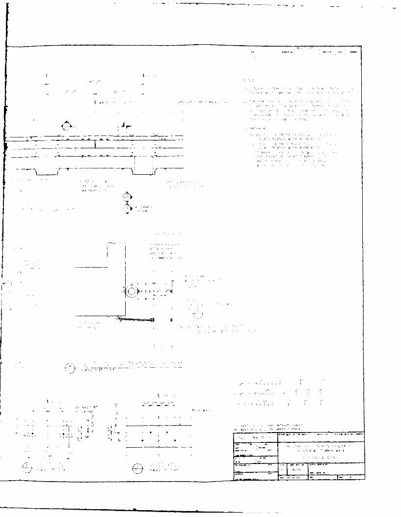
The drawings for the fender pile systems are contained in Appendix A.
Two schemes are presented: Alternate 1 uses timber wales and Alternate 2incorporates a steei W-section wile. The timber wale system will be less
expensive initially than the steel wale and long-term maintenance for the
timber wale will be less.
The assumptions used in developing the fender system alternates are
. The berthing energy of the ship is absorbed entirely by the concrete
fender pile.
The fender pile is contacted by the ship only at the water line and
not at the top of the pile. This requires either a log camel or some
other type of floating separator between the ship and the pile. (Apartial detail is provided for use when this assumption is not met.)
* The system details are developed for new facility construction but can
be easily adapted to existing facilities.
The system elements common to both alternates are listed below:
3-1

* Timber chocks
* No rub strip on the pile face
* Pile spacing - 8 ft
Following is a discussion of critical components of the system and their
purpose:
The fender system is designed so that the fender piles absorb all the
berthing energy; therefore, rubber fenders behind the piles at the deck
level are not required. Rubber fenders are needed when the pile acts as
a "reaction pile" and transfers the berthing force up to the pile top and
into the rubber fender, which in turn absorbs the energy. Rubber fenders
would also be required if a camel or separator were not used to berth a
ship, and the ship contacted the pile top directly.
In the case where the fender pile absorbs the energy and the rubber
fender is omitted, the fender system (i.e., wale and chock) can be
supported directly off the pier rather than off the fender piles. The
fender pile is then held against the chock and wale with a restraining
strap. The advantage of this system is that if some piles are broken,
the remaining fender system has not lost its vertical support.
The pile is held against the wale using a steel strap that projects
slightly beyond the face of the pile. Should a vessel berth directly
against the top of the pile, consideration should be given to protecting
the vessel and strap. There also would be no energy absorption possible
in the system. This emphasizes the need for a camel or separator. It
may be advantageous to project the chock beyond the face of the pile to
prevent ship contact with the steel strap, which ceuld damage both the
ship paint and strap around the pile.
A method of attaching Lhe wale to the pier is presented in the drawings.
A T-bolt insert is cast in the face of the concrete pier. The 1-in.-
diameter T-bolt can then be installed and rotated 90 degrees and locked
in place. The holes for both the blocking and the wale should be drilled
3-2
based on the as-built location of the T-bolts. Other options for
attaching the wale to the pier include screw anchors, coil bolts, and
drill and epoxy bolts in the pier face. Anchor bolts could also be cast
in the pile cap or bullrail with the ends projecting out. This may not
be as desirable because it requires holes to be drilled in the side of
the formwork.
The T-bolt or other connector that supports the wales must be properly
tightened. The longitudinal forces that may be imparted to the fender
system due to berthing must be resisted by both friction between the wale
and blocking, and the blocking and pier. The component of longitudinal
force normal to the pier increases the friction resistance of the fender
system. The shear capacity of the bolt alone is small due to the fact
that the blocking behind the wale may allow bending in the bolt if the
friction force is overcome.
The purposes of the blocking between the pier and the wale is to provide
a means to adjust for irregularities in the bullrail. This offset also
provides access to the bolts that connect the chock and wale together and
the wale splices. The blocking could be either solid rubber or timber.
Another possible option is to omit the wale and attach the chock and pile
and blocking directly to the pier face with through bolts and screw
anchors. This option is less desirable than methods previously described
because field drilling of the precast prestressed concrete pile may be
required in order to line up with the screw anchors.
If rubber fenders are used between the wale and the pier, the wale is
usually designed to distribute the reaction from the pile top into
several rubber fenders. When a solid block is used behind the wale in
place of the rubber fender, there is no distribution of force. In this
case the wale and blocking provide a standoff between the pier and pile.
The minimum standoff might be controlled by the ability of the pile
driving equipment to drive close to the pier. There might also be a
minimum distance required between the outboard support pile of the pier
3-3
structure and the fender pile. The timber wale is shown as two piecesrather than one large piece but either option may be used. The type oftimber wale used will depend on regional timber availability and costs.
The purpose of the chock is to restrain the pile from moving along thepier face and to keep it from twisting in plan. To accomplish this, thetimber chocks should be cut for a tight fit. Because of their shortlength, the chocks are to be one-piece units.
The chock and wale are designed to support personnel walking on the
fender system. If it is necessary to support additional live load(cables, steam lines, etc.), the connection of the wale to the piershould be reevaluated.
For the timber wale alternate system design with rubber fenders behindthe head of each pile, the fender system is attached directly to thepile. The pile is then held against the pier by a chain that connects toa steel hardware unit cast into the pier. The most positive method ofattaching the chock/wale to the pile is to use a through bolt. Thedetail for the through bolt requires more accurate driving tolerances
than the steel strap does. The through bolt also presents more of afabrication problem because of the number of strands in the pile. Inorder to resist the longitudinal forces, a set of horizontal chains isrequired at certain intervals to transfer the force from the wale into
the pier.
3-4
SECTION 4
REACTION FENDER PILE DESIGN
4.1 INTRODUCTION
Foam-filled fenders are used extensively in the Navy for both absorbing
the energy due to ship berthing and as a standoff between the ship and
the pier structure when the ship is moored. Currently, there are many
different methods of transferring the reaction of the foam-filled fender
to the pier structure. In Phase IV of this study [1.2], different
concepts were presented using a 24-in.-square prestressed concrete fender
pile as a reaction pile behind a 6-ft-diameter by 12-ft-long foam-filled
fender. The purpose of this section of the report is to develop design
criteria and design aids for the 24-in.-square pile as a continuation of
the previous phase.
The foam-filled fender is assumed to absorb all the required energy from
ship berthing. The reaction associated with the berthing energy is
transmitted through the foam-filled fender either directly into the
concrete reaction piles, or into a bearing panel to help distribute the
loads to the piles. The actual contact length over which the foam-filled
fender will deliver the reaction force must be taken into account.
The pile is designed as a "stiff" member, transferring the reaction from
the foam-filled fender into the pier and harbor bottom. The design
includes a higher level of prestress force with fewer strands than did
the "soft" pile, whose primary purpose was to absorb energy, not to
transfer a reacti. '. The "stiff" design results in a more economical
pile to resist a reaction force than the "soft" pile but it does not have
the energy absorption capability.
4-1

4.2 DESIGN CRITERIA
The horizontal force on the pile due to the foam-filled fender reaction
could result from a static or dynamic force. The static force could be
from either wind or current. The dynamic force would result from
berthing the vessel. Regardless of the origin of the force, it must be
factored to obtain an ultimate load (versus a working load) to be used in
the reaction pile design.
The energy absorbed by the "stiff" pile is not counted on in the design.
For static loads, energy is not a design parameter and for dynamic loads
the foam-filled fender is assumed to absorb all the energy. Therefore,
energy absorbed by the pile is not critical but adds to the overload
capacity.
The "effective" number of concrete piles required to resist the ultimate
Teaction force is not necessarily the number of piles that must be pro-
vided. The word effective is used because the designer must calculate
the actual distribution of load to each pile. The "system design" is
analogous to a beam on elastic foundation, which may result in some piles
being more heavily loaded than others. If a bearing panel is required,
the load distribution also changes. The pile loaded with the highest
reaction in the system will control the design. See the previous phase
of this study for items to be considered [1.2].
4.3 PILE REINFORCING CONFIGURATION
The pile is designed as a vertical flexural member, not a compression
column. The "stiff" pile concept developed in the previous phase was
chosen over the "soft" pile concept. For details of the design, refer to
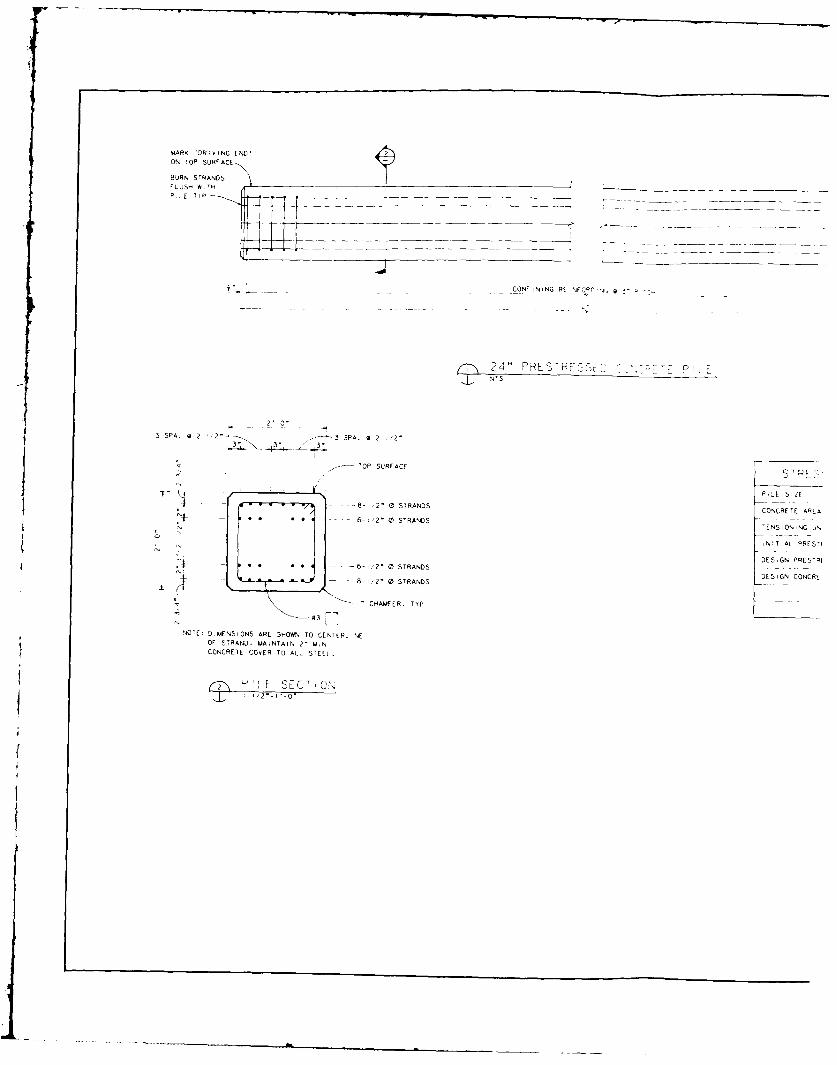
the previous phase of this study. The design drawing for the 24-in.-
square reaction pile is found in Appendix A. A total of twenty-eight
1/2-in. strands are used along with No. 3 confining steel.
4-2

SECTION 5
REACTION FENDER PILE DESIGN AIDS
5.1 PURPOSE OF DESIGN AIDS
Design aid figures (Figures 5.1, 5.2, and 5.3) are presented to assist
the designer in selecting the number of "effective" piles required to
resist the reaction from a foam-filled fender or other marine fendering
unit. This report addresses the design problem from the point of knowing
the maximum factored force imparted by the fender into the pile.
The issue of what design criteria should be used to design the marine
fendering unit is beyond the scope of this report, but must be dealt with
in the context of arriving at the factored loads. The derivation of the
maximum factored force applied to the pile due to wind, current, and ship
berthing is also beyond the scope of this study. The important require-
ment for designing the concrete reaction piles is that the loads must be
factored loads, not working loads.
Some general points to be considered are
0 The designer must calculate the factored (or ultimate) loads for both
wind plus current and berthing.
a If the maximum factored loads are close to the maximum rated reaction
of the marine fendering unit, use the rated reaction for the reaction
pile design.
m If a larger fender than required by reaction design is used to provide
a standoff between the ship and pier, and the actual factored loads
are much smaller than the rated reaction of the fender, use the maxi-
mum factored load for the reaction pile design.
5-1

* Consideration should be given to the tolerances allowed by Military
Specifications [5.1] for the maximum rated reaction when using the
rated loads.
5.2 THEORY AND DEVELOPMENT
When using the design figures to select the number of reaction piles
required, the design load must be considered as a factored ultimate load
and not a service level load. Military Handbook 1025/1 [5.2] gives
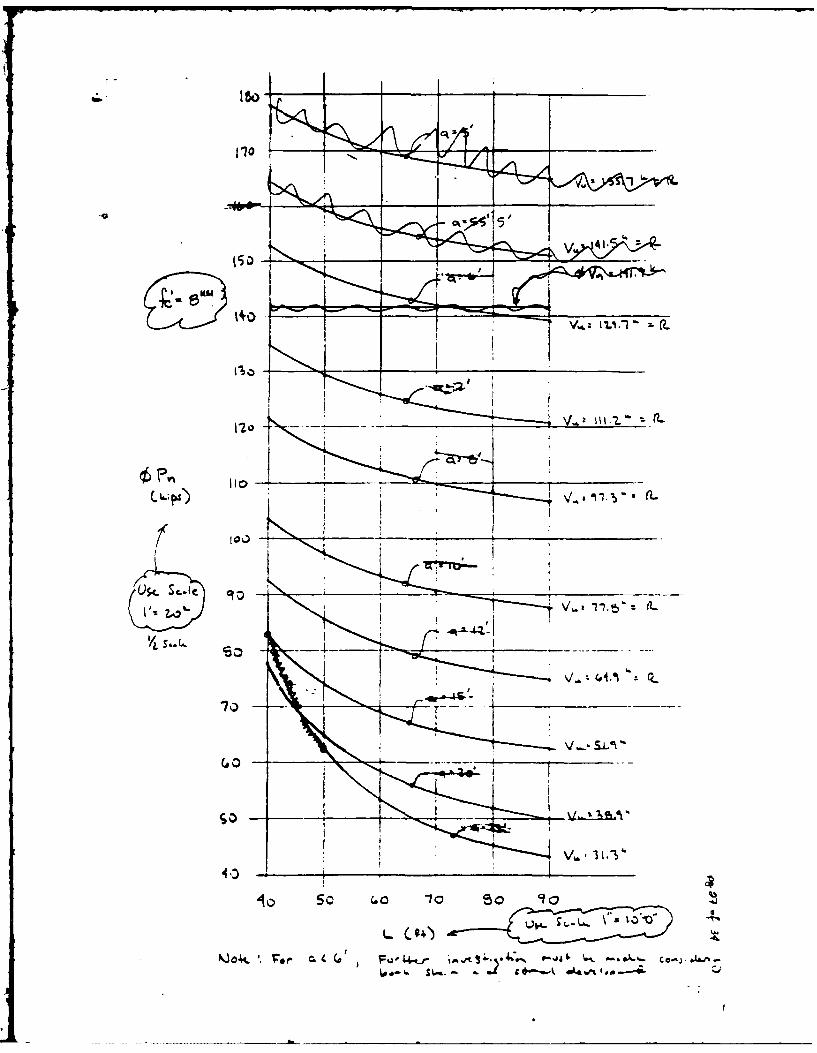
guidelines for the ultimate load factors to be used. Figures 5.1, 5.2,
and 5.3 present plots of the "design strength load capacity" versus the
wdesign span length" of the piles.
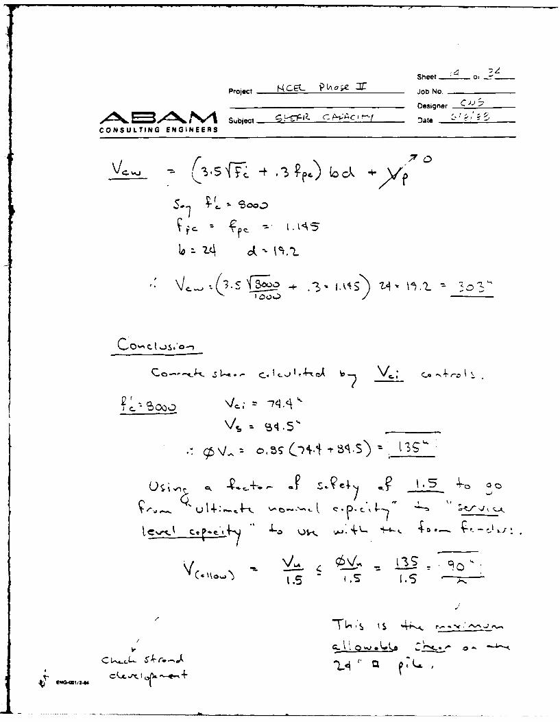
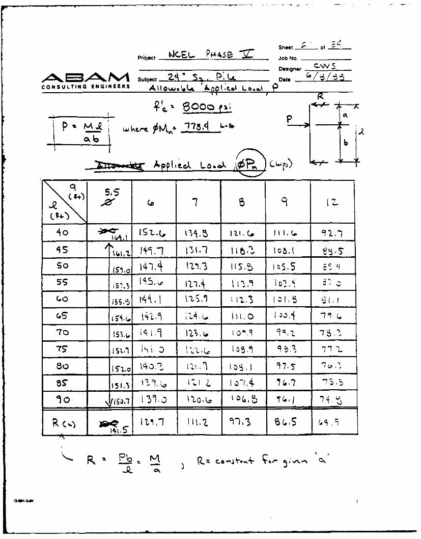
The pile load capacity is limited by the moment capacity of the section
for a given concrete strength when loaded no closer than 6 ft from the
support. This 6-ft dimension is based on the assumption that the top of
the pile extends a mirimum of I ft beyond the support. When the pile is
loaded closer than 6 ft, the load capacity should be calculated. Load
capacity will be limited by either the shear capacity of the section or a
reduced moment capacity due to the strand development length available.
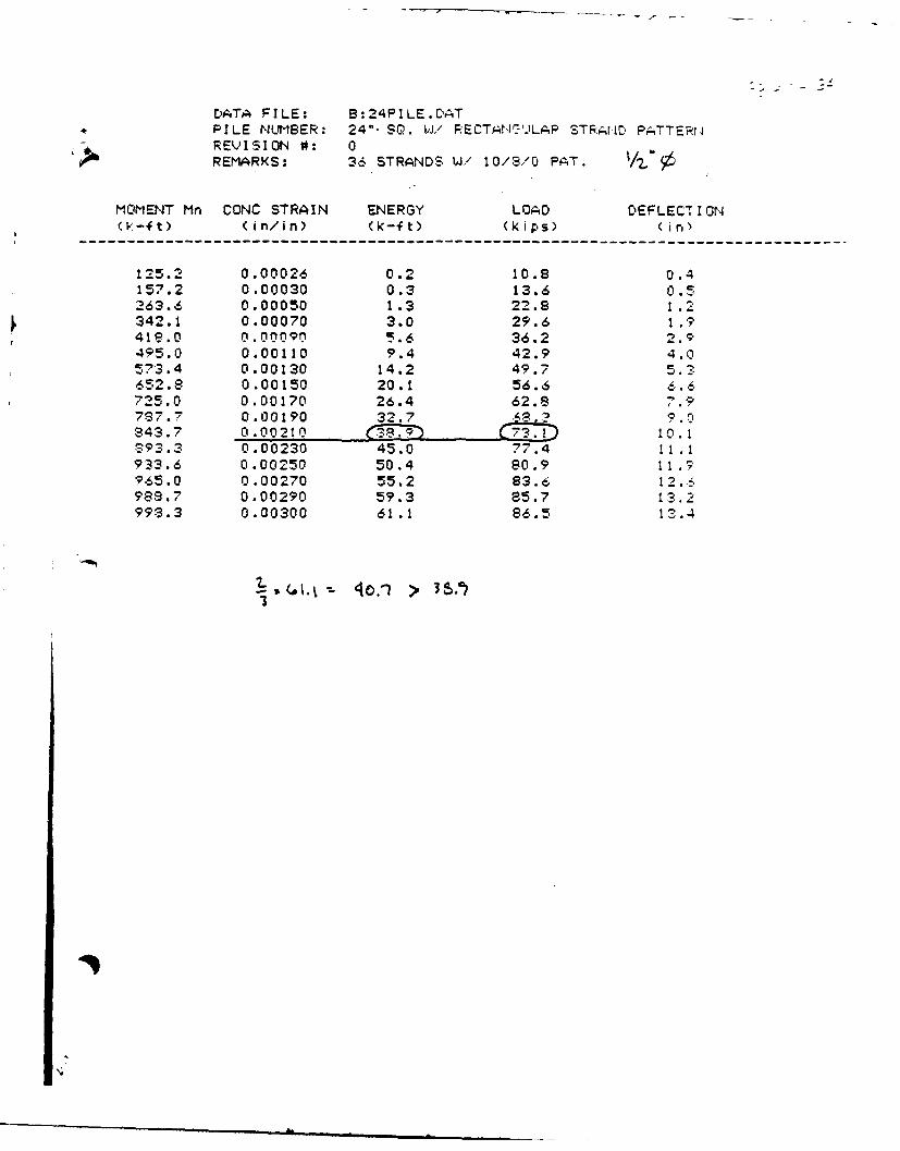
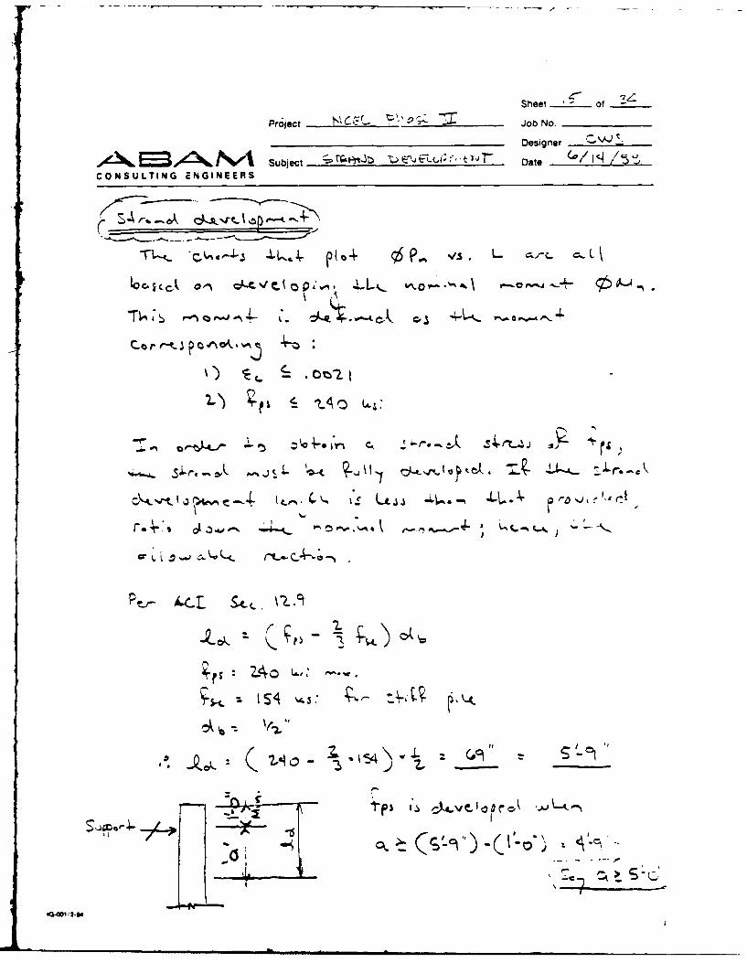
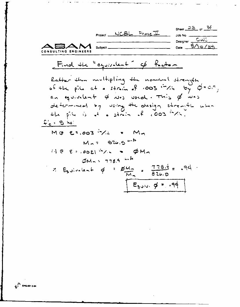
The controlling moment capacity In the pile is defined as "the moment at
which the extreme fiber concrete compressive strain is equal to
0.0021 in./in. if the maximum strand stress is less than 240 ksi." Piles
similar to the reaction piles have been load tested and shown to perform
well under cyclic loads producing the above-mentioned strain. In lieu of
taking the ultimate capacity of the pile at the design code strain limit
of 0.003 in./in. and multiplying it by a strength reduction factor (0),
we have chosen the moment at this lower strain as the ultimate factored
capacity.
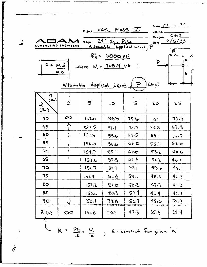
The moment capacity of the pile is constant for a given concrete
strength, and does not depend on pile length or load location for loads
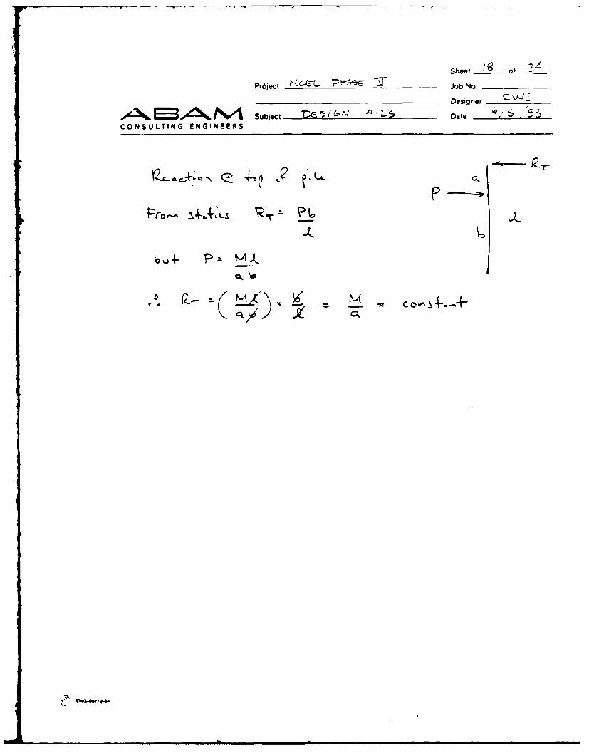
applied greater than 6 ft from the support. The corresponding reaction
is a function of this moment capacity and varies with pile span length
5-2
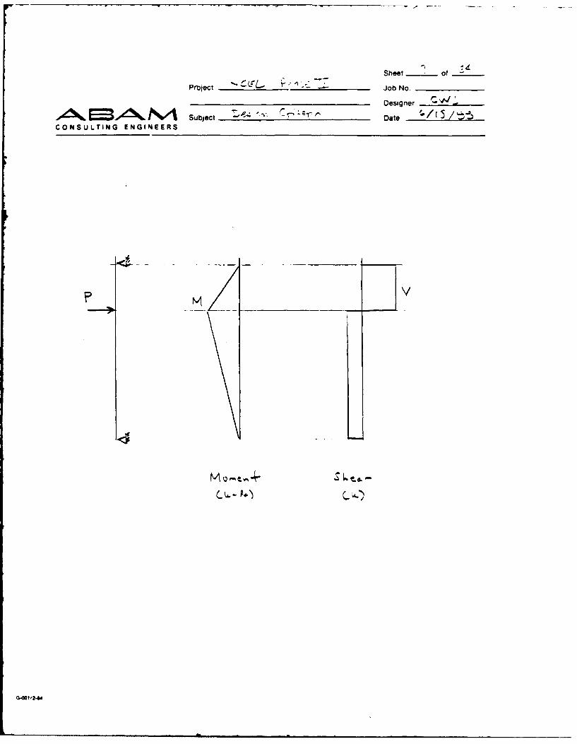
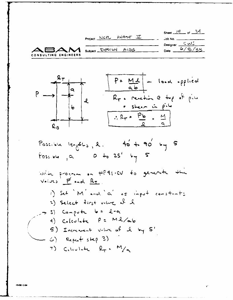
and load location. The corresponding pile reaction into the pier can be
calculated by statics and is equal to the shear in the upper portion ofthe pile. This reaction should be used to check the strength of the
existing or new wharf to accommodate the fender reaction.
5.3 DESIGN AID FIGURES
The figures developed in this report are intended for pile support
lengths varying from 40 to 90 ft. The range of pile load locations
ranges from 6 to 25 ft below the top support. Plotted on the charts arenominal load capacity curves for particular load locations versus pile
support lengths. The three charts provided are for concrete strengths
(f'c) equal to 8000, 7000, and 6000 psi and are used to calculate the"effective* number of piles.
5.4 DESIGN PROCEDURE
The procedure to select the number of effective piles follows:
Step 1
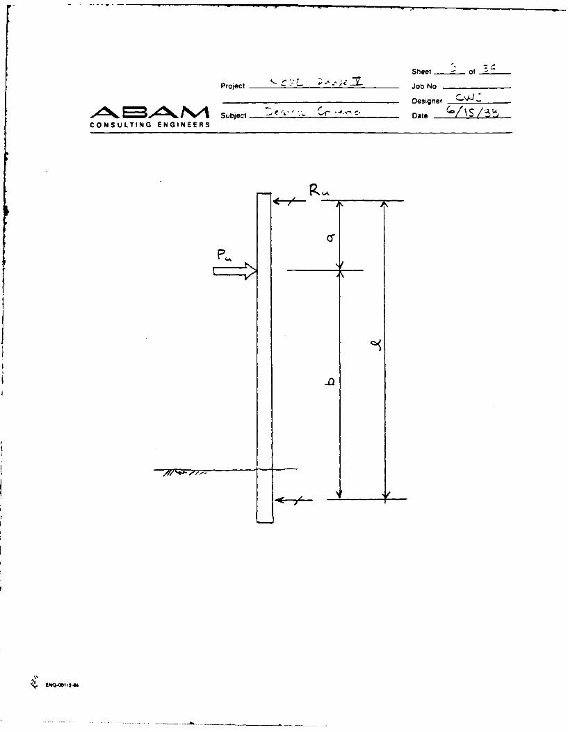
a) Determine the pile span length, Le.
b) Determine the maximum and minimum value of "a," which depends on
where the reaction from the foam-filled fender or other marine
fendering unit will contact the concrete pile due to tidal
variations or other factors (i.e., the fender may also be hung from
the structure rather than floating).
c) Choose the pile concrete strength, f'c, and refer to the appropriate
figure.
5-3

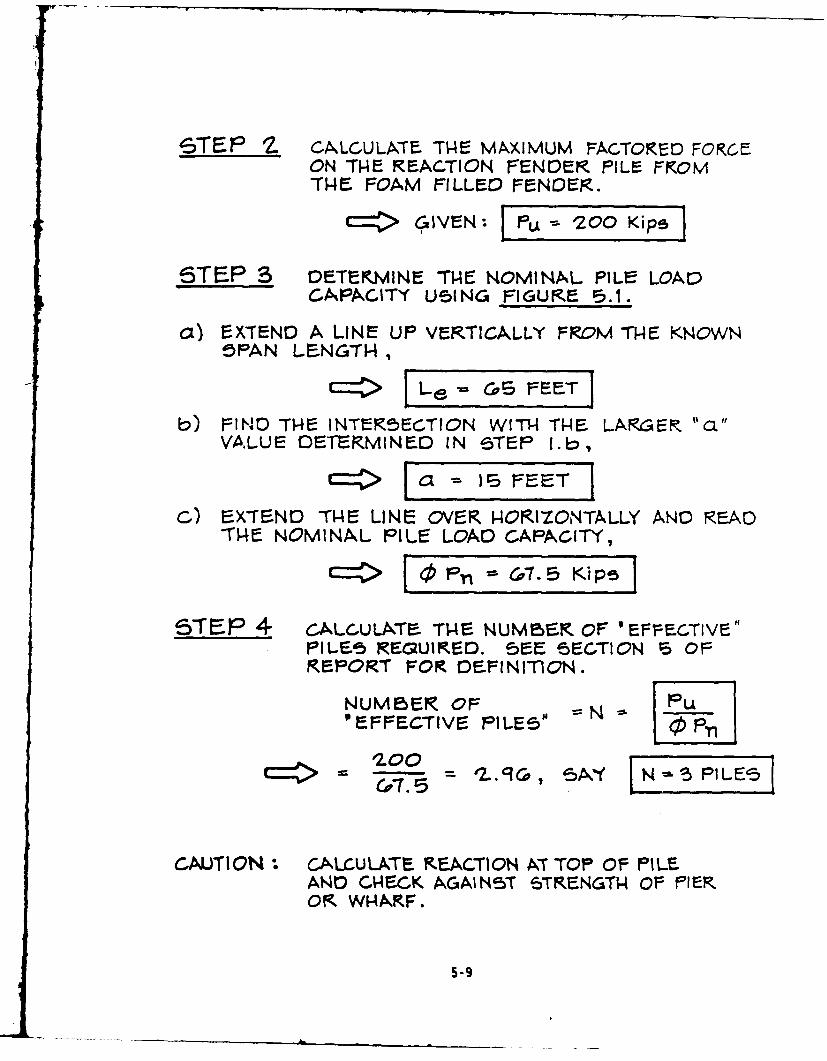
Step 2
Determine the maximum rated reaction that results when the foam-filled
fender is at 60% compression. This criterion may vary for other types ofmarine fendering. This will be treated as the ultimate load. Check that
the factored loads due to wind, current, and berthing are less than the
foam-filled fender rated reaction. Refer to Section 5.1 for further
explanation.
Step 3
Knowing the pile span length, extend a vertical line up through the two
extreme load locations. Follow the intersection of the lines horizon-
tally and read the pile reaction capacity.
Step 4
The "effective" number of reaction piles required is equal to the ulti-
mate load divided by the smallest pile capacity found in Step 3.
5
5-4

I140
a=-
-
C-,<---
S - 0
z
z - 0
20
40 50 60 70 80 90
PILE DESIGN SPAN LENGTHLe (FT)
SCALE: HORIZ 1"=10O-O' NOTE: FOR a <6'VERT I"=20 KIPS SEE REPORT
FIGURE 5.1, 24" SQUARE REACTION PILEWITH f'c 8000 psi
160
-J 140
CL<
C
~a 100
00
40-
20
40 50_ _ _0__080_9
PIEDSGzPNLNTLe(FT
SCL:HRZ 1=0-O OE O 6VET 1=0 IS EERPR
FIGUR PIL DE, 4 SIGNR SPATO LENGT
WITH fc= 7000 psi

I60
140-LOAD LOCATION
-
.
0=1
80-
z 6
40
40 50 60 70 80 90
PILE DESIGN SPAN LENGTHLe(FT)
SCALE: HORIZ 1"=10'-O" jNOTE: FOR a <6'VERT 1"=20 KIPS I SEE REPORT
FIGURE 5.3, 24" SQUARE REACTION PILEWITH F'C 6000 psi
5-7

DE51GN EXAMPLE
STE1F I1HR TOP SUPPORT
I5'TO
MUDLIN4E KEACflON Le
WI4ARF5TKUCTUKAL I10ILE-S I' i 50,
I SS5UME 15
A5UMED LOCATION OFPINNED 5UPPOKT
ax) Le 5+ (+ 50') J~b) aL VARIaE5, RANGE5 FROM:
MINIMUM a IS'- 5]MAX(IMULM CL I1S'- 0' [J
C,) 5PECIFY THE '28 DAY 6TRZENGTH OF THE- CONCRETEFILE A-5 fL -8000 peL. -THERE-FORE USE2
ODESIGN AID IUR .
5-8
6TEP S1 CA.LCULA-TE. THAE MAXIMUM FACTOKREC FOCEON TH-E REACTION FENDER PILr= FOM
rHE4 FOAM FILLED0 FEN015R.c= GIVEN: -- "=200 Kips
ST EP 3 DE-TEKNINE TI-e NOMINAL PILE LOADCAPACITY U51NG FIGURE 5.1.
a) EXTEND A LINE UP VERTICALLY FROM THE KNOWN5PAN LE.NGTH,
L, - S ETIb) FIND THE INTEK5ECTION WITH4 TH-E LARGER. "ai
VA4LUE DETERMINED0 IN STEP I.bw
C=:> IS FEET
C) EXTEND TI4E LINE OVER P-ORIZLONTA-LLY ANO READ)114E- NOMINAL PILE LOAD CAPACITY,
C=: ,'-&1 LIZ~ K!Pi5STE~ 4 CALCULATE. TI-NumBE.oF 'E~rEFcTivE"
PILES4 REQRUIKED. SEE- 5ECTION, S OFREPORT FOR DE.FINrnOIN.
NUMBER OF V P 70EFFECTIV5 PILES"
CAUTION CALCULATE KEACTION XT TOP Or- PILEAND CHNECK AGAIN5T GTRENGTN Or- FIEROK WHAXF.
5-9

LOAD LOCATION
EAMPLe a-7'
O 120 PROBLEM __ __
008
0-
80
zLi
=1
20
SCALE: HORIZ 1"=10'O' NOTE: F~~T OR a<6'
IVERT 1"=20 KIPSI E REPORTI
FIGURE 5.1, 24" SQUARE REACTION PILEWITH fc 8000 psi
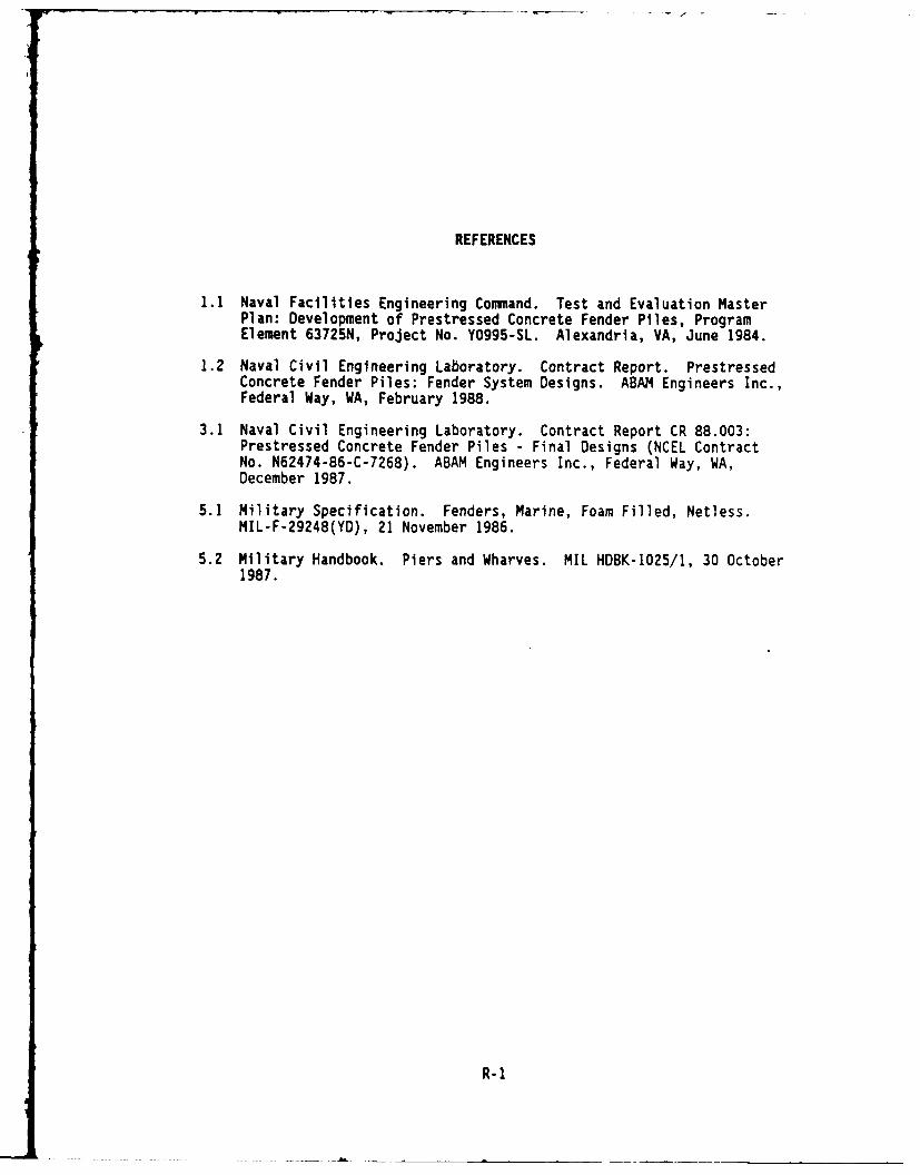
REFERENCES
1.1 Naval Facilities Engineering Command. Test and Evaluation MasterPlan: Development of Prestressed Concrete Fender Piles, ProgramElement 63725N, Project No. Y0995-SL. Alexandria, VA, June 1984.
1.2 Naval Civil Engineering Laboratory. Contract Report. PrestressedConcrete Fender Piles: Fender System Designs. ABAM Engineers Inc.,Federal Way, WA, February 1988.
3.1 Naval Civil Engineering Laboratory. Contract Report CR 88.003:Prestressed Concrete Fender Piles - Final Designs (NCEL ContractNo. N62474-86-C-7268). ABAM Engineers Inc., Federal Way, WA,December 1987.
5.1 Military Specification. Fenders, Marine, Foam Filled, Netless.MIL-F-29248(YD), 21 November 1986.
5.2 Military Handbook. Piers and Wharves. MIL HDBK-1025/1, 30 October1987.
R-1

NOTATIONS
a Distance from support at pile top to location of loadapplication
f/'c Specified compressive strength of concrete
Le Pile design span length calculated from centerlines ofsupports
N Effective number of piles
Pn Nominal load capacity of pile
Pu Factored (ultimate) force applied to pile from reaction ofmarine fendering unit
Strength reduction factor
@ Pn Design strength load capacity of pile
F:A86094
N-1

APPENDIX ADRAWINGS

I,.
'P K _________
?~ T ______ ,.- -~
~~'1"~~~~ -r
F-i
4'
~
I .,~.>. ~...,.-.. - --'I -. * 4 -. A.
IIU. r
-U -J
- .- - . '.'A
4' '.. '"''-3
_________ - 4 -
S--3'- - 4
- 1
7'-- -.
3-. '
'4
. A'. S.3~3'
I 4' 'H'. '''A -I . 9
* . . -. .34
J ______________________________ *..~>3;'' '..
A Yb>A 44>
'A..
- '3'- ~4,3 3-,-----I

0COCE IF N ISFF'P
'0 FE BOLT4r P *SF R'
OP EQULL P -
CCTA' .; w--I*
* 4,.8?
'C5T TE E hE_ I
UU-=
'F F. -- CC CF7
CROD
-2 SCALE: 314'
S-BCE NO
F CC
L, 2 B- ,0
-, "ISOA
F .F X
4 5' L,3 .F........
C~ SCALE:

PLE
B -U.NO'F FC
40. F ENDER fS7STEMv S DE S OTE D JF NE w CCT.S'P C I3'.I.
-- BL CC' I N ANCHOR BCE TS MAY BE KOED N P_ AU OF 'TE -BC. 5.
*AESP E2. THE PRESTRESSED CONCRE 'E FFNOFA I .EEWAESP ETO ABSORB A. THEF BERTHINO ENERGY UF THE S-0.C-WN .,ALL HORIZONTAL FORCES '-OM THE S' P SHO,.. BE
TRANSFERRED '0 'H'E P _F A' TH[ *ATER- %E OF T,
A -~'2 -~THE JSE CF A CAME. SYS'; M.
H.-.3. MATERIALS
A . BOLTS - AS'M A307, -O'-D CA GA'.A
N AC CORDANCE W - ASTY A 53''*B. ST EL- ASTM A-36, HO'-O P CA. DN
HARDWARE IN ACCORDANCE * T- A5'M A TT
AND SHAPES IN ACCORDANCE A ', RE". A 2 3.C. TIMBER P AEC,C COAST DCC 5AS A.P
PRESERVAT AE TREAT TIMBERS US NCG
7WATER-BOR NE SALTS N ACCORDANCE
W-A" SPECEF CAT !ON SE'CTION 0289
D. A..TERNATE S'EEL PROTECA>, CEOAT NCG
-I4 yi0~ E. C0B '5 A 1"R8" SOUARE H..COAT ALL STEEL S HARPES AND HARDWARE A '
MACA BE RON _ CDCR' H .'RAL TAR E PoxA. APR.AL 3.0 M1_ VD-. RA ME
WVASHERS. YP 'CMPAT.BLC A "' TOP COAT AND B.C MCOAT CE COAL TAR EPOXY. 1 PROTEC' .E
* . ~COAT ING HAS BEEN DAMAGED, REMOVE PA 4T
SYSTEM IN DAMAGED OR HEAT ArEClED AREAC
BPOWER-A RE BRASH-NO. OR OTHER AAAAOVED
METHODS. 'MMEDIATE-Y APPLY A B8 NC" MOE'T
COR' 01 NON-OARY NC CORE 'R- BASED MATC'CONCOAM1% NC 'EE3 SPEC, SS C- 53. 'ARE 2.
~ 42'
3
PC 3~" -- O D
PRE 51AT PC 0'D-NRET "
..3 '1 YS- WT'' "' *A I
"A NO
ARK ODR VNO END'ON TOP SURFACE
BURN STRANDS
CONEINING RE NFTPr
2 24 PRE 'S R, ED I
3 SPA. 9 2 2- --- 3 SPA. a 2 '2
~-TOP SURFACE
- -- 8- 1 2 0 STRANDS CONCRETE AREA
5-- 0 STRANDS -ENSIONINO N5'j~~ N N AL PRE S'
1-~1,? - . ---. STRANDS DESIGN COREl-- --- 8-: ?' 0 STRANDS -DE S OGN CRESAI
---CHAMFER. T P
NOTE: D MENSIONS ARE SHOWN TO CENTER- NEOF STRA ND. MAINTAIN 2- M.NCONCRE TE COUE R TO At S 5TEEL.
o D SELE CT i&%

R AES ONS
MARK TIP' ON NOTES:TOP SURFACE
P S I. TH S PRESTRESSED CONCRETE P..E
BURN STRANDS IS DESIGNED AS A REACTION P LEFLUSH WITH VERSUS A FENDER PILE.PILE TIP A REACT ION PLE TRANSFERS RCES
WHEREAS A FENDER PILE ABSORBS FNERG.--- 2. L:FTINO DEVICE LOCAT' NS ARE TO BE
DET ERMINED BY THE IABRpCAORCONSIDERING H ANL NC STRESSES
- -AND DR/ING REDUIREMENTS.
3. PRECAST CONCRETE PLES
- X 45° CHAMFER, -TV r'c - PSI AT 28 DAYS
4. CONCRETE STRENGTH AT PRESTRESS
t '" _.__ -TANSFER, 3500 PS MNIMUM.
5. RE NFORCEMENT
A. REBAR: ASTM A615, OR 60
B. PRESTRESSING STEEL: '2" - 27C KS'SEVEN WIRE . NCOATED. STRESS RE.LEVES
OR LOW RE: AXAT.ON STRANDS PER ASTM A4 6.
6. MARK EACH END OF P LE AS SHOWN.
. ... . _ _ -_ 7 . S E E S PE C JC A' ON S F O R A D D :T !O N A.P LE FABRICATION REQUIREMEN'S.
STRESS!NG DA T A
PILE SZE 24" 24'
CONCRETE AREA 56 IN'
'ENSIDNING UNITS 28 STRANDS
INITIAL PRESTRESS FORCE 810 KPS
DESIGN PRESTRESS FORCE 660 KIPS
DESIGN CONCRETE STRESS !'45 PSI
IF SHEET 5 'ESS THAN 28"X40 . S El'
HAS BEEN REDUCED. USE GRAPHIC SCALE.
NCEL 88-8-3F
, PRESTRESSED CONCRETE REA,' ON PILE
04" SO.IAAE F
"9" 6 " I"U - F BO
I ' ~ GrRHEI~R3 -1 - '-

APPENDIX BCALCULATIONS

Sheet _____of ____
Project C L s7Job No,________Designer
t~1Subject Date 1CONSULTING ENGINEERS
Sec.Ti 01, PAGE
eClr C- P ,4
ote co-pudec- rukv1s,

sheet____ of
Project - .. Job No. ______._J__O
Designer
oebE 'nk6Subject e oCCIDate
CONSULTING ENGINEERS
____ r. ' t-- e_(OOo O
o (3 Too to-

Sheet _ of
Project - Job No.
Designer C
144 P=RNNA Subject Date A_____CONSULTING ENGINEERS
Tp- / -0,' - -,,,
.~. .. ~,-.
7C ' .- s4t-.t I'
F/ -

PROJECTs NCEL FENDER SYSTEM STUDY W/ 24" PILES / cADATEs 12/1/87DESIGNERt CWPROGRAM# 'FENDER' DEVELOPED BY ASAM ENGR. INC.
. DATA FILE& , E2* PILE NUMBER, RECTPIGULAR STRAND PATTERN* REVISION *I, REMARKS, PAT.
* PILE DIMENSIONSt* LENGTH - 65 ft
SLOD FROM TOP - 15 ftDEPTH - 24 in
* WIDTH =" 24 InCONCRETE DATA W
* STRENGTH f'c - 8 KsiM MODULUS E " 4= 1 ki
* PRESTRESS fpc - psi* STRAND DATAi* STRAND TYPE - RELAXATION
0 S STRAIDS 26
* STRESS fpu ksi* STRESS fse -154 s** MODULUS E - 28000 Ksi* AREA - 1.224 sq.In DEPTH - 2.75 In* AREA - .918 sq.in DEPTH - 4.75 in* AREA - 0 sq.in DEPTH - 6.75 In
AREA - 0 sq.in DEPTH - 17.25 inAREA - .918 sq.in DEPTH - 19.25 in
* AREA - 1.224 sq.in DEPTH - 21.25 in
MOMENT Mn CURVATURE CONC STRAIN UPPER STRAND LOWER STRPID N DEPTH
(K-ft) (rad/in) (in/in) STRESS (Kst) STRESS (Ksi) (in)---------------------------------------------------------------------------------
234.8 2.085E-05 0.00050 -148.6 -159.4 24.00
374.4 4.053E-05 0.00070 -144.5 -165.5 17.27466.3 6.578E-05 0.00090 -140.9 -174.9 13.68
541.3 9.559E-05 0.00110 -137.6 -187.1 11.51
610.3 1.290E-04 0.00130 -134.5 -201.4 10.08676.5 1.654E-04 0.00150 -131.7 -216.9 9.07725.5 2.032E-04 0.00170 -129.1 -227.9 8.36
756.8 2.415E-04 0.00190 -126.4 -235.2 7.87
778.4 2.803E-04 0.00210 -123.A -240.4 7.49
794.2 3.194E-04 0.00230 -121.2 -244.3 7.20806.2 3.588E-04 0.00250 -118.6 -247.4 6.97
815.7 3.986E-04 0.00270 -116.1 -249.8 6.77
823.4 4.387E-04 0.00290 -113.6 -251.7 6.61
826.8 4.589E-04 0.00300 -112.3 -252.6 6.54

DATA FILEs B:24PILE2PILE NUMBER: 24" SQ. W/ RECTANGULAR STRAND PATTERNREVISION i 0REMARKSI 28 STRANDS W/ 8/6/0 PAT.
MOMENT Mn C014C STRAIN ENERGY LOAD DEFLECTION(K-ft) (in/in) (K-ft) (kIps) (in)
234.8 0.00050 0.6 20.3 0.8374.4 0.00070 2.0 32.5 1.4466.3 0.00090 3.7 40.4 1.9541.3 0.00110 6.1 46.9 2.6610.3 0,00130 9.2 52.9 3.3676.5 0.00150 13.3 58.6 4.2725.5 0.00170 17.1 62.9 5.0756.8 0.00190 20.2 65.6 5.5778.4 0.00210 22.8 67.5 6.0794.2 0.00230 25.1 68.8 6.4806.2 0.00250 27.2 69.9 6.8815.7 0.00270 29.0 70.7 7.1823.4 0.00290 30.7 71.4 7.4826.8 0.00300 31.5 71.7 7.5

PPOJECT: NC4L FgtDEF- S'iSTEM STU:-,*J 24 -J c:,E
DA E lll 7
DESIGNER: CUS cA-PROGRAM: 'FENDEP' DEVELOPED EY ABAM ENGR. 1-C.
DATA FILE: *.I24PILE.DATo PILE NUMBER: (245 SQ. W/ RECTANGULAR STRAND PATTERN
* REVISION #:REMARKS: - STRANNSW/ 10/8/0 PAT. .'¢
* PILE DIMENSIONS:4 LENGTH - 65 ft* LOAD FROM TOP - 15 ft
DEPTH - 24 in* WIDTH - 24 in* CONCRETE DATA:* STRENGTH f'c = 8 ksia MODULUS E - 4577 ksi
- PRESTRESS fpc - 599 psi* STRAND DATA:
STRAND TYPE = LOW RELAXATION0 STRANDS = 36STRESS fpu = 270 ksi
* STRESS fse = 62.745 ksiMODULUS E = 28000 ksi
AREA - 1.53 sq.in DEPTH - 2.75 7' ,AREA = 1.224 sq.in DEPTH - 4.75 irAREA - 0 sq.in DEPTH = 6.,., ir
* AREA - 0 sq.in DEPTH = 17.25 inAREA - 1.224 sq.in DEPTH = I9 .. 5 ir,AREA = 1.53 sq.in DEPTH = 21.25 ir,
MOMENT Mn CURVATURE CONC STRAIN UPPER STRAND LOWER STRAND, N#4 DEPr(k-ft) (0ad/in) (in/in) STRESS (ksi) STRESS (ksi, :r,
125.2 1.092E-05 0.00026 -59.9 -,5. .,' 24. ,.157.2 1.429E-05 0.00030 -59.1 -6!.5 21.0-0
3.321E-05 0.00050 -55.4 -. C
S42.1 6.€61E-05 0.00070 -- 8..
41S.0 I.054E-04 0.00090 -49.3 -102.' .405.0 1.438E-04 0.00110 -46.7 -121.2 '. :573.4 1.837E-04 0.00130 -44.2 -139.3652.8 2.246E-04 0.00150 -41.7 -158.1
25.0 2.639E-04 0.00170 -39.1 -175.f37:37.7 3.004E-04 0.00190 -36.3 -192.0843.7 3.348E-04 0.002 1 -3.4 -20. .S93.3 3.681E-04 0.00230 -30.4 -21.7 .
933. 4.020E-04 0.00230 -27.4 -22. 5965.0 4.373E-04 0.00270 -24.5 -5.0 .1
CS- .7 4.743E-04 0.0020 -21.7 -240.0.3 4.933E-04 0.00300 -20.4 -242. ,
DATA FILE: B:24PILE.DATPILE NUMBER: 24" SO. W4/ RECTAN_-CJLAP ST:Ari, PATTERtiREVISION #: 0
REMARKS: 36 STRANDS W/ 10/3/0 PAT. "-
MOMENT Mn CONC STRAIN ENERGY LOAD DEFLECT ION(k:-+t) (in/in) (k-f t) (kips) (ins)
125.2 0.00026 0.2 10.8 0.4157.2 0.00030 0.3 13.6 0.5263.6 0.00050 1.3 22.8 1.2342.1 0.00070 3.0 29.6 1.9418.0 0.00090 5.6 36.2 2.9-495.0 0.00110 9.4 42.9 4.0573.4 0.00130 14.2 49.7 5.:652.8 0.00150 20.1 56.6 6,,725.0 0.00170 26.4 62.8 7787 7 0.00190 32.7 .6 3.343.7 0.00210 :-.) I 10.1S93.3 0.00230 45.0 77.4 11.19:33.6 0.00250 50.4 80.9 ii.;
965.0 0.00270 55.2 83.0 12.6933.7 0.00290 59.3 85.7 13.299a.3 0.00300 61.1 86.5 13.4
2..3
4o. >m 3$.

Sheet of
Project I% C' Job No.
Designer C AJ
'4644,A Subject e 'ADate ~CONSULTING ENGINEERS
CL,- S
Q c,/
J-4; r-," { r,,6- LJ6
~ 1 -~. .- t . .-. W)., -
LiI :-,A p.; - _,,e o '- ,, (o .
,' -r. IC ,,C~ ~~6-.a~ O
Sheet - of -
Project " ":f. ; " :';;" Job No.
Designer
*Aehii EM,4kC, M Sbjet e Date _____
CONSULTING ENGINEERS
o
PC,
Sheet of -
Prject - Job No.
Designer -
Subjec P Subject Date '-.__ _!
CONSULTING ENGINEERS
PV
4
G t ,24i
Sheet 12 of
Project t ir Job No.
Designer P LA,
''An4 Ealni.,P Subject - Cj-~:~. Date _______I _
CONSULTING ENGINEERS
IA-
" - 10 = 7"K
Vs~ 5*"
P rL lc .i
-,- o c,5 = S
co
--. G4e, b ISO %
7 - - t,

Sheet _ of -____
Project tJoe b No Job No._ _ _ _ _
Designer
A I=u ,ISubject - Date -A/__/___
CONSULTING ENGINEERS
- . P ires .
...,
-
e SIN 0- 41-.
cc- 0,r LA,
~-IC,

Sheet - of -
P rdject i' - - - , o 'w - Jo b N o .
Designer '
~ ~~4I 'ISubject ~t~ Ib'(Date C,~/CONSULTING ENG:NEERS
A~~tCT 3 a1 b
v,,- ,C,.- VSb
CAO C,~
€=4 . 4..
d
t -- (* - ,
/
4-)Q 0 ., ,. . -, -
2,4c
otK-- 1 ' 7 -2

Sheet of
Project Nc C '1,. p~t~ Job No.
Designer .
46ho4 EM,-%tt A Subject 'O'-~~' ~ ate _____so __
CO:,.SULTING ENGINEERS
\J ,-'-o. 4
W-Q )
| 'o" 4! ot: -0.K
:~ r.,. 354S ..
i~C . -- ,-~~ -9
17,4"71~j
!E!
0- Q" Do~
m m .m~rmmmmmm bmlm m m
Sheet o .--f
Project N Job No.
Designer C ,J "
Z\s'6 P==Lz%- Subject DV- ate_______CONSULTING ENGINEERS
i 0 o,,,,.
4 ,Ye/
C h- C
-- v;-
V- CIS 90
I~~~./' CO Le
Sheet - of -
Project ~ C-. ~ a-Job No. ______
Designer cWL ~
EMZS4 M.d% ASubject Date /4/zCONSULTING ENGINEERS
rock onO-
C --
in - - - w- -A
t54 L& z.- I-
ok~ a~
3 c2 9
774-*,5~e;a'~

Sheet of
Project ,, .C 7r 0 Job No.
Designer
"enkt~%4 Subject 5 ThJeI V S'c1 ,. , DateCONSULTING ENGINEERS
* €,, 4.4. -o om-, o(. Co e~c £.)o-
- A 1:7-V~
Ex --
&4--J
7 -orm. o 3 L
'*~ V.40V .11

Sheet 1: of
Project Job No. _ _ _ _ _
Designer
,A hkEM eh, Suiec 2
i __A______+ Date 5___ 5_
CONSULTING ENGINEERS HP(4 rb-S
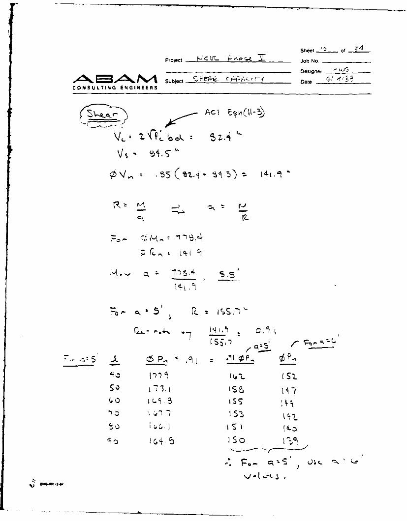
eCL 4 ~f~%(L%' C(vS z s')
M Pa. I: -77~, Ica. 4A ~
GS S (vA5 47.5
40 5 S 111.et 1'7,
ZO 0 , 70 C). CF~c
-P, Qc, .. ,k~ 6 4~~£1'~~ -
CI Vct'~eA, 4-0Z ~
67
C 7 Z OO
Sheet ot -
Prbject Job No.
Designer
XANo. Subject T,~ Date /CONSULTING ENGINEERS
' E~iG4P,o,4P
Sheet i1 of
Project c- ,.ob .No.
Designer v i
4 4AN~'%A SubjeCt 6 Pt-4 Date_____CONSULTING ENGINEERS
1 '
Q- --- _
!
S.-,5 Ac- Vo 'ci - 4.----+-,t
L o,6

Shoot __,_ of
Project Job No . .W sDesigner
Subject 24 Date _ _ _ _
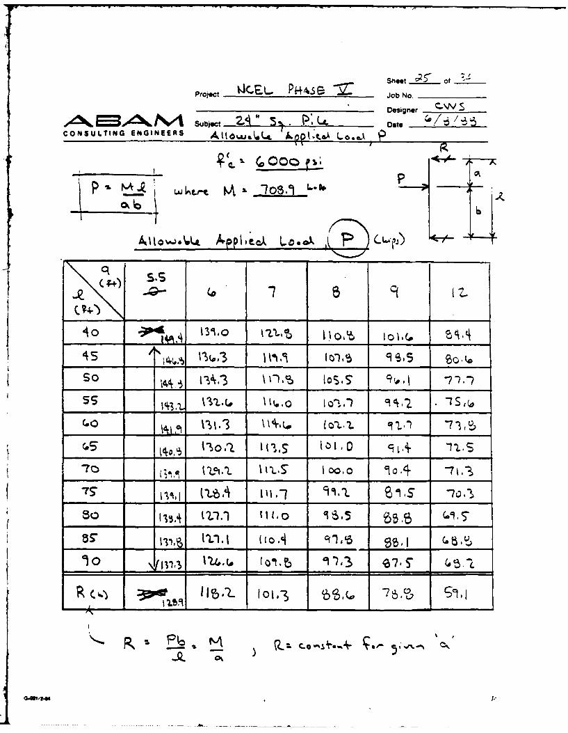
CONSULTING ENGINEERS At LoasAL P-.-8ooo ,," ..--- 7
P' Mlstp4Lo7lsAKL.O-
N Lo IS .o
40 51,0 1_-_____ __ _ _ _ _ _ __ 3,45 / 175,1 11. -7o. 7 7 9 .I"o ,
So 91.3 74, I l c~z.3
55 z1.2 9S.I _71,1 (0111 57.
(0 (5 1 92.0 (.-7,5_ _ _ _
"70 10.5 ,O,, 54.s
$17 i&5. __ _ C-1-0 50.9
'1o I5.4.5 o , ,.3 50,0
R R> I _P .
F6 0
Sheet " of
Project, ____.__.. P ,.e Job No.
Designer
,0 Subject __ __ __ __ __ __U_ Date ____ -____3
CONSULTING ENGINEERS AII ,J .L *. . p
'6
qL
45.4 0 " , 1 .. .. ' , i , II .(,, 9 ,-)__ __ __ _ c,,' I _______,' _ 1__-____,___,__ .
So (S1.o t__. _ _,____ I:S." ,"
M, -7
50
10~~j* 131." 3 1 0
____-___ - _______ 'U iih ___ __ _______
(I \JS 0 '6. _ _ _ _ _ _ _ 7.) _ _ _
P,.

Shot ~of 3Project .J CPIL- Pk+iE~ Job No.____
~, F.LLDesigner c.~Ws
CONSULTING ENGINEERS Alow Date _________P
P. _ L&JL,~ 6L@. 'Li
oh:, 6
C+ to 5 5 210 z.
4S 14. _ _ _ _ 19 __ _ _
so I (,u.3 7.( 113sel
*z el0 1c33 (-3__ 5 s(..i
170S e,.4 (P.4 51.0 4f
159,-1 ____t _ c' . ' .4 t __ __
10 159.1 s_ __ ___-__ 45.1i 415
K. R P6~

Sheet _
of _ 3_
Project %J'.~.,L r~44S ~Job No._ _ _ _ _ _
Designer
CONSULTING ENGINEERS
(. ~ 1 , tA5. Ii4,I LP ,o P', ?,
J;L oL
6
_____ ISI-SZ.S9.
s5 get, -7 -~ t1 , 7.
-75__ 1i , V). 9 104
lo4.o 91r
Projct IJC.A...P~A~. ~Shot 94 Of "Sb'roject Job o.
Designer
Ad6,E53Ak t" Sujc "& Date /e 83.,it CONSULTING ENGIEERS llo. L I,, -t,, &, .A ,,
0 t o IS 21o .5
4 'o k i.,Z.o ?1-5 "S.to -1o.9 ___5 __
45 15ct' 51m I 70.1 _._,_ _.
So 15-.5 690 , (" .5I _.,_1
- -5S 151,.o 95 (0,0 r5.") SZ.o
".0 tsIS." 5z.1i 4 o, S3.,2, _ _-,I
coo 53.1
I is 1519 __o,_ _____. 4b.S80 7 1.I 1 %1.0 St. ," 4 , 41..
<>0 (So.00 ___ _1 413 3_.1_ 'L5.4
-cxI
Sheet _ __ of ____
Project C. P .s - Job No.
Designer . SE ok Subject LL Date ~ "
CONSULTING ENGINEERS
S ""
"/o l , IL .ot %S Ipoft =to.L , __-- ___, _
45 11,, SO___ ~ .So I t .-3 l- ,os's
(.0 1', I%,tdcf ', ,I )u7o- ___. __ .- o 0. . ,
S -1 -1
- -(I. I__0_ _lw,-76 L2 S

Sheet ______ of LProject AsJob No.________
Designer .W .
, PM NA Subject 2A U L Date 1__6____
CONSULTING ENGINEERS i[ .L., L 8..-- P
45Co
ss
7o
75-so
no"
ENGoVZk
L': L
It 0
4~It-I'
-a ' -~.s - ------ ------ ---- A
- ,T - ~ - -- A - - -
Sheet- ______ of
Project Job No._______
Designer
,,dk% IM~e, N Subject DateCONSULTING ENGINEERS
c.~4L- ~U c~4 a ~r. .? *a• ./,_ .- C
-7 -7 8 .4t4 I-
-26
.. I I rneA

PROJECT: NCEL FENDER SYSTEM STUDY W/ 24" PILESDATE: 6/8/88DESIGNER: CWSPROGRAM: 'FENDER' DEVELOPED BY ABAM ENGR. INC.
DATA FILE: B:24STIFF.DATPILE NUMBER: 240 SQ. W/ RECT. STRAND PAT. &F c --aREVISION #: 0REMARKS: 28 STRANDS W/ 8/6/0 PAT.
PILE DIMENSIONS: .LENGTH .65 -f t -
LOAD FROM TOP 15 ftDEPTH - 24 inWIDTH - 24 in
CONCRETE DATA:STRENGTH f'c 8 ksiMODULUS E 4577 ksiPRESTRESS fpc = 1145 psi
STRAND DATA:STRAND TYPE = LOW RELAXATION# STRANDS = 28STRESS fpu = 270 ksiSTRESS fse = 154 ksiMODULUS E = 28000 ksiAREA - 1.224 sq.in DEPTH = 2.75 inAREA = .918 sq.in DEPTH = 4.75 inAREA - 0 sq.in DEPTH - 6.75 inAREA - 0 sq.in DEPTH = 17.25 inAREA - .918 sq.in DEPTH - 19.25 inAREA - 1.224 sq.in DEPTH 21.25 in
MQMENT Mn CURVATURE CONC STRAIN UPPER STRAND LOWER STRA ND NA DEPTH(k-ft) (rad/in) (in/in) STRESS (ksi) STRESS (ksi) (in)
234.8 2.085E-05 0.00050 -148.6 -159.4 24.00374.4 4 - - 0.00070 -144.5 -165.5 17.27466.3 6.57SE-05 0.00090 -140.9 -174.9 13.68541.3 9.559E-05 0.00110 -137.6 -187.1 11.51610.3 1.290E-04 0.00130 -134.5 -201.4 10.08676.5 1.654E-04 0.00150 -131.7 -216.9 9.07725.5 2.032E-04 0.00170 -129.1 -227.9 8.36Z2.415E-04 0.00190 -126.4 -235.2 7.q7778.4 2.803E-04 CO.00210j -123.8 -240.4 -4-794 3.194E-04 0.00230 -121.2 -244.3 7.20806.2 3.58SE-04 0.00250 -118.6 -247.4 6.97815.7 3.986E-04 0.00270 -116.1 -249.8 6.77823.4 4.387E-04 0.00290 -113.6 -251.7 6.61826jS 4.589E-04 0.00300 -112.3 -252.6 6.54

r-
*DATA FILE: B:24STIFF.DAT*PILE NUM13ER: 24" SQ. W/ RECT. S7RAND PAT. & 4'c =8
* REVISION #: 0REMARKS: 28 STRANDS W/ 8/6/0,PAT.
MOMENT Mn CONC STRAIN ENERGY LOAD DEFLECTION(k-ft) (in/in) (k-ft) (kips) (in)
234.8 0.00050 0.6 20.3 0.8374.4 0.00070 2.0 32.5 1.4466.3 0.00090 3.7 40.4 1.9541.3 0.00110 6.1 46.9 2.6610.3 0.00130 9.2 52.9 3.3676.5 0.00150 13.3 58.6 4.2725.5 0.00170 17.1 62.9 5.0756.8 0.00190 20.2 w')5.
806.2 0.00250 27.2 69.9 6.8815.7 0.00270 29.0 '70.7 7.1823.4 0.00290 30.7 71.4 7.4
8268 '.f0~fl31.5 71.7 7.5

- -' /z
PROJECT: NCEL FENDER SYSTEM STUDY W/: 24" PILESDATE: 6/8/88
DESIGNER: CWSPROGRAM: 'FENDER' DEVELOPED BY ABAM ENGR. INC.
DATA FILE: B:24STIFF.DAT --. ...PILE NUMBER: 240 SO. W/ RECT. STRAND PAT. &Vc 17!REVISION #: 0REMARKS: 28 STRANDS W/ 8/6/0 PAT.
PILE DIMENSIONS: "LENGTH 'm65 ftLOAD FROM TOP :1 15 ft ck_DEPTH -24 inWIDTH - 24 in
CONCRETE DATA:STRENGTH f'c - 7 ksiMODULUS E = 4346 ksiPRESTRESS fpc - 1145 psi
STRAND DATA:STRAND TYPE - LOW RELAXATION# STRANDS = 28STRESS fpu = 270 ksiSTRESS fse = 154 ksiMODULUS E = 28000 ksiAREA - 1.224 sq.in DEPTH = 2.75 inAREA - .918 sq.in DEPTH = 4.75 inAREA - 0 sq.in DEPTH = 6.75 inAREA - 0 sq.in DEPTH = 17.25 inAREA - .918 sq.in DEPTH = 19.25 inAREA - 1.224 sq.in DEPTH = 21.25 in
MOMENT Mn CURVATURE CONC STRAIN UPPER STRAND LOWER STRAND NA DEPTH(k-ft) (rad/in) (in/in) STRESS (ksi) STRESS (ksi) (in)
235.6 2.196E-05 0.00053 -148.3 -159.7 24.00356.1 3.856E-05 0.00070 -144.7 -164.7 18.16449.9 6.272E-05 0.00090 -141.0 -173.5 14.35525.0 9.135E-05 0.00110 -137.6 -184.9 12.04593.1 1.236E-04 0.00130 -134.5 -198.5 10.52654.5 1.577E-04 0.00150 -131.5 -213.2 9.51698.0 1.913E-04 0.00170 -128.5 -224.1 8.89727.5 2.252E-04 0.00190 -125.5 8-23 844
2.596E-04 (0.002101 -122.6 -237.0) 8.09764.3 2.943E-04 0.00230 -119.6 -241.2 7.81776.6 3.294E-04 0.00250 -116.7 -244.5 7.59786.5 3.649E-04 0.00270 -113.9 -247.1 7.40794.7 4.008E-04 0.00290 -111.0 -249.3 7.24798.3 4.188E-04 0.00300 -109.6 -250.2 7.16

* DATA FILE: B:24STIFF.DAT
* PILE NUMBER: 240 SO. W/ RECT. STRAND PAT. & f'c = 7* REVISION #. 0
REMARKS: 28 STRANDS W/ 8/6/0 PAT.
MOMENT Mn CONC STRAIN ENERGY LOAD DEFLECTI ON(k-Ift) (in/in) (k-+t) (kips) (in)
235.6 0.00053 0.7 20.4 0.8356.1 0.00070 1.8 30.9 1.3449.9 0.00090 3.4 39.0 1.9525.0 0.00110 5.6 45.5 2.5593.1 0.00130 8.6 51.4 3.2654.5 0.00150 12.2 56.7 4.0698.0 0.00170 15.4 60.5 4.7
zz-5 001018.1 AaL5.2( .o0210) 20.4 (64.99 5.6
764.3 0.00230 22.5 66.2 6.0776.6 (.00250 24.4 67.3 6.4786.5 0.00270 26.2 68.2 6.7794.7 0.00290 27.8 68.9 7.0798.3 0.00300 28.6 69.2 7.1
1PI

PROJECT: NCEL FENDER SYSTEM STUDY W/ 24" PILESDATE: 6/8/88
DESIGNER: CWSPROGRAM: 'FENDER" DEVELOPED 9Y ABAM ENGR. INC.
DATA FILE: B:24STIFF.DATPILE NUMBER: 240 SQ. W/ RECT. STRAND PAT. " =REVISION #: 0REMARKS: 28 STRANDS W/ 8/6/0 PAT.
PILE DIMENSIONS:LENGTH -l65 ft t.LOAD FROM TOP - 15 ft ---DEPTH IWIDTH = 24 in
CONCRETE DATA:STRENGTH f'c - 6 ksiMODULUS E = 4098 IsiPRESTRESS fpc = 1145 psi
STRAND DATA:STRAND TYPE = LOW RELAXATION# STRANDS = 28STRESS fpu = 270 ksiSTRESS fse - 154 ksiMODULUS E = 28000 ksiAREA = 1.224 sq.in DEPTH = 2.75 inAREA - .918 sq.in DEPTH = 4.75 inAREA - 0 sq.in DEPTH = 6.75 inAREA - 0 sq.in DEPTH = 17.25 inAREA - .918 sq.in DEPTH = 19.25 inAREA - 1.224 sq.in DEPTH = 21.25 in
MOMENT Mn CURVATURE CONC STRAIN UPPER STRAND LOWER STRAND NA DEPTH(k-ft) (rad/in) (in/in) STRESS (ksi) STRESS (ksi) (in)
236.5 2.329E-05 0.00056 -148.0 -160.0 24.00334.4 3.642E-05 0.00070 -145.0 -163.9 19.22430.8 5.939E-05 0.00090 -141.2 -172.0 15.16506.3 8.673E-05 0.00110 -137.7 -182.6 12.68572.7 1.174E-04 0.00130 -134.5 -195.3 11.07622.3 1.479E-04 0.00150 -131.2 -207.8 10.14660.1 1.774E-04 0.00170 -127.9 -218.7 9.58
2.070E-04 0 -124.6 7 9.18
S708,9 2,369E-04 - 0.00210 -!21.3 8.87-725.0 2.672E-04 0.00230 -118.0 -236.8 8.61737.8 2.979E-04 0.00250 -114.8 -240.5 8.39748.4 3.289E-04 0.00270 -111.6 -243.4 8.21757.4 3.604E-04 0.00290 -108.4 -245.9 8.05761.3 3.762E-04 0.003r0 -106.8 -246.9 7.97
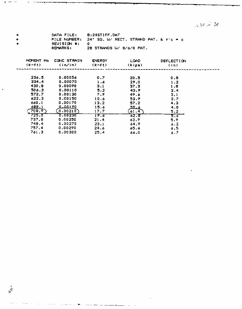
* DATA FILE: B:24STIFF.DAT* PILE NUMBER: 24" SO. W/ RECT. STRAND PAT. & f'c = 6* REVISION #: 0
REMARKS: 28 STRANDS W/ 8/6/0 PAT.
MOMENT Mn CONC STRAIN ENERGY LOAD DEFLECTION(k-ft) (in/in) (k-ft) (kips) (in)
---------------------------------------------------------------------------------------
236.5 0.00056 0.7 20.5 0.8334.4 0.00070 1.6 29.0 1.2430.8 0.00090 3.1 37.3 1.8506.3 0.00110 5.2 43.9 2.4572.7 0.00130 7.9 49.6 3.1622.3 0.00150 10.6 53.9 3.7660.1 0.00170 13.2 57.2 4.3688.1 n ng 15.6 59 4.8
,789) 0L 17.7 .614)5.2725.0 0.00230 19.6 62.8 .
737.8 0.00250 21.4 63.9 5.9748.4 0.00270 23.1 64.9 6.2757.4 0.00290 24.6 65.6 6.5761.3 0.00300 25.4 66.0 6.7

DISTRIBUTION LIST
DTIC Alexandria. VAGIDEP OIC. Corona. CANAS Code 110. Adak. AK: PW Engrg (Branson). Patuxent Riv~er. MD: SCE. Alameda. CANAVFACENGCOM Code 03. Alexandria. VA: Code 04. Alexandria. VA: Code 04A3. Alexandria. VA: Code
10. Alexandria. VANAVFACENGCOM -CHES DIV. FPO.IPL. Washington. DCNANFACENGCOM -LANT DIV'. Code 04. Norfolk. VA: librarv. Norfolk. VA
phNAVFACENGCOM - NORTH DIV. Code 04. Philadelphia. PA: Code O4AL, Philadelphia. PA: Code 408AF.Plsiladelphihia. PA
NAVFACENGCOM .PAC DIV. Code 04. Pearl Harbor. HI: LUbrarv. Pearl Harbor. INAVFACENGCOM -SOUTH DIN". Code 04. Charleston. SC: Librar%. Charleston. SCNANFACENGCONI WEST DIV. Code 04. San Bruno. CA: Code Ill. San Bruno. CA, Code 402. San Bruno.
CA: Code 04AZ22 (Libl. San Bruno. CANAVPHIBASE Code 432 (Turner). Norfolk. VANAVSTA SCE. Charleston. SC: SCE. Guam. Marianas Islands: SCE. Norfolk. VA: SCE. Pearl Harbor. HI.
SCE. San Diego. CANAVEASE Fac Plne & Proa. San Francisco. CANMCB 133. H-CO S311 (Engrg Dept)PWC CO. Guam. Maniana Islands: CO. Norfolk. VA: CO. Oakland. CA: CO. Pearl Harbor. HI. Code IM1
(Librar'(. Oakland. CA. Code 110. San Diego. CA: Code 123-C. San Diego. CA: Code 4tO0. Oakland. CA.Code 420. Great Lakes. IL: Code 7(X). Great Lakes. IL:- Librar% (Code 13!0. Pearl Harbor. HI: Librar%.Guam. Mariana Islands. Librar'. Norfolk. VA: Librarm. Pensacola. FL: Librarx. Yokosuka. Japan. Code421. Pearl Harbor. HI: Tech Librar%. Subic B3a%. RP
FLORIDA INST OF TECH G. Swain. M elbournec. FLSEATTLE UNIV'ERSITY CE Dept lSchwaeeler). Seattle. WATEXAS A&M UNIVERSITY CE Dept IMachemehll. College Station. TXALVIN ZANE & ASSOC. INC Honolulu. HlCOLLINS ENGRG. INC MI Garlich. Chicago. ILCURTIS ENGRG CORP DH Curtis. National Cit\. CAGEOTECHNICAL ENORS. INC Murdock. Winchester. MAINTL MARITIME. INC D Walsh. San Pedro. CALEO A DALY CO Honolulu. HIMC CLELLAND ENGRS. INC Librar',. Houston. TXMOFFATT & NICHOL ENGRS WS Shipple. Long Beach. CAPACIFIC MARINE TECH IM. Wagneti Duvall. WkAPRESNELL ASSOC. INC DG Presnell. Jr. Louisville. KYSTAN'S RAND Grizmala. Ogiden. UT