Pressurization System Modeling for a Generic Bimese Two ...€¦ · determines the tank...
8
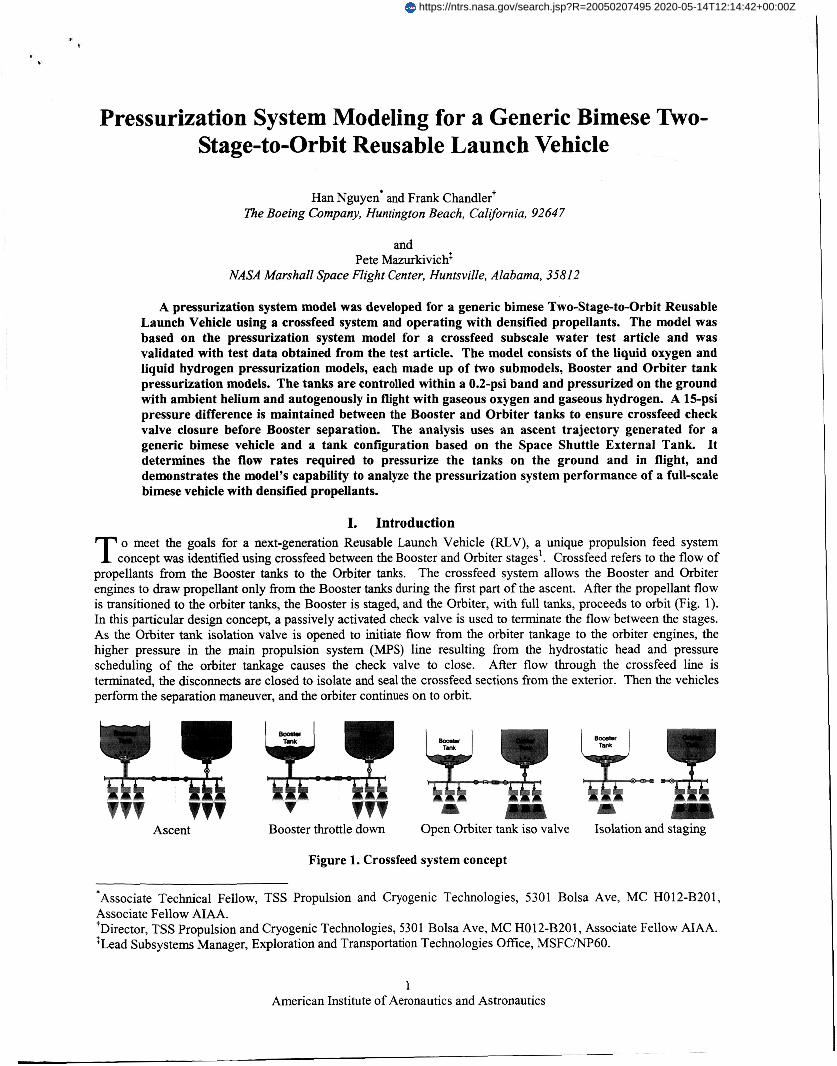
Pressurization System Modeling for a Generic Bimese Two- Stage-to-Orbit Reusable Launch Vehicle Han Nguyen. and Frank Chandlert The Boeing Company, Huntington Beach, California, 92647 and Pete Mazurkivich: NASA Marshall Space Flight Center, Huntsville, Alabama, 358 I2 A pressurization system model was developed for a generic bimese Two-Stagetoarbit Reusable Launch Vehicle using a crossfeed system and operating with densified propellants. The model was based on the pressurization system model for a crossfeed subscale water test article and was validated with test data obtained from the test article. The model consists of the liquid oxygen and liquid hydrogen pressurization models, each made up of two submodels, Booster and Orbiter tank pressurization models. The tanks are controlled within a 0.2-psi band and pressurized on the ground with ambient helium and autogenously in flight with gaseous oxygen and gaseous hydrogen. A 15-psi pressure difference is maintained between the Booster and Orbiter tanks to ensure crossfeed check valve closure before Booster separation. The analysis uses an ascent trajectory generated for a generic bimese vehicle and a tank configuration based on the Space Shuttle External Tank. It determines the flow rates required to pressurize the tanks on the ground and in flight, and demonstrates the model's capability to analyze the pressurization system performance of a full-scale bimese vehicle with densified propellants. I. Introduction o meet the goals for a next-generation Reusable Launch Vehicle (IUV), a unique propulsion feed system T concept was identified using crossfeed between the Booster and Orbiter stages'. Crossfeed refers to the flow of propellants fiom the Booster tanks to the Orbiter tanks. The crossfeed system allows the Booster and Orbiter engines to draw propellant only from the Booster tanks during the first part of the ascent. After the propellant flow is transitioned to the orbiter tanks, the Booster is staged, and the Orbiter, with full tanks, proceeds to orbit (Fig. 1). In this particular design concept, a passively activated check valve is used to terminate the flow between the stages. As the Orbiter tank isolation valve is opened to initiate flow from the orbiter tankage to the orbiter engines, the higher pressure in the main propulsion system (MPS) line resulting from the hydrostatic head and pressure scheduling of the orbiter tankage causes the check valve to close. After flow through the crossfeed line is terminated, the disconnects are closed to isolate and seal the crossfeed sections from the exterior. Then the vehicles perform the separation maneuver, and the orbiter continues on to orbit. Ascent Booster throttle down Open Orbiter tank is0 valve Isolation and staging Figure 1. Crossfeed system concept *Associate Technical Fellow, TSS Propulsion and Cryogenic Technologies, 5301 Bolsa Ave, MC H012-B201, Associate Fellow AIAA. Director, TSS Propulsion and Cryogenic Technologies, 5301 Bolsa Ave, MC HO12-B201, Associate Fellow A I M . :Lead Subsystems Manager, Exploration and TransportationTechnologies Office, MSFC/NP60. t 1 American Institute of Aeronautics and Astronautics https://ntrs.nasa.gov/search.jsp?R=20050207495 2020-05-14T12:14:42+00:00Z
Transcript of Pressurization System Modeling for a Generic Bimese Two ...€¦ · determines the tank...
Pressurization System Modeling for a Generic Bimese Two- Stage-to-Orbit Reusable Launch Vehicle
Han Nguyen. and Frank Chandlert The Boeing Company, Huntington Beach, California, 92647
and Pete Mazurkivich:
NASA Marshall Space Flight Center, Huntsville, Alabama, 358 I2
A pressurization system model was developed for a generic bimese Two-Stagetoarbit Reusable Launch Vehicle using a crossfeed system and operating with densified propellants. The model was based on the pressurization system model for a crossfeed subscale water test article and was validated with test data obtained from the test article. The model consists of the liquid oxygen and liquid hydrogen pressurization models, each made up of two submodels, Booster and Orbiter tank pressurization models. The tanks are controlled within a 0.2-psi band and pressurized on the ground with ambient helium and autogenously in flight with gaseous oxygen and gaseous hydrogen. A 15-psi pressure difference is maintained between the Booster and Orbiter tanks to ensure crossfeed check valve closure before Booster separation. The analysis uses an ascent trajectory generated for a generic bimese vehicle and a tank configuration based on the Space Shuttle External Tank. It determines the flow rates required to pressurize the tanks on the ground and in flight, and demonstrates the model's capability to analyze the pressurization system performance of a full-scale bimese vehicle with densified propellants.
I. Introduction o meet the goals for a next-generation Reusable Launch Vehicle (IUV), a unique propulsion feed system T concept was identified using crossfeed between the Booster and Orbiter stages'. Crossfeed refers to the flow of
propellants fiom the Booster tanks to the Orbiter tanks. The crossfeed system allows the Booster and Orbiter engines to draw propellant only from the Booster tanks during the first part of the ascent. After the propellant flow is transitioned to the orbiter tanks, the Booster is staged, and the Orbiter, with full tanks, proceeds to orbit (Fig. 1). In th is particular design concept, a passively activated check valve is used to terminate the flow between the stages. As the Orbiter tank isolation valve is opened to initiate flow from the orbiter tankage to the orbiter engines, the higher pressure in the main propulsion system (MPS) line resulting from the hydrostatic head and pressure scheduling of the orbiter tankage causes the check valve to close. After flow through the crossfeed line is terminated, the disconnects are closed to isolate and seal the crossfeed sections from the exterior. Then the vehicles perform the separation maneuver, and the orbiter continues on to orbit.
Ascent Booster throttle down Open Orbiter tank is0 valve Isolation and staging
Figure 1. Crossfeed system concept
*Associate Technical Fellow, TSS Propulsion and Cryogenic Technologies, 5301 Bolsa Ave, MC H012-B201, Associate Fellow AIAA. Director, TSS Propulsion and Cryogenic Technologies, 5301 Bolsa Ave, MC HO12-B201, Associate Fellow A I M .
:Lead Subsystems Manager, Exploration and Transportation Technologies Office, MSFC/NP60.
t
1 American Institute of Aeronautics and Astronautics
https://ntrs.nasa.gov/search.jsp?R=20050207495 2020-05-14T12:14:42+00:00Z

As part of the Space Launch Initiative (SLI) TA-8 MPS Crossfeed Demonstration p r~ jece ’~ , a model was developed to analyze transient flow in the crossfeed system. The model consisted of a pressurization system model and a crossfeed system model. A subscaled water flow test article was also designed and built to demonstrate the crossfeed concept. This test article provided test data that were correlated to the pressurization and crossfeed system models. As the goal of the crossfeed system is to reduce the weight and Design, Development, Test, and Evaluation (DDT&E) of a Two-Stage-to-Orbit (TSTO) Reusable Launch Vehicle (RLV) while increasing its safety and reliability, the pressurization system performance of a full-scale bimese TSTO RLV was modeled using the validated pressurization system model of the water flow test article. This paper presents the approach and results of this modeling.
II. Modeling Approach A pressurization system model consisting of a tank thermodynamic model and a pressurization line model was
developed for the crossfeed subscale water flow test article in Huntington Beach, California. This model was used to predict the performance of the pressurization system for the test article. Following the completion of the subscale water flow tests, the model was correlated to the test data. The validated model was then updated to a full-scale generic bimese vehicle with cryogenic propellants.
E
/ T w t
Figure 2. Schematic of tank thermodynamic model
The tank thermodynamic model is a lumped parameter model that consists of four nodes: ullage, liquid, tank wall facing ullage, and tank wall facing liquid (Fig. 2). The tank wall is split into two nodes because of the large temperature difference between the two wall sections and the resulting heat conduction across their interface. Although thermal stratification exists in these nodes, the model assumes uniform temperatures in the ullage and liquid. The pressurization system model determines the thermodynamic properties (pressure, temperature, volume, and mass) of the nodes as a function of time from start of ground prepress to main engine cutoff (MECO). These properties are governed by the conservations of mass and energy, the equation of state, and the thermophysical properties of the f l ~ i d s ~ , ~ , ~ .
The pressurization system models were developed using EASY5 PC-Win32 and the General Purpose Library. EASY5 is a software;
used to model, analyze, and design dynamic systems characterized by differential, ‘and: difference, and algebraic equations’. EASY5 models can be assembled in two ways: (1) using primitive functional blocks, such as summers, dividers, and integrators, from the General Purpose library, or (2) using application-specific components from the gas dynamics, basic hydraulic, thermal-hydraulic, multiphase fluid libraries, etc. The pressurization system models for the TSTO FUV were based on the flight-verified models of the Space Shuttle and Delta IV. To take full advantage of the knowledge and experience gained in modeling the Shuttle and Delta IV pressurization systems, the TSTO RLV’s models were developed from the basic governing equations using the General Purpose Library.
The pressurization system models for the bimese TSTO RLV consists of the LO2 tank and LHz tank pressurization models. Each model is made up of a Booster submodel and an Orbiter submodel. A representative EASY5 block diagram is shown in Fig. 3 for the liquid oxygen (LOz) Booster tank model. The diagrams for the LOz Orbiter, liquid hydrogen (LHJ Booster, and LHz Orbiter tank models are identical to that of the LOz Booster tank, except for their input data, which are specific to the types of propellants and vehcle stages.
2 American Institute of Aeronautics and Astronautics
r

In addition to the primitive functional blocks, a number of Fortran components were created to calculate the ullage pressure, time rate of change of ullage temperature, and heat-transfer rates between the ullage, liquid, and tank wall. These Fortran components were used in a Fortran model developed in parallel with the EASY5 model to check out the EASY5 pressurization system models.
The thermophysical properties of the propellants (oxygen and hydrogen) and prepress gas (helium) are obtained from the database of the National Institute of Standards and
They are entered in the Fortran components and determined by table lookup using one- and two-variable interpolation subroutines.
Initiation and termination of ground prepress are achieved by using a square wave generator.
The square wave output signal, which represents the prepress flow rate, is set to a poskve value from the start of prepress to T-0 and to zero thereafter. Initiation of in-flight pressurization is achieved by using a step function generator. The step function output signal, which represents the pressurization flow rate, is equal to zero fiom the start of prepress to engine start and to a positive value thereafter. For both ground prepress and in-flight pressurization, ullage pressure control is achieved by using a deadband controller. The controller output is positive when the ullage pressure falls to the minimum pressure and is zero when the ullage pressure reaches the maximum pressure of the control band.
A number of tabular functions are used to provide various inputs to the model. The propellant density and specific heats and the tank wall specific heat are given as a function of temperature in single-column one- dimensional tables. The ascent trajectory, tanking tables, and liquid properties are provided in multicolumn one- dimensional tables. In the ascent trajectory, the LOz and LHz flow rates from the Booster and Orbiter tanks, vehicle axial acceleration, and ambient pressure are given as a function of time. In the tanking tables, the liquid height, liquid surface radius, wall area, and wall mass are provided as a function of liquid volume.
III. Analysis Conditions A pressurization system analysis was performed for the full-scale generic bimese vehicle. The analysis is
divided into two parts: (1) LOz Booster and Orbiter tanks; and (2) LHz Booster and Orbiter tanks. The analysis determines the tank thermodynamic conditions fiom start of ground prepress to Orbiter MECO. Since the Booster tank is staged after crossfeed flow termination, the analysis ends at staging for the Booster tank, but continues to MECO for the Orbiter tank.
The tanks are pressurized on the ground with ambient gaseous helium (GHe). In flight, the LOz tanks are autogenously pressurized with gaseous oxygen (GOZ) and the LH2 tanks with gaseous hydrogen (GH,). For both ground prepress and in-flight pressurization, the ullage pressure is maintained within a 0.2-psi control band. To satisfy the Booster engine inlet pressures, the Booster ullage pressures are set at
LO2 Booster ullage: 2 1 f 0.1 psig
LHz Booster ullage: 36 f 0.1 psig
To ensure crossfeed check valve closure when the Orbiter isolation valve opens, a 15-psi pressure difference is maintained between the Booster and Orbiter tanks. As a result, the set points of the Orbiter ullage pressures are
LO2 Orbiter ullage: 36 f 0.1 psig
LHz Orbiter ullage: 5 1 f 0.1 psig
3 Amencan Institute of Aeronautics and Astronautics

The analysis considers the case where one Orbiter engine is out, so that all five Booster but only four Orbiter engines are operating at liftoff. It is based on an operation sequence that consists of a 6-second staggered start transient, Orbiter engine throttling, Booster engine throttle down before crossfeed termination and shutdown after Booster staging, and Orbiter engine shutdown. The main events of this sequence are summarized in Table 1.
/
Table 1. Operation sequence of TSTO RLV
Time, Seconds Event Description
-6.000-0.000 Engine start 0.000 Liftoff 46.000-62.000 Orbiter engine throttling 92.000-97.000 Booster engine throttle down 97.200- 100.600 Booster engine shutdown 105.000-1 10.000 113.000-1 16.000 Disconnect valve closing 1 16.100-1 17.100 BoostedOrbiter separation 118.000-120.000 123 .OOO- 126.000 345.000-353.800
Orbiter isolation valve opening
Orbiter engine mixture ratio change Booster engine shutdownhegin glide back Orbiter engine shutdownhegin low-g coast
At the start of ground prepress, the tank conditions are given by Table 2:
Table 2. Initial tank conditions
Conditions LO2 Percent ullage 5 5 Ullage pressure, psig 0.2 0.2 Ullage temperature, R 163 37
Wall temperature (facing ullage), R 163 37 Liquid temperature, R 125 30
Wall temperature (facing liquid), R 125 30
The timeline for tank pressurization is defined as follows:
Booster and Orbiter prepress Booster pressurization Orbiter pressurization
from T-120 s to T-0 s (liftoff) from T-6 s to T+126 s (Booster MECO) from T-6 s to T+353.8 s (Orbiter MECO)
IV. Results and Discussions Using the conditions established in Section IV, the pressurization system model determines the thermodynamic
conditions in the Booster and Orbiter propellant tanks from the start of prepress to Orbiter MECO. The ullage pressure, sump pressure, and ullage mass were plotted in Figs. 4 through 9 for the LOz and LH2 Booster tanks, and Figs. 10 through 15 for the LO2 and LHz Orbiter tanks.
On the ground, the LO2 tanks are pressurized with 1 lbds and the LH2 tanks with 2 lbds of GHe. The GHe consumption during prepress totals 21 lb, for the LO2 Booster tank, 53 lb, for the LH2 Booster tank, 30 lb, for the LOz Orbiter tank, and 69 lb, for the LH2 Orbiter tank.
As mentioned in section 111, the LO2 tanks are autogenously pressurized in flight with GOz and the LHz tanks with GH2. On the Booster side, the LO2 tank is pressurized with 26.1 1bJs and the LH2 tank with 4.5 lb&, resulting in an ullage mass residual of 2142 lb, in the LO2 tank and 667 lb, in the LH2 tank at staging. On the Orbiter side, the LO2 tank is pressurized with 14 1bJs and the LH2 tank with 3 lb,/s, amounting to 3 185 lb, in the LO2 tank and 858 lb, in the LH2 tank at Orbiter MECO.
4 American Institute of Aeronautics and Astronautics

LG-2BoosterTank
GW FTSWESJ Fbw Rae: 1 W s GO2 Press flaw Rae: 28.1 lbmls
LlllaDe cantrm Band:20.821.1 psQ
P
I 9
1 1
I I
j I 1 I I I I I I
18 -150 -100 40 50 100 150
TW Fmrn una , SWXUIS
LO2 BooJter Taw.
GH2 P w e s Fbw Rate 1 IbWs U l h e contml Band 20 821 1 psg
Figure 4. LO2 Booster ullage pressure
I I 1 I LHZBocsmTank Ullage COntml Band 35 036 I p 6 ~
I ~ GHePrepressFlowRak Zlbrms I 1 2 M O
Figure 5. LO2 Booster sump pressure
GHZRessFlovRQe 4 5 I M s
le00
E p u)
1 !j 1200
9 38
M
0
800 I 1 1 1 I ! 1
, I
I 01 I 1 ! -100 5 0 0 50 100 150
~une From LA-^, sgonds
i
Figure 7. LH2 Booster ullage pressure
5 American Institute of Aeronautics and Astronautics

Figure 8. LHz Booster sump pressure
700
mo
500 I f p 5 400
300
200 -1 50
Ullage Cow Band: 35.436.1 psig GH2 Repress F!-m Rate: 1 I W s GO2 Ress Fbw Rate 14 lbds 45
1
LHZBmsterTank UllageCormolBand 3 5 4 3 6 1 psg GHe R e p s b w Rate 2 lbmk
__ GHZReSSFbwRae 451bm/s
/
I
1 I
/ 4 1 I I
1 -1 00 -50 0 53 100 150
30
Figure 10. LOz Orbiter ullage pressure
Figure 9. LHz Booster ullage mass
UllageControlBad 359-361 pslg
GO2 Ress b Rate 14 Ibmk GH2 Prepress nau Pate 1 Ibm/s
-2 00 -1 00 0 100 200 3M 4cn Xme Fmm Lift-011. &&
Figure 11. LOz Orbiter sump pressure
6 American Institute of Aeronautics and Astronautics

3.5E+3
moo
z m
E 2000
1 8 ij 1500
lorn
5w
0
/
I I I LH2 abiter Tank Ullage Contml Band: 50.851.1 P J ~ GHe Prepress Flow Rde: 2 IMS 45 ~.
i i GHZ PES F ~ W w: 3 I b M
Figure 12. LOz Orbiter ullage mass
40 -200 -100 0 100 XI0 300 400
Time F m L M . Semnds
Figure 14. LHz Orbiter sump pressure
1wc
8oc
E a - f 2 m f 3
400
200 -200
Figure 13. LHz Orbiter ullage pressure
I I
LW OlbnerTank I Ullage Control Barn: 50.951.1 psb GHe Prepras Flow Rate: 2 I M GH2 Press Fbw Ri
I / I
I
-100 0 100 200 300 400 ~ i m e Fmm M-OR, ~emnds
Figure 15. LH2 Orbiter ullage mass
7 Amencan Institute of Aeronautics and Astronautics

The maximum tank pressures are obtained at the sumps where the pressure heads are largest. They are about 45 psig at the LO2 Booster sump, 39 psig at the LH2 Booster sump, 79 psig at the LOz Orbiter sump, and 65 psig at the LH2 Orbiter sump. They occur when the ullage gage pressures, liquid height, and vehicle acceleration combine to give the largest sump pressures: this happens around liftoff for the Booster tanks, and at about T+90 seconds for the Orbiter tanks.
From T-0 to the start of Orbiter tank outflow, the Orbiter ullage pressure rises by 5.8 psi in the LO2 tank and 9.5 psi in the LHz tank. The combined effects of a decreasing ambient pressure during ascent and a constant ullage volume prior to Orbiter tank outflow cause this pressure rise. The constant ullage volume maintains the ullage pressure in absolute pressure at the levels reached during prepress, even without flight pressurization. Once flows from the Orbiter tanks are initiated and the Orbiter ullage pressures start decaying, in-flight pressurization reestablishes ullage pressure control in the tanks.
V. Conclusions The pressurization system model developed using EASY5 for a generic bimese TSTO RLV was used to
determine the pressurization requirements for the LO2 Booster and Orbiter tanks and LH2 Booster and Orbiter tanks. Using a generic trajectory that provides ascent data from liftoff to Orbiter MECO, the model determine the GHe requirement for ground prepress and the GO2 and GH2 requirements for in-flight pressurization. It shows that the tanks can be adequately pressurized to meet engine inlet pressure requirements and crossfeed valve operating conditions. The model also demonstrates its capability to perform a pressurization system performance for a generic bimese vehicle with densified cryogenic propellants and can be used to design the pressurization systems of future bimese TSTO RLV’s.
Acknowledgments The work reported in this paper was performed under NASA Contract No. NAS8-01099, TA-8 M P S Crossfeed
Demonstration, for NASA Marshall Space Flight Center. Mr. Shayne Swint, Contracting Officer Technical Representative Designee; Dr. Tom Brown, Lead System Engineer; Mr. Pete Mazurkivich, Lead Subsystem Manager; and Mr. Chris Popp, Engineering Lead, provided the technical leadership at NASA. Dr. Frank Chandler, Principal Investigator, provided the leadership for the Boeing TA-8 technical team
References Chandler, F., Scheiern, M., Champion, R., and Mazurkivich, P., “Launch Vehicle Sizing Benefits Utilizing Main Propulsion
’Chandler, F., et. al., “TA-8 MPS Crossfeed Demonstration Final Report Through Option 1 Period,” PWDM03-0076, The
1
System Crossfeed and Project Status,” AIAA Paper 2002-3900, July 2002.
Boeing Company, 30 May 2003. ’Chandler, F., et. al., “TA-8 M P S Crossfeed Demonstration Summary Report,” PWDM03-0123, The Boeing Company, 30
May 2003. Ring, E., et. al., Rocket Propellant and Pressurization Systems, Prentice-Hall, Inc. Basic Pressurization Systems Design Guide, Volume I, System Analysis and Selection,” Aerojet-General Corporation,
6Lak, T., and Gerhardt, D. L., “Generic Fluid Transfer Model - Computer Model Description Document,” Rockwell
’Tollefson, J., EASY5 User’s Guide, The Boeing Company, September 1996. ‘McCarty, R. D., and Weber, L. A., “Thermophysical Properties of Parahydrogen From the Freezing Liquid Line to 5000 R
for Pressures to 10,000 psia,” NBS Technical Note 6 17, April 1972. QcCarty, R. D., and Weber, L. A., “Thermophysical Properties of Oxygen From the Freezing Liquid Line to 600 R for
Pressures to 5,000 psia,” NBS Technical Note 384, July 1971. Lemon, E W., Peskin, A. P., McLinden, M. O., and Friend, D. G., “NIST Thermodynamic and Transport Properties of
Pure Fluids - NIST Pure Fluids,” Version 5.0, Physical and Chemical Properties Division, National Institute of Standards and Technology, Sept. 2000.
-4
5
Report No. 2736, Dec. 1965.
International, Rept. DIU-9, Dec. 1987.
10
8 American Institute of Aeronautics and Astronautics