
Final year projects 2014 - 15 (IEEE & APPLICATION PROJECTS) @ HCL
Upload
miguel-saldivar-hernandezCategory
view
25download
0

Other Books on ASME Code from McGraw-Hill
ANTAKI ⋅ Fitness-for-Service Piping and Pressure Vessels: ASME Code Simplified
ELLENBERGER ⋅ Pressure Vessels: ASME Code Simplified, 8/e
ELLENBERGER ⋅ Piping Systems & Pipeline: ASME Code Simplified
MALEK ⋅ Power Boiler Design, Inspection, and Repair: ASME Code Simplified
WELSH ⋅ Elevator and Escalator: ASME Code Simplified
PressureRelief
DevicesASME and API Code Simplified
Mohammad A. Malek, Ph.D., P.E.
McGraw-HillNew York Chicago San Francisco Lisbon London Madrid
Mexico City Milan New Delhi San Juan Seoul Singapore Sydney Toronto
Copyright © 2006 by The McGraw-Hill Companies, Inc. All rights reserved. Manufactured in theUnited States of America. Except as permitted under the United States Copyright Act of 1976, no partof this publication may be reproduced or distributed in any form or by any means, or stored in a database or retrieval system, without the prior written permission of the publisher.
0-07-158906-6
The material in this eBook also appears in the print version of this title: 0-07-145537-X.
All trademarks are trademarks of their respective owners. Rather than put a trademark symbol afterevery occurrence of a trademarked name, we use names in an editorial fashion only, and to the benefit of the trademark owner, with no intention of infringement of the trademark. Where such designations appear in this book, they have been printed with initial caps.
McGraw-Hill eBooks are available at special quantity discounts to use as premiums and sales promotions, or for use in corporate training programs. For more information, please contact GeorgeHoare, Special Sales, at [email protected] or (212) 904-4069.
TERMS OF USE
This is a copyrighted work and The McGraw-Hill Companies, Inc. (“McGraw-Hill”) and its licensorsreserve all rights in and to the work. Use of this work is subject to these terms. Except as permittedunder the Copyright Act of 1976 and the right to store and retrieve one copy of the work, you may notdecompile, disassemble, reverse engineer, reproduce, modify, create derivative works based upon,transmit, distribute, disseminate, sell, publish or sublicense the work or any part of it withoutMcGraw-Hill’s prior consent. You may use the work for your own noncommercial and personal use;any other use of the work is strictly prohibited. Your right to use the work may be terminated if youfail to comply with these terms.
THE WORK IS PROVIDED “AS IS.” McGRAW-HILL AND ITS LICENSORS MAKE NO GUARANTEES OR WARRANTIES AS TO THE ACCURACY, ADEQUACY OR COMPLETENESS OFOR RESULTS TO BE OBTAINED FROM USING THE WORK, INCLUDING ANY INFORMATIONTHAT CAN BE ACCESSED THROUGH THE WORK VIA HYPERLINK OR OTHERWISE, ANDEXPRESSLY DISCLAIM ANY WARRANTY, EXPRESS OR IMPLIED, INCLUDING BUT NOT LIM-ITED TO IMPLIED WARRANTIES OF MERCHANTABILITY OR FITNESS FOR A PARTICULARPURPOSE. McGraw-Hill and its licensors do not warrant or guarantee that the functions contained in thework will meet your requirements or that its operation will be uninterrupted or error free. Neither McGraw-Hill nor its licensors shall be liable to you or anyone else for any inaccuracy, error or omission, regardless ofcause, in the work or for any damages resulting therefrom. McGraw-Hill has no responsibility for the con-tent of any information accessed through the work. Under no circumstances shall McGraw-Hill and/or itslicensors be liable for any indirect, incidental, special, punitive, consequential or similar damages that resultfrom the use of or inability to use the work, even if any of them has been advised of the possibility of suchdamages. This limitation of liability shall apply to any claim or cause whatsoever whether such claim or causearises in contract, tort or otherwise.
DOI: 10.1036/007145537X

We hope you enjoy thisMcGraw-Hill eBook! If
you’d like more information about this book,its author, or related books and websites,please click here.
Professional
Want to learn more?
Contents
Preface xv
Chapter 1. Fundamentals of Pressure Relief Devices 1
1.1 Brief History 11.2 Pressure Vessels 2
1.2.1 Boiler accidents 31.2.2 Pressure vessel accidents 5
1.3 Pressure Relief Devices 71.4 Reclosing-Type Pressure Relief Devices 8
1.4.1 Pressure relief valves 81.4.2 Safety valves 81.4.3 Relief valves 101.4.4 Safety relief valves 12
1.5 Pressure Vacuum Relief Valves 121.5.1 Pressure vacuum vent valves 131.5.2 Pressure relief valves 141.5.3 Vacuum relief valves 14
1.6 Nonreclosing Pressure Relief Devices 141.6.1 Rupture disks 151.6.2 Breaking pin devices 161.6.3 Buckling pin devices 171.6.4 Shear pin devices 171.6.5 Fusible plug devices 18
1.7 Codes and Standards 181.7.1 U.S. codes 181.7.2 International codes 19
1.8 Jurisdictional Authority 20
Chapter 2. Pressure Relief Valves 23
2.1 Safety Relief Valves 242.1.1 Conventional pressure relief valves 242.1.2 Pilot-operated pressure relief valves 292.1.3 Balanced bellows pressure relief valves 382.1.4 Power-actuated pressure relief valves 422.1.5 Temperature-actuated pressure relief valves 43
v
For more information about this title, click here
2.2 Relief Valves 442.3 Safety Valves 462.4 Major Components 472.5 Accessories 482.6 Specifications 51
2.6.1 How to order a conventional pressurerelief valve 51
2.6.2 Specification sheets 51
Chapter 3. Safety Valves 53
3.1 Working Principle 533.2 Classification of Safety Valves 56
3.2.1 Classification based on actuation 563.2.2 Classification based on lift 583.2.3 Classification based on seat design 593.2.4 Classification based on type of lever 593.2.5 Classification based on bonnet design 60
3.3 Major Components 613.4 Accessories 623.5 Safety Valve Locations 62
3.5.1 Pressure-reducing station 633.5.2 Pharmaceutical factory with jacketed pans 64
3.6 Specifications 653.6.1 Specification sheet 663.6.2 Specifying a safety valve 67
Chapter 4. Rupture Disks 69
4.1 Brief History 704.2 Working Principle 704.3 Application of Rupture Disks 71
4.3.1 Primary relief 724.3.2 Secondary relief 734.3.3 Combination relief 73
4.4 Types of Rupture Disks 744.4.1 Conventional rupture disks 744.4.2 Scored tension-loaded rupture disks 764.4.3 Composite rupture disks 764.4.4 Reverse-acting rupture disks 774.4.5 Graphite rupture disks 79
4.5 Major Components 804.6 Accessories 804.7 Specifications 83
4.7.1 How to specify a rupture disk 834.7.2 Specification sheet 83
4.8 Rupture Pin Relief Valves 834.8.1 Comparison of rupture pins and rupture disks 84
4.9 Buckling Pin Relief Valves 844.9.1 Valve characteristics 864.9.2 Specifications 87
vi Contents
Contents vii
Chapter 5. Materials 89
5.1 Pressure Relief Valves 895.1.1 Materials 905.1.2 Bill of materials 945.1.3 Material selection 96
5.2 Rupture Disks 1035.2.1 Bill of materials 1035.2.2 Material selection 103
Chapter 6. Design 109
6.1 Fundamentals of Design 1116.1.1 Seat disk lift 1116.1.2 Back pressure 1126.1.3 Bonnet 1146.1.4 Valve nozzle 115
6.2 Design Factors 1166.2.1 Flow area 1166.2.2 Curtain area 1176.2.3 Discharge area 1176.2.4 Other design factors 117
6.3 Pressure Requirements 1186.3.1 System pressures 1186.3.2 Relieving device pressures 120
6.4 Design Considerations 1206.5 Design of Parts 121
6.5.1 Body 1216.5.2 Bonnet 1216.5.3 Nozzle 1216.5.4 Disk 1226.5.5 Spindle 1226.5.6 Adjusting ring 1226.5.7 Adjusting screw 1226.5.8 Huddling chamber 1226.5.9 Spring 122
6.6 Testing and Marking 1226.6.1 Hydrostatic test 1236.6.2 Marking 123
6.7 Rupture Disks 1236.7.1 Basic design 1236.7.2 Operating ratios 1256.7.3 Pressure-level relationship 1256.7.4 Certified KR and MNFA 126
Chapter 7. Manufacturing 129
7.1 Manufacture of Pressure Relief Valves 1307.1.1 Test laboratories 1317.1.2 Capacity certification 1337.1.3 Capacity certification in combination with
rupture disks 1387.1.4 Testing by manufacturers 139
viii
7.1.5 Inspection and stamping 1407.1.6 Manufacturer’s data reports 141
7.2 Manufacture of Rupture Disks 1417.2.1 Manufacturing ranges 1447.2.2 Rupture tolerances 1447.2.3 Capacity certification 1457.2.4 Production testing 1467.2.5 Marking 1477.2.6 Manufacturer’s data reports 149
Chapter 8. Sizing and Selection 151
8.1 Pressure Relief Valves 1518.1.1 Valve sizes 1528.1.2 Required sizing data 1538.1.3 API sizing 1558.1.4 Sizing for vapors and gases 1568.1.5 Sizing for liquids 1638.1.6 Sizing for air 1678.1.7 Sizing multiple valves 1688.1.8 Saturated-water valve sizing 1708.1.9 RRV and rupture disk combinations 171
8.1.10 Sizing for thermal expansion of trapped liquids 1748.1.11 Sizing for mixed phases 175
8.2 Rupture Disks 1768.2.1 Sizing method 177
Chapter 9. Safety Valves for Power Boilers 179
9.1 Operational Characteristics 1829.2 Code References 1829.3 Design Requirements 182
9.3.1 Mechanical requirements 1839.3.2 Material selection 1849.3.3 Boiler safety valves 1849.3.4 Superheater safety valves 1869.3.5 Reheater safety valves 1899.3.6 Organic fluid vaporizer safety valves 189
9.4 Capacity Requirements 1899.4.1 Relieving capacity 1909.4.2 Capacity checking 1939.4.3 Capacity certification 195
9.5 Testing by Manufacturers 1999.6 Inspection and Stamping 1999.7 Certificate of Conformance 2009.8 Operation 2019.9 Selection of Safety Valves 201
9.9.1 Ordering information 2029.9.2 Specifying safety valves 202
Chapter 10. Pressure Relief Valves for Heating Boilers 205
10.1 Code References 20710.2 Design Requirements 207
viii Contents
ix
10.2.1 Safety valve requirements for steam boilers 20810.2.2 Safety relief valve requirements for hot
water boilers 21110.2.3 Safety and safety relief valves for tanks and
heat exchangers 21310.2.4 T&P safety relief valves for hot water heaters 21310.2.5 Mechanical requirements 21510.2.6 Material selection 21610.2.7 Locations 216
10.3 Manufacture and Inspection 21610.3.1 Valve markings 217
10.4 Manufacturer’s Testing 21810.5 Capacity Requirements 219
10.5.1 Calculation of capacity to be stamped on valves 21910.5.2 Fluid medium for tests 22210.5.3 Capacity tests of T&P safety relief valves 22210.5.4 Capacity tests for safety and safety relief valves 22210.5.5 Test record data sheets 223
Chapter 11. Pressure Relief Devices for Pressure Vessels 225
11.1 Introduction 22511.1.1 Types of pressure vessels 22711.1.2 Pressure vessel codes 22911.1.3 Pressure relief devices 231
11.2 Pressure Relief Valves 23111.2.1 Operational requirements 23311.2.2 Code references 23411.2.3 Design requirements 23411.2.4 Capacity certification 24211.2.5 Testing by manufacturers 24411.2.6 Inspection and certification 245
11.3 Rupture Disks 24711.3.1 Operational characteristics 24911.3.2 Code references 24911.3.3 Design requirements 24911.3.4 Capacity certification 25011.3.5 Testing by manufacturers 25111.3.6 Inspection and certification 252
Chapter 12. Pressure Relief Devices for Nuclear Systems 255
12.1 Nuclear Reactors 25612.1.1 Boiling-water reactors 25712.1.2 Pressurized-water reactors 259
12.2 Overpressure Protection Reports 26412.2.1 Content of report 26412.2.2 Certification of report 26512.2.3 Review of report 26512.2.4 Filing of report 266
12.3 Code Requirements 26612.4 Relieving Capacity 26712.5 Operating Requirements 26712.6 Capacity Certification for Pressure Relief Valves 268
Contents ix
12.7 Marking, Stamping, and Data Reports 26812.7.1 Pressure relief valves 26912.7.2 Rupture disks 269
Chapter 13. Pressure Relief Devices for Transport Tanks 271
13.1 Classes of Vessels 27213.2 Pressure Relief Devices 272
13.2.1 Determining pressure relief requirements 27413.2.2 Code references 27513.2.3 Installation requirements 275
13.3 Requirements for Pressure Relief Valves 27613.3.1 Types of pressure relief valves 27613.3.2 Design requirements 27713.3.3 Materials requirements 27913.3.4 Manufacturing 28013.3.5 Marking and certification 28113.3.6 Production testing 282
13.4 Requirements for Rupture Disks 28213.4.1 Design requirements 28313.4.2 Materials requirements 28413.4.3 Manufacturing 28413.4.4 Marking and certification 28513.4.5 Production testing 28613.4.6 Installation requirements 286
13.5 Requirements for Breaking Pin Devices 287
Chapter 14. Pressure Relief Devices for Petroleum Industries 289
14.1 Refining Operations 29014.2 Protection of Petroleum Equipment 29214.3 Protection of Tanks 29214.4 Fire Sizing 294
14.4.1 Fire sizing standards 29514.4.2 Fire sizing for liquid hydrocarbons 29514.4.3 Fire sizing for vessels containing gases 299
14.5 Seat Tightness Test 30214.5.1 Testing with air 30214.5.2 Testing with steam 30414.5.3 Testing with water 305
Chapter 15. Installation 307
15.1 Installation of Pressure Relief Valves 30815.1.1 Preinstallation handling and testing 30815.1.2 Inlet piping 30915.1.3 Discharge piping 31615.1.4 Power piping systems 32315.1.5 Isolation valves 32415.1.6 Vent piping 32715.1.7 Drain piping 32715.1.8 Bolting and gasketing 328
15.2 Installation of Rupture Disks 32815.2.1 Preparation for installation 330
x Contents
15.5.2 Inspection 33015.2.3 Installation guidelines 330
Chapter 16. Operation 333
16.1 General Guidelines for Operation 33316.2 Visual Examination 33516.3 Safety Valve Operation 336
16.3.1 Hand lift operation 33616.3.2 Operation testing 33816.3.3 Precaution for hydrostatic test 340
16.4 Safety Relief Valve Operation 34116.4.1 Valve tightness test 34116.4.2 Lift and blowdown 34216.4.3 Testing 342
16.5 Operator’s Responsibilities 342
Chapter 17. Maintenance 345
17.1 Valve Specification Records 34617.2 Maintenance Procedures 346
17.2.1 Pretest 34717.2.2 Disassembly 34717.2.3 Repairs 34717.2.4 Assembly 34717.2.5 Valve testing 348
17.3 Types of Maintenance 34817.3.1 Routine maintenance 34817.3.2 In-line maintenance 35017.3.3 Preventive maintenance 352
17.4 Testing 35217.4.1 Setting 35317.4.2 Blowdown adjustment 35317.4.3 Seat tightness test 354
17.5 Causes of Improper Performance 35417.5.1 Rough handling 35417.5.2 Corrosion 35417.5.3 Damaged seating surfaces 35517.5.4 Failed springs 35617.5.5 Improper setting and adjustment 35617.5.6 Plugging and sticking 35717.5.7 Misapplication of materials 35717.5.8 Improper discharge piping test 358
17.6 Troubleshooting 35817.7 Spare Parts 35817.8 Storage 361
Chapter 18. Inspection 363
18.1 Authorized Inspectors 36418.2 Types of Inspections 365
18.2.1 Inspection of new installations 36618.2.2 Routine inspection 366
Contents xi
18.2.3 Shop inspection 36618.2.4 Visual on-stream inspection 36718.2.5 In-service testing 36718.2.6 Unscheduled inspection 368
18.3 Safety Valve Inspection 36818.4 Safety Relief Valve Inspection 37118.5 Rupture Disk Inspection 37218.6 Records and Reports 373
Chapter 19. Repairs 377
19.1 Repairers 37719.2 Repair of Pressure Relief Valves 379
19.2.1 Visual inspection as received 37919.2.2 Preliminary test as received 38119.2.3 Disassembly 38119.2.4 Cleaning parts 38219.2.5 Inspection 38219.2.6 Machining 38319.2.7 Lapping 38319.2.8 Adjusting rings 38419.2.9 Bearing points 384
19.2.10 Assembly 38419.2.11 Testing 38419.2.12 Sealing 385
19.3 Repair Nameplates 38619.4 Documentation 386
Chapter 20. Shop Testing 389
20.1 Test Media 39020.1.1 Testing with air 39020.1.2 Testing with nitrogen 39020.1.3 Testing with water 39020.1.4 Testing with steam 391
20.2 Test Stands 39120.2.1 Test stand with air system 39120.2.2 Multipurpose test stand 39420.2.3 Portable tester 396
20.3 Testing 39720.3.1 Set pressure 39720.3.2 Blowdown 39820.3.3 Seat tightness test 399
20.4 Test Reports 40120.5 Rupture Disk Testers 401
Chapter 21. Terminology 403
21.1 Terminology for Pressure Relief Valves 40321.2 Terminology for Rupture Disks 405
Appendix A. 1914 ASME Boiler Code 407
Appendix B. Spring-Loaded Pressure Relief Valve Specification Sheet 413
xii Contents
Appendix C. Pilot-Operated Pressure Relief Valve Specification Sheet 415
Appendix D. Rupture Disk Specification Sheet 417
Appendix E. ASME Application for Accreditation 419
Appendix F. ASME-Accredited Testing Laboratories 425
Appendix G. Physical Properties of Gas or Vapor 427
Appendix H. Superheat Correction Factor 431
Appendix I. Dimensions of Flanges 433
Appendix J. Pipe Data 437
Appendix K. Manufacturer’s Data Report Form NV-1 439
Appendix L. Corrosion Resistance Guide 441
Appendix M. Water Saturation Pressure and Temperature 449
Appendix N. Value of Coefficient C 451
Appendix O. Unit Conversions 453
Bibliography 461Index 463
Contents xiii

This page intentionally left blank
Preface
In the world of pressurized equipment, safety valves are generallyknown as the “last line of defense” against the risk of explosions. Evenso, many accidents continue to occur throughout the world. We wonderhow this can be in a world renowned for its crowning state-of-the-arttechnologies.
In large measure, accidents are due to the failure of safety valves toperform the function for which they were designed. It appears thatsafety valves, which represent one of the most essential devices withina plant, are frequently overlooked by their own industry. Personally, forme, this was unacceptable.
My past experiences, coupled with surveys into the pressure vesselindustry, revealed that pressure-relieving technology was frequentlyan unknown territory for many of the technical personnel. Such unfamil-iarity in the technological workforce of this industry was, at first, baffling.I wondered, why?
The answer turned out to be relatively simple. A comprehensive tech-nological scope of safety valve design, production, installation, and main-tenance was not available as a complete and replete resource within thescope of one textbook. One had to forage through countless volumes ofbooks, manuals, and Web sites to get at the needed information. I decidedit was time to write a book.
At this time, I am proud to present the first book ever written on thesubject of pressure relief devices. This book is the definitive guide totypes, design, manufacturing, installation, operation, maintenance,inspection, repair, and shop testing of all types of pressure relief devices.
After extensive research, incorporating the latest technology, I visitedmany Web sites, read numerous manufacturers catalogs, and consultedcodebooks applicable to pressure-relieving technology. I combined myprofessional engineering experience with my research findings andinternational technology.
The book makes reference to various pressure relief device codespublished by the American Society of Mechanical Engineers and the
xv
Copyright © 2006 by The McGraw-Hill Companies, Inc. Click here for terms of use.

American Petroleum Institute. I have simplified these codes for easyunderstanding and practical application.
I would like to express heartfelt thanks to my friends, manufacturers,suppliers, repairers, inspectors, insurance companies, jurisdictions, andnumerous organizations for the valuable information and assistancethey provided to me. I could not have done it without them.
The contents of this book will educate the reader on pressure reliefdevices. The reader is advised to exercise sound judgment in usinginformation presented throughout the book. I will consider my workuseful if the reader can apply information from this book to ensuresmooth functioning of the pressure relief devices in a way that willprotect human lives and property.
Mohammad A. Malek, Ph.D., P.E.Tallahassee, Florida
xvi Preface
Chapter
1Fundamentals of
Pressure Relief Devices
When pressure inside a vessel such as a boiler or pressure vesselincreases for some reason and excess pressure threatens to blow up thevessel, the pressure relief device protects the vessel by releasing thepressure at a predetermined set point. Pressure relief devices are usedto protect pressurized equipment from exceeding the maximum allow-able working pressure. Acting as the last line of defense, these mechan-ical devices save human lives and property.
1.1 Brief History
Safety valves have been around since the 1600s with more or less thesame design concept as is used today. It is believed that Papin, aFrenchman, was the inventor of the safety valve, which he first appliedin about 1682 to his digester.
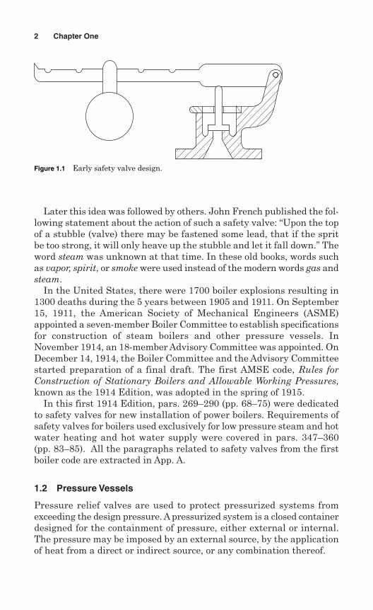
Papin kept the safety valve closed by means of a lever and a movableweight. Sliding the weight along the lever kept the valve in place andregulated the steam pressure (Fig. 1.1). It is supposed that Papin wasthe inventor of the improvements to safety valves that were used byGlauber, a German.
Glauber contributed many scientific ideas to mechanical engineering.In his treatise on furnaces, translated into English in 1651, he describedthe modes by which he prevented retorts and stills from bursting fromexcessive pressure. He fitted a conical valve which was air-tight to its seatand loaded with a “cap of lead.” When the vapor pressure increased, itslightly raised the valve and a portion of vapor escaped. Then the valveclosed itself, “being pressed down by the loaded cap,” which kept it closed.
1
Copyright © 2006 by The McGraw-Hill Companies, Inc. Click here for terms of use.
Later this idea was followed by others. John French published the fol-lowing statement about the action of such a safety valve: “Upon the topof a stubble (valve) there may be fastened some lead, that if the spritbe too strong, it will only heave up the stubble and let it fall down.” Theword steam was unknown at that time. In these old books, words suchas vapor, spirit, or smoke were used instead of the modern words gas andsteam.
In the United States, there were 1700 boiler explosions resulting in1300 deaths during the 5 years between 1905 and 1911. On September15, 1911, the American Society of Mechanical Engineers (ASME)appointed a seven-member Boiler Committee to establish specificationsfor construction of steam boilers and other pressure vessels. InNovember 1914, an 18-member Advisory Committee was appointed. OnDecember 14, 1914, the Boiler Committee and the Advisory Committeestarted preparation of a final draft. The first AMSE code, Rules forConstruction of Stationary Boilers and Allowable Working Pressures,known as the 1914 Edition, was adopted in the spring of 1915.
In this first 1914 Edition, pars. 269–290 (pp. 68–75) were dedicatedto safety valves for new installation of power boilers. Requirements ofsafety valves for boilers used exclusively for low pressure steam and hotwater heating and hot water supply were covered in pars. 347–360(pp. 83–85). All the paragraphs related to safety valves from the firstboiler code are extracted in App. A.
1.2 Pressure Vessels
Pressure relief valves are used to protect pressurized systems fromexceeding the design pressure. A pressurized system is a closed containerdesigned for the containment of pressure, either external or internal.The pressure may be imposed by an external source, by the applicationof heat from a direct or indirect source, or any combination thereof.
2 Chapter One
Figure 1.1 Early safety valve design.
There are many types of pressure vessels, but they are generally clas-sified into two basic categories:
1. Fired pressure vessels: In this category, fuels are burned to produceheat, which in turn boils water to generate steam. Examples of firedpressure vessels include steam boilers, hot water boilers, hot waterheaters, etc.
2. Unfired pressure vessels: Vessels in this category are used for storageof liquid, gas, or vapor at pressures of more than 15 psig (103 kPa).Examples of unfired pressure vessels include air tanks, heat exchang-ers, expansion tanks, feedwater heaters, columns, towers, drums,reactors, condensers, air coolers, oil coolers, accumulators, digesters,gas cylinders, and various pressurized systems used in industry. Theword “pressure vessel” is a general term which includes all types ofunfired pressure vessel.
When a substance is stored under pressure, the potential for rup-ture and leakage exists. Improper vessel design, operation, or main-tenance increase the risk of pressure vessel failure, posing a serioussafety hazard. The risk increases when vessels contain toxic or gaseoussubstances.
Every year, accidents occur to many pressure vessels that are in usein industry. Pressure vessels accidents can be very serious. A seriousaccident may not only take human lives but can damage valuable prop-erty, and can increase costs because of production downtime. Properlydesigned pressure relief valves with proper operation and maintenancecan prevent serious accidents to pressure vessels.
1.2.1 Boiler accidents
Many boiler accidents occur throughout the world each year. There arevarious causes of boiler accidents, but the most common cause is the fail-ure of a pressure relief valve. Here is an example of a catastrophic acci-dent involving a water heater that resulted from failure of a temperatureand pressure (T&P) relief valve.
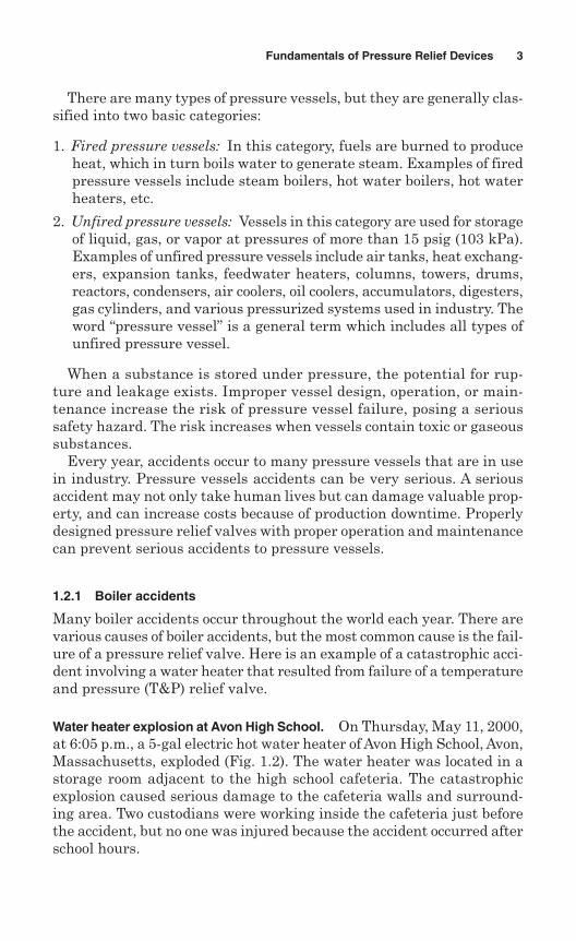
Water heater explosion at Avon High School. On Thursday, May 11, 2000,at 6:05 p.m., a 5-gal electric hot water heater of Avon High School, Avon,Massachusetts, exploded (Fig. 1.2). The water heater was located in astorage room adjacent to the high school cafeteria. The catastrophicexplosion caused serious damage to the cafeteria walls and surround-ing area. Two custodians were working inside the cafeteria just beforethe accident, but no one was injured because the accident occurred afterschool hours.
Fundamentals of Pressure Relief Devices 3
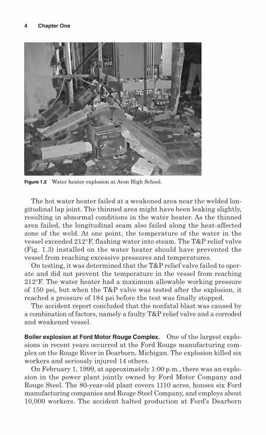
The hot water heater failed at a weakened area near the welded lon-gitudinal lap joint. The thinned area might have been leaking slightly,resulting in abnormal conditions in the water heater. As the thinnedarea failed, the longitudinal seam also failed along the heat-affectedzone of the weld. At one point, the temperature of the water in thevessel exceeded 212°F, flashing water into steam. The T&P relief valve(Fig. 1.3) installed on the water heater should have prevented thevessel from reaching excessive pressures and temperatures.
On testing, it was determined that the T&P relief valve failed to oper-ate and did not prevent the temperature in the vessel from reaching212°F. The water heater had a maximum allowable working pressureof 150 psi, but when the T&P valve was tested after the explosion, itreached a pressure of 184 psi before the test was finally stopped.
The accident report concluded that the nonfatal blast was caused bya combination of factors, namely a faulty T&P relief valve and a corrodedand weakened vessel.
Boiler explosion at Ford Motor Rouge Complex. One of the largest explo-sions in recent years occurred at the Ford Rouge manufacturing com-plex on the Rouge River in Dearborn, Michigan. The explosion killed sixworkers and seriously injured 14 others.
On February 1, 1999, at approximately 1:00 p.m., there was an explo-sion in the power plant jointly owned by Ford Motor Company andRouge Steel. The 80-year-old plant covers 1110 acres, houses six Fordmanufacturing companies and Rouge Steel Company, and employs about10,000 workers. The accident halted production at Ford’s Dearborn
4 Chapter One
Figure 1.2 Water heater explosion at Avon High School.
assembly plants, which makes Mustangs, at the five other Ford plantswhich supply a variety of automotive parts to most of Ford’s assemblyplants in North America, and at Rouge Steel Company, which producessteel for the automotive industry.
About 140 workers were employed at the power plant, which wasscheduled to be replaced with a new facility in 2000. The Rouge powerplant produced steam by burning a mixture of natural gas, pulverizedcoal, and blast furnace gas.
The investigation report concluded that the explosion was caused bya natural gas buildup in Boiler No. 6. The buildup was a result of inad-equate controls for safety shutdown.
The Michigan Department of Consumer & Industry Services (CIS)concluded its 7-month investigation of this fatal explosion with anunprecedented and historic $7 million settlement agreement with FordMotor Company and the United Auto Workers Union (UAW). This agree-ment did not include the private settlement offers Ford Motor Companymade to the victims and their families.
1.2.2 Pressure vessel accidents
Any pressure vessel accident, like any boiler accident, is dangerous.Most of the time a pressure vessel contains gas and liquid, which areharmful when explosion occurs.
Federal Occupational Safety and Health Administration (OSHA) sta-tistics show that 13 people were injured in 1999, one person was killed
Fundamentals of Pressure Relief Devices 5
Figure 1.3 T&P pressure relief valve after explosion.
in 1998, three people were injured in 1997, and nine people were killedin 1996 as a result of pressure vessel accidents. An industrial surveyshows that there were 1550 accidents to unfired pressure vessels in2003, resulting in five fatalities and 22 injuries. Here is an example ofa catastrophic pressure vessel accident in recent years:
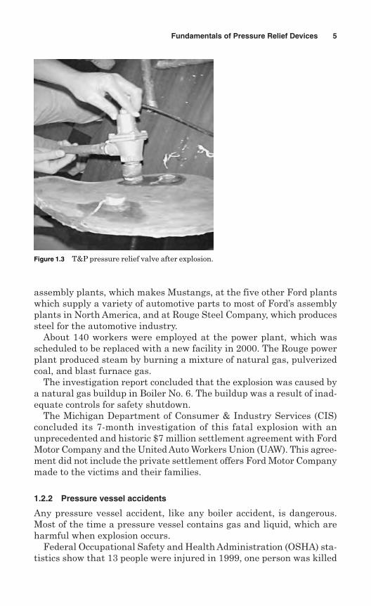
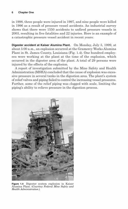
Digester accident at Kaiser Alumina Plant. On Monday, July 5, 1999, atabout 5:00 a.m., an explosion occurred at the Gramercy Works AluminaPlant in St. James County, Louisiana (Fig. 1.4). One hundred employ-ees were working at the plant at the time of the explosion, whichoccurred in the digester area of the plant. A total of 29 persons wereinjured by the effects of the explosion.
A report of investigation submitted by the Mine Safety and HealthAdministration (MSHA) concluded that the cause of explosion was exces-sive pressure in several tanks in the digestion area. The plant’s systemof relief valves and piping failed to control the increasing vessel pressures.Further, some of the relief piping was clogged with scale, limiting thepiping’s ability to relieve pressure in the digestion process.
6 Chapter One
Figure 1.4 Digester system explosion in KaiserAlumina Plant. (Courtesy Federal Mine Safety andHealth Administration.)
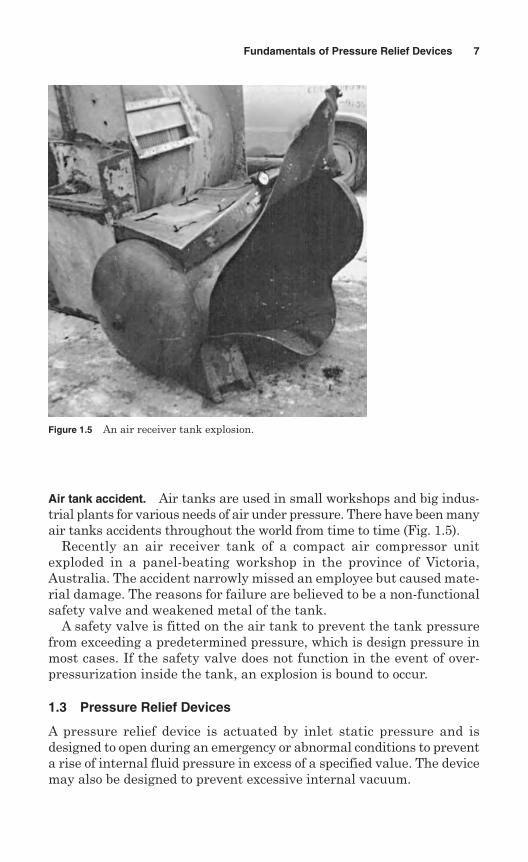
Air tank accident. Air tanks are used in small workshops and big indus-trial plants for various needs of air under pressure. There have been manyair tanks accidents throughout the world from time to time (Fig. 1.5).
Recently an air receiver tank of a compact air compressor unitexploded in a panel-beating workshop in the province of Victoria,Australia. The accident narrowly missed an employee but caused mate-rial damage. The reasons for failure are believed to be a non-functionalsafety valve and weakened metal of the tank.
A safety valve is fitted on the air tank to prevent the tank pressurefrom exceeding a predetermined pressure, which is design pressure inmost cases. If the safety valve does not function in the event of over-pressurization inside the tank, an explosion is bound to occur.
1.3 Pressure Relief Devices
A pressure relief device is actuated by inlet static pressure and isdesigned to open during an emergency or abnormal conditions to preventa rise of internal fluid pressure in excess of a specified value. The devicemay also be designed to prevent excessive internal vacuum.
Fundamentals of Pressure Relief Devices 7
Figure 1.5 An air receiver tank explosion.
Pressure relief devices protect a vessel against overpressure only.These devices do not protect against structural failure when the vesselis exposed to abnormal conditions such as high temperature due to fire.
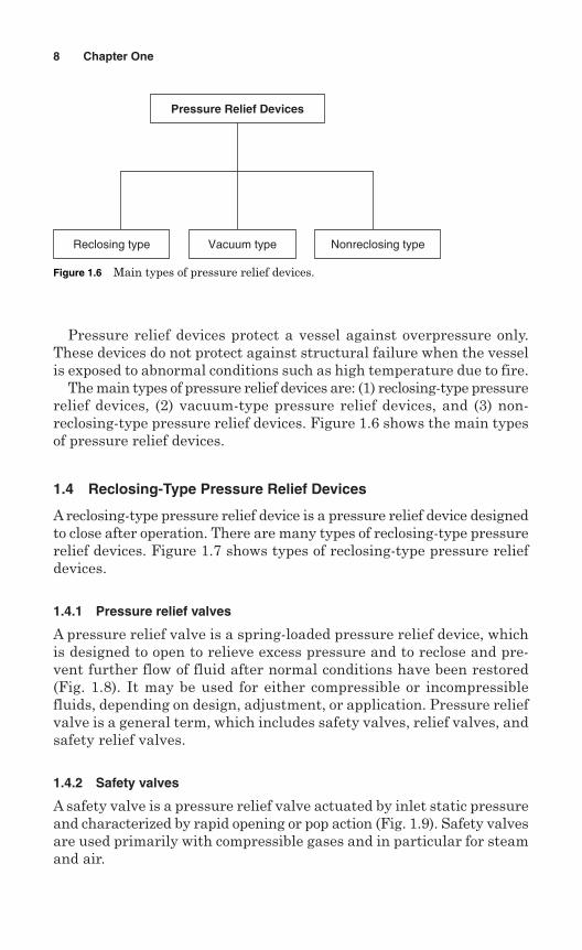
The main types of pressure relief devices are: (1) reclosing-type pressurerelief devices, (2) vacuum-type pressure relief devices, and (3) non-reclosing-type pressure relief devices. Figure 1.6 shows the main typesof pressure relief devices.
1.4 Reclosing-Type Pressure Relief Devices
A reclosing-type pressure relief device is a pressure relief device designedto close after operation. There are many types of reclosing-type pressurerelief devices. Figure 1.7 shows types of reclosing-type pressure reliefdevices.
1.4.1 Pressure relief valves
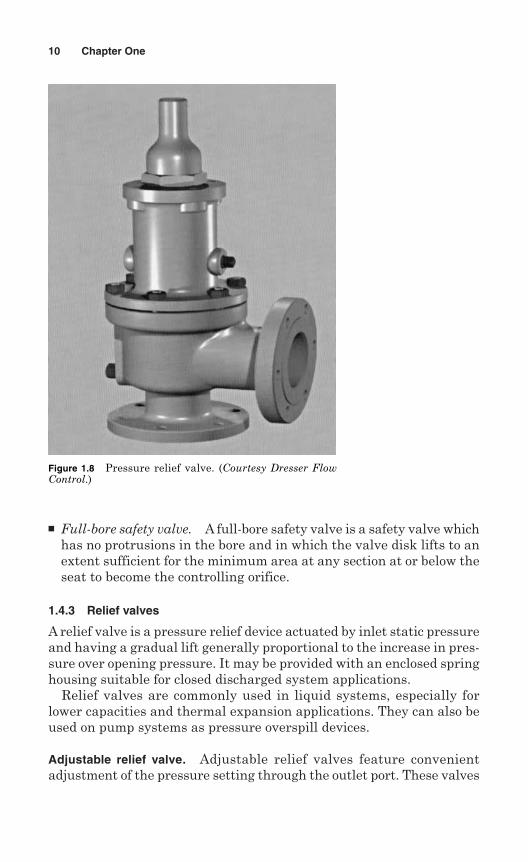
A pressure relief valve is a spring-loaded pressure relief device, whichis designed to open to relieve excess pressure and to reclose and pre-vent further flow of fluid after normal conditions have been restored(Fig. 1.8). It may be used for either compressible or incompressiblefluids, depending on design, adjustment, or application. Pressure reliefvalve is a general term, which includes safety valves, relief valves, andsafety relief valves.
1.4.2 Safety valves
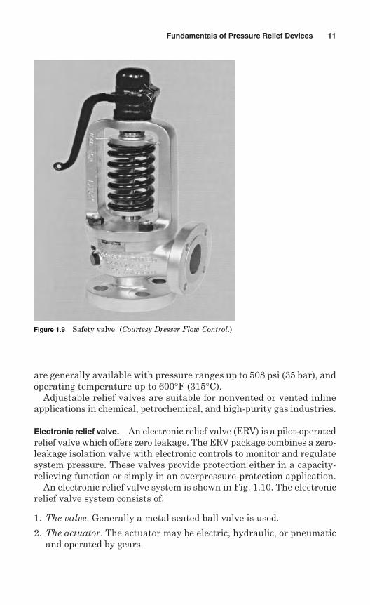
A safety valve is a pressure relief valve actuated by inlet static pressureand characterized by rapid opening or pop action (Fig. 1.9). Safety valvesare used primarily with compressible gases and in particular for steamand air.
8 Chapter One
Pressure Relief Devices
Reclosing type Nonreclosing typeVacuum type
Figure 1.6 Main types of pressure relief devices.
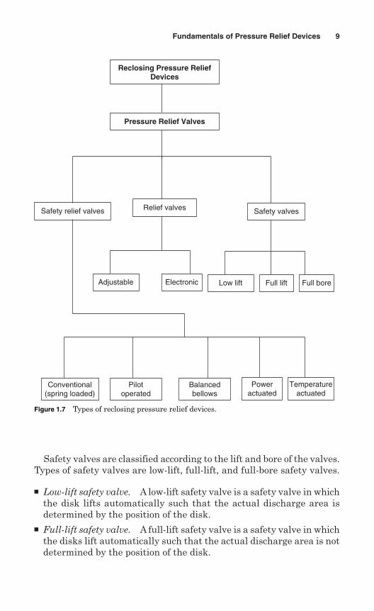
Safety valves are classified according to the lift and bore of the valves.Types of safety valves are low-lift, full-lift, and full-bore safety valves.
Low-lift safety valve. A low-lift safety valve is a safety valve in whichthe disk lifts automatically such that the actual discharge area isdetermined by the position of the disk.
Full-lift safety valve. A full-lift safety valve is a safety valve in whichthe disks lift automatically such that the actual discharge area is notdetermined by the position of the disk.
Fundamentals of Pressure Relief Devices 9
Pressure Relief Valves
Safety relief valves Safety valves
Low lift Full lift Full bore
Conventional(spring loaded)
Pilotoperated
Balancedbellows
Relief valves
Adjustable Electronic
Poweractuated
Temperatureactuated
Reclosing Pressure ReliefDevices
Figure 1.7 Types of reclosing pressure relief devices.
Full-bore safety valve. A full-bore safety valve is a safety valve whichhas no protrusions in the bore and in which the valve disk lifts to anextent sufficient for the minimum area at any section at or below theseat to become the controlling orifice.
1.4.3 Relief valves
A relief valve is a pressure relief device actuated by inlet static pressureand having a gradual lift generally proportional to the increase in pres-sure over opening pressure. It may be provided with an enclosed springhousing suitable for closed discharged system applications.
Relief valves are commonly used in liquid systems, especially forlower capacities and thermal expansion applications. They can also beused on pump systems as pressure overspill devices.
Adjustable relief valve. Adjustable relief valves feature convenientadjustment of the pressure setting through the outlet port. These valves
10 Chapter One
Figure 1.8 Pressure relief valve. (Courtesy Dresser FlowControl.)
are generally available with pressure ranges up to 508 psi (35 bar), andoperating temperature up to 600°F (315°C).
Adjustable relief valves are suitable for nonvented or vented inlineapplications in chemical, petrochemical, and high-purity gas industries.
Electronic relief valve. An electronic relief valve (ERV) is a pilot-operatedrelief valve which offers zero leakage. The ERV package combines a zero-leakage isolation valve with electronic controls to monitor and regulatesystem pressure. These valves provide protection either in a capacity-relieving function or simply in an overpressure-protection application.
An electronic relief valve system is shown in Fig. 1.10. The electronicrelief valve system consists of:
1. The valve. Generally a metal seated ball valve is used.
2. The actuator. The actuator may be electric, hydraulic, or pneumaticand operated by gears.
Fundamentals of Pressure Relief Devices 11
Figure 1.9 Safety valve. (Courtesy Dresser Flow Control.)
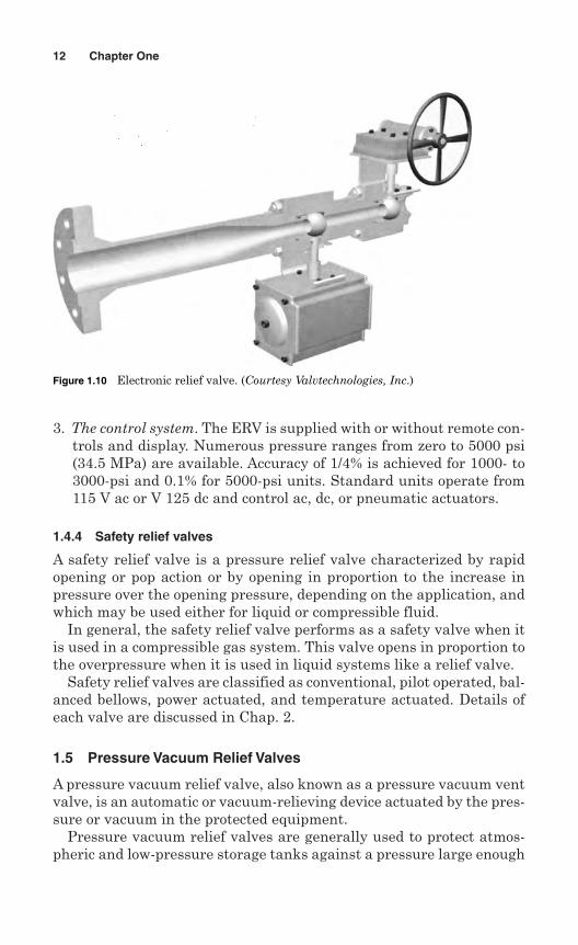
3. The control system. The ERV is supplied with or without remote con-trols and display. Numerous pressure ranges from zero to 5000 psi(34.5 MPa) are available. Accuracy of 1/4% is achieved for 1000- to3000-psi and 0.1% for 5000-psi units. Standard units operate from115 V ac or V 125 dc and control ac, dc, or pneumatic actuators.
1.4.4 Safety relief valves
A safety relief valve is a pressure relief valve characterized by rapidopening or pop action or by opening in proportion to the increase inpressure over the opening pressure, depending on the application, andwhich may be used either for liquid or compressible fluid.
In general, the safety relief valve performs as a safety valve when itis used in a compressible gas system. This valve opens in proportion tothe overpressure when it is used in liquid systems like a relief valve.
Safety relief valves are classified as conventional, pilot operated, bal-anced bellows, power actuated, and temperature actuated. Details ofeach valve are discussed in Chap. 2.
1.5 Pressure Vacuum Relief Valves
A pressure vacuum relief valve, also known as a pressure vacuum ventvalve, is an automatic or vacuum-relieving device actuated by the pres-sure or vacuum in the protected equipment.
Pressure vacuum relief valves are generally used to protect atmos-pheric and low-pressure storage tanks against a pressure large enough
12 Chapter One
Figure 1.10 Electronic relief valve. (Courtesy Valvtechnologies, Inc.)
to damage the tank. Pressure vacuum relief valves are not used forapplications requiring a set pressure of more than 15 lbf/in.2 (103 kPa).
Pressure vacuum relief valves are classified into three categories(Fig. 1.11): (1) pressure vacuum vent valves, (2) pressure relief valves,and (3) vacuum relief valves.
1.5.1 Pressure vacuum vent valves
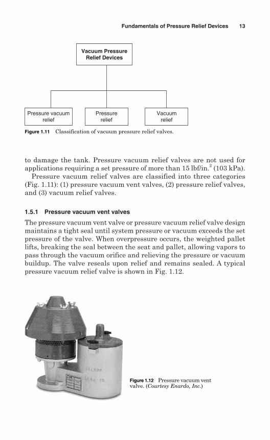
The pressure vacuum vent valve or pressure vacuum relief valve designmaintains a tight seal until system pressure or vacuum exceeds the setpressure of the valve. When overpressure occurs, the weighted palletlifts, breaking the seal between the seat and pallet, allowing vapors topass through the vacuum orifice and relieving the pressure or vacuumbuildup. The valve reseals upon relief and remains sealed. A typicalpressure vacuum relief valve is shown in Fig. 1.12.
Fundamentals of Pressure Relief Devices 13
Vacuum Pressure Relief Devices
Pressure vacuum relief
Pressurerelief
Vacuumrelief
Figure 1.11 Classification of vacuum pressure relief valves.
Figure 1.12 Pressure vacuum ventvalve. (Courtesy Enardo, Inc.)
1.5.2 Pressure relief valves
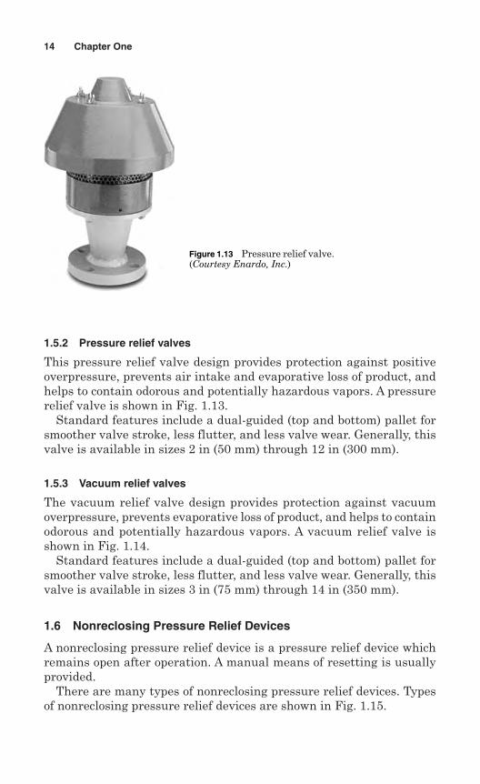
This pressure relief valve design provides protection against positiveoverpressure, prevents air intake and evaporative loss of product, andhelps to contain odorous and potentially hazardous vapors. A pressurerelief valve is shown in Fig. 1.13.
Standard features include a dual-guided (top and bottom) pallet forsmoother valve stroke, less flutter, and less valve wear. Generally, thisvalve is available in sizes 2 in (50 mm) through 12 in (300 mm).
1.5.3 Vacuum relief valves
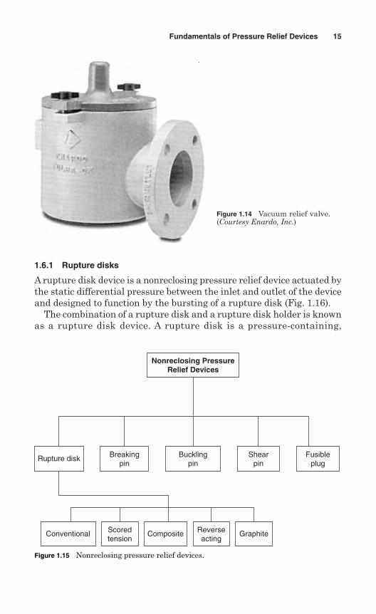
The vacuum relief valve design provides protection against vacuumoverpressure, prevents evaporative loss of product, and helps to containodorous and potentially hazardous vapors. A vacuum relief valve isshown in Fig. 1.14.
Standard features include a dual-guided (top and bottom) pallet forsmoother valve stroke, less flutter, and less valve wear. Generally, thisvalve is available in sizes 3 in (75 mm) through 14 in (350 mm).
1.6 Nonreclosing Pressure Relief Devices
A nonreclosing pressure relief device is a pressure relief device whichremains open after operation. A manual means of resetting is usuallyprovided.
There are many types of nonreclosing pressure relief devices. Typesof nonreclosing pressure relief devices are shown in Fig. 1.15.
14 Chapter One
Figure 1.13 Pressure relief valve.(Courtesy Enardo, Inc.)
1.6.1 Rupture disks
A rupture disk device is a nonreclosing pressure relief device actuated bythe static differential pressure between the inlet and outlet of the deviceand designed to function by the bursting of a rupture disk (Fig. 1.16).
The combination of a rupture disk and a rupture disk holder is knownas a rupture disk device. A rupture disk is a pressure-containing,
Fundamentals of Pressure Relief Devices 15
Figure 1.14 Vacuum relief valve.(Courtesy Enardo, Inc.)
Rupture disk Bucklingpin
Fusibleplug
Conventional Scoredtension
Composite Reverseacting
Graphite
Nonreclosing Pressure Relief Devices
Shearpin
Breakingpin
Figure 1.15 Nonreclosing pressure relief devices.
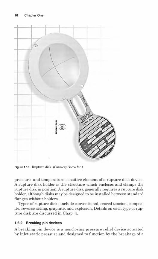
pressure- and temperature-sensitive element of a rupture disk device.A rupture disk holder is the structure which encloses and clamps therupture disk in position. A rupture disk generally requires a rupture diskholder, although disks may be designed to be installed between standardflanges without holders.
Types of rupture disks include conventional, scored tension, compos-ite, reverse acting, graphite, and explosion. Details on each type of rup-ture disk are discussed in Chap. 4.
1.6.2 Breaking pin devices
A breaking pin device is a nonclosing pressure relief device actuatedby inlet static pressure and designed to function by the breakage of a
16 Chapter One
Figure 1.16 Rupture disk. (Courtesy Oseco Inc.)
load-carrying section of a pin which supports a pressure-containingmember.
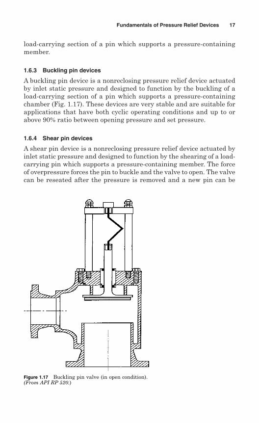
1.6.3 Buckling pin devices
A buckling pin device is a nonreclosing pressure relief device actuatedby inlet static pressure and designed to function by the buckling of aload-carrying section of a pin which supports a pressure-containingchamber (Fig. 1.17). These devices are very stable and are suitable forapplications that have both cyclic operating conditions and up to orabove 90% ratio between opening pressure and set pressure.
1.6.4 Shear pin devices
A shear pin device is a nonreclosing pressure relief device actuated byinlet static pressure and designed to function by the shearing of a load-carrying pin which supports a pressure-containing member. The forceof overpressure forces the pin to buckle and the valve to open. The valvecan be reseated after the pressure is removed and a new pin can be
Fundamentals of Pressure Relief Devices 17
Figure 1.17 Buckling pin valve (in open condition).(From API RP 520.)
installed. These devices are usually installed on low-pressure applica-tions and large gas distribution systems. They have limited processapplications.
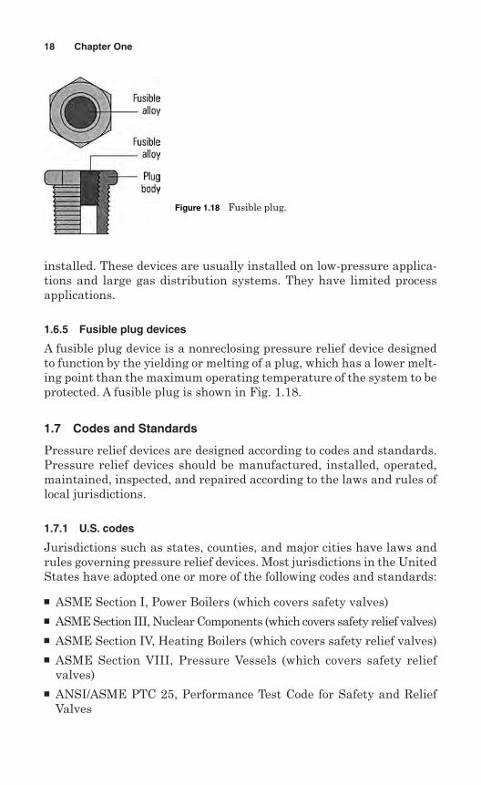
1.6.5 Fusible plug devices
A fusible plug device is a nonreclosing pressure relief device designedto function by the yielding or melting of a plug, which has a lower melt-ing point than the maximum operating temperature of the system to beprotected. A fusible plug is shown in Fig. 1.18.
1.7 Codes and Standards
Pressure relief devices are designed according to codes and standards.Pressure relief devices should be manufactured, installed, operated,maintained, inspected, and repaired according to the laws and rules oflocal jurisdictions.
1.7.1 U.S. codes
Jurisdictions such as states, counties, and major cities have laws andrules governing pressure relief devices. Most jurisdictions in the UnitedStates have adopted one or more of the following codes and standards:
ASME Section I, Power Boilers (which covers safety valves) ASME Section III, Nuclear Components (which covers safety relief valves) ASME Section IV, Heating Boilers (which covers safety relief valves) ASME Section VIII, Pressure Vessels (which covers safety relief
valves) ANSI/ASME PTC 25, Performance Test Code for Safety and Relief
Valves
18 Chapter One
Figure 1.18 Fusible plug.
API RP520 Part I, Sizing and Selection of Pressure Relieving Devicesin Refineries
API RP520 Part II, Installation of Pressure Relieving Devices inRefineries
API RP521, Guide for Pressure Relief and De-pressurizing Systems API RP526, Flanged Steel Safety/Relief Valves for use in the Petroleum
Industry API RP527, Commercial Seat Tightness of Safety/Relief Valves with
Metal to Metal and Soft Seals
1.7.2 International codes
There are international codes available on pressure relief devices. Mostof the developed countries have their own codes and standards fordesign, construction, operation, and inspection of pressure relief devices.
Codes and standards of some countries are given below.
CanadaCSA B51, Boiler, Pressure Vessel, and Pressure Piping CodeCSA Z299.2.85, Quality Assurance Program Category 1CSA Z299.3.85, Quality Assurance Program Category 2CSA Z299.4.85, Quality Assurance Program Category 3
United KingdomBS 6759 Part 1, Specification for Safety Valves for Steam and HotWaterBS 6759 Part 2, Specification for Safety Valves for Compressed Air Andinert gasBS 6759 Part 3, Specification for Safety Valves for Process Fluids
GermanyMerkblatt 22, Pressure Vessel Equipment Safety Devices againstEXCESS pressure—Safety ValvesTRD 421, Technical Equipment for Steam Boilers Safeguards againstExcessive Pressure—Safety Valves for Boilers of Groups I, III, and IVTRD 721, Technical Equipment for Steam Boilers Safeguards againstExcessive Pressures—Safety Valves for Steam Boilers Group
FranceAFNOR NFE-E-29-411 to 416, Safety and Relief ValvesAFNOR NFE-E-29-421, Safety and Relief Valves
EuropeEN ISO 4126, Safety Devices for Protection against Excessive PressurePrEN ISO 4126-1, Safety Devices for Protection against ExcessivePressure—Part 1: Safety Valves
Fundamentals of Pressure Relief Devices 19
PrEN ISO 4126-2, Safety Devices for Protection against ExcessivePressure—Part 2: Bursting Disk Safety DevicesPrEN ISO 4126-3, Safety Devices for Protection against ExcessivePressure—Part 3: Safety Valves and Bursting Disk Safety Devices inCombinationPrEN ISO 4126-4, Safety Devices for Protection against ExcessivePressure—Part 4: Pilot-Operated Safety ValvesPrEN ISO 4126-5, Safety Devices for Protection against ExcessivePressure—Part 5: Controlled Safety Pressure Relief Systems (CSPRS)PrEN ISO 4126-6, Safety Devices for Protection against ExcessivePressure—Part 6: Application, Selection, and Installation of BurstingDisk Safety DevicesPrEN ISO 4126-7, Safety Devices for Protection against ExcessivePressure—Part 7: Common Data
RomaniaRomanian Pressure Vessel Standard
RussiaGOST R, Certification System
SwitzerlandSpecifications 62, Safety Valves for Boilers and Pressure Vessels
HollandA1301, Stoomwezen Specification
NorwayTBK, General Rules for Pressure Vessels
KoreaKS B 6216, Spring-Loaded Safety Valves for Steam Boilers andPressure Vessels
JapanJIS B 8210, Steam Boilers and Pressure Vessels—Spring-LoadedSafety Valves
AustraliaAS1271, Safety Valves, Other Valves, Liquid Level Gauges and OtherFittings for Boilers and Unfired Pressure VesselsAS121, Unfired Pressure VesselsAS1200, Pressure Equipment
1.8 Jurisdictional Authority
A jurisdiction is a government authority such as a municipality, county,state, province, or country. The codes and standards for pressure reliefdevices become mandatory only when adopted by the jurisdictions
20 Chapter One
having authority over locations where pressure relief devices areinstalled.
Adoption of the codes and standards is accomplished through leg-islative action requiring that pressure relief devices fitted on pressurevessels for use within the jurisdiction must comply with the ASME,API, or other codes. Designated officials such as chief boiler and pres-sure vessel inspector and his or her staff enforce the legal requirementsof the jurisdictions. Legal requirements for pressure relief valves varyfrom jurisdiction to jurisdiction.
In some jurisdictions there are no requirements for pressure reliefdevices. In such cases, the owner must use good engineering practicesfor design, selection, installation, operation, and maintenance to avoiddangers of pressure vessel and piping explosion.
Fundamentals of Pressure Relief Devices 21

This page intentionally left blank
Chapter
2Pressure Relief Valves
A pressure relief device is a safety device used on pressurized equipmentto protect life and property when all other safety measures fail. TheASME and API codes require that all pressure vessels subject to over-pressure must be protected by a pressure-relieving device. The codes fur-ther state that:
Liquid-filled vessels or piping subject to thermal expansion should beprotected by a thermal relief device.
Multiple vessels should be protected by a single relief device, pro-vided there is a clear, unobstructed path to the device.
At least one pressure relief device should be set at or below the max-imum allowable working pressure (MAWP).
Relieving pressure should not exceed MAWP (accumulation) by morethan:- 3% for fired and unfired steam boilers- 10% for vessels equipped with a single pressure relief device- 16% for vessels equipped with multiple pressure relief devices- 21% for fire contingency
A pressure relief valve is a pressure relief device. Its primary purposeis to prevent pressure in the system from increasing beyond safe designlimits. The secondary purpose of a pressure relief valve is to minimizedamage to other system components as a result of operation of the pres-sure relief valve itself.
The following are advantages of pressure relief valves:
Most reliable if properly sized and operated Versatile—can be used for many services
23
Copyright © 2006 by The McGraw-Hill Companies, Inc. Click here for terms of use.
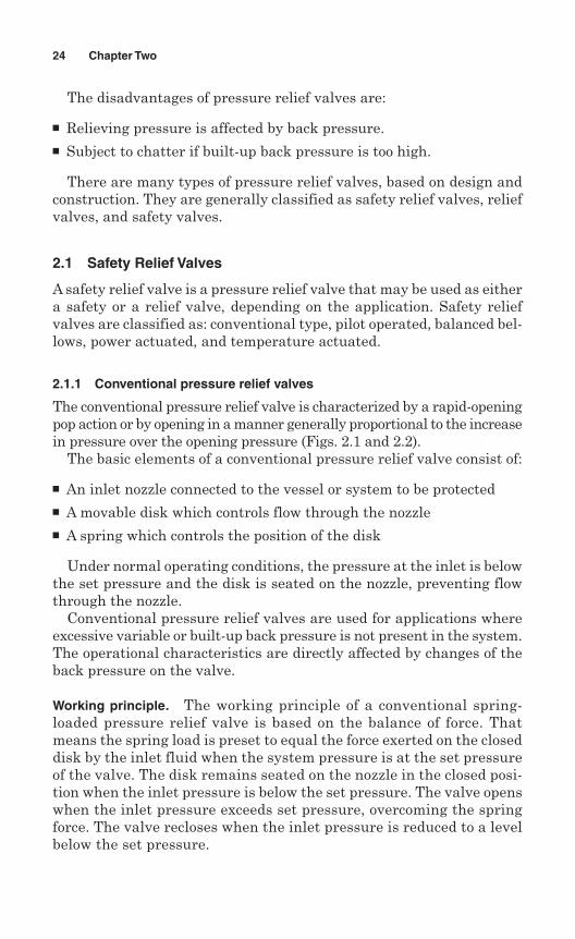
The disadvantages of pressure relief valves are:
Relieving pressure is affected by back pressure. Subject to chatter if built-up back pressure is too high.
There are many types of pressure relief valves, based on design andconstruction. They are generally classified as safety relief valves, reliefvalves, and safety valves.
2.1 Safety Relief Valves
A safety relief valve is a pressure relief valve that may be used as eithera safety or a relief valve, depending on the application. Safety reliefvalves are classified as: conventional type, pilot operated, balanced bel-lows, power actuated, and temperature actuated.
2.1.1 Conventional pressure relief valves
The conventional pressure relief valve is characterized by a rapid-openingpop action or by opening in a manner generally proportional to the increasein pressure over the opening pressure (Figs. 2.1 and 2.2).
The basic elements of a conventional pressure relief valve consist of:
An inlet nozzle connected to the vessel or system to be protected A movable disk which controls flow through the nozzle A spring which controls the position of the disk
Under normal operating conditions, the pressure at the inlet is belowthe set pressure and the disk is seated on the nozzle, preventing flowthrough the nozzle.
Conventional pressure relief valves are used for applications whereexcessive variable or built-up back pressure is not present in the system.The operational characteristics are directly affected by changes of theback pressure on the valve.
Working principle. The working principle of a conventional spring-loaded pressure relief valve is based on the balance of force. Thatmeans the spring load is preset to equal the force exerted on the closeddisk by the inlet fluid when the system pressure is at the set pressureof the valve. The disk remains seated on the nozzle in the closed posi-tion when the inlet pressure is below the set pressure. The valve openswhen the inlet pressure exceeds set pressure, overcoming the springforce. The valve recloses when the inlet pressure is reduced to a levelbelow the set pressure.
24 Chapter Two
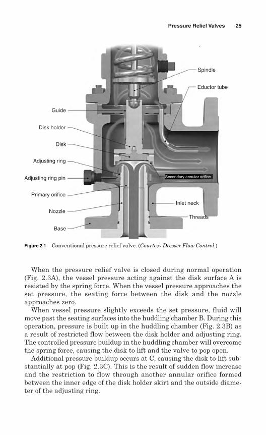
When the pressure relief valve is closed during normal operation(Fig. 2.3A), the vessel pressure acting against the disk surface A isresisted by the spring force. When the vessel pressure approaches theset pressure, the seating force between the disk and the nozzleapproaches zero.
When vessel pressure slightly exceeds the set pressure, fluid willmove past the seating surfaces into the huddling chamber B. During thisoperation, pressure is built up in the huddling chamber (Fig. 2.3B) asa result of restricted flow between the disk holder and adjusting ring.The controlled pressure buildup in the huddling chamber will overcomethe spring force, causing the disk to lift and the valve to pop open.
Additional pressure buildup occurs at C, causing the disk to lift sub-stantially at pop (Fig. 2.3C). This is the result of sudden flow increaseand the restriction to flow through another annular orifice formedbetween the inner edge of the disk holder skirt and the outside diame-ter of the adjusting ring.
Pressure Relief Valves 25
Guide
Disk holder
Disk
Adjusting ring
Adjusting ring pin
Primary orifice
Nozzle
Base
Threads
Inlet neck
Secondary annular orifice
Spindle
Eductor tube
Figure 2.1 Conventional pressure relief valve. (Courtesy Dresser Flow Control.)
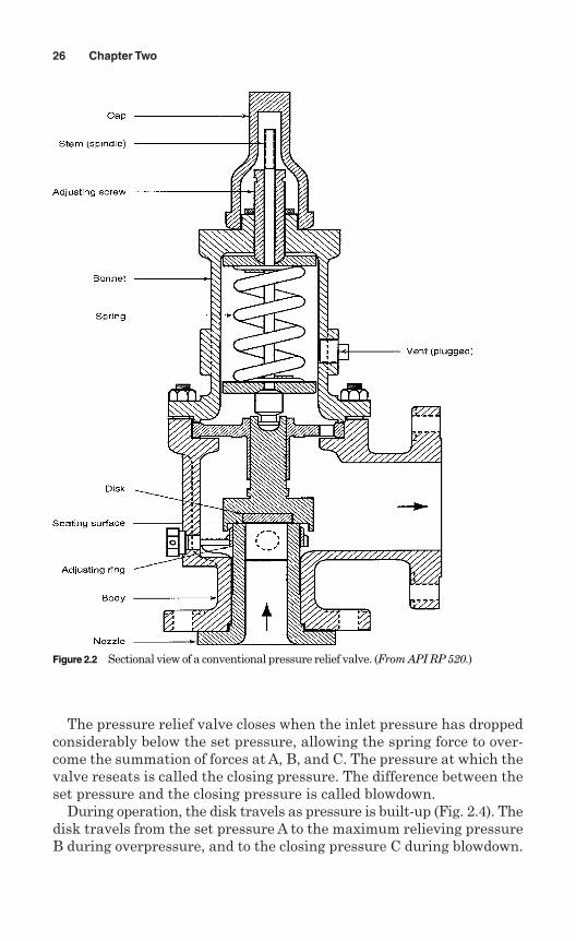
The pressure relief valve closes when the inlet pressure has droppedconsiderably below the set pressure, allowing the spring force to over-come the summation of forces at A, B, and C. The pressure at which thevalve reseats is called the closing pressure. The difference between theset pressure and the closing pressure is called blowdown.
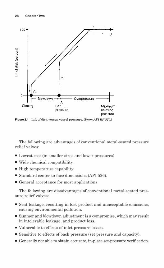
During operation, the disk travels as pressure is built-up (Fig. 2.4). Thedisk travels from the set pressure A to the maximum relieving pressureB during overpressure, and to the closing pressure C during blowdown.
26 Chapter Two
Figure 2.2 Sectional view of a conventional pressure relief valve. (From API RP 520.)
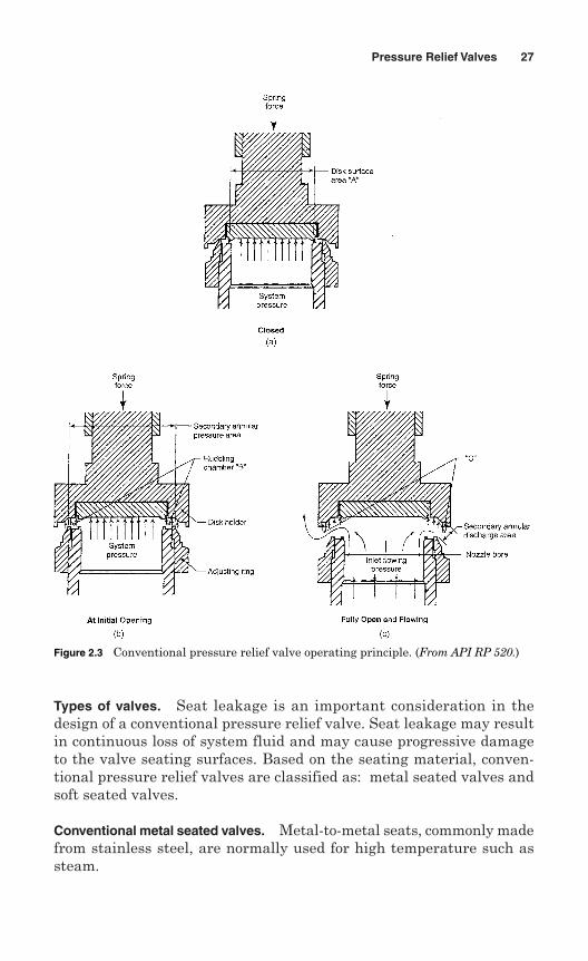
Types of valves. Seat leakage is an important consideration in thedesign of a conventional pressure relief valve. Seat leakage may resultin continuous loss of system fluid and may cause progressive damageto the valve seating surfaces. Based on the seating material, conven-tional pressure relief valves are classified as: metal seated valves andsoft seated valves.
Conventional metal seated valves. Metal-to-metal seats, commonly madefrom stainless steel, are normally used for high temperature such assteam.
Pressure Relief Valves 27
Figure 2.3 Conventional pressure relief valve operating principle. (From API RP 520.)
The following are advantages of conventional metal-seated pressurerelief valves:
Lowest cost (in smaller sizes and lower pressures) Wide chemical compatibility High temperature capability Standard center-to-face dimensions (API 526). General acceptance for most applications
The following are disadvantages of conventional metal-seated pres-sure relief valves:
Seat leakage, resulting in lost product and unacceptable emissions,causing environmental pollution.
Simmer and blowdown adjustment is a compromise, which may resultin intolerable leakage, and product loss.
Vulnerable to effects of inlet pressure losses. Sensitive to effects of back pressure (set pressure and capacity). Generally not able to obtain accurate, in-place set-pressure verification.
28 Chapter Two
Figure 2.4 Lift of disk versus vessel pressure. (From API RP 520.)
Conventional soft seated valves. As alternative to metal, resilient diskscan be fixed to either or both the seating surfaces where tighter shut-offis required, specially for gas or liquid applications. These inserts may bemade from a number of different materials, but Viton, nitrile or EPDM arethe most common. Soft seal inserts are not recommended for steam use.
The conventional soft seated pressure relief valve has the followingadvantages:
Good seat tightness before relieving Good reseat tightness after relieving Good cycle life and maintained tightness Low maintenance costs
The conventional soft seated valve has the following disadvantages:
Temperature is limited to seat material used. Chemically limited according to soft goods used. Vulnerable to effects of inlet pressure losses.
2.1.2 Pilot-operated pressure relief valves
A pilot-operated pressure relief valve is a pressure relief valve in whichthe major relieving device is combined with and is controlled by a self-actuated auxiliary pressure relief valve (Fig. 2.5).
The primary difference between a pilot-operated pressure relief valveand a spring-loaded pressure relief valve is that the pilot-operated valveuses process pressure to keep the valve closed instead of a spring. A pilotis used to sense process pressure and to pressurize or vent the domepressure chamber which controls the valve opening or closing.
A pilot-operated pressure relief valve consists of the main valve, afloating unbalanced piston assembly, and an external pilot. The pilot con-trols the pressure on the top side of the main-valve unbalanced movingchamber. A resilient seat is normally attached to the lower end of thismember.
At pressures below set, the pressure on opposite sides of the movingmembers is equal.
When the set pressure is reached, the pilot opens, depressurizes thecavity on the top side and the unbalanced member moves upward,causing the main valve to relieve.
When the process pressure decreases to a predetermined pressure, thepilot closes, the cavity above the piston is depressurized, and the mainvalve closes.
Pressure Relief Valves 29
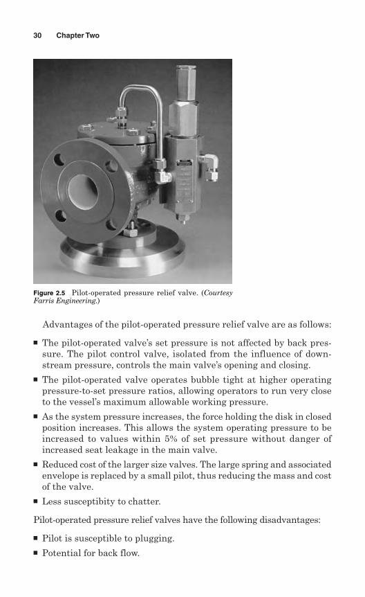
Advantages of the pilot-operated pressure relief valve are as follows:
The pilot-operated valve’s set pressure is not affected by back pres-sure. The pilot control valve, isolated from the influence of down-stream pressure, controls the main valve’s opening and closing.
The pilot-operated valve operates bubble tight at higher operatingpressure-to-set pressure ratios, allowing operators to run very closeto the vessel’s maximum allowable working pressure.
As the system pressure increases, the force holding the disk in closedposition increases. This allows the system operating pressure to beincreased to values within 5% of set pressure without danger ofincreased seat leakage in the main valve.
Reduced cost of the larger size valves. The large spring and associatedenvelope is replaced by a small pilot, thus reducing the mass and costof the valve.
Less susceptibity to chatter.
Pilot-operated pressure relief valves have the following disadvantages:
Pilot is susceptible to plugging. Potential for back flow.
30 Chapter Two
Figure 2.5 Pilot-operated pressure relief valve. (CourtesyFarris Engineering.)
Vapor condensation and liquid accumulation above the piston maycause problems.
Limited chemical and high-temperature use by “O-ring” seals.
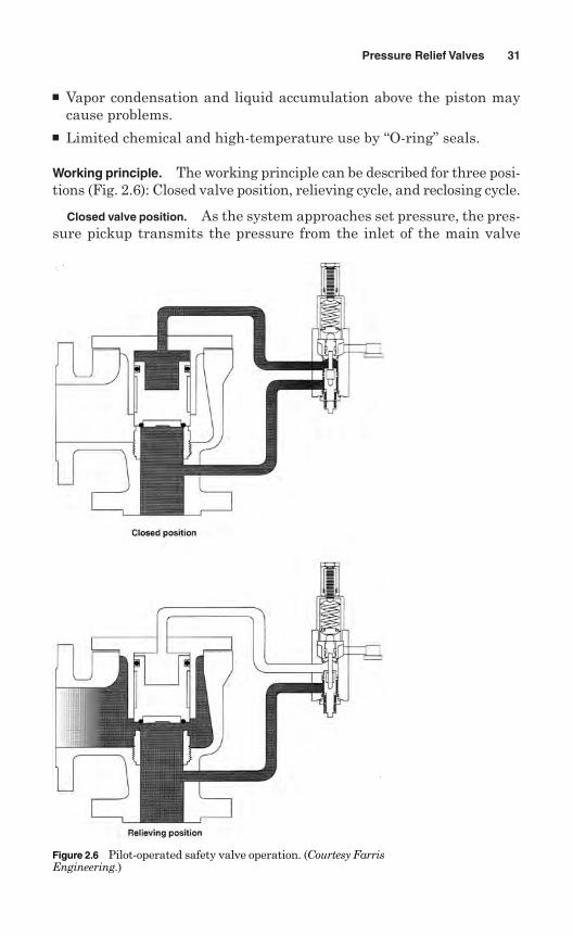
Working principle. The working principle can be described for three posi-tions (Fig. 2.6): Closed valve position, relieving cycle, and reclosing cycle.
Closed valve position. As the system approaches set pressure, the pres-sure pickup transmits the pressure from the inlet of the main valve
Pressure Relief Valves 31
Figure 2.6 Pilot-operated safety valve operation. (Courtesy FarrisEngineering.)
through the pilot control and into the dome of the main valve. Thispressure acts on the top of the piston in the dome, holding the pistonfirmly against the seat on the nozzle of the main valve.
Relieving cycle. When the inlet pressure overcomes the spring force inthe pilot valve, the pilot valve lifts. As the seat assembly in the pilotcontrol begins to lift, it seals off the flow of pressure to both the ventand the main valve dome. At that time, the pressure in the dome isreleased through the pilot vent. As the pressure in the dome has beenreleased, the system pressure acting on the bottom of the piston liftsthe piston and relieves system overpressure.
Reclosing cycle. When the system pressure blows down, the springforce in the pilot valve overcomes the force of the system acting on thepilot control seat assembly. The pilot control redirects system pressureback into the main valve dome, closing the main valve. Of course, blow-down can be adjusted by raising and lowering the blowdown adjusterposition in the pilot valve.
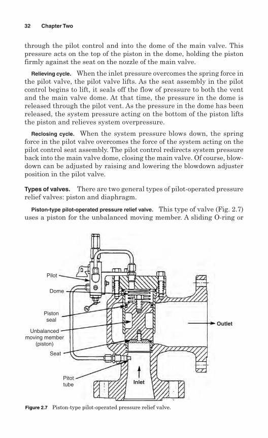
Types of valves. There are two general types of pilot-operated pressurerelief valves: piston and diaphragm.
Piston-type pilot-operated pressure relief valve. This type of valve (Fig. 2.7)uses a piston for the unbalanced moving member. A sliding O-ring or
32 Chapter Two
Pilot
Dome
Pistonseal
Unbalancedmoving member
(piston)
Seat
Pitottube Inlet
Outlet
Figure 2.7 Piston-type pilot-operated pressure relief valve.
spring-loaded plastic seal is used to obtain a pressure seal for the domeactivity. The piston-type valve is used for pressures from 5 to 10,000 psig,and occasionally for even higher pressures.
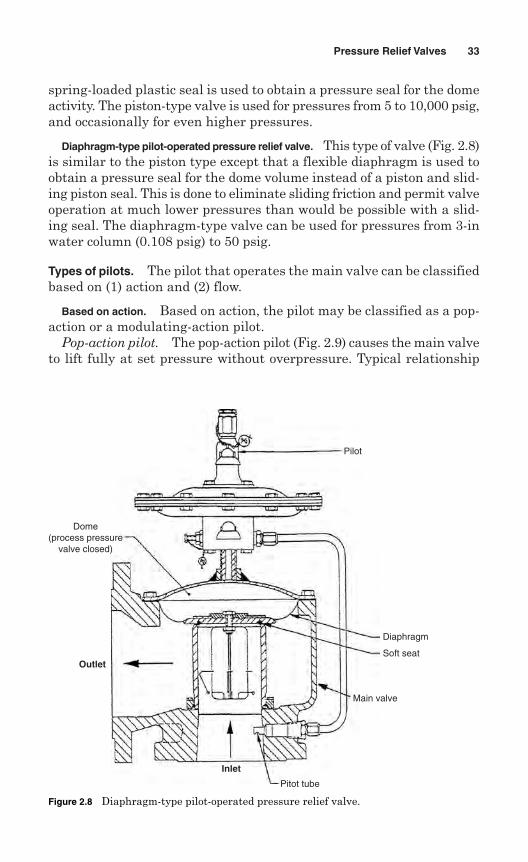
Diaphragm-type pilot-operated pressure relief valve. This type of valve (Fig. 2.8)is similar to the piston type except that a flexible diaphragm is used toobtain a pressure seal for the dome volume instead of a piston and slid-ing piston seal. This is done to eliminate sliding friction and permit valveoperation at much lower pressures than would be possible with a slid-ing seal. The diaphragm-type valve can be used for pressures from 3-inwater column (0.108 psig) to 50 psig.
Types of pilots. The pilot that operates the main valve can be classifiedbased on (1) action and (2) flow.
Based on action. Based on action, the pilot may be classified as a pop-action or a modulating-action pilot.
Pop-action pilot. The pop-action pilot (Fig. 2.9) causes the main valveto lift fully at set pressure without overpressure. Typical relationship
Pressure Relief Valves 33
Dome(process pressure
valve closed)
Outlet
Inlet
Pitot tube
Main valve
Soft seat
Diaphragm
Pilot
Figure 2.8 Diaphragm-type pilot-operated pressure relief valve.
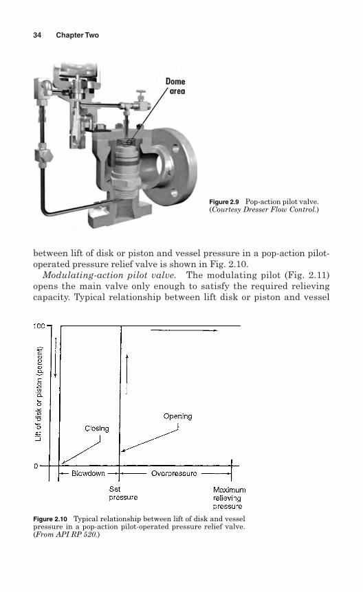
between lift of disk or piston and vessel pressure in a pop-action pilot-operated pressure relief valve is shown in Fig. 2.10.
Modulating-action pilot valve. The modulating pilot (Fig. 2.11)opens the main valve only enough to satisfy the required relievingcapacity. Typical relationship between lift disk or piston and vessel
34 Chapter Two
Figure 2.10 Typical relationship between lift of disk and vesselpressure in a pop-action pilot-operated pressure relief valve.(From API RP 520.)
Figure 2.9 Pop-action pilot valve.(Courtesy Dresser Flow Control.)
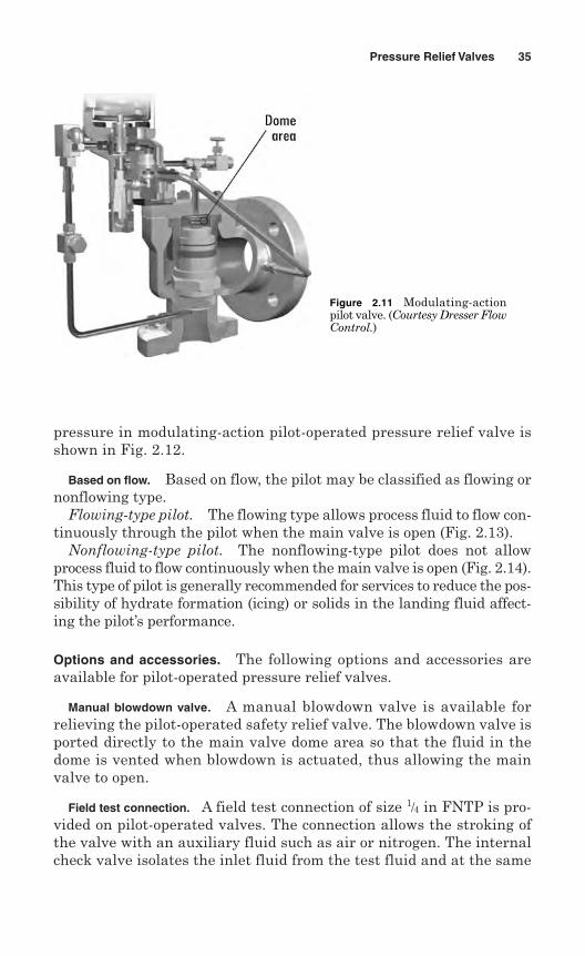
pressure in modulating-action pilot-operated pressure relief valve isshown in Fig. 2.12.
Based on flow. Based on flow, the pilot may be classified as flowing ornonflowing type.
Flowing-type pilot. The flowing type allows process fluid to flow con-tinuously through the pilot when the main valve is open (Fig. 2.13).
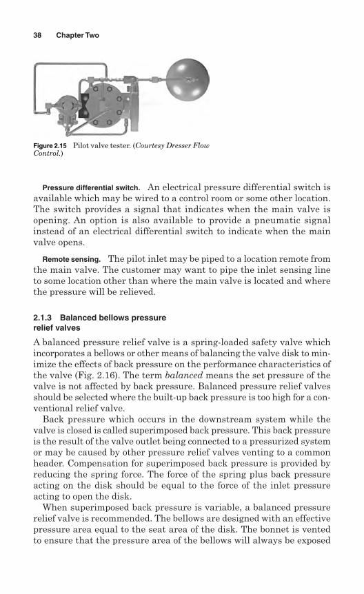
Nonflowing-type pilot. The nonflowing-type pilot does not allowprocess fluid to flow continuously when the main valve is open (Fig. 2.14).This type of pilot is generally recommended for services to reduce the pos-sibility of hydrate formation (icing) or solids in the landing fluid affect-ing the pilot’s performance.
Options and accessories. The following options and accessories areavailable for pilot-operated pressure relief valves.
Manual blowdown valve. A manual blowdown valve is available forrelieving the pilot-operated safety relief valve. The blowdown valve isported directly to the main valve dome area so that the fluid in thedome is vented when blowdown is actuated, thus allowing the mainvalve to open.
Field test connection. A field test connection of size 1/4 in FNTP is pro-vided on pilot-operated valves. The connection allows the stroking ofthe valve with an auxiliary fluid such as air or nitrogen. The internalcheck valve isolates the inlet fluid from the test fluid and at the same
Pressure Relief Valves 35
Figure 2.11 Modulating-actionpilot valve. (Courtesy Dresser FlowControl.)
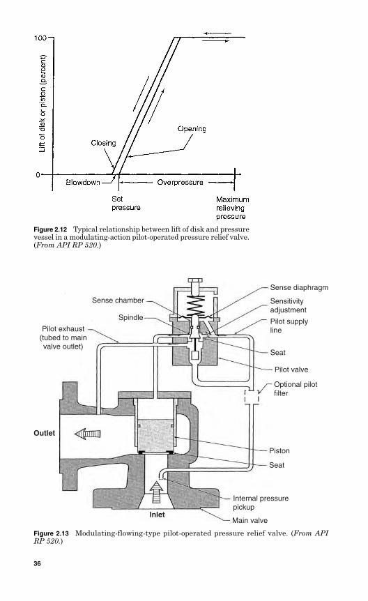
Figure 2.12 Typical relationship between lift of disk and pressurevessel in a modulating-action pilot-operated pressure relief valve.(From API RP 520.)
Sense chamber
Spindle
Pilot exhaust(tubed to mainvalve outlet)
Outlet
InletMain valve
Internal pressurepickup
Seat
Piston
Optional pilotfilter
Pilot valve
Seat
Pilot supplyline
Sensitivityadjustment
Sense diaphragm
Figure 2.13 Modulating-flowing-type pilot-operated pressure relief valve. (From APIRP 520.)
36
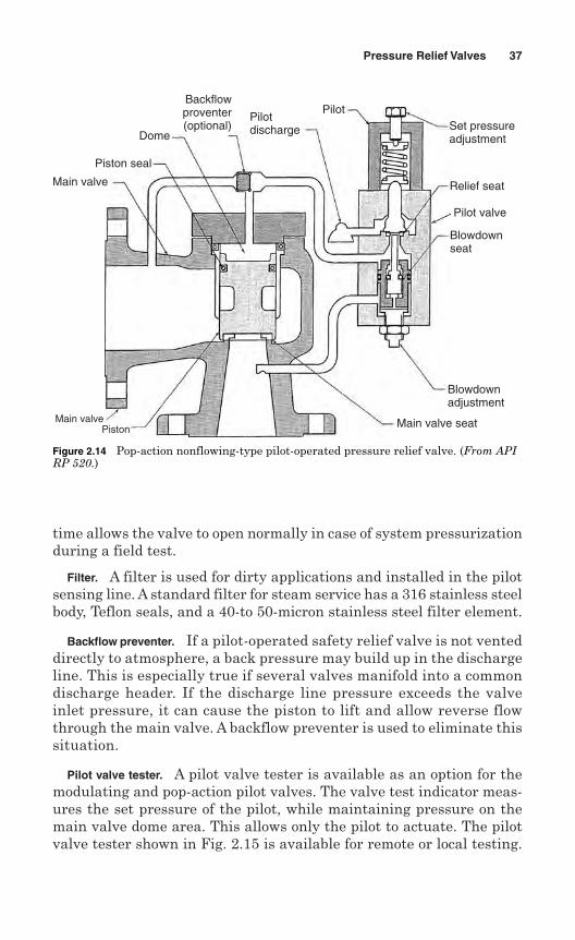
time allows the valve to open normally in case of system pressurizationduring a field test.
Filter. A filter is used for dirty applications and installed in the pilotsensing line. A standard filter for steam service has a 316 stainless steelbody, Teflon seals, and a 40-to 50-micron stainless steel filter element.
Backflow preventer. If a pilot-operated safety relief valve is not venteddirectly to atmosphere, a back pressure may build up in the dischargeline. This is especially true if several valves manifold into a commondischarge header. If the discharge line pressure exceeds the valveinlet pressure, it can cause the piston to lift and allow reverse flowthrough the main valve. A backflow preventer is used to eliminate thissituation.
Pilot valve tester. A pilot valve tester is available as an option for themodulating and pop-action pilot valves. The valve test indicator meas-ures the set pressure of the pilot, while maintaining pressure on themain valve dome area. This allows only the pilot to actuate. The pilotvalve tester shown in Fig. 2.15 is available for remote or local testing.
Pressure Relief Valves 37
Main valve
Piston seal
Dome
Backflowproventer(optional)
Pilotdischarge
PilotSet pressureadjustment
Relief seat
Pilot valve
Blowdownseat
Blowdownadjustment
Main valve seatMain valvePiston
Figure 2.14 Pop-action nonflowing-type pilot-operated pressure relief valve. (From APIRP 520.)
Pressure differential switch. An electrical pressure differential switch isavailable which may be wired to a control room or some other location.The switch provides a signal that indicates when the main valve isopening. An option is also available to provide a pneumatic signalinstead of an electrical differential switch to indicate when the mainvalve opens.
Remote sensing. The pilot inlet may be piped to a location remote fromthe main valve. The customer may want to pipe the inlet sensing lineto some location other than where the main valve is located and wherethe pressure will be relieved.
2.1.3 Balanced bellows pressurerelief valves
A balanced pressure relief valve is a spring-loaded safety valve whichincorporates a bellows or other means of balancing the valve disk to min-imize the effects of back pressure on the performance characteristics ofthe valve (Fig. 2.16). The term balanced means the set pressure of thevalve is not affected by back pressure. Balanced pressure relief valvesshould be selected where the built-up back pressure is too high for a con-ventional relief valve.
Back pressure which occurs in the downstream system while thevalve is closed is called superimposed back pressure. This back pressureis the result of the valve outlet being connected to a pressurized systemor may be caused by other pressure relief valves venting to a commonheader. Compensation for superimposed back pressure is provided byreducing the spring force. The force of the spring plus back pressureacting on the disk should be equal to the force of the inlet pressureacting to open the disk.
When superimposed back pressure is variable, a balanced pressurerelief valve is recommended. The bellows are designed with an effectivepressure area equal to the seat area of the disk. The bonnet is ventedto ensure that the pressure area of the bellows will always be exposed
38 Chapter Two
Figure 2.15 Pilot valve tester. (Courtesy Dresser FlowControl.)
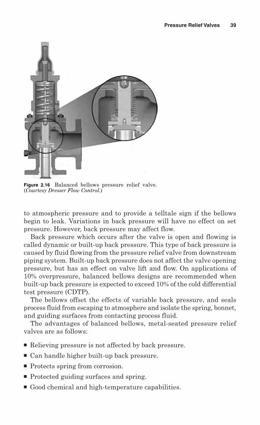
to atmospheric pressure and to provide a telltale sign if the bellowsbegin to leak. Variations in back pressure will have no effect on setpressure. However, back pressure may affect flow.
Back pressure which occurs after the valve is open and flowing iscalled dynamic or built-up back pressure. This type of back pressure iscaused by fluid flowing from the pressure relief valve from downstreampiping system. Built-up back pressure does not affect the valve openingpressure, but has an effect on valve lift and flow. On applications of10% overpressure, balanced bellows designs are recommended whenbuilt-up back pressure is expected to exceed 10% of the cold differentialtest pressure (CDTP).
The bellows offset the effects of variable back pressure, and sealsprocess fluid from escaping to atmosphere and isolate the spring, bonnet,and guiding surfaces from contacting process fluid.
The advantages of balanced bellows, metal-seated pressure reliefvalves are as follows:
Relieving pressure is not affected by back pressure. Can handle higher built-up back pressure. Protects spring from corrosion. Protected guiding surfaces and spring. Good chemical and high-temperature capabilities.
Pressure Relief Valves 39
Figure 2.16 Balanced bellows pressure relief valve.(Courtesy Dresser Flow Control.)
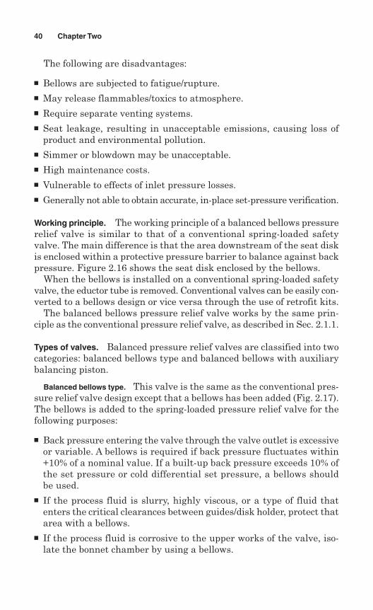
The following are disadvantages:
Bellows are subjected to fatigue/rupture. May release flammables/toxics to atmosphere. Require separate venting systems. Seat leakage, resulting in unacceptable emissions, causing loss of
product and environmental pollution. Simmer or blowdown may be unacceptable. High maintenance costs. Vulnerable to effects of inlet pressure losses. Generally not able to obtain accurate, in-place set-pressure verification.
Working principle. The working principle of a balanced bellows pressurerelief valve is similar to that of a conventional spring-loaded safetyvalve. The main difference is that the area downstream of the seat diskis enclosed within a protective pressure barrier to balance against backpressure. Figure 2.16 shows the seat disk enclosed by the bellows.
When the bellows is installed on a conventional spring-loaded safetyvalve, the eductor tube is removed. Conventional valves can be easily con-verted to a bellows design or vice versa through the use of retrofit kits.
The balanced bellows pressure relief valve works by the same prin-ciple as the conventional pressure relief valve, as described in Sec. 2.1.1.
Types of valves. Balanced pressure relief valves are classified into twocategories: balanced bellows type and balanced bellows with auxiliarybalancing piston.
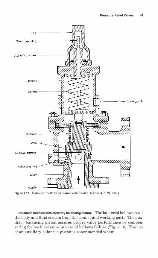
Balanced bellows type. This valve is the same as the conventional pres-sure relief valve design except that a bellows has been added (Fig. 2.17).The bellows is added to the spring-loaded pressure relief valve for thefollowing purposes:
Back pressure entering the valve through the valve outlet is excessiveor variable. A bellows is required if back pressure fluctuates within+10% of a nominal value. If a built-up back pressure exceeds 10% ofthe set pressure or cold differential set pressure, a bellows shouldbe used.
If the process fluid is slurry, highly viscous, or a type of fluid thatenters the critical clearances between guides/disk holder, protect thatarea with a bellows.
If the process fluid is corrosive to the upper works of the valve, iso-late the bonnet chamber by using a bellows.
40 Chapter Two
Balanced bellows with auxiliary balancing piston. The balanced bellows sealsthe body and fluid stream from the bonnet and working parts. The aux-iliary balancing piston assures proper valve performance by compen-sating for back pressure in case of bellows failure (Fig. 2.18). The useof an auxiliary balanced piston is recommended when:
Pressure Relief Valves 41
Figure 2.17 Balanced bellows pressure relief valve. (From API RP 520.)
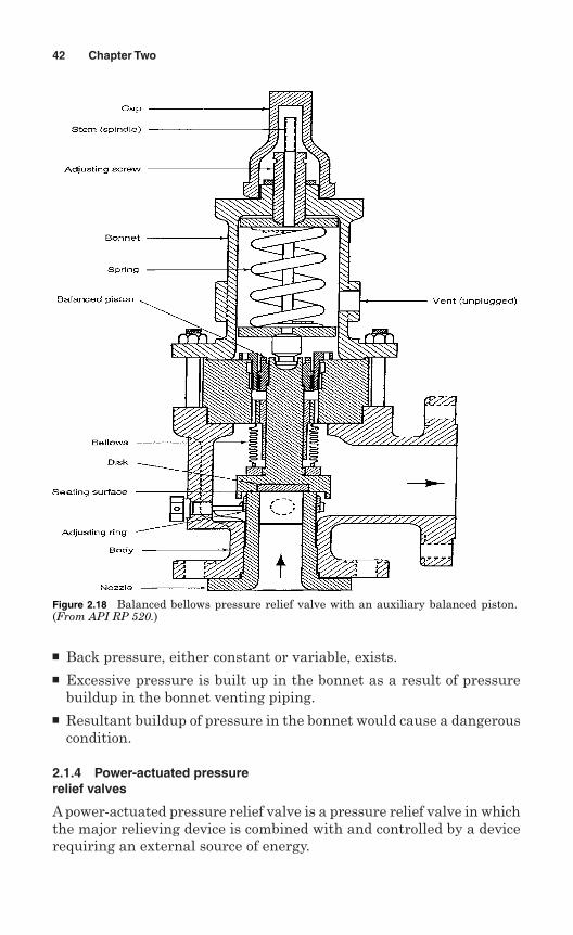
Back pressure, either constant or variable, exists. Excessive pressure is built up in the bonnet as a result of pressure
buildup in the bonnet venting piping. Resultant buildup of pressure in the bonnet would cause a dangerous
condition.
2.1.4 Power-actuated pressurerelief valves
A power-actuated pressure relief valve is a pressure relief valve in whichthe major relieving device is combined with and controlled by a devicerequiring an external source of energy.
42 Chapter Two
Figure 2.18 Balanced bellows pressure relief valve with an auxiliary balanced piston.(From API RP 520.)
The power-actuated pressure relief valve is one whose movement toopen or close is fully controlled by a source of power such as electricity,air, steam, or water (hydraulic). The valve may discharge to atmos-phere or to a container at lower pressure. The discharge capacity maybe affected by downstream conditions, and such effects should be takeninto account.
If the power-actuated pressure relieving valves act in response toother control signals, the control impulse to prevent overpressure shouldbe responsive only to pressure and should override any other controlfunction.
Power-actuated valves are used mostly for forced-flow steam gener-ators with no fixed steam or waterline. These valves are also used innuclear power plants.
2.1.5 Temperature-actuated pressure relief valves
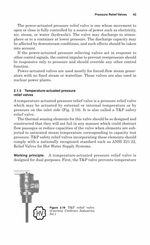
A temperature-actuated pressure relief valve is a pressure relief valvewhich may be actuated by external or internal temperature or bypressure on the inlet side (Fig. 2.19). It is also called a T&P safetyrelief valve.
The thermal sensing elements for this valve should be so designed andconstructed that they will not fail in any manner which could obstructflow passages or reduce capacities of the valve when elements are sub-jected to saturated steam temperature corresponding to capacity testpressure. T&P safety relief valves incorporating these elements shouldcomply with a nationally recognized standard such as ANSI Z21.22,Relief Valves for Hot Water Supply Systems.
Working principle. A temperature-actuated pressure relief valve isdesigned for dual purposes. First, the T&P valve prevents temperature
Pressure Relief Valves 43
Figure 2.19 T&P relief valve.(Courtesy Conbraco Industries,Inc.)
within a vessel from rising above a specified limit (generally 210°F).Second, the T&P valve also prevents pressure in the vessel from risingabove a specified value. The valve incorporates two primary controllingelements, a spring and a thermal probe.
The spring provides a force acting down on the disk, keeping it closeduntil the pressure in the vessel overcomes the spring force, then open-ing the valve and allowing fluid to escape from inside the vessel. Whenpressure is reduced as a result of this discharge, the spring causes thevalve to close and permits normal operation of the system.
On the other hand, the thermal probe senses water temperature inthe vessel, and when this temperature reaches or exceeds a specifiedtemperature, a pen or plunger within the probe pushes upward againstthe disk and causes it to open. The thermal probe accomplishes this bya waxlike substance within the probe which undergoes a phase trans-formation as a result of increasing temperature and expands whendoing so. This expansion causes the pen to push upward, dischargingfluid from the vessel. When fluid is discharged as a result of the probeoperation, a cooler supply of fluid enters into the vessel, reducing over-all temperature in the vessel to within an acceptable limit. At thispoint, the pen in the thermal probe retracts and permits the spring tocause the valve disk to reclose.
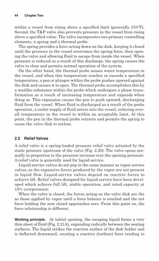
2.2 Relief Valves
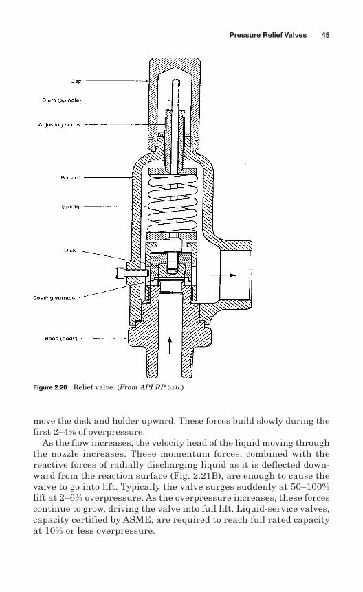
A relief valve is a spring-loaded pressure relief valve actuated by thestatic pressure upstream of the valve (Fig. 2.20). The valve opens nor-mally in proportion to the pressure increase over the opening pressure.A relief valve is generally used for liquid service.
Liquid-service valves do not pop in the same manner as vapor-servicevalves, as the expansive forces produced by the vapor are not presentin liquid flow. Liquid-service valves depend on reactive forces toachieve lift. Relief valves designed for liquid service have been devel-oped which achieve full lift, stable operation, and rated capacity at10% overpressure.
When the valve is closed, the forces acting on the valve disk are theas those applied by vapor until a force balance is reached and the netforce holding the seat closed approaches zero. From this point on, theforce relationship is different.
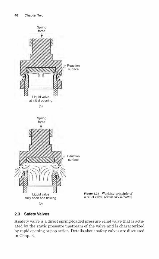
Working principle. At initial opening, the escaping liquid forms a verythin sheet of fluid (Fig. 2.21A), expanding radically between the seatingsurfaces. The liquid strikes the reaction surface of the disk holder andis deflected downward, creating a reactive (turbine) force tending to
44 Chapter Two
move the disk and holder upward. These forces build slowly during thefirst 2–4% of overpressure.
As the flow increases, the velocity head of the liquid moving throughthe nozzle increases. These momentum forces, combined with thereactive forces of radially discharging liquid as it is deflected down-ward from the reaction surface (Fig. 2.21B), are enough to cause thevalve to go into lift. Typically the valve surges suddenly at 50–100%lift at 2–6% overpressure. As the overpressure increases, these forcescontinue to grow, driving the valve into full lift. Liquid-service valves,capacity certified by ASME, are required to reach full rated capacityat 10% or less overpressure.
Pressure Relief Valves 45
Figure 2.20 Relief valve. (From API RP 520.)
2.3 Safety Valves
A safety valve is a direct spring-loaded pressure relief valve that is actu-ated by the static pressure upstream of the valve and is characterizedby rapid opening or pop action. Details about safety valves are discussedin Chap. 3.
46 Chapter Two
Springforce
Reactionsurface
Liquid valveat initial opening
(a)
Springforce
Reactionsurface
Liquid valvefully open and flowing
(b)
Figure 2.21 Working principle ofa relief valve. (From API RP 520.)
2.4 Major Components
Adjusting ring. A ring assembled to the nozzle or guide of a directspring valve, used to control the opening characteristics and/or thereseat pressure.
Adjusting screw. A screw used to adjust the set pressure or the reseatpressure of a reclosing pressure relief valve.
Balanced bellows. A bellows designed so that the effective area of thebellow is equivalent to that of the valve seat, thereby canceling outthe additive effect of back pressure.
Body. A pressure retaining or containing member of a pressure reliefdevice that supports the parts of the valve assembly and has provision(s)for connecting to the primary and/or secondary pressure source(s).
Bonnet. A component of a direct spring valve or of a pilot in a pilot-operated valve that supports the spring. It may or may not be pres-sure containing.
Cap. A component used to restrict access and/or protect the adjust-ment screw in a reclosing pressure relief device. It may or may not bea pressure containing part.
Disk. A moveable component of a pressure relief device that containsthe primary pressure when it rests against the nozzle.
Disk holder. A moveable component in a pressure relief device thatcontains the disk.
Guide. A component in a direct spring or pilot operated pressure reliefdevice used to control the lateral movement of the disk or disk holder.
Huddling chamber. The annular pressure chamber located beyondthe valve seat for the purpose of generating a popping characteristic.
Lifting device (lever). A device to open a pressure relief valve man-ually, by the application of external force to lessen the spring loadingwhich holds the valve closed. Lifting devices can be open levers orpacked levers (fully enclosed design).
Nozzle. The pressure-containing element which constitutes the inletflow passage and includes the fixed portion of the seat closure. Nozzlescan be divided into two types:- Full nozzle. A single member extending from the face of the inletflange to the valve seat.- Semi-nozzle. The lower part of the inlet throat is formed by the bodycasting and the upper part is valve seat threaded or welded into thevalve body.
Orifice. A computed area of flow for use in flow formulas to deter-mine the capacity of a pressure relief valve.
Pressure Relief Valves 47
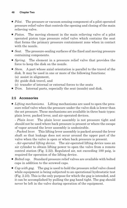
Pilot. The pressure or vacuum sensing component of a pilot operatedpressure relief valve that controls the opening and closing of the mainrelieving valve.
Piston. The moving element in the main relieving valve of a pilotoperated piston type pressure relief valve which contains the seatthat forms the primary pressure containment zone when in contactwith the nozzle.
Seat. The pressure-sealing surfaces of the fixed and moving pressurecontaining components.
Spring. The element in a pressure relief valve that provides theforce to keep the disk on the nozzle.
Stem. A part whose axial orientation is parallel to the travel of thedisk. It may be used in one or more of the following functions:(a) assist in alignment,(b) guide disk travel, and(c) transfer of internal or external forces to the seats
Trim. Internal parts, especially the seat (nozzle) and disk.
2.5 Accessories
Lifting mechanisms. Lifting mechanisms are used to open the pres-sure relief valve when the pressure under the valve disk is lower thanthe set pressure. These mechanisms are available in three basic types:plain lever, packed lever, and air-operated devices.- Plain lever. The plain lever assembly is not pressure tight andshould not be used where back pressure is present or where the escapeof vapor around the lever assembly is undesirable.- Packed lever. This lifting lever assembly is packed around the levershaft so that leakage does not occur around the upper part of thevalve when the valve is open or when back pressure is present.- Air-operated lifting device. The air-operated lifting device uses anair cylinder to obtain lifting power to open the valve from a remotecontrol station (Fig. 2.22). Regulated air, not exceeding 100 psig, isrequired for operation of the lifting device.
Bolted cap. Standard pressure relief valves are available with boltedcaps in addition to the screwed caps.
Cap with gag. The gag is used to hold the pressure relief valve closedwhile equipment is being subjected to an operational hydrostatic test(Fig. 2.23). This is the only purpose for which the gag is intended, andit can be accomplished by pulling the gag hand tight. The gag shouldnever be left in the valve during operation of the equipment.
48 Chapter Two
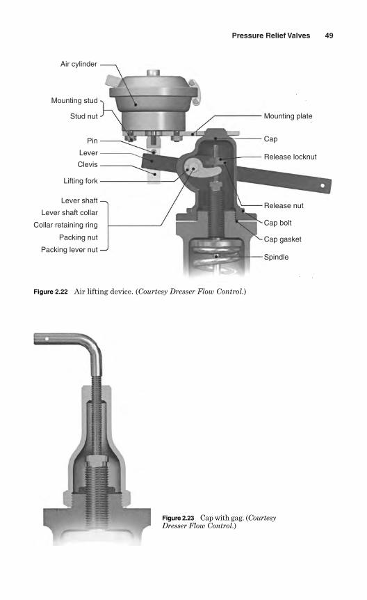
Pressure Relief Valves 49
Figure 2.23 Cap with gag. (CourtesyDresser Flow Control.)
Air cylinder
Mounting stud
Stud nut
Pin
Lever
Clevis
Lifting fork
Lever shaft
Lever shaft collar
Collar retaining ring
Packing nut
Packing lever nut
Mounting plate
Cap
Release locknut
Release nut
Cap bolt
Cap gasket
Spindle
Figure 2.22 Air lifting device. (Courtesy Dresser Flow Control.)
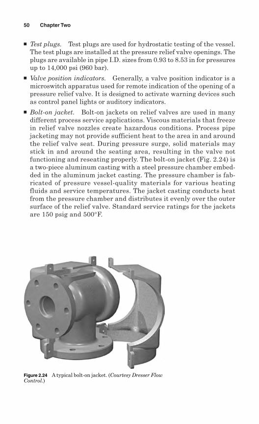
Test plugs. Test plugs are used for hydrostatic testing of the vessel.The test plugs are installed at the pressure relief valve openings. Theplugs are available in pipe I.D. sizes from 0.93 to 8.53 in for pressuresup to 14,000 psi (960 bar).
Valve position indicators. Generally, a valve position indicator is amicroswitch apparatus used for remote indication of the opening of apressure relief valve. It is designed to activate warning devices suchas control panel lights or auditory indicators.
Bolt-on jacket. Bolt-on jackets on relief valves are used in manydifferent process service applications. Viscous materials that freezein relief valve nozzles create hazardous conditions. Process pipejacketing may not provide sufficient heat to the area in and aroundthe relief valve seat. During pressure surge, solid materials maystick in and around the seating area, resulting in the valve notfunctioning and reseating properly. The bolt-on jacket (Fig. 2.24) isa two-piece aluminum casting with a steel pressure chamber embed-ded in the aluminum jacket casting. The pressure chamber is fab-ricated of pressure vessel-quality materials for various heatingfluids and service temperatures. The jacket casting conducts heatfrom the pressure chamber and distributes it evenly over the outersurface of the relief valve. Standard service ratings for the jacketsare 150 psig and 500°F.
50 Chapter Two
Figure 2.24 A typical bolt-on jacket. (Courtesy Dresser FlowControl.)
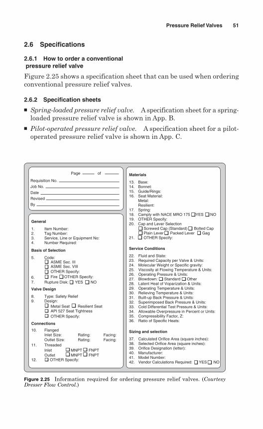
2.6 Specifications
2.6.1 How to order a conventionalpressure relief valve
Figure 2.25 shows a specification sheet that can be used when orderingconventional pressure relief valves.
2.6.2 Specification sheets
Spring-loaded pressure relief valve. A specification sheet for a spring-loaded pressure relief valve is shown in App. B.
Pilot-operated pressure relief valve. A specification sheet for a pilot-operated pressure relief valve is shown in App. C.
Pressure Relief Valves 51
Page of
Requisition No.
Job No.
Date
Revised
By
General
1. Item Number:2. Tag Number:3. Service, Line or Equipment No:4. Number Required:
Basis of Selection
5. Code:ASME Sec. IIIASME Sec. VIIIOTHER Specify:Fire OTHER Specify:6.
7. Rupture Disk: YES NO
Valve Design
8. Type: Safety Relief9. Design:
Connections
10. Flanged
Metal SeatAPI 527 Seat TightnessOTHER Specify:
Resilient Seat
Inlet Size:Outlet Size:
11. Threaded
12. OTHER Specify:
InletOutlet
MNPT FNPTMNPT FNPT
Rating:Rating:
Facing:Facing:
Materials
13. Base:14. Bonnet:15. Guide/Rings:16. Seat Material: Metal: Resilient:17. Spring:18. Camply with NACE MRO 175 YES NO19. OTHER Specify:20. Cap and Lever Selection Screwed Cap (Standard) Bolted Cap Plain Lever Packed Lever Gag21. OTHER Specify:
Sizing and selection
37. Calculated Orifice Area (square inches):38. Selected Orifice Area (square inches):39. Orifice Designation (letter):40. Manufacturer:41. Model Number:42. Vendor Calculations Required: YES NO
Service Conditions
22. Fluid and State:23. Required Capacity per Valve & Units:24. Molecular Weight or Specific gravity:25. Viscosity at Flowing Temperature & Units:26. Operating Pressure & Units:27. Blowdown: Standard Other28. Latent Heat of Voparization & Units:29. Operating Temperature & Units:30. Relieving Temperature & Units:31. Built-up Back Pressure & Units:32. Superimposed Back Pressure & Units:33. Cold Differential Test Pressure & Units:34. Allowable Overpressure in Percent or Units:35. Compressibility Factor, Z:36. Ratio of Specific Heats:
Figure 2.25 Information required for ordering pressure relief valves. (CourtesyDresser Flow Control.)

This page intentionally left blank
Chapter
3Safety Valves
The principal device used to prevent overpressure in steam plants is thesafety valve. The safety valve operates by releasing a volume of fluid fromwithin the plant when a predetermined maximum pressure is reached,thereby reducing the excess pressure in a safe manner. As the safety valveis the only remaining mechanical device to prevent catastrophic failureunder overpressure conditions, it is most important that any such deviceis capable of operating at all times and under all possible conditions.
Safety valves are installed wherever the maximum allowable workingpressure (MAWP) of a system or pressure-containing vessel is likely tobe exceeded. Safety valves are typically used for boiler overpressure pro-tection and other applications such as downstream of pressure-reducingcontrols. Although their primary role is for safety, safety valves are alsoused in process operations to prevent product damage due to excesspressure.
A wide range of different safety valves is available for many differentapplications and performance criteria. Furthermore, various designsare required to meet the numerous national standards that govern theuse of safety valves.
3.1 Working Principle
A safety valve is a pressure relief valve, and its working principle is sim-ilar to that of a conventional pressure relief valve. A safety valve isactuated by inlet static pressure and characterized by rapid opening orpop action. A sectional view of a safety valve is shown in Fig. 3.1.
Lifting. When the inlet static pressure rises above the set pressure,the valve begins to lift off its seat. As soon as the spring starts to com-press, the spring force increases. That means the pressure is required
53
Copyright © 2006 by The McGraw-Hill Companies, Inc. Click here for terms of use.
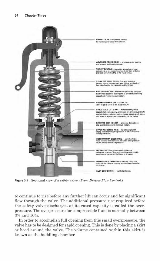
to continue to rise before any further lift can occur and for significantflow through the valve. The additional pressure rise required beforethe safety valve discharges at its rated capacity is called the over-pressure. The overpressure for compressible fluid is normally between3% and 10%.
In order to accomplish full opening from this small overpressure, thevalve has to be designed for rapid opening. This is done by placing a skirtor hood around the valve. The volume contained within this skirt isknown as the huddling chamber.
54 Chapter Three
Figure 3.1 Sectional view of a safety valve. (From Dresser Flow Control.)
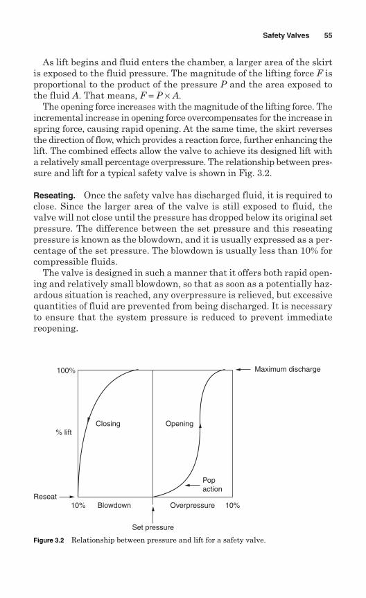
As lift begins and fluid enters the chamber, a larger area of the skirtis exposed to the fluid pressure. The magnitude of the lifting force F isproportional to the product of the pressure P and the area exposed tothe fluid A. That means, F = P × A.
The opening force increases with the magnitude of the lifting force. Theincremental increase in opening force overcompensates for the increase inspring force, causing rapid opening. At the same time, the skirt reversesthe direction of flow, which provides a reaction force, further enhancing thelift. The combined effects allow the valve to achieve its designed lift witha relatively small percentage overpressure. The relationship between pres-sure and lift for a typical safety valve is shown in Fig. 3.2.
Reseating. Once the safety valve has discharged fluid, it is required toclose. Since the larger area of the valve is still exposed to fluid, thevalve will not close until the pressure has dropped below its original setpressure. The difference between the set pressure and this reseatingpressure is known as the blowdown, and it is usually expressed as a per-centage of the set pressure. The blowdown is usually less than 10% forcompressible fluids.
The valve is designed in such a manner that it offers both rapid open-ing and relatively small blowdown, so that as soon as a potentially haz-ardous situation is reached, any overpressure is relieved, but excessivequantities of fluid are prevented from being discharged. It is necessaryto ensure that the system pressure is reduced to prevent immediatereopening.
Safety Valves 55
10% Blowdown
Set pressure
Overpressure 10%Reseat
% lift
100%
Popaction
Closing Opening
Maximum discharge
Figure 3.2 Relationship between pressure and lift for a safety valve.
The blowdown rings on the safety valves are used to make fine adjust-ments to the overpressure and blowdown values. The upper adjustingring is usually factory set and if it is adjusted, this takes out the man-ufacturing tolerances which affect geometry of the huddling chamber.The lower adjusting ring is also factory set but can be adjusted undercertain conditions. When the lower adjusting ring is adjusted to its topposition, the valve pops rapidly, minimizing the overpressure, andrequires a greater blowdown before the valve reseats. When the loweradjusting ring is adjusted to its lower position, a greater overpressureis required before the valve is fully open and the blowdown value isreduced.
3.2 Classification of Safety Valves
Many types of safety valves are used in modern applications. Thesesafety valves are classified based on:
Actuation Lift Seat design Lever Bonnet
3.2.1 Classification based on actuation
Based on type of actuation, safety valves are classified as dead-weightsafety valves and pop-action safety valves.
Dead-weight safety valves. Although dead-weight safety valves have ingeneral been superceded by spring-loaded safety valves, the dead weightvariety (Fig. 3.3) is still sometimes used for low-pressure applications.The closing force of this safety valve is provided by a weight rather thana spring. As the closing force is provided by a weight, it remains constantand once the set pressure is reached, the safety valve opens fully.
Pop action safety valves. The pop-action safety valve is the standard orconventional safety valve. It is actuated by inlet static pressure andcharacterized by rapid opening or pop action. This type of safety valveis a simple, basic spring-loaded, and self-acting device that providesoverpressure protection (Fig. 3.4).
The basic elements of the design consist of a right-angle-pattern valvebody with the valve inlet connection, or nozzle, mounted on the pressure-containing system. The outlet connection may be screwed or flanged for
56 Chapter Three
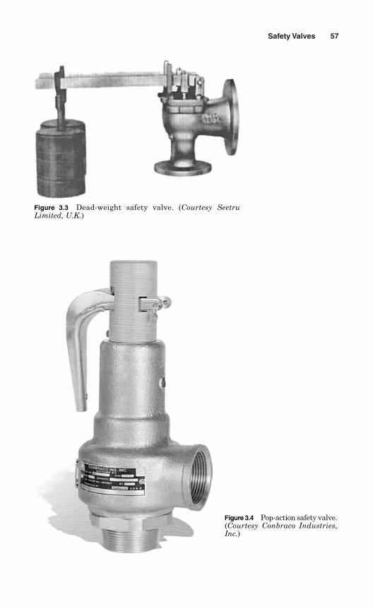
Safety Valves 57
Figure 3.3 Dead-weight safety valve. (Courtesy SeetruLimited, U.K.)
Figure 3.4 Pop-action safety valve.(Courtesy Conbraco Industries,Inc.)
connection to a pipe discharge system. In some applications, such as com-pressed air systems, the safety valve does not have an outlet connectionand the air is vented directly to the atmosphere.
The valve is held against the nozzle seat by the spring, which is housedin an open or closed spring housing arrangement (bonnet) mounted onthe top of the body. The disks in rapid-opening (pop-type) safety valvesare surrounded by a huddling chamber, which helps to produce the rapid-opening characteristic.
The closing force on the valve is provided by a spring, typically madefrom carbon steel. The amount of compression on the spring is usuallyadjustable, using the spring adjuster, to change the pressure at whichthe valve is lifted off its seat.
3.2.2 Classification based on lift
Safety valves may be classified based on lift. The term lift refers to theamount of travel the valve undergoes as it moves from its closed posi-tion to the position required to produce the certified discharge capacity.
Safety valves may be classified as full lift, high lift, and low lift basedon the amount of lift, which affects the discharge capacity of the valve.
Full-lift safety valves. A full-lift safety valve is a safety valve in whichthe valve lifts sufficiently so that the curtain area no longer influencesthe discharge area. This occurs when the valve lifts a distance of atleast a quarter of the bore diameter. That is, the discharge area, andtherefore the capacity of the valve, is determined by the bore area.
Full-lift safety valves are considered the best choice for general steamapplications.
High-lift safety valves. A high-lift safety valve is a safety valve in whichthe valve lifts a distance of at least 1/12th of the bore diameter. Thismeans that the curtain area, and ultimately the position of the valve,determine the discharge area. The discharge capacity of a high-lift valveis significantly lower than that of a full-lift valve. For a given dischargecapacity, a full-lift valve has smaller size than a corresponding high-liftvalve.
High-lift safety valves are used on compressible fluids, where theiraction is more proportional.
Low-lift safety valves. A low-lift safety valve is a safety valve in whichthe valve lifts a distance of 1/24th of the bore diameter. The dischargearea is determined by the position of the valve. Since the valve has asmall lift, the capacity of a low-lift safety valve is much lower than thatof full- or high-lift valves.
58 Chapter Three
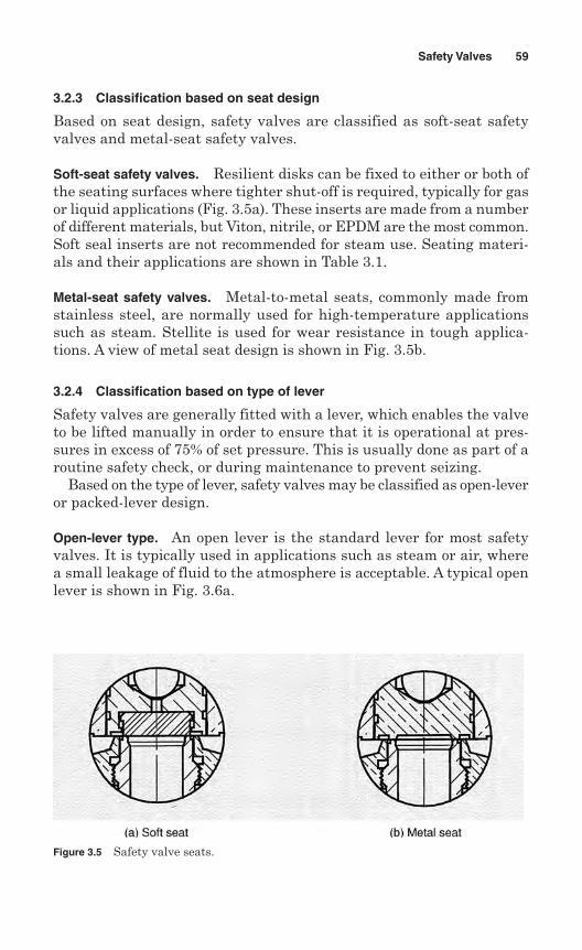
3.2.3 Classification based on seat design
Based on seat design, safety valves are classified as soft-seat safetyvalves and metal-seat safety valves.
Soft-seat safety valves. Resilient disks can be fixed to either or both ofthe seating surfaces where tighter shut-off is required, typically for gasor liquid applications (Fig. 3.5a). These inserts are made from a numberof different materials, but Viton, nitrile, or EPDM are the most common.Soft seal inserts are not recommended for steam use. Seating materi-als and their applications are shown in Table 3.1.
Metal-seat safety valves. Metal-to-metal seats, commonly made fromstainless steel, are normally used for high-temperature applicationssuch as steam. Stellite is used for wear resistance in tough applica-tions. A view of metal seat design is shown in Fig. 3.5b.
3.2.4 Classification based on type of lever
Safety valves are generally fitted with a lever, which enables the valveto be lifted manually in order to ensure that it is operational at pres-sures in excess of 75% of set pressure. This is usually done as part of aroutine safety check, or during maintenance to prevent seizing.
Based on the type of lever, safety valves may be classified as open-leveror packed-lever design.
Open-lever type. An open lever is the standard lever for most safetyvalves. It is typically used in applications such as steam or air, wherea small leakage of fluid to the atmosphere is acceptable. A typical openlever is shown in Fig. 3.6a.
Safety Valves 59
Figure 3.5 Safety valve seats.
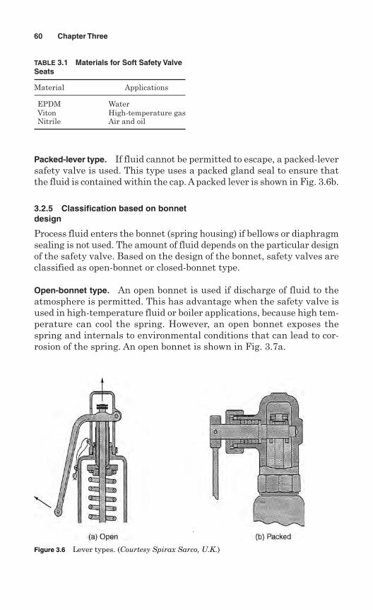
Packed-lever type. If fluid cannot be permitted to escape, a packed-leversafety valve is used. This type uses a packed gland seal to ensure thatthe fluid is contained within the cap. A packed lever is shown in Fig. 3.6b.
3.2.5 Classification based on bonnetdesign
Process fluid enters the bonnet (spring housing) if bellows or diaphragmsealing is not used. The amount of fluid depends on the particular designof the safety valve. Based on the design of the bonnet, safety valves areclassified as open-bonnet or closed-bonnet type.
Open-bonnet type. An open bonnet is used if discharge of fluid to theatmosphere is permitted. This has advantage when the safety valve isused in high-temperature fluid or boiler applications, because high tem-perature can cool the spring. However, an open bonnet exposes thespring and internals to environmental conditions that can lead to cor-rosion of the spring. An open bonnet is shown in Fig. 3.7a.
60 Chapter Three
TABLE 3.1 Materials for Soft Safety ValveSeats
Material Applications
EPDM WaterViton High-temperature gas Nitrile Air and oil
Figure 3.6 Lever types. (Courtesy Spirax Sarco, U.K.)
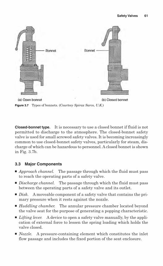
Closed-bonnet type. It is necessary to use a closed bonnet if fluid is notpermitted to discharge to the atmosphere. The closed-bonnet safetyvalve is used for small screwed safety valves. It is becoming increasinglycommon to use closed-bonnet safety valves, particularly for steam, dis-charge of which can be hazardous to personnel. A closed bonnet is shownin Fig. 3.7b.
3.3 Major Components
Approach channel. The passage through which the fluid must passto reach the operating parts of a safety valve.
Discharge channel. The passage through which the fluid must passbetween the operating parts of a safety valve and its outlet.
Disk. A moveable component of a safety valve that contains the pri-mary pressure when it rests against the nozzle.
Huddling chamber. The annular pressure chamber located beyondthe valve seat for the purpose of generating a popping characteristic.
Lifting lever. A device to open a safety valve manually, by the appli-cation of external force to lessen the spring loading which holds thevalve closed.
Nozzle. A pressure-containing element which constitutes the inletflow passage and includes the fixed portion of the seat enclosure.
Safety Valves 61
Figure 3.7 Types of bonnets. (Courtesy Spirax Sarco, U.K.)
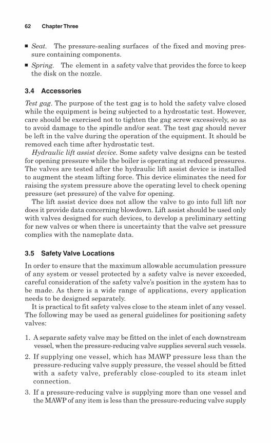
Seat. The pressure-sealing surfaces of the fixed and moving pres-sure containing components.
Spring. The element in a safety valve that provides the force to keepthe disk on the nozzle.
3.4 Accessories
Test gag. The purpose of the test gag is to hold the safety valve closedwhile the equipment is being subjected to a hydrostatic test. However,care should be exercised not to tighten the gag screw excessively, so asto avoid damage to the spindle and/or seat. The test gag should neverbe left in the valve during the operation of the equipment. It should beremoved each time after hydrostatic test.
Hydraulic lift assist device. Some safety valve designs can be testedfor opening pressure while the boiler is operating at reduced pressures.The valves are tested after the hydraulic lift assist device is installedto augment the steam lifting force. This device eliminates the need forraising the system pressure above the operating level to check openingpressure (set pressure) of the valve for opening.
The lift assist device does not allow the valve to go into full lift nordoes it provide data concerning blowdown. Lift assist should be used onlywith valves designed for such devices, to develop a preliminary settingfor new valves or when there is uncertainty that the valve set pressurecomplies with the nameplate data.
3.5 Safety Valve Locations
In order to ensure that the maximum allowable accumulation pressureof any system or vessel protected by a safety valve is never exceeded,careful consideration of the safety valve’s position in the system has tobe made. As there is a wide range of applications, every applicationneeds to be designed separately.
It is practical to fit safety valves close to the steam inlet of any vessel.The following may be used as general guidelines for positioning safetyvalves:
1. A separate safety valve may be fitted on the inlet of each downstreamvessel, when the pressure-reducing valve supplies several such vessels.
2. If supplying one vessel, which has MAWP pressure less than thepressure-reducing valve supply pressure, the vessel should be fittedwith a safety valve, preferably close-coupled to its steam inletconnection.
3. If a pressure-reducing valve is supplying more than one vessel andthe MAWP of any item is less than the pressure-reducing valve supply
62 Chapter Three
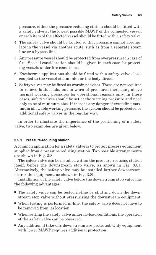
pressure, either the pressure-reducing station should be fitted witha safety valve at the lowest possible MAWP of the connected vessel,or each item of the affected vessel should be fitted with a safety valve.
4. The safety valve should be located so that pressure cannot accumu-late in the vessel via another route, such as from a separate steamline or a bypass line.
5. Any pressure vessel should be protected from overpressure in case offire. Special consideration should be given in each case for protect-ing vessels under fire conditions.
6. Exothermic applications should be fitted with a safety valve close-coupled to the vessel steam inlet or the body direct.
7. Safety valves may be fitted as warning devices. These are not requiredto relieve fault loads, but to warn of pressures increasing abovenormal working pressures for operational reasons only. In thesecases, safety valves should be set at the warning pressure and needonly to be of minimum size. If there is any danger of exceeding max-imum allowable working pressure, the system should be protected byadditional safety valves in the regular way.
In order to illustrate the importance of the positioning of a safetyvalve, two examples are given below.
3.5.1 Pressure-reducing station
A common application for a safety valve is to protect process equipmentsupplied from a pressure-reducing station. Two possible arrangementsare shown in Fig. 3.8.
The safety valve can be installed within the pressure-reducing stationitself, before the downstream stop valve, as shown in Fig. 3.8a.Alternatively, the safety valve may be installed farther downstream,nearer the equipment, as shown in Fig. 3.8b.
Installation of the safety valve before the downstream stop valve hasthe following advantages:
The safety valve can be tested in-line by shutting down the down-stream stop valve without pressurizing the downstream equipment.
When testing is performed in-line, the safety valve does not have tobe removed from its location.
When setting the safety valve under no-load conditions, the operationof the safety valve can be observed.
Any additional take-offs downstream are protected. Only equipmentwith lower MAWP requires additional protection.
Safety Valves 63
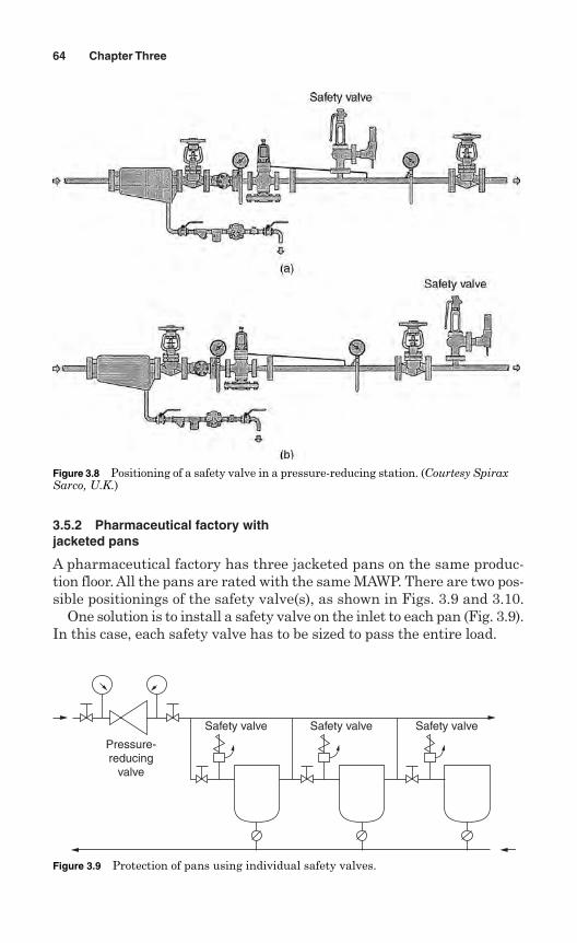
3.5.2 Pharmaceutical factory withjacketed pans
A pharmaceutical factory has three jacketed pans on the same produc-tion floor. All the pans are rated with the same MAWP. There are two pos-sible positionings of the safety valve(s), as shown in Figs. 3.9 and 3.10.
One solution is to install a safety valve on the inlet to each pan (Fig. 3.9).In this case, each safety valve has to be sized to pass the entire load.
64 Chapter Three
Figure 3.8 Positioning of a safety valve in a pressure-reducing station. (Courtesy SpiraxSarco, U.K.)
Safety valve
Pressure-reducing
valve
Safety valve Safety valve
Figure 3.9 Protection of pans using individual safety valves.
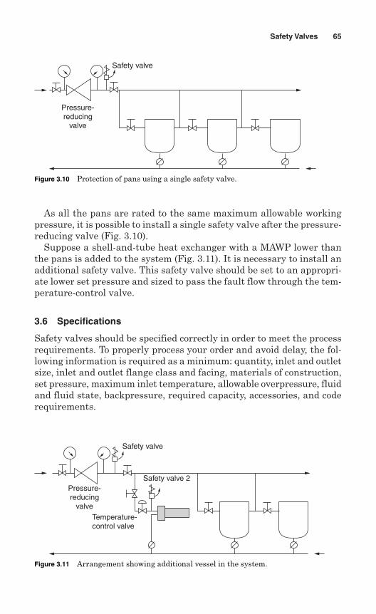
As all the pans are rated to the same maximum allowable workingpressure, it is possible to install a single safety valve after the pressure-reducing valve (Fig. 3.10).
Suppose a shell-and-tube heat exchanger with a MAWP lower thanthe pans is added to the system (Fig. 3.11). It is necessary to install anadditional safety valve. This safety valve should be set to an appropri-ate lower set pressure and sized to pass the fault flow through the tem-perature-control valve.
3.6 Specifications
Safety valves should be specified correctly in order to meet the processrequirements. To properly process your order and avoid delay, the fol-lowing information is required as a minimum: quantity, inlet and outletsize, inlet and outlet flange class and facing, materials of construction,set pressure, maximum inlet temperature, allowable overpressure, fluidand fluid state, backpressure, required capacity, accessories, and coderequirements.
Safety Valves 65
Safety valve
Pressure-reducing
valve
Figure 3.10 Protection of pans using a single safety valve.
Safety valve
Safety valve 2Pressure-reducing
valveTemperature-control valve
Figure 3.11 Arrangement showing additional vessel in the system.
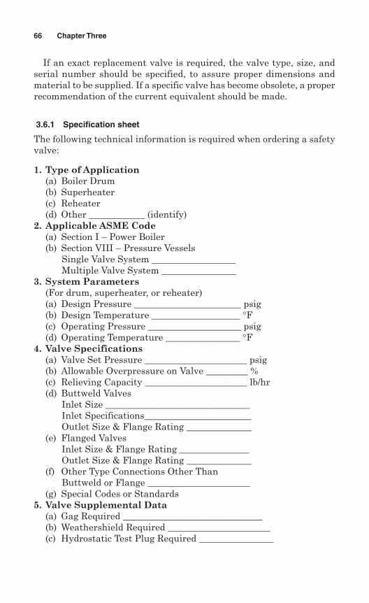
If an exact replacement valve is required, the valve type, size, andserial number should be specified, to assure proper dimensions andmaterial to be supplied. If a specific valve has become obsolete, a properrecommendation of the current equivalent should be made.
3.6.1 Specification sheet
The following technical information is required when ordering a safetyvalve:
1. Type of Application(a) Boiler Drum(b) Superheater(c) Reheater(d) Other ____________ (identify)
2. Applicable ASME Code(a) Section I – Power Boiler(b) Section VIII – Pressure Vessels
Single Valve System __________________Multiple Valve System ________________
3. System Parameters(For drum, superheater, or reheater)(a) Design Pressure _______________________ psig(b) Design Temperature ___________________ °F(c) Operating Pressure ____________________ psig(d) Operating Temperature ________________ °F
4. Valve Specifications(a) Valve Set Pressure ______________________ psig(b) Allowable Overpressure on Valve _________ %(c) Relieving Capacity ______________________ lb/hr(d) Buttweld Valves
Inlet Size _______________________________Inlet Specifications_______________________Outlet Size & Flange Rating ______________
(e) Flanged ValvesInlet Size & Flange Rating _______________Outlet Size & Flange Rating ______________
(f) Other Type Connections Other ThanButtweld or Flange ______________________
(g) Special Codes or Standards5. Valve Supplemental Data
(a) Gag Required ______________________________(b) Weathershield Required ______________________(c) Hydrostatic Test Plug Required ________________
66 Chapter Three
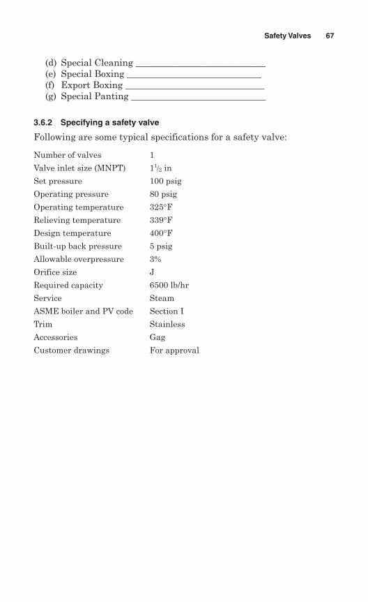
(d) Special Cleaning ____________________________(e) Special Boxing _____________________________(f) Export Boxing ______________________________(g) Special Panting _____________________________
3.6.2 Specifying a safety valve
Following are some typical specifications for a safety valve:
Number of valves 1
Valve inlet size (MNPT) 11/2 in
Set pressure 100 psig
Operating pressure 80 psig
Operating temperature 325°FRelieving temperature 339°FDesign temperature 400°FBuilt-up back pressure 5 psig
Allowable overpressure 3%
Orifice size J
Required capacity 6500 lb/hr
Service Steam
ASME boiler and PV code Section I
Trim Stainless
Accessories Gag
Customer drawings For approval
Safety Valves 67

This page intentionally left blank
Chapter
4Rupture Disks
A rupture disk is a nonreclosing precision relief device designed to rup-ture at a predetermined pressure and temperature. Rupture disks areused where instantaneous and full opening of a pressure relief deviceis required. These devices are used to protect vessels, piping, and otherpressurized systems from excessive pressure and/or vacuum.
Rupture disks may be used where “zero” leakage is required of a pres-sure relief device. These devices provide overprotection to a system whichmay be subject to excessive pressure by malfunction of mechanical equip-ment, runway chemical reaction, and external or internal fires.
A rupture disk has no moving parts, and is a simple, reliable, andfaster-acting device than other pressure relief devices. Rupture disksreact quickly to relieve some types of pressure spikes.
Rupture disks have the following advantages when compared withpressure relief valves:
Reduced emissions—no simmering or leakage before bursting Provide both overpressure protection and depressuring Protect against rapid pressure rise caused by heat-exchanger tube
ruptures Less expensive way to provide corrosion resistance Provide secondary protection for lower-probability contingencies
requiring large relief areas Fewer tendencies to foul or plug Absolute tightness when disk is intact Available in exotic materials Minimum space required
69
Copyright © 2006 by The McGraw-Hill Companies, Inc. Click here for terms of use.
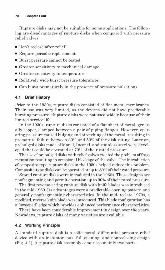
Rupture disks may not be suitable for some applications. The follow-ing are disadvantages of rupture disks when compared with pressurerelief valves:
Don’t reclose after relief Require periodic replacement Burst pressure cannot be tested Greater sensitivity to mechanical damage Greater sensitivity to temperature Relatively wide burst pressure tolerances Can burst prematurely in the presence of pressure pulsations
4.1 Brief History
Prior to the 1930s, rupture disks consisted of flat metal membranes.Their use was very limited, as the devices did not have predictablebursting pressure. Rupture disks were not used widely because of theirlimited service life.
In the 1930s, rupture disks consisted of a flat sheet of metal, gener-ally copper, clamped between a pair of piping flanges. However, oper-ating pressure caused bulging and stretching of the metal, resulting inpremature failure between 30% and 50% of the disk rating. Later on,prebulged disks made of Monel, Inconel, and stainless steel were devel-oped that could be operated at 70% of their rated pressure.
The use of prebulged disks with relief valves created the problem of frag-mentation resulting in occasional blockage of the valve. The introductionof composite-type rupture disks in the 1950s helped reduce this problem.Composite-type disks can be operated at up to 80% of their rated pressure.
Scored rupture disks were introduced in the 1960s. These designs arenonfragmenting and permit operation up to 90% of their rated pressure.
The first reverse-acting rupture disk with knife blades was introducedin the mid-1960. Its advantages were a predictable opening pattern andgenerally nonfragmenting characteristics. In the mid- to late 1970s, amodified, reverse knife blade was introduced. This blade configuration hasa “swooped” edge which provides enhanced performance characteristics.
There have been considerable improvement in design over the years.Nowadays, rupture disks of many varieties are available.
4.2 Working Principle
A standard rupture disk is a solid metal, differential pressure reliefdevice with an instantaneous, full-opening, and nonreclosing design(Fig. 4.1). A rupture disk assembly comprises mainly two parts:
70 Chapter Four
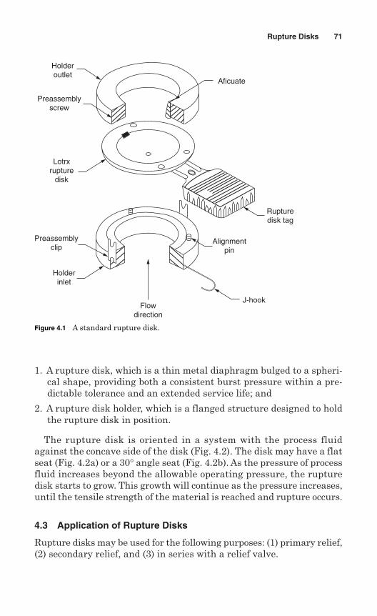
1. A rupture disk, which is a thin metal diaphragm bulged to a spheri-cal shape, providing both a consistent burst pressure within a pre-dictable tolerance and an extended service life; and
2. A rupture disk holder, which is a flanged structure designed to holdthe rupture disk in position.
The rupture disk is oriented in a system with the process fluidagainst the concave side of the disk (Fig. 4.2). The disk may have a flatseat (Fig. 4.2a) or a 30° angle seat (Fig. 4.2b). As the pressure of processfluid increases beyond the allowable operating pressure, the rupturedisk starts to grow. This growth will continue as the pressure increases,until the tensile strength of the material is reached and rupture occurs.
4.3 Application of Rupture Disks
Rupture disks may be used for the following purposes: (1) primary relief,(2) secondary relief, and (3) in series with a relief valve.
Rupture Disks 71
Lotrxrupture
disk
Holderoutlet
Preassemblyscrew
Preassemblyclip
Holderinlet
Flowdirection
J-hook
Alignmentpin
Rupturedisk tag
Aficuate
Figure 4.1 A standard rupture disk.
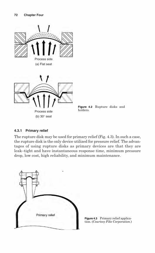
4.3.1 Primary relief
The rupture disk may be used for primary relief (Fig. 4.3). In such a case,the rupture disk is the only device utilized for pressure relief. The advan-tages of using rupture disks as primary devices are that they areleak–tight and have instantaneous response time, minimum pressuredrop, low cost, high reliability, and minimum maintenance.
72 Chapter Four
(b) 30° seat
(a) Flat seat
Process side
Process side
Figure 4.2 Rupture disks andholders.
Figure 4.3 Primary relief applica-tion. (Courtesy Fike Corporation.)
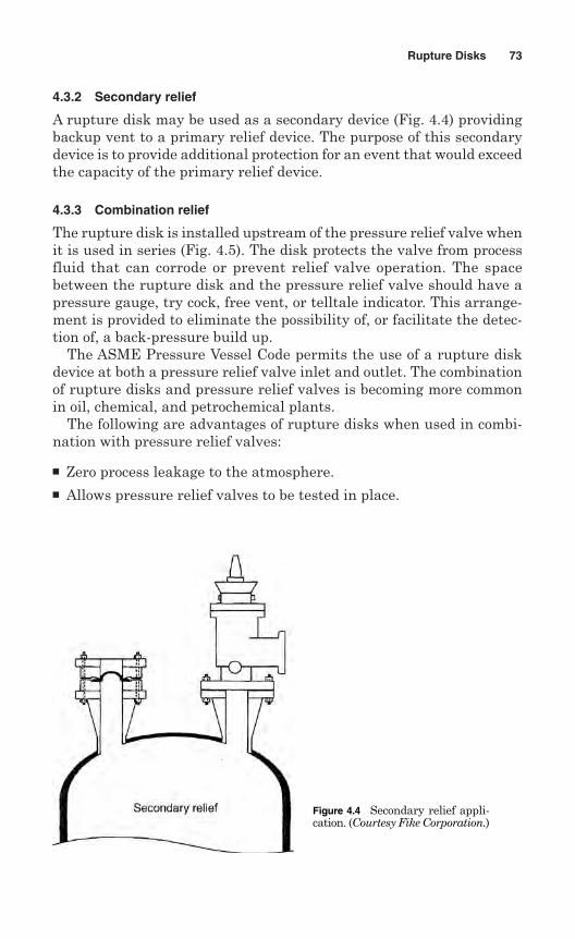
4.3.2 Secondary relief
A rupture disk may be used as a secondary device (Fig. 4.4) providingbackup vent to a primary relief device. The purpose of this secondarydevice is to provide additional protection for an event that would exceedthe capacity of the primary relief device.
4.3.3 Combination relief
The rupture disk is installed upstream of the pressure relief valve whenit is used in series (Fig. 4.5). The disk protects the valve from processfluid that can corrode or prevent relief valve operation. The spacebetween the rupture disk and the pressure relief valve should have apressure gauge, try cock, free vent, or telltale indicator. This arrange-ment is provided to eliminate the possibility of, or facilitate the detec-tion of, a back-pressure build up.
The ASME Pressure Vessel Code permits the use of a rupture diskdevice at both a pressure relief valve inlet and outlet. The combinationof rupture disks and pressure relief valves is becoming more commonin oil, chemical, and petrochemical plants.
The following are advantages of rupture disks when used in combi-nation with pressure relief valves:
Zero process leakage to the atmosphere. Allows pressure relief valves to be tested in place.
Rupture Disks 73
Figure 4.4 Secondary relief appli-cation. (Courtesy Fike Corporation.)
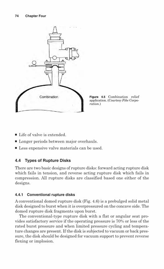
Life of valve is extended. Longer periods between major overhauls. Less expensive valve materials can be used.
4.4 Types of Rupture Disks
There are two basic designs of rupture disks: forward acting rupture diskwhich fails in tension, and reverse acting rupture disk which fails incompression. All rupture disks are classified based one either of thedesigns.
4.4.1 Conventional rupture disks
A conventional domed rupture disk (Fig. 4.6) is a prebulged solid metaldisk designed to burst when it is overpressured on the concave side. Thedomed rupture disk fragments upon burst.
The conventional-type rupture disk with a flat or angular seat pro-vides satisfactory service if the operating pressure is 70% or less of therated burst pressure and when limited pressure cycling and tempera-ture changes are present. If the disk is subjected to vacuum or back pres-sure, the disk should be designed for vacuum support to prevent reverseflexing or implosion.
74 Chapter Four
Figure 4.5 Combination reliefapplication. (Courtesy Fike Corpo-ration.)
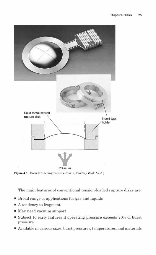
The main features of conventional tension-loaded rupture disks are:
Broad range of applications for gas and liquids A tendency to fragment May need vacuum support Subject to early failures if operating pressure exceeds 70% of burst
pressure Available in various sizes, burst pressures, temperatures, and materials
Rupture Disks 75
Figure 4.6 Forward-acting rupture disk. (Courtesy Zook USA.)
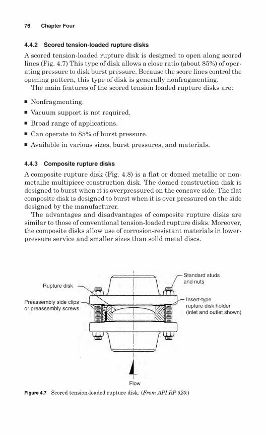
4.4.2 Scored tension-loaded rupture disks
A scored tension-loaded rupture disk is designed to open along scoredlines (Fig. 4.7) This type of disk allows a close ratio (about 85%) of oper-ating pressure to disk burst pressure. Because the score lines control theopening pattern, this type of disk is generally nonfragmenting.
The main features of the scored tension loaded rupture disks are:
Nonfragmenting. Vacuum support is not required. Broad range of applications. Can operate to 85% of burst pressure. Available in various sizes, burst pressures, and materials.
4.4.3 Composite rupture disks
A composite rupture disk (Fig. 4.8) is a flat or domed metallic or non-metallic multipiece construction disk. The domed construction disk isdesigned to burst when it is overpressured on the concave side. The flatcomposite disk is designed to burst when it is over pressured on the sidedesigned by the manufacturer.
The advantages and disadvantages of composite rupture disks aresimilar to those of conventional tension-loaded rupture disks. Moreover,the composite disks allow use of corrosion-resistant materials in lower-pressure service and smaller sizes than solid metal discs.
76 Chapter Four
Rupture disk
Preassembly side clipsor preassembly screws
Flow
Standard studsand nuts
Insert-typerupture disk holder(inlet and outlet shown)
Figure 4.7 Scored tension-loaded rupture disk. (From API RP 520.)
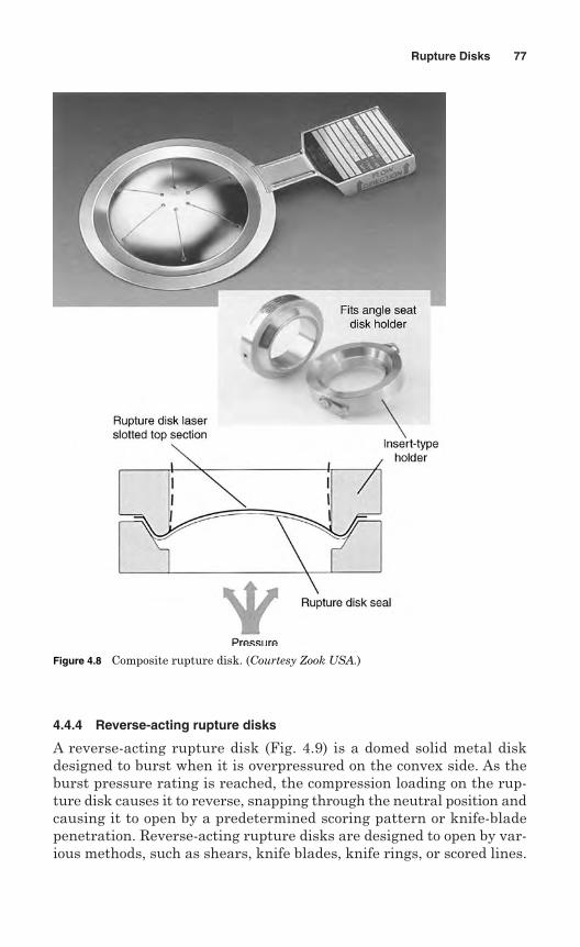
4.4.4 Reverse-acting rupture disks
A reverse-acting rupture disk (Fig. 4.9) is a domed solid metal diskdesigned to burst when it is overpressured on the convex side. As theburst pressure rating is reached, the compression loading on the rup-ture disk causes it to reverse, snapping through the neutral position andcausing it to open by a predetermined scoring pattern or knife-bladepenetration. Reverse-acting rupture disks are designed to open by var-ious methods, such as shears, knife blades, knife rings, or scored lines.
Rupture Disks 77
Figure 4.8 Composite rupture disk. (Courtesy Zook USA.)
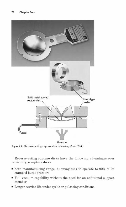
Reverse-acting rupture disks have the following advantages overtension-type rupture disks:
Zero manufacturing range, allowing disk to operate to 90% of itsstamped burst pressure
Full vacuum capability without the need for an additional supportmember
Longer service life under cyclic or pulsating conditions
78 Chapter Four
Figure 4.9 Reverse-acting rupture disk. (Courtesy Zook USA.)
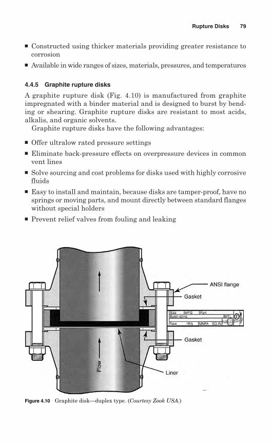
Constructed using thicker materials providing greater resistance tocorrosion
Available in wide ranges of sizes, materials, pressures, and temperatures
4.4.5 Graphite rupture disks
A graphite rupture disk (Fig. 4.10) is manufactured from graphiteimpregnated with a binder material and is designed to burst by bend-ing or shearing. Graphite rupture disks are resistant to most acids,alkalis, and organic solvents.
Graphite rupture disks have the following advantages:
Offer ultralow rated pressure settings Eliminate back-pressure effects on overpressure devices in common
vent lines Solve sourcing and cost problems for disks used with highly corrosive
fluids Easy to install and maintain, because disks are tamper-proof, have no
springs or moving parts, and mount directly between standard flangeswithout special holders
Prevent relief valves from fouling and leaking
Rupture Disks 79
Figure 4.10 Graphite disk—duplex type. (Courtesy Zook USA.)
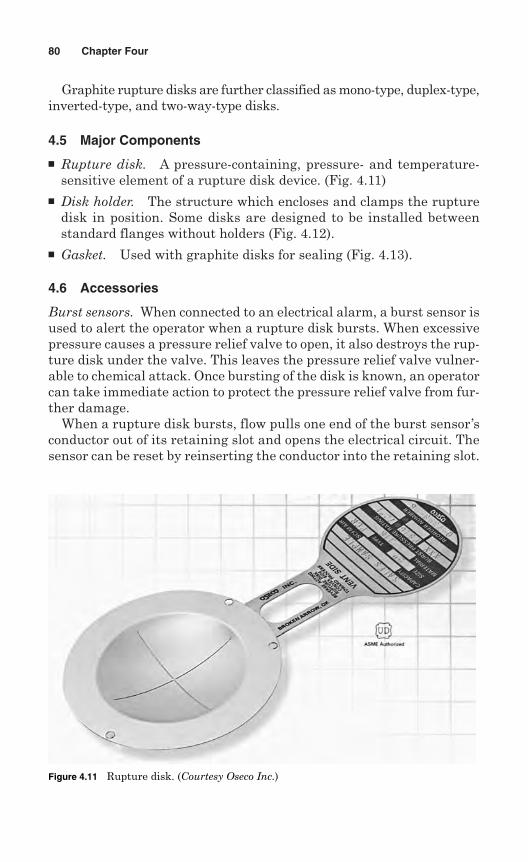
Graphite rupture disks are further classified as mono-type, duplex-type,inverted-type, and two-way-type disks.
4.5 Major Components
Rupture disk. A pressure-containing, pressure- and temperature-sensitive element of a rupture disk device. (Fig. 4.11)
Disk holder. The structure which encloses and clamps the rupturedisk in position. Some disks are designed to be installed betweenstandard flanges without holders (Fig. 4.12).
Gasket. Used with graphite disks for sealing (Fig. 4.13).
4.6 Accessories
Burst sensors. When connected to an electrical alarm, a burst sensor isused to alert the operator when a rupture disk bursts. When excessivepressure causes a pressure relief valve to open, it also destroys the rup-ture disk under the valve. This leaves the pressure relief valve vulner-able to chemical attack. Once bursting of the disk is known, an operatorcan take immediate action to protect the pressure relief valve from fur-ther damage.
When a rupture disk bursts, flow pulls one end of the burst sensor’sconductor out of its retaining slot and opens the electrical circuit. Thesensor can be reset by reinserting the conductor into the retaining slot.
80 Chapter Four
Figure 4.11 Rupture disk. (Courtesy Oseco Inc.)
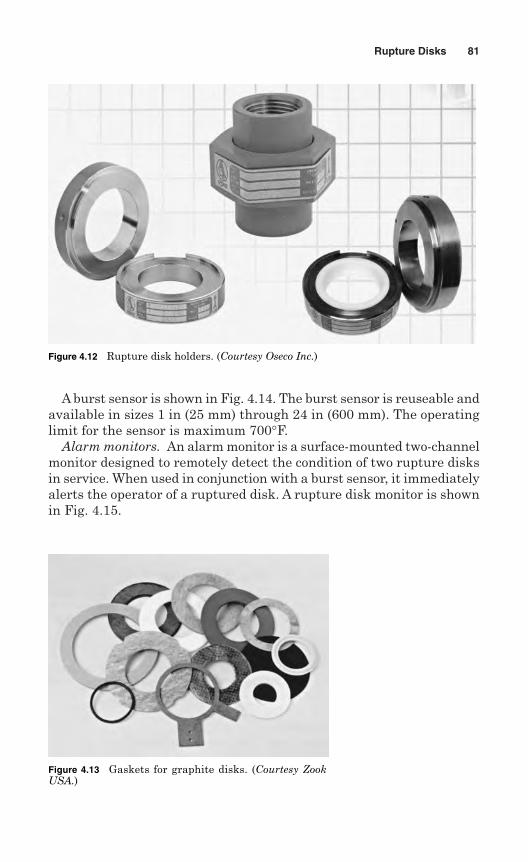
A burst sensor is shown in Fig. 4.14. The burst sensor is reuseable andavailable in sizes 1 in (25 mm) through 24 in (600 mm). The operatinglimit for the sensor is maximum 700°F.
Alarm monitors. An alarm monitor is a surface-mounted two-channelmonitor designed to remotely detect the condition of two rupture disksin service. When used in conjunction with a burst sensor, it immediatelyalerts the operator of a ruptured disk. A rupture disk monitor is shownin Fig. 4.15.
Rupture Disks 81
Figure 4.12 Rupture disk holders. (Courtesy Oseco Inc.)
Figure 4.13 Gaskets for graphite disks. (Courtesy ZookUSA.)
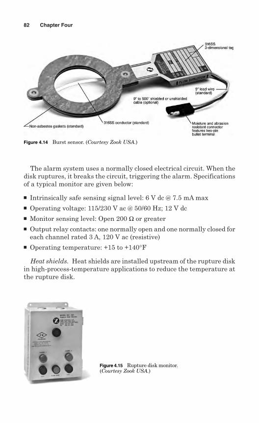
The alarm system uses a normally closed electrical circuit. When thedisk ruptures, it breaks the circuit, triggering the alarm. Specificationsof a typical monitor are given below:
Intrinsically safe sensing signal level: 6 V dc @ 7.5 mA max Operating voltage: 115/230 V ac @ 50/60 Hz; 12 V dc Monitor sensing level: Open 200 Ω or greater Output relay contacts: one normally open and one normally closed for
each channel rated 3 A, 120 V ac (resistive) Operating temperature: +15 to +140°F
Heat shields. Heat shields are installed upstream of the rupture diskin high-process-temperature applications to reduce the temperature atthe rupture disk.
82 Chapter Four
Figure 4.14 Burst sensor. (Courtesy Zook USA.)
Figure 4.15 Rupture disk monitor.(Courtesy Zook USA.)
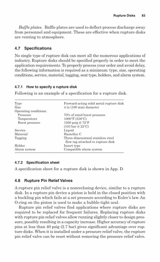
Baffle plates. Baffle plates are used to deflect process discharge awayfrom personnel and equipment. These are effective when rupture disksare venting to atmosphere.
4.7 Specifications
No single type of rupture disk can meet all the numerous applications ofindustry. Rupture disks should be specified properly in order to meet theapplication requirements. To properly process your order and avoid delay,the following information is required as a minimum: type, size, operatingconditions, service, material, tagging, seat type, holders, and alarm system.
4.7.1 How to specify a rupture disk
Following is an example of a specification for a rupture disk.
Type Forward-acting solid metal rupture diskSize 4 in (100 mm) diameterOperating conditions:
Pressure 70% of rated burst pressureTemperature 1000°F (538°C)Burst pressure 1500 psig @ 72°F
(103 bar @ 22°C)Service LiquidMaterial Hastelloy CTagging Three-dimensional stainless steel
flow tag attached to rupture diskHolder Insert typeAlarm system Compatible alarm system
4.7.2 Specification sheet
A specification sheet for a rupture disk is shown in App. D.
4.8 Rupture Pin Relief Valves
A rupture pin relief valve is a nonreclosing device, similar to a rupturedisk. In a rupture pin device a piston is held in the closed position witha buckling pin which fails at a set pressure according to Euler’s law. AnO-ring on the piston is used to make a bubble-tight seal.
Rupture pin relief valves find applications where rupture disks arerequired to be replaced for frequent failures. Replacing rupture diskswith rupture pin relief valves allow running slightly closer to design pres-sure, possibly resulting in a capacity increase. Higher accuracy of rupturepins at less than 40 psig (2.7 bar) gives significant advantage over rup-ture disks. When it is installed under a pressure relief valve, the rupturepin relief valve can be reset without removing the pressure relief valve.
Rupture Disks 83
4.8.1 Comparison of rupture pins and rupture disks
Rupture pin relief valves have distinct advantages over rupture disks.The following are advantages:
Not subject to premature failure due to fatigue. Suitable for any type of liquid service. Available as balanced or unbalanced device. Suitable for operating closer to its set point. Set point is insensitive to operating temperature. Suitable for operating as low as 0.1 psig (0.007 bar). Resetting after release usually requires no breaking of flanges. Replacement pins are one-third to one-quarter the cost of replace-
ment disks.
The following are considered disadvantages of using rupture pin reliefvalves instead of rupture disks:
The elastomer O-ring seal limits the maximum operating temperatureto about 450°F (230°C).
Initial cost of installation is greater than for a rupture disk:- Twice as costly for 2-in carbon steel- Up to seven times as costly for 8-in stainless steel
4.9 Buckling Pin Relief Valves
A buckling pin relief valve is an inline relief device which provides quickand simple reset without removing the valve from the piping system.This nonreclosing pressure relief device offers practical technology forthe protection of many applications in refinery, petrochemical, and otherprocessing industries. A buckling pin relief valve is shown in Fig. 4.16.
The buckling pin relief valve has three primary components: a rotat-ing disk, a flanged body, and an external enclosure and mechanism.
Rotating disk. A rotating disk normally closes the flow path andturns 90° in response to an overpressure/underpressure condition.The rotating disk is constructed from metal and has a hollow design.
Flanged body. A flanged body contains the rotating disk, holdingit in place using shaft connections which are sealed within the bodyand pass through bearings to permit free rotation of the disk withinthe body.
84 Chapter Four
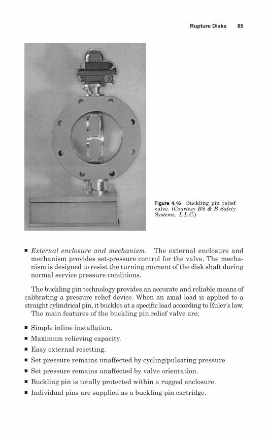
External enclosure and mechanism. The external enclosure andmechanism provides set-pressure control for the valve. The mecha-nism is designed to resist the turning moment of the disk shaft duringnormal service pressure conditions.
The buckling pin technology provides an accurate and reliable means ofcalibrating a pressure relief device. When an axial load is applied to astraight cylindrical pin, it buckles at a specific load according to Euler’s law.
The main features of the buckling pin relief valve are:
Simple inline installation. Maximum relieving capacity. Easy external resetting. Set pressure remains unaffected by cycling/pulsating pressure. Set pressure remains unaffected by valve orientation. Buckling pin is totally protected within a rugged enclosure. Individual pins are supplied as a buckling pin cartridge.
Rupture Disks 85
Figure 4.16 Buckling pin reliefvalve. (Courtesy BS & B SafetySystems, L.L.C.)
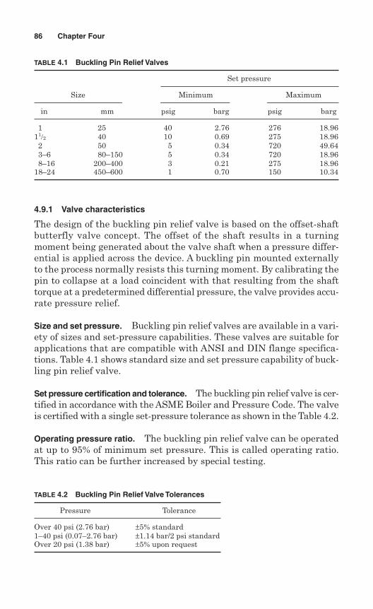
4.9.1 Valve characteristics
The design of the buckling pin relief valve is based on the offset-shaftbutterfly valve concept. The offset of the shaft results in a turningmoment being generated about the valve shaft when a pressure differ-ential is applied across the device. A buckling pin mounted externallyto the process normally resists this turning moment. By calibrating thepin to collapse at a load coincident with that resulting from the shafttorque at a predetermined differential pressure, the valve provides accu-rate pressure relief.
Size and set pressure. Buckling pin relief valves are available in a vari-ety of sizes and set-pressure capabilities. These valves are suitable forapplications that are compatible with ANSI and DIN flange specifica-tions. Table 4.1 shows standard size and set pressure capability of buck-ling pin relief valve.
Set pressure certification and tolerance. The buckling pin relief valve is cer-tified in accordance with the ASME Boiler and Pressure Code. The valveis certified with a single set-pressure tolerance as shown in the Table 4.2.
Operating pressure ratio. The buckling pin relief valve can be operatedat up to 95% of minimum set pressure. This is called operating ratio.This ratio can be further increased by special testing.
86 Chapter Four
TABLE 4.1 Buckling Pin Relief Valves
Set pressure
Size Minimum Maximum
in mm psig barg psig barg
1 25 40 2.76 276 18.9611/2 40 10 0.69 275 18.962 50 5 0.34 720 49.643–6 80–150 5 0.34 720 18.968–16 200–400 3 0.21 275 18.96
18–24 450–600 1 0.70 150 10.34
TABLE 4.2 Buckling Pin Relief Valve Tolerances
Pressure Tolerance
Over 40 psi (2.76 bar) ±5% standard1–40 psi (0.07–2.76 bar) ±1.14 bar/2 psi standardOver 20 psi (1.38 bar) ±5% upon request
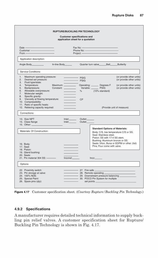
4.9.2 Specifications
A manufacturer requires detailed technical information to supply buck-ling pin relief valves. A customer specification sheet for Rupture/Buckling Pin Technology is shown in Fig. 4.17.
Rupture Disks 87
RUPTURE/BUCKLING PIN TECHNOLOGY
Customer specifications andapplication sheet for a quotation
Date ————————————Customer ——————————From ————————————
Fax No: ———————————————Phone No: ——————————————Project: ———————————————
1. Maximum operating pressure:2. Desired set pressure:3. Fluid type/state:4. Temperature:5. Backpressure:6. Allowable overpressure:7. Molecular weight:8. Specific gravity:9. Viscosity at flowing temperature:10. Compressibility:11. Ratio of specific heats:12. Relieving capacity required:
13. Size NPT14. Class flange15. Other: —————————————
Inlet:———Inlet:———
Angle Body————— In-line Body——— Quarter turn valve———Ball———Butterlly
——————————————————————————————Inconel:———
Outlet:———Outlet:———
16. Body:17. Seat:18. Piston:19. Gland bushing:20. Seals:21. Pin material 304 SS: ————
22. Proximity switch:23. Pin storage at valve:24. 100% NDE:25. Special Paint:26. Spare pins (qty):
27. Fire safe —————————————————28. Remote operating —————————————29. Downstream pressure balancing ———————30. POCO Pin System for multiple
set points —————————————————
——————————————————————————————
(or provide other units)(or provide other units)
(or provide other units)(or provide other units)
PSIGPSIG
Operating:Variable:
Degrees FPSIG
——————
Maximum:Constant:
———————————————————————————————————————————————————————————————
%
CP
(10% standard)
(Provide unit of measure)
Inco:———
Application description:
Service Conditions:
Connections:
Materials: Of Construction:
Options:
Standard Options of Materials:
Body: C/S, low temperature C/S or SS.Seat: Stainless steel.Piston: SS with 17-4 SS stem.Bushing: Aluminum bronze or SS.Seals: Viton, Buna or EDPM or other. (list)Pins: Four come with valve.
Figure 4.17 Customer specification sheet. (Courtesy Rupture/Buckling Pin Technology.)

This page intentionally left blank
Chapter
5Materials
Materials for construction of pressure relief valves and their major partsare listed in American Society of Mechanical Code Section II—Materials.This Code has four parts:
Part A—Ferrous Material Specifications
Part B—Nonferrous Material Specifications
Part C—Specifications for Welding Rods, Electrodes, and Filler Metals
Part D—Properties
Materials for minor components are either listed in ASME Section IIor in ASTM specifications, or are controlled by the manufacturer accord-ing to a specification equivalent to an ASTM standard. In the lattercase, the manufacturer is responsible for ensuring that the allowablestresses at design temperature meet the requirements of ASME Section II,Part D, Appendix I—Nonmandatory Basis for Establishing Stress valuesin Tables 1A and 1B.
5.1 Pressure Relief Valves
During operation, the pressure parts that are wetted by the processfluid are the inlet nozzle and the disk. For most applications, all othercomponents are made from standard materials. Special materials arerequired for the following applications:
Cryogenic applications Corrosive fluids Where contamination of discharged fluid is not allowed
89
Copyright © 2006 by The McGraw-Hill Companies, Inc. Click here for terms of use.
When the valve discharges into a manifold which contains corrosivefluid discharged by another valve
It is important that moving parts such as spindle and guides are con-structed from the materials that are not easily degraded or corroded. Asseats and disks are constantly in contact with the fluid, they should beable to resist the effects of erosion and corrosion. Austenitic stainlesssteel is commonly used for seats and disks; sometimes they are “satel-lite faced” for increased durability. Nozzles, disks, and seats that willbe exposed to corrosive fluids are constructed from special alloys suchas Monel or Hastelloy.
The spring is a very critical component of any pressure relief valve andshould provide reliable service. Standard pressure relief valves typicallyuse carbon steel for applications at moderate temperatures. Tungstensteel is used for higher-temperature but noncorrosive applications.Stainless steel is used for corrosive or clean steam applications. Specialmaterials such as Monel, Hastelloy, and Inconel are used for sour-gasand high-temperature applications.
The major pressure-retaining components of pressure relief valves aregenerally constructed from the following materials: bronze, cast iron,cast steel, austenitic steel, Monel, Inconel, and Hastelloy.
5.1.1 Materials
Materials of construction are specified in the construction codes forpressure relief valves. Generally the following materials are used for con-struction: copper alloys, cast iron, cast steels, austenitic stainless steels,and nickel alloys.
Copper alloys. There are several copper alloy systems, which includebrasses, bronzes, and cupronickls. These are single-phase alloys ofcopper used for corrosion resistance.
Brasses are wrought alloys of copper and zinc. The zinc content variesfrom 5% to 50% Zn. Some wrought brasses may contain additions of tinand other elements. Brasses consist of three groups: alpha and betabrass, tin brass, and leaded brass.
Commercial bronze, C22000, is an alpha brass with 10% Zn.Manganese bronzes are high-strength beta brass containing 55–60%Cu and 38–42% Zn. Tin bronzes are wrought and cast alloys of copperand tin. Silicon bronzes are wrought and cast alloys of copper with 1–5%Si and additions of manganese, iron, and zinc.
Cupronickels (copper-nickels) are wrought and cast alloys of copper con-taining up to 30% Ni, plus minor additions of chromium, tin. beryllium,
90 Chapter Five
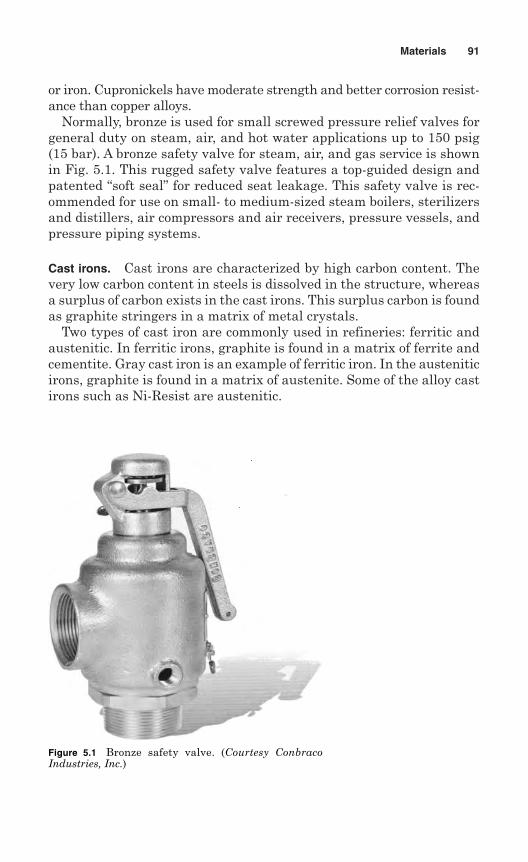
or iron. Cupronickels have moderate strength and better corrosion resist-ance than copper alloys.
Normally, bronze is used for small screwed pressure relief valves forgeneral duty on steam, air, and hot water applications up to 150 psig(15 bar). A bronze safety valve for steam, air, and gas service is shownin Fig. 5.1. This rugged safety valve features a top-guided design andpatented “soft seal” for reduced seat leakage. This safety valve is rec-ommended for use on small- to medium-sized steam boilers, sterilizersand distillers, air compressors and air receivers, pressure vessels, andpressure piping systems.
Cast irons. Cast irons are characterized by high carbon content. Thevery low carbon content in steels is dissolved in the structure, whereasa surplus of carbon exists in the cast irons. This surplus carbon is foundas graphite stringers in a matrix of metal crystals.
Two types of cast iron are commonly used in refineries: ferritic andaustenitic. In ferritic irons, graphite is found in a matrix of ferrite andcementite. Gray cast iron is an example of ferritic iron. In the austeniticirons, graphite is found in a matrix of austenite. Some of the alloy castirons such as Ni-Resist are austenitic.
Materials 91
Figure 5.1 Bronze safety valve. (Courtesy ConbracoIndustries, Inc.)
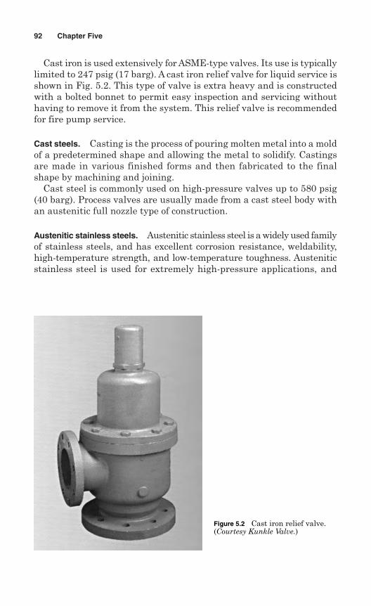
Cast iron is used extensively for ASME-type valves. Its use is typicallylimited to 247 psig (17 barg). A cast iron relief valve for liquid service isshown in Fig. 5.2. This type of valve is extra heavy and is constructedwith a bolted bonnet to permit easy inspection and servicing withouthaving to remove it from the system. This relief valve is recommendedfor fire pump service.
Cast steels. Casting is the process of pouring molten metal into a moldof a predetermined shape and allowing the metal to solidify. Castingsare made in various finished forms and then fabricated to the finalshape by machining and joining.
Cast steel is commonly used on high-pressure valves up to 580 psig(40 barg). Process valves are usually made from a cast steel body withan austenitic full nozzle type of construction.
Austenitic stainless steels. Austenitic stainless steel is a widely used familyof stainless steels, and has excellent corrosion resistance, weldability,high-temperature strength, and low-temperature toughness. Austeniticstainless steel is used for extremely high-pressure applications, and
92 Chapter Five
Figure 5.2 Cast iron relief valve.(Courtesy Kunkle Valve.)
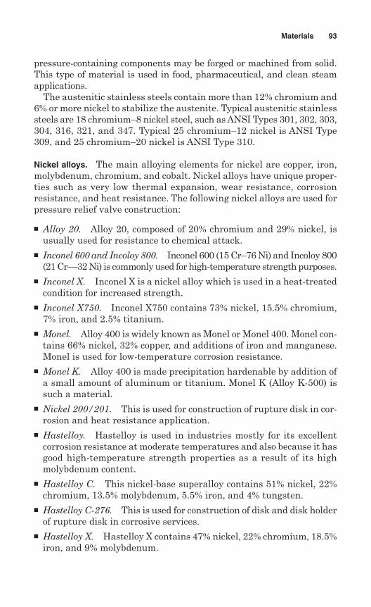
pressure-containing components may be forged or machined from solid.This type of material is used in food, pharmaceutical, and clean steamapplications.
The austenitic stainless steels contain more than 12% chromium and6% or more nickel to stabilize the austenite. Typical austenitic stainlesssteels are 18 chromium–8 nickel steel, such as ANSI Types 301, 302, 303,304, 316, 321, and 347. Typical 25 chromium–12 nickel is ANSI Type309, and 25 chromium–20 nickel is ANSI Type 310.
Nickel alloys. The main alloying elements for nickel are copper, iron,molybdenum, chromium, and cobalt. Nickel alloys have unique proper-ties such as very low thermal expansion, wear resistance, corrosionresistance, and heat resistance. The following nickel alloys are used forpressure relief valve construction:
Alloy 20. Alloy 20, composed of 20% chromium and 29% nickel, isusually used for resistance to chemical attack.
Inconel 600 and Incoloy 800. Inconel 600 (15 Cr–76 Ni) and Incoloy 800(21 Cr––32 Ni) is commonly used for high-temperature strength purposes.
Inconel X. Inconel X is a nickel alloy which is used in a heat-treatedcondition for increased strength.
Inconel X750. Inconel X750 contains 73% nickel, 15.5% chromium,7% iron, and 2.5% titanium.
Monel. Alloy 400 is widely known as Monel or Monel 400. Monel con-tains 66% nickel, 32% copper, and additions of iron and manganese.Monel is used for low-temperature corrosion resistance.
Monel K. Alloy 400 is made precipitation hardenable by addition ofa small amount of aluminum or titanium. Monel K (Alloy K-500) issuch a material.
Nickel 200/201. This is used for construction of rupture disk in cor-rosion and heat resistance application.
Hastelloy. Hastelloy is used in industries mostly for its excellentcorrosion resistance at moderate temperatures and also because it hasgood high-temperature strength properties as a result of its highmolybdenum content.
Hastelloy C. This nickel-base superalloy contains 51% nickel, 22%chromium, 13.5% molybdenum, 5.5% iron, and 4% tungsten.
Hastelloy C-276. This is used for construction of disk and disk holderof rupture disk in corrosive services.
Hastelloy X. Hastelloy X contains 47% nickel, 22% chromium, 18.5%iron, and 9% molybdenum.
Materials 93
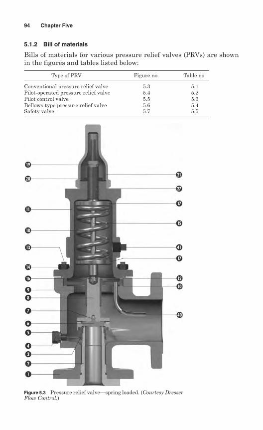
5.1.2 Bill of materials
Bills of materials for various pressure relief valves (PRVs) are shownin the figures and tables listed below:
Type of PRV Figure no. Table no.
Conventional pressure relief valve 5.3 5.1Pilot-operated pressure relief valve 5.4 5.2Pilot control valve 5.5 5.3Bellows-type pressure relief valve 5.6 5.4Safety valve 5.7 5.5
94 Chapter Five
Figure 5.3 Pressure relief valve—spring loaded. (Courtesy DresserFlow Control.)
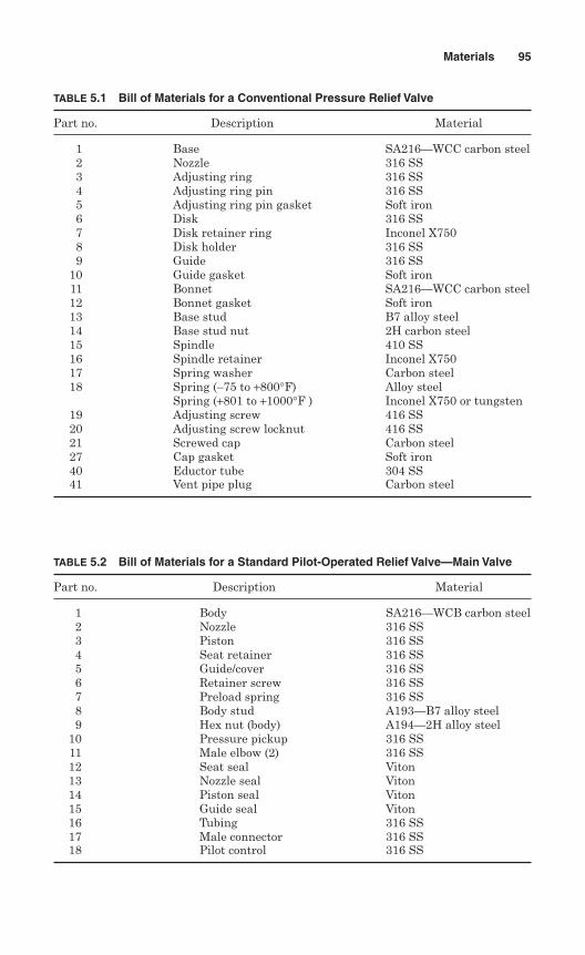
Materials 95
TABLE 5.1 Bill of Materials for a Conventional Pressure Relief Valve
Part no. Description Material
1 Base SA216—WCC carbon steel2 Nozzle 316 SS3 Adjusting ring 316 SS4 Adjusting ring pin 316 SS5 Adjusting ring pin gasket Soft iron6 Disk 316 SS7 Disk retainer ring Inconel X7508 Disk holder 316 SS9 Guide 316 SS
10 Guide gasket Soft iron11 Bonnet SA216—WCC carbon steel12 Bonnet gasket Soft iron13 Base stud B7 alloy steel14 Base stud nut 2H carbon steel15 Spindle 410 SS16 Spindle retainer Inconel X75017 Spring washer Carbon steel18 Spring (–75 to +800°F) Alloy steel
Spring (+801 to +1000°F ) Inconel X750 or tungsten19 Adjusting screw 416 SS20 Adjusting screw locknut 416 SS21 Screwed cap Carbon steel27 Cap gasket Soft iron40 Eductor tube 304 SS41 Vent pipe plug Carbon steel
TABLE 5.2 Bill of Materials for a Standard Pilot-Operated Relief Valve—Main Valve
Part no. Description Material
1 Body SA216—WCB carbon steel2 Nozzle 316 SS3 Piston 316 SS4 Seat retainer 316 SS5 Guide/cover 316 SS6 Retainer screw 316 SS7 Preload spring 316 SS8 Body stud A193—B7 alloy steel9 Hex nut (body) A194—2H alloy steel
10 Pressure pickup 316 SS11 Male elbow (2) 316 SS12 Seat seal Viton13 Nozzle seal Viton14 Piston seal Viton15 Guide seal Viton16 Tubing 316 SS17 Male connector 316 SS18 Pilot control 316 SS
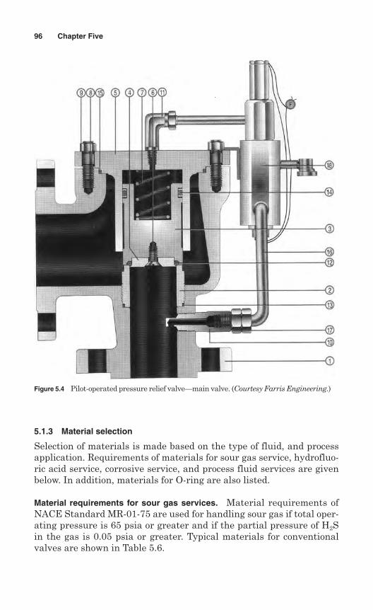
5.1.3 Material selection
Selection of materials is made based on the type of fluid, and processapplication. Requirements of materials for sour gas service, hydrofluo-ric acid service, corrosive service, and process fluid services are givenbelow. In addition, materials for O-ring are also listed.
Material requirements for sour gas services. Material requirements ofNACE Standard MR-01-75 are used for handling sour gas if total oper-ating pressure is 65 psia or greater and if the partial pressure of H2Sin the gas is 0.05 psia or greater. Typical materials for conventionalvalves are shown in Table 5.6.
96 Chapter Five
Figure 5.4 Pilot-operated pressure relief valve—main valve. (Courtesy Farris Engineering.)
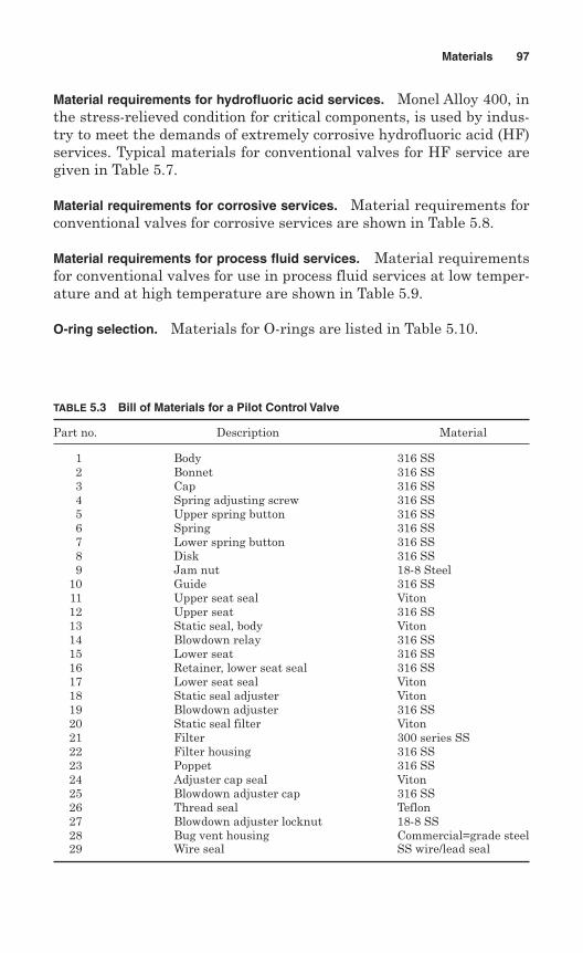
Material requirements for hydrofluoric acid services. Monel Alloy 400, inthe stress-relieved condition for critical components, is used by indus-try to meet the demands of extremely corrosive hydrofluoric acid (HF)services. Typical materials for conventional valves for HF service aregiven in Table 5.7.
Material requirements for corrosive services. Material requirements forconventional valves for corrosive services are shown in Table 5.8.
Material requirements for process fluid services. Material requirementsfor conventional valves for use in process fluid services at low temper-ature and at high temperature are shown in Table 5.9.
O-ring selection. Materials for O-rings are listed in Table 5.10.
Materials 97
TABLE 5.3 Bill of Materials for a Pilot Control Valve
Part no. Description Material
1 Body 316 SS2 Bonnet 316 SS3 Cap 316 SS4 Spring adjusting screw 316 SS5 Upper spring button 316 SS6 Spring 316 SS7 Lower spring button 316 SS8 Disk 316 SS9 Jam nut 18-8 Steel
10 Guide 316 SS11 Upper seat seal Viton12 Upper seat 316 SS13 Static seal, body Viton14 Blowdown relay 316 SS15 Lower seat 316 SS16 Retainer, lower seat seal 316 SS17 Lower seat seal Viton18 Static seal adjuster Viton19 Blowdown adjuster 316 SS20 Static seal filter Viton21 Filter 300 series SS22 Filter housing 316 SS23 Poppet 316 SS24 Adjuster cap seal Viton25 Blowdown adjuster cap 316 SS26 Thread seal Teflon27 Blowdown adjuster locknut 18-8 SS28 Bug vent housing Commercial=grade steel29 Wire seal SS wire/lead seal
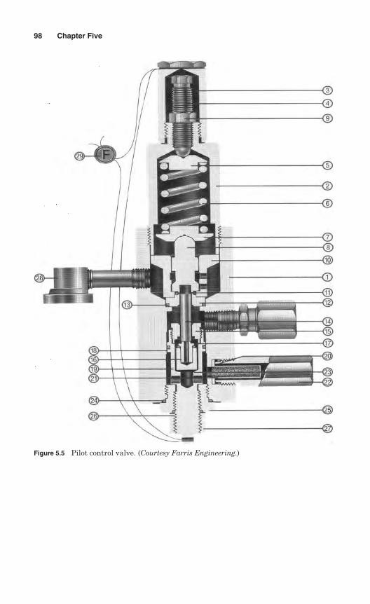
98 Chapter Five
Figure 5.5 Pilot control valve. (Courtesy Farris Engineering.)
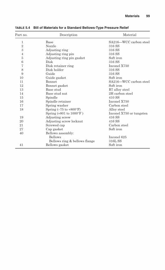
Materials 99
TABLE 5.4 Bill of Materials for a Standard Bellows-Type Pressure Relief
Part no. Description Material
1 Base SA216—WCC carbon steel2 Nozzle 316 SS3 Adjusting ring 316 SS4 Adjusting ring pin 316 SS5 Adjusting ring pin gasket Soft iron6 Disk 316 SS7 Disk retainer ring Inconel X7508 Disk holder 316 SS9 Guide 316 SS
10 Guide gasket Soft iron11 Bonnet SA216—WCC carbon steel12 Bonnet gasket Soft iron13 Base stud B7 alloy steel14 Base stud nut 2H carbon steel15 Spindle 410 SS16 Spindle retainer Inconel X75017 Spring washer Carbon steel18 Spring (–75 to +800°F) Alloy steel
Spring (+801 to 1000°F ) Inconel X750 or tungsten19 Adjusting screw 416 SS20 Adjusting screw locknut 416 SS21 Screwed cap Carbon steel27 Cap gasket Soft iron40 Bellows assembly:
Bellows Inconel 625Bellows ring & bellows flange 316L SS
41 Bellows gasket Soft iron
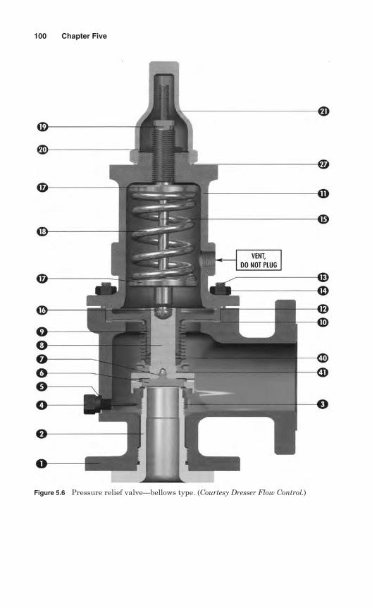
100 Chapter Five
Figure 5.6 Pressure relief valve—bellows type. (Courtesy Dresser Flow Control.)
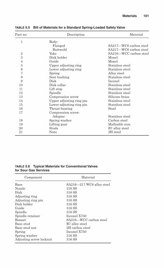
Materials 101
TABLE 5.5 Bill of Materials for a Standard Spring-Loaded Safety Valve
Part no. Description Material
1 Body:Flanged SA217—WC6 carbon steelButtweld SA217—WC6 carbon steel
2 Yoke SA216—WCC carbon steel3 Disk holder Monel4 Guide Monel5 Upper adjusting ring Stainless steel6 Lower adjusting ring Stainless steel7 Spring Alloy steel8 Seat bushing Stainless steel9 Disk Inconel
10 Disk collar Stainless steel11 Lift stop Stainless steel12 Spindle Stainless steel13 Compression screw Silicone brass14 Upper adjusting ring pin Stainless steel15 Lower adjusting ring pin Stainless steel16 Thrust bearing Steel17 Compression screw:
Adopter Stainless steel18 Spring washer Carbon steel19 Lifting gear Malleable iron20 Studs B7 alloy steel21 Nuts 2H steel
TABLE 5.6 Typical Materials for Conventional Valves for Sour Gas Services
Component Material
Base SA216—217 WC6 alloy steelNozzle 316 SSDisk 316 SSAdjusting ring 316 SSAdjusting ring pin 316 SSDisk holder 316 SSGuide 316 SSSpindle 316 SSSpindle retainer Inconel X750Bonnet SA216—WCC carbon steelBase stud B7 alloy steelBase stud nut 2H carbon steelSpring Inconel X750Spring washer 316 SSAdjusting screw locknut 316 SS
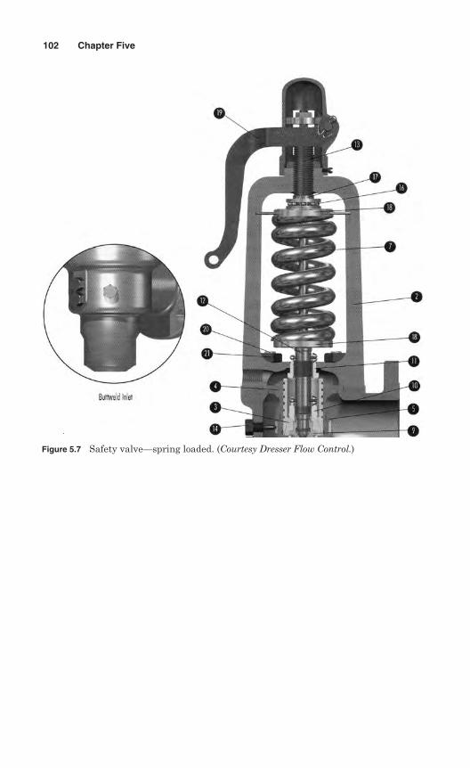
102 Chapter Five
Figure 5.7 Safety valve—spring loaded. (Courtesy Dresser Flow Control.)
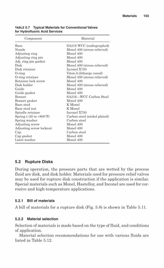
Materials 103
TABLE 5.7 Typical Materials for Conventional Valvesfor Hydrofluoric Acid Services
Component Material
Base SA216 WCC (radiographed)Nozzle Monel 400 (stress relieved)Adjusting ring Monel 400Adjusting ring pin Monel 400Adj. ring pin gasket Monel 400Disk Monel 400 (stress relieved)Disk retainer Inconel X750O-ring Viton A (litharge cured)O-ring retainer Monel 400 (stress relieved)Retainer lock screw Monel 400Disk holder Monel 400 (stress relieved)Guide Monel 400Guide gasket Monel 400Bonnet SA216—WCC Carbon SteelBonnet gasket Monel 400Base stud K MonelBase stud nut K MonelSpindle retainer Inconel X750Spring (–20 to +800°F) Carbon steel (nickel plated)Spring washer Carbon steelAdjusting screw Monel 400Adjusting screw locknut Monel 400Cap Carbon steelCap gasket Monel 400Limit washer Monel 400
5.2 Rupture Disks
During operation, the pressure parts that are wetted by the processfluid are disk, and disk holder. Materials used for pressure relief valvesmay be used for rupture disk construction if the application is similar.Special materials such as Monel, Hastelloy, and Inconel are used for cor-rosive and high-temperature applications.
5.2.1 Bill of materials
A bill of materials for a rupture disk (Fig. 5.8) is shown in Table 5.11.
5.2.2 Material selection
Selection of materials is made based on the type of fluid, and conditionsof application.
Material selection recommendations for use with various fluids arelisted in Table 5.12.
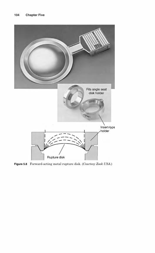
104 Chapter Five
Figure 5.8 Forward-acting metal rupture disk. (Courtesy Zook USA.)
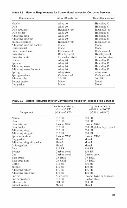
TABLE 5.8 Material Requirements for Conventional Valves for Corrosive Services
Components Alloy 20 material Hastelloy material
Nozzle Alloy 20 Hastelloy CDisk Alloy 20 Hastelloy CDisk retainer Inconel X750 Inconel X750Disk holder Alloy 20 Hastelloy CAdjusting ring Alloy 20 Hastelloy CAdjusting ring pin Alloy 20 Hastelloy CSpindle retainer Inconel X750 Inconel X750Adjusting ring pin gasket Monel MonelGuide basket Monel MonelBase, bonnet, cap Carbon steel Carbon steelBase studs B7 alloy steel B7 alloy steelBase stud nuts 2H carbon steel 2H carbon steelGuide Alloy 20 Hastelloy CSpindle Alloy 20 Hastelloy CAdjusting screw Alloy 20 Hastelloy CAdjusting screw locknut Alloy 20 Hastelloy CSpring Alloy steel Alloy steelSpring washers Carbon steel Carbon steelEductor tube 304 SS 304 SSBonnet gasket Monel MonelCap gasket Monel Monel
TABLE 5.9 Material Requirements for Conventional Valves for Process Fluid Services
Low temperature, High temperature,–21 to –75°F +1001 to +1200°F
Component (–29 to –59°C) (+538 to +649°C)
Nozzle 316 SS 316 SSDisk 316 SS 316 SSDisk retainer Inconel X750 Inconel X750Disk holder 316 SS 316 SS glide-alloy treatedAdjusting ring 316 SS 316 SSAdjusting ring pin 316 SS 316 SSSpindle retainer Inconel X750 Inconel X750Cap gasket Monel MonelAdjusting ring pin gasket Monel MonelGuide gasket Monel MonelBase 316 SS 316 SSBonnet Carbon steel 316 SSCap Carbon steel Carbon steelBase studs Gr. B8M Gr. B8MBase stud nuts Gr. G8M Gr. B8MGuide 316 SS 316 SSSpindle 410 SS 410 SSAdjusting screw 416 SS 416 SSAdjusting screw nut 416 SS 416 SSSpring Alloy steel Inconel X750 or tungstenSpring washers 316 SS Carbon steelEductor tube 304 SS 304 SSBonnet gasket Monel Monel
105
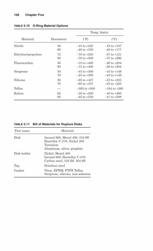
106 Chapter Five
TABLE 5.10 O-Ring Material Options
Temp. limits
Material Durometer (°F) (°C)
Nitrile 50 –45 to +225 –43 to +10790 –40 to +350 –40 to +177
Ethylene/propylene 75 –70 to +250 –57 to +12190 –70 to +500 –57 to +260
Fluorocarbon 50 –15 to +400 –26 to +20490 –15 to +400 –26 to +204
Neoprene 50 –45 to +300 –43 to +14970 –45 to +300 –43 to +149
Silicone 50 –65 to +437 –53 to +22570 –65 to +437 –53 to +225
Teflon — –300 to +500 –184 to +260
Kalrez 65 –40 to +500 –40 to +26082 –42 to +550 –41 to +288
TABLE 5.11 Bill of Materials for Rupture Disks
Part name Material
Disk Inconel 600, Monel 400, 316 SSHastelloy C-276, Nickel 200TantalumAluminum, silver, graphite
Disk holder Nickel, Monel 400Inconel 600, Hastelloy C-276Carbon steel, 316 SS, 304 SS
Tag Stainless steel
Gasket Viton, EPDM, PTFE TeflonNeoprene, silicone, non-asbestos
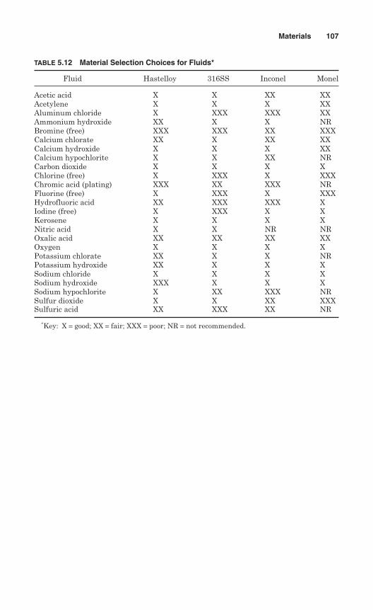
Materials 107
TABLE 5.12 Material Selection Choices for Fluids*
Fluid Hastelloy 316SS Inconel Monel
Acetic acid X X XX XXAcetylene X X X XXAluminum chloride X XXX XXX XXAmmonium hydroxide XX X X NRBromine (free) XXX XXX XX XXXCalcium chlorate XX X XX XXCalcium hydroxide X X X XXCalcium hypochlorite X X XX NRCarbon dioxide X X X XChlorine (free) X XXX X XXXChromic acid (plating) XXX XX XXX NRFluorine (free) X XXX X XXXHydrofluoric acid XX XXX XXX XIodine (free) X XXX X XKerosene X X X XNitric acid X X NR NROxalic acid XX XX XX XXOxygen X X X XPotassium chlorate XX X X NRPotassium hydroxide XX X X XSodium chloride X X X XSodium hydroxide XXX X X XSodium hypochlorite X XX XXX NRSulfur dioxide X X XX XXXSulfuric acid XX XXX XX NR
∗Key: X = good; XX = fair; XXX = poor; NR = not recommended.

This page intentionally left blank
Chapter
6Design
The spring-loaded pressure relief valve (PRV) is referred to as a “standard”or “conventional” pressure relief valve. This standard pressure reliefvalve is a simple and self-acting device, which provides overpressureprotection.
The basic elements of design of a standard pressure relief valve con-sist of a right-angle-pattern valve body with the valve inlet connectionor nozzle mounted on the pressure-containing side of the vessel. Theoutlet connection may be screwed or flanged for connection to a pipe thatis discharged to a suitable safe location. A pressure relief safety valvedesign is shown in Fig. 6.1.
In a spring-loaded valve, the pressure force required to lift the seatdisk is the preload of the spring, which is equal to the pressure underthe disk times the seat sealing area, plus the force required to com-press the spring as the valve opens. This compression force is equal tothe spring rate times the lift of the seat disk, and must be generatedduring the allowable pressure.
A design feature applied to further compress the spring and achievelift is the addition of a “skirt” to the seat disk, as shown in Fig. 6.2. Theskirt redirects the flow downward as it discharges through the nozzle,resulting in a change in momentum. The fluid also expands and acts overa larger area. Both the momentum change and expansion significantlyincrease the force available to compress the spring.
In order to achieve a significant lift, a ring is added around the valvenozzle and positioned to form a huddling chamber with the disk skirt(Fig. 6.2). The ring is generally called a blowdown ring, and its functionis important for controlling the valve opening.
If the blowdown ring is adjusted up, the forces required to lift the seatdisk off the nozzle occur at pressure very close to the set pressure. With the
109
Copyright © 2006 by The McGraw-Hill Companies, Inc. Click here for terms of use.
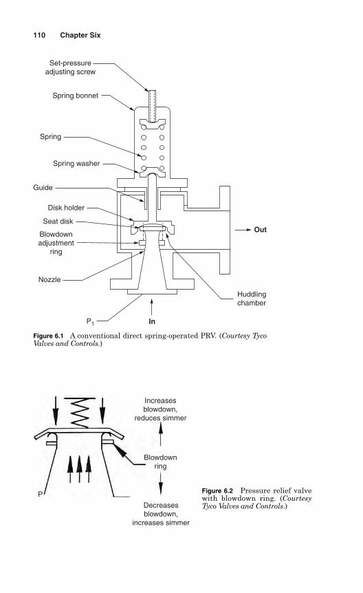
110 Chapter Six
P
Decreasesblowdown,
increases simmer
Blowdownring
Increasesblowdown,
reduces simmer
Figure 6.2 Pressure relief valvewith blowdown ring. (CourtesyTyco Valves and Controls.)
Nozzle
Seat disk
In
Huddlingchamber
Out
P1
Blowdownadjustment
ring
Disk holder
Guide
Spring washer
Spring
Spring bonnet
Set-pressureadjusting screw
Figure 6.1 A conventional direct spring-operated PRV. (Courtesy TycoValves and Controls.)
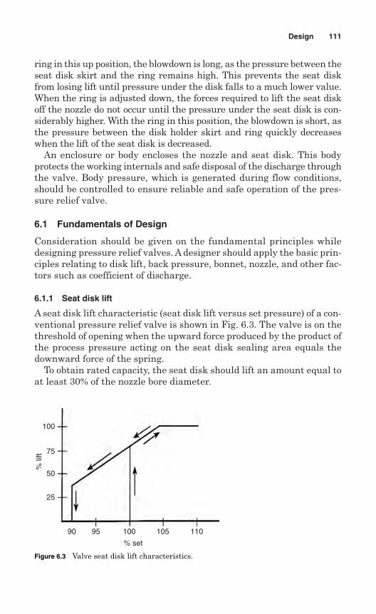
ring in this up position, the blowdown is long, as the pressure between theseat disk skirt and the ring remains high. This prevents the seat diskfrom losing lift until pressure under the disk falls to a much lower value.When the ring is adjusted down, the forces required to lift the seat diskoff the nozzle do not occur until the pressure under the seat disk is con-siderably higher. With the ring in this position, the blowdown is short, asthe pressure between the disk holder skirt and ring quickly decreaseswhen the lift of the seat disk is decreased.
An enclosure or body encloses the nozzle and seat disk. This bodyprotects the working internals and safe disposal of the discharge throughthe valve. Body pressure, which is generated during flow conditions,should be controlled to ensure reliable and safe operation of the pres-sure relief valve.
6.1 Fundamentals of Design
Consideration should be given on the fundamental principles whiledesigning pressure relief valves. A designer should apply the basic prin-ciples relating to disk lift, back pressure, bonnet, nozzle, and other fac-tors such as coefficient of discharge.
6.1.1 Seat disk lift
A seat disk lift characteristic (seat disk lift versus set pressure) of a con-ventional pressure relief valve is shown in Fig. 6.3. The valve is on thethreshold of opening when the upward force produced by the product ofthe process pressure acting on the seat disk sealing area equals thedownward force of the spring.
To obtain rated capacity, the seat disk should lift an amount equal toat least 30% of the nozzle bore diameter.
Design 111
100
75
50
25
9590 100 105 110
% set
% li
ft
Figure 6.3 Valve seat disk lift characteristics.
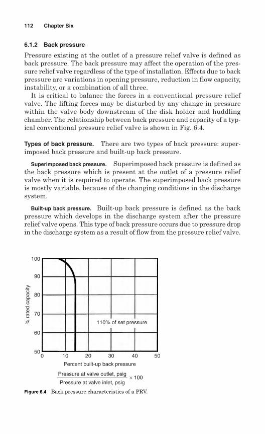
6.1.2 Back pressure
Pressure existing at the outlet of a pressure relief valve is defined asback pressure. The back pressure may affect the operation of the pres-sure relief valve regardless of the type of installation. Effects due to backpressure are variations in opening pressure, reduction in flow capacity,instability, or a combination of all three.
It is critical to balance the forces in a conventional pressure reliefvalve. The lifting forces may be disturbed by any change in pressurewithin the valve body downstream of the disk holder and huddlingchamber. The relationship between back pressure and capacity of a typ-ical conventional pressure relief valve is shown in Fig. 6.4.
Types of back pressure. There are two types of back pressure: super-imposed back pressure and built-up back pressure.
Superimposed back pressure. Superimposed back pressure is defined asthe back pressure which is present at the outlet of a pressure reliefvalve when it is required to operate. The superimposed back pressureis mostly variable, because of the changing conditions in the dischargesystem.
Built-up back pressure. Built-up back pressure is defined as the backpressure which develops in the discharge system after the pressurerelief valve opens. This type of back pressure occurs due to pressure dropin the discharge system as a result of flow from the pressure relief valve.
112 Chapter Six
100
90
80
70
60
500 10 20 30 40 50
110% of set pressure
Percent built-up back pressure
% r
ated
cap
acity
Pressure at valve outlet, psig
Pressure at valve inlet, psig× 100
Figure 6.4 Back pressure characteristics of a PRV.
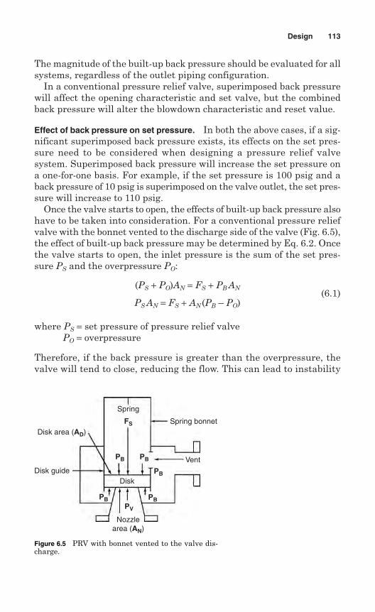
The magnitude of the built-up back pressure should be evaluated for allsystems, regardless of the outlet piping configuration.
In a conventional pressure relief valve, superimposed back pressurewill affect the opening characteristic and set valve, but the combinedback pressure will alter the blowdown characteristic and reset value.
Effect of back pressure on set pressure. In both the above cases, if a sig-nificant superimposed back pressure exists, its effects on the set pres-sure need to be considered when designing a pressure relief valvesystem. Superimposed back pressure will increase the set pressure ona one-for-one basis. For example, if the set pressure is 100 psig and aback pressure of 10 psig is superimposed on the valve outlet, the set pres-sure will increase to 110 psig.
Once the valve starts to open, the effects of built-up back pressure alsohave to be taken into consideration. For a conventional pressure reliefvalve with the bonnet vented to the discharge side of the valve (Fig. 6.5),the effect of built-up back pressure may be determined by Eq. 6.2. Oncethe valve starts to open, the inlet pressure is the sum of the set pres-sure PS and the overpressure PO:
(PS + PO)AN = FS + PB AN
PS AN = FS + AN (PB – PO)(6.1)
where PS = set pressure of pressure relief valvePO = overpressure
Therefore, if the back pressure is greater than the overpressure, thevalve will tend to close, reducing the flow. This can lead to instability
Design 113
Disk area (AD)
Disk guide
Nozzlearea (AN)
Vent
Disk
Spring bonnet
Spring
FS
PB PB
PB
PBPBPV
Figure 6.5 PRV with bonnet vented to the valve dis-charge.
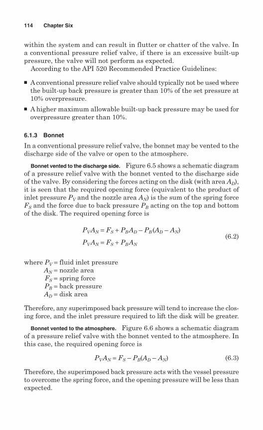
within the system and can result in flutter or chatter of the valve. Ina conventional pressure relief valve, if there is an excessive built-uppressure, the valve will not perform as expected.
According to the API 520 Recommended Practice Guidelines:
A conventional pressure relief valve should typically not be used wherethe built-up back pressure is greater than 10% of the set pressure at10% overpressure.
A higher maximum allowable built-up back pressure may be used foroverpressure greater than 10%.
6.1.3 Bonnet
In a conventional pressure relief valve, the bonnet may be vented to thedischarge side of the valve or open to the atmosphere.
Bonnet vented to the discharge side. Figure 6.5 shows a schematic diagramof a pressure relief valve with the bonnet vented to the discharge sideof the valve. By considering the forces acting on the disk (with area AD),it is seen that the required opening force (equivalent to the product ofinlet pressure PV and the nozzle area AN) is the sum of the spring forceFS and the force due to back pressure PB acting on the top and bottomof the disk. The required opening force is
PVAN = FS + PBAD – PB (AD – AN)
PVAN = FS + PBAN
(6.2)
where PV = fluid inlet pressureAN = nozzle areaFS = spring forcePB = back pressureAD = disk area
Therefore, any superimposed back pressure will tend to increase the clos-ing force, and the inlet pressure required to lift the disk will be greater.
Bonnet vented to the atmosphere. Figure 6.6 shows a schematic diagramof a pressure relief valve with the bonnet vented to the atmosphere. Inthis case, the required opening force is
PVAN = FS – PB(AD – AN) (6.3)
Therefore, the superimposed back pressure acts with the vessel pressureto overcome the spring force, and the opening pressure will be less thanexpected.
114 Chapter Six
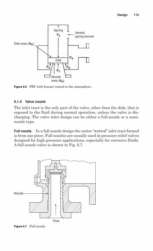
6.1.4 Valve nozzle
The inlet tract is the only part of the valve, other than the disk, that isexposed to the fluid during normal operation, unless the valve is dis-charging. The valve inlet design can be either a full-nozzle or a semi-nozzle type.
Full nozzle. In a full-nozzle design the entire “wetted” inlet tract formedis from one piece. Full nozzles are usually used in pressure relief valvesdesigned for high-pressure applications, especially for corrosive fluids.A full-nozzle valve is shown in Fig. 6.7.
Design 115
Disk area (AD)
SpringVentedspring bonnetFS
PB
PBPBPV
Disk
Nozzlearea (AN)
Figure 6.6 PRV with bonnet vented to the atmosphere.
Flow
Nozzle
Figure 6.7 Full nozzle.
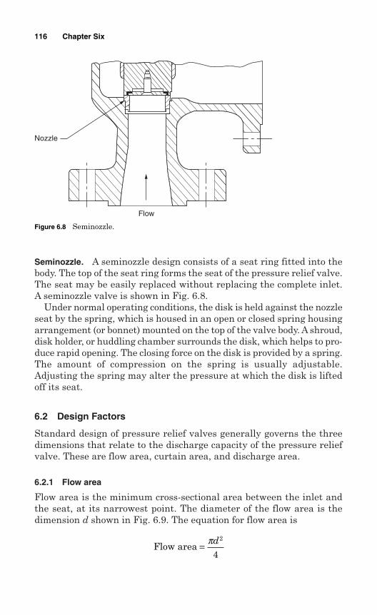
Seminozzle. A seminozzle design consists of a seat ring fitted into thebody. The top of the seat ring forms the seat of the pressure relief valve.The seat may be easily replaced without replacing the complete inlet.A seminozzle valve is shown in Fig. 6.8.
Under normal operating conditions, the disk is held against the nozzleseat by the spring, which is housed in an open or closed spring housingarrangement (or bonnet) mounted on the top of the valve body. A shroud,disk holder, or huddling chamber surrounds the disk, which helps to pro-duce rapid opening. The closing force on the disk is provided by a spring.The amount of compression on the spring is usually adjustable.Adjusting the spring may alter the pressure at which the disk is liftedoff its seat.
6.2 Design Factors
Standard design of pressure relief valves generally governs the threedimensions that relate to the discharge capacity of the pressure reliefvalve. These are flow area, curtain area, and discharge area.
6.2.1 Flow area
Flow area is the minimum cross-sectional area between the inlet andthe seat, at its narrowest point. The diameter of the flow area is thedimension d shown in Fig. 6.9. The equation for flow area is
Flow area = πd2
4
116 Chapter Six
Flow
Nozzle
Figure 6.8 Seminozzle.
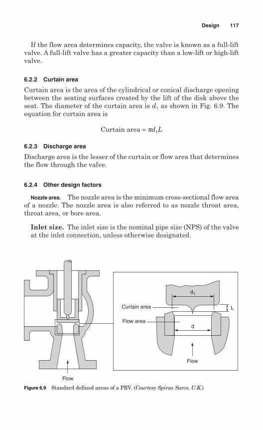
If the flow area determines capacity, the valve is known as a full-liftvalve. A full-lift valve has a greater capacity than a low-lift or high-liftvalve.
6.2.2 Curtain area
Curtain area is the area of the cylindrical or conical discharge openingbetween the seating surfaces created by the lift of the disk above theseat. The diameter of the curtain area is d1 as shown in Fig. 6.9. Theequation for curtain area is
Curtain area = pd1L
6.2.3 Discharge area
Discharge area is the lesser of the curtain or flow area that determinesthe flow through the valve.
6.2.4 Other design factors
Nozzle area. The nozzle area is the minimum cross-sectional flow areaof a nozzle. The nozzle area is also referred to as nozzle throat area,throat area, or bore area.
Inlet size. The inlet size is the nominal pipe size (NPS) of the valveat the inlet connection, unless otherwise designated.
Design 117
Flow
Flow
L
d
d1
Curtain area
Flow area
Figure 6.9 Standard defined areas of a PRV. (Courtesy Spirax Sarco, U.K.)
Discharge size. The discharge size is the nominal pipe size (NPS)of the valve at the discharge connection, unless otherwise designated.
Lift. The lift is the actual travel of the disk from the closed positionwhen a valve is relieving.
Coefficient of discharge. The coefficient of discharge is the ratio of themass flow rate in a valve to that of an ideal nozzle. It is used for calcu-lation of flow through a pressure relief device. There are two types ofcoefficient of discharge:
1. The effective coefficient of discharge. The effective coefficient of dis-charge is a nominal value used with an effective discharge area tocalculate the minimum required relieving capacity of a pressurerelief valve.
2. The rated coefficient of discharge. The rated coefficient of dischargeis determined in accordance with the applicable code or regulationand is used with the actual discharge area for calculation of the ratedflow capacity of a pressure relief valve.
6.3 Pressure Requirements
A pressure-level relationship for pressure relief valves according toAPI 520 Recommended Practice is shown in Fig. 6.10. The features are:
The figure conforms with the requirements of ASME Sec. VIII—Unfired Pressure Vessel Code for maximum allowable working pres-sure (MAWP) greater than 30 psi.
The pressure conditions shown are for pressure relief valves installedon a pressure vessel.
Allowable set-pressure tolerances will be in accordance with the appli-cable codes.
The MAWP is equal to or greater than the design pressure for a coin-cident design temperature.
The operating pressure may be higher or lower than 90 psi. Appendix M of Sec. VIII, Division I, should be referred to for guidance
on blowdown and pressure differentials.
6.3.1 System pressures
Maximum operating pressure. Maximum operating pressure is the max-imum pressure expected during system operation.
118 Chapter Six
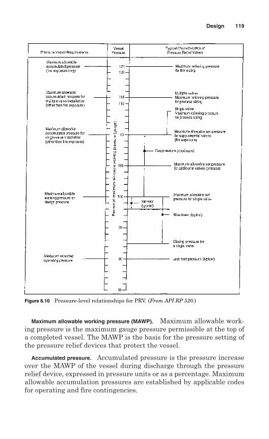
Maximum allowable working pressure (MAWP). Maximum allowable work-ing pressure is the maximum gauge pressure permissible at the top ofa completed vessel. The MAWP is the basis for the pressure setting ofthe pressure relief devices that protect the vessel.
Accumulated pressure. Accumulated pressure is the pressure increaseover the MAWP of the vessel during discharge through the pressurerelief device, expressed in pressure units or as a percentage. Maximumallowable accumulation pressures are established by applicable codesfor operating and fire contingencies.
Design 119
Figure 6.10 Pressure-level relationships for PRV. (From API RP 520.)
Rated relieving capacity. Rated relieving capacity is the measured reliev-ing capacity permitted by the applicable code or regulation to be usedas a basis for the application of a pressure relief device.
Stamped capacity. Stamped capacity is the rated relieving capacity thatappears on the device nameplate. The stamped capacity is based on theset pressure or burst pressure plus the allowable overpressure for com-pressible fluids and the differential pressure for incompressible fluids.
6.3.2 Relieving device pressures
Set pressure. Set pressure is the inlet gauge pressure at which thepressure relief valve is set to open under service conditions.
Blowdown. Blowdown is the difference between the set pressure andthe closing pressure of a pressure relief valve, expressed as a percent-age of the set pressure or in pressure units.
Overpressure. Overpressure is the pressure increase over the set pres-sure of the relieving device, expressed in pressure units or as a per-centage. It is the same accumulation when the relieving device is set atthe MAWP of the vessel and there are no inlet pipe losses to the reliev-ing device.
Opening pressure. Opening pressure is the value of increasing inletstatic pressure at which there is a measurable lift of the disk or at whichdischarge of the fluid becomes continuous.
Closing pressure. Closing pressure is the value of decreasing inlet staticpressure at which the valve disk reestablishes contact with the seat orat which lift becomes zero.
Simmer. Simmer is the audible or visible escape of compressible fluidbetween the seat and the disk at an inlet static pressure below the setpressure and at no measurable capacity.
Leak-test pressure. Leak-test pressure is the specified inlet static pres-sure at which a seat leak test is performed.
6.4 Design Considerations
The main purpose of designing a pressure relief valve is to prevent pres-sure in the system being protected from increasing beyond safe designlimits. The other purpose of a pressure relief valve is to minimizedamage to other system components due to operation of the PRV itself.
The following design features should be considered when designinga pressure relief valve:
120 Chapter Six
Leakage at system operating pressure is within acceptable standardsof performance.
Opens at specified set pressure, within tolerance. Relieves the process products in a controlled manner. Closes at specified reseat pressure. Easy to maintain, adjust, and verify settings. Cost-effective maintenance with minimal downtime and spare parts
investment.
Mechanical loads for both the closed and open (full discharge) posi-tions should be considered in concurrence with the service conditions.The pressure relief valves have extended structures and these structuresare necessary to maintain pressure integrity.
Earthquake loadings for the piping system or vessel nozzle should beconsidered. An analysis may be performed based on static forces result-ing from equivalent earthquake acceleration acting as the center ofgravity of the extended masses. Classical bending and direct stressequations may be used for such an analysis.
6.5 Design of Parts
Parts of the pressure relief valves are designed in accordance with thecode requirements of the American Society of Mechanical Engineers(AMSE) and American Petroleum Institute (API). A designer shouldconform that all the parts meet the code requirements so that completepressure relief valves can be stamped with code symbols.
6.5.1 Body
The design of the valve body should take into consideration the inletflange connection, the outer flange connection, and the body structuralconfiguration. The bonnet design should follow the body design if theoutlet flange is an extension of the bonnet.
6.5.2 Bonnet
A bonnet is a component used on a direct spring valve or on a pilot in apilot-operated valve that supports the spring. The bonnet may or maynot contain pressure.
6.5.3 Nozzle
A nozzle is a primary pressure containing component in a pressure reliefvalve that forms a part of the inlet flow passage.
Design 121
6.5.4 Disk
A disk is a movable component of a pressure relief valve that containsthe primary pressure when it rests against the nozzle.
6.5.5 Spindle
A spindle is a part whose axial orientation is parallel to the travel of thedisk. The spindle may be used for the following applications:
Assist in alignment Guide disk travel, and Transfer of internal or external forces to the seats.
6.5.6 Adjusting ring
An adjusting ring is a ring assembled to the nozzle or guide of a directspring valve used to control the opening characteristics or the reseatpressure.
6.5.7 Adjusting screw
An adjusting screw is a screw used to adjust the set pressure or the resetpressure of a pressure relief valve.
6.5.8 Huddling chamber
A huddling chamber is the annular pressure chamber between the nozzleexit and the disk or disk holder which produces the lifting force to obtaina pop action.
6.5.9 Spring
A spring is the element in a pressure relief valve that provides the forceto keep the disk on the nozzle. The valve spring is designed in such away that the full-lift spring compression should not be greater than80% of the nominal solid deflection. The permanent set of the springshould not exceed 0.5% of the free height.
The permanent set of the spring is defined as the difference betweenthe free height measured a minimum of 10 min after the spring hasbeen compressed solid three additional times after presetting at roomtemperature.
6.6 Testing and Marking
Each pressure relief valve to which code symbol stamp is to be appliedshould be tested by the manufacturer or assembler. Once construction iscompleted, the valves should be tested and marked according to the code.
122 Chapter Six
6.6.1 Hydrostatic Test
Hydrostatic testing should be performed after assembly of the valve inaccordance with the provision of the code. The primary pressure partsshould be tested at a pressure of at least 1.5 times the design pressureof the parts. The secondary pressure zones of each closed bonnet valveshould be tested with air or other gas at a pressure of at least 30 psi.The test results should no show any visible sign of leakage.
6.6.2 Marking
The valves shall be marked according to the requirements of the code.A manufacturer or assembler is required to mark pressure relief valvesin such a way that the marking will not be obliterated in service.
The following data, as a minimum, should be marked on the pressurerelief valves: name or an acceptable abbreviation of the manufacturer,manufacturer’s design or type number, set pressure (psig), blowdown(psi), certified capacity (SCFM or lb/min), lift of the valve (in.), yearbuilt, and code symbol stamp.
6.7 Rupture Disks
Rupture disks are nonreclosing pressure relief devices designed to pro-vide virtually instantaneous unrestricted pressure relief to a closedsystem at a predetermined pressure and coincident temperature.
Rupture disks can be specified for pressure relief requirements ofsystems with gas, vapor, or liquid. Also, rupture disks designs are avail-able for highly viscous fluids. The rupture disk for liquid service shouldbe carefully designed to ensure that design of the disk is suitable forliquid service.
The rupture disk is also a temperature-sensitive relief device. Burstpressure may vary significantly with the temperature of the rupture diskdevice. As the temperature at the disk increases, the burst pressureusually decreases. For this reason, the rupture disk should be designedfor the pressure and temperature at the disk is expected to burst.
6.7.1 Basic design
There are three main basic designs of rupture disks: (1) forward acting,tension loaded; (2) reverse acting, compression loaded; and (3) graphite,shear loaded.
Forward-acting rupture disks. Forward-acting rupture disks are designedto fail in tension (Fig. 6.11). When pressure applied to the concave sidereaches the point at which severe localized thinning of metal occurs, the
Design 123
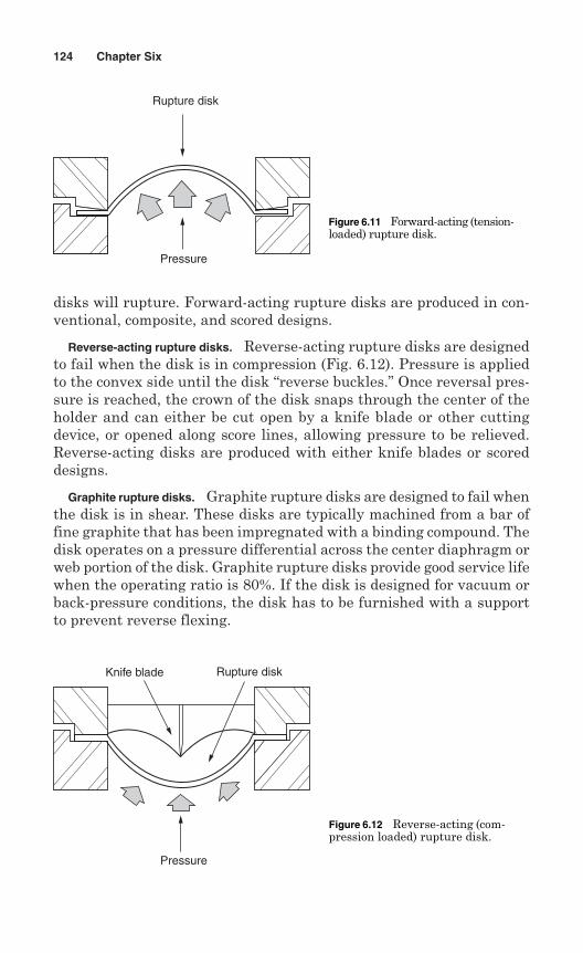
disks will rupture. Forward-acting rupture disks are produced in con-ventional, composite, and scored designs.
Reverse-acting rupture disks. Reverse-acting rupture disks are designedto fail when the disk is in compression (Fig. 6.12). Pressure is appliedto the convex side until the disk “reverse buckles.” Once reversal pres-sure is reached, the crown of the disk snaps through the center of theholder and can either be cut open by a knife blade or other cuttingdevice, or opened along score lines, allowing pressure to be relieved.Reverse-acting disks are produced with either knife blades or scoreddesigns.
Graphite rupture disks. Graphite rupture disks are designed to fail whenthe disk is in shear. These disks are typically machined from a bar offine graphite that has been impregnated with a binding compound. Thedisk operates on a pressure differential across the center diaphragm orweb portion of the disk. Graphite rupture disks provide good service lifewhen the operating ratio is 80%. If the disk is designed for vacuum orback-pressure conditions, the disk has to be furnished with a supportto prevent reverse flexing.
124 Chapter Six
Rupture disk
Pressure
Figure 6.11 Forward-acting (tension-loaded) rupture disk.
Knife blade Rupture disk
Pressure
Figure 6.12 Reverse-acting (com-pression loaded) rupture disk.
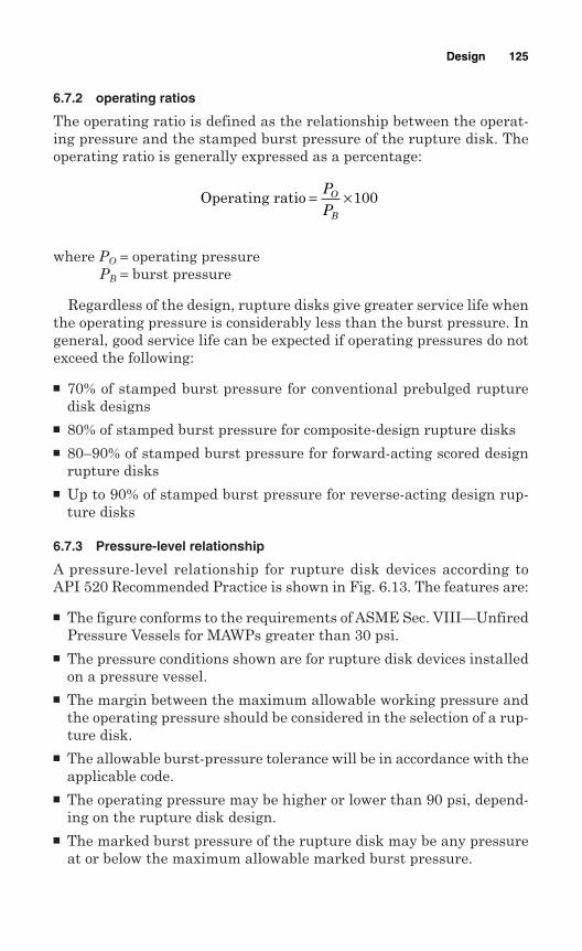
6.7.2 operating ratios
The operating ratio is defined as the relationship between the operat-ing pressure and the stamped burst pressure of the rupture disk. Theoperating ratio is generally expressed as a percentage:
where PO = operating pressurePB = burst pressure
Regardless of the design, rupture disks give greater service life whenthe operating pressure is considerably less than the burst pressure. Ingeneral, good service life can be expected if operating pressures do notexceed the following:
70% of stamped burst pressure for conventional prebulged rupturedisk designs
80% of stamped burst pressure for composite-design rupture disks 80–90% of stamped burst pressure for forward-acting scored design
rupture disks Up to 90% of stamped burst pressure for reverse-acting design rup-
ture disks
6.7.3 Pressure-level relationship
A pressure-level relationship for rupture disk devices according toAPI 520 Recommended Practice is shown in Fig. 6.13. The features are:
The figure conforms to the requirements of ASME Sec. VIII—UnfiredPressure Vessels for MAWPs greater than 30 psi.
The pressure conditions shown are for rupture disk devices installedon a pressure vessel.
The margin between the maximum allowable working pressure andthe operating pressure should be considered in the selection of a rup-ture disk.
The allowable burst-pressure tolerance will be in accordance with theapplicable code.
The operating pressure may be higher or lower than 90 psi, depend-ing on the rupture disk design.
The marked burst pressure of the rupture disk may be any pressureat or below the maximum allowable marked burst pressure.
Operating ratio = ×PP
O
B
100
Design 125
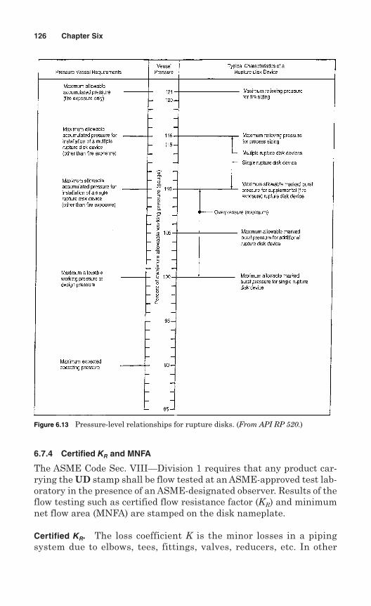
6.7.4 Certified KR and MNFA
The ASME Code Sec. VIII—Division 1 requires that any product car-rying the UD stamp shall be flow tested at an ASME-approved test lab-oratory in the presence of an ASME-designated observer. Results of theflow testing such as certified flow resistance factor (KR) and minimumnet flow area (MNFA) are stamped on the disk nameplate.
Certified KR. The loss coefficient K is the minor losses in a pipingsystem due to elbows, tees, fittings, valves, reducers, etc. In other
126 Chapter Six
Figure 6.13 Pressure-level relationships for rupture disks. (From API RP 520.)
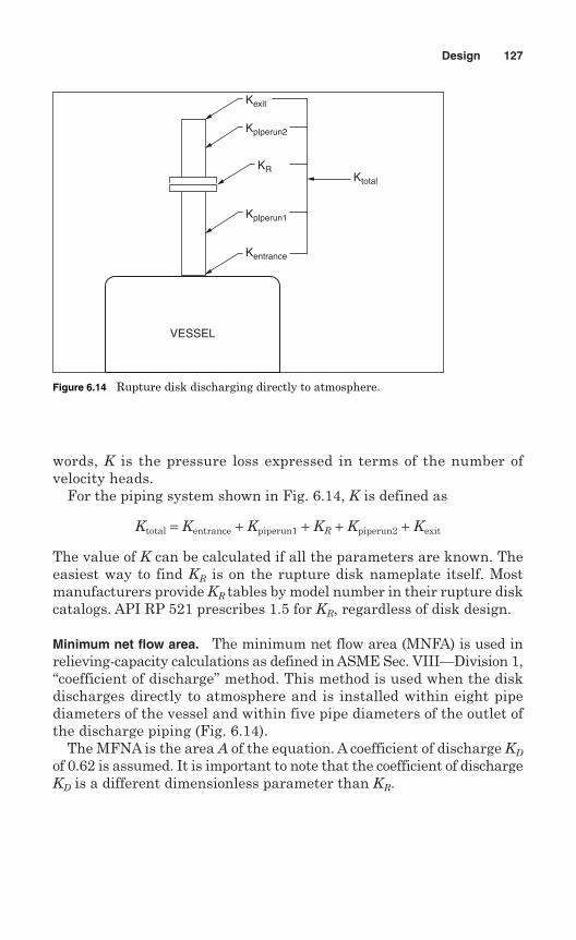
words, K is the pressure loss expressed in terms of the number ofvelocity heads.
For the piping system shown in Fig. 6.14, K is defined as
Ktotal = Kentrance + Kpiperun1 + KR + Kpiperun2 + Kexit
The value of K can be calculated if all the parameters are known. Theeasiest way to find KR is on the rupture disk nameplate itself. Mostmanufacturers provide KR tables by model number in their rupture diskcatalogs. API RP 521 prescribes 1.5 for KR, regardless of disk design.
Minimum net flow area. The minimum net flow area (MNFA) is used inrelieving-capacity calculations as defined in ASME Sec. VIII—Division 1,“coefficient of discharge” method. This method is used when the diskdischarges directly to atmosphere and is installed within eight pipediameters of the vessel and within five pipe diameters of the outlet ofthe discharge piping (Fig. 6.14).
The MFNA is the area A of the equation. A coefficient of discharge KD
of 0.62 is assumed. It is important to note that the coefficient of dischargeKD is a different dimensionless parameter than KR.
Design 127
Ktotal
Kexit
Kplperun2
KR
Kplperun1
Kentrance
VESSEL
Figure 6.14 Rupture disk discharging directly to atmosphere.

This page intentionally left blank
Chapter
7Manufacturing
Pressure relieving devices in the United States are manufactured inaccordance with the rules of the American Society of MechanicalEngineers (ASME) Boiler and Pressure Vessel Code. The manufac-turer is responsible for design, construction, quality control, andcapacity certification. A pressure relief device can be marked withthe ASME Code symbol stamp only if all the requirements of theASME Code are met.
Following are the ASME Code symbols for pressure relief devices:
V—safety valve for power boilers
HV—safety relief valve for heating boilers
NV—safety relief valve for nuclear components
TV— safety relief valve for transport tanks
UV—safety relief valve for pressure vessels
UD—rupture disks
TD—rupture disks for transport tanks
In foreign countries, pressure relieving devices are manufacturedaccording to the Code adopted by the respective countries. The manu-facturer is responsible for design, construction, quality control, andcapacity certification. Generally, the jurisdictional authority of a coun-try or inspection companies authorized by that jurisdiction provideinspection services during construction.
129
Copyright © 2006 by The McGraw-Hill Companies, Inc. Click here for terms of use.
7.1 Manufacture of Pressure Relief Valves
Pressure relief valves are manufactured by manufacturers or assem-blers, who must hold an ASME certification to use Code symbol stamps.
A manufacturer is defined as a person or organization that is respon-sible for design, material selection, capacity certification, manufacturerof all component parts, assembly, testing, sealing, and shipping of pres-sure reliving valves as required by various sections of the ASME Boilerand Pressure Vessel Code.
An assembler is defined as a person or organization that purchasesor receives from a manufacturer the necessary components or valves andassemblies, adjusts, tests, seals, and ships pressure relieving valvescertified in accordance with the ASME Boiler and Pressure Vessel Codeat a geographic location other than that of the manufacturer and usingfacilities other than those used by the manufacturer.
A manufacturer is required to establish a quality control system formanufacturing pressure relief valves. The manufacturer has to demon-strate to the ASME designee that the manufacturing, production, andtest facilities and quality control procedures as described in the qualitycontrol system ensure close performance between the production sam-ples and the valves submitted for capacity certification. An ASMEdesignee can inspect the manufacturing, assembly, and test operationsat any time.
A Certificate of Authorization to apply ASME Code symbol stamps(see Fig. 7.1 for the V symbol stamp and Fig. 7.2 for the UV symbolstamp), if granted by the ASME, remains valid for 3 years from the dateit is initially issued. This Certificate of Authorization may be extendedfor 3-year periods if the following tests are completed satisfactorilywithin 6 months before expiry date:
1. Two sample production pressure relief valves of a size and capacityselected by an ASME designee.
2. An ASME designee observes the operational and capacity tests at anASME-accepted laboratory.
An assembler can apply the ASME Code symbol for the use of unmodi-fied parts as per instructions of the valve manufacturer. The assembleris permitted to convert original finished parts by machining to other fin-ished parts, provided that:
1. Conversions are done according to either drawings or written instruc-tions or both, furnished by the manufacturer.
2. The assembler’s quality system is accepted by a representative froman ASME-designated organization.
130 Chapter Seven
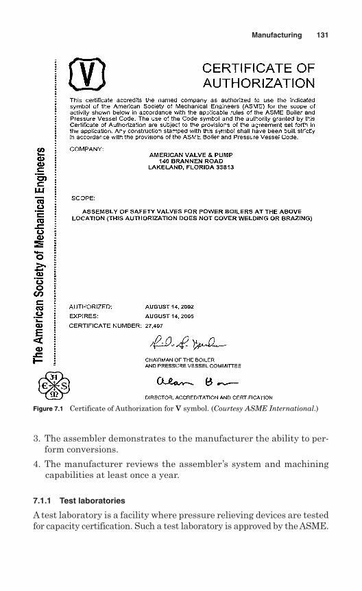
3. The assembler demonstrates to the manufacturer the ability to per-form conversions.
4. The manufacturer reviews the assembler’s system and machiningcapabilities at least once a year.
7.1.1 Test laboratories
A test laboratory is a facility where pressure relieving devices are testedfor capacity certification. Such a test laboratory is approved by the ASME.
Manufacturing 131
Figure 7.1 Certificate of Authorization for V symbol. (Courtesy ASME International.)
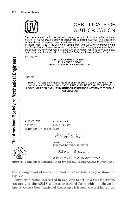
The arrangement of test equipment in a test laboratory is shown inFig. 7.3.
Any organization interested in applying to set-up a test laboratorycan apply to the ASME using a prescribed form, which is shown inApp. E. Once a Certification of Acceptance is issued, the test laboratory
132 Chapter Seven
Figure 7.2 Certificate of Authorization for UV symbol. (Courtesy ASME International.)
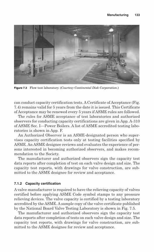
can conduct capacity certification tests. A Certificate of Acceptance (Fig.7.4) remains valid for 5 years from the date it is issued. This Certificateof Acceptance may be renewed every 5 years if ASME rules are followed.
The rules for ASME acceptance of test laboratories and authorizedobservers for conducting capacity certifications are given in App. A-310of ASME Sec. I—Power Boilers. A list of ASME accredited testing labo-ratories is shown in App. F.
An Authorized Observer is an ASME-designated person who super-vises capacity certification tests only at testing facilities specified byASME. An ASME designee reviews and evaluates the experience of per-sons interested in becoming authorized observers, and makes recom-mendation to the Society.
The manufacturer and authorized observers sign the capacity testdata reports after completion of test on each valve design and size. Thecapacity test reports, with drawings for valve construction, are sub-mitted to the ASME designee for review and acceptance.
7.1.2 Capacity certification
A valve manufacturer is required to have the relieving capacity of valvescertified before applying ASME Code symbol stamps to any pressurerelieving devices. The valve capacity is certified by a testing laboratoryaccredited by the ASME. A sample copy of the valve certificate publishedby the National Board Valve Testing Laboratory is shown in Fig. 7.5.
The manufacturer and authorized observers sign the capacity testdata reports after completion of tests on each valve design and size. Thecapacity test reports, with drawings for valve construction, are sub-mitted to the ASME designee for review and acceptance.
Manufacturing 133
Figure 7.3 Flow test laboratory. (Courtesy Continental Disk Corporation.)
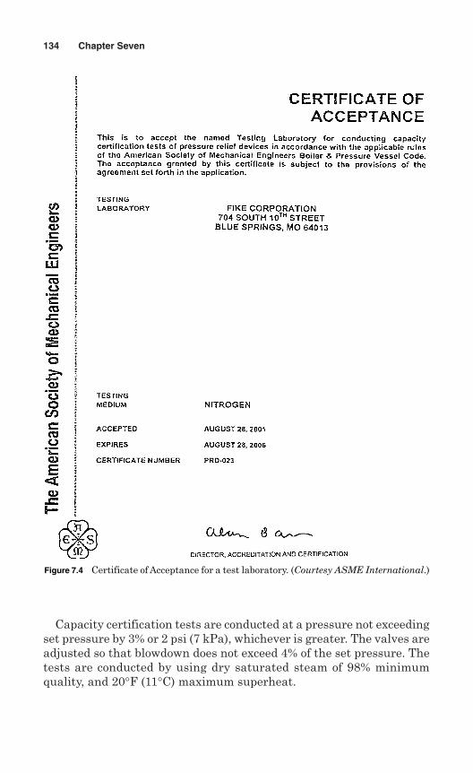
Capacity certification tests are conducted at a pressure not exceedingset pressure by 3% or 2 psi (7 kPa), whichever is greater. The valves areadjusted so that blowdown does not exceed 4% of the set pressure. Thetests are conducted by using dry saturated steam of 98% minimumquality, and 20°F (11°C) maximum superheat.
134 Chapter Seven
Figure 7.4 Certificate of Acceptance for a test laboratory. (Courtesy ASME International.)
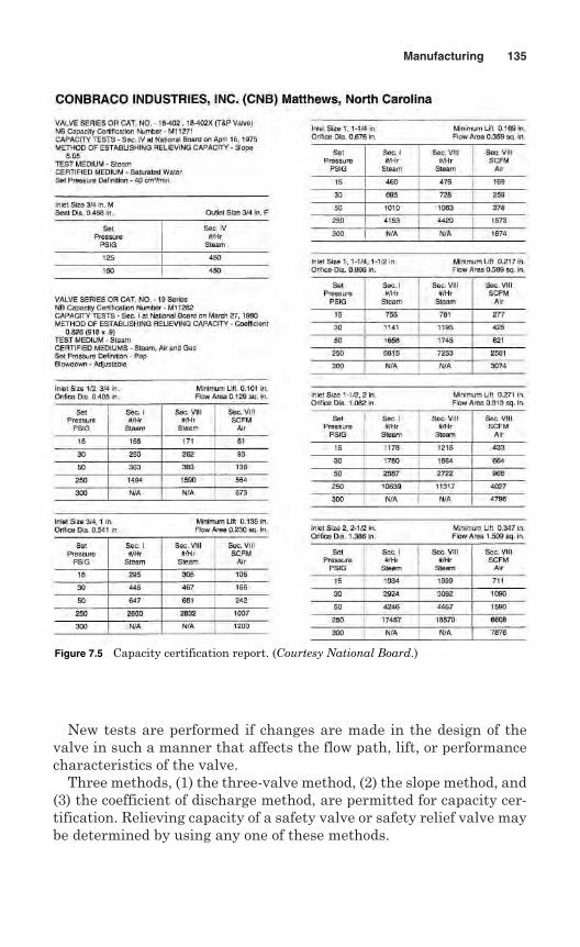
New tests are performed if changes are made in the design of thevalve in such a manner that affects the flow path, lift, or performancecharacteristics of the valve.
Three methods, (1) the three-valve method, (2) the slope method, and(3) the coefficient of discharge method, are permitted for capacity cer-tification. Relieving capacity of a safety valve or safety relief valve maybe determined by using any one of these methods.
Manufacturing 135
Figure 7.5 Capacity certification report. (Courtesy National Board.)
Three-valve method. In the three-valve method, a set of three valves foreach combination of size, design, and pressure setting is tested. On test,the capacity should stay within the range of ±5% of the average capac-ity. If the test fails for one valve, it is required to be replaced with twovalves. Now a new average capacity of four valves is calculated, andtested again. If the test result for a valve fails to fall within ±5% of thenew average, that valve design is rejected.
The rated relieving capacity for each combination of design, size, andtest pressure is required to be 90% of the average capacity.
Slope method. In the slope method, a set of four valves for each com-bination of pipe size and orifice size is tested. The valves are set at pres-sures covering the range of pressures for which the valves will be usedor the range of pressures available at the testing laboratory. The capac-ities are determined according to the following.
The slope W/P of the measured capacity versus the flow pressure foreach test is calculated on average:
The values obtained from the testing are required to stay within ±5%of the average value:
Minimum slope = 0.95 × average slope
Maximum slope = 1.05 × average slope
The Authorized Observer is required to witness testing of additionalvalves at the rate of two for each valve if the values from the testing donot fall within the above minimum and maximum slope values.
Rated relieving capacity must not exceed 90% of the average slopetimes the absolute accumulation pressure:
Rated slope = 0.90 × average slope
The stamped capacity ≤ rated slope (1.03 × set pressure + 14.7) or (setpressure + 2 psi + 14.7), whichever is greater.
Coefficient of discharge method. In the coefficient of discharge method,a coefficient of discharge, K, is established for a specific valve design. Themanufacturer is required to submit at least three valves for each of threedifferent sizes, a total of nine valves, for testing. Each valve is set at adifferent pressure covering the range of pressure for which the valves willbe used or the range of pressures available at the test laboratory. The test
Slopemeasured capacity
absolute flow rating pressure, psia= =W
P
136 Chapter Seven
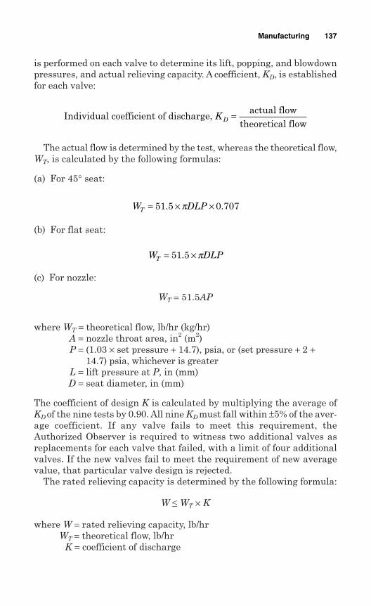
is performed on each valve to determine its lift, popping, and blowdownpressures, and actual relieving capacity. A coefficient, KD, is establishedfor each valve:
The actual flow is determined by the test, whereas the theoretical flow,WT, is calculated by the following formulas:
(a) For 45° seat:
(b) For flat seat:
(c) For nozzle:
WT = 51.5AP
where WT = theoretical flow, lb/hr (kg/hr)A = nozzle throat area, in2 (m2)P = (1.03 × set pressure + 14.7), psia, or (set pressure + 2 +
14.7) psia, whichever is greaterL = lift pressure at P, in (mm)D = seat diameter, in (mm)
The coefficient of design K is calculated by multiplying the average ofKD of the nine tests by 0.90. All nine KD must fall within ±5% of the aver-age coefficient. If any valve fails to meet this requirement, theAuthorized Observer is required to witness two additional valves asreplacements for each valve that failed, with a limit of four additionalvalves. If the new valves fail to meet the requirement of new averagevalue, that particular valve design is rejected.
The rated relieving capacity is determined by the following formula:
W ≤ WT × K
where W = rated relieving capacity, lb/hrWT = theoretical flow, lb/hr
K = coefficient of discharge
W DLPT = ×51 5. π
W DLPT = × ×51 5 0 707. .π
Individual coefficient of discharge, actual flow
theoretical flowKD =
Manufacturing 137
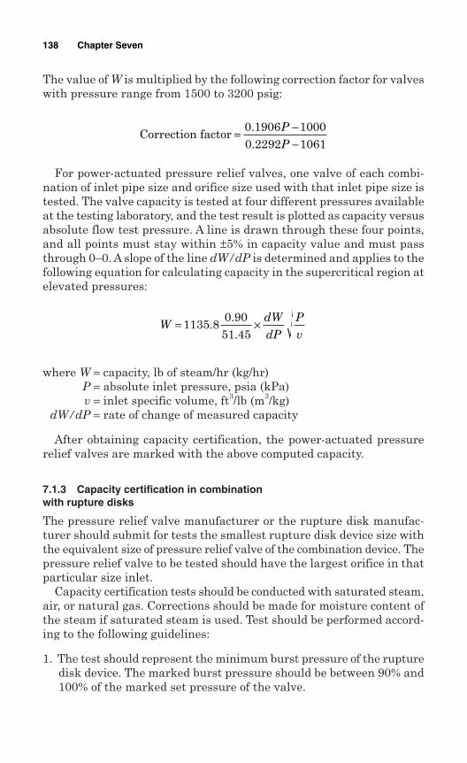
The value of W is multiplied by the following correction factor for valveswith pressure range from 1500 to 3200 psig:
For power-actuated pressure relief valves, one valve of each combi-nation of inlet pipe size and orifice size used with that inlet pipe size istested. The valve capacity is tested at four different pressures availableat the testing laboratory, and the test result is plotted as capacity versusabsolute flow test pressure. A line is drawn through these four points,and all points must stay within ±5% in capacity value and must passthrough 0–0. A slope of the line dW/dP is determined and applies to thefollowing equation for calculating capacity in the supercritical region atelevated pressures:
where W = capacity, lb of steam/hr (kg/hr)P = absolute inlet pressure, psia (kPa)v = inlet specific volume, ft3/lb (m3/kg)
dW/dP = rate of change of measured capacity
After obtaining capacity certification, the power-actuated pressurerelief valves are marked with the above computed capacity.
7.1.3 Capacity certification in combinationwith rupture disks
The pressure relief valve manufacturer or the rupture disk manufac-turer should submit for tests the smallest rupture disk device size withthe equivalent size of pressure relief valve of the combination device. Thepressure relief valve to be tested should have the largest orifice in thatparticular size inlet.
Capacity certification tests should be conducted with saturated steam,air, or natural gas. Corrections should be made for moisture content ofthe steam if saturated steam is used. Test should be performed accord-ing to the following guidelines:
1. The test should represent the minimum burst pressure of the rupturedisk device. The marked burst pressure should be between 90% and100% of the marked set pressure of the valve.
WdWdP
Pv
= ×1135 80 9051 45
...
Correction factor = −−
0 1906 10000 2292 1061..
PP
138 Chapter Seven
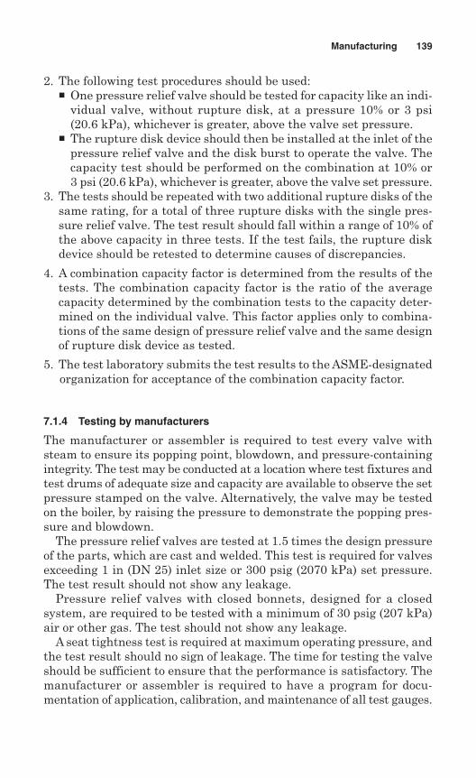
2. The following test procedures should be used: One pressure relief valve should be tested for capacity like an indi-
vidual valve, without rupture disk, at a pressure 10% or 3 psi(20.6 kPa), whichever is greater, above the valve set pressure.
The rupture disk device should then be installed at the inlet of thepressure relief valve and the disk burst to operate the valve. Thecapacity test should be performed on the combination at 10% or3 psi (20.6 kPa), whichever is greater, above the valve set pressure.
3. The tests should be repeated with two additional rupture disks of thesame rating, for a total of three rupture disks with the single pres-sure relief valve. The test result should fall within a range of 10% ofthe above capacity in three tests. If the test fails, the rupture diskdevice should be retested to determine causes of discrepancies.
4. A combination capacity factor is determined from the results of thetests. The combination capacity factor is the ratio of the averagecapacity determined by the combination tests to the capacity deter-mined on the individual valve. This factor applies only to combina-tions of the same design of pressure relief valve and the same designof rupture disk device as tested.
5. The test laboratory submits the test results to the ASME-designatedorganization for acceptance of the combination capacity factor.
7.1.4 Testing by manufacturers
The manufacturer or assembler is required to test every valve withsteam to ensure its popping point, blowdown, and pressure-containingintegrity. The test may be conducted at a location where test fixtures andtest drums of adequate size and capacity are available to observe the setpressure stamped on the valve. Alternatively, the valve may be testedon the boiler, by raising the pressure to demonstrate the popping pres-sure and blowdown.
The pressure relief valves are tested at 1.5 times the design pressureof the parts, which are cast and welded. This test is required for valvesexceeding 1 in (DN 25) inlet size or 300 psig (2070 kPa) set pressure.The test result should not show any leakage.
Pressure relief valves with closed bonnets, designed for a closedsystem, are required to be tested with a minimum of 30 psig (207 kPa)air or other gas. The test should not show any leakage.
A seat tightness test is required at maximum operating pressure, andthe test result should no sign of leakage. The time for testing the valveshould be sufficient to ensure that the performance is satisfactory. Themanufacturer or assembler is required to have a program for docu-mentation of application, calibration, and maintenance of all test gauges.
Manufacturing 139
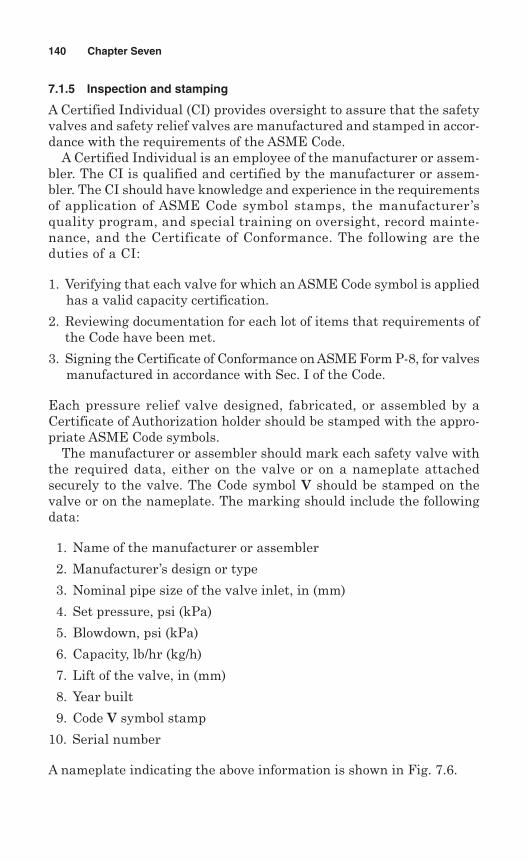
7.1.5 Inspection and stamping
A Certified Individual (CI) provides oversight to assure that the safetyvalves and safety relief valves are manufactured and stamped in accor-dance with the requirements of the ASME Code.
A Certified Individual is an employee of the manufacturer or assem-bler. The CI is qualified and certified by the manufacturer or assem-bler. The CI should have knowledge and experience in the requirementsof application of ASME Code symbol stamps, the manufacturer’squality program, and special training on oversight, record mainte-nance, and the Certificate of Conformance. The following are theduties of a CI:
1. Verifying that each valve for which an ASME Code symbol is appliedhas a valid capacity certification.
2. Reviewing documentation for each lot of items that requirements ofthe Code have been met.
3. Signing the Certificate of Conformance on ASME Form P-8, for valvesmanufactured in accordance with Sec. I of the Code.
Each pressure relief valve designed, fabricated, or assembled by aCertificate of Authorization holder should be stamped with the appro-priate ASME Code symbols.
The manufacturer or assembler should mark each safety valve withthe required data, either on the valve or on a nameplate attachedsecurely to the valve. The Code symbol V should be stamped on thevalve or on the nameplate. The marking should include the followingdata:
1. Name of the manufacturer or assembler
2. Manufacturer’s design or type
3. Nominal pipe size of the valve inlet, in (mm)
4. Set pressure, psi (kPa)
5. Blowdown, psi (kPa)
6. Capacity, lb/hr (kg/h)
7. Lift of the valve, in (mm)
8. Year built
9. Code V symbol stamp
10. Serial number
A nameplate indicating the above information is shown in Fig. 7.6.
140 Chapter Seven
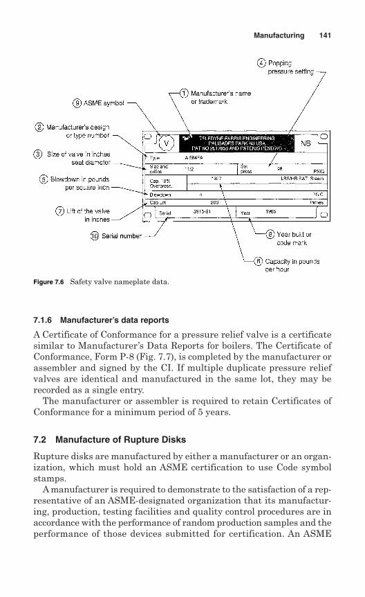
7.1.6 Manufacturer’s data reports
A Certificate of Conformance for a pressure relief valve is a certificatesimilar to Manufacturer’s Data Reports for boilers. The Certificate ofConformance, Form P-8 (Fig. 7.7), is completed by the manufacturer orassembler and signed by the CI. If multiple duplicate pressure reliefvalves are identical and manufactured in the same lot, they may berecorded as a single entry.
The manufacturer or assembler is required to retain Certificates ofConformance for a minimum period of 5 years.
7.2 Manufacture of Rupture Disks
Rupture disks are manufactured by either a manufacturer or an organ-ization, which must hold an ASME certification to use Code symbolstamps.
A manufacturer is required to demonstrate to the satisfaction of a rep-resentative of an ASME-designated organization that its manufactur-ing, production, testing facilities and quality control procedures are inaccordance with the performance of random production samples and theperformance of those devices submitted for certification. An ASME
Manufacturing 141
Figure 7.6 Safety valve nameplate data.
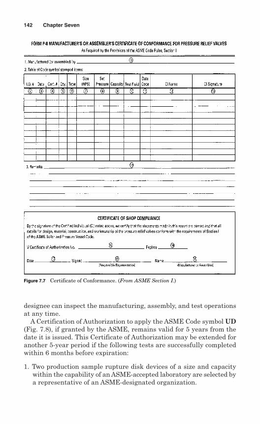
designee can inspect the manufacturing, assembly, and test operationsat any time.
A Certification of Authorization to apply the ASME Code symbol UD(Fig. 7.8), if granted by the ASME, remains valid for 5 years from thedate it is issued. This Certificate of Authorization may be extended foranother 5-year period if the following tests are successfully completedwithin 6 months before expiration:
1. Two production sample rupture disk devices of a size and capacitywithin the capability of an ASME-accepted laboratory are selected bya representative of an ASME-designated organization.
142 Chapter Seven
Figure 7.7 Certificate of Conformance. (From ASME Section I.)
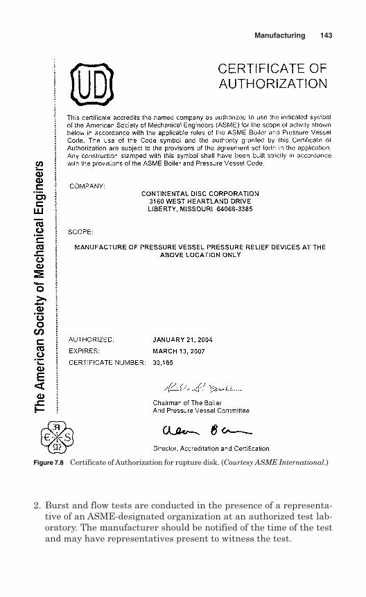
2. Burst and flow tests are conducted in the presence of a representa-tive of an ASME-designated organization at an authorized test lab-oratory. The manufacturer should be notified of the time of the testand may have representatives present to witness the test.
Manufacturing 143
Figure 7.8 Certificate of Authorization for rupture disk. (Courtesy ASME International.)
3. If any device fails to meet or exceed the performance (burst pres-sure, minimum net flow area, and flow resistance) requirements, thetest can be repeated at the rate of two replacement devices for eachdevice that failed.
4. If any replacement device fails to meet the performance require-ments, the authorization to use the Code symbol for that particulardevice may be revoked by the ASME within 60 days of the authori-zation. The manufacturer must demonstrate the cause of such fail-ure and the action taken within this period.
7.2.1 Manufacturing ranges
ASME Code Sec. VIII—Division I requires that the marked burst pres-sure of a disk (also referred to as set pressure) should not exceed themaximum allowable working pressure (MAWP) of a pressure vesselwhen the disk is used as the primary or sole relief valve.
A customer may request to rupture the disk at a specified pressure.This pressure is called requested burst or rupture pressure. As the burstpressure of a disk is affected by temperature, the burst temperatureshould also be specified. The requested burst pressure is generally afunction of the equipment or system design pressure. Applicable codesand operating conditions should be considered when deciding requestedburst pressure.
The marked burst pressure always varies from the requested burstpressure. The amount of this variation is controlled by the manufac-turing range for the disk. A manufacturing range is permitted becauseit is not practical to manufacture rupture disks to an exact value. Therange of burst pressure depends on the type of disk, a typical range being+10% to –5% for standard and composite-type disks. The total manu-facturing range is always on the minus side for scored rupture disks.
The marked burst pressure is normally determined by bursting atleast two disks at the required temperature during the manufacturingprocess and determining the rupture disk rating. This burst pressuremay be anywhere within the specified manufacturing range. Therequested burst pressure should be specified in such a way that theupper end of the manufacturing ranges does not exceed the MAWP ofthe vessel or system.
7.2.2 Rupture tolerances
The ASME Code, Sec. VIII—Division I, also specifies rupture toler-ances. This tolerance is ±5% for pressure exceeding 40 psig, or ±2 psigfor pressure up to 40 psig. The manufacturer is required to guaranteethat the burst pressure of all rupture disks in a given lot is within this
144 Chapter Seven
tolerance from the marked burst pressure for compliance with the ASMECode requirements.
If the marked burst pressure is at or near the maximum of the man-ufacturing range due to the allowed ruptured tolerance, the actual burstpressure may exceed the MAWP. This situation is permissible under theASME Code.
7.2.3 Capacity certification
The manufacturer is required to have the relieving capacity of the rup-ture disk devices certified before stamping with Code symbol stampUD. The types of capacity certification are described below.
Individual rupture disks. The capacity certification for an individual rup-ture disk by the National Board is shown in Fig. 7.9.
Capacity of pressure relief valves in combination with a rupture disk deviceat the inlet. The pressure relief valve manufacturer or the rupture diskmanufacturer submits for tests the smallest rupture disk device sizewith the equivalent size of pressure relief valve of the combinationdevice. The pressure relief valve to be tested should have the largest ori-fice in that particular size inlet.
Capacity certification tests should be conducted with saturated steam,air, or natural gas. Corrections should be made for moisture content ofthe steam if saturated steam is used.
The test laboratory submits the test results to an ASME-designatedorganization for acceptance of the combination capacity factor.
Optional testing of rupture disk devices and pressure relief valves. A valvemanufacturer or a rupture disk manufacturer may conduct tests accord-ing to UG-132 using the next two larger sizes of the rupture disk deviceand pressure relief valve to determine a combination capacity factorapplicable to larger sizes. If established and certified, the combinationcapacity factor may be used for all larger sizes of the combination. Thecombination factor cannot be greater than 1.
If desired, additional tests may be conducted at higher pressures toestablish a maximum combination capacity factor for use at all higherpressures. However, the combination factor cannot be greater than 1.
Capacity of breaking pin devices in combination with pressure relief valves.Beaking pin devices in combination with pressure relief valves shouldbe tested in accordance with UG-131(d) or UG-131(e) as a combination.Capacity and Code symbol stamping should be based on the capacityestablished in accordance with these paragraphs.
Manufacturing 145
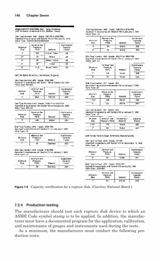
7.2.4 Production testing
The manufacturer should test each rupture disk device to which anASME Code symbol stamp is to be applied. In addition, the manufac-turer must have a documented program for the application, calibration,and maintenance of gauges and instruments used during the tests.
As a minimum, the manufacturer must conduct the following pro-duction tests:
146 Chapter Seven
Figure 7.9 Capacity certification for a rupture disk. (Courtesy National Board.)
1. The pressure parts of each rupture disk holder exceeding NPS 1(DN 25) inlet size or 300 psi (2070 kPa) design pressure should betested at a pressure of minimum 1.5 times the design pressure of theparts. There should not be any visible sign of leakage.
2. Sample rupture disks, selected from each lot of rupture disks, shouldbe made from the same material and size as those used in service.Each lot of rupture disks should be tested by one of the followingmethods:(a) A minimum of two sample rupture disks from each of rupture
disks should be burst at the specified temperature.(b) A minimum of four sample rupture disks, not less than 50% from
each lot, should be burst at four different temperatures over theapplicable temperature range for which the disks will be used.This data should be used to create a curve of burst pressureversus temperature for the lot of disks. The value of burst pres-sure should be derived from the curve for a specified temperature.
(c) A minimum of four sample rupture disks of prebulged solid metaldisks or graphite disks, using one size of disk from each lot ofmaterial, should be burst at four different temperatures coveringthe applicable temperature range. These data should be used forcreating a curve of percent change of burst pressures versus tem-perature for the lot of the material.
(d) A minimum of two disks from each lot of disks, made from thislot of material and of the same size, should be burst at the ambi-ent temperature to establish the room-temperature rating of thelot of disks. The percent change should be used to establish theburst pressure at the specified disk temperature for the lot ofdisks.
7.2.5 Marking
The manufacturer or assembler should mark each rupture disk withdata as required by the ASME Code. The data should be marked insuch a way that the marking will not be wiped out in service over aperiod of time.
The rupture disk marking may be placed on the flange of the disk oron a metal tag. The marking should include the following:
1. Name or identifying trademark of the manufacturer
2. Manufacturer’s design or type number
3. Lot number
4. Disk material
5. Size [NPS (DN) of rupture disk holder]
Manufacturing 147
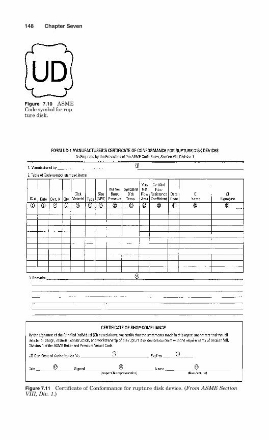
148 Chapter Seven
Figure 7.10 ASMECode symbol for rup-ture disk.
Figure 7.11 Certificate of Conformance for rupture disk device. (From ASME SectionVIII, Div. 1.)
6. Marked burst pressure, psi (kPa)
7. Specified disk temperature, °F (°C)
8. Minimum net flow area, in2 (mm2)
9. Certified flow resistance (as applicable):(a) KRG for rupture disk certified on air or gases; or(b) KRL for rupture disk certified on liquid; or(c) KRGL for rupture disk certified on air or gases, and liquid
10. ASME Code symbol as shown in Fig. 7.10.11. Year built; alternatively, a coding may be marked on the rupture disk
so that the disk manufacturer can identify the year the disk wasassembled and tested.
It is required that items 1, 2, and 5 above and flow direction also bemarked on the rupture disk holder.
7.2.6 Manufacturer’s data reports
Each rupture disk to which Code symbol UD will be applied must be fab-ricated or assembled by a manufacturer or assembler holding a validCertificate of Authorization from the ASME. A Certified Individual isrequired to provide oversight during fabrication of the rupture disks.
The data for each use of the Code symbol shall be documented onForm UD-1 Manufacturer’s or Assembler’s Certificate of Conformancefor Rupture Disk Devices, shown in Fig. 7.11.
Manufacturing 149

This page intentionally left blank
Chapter
8Sizing and Selection
A pressure relief device should be sized in such a manner that the pres-sure within the protected system cannot exceed the maximum allowableaccumulated pressure (MAAP). This means that a pressure relief deviceshould be sized so as to enable it to pass the required amount of fluidat the required pressure under all possible fault conditions. Once thetype of relief device has been established, along with its set pressure andits position in the system, the discharge capacity of the device has to becalculated. The required orifice area and nominal size can be deter-mined if the discharge capacity is known.
Pressure relief devices should be selected by engineers who have com-plete knowledge of the pressure relieving requirements of the system tobe protected and the environmental conditions. Selection should not bemade based on arbitrarily assumed conditions or incomplete informa-tion. Nowadays computer assisted programs are available for sizingand selection of pressure relief devices.
8.1 Pressure Relief Valves
Sizing of pressure relief valves involves calculating the required effec-tive area for the specific valve that will flow the required volume ofsystem fluid at anticipated relieving conditions.
Pressure relief valves are sized either by calculation or by selectionfrom a capacity chart according to the valve type and process fluid. Thecapacity chart is available in the manufacturer’s product catalog andsizing is self-explanatory. Generally, ASME and API formulas are usedfor sizing calculations.
Alternatively, Windows-based sizing programs for pressure reliefvalves can be used with the Windows operating systems. This program
151
Copyright © 2006 by The McGraw-Hill Companies, Inc. Click here for terms of use.
includes multi-lingual capability, the ability to save files in a standardWindows format, and the ability to print to any printer configured forthe Windows system. The printout options for each valve selectioninclude a datasheet, a drawing showing dimensions, weight, materi-als, the API designation, and a calculation sheet showing the appli-cable formula used in the area and capacity calculation. Each selectedvalve is completely configured to match the order entry, and name-plate designation. The program also includes the capabilities of copy-ing tag numbers, editing the selected valve options, and resizing tagnumbers.
This computer program is written based on the latest editions ofASME and API Codes. The program includes the checks for ASMESection VIII – Division 1 compliance, ASME B16.34 pressure tempera-ture limits, API pressure and temperature limits, O-ring and bellowsrequirements, spring chart limitations, and steam chart correlations.The output includes noise and reaction force calculation, outlines dimen-sional drawing (installation dimensions), bill of materials for valve com-ponent parts, and detailed valve selection criteria.
8.1.1 Valve sizes
Valve sizes are usually selected on the basis of orifice areas. TheAmerican Petroleum Institute (API) and the American Society ofMechanical Engineers (ASME) have devised standard equations that areused to size an orifice once the required relieving capacity has beendetermined. Once the required orifice has been determined then a stan-dard size orifice is selected from a list of standard orifice sizes availablefrom manufacturers.
The orifice areas are listed in API Standard 526. Valve manufactur-ers generally list their valves by inlet size, API letter designation fornozzle area, and outlet size. Manufacturers also provide ASME standardorifice sizes.
Table 8.1 shows the API and ASME letter designations for valves andtheir orifice areas.
The user can pick either API or ASME standard orifice sizes. Also,the user must pick orifice coefficients used to determine the requiredorifice. These orifice coefficients represent deviations from perfect dis-charge due to friction, viscosity, system backpressure, and multiplerelief devices used in combination. For a perfect discharge, all coeffi-cients would be one.
The actual ASME orifice size for a selected orifice is actually the sameorifice as the API, although they show two different sizes. ASME givesthe actual orifice size whereas API gives the “effective” orifice size.
152 Chapter Eight
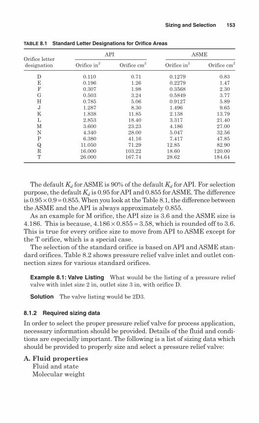
The default Kd for ASME is 90% of the default Kd for API. For selectionpurpose, the default Kd is 0.95 for API and 0.855 for ASME. The differenceis 0.95 × 0.9 = 0.855. When you look at the Table 8.1, the difference betweenthe ASME and the API is always approximately 0.855.
As an example for M orifice, the API size is 3.6 and the ASME size is4.186. This is because, 4.186 × 0.855 = 3.58, which is rounded off to 3.6.This is true for every orifice size to move from API to ASME except forthe T orifice, which is a special case.
The selection of the standard orifice is based on API and ASME stan-dard orifices. Table 8.2 shows pressure relief valve inlet and outlet con-nection sizes for various standard orifices.
Example 8.1: Valve Listing What would be the listing of a pressure reliefvalve with inlet size 2 in, outlet size 3 in, with orifice D.
Solution The valve listing would be 2D3.
8.1.2 Required sizing data
In order to select the proper pressure relief valve for process application,necessary information should be provided. Details of the fluid and condi-tions are especially important. The following is a list of sizing data whichshould be provided to properly size and select a pressure relief valve:
A. Fluid propertiesFluid and stateMolecular weight
Sizing and Selection 153
TABLE 8.1 Standard Letter Designations for Orifice Areas
Orifice letterAPI ASME
designation Orifice in2 Orifice cm2 Orifice in2 Orifice cm2
D 0.110 0.71 0.1279 0.83E 0.196 1.26 0.2279 1.47F 0.307 1.98 0.3568 2.30G 0.503 3.24 0.5849 3.77H 0.785 5.06 0.9127 5.89J 1.287 8.30 1.496 9.65K 1.838 11.85 2.138 13.79L 2.853 18.40 3.317 21.40M 3.600 23.23 4.186 27.00N 4.340 28.00 5.047 32.56P 6.380 41.16 7.417 47.85Q 11.050 71.29 12.85 82.90R 16.000 103.22 18.60 120.00T 26.000 167.74 28.62 184.64
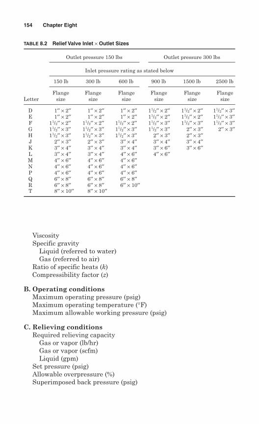
ViscositySpecific gravity
Liquid (referred to water)Gas (referred to air)
Ratio of specific heats (k)Compressibility factor (z)
B. Operating conditionsMaximum operating pressure (psig)Maximum operating temperature (°F)Maximum allowable working pressure (psig)
C. Relieving conditionsRequired relieving capacity
Gas or vapor (lb/hr)Gas or vapor (scfm)Liquid (gpm)
Set pressure (psig)Allowable overpressure (%)Superimposed back pressure (psig)
154 Chapter Eight
TABLE 8.2 Relief Valve Inlet × Outlet Sizes
Outlet pressure 150 lbs Outlet pressure 300 lbs
Inlet pressure rating as stated below
150 lb 300 lb 600 lb 900 lb 1500 lb 2500 lb
Flange Flange Flange Flange Flange FlangeLetter size size size size size size
D 1′′ × 2′′ 1′′ × 2′′ 1′′ × 2′′ 11/2′′ × 2′′ 11/2′′ × 2′′ 11/2′′ × 3′′E 1′′ × 2′′ 1′′ × 2′′ 1′′ × 2′′ 11/2′′ × 2′′ 11/2′′ × 2′′ 11/2′′ × 3′′F 11/2′′ × 2′′ 11/2′′ × 2′′ 11/2′′ × 2′′ 11/2′′ × 3′′ 11/2′′ × 3′′ 11/2′′ × 3′′G 11/2′′ × 3′′ 11/2′′ × 3′′ 11/2′′ × 3′′ 11/2′′ × 3′′ 2′′ × 3′′ 2′′ × 3′′H 11/2′′ × 3′′ 11/2′′ × 3′′ 11/2′′ × 3′′ 2′′ × 3′′ 2′′ × 3′′J 2′′ × 3′′ 2′′ × 3′′ 3′′ × 4′′ 3′′ × 4′′ 3′′ × 4′′K 3′′ × 4′′ 3′′ × 4′′ 3′′ × 4′′ 3′′ × 6′′ 3′′ × 6′′L 3′′ × 4′′ 3′′ × 4′′ 4′′ × 6′′ 4′′ × 6′′M 4′′ × 6′′ 4′′ × 6′′ 4′′ × 6′′N 4′′ × 6′′ 4′′ × 6′′ 4′′ × 6′′P 4′′ × 6′′ 4′′ × 6′′ 4′′ × 6′′Q 6′′ × 8′′ 6′′ × 8′′ 6′′ × 8′′R 6′′ × 8′′ 6′′ × 8′′ 6′′ × 10′′T 8′′ × 10′′ 8′′ × 10′′
(Specify constant or variable)Built-up back pressure (psig)Relieving temperature (°F)
8.1.3 API sizing
API RP 520 has established the rules for sizing of pressure reliefvalves. This recommended practice has addressed only flanged spring-loaded and pilot-operated safety valves with a D-T orifice. Valvessmaller or larger than those with D-T orifices are not addressed by APIRP 520.
The rules and equations of API RP 520 are intended for the estima-tion of pressure relief device requirements only. Manufacturers mayhave their own criteria, such as for discharge coefficients and correctionfactors, that are different from those listed in API RP 520. Final selec-tion of a pressure relief device is made by using the manufacturer’s spe-cific parameters, which are based on actual testing.
It is practice to size and select pressure relief valves as per API RP526 for gas, vapor, and steam service using the API RP 520 Kd value of0.975 and the effective areas of API RP 526. Although the API Kd valuesexceed the ASME-certified K values, the ASME-certified areas exceedthe effective areas of API RP 526, with the product of ASME-certified Kand area exceeding the product of API RP 520 Kd and API RP 526 effec-tive areas.
The value of K is established at the time valves are certified by theASME and are published for all ASME-certified valves in “PressureRelief Device Certifications” by the National Board.
Pressure relief valves are selected on the basis of their ability to meetan expected relieving condition and flowing a sufficient amount of fluidto prevent excessive pressure increase. The following steps are used forsizing pressure relief valves:
Step 1. Establish a set pressure at which the valve is to operate. Thisset pressure is determined based on the pressure limit of the systemand the applicable code.
Step 2. Determine the size of the valve orifice.
Step 3. Select a valve size that will flow the required relieving capac-ity when set at the pressure determined in step 1.
Step 4. Add accessories and options.
Sizing by calculation of the orifice area from a known required capac-ity is given in API Standard API-520, Part 1—Sizing and Selection ofPressure Relief Devices.
Sizing and Selection 155
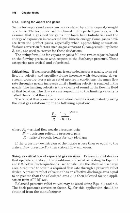
8.1.4 Sizing for vapors and gases
Sizing for vapors and gases can be calculated by either capacity weightor volume. The formulas used are based on the perfect gas laws, whichassume that a gas neither gains nor loses heat (adiabatic) and theenergy of expansion is converted into kinetic energy. Some gases devi-ate from the perfect gases, especially when approaching saturation.Various correction factors such as gas constant C, compressibility factorZ, etc., are used to correct for these deviations.
The sizing formulas for vapors or gases fall into two categories basedon the flowing pressure with respect to the discharge pressure. Thesecategories are: critical and subcritical.
Critical flow. If a compressible gas is expanded across a nozzle, or an ori-fice, its velocity and specific volume increase with decreasing down-stream pressure. For a given set of upstream conditions, the mass flowrate through a nozzle increases until a limiting velocity is reached in thenozzle. The limiting velocity is the velocity of sound in the flowing fluidat that location. The flow rate corresponding to the limiting velocity iscalled the critical flow rate.
The critical flow pressure ratio in absolute units is estimated by usingthe ideal gas relationship in the following equation:
where Pcf = critical flow nozzle pressure, psiaP1 = upstream relieving pressure, psiaK = ratio of specific heats for any ideal gas
If the pressure downstream of the nozzle is less than or equal to thecritical flow pressure Pcf, then critical flow will occur.
Sizing for critical flow of vapor and gas services. Pressure relief devicesthat operate at critical flow conditions are sized according to Eqs. 8.1and 8.2, below. Each equation is used to calculate the effective dischargearea A required to obtain a required flow rate through a pressure reliefdevice. A pressure relief valve that has an effective discharge area equalto or greater than the calculated area A is then selected for the appli-cation from API RP 526.
Balanced pressure relief valves may be sized using Eqs. 8.1 and 8.2.The back-pressure correction factor, Kb, for this application should beobtained from the manufacturer.
P
P Kcf
k k
1
12
1=
+
−/( )
156 Chapter Eight
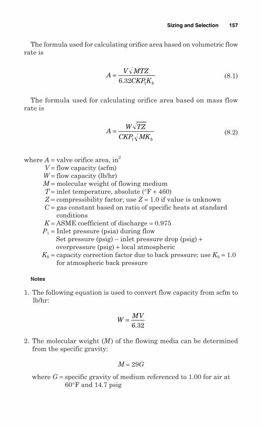
The formula used for calculating orifice area based on volumetric flowrate is
(8.1)
The formula used for calculating orifice area based on mass flowrate is
(8.2)
where A = valve orifice area, in2
V = flow capacity (scfm)W = flow capacity (lb/hr)M = molecular weight of flowing mediumT = inlet temperature, absolute (°F + 460)Z = compressibility factor; use Z = 1.0 if value is unknownC = gas constant based on ratio of specific heats at standard
conditionsK = ASME coefficient of discharge = 0.975
P1 = Inlet pressure (psia) during flowSet pressure (psig) – inlet pressure drop (psig) +overpressure (psig) + local atmospheric
Kb = capacity correction factor due to back pressure; use Kb = 1.0for atmospheric back pressure
Notes
1. The following equation is used to convert flow capacity from scfm tolb/hr:
2. The molecular weight (M ) of the flowing media can be determinedfrom the specific gravity:
M = 29G
where G = specific gravity of medium referenced to 1.00 for air at60°F and 14.7 psig
WMV=6 32.
AW TZ
CKP MKb
=1
AV MTZ
CKP Kb
=6 32 1.
Sizing and Selection 157
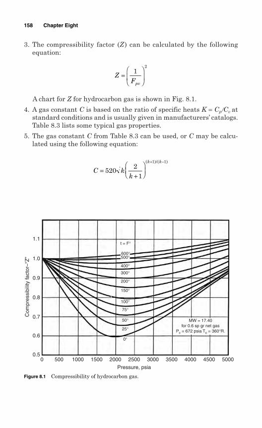
3. The compressibility factor (Z ) can be calculated by the followingequation:
A chart for Z for hydrocarbon gas is shown in Fig. 8.1.
4. A gas constant C is based on the ratio of specific heats K = Cp/Cv atstandard conditions and is usually given in manufacturers’ catalogs.Table 8.3 lists some typical gas properties.
5. The gas constant C from Table 8.3 can be used, or C may be calcu-lated using the following equation:
C kk
k k
=+
+ −
5202
1
1 1( )/( )
ZFpv
=
12
158 Chapter Eight
Figure 8.1 Compressibility of hydrocarbon gas.
0.50 500 1000 1500 2000 2500
Pressure, psia
3000 3500 4000
MW = 17.40for 0.6 sp gr net gas
Pc = 672 psia Tc = 360°R.
600°500°
400°
300°
200°
150°
100°
75°
50°
25°
0°
4500 5000
0.6
0.7
0.8
0.9
1.0
1.1
Com
pres
sibi
lity
fact
or–“
Z”
t = F°
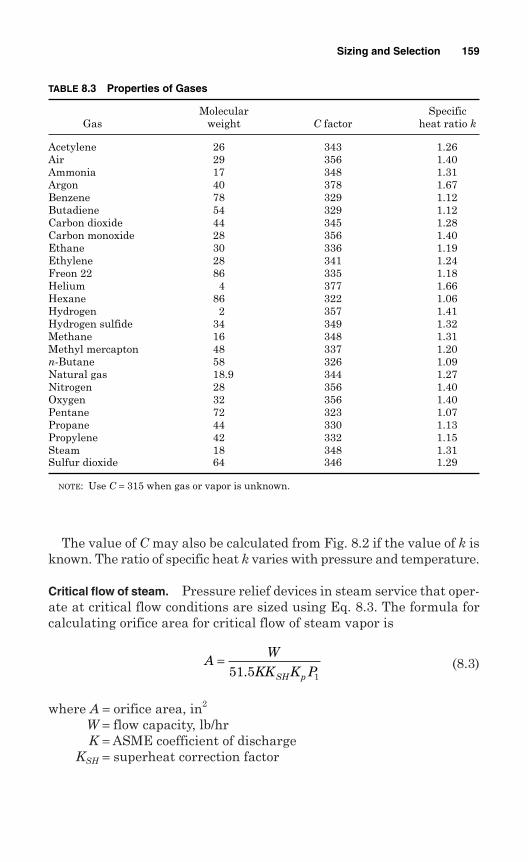
The value of C may also be calculated from Fig. 8.2 if the value of k isknown. The ratio of specific heat k varies with pressure and temperature.
Critical flow of steam. Pressure relief devices in steam service that oper-ate at critical flow conditions are sized using Eq. 8.3. The formula forcalculating orifice area for critical flow of steam vapor is
(8.3)
where A = orifice area, in2
W = flow capacity, lb/hrK = ASME coefficient of discharge
KSH = superheat correction factor
AW
KK K PSH p
=51 5 1.
Sizing and Selection 159
TABLE 8.3 Properties of Gases
Molecular SpecificGas weight C factor heat ratio k
Acetylene 26 343 1.26Air 29 356 1.40Ammonia 17 348 1.31Argon 40 378 1.67Benzene 78 329 1.12Butadiene 54 329 1.12Carbon dioxide 44 345 1.28Carbon monoxide 28 356 1.40Ethane 30 336 1.19Ethylene 28 341 1.24Freon 22 86 335 1.18Helium 4 377 1.66Hexane 86 322 1.06Hydrogen 2 357 1.41Hydrogen sulfide 34 349 1.32Methane 16 348 1.31Methyl mercapton 48 337 1.20n-Butane 58 326 1.09Natural gas 18.9 344 1.27Nitrogen 28 356 1.40Oxygen 32 356 1.40Pentane 72 323 1.07Propane 44 330 1.13Propylene 42 332 1.15Steam 18 348 1.31Sulfur dioxide 64 346 1.29
NOTE: Use C = 315 when gas or vapor is unknown.
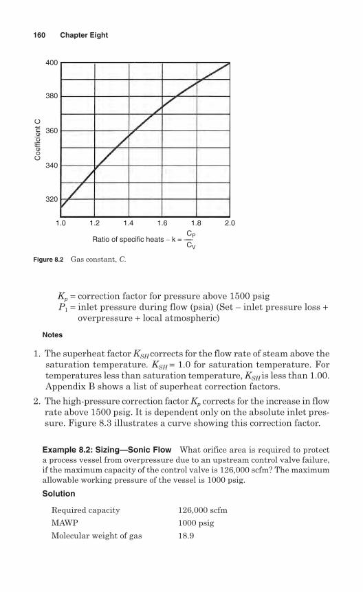
Kp = correction factor for pressure above 1500 psigP1 = inlet pressure during flow (psia) (Set – inlet pressure loss +
overpressure + local atmospheric)
Notes
1. The superheat factor KSH corrects for the flow rate of steam above thesaturation temperature. KSH = 1.0 for saturation temperature. Fortemperatures less than saturation temperature, KSH is less than 1.00.Appendix B shows a list of superheat correction factors.
2. The high-pressure correction factor Kp corrects for the increase in flowrate above 1500 psig. It is dependent only on the absolute inlet pres-sure. Figure 8.3 illustrates a curve showing this correction factor.
Example 8.2: Sizing—Sonic Flow What orifice area is required to protecta process vessel from overpressure due to an upstream control valve failure,if the maximum capacity of the control valve is 126,000 scfm? The maximumallowable working pressure of the vessel is 1000 psig.
Solution
Required capacity 126,000 scfm
MAWP 1000 psig
Molecular weight of gas 18.9
160 Chapter Eight
Figure 8.2 Gas constant, C.
400
380
360
340
320
1.0 1.2 1.4 1.6 1.8 2.0
Coe
ffici
ent C
Ratio of specific heats − k = ——CP
CV
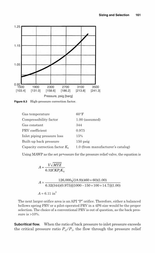
Gas temperature 60°FCompressibility factor 1.00 (assumed)
Gas constant 344
PRV coefficient 0.975
Inlet piping pressure loss 15%
Built-up back pressure 150 psig
Capacity correction factor Kb 1.0 (from manufacturer’s catalog)
Using MAWP as the set pr+essure for the pressure relief valve, the equation is
A = 6.11 in2
The next larger orifice area is an API “P” orifice. Therefore, either a balancedbellows spring PRV or a pilot-operated PRV in a 4P6 size would be the properselection. The choice of a conventional PRV is out of question, as the back pres-sure is >10%.
Subcritical flow. When the ratio of back pressure to inlet pressure exceedsthe critical pressure ratio Pcf/P1, the flow through the pressure relief
A =+
− + +126 000 18 9 460 60 1 00
6 32 344 0 975 1000 150 100 14 7 1 00
, ( . )( )( . )
. ( )( . )[( . )]( . )
AV MTZ
CKP Kb
=6 32 1.
Sizing and Selection 161
Figure 8.3 High-pressure correction factor.
1.25
1.15
1.05
0.951500
[103.4]1900
[131.0]2300
[158.6]
Pressure, psig [barg]
2700[186.2]
3100[213.8]
3500[241.3]

device is subcritical. Equations 8.4 and 8.5 may be used to calculate therequired effective discharge area for a conventional pressure relief valvethat has its spring setting adjusted to compensate for superimposedback pressure. Equations 8.4 and 8.5 may also be used for sizing a pilot-operated relief valve. The formula for calculating orifice area based onvolumetric flow rate is
(8.4)
The formula for calculating orifice area based on mass flow rate is
(8.5)
where the flow correction factor F is
Example 8.3: Sizing—Subsonic Flow What orifice area would be requiredto protect a refrigerated liquefied natural gas (LNG) storage tank from over-pressure due to vapor generated by failure of the boil-off compressor?
The calculated blow-off rate is 25,000 scfm. The MAWP of the vessel is1.50 psig.
Given
MAWP 1.5 psig
Molecular weight of gas 18.9
Gas temperature –260°FCompressibility factor (assumed) 1.0
Ratio of specific heats 1.27
Inlet piping pressure loss 0%
Discharge piping None
Solution The equation is
AV MTZ
K P FVC
=4645 1
Fk
kPP
PP
k k k
=−
−
+
12
1
2
2
1
1/ ( )/
AW TZ
K P F Mvc
=735 1
AV MTZ
K P Fvc
=4645 1
162 Chapter Eight
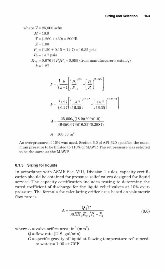
where V = 25,000 scfmM = 18.9T = (–260 + 460) = 200°RZ = 1.00
P1 = (1.50 + 0.15 + 14.7) = 16.35 psiaP2 = 14.7 psia
KVC = 0.676 @ P2/P1 = 0.899 (from manufacturer’s catalog)k = 1.27
A = 100.33 in2
An overpressure of 10% was used. Section 6.0 of API 620 specifies the maxi-mum pressure to be limited to 110% of MAWP. The set pressure was selectedto be the same as the MAWP.
8.1.5 Sizing for liquids
In accordance with ASME Sec. VIII, Division 1 rules, capacity certifi-cation should be obtained for pressure relief valves designed for liquidservice. The capacity certification includes testing to determine therated coefficient of discharge for the liquid relief valves at 10% over-pressure. The formula for calculating orifice area based on volumetricflow rate is
(8.6)
where A = valve orifice area, in2 (mm2)Q = flow rate (U.S. gal/min)G = specific gravity of liquid at flowing temperature referenced
to water = 1.00 at 70°F
AQ G
KK K P Pw v
=−38 1 2
A =25 000 18 9 200 1 0
4645 0 676 16 35 0 2984
, ( . )( )( . )
( . )( . )( . )
F =
−
1 270 27
14 716 35
14 716 35
2 1 27 2 27 1 27..
..
..
/ . . / .
Fk
k
P
P
P
P
k k k
=−
−
+
12
1
2
2
1
1/ ( )/
Sizing and Selection 163
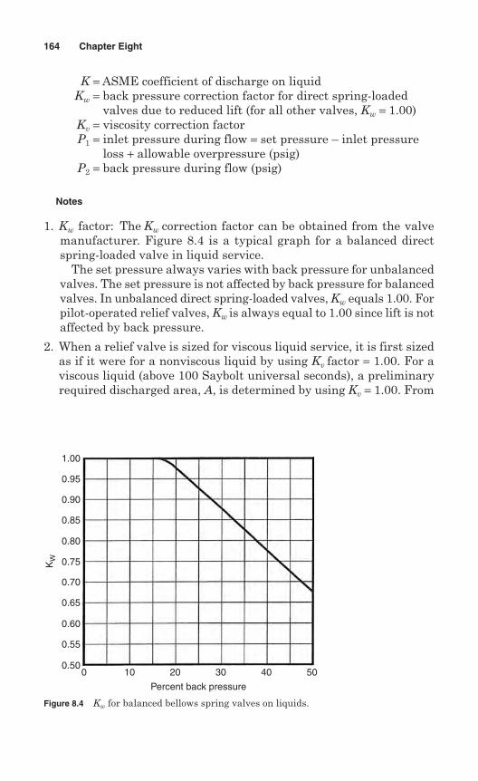
K = ASME coefficient of discharge on liquidKw = back pressure correction factor for direct spring-loaded
valves due to reduced lift (for all other valves, Kw = 1.00)Kv = viscosity correction factorP1 = inlet pressure during flow = set pressure – inlet pressure
loss + allowable overpressure (psig)P2 = back pressure during flow (psig)
Notes
1. Kw factor: The Kw correction factor can be obtained from the valvemanufacturer. Figure 8.4 is a typical graph for a balanced directspring-loaded valve in liquid service.
The set pressure always varies with back pressure for unbalancedvalves. The set pressure is not affected by back pressure for balancedvalves. In unbalanced direct spring-loaded valves, Kw equals 1.00. Forpilot-operated relief valves, Kw is always equal to 1.00 since lift is notaffected by back pressure.
2. When a relief valve is sized for viscous liquid service, it is first sizedas if it were for a nonviscous liquid by using Kv factor = 1.00. For aviscous liquid (above 100 Saybolt universal seconds), a preliminaryrequired discharged area, A, is determined by using Kv = 1.00. From
164 Chapter Eight
Figure 8.4 Kw for balanced bellows spring valves on liquids.
0 10 20
Percent back pressure
30 40 50
1.00
0.95
0.90
0.85
0.80
0.75
0.70
0.65
0.60
0.55
0.50
KW
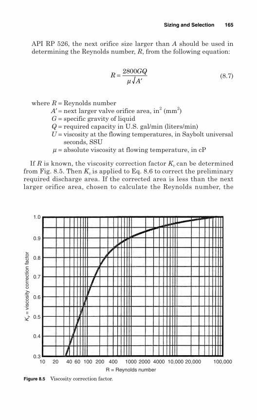
API RP 526, the next orifice size larger than A should be used indetermining the Reynolds number, R, from the following equation:
(8.7)
where R = Reynolds numberA′ = next larger valve orifice area, in2 (mm2)G = specific gravity of liquidQ = required capacity in U.S. gal/min (liters/min)U = viscosity at the flowing temperatures, in Saybolt universal
seconds, SSUm = absolute viscosity at flowing temperature, in cP
If R is known, the viscosity correction factor Kv can be determinedfrom Fig. 8.5. Then Kv is applied to Eq. 8.6 to correct the preliminaryrequired discharge area. If the corrected area is less than the nextlarger orifice area, chosen to calculate the Reynolds number, the
RGQ
A=
′2800
µ
Sizing and Selection 165
Figure 8.5 Viscosity correction factor.
1.0
0.9
0.8
0.7
Kv
= v
isco
sity
cor
rect
ion
fact
or
0.6
0.5
0.4
0.310 20 40 60 100 200 400 1000
R = Reynolds number
2000 4000 10,000 20,000 100,000
chosen orifice is adequate. If the corrected area exceeds the chosenstandard orifice area, the above calculation should be repeated usingthe next larger standard orifice size.
Example 8.4: Sizing—Liquid Flow What orifice area is required to protecta lubrication oil system from overpressure if the pump capacity is 150 gal/min?
The maximum allowable working pressure of the system is 4000 psi. Thepressure relief valve discharges into a closed header. An ASME UV valve hasbeen used.
Given
MAWP 1440 psi
Specific gravity of oil 0.75
PRV coefficient 0.74
Required flow rate 150 U.S. gal/min
Built-up back pressure 100 psig
Viscosity of oil 2000 SSU
Inlet pressure losses 3%
A full-nozzle, spring PRV is required.
Solution The required equation is
where Q = 150
G = 0.75K = 0.74
KW = 1.00P1 = 1440 – 43 + 144 = 1541 psigP2 = 100
Assume that KV = 1.00. Then
A = 0.122 in2
To correct for viscosity, the next larger orifice available for the valve type chosenis used to calculate the Reynolds number. The next larger orifice is 0.196 in2.
A =−
150 0 75
38 0 74 1 00 1 00 1541 100
.
( . )( . )( . )
AQ G
KK K P PW V
=−38 1 2
166 Chapter Eight
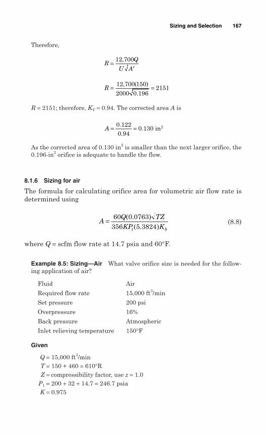
Therefore,
R = 2151; therefore, KV = 0.94. The corrected area A is
As the corrected area of 0.130 in2 is smaller than the next larger orifice, the0.196-in2 orifice is adequate to handle the flow.
8.1.6 Sizing for air
The formula for calculating orifice area for volumetric air flow rate isdetermined using
(8.8)
where Q = scfm flow rate at 14.7 psia and 60°F.
Example 8.5: Sizing—Air What valve orifice size is needed for the follow-ing application of air?
Fluid Air
Required flow rate 15,000 ft3/min
Set pressure 200 psi
Overpressure 16%
Back pressure Atmospheric
Inlet relieving temperature 150°F
Given
Q = 15,000 ft3/minT = 150 + 460 = 610°RZ = compressibility factor, use z = 1.0
P1 = 200 + 32 + 14.7 = 246.7 psiaK = 0.975
AQ TZKP Kb
= 60 0 0763356 5 38241
( . )( . )
A = =0 1220 94
0 130..
. in2
R = =12 700 150
2000 0 1962151
, ( )
.
RQ
U A=
′12 700,
Sizing and Selection 167
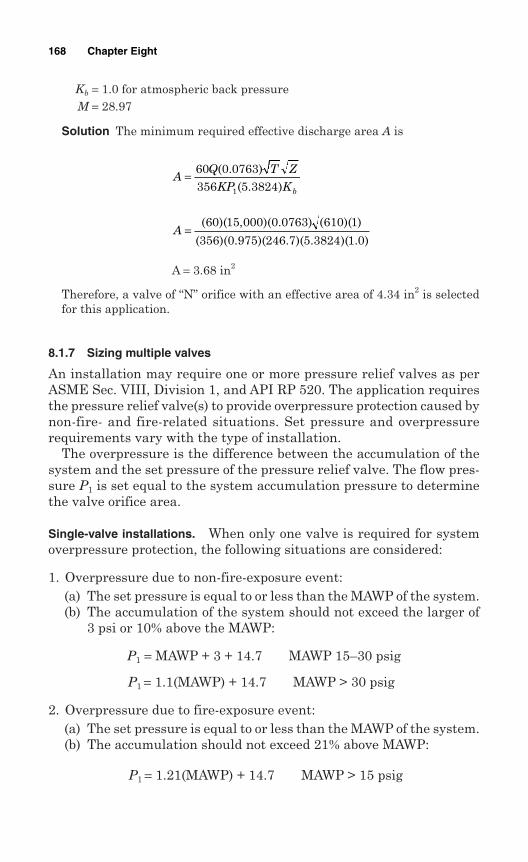
Kb = 1.0 for atmospheric back pressureM = 28.97
Solution The minimum required effective discharge area A is
A = 3.68 in2
Therefore, a valve of “N” orifice with an effective area of 4.34 in2 is selectedfor this application.
8.1.7 Sizing multiple valves
An installation may require one or more pressure relief valves as perASME Sec. VIII, Division 1, and API RP 520. The application requiresthe pressure relief valve(s) to provide overpressure protection caused bynon-fire- and fire-related situations. Set pressure and overpressurerequirements vary with the type of installation.
The overpressure is the difference between the accumulation of thesystem and the set pressure of the pressure relief valve. The flow pres-sure P1 is set equal to the system accumulation pressure to determinethe valve orifice area.
Single-valve installations. When only one valve is required for systemoverpressure protection, the following situations are considered:
1. Overpressure due to non-fire-exposure event:(a) The set pressure is equal to or less than the MAWP of the system.(b) The accumulation of the system should not exceed the larger of
3 psi or 10% above the MAWP:
P1 = MAWP + 3 + 14.7 MAWP 15–30 psig
P1 = 1.1(MAWP) + 14.7 MAWP > 30 psig
2. Overpressure due to fire-exposure event:(a) The set pressure is equal to or less than the MAWP of the system.(b) The accumulation should not exceed 21% above MAWP:
P1 = 1.21(MAWP) + 14.7 MAWP > 15 psig
A =( )( , )( . ) ( )( )
( )( . )( . )( . )( . )
60 15 000 0 0763 610 1
356 0 975 246 7 5 3824 1 0
AQ T Z
KP Kb
= 60 0 0763356 5 38241
( . )( . )
168 Chapter Eight
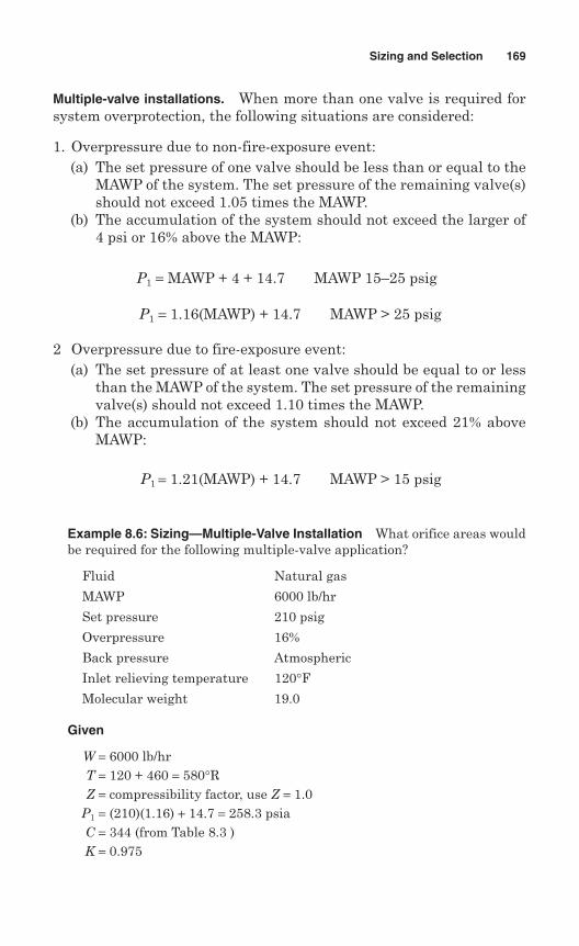
Multiple-valve installations. When more than one valve is required forsystem overprotection, the following situations are considered:
1. Overpressure due to non-fire-exposure event:(a) The set pressure of one valve should be less than or equal to the
MAWP of the system. The set pressure of the remaining valve(s)should not exceed 1.05 times the MAWP.
(b) The accumulation of the system should not exceed the larger of4 psi or 16% above the MAWP:
P1 = MAWP + 4 + 14.7 MAWP 15–25 psig
P1 = 1.16(MAWP) + 14.7 MAWP > 25 psig
2 Overpressure due to fire-exposure event:(a) The set pressure of at least one valve should be equal to or less
than the MAWP of the system. The set pressure of the remainingvalve(s) should not exceed 1.10 times the MAWP.
(b) The accumulation of the system should not exceed 21% aboveMAWP:
P1 = 1.21(MAWP) + 14.7 MAWP > 15 psig
Example 8.6: Sizing—Multiple-Valve Installation What orifice areas wouldbe required for the following multiple-valve application?
Fluid Natural gas
MAWP 6000 lb/hr
Set pressure 210 psig
Overpressure 16%
Back pressure Atmospheric
Inlet relieving temperature 120°FMolecular weight 19.0
Given
W = 6000 lb/hrT = 120 + 460 = 580°RZ = compressibility factor, use Z = 1.0
P1 = (210)(1.16) + 14.7 = 258.3 psiaC = 344 (from Table 8.3 )K = 0.975
Sizing and Selection 169
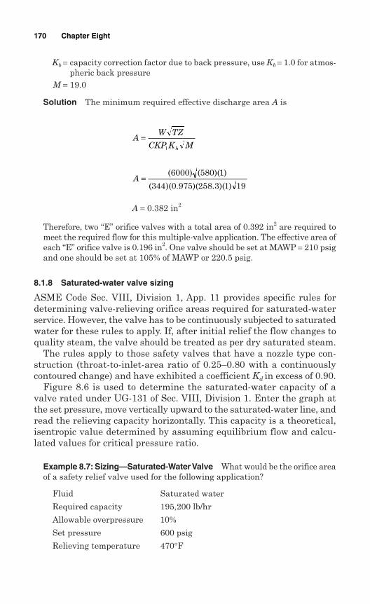
Kb = capacity correction factor due to back pressure, use Kb = 1.0 for atmos-pheric back pressure
M = 19.0
Solution The minimum required effective discharge area A is
A = 0.382 in2
Therefore, two “E” orifice valves with a total area of 0.392 in2 are required tomeet the required flow for this multiple-valve application. The effective area ofeach “E” orifice valve is 0.196 in2. One valve should be set at MAWP = 210 psigand one should be set at 105% of MAWP or 220.5 psig.
8.1.8 Saturated-water valve sizing
ASME Code Sec. VIII, Division 1, App. 11 provides specific rules fordetermining valve-relieving orifice areas required for saturated-waterservice. However, the valve has to be continuously subjected to saturatedwater for these rules to apply. If, after initial relief the flow changes toquality steam, the valve should be treated as per dry saturated steam.
The rules apply to those safety valves that have a nozzle type con-struction (throat-to-inlet-area ratio of 0.25–0.80 with a continuouslycontoured change) and have exhibited a coefficient Kd in excess of 0.90.
Figure 8.6 is used to determine the saturated-water capacity of avalve rated under UG-131 of Sec. VIII, Division 1. Enter the graph atthe set pressure, move vertically upward to the saturated-water line, andread the relieving capacity horizontally. This capacity is a theoretical,isentropic value determined by assuming equilibrium flow and calcu-lated values for critical pressure ratio.
Example 8.7: Sizing—Saturated-Water Valve What would be the orifice areaof a safety relief valve used for the following application?
Fluid Saturated water
Required capacity 195,200 lb/hr
Allowable overpressure 10%
Set pressure 600 psig
Relieving temperature 470°F
A =( ) ( )( )
( )( . )( . )( )
6000 580 1
344 0 975 258 3 1 19
AW TZ
CKP K Mb
=1
170 Chapter Eight
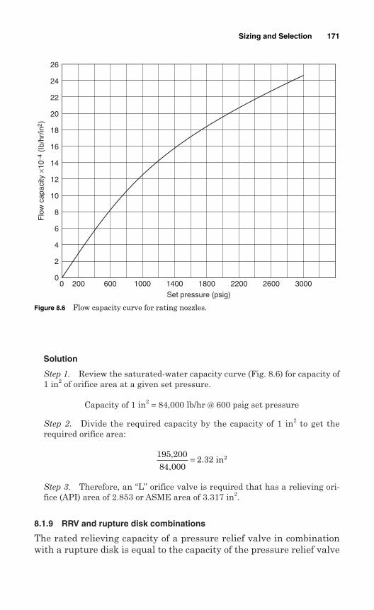
Solution
Step 1. Review the saturated-water capacity curve (Fig. 8.6) for capacity of1 in2 of orifice area at a given set pressure.
Capacity of 1 in2 = 84,000 lb/hr @ 600 psig set pressure
Step 2. Divide the required capacity by the capacity of 1 in2 to get therequired orifice area:
Step 3. Therefore, an “L” orifice valve is required that has a relieving ori-fice (API) area of 2.853 or ASME area of 3.317 in2.
8.1.9 RRV and rupture disk combinations
The rated relieving capacity of a pressure relief valve in combinationwith a rupture disk is equal to the capacity of the pressure relief valve
195 20084 000
2 32,,
.= in2
Sizing and Selection 171
Figure 8.6 Flow capacity curve for rating nozzles.
00 200 600 1000 1400 1800
Set pressure (psig)
2200 2600 3000
2
4
6
8
10
12
14
16
Flo
w c
apac
ity ×
10−4
(Ib
/hr/
in2 )
18
20
22
24
26
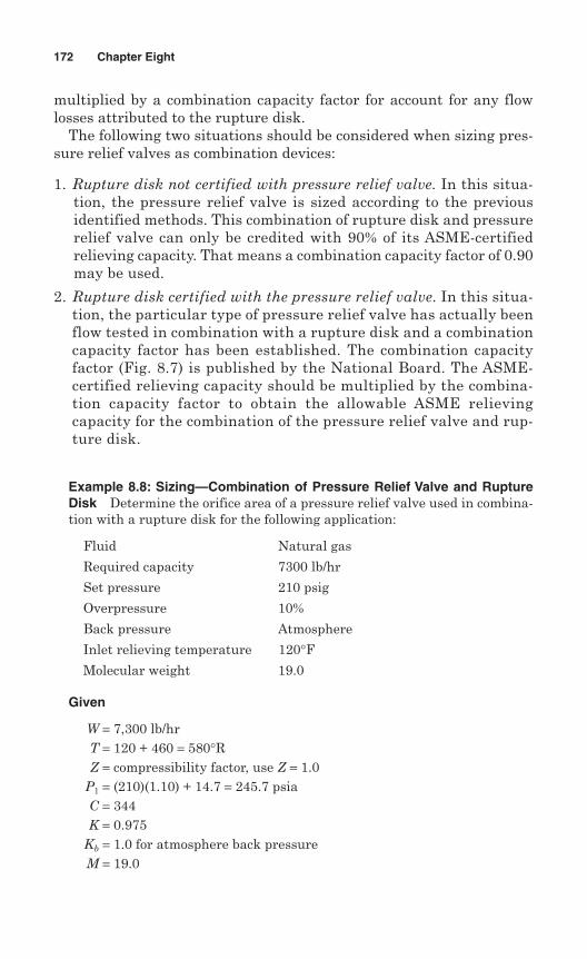
multiplied by a combination capacity factor for account for any flowlosses attributed to the rupture disk.
The following two situations should be considered when sizing pres-sure relief valves as combination devices:
1. Rupture disk not certified with pressure relief valve. In this situa-tion, the pressure relief valve is sized according to the previousidentified methods. This combination of rupture disk and pressurerelief valve can only be credited with 90% of its ASME-certifiedrelieving capacity. That means a combination capacity factor of 0.90may be used.
2. Rupture disk certified with the pressure relief valve. In this situa-tion, the particular type of pressure relief valve has actually beenflow tested in combination with a rupture disk and a combinationcapacity factor has been established. The combination capacityfactor (Fig. 8.7) is published by the National Board. The ASME-certified relieving capacity should be multiplied by the combina-tion capacity factor to obtain the allowable ASME relievingcapacity for the combination of the pressure relief valve and rup-ture disk.
Example 8.8: Sizing—Combination of Pressure Relief Valve and RuptureDisk Determine the orifice area of a pressure relief valve used in combina-tion with a rupture disk for the following application:
Fluid Natural gas
Required capacity 7300 lb/hr
Set pressure 210 psig
Overpressure 10%
Back pressure Atmosphere
Inlet relieving temperature 120°FMolecular weight 19.0
Given
W = 7,300 lb/hrT = 120 + 460 = 580°RZ = compressibility factor, use Z = 1.0
P1 = (210)(1.10) + 14.7 = 245.7 psiaC = 344K = 0.975
Kb = 1.0 for atmosphere back pressureM = 19.0
172 Chapter Eight
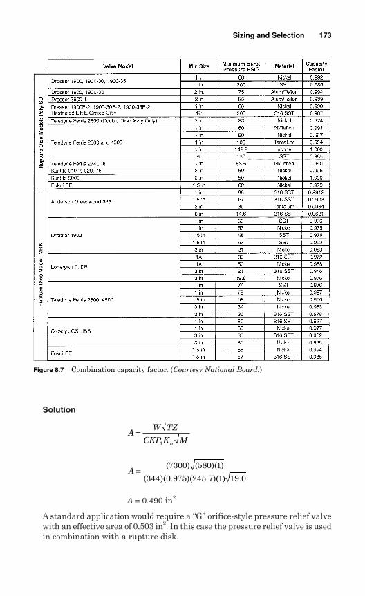
Solution
A = 0.490 in2
A standard application would require a “G” orifice-style pressure relief valvewith an effective area of 0.503 in2. In this case the pressure relief valve is usedin combination with a rupture disk.
A =( ) ( )( )
( )( . )( . )( ) .
7300 580 1
344 0 975 245 7 1 19 0
AW TZ
CKP K Mb
=1
Sizing and Selection 173
Figure 8.7 Combination capacity factor. (Courtesy National Board.)
Let us assume that a rupture disk combination factor of 0.90 would beused. The minimum required effective discharge area may be calculated usingthe following formula:
= 0.55 in2
Therefore, this application with a rupture disk would require an “H” orifice-style pressure relief valve with an effective area of 0.875 in2. This size is onevalve size larger than for pressure relief valve application alone.
8.1.10 Sizing for thermal expansionof trapped liquids
A pressure relief device should be provided where liquid-full equipmentcan be blocked in and continued heat input cannot be avoided. Flow ratesfor relieving devices to protect heat exchangers, condensers, and cool-ers against thermal expansion of trapped liquids can be determinedusing the following formula:
(8.9)
where GPM = flow rate in U.S. gal/min at the flowing temperatureB = cubical expansion coefficient per °F for the liquid at the
expected temperature differentialH = total heat transfer rate, in BTU/hr (maximum
exchanger duty during operation)G = specific gravity referred to water = 1.00 at 60°F
(compressibility of the liquid is ignored)C = specific heat in BTU/lb/°F of the trapped fluid
Notes
1. Cubical expansion coefficient B. It is recommended that this value beobtained from the process design data. Typical values of cubicalexpansion coefficient for hydrocarbon liquids and water at 60°F are:
Gravity of liquid (°API) B
3–34.9 0.0004
35–50.9 0.0005
51–63.9 0.0006
GPM = BHGC500
= 0 4900 9.
.
Required area =comb
A
F
174 Chapter Eight
64–78.9 0.0007
79–88.9 0.0008
89–93.9 0.00085
94–100 and higher 0.0009
Water 0.0001
2. Specific heat C. Typical values of specific heats at 100°F for trappedliquids are:
Liquid C
Water 4.18
Ammonia 2.18
Methane 2.27
Propane 1.75
Example 8.9: Sizing for Thermal Expansion A horizontal heat exchangervessel handles ammonia at 60°F. What is the flow rate of ammonia in gal/min?
Given
B = thermal cubical expansion 0.0006
C = specific heat of trapped fluid 2.27 Btu/lb/°FG = specific gravity 0.588
H = total heat transfer 12,000,000 Btu/hr
Solution Flow rate is determined by the following formula:
GPM = 10.78
Therefore, flow rate is 10.78 gal/min.
8.1.11 Sizing for mixed phases
A pressure relief device handling mixed phases (liquid and vapor) pro-duces flashing with vapor generation as the fluid moves through thedevice. The vapor generation should be taken into consideration, as itmay reduce the effective mass flow capacity of the device.
In the past, the API suggested treating each phase separately, with thetotal calculated orifice area being the total for all phases. Since then,alternative methodologies have been developed, and new methodologiesare under development to handle these complex multiphase systems.
GPM = ( . )( , , )( )( . )( . )0 0006 12 000 000
500 0 588 2 27
GPM = BH
GC500
Sizing and Selection 175
The Design Institute for Emergency Relief Systems (DIERS), spon-sored by the American Institute of Chemical Engineers (AIChE), hasbeen active in extensive research toward developing methods for deter-mining pressure relief valve orifice areas for multiphase systems. APIRP 520, Part 1, App. D, gives several new techniques for sizing PRVs inmultiphase systems. These methods, however, have not been validatedby test, and there is no recognized procedure for certifying the capacityof pressure relief valves in two-phase-flow service.
8.2 Rupture Disks
A rupture disk is a precision relief device designed to rupture at a prede-termined pressure and temperature. Rupture disks have to be selectedand sized very carefully to meet process requirements. The followingsteps can be used as a guide to selecting the proper type of rupturedisk:
1. List the following information: Maximum allowable working pressure of the vessel or system Maximum operating pressure Maximum temperature at the disk location Desired rupture disk burst pressure and temperature Back pressure or vacuum conditions, if any Medium, liquid or gas; corrosion characteristics of the medium Static, cycling, or pulsating device Code requirements: ASME, ISO, API, CEN, etc.
2. Calculate the ratio of maximum operating pressure to minimum burstpressure. Manufacturing range should be taken into consideration indetermining minimum burst pressure. The following is an example.
Example 8.10 The variables for rupture disk selection are given below. Whatis the ratio of maximum operating pressure to minimum burst pressure forthe rupture disk?
Maximum operating pressure 70 psig
MAWP 110 psig
Standard manufacturing range +10% to –5%
Solution If a burst pressure of 100 psig is requested, that allows a manu-facturing range of 95–110 psig. In this case, minimum burst pressure is 95psi. Therefore, the ratio of the maximum operating pressure to minimumburst pressure is 70/90 = 74%.
3. Select a disk type that meets the constraints of the pressure ratio cal-culated above. This ratio should be 0.9 or less. A lower pressure ratiooften permits the use of a less expensive disk type.
176 Chapter Eight
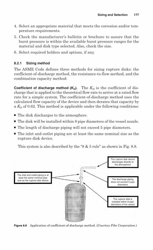
4. Select an appropriate material that meets the corrosion and/or tem-perature requirements.
5. Check the manufacturer’s bulletin or brochure to assure that theburst pressure is within the available burst pressure ranges for thematerial and disk type selected. Also, check the size.
6. Select required holders and options, if any.
8.2.1 Sizing method
The ASME Code defines three methods for sizing rupture disks: thecoefficient-of-discharge method, the resistance-to-flow method, and thecombination capacity method:
Coefficient of discharge method (KD). The KD is the coefficient of dis-charge that is applied to the theoretical flow rate to arrive at a rated flowrate for a simple system. The coefficient-of-discharge method uses thecalculated flow capacity of the device and then derates that capacity bya KD of 0.62. This method is applicable under the following conditions:
The disk discharges to the atmosphere. The disk will be installed within 8 pipe diameters of the vessel nozzle. The length of discharge piping will not exceed 5 pipe diameters. The inlet and outlet piping are at least the same nominal size as the
rupture disk device.
This system is also described by the “8 & 5 rule” as shown in Fig. 8.8.
Sizing and Selection 177
Figure 8.8 Application of coefficient-of-discharge method.
The inlet and outlet piping is atleast the same nominal pipe
size as the rupture disk device
The rupture disk devicedischarges directly to
the atmosphere
The discharge pipingdoes not exceed 5 pipe
diameters
The rupture disk isinstalled within 8 pipe
diameters of the vessel
Figure 8.8 Application of coefficient-of-discharge method. (Courtesy Fike Corporation.)
Resistance-to-flow method (KR). The rupture disk is considered as a flow-resistive element within the relief system. The resistance of the rupturedisk is denoted by the certified resistance factor KR. The KR value rep-resents the velocity head loss due to the rupture disk device. This headloss is included in the overall system loss calculations to determine thecapacity of the relief system. It is also important to note that the certi-fied KR represents the device (disk and disk holder), not just the rup-ture disk. If there is no holder, the KR value is for the disk.
The resistance-to-flow method requires that the calculated relievingcapacity of the system be multiplied by 0.90 to allow for uncertaintiesinherent in this method. This method is applicable under the followingconditions:
When the 8 & 5 rule does not apply For calculating the pressure drop between the pressure vessel and the
valve, when the disk is installed in combination with a pressure reliefvalve
Combination capacity method. The combination capacity method is usedwhen a rupture disk is installed on the inlet side of a pressure relief valve.This method requires that a rupture disk of the same nominal size orlarger than the pressure relief valve’s inlet be used, and one then der-ates the valve capacity by 0.90 or higher for that disk/valve combination.
178 Chapter Eight
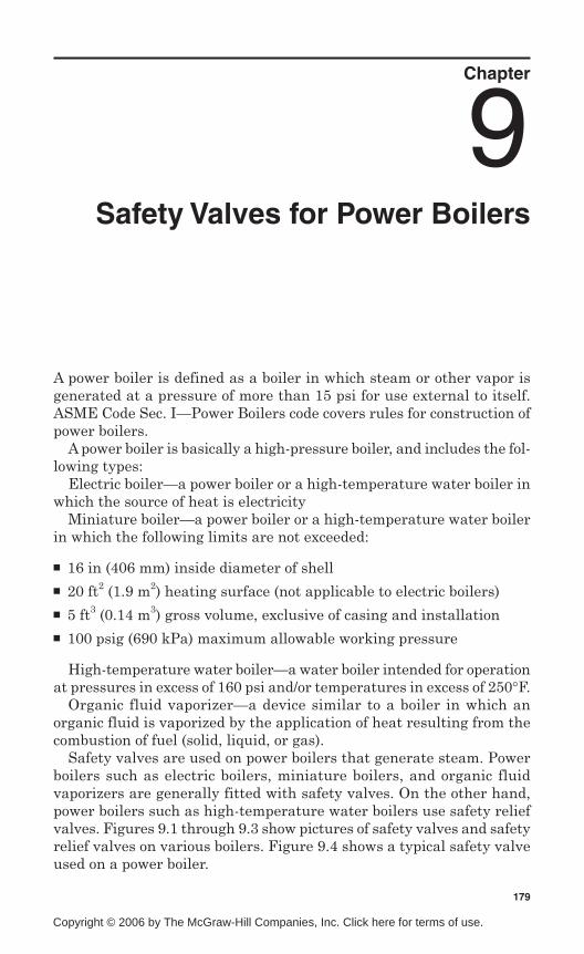
Chapter
9Safety Valves for Power Boilers
A power boiler is defined as a boiler in which steam or other vapor isgenerated at a pressure of more than 15 psi for use external to itself.ASME Code Sec. I—Power Boilers code covers rules for construction ofpower boilers.
A power boiler is basically a high-pressure boiler, and includes the fol-lowing types:
Electric boiler—a power boiler or a high-temperature water boiler inwhich the source of heat is electricity
Miniature boiler—a power boiler or a high-temperature water boilerin which the following limits are not exceeded:
16 in (406 mm) inside diameter of shell 20 ft2 (1.9 m2) heating surface (not applicable to electric boilers) 5 ft3 (0.14 m3) gross volume, exclusive of casing and installation 100 psig (690 kPa) maximum allowable working pressure
High-temperature water boiler—a water boiler intended for operationat pressures in excess of 160 psi and/or temperatures in excess of 250°F.
Organic fluid vaporizer—a device similar to a boiler in which anorganic fluid is vaporized by the application of heat resulting from thecombustion of fuel (solid, liquid, or gas).
Safety valves are used on power boilers that generate steam. Powerboilers such as electric boilers, miniature boilers, and organic fluidvaporizers are generally fitted with safety valves. On the other hand,power boilers such as high-temperature water boilers use safety reliefvalves. Figures 9.1 through 9.3 show pictures of safety valves and safetyrelief valves on various boilers. Figure 9.4 shows a typical safety valveused on a power boiler.
179
Copyright © 2006 by The McGraw-Hill Companies, Inc. Click here for terms of use.
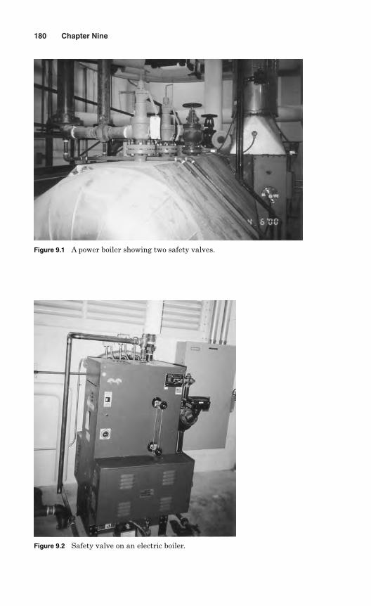
180 Chapter Nine
Figure 9.1 A power boiler showing two safety valves.
Figure 9.2 Safety valve on an electric boiler.
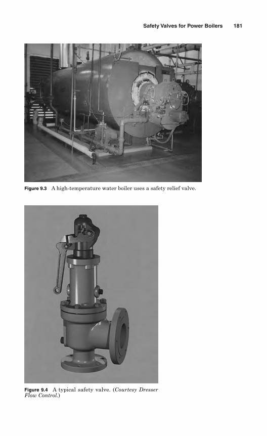
Safety Valves for Power Boilers 181
Figure 9.3 A high-temperature water boiler uses a safety relief valve.
Figure 9.4 A typical safety valve. (Courtesy DresserFlow Control.)
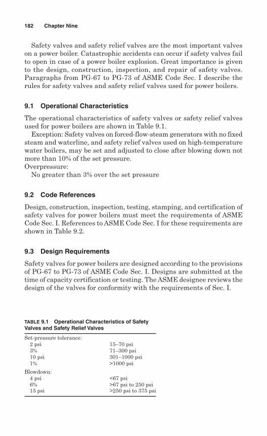
Safety valves and safety relief valves are the most important valveson a power boiler. Catastrophic accidents can occur if safety valves failto open in case of a power boiler explosion. Great importance is givento the design, construction, inspection, and repair of safety valves.Paragraphs from PG-67 to PG-73 of ASME Code Sec. I describe therules for safety valves and safety relief valves used for power boilers.
9.1 Operational Characteristics
The operational characteristics of safety valves or safety relief valvesused for power boilers are shown in Table 9.1.
Exception: Safety valves on forced-flow-steam generators with no fixedsteam and waterline, and safety relief valves used on high-temperaturewater boilers, may be set and adjusted to close after blowing down notmore than 10% of the set pressure.Overpressure:
No greater than 3% over the set pressure
9.2 Code References
Design, construction, inspection, testing, stamping, and certification ofsafety valves for power boilers must meet the requirements of ASMECode Sec. I. References to ASME Code Sec. I for these requirements areshown in Table 9.2.
9.3 Design Requirements
Safety valves for power boilers are designed according to the provisionsof PG-67 to PG-73 of ASME Code Sec. I. Designs are submitted at thetime of capacity certification or testing. The ASME designee reviews thedesign of the valves for conformity with the requirements of Sec. I.
182 Chapter Nine
TABLE 9.1 Operational Characteristics of SafetyValves and Safety Relief Valves
Set-pressure tolerance:2 psi 15–70 psi3% 71–300 psi10 psi 301–1000 psi1% >1000 psi
Blowdown:4 psi <67 psi6% >67 psi to 250 psi15 psi >250 psi to 375 psi
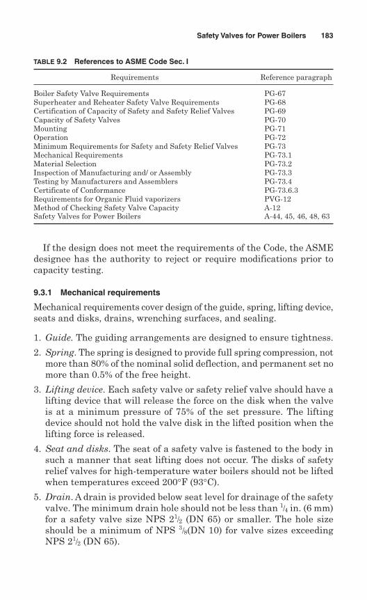
If the design does not meet the requirements of the Code, the ASMEdesignee has the authority to reject or require modifications prior tocapacity testing.
9.3.1 Mechanical requirements
Mechanical requirements cover design of the guide, spring, lifting device,seats and disks, drains, wrenching surfaces, and sealing.
1. Guide. The guiding arrangements are designed to ensure tightness.
2. Spring. The spring is designed to provide full spring compression, notmore than 80% of the nominal solid deflection, and permanent set nomore than 0.5% of the free height.
3. Lifting device. Each safety valve or safety relief valve should have alifting device that will release the force on the disk when the valveis at a minimum pressure of 75% of the set pressure. The liftingdevice should not hold the valve disk in the lifted position when thelifting force is released.
4. Seat and disks. The seat of a safety valve is fastened to the body insuch a manner that seat lifting does not occur. The disks of safetyrelief valves for high-temperature water boilers should not be liftedwhen temperatures exceed 200°F (93°C).
5. Drain. A drain is provided below seat level for drainage of the safetyvalve. The minimum drain hole should not be less than 1/4 in. (6 mm)for a safety valve size NPS 21/2 (DN 65) or smaller. The hole sizeshould be a minimum of NPS 3/8(DN 10) for valve sizes exceedingNPS 21/2 (DN 65).
Safety Valves for Power Boilers 183
TABLE 9.2 References to ASME Code Sec. I
Requirements Reference paragraph
Boiler Safety Valve Requirements PG-67Superheater and Reheater Safety Valve Requirements PG-68Certification of Capacity of Safety and Safety Relief Valves PG-69Capacity of Safety Valves PG-70Mounting PG-71Operation PG-72Minimum Requirements for Safety and Safety Relief Valves PG-73Mechanical Requirements PG-73.1Material Selection PG-73.2Inspection of Manufacturing and/ or Assembly PG-73.3Testing by Manufacturers and Assemblers PG-73.4Certificate of Conformance PG-73.6.3Requirements for Organic Fluid vaporizers PVG-12Method of Checking Safety Valve Capacity A-12Safety Valves for Power Boilers A-44, 45, 46, 48, 63
6. Wrenching surfaces. Provisions are made for wrenching surfaces forscrewed inlet and outlet connections.
7. Sealing. Means should be provided for sealing the valves after adjust-ments.
8. Body. The valve body should be designed to minimize the effects ofwater deposits.
9.3.2 Material selection
Materials as permitted by ASME Code Sec. I are used for constructionof safety and safety relief valves for power boiler service. Materials usedfor bodies and bonnets or yokes are required to be listed in ASME CodeSec. II, Parts A, B, and identified in Tables 1A and 1B of Sec. II, Part D.
Materials for nozzles, disks, and other parts must be from one of thefollowing categories:
1. Listed in Sec. II
2. Listed in ASTM Specifications
3. Controlled by the manufacturer to ensure that chemical and physi-cal properties are at least equivalent to ASTM Standards.
In the latter case, the manufacturer is responsible for ensuring thatthe allowable stresses at temperature meet the requirements of Sec. II,Part D, App. I—Nonmandatory Basis for Establishing Stress Values inTables 1A and 1B.
Cast iron seats and disks are not permitted to be used for safetyvalves and safety relief valves for power boiler service. It is required thatcorrosion-resistant materials be used for seats, guides, disks, disk hold-ers, and springs.
9.3.3 Boiler safety valves
Each power boiler is required to have at least one safety valve or safetyrelief valve. Two or more safety valves are required if the bare-tubewater-heating surface is more than 500 ft2 (47 m2). Two or more safetyvalves are also required if the combined bare-tube and extended water-heating surface is more than 500 ft2 (47 m2) , and steam-generatingcapacity of the boiler is more than 4000 lb/hr (1800 kg/h ). The totalvalve capacity for each boiler should be able to discharge all the steamgenerated by the boiler without permitting the pressure to rise morethan 6% above the highest safety valve setting, but in no case morethan 6% above the maximum allowable working pressure (MAWP) asshown in Fig. 9.5.
184 Chapter Nine
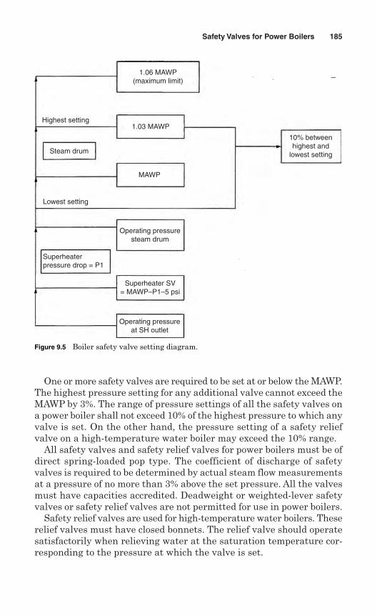
One or more safety valves are required to be set at or below the MAWP.The highest pressure setting for any additional valve cannot exceed theMAWP by 3%. The range of pressure settings of all the safety valves ona power boiler shall not exceed 10% of the highest pressure to which anyvalve is set. On the other hand, the pressure setting of a safety reliefvalve on a high-temperature water boiler may exceed the 10% range.
All safety valves and safety relief valves for power boilers must be ofdirect spring-loaded pop type. The coefficient of discharge of safetyvalves is required to be determined by actual steam flow measurementsat a pressure of no more than 3% above the set pressure. All the valvesmust have capacities accredited. Deadweight or weighted-lever safetyvalves or safety relief valves are not permitted for use in power boilers.
Safety relief valves are used for high-temperature water boilers. Theserelief valves must have closed bonnets. The relief valve should operatesatisfactorily when relieving water at the saturation temperature cor-responding to the pressure at which the valve is set.
Safety Valves for Power Boilers 185
1.06 MAWP(maximum limit)
1.03 MAWP
Steam drum
Highest setting
Lowest setting
Superheaterpressure drop = P1
Operating pressureat SH outlet
Superheater SV= MAWP–P1–5 psi
Operating pressuresteam drum
MAWP
10% betweenhighest and
lowest setting
Figure 9.5 Boiler safety valve setting diagram.
A safety valve or safety relief valve over NPS 3 (DN 80), if used for apower boiler operating at more than 15 psig, must have a flanged inletconnection or a weld-end inlet connection. The dimension of flanges isrequired to confirm the applicable ASME Standards.
For forced-flow steam generators with no fixed steam and waterline(Fig. 9.6), equipped with automatic controls and interlocks responsiveto steam pressure, safety valves must be provided in accordance withpar. PG-67.4 of Sec. I. One or more power-actuated pressure reliefvalves must be provided in direct communication with the boiler whenthe boiler is under pressure and receive a control impulse to open whenthe MAWP at the superheater outlet is exceeded. The total relievingcapacity should not be less than 10% of the maximum design steamingcapacity of the boiler under any operating conditions. The valve(s) maybe located anywhere in the pressure part system where they can relieveoverpressure.
Spring-loaded safety valves may be provided, with total relievingcapacity, including that of power-actuated pressure-relieving capacityif installed, of not less than 100% of the maximum designed steamingcapacity of the boiler. In this case, relieving capacity of not more than30% should be allowed for the power-actuated pressure relief valvesactually installed. Any or all the spring-loaded safety valves may be setabove MAWP. The set pressures should be such that all the valves inoperation, together with power-actuated pressure relief valves, shouldnot raise the operating pressure more than 20% above the MAWP of anypart of the boiler.
9.3.4 Superheater safety valves
Each attached superheater is required to be equipped with one or moresafety valves. The valve(s) should be located in the steam flow pathbetween the superheater outlet and the first stop valve. The valve(s) mayalso be located anywhere in the length of the header. The dischargecapacity of the safety valve on a superheater may be included in deter-mining the number and size of the safety valves for the boiler if thereis no valve between the superheater safety valve and the boiler. In thatcase, the boiler safety valves must release 75% of the total valve capac-ity required.
Each superheater, if separately fired and can be separated from theboiler by shutoff, is required to be equipped with one or more safetyvalves with a total capacity equal to 6 lb of steam per square foot ofsuperheater surface. Alternatively, the manufacturer may calculate theminimum safety valve relieving capacity in lb/hr from the maximumexpected heat absorption in Btu/hr, divided by 1000.
186 Chapter Nine
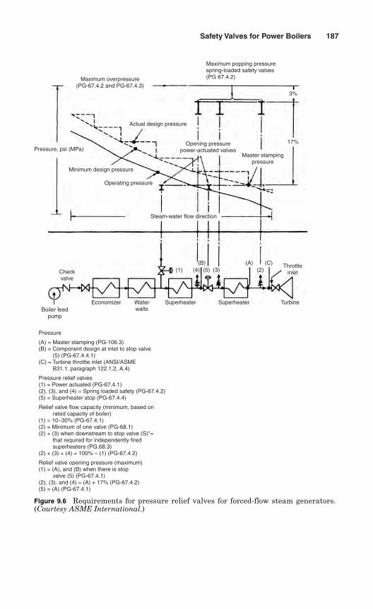
Safety Valves for Power Boilers 187
Pressure
(A) = Master stamping (PG-106.3)(B) = Component design at inlet to stop valve (5) (PG-67.4.4.1)(C) = Turbine throttle inlet (ANSI/ASME B31.1. paragraph 122.1.2, A.4)
Pressure relief valves(1) = Power actuated (PG-67.4.1)(2), (3), and (4) = Spring loaded safety (PG-67.4.2)(5) = Superheater stop (PG-67.4.4)
Relief valve flow capacity (minimum, based on rated capacity of boiler)(1) = 10–30% (PG-67.4.1)(2) = Minimum of one valve (PG-68.1)(2) + (3) when downstream to stop valve (S)"= that required for independently fired superheaters (PG.68.3)(2) + (3) + (4) = 100% – (1) (PG-67.4.2)
Relief valve opening pressure (maximum)(1) = (A), and (B) when there is stop valve (5) (PG-67.4.1)(2), (3), and (4) = (A) + 17% (PG-67.4.2)(5) = (A) (PG-67.4.1)
Maximum overpressure(PG-67.4.2 and PG-67.4.3)
Maximum popping pressurespring-loaded safety valves(PG 67.4.2)
Actual design pressure
Pressure, psi (MPa)
Minimum design pressure
Operating pressure
Steam-water flow direction
Opening pressurepower-actuated valves
Master stampingpressure
17%
3%
Checkvalve
Boiler feedpump
Economizer Waterwalts
Superheater Superheater Turbine
(1) (4) (5)(B) (A) (C)
(3) (2)Throttle
inlet
Figure 9.6 Requirements for pressure relief valves for forced-flow steam generators.(Courtesy ASME International.)
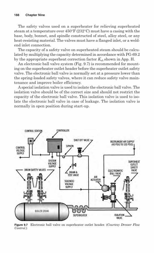
The safety valves used on a superheater for relieving superheatedsteam at a temperature over 450°F (232°C) must have a casing with thebase, body, bonnet, and spindle constructed of steel, alloy steel, or anyheat-resisting material. The valves must have a flanged inlet, or a weld-end inlet connection.
The capacity of a safety valve on superheated steam should be calcu-lated by multiplying the capacity determined in accordance with PG-69.2by the appropriate superheat correction factor Ksh shown in App. H.
An electronic ball valve system (Fig. 9.7) is recommended for mount-ing on the superheater outlet header before the superheater outlet safetyvalve. The electronic ball valve is normally set at a pressure lower thanthe spring-loaded safety valves, where it can reduce safety valve main-tenance and improve boiler efficiency.
A special isolation valve is used to isolate the electronic ball valve. Theisolation valve should be of the correct size and should not restrict thecapacity of the electronic ball valve. This isolation valve is used to iso-late the electronic ball valve in case of leakage. The isolation valve isnormally in open position during start-up.
188 Chapter Nine
Figure 9.7 Electronic ball valve on superheater outlet header. (Courtesy Dresser FlowControl.)
9.3.5 Reheater safety valves
Each reheater is required to have one or more safety valves, the totalcapacity of which is at least equal to the maximum steam flow capacityof the heater. The discharge capacity of the reheater safety valves mustnot be included in determining the safety valve requirements for theboiler. One or more safety valves with a combined capacity of at least15% of the total capacity should be located in the steam flow pathbetween the reheater outlet and the first stop valve.
The safety valves used on a reheater for relieving superheated steamat a temperature over 450°F (232°C) must have a casing with the base,body, bonnet, and spindle constructed of steel, alloy steel, or any heat-resisting material. The valves must have a flanged inlet, or a weld-endinlet connection.
9.3.6 Organic fluid vaporizer safety valves
An organic fluid vaporizer is considered a power boiler in which anorganic fluid is vaporized by the application of heat resulting from thecombustion of fuels (solid, liquid, or gaseous). An organic fluid vaporizeris constructed in accordance with the rules of Part PVG of ASME CodeSec. I—Power Boilers.
Specially designed safety valves are used on organic fluid vaporizersas the discharge of the safety valves are conducted back through a con-denser to the storage system.
Safety valves should be of a totally enclosed type designed so thatvapors escaping beyond the valve seat will not be discharged into theatmosphere. The safety valve should not have a lifting lever.
Safety valves are normally disconnected from the vaporizer annu-ally. The valves should be inspected, repaired if necessary, tested, andinstalled back on the vaporizer. It should be noted that a qualified safetyvalve repair shop should repair the safety valves.
The safety valves for organic fluid vaporizers should be tested and cer-tified in accordance with Par. PG-69 of Sec. I. The valves should bestamped with the rated relieving capacity in lb/hr and the fluid identi-fication, in addition to the symbol stamp V.
9.4 Capacity Requirements
The minimum required relieving capacity of a power boiler must be atleast equal to the maximum designed steam generation capacity of theboiler. The manufacturer is required to certify the maximum designedsteaming capacity in lb/hr of a power boiler.
The manufacturer determines the minimum required relieving capac-ity of a waste heat boiler. If auxiliary firing is used, the manufacturer
Safety Valves for Power Boilers 189
is required to include the effect of such firing in the total output maxi-mum output capacity.
For a high-temperature water boiler, the minimum required capac-ity is obtained by dividing the maximum output at the boiler nozzle, pro-duced by the highest heating value of fuel for which the boiler isdesigned, by 1000.
Each economizer, if it can be isolated from the boiler by a shut-off valve,is required to have one or more safety relief valves with a total dischargecapacity in lb/hr, divided by 1000. This discharge capacity is determinedby the manufacturer from the heat absorption capacity in Btu/hr, and theabsorption capacity is required to be stated on the stamping.
9.4.1 Relieving capacity
Asafety valve or safety relieve valve should have sufficient capacity to dis-charge all the steam that is generated by the boiler. The minimum reliev-ing capacity of a power boiler can be determined by either of two methods:
1. By measuring the maximum amount of fuel that can be burned
2. By estimating the pounds of steam generated based on heating surface
Capacity based on fuel burning. The maximum quantity of fuel, C, whichcan be burned at the time of maximum forcing is determined by a test.The following formula is used to calculate the required minimum reliev-ing capacity of a safety valve based on the maximum amount of fuelburned:
where W = steam generated, lb/hrC = total weight or volume of fuel burned at the time of
maximum forcing, lb or ft3
H = heat of combustion of fuel, Btu/lb or Btu/ft3
Total capacity is the summation of capacity of each safety valve, whichshould be equal to or greater than W.
Capacity based on heating surface. The heating surface of a boiler isdefined as the area that is exposed to the heating medium for absorp-tion and transfer of heat to the heat medium. It is the area expressedin ft2, and is calculated for the surface receiving the heat. A boiler designis basically a layout of heating surfaces to obtain maximum efficiencyand capacity.
WC H= × × 0 75
1100.
190 Chapter Nine
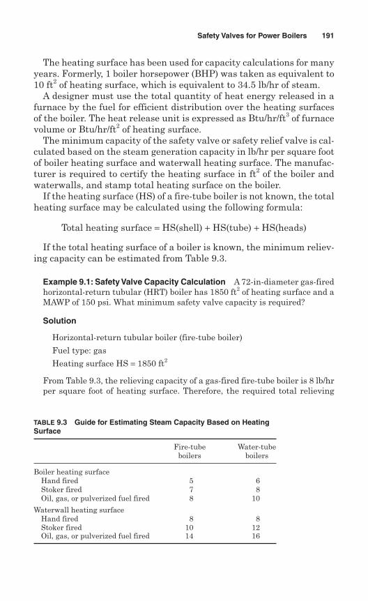
The heating surface has been used for capacity calculations for manyyears. Formerly, 1 boiler horsepower (BHP) was taken as equivalent to10 ft2 of heating surface, which is equivalent to 34.5 lb/hr of steam.
A designer must use the total quantity of heat energy released in afurnace by the fuel for efficient distribution over the heating surfacesof the boiler. The heat release unit is expressed as Btu/hr/ft3 of furnacevolume or Btu/hr/ft2 of heating surface.
The minimum capacity of the safety valve or safety relief valve is cal-culated based on the steam generation capacity in lb/hr per square footof boiler heating surface and waterwall heating surface. The manufac-turer is required to certify the heating surface in ft2 of the boiler andwaterwalls, and stamp total heating surface on the boiler.
If the heating surface (HS) of a fire-tube boiler is not known, the totalheating surface may be calculated using the following formula:
Total heating surface = HS(shell) + HS(tube) + HS(heads)
If the total heating surface of a boiler is known, the minimum reliev-ing capacity can be estimated from Table 9.3.
Example 9.1: Safety Valve Capacity Calculation A 72-in-diameter gas-firedhorizontal-return tubular (HRT) boiler has 1850 ft2 of heating surface and aMAWP of 150 psi. What minimum safety valve capacity is required?
Solution
Horizontal-return tubular boiler (fire-tube boiler)
Fuel type: gas
Heating surface HS = 1850 ft2
From Table 9.3, the relieving capacity of a gas-fired fire-tube boiler is 8 lb/hrper square foot of heating surface. Therefore, the required total relieving
Safety Valves for Power Boilers 191
TABLE 9.3 Guide for Estimating Steam Capacity Based on HeatingSurface
Fire-tube Water-tubeboilers boilers
Boiler heating surfaceHand fired 5 6Stoker fired 7 8Oil, gas, or pulverized fuel fired 8 10
Waterwall heating surfaceHand fired 8 8Stoker fired 10 12Oil, gas, or pulverized fuel fired 14 16
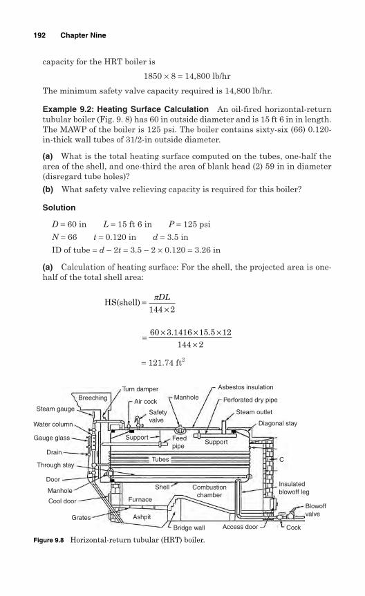
capacity for the HRT boiler is
1850 × 8 = 14,800 lb/hr
The minimum safety valve capacity required is 14,800 lb/hr.
Example 9.2: Heating Surface Calculation An oil-fired horizontal-returntubular boiler (Fig. 9. 8) has 60 in outside diameter and is 15 ft 6 in in length.The MAWP of the boiler is 125 psi. The boiler contains sixty-six (66) 0.120-in-thick wall tubes of 31/2-in outside diameter.
(a) What is the total heating surface computed on the tubes, one-half thearea of the shell, and one-third the area of blank head (2) 59 in in diameter(disregard tube holes)?
(b) What safety valve relieving capacity is required for this boiler?
Solution
D = 60 in L = 15 ft 6 in P = 125 psi
N = 66 t = 0.120 in d = 3.5 in
ID of tube = d – 2t = 3.5 – 2 × 0.120 = 3.26 in
(a) Calculation of heating surface: For the shell, the projected area is one-half of the total shell area:
= 121.74 ft2
= × × ××
60 3 1416 15 5 12144 2
. .
HS(shell) =×
πDL
144 2
192 Chapter Nine
Breeching
Steam gauge
Water column
Gauge glass
Drain
Through stay
Door
Manhole
Cool door
Grates Ashpit
Furnace
Shell
Tubes
Bridge wall Cock
Blowoffvalve
Insulatedblowoff leg
C
Diagonal stay
Steam outlet
Perforated dry pipe
Asbestos insulation
Manhole
Safetyvalve
Turn damper
Air cock
Support Feedpipe
Support
Combustionchamber
Access door
Figure 9.8 Horizontal-return tubular (HRT) boiler.
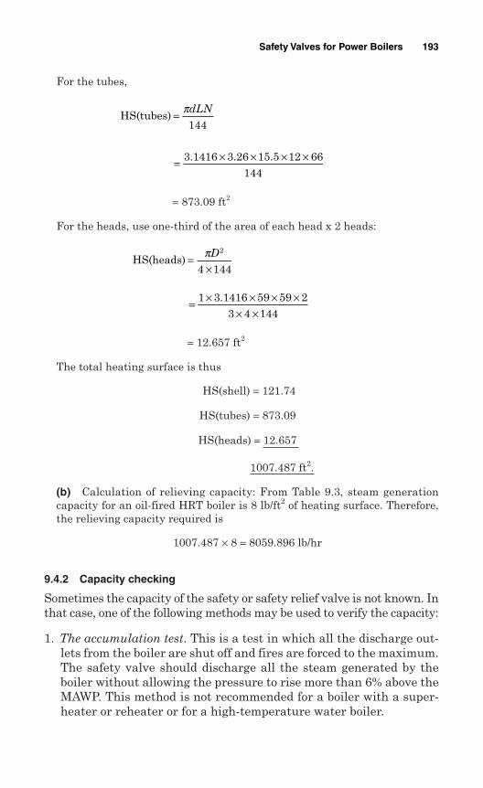
For the tubes,
= 873.09 ft2
For the heads, use one-third of the area of each head x 2 heads:
= 12.657 ft2
The total heating surface is thus
HS(shell) = 121.74
HS(tubes) = 873.09
HS(heads) = 12.657
1007.487 ft2.
(b) Calculation of relieving capacity: From Table 9.3, steam generationcapacity for an oil-fired HRT boiler is 8 lb/ft2 of heating surface. Therefore,the relieving capacity required is
1007.487 × 8 = 8059.896 lb/hr
9.4.2 Capacity checking
Sometimes the capacity of the safety or safety relief valve is not known. Inthat case, one of the following methods may be used to verify the capacity:
1. The accumulation test. This is a test in which all the discharge out-lets from the boiler are shut off and fires are forced to the maximum.The safety valve should discharge all the steam generated by theboiler without allowing the pressure to rise more than 6% above theMAWP. This method is not recommended for a boiler with a super-heater or reheater or for a high-temperature water boiler.
= × × × ×× ×
1 3 1416 59 59 23 4 144
.
HS(heads) =×πD2
4 144
= × × × ×3 1416 3 26 15 5 12 66144
. . .
HS(tubes) = πdLN
144
Safety Valves for Power Boilers 193
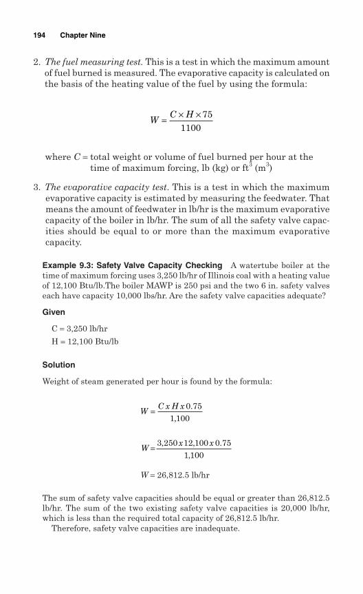
2. The fuel measuring test. This is a test in which the maximum amountof fuel burned is measured. The evaporative capacity is calculated onthe basis of the heating value of the fuel by using the formula:
where C = total weight or volume of fuel burned per hour at thetime of maximum forcing, lb (kg) or ft3 (m3)
3. The evaporative capacity test. This is a test in which the maximumevaporative capacity is estimated by measuring the feedwater. Thatmeans the amount of feedwater in lb/hr is the maximum evaporativecapacity of the boiler in lb/hr. The sum of all the safety valve capac-ities should be equal to or more than the maximum evaporativecapacity.
Example 9.3: Safety Valve Capacity Checking A watertube boiler at thetime of maximum forcing uses 3,250 lb/hr of Illinois coal with a heating valueof 12,100 Btu/lb.The boiler MAWP is 250 psi and the two 6 in. safety valveseach have capacity 10,000 lbs/hr. Are the safety valve capacities adequate?
Given
C = 3,250 lb/hr
H = 12,100 Btu/lb
Solution
Weight of steam generated per hour is found by the formula:
W = 26,812.5 lb/hr
The sum of safety valve capacities should be equal or greater than 26,812.5lb/hr. The sum of the two existing safety valve capacities is 20,000 lb/hr,which is less than the required total capacity of 26,812.5 lb/hr.
Therefore, safety valve capacities are inadequate.
Wx x= 3 250 12 100 0 75
1 100, , .
,
WC x H x= 0 75
1 100.
,
WC H= × × 75
1100
194 Chapter Nine
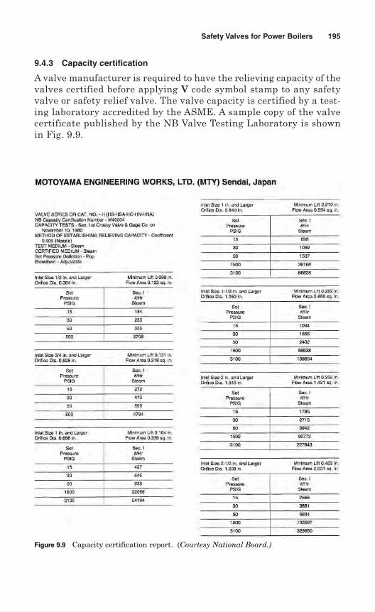
9.4.3 Capacity certification
A valve manufacturer is required to have the relieving capacity of thevalves certified before applying V code symbol stamp to any safetyvalve or safety relief valve. The valve capacity is certified by a test-ing laboratory accredited by the ASME. A sample copy of the valvecertificate published by the NB Valve Testing Laboratory is shownin Fig. 9.9.
Safety Valves for Power Boilers 195
Figure 9.9 Capacity certification report. (Courtesy National Board.)
The rules for ASME acceptance of testing laboratories and AuthorizedObservers for conducting capacity certification tests of safety and safetyrelief valves are given in App. A-310 of Sec. I of the ASME Code. AnAuthorized Observer is an ASME-designated person who supervisescapacity certification tests only at testing facilities specified by theASME. An ASME designee reviews and evaluates the experience of per-sons interested in becoming Authorized Observers, and makes recom-mendations to the Society.
The manufacturer and the Authorized Observers sign the capacity testdata reports after completion of tests on each valve design and size. Thecapacity test reports, with drawings for valve construction, are sub-mitted to the ASME designee for review and acceptance.
Capacity certification tests are conducted at a pressure not exceedingset pressure by 3% or 2 psi (7 kPa), whichever is greater. The valves areadjusted so that blowdown does not exceed 4% of the set pressure. Thetests are conducted by using dry saturated steam of 98% minimumquality and 20°F (11°C) maximum superheat.
New tests are performed if changes are made in the design of the valvethat affect the flow path, lift, or performance characteristics of the valve.
Three methods, (1) the three-valve method, (2) the slope method, and(3) the coefficient-of-discharge method, are permitted for capacity cer-tification. Relieving capacity of a safety valve or safety relief valve maybe determined using one of the methods.
Three-valve method. In the three-valve method, a set of three valves foreach combination of size, design, and pressure setting is tested. On test,the capacity should stay within the range of ±5% of the average capac-ity. If the test fails for one valve, it is required to be replaced with twovalves. Now a new average capacity of four valves is calculated, andtested again. If the test result for a valve fails to fall within ±5% of thenew average, that valve design is rejected.
The rated relieving capacity for each combination of design, size, andtest pressure is required to be 90% of the average capacity.
Slope method. In the slope method, a set of four valves for each combi-nation of pipe size and orifice size is tested. The valves are set at pres-sures covering the range of pressures for which the valves will be usedor the range of pressures available at the testing laboratory. The capac-ities are determined as follows.
The slope W/P of the measured capacity versus the flow pressure foreach test is calculated on average:
Slopemeasured capacity, lb/hr
absolute flow rating pressure, psia= =W
P
196 Chapter Nine
The values obtained from testing are required to stay within ±5% ofthe average value:
Minimum slope = 0.95 × average slope
Maximum slope = 1.05 × average slope
The Authorized Observer is required to witness testing of additionalvalves at the rate of two for each valve if the values from the testing donot fall within the above minimum and maximum slope values.
When rated, relieving capacity must not exceed 90% of the averageslope times the absolute accumulation pressure:
Rated slope = 0.90 × average slope
The stamped capacity ≤ rated slope (1.03 × set pressure + 14.7) or (setpressure + 2 psi + 14.7), whichever is greater.
Coefficient-of-discharge method. In the coefficient-of-discharge method,a coefficient of discharge, K, is established for a specific valve design.The manufacturer is required to submit at least three valves for eachof three different sizes, a total of nine valves, for testing. Each valve isset at a different pressure covering the range of pressures for which thevalves will be used or the range of pressures available at the test labo-ratory. The test is performed on each valve to determine its lift, popping,and blowdown pressures, and actual relieving capacity. A coefficient, KD,is established for each valve:
The actual flow is determined by the test, whereas the theoretical flow,WT, is calculated using the following formulas:
(a) For a 45° seat,
(b) For a flat seat,
(c) For a nozzle,
WT = 51.5AP
W DLPT = ×51 5. π
W DLPT = × ×51 5 0 707. .π
Individual coefficient of discharge, actual flow
theoretical flowKD =
Safety Valves for Power Boilers 197
where WT = theoretical flow, lb/hr (kg/h)A = nozzle throat area, in2 mm2
P = (1.03 × set pressure + 14.7), psia, or (set pressure + 2 +14.7), psia, whichever is greater
L = lift pressure at P, in (mm)D = seat diameter, in (mm)
The coefficient of design K is calculated by multiplying the averageof KD of the nine tests by 0.90. All nine KD must fall within ±5% of theaverage coefficient. If any valve fails to meet this requirement, theAuthorized Observer is required to witness two additional valves asreplacements for each valve that failed, with a limit of four additionalvalves. If the new valves fail to meet the requirement of the new aver-age value, that particular valve design is rejected.
The rated relieving capacity is determined using the following formula:
W ≤ WT × K
where W = rated relieving capacity, lb/hrWT = theoretical flow, lb/hr
K = coefficient of discharge
The value of W is multiplied by the following correction factor forvalves with range of pressure from 1500 to 3200 psig:
For power-actuated pressure relief valves, one valve of each combi-nation of inlet pipe size and orifice size used with that inlet pipe size aretested. The valve capacity is tested at four different pressures availableat the testing laboratory, and the test result is plotted as capacity versusabsolute flow test pressure. A line is drawn through these four points,and all points must stay within ±5% in capacity value and must passthrough 0–0. A slope of the line dW/dP is determined and applies to thefollowing equation for calculating capacity in the supercritical region atelevated pressures:
where W = capacity, lb of steam/hr (kg/hr)P = absolute inlet pressure, psia (kPa)v = inlet specific volume, ft3/lb (m3/kg)
dW/dP = rate of change of measured capacity
WdWdP
Pv
= ×1 135 80 9051 45
, ...
Correction factor = −−
0 1906 10000 2292 1061..
PP
198 Chapter Nine
After obtaining capacity certification, the power-actuated pressurerelief valves are marked with the above-computed capacity.
9.5 Testing by Manufacturers
The manufacturer or assembler is required to test every valve withsteam to ensure its popping point, blowdown, and pressure-containingintegrity. The test may be conducted at a location where test fixtures andtest drums of adequate size and capacity are available to observe the setpressure stamped on the valve. Alternatively, the valve may be testedon the boiler, by raising the pressure to demonstrate the popping pres-sure and blowdown.
The pressure relief valves are tested at 1.5 times the design pressureof the parts which are cast and welded. This test is required for valvesexceeding 1 in (DN 25) inlet size or 300 psig (2070 kPa) set pressure.The test result should not show any leakage.
Pressure relief valves with closed bonnets, designed for a closedsystem, are required to be tested with a minimum of 30 psig (207 kPa)air or other gas. The test should not show any leakage.
A seat tightness test is required at maximum operating pressure,and the test result should no sign of leakage. The time for testing thevalve should be sufficient to ensure that the performance is satisfac-tory. The manufacturer or assembler is required to have a programfor documentation of application, calibration, and maintenance of alltest gages.
9.6 Inspection and Stamping
A Certified Individual (CI) provides oversight to assure that the safetyvalves and safety relief valves are manufactured and stamped in accor-dance with the requirements of ASME Code Sec. I.
A Certified Individual is an employee of the manufacturer or assem-bler. The CI is qualified and certified by the manufacturer or assembler.The CI should have knowledge and experience in the requirements ofapplication of the V symbol stamp, the manufacturer’s quality pro-gram, and special training on oversight, record maintenance, and theCertificate of Conformance. Following are the duties of the CertifiedIndividual:
1. Verifying that each valve for which the Code symbol V is applied hasa valid capacity certification.
2. Reviewing documentation for each lot of items that requirements ofthe Code have been met.
3. Signing the Certificate of Conformance on ASME Form P-8.
Safety Valves for Power Boilers 199
Each safety valve or safety relief valve designed, fabricated, or assem-bled by a Certificate of Authorization holder is stamped with the Codesymbol V.
The manufacturer or assembler marks each safety valve with therequired data, either on the valve or on a nameplate securely attachedto the valve. The Code symbol V is stamped on the valve or on the name-plate. The marking includes the following data:
1. Name of manufacturer or assembler
2. Manufacturer’s design or type
3. Nominal pipe size of the valve inlet, in (mm)
4. Set pressure, psi (kPa)
5. Blowdown, psi (kPa)
6. Capacity, lb/hr (kg/h)
7. Lift of the valve, in (mm)
8. Year built
9. Code V symbol stamp (Fig. 9.10)
10. Serial number
9.7 Certificate of Conformance
A Certificate of Conformance for safety valves is a certificate similar toManufacturer’s Data Reports for boilers. The Certificate of Conformance,Form P-8 (Fig. 7.7), is completed by the manufacturer or assembler andsigned by the Certified Individual. If multiple duplicate safety valvesare identical and manufactured in the same lot, they may be recordedas a single entry.
The manufacturer or assembler is required to retain Certificates ofConformance for a minimum period of 5 years.
200 Chapter Nine
Figure 9.10 ASMEcode symbol stampfor safety valvesand relief valves forpower boilers.
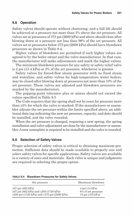
9.8 Operation
Safety valves should operate without chattering, and a full lift shouldbe achieved at a pressure not more than 3% above the set pressure. Allvalves set at pressures of 375 psi (2600 kPa) and above should close afterblowing down at a pressure not less than 96% of the set pressure. Allvalves set at pressures below 375 psi (2600 kPa) should have blowdownpressures as shown in Table 9.4.
Higher values of blowdown are permitted if such higher values areagreed to by the boiler owner and the valve manufacturer. In that case,the manufacturer will make adjustments and mark the higher values.
The minimum blowdown pressure for any safety or safety relief valveis 2 psi (13.4 kPa) or 2% of the set pressure, whichever is greater.
Safety valves for forced-flow steam generator with no fixed steamand waterline, and safety valves for high-temperature water boilers,may be closed after blowing down at pressures not more than 10% of theset pressure. These valves are adjusted and blowdown pressures aremarked by the manufacturers.
The popping-point tolerance plus or minus should not exceed thevalues specified in Table 9.5
The Code requires that the spring shall not be reset for pressure morethan ±5% for which the valve is marked. If the manufacturer or assem-bler adjusts the set pressure within the limits specified above, an addi-tional data tag indicating the new set pressure, capacity, and date shouldbe installed, and the valve resealed.
When the set pressure is changed, requiring a new spring, the springinstallation and valve adjustment are done by the manufacturer or assem-bler. A new nameplate is required to be installed and the valve is resealed.
9.9 Selection of Safety Valves
Proper selection of safety valves is critical to obtaining maximum pro-tection. Sufficient data should be made available to properly size andselect safety valves for specific applications. Safety valves are availablein a variety of sizes and materials. Each valve is unique and judgmentsare required in selecting the proper option.
Safety Valves for Power Boilers 201
TABLE 9.4 Blowdown Pressures for Safety Valves
Set pressure Maximum blowdown
<67 psi (462 kPa) 4 psi (14 kPa)≥67 psi (462 kPa) and ≤250 (1720 kPa) 6% of set pressure>250 psi (1720 kPa) and <375 psi (2590 kPa) 15 psi (103 kPa)
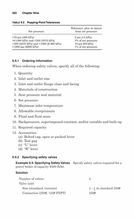
9.9.1 Ordering information
When ordering safety valves, specify all of the following:
1. Quantity
2. Inlet and outlet size
3. Inlet and outlet flange class and facing
4. Materials of construction
5. Seat pressure seal material
6. Set pressure
7. Maximum inlet temperature
8. Allowable overpressure
9. Fluid and fluid state
10. Backpressure, superimposed constant, and/or variable and built-up
11. Required capacity
12. Accessories:(a) Bolted cap, open or packed lever(b) Test gag(c) “L” lever(d) “R” lever
9.9.2 Specifying safety valves
Example 9.4: Specifying Safety Valves Specify safety valves required for apower boiler of capacity 6500 lb/hr.
Solution
Number of valves 2
Valve inlet
Size (standard, oversize) -in standard 250#
Connection (250#, 125# FNPT) 250#
1 − 12
202 Chapter Nine
TABLE 9.5 Popping-Point Tolerances
Tolerance, plus or minusSet pressure from set pressure
<70 psi (480 kPa) 2 psi (14 kPa)>0 (480 kPa) and <300 (2070 kPa) 3% of set pressure>300 (2070 kPa) and <1000 (6 900 kPa) 10 psi (69 kPa)>1000 psi (6900 kPa) 1% of set pressure

Set pressure 100 psig
Operating pressure 80 psig
Operating, relieving, and design temperatures 325°F/339°F/400°FBuilt-up back pressure 5 psig
Allowable overpressure 3%
Orifice size J
Required capacity 6500 PPH
ASME Boiler and Pressure Vessel Code ASME Sec. I
Trim (bronze, stainless) Stainless
Accessories (gag, spring cover, spring coating) Gag
Customer drawings (for approval, for record) For approval
Safety Valves for Power Boilers 203

This page intentionally left blank
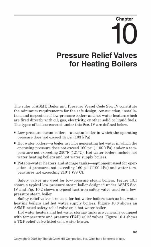
Chapter
Pressure Relief Valvesfor Heating Boilers
The rules of ASME Boiler and Pressure Vessel Code Sec. IV constitutethe minimum requirements for the safe design, construction, installa-tion, and inspection of low-pressure boilers and hot water heaters whichare fired directly with oil, gas, electricity, or other solid or liquid fuels.The types of boilers covered under this Sec. IV are defined below.
Low-pressure steam boilers—a steam boiler in which the operatingpressure does not exceed 15 psi (103 kPa).
Hot water boilers—a boiler used for generating hot water in which theoperating pressure does not exceed 160 psi (1100 kPa) and/or a tem-perature not exceeding 250°F (121°C). Hot water boilers include hotwater heating boilers and hot water supply boilers.
Potable-water heaters and storage tanks—equipment used for oper-ation at pressures not exceeding 160 psi (1100 kPa) and water tem-peratures not exceeding 210°F (99°C).
Safety valves are used for low-pressure steam boilers. Figure 10.1shows a typical low-pressure steam boiler designed under ASME Sec.IV and Fig. 10.2 shows a typical cast-iron safety valve used on a low-pressure steam boiler.
Safety relief valves are used for hot water boilers such as hot waterheating boilers and hot water supply boilers. Figure 10.3 shows anASME-rated safety relief valve on a hot water boiler.
Hot water heaters and hot water storage tanks are generally equippedwith temperature and pressure (T&P) relief valves. Figure 10.4 showsa T&P relief valve fitted on a water heater.
205
10
Copyright © 2006 by The McGraw-Hill Companies, Inc. Click here for terms of use.
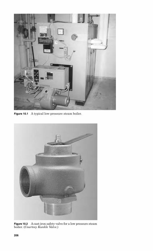
Figure 10.1 A typical low-pressure steam boiler.
Figure 10.2 A cast-iron safety valve for a low pressure steamboiler. (Courtesy Kunkle Valve.)
206
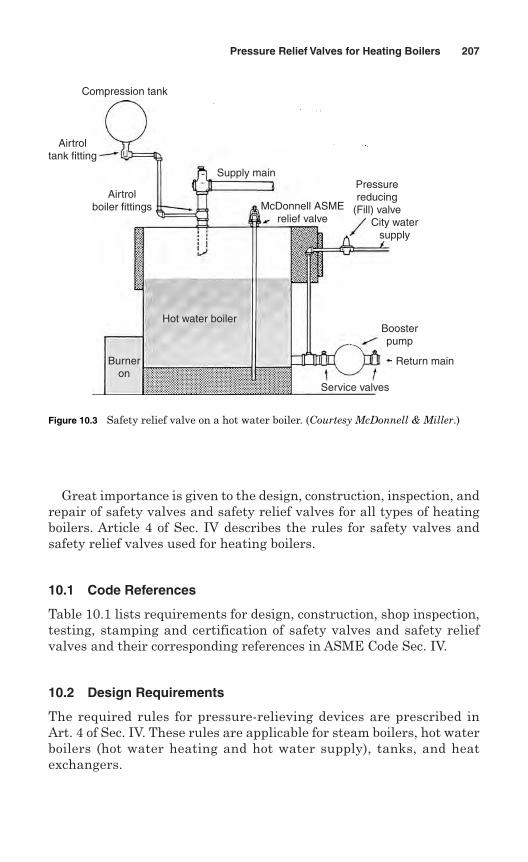
Great importance is given to the design, construction, inspection, andrepair of safety valves and safety relief valves for all types of heatingboilers. Article 4 of Sec. IV describes the rules for safety valves andsafety relief valves used for heating boilers.
10.1 Code References
Table 10.1 lists requirements for design, construction, shop inspection,testing, stamping and certification of safety valves and safety reliefvalves and their corresponding references in ASME Code Sec. IV.
10.2 Design Requirements
The required rules for pressure-relieving devices are prescribed inArt. 4 of Sec. IV. These rules are applicable for steam boilers, hot waterboilers (hot water heating and hot water supply), tanks, and heatexchangers.
Pressure Relief Valves for Heating Boilers 207
Compression tank
Airtroltank fitting
Airtrolboiler fittings
Supply main
McDonnell ASMErelief valve
Pressurereducing
(Fill) valveCity water
supply
Boosterpump
Return main
Service valves
Hot water boiler
Burneron
Figure 10.3 Safety relief valve on a hot water boiler. (Courtesy McDonnell & Miller.)
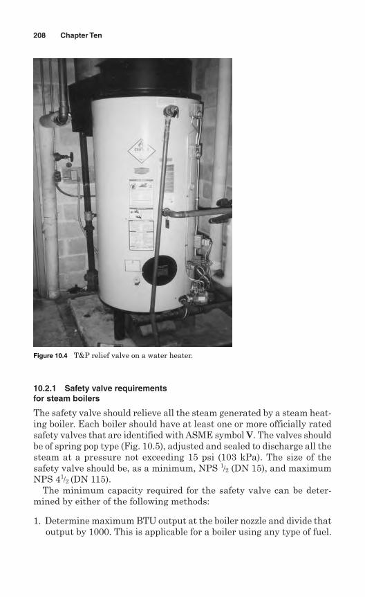
10.2.1 Safety valve requirementsfor steam boilers
The safety valve should relieve all the steam generated by a steam heat-ing boiler. Each boiler should have at least one or more officially ratedsafety valves that are identified with ASME symbol V. The valves shouldbe of spring pop type (Fig. 10.5), adjusted and sealed to discharge all thesteam at a pressure not exceeding 15 psi (103 kPa). The size of thesafety valve should be, as a minimum, NPS 1/2 (DN 15), and maximumNPS 41/2 (DN 115).
The minimum capacity required for the safety valve can be deter-mined by either of the following methods:
1. Determine maximum BTU output at the boiler nozzle and divide thatoutput by 1000. This is applicable for a boiler using any type of fuel.
208 Chapter Ten
Figure 10.4 T&P relief valve on a water heater.
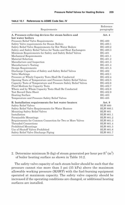
2. Determine minimum lb (kg) of steam generated per hour per ft2 (m2)of boiler heating surface as shown in Table 10.2.
The safety valve capacity of each steam boiler should be such that thepressure cannot rise more than 5 psi (35 kPa) above the maximumallowable working pressure (MAWP) with the fuel-burning equipmentoperated at maximum capacity. The safety valve capacity should beincreased if the operating conditions are changed, or additional heatingsurfaces are installed.
Pressure Relief Valves for Heating Boilers 209
TABLE 10.1 References to ASME Code Sec. IV
ReferenceRequirements paragraphs
A. Pressure-relieving devices for steam boilers and Art. 4hot water boilersPressure Relief Valve Requirements HG-400Safety Valve requirements for Steam Boilers HG-400.1Safety Relief Valve Requirements for Hot Water Boilers HG-400.2Safety and Safety Relief Valves for Tanks and Heat Exchangers HG-400.3Minimum Requirements for Safety and Safety Relief Valves HG-401Mechanical Requirements HG-401.1Material Selection HG-401.2Manufacture and Inspection HG-401.3Manufacturer’s Testing HG-401.4Design Requirements HG-401.5Discharge Capacities of Safety and Safety Relief Valves HG-402Valve Markings HG-402.1Pressure at Which Capacity Tests Shall Be Conducted HG-402.4Opening Tests of Temperature and Pressure Safety Relief Valves HG-402.5Capacity Tests of Temperature and Pressure Safety Relief Valves HG-402.6Fluid Medium for Capacity Tests HG-402.7Where and by Whom Capacity Tests Shall Be Conducted HG-402.8Test Record Data Sheet HG-402.9Heating Surface HG-403Temperature and Pressure Safety Relief Valves HG-405
B. Installation requirements for hot water heaters Art. 8Safety Relief Valves HLW-800Safety Relief Valve Requirements for Water Heaters HLW-800.1Mounting Safety Relief Valves HLW-801Installation HLW-801.1Permissible Mountings HLW-801.2Requirements for Common Connection for Two or More Valves HLW-801.3Threaded Connections HLW-801.4Prohibited Mountings HLW-801.5Use of Shutoff Valves Prohibited HLW-801.6Safety Relief Valve Discharge Piping HLW-801.7
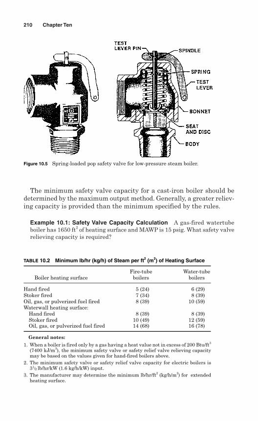
The minimum safety valve capacity for a cast-iron boiler should bedetermined by the maximum output method. Generally, a greater reliev-ing capacity is provided than the minimum specified by the rules.
Example 10.1: Safety Valve Capacity Calculation A gas-fired watertubeboiler has 1650 ft2 of heating surface and MAWP is 15 psig. What safety valverelieving capacity is required?
210 Chapter Ten
Figure 10.5 Spring-loaded pop safety valve for low-pressure steam boiler.
TABLE 10.2 Minimum lb/hr (kg/h) of Steam per ft2 (m2) of Heating Surface
Fire-tube Water-tubeBoiler heating surface boilers boilers
Hand fired 5 (24) 6 (29)Stoker fired 7 (34) 8 (39)Oil, gas, or pulverized fuel fired 8 (39) 10 (59)Waterwall heating surface:
Hand fired 8 (39) 8 (39)Stoker fired 10 (49) 12 (59)Oil, gas, or pulverized fuel fired 14 (68) 16 (78)
General notes:
1. When a boiler is fired only by a gas having a heat value not in excess of 200 Btu/ft3
(7400 kJ/m3), the minimum safety valve or safety relief valve relieving capacitymay be based on the values given for hand-fired boilers above.
2. The minimum safety valve or safety relief valve capacity for electric boilers is31/2 lb/hr/kW (1.6 kg/h/kW) input.
3. The manufacturer may determine the minimum lb/hr/ft2 (kg/h/m2) for extendedheating surface.
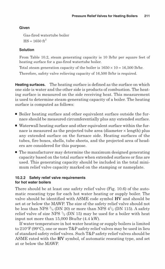
Given
Gas-fired watertube boiler
HS = 1650 ft2
Solution
From Table 10.2, steam generating capacity is 10 lb/hr per square feet ofheating surface for a gas-fired watertube boiler.
Total steam generation capacity of the boiler is 1650 × 10 = 16,500 lb/hr.
Therefore, safety valve relieving capacity of 16,500 lb/hr is required.
Heating surfaces. The heating surface is defined as the surface on whichone side is water and the other side is products of combustion. The heat-ing surface is measured on the side receiving heat. This measurementis used to determine steam-generating capacity of a boiler. The heatingsurface is computed as follows:
Boiler heating surface and other equivalent surface outside the fur-nace should be measured circumferentially plus any extended surface.
Waterwall heating surface and other equivalent surface within the fur-nace is measured as the projected tube area (diameter × length) plusany extended surface on the furnace side. Heating surfaces of thetubes, fire boxes, shells, tube sheets, and the projected area of head-ers are considered for this purpose.
The manufacturer may determine the maximum designed generatingcapacity based on the total surface when extended surfaces or fins areused. This generating capacity should be included in the total mini-mum relief valve capacity marked on the stamping or nameplate.
10.2.2 Safety relief valve requirementsfor hot water boilers
There should be at least one safety relief valve (Fig. 10.6) of the auto-matic reseating type for each hot water heating or supply boiler. Thevalve should be identified with ASME code symbol HV and should beset at or below the MAWP. The size of the safety relief valve should notbe less than NPS 3/4 (DN 20) or more than NPS 41/2 (DN 115). A safetyrelief valve of size NPS 1/2 (DN 15) may be used for a boiler with heatinput not more than 15,000 Btu/hr (4.4 kW).
If water temperature in hot water heating or supply boilers is limitedto 210°F (99°C), one or more T&P safety relief valves may be used in lieuof standard safety relief valves. Such T&P safety relief valves should beASME rated with the HV symbol, of automatic reseating type, and setat or below the MAWP.
Pressure Relief Valves for Heating Boilers 211
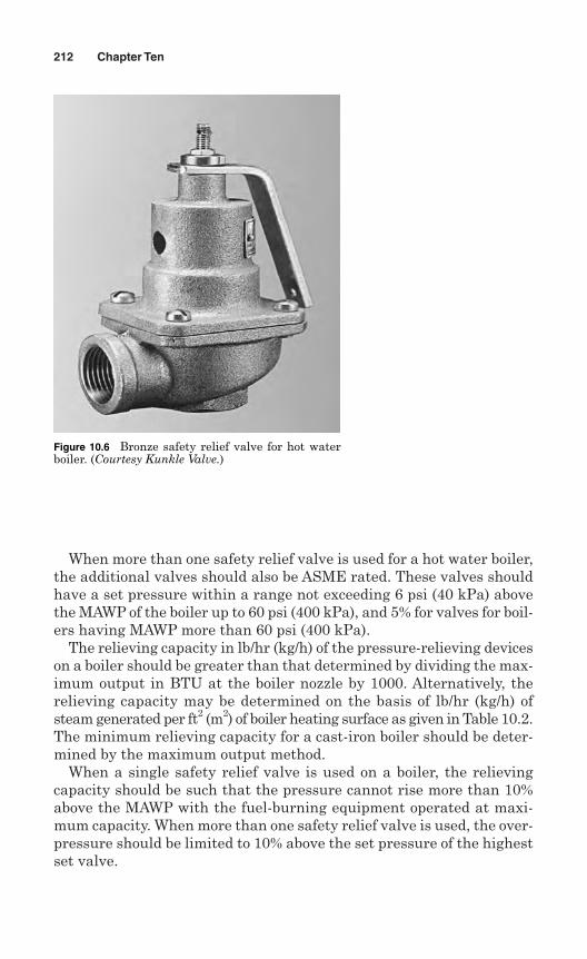
When more than one safety relief valve is used for a hot water boiler,the additional valves should also be ASME rated. These valves shouldhave a set pressure within a range not exceeding 6 psi (40 kPa) abovethe MAWP of the boiler up to 60 psi (400 kPa), and 5% for valves for boil-ers having MAWP more than 60 psi (400 kPa).
The relieving capacity in lb/hr (kg/h) of the pressure-relieving deviceson a boiler should be greater than that determined by dividing the max-imum output in BTU at the boiler nozzle by 1000. Alternatively, therelieving capacity may be determined on the basis of lb/hr (kg/h) ofsteam generated per ft2 (m2) of boiler heating surface as given in Table 10.2.The minimum relieving capacity for a cast-iron boiler should be deter-mined by the maximum output method.
When a single safety relief valve is used on a boiler, the relievingcapacity should be such that the pressure cannot rise more than 10%above the MAWP with the fuel-burning equipment operated at maxi-mum capacity. When more than one safety relief valve is used, the over-pressure should be limited to 10% above the set pressure of the highestset valve.
212 Chapter Ten
Figure 10.6 Bronze safety relief valve for hot waterboiler. (Courtesy Kunkle Valve.)
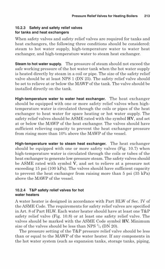
10.2.3 Safety and safety relief valvesfor tanks and heat exchangers
When safety valves and safety relief valves are required for tanks andheat exchangers, the following three conditions should be considered:steam to hot water supply, high-temperature water to water heatexchanger, and high-temperature water to steam heat exchanger.
Steam to hot water supply. The pressure of steam should not exceed thesafe working pressure of the hot water tank when the hot water supplyis heated directly by steam in a coil or pipe. The size of the safety reliefvalve should be at least NPS 1 (DN 25). The safety relief valve shouldbe set to relieve at or below the MAWP of the tank. The valve should beinstalled directly on the tank.
High-temperature water to water heat exchanger. The heat exchangershould be equipped with one or more safety relief valves when high-temperature water is circulated through the coils or pipes of the heatexchanger to heat water for space heating or hot water supply. Thesafety relief valves should be ASME rated with the symbol HV, and setat or below the MAWP of the heat exchanger. The valves should havesufficient relieving capacity to prevent the heat exchanger pressurefrom rising more than 10% above the MAWP of the vessel.
High-temperature water to steam heat exchanger. The heat exchangershould be equipped with one or more safety valves (Fig. 10.7) whenhigh-temperature water is circulated through the coils or tubes of theheat exchanger to generate low-pressure steam. The safety valves shouldbe ASME rated with symbol V, and set to relieve at a pressure notexceeding 15 psi (100 kPa). The valves should have sufficient capacityto prevent the heat exchanger from raising more than 5 psi (35 kPa)above the MAWP of the vessel.
10.2.4 T&P safety relief valves for hotwater heaters
A water heater is designed in accordance with Part HLW of Sec. IV ofthe ASME Code. The requirements for safety relief valves are specifiedin Art. 8 of Part HLW. Each water heater should have at least one T&Psafety relief valve (Fig. 10.8) or at least one safety relief valve. Thevalves should be marked with the ASME Code symbol HV. Minimumsize of the valves should be less than NPS 3/4 (DN 20).
The pressure setting of the T&P pressure relief valve should be lessthan or equal to the MAWP of the water heater. If any components inthe hot water system (such as expansion tanks, storage tanks, piping,
Pressure Relief Valves for Heating Boilers 213
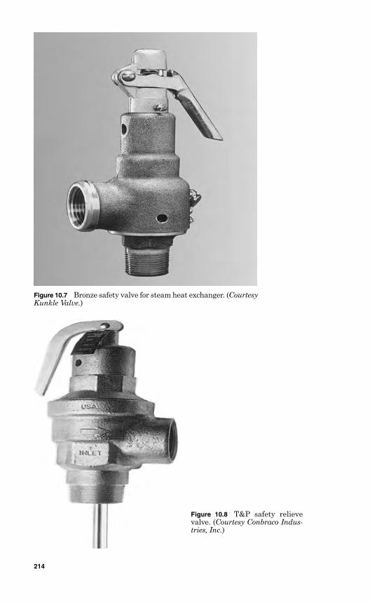
Figure 10.7 Bronze safety valve for steam heat exchanger. (CourtesyKunkle Valve.)
Figure 10.8 T&P safety relievevalve. (Courtesy Conbraco Indus-tries, Inc.)
214
etc.) have lower working pressure than the water heater, the valveshould be set at the pressure of the component with the lowest MAWP.If more than one valve is used, the additional valve may be set withina range not exceeding 10% over the set pressure of the first valve.
The relieving capacity in Btu/hr of the T&P safety relief valve shouldnot be less than the maximum allowable input of the water heater. Therelieving capacity for an electric heater should be 3500 Btu/hr (1.0 kW) perkW of input. The T&P safety relief valve capacity for each water heatershould be such that the pressure cannot rise more than 10% above theMAWP with the fuel-burning equipment operated at maximum capacity.
T&P safety relief valves should be installed by either the installer orthe manufacturer before a water heater is put into operation.
10.2.5 Mechanical requirements
The design of safety relief valves should incorporate guiding arrange-ments necessary to ensure consistent operation and tightness. Excessivelengths of guiding surfaces should be avoided. Bottom-guided designsare not allowed on safety relief valves. O-rings and other packingdevices, if used on the stems, should be arranged so that they do notaffect operation and capacity.
The inlet opening should have an inside diameter equal to or greaterthan the seat diameter. The maximum opening through any part of thevalve should not be less than 1/4 in (6 mm) in diameter.
The safety valves should be spring loaded and the spring should bedesigned so that the full-load spring compression is not greater than 80%of the nominal solid deflection. The permanent set of the spring shouldnot exceed 0.5% of the free height.
A body drain below seat level should be provided on all safety valvesand safety relief valves. For valves NPS 21/2 (DN 65) or smaller, the drainhole should be not less than 1/4 in (6 mm) in diameter. For valves largerthan NPS 21/2 (DN 65), the drain hole should be tapped to not less thanNPS 3/8 (DN 10). The body drain connections should not be pluggedduring or after installation.
Consideration should be given to minimizing the effects of waterdeposits when designing the body of the valve. The valves should be pro-vided with wrenching surfaces to allow installation without damagingoperating parts.
The safety valves should have a controlled blowdown of 2–4 psi(15–30 kPa), and this blowdown need not be adjustable. The set pres-sure tolerances, plus or minus, for safety valves should not exceed 2 psi(15 kPa), and for safety relief valves 3 psi (20 kPa) for pressures up to60 psig (400 kPa). These tolerances should not exceed 5% for pressuresabove 60 psig (400 kPa).
Pressure Relief Valves for Heating Boilers 215
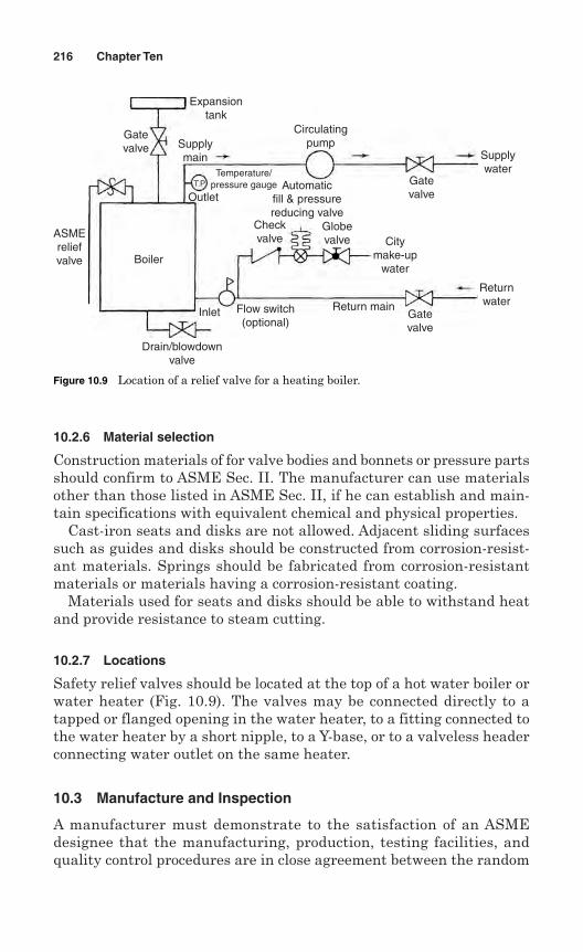
10.2.6 Material selection
Construction materials of for valve bodies and bonnets or pressure partsshould confirm to ASME Sec. II. The manufacturer can use materialsother than those listed in ASME Sec. II, if he can establish and main-tain specifications with equivalent chemical and physical properties.
Cast-iron seats and disks are not allowed. Adjacent sliding surfacessuch as guides and disks should be constructed from corrosion-resist-ant materials. Springs should be fabricated from corrosion-resistantmaterials or materials having a corrosion-resistant coating.
Materials used for seats and disks should be able to withstand heatand provide resistance to steam cutting.
10.2.7 Locations
Safety relief valves should be located at the top of a hot water boiler orwater heater (Fig. 10.9). The valves may be connected directly to atapped or flanged opening in the water heater, to a fitting connected tothe water heater by a short nipple, to a Y-base, or to a valveless headerconnecting water outlet on the same heater.
10.3 Manufacture and Inspection
A manufacturer must demonstrate to the satisfaction of an ASMEdesignee that the manufacturing, production, testing facilities, andquality control procedures are in close agreement between the random
216 Chapter Ten
Gatevalve
ASMEreliefvalve Boiler
Inlet
Drain/blowdownvalve
Flow switch(optional)
Outlet
Supplymain
Expansiontank
Circulatingpump
Gatevalve
Citymake-up
water
Gatevalve
Returnwater
Supplywater
Automaticfill & pressurereducing valve
Temperature/pressure gauge
Return main
Globevalve
Checkvalve
T.P
Figure 10.9 Location of a relief valve for a heating boiler.
production samples and the valves submitted for capacity certification.An ASME designee can inspect manufacturing, inspection, and testoperations including capacity at any time.
Each safety relief valve to which the Code symbol HV is to be appliedmust be produced by a manufacturer and/or assembler who is in pos-session of a valid Certificate of Authorization. A manufacturer or assem-bler may be granted permission by the ASME to produce pressure reliefvalves with Code symbol HV upon acceptance of a satisfactory recom-mendation from the ASME designee and payment of administrativefees. The permission expires on the fifth anniversary of the date it is ini-tially granted.
In order to extend permission for 5-year periods, a manufacturer isrequired to successfully repeat the following tests within the 6-monthperiod before expiration:
1. Two sample production pressure relief valves of a size and capacitywithin the capability of an ASME-accepted laboratory are selected byan ASME designee.
2. An ASME-accepted laboratory then conducts operational and capac-ity tests in the presence of an ASME designee. The valve manufac-turer may have representatives present to witness the tests.
3. If any valve fails to relieve at or above its certified capacity or failsto meet performance criteria, the test is repeated at the rate of tworeplacement valves for each valve that failed.
4. If any of the replacement valves fails to meet the capacity or perform-ance requirements, the manufacturer’s Code symbol for the particulartype of valve will be revoked within 60 days of the authorization. Duringthis period, the manufacturer should demonstrate the cause of suchdeficiency and the action taken to guard against future occurrence.
Safety valves should be sealed to prevent the valve from being takenapart without breaking the seal. Safety relief valves should be set andsealed so that they cannot be reset without breaking the seal.
10.3.1 Valve markings
A manufacturer and/or assembler should posses a valid Certification ofAuthorization from the ASME to apply a Code symbol to each safetyrelief valve. Each safety relief valve is required to be marked with thedata as per Par. HG-402.1 of Sec. IV, and markings should include thefollowing:
1. Name or acceptable abbreviation of the manufacturer’s name.
2. Manufacturer’s design or type number.
Pressure Relief Valves for Heating Boilers 217
3. NPS size _______ in (DN) (the nominal pipe size of the valve inlet).
4. Set pressure ____________ psi.
5. Capacity ________ lb/hr (kg/h), or capacity __________ Btu/hr.
6. Year built. Alternatively, a coding may be marked on the valves suchthat the valve manufacturer can identify the year the valve wasassembled and tested.
7. ASME Symbol as shown in Fig. 10.10.
The above data should be marked in such a way that the markingswill not be obliterated in service over a period of time. The markings maybe stamped, etched, impressed, or cast on the valve or on a nameplate,which should be securely fastened to the valve (Fig. 10.11).
10.4 Manufacturer’s Testing
A manufacturer should have a well-established program for testing safetyvalves and safety relief valves. The testing program should be establishedfor the application, calibration, and maintenance of test gauges.
Each safety valve should be tested to demonstrate its poppingpoint, blowdown, and tightness. Each safety relief valve should betested to demonstrate its opening point and tightness. Safety valvesare tested on steam or air and safety relief valves are tested on water,steam, or air.
Depending on size and design, testing time will vary, but testing timeshould be sufficient to ensure that test results are repeatable and rep-resent field performance. Test fixtures and test drums should of ade-quate size and capacity to assure accurate pop action and blowdownadjustment.
The tightness test is very important for safety relief valves. A tight-ness test is conducted at maximum expected operating pressure, notexceeding the reseating pressure of the valve.
218 Chapter Ten
Figure 10.10 ASME symbolfor a safety relief valve.
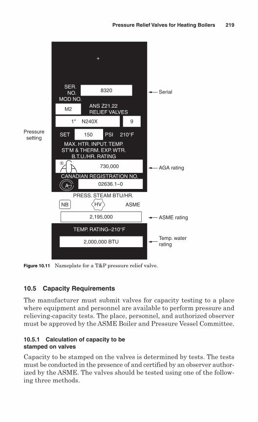
10.5 Capacity Requirements
The manufacturer must submit valves for capacity testing to a placewhere equipment and personnel are available to perform pressure andrelieving-capacity tests. The place, personnel, and authorized observermust be approved by the ASME Boiler and Pressure Vessel Committee.
10.5.1 Calculation of capacity to bestamped on valves
Capacity to be stamped on the valves is determined by tests. The testsmust be conducted in the presence of and certified by an observer author-ized by the ASME. The valves should be tested using one of the follow-ing three methods.
Pressure Relief Valves for Heating Boilers 219
Pressuresetting
SER. NO.
MOD NO.
8320
M2ANS Z21.22RELIEF VALVES
1" N240X 9
SET 150 PSI 210°F
MAX. HTR. INPUT. TEMP.ST’M & THERM. EXP. WTR.
B.T.U./HR. RATING
CANADIAN REGISTRATION NO.
PRESS. STEAM BTU/HR.
ASMEHVNB
2,195,000
TEMP. RATING–210°F
2,000,000 BTUTemp. waterrating
ASME rating
AGA rating
A
Serial
+
730,000
02636.1–0
Figure 10.11 Nameplate for a T&P pressure relief valve.
Coefficient method. This coefficient method is based on coefficient cal-culation and is used for safety relief valves. In this method, tests are con-ducted to determine the lift, popping, and blowdown pressures, and thecapacity of at least three valves each of three representative sizes (a totalof nine valves). Each valve should be set at a different pressure.However, safety valves for low-pressure steam boilers should have allnine valves set at 15 psig (100 kPa).
A coefficient of discharge, KD, is established for each test using the fol-lowing formula:
where the average of coefficients KD of the nine tests is determined as
K = average KD × 0.90
where K is the coefficient of discharge for the design.
The stamped capacities for all sizes and pressures are determinedusing the following formulas.
For a 45° seat,
For a flat seat,
For a nozzle,
where W = weight of steam per hour, lbD = seat diameter, inL = lift, inP = (1.10 × set pressure + 14.7) psia for hot water applications
= (5.0 psi = 15 psi set + 14.7) psia for steam boilersA = nozzle throat area, in2
The maximum and minimum coefficients determined by the testsof a valve design should not vary more than ±5% from the average. Ifone or more tests are outside the acceptable limits, one valve of the
W APK= 51 5.
W DLPK= 51 5. π
W DLP K= ×51 5 0 707. .p
KD = Actual steam flowTheoretical steam flow
220 Chapter Ten
manufacturer’s choice should be replaced with another valve of thesame size and pressure setting or by a modification of the original valve.A new average coefficient should be calculated, excluding the replacedvalve. If one or more tests are now outside the acceptable limits, asdetermined by the new average coefficient, a valve of the manufac-turer’s choice should be replaced by two valves of the same size and pres-sure as the rejected valve. A new average coefficient, including thereplacement valves, should be calculated. If any valve, excluding the tworeplaced valves, now falls outside the acceptable limits, the test is con-sidered unsatisfactory.
Slope method. The slope method is used to apply the ASME Codesymbol to a design of pressure relief valves. In this method, four valvesof each combination of pipe and orifice size are tested. These four valvesshould be set at pressures to cover the range of pressures for which thevalves will be used. The capacities should be based on these four testsas given below.
1. The slope (W/P) for each test should be calculated using the follow-ing formula:
All values obtained from the testing should fall with ±5% of theaverage value:
Minimum slope = 0.95 × average slope
Maximum slope= 1.05 × average slope
The test values should be between the minimum and maximumslope value range. The authorized observer may require that addi-tional valves be tested at the rate of two for each valve beyond themaximum values, with a limit of four additional valves.
2. The relieving capacity to be stamped on the valve should not exceed90% of the average slope × the absolute accumulation pressure:
Rated slope = 0.90 × average slope
Stamped capacity ≥ rated slope × (1.10 × set pressure + 14.7 psia)
for hot water applications.
Slopemeasured capacity,lb/hr
absoluteflowpressure,psia= =W
P
Pressure Relief Valves for Heating Boilers 221
Three-valve method. The three-valve method is used when a manufac-turer intends to apply the Code symbol to safety relief valves of one ormore sizes of a design set at one pressure. The manufacturer shouldsubmit three valves of each size of each design set at one pressure fortesting. In this case the stamped capacity should not exceed 90% of theaverage capacity of the three valves tested.
The discharge capacity as determined by the test of each valve testedshould not vary more than ±5% from the average capacity of the threevalves tested. If one of the three valve tests falls outside the limits, itmay be replaced by two valves and a new average calculated based onall four valves, excluding the replaced valve.
10.5.2 Fluid medium for tests
The tests should be performed with dry saturated steam. This steammay contain 98% quality and 20°F (10°C) maximum superheat. Therelieving capacity should be measured by condensing the steam or witha calibrated steam flow meter.
In order to determine the discharge capacity of safety relief valves,steam flow per hour is measured. The discharge capacity in terms of Btuis obtained by steam flow per hour W multiplied by 1000.
10.5.3 Capacity tests of T&P safetyrelief valves
For determining the capacity of T&P safety relief valves, dummy ele-ments of the same size and shape are used instead of thermal elements,and the relieving capacity is based on the pressure element only. Themanufacturer should deactivate the temperature element of the pro-duction test valves prior to or at the time of capacity testing.
For determining the set (opening) pressure, the test medium shouldbe water at room temperature. The actual set pressure is defined asthe pressure at the valve inlet when the flow rate through the valveis 40 cm3/min. Capacity tests should be performed with steam at apressure 10% above the actual water set pressure. For productioncapacity tests, the rated capacity should be based on the actual waterset pressure.
10.5.4 Capacity tests for safety and safetyrelief valves
Safety valves and safety relief valves are tested for conformance to therequirements of ASME PTC 25. The tests are performed at a placewhere the testing facilities, methods, procedures, and person supervis-ing the tests meet the requirements of ASME PTC 25.
222 Chapter Ten
Safety valves should be tested for capacity at 5 psi (35 kPa) over theset pressure for which the valve is set to operate. Capacity tests for safetyrelief valves for hot water heating and hot water supply boilers should beperformed at 110% of the pressure for which the valve is set to operate.
The tests should be conducted under the supervision of and certifiedby an Authorized Observer (AO). The testing facilities, methods, proce-dures, and qualifications of the AO should be approved by the ASME onrecommendation of an ASME designee. The testing facilities are subjectto review by ASME within each 5-year period.
The manufacturer and the AO should sign the capacity test datareports for each model, type, and size of valve. The signed test datareports are submitted to the ASME designee for review and acceptance.When any changes are made in the valve design, capacity certificationtests should be repeated.
10.5.5 Test record data sheets
A data sheet for each valve is prepared and signed by the AO witnessingthe test. The manufacturer will use that data sheet for construction andstamping the valves of the corresponding design and construction. Newtests should be conducted when changes are made in the design thataffects the flow path, lift, or performance characteristics of the valve.
Pressure Relief Valves for Heating Boilers 223

This page intentionally left blank
Chapter
Pressure Relief Devicesfor Pressure Vessels
Apressure vessel is a closed container designed for the containment of pres-sure, either internal or external. The pressure may be imposed by anexternal source, by the application of heat from a direct or indirect source,or by any combination thereof. Pressure vessels are usually subjected toan internal or external operating pressure of more than 15 psig (103 kPa).
Internal pressure in a vessel is developed from the fluid in processapplications. External pressure on a vessel may be imposed by an inter-nal vacuum or by pressure of the fluid between an outer jacket and thevessel wall. The components of a vessel may fail, causing dangerous acci-dents if the vessel cannot withstand the internal or external pressure.
Pressure vessels are designed and constructed in various shapes.They may be cylindrical with heads, spherical, spheroidal, boxed, orlobed. The common types of pressure vessels are boilers, water heaters,expansion tanks, feedwater heaters, columns, towers, drums, reactors,heat exchangers, condensers, air coolers, oil coolers, accumulators, airtanks, gas cylinders, and refrigeration systems.
11.1 Introduction
Pressure vessels contain fluids such as liquids, vapors, and gases atpressure levels greater than atmospheric pressure. Some of the fluidsmay be corrosive or toxic. All types of industries, from workshops topower generation, pulp and paper to large petrochemical industries,use pressure vessels. Small workshops use air compressor tanks.Petrochemical industries use hundreds of vessels such as towers, drums,reactors etc., for process applications. Depending on the application,the vessels are constructed of either carbon steel or alloy steel.
225
11
Copyright © 2006 by The McGraw-Hill Companies, Inc. Click here for terms of use.
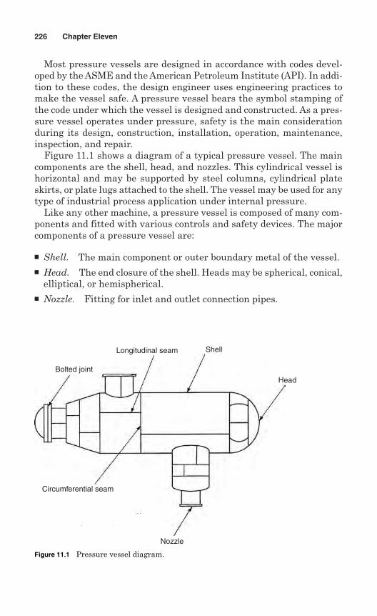
Most pressure vessels are designed in accordance with codes devel-oped by the ASME and the American Petroleum Institute (API). In addi-tion to these codes, the design engineer uses engineering practices tomake the vessel safe. A pressure vessel bears the symbol stamping ofthe code under which the vessel is designed and constructed. As a pres-sure vessel operates under pressure, safety is the main considerationduring its design, construction, installation, operation, maintenance,inspection, and repair.
Figure 11.1 shows a diagram of a typical pressure vessel. The maincomponents are the shell, head, and nozzles. This cylindrical vessel ishorizontal and may be supported by steel columns, cylindrical plateskirts, or plate lugs attached to the shell. The vessel may be used for anytype of industrial process application under internal pressure.
Like any other machine, a pressure vessel is composed of many com-ponents and fitted with various controls and safety devices. The majorcomponents of a pressure vessel are:
Shell. The main component or outer boundary metal of the vessel. Head. The end closure of the shell. Heads may be spherical, conical,
elliptical, or hemispherical. Nozzle. Fitting for inlet and outlet connection pipes.
226 Chapter Eleven
Bolted joint
Longitudinal seam Shell
Head
Nozzle
Circumferential seam
Figure 11.1 Pressure vessel diagram.
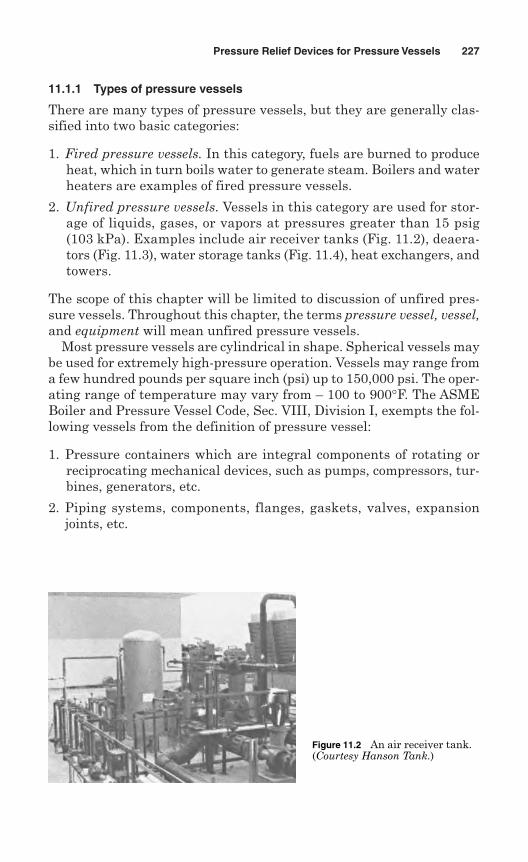
11.1.1 Types of pressure vessels
There are many types of pressure vessels, but they are generally clas-sified into two basic categories:
1. Fired pressure vessels. In this category, fuels are burned to produceheat, which in turn boils water to generate steam. Boilers and waterheaters are examples of fired pressure vessels.
2. Unfired pressure vessels. Vessels in this category are used for stor-age of liquids, gases, or vapors at pressures greater than 15 psig(103 kPa). Examples include air receiver tanks (Fig. 11.2), deaera-tors (Fig. 11.3), water storage tanks (Fig. 11.4), heat exchangers, andtowers.
The scope of this chapter will be limited to discussion of unfired pres-sure vessels. Throughout this chapter, the terms pressure vessel, vessel,and equipment will mean unfired pressure vessels.
Most pressure vessels are cylindrical in shape. Spherical vessels maybe used for extremely high-pressure operation. Vessels may range froma few hundred pounds per square inch (psi) up to 150,000 psi. The oper-ating range of temperature may vary from – 100 to 900°F. The ASMEBoiler and Pressure Vessel Code, Sec. VIII, Division I, exempts the fol-lowing vessels from the definition of pressure vessel:
1. Pressure containers which are integral components of rotating orreciprocating mechanical devices, such as pumps, compressors, tur-bines, generators, etc.
2. Piping systems, components, flanges, gaskets, valves, expansionjoints, etc.
Pressure Relief Devices for Pressure Vessels 227
Figure 11.2 An air receiver tank.(Courtesy Hanson Tank.)
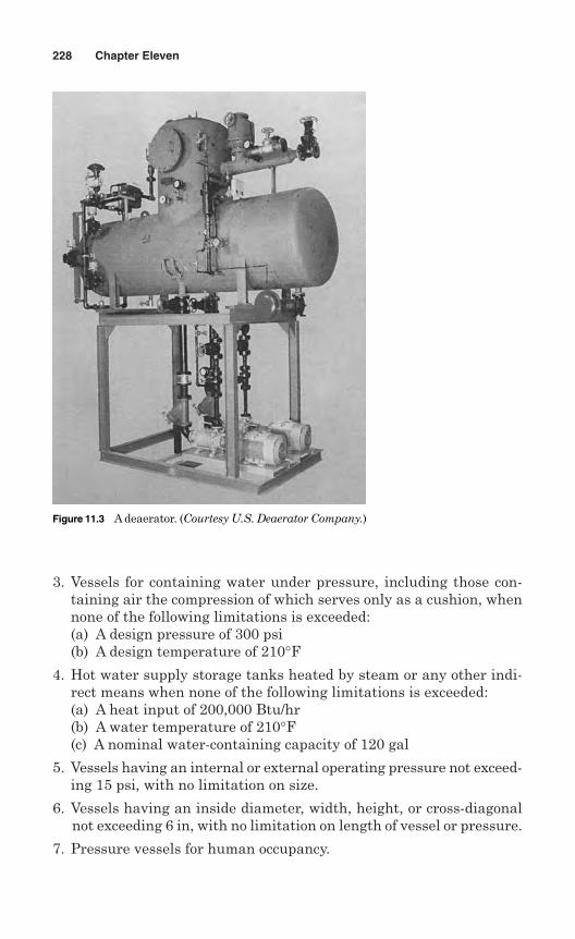
3. Vessels for containing water under pressure, including those con-taining air the compression of which serves only as a cushion, whennone of the following limitations is exceeded:(a) A design pressure of 300 psi(b) A design temperature of 210°F
4. Hot water supply storage tanks heated by steam or any other indi-rect means when none of the following limitations is exceeded:(a) A heat input of 200,000 Btu/hr(b) A water temperature of 210°F(c) A nominal water-containing capacity of 120 gal
5. Vessels having an internal or external operating pressure not exceed-ing 15 psi, with no limitation on size.
6. Vessels having an inside diameter, width, height, or cross-diagonalnot exceeding 6 in, with no limitation on length of vessel or pressure.
7. Pressure vessels for human occupancy.
228 Chapter Eleven
Figure 11.3 A deaerator. (Courtesy U.S. Deaerator Company.)
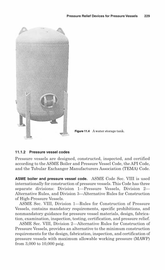
11.1.2 Pressure vessel codes
Pressure vessels are designed, constructed, inspected, and certifiedaccording to the ASME Boiler and Pressure Vessel Code, the API Code,and the Tubular Exchanger Manufacturers Association (TEMA) Code.
ASME boiler and pressure vessel code. ASME Code Sec. VIII is usedinternationally for construction of pressure vessels. This Code has threeseparate divisions: Division 1—Pressure Vessels, Division 2—Alternative Rules, and Division 3—Alternative Rules for Constructionof High-Pressure Vessels.
ASME Sec. VIII, Division 1—Rules for Construction of PressureVessels, contains mandatory requirements, specific prohibitions, andnonmandatory guidance for pressure vessel materials, design, fabrica-tion, examination, inspection, testing, certification, and pressure relief.
ASME Sec. VIII, Division 2—Alternative Rules for Construction ofPressure Vessels, provides an alternative to the minimum constructionrequirements for the design, fabrication, inspection, and certification ofpressure vessels with maximum allowable working pressure (MAWP)from 3,000 to 10,000 psig.
Pressure Relief Devices for Pressure Vessels 229
Figure 11.4 A water storage tank.
ASME Sec. VIII, Division 3—Alternative Rules for Construction ofHigh-Pressure Vessels, are applicable to the design, construction, inspec-tion, and overpressure protection of metallic pressure vessels withdesign pressures generally above 10,000 psi.
American Petroleum Institute Code. API 510, Pressure Vessel InspectionCode, is widely used in the petroleum and chemical process industriesfor maintenance inspection, rating, repair, and alteration of pressurevessels. This code is applicable only to vessels that have been placed inservice and have been inspected by an authorized inspection agency orhave been repaired by a repair organization defined in the code. The codeincludes provisions for certifying pressure vessel inspectors.
API Standard 572, Inspection of Pressure Vessels, is a RecommendedPractice (RP) standard for inspection of pressure vessels (towers, drums,reactors, heat exchangers, and condensers). The standard covers the rea-sons for inspection, causes of deterioration, frequency and methods ofinspection, methods of repair, and preparation of records and reports.
API Standard 620, Recommended Rules for Design and Constructionof Large, Welded, Low-Pressure Storage Tanks, provides rules for designand construction of large, welded, low-pressure carbon steel abovegroundstorage tanks. The tanks are designed for metal temperature not greaterthan 250°F and with pressures in their gas or vapor spaces not greaterthan 15 psig. These are low-pressure vessels that are not covered byASME Sec. VIII, Division 1 Code.
API Standard 650, Welded Steel Tanks for Oil Storage, covers mate-rial, design, fabrication, erection, and testing requirements for above-ground, vertical cylindrical, closed- and open-top, welded steel storagetanks in various sizes and capacities. This standard is applicable totanks with internal pressures of approximately atmospheric pressure,but higher pressure is permitted when additional requirements are met.
API Standard 660, Shell-and-Tube Heat Exchangers for GeneralRefinery Services, defines the minimum requirements for the mechan-ical design, material selection, fabrication, inspection, testing, andpreparation for shipment of shell-and-tube heat exchangers for generalrefinery services.
API Standard 661, Air-Cooled Heat Exchangers for General RefineryService, covers the minimum requirements for design, materials, fab-rication, inspection, testing, and preparation for shipment of refineryprocess air-cooled heat exchangers.
TEMA standards. The Tubular Exchanger Manufacturers Association(TEMA) includes manufacturers of shell-and-tube heat exchangers. TheTEMA Standards cover nomenclature, fabrication tolerance, generalfabrication and performance information, installation, operation and
230 Chapter Eleven
maintenance, mechanical standard class RCB heat exchangers, flow-induced vibration, thermal relations, physical properties of fluids, andrecommended good practice for shell-and-tube heat exchangers.
11.1.3 Pressure relief devices
All pressure vessels as defined by ASME Sec. VIII, regardless of sizeor pressure, should be provided with pressure relief devices such aspressure relief valves or nonreclosing pressure relief devices such asrupture disks. It is the responsibility of the owner to ensure that pres-sure relief devices are properly installed prior to operation. The pressurerelief devices may be installed either by the vessel manufacturer or byan installing contractor.
The pressure relief devices should protect the pressure vessels, pre-venting pressure rising more than 10% or 3 psi (20 kPa), whichever isgreater, above the MAWP. If multiple pressure relief devices are used,they should prevent the pressure from rising more than 16% or 4 psi(30 kPa), whichever is greater, above the MAWP.
If additional hazard is expected to be created by exposure of a pres-sure vessel to fire or other unexpected sources of external heat, sup-plemental pressure relief devices should be installed to protect againstexcessive pressure. Such supplemental devices should be capable of pre-venting the pressure from rising more than 21% above the MAWP.
Vessels that are operated completely filled with liquid should be pro-vided with pressure relief devices designed for liquid service, unlessotherwise protected against overpressure.
Pressure relief devices should be constructed, located, and installedso that they are readily accessible for inspection, replacement, andrepair. Pressure relief devices need not be installed directly on a pres-sure vessel when either of the following conditions applies:
The source of pressure is external to the vessel and under control, so thatthe pressure cannot exceed the MAWP at the operating temperature.
There are no intervening stop valves between the vessel and the pres-sure relief devices.
11.2 Pressure Relief Valves
A pressure relief valve is a pressure relief device which is designed toreclose and prevent the further flow of fluid after normal conditionshave been restored. Safety, safety relief, and relief valves are examplesof pressure relief valves and are used for all types of pressure vessels.Figure. 11.5 shows two water storage tanks connected together; eachwater storage tank is fitted with a T & P relief valve.
Pressure Relief Devices for Pressure Vessels 231
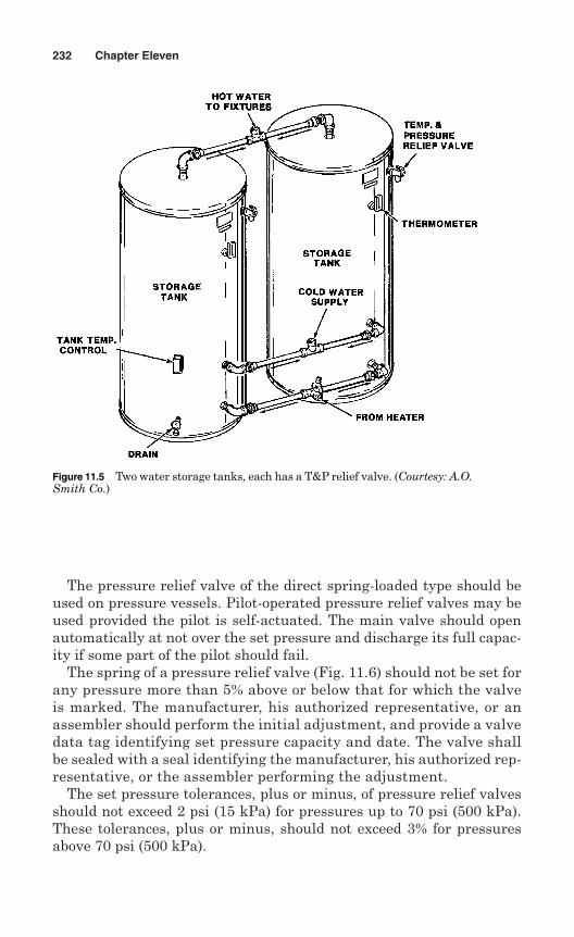
The pressure relief valve of the direct spring-loaded type should beused on pressure vessels. Pilot-operated pressure relief valves may beused provided the pilot is self-actuated. The main valve should openautomatically at not over the set pressure and discharge its full capac-ity if some part of the pilot should fail.
The spring of a pressure relief valve (Fig. 11.6) should not be set forany pressure more than 5% above or below that for which the valveis marked. The manufacturer, his authorized representative, or anassembler should perform the initial adjustment, and provide a valvedata tag identifying set pressure capacity and date. The valve shallbe sealed with a seal identifying the manufacturer, his authorized rep-resentative, or the assembler performing the adjustment.
The set pressure tolerances, plus or minus, of pressure relief valvesshould not exceed 2 psi (15 kPa) for pressures up to 70 psi (500 kPa).These tolerances, plus or minus, should not exceed 3% for pressuresabove 70 psi (500 kPa).
232 Chapter Eleven
Figure 11.5 Two water storage tanks, each has a T&P relief valve. (Courtesy: A.O.Smith Co.)
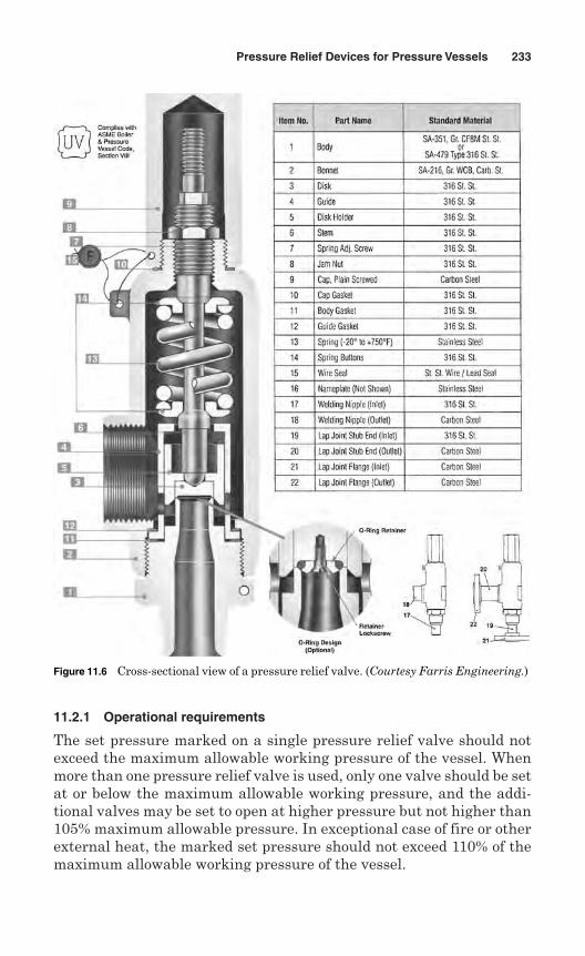
11.2.1 Operational requirements
The set pressure marked on a single pressure relief valve should notexceed the maximum allowable working pressure of the vessel. Whenmore than one pressure relief valve is used, only one valve should be setat or below the maximum allowable working pressure, and the addi-tional valves may be set to open at higher pressure but not higher than105% maximum allowable pressure. In exceptional case of fire or otherexternal heat, the marked set pressure should not exceed 110% of themaximum allowable working pressure of the vessel.
Pressure Relief Devices for Pressure Vessels 233
Figure 11.6 Cross-sectional view of a pressure relief valve. (Courtesy Farris Engineering.)
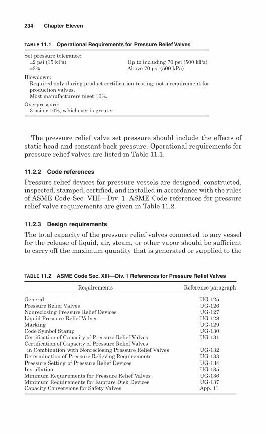
The pressure relief valve set pressure should include the effects ofstatic head and constant back pressure. Operational requirements forpressure relief valves are listed in Table 11.1.
11.2.2 Code references
Pressure relief devices for pressure vessels are designed, constructed,inspected, stamped, certified, and installed in accordance with the rulesof ASME Code Sec. VIII—Div. 1. ASME Code references for pressurerelief valve requirements are given in Table 11.2.
11.2.3 Design requirements
The total capacity of the pressure relief valves connected to any vesselfor the release of liquid, air, steam, or other vapor should be sufficientto carry off the maximum quantity that is generated or supplied to the
234 Chapter Eleven
TABLE 11.1 Operational Requirements for Pressure Relief Valves
Set pressure tolerance:±2 psi (15 kPa) Up to including 70 psi (500 kPa)±3% Above 70 psi (500 kPa)
Blowdown:Required only during product certification testing; not a requirement forproduction valves.Most manufacturers meet 10%.
Overpressure:3 psi or 10%, whichever is greater.
TABLE 11.2 ASME Code Sec. XIII––Div. 1 References for Pressure Relief Valves
Requirements Reference paragraph
General UG-125Pressure Relief Valves UG-126Nonreclosing Pressure Relief Devices UG-127Liquid Pressure Relief Valves UG-128Marking UG-129Code Symbol Stamp UG-130Certification of Capacity of Pressure Relief Valves UG-131Certification of Capacity of Pressure Relief Valves in Combination with Nonreclosing Pressure Relief Valves UG-132
Determination of Pressure Relieving Requirements UG-133Pressure Setting of Pressure Relief Devices UG-134Installation UG-135Minimum Requirements for Pressure Relief Valves UG-136Minimum Requirements for Rupture Disk Devices UG-137Capacity Conversions for Safety Valves App. 11
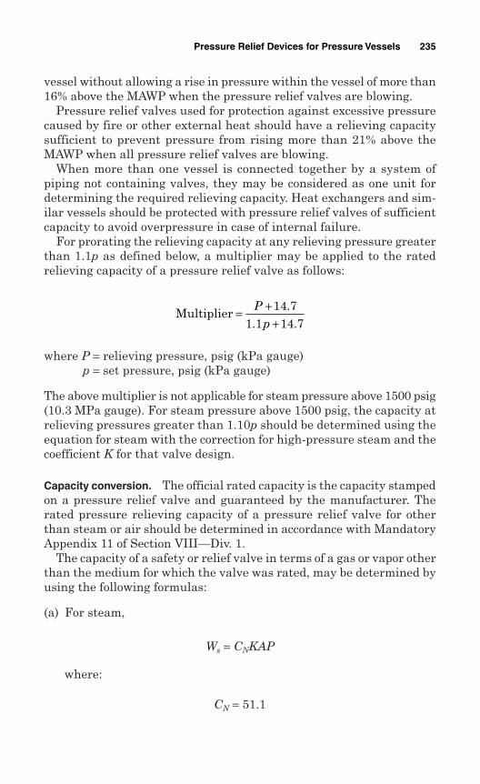
vessel without allowing a rise in pressure within the vessel of more than16% above the MAWP when the pressure relief valves are blowing.
Pressure relief valves used for protection against excessive pressurecaused by fire or other external heat should have a relieving capacitysufficient to prevent pressure from rising more than 21% above theMAWP when all pressure relief valves are blowing.
When more than one vessel is connected together by a system ofpiping not containing valves, they may be considered as one unit fordetermining the required relieving capacity. Heat exchangers and sim-ilar vessels should be protected with pressure relief valves of sufficientcapacity to avoid overpressure in case of internal failure.
For prorating the relieving capacity at any relieving pressure greaterthan 1.1p as defined below, a multiplier may be applied to the ratedrelieving capacity of a pressure relief valve as follows:
where P = relieving pressure, psig (kPa gauge)p = set pressure, psig (kPa gauge)
The above multiplier is not applicable for steam pressure above 1500 psig(10.3 MPa gauge). For steam pressure above 1500 psig, the capacity atrelieving pressures greater than 1.10p should be determined using theequation for steam with the correction for high-pressure steam and thecoefficient K for that valve design.
Capacity conversion. The official rated capacity is the capacity stampedon a pressure relief valve and guaranteed by the manufacturer. Therated pressure relieving capacity of a pressure relief valve for otherthan steam or air should be determined in accordance with MandatoryAppendix 11 of Section VIII—Div. 1.
The capacity of a safety or relief valve in terms of a gas or vapor otherthan the medium for which the valve was rated, may be determined byusing the following formulas:
(a) For steam,
Ws = CNKAP
where:
CN = 51.1
Multiplier = ++
Pp
14 71 1 14 7
.. .
Pressure Relief Devices for Pressure Vessels 235
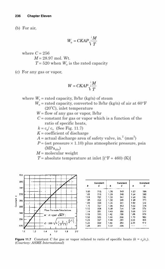
(b) For air,
where C = 256M = 28.97 mol. Wt.T = 520 when Wa is the rated capacity
(c) For any gas or vapor,
where Ws = rated capacity, lb/hr (kg/n) of steamWa = rated capacity, converted to lb/hr (kg/n) of air at 60°F
(20oC), inlet temperatureW = flow of any gas or vapor, lb/hrC = constant for gas or vapor which is a function of the
ratio of specific heats,k = cp/ cv (See Fig. 11.7)K = coefficient of dischargeA = actual discharge area of safety valve, in.2 (mm2)P = (set pressure × 1.10) plus atmospheric pressure, psia
(MPaabs)M = molecular weightT = absolute temperature at inlet [(°F + 460) (K)]
W CKAPMT
=
W CKAPMTa =
236 Chapter Eleven
Figure 11.7 Constant C for gas or vapor related to ratio of specific heats (k = cp/cv).(Courtesy: ASME International)
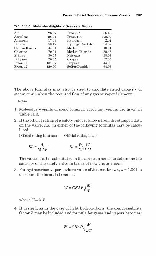
The above formulas may also be used to calculate rated capacity ofsteam or air when the required flow of any gas or vapor is known,
Notes
1. Molecular weights of some common gases and vapors are given inTable 11.3.
2. If the official rating of a safety valve is known from the stamped dataon the valve, KA in either of the following formulas may be calcu-lated:Official rating in steam Official rating in air
The value of KA is substituted in the above formulas to determine thecapacity of the safety valve in terms of new gas or vapor.
3. For hydrocarbon vapors, where value of k is not known, k = 1.001 isused and the formula becomes:
where C = 315
4. If desired, as in the case of light hydrocarbons, the compressibilityfactor Z may be included and formula for gases and vapors becomes:
W CKAPMZT
=
W CKAPMT
=
KAW
CP
T
Ma=KA
W
Ps=
51 5.
Pressure Relief Devices for Pressure Vessels 237
TABLE 11.3 Molecular Weights of Gases and Vapors
Air 28.97 Freon 22 86.48Acetylene 26.04 Freon 114 170.90Ammonia 17.03 Hydrogen 2.02Butane 58.12 Hydrogen Sulfide 34.08Carbon Dioxide 44.01 Methane 16.04Chlorine 70.91 Methyl Chloride 50.48Ethane 30.07 Nitrogen 28.02Ethylene 28.05 Oxygen 32.00Freon 11 137.371 Propane 44.09Freon 12 120.90 Sulfur Dioxide 64.06
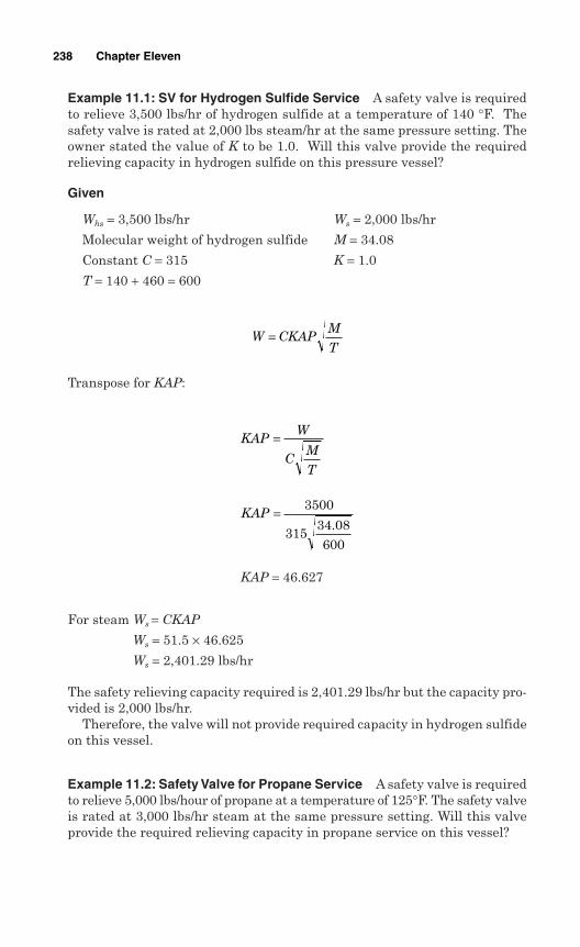
Example 11.1: SV for Hydrogen Sulfide Service A safety valve is requiredto relieve 3,500 lbs/hr of hydrogen sulfide at a temperature of 140 °F. Thesafety valve is rated at 2,000 lbs steam/hr at the same pressure setting. Theowner stated the value of K to be 1.0. Will this valve provide the requiredrelieving capacity in hydrogen sulfide on this pressure vessel?
Given
Whs = 3,500 lbs/hr Ws = 2,000 lbs/hr
Molecular weight of hydrogen sulfide M = 34.08
Constant C = 315 K = 1.0
T = 140 + 460 = 600
Transpose for KAP:
KAP = 46.627
For steam Ws = CKAP
Ws = 51.5 × 46.625
Ws = 2,401.29 lbs/hr
The safety relieving capacity required is 2,401.29 lbs/hr but the capacity pro-vided is 2,000 lbs/hr.
Therefore, the valve will not provide required capacity in hydrogen sulfideon this vessel.
Example 11.2: Safety Valve for Propane Service A safety valve is requiredto relieve 5,000 lbs/hour of propane at a temperature of 125°F. The safety valveis rated at 3,000 lbs/hr steam at the same pressure setting. Will this valveprovide the required relieving capacity in propane service on this vessel?
KAP = 3500
31534 08600
.
KAPW
CM
T
=
W CKAPM
T=
238 Chapter Eleven
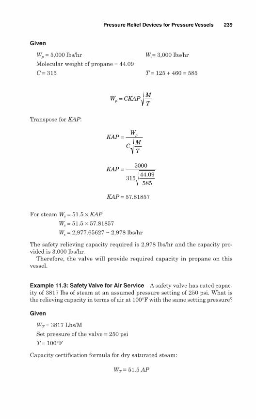
Given
Wp = 5,000 lbs/hr Ws= 3,000 lbs/hr
Molecular weight of propane = 44.09
C = 315 T = 125 + 460 = 585
Transpose for KAP:
KAP = 57.81857
For steam Ws = 51.5 × KAP
Ws = 51.5 × 57.81857
Ws = 2,977.65627 ~ 2,978 lbs/hr
The safety relieving capacity required is 2,978 lbs/hr and the capacity pro-vided is 3,000 lbs/hr.
Therefore, the valve will provide required capacity in propane on thisvessel.
Example 11.3: Safety Valve for Air Service A safety valve has rated capac-ity of 3817 lbs of steam at an assumed pressure setting of 250 psi. What isthe relieving capacity in terms of air at 100°F with the same setting pressure?
Given
WT = 3817 Lbs/M
Set pressure of the valve = 250 psi
T = 100°F
Capacity certification formula for dry saturated steam:
WT = 51.5 AP
KAP = 5000
31544 09585
.
KAPW
CM
T
p=
W CKAPM
Tp =
Pressure Relief Devices for Pressure Vessels 239
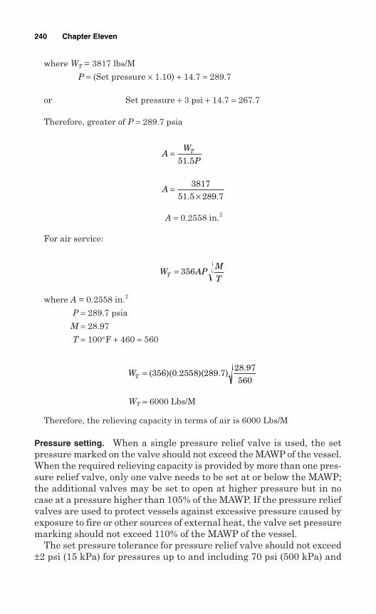
where WT = 3817 lbs/M
P = (Set pressure × 1.10) + 14.7 = 289.7
or Set pressure + 3 psi + 14.7 = 267.7
Therefore, greater of P = 289.7 psia
A = 0.2558 in.2
For air service:
where A = 0.2558 in.2
P = 289.7 psia
M = 28.97
T = 100°F + 460 = 560
WT = 6000 Lbs/M
Therefore, the relieving capacity in terms of air is 6000 Lbs/M
Pressure setting. When a single pressure relief valve is used, the setpressure marked on the valve should not exceed the MAWP of the vessel.When the required relieving capacity is provided by more than one pres-sure relief valve, only one valve needs to be set at or below the MAWP;the additional valves may be set to open at higher pressure but in nocase at a pressure higher than 105% of the MAWP. If the pressure reliefvalves are used to protect vessels against excessive pressure caused byexposure to fire or other sources of external heat, the valve set pressuremarking should not exceed 110% of the MAWP of the vessel.
The set pressure tolerance for pressure relief valve should not exceed±2 psi (15 kPa) for pressures up to and including 70 psi (500 kPa) and
WT = ( )( . )( . ).
356 0 2558 289 728 97560
W APM
TT = 356
A =×
381751 5 289 7. .
AW
PT=
51 5.
240 Chapter Eleven
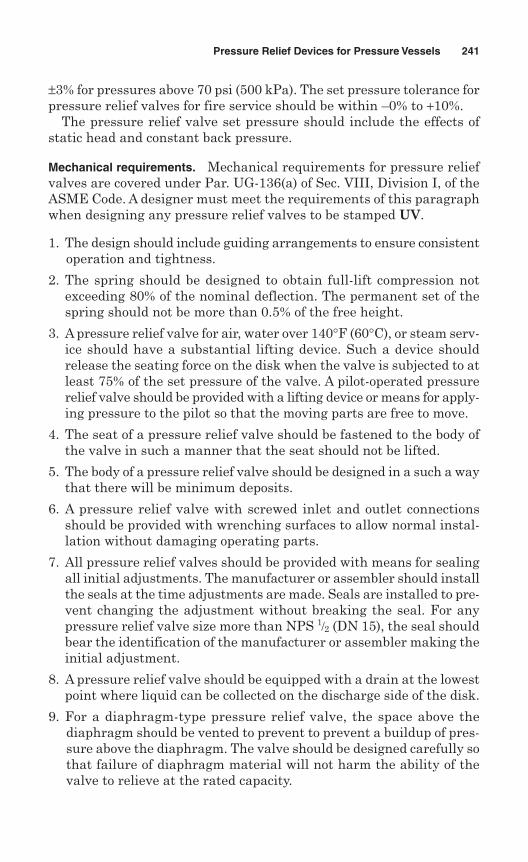
±3% for pressures above 70 psi (500 kPa). The set pressure tolerance forpressure relief valves for fire service should be within –0% to +10%.
The pressure relief valve set pressure should include the effects ofstatic head and constant back pressure.
Mechanical requirements. Mechanical requirements for pressure reliefvalves are covered under Par. UG-136(a) of Sec. VIII, Division I, of theASME Code. A designer must meet the requirements of this paragraphwhen designing any pressure relief valves to be stamped UV.
1. The design should include guiding arrangements to ensure consistentoperation and tightness.
2. The spring should be designed to obtain full-lift compression notexceeding 80% of the nominal deflection. The permanent set of thespring should not be more than 0.5% of the free height.
3. A pressure relief valve for air, water over 140°F (60°C), or steam serv-ice should have a substantial lifting device. Such a device shouldrelease the seating force on the disk when the valve is subjected to atleast 75% of the set pressure of the valve. A pilot-operated pressurerelief valve should be provided with a lifting device or means for apply-ing pressure to the pilot so that the moving parts are free to move.
4. The seat of a pressure relief valve should be fastened to the body ofthe valve in such a manner that the seat should not be lifted.
5. The body of a pressure relief valve should be designed in a such a waythat there will be minimum deposits.
6. A pressure relief valve with screwed inlet and outlet connectionsshould be provided with wrenching surfaces to allow normal instal-lation without damaging operating parts.
7. All pressure relief valves should be provided with means for sealingall initial adjustments. The manufacturer or assembler should installthe seals at the time adjustments are made. Seals are installed to pre-vent changing the adjustment without breaking the seal. For anypressure relief valve size more than NPS 1/2 (DN 15), the seal shouldbear the identification of the manufacturer or assembler making theinitial adjustment.
8. A pressure relief valve should be equipped with a drain at the lowestpoint where liquid can be collected on the discharge side of the disk.
9. For a diaphragm-type pressure relief valve, the space above thediaphragm should be vented to prevent to prevent a buildup of pres-sure above the diaphragm. The valve should be designed carefully sothat failure of diaphragm material will not harm the ability of thevalve to relieve at the rated capacity.
Pressure Relief Devices for Pressure Vessels 241
Materials selection. The materials used in the construction of all pres-sure relief valves must conform to the materials listed in Secs. II andVIII, Division 1, of the ASME Code. Carbon and low-alloy steel bodies,bonnets, yokes, and bolting subject to in-service temperatures lowerthan –20°F (–30°C) should meet the requirements of Par. UCS-66 ofSec. VIII, Division 1. Exception to this paragraph is applicable for mate-rials exempted from impact test and if the materials have a coincidentratio of 0.35 or less.
Materials used for nozzles, disks, and other parts contained withinthe external structure of the pressure relief valve should be one of thefollowing:
Listed in Sec. II Listed in ASTM Specifications Controlled by the manufacturer of the pressure relief valve by a spec-
ification ensuring control of chemical and physical properties andquality at least equivalent to ASTM standards
Cast iron is not permitted to be used in construction of seats and disks.Adjacent sliding surfaces such as guides and disks or disk holders shouldbe of corrosion-resistant material or having a corrosion-resistant coating.The seats and disks should be of materials which can withstand corro-sion of the fluid to be contained.
11.2.4 Capacity certification
A manufacturer of pressure relief valves should have the capacity cer-tified before applying Code symbol UV to any pressure relief valve. Thecapacity should be certified in accordance with Par UG-131 of Sec. VIII,Division 1 of the ASME Code.
Capacity certification of pressure relief valves. Capacity certification testsfor compressible fluids should be conducted on dry saturated steam, air,or gas. If dry saturated steam is used for testing, the limits should be 98%minimum quality and 20°F (10°C) maximum superheat. Correctionwithin these limits may be made to the dry saturated condition. Capacitycertification tests for incompressible fluids should be conducted on waterat a temperature between 40°F (5°C) and 125°F (50°C).
Capacity certification tests should be conducted at a pressure notexceeding the pressure for which the pressure relief valve is set to oper-ate by more than 10% or 3% (20 kPa), whichever is greater. Minimumpressure for capacity certification tests should be at least 3 psi (20 kPa)above set pressure. However, in accordance with Par. UG-131(c)(2),
242 Chapter Eleven
testing may be conducted at a pressure not exceeding 120% of thestamped set pressure of the valve.
Pressure relief valves for compressible fluids having an adjustableblowdown construction should be adjusted prior to testing so that theblowdown does not exceed 5% of the set pressure or 3 psi (20 kPa),whichever is greater.
Capacity certification of pilot-operated pressure relief valves may bebased on tests without the pilot valves installed. The AuthorizedObserver must ensure that the pilot valve opens the main valve fullyat a pressure not exceeding 10% or 3 psi (20 kPa), whichever is greater.
The following methods are used to certify capacity of pressure reliefvalves constructed under ASME Code Sec. VIII, Divisions 1 and 2.
Coefficient method. For steam:
For nozzle W = (51.5APK)
For flat seat W = (51.5p DLPK)
For 45° seat W = (51.5p DLPK)(0.707)
For steam at pressures over 1500 psi and up to 3200 psi, the value of Wof the certified relieving capacity is determined by:
For air:
W = 18.331APK @60°F and 14.7 psia
For gas or vapor:
For liquid (water):
where W = rated capacity, lb/hr (dry saturated steam), scfm (air), lb/hr(gas or vapor), gal/min (water)
A = nozzle throat area, in2
C = constant for gas or vapor based on ratio of specific heats, K = Cp/Cv
D = seat diameter, in
W A w P Pd= −4 814. ( )
W CKAPMT
=
0 1906 10000 2222 1061..
PP
−−
Pressure Relief Devices for Pressure Vessels 243
K = average coefficientL = lift, inM = molecular weightP = (stamped set pressure + 3 psi or 10%, whichever is greater)
+ 14.7, psiaor
P = (stamped set pressure + 20%) + 14.7, psia for test per UG-131(c)(2)
Pd = pressure discharge from valve, psiaT = absolute temperature at inlet, °R (= °F + 460)w = 62.3058 lb/ft3, specific weight of water @70°F
Slope method. The values of slope given have the units scfm or lb/hr/ psia.
W = slope × [(set pressure + 10%) + 14.7, psia]or
W = slope × [(stamped set pressure + 20%) + 14.7] psia for testper UG-131(c)(2)
For liquid (water):
where F = flow factor
Capacity certification of pressure relief valve in combination with nonreclosingpressure relief devices. Manufacturers of pressure relief valves or rupturedisks may have the capacity certified for each combination of pressure reliefvalve and rupture disk device design. The capacity should be certified inaccordance with Par. UG-132 of Sec. VIII, Division 1, of the ASME Code.
11.2.5 Testing by manufacturers
The manufacturer or assembler should conduct production tests foreach pressure relief valve to which a Code symbol stamp is to be applied.A manufacturer or assembler must have a written program for theapplication, calibration, and maintenance of gauges and instrumentsused for the tests.
Pressure test. The primary parts for each pressure relief valve exceed-ing NPS 1 (DN 25) inlet size or 300 psi (2100 MPa) set pressure shouldbe tested at a pressure of a minimum of 1.5 times the design pressure.This test is conducted after completion of all machining operations onthe parts. The test should show no sign of leakage.
W Fx P Pd= −( )
244 Chapter Eleven
The secondary pressure zone of each closed bonnet pressure reliefvalve exceeding NPS 1 (DN 25) inlet size designed for discharge to aclosed system should be tested with air or gas at a pressure of at least30 psi (200 kPa). The test should show no sign of leakage.
Production test. Each pressure relief valve should be tested for poppingpressure. Pressure relief valves for steam service should be tested withsteam, except that valves beyond the capability of the test facility maybe tested on air. Necessary corrections should be established by the man-ufacturer for differentials in popping pressure between steam and air.
Pressure relief valves for gas or vapor may be tested with air. Valvesfor liquid service should be tested with water or other suitable liquid.When a valve is adjusted to correct for service conditions of superim-posed back pressure, temperature, or the differential in popping pres-sure between steam and air, the actual test pressure (cold differentialtest pressure) should be marked on the valve per UG-129.
Seat tightness test. After completion of the popping or set pressure tests,a seat tightness test should be conducted. The seat tightness test andacceptance criteria should be in accordance with API 527. The manu-facturer’s seat tightness procedures are also acceptable if such proce-dures are agreed to by the user.
11.2.6 Inspection and certification
A manufacturer is required to demonstrate to the satisfaction of a repre-sentative of an ASME-designated organization that its manufacturing, pro-duction, testing facilities, and quality control procedures of pressure reliefdevices ensure close agreement between the performance of productionsamples and performance of those submitted for capacity certification.
Inspection. A representative from an ASME -designated organizationmay inspect manufacturing and/ or assembly, inspection, and test oper-ations, including capacity, at any time. The manufacturer’s QualityControl System should include references to the ASME designatedorganization. A current copy of the written Quality Control Systemshould make available to a representative from an ASME designatedorganization,
The Quality Control System should provide a representative from anASME designated organization to have access to all drawings, calcula-tions, specifications, procedures, process sheets, repair procedures,records, test results, and other documents as necessary for the ASMEdesigned or a representative from an ASME designated organization to
Pressure Relief Devices for Pressure Vessels 245
perform his duties according to the Code. The manufacturer should pro-vide such access either to his own documents or provide copies to theASME designee.
Marking. The manufacturer or assembler should mark each pressurerelief valve NPS 1/2 (DN 15) and larger with the data as required byPar. UG-129 of Sec. VIII, Division 1. The data should be marked in sucha way that the marking will not be wiped out in service over a period oftime.
Marking on pressure relief valve. The following markings may be placedon the valve or on a plate to be attached to the pressure relief valve:
1. The name, or an acceptable abbreviation, of the manufacturer and theassembler
2. Manufacturer’s design or type number
3. NPS size _____________ (the nominal pipe size of the valve inlet)
4. Set pressure __________ psi (kPa) and, if applicable, cold differentialtest pressure __________ psi (kPa)
5. Certified capacity (as applicable)
6. Year built, or alternatively, a coding identifying the year the valve wasassembled or tested
7. ASME Code symbol as shown in Fig. 11.8.
Notes
1. Certified capacity for pressure relief valves should be decided accord-ing to the following information:(a) lb/hr of saturated steam at an overpressure of 10% or 3 psi (20 kPa),
whichever is greater.(b) gal/min of water at 70°F (20°C) at an overpressure of 10% or 3 psi
(20 kPa), whichever is greater for valves certified on water.
246 Chapter Eleven
Figure 11.8 ASMECode symbol forpressure relief valve.
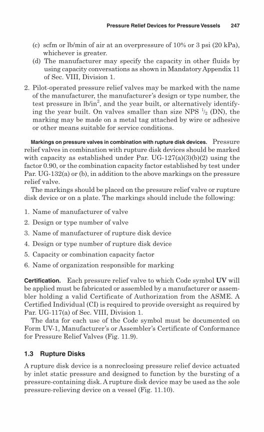
(c) scfm or lb/min of air at an overpressure of 10% or 3 psi (20 kPa),whichever is greater.
(d) The manufacturer may specify the capacity in other fluids byusing capacity conversations as shown in Mandatory Appendix 11of Sec. VIII, Division 1.
2. Pilot-operated pressure relief valves may be marked with the nameof the manufacturer, the manufacturer’s design or type number, thetest pressure in lb/in2, and the year built, or alternatively identify-ing the year built. On valves smaller than size NPS 1/2 (DN), themarking may be made on a metal tag attached by wire or adhesiveor other means suitable for service conditions.
Markings on pressure valves in combination with rupture disk devices. Pressurerelief valves in combination with rupture disk devices should be markedwith capacity as established under Par. UG-127(a)(3)(b)(2) using thefactor 0.90, or the combination capacity factor established by test underPar. UG-132(a) or (b), in addition to the above markings on the pressurerelief valve.
The markings should be placed on the pressure relief valve or rupturedisk device or on a plate. The markings should include the following:
1. Name of manufacturer of valve
2. Design or type number of valve
3. Name of manufacturer of rupture disk device
4. Design or type number of rupture disk device
5. Capacity or combination capacity factor
6. Name of organization responsible for marking
Certification. Each pressure relief valve to which Code symbol UV willbe applied must be fabricated or assembled by a manufacturer or assem-bler holding a valid Certificate of Authorization from the ASME. ACertified Individual (CI) is required to provide oversight as required byPar. UG-117(a) of Sec. VIII, Division 1.
The data for each use of the Code symbol must be documented onForm UV-1, Manufacturer’s or Assembler’s Certificate of Conformancefor Pressure Relief Valves (Fig. 11.9).
1.3 Rupture Disks
A rupture disk device is a nonreclosing pressure relief device actuatedby inlet static pressure and designed to function by the bursting of apressure-containing disk. A rupture disk device may be used as the solepressure-relieving device on a vessel (Fig. 11.10).
Pressure Relief Devices for Pressure Vessels 247
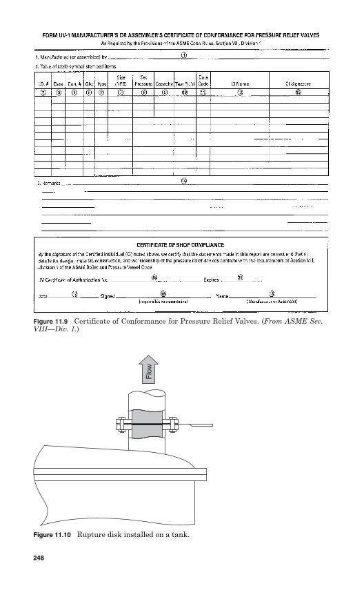
Figure 11.9 Certificate of Conformance for Pressure Relief Valves. (From ASME Sec.VIII––Div. 1.)
Figure 11.10 Rupture disk installed on a tank.
Flo
w
248
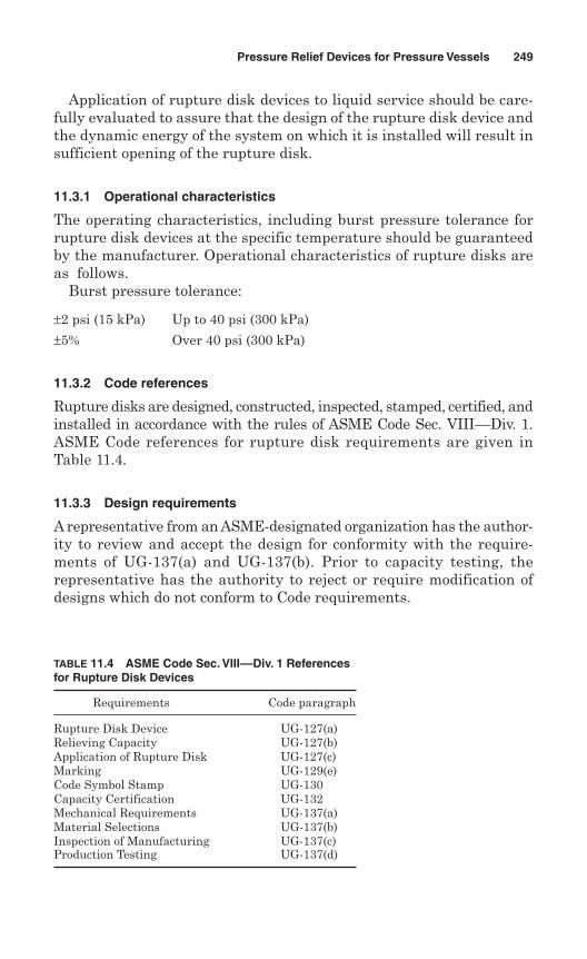
Application of rupture disk devices to liquid service should be care-fully evaluated to assure that the design of the rupture disk device andthe dynamic energy of the system on which it is installed will result insufficient opening of the rupture disk.
11.3.1 Operational characteristics
The operating characteristics, including burst pressure tolerance forrupture disk devices at the specific temperature should be guaranteedby the manufacturer. Operational characteristics of rupture disks areas follows.
Burst pressure tolerance:
±2 psi (15 kPa) Up to 40 psi (300 kPa)
±5% Over 40 psi (300 kPa)
11.3.2 Code references
Rupture disks are designed, constructed, inspected, stamped, certified, andinstalled in accordance with the rules of ASME Code Sec. VIII––Div. 1.ASME Code references for rupture disk requirements are given inTable 11.4.
11.3.3 Design requirements
A representative from an ASME-designated organization has the author-ity to review and accept the design for conformity with the require-ments of UG-137(a) and UG-137(b). Prior to capacity testing, therepresentative has the authority to reject or require modification ofdesigns which do not conform to Code requirements.
Pressure Relief Devices for Pressure Vessels 249
TABLE 11.4 ASME Code Sec. VIII––Div. 1 Referencesfor Rupture Disk Devices
Requirements Code paragraph
Rupture Disk Device UG-127(a)Relieving Capacity UG-127(b)Application of Rupture Disk UG-127(c)Marking UG-129(e)Code Symbol Stamp UG-130Capacity Certification UG-132Mechanical Requirements UG-137(a)Material Selections UG-137(b)Inspection of Manufacturing UG-137(c)Production Testing UG-137(d)
11.3.4 Capacity certification
For capacity certification of a rupture disk, the flow resistance KR hasto be determined. The certified flow resistance KR of the rupture diskdevice should be either KR = 2.4, or determined according to UG-131(k)through UG-131(r) rules as follows.
Flow resistance certification tests for rupture disks for air or gas serv-ice, KRG, should be burst and flow tested with air or gas. Flow resistancetests for liquid service, KRL, should be burst tested with water and flowtested with air or gas. At least one rupture disk for each size of eachseries should be burst with water and flow tested with air or gas todemonstrate the liquid service flow resistance. Flow resistance certifi-cation tests should be conducted at a rupture disk device inlet pressurewhich does not exceed 110% of the device set pressure.
Flow resistance certification of rupture disk devices should be deter-mined by one of the following methods.
One-size method. For each design, three rupture disks from the samelot should be individually burst and flow tested. The burst pressureshould be the minimum of the rupture disk design of the size tested. Thecertified flow resistance KR determined (see procedures below) should beapplied only to the rupture disk design tested.
Three-size method. The three-size method of flow resistance certifica-tion may be used for a rupture disk device design of three or more sizes.The burst pressure should be the minimum of the rupture disk designfor each of the sizes tested.
For each design, three rupture disks from the same lot should beburst and flow tested for each of three different sizes of the same design.The certified flow resistance KR should be applied to all sizes and pres-sures of the design of the rupture disk tested.
A certified flow resistance KR may be established for a specific rup-ture disk design according to the following procedures:
For each design, the manufacturer submits for test the required diskwith cross-section drawings showing the disk design.
Tests are made on each rupture disk to determine burst pressure andflow resistance at an approved testing facility.
An average flow resistance is calculated using the individual flowresistances determined above.
All individual flow resistances should fall within the average flowresistances by an acceptance band of plus or minus three times theaverage of the absolute values of the derivations of the individualflow resistances from the average flow resistance. Any individual flow
250 Chapter Eleven
resistance that falls outside this band should be replaced on a two-for-one basis. A new average should be computed and the individual flowresistances evaluated as described above.
The certified flow resistance KR for a rupture disk design should notbe less than zero. Also, KR should not be less than the sum of theaverage flow resistance plus three times the average of the absolutevalues of the derivations of individual flow resistances from the aver-age flow resistance.
Flow resistance test data reports for each rupture disk design, signedby the manufacturer and the Authorized Observer witnessing thetests, should be submitted to an ASME-designated organization forreview and approval.
New tests should be performed when changes are made to the designof a rupture disk which affect the flow path or burst performancecharacteristics of the device.
11.3.5 Testing by manufacturers
The manufacturer should conduct production tests for each rupturedisk to which a Code symbol stamp is to be applied. A manufacturer musthave a written program for the application, calibration, and mainte-nance of gauges and instrumentation used for the tests.
Pressure test. The pressure parts for each rupture disk holder exceed-ing NPS 1 (DN 25) inlet size or 300 psi (2100 kPa) design pressureshould be tested at a pressure of a minimum of 1.5 times the design pres-sure of the parts. This test is conducted after completion of all machin-ing operations on the parts but prior to installation of the rupture disk.The test should show no sign of leakage.
Production test. Each lot of rupture disks should be tested in accor-dance with Par. UG-137(d)(3). All tests for a given lot should be madein a holder of the same form and pressure area dimensions as that usedin service. Sample rupture disks, selected from each lot, should be madefrom the same material and of the same size as those used in service.
At least two sample rupture disks from each lot of rupture disksshould be burst at the specific disk temperature. Make sure thatsample rupture disk marked burst pressures are within the burstpressure tolerance specified by UG-127(a)(1).
At least four sample rupture disks, but not less than 5% from each lotof rupture disks, should be burst at four different temperatures overthe temperature range for which disk will be used. These data are
Pressure Relief Devices for Pressure Vessels 251
used to establish a smooth curve of burst pressure versus temperaturefor the lot of disks. The value of the marked burst pressure is derivedfrom the curve for a specified temperature.
For prebulged solid metal disks or graphite disks, at least four sam-ples using one size of disk from each lot of material should be burstat four different temperatures distributed over the application range.These data are used to establish a smooth curve of percent change ofburst pressure versus temperature for the lot of material.
At least two disks from each lot of disks, constructed from this lot ofmaterial and of the same size as that to be used, should be burst atthe ambient temperature to establish room-temperature rating of thelot of disks.
11.3.6 Inspection and certification
A manufacturer is required to demonstrate to the satisfaction of a rep-resentative of an ASME-designated organization that its manufacturing,production, testing facilities, and quality control procedures of rupturedisks ensure close agreement between the performance of productionsamples and performance of those submitted for capacity certification.
Inspection. An ASME designee is authorized to inspect manufactur-ing, assembly, inspection, and test operations at any time. A manufac-turer is granted permission by the ASME to use the Code symbol UDon rupture disks in accordance with Par. UG-131. This permissionexpires on the fifth anniversary of the date it was initially granted bythe ASME. The permission may be extended for another 5-year periodif the following tests are successfully performed within the 6-monthperiod before expiration:
Two production samples of rupture disks of a size and capacity withinthe capability of an ASME-approved laboratory are selected by a rep-resentative of an ASME-designated organization.
Burst and flow testing are conducted in the presence of a represen-tative of an ASME-designated organization at an approved testingfacility. The disk manufacturer should be notified of the time of thetest and may have representatives present to witness the test.
If any rupture disk fails to meet the performance requirements (burstpressure, minimum net flow area, and flow resistance), the test shouldbe repeated at the rate of two replacement disks, selected and testedin accordance with above steps.
If any rupture disk fails to meet the performance requirements, thatdisk will be cause for revocation within 60 days of the authorization to
252 Chapter Eleven
use the Code symbol. The manufacturer is required to demonstratethe cause of deficiency and action taken to correct the problem forfuture occurrence.
Marking. The manufacturer or assembler should mark each rupturedisk with the data required by Par. UG-129(e) of Sec. VIII, Division 1,of the ASME Code. The data should be marked in such a way that themarking will not be wiped out in service over a period of time.
The rupture disk marking may be placed on the flange of the disk oron a metal tab in accordance with Par. UG-119. The marking shouldinclude the following:
1. The name or identifying trademark of the manufacturer
2. Manufacturer’s design or type number
3. Lot number
4. Disk material
5. Size _____________[NPS (DN) of rupture disk holder]
6. Marked burst pressure _______________ psi (kPa)
7. Specified disk temperature ___________°F (°C)
8. Minimum net flow area ______________in2 (mm2)
9. Certified flow resistance (as applicable):(a) KRG _____________ for rupture disk certified on air or gases; or(b) KRL _____________ for rupture disk certified on liquid; or(c) KRGL ____________ for rupture disk certified on air or gases, and
liquid10. ASME Code symbol as shown in Fig. 11.11.
11. Year built, or alternatively, a coding may be marked on the rupturedisk so that the disk manufacturer can identify the year the disk wasassembled and tested.
Pressure Relief Devices for Pressure Vessels 253
Figure 11.11 ASMECode symbol forrupture disk.
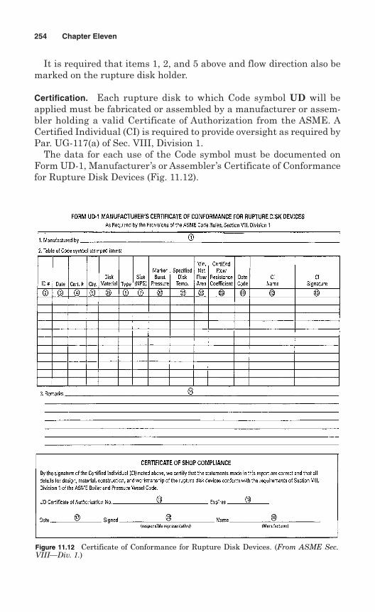
It is required that items 1, 2, and 5 above and flow direction also bemarked on the rupture disk holder.
Certification. Each rupture disk to which Code symbol UD will beapplied must be fabricated or assembled by a manufacturer or assem-bler holding a valid Certificate of Authorization from the ASME. ACertified Individual (CI) is required to provide oversight as required byPar. UG-117(a) of Sec. VIII, Division 1.
The data for each use of the Code symbol must be documented onForm UD-1, Manufacturer’s or Assembler’s Certificate of Conformancefor Rupture Disk Devices (Fig. 11.12).
254 Chapter Eleven
Figure 11.12 Certificate of Conformance for Rupture Disk Devices. (From ASME Sec.VIII––Div. 1.)
Chapter
Pressure Relief Devicesfor Nuclear Systems
The world’s first nuclear power plant was started-up in 1956 atCalder Hall in England, followed in the United States a year later bythe initial operation of a 60-MW unit at Shippingport, Pennsylvania.Power production with nuclear energy relies on a sustained neutronchain reaction from the fusion process. Reactors produce electricityfrom fission, employing a variety of fuel forms, coolants, and othermaterials.
Nuclear power reactors are complex systems whose design represents abalance among various system requirements. Principal among theserequirements are nuclear design, materials, economics, thermal hydraulics,and control and safety. The following ASME codes are used for design, con-struction, inspection, stamping, and certification of nuclear components:
Section III, Subsec. NCA—General Requirements for Division 1 andDivision 2
Section III, Division 1:Subsec. NB—Class 1 ComponentsSubsec. NC—Class 2 ComponentsSubsec. ND—Class 3 ComponentsSubsec. NE—Class MC ComponentsSubsec. NF—SupportsSubsec. NG—Core Support SystemsSubsec. NH—Class 1 Components in Elevated Temperature ServiceAppendices
Section III, Division 2—Code for Concrete Reactor Vessels andContainments
255
12
Copyright © 2006 by The McGraw-Hill Companies, Inc. Click here for terms of use.
Section III, Division 3—Containment Systems for Storage andTransport Packagings of Spent Nuclear Fuel and High LevelRadioactive Material and Waste
Nuclear systems (the nuclear symbol is shown in Fig. 12.1) are pro-tected from the consequences arising from the applications of conditionsof pressure and coincident temperature that would cause either thedesign pressure or the service limits specified in the design specifica-tion to be exceeded. Pressure relief devices are used when the operat-ing conditions considered in the Overpressure Protection Report wouldcause the service limits specified in the design specification to beexceeded.
The overpressure protection of nuclear systems must meet therequirements of Art. NB-7000 of ASME Code Sec. III, Division I,Subsec. NB.
12.1 Nuclear Reactors
A nuclear reactor—the heart of a nuclear steam supply system, whichencompasses all components related to the use of nuclear fission as theenergy source—is designed to achieve a self-sustained chain reactionwith a combination of fissile, fertile, and other materials. Six majorreactor types are used throughout the world:
256 Chapter Twelve
Figure 12.1 Symbol for nuclear systems.
1. Boiling-water reactor (BWR)
2. Pressurized-water reactor (PWR)
3. Heavy-water-moderated reactor (HWR), including the pressureheavy-water reactor (PHWR)
4. Light-water-cooled graphite-moderated reactor (LGR), including thepressure-tube graphite reactor (PTGR)
5. Gas-cooled reactor (GCR), including the high-temperature gas-cooledreactor (HTGR)
6. Breeder reactor, including the liquid-metal fast breeder reactor(LMFBR)
The two most popular reactor designs employ light water as bothcoolant and moderator. These two light-water reactor systems—theboiling-water reactor (BWR) and the pressurized-water reactor (PWR)—use ordinary (“light”) water as both coolant and moderator. The BWRproduces steam through a direct cycle, while the PWR uses an inter-mediate steam-generator heat exchanger to maintain an all-liquidprimary loop and produce steam in a secondary loop. Our discussion ofnuclear reactors will be limited to these two types of reactors.
12.1.1 Boiling-water reactors
Boiling water reactors were originally designed by Allis-Chambers andGeneral Electric (GE). The GE design has survived, whereas all Allis-Chambers units have been shut down.
The BWR typically permits bulk boiling of water in the reactor. Theoperating temperature of the reactor is approximately 570°F, producingsteam at a pressure of 1000 psig. Current BWRs have electrical outputsof 570–1300 MWe. A flow diagram of a BWR system is shown in Fig. 12.2.
In Fig. 12.2, water is circulated through the reactor core, picking upheat as the water moves past the fuel assemblies. The water is heatedenough to convert to steam. Steam separators in the upper part of thereactor remove water from the steam. Then the steam passes throughthe main steam lines to the turbogenerators.
The steam, after passing through the turbines, then condenses in thecondenser, which is at vacuum and is cooled by water. The condensedsteam then is pumped to low-pressure feedwater heaters. The waterthen passes to feedwater pumps, which in turn pump the water to thereactor and start the cycle all over again.
Safety valves for main steam line. Safety valves are required on the mainsteam lines (Fig. 12.3) to protect the steam generator from overpressure.A safety valve used as a main steam valve is shown in Fig. 12.4.
Pressure Relief Devices for Nuclear Systems 257
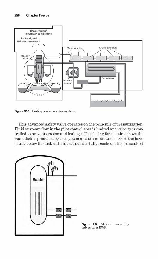
This advanced safety valve operates on the principle of pressurization.Fluid or steam flow in the pilot control area is limited and velocity is con-trolled to prevent erosion and leakage. The closing force acting above themain disk is produced by the system and is a minimum of twice the forceacting below the disk until lift set point is fully reached. This principle of
258 Chapter Twelve
Torus
Control rods
Reactorcore
Inerted drywell(primary containment)
Reactor building(secondary containment)
Feedwaterpumps
Condenser
Main steam lines Turbine generators
Figure 12.2 Boiling-water reactor system.
Figure 12.3 Main steam safetyvalves on a BWR.
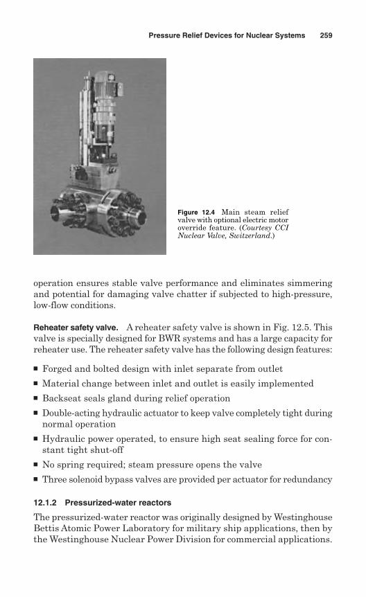
operation ensures stable valve performance and eliminates simmeringand potential for damaging valve chatter if subjected to high-pressure,low-flow conditions.
Reheater safety valve. A reheater safety valve is shown in Fig. 12.5. Thisvalve is specially designed for BWR systems and has a large capacity forreheater use. The reheater safety valve has the following design features:
Forged and bolted design with inlet separate from outlet Material change between inlet and outlet is easily implemented Backseat seals gland during relief operation Double-acting hydraulic actuator to keep valve completely tight during
normal operation Hydraulic power operated, to ensure high seat sealing force for con-
stant tight shut-off No spring required; steam pressure opens the valve Three solenoid bypass valves are provided per actuator for redundancy
12.1.2 Pressurized-water reactors
The pressurized-water reactor was originally designed by WestinghouseBettis Atomic Power Laboratory for military ship applications, then bythe Westinghouse Nuclear Power Division for commercial applications.
Pressure Relief Devices for Nuclear Systems 259
Figure 12.4 Main steam reliefvalve with optional electric motoroverride feature. (Courtesy CCINuclear Valve, Switzerland.)
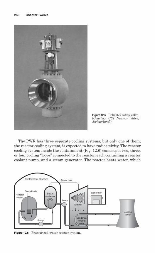
The PWR has three separate cooling systems, but only one of them,the reactor cooling system, is expected to have radioactivity. The reactorcooling system inside the containment (Fig. 12.6) consists of two, three,or four cooling “loops” connected to the reactor, each containing a reactorcoolant pump, and a steam generator. The reactor heats water, which
260 Chapter Twelve
Figure 12.5 Reheater safety valve.(Courtesy CCI Nuclear Valve,Switzerland.)
Control rods
Coolingtower
Generator
Turbine
Condensorcoolingwater
Pump
Pump
Steamcondensor
Reactorvessel
Containment structure Steam line
Figure 12.6 Pressurized-water reactor system.
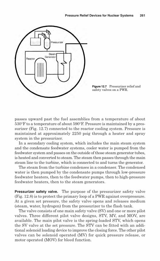
passes upward past the fuel assemblies from a temperature of about530°F to a temperature of about 590°F. Pressure is maintained by a pres-surizer (Fig. 12.7) connected to the reactor cooling system. Pressure ismaintained at approximately 2250 psig through a heater and spraysystem in the pressurizer.
In a secondary cooling system, which includes the main steam systemand the condensate feedwater systems, cooler water is pumped from thefeedwater system and passes on the outside of those steam generator tubes,is heated and converted to steam. The steam then passes through the mainsteam line to the turbine, which is connected to and turns the generator.
The steam from the turbine condenses in a condenser. The condensedwater is then pumped by the condensate pumps through low-pressurefeedwater heaters, then to the feedwater pumps, then to high-pressurefeedwater heaters, then to the steam generators.
Pressurizer safety valve. The purpose of the pressurizer safety valve(Fig. 12.8) is to protect the primary loop of a PWR against overpressure.At a given set pressure, the safety valve opens and releases medium(steam, water, hydrogen) from the pressurizer to the flash tank.
The valve consists of one main safety valve (SV) and one or more pilotvalves. Three different pilot valve designs, STV, MV, and MOV, areavailable. The main pilot valve is the spring-loaded STV, which opensthe SV valve at the set pressure. The STV can be fitted with an addi-tional solenoid loading device to improve the closing force. The other pilotvalves can be solenoid operated (MV) for quick pressure release, ormotor operated (MOV) for bleed function.
Pressure Relief Devices for Nuclear Systems 261
Figure 12.7 Pressurizer relief andsafety valves on a PWR.
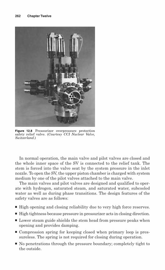
In normal operation, the main valve and pilot valves are closed andthe whole inner space of the SV is connected to the relief tank. Thestem is forced into the valve seat by the system pressure in the inletnozzle. To open the SV, the upper piston chamber is charged with systemmedium by one of the pilot valves attached to the main valve.
The main valves and pilot valves are designed and qualified to oper-ate with hydrogen, saturated steam, and saturated water, subcooledwater as well as during phase transitions. The design features of thesafety valves are as follows:
High opening and closing reliability due to very high force reserves. High tightness because pressure in pressurizer acts in closing direction. Lower steam guide shields the stem head from pressure peaks when
opening and provides damping. Compression spring for keeping closed when primary loop is pres-
sureless. The spring is not required for closing during operation. No penetrations through the pressure boundary; completely tight to
the outside.
262 Chapter Twelve
Figure 12.8 Pressurizer overpressure protectionsafety relief valve. (Courtesy CCI Nuclear Valve,Switzerland.)
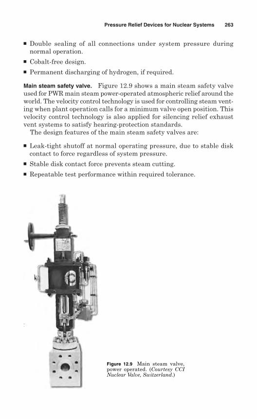
Double sealing of all connections under system pressure duringnormal operation.
Cobalt-free design. Permanent discharging of hydrogen, if required.
Main steam safety valve. Figure 12.9 shows a main steam safety valveused for PWR main steam power-operated atmospheric relief around theworld. The velocity control technology is used for controlling steam vent-ing when plant operation calls for a minimum valve open position. Thisvelocity control technology is also applied for silencing relief exhaustvent systems to satisfy hearing-protection standards.
The design features of the main steam safety valves are:
Leak-tight shutoff at normal operating pressure, due to stable diskcontact to force regardless of system pressure.
Stable disk contact force prevents steam cutting. Repeatable test performance within required tolerance.
Pressure Relief Devices for Nuclear Systems 263
Figure 12.9 Main steam valve,power operated. (Courtesy CCINuclear Valve, Switzerland.)
12.2 Overpressure Protection Reports
Par. NB-7111 of Sec. III – Div. 1 defines overpressure as “that pressurewhich exceeds the Design Pressure and is caused by increase in systemfluid pressure resulting from thermal imbalances, excess pump flow, andother similar phenomena capable of causing a system pressure increaseof a sufficient duration to be compatible with the dynamic responsecharacteristics of the pressure relief devices.”
An Overpressure Protection Report (OPR) is a report on the protectedsystems and integrated overpressure provided. The owner or his designeeprepares the Overpressure Protection Report I. In accordance withPar. NB-7120, overpressure protection of the components must be providedby any one of the following as an integrated overpressure protection:
1. The use of pressure relief devices and associated pressure sensingelements
2. The use of reactor shutdown system
3. A design without pressure relief devices that does not exceed theservice limits specified in the design specification
12.2.1 Content of report
The Overpressure Protection Report should clearly define the protectedsystems and integrated overpressure protection. The report shouldincluding the following as a minimum:
1. Identification of ASME Nuclear Code Section, Edition, Addenda, andCode Cases used in the design of the overpressure protection system.
2. Drawings indicating arrangement of protected system including thepressure relief devices
3. The operating conditions, including discharge piping back pressure
4. An analysis of the conditions that give rise to the maximum pressure-relieving requirements
5. The relief capacity required to prevent a pressure rise in any nuclearcomponent from exceeding by the design pressure more than 10%
6. The operating controls and safety controls of the protected system
7. The redundancy and independence of the pressure relief devices topreclude a loss of overpressure protection in the event of a failureof any pressure relief device, sensing elements, associated controls,or external power sources
8. The extent to which a component can be isolated from the overallsystem and analysis of the conditions under which additional indi-vidual overpressure protection is required
264 Chapter Twelve
9. The design secondary pressure, which is defined as that value ofpressure existing in the passage between the actual discharge areaand the outlet for which the discharge system of the pressure reliefvalve is designed
10. Analysis of transient pressure conditions, considering the effect ofliquid and two-phase flow
11. Consideration of set pressure and blowdown limitations, taking intoaccount opening pressure tolerances and overpressure
12. Consideration of burst pressure tolerance and manufacturing designof rupture disk devices
13. Verification that pressure relief devices are not required, if necessary
14. The purge time of the inlet water seal, if the pressure relief valveis installed on a loop seal
12.2.2 Certification of report
The OPR should meet the requirements of Art. NB-700 of ASME Sec. III,Division I: A Registered Professional Engineer competent in the appli-cable field of design must certify the report on Form A-3, OverpressureProtection Report (Fig. 12.10), after it has been verified against theCode requirements. The Registered Professional Engineer must be qual-ified in accordance with the requirements of Mandatory App. XXXIIIof the Section.
12.2.3 Review of report
The Overpressure Protection Report requires a review if any modifica-tion is done during installation. The modification is required to be rec-onciled with the Overpressure Protection Report. Such modificationsshould be documented in an addendum to the Overpressure ProtectionReport. The addendum should contain a copy of the as-built drawing andinclude one of the following items:
1. A statement that the as-built system has met the requirements of theOPR
2. A revision to the OPR to make it agree with the as-built system
3. A description of changes made to the as-built system to make itcomply with the OPR
A Registered Professional Engineer competent in the specific field ofdesign should certify the addendum.
Pressure Relief Devices for Nuclear Systems 265
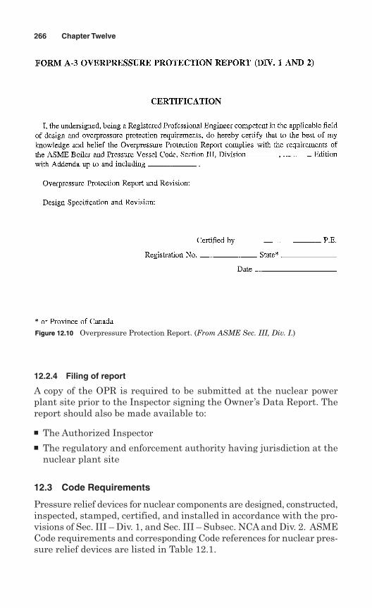
12.2.4 Filing of report
A copy of the OPR is required to be submitted at the nuclear powerplant site prior to the Inspector signing the Owner’s Data Report. Thereport should also be made available to:
The Authorized Inspector The regulatory and enforcement authority having jurisdiction at the
nuclear plant site
12.3 Code Requirements
Pressure relief devices for nuclear components are designed, constructed,inspected, stamped, certified, and installed in accordance with the pro-visions of Sec. III – Div. 1, and Sec. III – Subsec. NCA and Div. 2. ASMECode requirements and corresponding Code references for nuclear pres-sure relief devices are listed in Table 12.1.
266 Chapter Twelve
Figure 12.10 Overpressure Protection Report. (From ASME Sec. III, Div. I.)
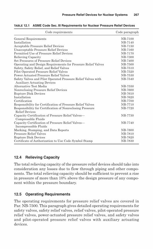
12.4 Relieving Capacity
The total relieving capacity of the pressure relief devices should take intoconsideration any losses due to flow through piping and other compo-nents. The total relieving capacity should be sufficient to prevent a risein pressure of more than 10% above the design pressure of any compo-nent within the pressure boundary.
12.5 Operating Requirements
The operating requirements for pressure relief valves are covered inPar. NB-7500. This paragraph gives detailed operating requirements forsafety valves, safety relief valves, relief valves, pilot-operated pressurerelief valves, power-actuated pressure relief valves, and safety valvesand pilot-operated pressure relief valves with auxiliary actuatingdevices.
Pressure Relief Devices for Nuclear Systems 267
TABLE 12.1 ASME Code Sec. III Requirements for Nuclear Pressure Relief Devices
Code requirements Code paragraph
General Requirements NB-7100Installation NB-7140Acceptable Pressure Relief Devices NB-7150Unacceptable Pressure Relief Devices NB-7160Permitted Use of Pressure Relief Devices NB-7170Relieving Capacity NB-7300Set Pressures of Pressure Relief Devices NB-7400Operating and Design Requirements for Pressure Relief Valves NB-7500Safety, Safety Relief, and Relief Valves NB-7510Pilot Operated Pressure Relief Valves NB-7520Power Actuated Pressure Relief Valves NB-7530Safety Valves and Pilot Operated Pressure Relief Valves with NB-7540Auxiliary Actuating Devices
Alternative Test Media NB-7550Nonreclosing Pressure Relief Devices NB-7600Rupture Disk Devices NB-7610Installation NB-7620Certification NB-7700Responsibility for Certification of Pressure Relief Valves NB-7710Responsibility for Certification of Nonreclosing Pressure NB-7720Relief Devices
Capacity Certification of Pressure Relief Valves— NB-7730Compressible Fluids
Capacity Certification of Pressure Relief Valves— NB-7740Incompressible Fluids
Marking, Stamping, and Data Reports NB-7800Pressure Relief Valves NB-7810Rupture Disk Devices NB-7820Certificate of Authorization to Use Code Symbol Stamp NB-7830
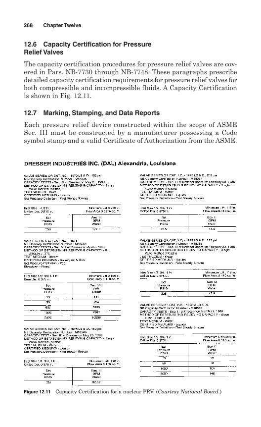
12.6 Capacity Certification for PressureRelief Valves
The capacity certification procedures for pressure relief valves are cov-ered in Pars. NB-7730 through NB-7748. These paragraphs prescribedetailed capacity certification requirements for pressure relief valves forboth compressible and incompressible fluids. A Capacity Certificationis shown in Fig. 12.11.
12.7 Marking, Stamping, and Data Reports
Each pressure relief device constructed within the scope of ASMESec. III must be constructed by a manufacturer possessing a Codesymbol stamp and a valid Certificate of Authorization from the ASME.
268 Chapter Twelve
Figure 12.11 Capacity Certification for a nuclear PRV. (Courtesy National Board.)
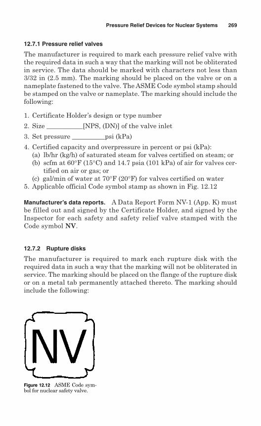
12.7.1 Pressure relief valves
The manufacturer is required to mark each pressure relief valve withthe required data in such a way that the marking will not be obliteratedin service. The data should be marked with characters not less than3/32 in (2.5 mm). The marking should be placed on the valve or on anameplate fastened to the valve. The ASME Code symbol stamp shouldbe stamped on the valve or nameplate. The marking should include thefollowing:
1. Certificate Holder’s design or type number
2. Size ___________[NPS, (DN)] of the valve inlet
3. Set pressure __________psi (kPa)
4. Certified capacity and overpressure in percent or psi (kPa):(a) lb/hr (kg/h) of saturated steam for valves certified on steam; or(b) scfm at 60°F (15°C) and 14.7 psia (101 kPa) of air for valves cer-
tified on air or gas; or(c) gal/min of water at 70°F (20°F) for valves certified on water
5. Applicable official Code symbol stamp as shown in Fig. 12.12
Manufacturer’s data reports. A Data Report Form NV-1 (App. K) mustbe filled out and signed by the Certificate Holder, and signed by theInspector for each safety and safety relief valve stamped with theCode symbol NV.
12.7.2 Rupture disks
The manufacturer is required to mark each rupture disk with therequired data in such a way that the marking will not be obliterated inservice. The marking should be placed on the flange of the rupture diskor on a metal tab permanently attached thereto. The marking shouldinclude the following:
Pressure Relief Devices for Nuclear Systems 269
Figure 12.12 ASME Code sym-bol for nuclear safety valve.
1. Manufacturer’s design or type number
2. Lot number
3. Size ___________ NPS (DN)
4. Stamped burst pressure __________psi (kPa)
5. Specified disk temperature ____________°F (°C)
6. Capacity ______lb/hr (kg/h) of saturated steam or scfm of air at 60°F(15°C) and 14.7 psia/min (101 kPa/min)
7. Year built
Disk holders. Rupture disk holders should be marked with the follow-ing data:
1. The name or identifying trademark of the manufacturer
2. Manufacturer’s design or type number
3. Size ______________ NPS (DN)
4. Year built
5. Serial number
270 Chapter Twelve
Chapter
Pressure Relief Devices for Transport Tanks
Transport tanks are used to carry dangerous goods via highway, rail, air,or water. A tank consists of a pressure vessel, service equipment, andexternal structural components. The ASME Code, Sec. XII—Rules forConstruction and Continued Service of Transport Tanks, is applicablefor construction and continued service of transport tanks. This Code wasfirst published on July 1, 2004.
The term pressure vessel refers to the pressure boundary defined bythe geometric shape, but not limited to, the shell, heads, and openings.Construction of a pressure vessel includes materials, design, fabrica-tion, examination, shop inspection, testing, certifications, and over pres-sure protection. The term continued service means inspection, testing,repair, alteration, and recertification of a transport tank that has beenin service.
The rules of ASME Sec. XII are applicable to pressure vessels intendedfor transporting dangerous goods with design pressures appropriate forthe transportation mode and volumes greater than 450 L (120 gal). Thephysical scope of the pressure vessel is as follows:
Internal pressure should be in the range from 0 to 270 bar (fullvacuum to 3000 psig).
The temperature range should be from –269 to 343°C (–452 to 650°F). Thickness of the shell and heads should not exceed 38 mm (11/2 in).
The laws and regulations of transport tanks intended for the trans-portation of dangerous goods are enforced by the Competent Authority,which is the federal government at this time. The Code of Federal
271
13
Copyright © 2006 by The McGraw-Hill Companies, Inc. Click here for terms of use.
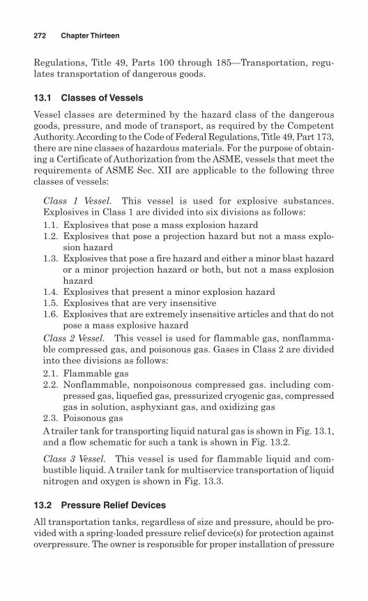
Regulations, Title 49, Parts 100 through 185—Transportation, regu-lates transportation of dangerous goods.
13.1 Classes of Vessels
Vessel classes are determined by the hazard class of the dangerousgoods, pressure, and mode of transport, as required by the CompetentAuthority. According to the Code of Federal Regulations, Title 49, Part 173,there are nine classes of hazardous materials. For the purpose of obtain-ing a Certificate of Authorization from the ASME, vessels that meet therequirements of ASME Sec. XII are applicable to the following threeclasses of vessels:
Class 1 Vessel. This vessel is used for explosive substances.Explosives in Class 1 are divided into six divisions as follows:1.1. Explosives that pose a mass explosion hazard1.2. Explosives that pose a projection hazard but not a mass explo-
sion hazard1.3. Explosives that pose a fire hazard and either a minor blast hazard
or a minor projection hazard or both, but not a mass explosionhazard
1.4. Explosives that present a minor explosion hazard1.5. Explosives that are very insensitive1.6. Explosives that are extremely insensitive articles and that do not
pose a mass explosive hazardClass 2 Vessel. This vessel is used for flammable gas, nonflamma-ble compressed gas, and poisonous gas. Gases in Class 2 are dividedinto thee divisions as follows:2.1. Flammable gas 2.2. Nonflammable, nonpoisonous compressed gas. including com-
pressed gas, liquefied gas, pressurized cryogenic gas, compressedgas in solution, asphyxiant gas, and oxidizing gas
2.3. Poisonous gasA trailer tank for transporting liquid natural gas is shown in Fig. 13.1,and a flow schematic for such a tank is shown in Fig. 13.2.
Class 3 Vessel. This vessel is used for flammable liquid and com-bustible liquid. A trailer tank for multiservice transportation of liquidnitrogen and oxygen is shown in Fig. 13.3.
13.2 Pressure Relief Devices
All transportation tanks, regardless of size and pressure, should be pro-vided with a spring-loaded pressure relief device(s) for protection againstoverpressure. The owner is responsible for proper installation of pressure
272 Chapter Thirteen
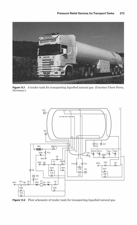
Pressure Relief Devices for Transport Tanks 273
Figure 13.1 A trailer tank for transporting liquefied natural gas. (Courtesy Chart-Ferox,Germany.)
RF1
PI
PILI
V19
SV6
HC1 CV1 M1 V3 VE2 P1S1 VE1 V4
SV9
PI2
V17
V8
HC2 S2
HC4
V12SV8
PB1 AOV4
V5
V1 AOV3
SV3
V18
SV9
LL1
V16 PI1
V14V15
V26
SV7
V22HC3 V9
AOV2
SV10V10
SV11 SV1 SV2
VV1TV1TC1
PI
PI3
Figure 13.2 Flow schematic of trailer tank for transporting liquefied natural gas.
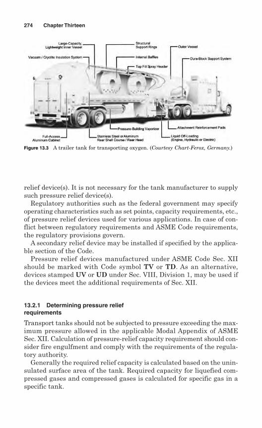
relief device(s). It is not necessary for the tank manufacturer to supplysuch pressure relief device(s).
Regulatory authorities such as the federal government may specifyoperating characteristics such as set points, capacity requirements, etc.,of pressure relief devices used for various applications. In case of con-flict between regulatory requirements and ASME Code requirements,the regulatory provisions govern.
A secondary relief device may be installed if specified by the applica-ble section of the Code.
Pressure relief devices manufactured under ASME Code Sec. XIIshould be marked with Code symbol TV or TD. As an alternative,devices stamped UV or UD under Sec. VIII, Division 1, may be used ifthe devices meet the additional requirements of Sec. XII.
13.2.1 Determining pressure reliefrequirements
Transport tanks should not be subjected to pressure exceeding the max-imum pressure allowed in the applicable Modal Appendix of ASMESec. XII. Calculation of pressure-relief capacity requirement should con-sider fire engulfment and comply with the requirements of the regula-tory authority.
Generally the required relief capacity is calculated based on the unin-sulated surface area of the tank. Required capacity for liquefied com-pressed gases and compressed gases is calculated for specific gas in aspecific tank.
274 Chapter Thirteen
Figure 13.3 A trailer tank for transporting oxygen. (Courtesy Chart-Ferox, Germany.)
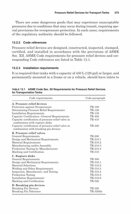
There are some dangerous goods that may experience unacceptablepressures due to conditions that may occur during transit, requiring spe-cial provisions for overpressure protection. In such cases, requirementsof the regulatory authority should be followed.
13.2.2 Code references
Pressure relief devices are designed, constructed, inspected, stamped,certified, and installed in accordance with the provisions of ASMESec. XII. ASME Code requirements for pressure relief devices and cor-responding Code references are listed in Table 13.1.
13.2.3 Installation requirements
It is required that tanks with a capacity of 450 L (120 gal) or larger, andpermanently mounted in a frame or on a vehicle, should have inlets to
Pressure Relief Devices for Transport Tanks 275
TABLE 13.1 ASME Code Sec. XII Requirements for Pressure Relief Devicesfor Transportation Tanks
Code requirements Code paragraph
A. Pressure relief devicesProtection against Overpressure TR-100Determining Pressure Relief Requirements TR-120Installation Requirements TR-130Capacity Certification—General Requirements TR-400Capacity certification of pressure relief valve in TR-410combination with rupture disks
Capacity certification of pressure relief valve in TR-420combination with breaking pin devices
B. Pressure relief valvesGeneral Requirements TR-200Design and Mechanical Requirements TR-210.1Material Requirements TR-210.2Manufacturing and/or Assembly TR-210.3Production Testing by Manufacturers TR-210.4Marking and Certification TR-510
C. Rupture disksGeneral Requirements TR-300Design and Mechanical Requirements TR-310.1Material Selections TR-310.2Welding and Other Requirements TR-310.3Inspection, Manufacture, and Testing TR-310.4Production Testing TR-310.5Installation Requirements TR-310.6Marking and Certification TR-520
D. Breaking pin devicesBreaking Pin Devices TR-320Breaking Pin Tolerance TR-320(b)
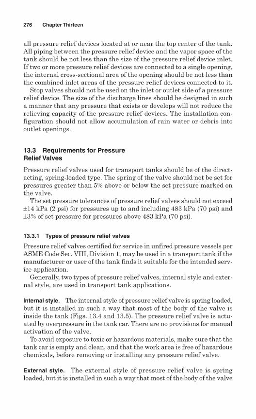
all pressure relief devices located at or near the top center of the tank.All piping between the pressure relief device and the vapor space of thetank should be not less than the size of the pressure relief device inlet.If two or more pressure relief devices are connected to a single opening,the internal cross-sectional area of the opening should be not less thanthe combined inlet areas of the pressure relief devices connected to it.
Stop valves should not be used on the inlet or outlet side of a pressurerelief device. The size of the discharge lines should be designed in sucha manner that any pressure that exists or develops will not reduce therelieving capacity of the pressure relief devices. The installation con-figuration should not allow accumulation of rain water or debris intooutlet openings.
13.3 Requirements for PressureRelief Valves
Pressure relief valves used for transport tanks should be of the direct-acting, spring-loaded type. The spring of the valve should not be set forpressures greater than 5% above or below the set pressure marked onthe valve.
The set pressure tolerances of pressure relief valves should not exceed±14 kPa (2 psi) for pressures up to and including 483 kPa (70 psi) and±3% of set pressure for pressures above 483 kPa (70 psi).
13.3.1 Types of pressure relief valves
Pressure relief valves certified for service in unfired pressure vessels perASME Code Sec. VIII, Division 1, may be used in a transport tank if themanufacturer or user of the tank finds it suitable for the intended serv-ice application.
Generally, two types of pressure relief valves, internal style and exter-nal style, are used in transport tank applications.
Internal style. The internal style of pressure relief valve is spring loaded,but it is installed in such a way that most of the body of the valve isinside the tank (Figs. 13.4 and 13.5). The pressure relief valve is actu-ated by overpressure in the tank car. There are no provisions for manualactivation of the valve.
To avoid exposure to toxic or hazardous materials, make sure that thetank car is empty and clean, and that the work area is free of hazardouschemicals, before removing or installing any pressure relief valve.
External style. The external style of pressure relief valve is springloaded, but it is installed in such a way that most of the body of the valve
276 Chapter Thirteen
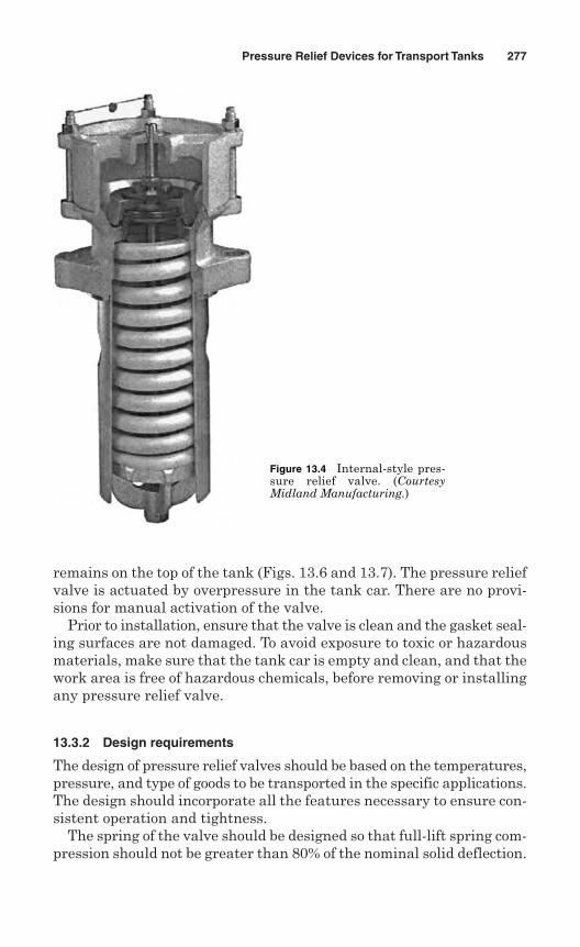
remains on the top of the tank (Figs. 13.6 and 13.7). The pressure reliefvalve is actuated by overpressure in the tank car. There are no provi-sions for manual activation of the valve.
Prior to installation, ensure that the valve is clean and the gasket seal-ing surfaces are not damaged. To avoid exposure to toxic or hazardousmaterials, make sure that the tank car is empty and clean, and that thework area is free of hazardous chemicals, before removing or installingany pressure relief valve.
13.3.2 Design requirements
The design of pressure relief valves should be based on the temperatures,pressure, and type of goods to be transported in the specific applications.The design should incorporate all the features necessary to ensure con-sistent operation and tightness.
The spring of the valve should be designed so that full-lift spring com-pression should not be greater than 80% of the nominal solid deflection.
Pressure Relief Devices for Transport Tanks 277
Figure 13.4 Internal-style pres-sure relief valve. (CourtesyMidland Manufacturing.)
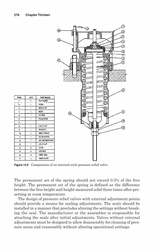
The permanent set of the spring should not exceed 0.5% of the freeheight. The permanent set of the spring is defined as the differencebetween the free height and height measured solid three times after pre-setting at room temperature.
The design of pressure relief valves with external adjustment pointsshould provide a means for sealing adjustments. The seals should beinstalled in a manner that precludes altering the settings without break-ing the seal. The manufacturer or the assembler is responsible forattaching the seals after initial adjustments. Valves without externaladjustments must be designed to allow disassembly for cleaning of pres-sure areas and reassembly without altering operational settings.
278 Chapter Thirteen
Figure 13.5 Components of an internal-style pressure relief valve.
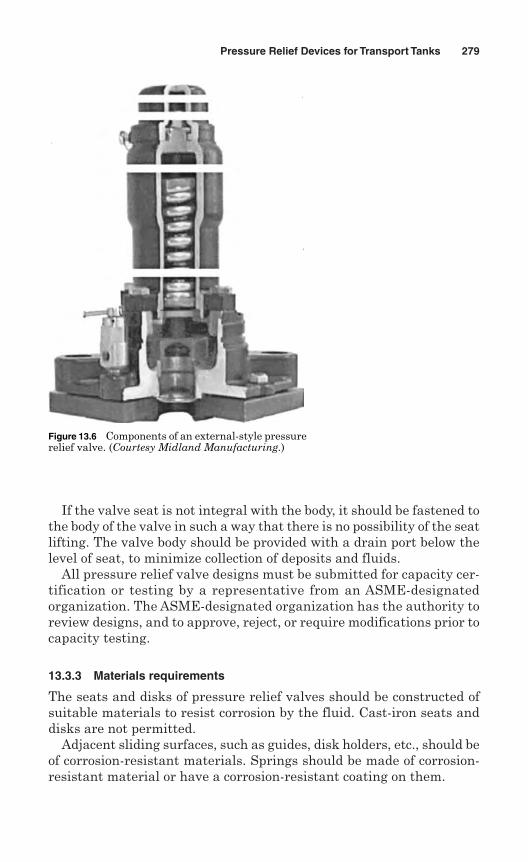
If the valve seat is not integral with the body, it should be fastened tothe body of the valve in such a way that there is no possibility of the seatlifting. The valve body should be provided with a drain port below thelevel of seat, to minimize collection of deposits and fluids.
All pressure relief valve designs must be submitted for capacity cer-tification or testing by a representative from an ASME-designatedorganization. The ASME-designated organization has the authority toreview designs, and to approve, reject, or require modifications prior tocapacity testing.
13.3.3 Materials requirements
The seats and disks of pressure relief valves should be constructed ofsuitable materials to resist corrosion by the fluid. Cast-iron seats anddisks are not permitted.
Adjacent sliding surfaces, such as guides, disk holders, etc., should beof corrosion-resistant materials. Springs should be made of corrosion-resistant material or have a corrosion-resistant coating on them.
Pressure Relief Devices for Transport Tanks 279
Figure 13.6 Components of an external-style pressurerelief valve. (Courtesy Midland Manufacturing.)
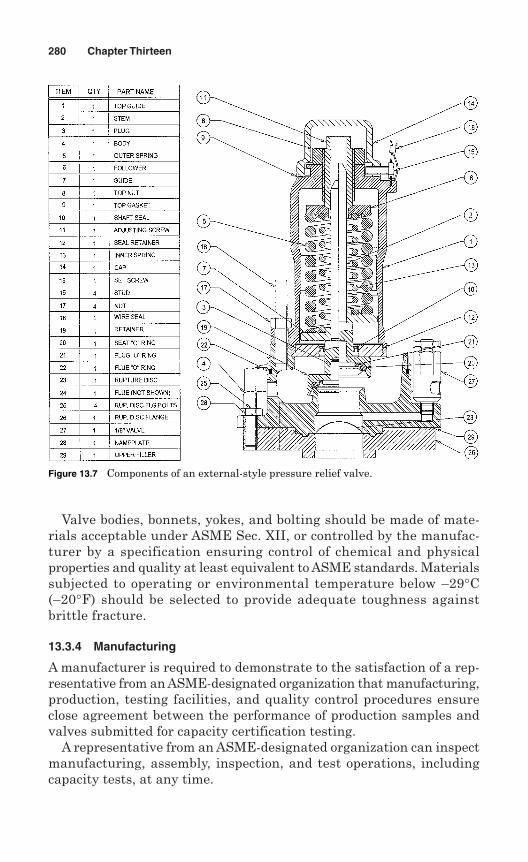
Valve bodies, bonnets, yokes, and bolting should be made of mate-rials acceptable under ASME Sec. XII, or controlled by the manufac-turer by a specification ensuring control of chemical and physicalproperties and quality at least equivalent to ASME standards. Materialssubjected to operating or environmental temperature below –29°C(–20°F) should be selected to provide adequate toughness againstbrittle fracture.
13.3.4 Manufacturing
A manufacturer is required to demonstrate to the satisfaction of a rep-resentative from an ASME-designated organization that manufacturing,production, testing facilities, and quality control procedures ensureclose agreement between the performance of production samples andvalves submitted for capacity certification testing.
A representative from an ASME-designated organization can inspectmanufacturing, assembly, inspection, and test operations, includingcapacity tests, at any time.
280 Chapter Thirteen
Figure 13.7 Components of an external-style pressure relief valve.
If approved by the ASME, a manufacturer is granted permission to applythe Code symbol TV to the production pressure relief valves. This permis-sion expires on the fifth anniversary of the date it is initial granted. Thepermission may be extended for 5-year periods, provided the following testsare successfully repeated within the 6-month period before expiration:
Two sample production pressure relief valves of a size and capacitywithin the capability of an ASME-approved laboratory selected by arepresentative from an ASME-designated organization.
Operational and capacity tests should be performed in the presence ofa representative from an ASME-designated organization at an ASME-approved laboratory. The manufacturer should be notified of the timeof the test and may have representatives present to witness the test.
If any valve fails to relieve at or above its certified capacity or fails tomeet performance criteria, the test should be repeated at the rate oftwo replacement valves for each valve that failed. The selection of thevalve is made according to Par. TR-210.3(c)(1).
If any replacement valve fails to meet the capacity or performancerequirements, the failure will cause revocation of authorization touse the Code symbol within 60 days of such failure. The manufacturermust demonstrate the cause of such deficiency and the correctiveaction taken to guard against future occurrence.
13.3.5 Marking and certification
Each pressure relief valve should be plainly marked by the manufactureror assembler in such a way that the markings will not be obliterated inservice. The markings may be placed either on the valve or on a tagattached to the valve. The minimum markings should include:
1. The name, or an acceptable abbreviation, of the manufacturer orassembler
2. Manufacturer’s design or type number and date of manufacture
3. Nominal seat and inlet connection diameters
4. Set pressure, in bar (psig)
5. Certified flowing capacity at full open pressure, in standard cubic feetper minute, scfm (at 60°F and 14.7 psia) of air, or in standard cubicmeters per hour (at 16°C and 101 kPa) of air where applicable
6. Year built or, alternatively, a date code that enables the valve man-ufacturer or assembler to identify the year the valve was assembledor tested
7. ASME Code symbol as shown in Fig. 13.8
Pressure Relief Devices for Transport Tanks 281
13.3.6 Production testing
The manufacturer is responsible for production testing such as set pres-sure tests and leakage tests before applying the Code symbol TV stampon pressure relief valves. The manufacturer must have a documentedprogram for the application, calibration, and maintenance of gaugesand instruments used during these tests.
The manufacturer must perform the following tests for each pres-sure relief valve to be Code stamped:
Set pressure test—Each pressure relief valve should be tested aftersetting, to demonstrate its set pressure.
Seat tightness test—Each pressure relief valve should be tested forseat tightness after successful completion of the set pressure test.The seat tightness test is done in accordance with API 527.
13.4 Requirements for Rupture Disks
Arupture disk device is a nonreclosing pressure relief device. The pressure-containing element is a rupture disk, which is tested in the factory by themanufacturer. It is actuated by a pressure buildup inside the tank, dueeither to substantial heat input into the tank or pressure spikes generatedby surging liquid in the tank. A rupture disk device used in transport tankapplication is shown in Figs. 13.9 and 13.10.
The burst pressure at the specified disk temperature should notexceed the marked burst pressure by more than ±14 kPa (2 psi) formarked burst pressures up to and including 280 kPa (40 psi), or bymore than ±5% for marked burst pressures above 276 kPa (40 psi) unlessother requirements are identified by the regulating authority.
It is advisable for all personnel to stay away from the rupture diskdevice, unless inspection and maintenance has to be performed on it.Exercise extreme caution when inspecting the rupture disk device and/orits disk if there is any pressure in the tank.
282 Chapter Thirteen
Figure 13.8 ASMECode symbol forpressure reliefvalve for transporttank.
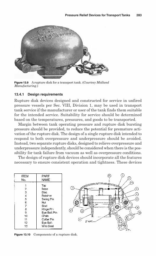
13.4.1 Design requirements
Rupture disk devices designed and constructed for service in unfiredpressure vessels per Sec. VIII, Division 1, may be used in transporttank service if the manufacturer or user of the tank finds them suitablefor the intended service. Suitability for service should be determinedbased on the temperatures, pressures, and goods to be transported.
Margin between tank operating pressure and rupture disk burstingpressure should be provided, to reduce the potential for premature acti-vation of the rupture disk. The design of a single rupture disk intended torespond to both overpressure and underpressure should be avoided.Instead, two separate rupture disks, designed to relieve overpressure andunderpressure independently, should be considered when there is the pos-sibility for tank failure from vacuum as well as overpressure conditions.
The design of rupture disk devices should incorporate all the featuresnecessary to ensure consistent operation and tightness. These devices
Pressure Relief Devices for Transport Tanks 283
Figure 13.9 A rupture disk for a transport tank. (Courtesy MidlandManufacturing.)
Figure 13.10 Components of a rupture disk.
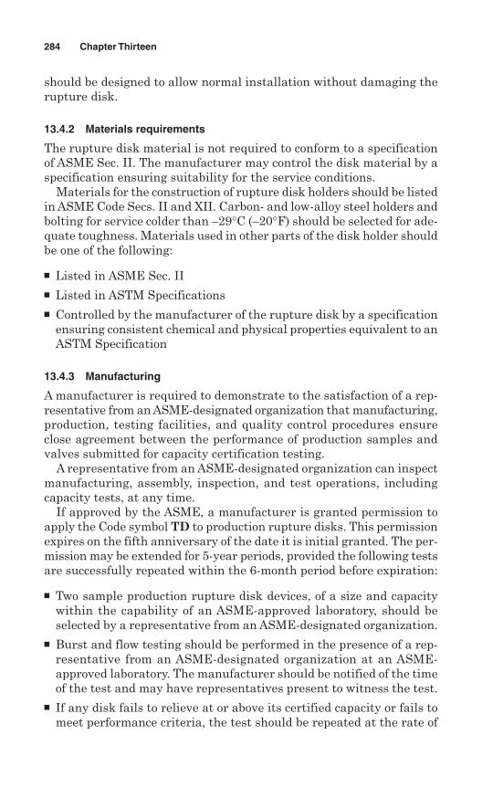
should be designed to allow normal installation without damaging therupture disk.
13.4.2 Materials requirements
The rupture disk material is not required to conform to a specificationof ASME Sec. II. The manufacturer may control the disk material by aspecification ensuring suitability for the service conditions.
Materials for the construction of rupture disk holders should be listedin ASME Code Secs. II and XII. Carbon- and low-alloy steel holders andbolting for service colder than –29°C (–20°F) should be selected for ade-quate toughness. Materials used in other parts of the disk holder shouldbe one of the following:
Listed in ASME Sec. II Listed in ASTM Specifications Controlled by the manufacturer of the rupture disk by a specification
ensuring consistent chemical and physical properties equivalent to anASTM Specification
13.4.3 Manufacturing
A manufacturer is required to demonstrate to the satisfaction of a rep-resentative from an ASME-designated organization that manufacturing,production, testing facilities, and quality control procedures ensureclose agreement between the performance of production samples andvalves submitted for capacity certification testing.
A representative from an ASME-designated organization can inspectmanufacturing, assembly, inspection, and test operations, includingcapacity tests, at any time.
If approved by the ASME, a manufacturer is granted permission toapply the Code symbol TD to production rupture disks. This permissionexpires on the fifth anniversary of the date it is initial granted. The per-mission may be extended for 5-year periods, provided the following testsare successfully repeated within the 6-month period before expiration:
Two sample production rupture disk devices, of a size and capacitywithin the capability of an ASME-approved laboratory, should beselected by a representative from an ASME-designated organization.
Burst and flow testing should be performed in the presence of a rep-resentative from an ASME-designated organization at an ASME-approved laboratory. The manufacturer should be notified of the timeof the test and may have representatives present to witness the test.
If any disk fails to relieve at or above its certified capacity or fails tomeet performance criteria, the test should be repeated at the rate of
284 Chapter Thirteen
two replacement disks for each disk that failed. The selection of thedisks is made according to Pars. TR-310.4(c)(1) and (c)(2).
If any replacement disk fails to meet the capacity or performancerequirements, the failure will be cause for revocation of authorizationto use the Code symbol within 60 days of such failure. The manufac-turer must demonstrate the cause of such deficiency and the correc-tive action taken to guard against future occurrence.
13.4.4 Marking and certification
Every rupture disk should be plainly marked by the manufacturer in sucha way that the markings will not be obliterated in service. The rupture diskmarkings may be placed on the flange of the disk, or on a tab attached asclose as possible to the discharge side of the disk so that it will be visiblewhen installed. The markings should include the following:
1. Name or identifying trademark of the manufacturer
2. Manufacturer’s design or type number
3. Lot number
4. Disk material
5. Size (NPS or nominal diameter, in or mm)
6. Marked bursting pressure, in psig; an in bar where applicable
7. Specified disk temperature, °F, and °C where applicable
8. Minimum net flow area, in2 (cm2)
9. Certified flow resistance coefficient, Kr
10. ASME Code symbol as shown in Fig. 13.11
11. Year built or, alternatively, a date code that enables the disk man-ufacturer or disk assembler to identify the year the disk was man-ufactured or the disk and holder assembly was assembled
Pressure Relief Devices for Transport Tanks 285
Figure 13.11 ASME codesymbol for rupture diskfor transport tank.
13.4.5 Production testing
The manufacturer is responsible for production testing such as pressuretests, set pressure tests, and leakage tests before applying the Codesymbol TD to rupture disks. The manufacturer must have a documentedprogram for the application, calibration, and maintenance of gaugesand instruments used during these tests.
The manufacturer must perform the following tests for rupture disksto be Code stamped:
Pressure test—The pressure parts of each rupture disk holder exceed-ing DN 25 (NPS 1) inlet size or 2 070 kPa (300 psi) design pressurewhere materials are either cast or welded should be tested at a pres-sure of 1.3 times the design pressure. The result of the test shouldshow no sign of leakage.
Burst test—Each lot of rupture disks should be tested for bursting. Alot of rupture disk means the quantity of disks manufactured of agiven material specification at the same time, of the same size, thick-ness type, heat, heat-treatment condition, and manufacturing process.The manufacturer is responsible for conducting the following tests: Atleast two sample rupture disks from each lot should be burst at thespecific disk temperature. The burst pressure should be within theburst pressure tolerance specified by TR-300(b).
13.4.6 Installation requirements
A rupture disk may be either installed as the sole pressure-relievingdevice on the vessel or installed between a pressure relief valve and thetank. A rupture disk should not be installed on the discharge side of apressure relief valve.
The following criteria should be met if a rupture disk is installedbetween a pressure relief valve and a tank:
The combined flow capacity of the spring-loaded pressure relief valveand the rupture disk should be sufficient to meet the requirements ofArt. TR-1 of the Modal Appendices.
The marked capacity of a pressure relief valve when installed with arupture disk should be multiplied by a factor of 0.90 of the ratedrelieving capacity of the valve alone.
The space between a rupture disk device and a pressure relief valveshould be provided with a pressure gauge, try cock, free vent, or othersuitable telltale indicator. This will permit detection of disk ruptureor leakage at pressures lower than the set point of the valve.
286 Chapter Thirteen
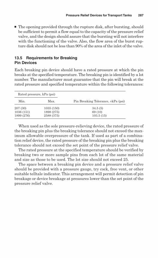
The opening provided through the rupture disk, after bursting, shouldbe sufficient to permit a flow equal to the capacity of the pressure reliefvalve, and the design should assure that the bursting will not interferewith the functioning of the valve. Also, the flow area of the burst rup-ture disk should not be less than 90% of the area of the inlet of the valve.
13.5 Requirements for BreakingPin Devices
Each breaking pin device should have a rated pressure at which the pinbreaks at the specified temperature. The breaking pin is identified by a lotnumber. The manufacturer must guarantee that the pin will break at therated pressure and specified temperature within the following tolerances:
Rated pressure, kPa (psi)
Min. Max. Pin Breaking Tolerance, ±kPa (psi)
207 (30) 1035 (150) 34.5 (5)1036 (151) 1898 (275) 69 (10)1899 (276) 2588 (375) 103.5 (15)
When used as the sole pressure-relieving device, the rated pressure ofthe breaking pin plus the breaking tolerance should not exceed the max-imum allowable overpressure of the tank. If used as part of a combina-tion relief device, the rated pressure of the breaking pin plus the breakingtolerance should not exceed the set point of the pressure relief valve.
The rated pressure at the specified temperature should be verified bybreaking two or more sample pins from each lot of the same materialand size as those to be used. The lot size should not exceed 25.
The space between a breaking pin device and a pressure relief valveshould be provided with a pressure gauge, try cock, free vent, or othersuitable telltale indicator. This arrangement will permit detection of pinbreakage or device breakage at pressures lower than the set point of thepressure relief valve.
Pressure Relief Devices for Transport Tanks 287

This page intentionally left blank
Chapter
Pressure Relief Devicesfor Petroleum Industries
The petroleum industry began with the drilling of the first commercialoil well in 1859 and the opening of the first refinery two years later toprocess the crude oil into kerosene. The evolution of refining from simpledistillation to modern sophisticated processes has created a need forsafety. The safe processing of crude oil into flammable gases and liquidsat high temperatures and pressures using pressure vessels, equipment,and piping subjected to stress and corrosion requires considerable knowl-edge, control, and expertise. These vessels are specially designed towithstand the corrosive environment of petroleum products.
Pressure-relieving devices protect pressure vessels, equipment, andpiping in the petroleum industry by automatically opening at prede-termined pressures and preventing the destructive consequences ofexcessive pressures in process systems and storage vessels.
The American Petroleum Institute (API) is the primary trade associa-tion, representing more than 400 members in all aspects of the oil andgas industry. API members come from all segments of the industry, fromthe largest major oil company to the smallest of independents. They areproducers, refiners, suppliers, pipeline operators, and marine trans-porters. The API has published many codes and standards for the oil andgas industry, but the following standards are applicable to pressure-relieving devices:
API 510: Pressure Vessel Inspection Code: Inspection, Rating, Repair,and Alteration
RP 520: Sizing, Selection, and Installation of Pressure RelievingDevices in Refineries
289
14
Copyright © 2006 by The McGraw-Hill Companies, Inc. Click here for terms of use.
Part I—Sizing and SelectionPart II—Installation
RP 521: Guide for Pressure-Relieving and Depressuring SystemsStd 526: Flanged Steel Pressure Relief ValvesStd 527: Seat Tightness of Pressure Relief Valves
RP 576: Inspection of Pressure Relieving DevicesStd 620: Design and Construction of Large, Welded, Low-PressureStorage TanksStd 650: Welded Steel Tanks for Oil StorageStd 2000: Venting Atmospheric and Low-Pressure Storage Tanks
Bull. 2521: Use of Pressure-Vacuum Vent Valves for AtmosphericPressure Tanks to Reduce Evaporation Loss
14.1 Refining Operations
Refining is the process of converting one complex mixture of hydrocar-bons into a number of complex mixtures of hydrocarbons. A petroleumrefining process is shown in Fig. 14.1. Petroleum refining begins withthe distillation, or fraction, of crude oils (Fig. 14.2) into separate hydro-carbon groups.
Petroleum refining processes and operations can be separated into sixbasic areas:
1. Fractionation (distillation)—separation of crude oil in atmosphericand vacuum towers into groups of hydrocarbon compounds
2. Conversion—processes for changing the size and/or structure ofhydrocarbon molecules
3. Treatment—processes for preparing hydrocarbon streams for addi-tional processes to prepare finished products
4. Formulating and blending—processes of mixing and combininghydrocarbon fractional additives and other components to produce fin-ished products
5. Other refining operations—including light-ends recovery, sour-waterstripping, solid waste water treatment, process water treatment,cooling, storage (Fig. 14.3) and handling, hydrogen production, acidand tail gas treatment, and sulfur recovery
6. Auxiliary operations and facilities—including steam and power gen-eration, process and fire water systems, flares and relief systems, fur-naces and heaters, pumps and valves, supply of nitrogen and otherplant gases, etc.
290 Chapter Fourteen
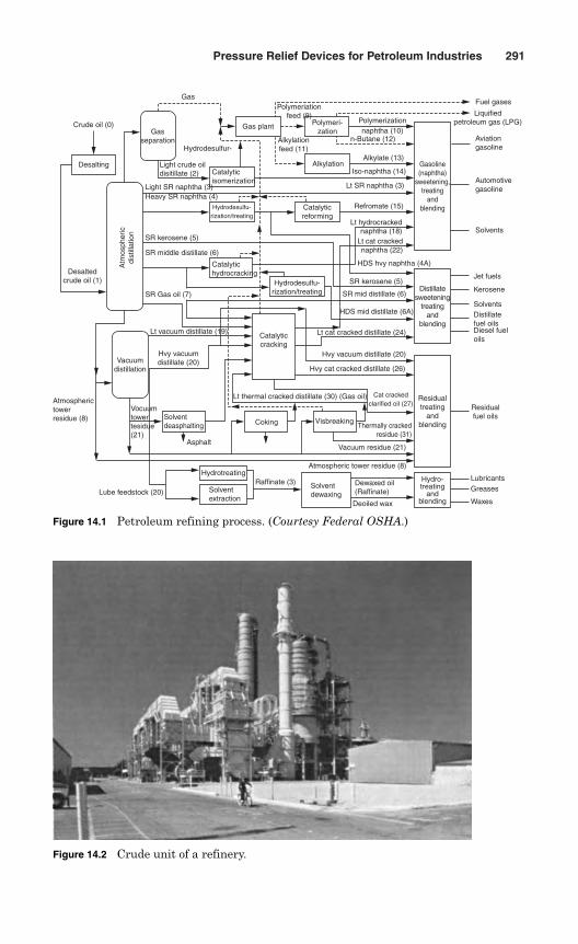
Pressure Relief Devices for Petroleum Industries 291
Vocuumtowertesidue(21)
Desalting
Gasseparation
Hydrodesulfur-
Light crude oildisitillate (2)
Light SR naphtha (3)Heavy SR naphtha (4)
SR kerosene (5)
SR middle distillate (6)
SR Gas oil (7)
Catalyticisomerization
Catalytichydrocracking
Lt vacuum distillate (19)
Vacuumdistillation
Hvy vacuum distillate (20)
Atmospherictowerresidue (8)
Asphalt
Lube feedstock (20)
Hydrotreating
Solventextraction
Raffinate (3) Solventdewaxing
Deoiled wax
Dewaxed oil(Raffinate)
Hydro-treating
andblending
LubricantsGreases
Waxes
Atmospheric tower residue (8)
Vacuum residue (21)
VisbreakingCoking
Catalyticcracking
Hydrodesulfu-rization/treating
Jet fuels
Kerosene
SolventsDistillatefuel oilsDiesel fueloils
Solvents
Automotivegasoline
Aviationgasoline
Fuel gases
Liquifiedpetroleum gas (LPG)
Gas plantPolymerization naphtha (10)
Polymeri-zation
Alkylation
n-Butane (12)
Alkylate (13)
Iso-naphtha (14)
Lt SR naphtha (3)
Refromate (15)
Lt hydrocracked naphtha (18)
Lt cat crackednaphtha (22)
HDS hvy naphtha (4A)
SR kerosene (5)
SR mid distillate (6)
HDS mid distillate (6A)
Lt cat cracked distillate (24)
Hvy vacuum distillate (20)
Hvy cat cracked distillate (26)
Lt thermal cracked distillate (30) (Gas oil) Residualtreating
andblending
Residualfuel oils
Catalyticreforming
Desaltedcrude oil (1)
Atm
osph
eric
dist
illat
ion
Crude oil (0)
GasPolymeriation
feed (9)
Alkylationfeed (11)
Figure 14.1 Petroleum refining process. (Courtesy Federal OSHA.)
Figure 14.2 Crude unit of a refinery.
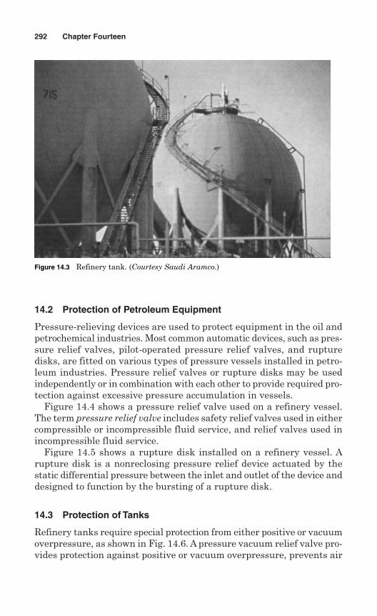
14.2 Protection of Petroleum Equipment
Pressure-relieving devices are used to protect equipment in the oil andpetrochemical industries. Most common automatic devices, such as pres-sure relief valves, pilot-operated pressure relief valves, and rupturedisks, are fitted on various types of pressure vessels installed in petro-leum industries. Pressure relief valves or rupture disks may be usedindependently or in combination with each other to provide required pro-tection against excessive pressure accumulation in vessels.
Figure 14.4 shows a pressure relief valve used on a refinery vessel.The term pressure relief valve includes safety relief valves used in eithercompressible or incompressible fluid service, and relief valves used inincompressible fluid service.
Figure 14.5 shows a rupture disk installed on a refinery vessel. Arupture disk is a nonreclosing pressure relief device actuated by thestatic differential pressure between the inlet and outlet of the device anddesigned to function by the bursting of a rupture disk.
14.3 Protection of Tanks
Refinery tanks require special protection from either positive or vacuumoverpressure, as shown in Fig. 14.6. A pressure vacuum relief valve pro-vides protection against positive or vacuum overpressure, prevents air
292 Chapter Fourteen
Figure 14.3 Refinery tank. (Courtesy Saudi Aramco.)
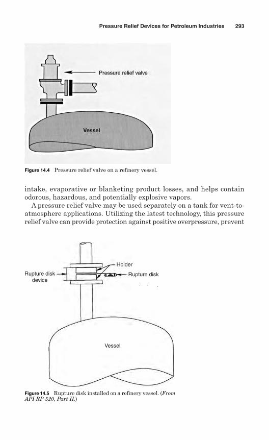
intake, evaporative or blanketing product losses, and helps containodorous, hazardous, and potentially explosive vapors.
A pressure relief valve may be used separately on a tank for vent-to-atmosphere applications. Utilizing the latest technology, this pressurerelief valve can provide protection against positive overpressure, prevent
Pressure Relief Devices for Petroleum Industries 293
Figure 14.4 Pressure relief valve on a refinery vessel.
Holder
Rupture diskRupture diskdevice
Vessel
Figure 14.5 Rupture disk installed on a refinery vessel. (FromAPI RP 520, Part II.)
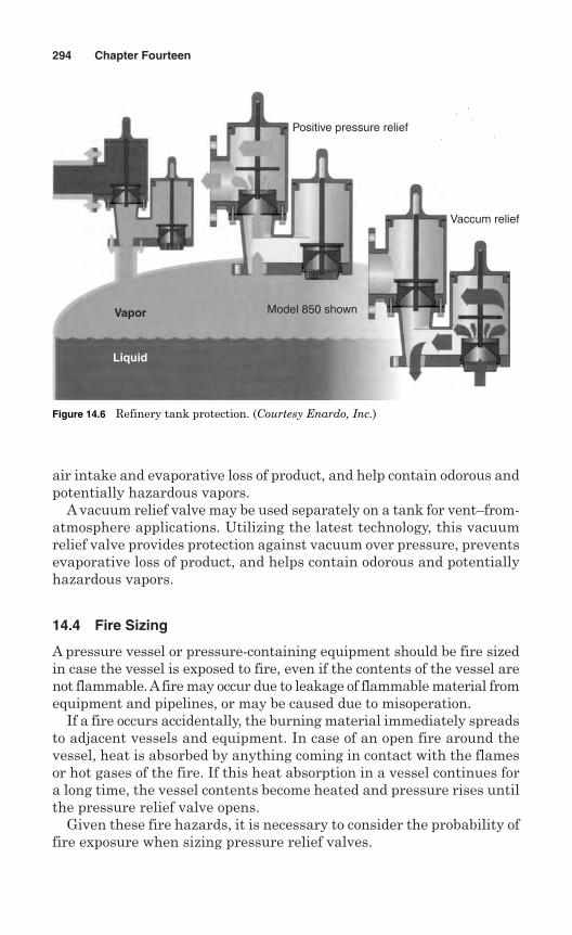
air intake and evaporative loss of product, and help contain odorous andpotentially hazardous vapors.
A vacuum relief valve may be used separately on a tank for vent–from-atmosphere applications. Utilizing the latest technology, this vacuumrelief valve provides protection against vacuum over pressure, preventsevaporative loss of product, and helps contain odorous and potentiallyhazardous vapors.
14.4 Fire Sizing
A pressure vessel or pressure-containing equipment should be fire sizedin case the vessel is exposed to fire, even if the contents of the vessel arenot flammable. A fire may occur due to leakage of flammable material fromequipment and pipelines, or may be caused due to misoperation.
If a fire occurs accidentally, the burning material immediately spreadsto adjacent vessels and equipment. In case of an open fire around thevessel, heat is absorbed by anything coming in contact with the flamesor hot gases of the fire. If this heat absorption in a vessel continues fora long time, the vessel contents become heated and pressure rises untilthe pressure relief valve opens.
Given these fire hazards, it is necessary to consider the probability offire exposure when sizing pressure relief valves.
294 Chapter Fourteen
Positive pressure relief
Vaccum relief
Model 850 shownVapor
Liquid
Figure 14.6 Refinery tank protection. (Courtesy Enardo, Inc.)
14.4.1 Fire sizing standards
The rules for fire sizing depend on the codes, standards, and jurisdic-tional requirements at the location of installation. The following stan-dards are recommended in additional to the jurisdictional requirementsfor fire sizing of pressure relief devices:
API RP 520 Part 1, Recommended Practices for the Design andInstallation of Pressure-Relieving Systems in Refineries
API Standard 2000, Venting Atmospheric and Low Pressure StorageTanks
API Standard 2510, Design of LP Gas Installations NFPA (National Fire Protection Association) 58—Storage and
Handling of Liquefied Petroleum Gases CGA (Compressed Gas Association), CGA S-13
14.4.2 Fire sizing for liquid hydrocarbons
Most of the hydrocarbon liquid is stored in a tank. The following infor-mation is needed to calculate the required orifice area for pressure reliefvalves on vessels containing liquids that are exposed to fire:
Tank size (shape and dimensions) Mounting (horizontal or vertical; height above ground) Fluid composition Normal liquid level (NLL): % full, depth of fluid, or liquid-full Operating pressure Set pressure Operating temperature Saturation temperature at P1
K (ratio of specific heat) M (molecular weight) Z (compressibility factor); if not known, assume Z = 1 F environmental factor: The F factors in Table 14.1 should be used
in the calculation. If sufficient information is not available, assumeF = 1.
Based on the above information, the following steps may be followed infire sizing a tank containing liquid hydrocarbons.
Pressure Relief Devices for Petroleum Industries 295
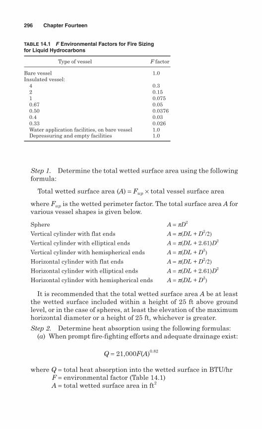
Step 1. Determine the total wetted surface area using the followingformula:
Total wetted surface area (A) = Fwp × total vessel surface area
where Fwp is the wetted perimeter factor. The total surface area A forvarious vessel shapes is given below.
Sphere A = pD2
Vertical cylinder with flat ends A = p(DL + D2/2)Vertical cylinder with elliptical ends A = p(DL + 2.61)D2
Vertical cylinder with hemispherical ends A = p(DL + D2)Horizontal cylinder with flat ends A = p(DL + D2/2)Horizontal cylinder with elliptical ends A = p(DL + 2.61)D2
Horizontal cylinder with hemispherical ends A = p(DL + D2)
It is recommended that the total wetted surface area A be at leastthe wetted surface included within a height of 25 ft above groundlevel, or in the case of spheres, at least the elevation of the maximumhorizontal diameter or a height of 25 ft, whichever is greater.
Step 2. Determine heat absorption using the following formulas:(a) When prompt fire-fighting efforts and adequate drainage exist:
Q = 21,000F(A)0.82
where Q = total heat absorption into the wetted surface in BTU/hrF = environmental factor (Table 14.1) A = total wetted surface area in ft2
296 Chapter Fourteen
TABLE 14.1 F Environmental Factors for Fire Sizingfor Liquid Hydrocarbons
Type of vessel F factor
Bare vessel 1.0Insulated vessel:
4 0.32 0.151 0.0750.67 0.050.50 0.03760.4 0.030.33 0.026Water application facilities, on bare vessel 1.0Depressuring and empty facilities 1.0
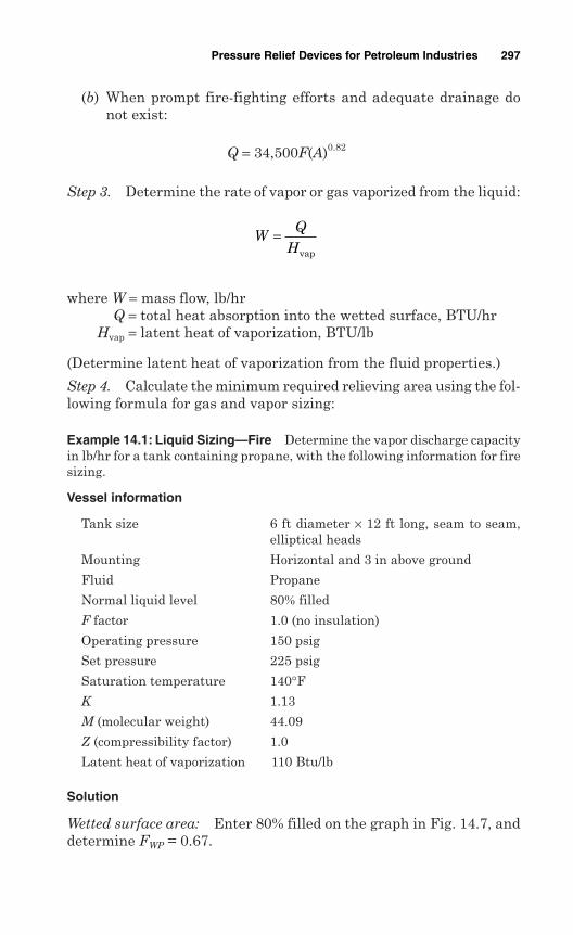
(b) When prompt fire-fighting efforts and adequate drainage donot exist:
Q = 34,500F(A)0.82
Step 3. Determine the rate of vapor or gas vaporized from the liquid:
where W = mass flow, lb/hrQ = total heat absorption into the wetted surface, BTU/hr
Hvap = latent heat of vaporization, BTU/lb
(Determine latent heat of vaporization from the fluid properties.)
Step 4. Calculate the minimum required relieving area using the fol-lowing formula for gas and vapor sizing:
Example 14.1: Liquid Sizing—Fire Determine the vapor discharge capacityin lb/hr for a tank containing propane, with the following information for firesizing.
Vessel information
Tank size 6 ft diameter × 12 ft long, seam to seam,elliptical heads
Mounting Horizontal and 3 in above ground
Fluid Propane
Normal liquid level 80% filled
F factor 1.0 (no insulation)
Operating pressure 150 psig
Set pressure 225 psig
Saturation temperature 140°FK 1.13
M (molecular weight) 44.09
Z (compressibility factor) 1.0
Latent heat of vaporization 110 Btu/lb
Solution
Wetted surface area: Enter 80% filled on the graph in Fig. 14.7, anddetermine FWP = 0.67.
WQ
H=
vap
Pressure Relief Devices for Petroleum Industries 297
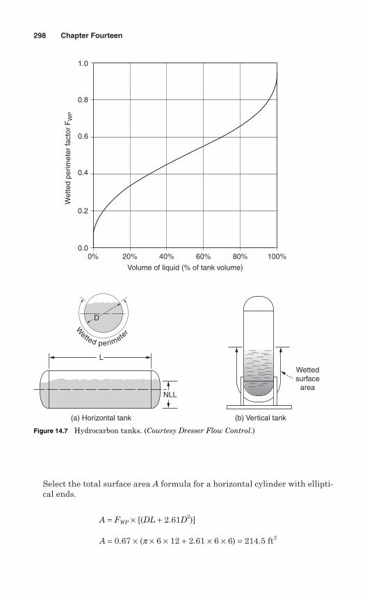
Select the total surface area A formula for a horizontal cylinder with ellipti-cal ends.
A = FWP × [(DL + 2.61D2)]
A = 0.67 × (p × 6 × 12 + 2.61 × 6 × 6) = 214.5 ft2
298 Chapter Fourteen
1.0
0.8
0.6
Wet
ted
perim
eter
fact
or F
WP
0.4
0.2
0.00% 20% 40% 60% 80% 100%
Volume of liquid (% of tank volume)
Wettedsurface
area
(b) Vertical tank
D
W
etted perimete
r
L
NLL
(a) Horizontal tank
Figure 14.7 Hydrocarbon tanks. (Courtesy Dresser Flow Control.)
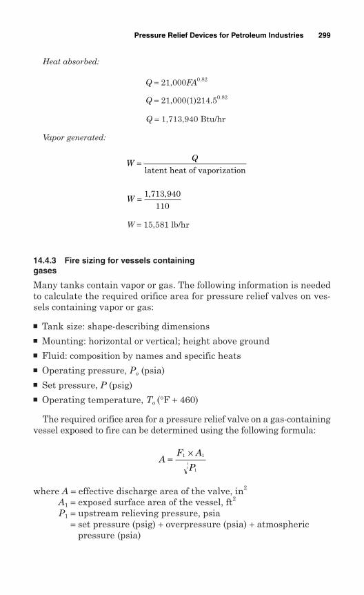
Heat absorbed:
Q = 21,000FA0.82
Q = 21,000(1)214.50.82
Q = 1,713,940 Btu/hr
Vapor generated:
W = 15,581 lb/hr
14.4.3 Fire sizing for vessels containinggases
Many tanks contain vapor or gas. The following information is neededto calculate the required orifice area for pressure relief valves on ves-sels containing vapor or gas:
Tank size: shape-describing dimensions Mounting: horizontal or vertical; height above ground Fluid: composition by names and specific heats Operating pressure, Po (psia) Set pressure, P (psig) Operating temperature, To (°F + 460)
The required orifice area for a pressure relief valve on a gas-containingvessel exposed to fire can be determined using the following formula:
where A = effective discharge area of the valve, in2
A1 = exposed surface area of the vessel, ft2
P1 = upstream relieving pressure, psia= set pressure (psig) + overpressure (psia) + atmospheric
pressure (psia)
AF A
P=
×1 1
1
W = 1 713 940110
, ,
WQ=
latent heat of vaporization
Pressure Relief Devices for Petroleum Industries 299
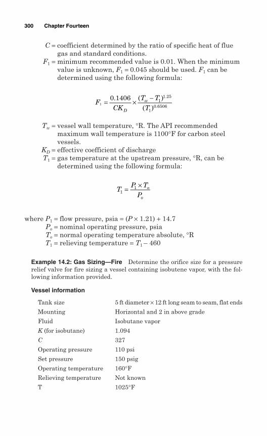
C = coefficient determined by the ratio of specific heat of fluegas and standard conditions.
F1 = minimum recommended value is 0.01. When the minimumvalue is unknown, F1 = 0.045 should be used. F1 can bedetermined using the following formula:
Tw = vessel wall temperature, °R. The API recommendedmaximum wall temperature is 1100°F for carbon steelvessels.
KD = effective coefficient of dischargeT1 = gas temperature at the upstream pressure, °R, can be
determined using the following formula:
where P1 = flow pressure, psia = (P × 1.21) + 14.7Po = nominal operating pressure, psiaTo = normal operating temperature absolute, °RT1 = relieving temperature = T1 – 460
Example 14.2: Gas Sizing—Fire Determine the orifice size for a pressurerelief valve for fire sizing a vessel containing isobutene vapor, with the fol-lowing information provided.
Vessel information
Tank size 5 ft diameter × 12 ft long seam to seam, flat ends
Mounting Horizontal and 2 in above grade
Fluid Isobutane vapor
K (for isobutane) 1.094
C 327
Operating pressure 110 psi
Set pressure 150 psig
Operating temperature 160°FRelieving temperature Not known
T 1025°F
TP T
Po
o1
1= ×
FCK
T TTD
w1
0 1406 11 25
10 6506
= × −. ( )( )
.
.
300 Chapter Fourteen
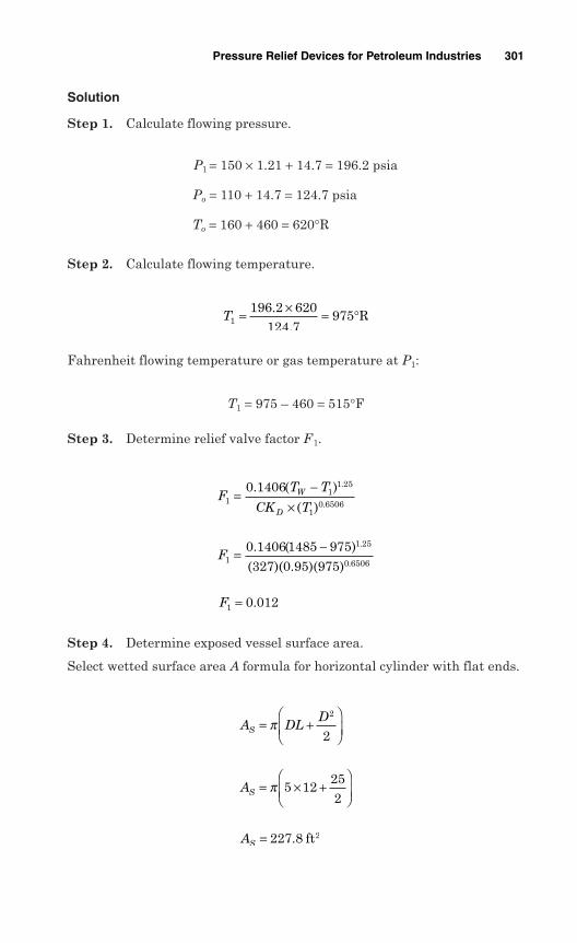
Solution
Step 1. Calculate flowing pressure.
P1 = 150 × 1.21 + 14.7 = 196.2 psia
Po = 110 + 14.7 = 124.7 psia
To = 160 + 460 = 620°R
Step 2. Calculate flowing temperature.
Fahrenheit flowing temperature or gas temperature at P1:
T1 = 975 – 460 = 515°F
Step 3. Determine relief valve factor F1.
Step 4. Determine exposed vessel surface area.
Select wetted surface area A formula for horizontal cylinder with flat ends.
AS = 227 8. ft2
AS = × +
π 5 12
252
A DLD
S = +
π
2
2
F1 0 012= .
F1
1 25
0 6506
0 1406 1485 975
327 0 95 975= −. ( )
( )( . )( )
.
.
FT T
CK TW
D1
11 25
10 6506
0 1406=
−×
. ( )
( )
.
.
T1196 2 620
124 7975= × = °.
.R
Pressure Relief Devices for Petroleum Industries 301
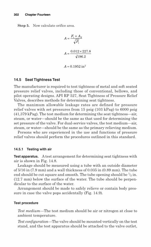
Step 5. Now calculate orifice area.
14.5 Seat Tightness Test
The manufacturer is required to test tightness of metal and soft seatedpressure relief valves, including those of conventional, bellows, andpilot operating designs. API RP 527, Seat Tightness of Pressure ReliefValves, describes methods for determining seat tightness.
The maximum allowable leakage rates are defined for pressurerelief valves with set pressures from 15 psig (103 kPag) to 6000 psig(41,379 kPag). The test medium for determining the seat tightness—air,steam, or water—should be the same as that used for determining theset pressure of the valve. For dual-service valves, the test medium—air,steam, or water—should be the same as the primary relieving medium.
Persons who are experienced in the use and functions of pressurerelief valves should perform the procedures outlined in this standard.
14.5.1 Testing with air
Test apparatus. A test arrangement for determining seat tightness withair is shown in Fig. 14.8.
Leakage should be measured using a tube with an outside diameterof 5/16 in (7.9 mm) and a wall thickness of 0.035 in (0.89 mm). The tubeend should be cut square and smooth. The tube opening should be 1/2 in.(12.7 mm) below the surface of the water. The tube should be perpen-dicular to the surface of the water.
Arrangement should be made to safely relieve or contain body pres-sure in case the valve pops accidentally (Fig. 14.9).
Test procedure
Test medium—The test medium should be air or nitrogen at close toambient temperature.
Test configuration—The valve should be mounted vertically on the teststand, and the test apparatus should be attached to the valve outlet,
A = 0 1952. in2
A = ×0 012 227 8
196 2
. .
.
AF A
PS=
×1
1
302 Chapter Fourteen
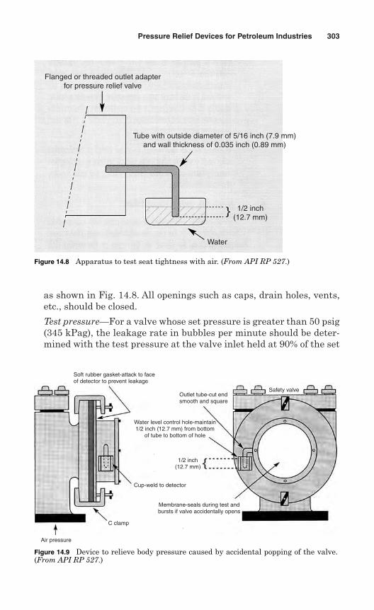
as shown in Fig. 14.8. All openings such as caps, drain holes, vents,etc., should be closed.
Test pressure—For a valve whose set pressure is greater than 50 psig(345 kPag), the leakage rate in bubbles per minute should be deter-mined with the test pressure at the valve inlet held at 90% of the set
Pressure Relief Devices for Petroleum Industries 303
Flanged or threaded outlet adapterfor pressure relief valve
Tube with outside diameter of 5/16 inch (7.9 mm)and wall thickness of 0.035 inch (0.89 mm)
1/2 inch(12.7 mm)
Water
Figure 14.8 Apparatus to test seat tightness with air. (From API RP 527.)
Air pressure
C clamp
Cup-weld to detector
Soft rubber gasket-attack to faceof detector to prevent leakage
Outlet tube-cut endsmooth and square
Water level control hole-maintain1/2 inch (12.7 mm) from bottom
of tube to bottom of hole
1/2 inch(12.7 mm)
Membrane-seals during test andbursts if valve accidentally opens
Safety valve
Figure 14.9 Device to relieve body pressure caused by accidental popping of the valve.(From API RP 527.)
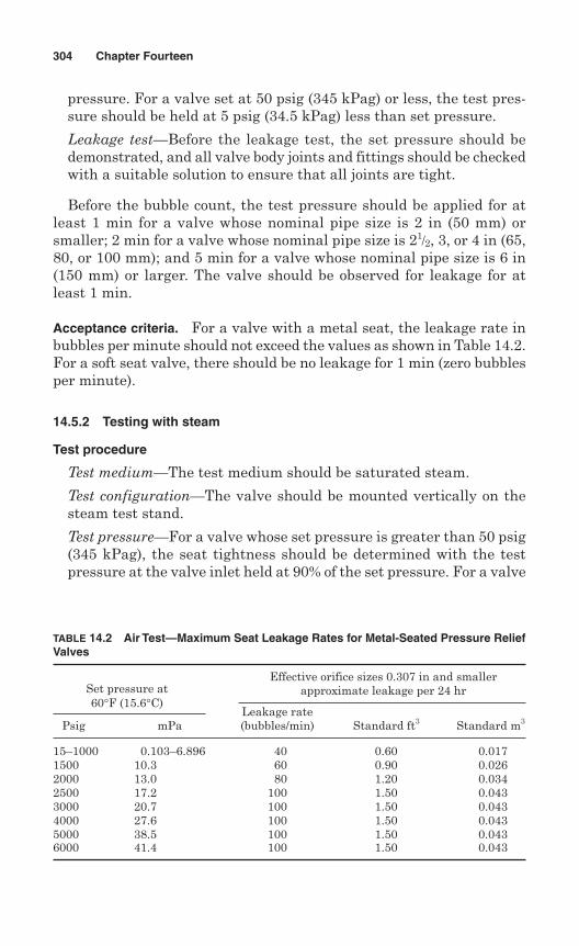
pressure. For a valve set at 50 psig (345 kPag) or less, the test pres-sure should be held at 5 psig (34.5 kPag) less than set pressure.
Leakage test—Before the leakage test, the set pressure should bedemonstrated, and all valve body joints and fittings should be checkedwith a suitable solution to ensure that all joints are tight.
Before the bubble count, the test pressure should be applied for atleast 1 min for a valve whose nominal pipe size is 2 in (50 mm) orsmaller; 2 min for a valve whose nominal pipe size is 21/2, 3, or 4 in (65,80, or 100 mm); and 5 min for a valve whose nominal pipe size is 6 in(150 mm) or larger. The valve should be observed for leakage for atleast 1 min.
Acceptance criteria. For a valve with a metal seat, the leakage rate inbubbles per minute should not exceed the values as shown in Table 14.2.For a soft seat valve, there should be no leakage for 1 min (zero bubblesper minute).
14.5.2 Testing with steam
Test procedure
Test medium—The test medium should be saturated steam.
Test configuration—The valve should be mounted vertically on thesteam test stand.
Test pressure—For a valve whose set pressure is greater than 50 psig(345 kPag), the seat tightness should be determined with the testpressure at the valve inlet held at 90% of the set pressure. For a valve
304 Chapter Fourteen
TABLE 14.2 Air Test—Maximum Seat Leakage Rates for Metal-Seated Pressure ReliefValves
Set pressure atEffective orifice sizes 0.307 in and smaller
60°F (15.6°C)approximate leakage per 24 hr
Leakage ratePsig mPa (bubbles/min) Standard ft3 Standard m3
15–1000 0.103–6.896 40 0.60 0.0171500 10.3 60 0.90 0.0262000 13.0 80 1.20 0.0342500 17.2 100 1.50 0.0433000 20.7 100 1.50 0.0434000 27.6 100 1.50 0.0435000 38.5 100 1.50 0.0436000 41.4 100 1.50 0.043
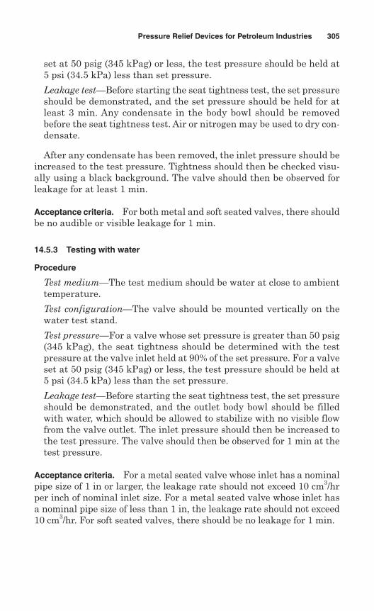
set at 50 psig (345 kPag) or less, the test pressure should be held at5 psi (34.5 kPa) less than set pressure.
Leakage test—Before starting the seat tightness test, the set pressureshould be demonstrated, and the set pressure should be held for atleast 3 min. Any condensate in the body bowl should be removedbefore the seat tightness test. Air or nitrogen may be used to dry con-densate.
After any condensate has been removed, the inlet pressure should beincreased to the test pressure. Tightness should then be checked visu-ally using a black background. The valve should then be observed forleakage for at least 1 min.
Acceptance criteria. For both metal and soft seated valves, there shouldbe no audible or visible leakage for 1 min.
14.5.3 Testing with water
Procedure
Test medium—The test medium should be water at close to ambienttemperature.
Test configuration—The valve should be mounted vertically on thewater test stand.
Test pressure—For a valve whose set pressure is greater than 50 psig(345 kPag), the seat tightness should be determined with the testpressure at the valve inlet held at 90% of the set pressure. For a valveset at 50 psig (345 kPag) or less, the test pressure should be held at5 psi (34.5 kPa) less than the set pressure.
Leakage test—Before starting the seat tightness test, the set pressureshould be demonstrated, and the outlet body bowl should be filledwith water, which should be allowed to stabilize with no visible flowfrom the valve outlet. The inlet pressure should then be increased tothe test pressure. The valve should then be observed for 1 min at thetest pressure.
Acceptance criteria. For a metal seated valve whose inlet has a nominalpipe size of 1 in or larger, the leakage rate should not exceed 10 cm3/hrper inch of nominal inlet size. For a metal seated valve whose inlet hasa nominal pipe size of less than 1 in, the leakage rate should not exceed10 cm3/hr. For soft seated valves, there should be no leakage for 1 min.
Pressure Relief Devices for Petroleum Industries 305

This page intentionally left blank
Chapter
Installation
Installation of pressure relief devices requires careful consideration.Marginal installation can render the pressure relief devices inoperableor severely restrict their abilities to perform properly and cause highmaintenance costs.
Pressure relief devices are installed according to the local jurisdic-tional rules and national codes. Good engineering practices should beexercised if there are no rules in the jurisdiction having authority.
Installation of pressure relief valves should be done by organizationsexperienced in installation, repair, maintenance, and testing. The installermust comply with the requirements of the following standards and codes:
ASME Sec. 1, Power BoilersPars. PG-67 through PG-73
ASME Sec. IV—Heating BoilersArticle 4—Pressure Relieving DevicesArticle 8—Installation Requirements
ASME Sec. VIII, Division 1, Pressure VesselsNonmandatory Appendix M—Installation and Operation
ASME B31.1 Pressure PipingNonmandatory Appendix II—Rules for the Design of Safety ValveInstallations
API RP 520—Sizing, Selection, and Installation of Pressure RelievingDevices in RefineriesPart I—Sizing and SelectionPart II—Installation
API RP 521—Guide for Pressure-Relieving and Depressing Systems API RP 576—Inspection of Pressure-Relieving Devices
307
15
Copyright © 2006 by The McGraw-Hill Companies, Inc. Click here for terms of use.
15.1 Installation of Pressure Relief Valves
Pressure relief valves normally should be installed in the upright posi-tion with the spindle vertical. The valve may be installed in other posi-tion than the vertical position provided that:
The valve design is satisfactory for such position The media is such that material will not accumulate at the inlet of the
valve; and Drainage of the discharge side of the valve body and discharge piping
is adequate
The pressure relief valves should be installed in such a way that theirproper functioning will not be hampered by the vessel’s contents. Thevalves for use in compressible fluid service should be connected to thevessel in the vapor space above any contained liquid or to piping con-nected to the vapor space in the vessel. Pressure relief valves intendedfor use in liquid service should be connected below normal liquid level.
The opening through all pipes and fittings between a pressure vesseland its pressure relief valve should have at least the area of the pres-sure relief valve inlet. The openings in the vessel should be designed toprovide unrestricted flow between the vessel and its pressure reliefvalve.
There should be no intervening stop valves between the vessel and itspressure relief valve or between the pressure relief valve and the pointof discharge. There are also rules for installation of inlet and dischargepiping to and from pressure relief valves. In summary, the installationof pressure relief valves should cover the following areas:
Preinstallation handling and storage Inlet piping Discharge piping Vent piping Drain piping Isolation valves
15.1.1 Preinstallation handling and testing
Proper preinstallation handling and testing can help ensure that pres-sure relief valves and their associated piping remain clean, free ofdamage, and operational.
Pressure relief valves should be handled very carefully. The internalparts of pressure relief valves are precision machined and fitted together
308 Chapter Fifteen
to maintain perfect alignment. Rough handling of valves may damagethe seats or cause misalignment that can lead to leakage.
Handling and storage. Pressure relief valves are checked for tightnessin the manufacturer’s shop before they are shipped to the owner. Thepressure relief valves should be shipped in an upright position. Thisis especially important for large valves and valves with low pressuresettings.
Pressure relief valves should be handled carefully. The valves areshipped with a protective covering over the inlet and the outlet to pre-vent damage to the flanged surfaces and to prevent entry of foreignparticles. The protective covering should be left intact if valves arerequired to be stored before installation. It is recommended to use a cleanand dry covered area for storage of pressure relief valves.
Inspection and testing. The condition of all pressure relief valves shouldbe inspected visually when the shipment is received. The manufac-turer’s recommendation should be followed for details relating to the spe-cific valve. All protective materials should be removed beforeinstallation. The valves should be tested before installation to confirmtheir opening pressure setting.
Cleaning of systems. The systems on which the valves are installedshould be thoroughly inspected and cleaned. If possible, the systemshould be purged before the valve is installed. The valve should be keptisolated during pressure testing of the system, either by blanking or byclosing a stop valve.
15.1.2 Inlet piping
It is extremely important that the inlet piping to pressure valves isdesigned properly. Sometimes, pressure relief valves are installed atthe most physically convenient location, without properly consideringflow conditions.
Pressure loss can occur during flow in an inlet pipe. The pressure lossin an inlet pipe may be large, between 10% and 30%, or as small as 3%,depending on the size, geometry, and inside condition of the pipe. APIRP 520, Part 2, and ASME Code Sec. VIII, Division 1, recommend a max-imum inlet pressure loss to a pressure relief valve of 3%. This pressureloss is the sum of the total losses due to penetration configuration at thevessel, inlet pipe loss, and, when a block valve is used, loss through it.The losses should be calculated using the maximum actual rated flowthrough the pressure relief valve, using KD, not K. Pressure drop limi-tations and piping configurations are shown in Figs. 15.1 and 15.2.
Installation 309
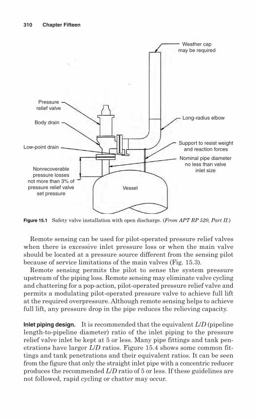
Remote sensing can be used for pilot-operated pressure relief valveswhen there is excessive inlet pressure loss or when the main valveshould be located at a pressure source different from the sensing pilotbecause of service limitations of the main valves (Fig. 15.3).
Remote sensing permits the pilot to sense the system pressureupstream of the piping loss. Remote sensing may eliminate valve cyclingand chattering for a pop-action, pilot-operated pressure relief valve andpermits a modulating pilot-operated pressure valve to achieve full liftat the required overpressure. Although remote sensing helps to achievefull lift, any pressure drop in the pipe reduces the relieving capacity.
Inlet piping design. It is recommended that the equivalent L/D (pipelinelength-to-pipeline diameter) ratio of the inlet piping to the pressurerelief valve inlet be kept at 5 or less. Many pipe fittings and tank pen-etrations have larger L/D ratios. Figure 15.4 shows some common fit-tings and tank penetrations and their equivalent ratios. It can be seenfrom the figure that only the straight inlet pipe with a concentric reducerproduces the recommended L/D ratio of 5 or less. If these guidelines arenot followed, rapid cycling or chatter may occur.
310 Chapter Fifteen
Weather capmay be required
Long-radius elbow
Support to resist weightand reaction forces
Nominal pipe diameterno less than valve
inlet size
Vessel
Pressurerelief valve
Body drain
Low-point drain
Nonrecoverablepressure losses
not more than 3% ofpressure relief valve
set pressure
Figure 15.1 Safety valve installation with open discharge. (From APT RP 520, Part II.)
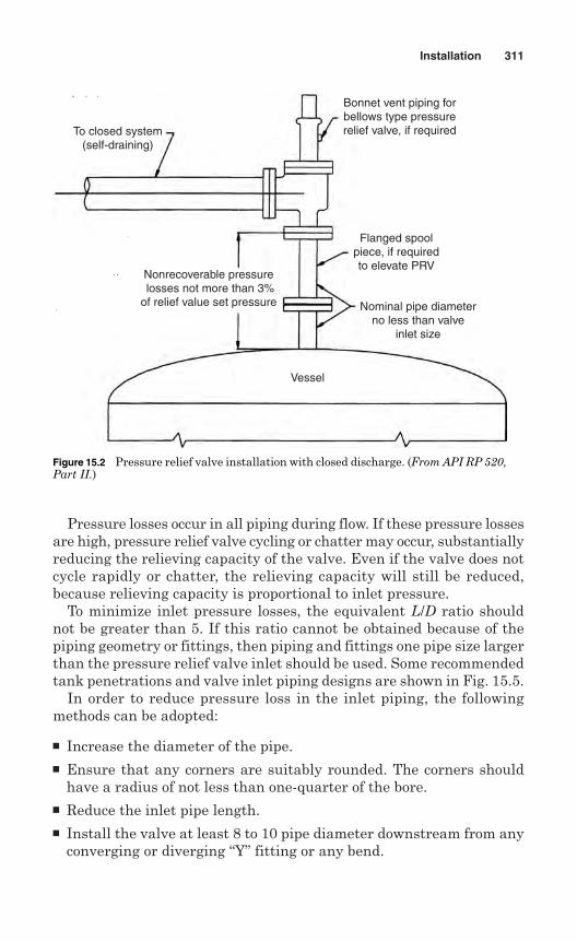
Pressure losses occur in all piping during flow. If these pressure lossesare high, pressure relief valve cycling or chatter may occur, substantiallyreducing the relieving capacity of the valve. Even if the valve does notcycle rapidly or chatter, the relieving capacity will still be reduced,because relieving capacity is proportional to inlet pressure.
To minimize inlet pressure losses, the equivalent L/D ratio shouldnot be greater than 5. If this ratio cannot be obtained because of thepiping geometry or fittings, then piping and fittings one pipe size largerthan the pressure relief valve inlet should be used. Some recommendedtank penetrations and valve inlet piping designs are shown in Fig. 15.5.
In order to reduce pressure loss in the inlet piping, the followingmethods can be adopted:
Increase the diameter of the pipe. Ensure that any corners are suitably rounded. The corners should
have a radius of not less than one-quarter of the bore. Reduce the inlet pipe length. Install the valve at least 8 to 10 pipe diameter downstream from any
converging or diverging “Y” fitting or any bend.
Installation 311
To closed system(self-draining)
Nonrecoverable pressure losses not more than 3%of relief value set pressure
Vessel
Nominal pipe diameterno less than valve
inlet size
Flanged spoolpiece, if requiredto elevate PRV
Bonnet vent piping forbellows type pressurerelief valve, if required
Figure 15.2 Pressure relief valve installation with closed discharge. (From API RP 520,Part II.)
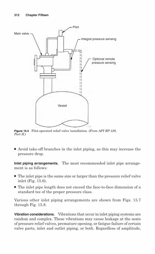
Avoid take-off branches in the inlet piping, as this may increase thepressure drop.
Inlet piping arrangements. The most recommended inlet pipe arrange-ment is as follows:
The inlet pipe is the same size or larger than the pressure relief valveinlet (Fig. 15.6).
The inlet pipe length does not exceed the face-to-face dimension of astandard tee of the proper pressure class.
Various other inlet piping arrangements are shown from Figs. 15.7through Fig. 15.8.
Vibration considerations. Vibrations that occur in inlet piping systems arerandom and complex. These vibrations may cause leakage at the seatsof pressure relief valves, premature opening, or fatigue failure of certainvalve parts, inlet and outlet piping, or both. Regardless of amplitude,
312 Chapter Fifteen
Main valve
Vessel
Optional remotepressure sensing
Integral pressure sensing
Pilot
Figure 15.3 Pilot-operated relief valve installation. (From API RP 520,Part II.)
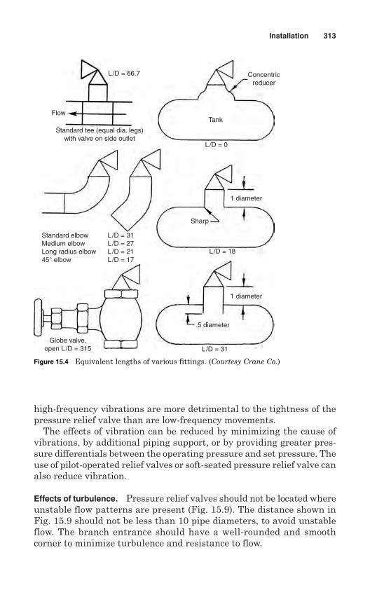
high-frequency vibrations are more detrimental to the tightness of thepressure relief valve than are low-frequency movements.
The effects of vibration can be reduced by minimizing the cause ofvibrations, by additional piping support, or by providing greater pres-sure differentials between the operating pressure and set pressure. Theuse of pilot-operated relief valves or soft-seated pressure relief valve canalso reduce vibration.
Effects of turbulence. Pressure relief valves should not be located whereunstable flow patterns are present (Fig. 15.9). The distance shown inFig. 15.9 should not be less than 10 pipe diameters, to avoid unstableflow. The branch entrance should have a well-rounded and smoothcorner to minimize turbulence and resistance to flow.
Installation 313
Flow
Standard tee (equal dia. legs)with valve on side outlet
L/D = 66.7
L/D = 0
L/D = 18
L/D = 31
Tank
Concentricreducer
1 diameter
1 diameter
Sharp
Standard elbow L/D = 31Medium elbow L/D = 27Long radius elbow L/D = 2145° elbow L/D = 17
Globe valve,open L/D = 315
.5 diameter
Figure 15.4 Equivalent lengths of various fittings. (Courtesy Crane Co.)
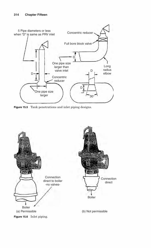
314 Chapter Fifteen
5 Pipe diameters or lesswhen “D” is same as PRV inlet
D
D
D
D
One pipe sizelarger
Concentricreducer
One pipe sizelarger thanvalve inlet
30°
Longradiuselbow
Full bore block valve
Concentric reducer
Figure 15.5 Tank penetrations and inlet piping designs.
Connectiondirect to boiler
-no valves-
Boiler
Boiler
Connectiondirect
(a) Permissible (b) Not permissible
Figure 15.6 Inlet piping.
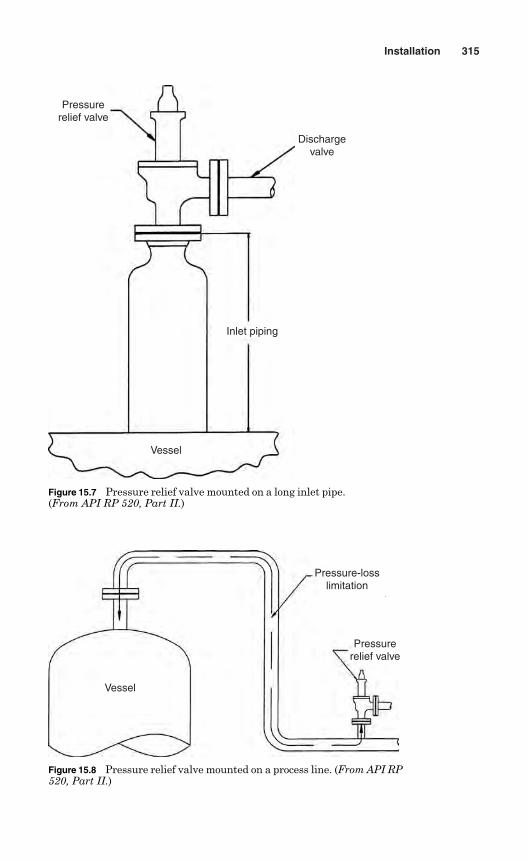
Installation 315
Pressurerelief valve
Dischargevalve
Inlet piping
Vessel
Figure 15.7 Pressure relief valve mounted on a long inlet pipe.(From API RP 520, Part II.)
Pressure-losslimitation
Pressurerelief valve
Vessel
Figure 15.8 Pressure relief valve mounted on a process line. (From API RP520, Part II.)
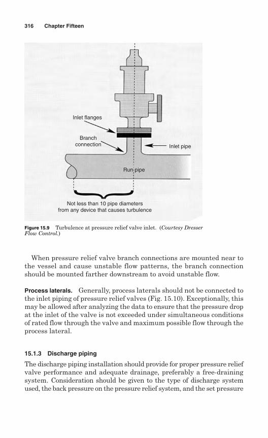
When pressure relief valve branch connections are mounted near tothe vessel and cause unstable flow patterns, the branch connectionshould be mounted farther downstream to avoid unstable flow.
Process laterals. Generally, process laterals should not be connected tothe inlet piping of pressure relief valves (Fig. 15.10). Exceptionally, thismay be allowed after analyzing the data to ensure that the pressure dropat the inlet of the valve is not exceeded under simultaneous conditionsof rated flow through the valve and maximum possible flow through theprocess lateral.
15.1.3 Discharge piping
The discharge piping installation should provide for proper pressure reliefvalve performance and adequate drainage, preferably a free-drainingsystem. Consideration should be given to the type of discharge systemused, the back pressure on the pressure relief system, and the set pressure
316 Chapter Fifteen
Inlet flanges
Branchconnection
Run pipe
Inlet pipe
Not less than 10 pipe diametersfrom any device that causes turbulence
Figure 15.9 Turbulence at pressure relief valve inlet. (Courtesy DresserFlow Control.)
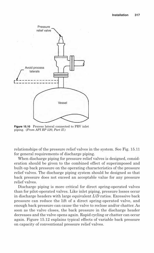
relationships of the pressure relief valves in the system. See Fig. 15.11for general requirements of discharge piping.
When discharge piping for pressure relief valves is designed, consid-eration should be given to the combined effect of superimposed andbuilt-up back pressure on the operating characteristics of the pressurerelief valves. The discharge piping system should be designed so thatback pressure does not exceed an acceptable value for any pressurerelief valves.
Discharge piping is more critical for direct spring-operated valvesthan for pilot-operated valves. Like inlet piping, pressure losses occurin discharge headers with large equivalent L/D ratios. Excessive backpressure can reduce the lift of a direct spring-operated valve, andenough back pressure can cause the valve to reclose and/or chatter. Assoon as the valve closes, the back pressure in the discharge headerdecreases and the valve opens again. Rapid cycling or chatter can occuragain. Figure 15.12 explains typical effects of variable back pressureon capacity of conventional pressure relief valves.
Installation 317
Pressurerelief valve
Avoid processlaterals
Vessel
Figure 15.10 Process lateral connected to PRV inletpiping. (From API RP 520, Part II.)
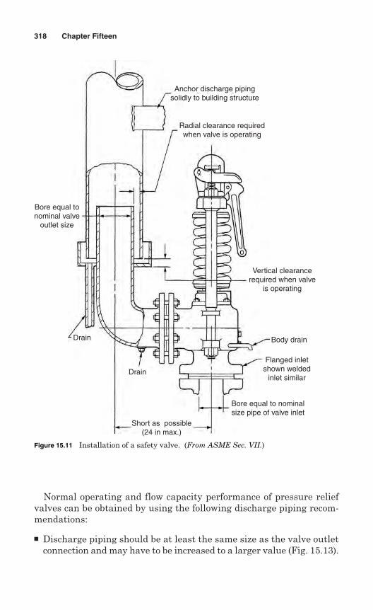
Normal operating and flow capacity performance of pressure reliefvalves can be obtained by using the following discharge piping recom-mendations:
Discharge piping should be at least the same size as the valve outletconnection and may have to be increased to a larger value (Fig. 15.13).
318 Chapter Fifteen
Anchor discharge pipingsolidly to building structure
Radial clearance requiredwhen valve is operating
Vertical clearancerequired when valve
is operating
Body drain
Flanged inletshown welded
inlet similar
Bore equal to nominalsize pipe of valve inlet
Short as possible(24 in max.)
Drain
Drain
Bore equal tonominal valve
outlet size
Figure 15.11 Installation of a safety valve. (From ASME Sec. VII.)
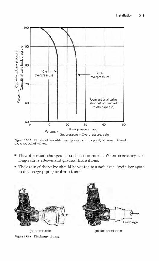
Flow direction changes should be minimized. When necessary, uselong-radius elbows and gradual transitions.
The drain of the valve should be vented to a safe area. Avoid low spotsin discharge piping or drain them.
Installation 319
100
90
80
70
60
500 10 20 30 40 50
Cap
acity
at b
ack
pres
sure
Cap
acity
at z
ero
back
pre
ssur
eP
erce
nt =
Back pressure, psig
Set pressure + Overpressure, psigPercent =
10%overpressure
20%overpressure
Conventional valve(bonnet not vented
to atmosphere)
Figure 15.12 Effects of variable back pressure on capacity of conventionalpressure relief valves.
(a) Permissible (b) Not permissible
Discharge
Figure 15.13 Discharge piping.
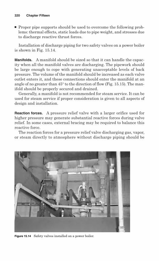
Proper pipe supports should be used to overcome the following prob-lems: thermal effects, static loads due to pipe weight, and stresses dueto discharge reactive thrust forces.
Installation of discharge piping for two safety valves on a power boileris shown in Fig. 15.14.
Manifolds. A manifold should be sized so that it can handle the capac-ity when all the manifold valves are discharging. The pipework shouldbe large enough to cope with generating unacceptable levels of backpressure. The volume of the manifold should be increased as each valveoutlet enters it, and these connections should enter the manifold at anangle of no greater than 45° to the direction of flow (Fig. 15.15). The man-ifold should be properly secured and drained.
Generally, a manifold is not recommended for steam service. It can beused for steam service if proper consideration is given to all aspects ofdesign and installation.
Reaction forces. A pressure relief valve with a larger orifice used forhigher pressure may generate substantial reactive forces during valverelief. In some cases, external bracing may be required to balance thisreactive force.
The reaction forces for a pressure relief valve discharging gas, vapor,or steam directly to atmosphere without discharge piping should be
320 Chapter Fifteen
Figure 15.14 Safety valves installed on a power boiler.
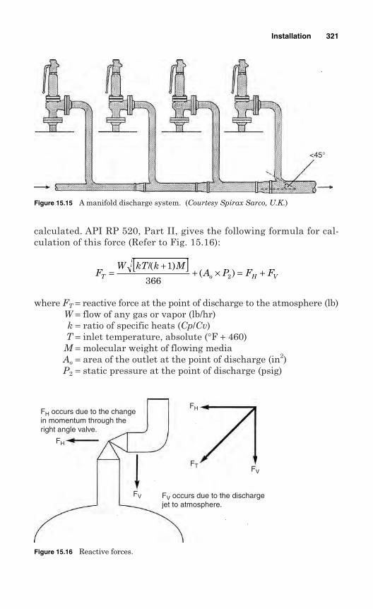
calculated. API RP 520, Part II, gives the following formula for cal-culation of this force (Refer to Fig. 15.16):
where FT = reactive force at the point of discharge to the atmosphere (lb)W = flow of any gas or vapor (lb/hr)k = ratio of specific heats (Cp/Cv)T = inlet temperature, absolute (°F + 460)M = molecular weight of flowing mediaAo = area of the outlet at the point of discharge (in2)P2 = static pressure at the point of discharge (psig)
FW kT k M
A P F FT o H V=+[ ]
+ × = +/( )
( )1
366 2
Installation 321
<45°
Figure 15.15 A manifold discharge system. (Courtesy Spirax Sarco, U.K.)
FH occurs due to the changein momentum through theright angle valve.
FH
FV
FH
FT FV
FV occurs due to the dischargejet to atmosphere.
Figure 15.16 Reactive forces.
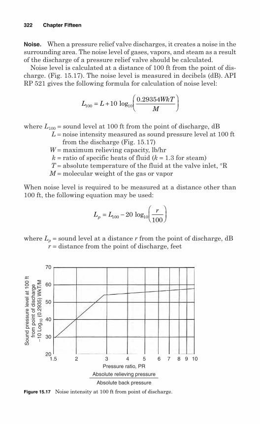
Noise. When a pressure relief valve discharges, it creates a noise in thesurrounding area. The noise level of gases, vapors, and steam as a resultof the discharge of a pressure relief valve should be calculated.
Noise level is calculated at a distance of 100 ft from the point of dis-charge. (Fig. 15.17). The noise level is measured in decibels (dB). APIRP 521 gives the following formula for calculation of noise level:
where L100 = sound level at 100 ft from the point of discharge, dBL = noise intensity measured as sound pressure level at 100 ft
from the discharge (Fig. 15.17)W = maximum relieving capacity, lb/hrk = ratio of specific heats of fluid (k = 1.3 for steam)T = absolute temperature of the fluid at the valve inlet, °RM = molecular weight of the gas or vapor
When noise level is required to be measured at a distance other than100 ft, the following equation may be used:
where Lp = sound level at a distance r from the point of discharge, dBr = distance from the point of discharge, feet
L Lr
p = −
100 20
100 log10
L LWkT
M100 100 29354= +
log10
.
322 Chapter Fifteen
20
30
40
50
60
70
1.5 2 3 4 5 6 7 8 9 10Pressure ratio, PR
Absolute relieving pressure
Absolute back pressure
Sou
nd p
ress
ure
leve
l at 1
00 ft
from
poi
nt o
f dis
char
ge−1
0 Lo
g 10
(0.2
935)
WkT
/M
Figure 15.17 Noise intensity at 100 ft from point of discharge.
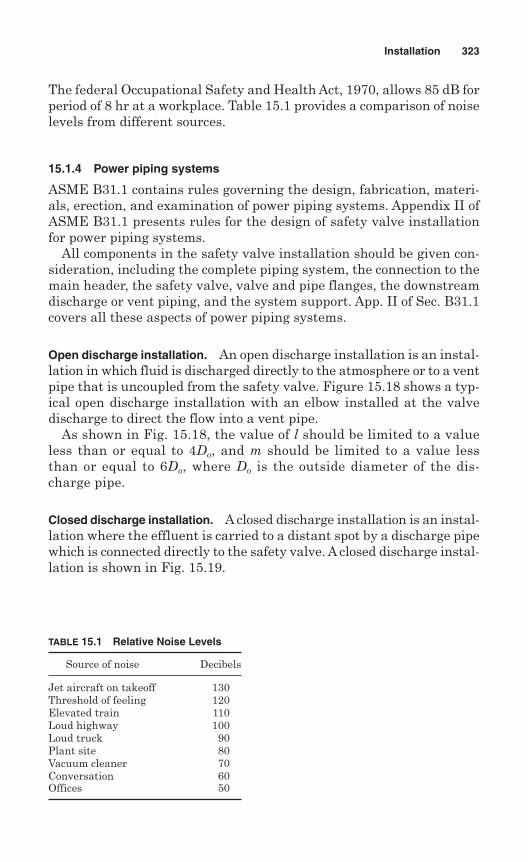
The federal Occupational Safety and Health Act, 1970, allows 85 dB forperiod of 8 hr at a workplace. Table 15.1 provides a comparison of noiselevels from different sources.
15.1.4 Power piping systems
ASME B31.1 contains rules governing the design, fabrication, materi-als, erection, and examination of power piping systems. Appendix II ofASME B31.1 presents rules for the design of safety valve installationfor power piping systems.
All components in the safety valve installation should be given con-sideration, including the complete piping system, the connection to themain header, the safety valve, valve and pipe flanges, the downstreamdischarge or vent piping, and the system support. App. II of Sec. B31.1covers all these aspects of power piping systems.
Open discharge installation. An open discharge installation is an instal-lation in which fluid is discharged directly to the atmosphere or to a ventpipe that is uncoupled from the safety valve. Figure 15.18 shows a typ-ical open discharge installation with an elbow installed at the valvedischarge to direct the flow into a vent pipe.
As shown in Fig. 15.18, the value of l should be limited to a valueless than or equal to 4Do, and m should be limited to a value lessthan or equal to 6Do, where Do is the outside diameter of the dis-charge pipe.
Closed discharge installation. A closed discharge installation is an instal-lation where the effluent is carried to a distant spot by a discharge pipewhich is connected directly to the safety valve. A closed discharge instal-lation is shown in Fig. 15.19.
Installation 323
TABLE 15.1 Relative Noise Levels
Source of noise Decibels
Jet aircraft on takeoff 130Threshold of feeling 120Elevated train 110Loud highway 100Loud truck 90Plant site 80Vacuum cleaner 70Conversation 60Offices 50
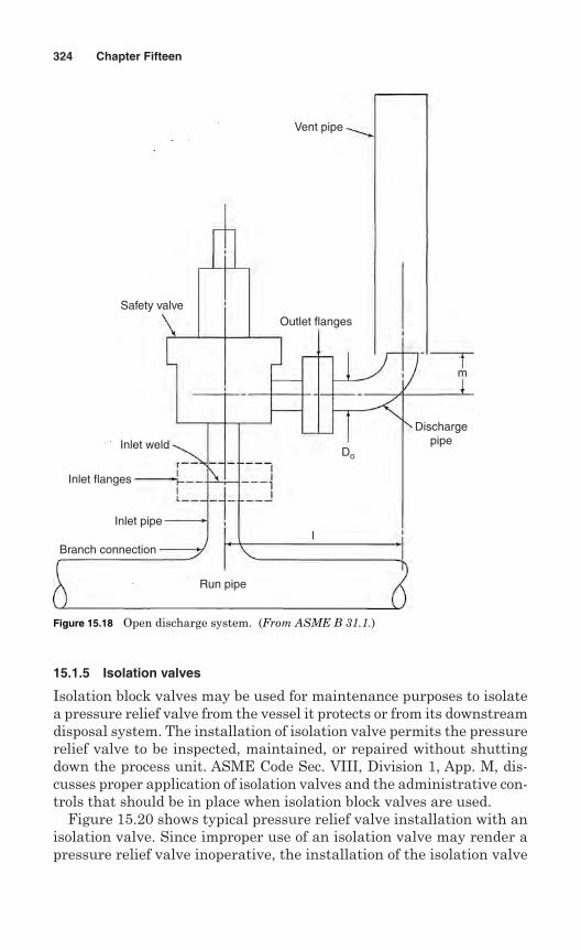
15.1.5 Isolation valves
Isolation block valves may be used for maintenance purposes to isolatea pressure relief valve from the vessel it protects or from its downstreamdisposal system. The installation of isolation valve permits the pressurerelief valve to be inspected, maintained, or repaired without shuttingdown the process unit. ASME Code Sec. VIII, Division 1, App. M, dis-cusses proper application of isolation valves and the administrative con-trols that should be in place when isolation block valves are used.
Figure 15.20 shows typical pressure relief valve installation with anisolation valve. Since improper use of an isolation valve may render apressure relief valve inoperative, the installation of the isolation valve
324 Chapter Fifteen
Vent pipe
Branch connection
Inlet pipe
Inlet flanges
Inlet weld
Safety valve
Run pipe
Outlet flanges
Dischargepipe
m
Do
l
Figure 15.18 Open discharge system. (From ASME B 31.1.)
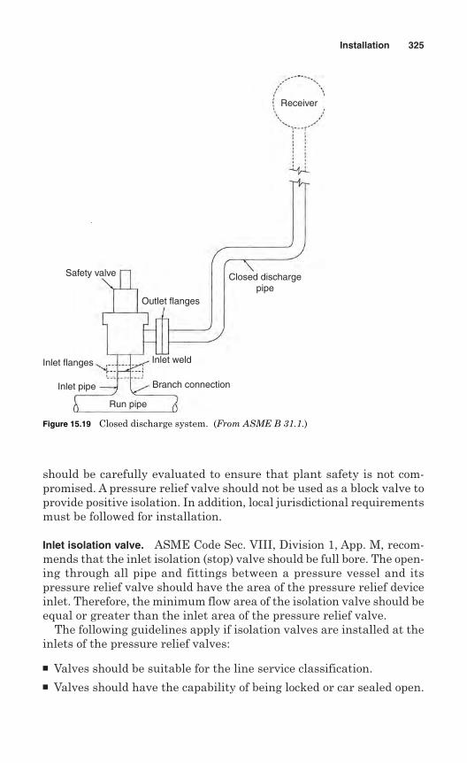
should be carefully evaluated to ensure that plant safety is not com-promised. A pressure relief valve should not be used as a block valve toprovide positive isolation. In addition, local jurisdictional requirementsmust be followed for installation.
Inlet isolation valve. ASME Code Sec. VIII, Division 1, App. M, recom-mends that the inlet isolation (stop) valve should be full bore. The open-ing through all pipe and fittings between a pressure vessel and itspressure relief valve should have the area of the pressure relief deviceinlet. Therefore, the minimum flow area of the isolation valve should beequal or greater than the inlet area of the pressure relief valve.
The following guidelines apply if isolation valves are installed at theinlets of the pressure relief valves:
Valves should be suitable for the line service classification. Valves should have the capability of being locked or car sealed open.
Installation 325
Receiver
Closed dischargepipe
Outlet flanges
Safety valve
Inlet weld
Run pipe
Branch connection
Inlet flanges
Inlet pipe
Figure 15.19 Closed discharge system. (From ASME B 31.1.)
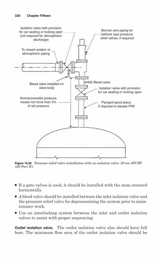
If a gate valves is used, it should be installed with the stem orientedhorizontally.
A bleed valve should be installed between the inlet isolation valve andthe pressure relief valve for depressurizing the system prior to main-tenance work.
Use an interlocking system between the inlet and outlet isolationvalves to assist with proper sequencing.
Outlet isolation valve. The outlet isolation valve also should have fullbore. The minimum flow area of the outlet isolation valve should be
326 Chapter Fifteen
Nonrecoverable pressurelosses not more than 3%
of set pressure
Bleed valve installed onvalve body
Flanged spool piece,if required to elevate PRV
Isolation valve with provisionfor car sealing or locking open
Bleed valve
Bonnet vent piping forbellows type pressure
relief valves, if required
Isolation valve with provisionfor car sealing or locking open(not required for atmospheric
discharge)
To closed system oratmospheric piping
Figure 15.20 Pressure relief valve installation with an isolation valve. (From API RP520 Part II.)
equal to or greater than the outlet area of the pressure relief valve.When the outlet isolation valve is used in conjunction with an inletisolation valve, the outlet isolation valve should be opened fully priorto the inlet isolation valve.
The following guidelines apply if isolation valves are installed at theoutlets of pressure relief valves:
Valves should be suitable for the line service classification. Valves should have the capability of being locked or car sealed open. A bleed valve should be installed between the outlet isolation valve
and the pressure relief valve for depressurizing the system prior tomaintenance work.
15.1.6 Vent piping
Based on the type of pressure relief valve, proper ventilating of the bon-nets and pilots is required to ensure proper operation of the valve.
Bonnets on conventional pressure relief valves do not have anyspecial venting requirements. Open bonnets are normally used insteam service and are exposed directly to the atmosphere. Valveswith closed bonnets are internally vented to the pressure relief valvedischarge.
Pilots are often vented to the atmosphere under operating condi-tions, as the discharge during operation is small. When vent dischargeto the atmosphere is not allowed, the pilot should be vented either tothe discharge piping or through a supplementary piping system to asafe location.
15.1.7 Drain piping
It is recommended that the discharge piping from pressure relief valvesbe drained properly to prevent the accumulation of liquids on the down-stream side of the pressure relief valve. The outlet piping to closed sys-tems should be self-draining to a liquid disposal point. If the dischargepiping is not self-draining and the valve is located where liquids couldaccumulate at the outlet, drain piping should be provided. The drainpiping can be installed on the discharge piping or at the valve in the bodyconnection provided for this purpose.
As drain piping is a part of the entire ventilating system, precautionsthat apply to the discharge system are also applicable for the drain piping.The drain piping installation should not affect the valve performance. Itis reminded that flammable, toxic, or corrosive fluids be piped to a safelocation.
Installation 327
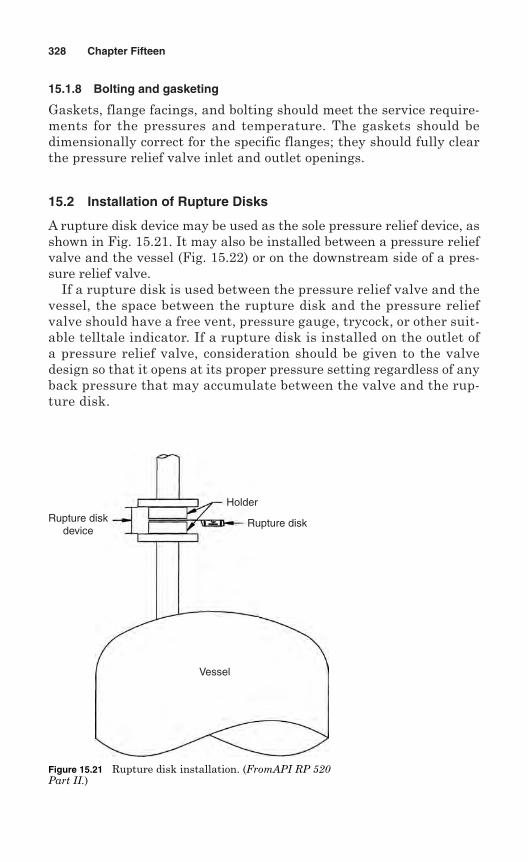
15.1.8 Bolting and gasketing
Gaskets, flange facings, and bolting should meet the service require-ments for the pressures and temperature. The gaskets should bedimensionally correct for the specific flanges; they should fully clearthe pressure relief valve inlet and outlet openings.
15.2 Installation of Rupture Disks
A rupture disk device may be used as the sole pressure relief device, asshown in Fig. 15.21. It may also be installed between a pressure reliefvalve and the vessel (Fig. 15.22) or on the downstream side of a pres-sure relief valve.
If a rupture disk is used between the pressure relief valve and thevessel, the space between the rupture disk and the pressure reliefvalve should have a free vent, pressure gauge, trycock, or other suit-able telltale indicator. If a rupture disk is installed on the outlet ofa pressure relief valve, consideration should be given to the valvedesign so that it opens at its proper pressure setting regardless of anyback pressure that may accumulate between the valve and the rup-ture disk.
328 Chapter Fifteen
Rupture diskdevice
Holder
Rupture disk
Vessel
Figure 15.21 Rupture disk installation. (FromAPI RP 520Part II.)
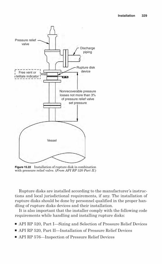
Rupture disks are installed according to the manufacturer’s instruc-tions and local jurisdictional requirements, if any. The installation ofrupture disks should be done by personnel qualified in the proper han-dling of rupture disks devices and their installation.
It is also important that the installer comply with the following coderequirements while handling and installing rupture disks:
API RP 520, Part I—Sizing and Selection of Pressure Relief Devices API RP 520, Part II—Installation of Pressure Relief Devices API RP 576—Inspection of Pressure Relief Devices
Installation 329
Pressure reliefvalve
Free vent ortelitale indicator
Dischargepiping
Rupture diskdevice
Nonrecoverable pressurelosses not more than 3%of pressure relief valve
set pressure
Vessel
Figure 15.22 Installation of rupture disk in combinationwith pressure relief valve. (From API RP 520 Part II.)
15.2.1 Preparation for installation
The installing contractor should make necessary preparations prior toinstallation of rupture disks. The following items should be checked:
1. Holder and flange sizes and rating are the same.
2. Companion flanges area. Undamagedb. Clean and free of debris, gasket residue, and corrosionc. Parallel and aligned
3. Selected gaskets should seal at the recommended torque.
4. Generally, rupture disks are provided with shipping protectors orsupports. Remove such shipping protectors and supports prior toinstallation.
5. Make sure that the rupture disk type is appropriate for the holder.Also, ensure that the rupture disk type has been selected based onburst pressure, temperature, material, etc., for the application.
6. Proper tools should be used for installation. The flange ends andnuts should be clean.
15.5.2 Inspection
All rupture disks should be thoroughly inspected before installation. Themanufacturer’s instructions must be followed with respect to the rup-ture disk. The following points should be noted:
The seating surfaces should be clean, smooth, and undamaged. The disks should be checked for physical damage to the seating sur-
face or the prebulged disk area. Damaged or dented disks should not be used. The safety heads of bolted construction should be checked for proper
torque as recommended by the manufacturer. The knife blades on reverse buckling disks should be checked for
physical damage. Nicked or dull blades should not be used.
15.2.3 Installation guidelines
The contractor installing rupture disks should take all precautions forcorrect installation. The manufacturer’s instructions should be followedfor such precautions. The following guidelines should be practiced forinstallation:
1. Make sure that the rupture disk vents to a safe area.
2. Assemble the disk and holder in shop, if possible.
330 Chapter Fifteen

3. Keep the rupture disk in the original packing until ready for instal-lation.
4. Look for flow arrows on the disks. Verify correct orientation of diskin holder and of holder in piping.
5. Follow manufacturer’s instructions for proper torque and tighteningsequences.
6. Verify that the application is designed in such a way that fluid accu-mulation on the downstream side of a rupture disk device cannotinfluence and elevate the rated pressure of the disk.
Installation 331

This page intentionally left blank
Chapter
Operation
Many pressure relief devices never operate except during a test. The equip-ment operator or operating engineer must ensure that pressure reliefdevices are in operating condition by testing the devices from time to time.
Pressure relief valves are designed to function based on the relation-ship of a number of critically dimensioned parts and the valve spring.These relationships determine the force geometry necessary for reli-able operation.
The owner has the responsibility to establish and maintain a systemthat ensures that a vessel is not operated without overpressure protec-tion. These responsibilities include, but are not limited to, the following:
Establish the pressure relief philosophy and the administrative con-trol requirements.
Establish procedures to ensure that equipment is adequately pro-tected against overpressure.
Ensure that authorization to operate identified valves is clear and thatpersonnel are adequately trained for this task.
Establish the analysis procedures and basis to be used in determin-ing the potential level of pressure if the stop valves are closed.
16.1 General Guidelines for Operation
Due to the variety of service conditions and the various designs of safetyand safety relief valves, only general guidelines can be given regardingoperation. App. M of Section VIII—Div. 1 may be used as nonmanda-tory guidelines for pressure relief valve operation.
The following general advisory information should be reviewed andthen used for a specific application:
333
16
Copyright © 2006 by The McGraw-Hill Companies, Inc. Click here for terms of use.
1. Leakage may be observed when there is dirt or scale sitting on theseating face. This usually occurs during the periodic lifting requiredby the authorized inspector or routine maintenance personnel.Further lifting of the lever will generally clear any dirt that mighthave been on the seating surface.
2. The vast majority of safety valve leakage occurs after initial man-ufacture and test. The problem may result from damage duringshipping or transportation. Other reasons are mishandling, con-tamination, or poor installation.
3. Most safety valve standards do not include detailed shut-offparameters. Recommended test procedures as specified in API-527are commonly used throughout the safety valve industry.
4. The test procedures for valves that have been set on air involveblocking all secondary leakage paths while maintaining the valve at90% of the set pressure on air. The outlet of the valve is connectedto a 6-mm-ID pipe, the end of which is held 12.7 mm below the sur-face of water contained in a transparent vessel. The number of bub-bles discharged from this tube should be 20 bubbles per minute.
5. For valves set on steam or water, the leakage rate should be assessedusing the corresponding setting medium. For steam, there shouldnot be any visible leakage against a black background for 1 min aftera 3-min stabilization period. For water, a small leakage is allowed,depending on the orifice area, of 10 mL/hr per inch of nominal inletdiameter.
6. A test using accurate flow-measuring equipment that is calibratedin accordance with the requirements of API 527 may be used insteadof the above test procedures.
7. Neither should additional load be applied to the easing lever norshould the valve be gagged in order to increase the seat tightness.This may affect the operating characteristics and result in the safetyvalve failing to lift in overpressure conditions.
8. If there is heavy seat leakage, the valve can be refurbished orrepaired, but only by an authorized repairer, working with approvalfrom the original equipment manufacturer (OEM), and using infor-mation supplied by the manufacturer.
9. The valve should be sent to repair if any repair is necessary. Anauthorized repair company should repair the valve using informa-tion supplied by the original equipment manufacturer.
10. The safety valve should not be used as a control valve to regulatesystem operating pressure. Excessive operation will cause the seatto leak and require more frequent valve maintenance.
334 Chapter Sixteen
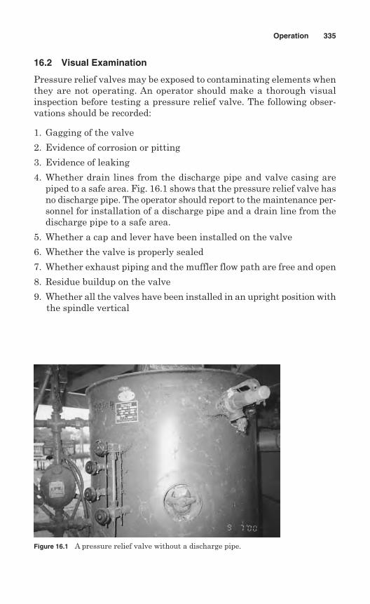
16.2 Visual Examination
Pressure relief valves may be exposed to contaminating elements whenthey are not operating. An operator should make a thorough visualinspection before testing a pressure relief valve. The following obser-vations should be recorded:
1. Gagging of the valve
2. Evidence of corrosion or pitting
3. Evidence of leaking
4. Whether drain lines from the discharge pipe and valve casing arepiped to a safe area. Fig. 16.1 shows that the pressure relief valve hasno discharge pipe. The operator should report to the maintenance per-sonnel for installation of a discharge pipe and a drain line from thedischarge pipe to a safe area.
5. Whether a cap and lever have been installed on the valve
6. Whether the valve is properly sealed
7. Whether exhaust piping and the muffler flow path are free and open
8. Residue buildup on the valve
9. Whether all the valves have been installed in an upright position withthe spindle vertical
Operation 335
Figure 16.1 A pressure relief valve without a discharge pipe.
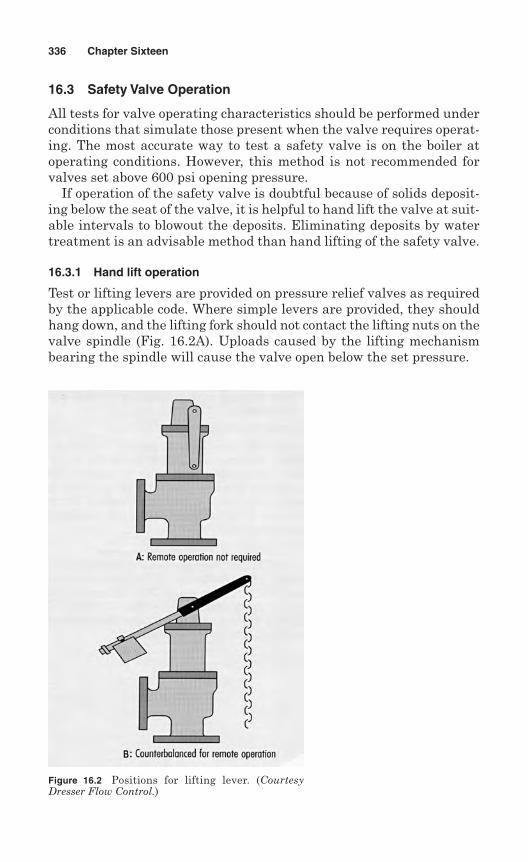
16.3 Safety Valve Operation
All tests for valve operating characteristics should be performed underconditions that simulate those present when the valve requires operat-ing. The most accurate way to test a safety valve is on the boiler atoperating conditions. However, this method is not recommended forvalves set above 600 psi opening pressure.
If operation of the safety valve is doubtful because of solids deposit-ing below the seat of the valve, it is helpful to hand lift the valve at suit-able intervals to blowout the deposits. Eliminating deposits by watertreatment is an advisable method than hand lifting of the safety valve.
16.3.1 Hand lift operation
Test or lifting levers are provided on pressure relief valves as requiredby the applicable code. Where simple levers are provided, they shouldhang down, and the lifting fork should not contact the lifting nuts on thevalve spindle (Fig. 16.2A). Uploads caused by the lifting mechanismbearing the spindle will cause the valve open below the set pressure.
336 Chapter Sixteen
Figure 16.2 Positions for lifting lever. (CourtesyDresser Flow Control.)
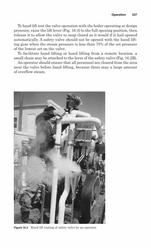
To hand lift test the valve operation with the boiler operating at designpressure, raise the lift lever (Fig. 16.3) to the full opening position, thenrelease it to allow the valve to snap closed as it would if it had openedautomatically. A safety valve should not be opened with the hand lift-ing gear when the steam pressure is less than 75% of the set pressureof the lowest set on the valve.
To facilitate hand lifting or hand lifting from a remote location, asmall chain may be attached to the lever of the safety valve (Fig. 16.2B).
An operator should ensure that all personnel are cleared from the areanear the valve before hand lifting, because there may a large amountof overflow steam.
Operation 337
Figure 16.3 Hand lift testing of safety valve by an operator.
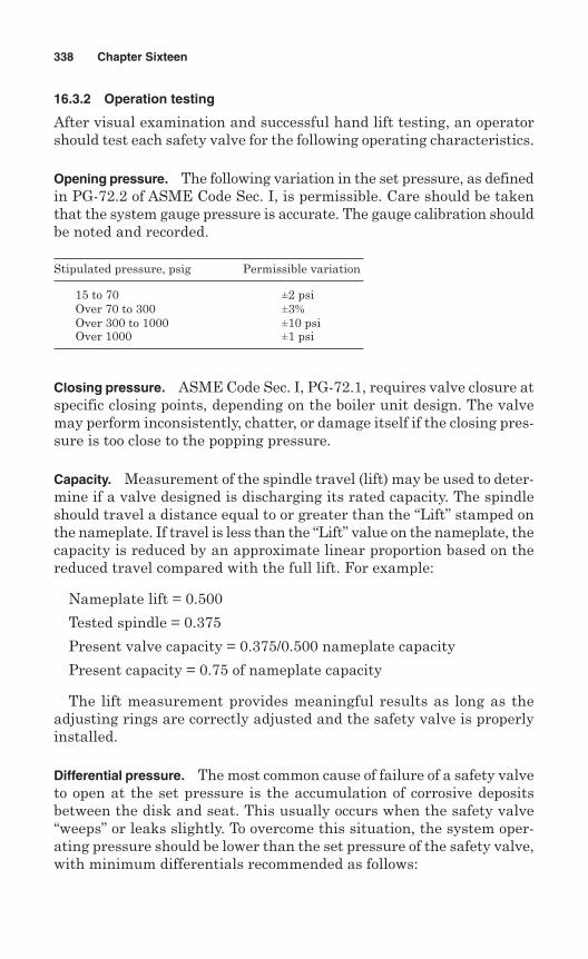
16.3.2 Operation testing
After visual examination and successful hand lift testing, an operatorshould test each safety valve for the following operating characteristics.
Opening pressure. The following variation in the set pressure, as definedin PG-72.2 of ASME Code Sec. I, is permissible. Care should be takenthat the system gauge pressure is accurate. The gauge calibration shouldbe noted and recorded.
Stipulated pressure, psig Permissible variation
15 to 70 ±2 psiOver 70 to 300 ±3%Over 300 to 1000 ±10 psiOver 1000 ±1 psi
Closing pressure. ASME Code Sec. I, PG-72.1, requires valve closure atspecific closing points, depending on the boiler unit design. The valvemay perform inconsistently, chatter, or damage itself if the closing pres-sure is too close to the popping pressure.
Capacity. Measurement of the spindle travel (lift) may be used to deter-mine if a valve designed is discharging its rated capacity. The spindleshould travel a distance equal to or greater than the “Lift” stamped onthe nameplate. If travel is less than the “Lift” value on the nameplate, thecapacity is reduced by an approximate linear proportion based on thereduced travel compared with the full lift. For example:
Nameplate lift = 0.500
Tested spindle = 0.375
Present valve capacity = 0.375/0.500 nameplate capacity
Present capacity = 0.75 of nameplate capacity
The lift measurement provides meaningful results as long as theadjusting rings are correctly adjusted and the safety valve is properlyinstalled.
Differential pressure. The most common cause of failure of a safety valveto open at the set pressure is the accumulation of corrosive depositsbetween the disk and seat. This usually occurs when the safety valve“weeps” or leaks slightly. To overcome this situation, the system oper-ating pressure should be lower than the set pressure of the safety valve,with minimum differentials recommended as follows:
338 Chapter Sixteen
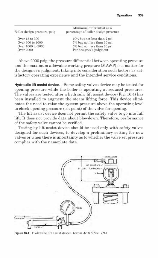
Minimum differential as aBoiler design pressure, psig percentage of boiler design pressure
Over 15 to 300 10% but not less than 7 psiOver 300 to 1000 7% but not less than 30 psiOver 1000 to 2000 5% but not less than 70 psiOver 2000 Per designer’s judgment
Above 2000 psig, the pressure differential between operating pressureand the maximum allowable working pressure (MAWP) is a matter forthe designer’s judgment, taking into consideration such factors as sat-isfactory operating experience and the intended service conditions.
Hydraulic lift assist device. Some safety valves device may be tested foropening pressure while the boiler is operating at reduced pressures.The valves are tested after a hydraulic lift assist device (Fig. 16.4) hasbeen installed to augment the steam lifting force. This device elimi-nates the need to raise the system pressure above the operating levelto check opening pressure (set point) of the valve for opening.
The lift assist device does not permit the safety valve to go into fulllift. It does not provide data about blowdown. Therefore, performanceof the safety valve cannot be verified.
Testing by lift assist device should be used only with safety valvesdesigned for such devices, to develop a preliminary setting for newvalves or when there is uncertainty as to whether the valve set pressurecomplies with the nameplate data.
Operation 339
Figure 16.4 Hydraulic lift assist device. (From ASME Sec. VII.)
Pump
Gage
13–1/2 in.
Lift assist unit
Turnbuckle
Yoke
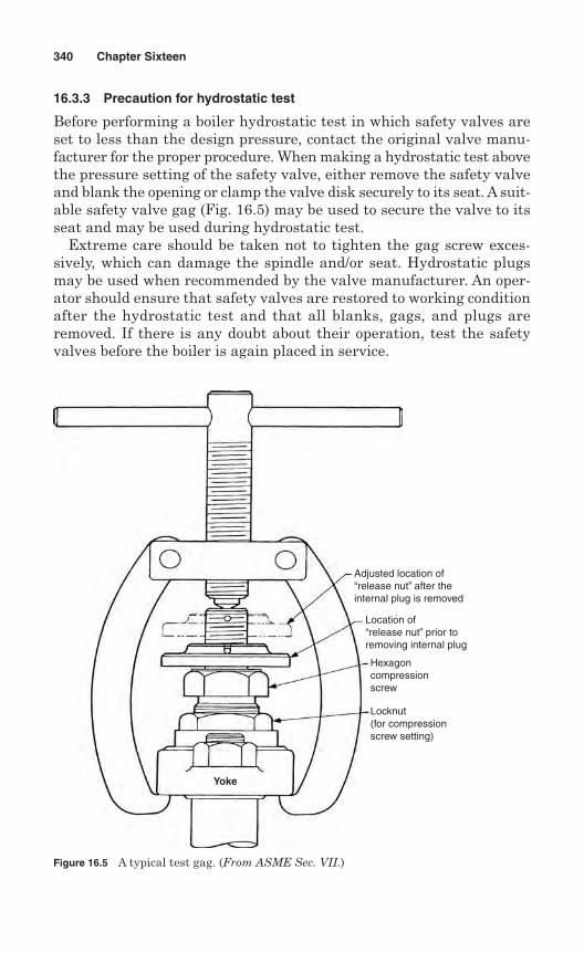
16.3.3 Precaution for hydrostatic test
Before performing a boiler hydrostatic test in which safety valves areset to less than the design pressure, contact the original valve manu-facturer for the proper procedure. When making a hydrostatic test abovethe pressure setting of the safety valve, either remove the safety valveand blank the opening or clamp the valve disk securely to its seat. A suit-able safety valve gag (Fig. 16.5) may be used to secure the valve to itsseat and may be used during hydrostatic test.
Extreme care should be taken not to tighten the gag screw exces-sively, which can damage the spindle and/or seat. Hydrostatic plugsmay be used when recommended by the valve manufacturer. An oper-ator should ensure that safety valves are restored to working conditionafter the hydrostatic test and that all blanks, gags, and plugs areremoved. If there is any doubt about their operation, test the safetyvalves before the boiler is again placed in service.
340 Chapter Sixteen
Figure 16.5 A typical test gag. (From ASME Sec. VII.)
Adjusted location of“release nut” after theinternal plug is removed
Location of“release nut” prior toremoving internal plug
Hexagoncompressionscrew
Locknut(for compressionscrew setting)
Yoke
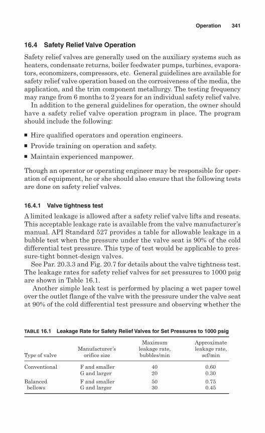
16.4 Safety Relief Valve Operation
Safety relief valves are generally used on the auxiliary systems such asheaters, condensate returns, boiler feedwater pumps, turbines, evapora-tors, economizers, compressors, etc. General guidelines are available forsafety relief valve operation based on the corrosiveness of the media, theapplication, and the trim component metallurgy. The testing frequencymay range from 6 months to 2 years for an individual safety relief valve.
In addition to the general guidelines for operation, the owner shouldhave a safety relief valve operation program in place. The programshould include the following:
Hire qualified operators and operation engineers. Provide training on operation and safety. Maintain experienced manpower.
Though an operator or operating engineer may be responsible for oper-ation of equipment, he or she should also ensure that the following testsare done on safety relief valves.
16.4.1 Valve tightness test
A limited leakage is allowed after a safety relief valve lifts and reseats.This acceptable leakage rate is available from the valve manufacturer’smanual. API Standard 527 provides a table for allowable leakage in abubble test when the pressure under the valve seat is 90% of the colddifferential test pressure. This type of test would be applicable to pres-sure-tight bonnet-design valves.
See Par. 20.3.3 and Fig. 20.7 for details about the valve tightness test.The leakage rates for safety relief valves for set pressures to 1000 psigare shown in Table 16.1.
Another simple leak test is performed by placing a wet paper towelover the outlet flange of the valve with the pressure under the valve seatat 90% of the cold differential test pressure and observing whether the
Operation 341
TABLE 16.1 Leakage Rate for Safety Relief Valves for Set Pressures to 1000 psig
Maximum ApproximateManufacturer’s leakage rate, leakage rate,
Type of valve orifice size bubbles/min scf/min
Conventional F and smaller 40 0.60G and larger 20 0.30
Balanced F and smaller 50 0.75bellows G and larger 30 0.45
towel ruptures. This test is used to verify tightness in noncritical appli-cations. The wet paper towel test is applicable to pressure-tight bonnet-design valves only.
A cold rod test is used to detect seat leakage for exposed spring ornonpressure-tight bonnet-design valves in steam service. This test isperformed by removing the valve discharge pipe and placing a cold rodnear the valve seat. The formation of condensate on the rod indicatesvalve leakage.
16.4.2 Lift and blowdown
Lift is a very important characteristic, as full relieving capacity of thevalve can only be achieved at full rated lift. Blowdown is the differencebetween the set pressure and the closing pressure of the valve.
The system operating pressure should be below the valve closing pres-sure. Blowdown is a meaningful characteristic for gas, steam, or airapplications.
16.4.3 Testing
A safety relief valve should be tested after any maintenance work. Thistesting can be performed on a test stand designed for compressed air (forair or gas applications) or pressurized water (for liquid applications).
Atest stand can verify the quality of workmanship for all functions. Thecapacity of the test stand determines the maximum size of the valve thatcan be lift and blowdown tested. See Chap. 20 for details of valve testing.
All valves should be sealed after testing to ensure that no furtheradjustments are made. Testing of the safety relief valve should be per-formed by qualified personnel.
16.5 Operator’s Responsibilities
An operator is responsible for safe operation of equipment, includingpressure relief devices. Though an operator’s principal job is to operatethe main equipment, his or her responsibilities relating to pressurerelief devices might include the following:
Initiating work requests Overseeing that devices are reinstalled in their proper locations Preparing in-service reports Checking for leaking pressure relief devices Making sure that the correct block valves are locked or sealed open
or closed as required. Checking vents and drains for operability
342 Chapter Sixteen
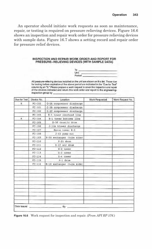
An operator should initiate work requests as soon as maintenance,repair, or testing is required on pressure relieving devices. Figure 16.6shows an inspection and repair work order for pressure relieving deviceswith sample data. Figure 16.7 shows a setting record and repair orderfor pressure relief devices.
Operation 343
Figure 16.6 Work request for inspection and repair. (From API RP 576.)
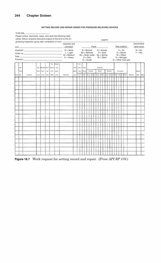
344 Chapter Sixteen
Reliev.- Dis.
ing
pres-
sure
Test
Med-
Vavle
Stuck
Deposits
Nozzle Body Bonnet Corrosion Repair
man-
tled
ium N N N N N NH H H Part Repaire Man DateH M M MM L L LLY YRemarks
No.
Notch
D.D.
Ring
Set
Pres-
sure
De-
vice
No. LocationSize
Reseat
Pres-
sure
Bon-
net
test
SETTING RECORD AND REPAIR ORDER FOR PRESSURE-RELIEVING DEVICES
To Mr./Ms. Please relieve, dismantle, repair, and reset the following reliefvalves. Return properly executed original of this form to the en-gineering-inspection group after completion of work.
Unit
Foreman
Date
Order no.
Inspector
Deposits andcorrosion Parts Test medium
Legend
H = HeavyM = Medium
L = LightN = None
St = StemSp = Spring
S = SeatN = Nozzle
D = DiskG = Guide
Bo = Body outletBe = BellowsB = Bonnet
N = NitrogenO = Other inert gas
W = WaterS = Steam
A = Air
Dismantled/valve stuck
Y = YesN = No
:
Figure 16.7 Work request for setting record and repair. (From API RP 576.)
Chapter
Maintenance
The functioning and service life of a pressure relief valve depends prima-rily on regular maintenance. Pressure relief valves can provide long peri-ods of trouble-free service if proper maintenance is done when necessary.
Maintenance on pressure relief valves should be done by personnelqualified and experienced in handling, maintenance, and repair ofvalves. Maintenance personnel require special training and experienceto work with pressure relief valves.
A pressure relief valve maintenance program should be developed toensure the following valve operating characteristics:
Opens at the set pressure Closes at the proper pressure Rated lift is achieved
The above information is available from the pressure relief valvenameplate. If the nameplate is missing or nameplate information cannot be read, a duplicate nameplate should be ordered from the originalvalve manufacturer. The duplicate nameplate should be installed afterobtaining approval from the jurisdiction.
The maintenance of pressure relief devices should be done by experi-enced mechanics under the supervision of a maintenance engineer.Duties and responsibilities of maintenance mechanics should be clearlydefined to avoid confusion. The responsibilities of maintenance mechan-ics might include the following:
To perform mechanical work required to install, test, reinstall, andattach identification tags to pressure relief devices
To maintain specification records to facilitate repairs
345
17
Copyright © 2006 by The McGraw-Hill Companies, Inc. Click here for terms of use.
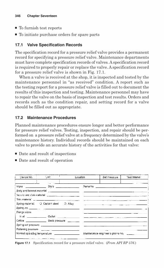
To furnish test reports To initiate purchase orders for spare parts
17.1 Valve Specification Records
The specification record for a pressure relief valve provides a permanentrecord for specifying a pressure relief valve. Maintenance departmentsmust have complete specification records of valves. A specification recordis required to properly repair or replace the valve. A specification recordfor a pressure relief valve is shown in Fig. 17.1.
When a valve is received at the shop, it is inspected and tested by themaintenance personnel in “as received” condition. A report such asthe testing report for a pressure relief valve is filled out to document theresults of this inspection and testing. Maintenance personnel may haveto repair the valve on the basis of inspection and test results. Orders andrecords such as the condition repair, and setting record for a valveshould be filled out as appropriate.
17.2 Maintenance Procedures
Planned maintenance procedures ensure longer and better performancefor pressure relief valves. Testing, inspection, and repair should be per-formed on a pressure relief valve at a frequency determined by the valve’smaintenance history. Individual records should be maintained on eachvalve to provide an accurate history of the activities for that valve:
Date and result of inspections Date and result of operation
346 Chapter Seventeen
Figure 17.1 Specification record for a pressure relief valve. (From API RP 576.)
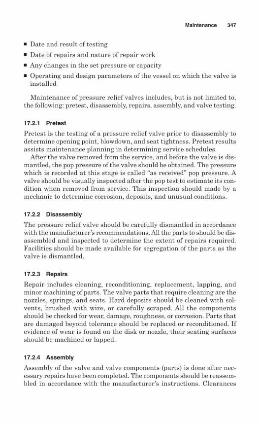
Date and result of testing Date of repairs and nature of repair work Any changes in the set pressure or capacity Operating and design parameters of the vessel on which the valve is
installed
Maintenance of pressure relief valves includes, but is not limited to,the following: pretest, disassembly, repairs, assembly, and valve testing.
17.2.1 Pretest
Pretest is the testing of a pressure relief valve prior to disassembly todetermine opening point, blowdown, and seat tightness. Pretest resultsassists maintenance planning in determining service schedules.
After the valve removed from the service, and before the valve is dis-mantled, the pop pressure of the valve should be obtained. The pressurewhich is recorded at this stage is called “as received” pop pressure. Avalve should be visually inspected after the pop test to estimate its con-dition when removed from service. This inspection should made by amechanic to determine corrosion, deposits, and unusual conditions.
17.2.2 Disassembly
The pressure relief valve should be carefully dismantled in accordancewith the manufacturer’s recommendations. All the parts to should be dis-assembled and inspected to determine the extent of repairs required.Facilities should be made available for segregation of the parts as thevalve is dismantled.
17.2.3 Repairs
Repair includes cleaning, reconditioning, replacement, lapping, andminor machining of parts. The valve parts that require cleaning are thenozzles, springs, and seats. Hard deposits should be cleaned with sol-vents, brushed with wire, or carefully scraped. All the componentsshould be checked for wear, damage, roughness, or corrosion. Parts thatare damaged beyond tolerance should be replaced or reconditioned. Ifevidence of wear is found on the disk or nozzle, their seating surfacesshould be machined or lapped.
17.2.4 Assembly
Assembly of the valve and valve components (parts) is done after nec-essary repairs have been completed. The components should be reassem-bled in accordance with the manufacturer’s instructions. Clearances
Maintenance 347
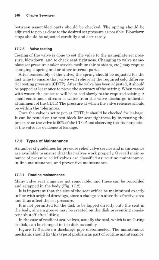
between assembled parts should be checked. The spring should beadjusted to pop as close to the desired set pressure as possible. Blowdownrings should be adjusted carefully and accurately.
17.2.5 Valve testing
Testing of the valve is done to set the valve to the nameplate set pres-sure, blowdown, and to check seat tightness. Changing to valve name-plate set pressure and/or service medium (air to steam, etc.) may requirechanging a spring and or other internal parts.
After reassembly of the valve, the spring should be adjusted for thelast time to ensure that valve will relieve at the required cold differen-tial testing pressure (CDTP). After the valve has been adjusted, it shouldbe popped at least once to prove the accuracy of the setting. When testedwith water, the pressure will be raised slowly to the required setting. Asmall continuous stream of water from the valve discharge indicatesattainment of the CDTP. The pressure at which the valve releases shouldbe within the tolerances.
Once the valve is set to pop at CDTP, it should be checked for leakage.It can be tested on the test block for seat tightness by increasing thepressure on the valve to 90% of the CDTP and observing the discharge sideof the valve for evidence of leakage.
17.3 Types of Maintenance
A number of guidelines for pressure relief valve service and maintenanceare available to ensure that that valves work properly. Overall mainte-nance of pressure relief valves are classified as: routine maintenance,in-line maintenance, and preventive maintenance.
17.3.1 Routine maintenance
Many valve seat rings are not removable, and these can be reprofiledand relapped in the body (Fig. 17.2).
It is important that the size of the seat orifice be maintained exactlyin line with original drawings, since a change can alter the effective areaand thus affect the set pressure.
It is not permitted for the disk to be lapped directly onto the seat inthe body, since a groove may be created on the disk preventing consis-tent shutoff after lifting.
In the case of resilient seal valves, usually the seal, which is an O-ringor disk, can be changed in the disk assembly.
Figure 17.3 shows a discharge pipe disconnected. The maintenancemechanic should fix this type of problem as part of routine maintenance.
348 Chapter Seventeen
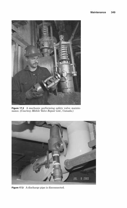
Maintenance 349
Figure 17.3 A discharge pipe is disconnected.
Figure 17.2 A mechanic performing safety valve mainte-nance. (Courtesy Mobile Valve Repair Ltd., Canada.)
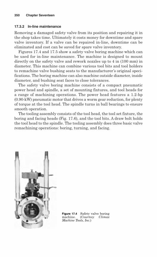
17.3.2 In-line maintenance
Removing a damaged safety valve from its position and repairing it inthe shop takes time. Ultimately it costs money for downtime and sparevalve inventory. If a valve can be repaired in-line, downtime can beeliminated and cost can be saved for spare valve inventory.
Figures 17.4 and 17.5 show a safety valve boring machine which canbe used for in-line maintenance. The machine is designed to mountdirectly on the safety valve and rework nozzles up to 4 in (100 mm) indiameter. This machine can combine various tool bits and tool holdersto remachine valve bushing seats to the manufacturer’s original speci-fications. The boring machine can also machine outside diameter, insidediameter, and bushing seat faces to close tolerances.
The safety valve boring machine consists of a compact pneumaticpower head and spindle, a set of mounting fixtures, and tool heads fora range of machining operations. The power head features a 1.2-hp(0.90-kW) pneumatic motor that drives a worm gear reduction, for plentyof torque at the tool head. The spindle turns in ball bearings to ensuresmooth operation.
The tooling assembly consists of the tool head, the tool set fixture, theboring and facing heads (Fig. 17.6), and the tool bits. A draw bolt holdsthe tool head to the spindle. The tooling assembly does three basic valveremachining operations: boring, turning, and facing.
350 Chapter Seventeen
Figure 17.4 Safety valve boringmachine. (Courtesy ClimaxMachine Tools, Inc.)
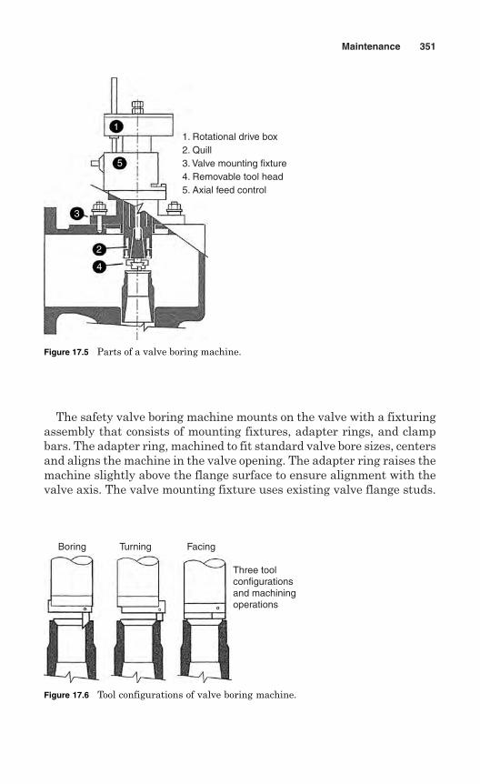
The safety valve boring machine mounts on the valve with a fixturingassembly that consists of mounting fixtures, adapter rings, and clampbars. The adapter ring, machined to fit standard valve bore sizes, centersand aligns the machine in the valve opening. The adapter ring raises themachine slightly above the flange surface to ensure alignment with thevalve axis. The valve mounting fixture uses existing valve flange studs.
Maintenance 351
Boring Turning Facing
Three toolconfigurationsand machiningoperations
Figure 17.6 Tool configurations of valve boring machine.
1
5
3
2
4
1. Rotational drive box2. Quill3. Valve mounting fixture4. Removable tool head5. Axial feed control
Figure 17.5 Parts of a valve boring machine.
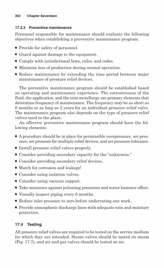
17.3.3 Preventive maintenance
Personnel responsible for maintenance should evaluate the followingobjectives when establishing a preventive maintenance program:
Provide for safety of personnel. Guard against damage to the equipment. Comply with jurisdictional laws, rules, and codes. Minimize loss of production during normal operation. Reduce maintenance by extending the time period between major
maintenance of pressure relief devices.
The preventive maintenance program should be established basedon operating and maintenance experience. The corrosiveness of thefluid, the application, and the trim metallurgy are primary elements thatdetermine frequency of maintenance. The frequency may be as short as6 months or as long as 2 years for an individual pressure relief valve.The maintenance program also depends on the type of pressure reliefvalves used in the plant.
An effective preventive maintenance program should have the fol-lowing elements:
A procedure should be in place for permissible overpressure, set pres-sure, set pressure for multiple relief devices, and set pressure tolerance.
Install pressure relief valves properly. Consider providing secondary capacity for the “unknowns.” Consider providing secondary relief devices. Watch for corrosion and leakage! Consider using isolation valves. Consider using vacuum support. Take measures against pulsating pressures and water hammer effect. Visually inspect piping every 6 months. Reduce inlet pressure to zero before underrating any work. Provide atmospheric discharge lines with adequate rain and moisture
protection.
17.4 Testing
All pressure relief valves are required to be tested on the service mediumfor which they are intended. Steam valves should be tested on steam(Fig. 17.7), and air and gas valves should be tested on air.
352 Chapter Seventeen
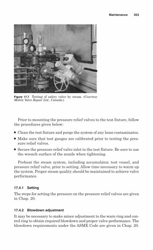
Prior to mounting the pressure relief valves to the test fixture, followthe procedures given below:
Clean the test fixture and purge the system of any loose contaminates. Make sure that test gauges are calibrated prior to testing the pres-
sure relief valves. Secure the pressure relief valve inlet to the test fixture. Be sure to use
the wrench surface of the nozzle when tightening.
Preheat the steam system, including accumulator, test vessel, andpressure relief valve, prior to setting. Allow time necessary to warm upthe system. Proper steam quality should be maintained to achieve valveperformance.
17.4.1 Setting
The steps for setting the pressure on the pressure relief valves are givenin Chap. 20.
17.4.2 Blowdown adjustment
It may be necessary to make minor adjustment to the warn ring and con-trol ring to obtain required blowdown and proper valve performance. Theblowdown requirements under the ASME Code are given in Chap. 20.
Maintenance 353
Figure 17.7 Testing of safety valve by steam. (CourtesyMobile Valve Repair Ltd., Canada.)
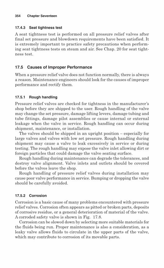
17.4.3 Seat tightness test
A seat tightness test is performed on all pressure relief valves afterfinal set pressure and blowdown requirements have been satisfied. Itis extremely important to practice safety precautions when perform-ing seat tightness tests on steam and air. See Chap. 20 for seat tight-ness test.
17.5 Causes of Improper Performance
When a pressure relief valve does not function normally, there is alwaysa reason. Maintenance engineers should look for the causes of improperperformance and rectify them.
17.5.1 Rough handling
Pressure relief valves are checked for tightness in the manufacturer’sshop before they are shipped to the user. Rough handling of the valvemay change the set pressure, damage lifting levers, damage tubing andtube fittings, damage pilot assemblies or cause internal or externalleakage when the valve in service. Rough handling can occur duringshipment, maintenance, or installation.
The valves should be shipped in an upright position – especially forlarge valves and valves with low set pressure. Rough handling duringshipment may cause a valve to leak excessively in service or duringtesting. The rough handling may expose the valve inlet allowing dirt orforeign particles that could damage the valve seating surface.
Rough handling during maintenance can degrade the tolerances, anddestroy valve alignment. Valve inlets and outlets should be coveredbefore the valves leave the shop.
Rough handling of pressure relief valves during installation maycause poor valve performance in service. Bumping or dropping the valveshould be carefully avoided.
17.5.2 Corrosion
Corrosion is a basic cause of many problems encountered with pressurerelief valves. Corrosion often appears as pitted or broken parts, depositsof corrosive residue, or a general deterioration of material of the valve.A corroded safety valve is shown in Fig. 17.8.
Corrosion can be slowed down by selecting more suitable materials forthe fluids being run. Proper maintenance is also a consideration, as aleaky valve allows fluids to circulate in the upper parts of the valve,which may contribute to corrosion of its movable parts.
354 Chapter Seventeen
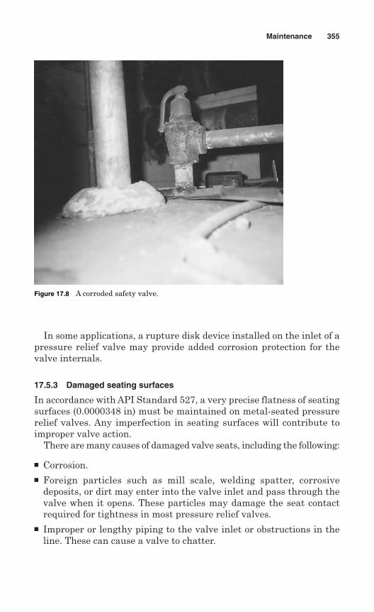
In some applications, a rupture disk device installed on the inlet of apressure relief valve may provide added corrosion protection for thevalve internals.
17.5.3 Damaged seating surfaces
In accordance with API Standard 527, a very precise flatness of seatingsurfaces (0.0000348 in) must be maintained on metal-seated pressurerelief valves. Any imperfection in seating surfaces will contribute toimproper valve action.
There are many causes of damaged valve seats, including the following:
Corrosion. Foreign particles such as mill scale, welding spatter, corrosive
deposits, or dirt may enter into the valve inlet and pass through thevalve when it opens. These particles may damage the seat contactrequired for tightness in most pressure relief valves.
Improper or lengthy piping to the valve inlet or obstructions in theline. These can cause a valve to chatter.
Maintenance 355
Figure 17.8 A corroded safety valve.
Rough handling during maintenance, such as bumping, dropping, jar-ring, or scratching of valve parts.
Leakage past the seating surfaces of a valve after it has been installed.Seat leakage may also result from the operating pressure being tooclose to the set pressure of the valve.
Improper blowdown ring setting can cause chattering in pressurerelief valves.
17.5.4 Failed springs
Spring failure may occur in two forms––weakening of the spring, anda total failure of the spring. Although spring may be weaken and fail dueto the use of improper materials at high temperature service, most ofthe springs fail due to corrosion.
When corrosion is the reason for failure, the following actions may betaken:
A spring material that resists the action of corrosive agent may beused.
The spring may be isolated by a bellows. The spring may be coated with a corrosion-resistance coating that
can withstand the operating temperature and environment.
17.5.5 Improper setting and adjustment
The manufacturer’s recommendations should be followed to eliminateimproper setting and adjustment by indicating how to adjust the pres-sure relief valves for temperature, back pressure, and other factors.Generally, pressure relief valves are set in the maintenance shop onappropriate test equipment.
The following guidelines may be used for proper setting and adjustment:
Vapor-service valves should be tested on air or inert gas. Steam-service valve should be tested on steam, but air may be used if suit-able corrections are applied. Liquid-service valves should be setusing water.
The size of the test stand is important, as insufficient surge volumemight not cause a distinct pop, and may cause an incorrect set pressure.
Consult the manufacturer for proper techniques for setting pilot-operated pressure relief valves for liquid service.
Gauges should be calibrated frequently on a regularly calibrated dead-weight tester.
356 Chapter Seventeen
The valve adjusting rings control either the blowdown (the differencebetween the set pressure and reseating pressure) or valve blowdownand simmer, depending on the design of the valve. The rings shouldbe adjusted to obtain pop on the valve test drum, and then readjustedfor proper blowdown.
The manufacturer should be contacted regarding the proper blow-down ring settings for liquid or vapor service.
17.5.6 Plugging and sticking
In refineries, process solids such as coke or solidified products may plugvarious parts of the pressure relief valve and its connected piping. Inaddition, monomer service may lead to polymer formation and plugging.
The following steps may be taken to avoid plugging and sticking:
All valve parts, especially guiding parts, should be checked for anytype of fouling surfaces.
Lubricate all bearing surfaces, such as the spindle to the disk holder,spring buttons to the spindle, disk to disk holder, and threads.
Valves may malfunction due to sticking of the disk or disk holder inthe guide, which may be caused by corrosion. Sticking of valves mayalso result from matching of valve parts outside the tolerance limits.
Sticking of pressure relief valves may also be caused by poor alignmentof the valve disk.
If corrosion is the cause of sticking, possible solutions are:- The use of a bellows to protect moving parts from the corrosive
substances.- An O-ring seat can seal the guiding surfaces from the lading fluid
until a relief cycle occurs.- The use of a rupture disk on the valve inlet should isolate the valve
internals from the upstream process materials.
17.5.7 Misapplication of materials
Special attention is required in selection of materials for severe corro-sion or unusual pressure or temperature conditions in the process. Theproper materials for the valves may be selected based on the followingguidelines:
Determine the materials to be used, considering the temperature,pressure, corrosion resistance, and atmospheric conditions of service.
Read manufacturers’ catalogs for a wide choice of special materials andaccessories for various chemical and temperature conditions.
Maintenance 357
Note that hydrogen sulfide (H2S) attacks carbon steel springs, andchloride attacks 18Cr-8Ni steel disks.
Care should be taken to record the identity of special materials andthe locations requiring them.
17.5.8 Improper discharge piping test
Blinds should be installed when hydrostatic tests of discharge piping areperformed. The following might result if blinds are not used:
The disk, spring, and body area on the discharge side of the valve maybe fouled.
The bellows of a valve may be damaged by excessive back pressure. The dome area/or pilot assembly may be fouled and damaged by the
backflow of fluid.
17.6 Troubleshooting
Like any other mechanical equipment, pressure relief valves give trou-bles during operation. Maintenance personnel are responsible for diag-nosis of troubles and taking corrective actions to restore valves’ normaloperation. Table 17.1 offers guidelines for troubleshooting.
17.7 Spare Parts
The maintenance department should stock spare parts which may berequired on emergency basis. Commonly supplied spare parts are:
Springs (Fig. 17.9) Disks Disk holders Nozzles Rings Guides Spindles Resilient seals Gaskets Compression screws
358 Chapter Seventeen
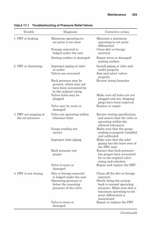
Maintenance 359
TABLE 17.1 Troubleshooting of Pressure Relief Valves
Trouble Diagnosis Corrective action
1. PRV is leaking Minimum operating-to- Maintain a minimumset point is too close operating-to-set point
differential Foreign material is Clean dirt or foreignlodged under the seat material
Seating surface is damaged Repair worn or damagedseating surface
2. PRV is chattering Improper piping at inlet Install piping at inlet andor outlet outlet properly
Valves are oversized Size and select valves properly
Back pressure may be Review sizing formulaspresent, which may nothave been accounted forin the original sizing
Valves holes may be Make sure all holes are notplugged plugged and any shipping
plugs have been removedValve may be worn or Replace or repairdamaged
3. PRV not popping at Valve not operating within Review testing specificationthe set pressure tolerance limit and ensure that the valve is
operating within theallowed tolerances
Gauge reading not Make sure that the gauge correct reading is properly installed
and calibratedImproper inlet piping Make sure that the inlet
piping has the least area ofthe PRV inlet
Back pressure not Ensure that back pressureproper has proper been accounted
for in the original valvesizing and selection
Valve is worn or Repair and replace the PRVdamaged
4. PRV is not closing Dirt or foreign material Clean off the dirt or foreignis lodged under the seat material
Operating pressure is Slowly bring the systembelow the reseating back to normal operating pressure of the valve pressure. Make sure that a
minimum operating-to-set point differential is maintained
Valve is worn or Repair or replace the PRV damaged
(Continued)
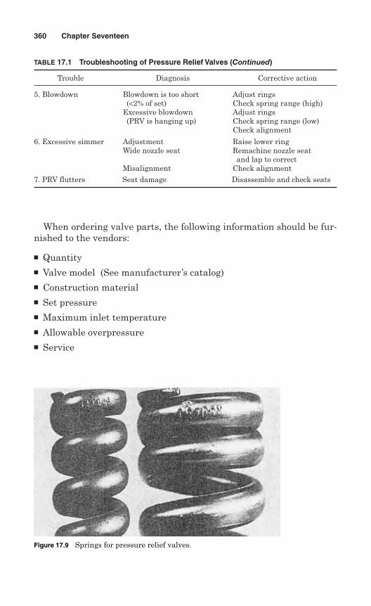
When ordering valve parts, the following information should be fur-nished to the vendors:
Quantity Valve model (See manufacturer’s catalog) Construction material Set pressure Maximum inlet temperature Allowable overpressure Service
360 Chapter Seventeen
TABLE 17.1 Troubleshooting of Pressure Relief Valves (Continued)
Trouble Diagnosis Corrective action
5. Blowdown Blowdown is too short Adjust rings(<2% of set) Check spring range (high)
Excessive blowdown Adjust rings(PRV is hanging up) Check spring range (low)
Check alignment
6. Excessive simmer Adjustment Raise lower ring Wide nozzle seat Remachine nozzle seat
and lap to correctMisalignment Check alignment
7. PRV flutters Seat damage Disassemble and check seats
Figure 17.9 Springs for pressure relief valves.

Required capacity Accessories Code requirements
17.8 Storage
Pressure relief valves and their parts should be properly stored andprotected. Performance of the pressure relief valve may be seriouslyaffected if they are not stored properly. Rough handling may damageflanges or cause misalignment of the valve parts. It is recommended toleave valves in their shipment cases and store them in a dry place undercover until they are to be used.
Maintenance 361

This page intentionally left blank
Chapter
Inspection
A properly designed, constructed, and installed pressure relief device issupposed to ensure safety of personnel and protect equipment duringabnormal circumstances. Inspection of pressure-relieving devices is per-formed to ensure that they provide this protection in case of emergencysituations.
Inspection of pressure relief devices should determine the generalphysical and operating conditions of these devices, and ensure theirperformance. In order to make this determination, thorough inspectionin the shop and visual inspection on stream are conducted.
The inspection should include necessary factors which could affect thepressure relief valve performance. The followings are considered impor-tant factors:
Temperature variation, both system and ambient Vibration Residue on valve internal parts Valve body mechanical stresses Line turbulence Sizing and configuration of discharge piping Sizing and configuration of inlet piping Bore diameter
Pressure relief devices are inspected by an Authorized Inspector (AI)who is qualified by the jurisdiction. Depending on jurisdictional laws andrules, pressure relief devices are inspected regularly by an AI. Inspectionis a complex technique, and the AI must have knowledge and experience
363
18
Copyright © 2006 by The McGraw-Hill Companies, Inc. Click here for terms of use.
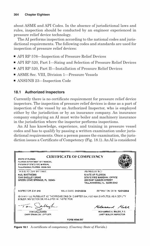
about ASME and API Codes. In the absence of jurisdictional laws andrules, inspection should be conducted by an engineer experienced inpressure relief device technology.
The AI performs inspection according to the national codes and juris-dictional requirements. The following codes and standards are used forinspection of pressure relief devices:
API RP 576—Inspection of Pressure Relief Devices API RP 520, Part I—Sizing and Selection of Pressure Relief Devices API RP 520, Part II—Installation of Pressure Relief Devices ASME Sec. VIII, Division 1—Pressure Vessels ANSI/NB 23—Inspection Code
18.1 Authorized Inspectors
Currently there is no certificate requirement for pressure relief deviceinspectors. The inspection of pressure relief devices is done as a part ofinspection of the vessel by an Authorized Inspector, who is employedeither by the jurisdiction or by an insurance company. An insurancecompany employing an AI must write boiler and machinery insurancein the jurisdiction where the inspector performs inspections.
An AI has knowledge, experience, and training in pressure vesselcodes and has to qualify by passing a written examination under juris-dictional requirements. Once a person passes the examination, the juris-diction issues a Certificate of Competency (Fig. 18.1). An AI is considered
364 Chapter Eighteen
Figure 18.1 A certificate of competency. (Courtesy State of Florida.)
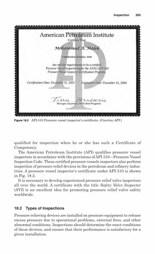
qualified for inspection when he or she has such a Certificate ofCompetency.
The American Petroleum Institute (API) qualifies pressure vesselinspectors in accordance with the provisions of API 510—Pressure VesselInspection Code. These certified pressure vessels inspectors also performinspection of pressure relief devices in the petroleum and refinery indus-tries. A pressure vessel inspector’s certificate under API-510 is shownin Fig. 18.2.
It is necessary to develop experienced pressure relief valve inspectorsall over the world. A certificate with the title Safety Valve Inspector(SVI) is an excellent idea for promoting pressure relief valve safetyworldwide.
18.2 Types of Inspections
Pressure relieving devices are installed on pressure equipment to releaseexcess pressure due to operational problems, external fires, and otherabnormal conditions. Inspections should determine the exact conditionsof these devices, and ensure that their performance is satisfactory for agiven installation.
Inspection 365
Figure 18.2 API-510 Pressure vessel inspector’s certificate. (Courtesy API.)
To ensure that pressure relief devices will function in case of abnor-mal circumstances, the following types of inspections are performed:
Inspection of new installations Routine inspection Shop inspection Visual on-stream inspection In-service testing Unscheduled inspection
18.2.1 Inspection of new installations
All new pressure relief valves should be inspected and tested before and afterthey are installed on equipment. Inspect the pressure relief valves visuallyand verify cold differential test pressure (CDTP) pressure. This inspectionshould determine any damage or changes in factory adjustment due to ship-ping. Be sure to confirm the set pressure, and keep appropriate records.
Pressure and/or vacuum vent valves on atmospheric storage tanksshould be inspected after installation but before the tank is hydrostat-ically tested or put into service.
18.2.2 Routine inspection
Routine inspection is carried out when the plant is shutdown and main-tenance manpower is available. Generally, the interval between routineinspections is determined by operating experience in the variousprocesses involved. The interval of a pressure relief device in a corro-sive or fouling service would be shorter than the interval required forthe same device for non-fouling, non-corrosive service.
All relief valves not equipped with block valves should be inspectedat this time. If an inspection carried out during this shutdown, theinspection should be scheduled for the next shutdown. Even the pres-sure relief valves with block valves may be inspected to minimize processinterruptions, and avoiding inspection in operation.
18.2.3 Shop inspection
Periodically, pressure relief devices are removed, disassembled, andinspected in the shop. This inspection is referred to as shop inspection.
Each pressure relief valve in the shop should carry an identificationtag or other means to show its company equipment number. Thisnumber allows ready identification of the equipment that the valveshould be installed on. An operating history of each tag number since
366 Chapter Eighteen
its last shop inspection should be obtained and should include the fol-lowing information:
Information on upsets and their effect on the valve The extent of any leakage while in service Any other evidence of malfunctioning
As soon as a pressure relief valve is received in the shop, a visualinspection should be made. Any deposits, corrosion products or obstruc-tions in the valve should be recorded and removed.
Qualified maintenance personnel do a thorough overhaul in the shopand make the pressure relief devices ready for service. Prior to theinstallation of a pressure relief valve, the inlet and outlet piping shouldbe inspected for presence of internal deposits. If fouling is observed, thepiping should be cleaned.
18.2.4 Visual on-stream inspection
A visual on-stream inspection is similar to a survey and is considered acontrol measure rather than normal inspection. A full visual on-streaminspection should ensure the following:
The relief valve does not leak. Detection and correction of leakageeliminates product loss, and prevents fouling.
Bellows vents are open and clear. Upstream and downstream block valves are sealed or chained or
locked in proper position. Valve body drains and vent stack drains are open.
18.2.5 In-service testing
An electronic valve tester (EVT) is a digital computerized and hydraulic-assisted device used to test and set pressure relief valves while in serv-ice. The EVT is portable and may be used under normal operatingconditions without overpressurizing the system. The set point of spring-loaded valves may be tested and certified while in service. An electronicvalve tester is shown in Fig. 18.3.
Pressure relief valves which fail the EVT test are required to be removedfor repair. Total downtime and maintenance costs are reduced substantiallybecause of the time saved for valve removal and installation. Since the EVTis calculated from simmer point, potential damage to valve seats fromfull-flow or low-capacity testing is minimized. Electronic valve testing pro-duces computerized certifications for valve records.
Inspection 367
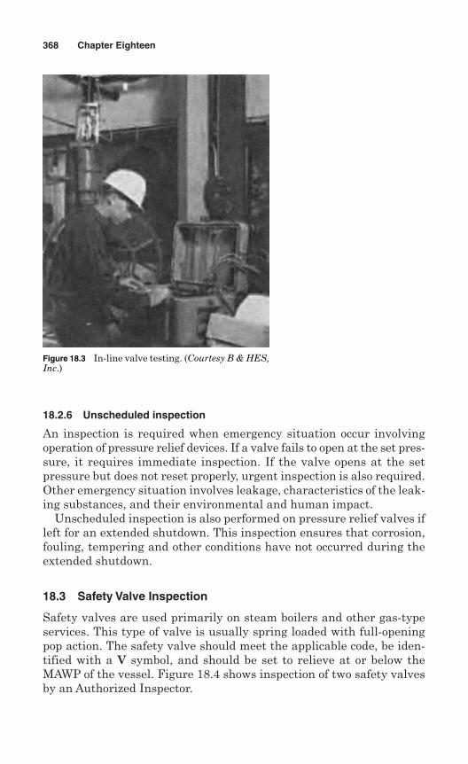
18.2.6 Unscheduled inspection
An inspection is required when emergency situation occur involvingoperation of pressure relief devices. If a valve fails to open at the set pres-sure, it requires immediate inspection. If the valve opens at the setpressure but does not reset properly, urgent inspection is also required.Other emergency situation involves leakage, characteristics of the leak-ing substances, and their environmental and human impact.
Unscheduled inspection is also performed on pressure relief valves ifleft for an extended shutdown. This inspection ensures that corrosion,fouling, tempering and other conditions have not occurred during theextended shutdown.
18.3 Safety Valve Inspection
Safety valves are used primarily on steam boilers and other gas-typeservices. This type of valve is usually spring loaded with full-openingpop action. The safety valve should meet the applicable code, be iden-tified with a V symbol, and should be set to relieve at or below theMAWP of the vessel. Figure 18.4 shows inspection of two safety valvesby an Authorized Inspector.
368 Chapter Eighteen
Figure 18.3 In-line valve testing. (Courtesy B & HES,Inc.)
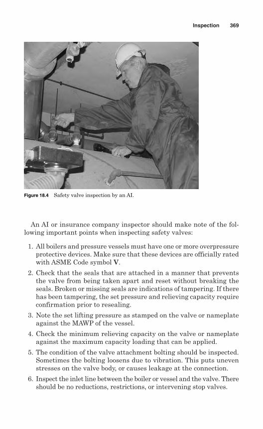
An AI or insurance company inspector should make note of the fol-lowing important points when inspecting safety valves:
1. All boilers and pressure vessels must have one or more overpressureprotective devices. Make sure that these devices are officially ratedwith ASME Code symbol V.
2. Check that the seals that are attached in a manner that preventsthe valve from being taken apart and reset without breaking theseals. Broken or missing seals are indications of tampering. If therehas been tampering, the set pressure and relieving capacity requireconfirmation prior to resealing.
3. Note the set lifting pressure as stamped on the valve or nameplateagainst the MAWP of the vessel.
4. Check the minimum relieving capacity on the valve or nameplateagainst the maximum capacity loading that can be applied.
5. The condition of the valve attachment bolting should be inspected.Sometimes the bolting loosens due to vibration. This puts unevenstresses on the valve body, or causes leakage at the connection.
6. Inspect the inlet line between the boiler or vessel and the valve. Thereshould be no reductions, restrictions, or intervening stop valves.
Inspection 369
Figure 18.4 Safety valve inspection by an AI.
7. Look at the valve proper, and check for cracks in the body, brokensprings, and broken or defective levers. Make sure that there is noaccumulation of rust, soot, scale, or other foreign particles in thecasing or body spring area.
8. If no discharge piping is attached, look inside the discharge open-ing for evidence of leakage. The leakage shows up in the form ofwhite-like mineral deposits, or heavy corrosive deposits. This depositcan interfere with normal operation of the valve.
9. If discharge piping is attached, make sure that it is independentlysupported from the valve body so that the piping loads and stressesare not transmitted to the valve body. Safety valve bodies are notdesigned to carry this loading.
10. Make sure that the discharge piping is carrying full size to a safepoint of discharge with no restrictions or intervening stop valves. Acommon mistake is to reduce the cross-sectional area of a commonline where two or more discharge lines enter a common line.
11. It is permitted by the Code to header discharge lines together,provided the cross sectional areas of the common lines equalsthe sum (cross sectional areas) of all discharge lines entering thecommon.
12. Safety valves must be installed in an upright position with the spin-dle vertical to assure proper operation.
13. If the discharge line is fitted with a drip pan, make sure that thedrip pan and the drip pan drain line are free of scale and other for-eign deposits.
14. Drip pan drains and valve casing drains can be piped together.Ensure that they are piped to a safe point of discharge, and free ofobstructions.
15. A safe point of discharge from the safety valve is an area where thedischarge does not exit directly on personnel or property that maybe damaged by the discharge.
16. Drainage holes at the low point of the discharge piping are requiredto assure that moisture does not accumulate in the piping and thetop of the valve seat. Check the drain holes and make sure thatthey are open.
17. Hazardous or lethal chemicals or gases should be piped to a dump tankwhich provides sufficient capacity to contain accidental discharge.
18. Nonlethal gases which act as oxygen displacers should be piped toan outdoor area. Make sure that the discharge point is clear of anyoutside air inlets to any building. It should be at least 20 ft from anywindow, entrance, or air inlet.
370 Chapter Eighteen
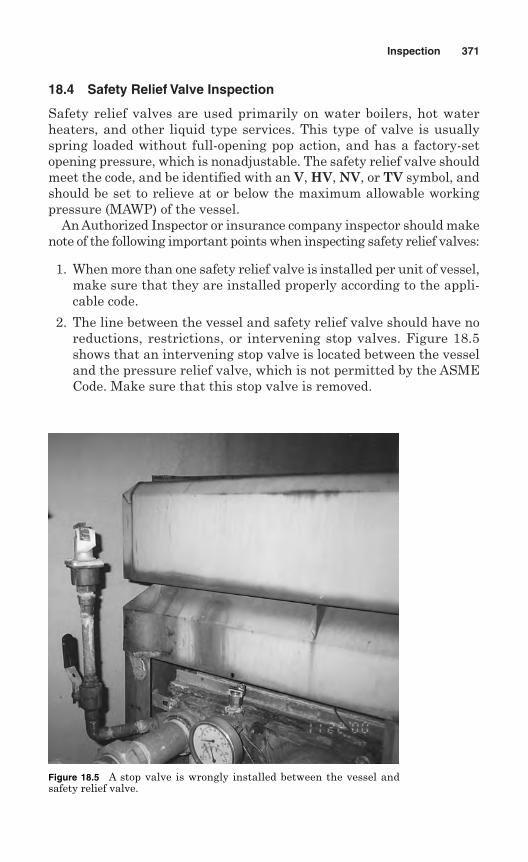
18.4 Safety Relief Valve Inspection
Safety relief valves are used primarily on water boilers, hot waterheaters, and other liquid type services. This type of valve is usuallyspring loaded without full-opening pop action, and has a factory-setopening pressure, which is nonadjustable. The safety relief valve shouldmeet the code, and be identified with an V, HV, NV, or TV symbol, andshould be set to relieve at or below the maximum allowable workingpressure (MAWP) of the vessel.
An Authorized Inspector or insurance company inspector should makenote of the following important points when inspecting safety relief valves:
1. When more than one safety relief valve is installed per unit of vessel,make sure that they are installed properly according to the appli-cable code.
2. The line between the vessel and safety relief valve should have noreductions, restrictions, or intervening stop valves. Figure 18.5shows that an intervening stop valve is located between the vesseland the pressure relief valve, which is not permitted by the ASMECode. Make sure that this stop valve is removed.
Inspection 371
Figure 18.5 A stop valve is wrongly installed between the vessel andsafety relief valve.
3. The safety relief valve should be installed top or side at the highestpossible part of the vessel proper. In no case may this valve beinstalled below the lowest permissible water level of the vessel.
4. The safety relief valve should be connected directly to a tapped orflanged opening in the vessel.
5. The discharge pipe should be as short as possible, and arranged toavoid undue stress loadings on the valve.
6. If the valve discharges liquids, the discharge piping should be pipedto the floor or drain areas to minimize scalding of personnel.
7. The piping discharge point should be no closer than one pipe diam-eter above the floor, or any obstruction. It should be no higher abovethe floor than three pipe diameters.
8. A common error is to set the discharge pipe directly on a drain plate.The webbing in the plate reduces the safety relief valve capacity.Check the discharge piping exit point to ensure that it is notobstructed in any manner.
9. Inspect the body casing and spring area for cracked or broken parts.Look for leakage in the area in the form of white-like mineraldeposits or corrosion that might obstruct the movement of spring oroperation of the valve.
10. Examine the discharge piping exit point for evidence of relief valveleakage. If any leakage is found, it should be corrected or the valvereplaced.
11. A safety relief valve should have a try lever and should be sealed.Safety relief valve inlet size should not be smaller than 3/4 in, norgreater than 4 in.
12. A safety relief valve is required to be installed with the valve spin-dle in the vertical position to assure proper operation.
18.5 Rupture Disk Inspection
All rupture disk devices should be thoroughly inspected before instal-lation. The manufacturer’s instructions should be followed for specificrupture disks. The seating surfaces of the rupture disk holder shouldbe clean, smooth, and undamaged.
Rupture disks should be checked for physical damage to the seatingsurfaces or the prebulged area. Damaged or dented disks should not beused. The disk should not be reinstalled once it has been removed fromits holder, even though it has not been ruptured. The safety head orbolted construction should be checked for proper torque as recommendedby the manufacturer.
372 Chapter Eighteen
The knife blades on reverse buckling disks should be checked forphysical damage and sharpness. Nicked or dull blades should be refur-bished or replaced.
Inlet and discharge piping for rupture disks should meet the same cri-teria as established for safety relief valves and safety valves.
Rupture disks should be replaced on a regular schedule based on theirapplication, manufacturer’s recommendations, and user’s past experi-ence. If the risk of a rupture disk opening prematurely is low, and inletand outlet fouling is monitored, the disk may be left in place indefinitely.
18.6 Records and Reports
An Authorized Inspector or insurance company inspector usually com-pletes a report after inspection of a vessel. The report contains a lot ofinformation about the safety relief devices.
Figure 18.6 is an example of a boiler reinspection report submitted byan insurance inspector to the State of Florida. In his report, the inspec-tor has specified that the safety valve’s capacity is 450,000 Btu/hrwhereas the boiler requires 1,093,000 Btu/hr relieving capacity. Theinspector has written this insufficient capacity as a violation of Par.PG-70 of ASME Code Sec. I. The inspector has asked the owner toreplace the safety valve with an ASME-approved valve capable of reliev-ing the total heat output of the boiler.
Figure 18.7 shows a form for historical records indicating dates andresults of inspections and tests necessary for the follow-up phase of thepressure-relieving inspection program. The record also indicates peri-odic reviews to determine if the planned inspection intervals for a deviceare being realized. It is important that the records offer a practical basisfor establishing and maintaining safe and economical inspection inter-vals for the device.
Inspection 373
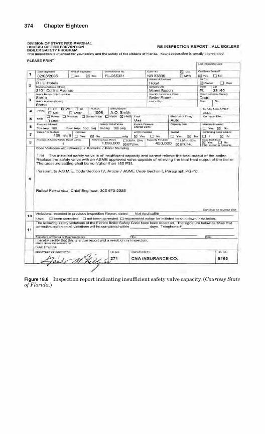
374 Chapter Eighteen
Figure 18.6 Inspection report indicating insufficient safety valve capacity. (Courtesy Stateof Florida.)
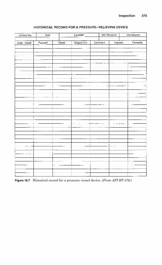
Inspection 375
Figure 18.7 Historical record for a pressure vessel device. (From API RP 576.)

This page intentionally left blank
Chapter
Repairs
Repair work is necessary to restore a pressure relief device to a safe andsatisfactory condition. Pressure relief devices should be carefully repairedin accordance with the manufacturers’ manuals and recommendations.The repair method should conform to a national standard, and the workshould be done by qualified repairers. If the repair is not done properly,the pressure relief device may give major technical problems in service.
Pressure relief valves may be repaired on the system or may berepaired in a valve repair shop. Repairs on pressure relief valves shouldbe performed by a repairing firm or person, who has necessary tools andsurface finish data for the valves. As a part of repair process, all dimen-sions of the nozzle, disk, disk holder, ring, guide, and spindle should bechecked and restored to their original standard.
If all the dimensions and surface finish data is not available for repair,the parts should be replaced by the parts from the original valve man-ufacturer. The valve may not function properly when parts supplied bya company other than original valve manufacturer is used. All pats tobe used should be free from scoring damage to critical guiding surfaces.
On completion of all repairs, pressure relief valve should be tested andsealed to ensure that no unauthorized adjustments are made. Generally,testing is done in a valve repair shop, where necessary testing facilitiesare available and the shop has adequate test capacities. If all the valveoperating characteristics cannot be tested in the shop, they should beverified when the boiler is on line.
19.1 Repairers
A repair organization must have experience in handling, maintenance,and repair of all types of pressure relief devices. Most jurisdictions havequalification requirements for a repair organization in the laws and rules.
377
19
Copyright © 2006 by The McGraw-Hill Companies, Inc. Click here for terms of use.
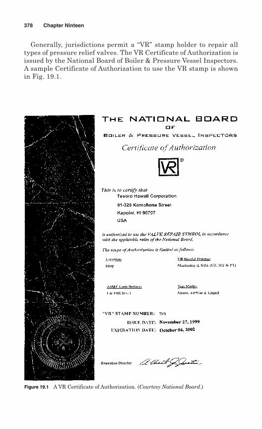
Generally, jurisdictions permit a “VR” stamp holder to repair alltypes of pressure relief valves. The VR Certificate of Authorization isissued by the National Board of Boiler & Pressure Vessel Inspectors.A sample Certificate of Authorization to use the VR stamp is shownin Fig. 19.1.
378 Chapter Ninteen
Figure 19.1 A VR Certificate of Authorization. (Courtesy National Board.)
Each repair organization should have a fully documented quality con-trol system. As a minimum, the following requirements and sets of doc-umentation should be included in the quality control system:
Title page Revision log Contents page Statement of authority and responsibility Organization chart Scope of work Drawings and specification controls Material and part control Repair and inspection program Welding, nondestructive examination, and heat treatment proce-
dures Valve testing, setting, leak testing, and sealing General example of the valve repair nameplate Procedures for calibrating measurement and test gauges Controlled copies of the quality system manuals Sample forms Repair personnel training or qualifications
Each repair organization should also have a fully documented train-ing program that will ensure repair personnel are qualified within thescope of the repair work.
19.2 Repair of Pressure Relief Valves
The repair organization should establish procedures for repairing spring-loaded pressure relief valves. The procedures should cover step-by-steprepair methods to ensure proper repairs.
Generally, repair of pressure relief valves is done in a shop, where allthe machines, equipment, and tools for repair are readily available. Avalve repair shop is shown in Fig. 19.2.
19.2.1 Visual inspection as received
When pressure relief valves are received in the shop, each valve shouldbe visually inspected to detect problems. Generally, this inspection ismade by repair mechanic as a routine procedure. An authorized
Repairs 379
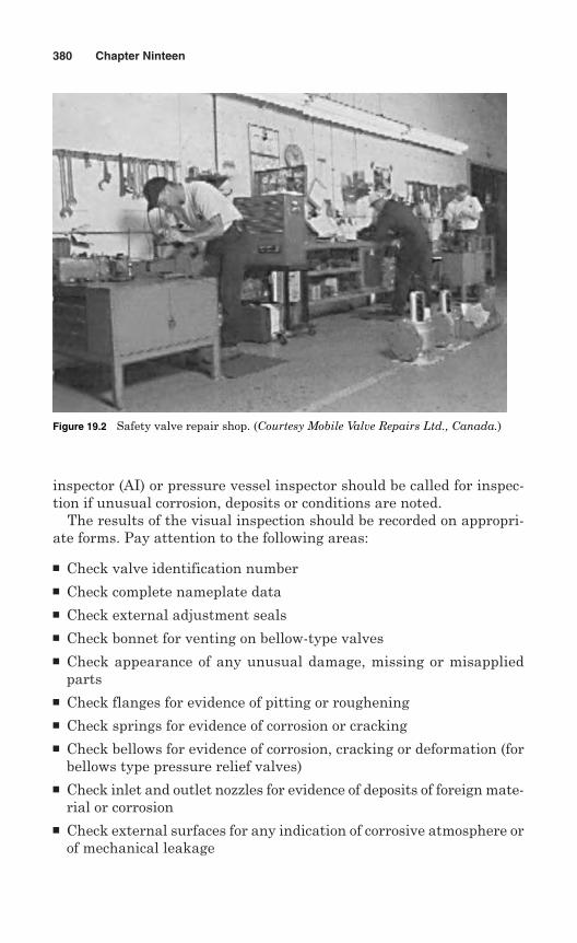
inspector (AI) or pressure vessel inspector should be called for inspec-tion if unusual corrosion, deposits or conditions are noted.
The results of the visual inspection should be recorded on appropri-ate forms. Pay attention to the following areas:
Check valve identification number Check complete nameplate data Check external adjustment seals Check bonnet for venting on bellow-type valves Check appearance of any unusual damage, missing or misapplied
parts Check flanges for evidence of pitting or roughening Check springs for evidence of corrosion or cracking Check bellows for evidence of corrosion, cracking or deformation (for
bellows type pressure relief valves) Check inlet and outlet nozzles for evidence of deposits of foreign mate-
rial or corrosion Check external surfaces for any indication of corrosive atmosphere or
of mechanical leakage
380 Chapter Ninteen
Figure 19.2 Safety valve repair shop. (Courtesy Mobile Valve Repairs Ltd., Canada.)
Check compression screws for sign of wear, pitting and galling Check body wall thickness Check pilots and associated parts (for pilot operated relief valves)
19.2.2 Preliminary test as received
A preliminary performance test is conducted prior to actual repair of thevalve to identify any problems the valve faced in service. Generally, thepressure relief valve is mounted on the test block, and the inlet pres-sure is slowly increased. The pressure at which the valve relieves isrecorded as the “as received” pop pressure or set pressure. The prelim-inary test should record:
Set pressure or cold differential test pressure (CDTP) as per the man-ufacturer’s recommendations and the ASME Code.
The test pressure should not exceed 116% of the set pressure. Conduct at least three tests to obtain consistent results. If results do not correlate with field performance, then make neces-
sary correction to obtain fluid and temperature conditions. Record preliminary test results and test bench identification data.
19.2.3 Disassembly
Pressure relief valves should be dismantled in accordance with the man-ufacturer’s drawings, manuals, and instructions. At each stage of dis-assembly, the various components should be visually inspected forevidence of wear and corrosion. The valve stem, guide, disk, and nozzleshould be visually inspected very carefully.
Follow the following steps for disassembly of pressure relief valves:
Secure the valve inlet wrenching surface in a soft jaw vise, vertically. Remove the seal wire from the warn ring and control ring screw. Remove cap, lever, and release nut assembly. Loosen jam nut on adjusting screw. Record measurement and remove adjusting screw. Remove bonnet or yoke. Remove spring and washers, and put identification tags. Remove spindle and disk assembly. Remove ring pins. Record measurement and remove adjusting rings, nozzle, and guide.
Repairs 381
19.2.4 Cleaning parts
Each part should be cleaned after disassembly of a safety relief valve.Parts may be cleaned with solvents, emery paper, wire brush, sand-blasting, or carefully scraped. The valve parts should be properly markedand segregated so that they are not mixed with parts of other valves.
Proper parts cleaning and condition is a vital part in pressure reliefvalve performance and valve life. Parts which show signs of wear, pit-ting, corrosion or any other damage should be replaced.
Follow the procedures below to clean all parts of pressure relief valves:
Wire all small parts together and clean by means of an abrasive. Do not clean using a chemical solution. Protect seating surfaces, guiding surfaces, and threads prior to
cleaning. Protect valve nameplate when sandblasting body. Avoid sandblasting stems, nozzles, disks, and guides whenever possible. Never use steel shot to clean any parts.
19.2.5 Inspection
After cleaning, all the components should be inspected for wear, corro-sion, and other deterioration. Each part should be checked for dimen-sions with reference to the original valve manufacturer’s drawings andspecifications.
Perform the following inspection on pressure relief valve components:
Check spring for damage such as erosion, corrosion, cracking, break-age or compression below free height.
Check nozzle for cracks using a suitable nondestructive examination(NDE) method. Look for any unusual wear.
Check disk assembly for cracks using a suitable NDE method. Lookfor any unusual wear.
Check spindle for trueness, bearing areas, and threaded condition. Check guide for wear and galling. Check adjusting rings for worn threads and wear. Check ring pins for bent or broken pin and thread condition. Check bellows, if applicable, for pin holes and corrosion. Check flange gasket facings for wear and cuts. Damaged springs, bellows and soft goods should be rejected. Parts that are worn beyond tolerance or damaged should be rejected.
382 Chapter Ninteen
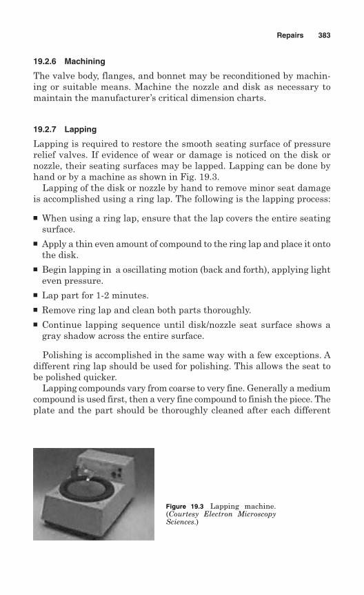
19.2.6 Machining
The valve body, flanges, and bonnet may be reconditioned by machin-ing or suitable means. Machine the nozzle and disk as necessary tomaintain the manufacturer’s critical dimension charts.
19.2.7 Lapping
Lapping is required to restore the smooth seating surface of pressurerelief valves. If evidence of wear or damage is noticed on the disk ornozzle, their seating surfaces may be lapped. Lapping can be done byhand or by a machine as shown in Fig. 19.3.
Lapping of the disk or nozzle by hand to remove minor seat damageis accomplished using a ring lap. The following is the lapping process:
When using a ring lap, ensure that the lap covers the entire seatingsurface.
Apply a thin even amount of compound to the ring lap and place it ontothe disk.
Begin lapping in a oscillating motion (back and forth), applying lighteven pressure.
Lap part for 1-2 minutes. Remove ring lap and clean both parts thoroughly. Continue lapping sequence until disk/nozzle seat surface shows a
gray shadow across the entire surface.
Polishing is accomplished in the same way with a few exceptions. Adifferent ring lap should be used for polishing. This allows the seat tobe polished quicker.
Lapping compounds vary from coarse to very fine. Generally a mediumcompound is used first, then a very fine compound to finish the piece. Theplate and the part should be thoroughly cleaned after each different
Repairs 383
Figure 19.3 Lapping machine.(Courtesy Electron MicroscopySciences.)
compound is used. Coarse compounds should be used for removing deepscratches and must always followed by finer grades. The following lap-ping compounds are recommended:
320 grit for removing small cuts 600 grit for removing scratches 1000 grit for finishing work 1200 grit for polishing
19.2.8 Adjusting rings
Install the lower ring and guide ring to the same position they werewhen removed, or to the manufacturer’s specifications.
19.2.9 Bearing points
Grind all bearing areas with grinding compound to make sure they areround and true.
19.2.10 Assembly
After all the parts have been inspected, reconditioned or replaced, thevalve should be assembled in accordance with the manufacturer’s draw-ings and instructions. In fact assembly is the opposite process of disas-sembly. Each part should be clean, free from burrs and not damagedprior to assembly. Attention should be paid to the seats on the nozzle anddisk. Seats must be free from nicks and scratches.
The following operation is included in assembly of the pressure reliefvalve:
Secure the valve nozzle wrenching surface in a soft jaw vise with thenozzle seat vertical
Check clearance between assembled parts Assemble all the parts according to the instructions Do not oil and seating surfaces Adjust spring to pop as close to the desired set pressure as possible Set blowdown carefully and accurately
19.2.11 Testing
All valves should be tested on the service medium for which they areintended. The following steps should be taken prior to mounting thevalve to the text fixture:
384 Chapter Ninteen
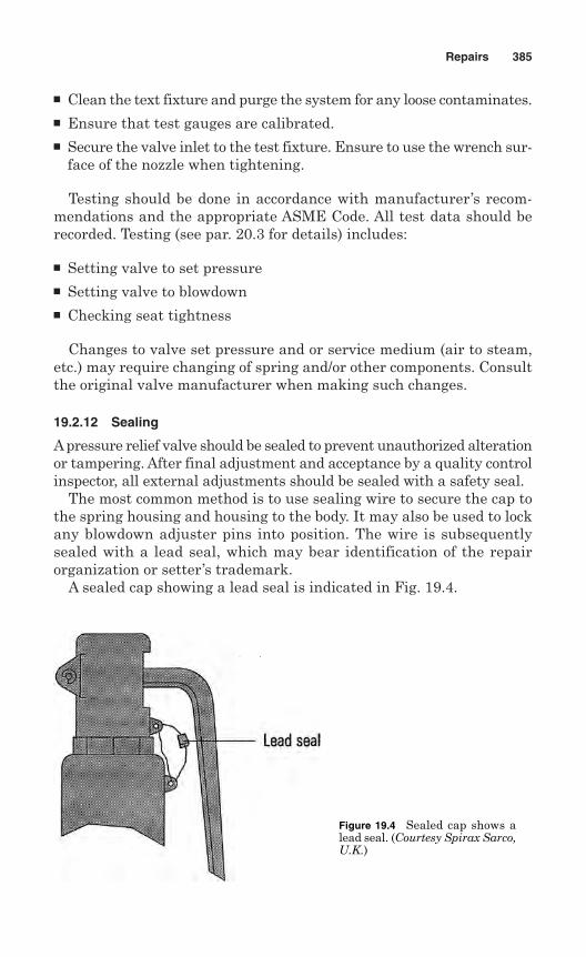
Clean the text fixture and purge the system for any loose contaminates. Ensure that test gauges are calibrated. Secure the valve inlet to the test fixture. Ensure to use the wrench sur-
face of the nozzle when tightening.
Testing should be done in accordance with manufacturer’s recom-mendations and the appropriate ASME Code. All test data should berecorded. Testing (see par. 20.3 for details) includes:
Setting valve to set pressure Setting valve to blowdown Checking seat tightness
Changes to valve set pressure and or service medium (air to steam,etc.) may require changing of spring and/or other components. Consultthe original valve manufacturer when making such changes.
19.2.12 Sealing
Apressure relief valve should be sealed to prevent unauthorized alterationor tampering. After final adjustment and acceptance by a quality controlinspector, all external adjustments should be sealed with a safety seal.
The most common method is to use sealing wire to secure the cap tothe spring housing and housing to the body. It may also be used to lockany blowdown adjuster pins into position. The wire is subsequentlysealed with a lead seal, which may bear identification of the repairorganization or setter’s trademark.
A sealed cap showing a lead seal is indicated in Fig. 19.4.
Repairs 385
Figure 19.4 Sealed cap shows alead seal. (Courtesy Spirax Sarco,U.K.)
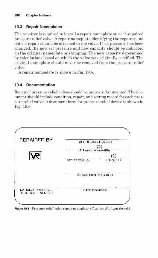
19.3 Repair Nameplates
The repairer is required to install a repair nameplate on each repairedpressure relief valve. A repair nameplate identifying the repairer anddate of repair should be attached to the valve. If set pressure has beenchanged, the new set pressure and new capacity should be indicatedon the original nameplate or stamping. The new capacity determinedby calculations based on which the valve was originally certified. Theoriginal nameplate should never be removed from the pressure reliefvalve.
A repair nameplate is shown in Fig. 19.5.
19.4 Documentation
Repair of pressure relief valves should be properly documented. The doc-ument should include condition, repair, and setting record for each pres-sure relief valve. A document form for pressure relief device is shown inFig. 19.6.
386 Chapter Ninteen
Figure 19.5 Pressure relief valve repair nameplate. (Courtesy National Board.)
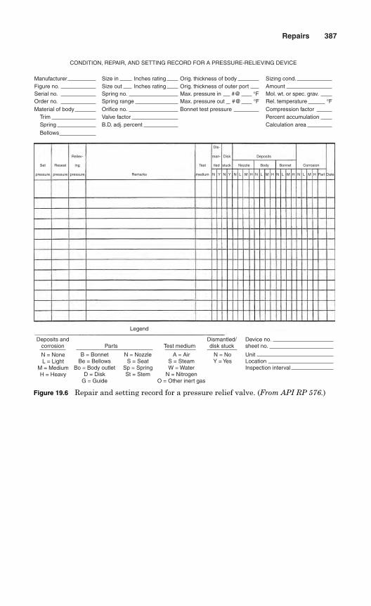
Repairs 387
Set
pressure
Reseat
pressure
ing
Reliev-
pressure Remarks
man- Disk Deposits
Dls-
N Y YN N L M H L M H L M H L M H Part DateN N N
Test tled stuck Nozzle Body Bonnet Corrosion
medium
Deposits andcorrosion
Dismantled/disk stuck
Device no.sheet no.Test mediumParts
N = NoneL = Light
M = MediumH = Heavy
B = BonnetBe = Bellows
Bo = Body outletD = Disk
G = Guide
N = NozzleS = Seat
Sp = SpringSt = Stem
A = AirS = SteamW = Water
N = NitrogenO = Other inert gas
N = NoY = Yes
UnitLocationInspection interval
Legend
CONDITION, REPAIR, AND SETTING RECORD FOR A PRESSURE-RELIEVING DEVICE
ManufacturerFigure no.Serial no.Order no. Material of body
TrimSpring
Bellows
Size inSize out
Inches ratingInches rating
Spring no.Spring range Orifice no.Valve factorB.D. adj. percent
Sizing cond.AmountMol. wt. or spec. grav.Rel. temperature °FCompression factorPercent accumulationCalculation area
Orig. thickness of bodyOrig. thickness of outer portMax. pressure in #@ °FMax. pressure out °F#@Bonnet test pressure
Figure 19.6 Repair and setting record for a pressure relief valve. (From API RP 576.)

This page intentionally left blank
Chapter
Shop Testing
A pressure relief valve is tested in a shop to determine its performance.It is important to determine the set pressure and tightness of the valvebefore putting it into operation. The testing is usually performed on atest stand with facilities for applying pressure to a valve and indicat-ing pressure applied. Most test stands have facilities for testing witheither air or water, to simulate the media handled by pressure reliefvalves. Bottled nitrogen is used for high-pressure valves.
It is not possible to make accurate adjustments of pressure reliefvalves without some way of measuring their performance. The shoptest indicates performance as closely as possible but does not exactlyduplicate field conditions. In a shop test, the amount of liquid or gas apressure relief valve can handle is limited, and it is not practical tomeasure relieving capacity or blowdown. A test stand with insufficientsurge volume may fail, causing a distinct pop, which may result in aninaccurate set pressure. If used properly, a test stand can provide agood indication of the pressure at which the valve will open and itstightness.
The set pressure and tightness are tested according to the applicablecodes. The following national codes are applied to test the performanceof pressure relief valves:
ASME Code Sec. 1—Power Boilers ASME Code Sec. IV—Heating Boilers ASME Code Sec. VIII, Division 1—Pressure Vessels ASME PTC 25—Power Test Code for Pressure Relief Devices API 510—Pressure Vessel Inspection Code API Std 527—Seat Tightness of Pressure Relief Valves
389
20
Copyright © 2006 by The McGraw-Hill Companies, Inc. Click here for terms of use.
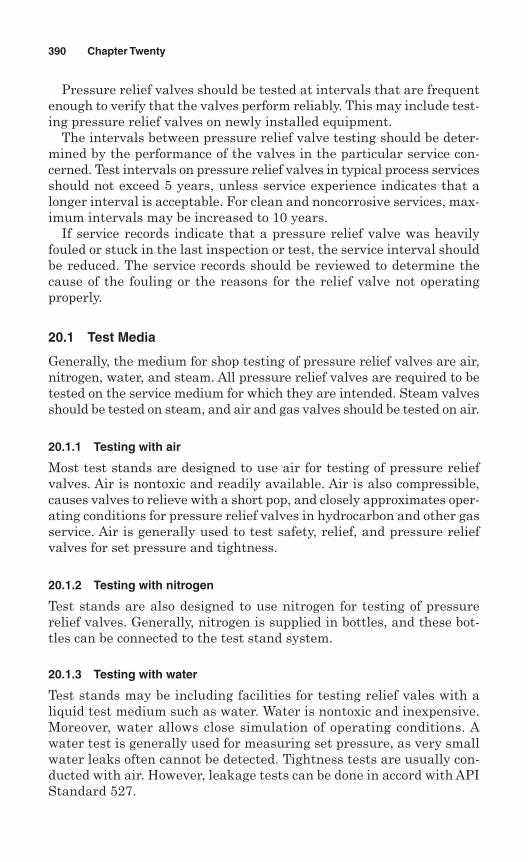
Pressure relief valves should be tested at intervals that are frequentenough to verify that the valves perform reliably. This may include test-ing pressure relief valves on newly installed equipment.
The intervals between pressure relief valve testing should be deter-mined by the performance of the valves in the particular service con-cerned. Test intervals on pressure relief valves in typical process servicesshould not exceed 5 years, unless service experience indicates that alonger interval is acceptable. For clean and noncorrosive services, max-imum intervals may be increased to 10 years.
If service records indicate that a pressure relief valve was heavilyfouled or stuck in the last inspection or test, the service interval shouldbe reduced. The service records should be reviewed to determine thecause of the fouling or the reasons for the relief valve not operatingproperly.
20.1 Test Media
Generally, the medium for shop testing of pressure relief valves are air,nitrogen, water, and steam. All pressure relief valves are required to betested on the service medium for which they are intended. Steam valvesshould be tested on steam, and air and gas valves should be tested on air.
20.1.1 Testing with air
Most test stands are designed to use air for testing of pressure reliefvalves. Air is nontoxic and readily available. Air is also compressible,causes valves to relieve with a short pop, and closely approximates oper-ating conditions for pressure relief valves in hydrocarbon and other gasservice. Air is generally used to test safety, relief, and pressure reliefvalves for set pressure and tightness.
20.1.2 Testing with nitrogen
Test stands are also designed to use nitrogen for testing of pressurerelief valves. Generally, nitrogen is supplied in bottles, and these bot-tles can be connected to the test stand system.
20.1.3 Testing with water
Test stands may be including facilities for testing relief vales with aliquid test medium such as water. Water is nontoxic and inexpensive.Moreover, water allows close simulation of operating conditions. Awater test is generally used for measuring set pressure, as very smallwater leaks often cannot be detected. Tightness tests are usually con-ducted with air. However, leakage tests can be done in accord with APIStandard 527.
390 Chapter Twenty
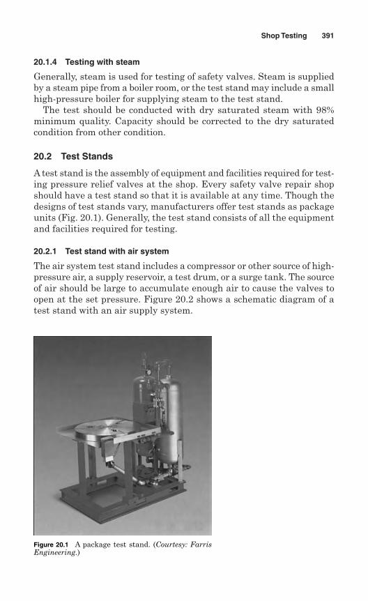
20.1.4 Testing with steam
Generally, steam is used for testing of safety valves. Steam is suppliedby a steam pipe from a boiler room, or the test stand may include a smallhigh-pressure boiler for supplying steam to the test stand.
The test should be conducted with dry saturated steam with 98%minimum quality. Capacity should be corrected to the dry saturatedcondition from other condition.
20.2 Test Stands
A test stand is the assembly of equipment and facilities required for test-ing pressure relief valves at the shop. Every safety valve repair shopshould have a test stand so that it is available at any time. Though thedesigns of test stands vary, manufacturers offer test stands as packageunits (Fig. 20.1). Generally, the test stand consists of all the equipmentand facilities required for testing.
20.2.1 Test stand with air system
The air system test stand includes a compressor or other source of high-pressure air, a supply reservoir, a test drum, or a surge tank. The sourceof air should be large to accumulate enough air to cause the valves toopen at the set pressure. Figure 20.2 shows a schematic diagram of atest stand with an air supply system.
Shop Testing 391
Figure 20.1 A package test stand. (Courtesy: FarrisEngineering.)
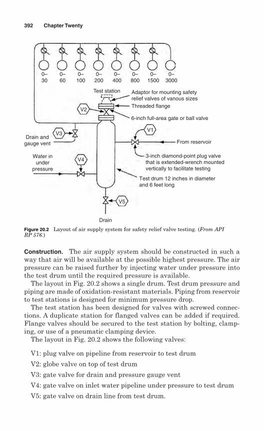
Construction. The air supply system should be constructed in such away that air will be available at the possible highest pressure. The airpressure can be raised further by injecting water under pressure intothe test drum until the required pressure is available.
The layout in Fig. 20.2 shows a single drum. Test drum pressure andpiping are made of oxidation-resistant materials. Piping from reservoirto test stations is designed for minimum pressure drop.
The test station has been designed for valves with screwed connec-tions. A duplicate station for flanged valves can be added if required.Flange valves should be secured to the test station by bolting, clamp-ing, or use of a pneumatic clamping device.
The layout in Fig. 20.2 shows the following valves:
V1: plug valve on pipeline from reservoir to test drum
V2: globe valve on top of test drum
V3: gate valve for drain and pressure gauge vent
V4: gate valve on inlet water pipeline under pressure to test drum
V5: gate valve on drain line from test drum.
392 Chapter Twenty
V2
Test station
V3
V4
V5
V1
From reservoir
3-inch diamond-point plug valvethat is extended-wrench mountedvertically to facilitate testing
Test drum 12 inches in diameterand 6 feet long
Drain
Water inunder
pressure
Drain andgauge vent
6-inch full-area gate or ball valve
Threaded flange
Adaptor for mounting safetyrelief valves of vanous sizes
0–30
0–60
0–100
0–200
0–400
0–800
0–1500
0–3000
Figure 20.2 Layout of air supply system for safety relief valve testing. (From APIRP 576.)
The layout shows eight pressure gauges with the following ranges:
Gauge no. 1: 0–30 psi
Gauge no. 2: 0–60 psi
Gauge no. 3: 0–100 psi
Gauge no. 4: 0–200 psi
Gauge no. 5: 0–400 psi
Gauge no. 6: 0–800 psi
Gauge no. 7: 0–1500 psi
Gauge no. 8: 0–3000 psi
Pressure gauges with additional ranges can be installed if required.
Operation. The operation of the valve test stand is simple. When the teststand is not in use, valves V1, V2, and V5 should be closed. Valve V3should be opened to prevent possible buildup of pressure in the testdrum if valve V1 is leaking.
The test drum should be blown down to remove any accumulation ofdust or sediment. To blow the test drum, close valve V3, open valve V2,and release air through the drum by opening and closing valve V1.Follow the sequence below to test a valve:
Close valve V2. Secure the valve to the test station. Open valve V2. If valve set pressure is lower than available air pressure, slowly
increase pressure through valve V1 until the valve pops. Then close V1. If valve set pressure is higher than available air pressure, open valve
V1 and fill test drum with maximum air pressure available. Thenclose valve V1. Open valve V4 and increase pressure by insertingwater under pressure until valve opens. Then close valve V4 anddrain water from the test drum by opening and closing valve V5.
If necessary, adjust valve spring so that the safety relief valve opensat the required set pressure.
Vent test drum to 90% of set pressure. Test safety relief valve for leakage. After satisfactory test, close valve V2.
Remove the safety relief valve from the test station. Loosen bolts orclamps to allow pressure in the adapter and valve nozzle to escape.
Shop Testing 393
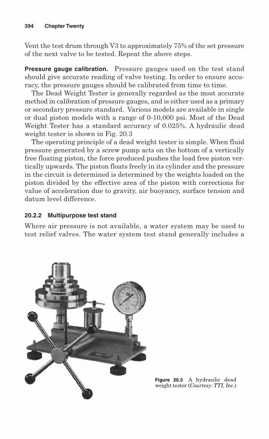
Vent the test drum through V3 to approximately 75% of the set pressureof the next valve to be tested. Repeat the above steps.
Pressure gauge calibration. Pressure gauges used on the test standshould give accurate reading of valve testing. In order to ensure accu-racy, the pressure gauges should be calibrated from time to time.
The Dead Weight Tester is generally regarded as the most accuratemethod in calibration of pressure gauges, and is either used as a primaryor secondary pressure standard. Various models are available in singleor dual piston models with a range of 0-10,000 psi. Most of the DeadWeight Tester has a standard accuracy of 0.025%. A hydraulic deadweight tester is shown in Fig. 20.3
The operating principle of a dead weight tester is simple. When fluidpressure generated by a screw pump acts on the bottom of a verticallyfree floating piston, the force produced pushes the load free piston ver-tically upwards. The piston floats freely in its cylinder and the pressurein the circuit is determined is determined by the weights loaded on thepiston divided by the effective area of the piston with corrections forvalue of acceleration due to gravity, air buoyancy, surface tension anddatum level difference.
20.2.2 Multipurpose test stand
Where air pressure is not available, a water system may be used totest relief valves. The water system test stand generally includes a
394 Chapter Twenty
Figure 20.3 A hydraulic deadweight tester (Courtesy: TTI, Inc.)
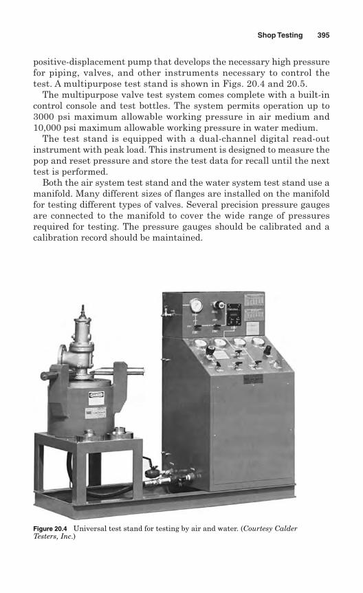
positive-displacement pump that develops the necessary high pressurefor piping, valves, and other instruments necessary to control thetest. A multipurpose test stand is shown in Figs. 20.4 and 20.5.
The multipurpose valve test system comes complete with a built-incontrol console and test bottles. The system permits operation up to3000 psi maximum allowable working pressure in air medium and10,000 psi maximum allowable working pressure in water medium.
The test stand is equipped with a dual-channel digital read-outinstrument with peak load. This instrument is designed to measure thepop and reset pressure and store the test data for recall until the nexttest is performed.
Both the air system test stand and the water system test stand use amanifold. Many different sizes of flanges are installed on the manifoldfor testing different types of valves. Several precision pressure gaugesare connected to the manifold to cover the wide range of pressuresrequired for testing. The pressure gauges should be calibrated and acalibration record should be maintained.
Shop Testing 395
Figure 20.4 Universal test stand for testing by air and water. (Courtesy CalderTesters, Inc.)
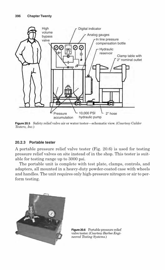
20.2.3 Portable tester
A portable pressure relief valve tester (Fig. 20.6) is used for testingpressure relief valves on site instead of in the shop. This tester is suit-able for testing range up to 3000 psi.
The portable unit is complete with test plate, clamps, controls, andadapters, all mounted in a heavy-duty powder-coated case with wheelsand handles. The unit requires only high-pressure nitrogen or air to per-form testing.
396 Chapter Twenty
Highvolumebypassvalve
Digital indicator
Analog gaugesIn line pressurecompensation bottle
Hydraulicreservoir
Clamp table with2" nominal outlet
2" hose10,000 PSIhydraulic pump
Pressureaccumulation
Figure 20.5 Safety relief valve air or water tester—schematic view. (Courtesy CalderTesters, Inc.)
Figure 20.6 Portable pressure reliefvalve tester. (Courtesy Barbee Engi-neered Testing Systems.)
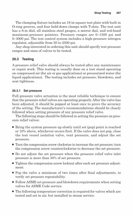
The clamping fixture includes an 18-in-square test plate with built inO-ring grooves, and four hold-down clamps with T-slots. The test unithas a 6-in dial, all stainless steel gauges, a mirror dial, and red-handmaximum-pressure pointers. Pressure ranges are 0–1500 psi and0–3000 psi. The test control system includes a high-pressure nitrogenregulator, adjustable from 50 to 2500 psi.
Any shop interested in ordering this unit should specify test pressureranges and sizes of valves to be tested.
20.3 Testing
A pressure relief valve should always be tested after any maintenanceor repair work. This testing is usually done on a test stand operatingon compressed air (for air or gas applications) or pressurized water (forliquid applications). The testing includes set pressure, blowdown, andseat tightness.
20.3.1 Set pressure
Full pressure valve actuation is the most reliable technique to ensurethat the pressure relief valves are operating properly. After the valve hasbeen adjusted, it should be popped at least once to prove the accuracyof the setting. The manufacturer’s recommendations should be closelyfollowed when setting pressure of any pressure relief valve.
The following steps should be followed in setting the pressure on pres-sure relief valves:
Bring the system pressure up slowly until set (pop) point is reachedor 10% above, whichever occurs first. If the valve does not pop, closethe test vessel isolation valve, vent pressure, and adjust the setpressure.
Turn the compression screw clockwise to increase the set pressure; turnthe compression screw counterclockwise to decrease the set pressure.
Do not adjust the set pressure when the pressure relief valve inletpressure is more than 50% of set pressure.
Tighten the compression screw locknut after each set pressure adjust-ment.
Pop the valve a minimum of two times after final adjustments, toverify set pressure repeatability.
Follow ASME set pressure and blowdown requirements when settingvalves for ASME Code service.
The following temperature correction is required for valves which aretested and set in air, but installed in steam service:
Shop Testing 397
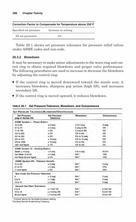
Correction Factor to Compensate for Temperature above 250°F
Specified set pressure Increase in setting
All set pressures 5%
Table 20.1 shows set pressure tolerance for pressure relief valvesunder ASME codes and non-code.
20.3.2 Blowdown
It may be necessary to make minor adjustments to the warn ring and con-trol ring to obtain required blowdown and proper valve performance.The following procedures are used to increase or decrease the blowdownby adjusting the control ring:
If the control ring is moved downward toward the nozzle seat, itincreases blowdown, sharpens pop action (high lift), and increasessecondary lift.
If the control ring is moved upward, it reduces blowdown.
398 Chapter Twenty
TABLE 20.1 Set Pressure Tolerance, Blowdown, and Overpressure
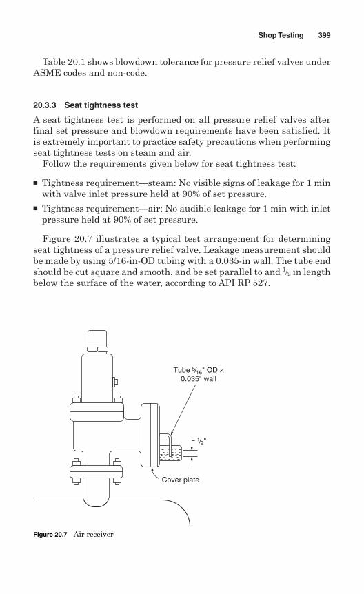
Table 20.1 shows blowdown tolerance for pressure relief valves underASME codes and non-code.
20.3.3 Seat tightness test
A seat tightness test is performed on all pressure relief valves afterfinal set pressure and blowdown requirements have been satisfied. Itis extremely important to practice safety precautions when performingseat tightness tests on steam and air.
Follow the requirements given below for seat tightness test:
Tightness requirement—steam: No visible signs of leakage for 1 minwith valve inlet pressure held at 90% of set pressure.
Tightness requirement—air: No audible leakage for 1 min with inletpressure held at 90% of set pressure.
Figure 20.7 illustrates a typical test arrangement for determiningseat tightness of a pressure relief valve. Leakage measurement shouldbe made by using 5/16-in-OD tubing with a 0.035-in wall. The tube endshould be cut square and smooth, and be set parallel to and 1/2 in lengthbelow the surface of the water, according to API RP 527.
Shop Testing 399
Cover plate
1/2"
Tube 5/16" OD ×0.035" wall
Figure 20.7 Air receiver.
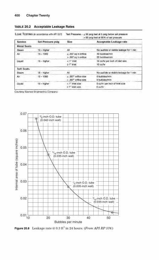
400 Chapter Twenty
TABLE 20.2 Acceptable Leakage Rates
20100.01
0.02
0.03
0.04
Inte
rnal
are
a of
tube
(sq
uare
inch
es)
0.05
0.06
0.07
30Bubbles per minute
40 50
3/8-inch O.D. tube(0.042-inch wall)
5/16-inch O.D. tube(0.035-inch wall)
1/4-inch O.D. tube(0.035-inch wall)
3/10-inch O.D. tube(0.035-inch wall)
Figure 20.8 Leakage rate @ 0.3 ft3 in 24 hours. (From API RP 576.)
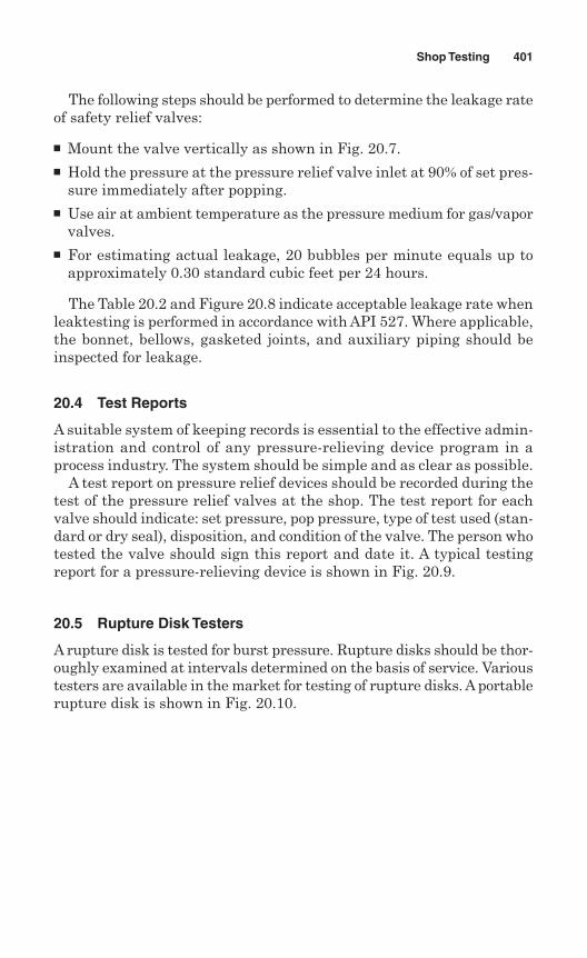
The following steps should be performed to determine the leakage rateof safety relief valves:
Mount the valve vertically as shown in Fig. 20.7. Hold the pressure at the pressure relief valve inlet at 90% of set pres-
sure immediately after popping. Use air at ambient temperature as the pressure medium for gas/vapor
valves. For estimating actual leakage, 20 bubbles per minute equals up to
approximately 0.30 standard cubic feet per 24 hours.
The Table 20.2 and Figure 20.8 indicate acceptable leakage rate whenleaktesting is performed in accordance with API 527. Where applicable,the bonnet, bellows, gasketed joints, and auxiliary piping should beinspected for leakage.
20.4 Test Reports
A suitable system of keeping records is essential to the effective admin-istration and control of any pressure-relieving device program in aprocess industry. The system should be simple and as clear as possible.
A test report on pressure relief devices should be recorded during thetest of the pressure relief valves at the shop. The test report for eachvalve should indicate: set pressure, pop pressure, type of test used (stan-dard or dry seal), disposition, and condition of the valve. The person whotested the valve should sign this report and date it. A typical testingreport for a pressure-relieving device is shown in Fig. 20.9.
20.5 Rupture Disk Testers
A rupture disk is tested for burst pressure. Rupture disks should be thor-oughly examined at intervals determined on the basis of service. Varioustesters are available in the market for testing of rupture disks. A portablerupture disk is shown in Fig. 20.10.
Shop Testing 401
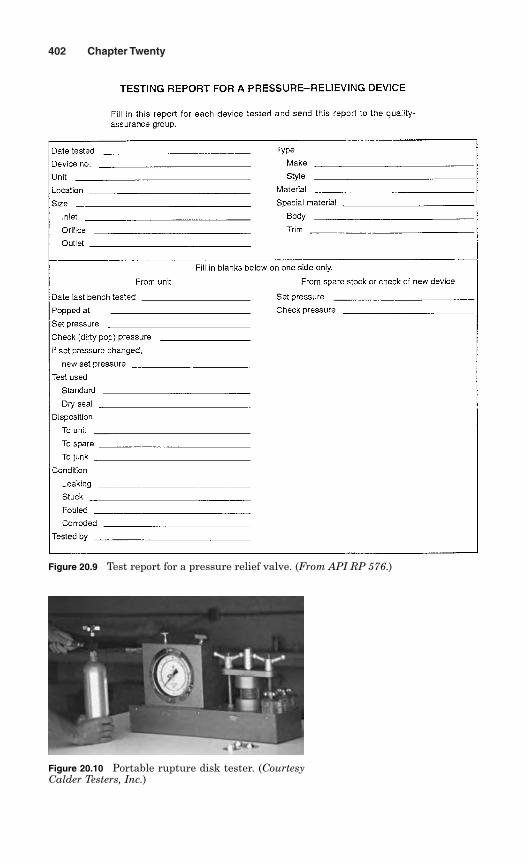
402 Chapter Twenty
Figure 20.9 Test report for a pressure relief valve. (From API RP 576.)
Figure 20.10 Portable rupture disk tester. (CourtesyCalder Testers, Inc.)
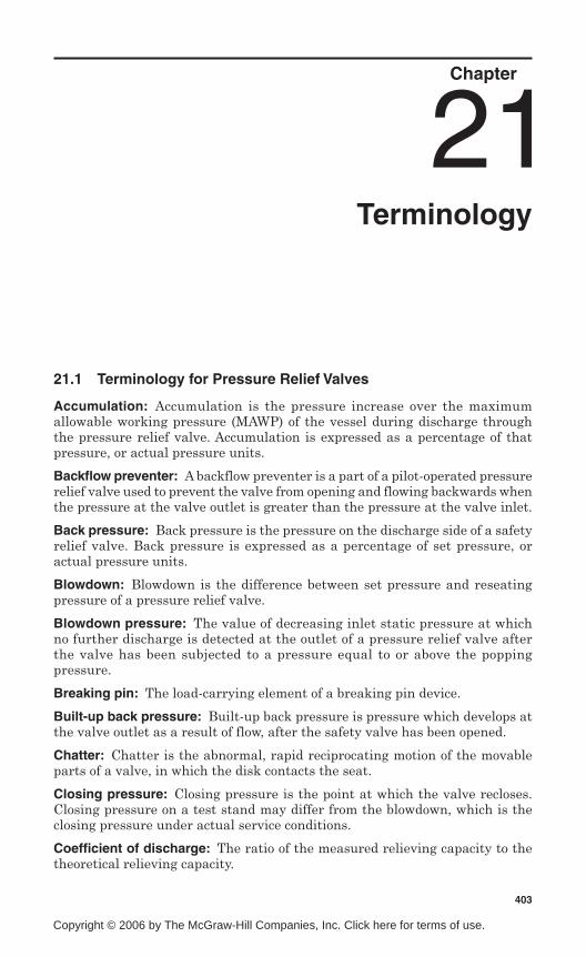
Chapter
Terminology
21.1 Terminology for Pressure Relief Valves
Accumulation: Accumulation is the pressure increase over the maximumallowable working pressure (MAWP) of the vessel during discharge throughthe pressure relief valve. Accumulation is expressed as a percentage of thatpressure, or actual pressure units.
Backflow preventer: A backflow preventer is a part of a pilot-operated pressurerelief valve used to prevent the valve from opening and flowing backwards whenthe pressure at the valve outlet is greater than the pressure at the valve inlet.
Back pressure: Back pressure is the pressure on the discharge side of a safetyrelief valve. Back pressure is expressed as a percentage of set pressure, oractual pressure units.
Blowdown: Blowdown is the difference between set pressure and reseatingpressure of a pressure relief valve.
Blowdown pressure: The value of decreasing inlet static pressure at whichno further discharge is detected at the outlet of a pressure relief valve afterthe valve has been subjected to a pressure equal to or above the poppingpressure.
Breaking pin: The load-carrying element of a breaking pin device.
Built-up back pressure: Built-up back pressure is pressure which develops atthe valve outlet as a result of flow, after the safety valve has been opened.
Chatter: Chatter is the abnormal, rapid reciprocating motion of the movableparts of a valve, in which the disk contacts the seat.
Closing pressure: Closing pressure is the point at which the valve recloses.Closing pressure on a test stand may differ from the blowdown, which is theclosing pressure under actual service conditions.
Coefficient of discharge: The ratio of the measured relieving capacity to thetheoretical relieving capacity.
403
21
Copyright © 2006 by The McGraw-Hill Companies, Inc. Click here for terms of use.
Cold differential test pressure (CDTP): The inlet static pressure at which apressure relief valve is adjusted to open on the test stand. This test pressureincludes corrections for service conditions of superimposed back pressure and/ortemperature.
Constant back pressure: A superimposed back pressure which is constantwith time.
Differential between operating and set pressures: The operating pressureshould not exceed 90% of the set pressure. It is recommended that the valve beset as high above the operating pressure as possible.
Flutter: Flutter is abnormal, rapid reciprocating motion of the movable partsof a valve, in which the disk does not contact the seat.
Leak test pressure: The specified inlet static pressure at which a quantitativeseat leakage test is performed in accordance with a standard procedure.
Lift: Lift is the actual travel of the disk away from the closed position when avalve is relieving.
Maximum allowable working pressure: Maximum allowable working pressure(MAWP) is the maximum gauge pressure permissible in a vessel at a designatedtemperature. It is the highest pressure at which the primary safety relief valveis set.
Operating pressure: Operating pressure is the gauge pressure to which thevessel is normally subjected during operation.
Opening pressure: The value of increasing inlet static pressure of a pressurerelief valve at which there is a measurable lift, or at which the discharge becomescontinuous as determined by seeing, feeling, or hearing.
Overpressure: Overpressure is a pressure increase over the set pressure ofthe primary relieving service. Generally, overpressure is expressed as apercentage of set pressure.
Popping pressure: The value of increasing inlet static pressure at which thedisk moves in the opening direction at a faster rate as compared withcorresponding movement at higher or lower pressures.
Primary pressure: The pressure at the inlet in a pressure relief valve.
Rated capacity: Rated capacity is the percentage of measured flow at anauthorized percent overpressure submitted by the applicable code. Ratedcapacity is expressed in:
pounds per hour (lb/hr) or kilograms per hour (kg/h) for vapor; standard cubic feet per minute (scfm) or normal cubic meters per minute
(lncm/min) or m3/min for gases; and gallons per minute (gpm) or liters per minute (L/min) for liquids.
Resealing pressure: The value of decreasing inlet static pressure at which nofurther leakage is detected after closing.
Seat tightness pressure: Seat tightness pressure is the specified inlet staticpressure at which a quantitative seat leakage test is performed in accordancewith a standard procedure.
404 Chapter Twenty One
Secondary pressure: The pressure existing in the passage between the actualdischarge area and the valve outlet in a safety, safety relief, or relief valve.
Set pressure: Set pressure is the gauge pressure at the valve inlet, for whichthe safety relief valve has been adjusted to open under service conditions. Inliquid service, the inlet pressure at which the valve starts to dischargedetermines set pressure. In gas or vapor service, the inlet pressure at which thevalve pops determines the set pressure.
Simmer: Simmer is characterized by the audible passage of a gas or vaporacross the seating surfaces just prior to “pop.” The difference between this“start-to-open pressure” and set pressure is simmer. Generally, simmer isexpressed as a percentage of set pressure.
Superimposed back pressure: Superimposed back pressure is the pressure inthe discharge header before the safety valve opens. There are two types ofsuperimposed back pressure:
Constant superimposed. This type of back pressure remains essentially ata fixed value (constant) and exists (superimposed) continuously prior to andduring opening of the valve. (e.g., 20 psig/1.38 bar).
Variable superimposed. This type of back pressure varies or changes over arange from a minimum to a maximum, or vice versa. (e.g., 0 to 20 psig/1.38 bar).The actual back pressure at any specific time depends on conditions in thepiping system to which the outlet of the valve is connected.
Valve trim: Valve trim includes the nozzle and disk.
21.2 Terminology for Rupture Disks
Burst pressure: The burst pressure is the inlet static pressure at which arupture disk device functions.
Knife blade: A component with multiple blades used with reverse-acting rupturedisks to cut the disk when it reverses.
Lot of rupture disks: A lot of rupture disks are those disks manufactured of amaterial at the same time, and of the same size, thickness, type, heat, andmanufacturing process, including heat treatment.
Marked burst pressure: A marked burst pressure is the pressure marked on therupture disk device, or its nameplate, or on the tag of the rupture disk, indicatingthe burst pressure at the coincident disk temperature.
Specified burst pressure: A specified burst pressure is the increasing inlet staticpressure at a specified temperature, at which a rupture disk is designed to function.
Rupture disk: A rupture disk is the pressure-containing element in a rupturedisk device that is designed to burst at its rated pressure at a specifiedtemperature.
Rupture disk holder: A rupture disk holder is the structure which clamps arupture disk in position.
Vacuum support: A vacuum support is a component of a rupture disk to preventflexing due to upstream vacuum or downstream back pressure.
Terminology 405

This page intentionally left blank
Appendix
A1914 ASME Boiler Code*
The following excerpts are reprinted from the first boiler code, “Rulesfor the Construction of Stationary Boilers and for Allowable WorkingPressures” (ASME, New York, 1914).
Part I NEW INSTALLATIONSSection 1 Power Boilers
Safety Valves
269 Safety Valve Requirements. Each boiler shall have two or more safetyvalves, except a boiler for which one safety valve is 3-in. size or smalleris required by these Rules.
270 The safety valve capacity for each boiler shall be such that the safetyvalve or valves will discharge all the steam that can be generated by theboiler without allowing the pressure to rise more than six percent abovethe maximum allowable working pressure, or more than six percent abovethe highest pressure to which any valve is set.
271 One or more safety valves on every boiler shall be set at or below themaximum allowable working pressure. The remaining valves may be setwithin a range of three percent above the maximum allowable workingpressure, but the range of setting of all of the valves on a boiler shall notexceed ten percent of the highest pressure to which any valve is set.
272 Safety valves shall be of the direct spring loaded pop type with seat andbearing surface of the disc either inclined at an angle of about 45 deg. orflat at an angle of about 90 deg to the center line of spindle. The verticallift of the valve disc measured immediately after sudden lift due to the popmay be made any amount desired up to a maximum of 0.15 in. respective
407
*Courtesy ASME International.
Copyright © 2006 by The McGraw-Hill Companies, Inc. Click here for terms of use.
of the size of the valve. The nominal diameter measured at the inner edgeof the valve seat shall be not less than 1 in. or more than 41/2 in.
273 Each safety valve shall have plainly stamped or cast on the body:a The name or identifying trade-mark of the manufacturerb The nominal diameter with the words “Bevel Seat” or “Flat Seat”c The steam pressure at which it is set to blowd The lift of the valve disc from its seat, measured immediately after
sudden lift due to the pope The weight of steam discharged in pounds per hour at the pressure for
which it is set to blow.
274 The minimum capacity of a safety valve or valves to be placed on a boilershall be determined on the basis of 6 lb. of steam per hour per sq. ft. ofboiler heating surface for water tube boilers, and 5 lb. for all other typesof power boilers, and upon the relieving capacity marked on the valves bythe manufacturer, provided such marked relieving capacity does notexceed that given in Table 8. In case the relieving capacity marked on thevalve or valves exceeds the maximum given in Table 8, the minimumsafety valve capacity shall be determined on the basis of the maximumrelieving capacity given in Table 8 for the particular size of valve andworking pressure for which it was constructed. The heating surface shallbe computed for that side of the boiler surface exposed to the products ofcombustion, exclusive of the superheating surface. In computing the heat-ing surface for this purpose only the tubes, shells, tube sheet and the pro-jected area of headers need be considered.
275 Safety valve capacity may be checked in any one of three different ways,and if found sufficient, additional capacity need not be provided: a By making an accumulation test, by shutting off all other steam dis-
charge outlets from the boiler and forcing the fires to the maximum.The safety valve equipment shall be sufficient to prevent an excesspressure beyond six per cent as specified in Par. 270.
b By measuring the maximum amount of fuel that can be burned andcomputing the corresponding evaporative capacity upon the basis of theheating value of the fuel.
c By determining the maximum evaporative capacity by measuring thefeed water. The sum of the safety valve capacities marked on the valves,shall be equal to or greater than the maximum evaporative capacityof the boiler.
276 When tow or more safety valves are used on a boiler, they may be eitherseparate or twin valves made by mounting individual valves on Y-bases, or duplex, triplex or multiplex valves having two or more valves in thesame body casing.
277 The safety valve or valves shall be connected to the boiler independent ofany other steam connection, and attached as close as possible to the boiler,without any unnecessary intervening pipe or fitting. Every safety valveshall be connected so as to stand in an up right position, with spindle ver-tical, when possible.
408 Appendix A
278 Each safety valve shall have full sized direct connection to the boiler. Novalve of any description shall be placed between the safety valve and theboiler, nor on the discharge pipe between the safety valve and the atmos-phere. When a discharge pipe is used, it shall be not less than the full sizeof the valve, and shall be fitted with an open drain to prevent water fromlodging in the upper part of the safety valve or in the pipe.
279 If a muffler is used on a safety valve it shall have sufficient outlet area toprevent back pressure from interfering with the proper operation and dis-charge capacity of the valve. The muffler plates or other devices shall be soconstructed that as to avoid any possibility of restriction of the steam pas-sage due to deposit. When an elbow is placed on a safety valve dischargepipe, it shall be located close to the safety valve outlet or the pipe shall besecurely anchored and supported. All safety valve discharges shall be locatedor piped as to be carried clear from running boards or working platformsused in controlling the main stop valves of boilers or steam headers.
280 When a boiler is fitted with two or more safety valves on one connection,this connection to the boiler shall have a cross-sectional area not lessthan the combined area of all of the safety valves with which it connects.
281 Safety valves should operate without chattering and shall be set andadjusted as follows: To close after blowing down not more than 4 lb. on boil-ers carrying an allowed pressure less than 100 lb. per sq. in gage. To closeafter blowing down not more than 6 lb. on boilers carrying pressuresbetween 100 and 200 lb. per sq. in. gage inclusive. To close after blowingdown not more than 8 lb. on boilers carrying over 200 lb. per sq. in. gage.
282 Each safety valve used on a boiler shall have a substantial lifting device,and shall have the spindle so attached that the valve disc can be lifted fromits seat a distance not less than one-tenth of the nominal diameter of thevalve, when there is no pressure on the boiler.
283 The seats and discs of safety valves shall be of non-ferrous material.
284 Springs used in safety valves shall not show a permanent set exceeding1/32 in. ten minutes after being released from a cold compression test clos-ing the spring solid.
285 The spring in a safety valve shall not be used for any pressure more than10 percent above or below that for which it was designed.
286 A safety valve over 3-in. size, used for pressures greater than 15 lb. per sq.in. gage, shall have a flanged inlet connection. The dimensions of the flangesshall conform to the American standard in Tables 15 and 16 of the Appendix.
287 When the letters A S M E Std are plainly stamped or cast on the valvebody this shall be a guarantee by the manufacturer that the valve con-forms with the details of construction herein specified.
288 Every superheater shall have one or more safety valves near the outlet.The discharge capacity of the safety valve or valves on an attached super-heater may be included in determining the number and sizes of the safetyvalves for the boiler, provided there are no intervening valves between thesuperheater safety valve and the boiler.
1914 ASME Boiler Code 409
289 Every safety valve used on a superheater, discharging superheated steam,shall have a steel body with a flanged inlet connection, and shall have theseat and disc of nickel composition or equivalent material, and the springfully exposed outside of the valve casing so that it shall be protected fromcontact with the escaping steam.
290 Every boiler shall have proper outlet connections for the required safetyvalve or valves, independent of any other steam outlet connection of anyinternal pipe in the steam space of the boiler, the area of opening to be atleast equal to the aggregate area of all of the safety valves to attach thereto.
Section 2 Heating Boilers
347 Outlet connections for safety and Water Relief Valves. Every boiler shallhave proper outlet connections for the required safety, or water reliefvalve or valves, independent of any other connection outside of the boileror any internal pipe in the boiler, the area of the opening to be at leastequal to the aggregate area of all of the safety valves with which it con-nects. A screwed connection may be used for attaching a safety valve to aheating boiler. This rule applies to all sizes of safety valves.
348 Safety Valves. Each steam boiler shall be provided with one or more safetyvalves of the spring-pop type which cannot be adjusted to a higher pres-sure than 15 lb. per sq. in.
349 Water Relief Valves. Each hot water boiler shall be provided with one ormore relief valves with open discharges having outlets in plain sight.
350 A hot-water boiler built for a maximum allowable working pressure of30 lb. per sq. in. and used exclusively for heating buildings, or for hot-water supply, shall be provided with a water relief valve or valves, whichcannot be adjusted for a pressure in excess of 30 lb. per. sq. in.
351 No safety or water relief valve shall be smaller than 1 in. nor greaterthan 41/2 in. nominal size.
352 When two or more safety or water relief valves are used on a boiler theymay be single or twin valves.
353 Safety or water relief valves shall be connected to boilers independent ofother connections and be attached directly or as close as possible to theboiler, without any intervening pipe or fittings except the Y-base forminga part of the twin valve or the shortest possible connection. A safety orwater relief valve shall not be connected to an internal pipe in the boiler.Safety valves shall be connected so as to stand upright, with the spindlevertical, when possible.
354 No shut-off of any description shall be placed between the safety or waterrelief valves and boilers, nor on discharge pipes between them and theatmosphere.
355 When a discharge pipe is used its area shall be not less than the area ofthe valve on aggregate area of the valves with which it connects, and the
410 Appendix A
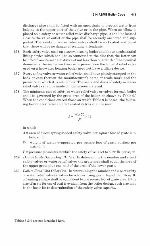
discharge pipe shall be fitted with an open drain to prevent water fromlodging in the upper part of the valve or in the pipe. When an elbow isplaced on a safety or water relief valve discharge pipe, it shall be locatedclose to the valve outlet or the pipe shall be securely anchored and sup-ported. The safety or water relief valves shall be so located and pipedthat there will be no danger of scalding attendants.
356 Each safety valve used on a steam heating boiler shall have a substantiallifting device which shall be so connected to the disc that the latter canbe lifted from its seat a distance of not less than one-tenth of the nominaldiameter of the seat when there is no pressure on the boiler. A relief valveused on a hot-water heating boiler need not have a lifting device.
357 Every safety valve or water relief valve shall have plainly stamped on thebody or cast thereon the manufacturer’s name or trade mark and thepressure at which it is set to blow. The seats and discs of safety or waterrelief valves shall be made of non-ferrous material.
358 The minimum size of safety or water relief valve or valves for each boilershall be governed by the grate area of the boiler, as shown by Table 9.∗
When the conditions exceed those on which Table 9 is based, the follow-ing formula for bevel and flat seated valves shall be used:
in which
A = area of direct spring-loaded safety valve per square foot of grate sur-face, sq. in.
W = weight of water evaporated per square foot of grate surface persecond, lb.
P = pressure (absolute) at which the safety valve is set to blow, lb. per sq. in.
359 Double Grate Down Draft Boilers. In determining the number and size ofsafety valves or water relief valves the grate area shall equal the area ofthe upper grate plus one-half of the area of the lower grate.
360 Boilers Fired With Oil or Gas. In determining the number and size of safetyor water relief valve or valves for a boiler using gas or liquid fuel, 15 sq. ft.of heating surface shall be equivalent to one square foot of grate area. If thesize of grate for use of coal is evident from the boiler design, such size maybe the basis for te determination of the safety valve capacity.
AW
P= × ×70
11
1914 ASME Boiler Code 411
∗Tables 8 & 9 are not furnished here.

This page intentionally left blank
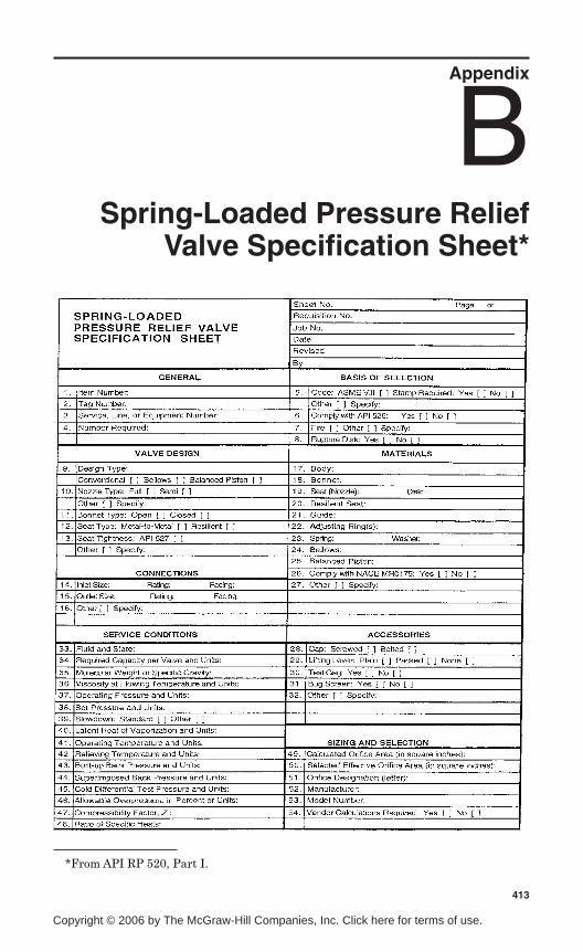
Appendix
BSpring-Loaded Pressure Relief
Valve Specification Sheet*
413
*From API RP 520, Part I.
Copyright © 2006 by The McGraw-Hill Companies, Inc. Click here for terms of use.

This page intentionally left blank
Appendix
CPilot-Operated Pressure Relief
Valve Specification Sheet*
*From API RP 520, Part I.
Copyright © 2006 by The McGraw-Hill Companies, Inc. Click here for terms of use.
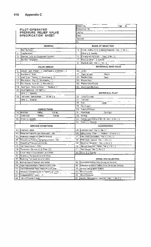
416 Appendix C
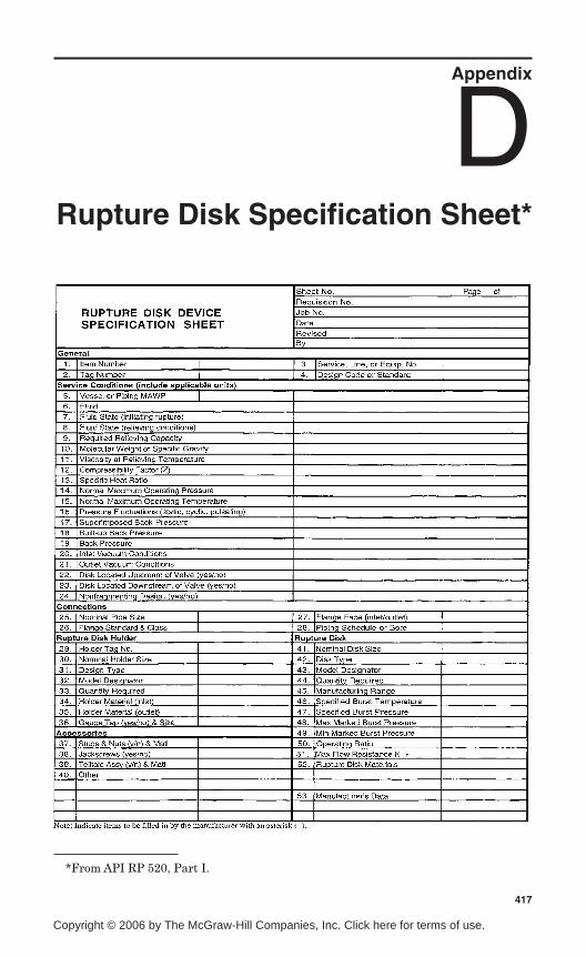
Appendix
DRupture Disk Specification Sheet*
417
*From API RP 520, Part I.
Copyright © 2006 by The McGraw-Hill Companies, Inc. Click here for terms of use.

This page intentionally left blank
Appendix
EASME Applicationfor Accreditation*
*Courtesy ASME International.
Copyright © 2006 by The McGraw-Hill Companies, Inc. Click here for terms of use.
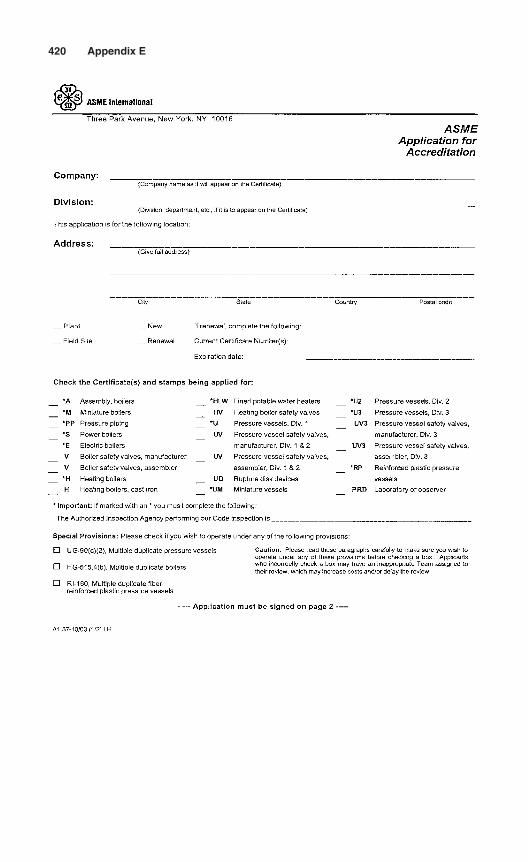
420 Appendix E
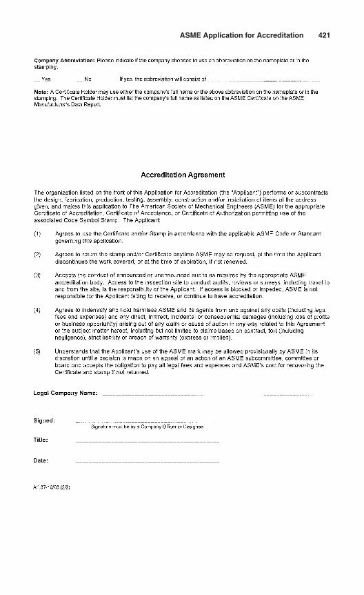
ASME Application for Accreditation 421
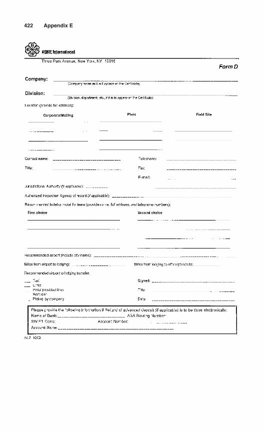
422 Appendix E
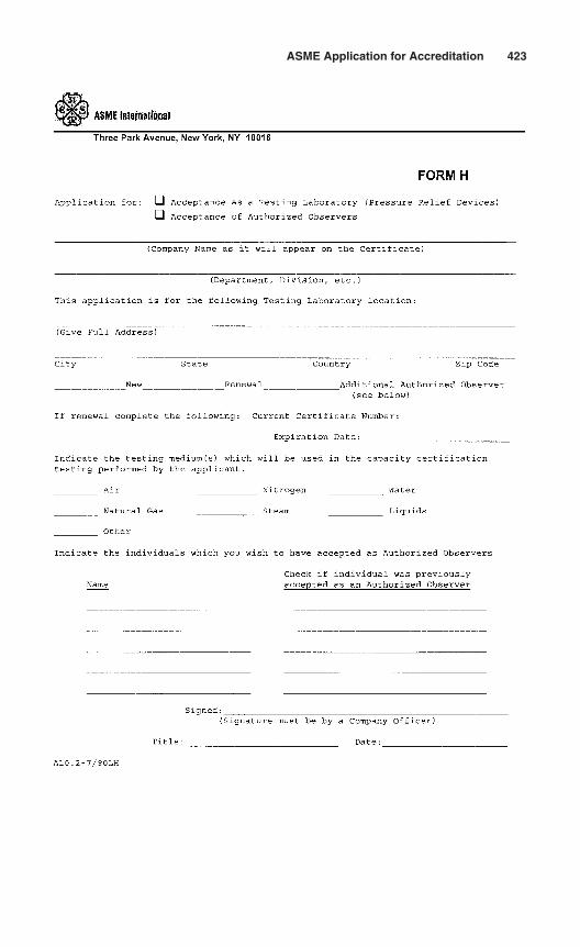
ASME Application for Accreditation 423

This page intentionally left blank

Appendix
FASME-Accredited Testing
Laboratories*
*Courtesy ASME International.
Copyright © 2006 by The McGraw-Hill Companies, Inc. Click here for terms of use.
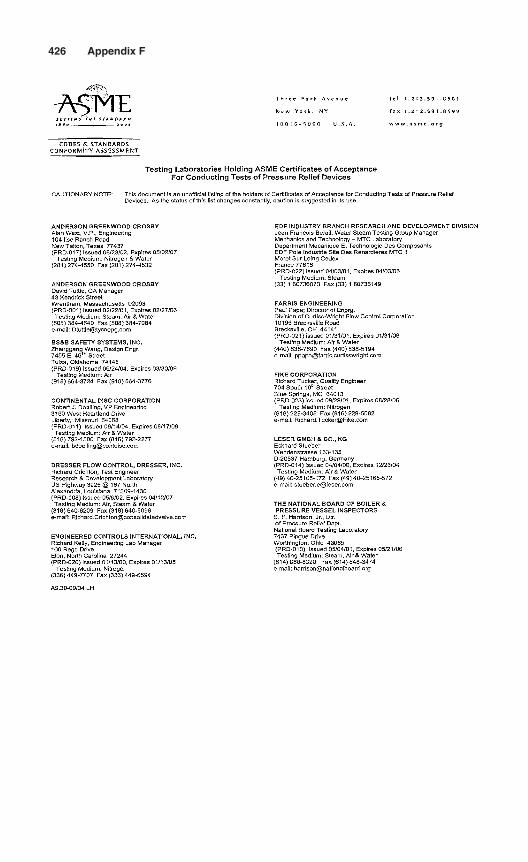
426 Appendix F

Appendix
GPhysical Properties
of Gas or Vapor
Copyright © 2006 by The McGraw-Hill Companies, Inc. Click here for terms of use.
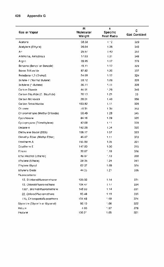
428 Appendix G
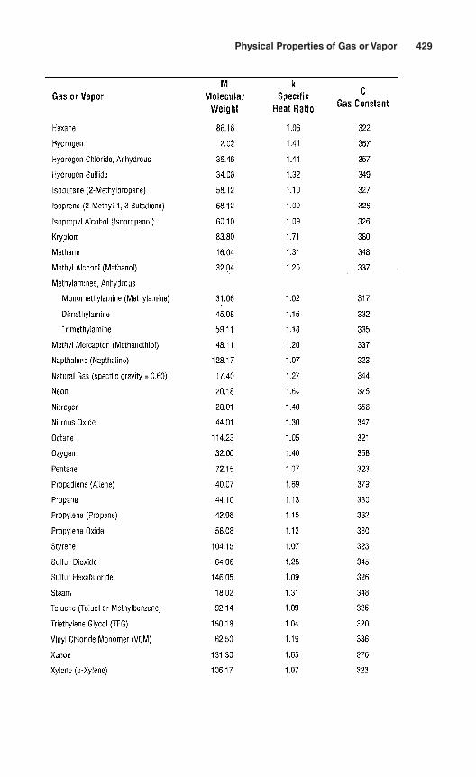
Physical Properties of Gas or Vapor 429

This page intentionally left blank
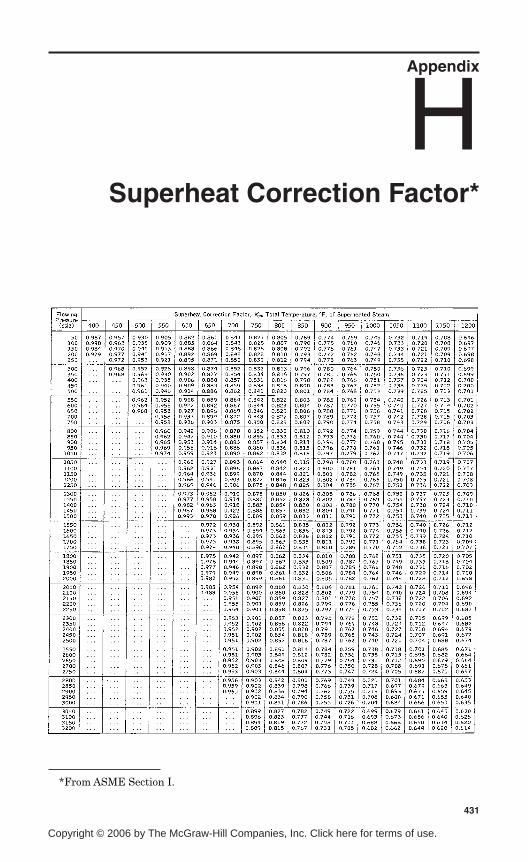
Appendix
HSuperheat Correction Factor*
431
*From ASME Section I.
Copyright © 2006 by The McGraw-Hill Companies, Inc. Click here for terms of use.
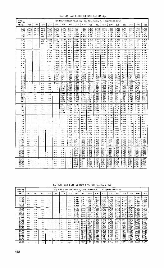
432
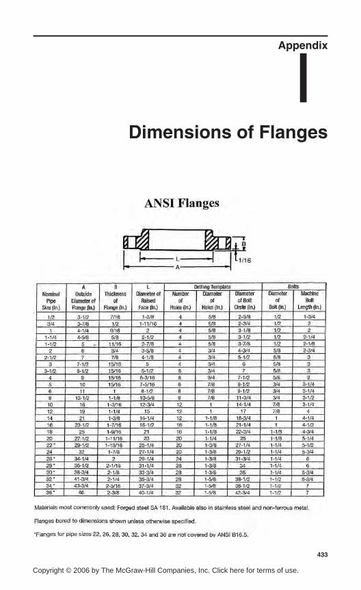
Appendix
IDimensions of Flanges
433
ΑΝΣΙ Φλανγεσ
Copyright © 2006 by The McGraw-Hill Companies, Inc. Click here for terms of use.
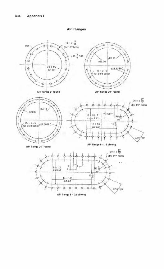
434 Appendix I
f12
f30.00f24.19
f27.50 B.C.
B ± 1/2cut out
10 ± 1/2cut out
14 ± 1/2cut out
f 1038
B.C.
f 8 ± 1/2cut out 16 × f .75
(for f 5/8 bolts)
20 × f .75(for f 5/8 bolts)
16 × f 1732
(for 1/2" bolts)
API Flanges
26 × f 1732
(for 1/2" bolts)
30 × f 1732
(for 1/2" bolts)
f23.50 B.C.
f26.00f20.19
12
8 ± 1/2cut out
12
2 typ.
2 typ.
10 3–8
10 3–8
22.5° typ.
22.5° typ.
R5 316
typ.
R5 316
typ.
API flange 8" round
API flange 24" roundAPI flange 8 × 18 oblong
API flange 8 × 22 oblong
API flange 20" round
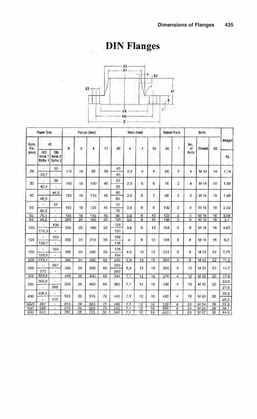
Dimensions of Flanges 435
∆ΙΝ Φλανγεσ
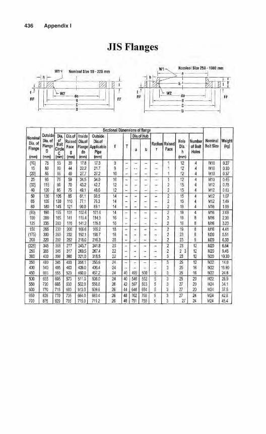
436 Appendix I
ϑΙΣ Φλανγεσ
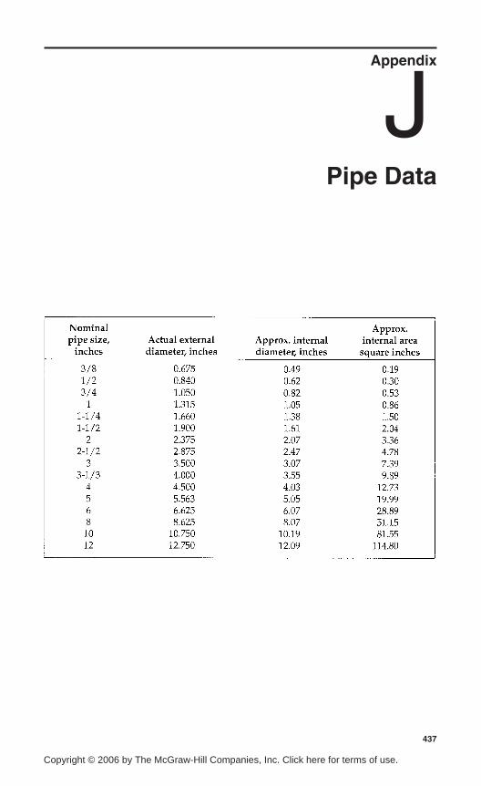
Appendix
JPipe Data
437
Copyright © 2006 by The McGraw-Hill Companies, Inc. Click here for terms of use.

This page intentionally left blank
Appendix
KManufacturer’s Data
Report Form NV-1*
*From ASME Section III, Div. 1.
Copyright © 2006 by The McGraw-Hill Companies, Inc. Click here for terms of use.
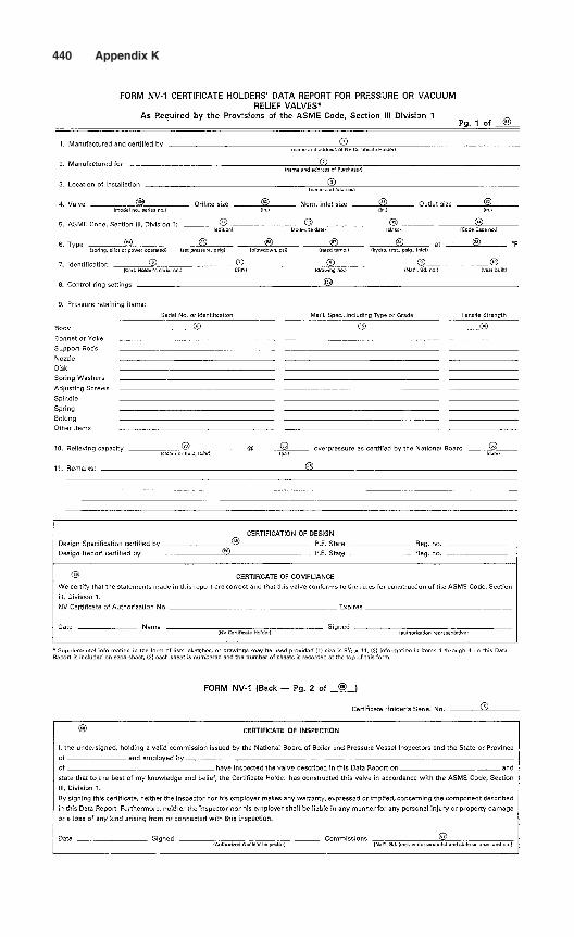
440 Appendix K
Appendix
LCorrosion Resistance Guide
The following chart may be used as a guide for selecting materials forvarious applications. The symbols used in the chart are as floows:
A = Excellent resistance B = Good resistance
C = Fair resistance N = No recommended
Blank space indicates insufficient data.
441
Copyright © 2006 by The McGraw-Hill Companies, Inc. Click here for terms of use.
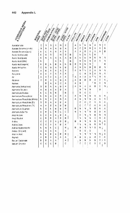
442 Appendix L
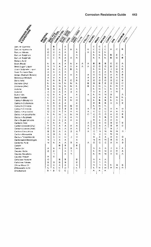
Corrosion Resistance Guide 443
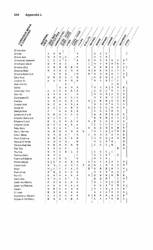
444 Appendix L
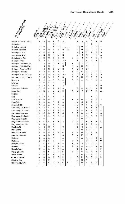
Corrosion Resistance Guide 445
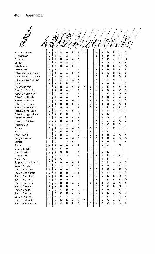
446 Appendix L
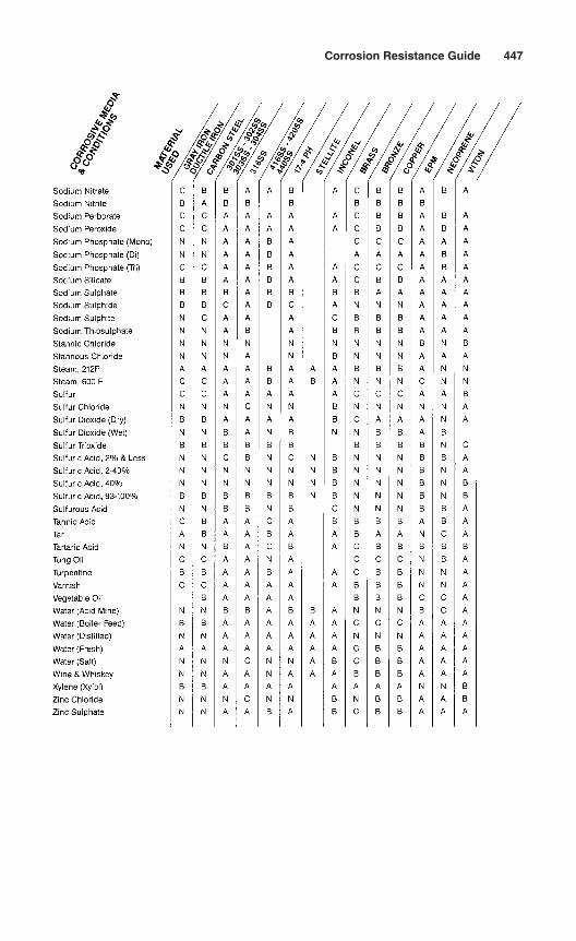
Corrosion Resistance Guide 447

This page intentionally left blank
Appendix
Water Saturation Pressureand Temperature
M
Copyright © 2006 by The McGraw-Hill Companies, Inc. Click here for terms of use.
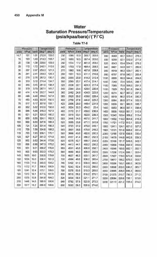
450 Appendix M
waterSaturation Pressure/Temperature
(psia/kpaa/bara)/(F/C)Table T7-8
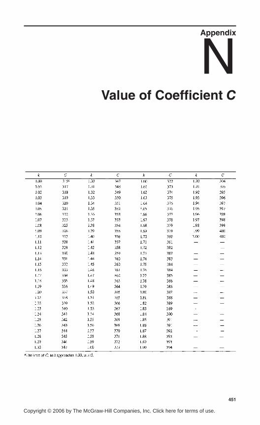
Appendix
NValue of Coefficient C
451
Copyright © 2006 by The McGraw-Hill Companies, Inc. Click here for terms of use.

This page intentionally left blank
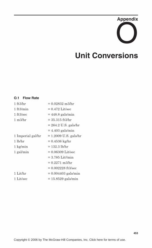
Appendix
OUnit Conversions
O.1 Flow Rate
1 ft3/hr = 0.02832 m3/hr
1 ft3/min = 0.472 Lit/sec
1 ft3/sec = 448.8 gals/min
1 m3/hr = 35.315 ft3/hr
= 264.2 U.S. gals/hr
= 4.403 gals/min
1 Imperial gal/hr = 1.2009 U.S. gals/hr
1 lb/hr = 0.4536 kg/hr
1 kg/min = 132.3 lb/hr
1 gal/min = 0.06309 Lit/sec
= 3.785 Lit//min
= 0.2271 m3/hr
= 0.002228 ft3/sec
1 Lit/hr = 0.004403 gals/min
1 Lit/sec = 15.8529 gals/min
453
Copyright © 2006 by The McGraw-Hill Companies, Inc. Click here for terms of use.
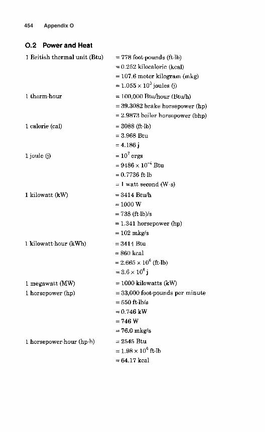
454 Appendix O
O.2 Power and Heat
1 British thermal unit (Btu) = 778 foot-pounds (ft-lb)
= 0.252 kilocalorie (kcal)
= 107.6 meter kilogram (mkg)
= 1.055x 10³ joules (j)
1 therm-hour = 100,000 Btu/hour (Btu/h)
= 39.3082 brake horsepower (hp)
= 2.9873 boiler horsepower (bhp)
1 calorie (cal) = 3088 (ft-lb)
= 3.968 Btu
= 4.186j
1 joule (j) = 107 ergs
= 9486 x 10~4 Btu
= 0.7736 ft-lb= 1 watt second (W-s)
1 kilowatt (kW) = 3414 Btu/h
= 1000 W
= 738 (ft-lb)/s= 1.341 horsepower (hp)
= 102 mkg/s
1 kilowatt-hour (kWh) = 3414 Btu
= 860 kcal
= 2.665 x 10⁶ (ft-lb)
= 3.6xl06j
1 megawatt (MW) = 1000 kilowatts (kW)
1 horsepower (hp) = 33,000 foot-pounds per minute
= 550 ft-lb/s
= 0.746 kW
= 746W
= 76.0 mkg/s
1 horsepower-hour (hp-h) = 2545 Btu
= 1.98 x 106 ft-lb
= 64.17 kcal
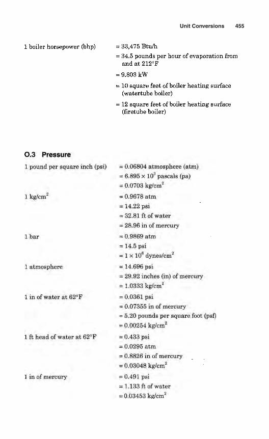
Unit Conversions 455
1 boiler horsepower (bhp) = 33,475 Btu/h= 34.5 pounds per hour of evaporation from
and at 212°F
= 9.803 kW
= 10 square feet of boiler heating surface(watertube boiler)
= 12 square feet of boiler heating surface(firetube boiler)
O.3 Pressure
1 pound per square inch (psi) = 0.06804 atmosphere (atm)= 6,895 x 103 pascals (pa)= 0.0703 kg/cm2
1 kg/cm2 =0.9678 atm= 14.22 psi
= 32.81 ft of water= 28.96 in of mercury
1 bar =0.9869 atm= 14.5 psi= 1 x 10e dynes/cm2
1 atmosphere = 14.696 psi= 29.92 inches (in) of mercury= 1.0333 kg/cm2
1 in of water at 62°F = 0.0361 psi= 0.07355 in of mercury= 5.20 pounds per square foot (psf)
= 0.00254 kg/cm"
1 ft head of water at 62°F = 0.433 psi
= 0,0295 atm= 0.8826 in of mercury
= 0.03048 kg/cm2
1 in of mercury = 0.491 psi- 1.133 ft of water
= 0.03453 kg/cm2
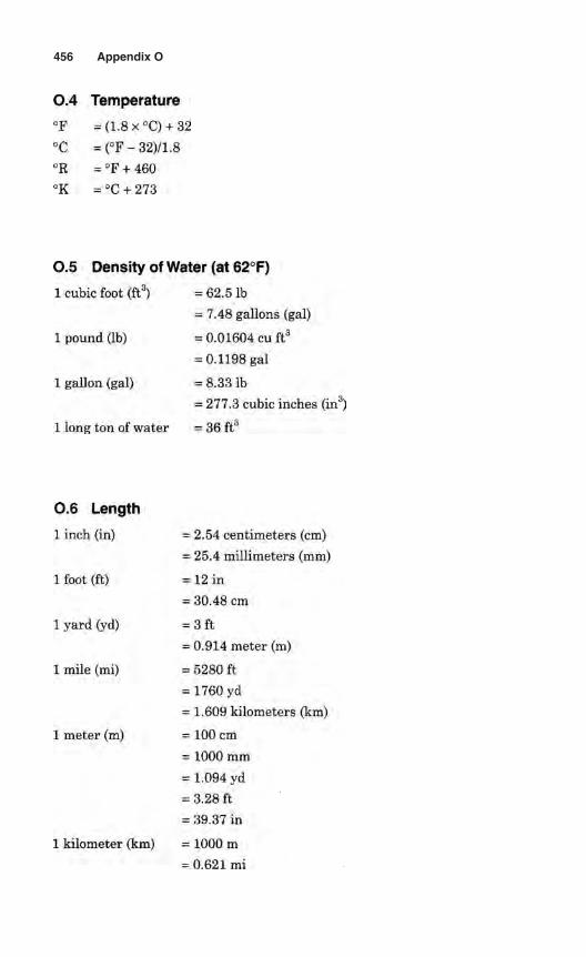
456 Appendix O
O.4 Temperature
°F = (1.8 x °C) + 32
°C =(°F-32)/l,8°R = °F + 460
°R = °C + 273
O.5 Density of Water (at 62°F)
1 cubic foot (ft3) = 62.5 Ib= 7.48 gallons (gal)
1 pound (Ib) = 0.01604 cu ft3
= 0.1198 gal
1 gallon (gal) = 8.33 Ib= 277.3 cubic inches (in3)
1 long ton of water = 36 ft3
O.6 Length
1 inch (in) = 2.54 centimeters (cm)
= 25.4 millimeters (mm)
1 foot (ft) =12 in
= 30.48 cm
1 yard (yd) = 3 ft
= 0.914 meter (m)
1 mile (mi) = 5280 ft
= 1760 yd
= 1.609 kilometers (km)
1 meter (m) = 100cm
= 1000 mm
= 1.094 yd
= 3.28 ft
= 39.37 in
1 kilometer (km) = 1000 m
- 0.621 mi
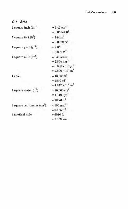
Unit Conversions 457
O.7 Area
1 square inch (in2) = 6.45 cm2
= .006944 ft2
1 square foot (ft2) = 144 in2
= 0.0929 m2
1 square yard (yd2) = 9 ft2
= 0.836 m2
1 square mile (mi2) = 640 acres= 2.590 km2
= 3.098 x 10⁶ yd3
= 2.590 x 10⁶m2
1 acre = 43,560 ft2
= 4840 yd2
= 4.047 x!03m2
1 square meter (m2) = 10,000 cm2
= 11.196yd2
= 10.76 ft2
1 square centimeter (cm2) = 100 mm2
= 0.155 in2
1 nautical mile = 6080 ft= 1.853 km
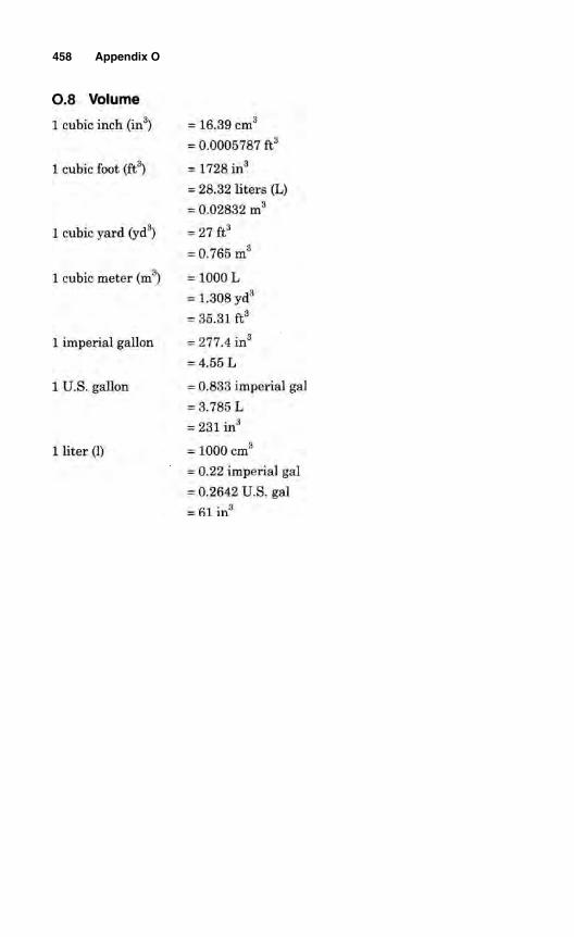
458 Appendix O
O.8 Volume
1 cubic inch (in3) - 16.39 cm3
= 0-0005787 ft3
1 cubic foot (ft3) = 1728 in3
= 28.32 liters (L)= 0,02832 m3
1 cubic yard (yd3) = 27 ft3
= 0.765 m3
1 cubic meter (m3) = 1000 L= 1.308 yd3
= 35.31 ft3
1 imperial gallon = 277.4 in3
= 4,55 L
1 U.S. gallon = 0.833 imperial gal
= 3.785 L= 231 in3
1 liter (1) = 1000 cm3
= 0.22 imperial gal= 0.2642 U.S. gal
= 61 in3
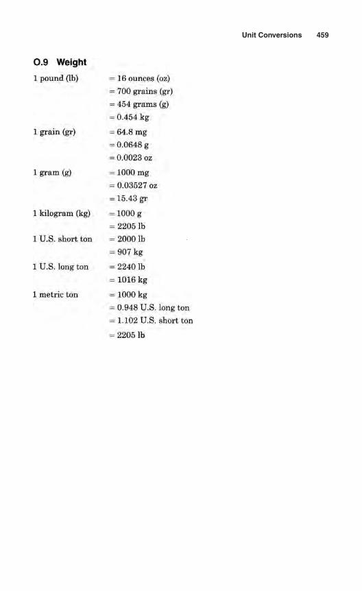
Unit Conversions 459
O.9 Weight
1 pound (Ib) = 16 ounces (oz)= 700 grains (gr)= 454 grams (g)
= 0.454 kg
1 grain gr) = 64.8 mg= 0.0648 g
= 0.0023 oz
1 gram (g) = 1000 mg= 0.03527 02
= 15.43 gr
1 kilogram (kg) = 1000 g
= 2205 Ib1 U.S. short ton = 2000 Ib
= 907 kg
1 U.S. long ton = 2240 Ib= Ifl lf ikg
1 metric ton = 1000 kg= 0.948 U.S. long ton
= 1.102 U.S. short ton
= 2205 Ib

This page intentionally left blank
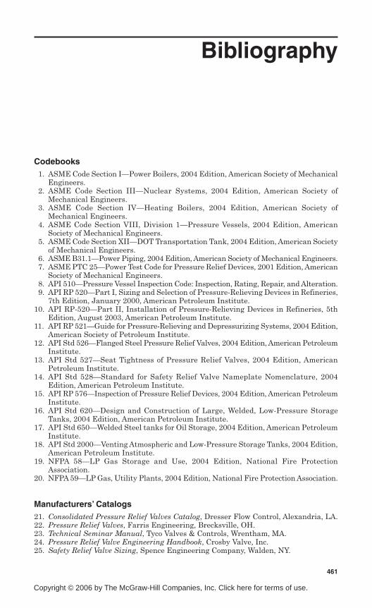
Bibliography
Codebooks1. ASME Code Section I—Power Boilers, 2004 Edition, American Society of Mechanical
Engineers.2. ASME Code Section III—Nuclear Systems, 2004 Edition, American Society of
Mechanical Engineers.3. ASME Code Section IV—Heating Boilers, 2004 Edition, American Society of
Mechanical Engineers.4. ASME Code Section VIII, Division 1—Pressure Vessels, 2004 Edition, American
Society of Mechanical Engineers.5. ASME Code Section XII—DOT Transportation Tank, 2004 Edition, American Society
of Mechanical Engineers.6. ASME B31.1—Power Piping, 2004 Edition, American Society of Mechanical Engineers.7. ASME PTC 25—Power Test Code for Pressure Relief Devices, 2001 Edition, American
Society of Mechanical Engineers.8. API 510—Pressure Vessel Inspection Code: Inspection, Rating, Repair, and Alteration. 9. API RP 520—Part I, Sizing and Selection of Pressure-Relieving Devices in Refineries,
7th Edition, January 2000, American Petroleum Institute.10. API RP-520—Part II, Installation of Pressure-Relieving Devices in Refineries, 5th
Edition, August 2003, American Petroleum Institute.11. API RP 521—Guide for Pressure-Relieving and Depressurizing Systems, 2004 Edition,
American Society of Petroleum Institute.12. API Std 526—Flanged Steel Pressure Relief Valves, 2004 Edition, American Petroleum
Institute.13. API Std 527—Seat Tightness of Pressure Relief Valves, 2004 Edition, American
Petroleum Institute.14. API Std 528—Standard for Safety Relief Valve Nameplate Nomenclature, 2004
Edition, American Petroleum Institute.15. API RP 576—Inspection of Pressure Relief Devices, 2004 Edition, American Petroleum
Institute.16. API Std 620—Design and Construction of Large, Welded, Low-Pressure Storage
Tanks, 2004 Edition, American Petroleum Institute.17. API Std 650—Welded Steel tanks for Oil Storage, 2004 Edition, American Petroleum
Institute.18. API Std 2000—Venting Atmospheric and Low-Pressure Storage Tanks, 2004 Edition,
American Petroleum Institute.19. NFPA 58—LP Gas Storage and Use, 2004 Edition, National Fire Protection
Association.20. NFPA 59—LP Gas, Utility Plants, 2004 Edition, National Fire Protection Association.
Manufacturers’ Catalogs21. Consolidated Pressure Relief Valves Catalog, Dresser Flow Control, Alexandria, LA.22. Pressure Relief Valves, Farris Engineering, Brecksville, OH.23. Technical Seminar Manual, Tyco Valves & Controls, Wrentham, MA.24. Pressure Relief Valve Engineering Handbook, Crosby Valve, Inc. 25. Safety Relief Valve Sizing, Spence Engineering Company, Walden, NY.
461
Copyright © 2006 by The McGraw-Hill Companies, Inc. Click here for terms of use.
26. Bronze Safety Valves, Conbraco Industries, Inc., Matthews, NC.27. Plumbing and Heating Products, Conbraco Industries, Inc., Matthews, NC.28. Safety and Relief Valve Products, Kunkle Valve Company, Stafford, TX.29. Rupture Disc Selection Guide, Continental Disc Corporation, Liberty, MO.30. Rupture Disc, Fike Corporation, Blue Springs, MO.31. Custom Engineered Pressure Relief Devices, Oseco, Inc., Broken Arrow, OK.32. Rupture Disks, Zook USA, Chagrin Falls, OH.33. Rupture Disk Selection Guide, BS&B Safety Systems, Inc., Tulsa, OK.34. Rupture Pin, Rupture Pin Technology, Oklahoma City, OK.35. Buckling Pin, Buckling Pin Technology, Oklahoma City, OK.
Other References36. Introduction to Safety Valves, Spirax Sarco, U.K.37. Electronic Relief Valves, Valvtechnologies, Inc., Houston, TX.38. Pressure Relief Valves, Midland Manufacturing Corp., Skokie, IL.39. Nuclear Valve Resource Guide, CCI Switzerland.40. Pressure/Vacuum Relief Valves, Enardo, Inc., Tulsa, OK.41. Valve Repair Machine, Climax Portable Machine Tools, Inc., Newberg, OR.42. High Performance Valve Testing Equipment, Calder Testers, Inc., Houston, TX.43. Trailer Tanks, Chart-Ferox, Germany.44. Valve World, a valve magazine published from the Netherlands.45. The Engineering Tool Box, a Web site for engineering resources.
462 References
Index
Accessories, safety valve, 62Accidents, 2–7
boiler, 3–5pressure vessel, 5–7
Accreditation, ASME application for,420–423
Accumulated pressure, 119Accumulation, 403Adjustable relief valves, 10, 11Adjusting ring, 47Adjusting screw, 47Adjustment(s):
as cause of improper performance,356–357
ring, 384Air:
sizing of PRVs for, 167–168testing with, 390–394
Air tank accident (Victoria, Australia), 7AIs (see Authorized Inspectors)Alarm monitors (rupture disks), 81, 82Alloy 20 (nickel alloy), 93American Petroleum Institute (API),
152–153, 289, 365American Society of Mechanical
Engineers (ASME), 2, 152–153ANSI flanges, dimensions of, 433API (see American Petroleum Institute)API codes, 19, 230API flanges, dimensions of, 434API RP 520 (sizing of pressure relief
valves), 155API standards (for pressure relief
devices), 289–290Approach channel, 61Area, unit conversions for, 457ASME (see American Society of
Mechanical Engineers)
ASME Application for Accreditation,420–423
ASME boiler code (1914), 2, 407–411ASME code(s), 18
pressure relief devices for transporttanks, 275
for pressure vessels, 229–230symbols in, 129–130
ASME-accredited testing laboratories,425
Assembly, 347–348Austenitic stainless steels, 92, 93Authorized Inspectors (AIs), 363–365Authorized observers, 133Avon High School water heater explosion
(2000), 3–5
Back pressure, 112–114built-up, 112, 113, 403constant, 404defined, 403superimposed, 112, 405
Backflow preventer, 403Baffle plates (rupture disks), 83Balanced bellows, 47Balanced bellows pressure relief valve,
38–42advantages/disadvantages of, 39–40with auxiliary balancing piston,
41–42bill of materials for, 99working principle of, 40
Bearing points, 384Bellows pressure relief valve (see
Balanced bellows pressure reliefvalve)
Bills of materials (for pressure reliefvalves), 94, 95, 97, 99, 101
463
Copyright © 2006 by The McGraw-Hill Companies, Inc. Click here for terms of use.
Blowdown, 120defined, 403and shop testing, 398–399
Blowdown adjustment, 353Blowdown pressure, 403Blowdown ring, 109, 111Body (see Valve body)Boilers:
accidents involving, 3–5ASME boiler code (1914), 2, 407–411(See also Heating boiler pressure relief
valves; Power boiler safety valves)Boiling-water reactors (BWRs), 257–259
main steam line, safety valves on,257–259
reheater safety valve for use with, 259,260
Bolting, 328Bolt-on jackets, 50Bonnet:
design of, 114–115, 121pressure relief valves, 47
Brass, 90Breaking pin, 403Breaking pin devices, 16–17
capacity of, 145for transport tanks, 287
Bronze, 90, 91Buckling pin devices, 17Buckling pin relief valves, 84–87Built-up back pressure, 112, 113, 403Burst pressure, 405Burst sensors (rupture disks), 80–82Burst test, 286BWRs (see Boiling-water reactors)
Calibration (of pressure gauges), 394Cap, pressure relief valve, 47Capacity, rated, 404Capacity certification:
of nuclear-system pressure reliefvalves, 268
of power boiler safety valves, 195–199coefficient-of-discharge method,
197–198slope method, 196–197three-valve method, 196
of pressure relief devices for use withpressure vessels, 242–244
of pressure relief valves, 133–138coefficient of discharge method,
136–138in combination with rupture disks,
138–139, 145
for pressure vessels, 240–244slope method, 136three-valve method, 136
of rupture disksfor use with pressure relief valves,
145–146for use with pressure vessels,
250–251Capacity requirements:
for heating boiler PRVs, 219–223coefficient method, 219–220and fluid medium for tests, 222safety and safety relief valves,
222–223slope method, 221stamps, 219test data sheets, 223three-valve method, 222T&P safety relief valves, 222
for power boiler safety valves, 189–199certification, capacity, 195–199checking, capacity, 193–194relieving capacity, 190–193verification of capacity, 193–194
Cast irons, 91, 92Cast steels, 92, 93CDTP (see Cold differential test pressure)Certificate of Acceptance (for test
laboratory), 133, 134Certificate of Authorization:
for HV symbol, 217, 218for NV symbol, 269for TD symbol, 284–286for TV symbol, 282for UD symbol, 253for UV symbol, 130, 132for V symbol, 130, 131, 199–200for VR symbol, 378
Certificate of Competency, 364–365Certificate of Conformance, 141, 142, 200Certification of capacity (see Capacity
certification)Certified Individual (CI), 140Chatter, 403CI (Certified Individual), 140Cleaning (of parts), 382Closed-bonnet type safety valves, 61Closing pressure, 120, 403Codes and code requirements:
for heating boiler PRVs, 207, 209for installation of pressure relief
devices, 307international, 19–20and jurisdictional authority, 20–21
464 Index
for nuclear-system pressure reliefdevices, 266–267
for power boiler safety valves, 182–187for pressure vessel PRVs, 234, 235for shop testing, 389U.S., 18–19(See also Design requirements)
Coefficient C, value of, 451Coefficient method:
heating boiler PRVs, 219–220pressure vessel PRVs, 243–244
Coefficient of discharge, 118, 403Coefficient of discharge method, 177
power boiler safety valves, 197–198pressure relief valves, 136–138
Cold differential test pressure (CDTP),348, 366, 404
Combination capacity method, 178Composite rupture disks, 76, 77Constant back pressure, 404Continued service, 271Conventional pressure relief valves,
24–29bill of materials for, 95design of (see Design)metal seated, 27–28ordering, 51soft seated, 29working principle of, 24–27
Conventional rupture disks, 74–75Copper alloys, 90–91Corrosion:
as cause of improper performance,354–355
resistance to (table), 441–447Corrosive services, material requirements
for, 97, 105Critical flow, 156
of steam, 159–161subcritical flow, 161–162of vapor and gas services, 156–159
Cupronickels, 90–91Curtain area, 117
Data reports (see Manufacturer’s datareports)
Dead-weight safety valves, 56, 57Design, 109–127
and back pressure, 112–114of bonnet, 114–115, 121and coefficient of discharge, 118and curtain area, 117and discharge area, 117of disk, 122
and flow area, 116–117and marking, 122, 123of nozzle, 115–116, 121and nozzle area, 117–118of parts, 121–122
Design requirements:for heating boiler PRVs, 207–216
hot water boilers, 211–212hot water heaters, 213, 215location of valves, 216material selection, 216and mechanical requirements, 215steam boilers, 208–211tanks and heat exchangers, 213
for power boiler safety valves, 182–189
material selection, 184mechanical requirements, 183–184number of safety valves, 184organic fluid vaporizer safety valves,
189reheater safety valves, 189setting of safety valves, 184–185superheater safety valves,
186, 188types of safety valves, 185–186
and pressure requirements, 118–120
for pressure vessel PRVs, 234, 235for rupture disks, 123–127, 249, 283,
284and seat disk lift, 111and testing, 122–123for transport tank PRVs, 277–279for transport tank rupture disks, 283,
284for valve body, 121
Differential between operating and setpressures, 404
DIN flanges, dimensions of, 435Disassembly, 347, 381Discharge area, 117Discharge channel (safety valves), 61Discharge piping, 316–323
manifolds for, 320and noise, 322–323and reaction forces, 320, 321
Discharge piping test, improperlyexecuted, 358
Discharge size, 118Disk(s):
pressure relief valve, 47, 122safety valves, 61
Disk devices (rupture disks), 15–16
Index 465
Disk holder:pressure relief valves, 47rupture disks, 80
Dismanting and disassembly, 347Documentation of repairs, 386, 387Drain (power boiler safety valves), 183Drain piping, 327
Earthquake loadings, 121Electronic relief valves (ERV), 11–12Electronic valve tester (EVT), 367ERV (see Electronic relief valves)EVT (electronic valve tester), 367
Fire sizing, 294–302for liquid hydrocarbons, 295–299standards for, 295for vessels containing gases, 299–302
Fired pressure vessels, 2Flanges, dimensions of (table), 433–436Flow area, 116–117Flow rate, unit conversions for, 453Fluid medium for tests (capacity
requirements for heating boilerpressure relief valves), 222
Fluid properties, 153, 154Flutter, 404Ford Motor Rouge complex boiler
explosion (1999), 4, 5Form NV-1, 439–440Forward-acting rupture disks, 123–124French, John, 2Full-bore safety valves, 10Full-lift safety valves, 9, 58Full-nozzle valves, 115Fusible plug devices, 18
Gag:pressure relief valves, 48, 49safety valves, 62
Gases:fire sizing for vessels containing,
299–302physical properties of (table), 428–429sizing of PRVs for, 156–163
and critical flow in general, 156–159and critical flow of steam, 159–161subcritical flow, 161–162subsonic flow, 162–163
Gasket (rupture disks), 80Gasketing, 328Glauber (mechanical engineer), 1Graphite rupture disks, 79–80, 124
Guide:power boiler safety valves, 183pressure relief valves, 47
Hand lift testing, 337Hastelloy, 93Hastelloy C, 93Hastelloy C-276, 93Hastelloy X, 93Heat, unit conversions for, 454Heat shields (rupture disks), 82Heating boiler pressure relief valves,
205–223capacity requirements for, 219–223
coefficient method, 219–220and fluid medium for tests, 222safety and safety relief valves,
222–223slope method, 221stamps, 219test data sheets, 223three-valve method, 222T&P safety relief valves, 222
code requirements for, 207, 209,410–411
design requirements for, 207–216hot water boilers, 211–212hot water heaters, 213, 215location of valves, 216material selection, 216and mechanical requirements, 215steam boilers, 208–211tanks and heat exchangers, 213
manufacture and inspection of,216–219
manufacturer’s testing of, 218High-lift safety valves, 58History:
of pressure relief valves, 1–2of rupture disks, 70
Hot water boilers, safety relief valverequirements for, 211–212
Hot water heaters, safety relief valverequirements for, 213, 215
Huddling chamber:pressure relief valves, 47safety valves, 61
HV symbol, certificate of Authorizationfor, 217, 218
Hydraulic lift assist device, 62Hydrofluoric acid services, material
requirements for, 97, 103Hydrostatic testing, 123, 340
466 Index
Improper performance, causes of,354–358
corrosion, 354–355discharge piping test, improper, 358materials, misapplication of,
357–358plugging/sticking, 357rough handling, 354seating surfaces, damaged, 355–356setting and/or adjustment problems,
356–357springs, failed, 356and troubleshooting, 358–360
Inconel 600/800 (nickel alloys), 93Inconel X, 93Inconel X750, 93Inlet piping, 309–317
design of, 310–312and process laterals, 316, 317and turbulence, 313, 314, 316and vibrations, 312, 313
Inlet size, 117In-line maintenance, 350–351In-line valve testing, 367, 368In-service testing, 367–368Inspection(s), 363–375
by Authorized Inspectors, 363–365of heating boiler PRVs, 217before installation
pressure relief valves, 308–309rupture disks, 330
by manufacturerof pressure relief valves, 140–141of pressure vessel pressure relief
valves, 245–246of pressure vessel rupture disks,
252–253of new installations, 366of power boiler safety valves, 199–200records/reports of, 373–375routine, 366of rupture disks, 372–373of safety relief valves, 371–372of safety valves, 368–370shop, 366–367types of, 365–368unscheduled, 368visual, 335, 379–381visual on-stream, 367
Installation of pressure relief devices,307–331
codes and standards for, 307rupture disks, 328–331
guidelines for installation, 330–331
inspection, 330preparation, 330
valves, pressure relief, 308–328bolting and gasketing of, 328discharge piping from, 316–323drain piping for, 327inlet piping to, 309–317isolation block valves, 324–327for power piping systems,
323–325preinstallation handling/testing of,
308–309vent piping for, 327
Installation requirements:pressure relief devices for transport
tanks, 275, 276rupture disks for transport tanks,
286–287International codes, 19–20Irons, cast, 91, 92Isolation block valves, 324–327
inlet isolation valve, 325–326outlet isolation valve, 326–327
JIS flanges, dimensions of, 436Jurisdictional authority, 20–21
K (see Loss coefficient)Kaiser Alumina Plant explosion
(1999), 6Knife blade, 405
Lapping, 383–384Leak test pressure, 120, 404Leakage, seat, 27Length, unit conversions for, 456Lift, 118, 404Lifting device:
power boiler safety valves, 183pressure relief valves, 47
Lifting level (safety valves), 61Lifting mechanism (pressure relief
valves), 48, 49Liquids:
sing for thermal expansion of trapped,174–175
sizing of PRVs for, 163–167Location of valves, 216Loss coefficient (K), 126–127Lot (of rupture disks), 405Low-lift safety valves, 9, 58
Index 467
Maintenance, 345–361assembly, 347–348blowdown adjustment, 353and determining causes of improper
performance, 354–358dismanting/disassembly, 347in-line, 350–351pretesting, 347preventive, 352procedures for, 346–348repairs, 347routine, 348–349seat tightness test, 354and spare parts, 358, 360–361and storage, 361testing, 348, 352–354and valve specification records, 346
Manufacturer, testing by (see Productiontesting)
Manufacturer’s data reports:Form NV-1, 439–440on nuclear-system PRVs, 269on pressure relief valves, 141, 142on rupture disks, 149
Manufacturing, 129–149of heating boiler PRVs, 216–219of pressure relief valves, 130–142
and capacity certification, 133–139and data reports, 141, 142and inspection/stamping, 140–141test laboratories, use of, 131–133and testing by manufacturer, 139
of rupture disks, 141–149and capacity certification, 145–146and data reports, 149and manufacturing ranges, 144and marking, 147–149and production testing, 146–147and rupture tolerances, 144–145
of rupture disks for transport tanks,284–285
of transport tank PRVs, 280, 281Marked burst pressure, 405Marking:
of nuclear-system PRVs, 269of pressure relief valves, 122, 123of pressure vessel PRVs, 246–247of pressure vessel rupture disks,
253–254of rupture disks, 147–149of rupture disks for transport tanks, 285of transport tank PRVs, 281–282(See also Stamping)
Materials, 89–107for heating boiler PRVs, 216improper performance due to
misapplication of, 357–358for power boiler safety valves, 184for pressure relief valves, 89–103,
105–106bills, 94, 95, 97, 99, 101cast irons, 91, 92cast steels, 92, 93copper alloys, 90–91nickel alloys, 93selection, 96
for pressure vessel PRVs, 242for rupture disks, 103–104, 106–107,
284bills, 106selection, 103, 107
for transport tank PRVs, 279, 280for transport tank rupture disks, 284
Maximum allowable working pressure(MAWP), 23, 53, 62–63, 118, 119,144, 371, 404
Mechanical requirements:heating boiler PRVs, 215for power boiler safety valves, 183–184pressure vessel PRVs, 241
Metal-seat safety valves, 27–29, 59Minimum net flow area (MNFA), 127Mixed phases, sizing for, 175–176Monel, 93Monel K, 93Multiple valves, sizing of, 168–170Multipurpose test stand, 394–396
Nameplate (indicating repairs), 386New installations, inspections of, 366Nickel 200/201 (nickel alloy), 93Nickel alloys, 93Nitrogen, testing with, 390Nonreclosing pressure relief devices,
14–18braking pin devices, 16–17buckling pin devices, 17fusible plug devices, 18rupture disks, 15–16shear pin devices, 17, 18
Nozzle:of pressure relief valves, 47, 115–116,
121safety valves, 61
Nozzle area, 117–118Nuclear reactors, 255–263
468 Index
boiling-water, 257–259overpressure protection reports for,
264–266certification, 265, 266content, 264–265filing, 266review, 265
pressure relief devices for, 255–270boiling-water reactors, 257–259capacity certification of, 268code requirements, 266–267data reports, manufacturer’s, 269marking of, 268, 269operating requirements, 267pressurized-water reactors, 261–263relieving capacity of, 267rupture disks, 269–270
pressurized-water, 259–263types of, 256–257
Occupational Safety and HealthAdministration (OSHA), 5–6
Open-bonnet type safety valves, 60, 61Opening pressure, 120Open-lever type safety valves, 59Operating conditions, 154Operating pressure, 404Operating ratio, 125Operation of pressure relief devices,
333–344general guidelines for, 333–334and responsibilities of operator,
342–344safety relief valves, 341–342safety valves, 336–340
hand lift testing, 337hydrostatic testing, 340operation testing, 338–339power boilers, 182
visual inspections, 335Operation testing, 338–339Operational requirements:
for nuclear-system pressure reliefdevices, 267
for power boiler safety valves, 201–202for pressure vessel PRVs, 233–234
OPRs (see Overpressure protectionreports)
Organic fluid vaporizer safety valves, 189Orifice, 47O-rings, materials for, 97, 106OSHA (see Occupational Safety and
Health Administration)
Overpressure, 120, 404Overpressure protection reports (OPRs),
264–266certification of, 265, 266content of, 264–265filing of, 266review of, 265
Packed-lever type safety valves, 60Papin, Denis, 1Parts:
cleaning of, 382inspection of, 382reconditioning of, 383
Petroleum industry, 289pressure relief devices in
API standards, 289–290fire sizing of, 294–302for protection of petroleum
equipment, 292, 293for protection of tanks, 292–294seat tightness test for, 302–305
refining operations in, 290–292Pharmaceutical factor example,
64–65Pilot (pressure relief valves), 48Pilot control valve, bill of materials for, 97Pilot-operated pressure relief valves,
29–38advantages/disadvantages of, 30–31backflow preventer for, 37bill of materials for, 95diaphragm-type, 33field test connection on, 35, 37filters on, 37flowing- vs. nonflowing-type pilot in,
35–37manual glowdown valve with, 35modulating-action pilot in, 34, 35pilot valve tester for, 37–38piston-type, 32–33pop-action pilot in, 33, 34pressure differential switch for, 38remote sensors with, 38specification sheet for, 416working principle of, 31–32
Pin devices:buckling pin, 17shear pin, 17, 18
Pin relief valves:buckling, 84–87rupture, 83–84
Pipe data (table), 437
Index 469
Piping:discharge, 316–323, 358drain, 327inlet, 309–317power, 323–325vent, 327
Piston (pressure relief valves), 48Plug devices, 18Plugging, 357Pop-action safety valves, 56–58Popping pressure, 404Portable testers, 396–397Power, unit conversions for, 454–455Power boiler safety valves, 179–203
capacity requirements for, 189–199certification, capacity, 195–199checking, capacity, 193–194relieving capacity, 190–193verification of capacity, 193–194
certificate of conformance for, 200certification of capacity of, 195–199
coefficient-of-discharge method,197–198
slope method, 196–197three-valve method, 196
code and design requirements for,182–189
ASME boiler code provisions (1914),407–410
material selection, 184mechanical requirements, 183–184number of safety valves, 184organic fluid vaporizer safety valves,
189reheater safety valves, 189setting of safety valves, 184–185superheater safety valves, 186, 188types of safety valves, 185–186
design requirements for, 182–189inspection and testing of, 199–200manufacturer’s testing of, 199material selection for, 184mechanical requirements for, 183–184operational characteristics of, 182operational requirements for, 201–202organic fluid vaporizer safety valves, 189reheater safety valves, 189relieving capacity of, 190–193
fuel burning, based on, 190heating surface, based on, 190–193
selection of, 202–204superheater safety valves, 186, 188verification of capacity of, 193–194
Power piping systems, 323–325Power-actuated pressure relief valves,
42–43Preliminary testing, 381Pressure:
accumulated, 119back, 112–114, 403blowdown, 403built-up back, 112, 113, 403burst, 405closing, 120, 403constant back, 404differential between operating
and set, 404leak test, 120, 404marked burst, 405opening, 120operating, 404over-, 120, 404popping, 404primary, 404resealing, 404seat tightness, 404secondary, 405set, 113–114, 120, 397–398, 405specified burst, 405superimposed back, 112, 405unit conversions for, 455
Pressure gauges, calibration of, 394Pressure relief devices, 7–8
ASME Code symbols for, 129–130
installation of (see Installation ofpressure relief devices)
nonreclosing, 14–18for nuclear systems (see Nuclear
reactors)operation of (see Operation of pressure
relief devices)in petroleum industry
API standards, 289–290fire sizing of, 294–302for protection of petroleum
equipment, 292, 293for protection of tanks, 292–294seat tightness test for, 302–305
for pressure vessels (see Pressure vesselpressure relief devices)
reclosing-type, 8–12for transport tanks, 272, 274–276
ASME code requirements, 275determination of requirements,
274–275
470 Index
installation requirements, 275, 276(See also Pressure relief valve[s]
[PRVs]; specific headings, e.g:Inspection[s])
Pressure relief valve(s) (PRVs), 14, 24–44accessories for, 48–50balanced bellows, 38–42capacity certification of, 133–139 (See
also under Capacity certification)conventional, 24–29, 51for heating boilers (see Heating boiler
pressure relief valves)history of, 1–2inspection and stamping of, 140–141installation of, 308–328
bolting and gasketing, 328discharge piping, 316–323drain piping, 327inlet piping, 309–317isolation block valves, 324–327for power piping systems, 323–325preinstallation handling/testing,
308–309vent piping, 327
liquid-service valves, 44major components of, 47–48manufacture of, 130–142 (See also
under Manufacturing)manufacturer’s data reports on, 141, 142materials for, 89–103pilot-operated, 29–38pilot-operated (specification sheet), 416power-actuated, 42–43for pressure vessels, 225, 231–254 (See
also Pressure vessels)purpose of, 1reclosing-type, 8, 10repairs of, 379–385
bearing points, 384cleaning of parts, 382disassembly, 381inspection of parts, 382lapping, 383–384and post-repair testing, 384–385and preliminary testing, 381reassembly, 384reconditioning of parts, 383ring adjustment, 384sealing, 385and visual inspection of received
valves, 379–381sizing of, 151–176 (See also under Sizing)specifications for, 51
spring-loaded (specification sheet), 413temperature-actuated, 43–44terminology for, 403–405testing of, 122–123testing of (by manufacturer), 139for transport tanks, 276–282
certification, 281design requirements, 277–279external style, 276, 277, 279, 280internal style, 276–278manufacturing, 280, 281markings, 281–282materials requirements, 279, 280production testing, 282
vapor-service valves, 44Pressure vacuum relief valves, 12–14
pressure relief valves, 14pressure vacuum vent valves, 13vacuum relief valves, 14, 15
Pressure vacuum vent valves, 13Pressure vessels, 225–231
accidents involving, 5–7API code for, 230ASME code for, 229–230construction of, 271defined, 271exemptions from definition of, 227, 228fired vs. unfired, 2, 227pressure relief devices for use with,
225, 231–254capacity certification of, 242–244certification of, 247, 248code references on, 234design requirements for, 234–242determining capacity of, 235–240inspection of, 245–246manufacturer’s testing of, 244–245marking of, 246–247materials selection for, 242mechanical requirements for, 241operational requirements, 233–234set pressure for, 240–241
rupture disks for use with, 247–254ASME code references for, 249capacity certification of, 250–251certification of, 254design requirements for, 249inspection of, 252–253manufacturer’s testing of, 251–252marking of, 253–254operational characteristics of, 249
TEMA standards for, 230–231(See also Transport tanks)
Index 471
Pressure-reducing stations, 63–64Pressurized-water reactors (PWRs),
259–263main steam safety valve, 263pressurizer safety valve used with,
261–263Pretesting, 347Preventive maintenance, 352Primary pressure, 404Process fluid services, material
requirements for, 97, 105Production testing:
of heating boiler PRVs, 218of power boiler safety valves, 199of pressure relief valves, 139of pressure vessel PRVs, 244–245of rupture disks, 146–147, 251–252of rupture disks for transport tanks,
286of transport tank PRVs, 282
PRVs (see Pressure relief valve[s])PWRs (see Pressurized-water reactors)
Rated capacity, 404Rated relieving capacity, 120Reassembly, 384Reclosing-type pressure relief devices,
8–12pressure relief valves, 8, 10relief valves, 10–12safety valves, 8–10
Reconditioning, 383Records:
of inspections, 373–375valve specification, 346
Refining, 290–292Reheater safety valves, 189Relief valves, 10–12
adjustable, 10, 11buckling pin, 84–87electronic, 11–12rupture pin, 83–84(See also Pressure relief valve[s]
[PRVs]; Safety relief valves)Relieving capacity:
of nuclear-system pressure reliefdevices, 267
of power boiler safety valves, 190–193Relieving conditions, 154–155Repairs, 347, 377–387
documentation of, 386, 387individuals/organizations qualified to
handle, 377–379
nameplate indicating, 386of pressure relief valves, 379–385
bearing points, 384cleaning of parts, 382disassembly, 381inspection of parts, 382lapping, 383–384preliminary testing, 381reassembly, 384reconditioning of parts, 383ring adjustment, 384sealing, 385testing, post-repair, 384–385visual inspection of received valves,
379–381Reports and reporting:
of inspections, 373–375on shop testing, 401, 402
Resealing pressure, 404Resistance-to-flow method, 178Reverse-acting rupture disks, 77–79, 124Ring(s):
adjusting, 47blowdown, 109, 111
Ring adjustment, 384Rough handling (as cause of improper
performance), 354Routine inspections, 366Routine maintenance, 348–349Rupture disk(s), 15–16, 69–87
accessories for, 80–83applications of, 71–73bill of materials for, 106capacity certification of, 138–139,
145–146for combination relief, 73, 74composite, 76, 77conventional, 74–75defined, 405design of, 123–127fluids for, 107forward-acting, 123–124graphite, 79–80, 124history of, 70inspections of, 372–373installation of, 328–331
guidelines installation, 330–331inspection, 330preparation for, 330
lot of, 405manufacture of, 141–149 (See also
under Manufacturing)manufacturer’s data reports on, 149
472 Index
marking of, 147–149materials for, 103–104, 106–107for nuclear systems, 269–270with pressure vessels, 247–254
ASME code references, 249capacity certification, 250–251certification, 254design requirements, 249inspections, 252–253manufacturer’s testing, 251–252marking, 253–254operational characteristics, 249
for primary relief, 72production testing of, 146–147reverse-acting, 77–79, 124scored tension-loaded, 76for secondary relief, 73, 74shop testing of, 401, 402sizing of, 171–174, 176–178specifications for, 83terminology for, 405for transport tanks, 282–287
certification, 285design requirements, 283, 284installation requirements, 286–287manufacturing, 284–285markings, 285materials requirements, 284production testing, 286
working principle of, 70–71Rupture disk holder, 405Rupture pin relief valves, 83–84Rupture tolerances, 144–145
Safety relief valves, 12, 24–44balanced bellows PRV, 38–42capacity requirements for heating
boiler PRVs, 222–223conventional PRVs, 24–29inspections of, 371–372operation of, 341–342pilot-operated PRVs, 29–38power-actuated PRVs, 42–43temperature-actuated PRVs, 43–44
Safety valve boring machine, 350–351Safety Valve Inspector (SVI), 365Safety valves, 8–10, 46, 53–67
accessories for, 62in ASME boiler code (1914), 2capacity requirements for heating
boiler PRVs, 222–223classification of, 56–61closed-bonnet type, 61
dead-weight, 56, 57full-bore, 10full-lift, 58high-lift, 9, 58inspections of, 368–370lifting action in, 53–55locations for, 62–65low-lift, 9, 58major components of, 61–62metal-seat, 59open-bonnet type, 60, 61open-lever type, 59operation of, 336–340
hand lift testing, 337hydrostatic testing, 340operation testing, 338–339
packed-lever type, 60pop-action, 56–58for power boilers (see Power boiler
safety valves)with pressure-reducing stations, 63–64reseating action in, 55–56soft-seat, 59, 60specifications for, 65–67working principle of, 53–56
Saturated-water valves, sizing of,170–171
Scored tension-loaded rupture disks, 76Screw, adjusting, 47Sealing, 184, 385Seat:
power boiler safety valves, 183pressure relief valves, 48safety valves, 62
Seat disk lift, 111Seat leakage, 27Seat tightness pressure, 404Seat tightness test, 245, 302–305, 354,
399–401Seating surfaces, damaged, 355–356Secondary pressure, 405Semi-nozzle valves, 116Set pressure, 120, 397–398
defined, 405effect of back pressure on, 113–114
Settings, improper, 356–357Shear pin devices, 17, 18Shop inspections, 366–367Shop testing, 389–402
applicable codes for, 389blowdown, 398–399frequency of, 390media for, 390–391
Index 473
Shop testing (Cont.):portable testers, 396–397reporting on, 401, 402of rupture disks, 401, 402seat tightness test, 399–401setting the pressure, 397–398stands, test, 391–396
Simmer, 120, 405Sizing, 151
API, 155of pressure relief valves, 151–176
for air, 167–168and API RP 520, 155for liquids, 163–167mixed phases, 175–176multiple valves, 168–170PRV/rupture disk combinations,
171–174required sizing data, 153–155saturated-water valves, 170–171and thermal expansion of trapped
liquids, 174–175and value sizes, 151–154for vapors and gases, 156–163
required data for, 153–155of rupture disks, 171–174, 176–178of valves (in general), 152–153
Skirt, seat disk, 109Slope method:
with heating boiler PRVs, 221with power boiler safety valves,
196–197with pressure relief valves, 136with pressure vessel PRVs, 244
Soft-seat safety valves, 29, 59, 60Sonic flow, 160–161Sour gas services, material requirements
for, 96, 101Spare parts, 358, 360–361Specifications:
for pressure relief valves, 51for rupture disks, 83for safety valves, 65–67(See also Codes and code requirements;
Design requirements)Specified burst pressure, 405Spring(s):
as cause of improper performance, 356power boiler safety valves, 183pressure relief valves, 48, 90, 232safety valves, 62
Spring-loaded pressure relief valves:bill of materials for, 101
specification sheet for, 413(See also Pressure relief valve[s]
[PRVs])Stainless steels, austenitic, 92, 93Stamped capacity, 120Stamping:
capacity requirements for heatingboiler PRVs, 219
of nuclear-system PRVs, 268of pressure relief valves, 140–141(See also Marking)
Stands, test, 391–396Steam:
testing with, 391valve sizing and critical flow of,
159–161Steam boilers, safety valve requirements
for, 208–211Steels, cast, 92, 93Sticking, 357Storage, 361Subcritical flow, 161–162Subsonic flow, 162–163Superheat correction factor (table),
431–432Superheater safety valves, 186, 188Superimposed back pressure, 112, 405SVI (Safety Valve Inspector), 365
TD symbol, certificate of Authorizationfor, 284–286
TEMA (see Tubular ExchangerManufacturers Association)
Temperature, unit conversions for, 456Temperature-actuated pressure relief
valves, 43–44Terminology (list of terms), 403–405Test data sheets, 223Test gag (see Gag)Test laboratories, 131–133, 425Test plugs, 50Test stands, 391–396Testing, 348
in-service, 367–368as maintenance, 352–354by manufacturer (see Production
testing)operation, 338–339post-repair, 384–385of power boiler safety valves,
199–200preliminary, 381of pressure relief valves, 122–123
474 Index

in shop (see Shop testing)Thermal expansion of trapped liquids,
sizing for, 174–175Three-valve method:
with heating boiler PRVs, 222with power boiler safety valves, 196with pressure relief valves, 136
T&P safety relief valves, 222Trailer tanks, 272–274Transport tanks, 271–274
breaking pin devices for, 287pressure relief devices for (in general),
272, 274–276ASME code requirements, 275determination of requirements,
274–275installation requirements, 275, 276
pressure relief valves for, 276–282certification of, 281design requirements, 277–279external style, 276, 277, 279, 280internal style, 276–278manufacture of, 280, 281marking of, 281–282materials requirements, 279, 280production testing of, 282
rupture disks for, 282–287certification of, 285design requirements, 283, 284installation requirements, 286–287manufacture of, 284–285marking of, 285materials requirements, 284production testing of, 286
Trim, valve, 48, 405Troubleshooting, 358–360Tubular Exchanger Manufacturers
Association (TEMA), 230–231
Unfired pressure vessels, 2Unit conversion (tables), 453–459
for area, 457for density of water, 456
for flow rate, 453for length, 456for power and heat, 454–455for pressure, 455for temperature, 456for volume, 458for weight, 459
Unscheduled inspections, 368U.S. codes, 18–19UV symbol, certificate of Authorization
for, 130, 132
V symbol, certificate of Authorization for,130, 131
Vacuum relief valves, 14, 15Vacuum support, 405Valve body, 47
design of, 121power boiler safety valves, 184
Valve position indicators, 50Valve sizes, 152–153 (See also Sizing)Valve specification records, 346Valve trim, 48, 405Valves, pressure relief (see Pressure relief
valve[s] [PRVs])Vapors (see Gases)Vent piping, 327Verification of capacity, 193–194Visual inspection of received valves,
379–381Visual inspections, 335Visual on-stream inspections, 367Volume, unit conversions for, 458VR symbol, certificate of Authorization
for, 378
Water:saturation pressure and temperature of
(table), 450testing with, 390unit conversions for density of, 456
Weight, unit conversions for, 459Wrenching surfaces, 184
Index 475

About the Author
MOHAMMAD A. MALEK, PHD, PE is an internationallyrecognized expert in boiler and pressure vesseltechnology. He is a professional engineer registered bothin the United States and Canada. He has more than 30 years experience in design, construction, installation,operation, maintenance, inspection, and repair of boilersand pressure vessels. He has published numeroustechnical articles and authored chapters in a few books.Dr. Malek is a member of the American Society ofMechanical Engineers, National Society of Professional
Engineers, American Society of Safety Engineers, Association of EnergyEngineers, Association for Facilities Engineers, International FacilityManagement Association, National Association of Power Engineers, FloridaEngineering Society, and Society of Operations Engineers, UK. He is aspeaker for ASME Code Section I–Power Boilers. Currently he is ChiefBoiler Inspector for the State of Florida. Dr. Malek is an adjunct professor atthe FAMU-FSU College of Engineering, Tallahassee, Florida.
Copyright © 2006 by The McGraw-Hill Companies, Inc. Click here for terms of use.