Pressure-Enthalpy and the Variable Refrigerant Cycle Joe Cefaly OEM Applications Manager - CEM, LEED...
46
Pressure-Enthalpy and the Variable Refrigerant Cycle Joe Cefaly OEM Applications Manager - CEM, LEED AP Mitsubishi Electric US Cooling & Heating
-
Upload
irma-farmer -
Category
Documents
-
view
226 -
download
0
Transcript of Pressure-Enthalpy and the Variable Refrigerant Cycle Joe Cefaly OEM Applications Manager - CEM, LEED...

Pressure-Enthalpy and the Variable Refrigerant Cycle
Joe Cefaly
OEM Applications Manager - CEM, LEED AP
Mitsubishi Electric USCooling & Heating

What is VRF?
Variable
Refrigerant
Flow
Heat Pump VRF Systems
COOLINGHEATING
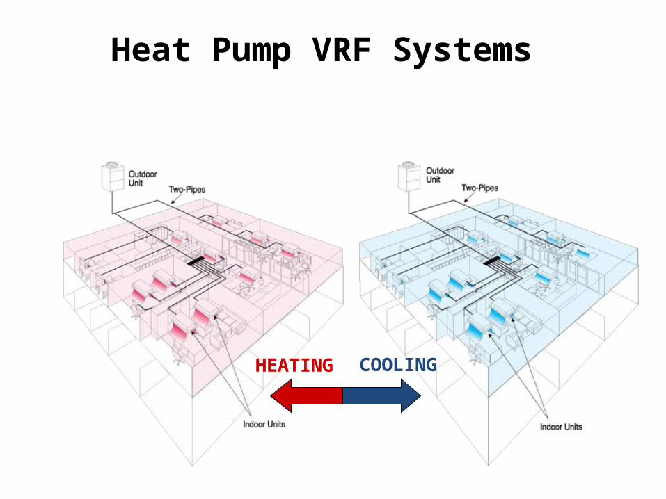
Heat Recovery VRF SystemsOutdoor Unit or Water-source Unit

Basic Refrigeration Cycle
RED = Higher Temp/Pressure
BLUE = Lower Temp/Pressure

Basic Refrigeration Cycle
High-Pressure
Vapor
High-Pressure
Liquid
Low-Pressure
Liquid
Low-Pressure
Vapor
Condenser
Evaporator

Basic Refrigeration Cycle
RED = Higher Temp/Pressure
BLUE = Lower Temp/Pressure
Expa
nsio
n Cy
cle
Condensing
Evaporating
Com
pres
sion
Cycle
Liquid and Gas
Liquid Gas
Subcooled Liquid
Superheated Gas
Pres
sure
Enthalpy

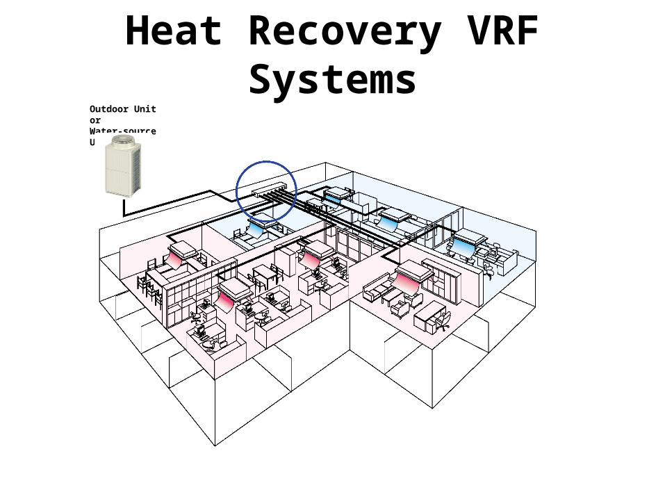
Accumulator• Provide compressor protection from
liquid slugging during startup• Stores refrigerant not required in
low load conditions• Assures adequate vapor and oil
return
Accumulator
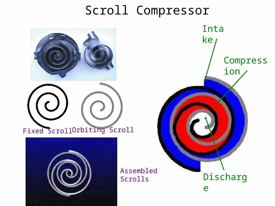
Scroll CompressorIntake
Compression
Discharge
Fixed Scroll Orbiting Scroll
AssembledScrolls
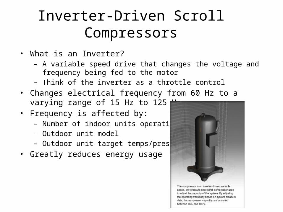
Inverter-Driven Scroll Compressors
• What is an Inverter?– A variable speed drive that changes the voltage and frequency being fed to
the motor– Think of the inverter as a throttle control
• Changes electrical frequency from 60 Hz to a varying range of 15 Hz to 125 Hz
• Frequency is affected by:– Number of indoor units operating– Outdoor unit model– Outdoor unit target temps/pressures
• Greatly reduces energy usage

Compressor
High-Pressure
Vapor
High-Pressure
Liquid
Low-Pressure
Liquid
Low-Pressure
Vapor
Condenser
Evaporator
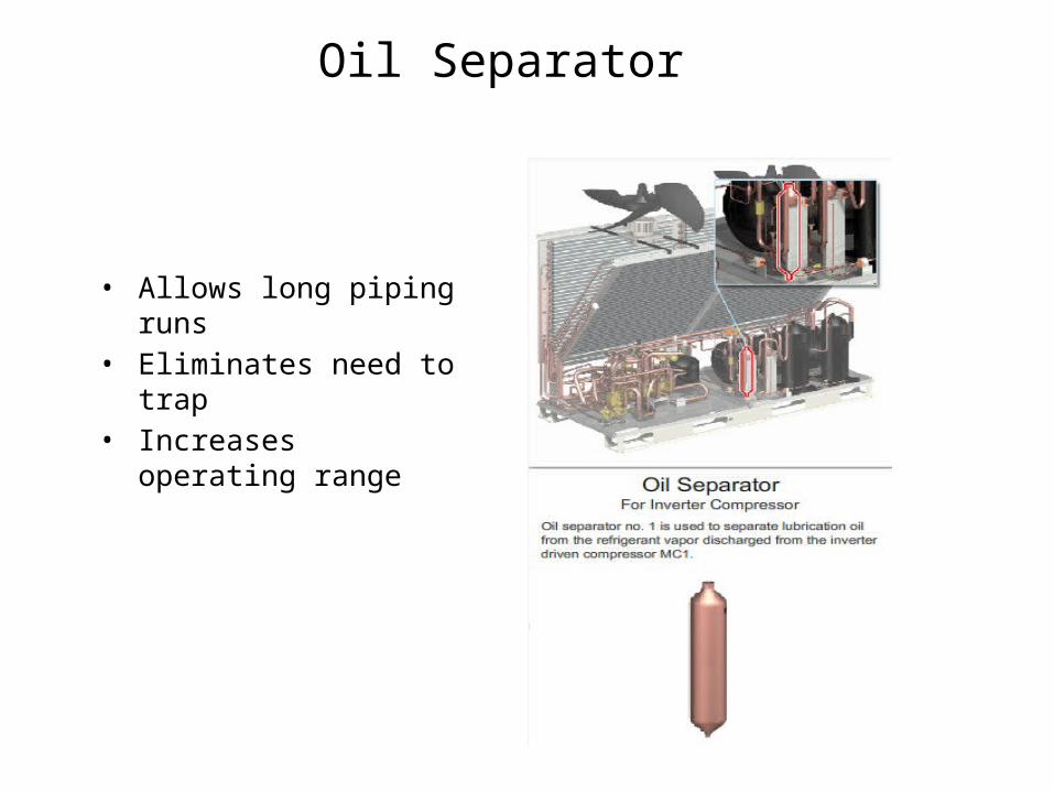
Oil Separator
• Allows long piping runs• Eliminates need to trap• Increases operating range

Oil Separator
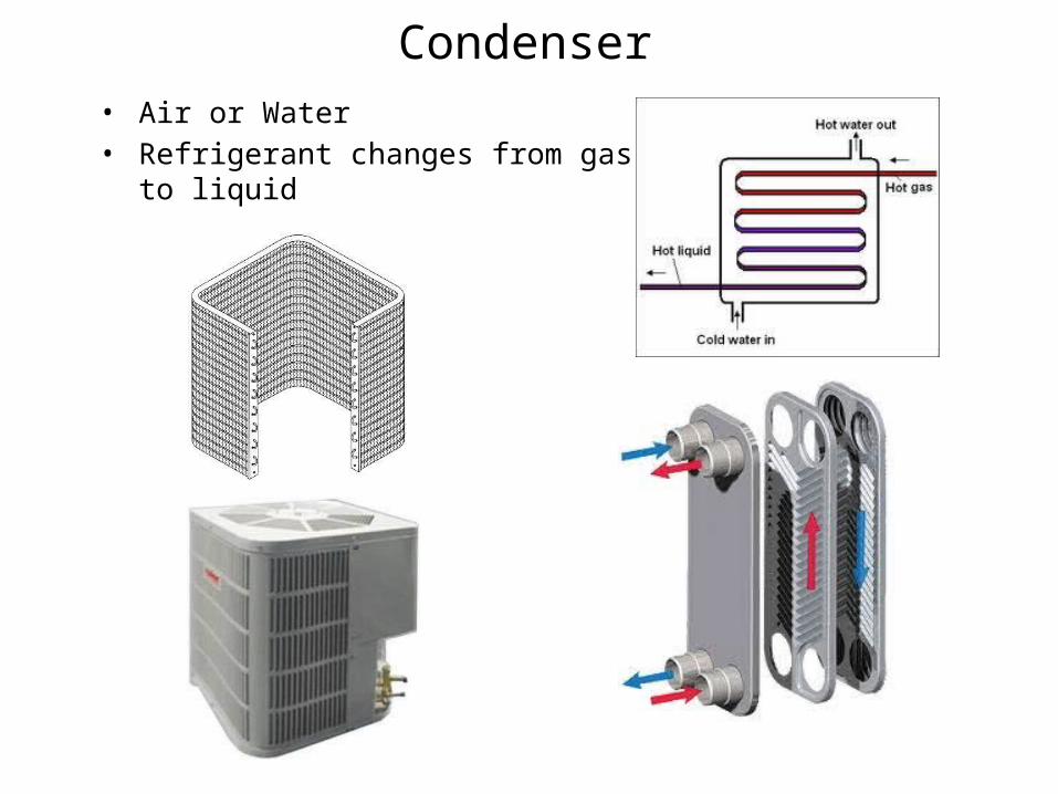
Condenser• Air or Water• Refrigerant changes from gas to liquid

Segmented Heat Exchangers
• Segments use valves• Capacity control• Improves efficiency• Simultaneous heat/cool/heat
recovery
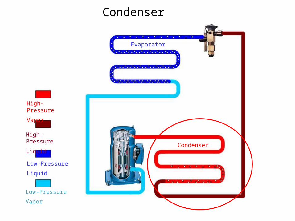
Condenser
High-Pressure
Vapor
High-Pressure
Liquid
Low-Pressure
Liquid
Low-Pressure
Vapor
Condenser
Evaporator
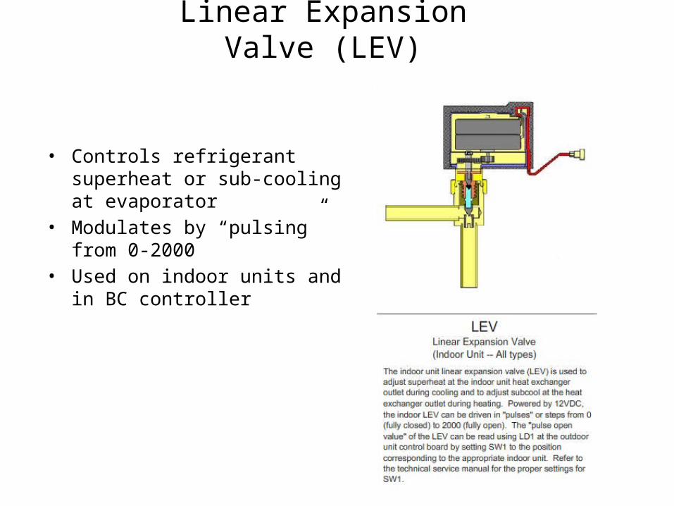
Linear Expansion Valve (LEV)
• Controls refrigerant superheat or sub-cooling at evaporator
• Modulates by “pulsing” from 0-2000• Used on indoor units and in BC
controller
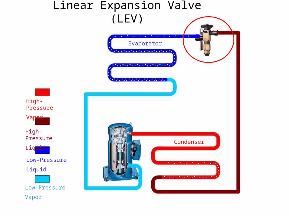
Linear Expansion Valve (LEV)
High-Pressure
Vapor
High-Pressure
Liquid
Low-Pressure
Liquid
Low-Pressure
Vapor
Condenser
Evaporator
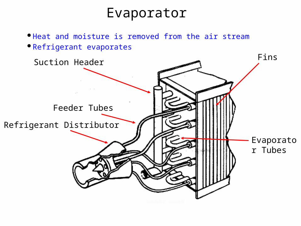
Evaporator
Refrigerant Distributor
Suction Header
Feeder Tubes
Fins
Evaporator Tubes
Heat and moisture is removed from the air streamRefrigerant evaporates
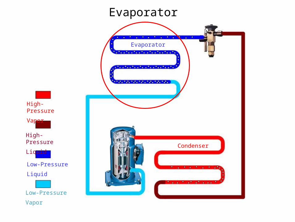
Evaporator
High-Pressure
Vapor
High-Pressure
Liquid
Low-Pressure
Liquid
Low-Pressure
Vapor
Condenser
Evaporator
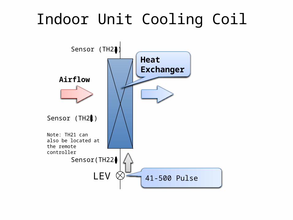
HeatExchanger
LEV
Sensor(TH22)
Sensor (TH23)
41-500 Pulse
Sensor (TH21)
Note: TH21 can also be located at the remote controller
Airflow
Indoor Unit Cooling Coil
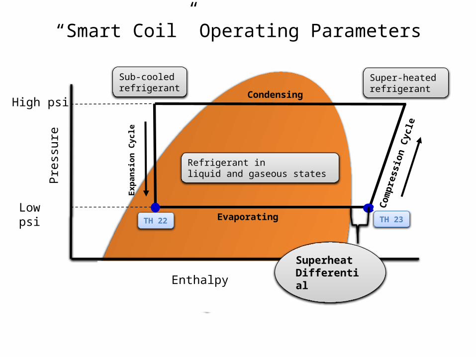
Expa
nsio
n Cy
cle
Low psi
High psiCondensing
EvaporatingTH 22
Com
pres
sion
Cyc
le
Refrigerant in liquid and gaseous states
Sub-cooled refrigerant
Super-heated refrigerant
Superheat Differential
TH 23
Pres
sure
“Smart Coil” Operating Parameters
Enthalpy
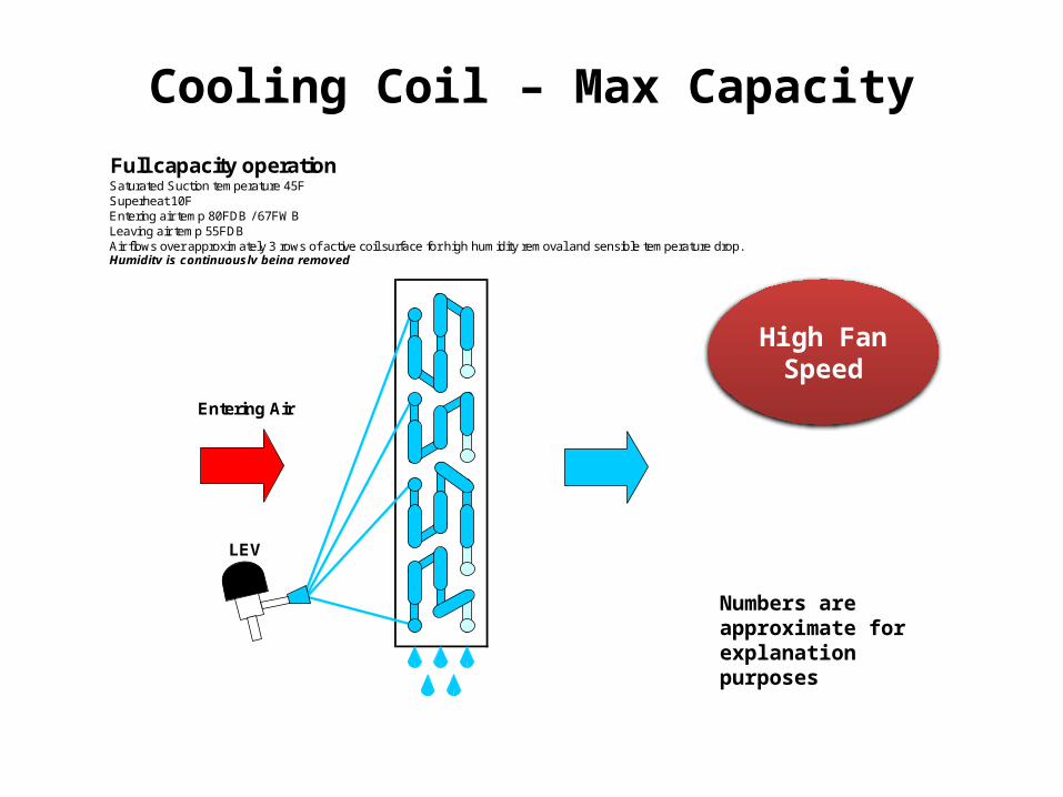
Cooling Coil – Max Capacity
Numbers are approximate for explanation purposes
High Fan Speed
Full capacity operationSaturated Suction temperature 45FSuperheat 10FEntering air temp 80FDB / 67FWBLeaving air temp 55FDBAir flows over approximately 3 rows of active coil surface for high humidity removal and sensible temperature drop.Humidity is continuously being removed
LEV
Entering Air
High Fan Speed

Cooling Coil – Reduced Capacity
Numbers are approximate for explanation purposes
Reduced Capacity (66% of maximum)Saturated Suction temperature 45FSuperheat 15FEntering air temp 77FDB / 64FWBLeaving air temp 60FDBAir flows over approximately 2 rows of active coil surface. This reduces humidity removal but all air still flows over active coil surface continously.Humidity is continuously being removed
LEV
Entering Air
High Fan Speed

Cooling Coil – Low Capacity
Numbers are approximate for explanation purposes
Reduced Capacity (33% of maximum)Saturated Suction temperature 45FSuperheat 20FEntering air temp 75FDB / 63FWBLeaving air temp 65FDBAir flows over approximately 1 row of active coil surface. This reduces humidity removal but all air still flows over active coil surface continously.Humidity is continuously being removed
LEV
Entering Air
High Fan Speed

Dry Mode Saturated Suction temperature 45FSuperheat 10F or lessEntering air temp 80FDB / 67FWBLeaving air temp 50FDBAir flows over approximately 3 rows of active coil surface for high humidity removal and sensible temperature drop.High amounts of Humidity are being removed
Entering Air
LEV
Cooling Coil – Dry Mode
Numbers are approximate for explanation purposes
Low or Extra-Low Fan Speed
Low or Extra-Low Fan Speed

Cooling Coil – Dry Mode
Indoor LEV
THERMOSTAT ROOM TEMP ON OFF
CALLING 82° or more 9 Minutes 3 Minutes
CALLING 79° - 82° 7 Minutes 3 Minutes
CALLING 75° - 79° 5 Minutes 3 Minutes
CALLING 64° - 75° 3 Minutes 3 Minutes
CALLING less than 64° -- Always
SATISFIED 64° or more 3 Minutes 10 Minutes
SATISFIED less than 64° -- Always
Fan runs continuously
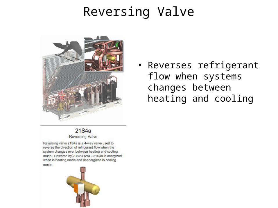
Reversing Valve
• Reverses refrigerant flow when systems changes between heating and cooling
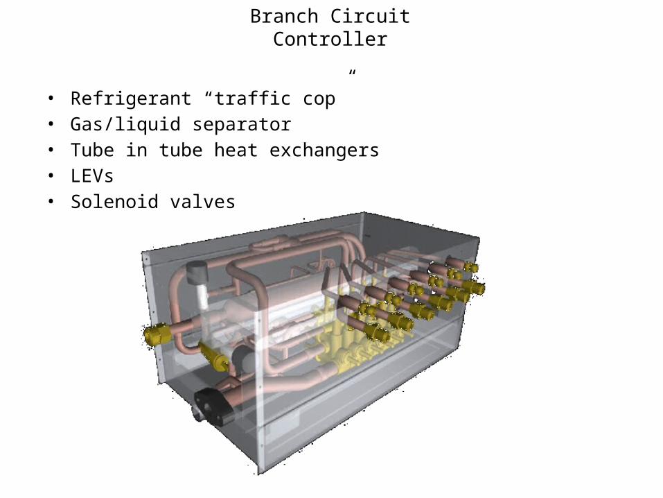
Branch Circuit Controller
• Refrigerant “traffic cop”• Gas/liquid separator• Tube in tube heat exchangers• LEVs• Solenoid valves
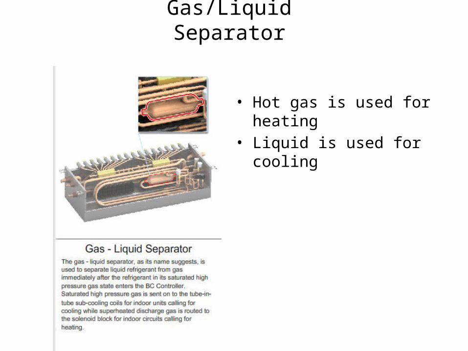
Gas/Liquid Separator
• Hot gas is used for heating• Liquid is used for cooling

Tube-in-Tube Heat Exchangers
• Provides sub-cooling in heating mode
• Provides super-heating in cooling mode

Solenoid Valves
• Block of valves used to control refrigerant direction

Full Port Valves
• Recommended at BC controller• Helps with evacuation during install• Isolates branches for maintenance• Allows additional branches for future use

VRF Piping Considerations• Keep pipe as straight as possible to avoid pressure drops• Long bends instead of elbows when possible (90° ~ 1ft length)• No refrigerant specialties/accessories/traps (minimize restrictions)
– Oil separator and accumulator in outdoor unit• Selection program sizes piping for you• Pipe length = pressure changes = capacity/performance
– Vertical difference between units:• CU below Indoor units - 131 ft (CU to Indoor)• CU above Indoor units - 164 ft (CU to Indoor)• 131/196 ft length from BC controller to furthest indoor unit• 49 ft height difference between indoor units and/or BC controller
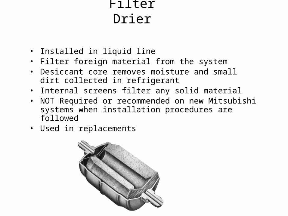
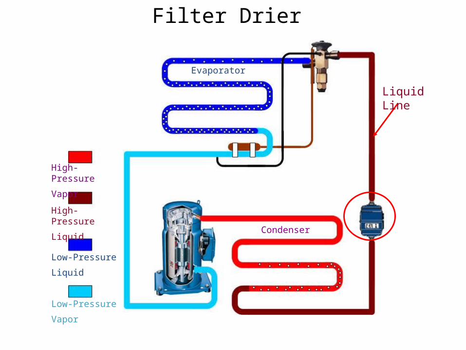
Filter Drier
• Installed in liquid line• Filter foreign material from the system• Desiccant core removes moisture and small dirt collected in
refrigerant• Internal screens filter any solid material• NOT Required or recommended on new Mitsubishi systems when
installation procedures are followed• Used in replacements
High-Pressure
Vapor
High-Pressure
Liquid
Low-Pressure
Liquid
Low-Pressure
Vapor
Condenser
Evaporator
Filter Drier
Liquid Line

Sight Glass
• In Liquid line • Visual indication whether system is contaminated with moisture
– Green is dry, Yellow is wet• Shows bubbles which could indicate problem & assists in charging system• NOT used in VRF equipment
– Refrigerant state is constantly changing
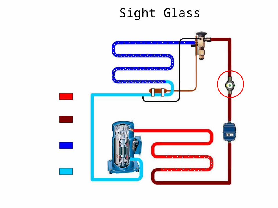
Sight Glass

Piping Considerations• Suction line velocity ~ 1200 ft/min
– Sized for minimum capacity– Oil return is #1 concern– Pitch piping towards compressor– Trap with condenser above evaporator
• Help with oil return especially during off cycle– Inverted trap with evaporator above condenser
• Helps to prevent slugging liquid• Not required with pump down

Oil Traps
• Assist in oil return to compressor• Prevent oil accumulation in
evaporator• Installed in suction line when
compressor is above evaporator• Not required or recommended in
VRF systems
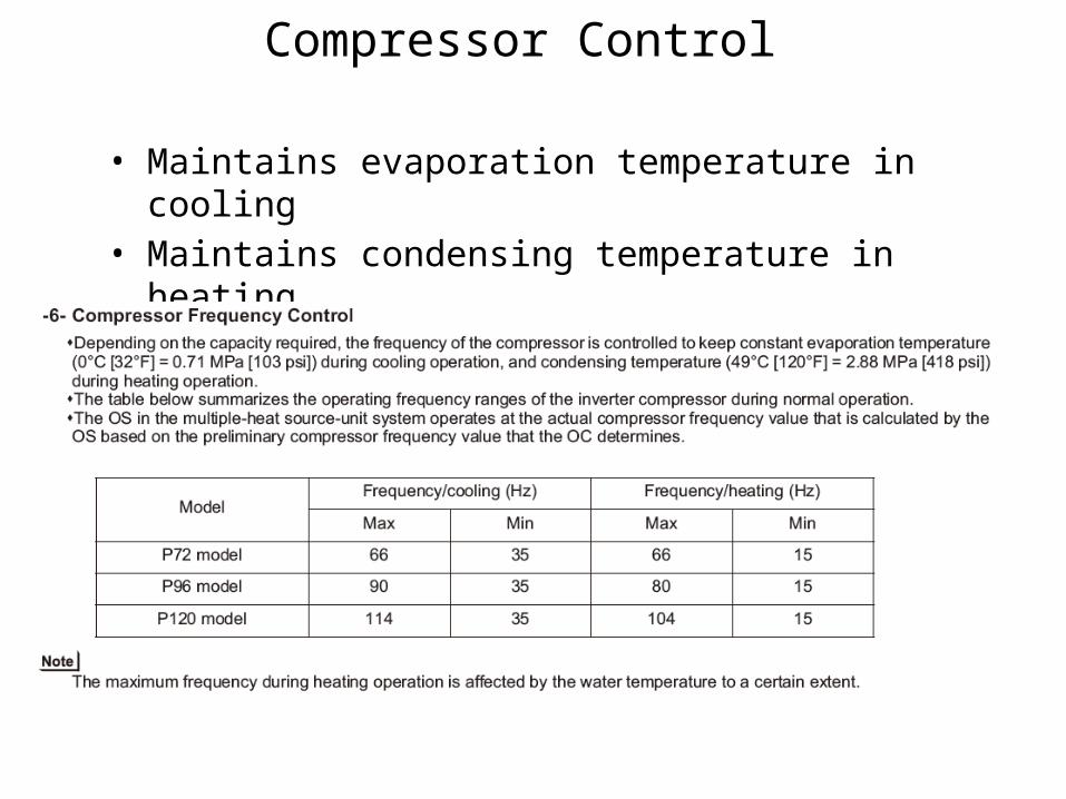
Compressor Control
• Maintains evaporation temperature in cooling• Maintains condensing temperature in heating
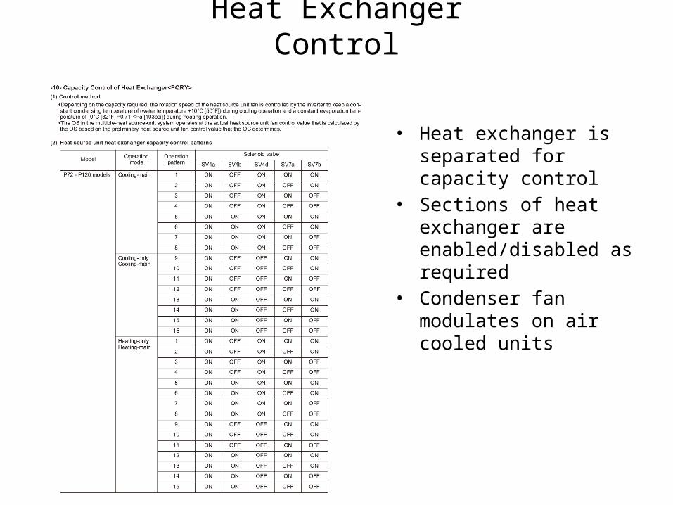
Heat Exchanger Control
• Heat exchanger is separated for capacity control
• Sections of heat exchanger are enabled/disabled as required
• Condenser fan modulates on air cooled units
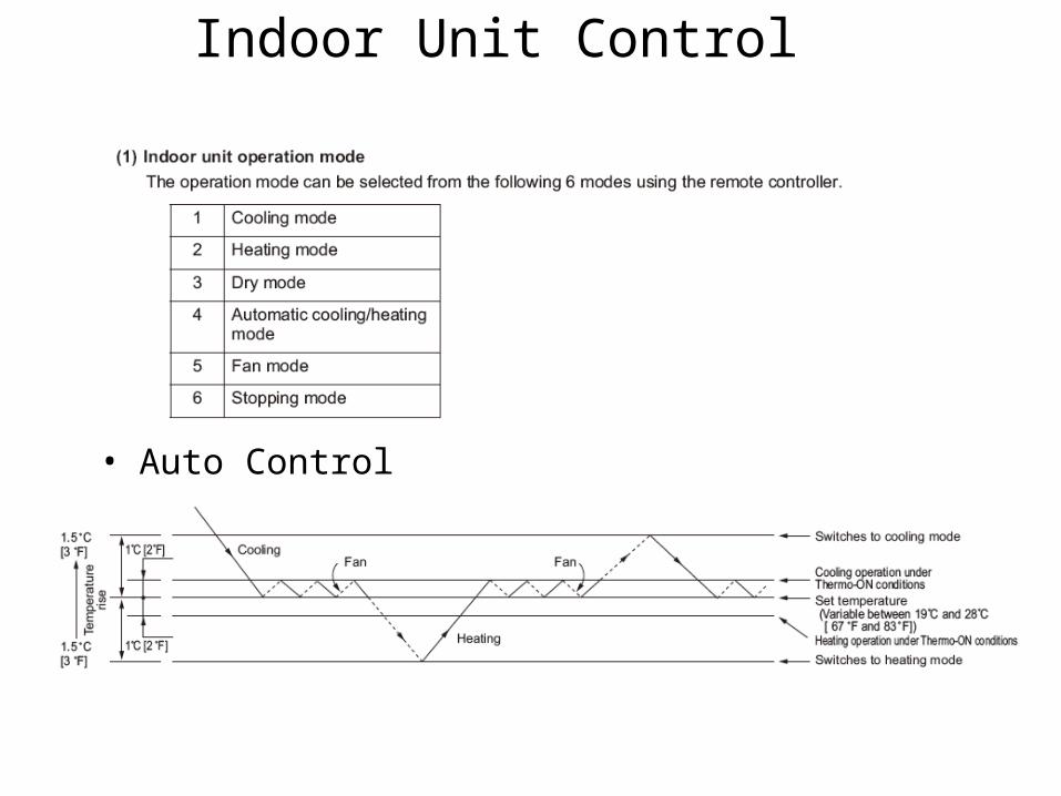
Indoor Unit Control
• Auto Control

Indoor Unit Control
• Modulates LEV and fan speed based on setpoint– Open valve = more flow/capacity– Close valve = less flow/capacity

Thank you for your time