
Pressure and Flow Validation of a Second Generation Gas ...
9
Journal of the Arkansas Academy of Science Volume 56 Article 19 2002 Pressure and Flow Validation of a Second Generation Gas Extraction Probe for a Hybrid Rocket Gas Extraction System Constance Meadors University of Arkansas at Lile Rock Andrew B. Wright University of Arkansas at Lile Rock Follow this and additional works at: hp://scholarworks.uark.edu/jaas Part of the Aerodynamics and Fluid Mechanics Commons is article is available for use under the Creative Commons license: Aribution-NoDerivatives 4.0 International (CC BY-ND 4.0). Users are able to read, download, copy, print, distribute, search, link to the full texts of these articles, or use them for any other lawful purpose, without asking prior permission from the publisher or the author. is Article is brought to you for free and open access by ScholarWorks@UARK. It has been accepted for inclusion in Journal of the Arkansas Academy of Science by an authorized editor of ScholarWorks@UARK. For more information, please contact [email protected], [email protected]. Recommended Citation Meadors, Constance and Wright, Andrew B. (2002) "Pressure and Flow Validation of a Second Generation Gas Extraction Probe for a Hybrid Rocket Gas Extraction System," Journal of the Arkansas Academy of Science: Vol. 56 , Article 19. Available at: hp://scholarworks.uark.edu/jaas/vol56/iss1/19
Transcript of Pressure and Flow Validation of a Second Generation Gas ...

Journal of the Arkansas Academy of Science
Volume 56 Article 19
2002
Pressure and Flow Validation of a SecondGeneration Gas Extraction Probe for a HybridRocket Gas Extraction SystemConstance MeadorsUniversity of Arkansas at Little Rock
Andrew B. WrightUniversity of Arkansas at Little Rock
Follow this and additional works at: http://scholarworks.uark.edu/jaas
Part of the Aerodynamics and Fluid Mechanics Commons
This article is available for use under the Creative Commons license: Attribution-NoDerivatives 4.0 International (CC BY-ND 4.0). Users are able toread, download, copy, print, distribute, search, link to the full texts of these articles, or use them for any other lawful purpose, without asking priorpermission from the publisher or the author.This Article is brought to you for free and open access by ScholarWorks@UARK. It has been accepted for inclusion in Journal of the Arkansas Academyof Science by an authorized editor of ScholarWorks@UARK. For more information, please contact [email protected], [email protected].
Recommended CitationMeadors, Constance and Wright, Andrew B. (2002) "Pressure and Flow Validation of a Second Generation Gas Extraction Probe for aHybrid Rocket Gas Extraction System," Journal of the Arkansas Academy of Science: Vol. 56 , Article 19.Available at: http://scholarworks.uark.edu/jaas/vol56/iss1/19
117
Pressure and Flow Validation of a Second Generation Gas ExtractionProbe for a Hybrid Rocket Gas Extraction System
Constance Meadors and Andrew WrightDepartment of Applied Science
University of Arkansas at Little RockLittle Rock, AR72204
Abstract
Agas extraction system (GES) has been designed for use with the hybrid rocket facility at the University of Arkansas at
Little Rock (UALR) for spectroscopic analysis ofrocket plumes. While monitoring gas flow-rate and pressure, the GES extracts
gases from the hybrid rocket plume and transports them to a mass spectrometer. This paper describes design and constructionofa gas extraction probe (GEP) prototype capable of extracting gases directly from the plume. Gas dynamics equations wereused to design two venturi-type GEP, converging and converging-diverging. The probe was tested with air to verify designassumptions. Flow rate through the U-arm and pressures for each probe were measured and compared.
Introduction
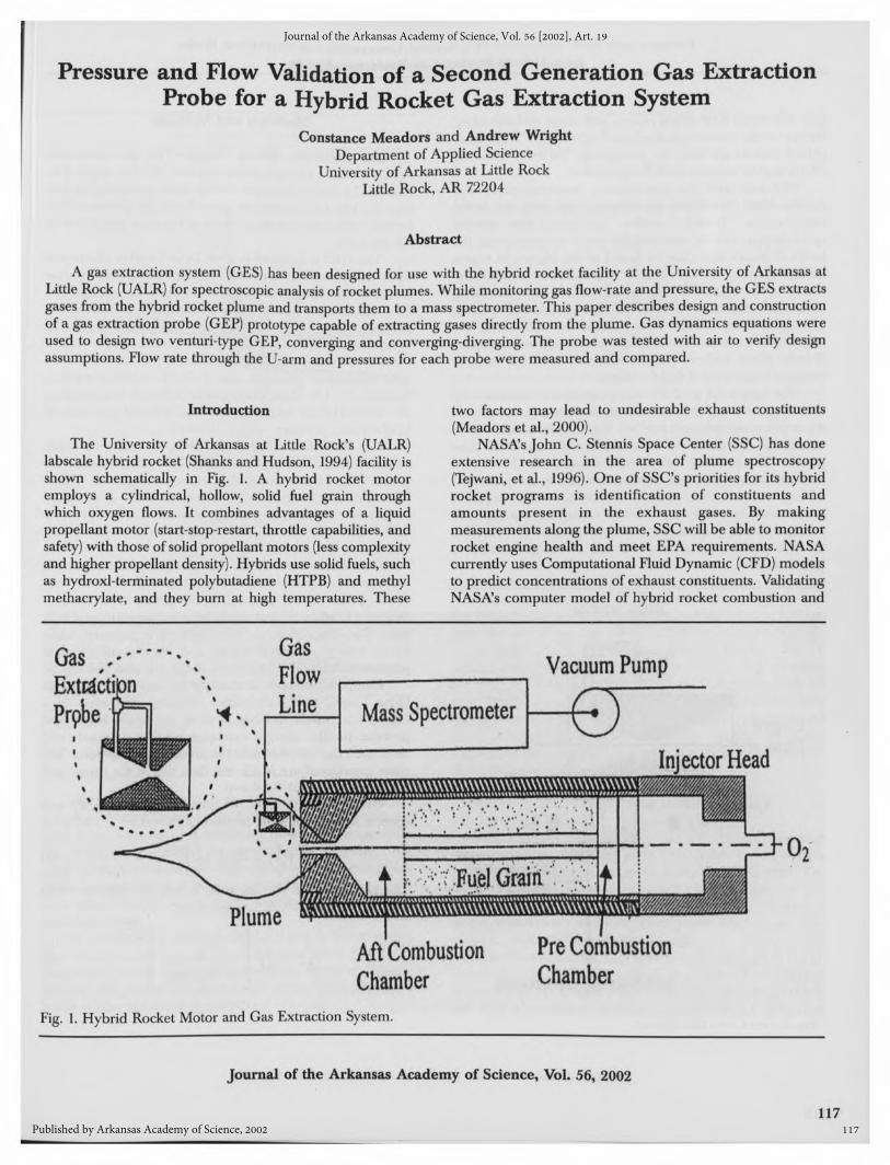
The University of Arkansas at Little Rock's (UALR)abscale hybrid rocket (Shanks and Hudson, 1994) facility ishown schematically in Fig. 1. A hybrid rocket motor
employs a cylindrical, hollow, solid fuel grain throughwhich oxygen flows. It combines advantages of a liquid)ropellant motor (start-stop-restart, throttle capabilities, andafety) with those of solid propellant motors (less complexity
and higher propellant density). Hybrids use solid fuels, suchas hydroxl-terminated polybutadiene (HTPB) and methylmethacrylate, and they burn at high temperatures. These
two factors may lead to undesirable exhaust constituents(Meadors et al, 2000).
NASA's John C. Stennis Space Center (SSC) has doneextensive research in the area of plume spectroscopy(Tejwani, et al., 1996). One of SSC's priorities for its hybridrocket programs is identification of constituents andamounts present in the exhaust gases. By makingmeasurements along the plume, SSC willbe able to monitorrocket engine health and meet EPA requirements. NASAcurrently uses Computational FluidDynamic (CFD) modelsto predict concentrations of exhaust constituents. ValidatingNASA's computer model of hybrid rocket combustion and
Fig. 1. Hybrid Rocket Motor and Gas Extraction System
Journal of the Arkansas Academy of Science, Vol. 56, 2002
117
Journal of the Arkansas Academy of Science, Vol. 56 [2002], Art. 19
Published by Arkansas Academy of Science, 2002
118
for a Hybrid Rocket Gas Extraction System
flow willsatisfy EPA requirements with more realistic safetyfactors on the rocket's performance envelope. Iflarge-scalehybrid rockets are used for propulsion, the environmentaleffects due to exhaust must be quantified.
Materials and Methods
Gas Extraction System Design.--The gas extractionsystem consists of a gas collection unit (GCU), a gas flowline (GFL), and a Finnegan 5100B mass spectrometer (seeFig. 1). The GCU removes gases from the plume of thehybrid rocket and transports them to the mass spectrometervia the GFL.
SSC also uses the non-invasive instrumentation andmeasurement techniques to monitor and diagnose failedcomponents. NASA studies indicate that plumespectroscopy can be successfully used in monitoring thelevels of metals that may be found in the plumes of rocketmotors (Tejwani et al., 1996). Itis possible to monitor thehealth of the engine during operation and, by quantifyingmetals detected in the plume, determine excessive wearingof engine components. This method of monitoring theengine aids in inspection and flightcertification of the SpaceShuttle Main Engine (SSME). It may also be used to
monitor future hybrid flight systems.
The GES is designed to meet hybrid rocket plume andmass spectrometer interface requirements. Fcr plumeinsertion, the design specifications of the GES are minimalflow disturbance and continuous sampling. Temperature,pressure, and Mach number are determined from thehybrid rocket plume. The hybrid rocket plume has a3000°C temperature (Teague, et al., 1996), 30 psi (206.8kPa) stagnation pressure, and a Mach number varyingbetween 0.5-1.5. Mass spectrometer interface requirementsare 20-25mL/min inlet flow rate and 0.19-.09 psi ( 1.3.66kPa) vacuum pressure.
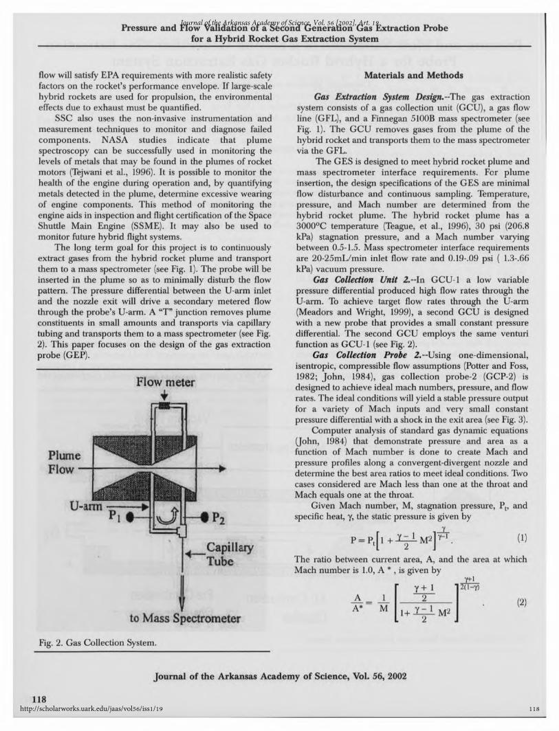
The long term goal for this project is to continuouslyextract gases from the hybrid rocket plume and transportthem to a mass spectrometer (see Fig. 1). The probe willbeinserted in the plume so as to minimally disturb the flowpattern. The pressure differential between the U-arm inletand the nozzle exit will drive a secondary metered flowthrough the probe's U-arm. A "T"junction removes plumeconstituents in small amounts and transports via capillarytubing and transports them to a mass spectrometer (see Fig.2). This paper focuses on the design of the gas extractionprobe (GEP).
Gas Collection Unit 2.-In GCU-1 a low variablepressure differential produced high flow rates through theU-arm. To achieve target flow rates through the U-arm(Meadors and Wright, 1999), a second GCU is designedwith a new probe that provides a small constant pressuredifferential. The second GCU employs the same venturifunction as GCU-1 (see Fig. 2).
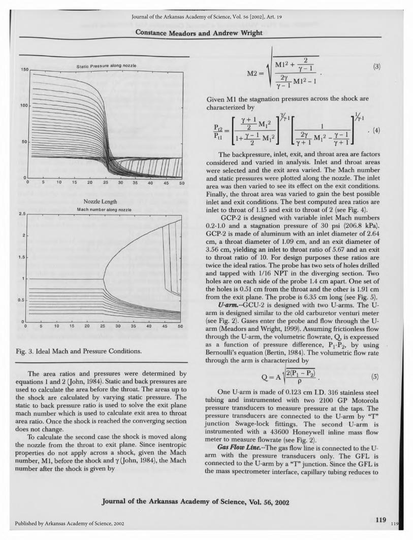
Gas Collection Probe 2.--Using one-dimensional,isentropic, compressible flow assumptions (Potter and Foss,1982; John, 1984), gas collection probe-2 (GCP-2) isdesigned to achieve ideal mach numbers, pressure, and flowrates. The ideal conditions willyield a stable pressure outputfor a variety of Mach inputs and very small constantpressure differential witha shock in the exitarea (see Fig. 3).
Flow meter
Computer analysis of standard gas dynamic equations(John, 1984) that demonstrate pressure and area as afunction of Mach number is done to create Mach andpressure profiles along a convergent-divergent nozzle anddetermine the best area ratios to meet ideal conditions. Twocases considered are Mach less than one at the throat andMach equals one at the throat.
Given Mach number, M,stagnation pressure, P t, andspecific heat, y, the static pressure is given by
P-P.fl+lfi-M^. (1). Capillary
Tube The ratio between current area, A, and the area at whichMach number is 1.0, A
*,is given byY±l
Y+l ]2(l-y)A 1 2 (2)A* M 1+ Y^LM2
to Mass Spectrometer 2
Fig. 2. Gas Collection System.
Journal of the Arkansas Academy of Science, Vol. 56, 2002
118
Journal of the Arkansas Academy of Science, Vol. 56 [2002], Art. 19
http://scholarworks.uark.edu/jaas/vol56/iss1/19
Constance Meadors and Andrew Wright
119
IThe area ratios and pressures were determined by
lations 1and 2 (John, 1984). Static and back pressures ared to calculate the area before the throat. The areas up to
shock are calculated by varying static pressure. Theic to back pressure ratio is used to solve the exit planech number which is used to calculate exit area to throata ratio. Once the shock is reached the converging section;s not change.To calculate the second case the shock is moved along
the nozzle from the throat to exit plane. Since isentropicproperties do not apply across a shock, given the Machnumber, Ml,before the shock and y(John, 1984), the Machnumber after the shock is given by
\ Ml2+7TT
M2 = I—z !'
y- 1
(3)
Given Mlthe stagnation pressures across the shock arecharacterized by
Pti i-Oz± Ml2 -^L-M^-Xzi2 !J Ly+1 l y+ 1.•(4)
The backpressure, inlet,exit,and throat area are factorsconsidered and varied in analysis. Inlet and throat areaswere selected and the exit area varied. The Mach numberand static pressures were plotted along the nozzle. The inletarea was then varied to see its effect on the exit conditions.Finally, the throat area was varied to gain the best possibleinlet and exit conditions. The best computed area ratios areinlet to throat of 1.15 and exit to throat of 2 (see Fig. 4).
GCP-2 is designed with variable inlet Mach numbers0.2-1.0 and a stagnation pressure of 30 psi (206.8 kPa).GCP-2 is made of aluminum with an inlet diameter of 2.64cm, a throat diameter of 1.09 cm, and an exit diameter of3.56 cm, yielding an inlet to throat ratio of 5.67 and an exitto throat ratio of 10. For design purposes these ratios aretwice the ideal ratios. The probe has two sets of holes drilledand tapped with 1/16 NPT in the diverging section. Twoholes are on each side of the probe 1.4 cm apart. One set ofthe holes is 0.51 cm from the throat and the other is 1.91 cmfrom the exit plane. The probe is 6.35 cm long (see Fig. 5).
U-arnu --GCU-2 is designed with two U-arms. The U-arm is designed similar to the old carburetor venturi meter(see Fig. 2). Gases enter the probe and flow through the U-arm (Meadors and Wright, 1999). Assuming frictionless flowthrough the U-arm, the volumetric flowrate, Q, is expressedas a function of pressure difference, P1-P2, by usingBernoulli's equation (Bertin, 1984). The volumetric flow ratethrough the arm is characterized bycharacterized by
(5)
One U-arm is made of 0.123 cm I.D. 316 stainless steeltubing and instrumented with two 2100 GP Motorolapressure transducers to measure pressure at the taps. Thepressure transducers are connected to the U-arm by "T"junction Swage-lock fittings. The second U-arm isinstrumented with a 43600 Honeywell inline mass flowmeter to measure flowrate (see Fig. 2).
Gas Flow Line.~The gas flowline is connected to the U-arm with the pressure transducers only. The GFL isconnected to the U-arm by a "T"junction. Since the GFL isthe mass spectrometer interface, capillary tubing reduces to
Fig. 3. Ideal Mach and Pressure Conditions
Journal of the Arkansas Academy of Science, Vol.56, 2002
119
Journal of the Arkansas Academy of Science, Vol. 56 [2002], Art. 19
Published by Arkansas Academy of Science, 2002

120
for a Hybrid Rocket Gas Extraction System
Static Pressure along nozzle100 i
,1
, ,1
, , , ,1
90 - -80 •
ol 1 1 > 1 ¦ 1 1 1 1
0 5 10 15 20 25 30 35 40 45 50
Nozzle Length
Mach number along nozzle3.6, , , , , , , , , ,
1
0 5 10 15 20 25 30 35 40 45 50
Nozzle Length
Fig. 4. Best Mach and Pressure Conditions
molecular flow.Molecular flow is characterized as
c =&mP |m' (6)
where k is Boltsmann's constant and T is the absolutetemperature. The GFL is made of 0.25 cm I.D. stainlesssteel capillary tubing.
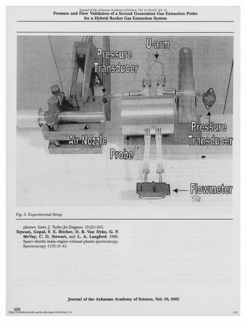
Experimental.~GCU-2 was constructed. A 0.33cmdiameter pressure-regulated nozzle was placed 2.54 cmfrom the inlet of the probe. While inlet air pressure wasvaried, pressure and flow measurements were taken at thetaps (see Fig. 6). The output of the pressure transducers wasconditioned and converted to voltage using LM741 op-amps. The voltages were measured with a hand-heldmultimeter.
Given the pressure measurements, volumetric flowthrough the U-arm was calculated using equation 5 andcompared with measurements (see Table 1). The Machnumbers at the taps, Ml and M2, were calculated bysubstituting static pressures in equations 1 and 2. After P t
and A*were eliminated from these equations, Mland M2were solved simultaneously. The stagnation pressure, P t,wascomputed directly from equation 1.
Results and Discussion
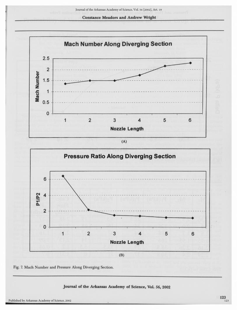
Data collected from GCU-2 is shown in Table 1. TheMach numbers and pressure ratios at the taps were plottedalong the nozzle to compare with ideal and best designconditions (see Fig. 7). Itcan be seen that as the flow in theunit increased, the pressure ratio stabilizes representingchoked flow and a shock in the diverging section. Chokedflow in the nozzle is achieved over a range of inlet Machnumbers (0.2-1.0). However, as the shock moves toward theexit plane, the flow rate and pressure fluctuate signifyingconditions predicted by computer analysis (see Fig. 4).Controlling the location of the shock could further controlthe flow rate.
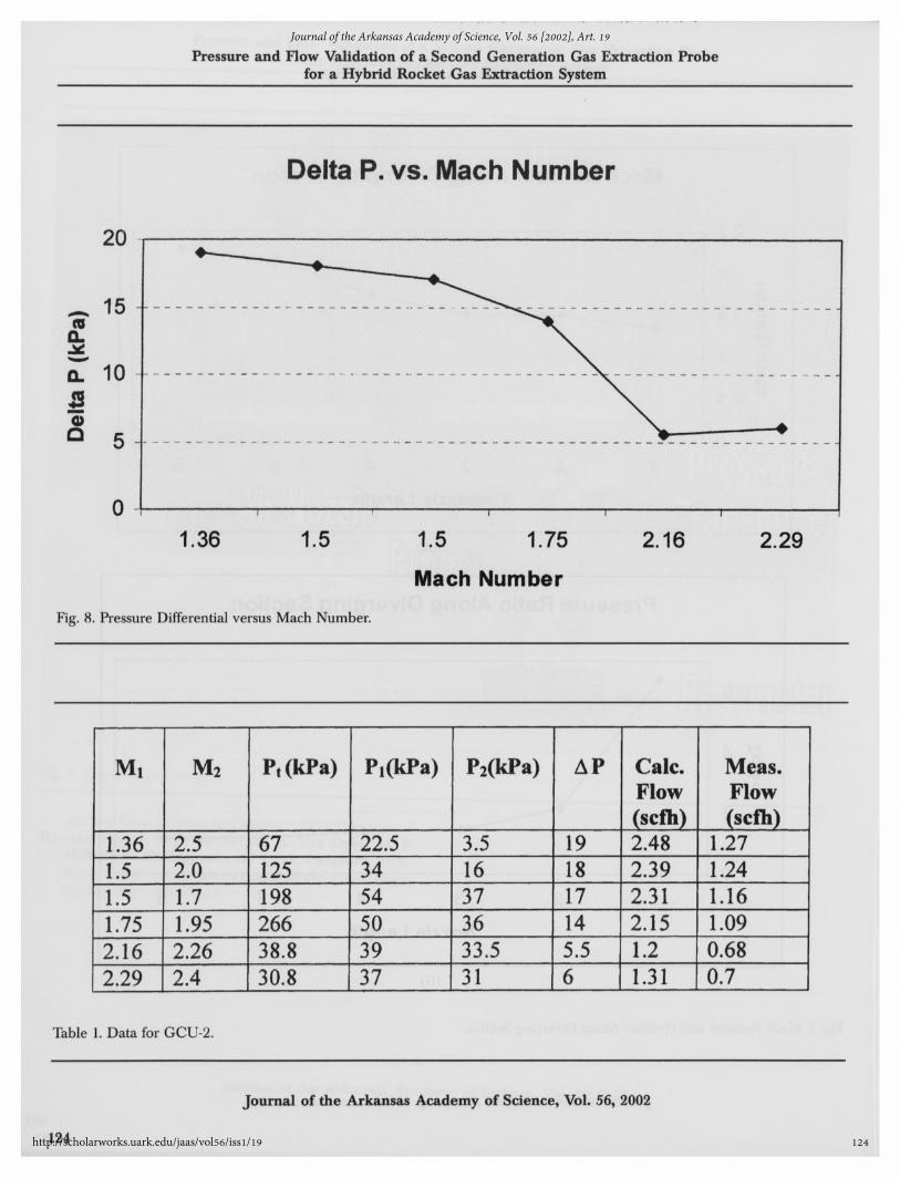
The pressure differential versus the Mach number at tapone was plotted (see Fig. 8). As inlet pressure and Machnumber increased, the pressure differential decreased. Thesmall changes in pressure in the nozzle produce reducedflow through the U-arm and a stable range of flow rates.With constant flow rates in the U-arm, the pressure and flowrate into the mass spectrometer can be controlled.
The volumetric flow through the U-arm was predictedusing equation 3 and measured with an in-line mass flowmeter. The predicted flow was higher than the actual flow.The connection of the flow meter to the taps resulted inlosses of pressure drop across the flow meter. The flowmeasurements provide qualitative confirmation of thedesign.
Conclusions
The prototype, GCU-2, qualitatively verified the designconcept. Pressure and flow measurements were taken tovalidate the design concept and generate preliminary designinformation for the next iteration. GCP-2 verified that witha shock in the U-arm, constant flow and pressure into themass spectrometer or other measuring devices can beachieved over a range of inlet pressures. A high and lowflow probe can be designed to transport gases from therocket to the mass spectrometer. Pressure measurements at
the GFL should be taken to confirm flow rate into the massspectrometer.
Acknowledgments. —We would like to thank William
St. Cyr and personnel at NASA Stennis Space Center for
Journal of the Arkansas Academy of Science, Vol. 56, 2002
120
Journal of the Arkansas Academy of Science, Vol. 56 [2002], Art. 19
http://scholarworks.uark.edu/jaas/vol56/iss1/19

Constance Meadors and Andrew Wright
121
Fig. 5. Gas Collection Probe-2.
collaboration and assistance in the design of the GCU. Wewould like to thank Armand Tomany for fabrication of the)rototype and for assistance in setting up the flow
experiments. This work is supported by the Arkansas SpaceGrant Consortium through Collaborative Research Projectjrant and student fellowship. This work is also supported by
NASA through a GSRP Fellowship.
Literature Cited
rertin, John J. 1984. Engineering fluid mechanics.Prentice-Hall, Inc., New Jersey.
rhn, E. A. 1984. Gas dynamics. Allyn and Bacon, Inc.,Boston.
Meadors, C. and A.B.Wright June 1999. The design andconstruction of a gas extraction probe for a hybridrocket gas extraction system. AIAA:99-2535.
Meadors, Constance. J. E. Elsasser, A.B. Wright, andM.K.Hudson. July 2000. Design of an optical port inthe combustion chamber of a labscale hybrid rocketmotor. AIAA:2000-3888.
Potter, M.and J. Foss. 1982. Fluid mechanics. Great LakesPress, Inc., Michigan.
Shanks, R. B. and M.K.Hudson. June 1994. The designand control of a labscale hybrid rocket facility forspectroscopy studies. AIAA:94-3016.
Teague, M. Warfield, J. R. Welborn, and Tonya Felix.1996. UV-VISAbsorption as a diagnostic for NOrocket
Journal of the Arkansas Academy of Science, Vol. 56, 2002
121
Journal of the Arkansas Academy of Science, Vol. 56 [2002], Art. 19
Published by Arkansas Academy of Science, 2002
122
for a Hybrid Rocket Gas Extraction System
Fig. 6. Experimental Setup
plumes. Inter. J. Turbojet Engines. 13:211-215.Tejwani, Gopal, F. E. Bircher, D.B. Van Dyke, G. P.
McVay, C. D. Stewart, and L. A. Langford. 1996.Space shuttle main engine exhaust plume spectroscopy.Spectroscopy ll(9):31-43.
Journal of the Arkansas Academy of Science, Vol. 56, 2002
122
Journal of the Arkansas Academy of Science, Vol. 56 [2002], Art. 19
http://scholarworks.uark.edu/jaas/vol56/iss1/19
?
123
Constance Meadors and Andrew Wright
Fig. 7. Mach Number and Pressure Along Diverging Section.
Journal of the Arkansas Academy of Science, Vol. 56, 2002
123
Journal of the Arkansas Academy of Science, Vol. 56 [2002], Art. 19
Published by Arkansas Academy of Science, 2002
124
Pressure and Flow Validation of a Second Generation Gas Extraction Probefor a Hybrid Rocket Gas Extraction System
Mach Number
Fig. 8. Pressure Differential versus Mach Number.
Mi M2 Pt(kPa) P^kPa) P2(kPa) AP Calc. Meas.Flow Flow(scfh) (scfh)
1.36 2.5 67 22.5 3.5 19 2.48 1.271.5 2.0 125 34 16 18 2.39 1.241.5 1.7 198 54 37 17 2.31 1.161.75 1.95 266 _50 36 14 2.15 1.092.16 2.26 38.8 39 33.5 5.5 1.2 0.682.29 1 2.4 1 30.8 | 37 | 31 [6 | 1.31 | 0.7
Table 1. Data for GCU-2
Journal of the Arkansas Academy of Science, Vol. 56, 2002
124
Journal of the Arkansas Academy of Science, Vol. 56 [2002], Art. 19
http://scholarworks.uark.edu/jaas/vol56/iss1/19


